5P01781-A 5P01781-B INSTALLATION AND OPERATING INSTRUCTIONS
|
|
|
- Scott Jennings
- 5 years ago
- Views:
Transcription


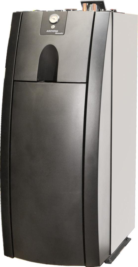
1 5P01781-A 5P01781-B INSTALLATION AND OPERATING INSTRUCTIONS Ariterm Biomatic+ 20i/40i Ariterm Biomatic+ 20i/40i Light Ariterm Biomatic+ 20i/40i Ultra-Light Version
2 TABLE OF CONTENTS GENERAL INFORMATION General information...2 Transport, storage and unpacking...2 Technical data...3 Functional description...4 Safety and alarms...4 Control panel...5 Burner operating principle...5 Boiler installations...6 Pipe installations...7 Wiring diagram Biomatic+ 20i...8 Wiring diagram Biomatic+ 40i...9 Start-up, start and stop Burner settings and parts...11 Heat circuit settings Ariterm Local/Portal Heat circuit settings and connections Alarms and troubleshooting...22 Guarantee and Decommissioning...23 Most common spare parts...23 Service and maintenance Wood pellets as fuel...28 Feeding system...29 The Clean Air Act 1993 and Smoke Control Areas...30 Notes...30 Installation report...31 GENERAL INFORMATION Ariterm Biomatic+ 20i/40i is a cost-effective, resistant, non-condensing and environmentally friendly, self regulating central heating boiler intended for heating of residential houses and production of domestic hot water using pellets. Standard equipment of the Ariterm Biomatic+ 20i/40i includes true lambda control, automatic heating circuit regulation, automatic convection cleaning system, large internal buffer tank, domestic hot water heat exchanger (not in U-L model) and internal access point allowing internet connection. Backup heating (safety feature) is produced by a 9kW immersion heater (not in models L and U-L). Detailed technical data can be found on page 3. To make use of all features of the boiler and burner, it is important to observe these instructions. Read this manual carefully before starting to use your Ariterm Biomatic+ 20i/40i pellet heating unit. Keep this manual in a safe place for future reference. Ariterm reserves for errors and changes. NOTE! Follow the recommendations contained in this manual when using and servicing the burner and the boiler. TRANSPORT, STORAGE AND PACKAGE OPENING Transport The boiler is delivered in a wooden frame. The base is a platform from which the boiler can be safely lifted. The packaging should be unwrapped as close to the installation site as possible. It is important for thereceiver to verify the general state of the boiler before accepting the delivery. In case of damage, the installer/supplier must be contacted without further delay. Storage The boiler should be stored inside. Package opening After removing the packaging, open the ash box and check the accessory list to make sure that all accessories are contained in the delivery (cleaning brush handles are attached to the packaging). Disposing of the packaging The plastic cover is landfill waste and the boards can be burned. ARITERM AB ARITERM OY Installation and operating instruction Version /32
3 TECHNICAL DATA ARITERM BIOMATIC+ Boiler class Performance Dimensions TECHNICAL DATA Biomatic+ 20i Biomatic+ 40i Class according to EN Energy Class EEI hs Power with pellets Combustion efficiency Noise level Dimensions (width x depth x height) Empty weight Water volume Working pressure: boiler Working pressure: heat exchanger* Working temperature* Class 5 A kw 91 % 62 dba 601 x 944 x 1509 mm 245 kg 140 l bar max 10 bar max 110 C Class 5 A kw 93 % 62 dba 606 x 1350 x 1618 mm 455 kg 173 l bar max 10 bar max 110 C Standard delivery Four-way mixing valve ESBE TM 20 Sweeping gear Dirt trap Brick support Flue duct joint Oxygen sensor regulation Shunt motor unit incl. Wireless Room unit Flow water sensor Outdoor temperature compensation Automatic convection cleaning system Domestic Hot Water heat exchanger (Not Ultra-Light model) Domestic Hot Water charge pump (Not Ultra-Light model) Immersion heater 9kW (Not Light or Ultra-Light model) Local Access Point allowing Internet connection Accessories Flue connection Flue connection with ESP-filter Shunt valve, motor and control for additional heat circuit Temp sensors to buffer tank Circulation / Load pump Design and adjustment values Production of hot tap water* 1-shower ( 12 l/min), 520 l/+40 C ) 2-shower (20 l/min, 240 l / +40 C) 1-shower (12 l/min), continously / +40 C) 2-shower (20 l/min, 400 l / +40 C) Flue gas temperature nominal output Flue gas temperature minimum output Flue gas mass flow nominal output Flue gas mass flow minimum output 109 C 65 C 11,5 g/s 4,0 g/s 132 C 76 C 19,6 g/s 8,6 g/s (119) 14 Connections Additional heating circuit unit Domestic water Expansion Discharge Flue pipe connection Pressure drop - connections DN 25 male Cu Ø 22 mm DN 25 male DN 15 female Ø 102 mm 2 0,86 m 3 /h 11 1,72 m 3 /h DN 25 male Cu Ø 22 mm DN 25 male DN 15 female Ø 140 mm 15 1,72 m 3 /h 58 3,44 m 3 /h (1543) 230 (245) Electrical values Power supply Fuse size Power in operation Power consumption - standby Standard model 400V, 3N~, 50 Hz Light & Ultra-Light model 230V, 1N~, 50 Hz Standard model 9 kw immersion heater, 3x16 A Light & Ultra-Light model <1 kw, 1x6 A Burner, ignition 500 W Burner, normal 40 W 19 W Standard model 400V, 3N~, 50 Hz Light & Ultra-Light model 230V, 1N~, 50 Hz Standard model 9 kw immersion heater, 3x16 A Light & Ultra-Light model <1 kw, 1x6 A Burner, ignition 560 W Burner, normal 60 W 19 W 3 5a b (1350) Dimensions of Ariterm Biomatic+ 20i and Biomatic 40i. Dimensions in parentheses specific dimension of Ariterm Biomatic+ 40i. 1. Drain valve DN 15, internal thread 2. Flue 3. Connection for extra heating circuit DN 25, external thread 4. Connection for expansion DN 25, external thread 5a. Outlet to heating circuit from 4-way mixing valve 5b. Return from heating circuit to 4-way mixing valve 6. Domestic cold water 7. Domestic hot water 8. Electrical connections 9. Cleaning hatch 10. Ash box 11. Return DN 25, internal thread 12. Thermometer, On/Off button 13. Automatic convection cleaning 14. Flue gas fan 15. Temperature sensors * Not applicable for Ultra-Light model ARITERM AB ARITERM OY Installation and operating instruction Version /32


4 FUNCTIONAL DESCRIPTION SAFETY AND ALARMS Heating with the Ariterm Biomatic+ 20i/40i pellet heating unit is similar to oil heating in many ways. The main difference is that heating with solid fuel produces a certain amount of ash, which must be removed at certain intervals. If the ash is not removed, combustion efficiency will decrease and the burner may malfunction. The integrated pellet burner of the Biomatic+ 20i/40i is equipped with automatic ignition, but can if necessary be manually ignited. The electric ignition system of the burner will only be activated during cold starts, i.e., when the system has been inactive for a long period and the boiler temperature has dropped to at least 7 C below the target temperature. During operation, if not de-activated, the necessary ignition take place by means of the embers in the burner head, i.e. a warm start. This saves electric energy. The burner and the internal feeding system operate automatically. The operation of the burner is controlled by the temperature sensor installed in the boiler. The burner head is due to the true lambda control fed with an accurately defined mixture of fuel and air for optimal combustion, which is both cost-effective and environmentally friendly. The burner auger is over-pressurised during operation. The purpose of this is to reduce the risk of damage to the burner if the draught is weak. The automatic heat regulation system adjusts the supply water temperature according to the outdoor and indoor temperature. For safety reasons, the Biomatic+ 20i/40i and fuel store must be placed apart from each other to prevent possible damage. Any malfunctions or damages caused by incorrect handling will then be limited to the burner. The fuel store must be built as a separate, fire-classified, confined space. Faults that cause the system to stop are indicated by a red indicator light. In addition to this, a text message appears in the web app and an will be sent if the boiler is connected to internet AND addresses are added in menu Alarm: Manage s. During every operating cycle of the external feeding system, a small amount of pellets is fed from the pellet store to the upper connection of the burner. To allow dispense of an accurate and equal amount of pellets during every operation cycle of the burner, the feeding is carried out by means of a separate internal feed system - including feeder screw, locker feeder and burner screw - to the burner head. As the internal burner screw feeds pellets forward three times faster than they arrive at the screw, a safety zone, containing only single pellets, is created between the burner head and the upper connection. This safety zone always remains intact even in the event of power failure, insufficient maintenance or equipment breakage. Alarms are described in Alarms and troubleshooting. Wood pellets according to EN standards with a diameter of 6 or 8 millimeters are the recommended fuel for the boiler. The convection parts of the boiler is automatically cleaned on set intervals. Ash is to be removed from the ash box located in the lower part of the boiler. The external feeding auger must be installed in such a way that its position, with respect to the drop funnel, allows the drop pipe to swing free outside the burner in case of back fire. Biomatic+ 20i Biomatic+ 20i ARITERM AB ARITERM OY Installation and operating instruction Version /32


5 CONTROL PANEL BURNER OPERATING PRINCIPLE Actual boiler temperature 2. Burner control switch on/off/reset 3. Status LED green/red No light = OFF/Shutdown Green = High or Low power mode Green breathing = Standby Green blink = Ignition mode Green = Operation = Alarm 4. Cut out thermostat 5a. Immersion heater back up/ Cut out thermostat 5b. Immersion heater cut out thermostat reset 6. Tap water pump Fuse 7. Main fuse The picture shows 20 kw burner. Locker feeder Feeder screw Upper connection Ignition element Primary air pipe Ignition pipe Safety zone against fire in the back Combustion fan Burner screw Pellets are fed to the burner head from below (underfeeding principle) 7b a ARITERM AB ARITERM OY Installation and operating instruction Version /32
6 BOILER INSTALLATIONS The boiler should be installed by a company with the proper professional qualifications. The installation must always be carried out in accordance with, at the time being, valid local standards and regulations, as well as the Ariterm Installation and Operation Instructions. NOTE! All electrical connections must be carried out by a professionally-qualified electrician. Space requirement The boiler room must always meet, at the time being, valid local standards and regulations. At least one meter of free space is recommended to be left in front of the boiler for cleaning and maintenance operations. It is also recommended to leave about 40 cm of free space on each side and at least 50 cm above the boiler. NOTE! The boiler must be placed at a distance of no less than 180 mm from the back wall. In addition, it must be possible to remove the flue gas fan whenever maintenance requires it. Flue pipe connection and combustion air intake Silicon sealant with a temperature resistance of 350 C can be used as a sealing compound for joints. The flue pipe must be made of steel or equivalent material. The flue pipe length must be dimensioned according to the building requirements. The low temperature of the flue gas from the Biomatic+ 20i/40i gives rise to a risk of condensation in the chimney. Make sure the chimney is well ventilated with the help of draught diverter/inhibitor The chimney flue should be stainless steel or acid-proof. Ensure that the chimney connection (boiler flue to chimney connection) is air tight since, during certain operating cases, there could be an overpressure after the boiler flue. The boiler room ventilation air intake must not be covered. Flue pipe connection and ventilation air intake Biomatic+ 20i Biomatic+ 40i Recommended flue pipe diameter Ø 100 mm Ø 140 mm Recommended flue pipe length 4 m 4 m Recommended underpressure* in the combustion chamber 3-15 Pa 3-15 Pa Ventilation air intake 100 cm cm 2 Recommended under pressure in the chimney >0 >0 * Measure the vacuum in the measurement hole on the left-hand side of the burner. Remove the black screw NOTE! The vacuum in the chimney is not critical since the boiler is equipped with a flue gas fan. However, the chimney must be dimensioned to be able to evacuate the flue gases without overpressure. Overpressure and/or leakage in the chimney can cause the flue gases to leak into the building. Pipe installations Before installing the boiler, the heating system must be flushed and checked by means of a water-pressure test. After installation, make sure that all joints are tight. Ariterm is not responsible for damages caused by leaking joints. Dirt trap and manometer installation It is recommended that the dirt trap delivered with the boiler is installed in the cold water pipe before the domestic hot water heat exchanger. There is no manometer in the Biomatic+ 20i/40i. Therefore, a manometer must be installed in the heating network. Safety valve installation A safety valve must be fitted to the heating system. The valve must be CE marked with a maximum opening pressure of 1.5 bar and a minimum size of DN 15. The safety valve must be chosen according to the highest pressure class of the combination of devices in the heating system. Devices that can close the connection must not be installed between the valve and the boiler. The release pipe must be dimensioned and installed in such a way that it does not limit the valve release efficiency and does not cause risk/danger during the operation of the valve. Electrical installations The Biomatic+ 20i/40i contain an integrated pellet burner, a 9 kw immersion heater (not in L and U-L models) and an internal DHW circulation pump. The boiler also contain an overheat protection for the burner and the immersion heater. The electrical installations related to the boiler must be carried out by an installer with the relevant qualifications and the boiler must be connected according to the enclosed wiring diagram. A safety/maintenance switch must be installed in the voltage supply system of the boiler. Before commissioning Before starting the boiler, the following must be checked: the heating circuit and the boiler are full of water (pressure at least 0.5 bar). air is removed from the internal DHW circulation pump through the venting screw located in the pump head. the flue damper (if any) is open. the flue gas damper plates located on top of the convection part of the boiler is in place. the circulation pump is running. the heating circuit valves are open. the boiler room ventilation air intake is open. the safety valve is in working order and there are no obstacles between the valve and the boiler. ARITERM AB ARITERM OY Installation and operating instruction Version /32
 4. Circulation pump, additional heating circuit 5. Circulation pump, first heating circuit 6. Floor heating network manifolds 7.")
7 PIPE INSTALLATIONS 1. Ariterm Biomatic+ 20i/40i 2. Connection set of the additional heating circuit (under floor or radiator heating) 3. 4-way valve, first heating circuit (raiator or under floor heating) 4. Circulation pump, additional heating circuit 5. Circulation pump, first heating circuit 6. Floor heating network manifolds 7. Radiator heating network 8. Expansion vessel 9. Service shut-off valve 10. Safety valve 11. Filling valve 12. DHW mixing valve ARITERM AB ARITERM OY Installation and operating instruction Version /32
8 Brown White Grey WIRING DIAGRAM - Biomatic+ 20i Charge pump SW. w. pump Brown Brown L1 L2 L3 N PE Tap water pump External auger Yellow/green Filter Flue gas Sensor Boiler Sensor Convection cleaning Fan 3 Cut out Thermostat Yellow/green Relay C Thermostat Contactor A2 A1 1 P C Immersion heater A Main fuse Burner auger SW. on/off SW. Imm. heater Fan 1 LED R/G Brown J26 J105 J101 J24 J4 J23 Yellow/green Ignition element B Oxygen sensor Burner control Switch J10 J102 J103 J104 J25 J6 J28 J27 J5 Flame sensor Level sensors Circulation pump Grey (white) White Yellow (yellow) (orange) Orange CRB (ESBUS communication) Alarm relay Tank sensor (top) Tank sensor (bottom) Brown Brown Brown Orange White grey blue Grey (2x) Brown (2x) White (2x) Brown Fuse w. pump L N PE Com +12V Com +5V PSU A B Brown Grey White N L BM61011v ARITERM AB ARITERM OY Installation and operating instruction Version /32
9 Brown White Grey WIRING DIAGRAM - Biomatic+ 40i Charge pump SW. w. pump Brown Brown L1 L2 L3 N PE Tap water pump External auger Yellow/green Filter Flue gas Sensor Boiler Sensor Fan 3 Cut out Thermostat Convection cleaning Brown Yellow/green Relay C Thermostat Contactor A2 A1 1 P C Immersion heater A Main fuse Burner auger SW. on/off SW. Imm. heater Fan 1 LED R/G Brown Fan2 J26 J105 J101 Yellow/green J24 J4 J23 Ignition element B Oxygen sensor Burner control Switch J10 J102 J103 J104 J25 J6 J28 J27 J5 Flame sensor Level sensors Circulation pump Grey (white) White Yellow (yellow) (orange) Orange CRB (ESBUS communication) Alarm relay Tank sensor (top) Tank sensor (bottom) Brown Brown Brown Orange White grey blue Grey (2x) Brown (2x) White (2x) Brown Fuse w. pump L N PE Com +12V Com +5V PSU A B Brown Grey White N L BM61021v ARITERM AB ARITERM OY Installation and operating instruction Version /32
10 START-UP, START AND STOP Connecting to Ariterm web interface (For more detailed information of the Ariterm Local/Portal Control see Menu structure ) Ariterm Local Control: When the Biomatic+ 20i/40i arrives it is set as an AP (Access Point). You can connect to the boiler by using your WiFi unit, i.e. Smart phone, Computer, Tablet, ipad etc. - Search for accessible wifi-networks in your WiFi unit, a SSID called [serialnumberssid] will appear. - Choose that one and enter password: ariterm123. Now you are connected to the boiler. - Start the web browser of your WiFi unit and you will automatically enter the Log in page of the boiler. (If not, enter the serialnumber of the boiler followed by.se in the address field of your browser.) - Enter the user name (serialnumber of the boiler) and the password (user) and click Log in. Now you will access Ariterm Local Control of the boiler via the web interface and will be able to control the boiler when close by. Ariterm Portal Control: If you want to connect the boiler to internet, go to the Network menu in the Ariterm Local control. - Search for and choose the SSID of the local network that you want to connect to. - Enter the password of the local network. Burner start-up Turn the burner and the internal DHW circulation pump on from the operating switches at the front of the boiler. Thereafter the boiler can be controlled from the Ariterm Local/Portal Control. (If a flow switch controlling the internal DHW pump is fitted, we recommend to set the operating switch to Off mode.) NOTE! In order to achieve best possible combustion and large DHW capacity, our strongest recommendation is to have the internal DHW circulation pump switched on during during summer/low output seasons. The first start-up differs from normal start-up in that there are no pellets in the burner. Likewise, there are no pellets in the external feeding system. Carry out the following actions in connection with the first start-up or if there are no more pellets in the store: 1. Enter the menu Settings: Pellet storage. Set External feeder, forced operation (min) to desired amount of minutes to fill the feeder up. Click at Update. Repeat until the external feeder has fed a couple of liters of pellets into a bucket. 2. Press the burner control switch. Let the external auger run until the level sensors in the burner indicates pellets. If the external auger operates longer than the maximum external auger time, you have to reset the alarm and start again. 3. When the external auger is filled and the level sensors indicates pellets, the burner will start. NOTE! Now you will leave the AP mode. When the boiler is connected to internet via the local network it will start syncing with our server. - Enter portal.aritermgroup.se (same user/password as above) in the web browser of your WiFi unit and you will access Ariterm Portal Control. Via Ariterm Portal Control you will be able to access and control your boiler wherever you are, given that you have internet connection. NOTE! It is at this point strongly recommended to change password. ARITERM AB ARITERM OY Installation and operating instruction Version /32


11 START-UP, START AND STOP BURNER SETTINGS AND PARTS High and Low Power mode - Glow mode After ignition, the burner start operating in High power mode. When the boiler temperature rises to within 5 C of its set value, the burner start operating in Low power mode and will continue to do so until the set boiler temperature is reached. If boiler temperature decreases the burner will once again start operating in High power mode. When the set boiler temperature is reached, the fan will continue to run for one minute before the burner enters Glow mode. While the burner is in Glow mode, the burner auger brings pellets to the burner head on set interval in order to maintain the embers. Cold start At initial start up the burner performs a Cold start. The LED starts blinking green, the fan and the ignition element starts. When the flame sensor detects a flame in the burner head, the burner jumps directly to next start phase. In the last start phase the fan stops and the burner soon begin to operate in High Power mode. Combustion adjustment Normally you don t need to do any combustion adjustments. The fans 1-3 are set to two different power modes. High and Low. The oxygen sensor regulate the fans and adjust the pellet feeding automatically. In a couple of ours after start up you will have an optimized combustion. If you by any reason want to lower the output, please contact your local Ariterm installer. Immersion heater operation (not in models L and UL) According to default settings the immersion heater heats the boiler to set Immersion heater stop temperature. When the boiler temperature drops more than the set Immersion heater start/stop temperature difference the immersion heater starts again. Alternatively, if immersion heater backup mode is set to ON the immersion heater will operate as back up according to set boiler temperatures in the Settings: Main menu, IF the boiler is in Alarm mode. The burner performs cold starts when the boiler temperature decreases more than 7 C below the set value. After maintenance cleaning of the burner head, make sure that the burner performs a Cold start since there are no embers in the burner head. The success of the cold start can be ensured by sufficiently increasing the set boiler water temperature and by changing it back to the desired value after ignition Burner Warm start The burner performs a Warm start when the boiler water temperature is within 8 C of the set temperature. During a Warm start, the burner uses the embers in the burner head for ignition and, by doing so, saves energy. In normal use, when the burner goes from Glow mode to Power mode, the burner performs a Warm start. The burner starts up automatically after power failures (Warm or Cold start depending on the temperature of boiler water). Stop The burner can be stopped at any stage of the combustion process. Set Burner to Off by pressing the burner control switch. The blower will run for one minute after the burner has been stopped. NOTE! Before cutting the power to the boiler it is important to turn the boiler off in a proper way in order to prevent damages to the control card. Press the burner control switch for more than 10 seconds until the flue gas fan starts to pulse Flame detection system 3. Level switch, receiver 4. Upper connection 5. Level switch, transmitter 6. Fan 7. Burner screw 8. Locker feeder 9. Feeder motor 10. Wheels and chain (not in the figure) 11. Primary air pipe 12. Connector panel The picture shows 20 kw burner. ARITERM AB ARITERM OY Installation and operating instruction Version /32


12 MENU STRUCTURE ARITERM LOCAL/PORTAL CONTROL Login The web interface of Ariterm Biomatic+ 20i/40i is Ariterm Local/Portal Control. You enter the control with Username/Password. Further information at Connecting to Ariterm web interface under Start-up, Start and Stop. Home In the Home menu you can see readings as follows: The present operating mode of the burner, On or Off status of the burner, Sync status, Boiler temperature, Room temperature, Outdoor temperature, Estimated pellet level, Oxygen level, Flow water temperature, Buffer tank top temperature, Buffer tank bottom temperature, Flue gas temperature, Flame sensor level, Number of cold starts, Number of warm starts, Maintenance time 1 & 2 and External feeder total runtime. ARITERM AB ARITERM OY Installation and operating instruction Version /32

13 MENU STRUCTURE ARITERM LOCAL/PORTAL CONTROL Alarm In the Alarm menu you can see current alarms and are able to confirm them. You can also view and search the alarm history. Alarm: Manage s In the Alarm: Manage s menu you can add receivers of alarm s and customize them to each address. ARITERM AB ARITERM OY Installation and operating instruction Version /32

14 MENU STRUCTURE ARITERM LOCAL/PORTAL CONTROL Settings: Main In the Settings: Main menu you are able to set the boiler start and stop temperatures (40-90 C), desired room temperature and set the burner in On/Off mode. Settings: Maintenance In the Settings: Maintenance menu you are able to set two different alarm timers. When the external feeder has run set time you will get an . (If is added in alarm menu) Clear the Maintenance alarm by setting Clear Maintenance alarm 1 or 2 to ON and click Update. After each cleaning of the burner you should set the Reset all adjustment values to ON and click Update. ARITERM AB ARITERM OY Installation and operating instruction Version /32

15 MENU STRUCTURE ARITERM LOCAL/PORTAL CONTROL Settings: Immersion heater In the Settings: Immersion heater menu you can set start and stop temperature of the immersion heater. If Immersion heater back-up mode is set to ON the immersion heater will operate as back up according to the boiler temperatures in the Settings: Main menu, IF the boiler is in Alarm mode. Settings: Pellet Storage In the Settings: Pellet storage menu you can manually force feed the external feed screw as well as manage the Estimated pellet level used for alarms of low pellet level. Enter the External feeder Feeding rate and the boiler calculates and alarms at certain level. ARITERM AB ARITERM OY Installation and operating instruction Version /32

16 MENU STRUCTURE ARITERM LOCAL/PORTAL CONTROL Settings: Tank mode At Settings: Tank mode you can activate Tank mode, set Boiler temperature limit and Tank pump start temperature. Profile In the Profile menu you can edit your profile.to be able to edit your profile you must register an address. NOTE! Remember to change the pre-set password used for first log in. ARITERM AB ARITERM OY Installation and operating instruction Version /32
 to Ariterm Portal")

17 MENU STRUCTURE ARITERM LOCAL/PORTAL CONTROL Network In Network menu you are able to scan and select local networks if to connect the boiler to internet, changing from Ariterm Local Control (using the boiler integrated AP) to Ariterm Portal Control. Users In the User menu you can view all users of the boiler. More information at Connecting to Ariterm web interface under Start-up, Start and Stop. ARITERM AB ARITERM OY Installation and operating instruction Version /32

18 MENU STRUCTURE ARITERM LOCAL/PORTAL CONTROL Users: Create user In the Users: Create user menu you can add new users. You are not able to add users in a higher user level than your own. Schedule In the Schedule menu you can see what profile - Schedule, Work, Home or Vacation - currently in operation. Each profile can be edited by clicking the Wrench icon. You activate any of the profiles simply by clicking them. ARITERM AB ARITERM OY Installation and operating instruction Version /32

: Schedule In the Schedule profile you edit the weekly heating schedule defining what weekdays the boiler is to operate")
19 HEAT CIRCUIT SETTINGS ARITERM LOCAL/PORTAL CONTROL Schedule (option): Work/Home In Work and Home profiles you can set desired room temperatures during the day for days away from home Work, or at home Home. Profiles to be activated, either directly in Schedule menu or thru Schedule profile. Schedule (option): Schedule In the Schedule profile you edit the weekly heating schedule defining what weekdays the boiler is to operate according to Work or Home profile. ARITERM AB ARITERM OY Installation and operating instruction Version /32
. NOTE!")


 NOTE! 230V supply to the pump is to be connected separately.")
20 HEAT CIRCUIT SETTINGS AND CONNECTIONS CRB122 Shunt motor unit with Ariterm Local/Portal Control For the first heating circuit the CRB122 unit operates together with the Ariterm Local/Portal Control. Install the CRB122 unit. Connect the CRB122 unit and the outdoor sensor on the same connectors marked In/Outdoor sensor (A). NOTE! When the CRB122 unit is installed at the first heating circuit, operating together with the boiler control, the indoor display of the CRB unit is only used to show and adjust the existing indoor temperature. Any other adjustments, settings, scheduling etc must be made in the Ariterm Local/Portal Control. CRB122 Shunt motor unit with additional heating circuits For additional heating circuits the CRB122 unit is operated as a separate system/control. Install the CRB122 unit by following the supplied manual. NOTE! If placing the CRB122 Shunt motor unit elsewhere than direct at the boiler, make sure that the turning direction of the shunt motor is correct. PWM pump Connect the PWM regulation cable to the fast connectors, blue on blue and brown on brown. (B) NOTE! 230V supply to the pump is to be connected separately. Alarm relay Relay output normally open. (C) Buffer tank sensors Connect the Tank top and bottom sensors to the fast connectors marked accordingly. (D) Main supply Connect the main supply L1, L2, L3, N and PE to the connectors marked accordingly. (E) Charge pump Connect the buffer tank charge pump to the 230V output marked accordingly.(f) 36,5 mm 133 mm 60 mm 36,5 mm 8 mm 2 mm NOTE! In order to achieve best possible combustion and large DHW capacity, our strongest recommendation is to have the internal DHW circulation pump switched on during during summer/low output seasons. 69 mm X 2 A B C E D D F ARITERM AB ARITERM OY Installation and operating instruction Version /32
 and the tank sensor to connectors labeled Tank sensor top/bottom (Marked D on page 20).")
21 HEAT CIRCUIT SETTINGS AND CONNECTIONS Tank mode As an alternative the boiler can be operated with buffer tank. Two tank sensors and a charge pump must then be connected to the boiler. The charge pump is to be connected to fast connectors labeled Charge pump (Marked F on page 20) and the tank sensor to connectors labeled Tank sensor top/bottom (Marked D on page 20). Tank mode is activated at Tank mode in the Settings: Tank mode menu. When Tank mode is activated the burner will only operate by Cold starts. To assure an as efficient operation as possible, the boiler should operate in long operation intervals and during standby be disconnected from the heating circuit. Instead of using the standard delivery included TM-20 valve at top of the boiler, use a VRG-valve on the heat circuit side of the buffer tank. Mount the standard delivery included shunt motor to the VRG-valve. Connect the shunt motor to the boiler with a 3.5 mm phone plug extension cable. Connect the external power supply to the motor. (If the buffer tank is equipped with solar coil, the coil will be the primary heating source of the tank. When the solar contribution is not sufficient the temperature will drop in the upper part of the tank and the boiler will start. No extra control interface needed.) NOTE! If placing the CRB122 Shunt motor unit elsewhere than direct at the boiler, make sure that the turning direction of the shunt motor is correct. Ariterm Biomatic +20i / 40i with buffer tank NOTE! Remember to set the actual valve turning direction at Shunt motor turning direction in the Settings: Heating circuit menu. Blank the shunt mounting flange at top of the boiler with a Blanking plate. The buffer tank is connected from the top of the boiler to the top of the tank, and from the lower part of the tank to the back side of the boiler. (If solar coil is used the lower connection of the tankt to the boiler should be above the highest connection of the solar coil.) In tank mode the start temperature is the temperature of the top sensor of the buffer tank, read at Buffer tank top temperature in the Home menu, set at Start temperature (Degrees below Stop temperature) in the Set- tings: Main menu. The stop temperature is the temperature of the bottom sensor of the buffer tank, read at Buffer tank bottom temperature in the Home menu, set at Stop temperature in the Settings: Main menu. Now the boiler will start when the top sensor reads lower temperature than the set Start temperature. When the boiler temperature exceeds the set charge pump start temperature, set at Tank pump start temperature in the Settings: Tank mode menu, the charge pump will start. It will run until the boiler temperature has dropped 3 degrees below the set start temperature of the charge pump. When the bottom sensor reads a higher temperature than set Stop temperature the boiler will stop and eventually, when the temperature drops, the charge pump will stop. The boiler will cool down without affecting the heating circuit. The shunt motor unit controls the flow water temperature to the heating circuit, according to read indoor- and outdoor temperatures. The boiler controls the circulation pump speed according to indoor temperature. NOTE! The return temperature shall be regulated, with a thermic valve, to at least 60 C. 1. Indoor display unit (art.nr 4319), wireless communication with Shunt motor unit (3) 2. Outdoor sensor, 2-wire cable connected to boiler on ESBUS / Outdoor sensor terminal block 3. Shunt motor unit with flow water sensor and shunt valve (e.g. VRG), pipe connected instead of TM20-valve at mounting flange (10). 4. Circulation pump (art.nr 4323). Connected to 230 VAC and PWM-control on PWM-control terminal block in the boiler. 5. Heating circuit. 6a. LTC buffer tank charging device (art.nr 4318). (Alternatively: 6 + 7) 6. Thermic valve, adjusted to get warmer return water than 65 C. (art.nr 4324) 7. Charge pump (art.nr 4323), connected in the boiler on Charge pump terminal block. 8. Buffer tank top sensor connected in the boiler on Tank sensor Top terminal block. 9. Buffer tank bottom sensor connected in the boiler on Tank sensor Bottom terminal block. 10. Shunt valve (TM20) mounting flange. To be blocked with blanking plate (art.nr 5801) 11. Solar coil. 12. DHW cold inlet from mixing valve. 13. DHW warm outlet to mixing valve. ARITERM AB ARITERM OY Installation and operating instruction Version /32
22 ALARMS AND TROUBLESHOOTING ALARM MESSAGE CAUSE ACTION ALARM MESSAGE CAUSE ACTION Alarm Ignition failed Alarm High power mode The boiler didn t ignite during cold start. No flame during High power mode. Pellets haven t reach up to the ignition hole in the burner cup. Control and/or clean the flame sensor. Alarm Safety circuit open The safety circuit to the cut out thermostat is open. Control why the boiler has been overheated. Lower boiler temperature. Check cabling to cut out thermostat. Alarm Low power mode No flame during Low power mode. Control and/or clean the flame sensor. Alarm Low SD card memory left The SD card is nearly full. Contact your nearest Ariterm dealer. Alarm fan tachometer No tacho pulses detected from fan1. Control the fan1 and the cabling. Alarm No SD card memory left The SD card is full. Contact your nearest Ariterm dealer. Alarm Max time external feeder The external feeder has been operating longer than the maximum time. Check the pellets in the storage. Check the external auger connector. Control the level sensors in the burner. Alarm Maintenance time 1 exceeded The total operating time of the external auger is longer than the maximum time alarm1 settings. Clear the maintenance alarm 1 in the maintenance menu. Alarm Max time internal feeder Alarm Ignition element broken Alarm ESBUS communication Alarm power card communication The internal feeder has been operating longer than the maximum time. The ignition output is not consuming any current. No communication from CRB122 to boiler. No communication between RPi and power card. Control the level sensors in the burner. Check the ignition element connections and/or the element resistance. Check internal and external cabling. Check connector between RaspberryPi and power card. Alarm Lost database No data in the database. Try to reboot the boiler by pressing the boiler control switch in 12 s, wait 12s, make the boiler powerless and power it up again. Alarm Maintenance time 2 exceeded Alarm Oxygen sensor failure Alarm Pellet storage low Alarm Boiler temperature limit reached The total operating time of the external auger is longer than the maximum time alarm 2 settings. The oxygen sensor is faulty. Low pellets level in the storage. The boiler is almost overheated. Clear the maintenance alarm 2 in the maintenance menu. Contact your nearest Ariterm dealer. Clear the alarm and fill the storage with pellets. Remember to add pellets in the Pellet store menu as well. Lower the stop temperature or increase the speed of the charge pump when using tank mode. ARITERM AB ARITERM OY Installation and operating instruction Version /32
23 GUARANTEE AND DECOMMISSIONING MOST COMMON SPARE PARTS Guarantee For Warranty Issues Ariterm AB refers to our local Distributor. Decommissioning An end-of-life boiler is suitable for scrapping. Its plastic parts are landfill waste. Biomatic+ 20i spare part list Product no. Description 5936 Thermal protection 5212 Gasket burner/boiler 5787 Circulation pump, domestic hot water 5362 Boiler temperature sensor 5358 Flue gas temperature sensor 6104 Raspberry Pi 5820 ESBE ARA661 shunt motor 5062 Motor aut. convection cleaning 6103 Power card CC Outdoor temperature sensor ESBE 5346 Cogg drive Z=12, Locker feeder 5023 Cogg drive Z=15, Motor 5831 Cogg drive Z=24, Dosing screw 5886 Chain, 79-link 5421 Chain shackle 5488 Feed motor 5036 Primary air ring 5037 Burn cup, outer mould 5486 Locker feeder impeller 5035 Burner screw 5939 Combustion fan 5425 Oil bronze bearing 12/18x8-24x Oil bronze bearing 18/24x12-30x Ignition element 450W Level sensors (transmitter and receiver) 5359 Optical sensor Biomatic+ 40i spare part list Product no. Description 5936 Thermal protection 5213 Gasket burner/boiler 5787 Circulation pump, domestic hot water 5362 Boiler temperature sensor 5358 Flue gas temperature sensor 6104 Raspberry Pi 5820 ESBE ARA661 shunt motor 5062 Motor aut. convection cleaning 6103 Power card CC Outdoor temperature sensor 5875 Cogg drive Z=17, Motor 5831 Cogg drive Z=24, Dosing screw 5081 Cogg drive Z=18, Burner screw 5346 Cogg drive Z=12, Locker feeder 5416 Ball bearing, burner auger 5886 Chain, 79-link 5421 Chain shackle 5307 Feed motor 5963 Primary air ring 5328 Burn cup, lower part 5786 Locker feeder impeller 5935 Burner screw 1293 Combustion fan Combustion fan Oil bronze bearing 12/18x8-24x Oil bronze bearing 18/24x12-30x Ignition element 450W Level sensors (transmitter and receiver) 5359 Optical sensor ARITERM AB ARITERM OY Installation and operating instruction Version /32


24 SERVICE AND MAINTENANCE The boiler and burner will function for a long time if the following instructions are observed: The boiler must be kept in a dry environment The boiler and burner only operates within the defined adjustment values. The boiler/burner is cleaned when the temperature of flue gases has increased by C compared to a clean boiler. The burner head is regularly inspected and cleaned when necessary. Remove any sintering and, if necessary, scrape the air gaps open. Damaged or worn parts are replaced with new ones in due time It is made sure that condense water or pipe leaks can not damage the boiler. NOTE! After cleaning the burner, Reset all adjustment values in Settings: Maintenance menu. Boiler cleaning Turn the burner off at least one hour before maintenance work. Clean the furnace from the burner opening and the convection part from the hatch on the top of the boiler. Clean all convection parts by using the rod and brushes supplied with the boiler (see the next page). Empty the ash box. Sintering is often due to impurities in the fuel. If this is the case, you should immediately file a complaint with the fuel supplier. Pay special attention to pellet quality when you receive a new delivery or when you change suppliers. Check every 1-2 years Dismount the burner primary air ring, which is fastened by means of four screws and nuts. Clean the air vents of the primary ring and remove all ash. At the same time, check the primary air pipe and clean it of ash. The burn cup should, when re-assembled, be sealed with fireproof sealant. Detach the protective casing of the burner. Check the chain wheels and chains for wear and if whether the chain has loosened. Adjust and change as needed. Lubricate the chain with thin oil. NOTE! Always remember to be careful when dealing with ash because it may still be incandescent. The ash must be stored in a fire-resistant vessel. Alarm interval for ash removal and boiler cleaning can be set in the Settings: Maintenance menu on basis of experience. Burner cleaning Turn the burner off at least one hour before maintenance work. Disconnect and pull the burner out of the boiler, check the burner head and carry out the necessary cleaning. Remove the ash. Check whether hardened ash (sintering) has accumulated in the burner head. To remove the sintering, use a screwdriver or similar. Scrape the air gaps of the burner head open. Check whether ash has stuck to the opening of the flame detection pipe, and clean if needed. Regularly - e.g. in connection with ash removal and fuel delivery - the burner head must be checked in order to detect possible sintering (mutually bound ash, rock and gravel-like particles in the burner head). Such particles must absolutely be removed from the burner head preventing the primary ring to become overheated and get damaged. Long nuts on both sides of the burner Burner slide bar Ash box fastening handles Burner cleaning is started by unfastening the long nuts on both sides of the burner and by pulling the burner out of the boiler. Make sure that the burner wires do not get damaged. It is recommended to have the ash box open when cleaning the burner cup. ARITERM AB ARITERM OY Installation and operating instruction Version /32


25 BOILER CLEANING (pictures show Biomatic+ 40i) Automatic convection cleaning system The boiler is equipped with automatic convection cleaning system automatically sweeping the convection pipes at certain intervals. Additionally the convection channels must be cleaned (swept) manually two times a year. The cleaning is done through the convection cleaning hatch on the top of the boiler. The automatic convection cleaning system must be removed before manual sweeping takes place. NOTE! Disconnect the main power before maintenance work. Other boiler cleaning operations Convection cleaning hatch Remove all ash and possible sintering from the burner head. The primary air intakes and the ignition element opening must be open. Clean the metal pipe of the flame detector so that the ash accumulated in the pipe will not affect the operation of the flame detector. Flue duct cleaning Convection parts to be cleaned two times a year. Pull the flame detector out of its pipe with caution and hold on to the rubber lid. Clean the flame detector. NOTE! If the protective glass of the flame detector breaks or detaches, the flame detector can no longer be used and must be replaced with a new one. Combustion chamber cleaning (as needed) Ash box emptying ARITERM AB ARITERM OY Installation and operating instruction Version /32


26 DISSASEMBLY AND CLEANING OF THE AUTOMATIC CONVECTION CLEANING SYSTEM OF BIOMATIC+ 20i 1. Unscrew the outer and center star knobs and remove the Convection cleaning hatch. 2. Raise the Turbulator lift. 3. Remove the Turbulator rocker to the side. 4. Raise the Turbulator lift, remove the Turbulator cover plate. 5. Remove the second Turbulator cover plate. 6. Remove the Turbulator lift and the Turbulator springs. 7. Sweep the convection pipe surface with a brush. Remove any ash. Make sure to insert the brush all the way down the convection pipes. Repeat a couple of times. 8. Replace the Turbulator lift and Turbulator springs. 9. Replace the Turbulator cover plates and the Turbulator rocker. 10. Replace the Convection cleaning hatch and fasten the start knobs. ARITERM AB ARITERM OY Installation and operating instruction Version /32


27 DISSASEMBLY AND CLEANING OF THE AUTOMATIC CONVECTION CLEANING SYSTEM OF BIOMATIC+ 40i 1. Unscrew the outer star knobs and remove the Convection cleaning hatch. 2. Convection part. 3. Remove the Turbulator springs. 4. Turbulator springs removed. 5. Sweep the convection pipe surface with a brush. Remove any ash. Make sure to insert the brush all the way down the convection pipes. Repeat a couple of times. 6. Replace the Turbulator springs. 7. Clean the wings of the Flu gas fan and remove ash from the fan box, e.g. with an ash vacuum cleaner. 8. Replace the Convection cleaning hatch and fasten the start knobs. ARITERM AB ARITERM OY Installation and operating instruction Version /32
28 WOOD PELLETS AS FUEL Wood pellets are renewable bioenergy and provide fuel in a compact and uniform form, which is easy to handle. The moisture content is less than 10%, which means that the pellets do not freeze or become mouldy. No chemical substances are used in the manufacturing process. Instead, the binding agent is the lignin of the wood. The pellet diameter normally range from 6 to 8 mm and the length from 10 to 30 mm. Due to their small size, the pellets move freely in the feeding augers. NOTE! The Ariterm Biomatic + series boilers are suitable for burning pellets of diameters ranging from 6 mm through to 8 mm. The burner is factory set for 6 mm wood pellet. Most of the disturbances that occur as a result of bad fuel quality are caused by incorrect handling and intermediate storage of the pellets prior to that it is delivered to the customer. Large contents of fine materials in the pellet supply may be due to insufficient sifting. Ash sintering is often caused by silicate impurities (sand). These materials cannot be detected before burning. NOTE! If the ash is sintered, all sintered material must be continuously removed from the burner head. Fuel storage Optional to the Biomatic+ 20i/40i is a close coupled 450l storage. Due to the internal feeding system of the Biomatic+ 20i/40i it is also possible feed the direct from a bulk storage. Fuel recommendation Raw material Chemically untreated, barkless wood Diameter 6-8 mm Length mm Volume weight over 600 kg/m 3 Moisture content less than 10% Ash content less than 0.7 weight % Fine material content max 4 weight % Ash melting temperature > 1,100 C The storage can be placed either inside or in a separate building outside the house. Generally, the shorter the transport distance from the storage to the burner, the better the feeding system will function. Local building and fire regulations must be taken into consideration when designing the boiler room and the storage area. The entire storage must be insulated with extreme caution in order to prevent dust from spreading. Pellet delivery methods is recommended to be taken into account when deciding on storage size. In general, pellets can be obtained in small bags (app. 20 kg), large bags (app. 500 kg) or by bulk delivery, blown into the storage. One ton of pellet requires about 1.6 cubic meter of storage space. NOTE! Pellet should be stored in a dry place. Energy content >4.75 kwh/kg ARITERM AB ARITERM OY Installation and operating instruction Version /32


29 FEEDING SYSTEM Ariterm PF450 storage The lightweight Ariterm PF450 storage is an excellent weekly storage. The capacity of the storage is 450 liters and it s filed by an integrated grid at the top. The Ariterm PF450 may also be used as intermediate storage. NOTE! More information on the installation of PF450 / Feedo can be found in separate manuals. Ariterm Depo Ariterm Depo is a patented pellet silo feed chute system that effectively, reliably and quietly feeds pellets from the silo. Ariterm Depo is designed to be used in combination with Ariterm Feedo to secure a reliable and quiet feeding of the boiler. Ariterm Feedo Ariterm Feedo is a flexible pellet feeding system for reliable and quiet feeding, designed to work with pellet silo feed chute Ariterm Depo NOTE! More information on the installation of Depo / Feedo can be found in separate manuals. ARITERM AB ARITERM OY Installation and operating instruction Version /32
30 THE CLEAN AIR ACT 1993 AND SMOKE CONTROL AREAS Under the Clean Air Act local authorities may declare the whole or part of the district of the authority to be a smoke control area. It is an offence to emit smoke from a chimney of a building, from a furnace or from any fixed boiler if located in a designated smoke control area. It is also an offence to acquire an unauthorised fuel for use within a smoke control area unless it is used in an exempt appliance ( exempted from the controls which generally apply in the smoke control area). In England appliances are exempted by publication on a list by the Secretary of State in accordance with changes made to sections 20 and 21 of the Clean Air Act 1993 by section 15 of the Deregulation Act Similarly in Scotland appliances are exempted by publication on a list by Scottish Ministers under section 50 of the Regulatory Reform (Scotland) Act In Wales and Northern Ireland these are authorised by regulations made by Welsh Ministers and by the Department of the Environment respectively. Further information on the requirements of the Clean Air Act can be found here: Your local authority is responsible for implementing the Clean Air Act 1993 including designation and supervision of smoke control areas and you can contact them for details of Clean Air Act requirements. The Ariterm Biomatic +20i with pellet burner BeQuem 20, Ariterm Biomatic+ 20i Light with pellet burner BeQuem 20, Ariterm Biomatic +20i Ultra-Light with pellet burner BeQuem 20, Ariterm Biomatic +40i with pellet burner BeQuem 40, Ariterm Biomatic+ 40i Light with pellet burner BeQuem 40 and Ariterm Biomatic +40i Ultra-Light with pellet burner BeQuem 40 have been recommended for exemption under the Clean Air Act when burning wood pellets and operated in accordance with these instructions. ARITERM AB ARITERM OY Installation and operating instruction Version /32
INSTALLATION, OPERATION AND MAINTENANCE. Ariterm Hybrid 20
 INSTALLATION, OPERATION AND MAINTENANCE Ariterm Hybrid 20 TABLE OF CONTENTS General...3 Installation... 4-5 Dimensions - with flue gas exhauster...6 Dimensions - without flue gas exhauster...7 Pipe installations...8
ARITERM-VTT-S ARITERM-VTT-S ARITERM-VTT-S ARITERM-VTT-S INSTALLATION AND OPERATING INSTRUCTIONS
 INSTALLATION AND OPERATING INSTRUCTIONS Ariterm Biomatic+ 20i/40i TABLE OF CONTENTS GENERAL INFORMATION General information... 2 Transport, storage and unpacking... 2 Technical data... 3 Functional description...
ARITERM-VTT-S INSTALLATION AND OPERATING INSTRUCTIONS
 INSTALLATION AND OPERATING INSTRUCTIONS Ariterm Biomatic+ 20 TABLE OF CONTENTS GENERAL INFORMATION General information... 2 Transport, storage and unpacking... 2 Technical data... 3 Functional description...
INSTALLATION, OPERATION AND MAINTENANCE. ARITERM SWEDEN AB Installation, Operation & Maintenance /28
 INSTALLATION, OPERATION AND MAINTENANCE ARITERM SWEDEN AB Installation, Operation & Maintenance - 2009.02.18-1/28 CONTENTS IMPORTANT INFORMATION 4 4 5 Notification to building authority Inspection Sweeping
ARITERM-VTT-S INSTALLATION AND OPERATING INSTRUCTIONS
 INSTALLATION AND OPERATING INSTRUCTIONS Ariterm Biomatic+ 40 Light Ariterm Biomatic+ 40 Ultra Light TABLE OF CONTENTS GENERAL INFORMATION General information... 2 Transport, storage and unpacking... 2
INSTALLATION AND OPERATING INSTRUCTIONS. Ariterm Biomatic+ 20
 INSTALLATION AND OPERATING INSTRUCTIONS Ariterm Biomatic+ 20 TABLE OF CONTENTS GENERAL INFORMATION General information... 2 Transport, storage and package opening... 2 Technical data... 3 Functional description...
ARITERM OY. Arimatic 500. User manual
 ARITERM OY Arimatic 500 User manual Table of contents 1. General information... 3 2. Transport, storage and package opening... 3 3. Warranty... 3 4. Installation and commissioning... 4 5. System description...
INSTALLATION, OPERATION AND MAINTENANCE. BeQuem 50. ARITERM SWEDEN AB Installation, Operation & Maintenance /20
 INSTALLATION, OPERATION AND MAINTENANCE BeQuem 50 ARITERM SWEDEN AB Installation, Operation & Maintenance - 2009.02.18-1/20 CONTENTS IMPORTANT INFORMATION Important Information...2 Technical Data...3 Burner
INSTALLATION, OPERATION AND MAINTENANCE. Ariterm Vedo
 INSTALLATION, OPERATION AND MAINTENANCE Ariterm Vedo CONTENTS General...3 Installation...4-5 Laddomat 21 Connection diagram...6 Temperature control valve...7 About burning wood...8 Operation...9-11 Service
Maintenance 50 Serie CAUTION. Before resetting your electronic card that displays an error code. OVERHEAT MESSAGE
 29-10-2013 CAUTION Before resetting your electronic card that displays an error code. OVERHEAT MESSAGE Service the stove COMPLETELY as described in this manual. Check the chimney pipe. BLOCKED FLUE MESSAGE
INSTALLATION AND OPERATING INSTRUCTIONS. Ariterm 60+
 INSTALLATION AND OPERATING INSTRUCTIONS Ariterm 60+ CONTENTS General.... 2 Installation.... 4-5 Installation of temperature limit valve... 6 Measurements and connections... 7 Technical specifications and
Operating Instructions Manual Janfire NH/Integral Pellets Burner with External Auger
 Operating Instructions Manual Janfire NH/Integral Pellets Burner with External Auger 11899008 R1 EN Janfire 2008 Due to constant development, Janfire AB reserves the right to change part or parts of this
PELLET BURNER PV 350
 PELLET BURNER PV 350 INSTRUCTION MANUAL v1.1 1 PRODUCT DESCRIPTION...3 2 SAFETY RULES...3 3 WARNINGS...4 4 INSTALLATION INSTRUCTIONS...5 4.1 BOILER REQUIREMENTS...5 4.2 PELLET CONTAINER...6 4.3 INSTALLATION
INSTALLATION AND OPERATION MANUAL
 INSTALLATION AND OPERATION MANUAL Approved for use in Smoke Control Areas Eco Design Ready MODEL : - CARRON REVOLUTION 5 Document REV Version 3 Dated 16 th November 2018 External Air Supply High Efficiency
Installation, operation and care. Pellmax UB. Burner not included Replaces:
 Installation, operation and care Burner not included 2011-11-11 ver: Replaces: Contents 11.11 otes...3 General...4 Function...4 Technical data...5 System principle Pellmax with radiator and tank-in-tank
SWEBO Bioenergy Manual pellet burner PB50 Rev no. Date Page PBM1: (37) Installation and maintenance instructions
 Installation and maintenance instructions") PBM1:12 2008-10-16 1 (37) Installation and maintenance instructions PBM1:12 2008-10-16 2 (37) TABLE OF CONTENTS 1 GENERAL INFORMATION... 5 1.1 PELLET STORAGE... 6 1.2 CONSTRUCTION AND FUNCTION... 7 1.2.1
PBM1:12 2008-10-16 1 (37) Installation and maintenance instructions PBM1:12 2008-10-16 2 (37) TABLE OF CONTENTS 1 GENERAL INFORMATION... 5 1.1 PELLET STORAGE... 6 1.2 CONSTRUCTION AND FUNCTION... 7 1.2.1
SWEBO Bioenergy Manual pellet burner PB20 Rev no. Date Page PBM1: (36) Installation and maintenance instructions
 Installation and maintenance instructions") PBM1:12 2018-01-22 1 (36) Installation and maintenance instructions PBM1:12 2018-01-22 2 (36) TABLE OF CONTENTS 1 GENERAL INFORMATION... 5 1.1 PELLET STORAGE... 5 1.2 CONSTRUCTION AND FUNCTION... 6 1.2.1
PBM1:12 2018-01-22 1 (36) Installation and maintenance instructions PBM1:12 2018-01-22 2 (36) TABLE OF CONTENTS 1 GENERAL INFORMATION... 5 1.1 PELLET STORAGE... 5 1.2 CONSTRUCTION AND FUNCTION... 6 1.2.1
Remeha. Fuel oil/gas boilers P 520. Installation and Service Manual A
 Remeha Fuel oil/gas boilers EN Installation and Service Manual 300016859-001-A 63115 Declaration of conformity The appliance complies with the standard model described in declaration of compliance. It
Pellet burner PV 180a. User manual
 Pellet burner User manual Table of content Table of content...2 Description...5 Fuel...7 Installation...7 Boiler requirements...8 Pellet container...11 Burner...12 External auger...20 Electrical connections...21
So old fashioned... As the combustion chamber is completely room sealed, it does not release any smells and does not dirty.
 ARREDO E BENESSERE So old fashioned... An intelligent choice When on a cold winters night the warm glowing flames of the KALDUS boiler are there to welcome you back home, you will be pleased that you decided
INSTALLATION AND OPERATING INSTRUCTIONS
 INSTALLATION AND OPERATING INSTRUCTIONS CONTENTS 2 6 7 8 9 10-12 16 17 18 18 19 2 GENERAL TRANSPORTATION, STORAGE AND OPENING THE PACKAGE Receiving the goods - Storage Opening the package 3 INSTALLATION
Varde Shape. Smoke Control Kit. Additional Installation and User Instructions for use in Smoke Control Areas
 Varde Shape Smoke Control Kit Additional Installation and User Instructions for use in Smoke Control Areas These instructions for fitting and operating the Smoke Control kit must be read in conjunction
Varde Aura. Smoke Control Kit. Additional Installation and User Instructions for use in Smoke Control Areas
 Varde Aura Smoke Control Kit Additional Installation and User Instructions for use in Smoke Control Areas These instructions for fitting and operating the Smoke Control kit must be read in conjunction
TECHNICAL INSTRUCTIONS USE AND MAINTENANCE
 TECHNICAL INSTRUCTIONS USE AND MAINTENANCE Cm Pelet-set For boilers CentroPlus 25/35 and CentroPlus-B 25/35 (solid fuel and wood pellets fuel firing) TUPSCP-K-11-2016-ENG CONTENTS 1.Introduction 2. Status
BIOMASS BOILER ATTACK PELLET 30 AUTOMATIC PLUS
 BIOMASS BOILER ATTACK PELLET 30 AUTOMATIC PLUS W W W. A T T A C K. S K MODEL STRUC TURE OF THE AT TACK BOILERS THE NEW LINE OF ATTACK BOILERS FOR WOOD AND PELLETS 3000 000 6000 4 ATTACK FD PELLET yattack
Operating Instructions Janfire Pellet boiler Integral Typ 25
 32580002_ EN_ver4 Janfire 2014 1(45) Due to the continuous development in methods, design and manufacture, the contents of this document may change at any time and without prior notice. Janfire do not
SAFIRE 1600D, 1800D and 2100D Diesel / fuel oil heaters USAGE, INSTALLATION AND MAINTENANCE
 SAFIRE 1600D, 1800D and 2100D Diesel / fuel oil heaters 1 Heater kit contains : Heater, mounting bracket Fuel hose (3 meters), pump, a fuel tank connection to standard tanks (15, 22, 30 litres) Power supply
New opportunities to heat with wood pellets
 MADE IN SWEDEN ECO FRIENDLY PRODUCTS New opportunities to heat with wood pellets Save money and the environment ULMA AB of Sweden New opportunities to heat with pellets A pellet burner maintains a house
USER MANUAL 9kW LILLY PELLET STOVE
 USER MANUAL 9kW LILLY PELLET STOVE Table of Contents.Overview of Stove Parts... 2.Technical Characteristics... 3 3.Important Information... 4 4.Pellet Specification...5 5.Technology... 6 6.Installation...
Servicing manual. Wall-mounted condensing gas boiler 600 Series - 11S / 19S / 24S / 24C /2002 GB(EN) For trade use
 For trade use") GB122 7210 1300-12/2002 GB(EN) For trade use Servicing manual Wall-mounted condensing gas boiler 600 Series - 11S / 19S / 24S / 24C Please read thoroughly before attempting to diagnose fault List of contents
GB122 7210 1300-12/2002 GB(EN) For trade use Servicing manual Wall-mounted condensing gas boiler 600 Series - 11S / 19S / 24S / 24C Please read thoroughly before attempting to diagnose fault List of contents
Servicing manual. 600 Series - 11S / 19S / 24S / 24C. Wall-mounted condensing gas boiler. For trade use
 GB122 Servicing manual Wall-mounted condensing gas boiler 600 Series - 11S / 19S / 24S / 24C For trade use Please read thoroughly before attemting to diagnose fault 7217 4900 (03/2010) GB/IE List of contents
Operating instructions
 Operating instructions Gas condensing boiler WARNING: If the information in this manual is not followed exactly, a fire or explosion may result causing property damage, personal injury or loss of life.
WHE 2.24 / WHE 2.24 FF
 EN Wall-hung gas boilers WHE 2.24 WHE 2.24 FF User Guide 300011777-001-C . Contents 1 Introduction.............................................................................3 1.1 Symbols used...........................................................................................3
USER S MANUAL, MAINTENANCE MANUAL INSTALLATION INSTRUCTIONS
 D F:\Home\RD\ME\FUNNY\FUNNYGB.WP IN-FIRE Jubilee USER S MANUAL, MAINTENANCE MANUAL INSTALLATION INSTRUCTIONS 07DHIFFUA 03/99-1 - Dear Customer! Congratulations on the purchase of your new Bodart & Gonay
Installation, operating and servicing instructions
 English 57-115 - 144-1 - 259 Installation, operating and servicing instructions ITALIA EN 1 ITALIA English INDEX WARnINGS 3 Who should read these instructions 3 Symbols 3 Recommendations 3 Importants notes
Operating manual. Pellet boiler. Orlan Pellet ISO 9001
 Operating manual Pellet boiler Orlan Pellet ISO 9001 Contens 1. Boiler s use...................................................................... 3 2. Boiler s way of working...........................................................
Heating with log wood
 English Heating with log wood De Luxe 18-40 Lambda 18-40 1 Competence is our success... HERZ FACTS: 60 subsidiaries Group headquarter in Austria Research & development in Austria Austrian owner 2.600 employees
1 VICTRIX ZEUS Superior kw I features
 Wall-hung condensing VICTRIX ZEUS Superior kw I is the new range of wall-hung condensing boilers with 54 litre stainless steel storage tank available in two versions with nominal heat output of 26 kw and
Installation, operation and care. Pellet burner Replaces:
 Installation, operation and care Pellet burner 2008-09-01 ver: Replaces: konv006 Contents 0809 General...3 Notes...4. Combustion values Function...5. Technical data Installation...6. Boiler Chimney Boiler
Bergen PRPMXXXX. Smoke Control Kit Additional Installation and User Instructions for use in Smoke Control Areas
 Bergen Smoke Control Kit Additional Installation and User Instructions for use in Smoke Control Areas These instructions for fitting and operating the Smoke Control kit must be read in conjunction with
INSTALLATION, OPERATION AND MAINTENANCE. Bio burners kw
 INSTALLATION, OPERATION AND MAINTENANCE Bio burners 60-1500 kw TABLE OF CONTENTS For the new owner...3 Burner data...4 General...5 Shipping, handling and storage... 6-7 Contents of the BioJet burner delivery...8
Installation, operation and care Firewood boiler Vedolux 40 UB
 Installation, operation and care Firewood boiler Vedolux 40 UB 2008-09-23 Ver 2 Replaces: 05-11 VEDOLUX 40 UB Notes 0809 To be completed when the Vedolux 40 UB is installed Serial number:... Installation
Pellet heating. Boilers & Burners.
 Pellet heating Boilers & Burners www.varmebaronen.org Pellets Fuel pellets are a biofuel that is often made from sawdust or wood shavings. When wood pellets are burned, the substances emitted into the
SAFETY AND OPERATING MANUAL
 SAFETY AND OPERATING MANUAL HOT WATER ELECTRIC WATER BLASTERS Read Safety & Operating Instructions Before Commencing Operation THESE INSTRUCTIONS MUST BE READ AND ADHERED TO BEFORE OPERATING THIS MACHINE.
Corn Flame Energy Corn Stove Model 3000
 Corn Flame Energy Corn Stove Model 3000 Installation and Operation Guide Read thoroughly before starting installation Save this manual for future reference SAFETY NOTICE If this stove is not properly installed,
OPERATION MANUAL RK-2006LPP AUGER FITTED SOLID FUEL BOILER TEMPERATURE CONTROLLER. Version DC19
 OPERATION MANUAL RK-2006LPP AUGER FITTED SOLID FUEL BOILER TEMPERATURE CONTROLLER Version DC19 1. Application. Controller RK-2006LPP is designed for temperature control of solid fuel fired water boilers
INSTRUCTIONS FOR USE OF COMBINED BOILER INTENDED FOR COMBUSTION OF BOTH PELLETS AND SOLID FUEL ABC COMBO
 INSTRUCTIONS FOR USE OF COMBINED BOILER INTENDED FOR COMBUSTION OF BOTH PELLETS AND SOLID FUEL ABC COMBO .Technical specifications Boiler power DESCRIPTION Water content in a boiler Required draft Supply
INSTALLATION AND MAINTENANCE INSTRUCTIONS PELLUX PELLUX 100 H AP
 MOS GB 1248-1 231259 INSTALLATION AND MAINTENANCE INSTRUCTIONS H AP Table of Contents For Home Owners General System description Area of use 3 Product description 3 Heating 3 Hot water heating 3 System
Funnel Casing -- ZENON, I M NOT SURE WHAT THIS IS. I CAN DELETE REF- ERENCE TO IT OR PROVIDE SOME DETAIL IF YOU CAN HELP ME UNDER- STAND IT.
 Table of Contents Boiler Application...3 Installation...3 Understanding the Controller...4 Operating the Boiler for the First Time...4 Controller Menu Hierarchy...6 Controller Power Connections...7 Controller
Installer manual ELK 213 Immersion heater
 Installer manual ELK 213 LEK IHB GB 1535-3 031403 Table of Contents 1 English, IHB - ELK 213 General Component positions Pipe connections 2 2 3 5 Disturbances in comfort Accessories Technical data Electrical
Main components. Buying all components from same manufacturer or reseller it guarantees better compatible and service if something happens
 Main components The bigger the need of heat output is. the bigger the components (storage. boiler. chimney etc.) In private houses the output need of the boiler is about 25 40 kw and in farms from 60 kw-
CentroPelet ZV14 TECHNICAL INSTRUCTIONS HEATING TECHNIQUE. for regulation, use and maintenance of pellet stove
 HEATING TECHNIQUE Centrometal d.o.o. - Glavna 12, 40306 Macinec, Croatia, tel: +385 40 372 600, fax: +385 40 372 611 TECHNICAL INSTRUCTIONS for regulation, use and maintenance of pellet stove CentroPelet
100 step modulated Wood Pellet Boiler
 100 step modulated Wood Pellet Boiler EN 303-5 approved by DTI (Danish Technological Institute) Approved for pressure expansion Energy class AA Approved www.kedco.ie Kedco Boiler Manual Version 1.3 Page
Installation & Maintenance Manual
 Installation & Maintenance Manual MOL 200 S1L (B30A) Oil Burner 11/12 Tel: +44 (0) 1905 794331 Fax: +44 (0) 1905 794017 Email: info@nu-way.co.uk Web: www.nu-way.co.uk DESCRIPTION COMPONENTS 1. Shrouded
Electronic Pellet Burner Controller NPBC-V3M
 Electronic Pellet Burner Controller NPBC-V3M SOFTWARE VERSION 3.3a/3.2 page of 27 CHANGES IN THE USER MANUAL OR IN THE CONTROLLER'S SOFTWARE Version of the user manual Changes Page 2.2. The software version
VETO CLEANER 500 FLUE GAS CLEANER
 As of serial number 3100 0001 VETO CLEANER 500 FLUE GAS CLEANER USER MANUAL SPARE PARTS LIST Manufacturer: ALA TALKKARI Veljekset Ala-Talkkari Oy FI-62130 HELLANMAA TEL. +358 6 433 6333 FAX +358 6 437
Combined boiler. for solid fuel and pellets
 Combined boiler ATTACK WOOD&PELLET for solid fuel and pellets W W W. A T T A C K. S K MODEL STRUC TURE OF THE AT TACK BOILERS THE NEW LINE OF ATTACK BOILERS FOR WOOD AND PELLETS 3000 000 6000 4 ATTACK
ACCUMULATION OF EUROPEAN CLASS
 ACCUMULATION OF EUROPEAN CLASS Total comfort MODEL nominal output kw minimum output kw DUA PLUS B TN DUA PLUS B TFS natural draught room sealed forced draught 28 12.4 28 12.4 DUA PLUS B was born from the
PLEASE KEEP THESE INSTRUCTIONS FOR FUTURE REFERENCE PELLET STOVE HP-0020S
 PLEASE KEEP THESE INSTRUCTIONS FOR FUTURE REFERENCE PELLET STOVE HP-0020S Freestanding OWNER S MANUAL Contact your building or fire officials about restrictions and installation inspection requirements
HDG K SERIES. Wood pellet boiler. The perfect alternative to fossil fuels. Receive up to
 (56.81) April 2013 Receive up to 2635 RHI back every year for the next seven years HDG K SERIES Wood pellet boiler The perfect alternative to fossil fuels www.euroheat.co.uk The K Series pellet boiler,
PE1 Pellet. PE1 Pellet. Pellet boiler - Canada. PE1 Pellet APPROVED FOR EPA 2020 EMISSION LIMITS.
 PE1 Pellet PE1 Pellet Pellet boiler - Canada PE1 Pellet Awarded the APPROVED FOR EPA 2020 EMISSION LIMITS Austrian Ecolabel! www.froeling.com 1 Heating with pellets For more than 50 years Froling has specialised
INSTALLATION AND OPERATING INSTRUCTIONS BIOCLASS HM
 INSTALLATION AND OPERATING INSTRUCTIONS BIOCLASS HM Thank you for choosing a DOMUSA TEKNIK heating boiler. Within the product range offered by DOMUSA TEKNIK you have chosen BioClass HM model. With a suitable
PELLUX INSTALLATION AND MAINTENANCE INSTRUCTIONS PELLUX 100 H AP
 MOS GB 1411-1 331139 INSTALLATION AND MAINTENANCE INSTRUCTIONS H AP Table of Contents For Home Owners General System description Area of use 3 Product description 3 Heating 3 Hot water heating 3 System
USE AND MAINTENANCE. Cm Pelet-set (60-90 kw) TECHNICAL INSTRUCTIONS
 TECHNICAL INSTRUCTIONS") CENTROMETAL d.o.o. Glavna 12 40306 Macinec Croatia tel: +385 40 372 600; fax : +385 40 372 611 TECHNICAL INSTRUCTIONS USE AND MAINTENANCE Cm Pelet-set (60-90 kw) For boilers: EKO-CK P 70-110 TUPS-90K-09-2015-E-N-eng
CENTROMETAL d.o.o. Glavna 12 40306 Macinec Croatia tel: +385 40 372 600; fax : +385 40 372 611 TECHNICAL INSTRUCTIONS USE AND MAINTENANCE Cm Pelet-set (60-90 kw) For boilers: EKO-CK P 70-110 TUPS-90K-09-2015-E-N-eng
 www.biofutures.co.uk. Pellets Fuel pellets are a biofuel that is often made from sawdust or wood shavings. When wood pellets are burned, the substances emitted into the air are reabsorbed by plants and
Aqua Balance. AquaBalance TM CONTROL MODULE QUICK START GUIDE LEGEND
 Aqua Balance AquaBalance TM CONTROL MODULE QUICK START GUIDE 10 1 Domestic Hot Water temperature setpoint decreasing button 2 Domestic Hot Water temperature setpoint increasing button 3 Central Heating
Warning: 230V / 1ph / 50Hz V / 3ph / 50Hz. Remarks: Make sure that you have enough power. (See page 15 Cable table)
") 1 2 Warning: - Do not place your hand or any other objects into the air outlet and fan. It could damage the heat pump and cause injuries; - In case of any abnormality with the heat pump, cut off the power
1 2 Warning: - Do not place your hand or any other objects into the air outlet and fan. It could damage the heat pump and cause injuries; - In case of any abnormality with the heat pump, cut off the power
16 XD Mk2 Inset Electric Fire
 16 XD Mk2 Inset Electric Fire B-1005344 Packing Checklist Electric Fire Remote Control Handset 2 x AAA Batteries Log Set Ember Ice Crystal Set Instruction Manual Fascia IMPORTANT PLEASE READ THESE INSTRUCTIONS
Gasification boiler PYROLYT INSTRUCTION MANUAL. ver. 1.1
 Gasification boiler PYROLYT INSTRUCTION MANUAL ver. 1.1 THERMOSTAHL would like to thank and congratulate you on your purchasing this boiler device and ensure that you have made a good choice. PYROLYT boiler
RSIF power venter USA CAN READ AND SAVE THESE INSTRUCTIONS! Installation and operation manual. Product information Chapters 1 + 2
 3002239 RSIF 2014-04-04 Installation and operation manual RSIF power venter READ AND SAVE THESE INSTRUCTIONS! Product information Chapters 1 + 2 Mechanical installation Chapter 3 Electrical installation
Electronic Pellet Burner Controller NPBC-V3-1
 Electronic Pellet Burner Controller NPBC-V3- SOFTWARE VERSION 3.2/3. page of 3 CHANGES IN THE TECHNICAL AND USER GUIDE OR IN THE SOFTWARE VERSION Technical and User Guide's version Changes Page 2.8. The
VICTRIX 90 VICTRIX 115 Wall-hung condensing boilers for high power
 VICTRIX 90 VICTRIX 115 Wall-hung condensing boilers for high power VICTRIX 90 is the new wall-hung condensing boiler for room heating only, set-up for independent functioning and for that in cascade mode
RSIF Power Venter USA CAN. Product Information. ... Chapters Mechanical Installation. ... Chapter 3. Electrical Installation. ...
 Installation & Operating Manual RSIF Power Venter USA CAN Product Information... Chapters 1 + 2 Mechanical Installation... Chapter 3 Electrical Installation... Chapter 4 Start Up and Configuration... Chapter
USE AND MAINTENANCE. Cm Pelet-set TECHNICAL INSTRUCTIONS. (14-35 kw) For boilers: EKO-CK P (EKO-CK 20-40) EKO-CKB P (EKO-CKB 20-40)
 For boilers: EKO-CK P (EKO-CK 20-40) EKO-CKB P (EKO-CKB 20-40)") TECHNICAL INSTRUCTIONS USE AND MAINTENANCE Cm Pelet-set (14-35 kw) For boilers: EKO-CK P 20-40 (EKO-CK 20-40) EKO-CKB P 20-40 (EKO-CKB 20-40) TUPS-K-02-2011-E-N-ENG CONTENTS 1. Introduction....... 2. Status
TECHNICAL INSTRUCTIONS USE AND MAINTENANCE Cm Pelet-set (14-35 kw) For boilers: EKO-CK P 20-40 (EKO-CK 20-40) EKO-CKB P 20-40 (EKO-CKB 20-40) TUPS-K-02-2011-E-N-ENG CONTENTS 1. Introduction....... 2. Status
Quadro 1, 2 & S-31A Insert
 Quadro 1, 2 & S-31A Insert Smoke Control Kit Additional Installation and User Instructions for use in Smoke Control Areas These instructions for fitting and operating the Smoke Control kit must be read
Light oil burners. One stage operation
 Installation, use and maintenance instructions Light oil burners One stage operation CODE MODEL TYPE 3505 RDB CF 38 50 T3 350050 RDBR CF 6 50 TR 35050 RDBR CF 33 50 TR 35050 RDBR CF 38 50 T3R 350650 RDBR
Installation, operation and maintenance. Pellet burner 18/01/2011. Replaces:
 Installation, operation and maintenance Pellet burner 18/01/2011 Ver.: Replaces: konv012 Contents 1101 otes... 3 Combustion values... 3 General... 4 Operation... 5 Technical data... 5 Installation... 6
MODEL A5-2 SOLVENT & WATER RECOVERY SYSTEMS (EXPLOSION PROOF UNITS)
") MODEL A5-2 SOLVENT & WATER RECOVERY SYSTEMS (EXPLOSION PROOF UNITS) FOR PROPER AND SAFE USE OF THIS CHEMCHAMP EQUIPMENT, PLEASE FOLLOW THIS DOCUMENT AND LOCAL AUTHORITY. KEEP THIS DOCUMENT FOR FUTURE REFERENCE.
MODEL A5-2 SOLVENT & WATER RECOVERY SYSTEMS (EXPLOSION PROOF UNITS) FOR PROPER AND SAFE USE OF THIS CHEMCHAMP EQUIPMENT, PLEASE FOLLOW THIS DOCUMENT AND LOCAL AUTHORITY. KEEP THIS DOCUMENT FOR FUTURE REFERENCE.
Indirect gas-fired air heater
 Indirect gas-fired air heater SERIES HD INSTALLATION AND SERVICE MANUAL MANUFACTURED BY : BROTHERS LIMITED WARNING Improper installation, modification, adjustment or maintenance may cause damage, injury
Installation and maintenance Viking Bio 35 - pellet burner
 130603 THL no.: 01 rev0 Installation and maintenance Viking Bio 35 - pellet burner Contents Notes...3 Safety and handling...4 Operation - Technical data...5 Installation...6 Boiler Supply air to boiler
W / E / W / E / $10.00
 1 $10.00 30 9.0 General maintenance 9.1 Daily (whenever using the heater) 9.1.1 open main viewing door The front of the heater becomes very hot during operation. Let the heater cool completely before A.
Internet Version for Reference Only INDUCED DRAFT COMMERCIAL WATER HEATERS SUPPLEMENT INSTRUCTIONS TO PART #
 INDUCED DRAFT COMMERCIAL WATER HEATERS SUPPLEMENT INSTRUCTIONS TO PART #238-39387-00 THIS INSTRUCTION SUPPLEMENT IS ONLY INTENDED TO GIVE INSTALLATION INSTRUCTIONS AND INFORMATION RELATED TO THE INDUCED
Installation and operating instructions. DK energy storage and DK energy buffer
 Installation and operating instructions DK energy storage and DK energy buffer Edition: 08-2015 1 Preliminary note With this DK energy storage / DK energy buffer you purchased a DK quality product. The
Heating, Air Conditioning, Ventilation. Отопление-Кондиционеры-Вентиляция. MTM 8-30 kw UNIVERSAL OIL HEATER OPERATING MANUAL
 Heating, Air Conditioning, Ventilation Отопление-Кондиционеры-Вентиляция MTM 8-30 kw UNIVERSAL OIL HEATER OPERATING MANUAL 1. Usage MTM 8-30 universal oil heater is designed for heating commercial rooms
Technical Specifications Panoramic FX1
 Technical Specifications Panoramic FX1 FUTURE FIRES PANORAMIC FX1 The beautifully contemporary easy on the eye Panoramic FX1 offers a fresh and innovative design, perfectly engineered for a traditional
- 12, , TECHNICAL INSTRUCTIONS
 HEATING TECHNIQUE Centrometal d.o.o. - Glavna, Macinec, Croatia, tel: +8 7, fax: +8 7 TECHNICAL INSTRUCTIONS for installation, use and maintenance of hot water boiler and installation of additional equipment
ST 40 Oil Burner. Installation & Maintenance Manual
 ST 40 Oil Burner Installation & Maintenance Manual 178 093 13 Thank you for choosing a Nu-way burner. As you would expect from a Company who has a pedigree of more than 75 years in the heating industry,
Wood gasification process...3. Wood as a fuel...3. Boiler construction - its elements...4
 Wood gasification process... Wood as a fuel... Boiler construction - its elements...4 Boiler construction - materials...4 EKO advantages...4 Boiler construction - schematics... Boiler dimensions... Boiler
Operation and maintenance A4 Pellet burner
 Operation and maintenance A4 Pellet burner 1-14-3009E 2005-03 MANUAL FOR A4 MODEL WITH 1 MAX. OUTPUT 20 kw Store this manual somewhere easily accessiblefor future use. Please read through the manual carefully
Operating Instructions
 Operating Instructions P4 Pellet 8-60 Read and follow the operating instructions and safety information. Subject to technical change. July 2009 Fröling Heizkessel- und Behälterbau Ges.m.b.H, Industriestrasse
Forced draught gas burner
 Installation, use and maintenance instructions Forced draught gas burner Code Model Type 3751982 GAS 3 519T80 291 (3) - 02/2010 DECLARATION Declaration of conformity in accordance with ISO / IEC 17050-1
Silencer Preheater unit Electric post-heating unit Water circulated post-heating unit CO 2 sensor %RH sensor Pressure difference switch LON converter
 VALLOX Product Code: 3158400 L 3158410 R SILENCER (OPTIONAL) INSTRUCTIONS FOR USE AND MAINTENANCE WATER CIRCULATED POST-HEATING UNIT (OPTIONAL) ELECTRIC POST-HEATING UNIT (OPTIONAL)) PREHEATER (OPTIONAL)
Superior. A Compact Floor Standing Gas Fired, High Efficiency Condensing Hot Water Boiler. Outputs 120, 160, 200, 240, 280 kw
 Superior A Compact Floor Standing Gas Fired, High Efficiency Condensing Hot Water Boiler Outputs 120, 160, 200, 240, 280 kw 1 The Superior is a, pre-assembled floor standing, gas fired high efficiency
Operating and assembly manual: Electric instantaneous flow heater Admiral
 Operating and assembly manual: Electric instantaneous flow heater Admiral (build in AsC and AsC-W electric heating boilers or sold separately) Available power: 7,5kW; 12kW; 15kW; 18kW; 21kW 1 Please read
Installation Guide. DEVIreg Smart. Intelligent Electronic Timer Thermostat with Wi-Fi connectivity and App control.
 DEVIreg Smart Intelligent Electronic Timer Thermostat with Wi-Fi connectivity and App control www.devi.com Table of Contents 1 Introduction................... 2 2 Technical Specifications............ 4
Cm Pelet-set TECHNICAL INSTRUCTIONS FOR THE COMMISSIONING AND ADJUSTMENT. (14-35 kw) For boilers: EKO-CKB P (EKO-CKB 20-40)
 For boilers: EKO-CKB P (EKO-CKB 20-40)") TECHNICAL INSTRUCTIONS FOR THE COMMISSIONING AND ADJUSTMENT Cm Pelet-set (14-35 kw) For boilers: EKO-CK P 20-40 (EKO-CK 20-40) EKO-CKB P 20-40 (EKO-CKB 20-40) TUPS-M-11-2015-E-N-ENG CONTENTS 1. Introduction.....
TECHNICAL INSTRUCTIONS FOR THE COMMISSIONING AND ADJUSTMENT Cm Pelet-set (14-35 kw) For boilers: EKO-CK P 20-40 (EKO-CK 20-40) EKO-CKB P 20-40 (EKO-CKB 20-40) TUPS-M-11-2015-E-N-ENG CONTENTS 1. Introduction.....
Cm Pelet-set (60-90 kw)
") CENTROMETAL d.o.o. Glavna 12 40306 Macinec Croatia tel: +385 40 372 600; fax : +385 40 372 611 TECHNICAL INSTRUCTIONS FOR THE COMMISSIONING AND ADJUSTMENT Cm Pelet-set (60-90 kw) For boilers: EKO-CK P
CENTROMETAL d.o.o. Glavna 12 40306 Macinec Croatia tel: +385 40 372 600; fax : +385 40 372 611 TECHNICAL INSTRUCTIONS FOR THE COMMISSIONING AND ADJUSTMENT Cm Pelet-set (60-90 kw) For boilers: EKO-CK P
STILE BEAUTY AND TECHNOLOGY
 STILE BEAUTY AND TECHNOLOGY STILE, in line with your style Designer White Bordeaux Silver Grey MODEL Nominal input kw Nominal output kw Output to the water min. / max. kw HYDRONIC PELLET FIRE SPACE HEATING
Eco Angus Wood Pellet Boilers
 Eco Angus Wood Pellet Boilers ISO 9001 ISO 14001 1 Contents 3 Our product philosophy 3 Our approach 3 Manufacturing credentials 4 Orligno 400 4 Boiler construction 5 Boiler description 5 Burner 6 Technical
INSTALLATION, OPERATION AND MAINTENANCE. Multijet hydraulic
 INSTALLATION, OPERATION AND MAINTENANCE Multijet 500-1500 hydraulic TABLE OF CONTENTS: FOR THE NEW OWNER 3 INFORMATION ABOUT THE BURNER 4 GENERAL 5 TRANSPORT, HANDLING AND STORAGE 6 MECHANICAL INSTALLATION