Your Home. Jacco & Assoc.
|
|
|
- Owen Cox
- 5 years ago
- Views:
Transcription

1 Your Home Fan on with call for heating or cooling Heating on with call from space thermostat Stage as required to maintain 75F adj. First stage The of heating Installation shall be heat of pump VRF Cooling on with call from space thermostat Stage as required to maintain 70F adj. Humidification on with call from space/return air thermostat Steve Stage Leister as required to maintain 30% RH adj. Unoccupied Service Operations mode to maintain Manager 55 heating or 85 cooling adj. Jacco & Assoc.

2 Who is Jacco Established 1968 Hudson, Ohio Columbus, Ohio Toledo, Ohio Focused on the Engineered Environment Systems Knowledgeable HVAC Systems Service & Maintenance Parts

3 Purpose Statement The purpose of our Company is to solve our customers problems, in the most economical way, at all times optimizing the owning experience.
4 Operations Brenda Homjak Mike Spangler Chad Russell Mike Mueller Contractor Owning Experience Maggie Sawicki Rick Baker Engineering Owning Experience Greg Drensky Jerry Cohen Owning Experience Steve Leister Gloria Schwartz Jeff Watson Who is Jacco

5 30 Minute Design Unit Performance Drawing Weights Electrical Specifications? Sequence of Operation? Cartoon? Narrative? Who is Jacco
6 Who is Jacco 2016 Seminars Psychrometrics Jerry Cohen 13-Jan The Refrigeration Cycle Jerry Cohen 10-Feb Best Practices for VRF Systems - Design Greg Drensky 9-Mar Best Practices for VRF Systems - Installation Steve Leister 13-Apr Best Practices for Applied Rooftop Systems, Applications & Installation Jerry Cohen 11-May Applying Energy Recovery Systems Greg Drensky 14-Sep OFCC Applicable Systems - Pro's & Con's Greg Drensky 12-Oct Applying Building Pressure & Air Flow Measurement Instrumentation Greg Drensky 9-Nov Controlling HVAC Systems with Special Emphasis on Sequence of Operations Jerry Cohen 14-Dec
7 Installation
8 Outdoor Unit Space Requirements It is important to follow Samsung s outdoor unit placement guidelines Failure to follow these recommendations can impact capacity and performance Improper placement can also decrease equipment life Samsung clearances are recommendations to ensure proper performance. Check national, state, and local HVAC and electrical codes to ensure compliance. 8

9 Space Requirements Single Unit Installation Unrestricted Wall Height 12 Minimum Wall height over 20 4 Minimum, 8 recommended Front If outdoor temperatures are 95 F, provide more space Subject to change, consult installation manual before setting units. 9
10 Space Requirements Group Installation - Unrestricted Wall Height Wall height over 20 System 1 System 2 10
11 20 min. [S1] 4 min. [S2] DVM S Space Requirements Single Unit Installation - Restricted Wall Height Wall height 20 or less 4 min. 4 min. Wall height in front of unit: maximum 60 Wall height on air inlet sides: 20 Verify NEC conformance If wall height is greater than 60 in the front or 20 on the back, the distance from the unit to the front/back walls will vary [S1, S2] More details on following slides 11
12 20 min. [S1] 20 min. [S1] 24 min. 12 min. [S2] 20 min. [S2] DVM S Space Requirements Group Installation - Restricted Wall Height Wall height 20 or less 4 min. 4 min. 4 min. 4 min. 4 min. Front 4 min. 4 min. 4 min. Front 4 min. 4 min. Front Wall height in front of unit: maximum 60 Wall height on air inlet sides: 20 Maintain 16 between separate systems. Verify NEC conformance If wall height is greater than 60 in the front or 20 on the back, the distance from the unit to the front/back walls will vary [S1, S2] More details on following slides 12
13 Back DVM S Space Requirements Restricted Wall Heights Wall height on the front should not exceed 60. Wall height on the back should not exceed 20. Wall height on the sides is not restricted. If the height of the wall exceeds 60 on the front (h1) or 20 (h2) on the back, additional clearance between the walls and unit must be added. Half of the exceeded distance should be added to the service space (S1, S2). Front 13


14 Ducted Outdoor Unit Discharge Air If proper discharge clearance cannot be achieved, ducting of discharge air is an option If located in an area where debris will fall into unit, fabricate and install discharge air hood (dimensions available in installation manual and technical data books). Maximum 0.32 ESP Sufficient inlet air must be present Minimum 6.5 between discharge outlet and nearby obstacle 14
15 8 min. 2 min. anchor bolt depth 8 min. DVM S Installing Outdoor Unit - Securing Drainage pit 8 min. Surface must be level 8 min. Ground installation Roof installation 8 min. 15


16 Installing Outdoor Unit - Securing Make sure outdoor unit is secured to the building or ground appropriately for regional requirements Be aware of local and state regulations Bolt Anchor 16


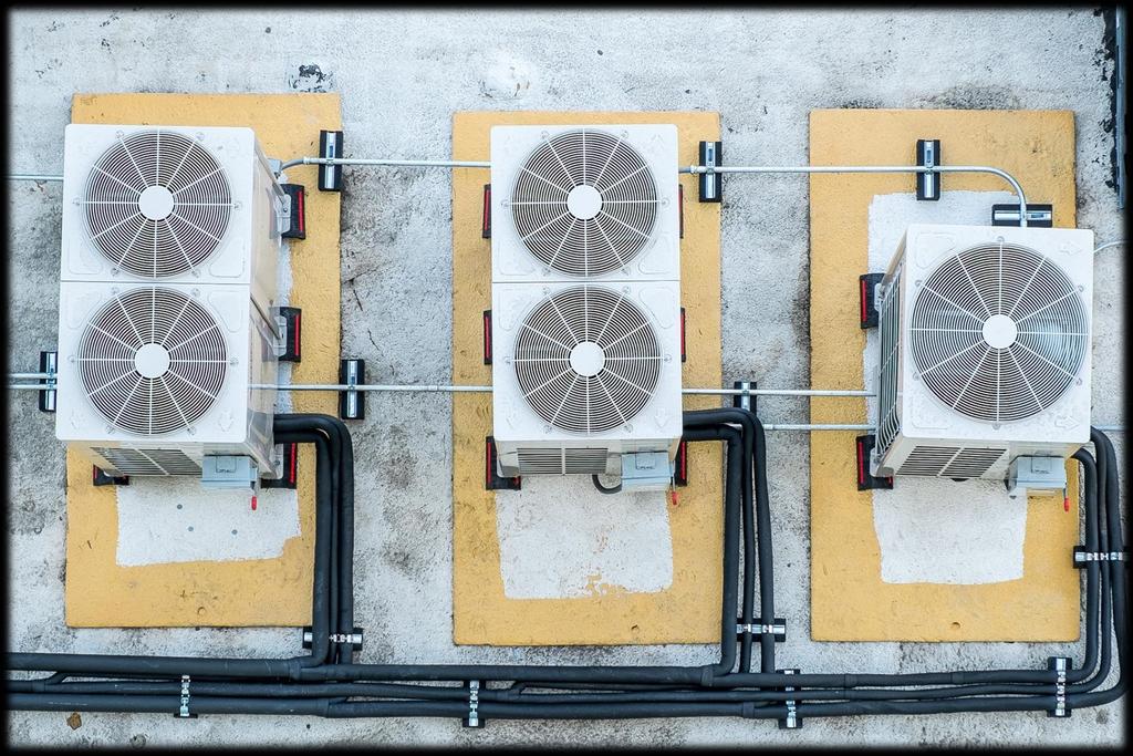
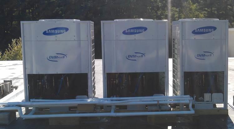
17 Installing Outdoor Unit - Securing The outdoor units must be secured to the building or ground, especially in areas with high winds The systems in this example have structural bracing to prevent the units from tipping over Vibration isolation should also be considered when placing units on a rooftop 17

18 Installing Outdoor Unit Install the outdoor unit(s) making sure that: Snowfall will not obstruct air flow Prevailing winds will not damage the equipment or diminish performance Building exhaust (bathroom, kitchen, combustion, oxides, sulfur, etc.) are not near The unit(s) are serviceable in the future for maintenance and repair 18
19 Installing Outdoor Unit Do not install outdoor units in direct line of ocean/sea winds to avoid damage. Refer to installation and technical guides for exact specifications Place unit behind the building, a screen, or other obstructions to prevent these direct winds 19


20 Indoor Unit Placement and Recommendations
21 Indoor Units While placing indoor units in the building, keep a good record of indoor unit serial numbers and where they will be physically installed in the building (room number, zone, etc.) Use a floor plan to place the indoor unit serial number sticker on the appropriate rooms or use an installation spreadsheet to log indoor unit locations 203 HP-3 21


22 Indoor Units Later, during setup and commissioning, address setting and unit naming will be quick and easy if good records are kept With SNET Pro 2 Service Software, we can view all indoor units based on their serial number SNET Pro 2 Service Software 22


23 Indoor Units Cassette Unit Clearances 59 minimum from smoke alarms, avoid installing in the direction of supply discharge air 5 from walls and other obstructions 10 from other cassette units 6 or more 23
24 Indoor Units Cassette Unit Clearances An 18 X 18 (minimum) inspection hole is recommended on the pipe side of the unit if installed where pipes will not be accessible after installation This is to allow access to the refrigerant and condensate pipe connections for service and preventative maintenance. Local code may require this 24
25 Indoor Units Ceiling Unit Clearances Ceiling Installation Ceiling units can be installed under the ceiling or on a wall (low-wall near floor) Maintain 12 minimum clearance on sides and 2 on back 12 min. 12 min. 12 min. 2 min. 25
 12 min. 12 min. Note: Install unit high enough from floor to prevent damage from brooms, feet, vacuums, etc.")
26 Indoor Units Ceiling Unit Clearances Wall Installation When hanging on the wall, use supplied hanging brackets Wall hanger hook (X2) 12 min. 12 min. Note: Install unit high enough from floor to prevent damage from brooms, feet, vacuums, etc. 26

27 Indoor Units Ceiling Unit Clearances Wall Installation Make sure unit does not slope away from the drain pan outlet once hung 27
28 Indoor Units Concealed Floor Standing Unit Placement Allow sufficient inlet air when concealing the indoor unit 6,000 ~ 12,000 Btu/h: 28 3/4 8,000 ~ 24,000 Btu/h: 39 3/4 28

29 Indoor Units Floor Standing Unit Clearances 6 7/8 minimum 29
30 Indoor Units Ducted Unit Clearances View from bottom Samsung recommends installing an access under duct units for future service and replacement if unit is installed in an inaccessible area (ex: above sheetrock) Samsung also recommends installing a service access door on the PCB and pipe side for future maintenance and inspection providing at least 20 of clearance (verify NEC compliance) 30


31 Indoor Units Ducted Unit Clearances Building Ceiling material Keep 3/4 minimum between a duct unit and the structure above and ceiling material below to prevent noise transmission If humidity of duct unit installation is over 80%, additional insulation of the indoor unit may be necessary (3/8 minimum) 31
32 MCU Clearances 10 minimum Remember, you may need to service the MCU which may require access through the top 32
33 MCU Clearances PCB Inlet side Outlet side Top view 33


34 MCU Clearances Install MCU s in an area where sounds can be tolerated Ideal locations include above ceilings in hallways, bathrooms, mechanical rooms, storage areas, etc. Never install above quiet areas like guest rooms, patient rooms, sleeping quarters, living spaces, or individual office s 34 34
35 Basic Sizing Bounce Back Make sure sufficient space is provided in front of high-wall units to allow air to distribute as designed throughout the space. This is done to avoid a bounce back situation that is similar to short cycling which effects temperature control and decreases equipment life Too Close 35

36 Basic Sizing Bounce Back Example While operating, the louver will direct air up and down. In this example, the wall-mounted unit will create a bounce-back effect as the air is directed at the top of the shelving causing sporadic operation and uncomfortable occupants 36

37 Basic Sizing Bounce Back in a small room Example: Approximately 6 X 10 3 X 24,000 Btu/h wall units Supply air direction pointed toward other units in a small space 6 tons total specified capacity Even with a high load, the likelihood of bounce-back is very high The equipment is designed for comfort cooling/heating, not heavy machinery cooling 37


38 Basic Sizing Bounce Back Example Too close for comfort 38

39 Wall mounted unit guidelines NOT PTAC s - Indoor units MUST be installed a minimum of 5 feet from the floor 39
 Wall Bracket")
40 Wall Unit Clearances Mount wall bracket (included) to wall Ensure that unit is secured to framing or appropriate anchors are used to support the weight of the unit Maintain the following clearances around the wall unit 5 minimum (Rear view of wall unit) Wall Bracket 40

")


41 Installing wall mounted unit Gently rotate line copper pipes to the required position (right, left, bottom, or back sides) Locate condensate hose and tape it to line set BELOW refrigerant lines keeping it as low as possible Suction Liquid Mounting plate Drain hose 41

42 Installing duct and cassette units Use provided template to mark anchor position in ceiling Install anchors and threaded rods ensuring the weight of the unit can be supported 42
43 Installing duct and cassette units Use provided rubber vibration absorbers (included with most units) to help reduce vibration resonance (6 and 8 ton HSP units have larger absorbers included) Install 2 nuts on the bottom and tighten together to ensure safety of occupants below 43

44 Installing ducted units Basic filtration is supplied with the unit Field installed filtration is recommended - either at the unit or installed at the return air grille 44


45 Installing ducted units Return air ductwork can be either free or ducted to the rear or bottom as required ductwork added to the return will need to be subtracted from total length of ducting on the system 45


46 After indoor units are suspended and connected, protect from dust and debris with included covers Never operate indoor units during construction as this can damage indoor unit pumps and coils 46
47 External EEV s and Heat Recovery MCU s Specifications and information contained are subject to change without notice. Always refer to install manuals provided with equipment and controls before installation. 47
48 Refrigerant Piping Samsung piping guidelines and restrictions must be strictly adhered to Failure to follow Samsung piping guidelines may result in decreased capacity, poor performance, equipment damage, and/or premature failure 48


49 Piping Layout (Heat Pump) Heat pump refrigerant systems will consist of copper pipe and Samsung Y-joints and/or headers Aluminum pipe is NOT allowed Y joint only Y joint with header joint 49


50 EEV Kits (for under-ceiling units only) EEV kits are selected based on connected indoor unit capacity Connectable Indoor Unit Quantity Model Number Connectable Indoor Unit Capacity Compatibility MXD-E24K132A 1 X 12,000 BTU/H + 1 X 18,000 24,000 BTU/H 2 unit MXD-E24K200A 2 X 12,000 BTU/H MXD-E32K200A MXD-E24K232A 2 X 18,000 24,000 BTU/H 2 X 12,000 BTU/H + 1 X 18,000 24,000 BTU/H Heat Pump Systems Only 3 unit MXD-E24K300A MXD-E32K224A 3 X 12,000 BTU/H 1 X 12,000 BTU/H + 2 X 18,000 24,000 BTU/H MXD-E32K300A 3 X 18,000 24,000 BTU/H 1 unit MEV-A24SA MEV-A32SA 12,000 BTU/H 18,000 24,000 BTU/H Heat Pump or Heat Recovery Systems 50
51 Piping Layout (Heat Recovery) Heat recovery refrigerant systems will consist of copper pipe, MCU s, and Samsung Y-joints Aluminum pipe is NOT allowed External EEV External EEV 4 Port External EEV 4 Port 4 Port 4 Port 6 Port 4 Port 51
 Subcooler for each port Liquid in")


.")
52 Heat Recovery MCU s Suction to indoor units Liquid to indoor units Subcooler EEV (480 step) Subcooler for each port Liquid in High pressure gas in Pressure equalization EEV to reduce noise during mode change Heating solenoid for each indoor unit Suction in Cooling solenoid for each indoor unit (Top view without cover) Mandatory for heat recovery systems. 3 pipes in from outdoor unit(s), 2 pipes out to indoor units. 2, 4, and 6 zone options (6 port pictured). MCU model details will be covered later in the presentation. 52
53 MCU connection of large indoor units Additional fittings are included to connect 2 ports of the MCU to higher capacity units ( 36,000 Btu/h) with the MCU models listed below. MCU-S4NEE1N will include 2 X liquid and 2 X suction flare Y-joints MCU-S4NEE2N will include 2 X liquid and 2 X suction Y-joints MCU-S6NEE1N will include 3 X liquid and 3 X suction flare Y-joints MCU-S2NEK1N will require part number DB A (not included) when connecting 1 indoor unit to 2 MCU ports that is over 48,000 Btu/h (48,000 Btu/h and smaller can connect to a single port). MCU-S4NEE1N, MCU-S4NEE2N MCU-S6NEE1N MCU-S2NEK1N A B C D A B C D E F A B When twinning 2 ports together, the 2 sets of ports must be beside each other (ex: A&B) 53

54 More details 54 on following page DVM S MCU-S4NEE1N connection examples Model: MCU-S4NEE1N Model: MCU-S4NEE1N Model: MCU-S4NEE1N 18,000 Btu/h 18,000 Btu/h 30,000 Btu/h 76,000 Btu/h 48,000 Btu/h 48,000 Btu/h 48,000 Btu/h 48,000 Btu/h

55 MCU-S4NEE2N connection examples Model: MCU-S4NEE2N Model: MCU-S4NEE2N Model: MCU-S4NEE2N 76,000 Btu/h 36,000 Btu/h 12,000 Btu/h 96,000 Btu/h 96,000 Btu/h 96,000 Btu/h 55
56 Refrigerant Piping Limitations Specifications and information contained are subject to change without notice. Always refer to install manuals provided with equipment and controls before installation. 56
57 Main Pipe When discussing pipe limitations, the term main pipe refers to the set of pipes that enter the building from the outdoor unit to the first Y-joint, EEV kit, or MCU (single MCU systems) Equivalent pipe length accounts for elbows in the liquid pipe. Equivalent length of elbows for each pipe diameter will be discussed later in this course (HR with only one MCU) 57
58 Maximum Piping Lengths Maximum 656 actual, 722 equivalent, from the outdoor unit(s) to the farthest indoor unit(s) (heat pump and heat recovery) 58
59 Maximum Piping Lengths For heat pump systems, if this distance from the outdoor unit(s) to the farthest indoor unit is over 295, increase the liquid and suction pipes one size for the main pipe section DVM Pro design software will do this for you automatically Greater than 295 (less than 656 ) Main Pipe 59
60 Maximum Piping Lengths For heat recovery systems, If this distance is from the outdoor unit(s) to the farthest indoor unit is over 295, increase the liquid pipe one size for the main pipe section DVM Pro design software will do this for you automatically Main Pipe Greater than 295 (less than 656 ) Explanation on following page 60
61 Maximum Piping Lengths For heat recovery systems, maximum 148 from the first branch to the farthest indoor unit If this length is over 148 while designing a system, consider putting the first branch joint further into the building 61
62 Maximum Piping Lengths (Heat Recovery, 1 MCU) b, c, d, e, f, g
63 Maximum Piping Lengths Maximum 295 from the first Y-joint to the farthest indoor unit (heat pump systems) If the distance from the first branch joint to the farthest indoor unit is 149 increase the main branch liquid and suction pipes from the first branch joint throughout the system (sections: a,b,c,d,e,f,g below). DVM Pro design software will do this for you automatically a b c d e f g 63
64 Maximum Piping Length Between Indoor Units (a+b+c+d+e+f+g+p) (a+h) 148 Maximum 148 from the closest to the farthest indoor unit Example from above: h+b+c+d+e+f+g+p 148 if unit 1 is the closest to the outdoor unit and unit 8 is the farthest 64

65 Maximum Piping Lengths Minimum 3 between each Y-joint If Y-joints are too close noise and turbulence can occur creating noise and potential pipe damage Minimum 3 65
")
66 Maximum Piping Lengths Maximum 149 feet from a Y-joint to an indoor unit (as long as no other restriction has been exceeded) 66
67 Maximum Piping Lengths Vertical Separation Vertical separation refers to the vertical distance between 2 units 8 8 When looking at vertical separation restrictions horizontal pipe lengths are not considered, just installed height differences Example: 8 story building 8 floors
68 Maximum Piping Lengths Heat Pump Vertical Separation Standard maximum height difference from outdoor unit to lowest indoor unit: When condenser is above indoor units (ex: rooftop): 164 When condenser is below indoor units (ex: ground level): 131 Maximum height difference from outdoor unit to lowest indoor unit with pipe modification: When condenser is above indoor units (ex: rooftop): 360 Maximum height difference between indoor units: 164 (exceptions exist, explained on next page) If vertical separation is 164 but 360, contact Quietside for modified pipe design with PDM kit. (Pressure Drop Modulation) When vertical separation is >295 a PDM kit is required. Use Samsung s DVM E-Solution software to select PDM kit 68
, maximum vertical separation between the highest indoor unit")

69 Vertical Separation Exception Heat Pump AM0**HNQDCH/AA If Neo Forte indoor units with internal EEV are installed (AM0**HNQDCH/AA), maximum vertical separation between the highest indoor unit and lowest indoor unit = max. This exception exists to prevent refrigerant noise from the internal EEV since it is not concealed/recessed into the ceiling like cassette and duct unit EEV s. 69
70 Maximum Piping Lengths Heat Recovery Vertical Separation Maximum height difference from outdoor unit to lowest indoor unit (H1): When condenser is above indoor units (ex: rooftop): 164 (standard), 360 with PDM kit When condenser is below indoor units (ex: ground level): 131 Maximum height difference between indoor units (H2): 49 Maximum height difference between MCU s (H3): 49 H3 H1 H2 If vertical separation is 164 but 360, contact Quietside for modified pipe design with PDM kit. When vertical separation is >295 a PDM kit is required. Use Samsung s DVM E-Solution software to select PDM kit 70
71 Maximum Piping Lengths - Between Outdoor Modules 33 max. 33 max. 33 max. (Outdoor connections shown vertical for simple viewing. All outdoor fittings must be installed horizontally.) r, s, t 33 actual length (43 equivalent) from the first Tee to each outdoor module Outdoor units must have no vertical separation between modules 71
72 Maximum Piping Lengths Maximum pipe length between single unit and EEV: 6.5 Must install vertical as pictured on this page Install included strainer on the inlet side Never extend interconnect wire MEV-A23SA, MEV-A32SA IN OUT Included strainer 6.5 max. Strainer with flare connections (provided) To under-ceiling unit 72

73 Maximum Piping Lengths Maximum pipe length between multi unit EEV kit and indoor unit: 65 each MXD EEV kits are for heat pump systems only 65 max. MXD-A**K***A 65 max. 65 max. 73
74 Piping Equivalent Lengths Below are values that Samsung uses for equivalent pipe lengths for an elbow Each liquid pipe diameter will have a different equivalent pipe length value Pipe Size (ø O.D.) Equivalent length (feet) 3/ / / / / Long radius elbows only 1 1/ / Y-Joint 1.64 Header Joint
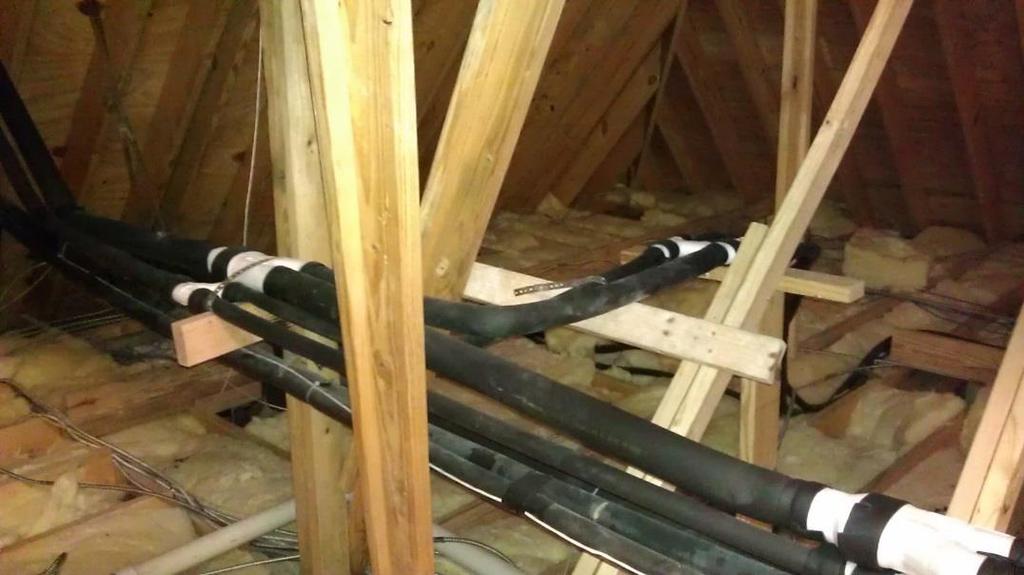
75 Piping Around Obstacles When an obstacle, such as an I-beam or concrete T, is in the path of the planned refrigerant pipe run, it is best practice to route the pipe over the obstacle. If adequate space is not available to route the insulated pipe over the obstacle, then route the pipe under the obstacle. In either case, it is imperative the length of the horizontal section of pipe above or below the obstacle be a minimum of three (3) times the longest vertical rise (or fall) at either end of the segment. 3 X (minimum) X X 3 X (minimum) Over obstacle Under obstacle 75


76 Refrigerant Pipe Installation Specifications and information contained are subject to change without notice. Always refer to install manuals provided with equipment and controls before installation. 76

 1/4 to 5/16 service hose adapter")

 Torch Set Nitrogen")
")
77 Pipe Installation Tools and Steps Ensure that quality, proper tools are available during installation Manifold Set (dedicated for R410A) 1/4 to 5/16 service hose adapter Flaring Tool (45º Flare) Tubing Cutter De-burring Tool Micron Gauge Torque Wrench Set W/Backup Wrenches Vacuum Pump Check Valve (For Vacuum Pump) Torch Set Nitrogen and Regulator Nitrogen Flowmeter Micro Leads Hand Tools Refrigerant oil (POE oil) Electronic scale 77
78 Pipe type Soft copper can be used for pipe sizes up to 5/8 Pipe connections at most indoor units does not exceed 5/8, this allows for flare connections (HSP 6 and 8 ton units have larger suction ports that requires brazing). 3/4 and above must be hard-drawn, rigid pipe Pipe Size (ø O.D.) Pipe Thickness (inches) Material 1/ /8 1/ / / /8 1 1/ /4 1 3/ / / C1220T-O (annealed) C120T-1/2H (drawn temper, hard-drawn) 78
.")
79 Refrigerant Piping Remove copper burrs after cutting pipe with de-burring tool (especially before flaring of pipe). Make sure to point the pipe downward to prevent entry of removed copper. 79


80 Refrigerant Piping Prevent entry of foreign substances by capping and/or taping the ends of refrigerant pipes 80

81 Refrigerant Piping To prevent buildup of non-condensable substances in the refrigerant pipes, low flow, dry nitrogen must be used during brazing of copper connections This displaces oxygen and prevents oxides from forming Failure to use nitrogen while brazing will cause accumulation of oxides at the compressor, various strainers, and expansion valves impacting performance and causing premature failure Without nitrogen flow With nitrogen flow 81
 of dry nitrogen If you are having difficulty maintaining this, partially cover the end of the pipe with tape to maintain pressure.")
82 Refrigerant Piping Connect a nitrogen tank near the point that will be brazed Using a flow regulator, maintain 1.76 ft³/hr ( 2 3 PSI) of dry nitrogen If you are having difficulty maintaining this, partially cover the end of the pipe with tape to maintain pressure. If flow is too low, this will not effectively prevent oxide formation If flow is too high, it will be difficult to make a quality brazed connection Maintain flow after brazing is complete until pipe is no longer hot 82
83 MCU s (HR Only) MCU refrigerant connections are flare and braze type Take precautions to prevent MCU damage by overheating 83
 have a")


84 Refrigerant Piping Larger HSP units (AM072FNHDCH/AA and AM096FNHDCH/AA) have a flare fitting on the liquid line connection Detach Flare First! The suction line must be brazed The unit ships with a copper cap that needs to be removed with a torch REMOVE THE LIQUID SIDE FITTING BEFORE SWEATING OFF THE SUCTION LINE CAP Failure to do this first can cause injury. 84


85 Refrigerant Piping Heat Exchanger While brazing the suction line, take care not to overheat the pipe or allow a flame to enter the cabinet EEV There are sensors right behind the cabinet door that are easily damaged Fan Motor Eva out Sensor Indoor temp Sensor Gas pipe Liquid pipe Eva in Sensor Removal of the EVA out sensor while brazing is recommended to prevent damage Use of heat dissipating products and wet cloths is recommended to protect the cabinet and other components 85
86 Tee and Y Installation 86


87 Outdoor Joint (HP and HR) Some fittings have adjustable ends to facilitate easy field installation of multiple pipe sizes with a single Y-joint 3/8 5/8 87
 Horizontally installed Vaporized refrigerant leans to upper direction of Y joint.")
88 Y Joint Installation Samsung Y-Joint fittings will include necessary reducers to connect to various pipe sizes All Y-joints must be installed horizontally level (within 15º of horizontal plane) Horizontally installed Vaporized refrigerant leans to upper direction of Y joint. Install within ± 15 of horizontal plane 88
89 Y Joint Installation Samsung Y-Joint fittings can be installed vertically Ensure that there is minimum 20 between an elbow and a Y-joint before turning upward or downward Y-joints must be installed vertically level or horizontally level, never at upward/downward slope Vertically installed Allow 20 minimum between elbow and Y joint when installing vertically 89

90 Y Joint Installation 90


91 Y Joint Installation If the refrigerant fitting does not have a groove to stop the copper pipe from entering too far, measure and mark the pipe at 5/8 from the end The pipe should not be inserted past this point Care needs to be taken to ensure that the refrigerant pipe does not get pushed into the Y joint too far before brazing If inserted too far this can cause turbulence, noise, and potential vibration 91

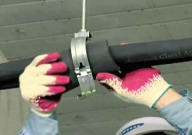
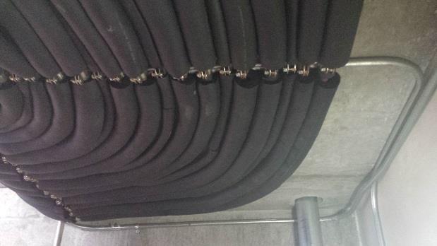
92 Y Joint Installation 20 minimum between a Y-joint and an elbow on both ends 20 min. 92
 can only connect to a single indoor unit, never a Y-joint or 2/3 port EEV kit")
93 Header Joint Installation Header joint kits will include a liquid fitting, suction fitting, reducers and insulation The liquid fitting is open at both ends to allow left or right installation Install the included plug on the open end after the incoming refrigerant pipe is connected Plug The outlets (liquid and suction) can only connect to a single indoor unit, never a Y-joint or 2/3 port EEV kit 93

 Inlet Outlets LEVEL NEVER INSTALL VERTICALLY Cap any unused")
94 Header Joint Installation Liquid fitting The liquid pipe must be installed horizontally level Inlet Inlet LEVEL The outlet ports must be on the bottom side of the liquid fitting with the outlets horizontally level (within 15º in either direction) Inlet Outlets LEVEL NEVER INSTALL VERTICALLY Cap any unused ports 94
95 Header Joint Installation Suction gas fitting The suction pipe must be installed horizontally level (within 10º in either direction) with the outlet ports in a horizontal position (do not point upward or downward) Back of suction header fitting once installed Suction header outlet ports must be horizontally level (within 15º in either direction) Inlet Outlet NEVER INSTALL VERTICALLY Cap any unused ports 95
96 Pipe Support Support headers after insulating (Suction outlets pointing down) 96
97 Refrigerant Piping - Flaring Proper flare techniques are necessary for a properly installed system Make sure the flare nut (provided with the indoor units) is on the copper before a flare is made Samsung requires that all flare joints made in the field are done with a tool that creates a 45⁰ flare 97

98 Refrigerant Piping Types of flare tools 98

99 Refrigerant Piping - Flaring Make sure the copper pipe depth is within Samsung recommendations noted below The depth is referring to the distance between the die and the end of the copper tube. 99
100 Refrigerant Piping - Flaring After making a flare, inspect to ensure a proper connection can be made to the indoor unit Apply POE refrigerant oil (small amount) to inside of the flare, on the threads, and on the face of the brass male fitting to facilitate proper tightening and seal of the flare nut 100
101 Refrigerant Piping - Flaring Over tightening is a very common cause of leaks Torque the flare nut to the specifications listed in the indoor unit installation manuals Pipe Diameter (OD) Torque (ft./lbs.) 1/ / / / While tightening, prevent pipe damage by supporting the male side with a wrench pushing in the opposite direction 101


102 Outdoor Units Piping Main refrigerant pipes can enter the outdoor cabinet through the front access door or through the bottom of the unit 102


103 Take necessary precautions to avoid damaging outdoor unit while brazing Use wet towels or other heat dissipating products to protect equipment and components If temperature sensors are near the brazing areas, remove and replace after the brazed area has cooled. Heat Pump Heat Recovery 103
 Heat Pump and Heat")

104 T Installation (outdoor units only) Heat Pump and Heat Recovery Systems * All fittings must be installed horizontally level 104

105 T Installation (outdoor units only) Heat Recovery Systems * All fittings must be installed horizontally level 105
106 Outdoor Units Piping Accumulation of oil Refrigerant piping should be the same level or lower than the outdoor unit(s). Examples on following pages 106

.")

107 Outdoor Units Piping Refrigerant piping should be the same level or lower than the outdoor unit(s). Supply pipes are higher than the outdoor unit modules. Example on following page 107


108 Outdoor Units Piping Refrigerant piping should be the same level or lower than the outdoor unit(s). 108


109 Outdoor Units Piping Refrigerant piping should be installed in a horizontal direction. Install horizontal 4 Inches Minimum 109

110 Outdoor Units Piping Refrigerant piping should be connected with side direction. As the pipes approach the outdoor units, it needs to run parallel to the front of the modules Unbalancing of Ref. & oil distribution Refrigerant will flow more in one direction 110
111 Outdoor Units Piping Install a vertical trap between SUB1 and SUB2 outdoor modules when over 78 from second outdoor Tee Less than 40 7 ¾ Over

112 Pipe Support 112


113 Pipe Support Ref pipes through 1, supports must be spaced no more than 48 inches apart If the ref pipe size is larger than 1, the refrigerant line supports must be spaced no more than 60 inches apart 113
")
114 Pipe Support Install a hanger before and after each branch joint to prevent sagging and stress on the brazed joints (within 18 of the inlets and outlets) 114
115 Copper Expansion and Contraction Under normal operating conditions, the vapor pipe temperature of a DVM S system can vary as much as 280 F. With this large variance in pipe temperature, the designer must consider pipe expansion and contraction to avoid pipe and fitting fatigue failures. If the pipe is mounted in free air space, no natural restriction to movement is present if mounting clamps are properly spaced and installed. When the refrigerant pipe is mounted underground in a utility duct stacked among other pipes, natural restriction to linear movement is present. In extreme cases, the restrictive force of surface friction between insulating jackets could become so great that natural expansion ceases and the pipe is fixed in place. In this situation, opposing force caused by change in refrigerant fluid/vapor temperature can lead to pipe/fitting stress failure. 115
116 Copper Expansion and Contraction The refrigerant pipe support system must be engineered to allow free expansion to occur. When a segment of pipe is mounted between two fixed points, provisions must be provided to allow pipe expansion to naturally occur. The most common method is the inclusion of expansion Loop or U-bends Each segment of pipe has a natural fixed point where no movement occurs. This fixed point is located at the center point of the segment assuming the entire pipe is insulated in a similar fashion. 116
117 Copper Expansion and Contraction The natural fixed point of the pipe segment is typically where the expansion Loop or U- bend should be. Linear pipe expansion can be calculated using the following formula : LE = C x L x (Tr Ta) x 12 LE = Anticipated linear tubing expansion (in.) C = Constant (For copper = 9.2 x 10⁻⁶ in./in. F) L = Length of pipe (ft.) Tr = Refrigerant pipe temperature ( F) Ta = Ambient air temperature ( F) 12 = Inches to feet conversion (12 in./ft.) From the anticipated expansion data table on the next slide, find the row corresponding with the actual length of the straight pipe segment. Estimate the minimum and maximum temperature of the pipe. In the column showing the minimum pipe temperature, look up the anticipated expansion distance. Do the same for the maximum pipe temperature. Calculate the difference in the two expansion distance values. The result will be the anticipated change in pipe length. 117
118 Copper Expansion and Contraction To find the anticipated expansion value: 1. From the table below, find the row corresponding with the actual feet of the straight pipe segment. 2. Estimate the minimum and maximum temperature of the pipe. 3. In the column showing the minimum pipe temperature, look up the anticipated expansion distance corresponding to the segment length. Do the same for the maximum pipe temperature. 4. Calculate the difference in the two expansion distance values. The result will be the change in pipe length. Pipe Length (ft.) Linear Thermal Expansion of Copper Tubing in Inches. Fluid Temperature F Pipe length baseline temperature = 0 F The Engineers' Toolbox ( - Expansion of Carbon, Copper and Stainless Steel Pipe 118
119 Copper Expansion and Contraction General Example A DVM S system is installed and the design shows that there is a 120 feet straight segment of tubing between a Y-branch and an indoor unit. In heating, this pipe transports hot gas vapor to the indoor units at 120 F. In cooling, the same tube is a suction line returning refrigerant vapor to the outdoor unit at 40 F. Look up the copper tubing expansion at each temperature and calculate the difference. Vapor Line Transporting Hot Vapor: 120 ft. pipe at 120 F = 1.68 in. Transporting Suction Vapor: 120 ft. pipe at 40 F = 0.48 in. Anticipated Change in Length: 1.68 in in. = 1.20 in. Liquid Line The liquid temperature remains relatively the same temperature; only the direction of flow will reverse. Therefore, no significant change in length of the liquid line is anticipated. When creating an expansion joint, the joint height should be a minimum of two times the joint width. Use soft copper with long radius bends on longer runs or long radius elbows for shorter pipe segments. Using the anticipated linear expansion (LE) distance calculated, look up the Expansion Loop or U- bend minimum design dimensions. If other types of expansion joints are chosen, design per ASTM B- 88 Standards. 119


120 Copper Expansion and Contraction General Example For the example on the previous page, if anticipated change in length = 1.20 in, and the vapor pipe is 1 1/4, an expansion loop or U-bend would be needed with a 20 radius. Coiled Expansion Loops and Offsets R1 = Centerline Length of Pipe. L2 = Centerline Minimum Radius (inches). 120

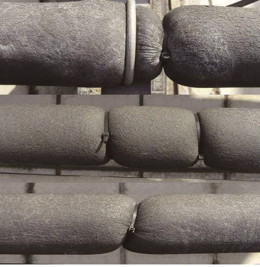
121 Vertical Pipe Support When installing refrigerant pipes vertically, support the pipes according to the table below. Height Fixing interval Example 1 Less than 50 Support pipes every 16 minimum Protect pipe from clamp with tape or rubber 2 Higher than 50 Support pipes every 16 minimum Install a down stopper every 3 floors or every


122 Vertical Pipe Support Attaching the down stopper to the vertical pipe Braze the down stopper to the pipe while flowing low pressure nitrogen through the pipe Secure the support to the structure and to the pipe 4. Insulate the pipe and support appropriately 122
123 Isolation Valves Specifications and information contained are subject to change without notice. Always refer to install manuals provided with equipment and controls before installation. 123
124 Isolation Valves Isolation valves are not required but recommended Installation of refrigerant isolation valves will make any future service or replacement much easier Installation may also allow for system operation during any unit replacement or service 124


125 Isolation Valves Full-port valves are mandatory if isolation valves are installed Valves with a service port access are recommended for pressure check and vacuum drying operations When valve is open, the ball opening is the same diameter as the inside pipe diameter 125
.")
126 Isolation Valves Heat Recovery Systems When installing isolation valves before MCU s to isolate an MCU and connected indoor units, install the valves right after the connected Y-joint (explanation on following pages). Isolation valves installed immediately after Y-joint Isolation valves installed immediately before MCU MCU 1 X3 MCU 1 To indoor units To indoor units X3 Isolation X3 X3 MCU 2 X3 MCU 2 To indoor units To indoor units MCU 3 MCU 3 X3 To indoor units To indoor units 126
.")
127 Isolation Valves Heat Pump Systems When installing isolation valves on heat pump systems, install the valves immediately after the Y- Joint (explanation on following pages). Isolation valves installed immediately after Y-joint Isolation X2 X2 X2 X2 X2 Isolation valves installed immediately before indoor unit X2 X2 X2 X2 Isolation X2 127
128 Pressure Test, and Pipe Insulation Specifications and information contained are subject to change without notice. Always refer to install manuals provided with equipment and controls before installation. 128


129 Leak Test - Manifold Connection All refrigerant pipes must be connected to your manifold during leak testing and vacuum process (liquid, suction, and high pressure gas) Heat Pump Heat Recovery Service port Pressure gauge Example: Pressure checking before outdoor unit is installed during and after pipe/idu installation. 129

130 PRESSURE PSI DVM S Leak Test PSI Pressure system to 75 psi for 5 minutes Pressure system to 220 psi for 5 more minutes PSI 3. Pressure system to 590 psi for 24 hours PSI 145 PSI 4. Bring back down to 145 psi and leave until ready to begin vacuum process 5 min 15 min 24 hours Hold until ready to vacuum TIME (temperature difference calculation on next page) 130
131 Leak Test Ambient temperature changes Make a note of ambient temperatures after pressurizing system up to 590 PSI After 24 hours if ambient temperatures change, this can effect the pressure within the refrigerant system For every 1 F, a pressure change of psi can be expected. = Pressure when adding nitrogen + ((Current temperature-initial temperature) X 0.805) EXAMPLE: If It was 85º F when you initially charged with dry nitrogen, and you got the pressure up to 583 psi, and when you returned after 24 hours the ambient temperature is 82º F, the pressure that should be present is: = 583 psi + ((82-85) X 0.805) = 583 psi + (-3 X.0805) = psi 131
132 Joint Insulation To prevent condensation formation, seal all seams of Y-joint and header insulation Seal pipe insulation to header and Y-joint insulation 132

133 Joint Insulation Install provided header joint insulation If any ports were not used, insulate to prevent condensation Seal all seams of provided insulation Seal seams of header insulation to pipe insulation 133

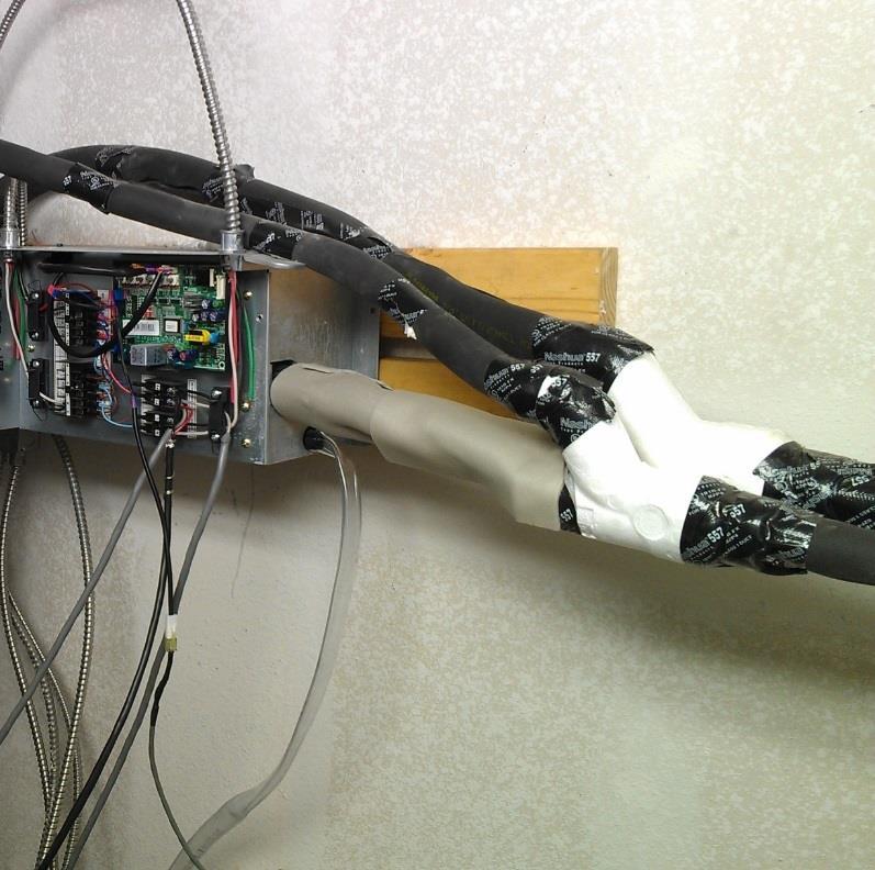
134 Indoor Unit Connection Insulation Wrap the thick pipe insulation that came with the indoor unit around the liquid and suction pipes (individually wrapped) with the seam on the top of the pipes first Then wrap the adhesive-back insulation around the thick insulation Attach provided wire ties around the insulation as pictured below. No copper or brass should be exposed 134

135 System Evacuation and Additional Refrigerant Specifications and information contained are subject to change without notice. Always refer to install manuals provided with equipment and controls before installation. 135


136 System Evacuation What is a Triple Evacuation? Is it timed? Is it a process? 136
137 System Evacuation 1. Connect a vacuum pump with new oil 2. Connect an accurate micron gauge to monitor vacuum status 3. Evacuate down to 5000 microns 4. Pressurize with dry nitrogen to 3 psi 5. Hold pressure for 10 minutes 137
138 System Evacuation 6. Release nitrogen 7. Evacuate down to 2000 microns 8. Pressurize with dry nitrogen to 3 psi 9. Hold pressure 15 minutes 10. Evacuate to 300 microns and hold for 60 minutes. Vacuum process may require multiple vacuum breaks with dry nitrogen Vacuum pump operation duration must be over 2.5 hours. When the ambient temperature is below 32⁰ F, extra care must be takes to ensure that the pipe system remains moisture free during and after installation. If the above mentioned micron levels cannot be achieved check hose integrity, seal integrity and change your vacuum pump oil. 138
139 Additional Refrigerant At this point the system is ready for the additional refrigerant Use a quality digital scale to accurately weigh in the calculated amount of refrigerant Additional refrigerant amounts are based on linear feet of liquid line piping for each diameter, EEV kits, etc. Samsung s DVM Pro software is a helpful tool to quickly calculate this value Add additional refrigerant before releasing the factory charge from the condensing unit 139
140 Condensate Drain Piping Specifications and information contained are subject to change without notice. Always refer to install manuals provided with equipment and controls before installation. 140
141 Drain Pipe Installation Single Cassette and Samsung Duct Units With Internal Pump Current cassette models have a maximum pump head of 29 from the bottom of the unit All drain pipes must be insulated throughout the building A vent can be installed at the top dead point to facilitate proper drainage if needed Hangers must be installed every 40 to 60 minimum to prevent accidental traps At the top of the trap a tee or elbow is necessary to prevent debris from falling into the drain pipe 141
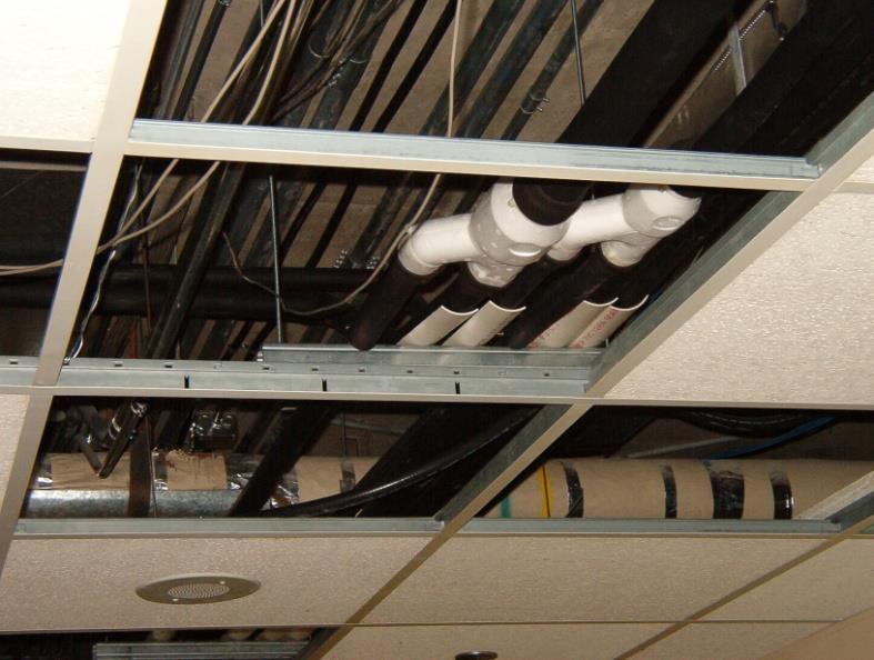
142 Drain Pipe Installation Single Cassette and Samsung Duct Units With Internal Pump The individual drain lines must tap into the main drain line from the top, not the side or bottom (example on next page) There must be a main drain pipe vent every 32 to 50 Individual drain vents may be necessary to prevent water leakage Make sure the main drain line is sized properly to handle the volume of condensate from multiple units. Same height 142

143 Drain Pipe Installation Tapping Into Top Of Common Drain Failure to tap into the main drain pipe from the top will cause: check valve failure, poor or no drainage, and/or water leaks Premature pump failure can also occur 143
 Never connect multiple units together that are not the same height to prevent leakage in the event of a main drain pipe")
144 Drain Pipe Installation Slim Duct (AM0**FNLDCH/AA) Slim Duct model unit drain pans are on the positive side of the blower Single units do not need a trap to prevent leaks, but needs a trap or vent at some point to prevent gasses from entering (verify local and state codes) Never connect multiple units together that are not the same height to prevent leakage in the event of a main drain pipe blockage Single Slim Duct Unit Multiple Slim Duct units connected to a common drain line 144

145 Drain Pipe Installation MSP and HSP Ducted MSP and HSP units require a P-trap to allow proper drainage from the unit Make sure the main drain pipe can handle the volume of condensation from multiple units Only connect units to a single main drain pipe that are suspended the same height Prime P-traps before operation to prevent condensate pan overflow 145

146 MCU drain connection If proper drain pitch is not possible, consider using a common condensate pump or a smaller single unit condensate pump. 146
147 Wall Unit Condensate Pump Installation Specifications and information contained are subject to change without notice. Always refer to install manuals provided with equipment and controls before installation. 147


148 Condensate pumps wall mounted, ceiling, and floor standing units Cassette units have condensate pumps built in Ducted units have Samsung condensate pumps available or built in Aspen and Blue Diamond pumps are available through Quietside/Samsung for wall mounted units, MCU s, floor standing units, and ceiling units. Aspen ASP-MO-UNIV Blue Diamond BD-BLUE
149 External Condensate Pumps Basic Configuration Condensate water flows into the reservoir from the indoor unit The float in the reservoir activates the pump through the float signal wire (this varies based on pump type) The pump turns on and draws water from the reservoir through the interconnect water tube Condensate water is discharged from the pump Water tube Vent tube 1 Float Drain line from indoor unit 2 Reservoir Float switch signal wire 3 Water tube Pump 4 Power and float switch isolated contacts 149
150 Condensate pumps wall mounted units There are 2 methods for disabling a Samsung wallmounted unit with condensate pump signal Method 1: Temperature sensor connection Method 2: External contact, 0 volts, signal connection (external contact control) 150
151 Condensate pumps wall mounted units Method 1 METHOD 1 Temperature sensor interruption Use the N.C. (normally closed, purple) and Common (grey) wires from the pump to turn off system in the event of pump failure or drain blockage Do not use this relay to break the high voltage to the indoor unit or wired controller connections Aspen ASP-MO-UNIV Relay wire connection NC: Purple Common: Grey Blue Diamond BD-BLUE230 Relay wire connection NC: Yellow Common: Black (located in grey cable) 151

152 Condensate pumps wall mounted units Method 1 Connect this relay to one of the conductors coming from the indoor temperature sensor located on the front of the evaporator coil and break When there is a failure, loss of temperature sensing will disable the unit 152

153 Condensate pumps wall mounted units Method 2 METHOD 2 External contact signal Locate the external contact control connection wires inside the Neo Forte chassis PCB cover 153

154 Condensate pumps wall mounted units Method 2 Connect the condensate pump s normally closed and common wires to the external contact control connection wires inside the Neo Forte chassis wire cover Black/white wire Cut off red connector and connect to pump relay N.C. and Common Ensure that all connections are properly insulated and secured inside the unit chassis 154
155 Duct Unit Secondary Pan Float Switch Connection Specifications and information contained are subject to change without notice. Always refer to install manuals provided with equipment and controls before installation. 155


156 Duct Unit Float Switch Secondary Pan Float Switch Connection Enable Depending on the installation location, a secondary, external pan may need to be installed under a ducted unit. The following are options for connecting a field-provided float switch to a ducted unit for emergency float detection 156
157 157 Duct Unit Float Switch Secondary Pan Float Switch Connection Example 1 If the duct unit has an internal Samsung condensate pump, connect the secondary pan switch in series with the built-in float on the condensate pump (black 2 pin plug, CN411)


158 158 Duct Unit Float Switch Secondary Pan Float Switch Connection Example 2 If the duct unit does not have an internal Samsung condensate pump, connect the secondary pan switch to the FLOAT-SW plug on the ducted unit PCB. DB A CN83 Pigtail This will require part number DB A (pigtail with plugs) Use the DB A to connect the field-provided, 0 volt, normally closed switch to the PCB. During indoor unit programming, tell the duct unit that there is a condensate pump installed.

159 Duct Unit Float Switch Secondary Pan Float Switch Connection When the contact is opened and not closed shortly thereafter, E153 will display on the wired controller and any central controllers Switch wired to Float input on PCB Secondary pan E
160 Cassette Panel Installation Specifications and information contained are subject to change without notice. Always refer to install manuals provided with equipment and controls before installation. 160


161 1-Way Cassette Panel Installation Adjust the height of the indoor unit in relation to the ceiling with the included guide Situate the panel in the proper direction before lifting up to unit Lift the panel up to the unit guiding the panel hooks into the openings on the 1- way cassette chassis Guide the louver and display wires into the PCB box making sure not to pinch or damage them Push upward until the hooks catch in the provided openings 161

 by supply air outlet")
162 1-Way Cassette Panel Installation With the provided hardware, screw the panel to the unit Take care not to over tighten to prevent damaging the panel Make sure the panel is snug to the ceiling all the way around to prevent moisture issues and air leakage Install white screw covers (3) by supply air outlet louver 162


163 4-Way/Mini 4-way Cassette Panel Installation Adjust the height of the indoor unit in relation to the ceiling with the included guide Situate the panel in the proper direction before lifting it up to unit. There are only 2 directions the panel can attach to the unit because of the 2 panel hooks. The side of the panel with the louver and display wires needs to mount on the same side as the indoor unit s PCB Lift the panel up to the unit guiding the panel hooks into the openings on the 4-way cassette chassis Guide the louver and display wires into the PCB box making sure not to pinch or damage them Push upward until the hooks catch in the provided openings 163


164 4-Way/Mini 4-way Cassette Panel Installation With the provided hardware, screw the panel to the unit Take care not to over tighten to prevent damaging the panel Make sure the panel is snug to the ceiling all the way around to prevent moisture issues and air leakage Plug in the louver and display connectors to the PCB as described earlier 164


165 Cassette Panel Installation Louver (CN805/CN806) Attach the louver and display connectors to the PCB Take care to plug into the correct terminals LOUVER and DISPLAY are printed on the PCB above or below the proper locations Display (CN501) Mini 4-Way Cassette PCB 165

166 High Voltage Wiring Only a licensed electrician should connect power to Samsung DVM S systems 166


167 Main Power Wiring Each outdoor unit needs its own breaker and disconnect (NEC) Indoor units require their own 208/230V 1Ph circuit(s) 167


 Connect high voltage in the control")
168 Main Power Wiring Precautions Use ring connectors for all supply voltage wire connections 460V units have a transformer for 230V internal components (valves, controls, etc.) Connect high voltage in the control box, not at the transformer. 168


 terminals in")


169 DVM Indoor Units Main Power Wiring Indoor Unit Mini 4-Way Cassette AM0**JNZDCH/AA Multi-position AHU Connect the 1Ø/ V circuit(s) to the 1(L) and 2(N) terminals in each indoor unit Ensure the unit is properly grounded well for proper operation and safety Use ring connectors to connect high voltage Do not connect the main ground at the same point where the indoor unit is grounded 169

 to the 1(L) and 2(N)")


 Use")
170 DVM Indoor Units Main Power Wiring - MCU MCU-S4NEE1N power and COM connections Connect the 1Ø/ V circuit(s) to the 1(L) and 2(N) terminals in each MCU and 2/3 zone EEV kit Ensure the unit is properly grounded well for proper operation and safety Additional L/N connections are available to power indoor units (not typically used in North America) Use ring connectors to connect high voltage 170
171 System Communication 171
 MAIN PCB HUB PCB Communication Terminals IPM 1 (inverter PCB) High voltage connection box")
172 System Communication Outdoor Unit Control Box Single Compressor Model Outdoor unit control box NOTE: Outdoor units with 2 compressors will have a second IPM in this location (IPM 2) MAIN PCB HUB PCB Communication Terminals IPM 1 (inverter PCB) High voltage connection box 172
173 System Communication Outdoor Unit Communication Connections F1 / F2 Communication from the MAIN outdoor unit to all indoor units, MCU s, and EEV kits on that refrigerant system (more details on next page) F1 / F2 OF1 / OF2 Communication from the MAIN outdoor unit to the SUB1 and SUB2 outdoor units (only used when the system has more than 1 outdoor unit). OF1 / OF2 R1 / R2 Communication from the MAIN outdoor unit to central control options (DMS2, BACnet, LON, touch controller) R1 / R2 173

 is not necessary Always use 2 X 16AWG, shielded cable for all communication")
174 System Communication F1/F2 Main Communication Cable - F1/F2 F1/F2 (Com 1) is what allows communication between the outdoor unit and the indoor air handlers and MCU s This will be the only point of communication between all units on systems with no upper level controls F1/F2 (Com 1) is system specific (at no time should F1/F2 from one system connect to a separate system) RS485 Communication A separate cable from each piece of equipment inside back to the outdoor unit(s) is not necessary Always use 2 X 16AWG, shielded cable for all communication cables 174
175 System Communication F1/F2 Heat Pump Systems Does not need to be connected in any particular order between all F1/F2 terminals throughout the system in regards to Main address Connect F1/F2 the most efficient way in regards to materials Maximum 3,280 from outdoor to farthest indoor unit. Must connect to all indoor units and 2/3 port EEV kits (if installed) 175


176 System Communication F1/F2 Ground the bare wire in the outdoor unit on a separate point than the main electrical service ground Bond this wire throughout the system to carry the ground throughout the system Do not ground at indoor units, outdoor unit only This will allow any interference to be eliminated Do this for all communication points (F1/F2, R1/R2, etc.) F1/F2 From outdoor unit F1 F2 F1 F2 F1 F2 F1 F2 F1 F2 176


177 System Communication F1/F2 Avoid making a single piece of equipment a hub for communication connections Daisy chain from one unit to the next Main Sub1 Sub2 F1/F2 F1 F2 F1 F2 F1 F2 F1 F2 F1 F2 F1 F2 F1 F2 F1 F2 177

178 System Communication F1/F2 Treat MCU s like indoor units when installing the main communication cable F1/F2 Each MCU requires an F1/F2 connection MCU s have multiple F1/F2 connections ports inside to allow connection of indoor units if desired It is recommended that F1/F2 is connected from the outdoor unit to the MCU s first, then connect indoor units to F1/F2 F1/F2 COM1 and Power connections in MCU PCB box 178
179 System Communication F1/F2 Avoid running communication lines near: Ballasts Fluorescent lights High voltage lines Equipment that generates electromagnetic waves (maintain minimum 10 clearance) 179
180 System Communication F1/F2 and OF1/OF2 Multi-module systems and central control communication wires Use 2 x 16 AWG shielded cable These terminals are wired together to allow the main outdoor unit to communicate and control the sub units when multiple units are piped together Ground one end of the OF1/OF2 communication wire between outdoor units Do the same for other communication wires from the outdoor units (ex: R1/R2) Do not ground to same point as service ground F1/F2 From outdoor unit to indoor units R1/R2 From outdoor unit to central control Outdoor unit communication terminals OF1 OF2 OF1 OF2 OF1 OF2 F1 F2 R1 R2 SUB2 Unit SUB1 Unit MAIN Unit 180
181 System Communication F1/F2 and OF1/OF2 - WARNING Multi-module system communication connections For modular systems, NEVER connect F1/F2 from the MAIN unit to the sub units, only OF1/OF2 Connecting both F1/F2 and OF1/OF2 between the MAIN and SUB units will cause addressing and communication error codes. F1/F2 From outdoor unit to indoor units OF1/OF2 and F1/F2 between outdoor units Outdoor unit communication terminals OF1 OF2 F1 F2 OF1 OF2 F1 F1 F2 F2 OF1 OF2 F1 F2 SUB2 Unit SUB1 Unit MAIN Unit 181
 F3/F4 is")
 or (3,4)")
182 Individual Control System Wired Controller Connection (NASA) F3/F4 is not polarity sensitive Indoor unit Indoor unit PCB (F3,F4) or (3,4) MWR-WE10N controller 182

183 Refrigerant Safety This data is for general reference. Always refer to ASHRAE handbooks for complete refrigerant safety standards, design considerations, and practices. 183
184 Refrigerant Safety RCL Due to the nature of VRF products, attention must be paid to the total system refrigerant volume RCL (refrigerant concentration limit) volumes are defined in ASHRAE standards 15 and 34 Theses values will aid in the safe design of VRF systems Standards are in place to prevent injury due to catastrophic refrigerant leaks that can cause hypoxia due to oxygen displacement from refrigerant in a building s occupied space Example on following page This data is for general reference. Always refer to ASHRAE handbooks for complete refrigerant safety standards, design considerations, and practices. 184
185 Samsung We are Very Competitive Heat Recovery Air Cooled Vapor Injection for 100% Heating Capacity at 0F Heat Recovery Geo/Water Cooled Heat Pump Air Cooled Flash Injection for 100% Heating Capacity at -13F Mini-Split & Multi-Split Systems AHU Kits

186 Thank You For DVM information visit For DVM documents and training visit For support call Quietside at
Best Practices for DX Piping. Greg Drensky Jacco & Associates
 Best Practices for DX Piping Greg Drensky Jacco & Associates Who is Jacco Established 1968 Hudson, Ohio Columbus, Ohio Toledo, Ohio Focused on the Engineered Environment Systems Knowledgeable HVAC Systems
Best Practices for Applied Rooftop ` Systems - Application and. Jerry Cohen President Jacco & Assoc. Installation
 Best Practices for Applied Rooftop ` Systems - Application and Jerry Cohen President Jacco & Assoc. Installation Who is Jacco Established 1968 Hudson, Ohio Columbus, Ohio Toledo, Ohio Systems Knowledgeable
TABLE OF CONTENTS. NOTE: Read the entire instruction manual before starting the installation. TROUBLESHOOTING... 13
 R 410A Duct Free Split System Air Conditioner and Heat Pump Product Family: DFS4(A/H) System, DFC4(A/H)3 Outdoor, DFF4(A/H)H Indoor NOTE: Read the entire instruction manual before starting the installation.
APPLICATION DATA SHEET
 APPLICATION DATA SHEET General Piping Recommendations and Refrigerant Line Length for Split-System Air Conditioners and Heat Pumps GENERAL GUIDELINES This Split-System (Air Conditioning Condensing/Heat
DLCLRA. INSTALLATION INSTRUCTIONS Outdoor Unit Single Zone Ductless System Sizes 36 to 58 TABLE OF CONTENTS
 DLCLRA INSTALLATION INSTRUCTIONS Outdoor Unit Single Zone Ductless System Sizes 36 to 58 Fig. 1 - Size 36 TABLE OF CONTENTS PAGE SAFETY CONSIDERATIONS... 2 PARTS LIST... 3 SYSTEM REQUIREMENTS... 4 WIRING...
Installation Instructions
 38MHR Outdoor Unit Single Zone Ductless System Sizes 09 to 24 Installation Instructions NOTE: Read the entire instruction manual before starting the installation. NOTE: Images are for illustration purposes
PARALLEL RACK SYSTEM INSTALLATION & OPERATIONS MANUAL With Master Rack Compressor Sequencer
 PARALLEL RACK SYSTEM INSTALLATION & OPERATIONS MANUAL With Master Rack Compressor Sequencer 5/16 Rev. A 57-02509 2 Contents INTRODUCTION... 4 WARNING LABELS AND SAFETY INSTRUCTIONS... 5 PS SERIES PARALLEL
CENTRAL AIR CONDITIONER SPLIT SYSTEM
 CENTRAL AIR CONDITIONER SPLIT SYSTEM WITH ELECTRONIC CONTROL SERIES: DS INSTALLATION INSTRUCTIONS INDEX GENERAL... 2 UNIT LOCATION CRITERIA... 2 DIMENSIONAL DRAWINGS... 3 INDOOR UNIT INSTALLATION... 5
WineZone Ceiling Mount Ductless Split 15
 WineZone Ceiling Mount Ductless Split 15 Requires an HVAC technician to install and charge with R-22 refrigerant. Easy to install. Unit plugs into wall outlet. Industrial grade unit for longer life. Indoor
INVERTER SPLIT - TYPE
 INVERTER SPLIT - TYPE ISSUE No 2 DATE 04/09/08 P/No 2020323A2868 CONTENTS SAFETY PRECAUTIONS Warning 2 Operating temperature 2 BEFORE INSTALLATION Tools needed for installation 3 Items required for installing
G Series. G Series Air Coils Installation ti Manual ENCASED/UNCASED AIR COILS. Geothermal/Water Source Heat Pumps R-410A Refrigerant 2-5 Ton
 G Series ENCASED/UNCASED AIR COILS Geothermal/Water Source Heat Pumps R-410A Refrigerant 2- Ton Dimensional Data G Series Air Coils Installation ti Manual Installation Information Maintenance IM1018AG1
INSTALLATION MANUAL. Split-type Air Conditioner (Cooling and Heating) Outdoor Unit UQB09JJWC UQB12JJWC. Indoor Unit AQB09JJWC AQB12JJWC
 Outdoor Unit UQB09JJWC UQB12JJWC. Indoor Unit AQB09JJWC AQB12JJWC") AQB09JJ6WC_IM_E_2585 2006.4.17 4:26 PM Page 17 INSTALLATION MANUAL Indoor Unit AQB09JJWC AQB12JJWC Outdoor Unit UQB09JJWC UQB12JJWC ENGLISH FRANÇAIS ESPAÑOL Split-type Air Conditioner (Cooling and Heating)
AQB09JJ6WC_IM_E_2585 2006.4.17 4:26 PM Page 17 INSTALLATION MANUAL Indoor Unit AQB09JJWC AQB12JJWC Outdoor Unit UQB09JJWC UQB12JJWC ENGLISH FRANÇAIS ESPAÑOL Split-type Air Conditioner (Cooling and Heating)
Only properly trained, HVAC professionals should attempt to install and start up any Samsung heating and airconditioning
 DVM S Eco Training Rev 3.4 DVM S Eco Training Due to Samsung s policy of ongoing product development, specifications are subject to change without prior notice. Every effort has been made to insure that
Installation Instructions
 38MPRA Outdoor Unit Single Zone Ductless System Sizes 09 to 12 Installation Instructions NOTES: Read the entire instruction manual before starting the installation. Images are for illustration purposes
INSTALLATION INSTRUCTIONS Cased N Coil, Horizontal ENH4X
 INSTALLATION INSTRUCTIONS Cased N Coil, Horizontal ENH4X NOTE: Read the entire instruction manual before starting the installation. TABLE OF CONTENTS PAGE SAFETY CONSIDERATIONS... 1 INTRODUCTION... 1 INSTALLATION...
WMHP Series R410a Heat Pump INSTALLATION INSTRUCTIONS
 WMHP Series R410a Heat Pump INSTALLATION INSTRUCTIONS **WARNING TO INSTALLER, SERVICE PERSONNEL AND OWNER** Altering the product or replacing parts with non authorized factory parts voids all warranty
INSTALLATION MANUAL. Split-type Air Conditioner (Cooling and Heating) Indoor Unit AQB18J6WC AQB24J2WC. Outdoor Unit UQB18J6WC UQB24J2WC
 Indoor Unit AQB18J6WC AQB24J2WC. Outdoor Unit UQB18J6WC UQB24J2WC") AQB8J6WC_IM_E_25864 2006.4.4 3:29 PM Page 7 INSTALLATION MANUAL Indoor Unit AQB8J6WC AQB24J2WC Outdoor Unit UQB8J6WC UQB24J2WC ENGLISH FRANÇAIS ESPAÑOL Split-type Air Conditioner (Cooling and Heating)
AQB8J6WC_IM_E_25864 2006.4.4 3:29 PM Page 7 INSTALLATION MANUAL Indoor Unit AQB8J6WC AQB24J2WC Outdoor Unit UQB8J6WC UQB24J2WC ENGLISH FRANÇAIS ESPAÑOL Split-type Air Conditioner (Cooling and Heating)
INSTALLATION INSTRUCTIONS
 ,t_2007 Lennox Industries Inc. Dallas, Texas, USA INSTALLATION INSTRUCTIONS CH33 Series Units EVAPORATOR 505,264M (65484504) 10/07 Supersedes 09/06 COILS n _putech blications ical Litho U.S.A. RETAIN THESE
INSTALLATION INSTRUCTIONS TXV Horizontal Duct Coils EHD
 TXV Horizontal Duct s EHD These instructions must be read and understood completely before attempting installation. It is important that the Blower and Duct System be properly sized to allow the system
INSTALLATION INSTRUCTIONS TXV Horizontal Duct Coils EHD
 TXV Horizontal Duct s EHD These instructions must be read and understood completely before attempting installation. It is important that the Blower and Duct System be properly sized to allow the system
INSTALLATION INSTRUCTIONS Cased N Coil, Horizontal ENH4X
 INSTALLATION INSTRUCTIONS Cased N Coil, Horizontal ENH4X NOTE: Read the entire instruction manual before starting the installation. TABLE OF CONTENTS PAGE SAFETY CONSIDERATIONS... 1 INTRODUCTION... 1 INSTALLATION...
INSTALLATION INSTRUCTIONS Cased N Coil, Horizontal ENH4X
 INSTALLATION INSTRUCTIONS Cased N, Horizontal ENH4X NOTE: Read the entire instruction manual before starting the installation. SAFETY CONSIDERATIONS Improper installation, adjustment, alteration, service,
SAMSUNG DVM Air Conditioner. Accessories. DVM PLUS III HP/HR North America for 60Hz
 SAMSUNG DVM Air Conditioner Accessories DVM PLUS III HP/HR North America for 60Hz Accessories I. Panels & Drain pumps 1 2 Panels Drain pumps 6 7 II. Branch joints 1 2 3 4 5 Y-joints Y-joints (HR only)
INSTALLATION MANUAL COMFORT...BUILT TO LAST. 9,000, 12,000 and 18,000 BTU SINGLE-ZONE DUCTLESS MINI-SPLIT SYSTEM Heat Pump
 COMFORT...BUILT TO LAST 9,000, 12,000 and 18,000 BTU SINGLE-ZONE DUCTLESS MINI-SPLIT SYSTEM Heat Pump INSTALLATION MANUAL INDOOR UNIT: 1PAMSH09-SZW-14.5 1PAMSH09-SZW-15 1PAMSH12-SZW-15 1PAMSH18-SZW-15
Ductless Split Air Conditioner
 Ductless Split Air Conditioner Installation Manual Indoor HSU09VHG(DB)-W HSU12VHG(DB)-W HSU18VHH(DB)-W HSU24VHG(DB)-W Outdoor HSU09VHG(DB)-G HSU12VHG(DB)-G HSU18VHH(DB)-G HSU24VHG(DB)-G Table of Contents
INSTALLATION INSTRUCTIONS TXV Horizontal Slab Coils WLSH
 TXV Horizontal Slab Coils WLSH These instructions must be read and understood completely before attempting installation. It is important that the Blower and Duct System be properly sized to allow the system
Installation Instructions
 40MBFQ Floor Console Ductless System Sizes 09 to 12 Installation Instructions TABLE OF CONTENTS PAGE SAFETY CONSIDERATIONS... 2 PARTS LIST... 3 SYSTEM REQUIREMENTS... 4 DIMENSIONS... 5 CLEARANCES... 5
DLCSRA. INSTALLATION INSTRUCTIONS Outdoor Unit Ductless Split System Sizes 09 to 36 TABLE OF CONTENTS
 DLCSRA INSTALLATION INSTRUCTIONS Outdoor Unit Ductless Split System Sizes 09 to 36 NOTES: Read the entire instruction manual before starting the installation. Images are for illustration purposes only.
Ratio Architects, Inc. Section Refrigerant Piping
 SECTION 232300 - REFRIGERANT PIPING PART 1 - GENERAL 1.1 SUMMARY A. Section Includes: 1. Refrigerant pipes and fittings. 2. Refrigerant piping valves and specialties. 3. Refrigerants. 1.2 ACTION SUBMITTALS
Horizontal/Side Discharge Condensing Units
 INSTALLATION, OPERATION & MAINTENANCE MANUAL Horizontal/Side Discharge Condensing Units Models CMA12SD-0 CMA18SD-1 CMA24SD-1 CMA30SD-1 CMA36SD-1 CMA48SD-1 517.787.2100 www.marsdelivers.com Horizontal/Side
Installation Instructions
 38MGQ Multi-Zone Ductless System Sizes 18, 27, 36 and 48 Installation Instructions NOTE: Read the entire instruction manual before starting the installation. TABLE OF CONTENTS PAGE SAFETY CONSIDERATIONS...
INSTALLER'S GUIDE. ALL phases of this installation must comply with NATIONAL, STATE AND LOCAL CODES
 11-AC11D2-5 INSTALLER'S GUIDE ALL phases of this installation must comply with NATIONAL, STATE AND LOCAL CODES Models: Condensing Units 2A7A5024-048, 2A7A4018-060, 2A7A2018-060 & 2A7A1018-060 IMPORTANT
Installation Instructions
 CNPHP Cased N Coils Horizontal Heating --- Cooling NOTE: Read the entire instruction manual before starting the installation. TABLE OF CONTENTS PAGE SAFETY CONSIDERATIONS... 1 INTRODUCTION... 1 INSTALLATION...
Multi V IV Air-Source System Install Tips
 Multi V IV Air-Source System Install Tips The following pages present an overview of Multi V IV air-source Variable Refrigerant Flow (VRF) installation concepts, and is intended to supplement the technical
Mortex INSTALLATION INSTRUCTIONS AIR CONDITIONING & HEAT PUMP INDOOR COILS
 Mortex INSTALLATION INSTRUCTIONS AIR CONDITIONING & HEAT PUMP INDOOR COILS INTRODUCTION Please note that HUD Manufactured Home Construction and Safety Standard Section 3280.714, paragraph (a) and subparagraph
Installation Instructions
 40MBFQ Floor Console Ductless System Sizes 09 to 58 Installation Instructions TABLE OF CONTENTS PAGE SAFETY CONSIDERATIONS... 2 PARTS LIST... 3 SYSTEM REQUIREMENTS... 4 WIRING... 4 DIMENSIONS... 5 CLEARANCES...
Installation Instructions
 40MBCQ Cassette Ductless System Sizes 09 to 8 Installation Instructions TABLE OF CONTENTS PAGE SAFETY CONSIDERATIONS... PARTS LIST... 3 SYSTEM REQUIREMENTS... 4 DIMENSIONS INDOOR... 5 CLEARANCES INDOOR...
INSTALLATION INSTRUCTIONS
 INSTALLATION INSTRUCTIONS Series Units RETAIN THESE INSTRUCTIONS FOR FUTURE REFERENCE WARNING Improper installation, adjustment, alteration, service or maintenance can cause personal injury, loss of life,
Installation Instructions
 40MAQ High Wall Ductless Split System Sizes 09 to 36 Installation Instructions NOTE: Read the entire instruction manual before starting the installation TABLE OF CONTENTS PAGE SAFETY CONSIDERATIONS 2 PARTS
Best Practices for Applied Rooftop ` Systems, Applications and. Jerry Cohen President Jacco & Assoc. Installation
 Best Practices for Applied Rooftop ` Systems, Applications and Jerry Cohen President Jacco & Assoc. Installation Established 1968 Hudson, Ohio Columbus, Ohio Toledo, Ohio Focused on the Engineered Environment
Condensing Unit Installation and Operating Instructions
 Bulletin ACU_O&I 02 August 2016 Condensing Unit Installation and Operating Instructions ACU Air Cooled Condensers Table of Contents Section 1. General Information... 2 Section 2. Refrigeration Piping...
Installation Instructions
 8GXM / 0GXM Multi---Split High---Wall Duct Free Split System 8GXM --- Size 18k, k, and 0k 0GXM --- Size 9k, 1k, and 18k Installation Instructions NOTE: Read the entire instruction manual before starting
Installation Instructions
 40MBD Ducted Style Ductless System Sizes 09 to 48 Installation Instructions NOTE: Read the entire instruction manual before starting the installation. TABLE OF CONTENTS PAGE SAFETY CONSIDERATIONS... 2
INSTALLATION INSTRUCTIONS
 2008 Lennox Industries Inc. Dallas, Texas, USA INSTALLATION INSTRUCTIONS CH33 Series Units EVAPORATOR COILS 505,264M (65484504) 05/08 Supersedes 10/07 Litho U.S.A. RETAIN THESE INSTRUCTIONS FOR FUTURE
REFRIGERANT PIPING
 SECTION 232300 - REFRIGERANT PIPING PART 1 - GENERAL 1.1 RELATED DOCUMENTS A. Drawings and general provisions of the Contract, including General and Supplementary Conditions and Division 01 Specification
A. Air Handling Units shall be designed to the specific requirements of the application: Recirculation or 100% Makeup.
 SECTION 23 70 00- CENTRAL HVAC EQUIPMENT PART 1: GENERAL 1.1 PURPOSE: A. This standard is intended to provide useful information to the Professional Service Provider (PSP) to establish a basis of design.
Installation Guide. Dehumidification. Fresh Air Ventilation. Compact Size. Energy Efficient. RXID-AW90A Whole House Dehumidifier
 RXID-AW90A Whole House Dehumidifier with fresh air ventilation Installation Guide Dehumidification Fresh Air Ventilation Compact Size Energy Efficient The whole house dehumidifier integrates highcapacity
Air Conditioner. installation manual. imagine the possibilities. DVM S WATER-GEO AM HXWA Series EN ES FR PT DB A-00
 DVM S WATER-GEO AM HXWA Series Air Conditioner installation manual This manual is made with 100% recycled paper. imagine the possibilities Thank you for purchasing this Samsung product. EN ES FR PT DB68-04799A-00
4201 Lien Rd Madison, WI Owner s Manual Therma-Stor III Heat Recovery System. Installation, Operation & Service Instructions
 4201 Lien Rd Madison, WI 53704 TS-140F Revised 09-10 Owner s Manual Therma-Stor III Heat Recovery System Installation, Operation & Service Instructions Read and Save These Instructions Table Of Contents
Air Conditioner. user installation & manual manual. imagine the possibilities
 ARFSSSBWK Series ARFSSSCUR AJ JNADCH Series Air Conditioner user installation & manual manual This manual is made with 100% recycled paper. imagine the possibilities Thank you for purchasing this Samsung
INSTALLATION MANUAL DVM PLUS III RVXVHT G Series RVXVRT G Series
 INSTALLATION MANUAL DVM PLUS III RVXVHT G Series RVXVRT G Series System Air Conditioner (Cooling and Heating) E DB98-29412A(2) safety information SAFETY INFORMATION Before installing an air conditioner,
Installation Instructions
 CNPHP Cased N s Horizontal Heating --- Cooling Installation Instructions NOTE: Read the entire instruction manual before starting the installation. TABLE OF CONTENTS PAGE SAFETY CONSIDERATIONS... 1 INTRODUCTION...
SECTION AIR COILS
 PART 1 - GENERAL 1.1 RELATED DOCUMENTS A. Drawings and general provisions of the Contract, including General and Supplementary Conditions and Specification Sections, apply to this Section. B. Related Sections:
Owner s Manual Therma-Stor II Heat Recovery System
 PO Box 8680 Madison, WI 53708 TS-138C Revised 8/08 Owner s Manual Therma-Stor II Heat Recovery System Installation, Operation & Service Instructions Read and Save These Instructions Table Of Contents 1.
DLCMRA. INSTALLATION INSTRUCTIONS Multi zone Outdoor Unit Ductless System Sizes 18, 27, 36 and 48 TABLE OF CONTENTS PAGE SAFETY CONSIDERATIONS...
 DLCMRA INSTALLATION INSTRUCTIONS Multi zone Outdoor Unit Ductless System Sizes 18, 27, 36 and 48 TABLE OF CONTENTS PAGE SAFETY CONSIDERATIONS... 2 GENERAL... 2 PARTS LIST... 3 SYSTEM REQUIREMENTS... 4
HEAT PUMP INSTALLATION MANUAL
 DUCTLESS INVERTER HEAT PUMP INSTALLATION MANUAL Models: TERRA09HP230V1A TERRA12HP230V1A TERRA18HP230V1B TERRA24HP230V1B Thank you for choosing a Gree Terra Ductless Heat Pump for your customer. Please
SAFETY AND INSTALLATION MANUAL MODEL 8100
 SAFETY AND INSTALLATION MANUAL ENERGY RECOVERY VENTILATORS MODEL 8100 Provides year-round fresh air Recovers 77% of the apparent heating or cooling energy from the exhausted air See Warnings Page 3 Table
MHNCCX DX with Hot Water Heat Ceiling Concealed 4-Pipe Heat / Cool Fan Coil 12,000-36,000 BTUH
 MHNCCX DX with Hot Water Heat Ceiling Concealed 4-Pipe Heat / Cool Fan Coil 12,000-36,000 BTUH 318 MHNCCX NOMENCLATURE BREAKDOWN 4-Pipe Heat/Cool Ceiling Concealed Fan Coil MHNCCW- XX - XX Ceiling Concealed
SINGLE - ZONE Ductless Split System Heat Pumps Installation, Operation & Maintenance Manual
 Presents SINGLE - ZONE Ductless Split System Heat Pumps Installation, Operation & Maintenance Manual 9k,12k 18k 24k, 30k, 36k ECR International, Inc. 2201 Dwyer Avenue, Utica NY 13501 Phone: 800.325.5479
The Basics - B Practical Psychrometrics. Jerry Cohen President Jacco & Assoc.
 The Basics - B Practical Psychrometrics Jerry Cohen President Jacco & Assoc. Who is Jacco Established 1968 Hudson, Ohio Columbus, Ohio Toledo, Ohio Focused on the Engineered Environment Systems Knowledgeable
Installation, Operation, and Maintenance Information
 Installation, Operation, and Maintenance Information Air Cooled Condensers 8-2016 Rev 0 Table of Contents General Safety Information 2 Inspection 2 Installation 2 6 Rigging and Assembly 2 Unit Location
Installation, Operating & Maintenance Instructions. Air Handler Models: AH & AV
 Installation, Operating & Maintenance Instructions Air Handler Models: AH & AV Table of Contents Table of Contents... 2 Product Safety... 2 Important Information About Safety Instructions... 2 Receiving...
Technical Development Program COMMERCIAL HVAC SYSTEMS. Water Source Heat Pump Systems PRESENTED BY: Ray Chow. Sales Engineer
 Technical Development Program PRESENTED BY: COMMERCIAL HVAC SYSTEMS Water Source Heat Pump Systems Ray Chow Sales Engineer TDP Updates Menu Section 1 Section 2 Section 3 Section 4 Section 5 Section 6 Section
Service Step by Step Trouble-Shooting Check-List
 WARNING: Only Data Aire trained technician or experience technicians should be working on Data Aire Equipment. Protect yourself at all times and work safe. Date: Dates at the job site: From: to Job#: Serial#:
Installation Instructions
 38MGR Multi-zone Outdoor Unit Ductless System Sizes 18, 24, 30, 36 and 48 Installation Instructions TABLE OF CONTENTS PAGE SAFETY CONSIDERATIONS... 2 GENERAL... 2 PARTS LIST... 3 SYSTEM REQUIREMENTS...
Submitted to Reference Approval Construction Unit Designation Schedule #
 Page 1of5 Job Name Location Purchaser Engineer Submitted to Reference Approval Construction Unit Designation Schedule # System Performance Modules Connected US Ton (nominal) Capacity (Btu/h) System Specifications
The ultimate fresh air solution.
 Fresh Access The ultimate fresh air solution. Introducing Fresh Access TM. Expertly designed, our innovative energy recovery ventilator (ERV) unit, split dedicated outside air system (DOAS), and packaged
Condensing Unit Installation and Operating Instructions
 Bulletin WCU_O&I 01 June 2003 Condensing Unit Installation and Operating Instructions WCU Air Cooled Condensing Unit Table of Contents Section 1. Section 2. Section 3. Section 4. Section 5. Section 6.
INSTALLATION INSTRUCTIONS TXV Coils for Manufactured Housing EMA
 TXV Coils for Manufactured Housing EMA NOTE: Read the entire instruction manual before starting the installation. SAFETY CONSIDERATIONS Improper installation, adjustment, alteration, service, maintenance,
CS/CD/CP AIR COOLED CONDENSING UNITS (P/N E207120C R2)
") CS*/CD*/CP* Series Air Cooled Condensing Units Operating and Installation Manual CS/CD/CP AIR COOLED CONDENSING UNITS (P/N E207120C R2) TABLE OF CONTENTS I. Receipt of Equipment 2 II. Piping...4 III. System
CS*/CD*/CP* Series Air Cooled Condensing Units Operating and Installation Manual CS/CD/CP AIR COOLED CONDENSING UNITS (P/N E207120C R2) TABLE OF CONTENTS I. Receipt of Equipment 2 II. Piping...4 III. System
Brown University Revised August 3, 2012 Facilities Design & Construction Standards SECTION AIR HANDLING UNITS
 SECTION 23 70 00 AIR HANDLING UNITS PART 1. GENERAL 1.1 Section includes air-handling units to 15,000 cfm and accessories. 1.2 Related Sections 1 : A. Division 01 - Brown University Standard for Narragansett
Submitted to Reference Approval Construction Unit Designation Schedule #
 Page 1of Job Name Location Purchaser Engineer Submitted to Reference Approval Construction Unit Designation Schedule # System Performance Power Indoor Units Modules Connected US Ton (nominal) Capacity
INSTALLATION INSTRUCTIONS
 INSTALLATION INSTRUCTIONS FCP2400D FCP3000D FCP3600D FCP4200D FCP4800D FCP6000D FCP2400C FCX2400C FCP3000C FCP3600C FCX3600C FCP4200C FCP4800C FCX4800C FCP6000C FCX6000C Require AMF001NHA Accessory No
Room Air Conditioner Service and Parts Manual
 Cool Dry Temp Mode Room Air Conditioner Service and Parts Manual F Fan Speed hr Timer 0n 0ff Money Saver Fan Only Auto Swing Power CP06 CP08 93011401_01 CONTENTS 1. PREFACE 1.1 SAFETY PRECAUTIONS...2 1.2
1998 Expedition/Navigator Workshop Manual
 Page 1 of 8 SECTION 412-00: Climate Control System - General Information 1998 Expedition/Navigator Workshop Manual DESCRIPTION AND OPERATION Procedure revision date: 02/11/2000 Climate Control System WARNING:
INSTALLATION INSTRUCTIONS
 INSTALLATION INSTRUCTIONS Solenoid Valve Kit For 3WAY VRF System CZ-PXXXHR3 () IMPORTANT! Please Read Before Starting This solenoid Valve kit must be installed by the sales dealer or installer. This information
REFRIGERANT PIPING SYSTEM
 PART 1 GENERAL 1.01 DESCRIPTION A. The requirements of this section apply to the refrigerant piping system connecting refrigeration and HVAC equipment specified in other sections of these specifications.
Residential Piping and Long Line Guideline
 AC / HP R-410A Refrigerant Systems Single-Stage, Two-Stage and Variable Speed Models Residential Piping and Long Line Guideline TABLE OF CONTENTS Safety Considerations... 2 Definitions... 2 Introduction...
Installation Instructions
 Evaporator Coil A Coil --- Cased Multipoise NOTE: Read the entire instruction manual before starting the installation. TABLE OF CONTENTS PAGE SAFETY CONSIDERATIONS... 1 INTRODUCTION... 1 INSTALLATION...
Installation Instructions T 9822 Gas Dryer. en - US, CA. To prevent accidents
 Installation Instructions T 9822 Gas Dryer To prevent accidents en - US, CA and appliance damage read these instructions before installation or use. M.-Nr. 07 431 110 2 WARNING For your safety the information
Installation Manual PMV Kit RBM-PMV0363E RBM-PMV0903E
 EB99802801-1 Installation Manual RBM-PMV0363E RBM-PMV0903E Installation Manual English OUTDOOR UNIT SIDE UPPER INDOOR UNIT SIDE Thank you very much for purchasing TOSHIBA Air conditioner. Please read this
WKS 2200 SERIES (USA only) --INSTALLATION INSTRUCTIONS--
 --INSTALLATION INSTRUCTIONS--") 8610 Production Avenue San Diego, California 92121 (858) 566-7465 Fax (858) 566-1943 WWW.BREEZAIRE.COM WKS 2200 SERIES (USA only) --INSTALLATION INSTRUCTIONS-- Thank you for choosing a BREEZAIRE cooling
8610 Production Avenue San Diego, California 92121 (858) 566-7465 Fax (858) 566-1943 WWW.BREEZAIRE.COM WKS 2200 SERIES (USA only) --INSTALLATION INSTRUCTIONS-- Thank you for choosing a BREEZAIRE cooling
CROWN. Boiler Co. Santa-Fe Series. Hydronic Air Handlers INSTALLATION, OPERATION & MAINTENANCE INSTRUCTIONS
 CROWN Boiler Co Santa-Fe Series Hydronic Air Handlers INSTALLATION, OPERATION & MAINTENANCE INSTRUCTIONS These instructions must be affixed on or adjacent to the air handler Models: SAC049A20 SAC059A25
INSTALLATION MANUAL LIST OF SECTIONS LIST OF FIGURES LIST OF TABLES SECTION I: SAFETY
 INSTALLATION MANUAL FULL-CASED MULTI-POSITION FOR COOLING/HEAT PUMPS MODELS: MC FULL-CASED UPFLOW/COUNTERFLOW FOR COOLING/HEAT PUMPS MODELS: FC PARTIAL-CASED UPFLOW FOR COOLING/HEAT PUMP MODELS: PC ISO
MYSTICOOL Max Valve System with Xstream and A.R.M.E.D. Technology Service & Installation Instructions Page 1
 Page 1 WHY should I install the MYSTICOOL Max Valve System? XDX is more efficient, saving on power consumption. Use of XDX system decreases defrost cycles. XDX maintains more consistent product temperatures,
SERVICE MANUAL FOR MODEL RM-49
 SERVICE MANUAL FOR MODEL RM-49 REQUIRED TOOLS CORDLESS DRILL DRIVE CUTTING TUBING OPEN WRENCH OF 1/2 RATCHET WITH SOCKET OF 7/16 SCREWDRIVER SET WITH SOCKET OF 9/32 VISE GRIP PIERCING VALVE WATCHER SLOTTED
RSES Technical Institute Training Manual 2 72 hours, 72 NATE CEHs, 7.2 CEUs
 Lesson 1 - Trade Tools Explain the importance of using proper tools and test instruments. List the various types of wrenches and describe their use. Describe the proper procedures for bending, flaring,
XSTREAM Valve System With A.R.M.E.D. Technology Service & Installation Instructions Page 1
 Page 1 WHY should I install the XSTREAM Valve System? XDX is more efficient, saving on power consumption. Use of XDX system decreases defrost cycles. XDX maintains more consistent product temperatures,
Installation, Start-Up and Service Instructions
 38AH044-134 Air-Cooled Condensing Units 50/60 Hz Installation, Start-Up and Service Instructions CONTENTS Page SAFETY CONSIDERATIONS...................... 1 INSTALLATION................................
SERVICE MANUAL FOR MODEL RM-10
 SERVICE MANUAL FOR MODEL RM-10 REQUIRED TOOLS CORDLESS DRILL COPPER CUTTING TUBE 1/2 OPEN WRENCH SOLDERING IRON SCREWDRIVER SET WITH 9/32 SOCKET VISE GRIP PIERCING VALVE PRECISION FLAT BLADE SLOTTED SCREWDRIVER
INTRODUCTION. Special Applications of Package Air Conditioners. Instant Cooling Requirement in Wedding Ceremonies
 Pakistan s Largest Manufacturers of Air-Conditioners PACKAGE TYPE UNIT FOR MOBILE APPLICATIONS Provides Turnkey Projects Conceptual Planning to Commissioning of HVACR Projects THE LARGEST MANUFACTURER
RCTA Horizontal Evaporator Coil Installation Instructions
 RCTA Horizontal Evaporator Coil Installation Instructions General: Rheem horizontal evaporator coils are designed for use with condensing units or heat pump units. These instructions are intended as a
TABLE OF CONTENTS INTRODUCTION. NOTE: Read the entire instruction manual before starting the installation.
 Installation NOTE: Read the entire instruction manual before starting the installation. TABLE OF CONTENTS PAGE SAFETY CONSIDERATIONS... 1 INTRODUCTION... 1 INSTALLATION... 2 Inspect Equipment... 2 Select
Installation, Start-Up and Service Instructions
 38AH044-134 Air-Cooled Condensing Units 50/60 Hz Installation, Start-Up and Service Instructions CONTENTS Page SAFETY CONSIDERATIONS...................... 1 INSTALLATION................................
Climate Control System
 Page 1 of 13 SECTION 412-00: Climate Control System General Information DESCRIPTION AND OPERATION 1998 Mark VIII Workshop Manual Climate Control System Cautions and Warnings WARNING: To avoid accidental
AIR CONDITIONER CASSETTE
 Installation manual AIR CONDITIONER CASSETTE English 10. REFRIGERANT TUBING...17 11. PANEL INSTALLING...19 12. FINAL TASKS...21 1 1. REQUIRED TOOLS FOR INSTALLATION WORK 2. SAFETY PRECAUTIONS Installation
REFRIGERANT PIPING INTRODUCTION
 Service Application Manual SAM Chapter 630-33 Section 1M By: Cecil R. Visger, Past International Piping REFRIGERANT PIPING INTRODUCTION In recent years, manufacturers of condensing units have more and
INSTALLATION & OPERATING INSTRUCTIONS AEM SERIES VARIABLE SPEED MULTI-POSITION ELECTRIC HEAT AIR HANDLER
 INSTALLATION & OPERATING INSTRUCTIONS AEM SERIES VARIABLE SPEED MULTI-POSITION ELECTRIC HEAT AIR HANDLER MODEL (INCLUDING HEATER MODEL #) SERIAL # INSTALLER INSTALLATION DATE These instructions should
THERMAPHASE INSTALLATION AND OPERATING INSTRUCTIONS
 Page 1 of 10 THERMAPHASE INSTALLATION AND OPERATING INSTRUCTIONS Purpose of Manual The purpose of this manual is to provide operating, servicing and repair instructions for the Summit standard models ThermaPhase
Installation Instructions
 CNPVP CNRVP Cased N Coils Upflow --- Downflow Heating --- Cooling Installation Instructions NOTE: Read the entire instruction manual before starting the installation. TABLE OF CONTENTS PAGE SAFETY CONSIDERATIONS...