Electric Pressure Fryer MODELS FKM, FKM-F, & FKM-FC Service Manual Serial Numbers and higher
|
|
|
- Phoebe Thornton
- 5 years ago
- Views:
Transcription

1 MODELS FKM, FKM-F, & FKM-FC Service Manual Serial Numbers and higher
2 LIMITED ONE YEAR WARRANTY Warranty Information BKI (The "Company") warrants to the original purchaser that at time of shipment from the Company factory, this equipment will be free from defect in materials and workmanship. Written notice of a claim under this warranty must be received by the Company within ONE YEAR from the date of installation, but no longer than ONE YEAR AND THREE MONTHS from date of shipment from the factory. Defective conditions caused by abnormal use or misuse, lack of or improper maintenance, damage by third parties, alterations by unauthorized personnel, acts of God, failure to follow installation and/or operating instructions, or any other events beyond the reasonable control of the Company will NOT be covered under this warranty. The obligation of the Company under this warranty shall be limited to repairing or replacing (at the option of the Company) any part, with the exception of lamps, fuses, and glass (which are not covered under warranty), which is found defective in the reasonable opinion of the Company. Any part found defective by the Company will be repaired or replaced without charge F.O.B. factory, Simpsonville, South Carolina or F.O.B. authorized BKI Distributor. The Company and/or its authorized representatives will assume the normal replacement labor expense for the defective part for the period of the warranty as stated above, excluding travel and/or other expenses incidental to the replacement of the defective part, where replacement work is performed during standard business hours and not subject to overtime, holiday rates, and/or any additional fees. IN NO EVENT SHALL THE COMPANY BE LIABLE FOR LOSS OF USE, LOSS OF REVENUE OR LOSS OF PRODUCT OR PROFIT OR FOR INDIRECT OR CONSEQUENTIAL DAMAGES INCLUDING BUT NOT LIMITED TO, FOOD SPOILAGE OR PRODUCT LOSS. WARRANTY DOES NOT COVER GLASS BREAKAGE. THE ABOVE WARRANTY IS EXCLUSIVE AND ALL OTHER WARRANTIES, EXPRESS OR IMPLIED, ARE EXCLUDED INCLUDING THE IMPLIED WARRANTIES OF MERCHANTABILITY AND FITNESS FOR A PARTICULAR PURPOSE. REPLACEMENT PARTS Any appliance replacement part, with the exception of lamps, fuses, and glass, which proves to be defective in material or workmanship within ninety (90) days of installation will be replaced without charge F.O.B. Factory, Simpsonville, SC or F.O.B. authorized BKI Distributor. The user shall have the responsibility and expense of removing and returning the defective part to the Company as well as the cost of reinstalling the replacement or repaired part.
3 Table of Contents Table of Contents...1 Introduction...2 Safety Precautions...2 Safety Signs and Messages...2 Specific Precautions...3 Equipotential ground plane...3 Full Disconnection...3 Safe Work Practices...4 Safety Labels...8 Installation...10 Operation...11 Controls and Indicators...11 Care of the Shortening...14 FKM and FKM-F Operation...14 Start-Up (FKM and FKM-F)...14 Cooking (FKM and FKM-F)...16 FKM-FC Operation...17 System Programming...17 Product Programming...19 Start-Up (FKM-FC)...22 Cooking (FKM-FC)...22 Maintenance...24 Replacement Parts...25 Assemblies...25 Accessories...43 Components...44 Wiring Diagrams...46 Notes...56
4 Introduction Introduction The FKM Pressure Fryer is compact, attractive and functional in design. It is constructed of a stainless steel fryer pot for cleaning ease. Exclusive BKI patented features and safety devices offer flexibility, efficiency and reliability plus PERFECTION IN PRESSURE FRYING! The BKI name and trademark on this unit assures you of the finest in design and engineering -- that it has been built with care and dedication -- using the best materials available. Attention to the operating instructions regarding proper installation, operation, and maintenance will result in long lasting dependability to insure the highest profitable return on your investment. PLEASE READ THIS ENTIRE MANUAL BEFORE OPERATING THE UNIT. If you have any questions, please contact your BKI Distributor. If they are unable to answer your questions, contact the BKI Technical Service Department, toll free: Outside the U.S., call Safety Precautions Always follow recommended safety precautions listed in this manual. Below is the safety alert symbol. When you see this symbol on your equipment, be alert to the potential for personal injury or property damage. Safety Signs and Messages The following Safety signs and messages are placed in this manual to provide instructions and identify specific areas where potential hazards exist and special precautions should be taken. Know and understand the meaning of these instructions, signs, and messages. Damage to the equipment, death or serious injury to you or other persons may result if these messages are not followed. This message indicates an imminently hazardous situation which, if not avoided, will result in death or serious injury. This message indicates a potentially hazardous situation, which, if not avoided, could result in death or serious injury. This message indicates a potentially hazardous situation, which, if not avoided, may result in minor or moderate injury. It may also be used to alert against unsafe practices. This message is used when special information, instructions or identification are required relating to procedures, equipment, tools, capacities and other special data. 2
5 Introduction Specific Precautions Lids for FKM Pressure Fryers manufactured prior to May 27, 1980 (or units with serial numbers lower than 3613) could be manually opened while under pressure resulting in serious injury or death. If you have one of these units, please contact the BKI Technical Services Department toll-free at for urgent update information. Risk of fire exists if the oil level drops below 5mm of the maximum oil level. Use of oil/shortening older than the manufacturers recommendations for life of the oil is prone to surge boiling and flash fires. Follow the oil manufacturers guidelines for the life cycle of oil/shortening. Do not open the drain valve or the fill valve while the fryer is under pressure. Serious burns may result. Follow instructions regarding effects of surge boiling of over-wet foods and proper load size. This unit incorporates components that contain Mercury. The use of Mercury relays is an industry standard. Equipotential ground plane When a high current flows through a conductor, differences in potential appear between the conductor and nearby metallic surfaces near the appliance. As a result, sparks may be produced between the appliance and surrounding metal surfaces. These sparks could cause serious injury, damage, or fire. BKI provides an Equipotential ground terminal for the connection of a bonding conductor after the installation of the appliance per lec This terminal is located on the inside of the Power Entry Supply box near the Earth connection and is marked with this symbol. Full Disconnection In accordance with Local and/or National wiring codes, the installer must provide a means of full disconnection under over voltage Category III conditions. An IEC approved cord and plug combination will meet this requirement. Units not provided with a cord and plug do not meet this requirement. In accordance with Local and/or National wiring codes, the installer must provide the means of full disconnection. The fryer is designed to hold a maximum of 75lbs (34KG) of oil/shortening. 3
6 Introduction Safe Work Practices Noncombustible Floors Only Make sure your floor is noncombustible. Do not operate your fryer on floors that are wood, carpeted or have rubber mats. Placing your fryer on a combustible floor could cause a fire. Serious injury could result. Examples of noncombustible floors where you can safely place your fryer are concrete, tile, and ceramic. Keep The Area Around Your Fryer Uncluttered Make sure to keep the area around your fryer clear of any obstacles. Serious injury can occur if you trip or fall near the fryer. You could be burned by hot shortening that splashes out of the fryer or by falling against the hot metal of the fryer. Keep The Floor Around Your Fryer Clean Of Shortening Make sure to keep the floor around your fryer clean of shortening and other liquids. Serious injury can occur if you slip near your fryer. You could be burned by hot shortening that splashes out of the fryer or by falling against the hot metal of the fryer. Keep The Lid Closed When The Fryer Is Not In Use Hot shortening can splash if someone moves the fryer or bumps into it. Serious injury can occur if hot shortening splashes out of the fryer. Do not lean, sit or stand on the fryer or perform any maintenance or cleaning duties while the fryer or the shortening is hot. You could be burned. Keep The Casters Locked To avoid spilling shortening, keep the casters locked. If any shortening spills near your fryer, clean it up immediately. 4


7 Introduction Do Not Overfill The Fryer With Shortening Hot shortening and steam may escape and burn you if you put too much shortening in the fryer. Fill the fryer to approximately one inch below the fill marks that are inside the fryer pot. Heat the shortening. If needed, carefully add more shortening to bring the level to the fill marks. Do Not Let Any Water Get Into The Fryer Always remove excess moisture from food before placing it into the fryer basket. Water will cause the hot shortening to spatter. You could be burned. Do Not Overload The Basket With Food Hot shortening and steam may escape and burn you if you place too much food in the basket. Always Make Sure The Lid Hook Is Latched When Closing The Fryer To make sure the lid hook is latched properly, press down the lid until the hook snaps shut. Hot shortening and steam can escape if the lid hook is not latched properly. You could be burned. Keep Away From The Vent Hot steam escapes from the vent continuously when you are using your fryer. You could be burned if you get too close to the vent. Seal The Safety Valve Properly To seal the safety valve, lift the arm on the side of the valve. Then release it. The valve should snap closed. Hot steam can escape from the valve and you could be burned if you do not seal the valve properly. Always Tighten The Spin Handle When Closing The Fryer Hot shortening and steam can escape if you do not tighten the spin handle properly. You could be burned. Line up the orange knobs on the fryer lid handle and the front hook when tightening. Do Not Over-Tighten The Spin Handle You could damage the fryer. 5
8 Introduction Wear Safe Clothing Appropriate To Your Job Always wear your insulated mitts when handling the fryer basket or touch any hot metal surfaces. You received a pair of insulated mitts with your fryer. If you lose or damage your mitts, you can buy new ones at your local restaurant equipment supply store or from your local BKI Distributor. Always wear non-skid shoes when working around the fryer or any other equipment that uses shortening. Never wear loose clothing such as neckties or scarves while operating your fryer. Keep loose hair tied back or in a hair net while operating your fryer. Always wear appropriate personal protection equipment during the filtering process to guard against possible injury from hot oil. Always wear appropriate personal protection equipment during the boil-out process to guard against possible injury from hot cleaning solution. Never Loosen The Spin Handle Until The Pressure Gauge Is At Zero Steam may escape suddenly if you loosen the spin handle before the gauge is at zero. If steam escapes suddenly, you could be burned. After the pressure gauge is at zero, wait 5 seconds. Then loosen the spin handle slowly to open the lid of the fryer. By doing this, the steam will escape slowly and there is less change of being burned. Always use extreme caution when working around the fryer with the lid open. Keep this manual with the Equipment This manual is an important part of your equipment. Always keep it near for easy access. If you need to replace this manual, contact: BKI Technical Services Department P.O. Box Simpsonville, S.C Or call toll free: Outside the U.S., call Protect Children Keep children away from this equipment. Children may not understand that this equipment is dangerous for them and others. NEVER allow children to play near or operate your equipment. 6


9 Introduction Keep Safety Labels Clean and in Good Condition Do not remove or cover any safety labels on your equipment. Keep all safety labels clean and in good condition. Replace any damaged or missing safety labels. Refer to the Safety Labels section for illustration and location of safety labels on this unit. If you need a new safety label, obtain the number of the specific label illustrated on page 8, then contact: BKI Technical Services Department P.O. Box Simpsonville, S.C Or call toll free: Outside the U.S., call Be Prepared for Emergencies Be prepared for fires, injuries, or other emergencies. Keep a first aid kit and a fire extinguisher near the equipment. You must use a 40-pound Type BC fire extinguisher and keep it within 25 feet of your equipment. Keep emergency numbers for doctors, ambulance services, hospitals, and the fire department near your telephone. Know your responsibilities as an Employer Make certain your employees know how to operate the equipment. Make certain your employees are aware of the safety precautions on the equipment and in this manual. Make certain that you have thoroughly trained your employees about operating the equipment safely. Make certain the equipment is in proper working condition. If you make unauthorized modifications to the equipment, you will reduce the function and safety of the equipment. 7

10 Introduction Safety Labels 8
11 Introduction 9
12 Installation Installation For installation information refer to Electric Pressure Fryer, MODELS FKM, FKM-F, & FKM-FC, Installation and Operation Manual LI
13 Operation Operation Controls and Indicators Refer to the figure and table below for an explanation of the fryer s controls and indicators. 11
14 Operation Item # Description Function 1 Spin Handle Used to tighten the lid to the pot once it is latched. 2 Pop Safety Valve lever Used to release pressure periodically to prevent the seat from sticking. 3 Pressure Gauge Indicates the pressure inside the pot. 4 Computer Used to program the cooking computer and activate the programs. 5 Rocker Switch FILTER When placed in this position, power is applied to the motor and shorting is pumped into the pot directly or thru the fill hose. OFF When placed in this position, power is removed from both the pump motor and heating elements. FRY When placed in this position, power is supplied to the thermostat and heating elements. 6 Thermostat Knob Used to set the temperature of the shortening. 7 Thermostat Light Illuminates red indicating that the heating elements are activated. 8 Digital Timer The digital timer consists of an LED, display, beeper and 8 buttons described below: LED indicator TIME SELECT (2 arrow buttons) START/STOP button Prior to the start of a timing cycle the LED will be OFF. When running a timing cycle the LED will flash. At the end of a timing cycle the LED will turn ON steady. When idle the LED is off. Two arrow buttons on the front panel are used to set the time. Hold the UP ARROW button down to increase the time. The longer the button is held down, the faster the rate at which the time will increase. The DOWN ARROW button is used in the same manner as the UP ARROW button except it will cause the time to decrease. The time is increased or decreased in 30- second increments. Starting the Timer - Pressing this button while the timer is not active will cause the timer to begin counting down the time on the display. Stopping the Timer - Pressing this button while the timer is active will stop the timer from counting down and display the remaining time. Time cannot be changed with the TIME SELECT buttons at this point. If this button is pressed again the timer will continue counting down from the point it was stopped. Resetting the Timer - Pressing and holding this button for longer than two (2) seconds will reset the timer and the display will return to the original starting time. At this point, time can be changed using the TIME SELECT buttons or the preset buttons. Canceling The STIR OIL Function - Pressing this button cancels the STIR OIL function while it is active. 12
15 Operation Item # Description Function 8 ALARM button This button allows the user to set an elapsed time at which the internal alarm will sound during a cycle. The time is set by pressing and holding the ALARM button while using the UP and DOWN arrows to change the time. The controller will limit the alarm time to be less than the currently programmed interval cycle time. The default alarm time is 0:00 which disables it. The ALARM time is saved on power down in the same manner as the last interval time. When a time cycle is running and the alarm time has elapsed the internal alarm will sound for 10 seconds. For example, a cycle time 10:00 and alarm time of 2:00 would cause the alarm to sound for 10 seconds once the controller has counted down from 10:00 to 8:00. This button is used to cancel the STIR OIL alarm. This button is also used to reconfigure the STIR OIL Function. A, B, C, D preset buttons Beeper Display 9 High Limit Reset Switch These buttons are used to save and recall preset cycle and alarm times, saving operator time and minimizing error when changing interval cycle times and alarm times. To save the current interval and alarm times into one of the preset locations, press and hold the A, B, C, or D preset button for 2 seconds and the controller will double chirp to indicate the times have been saved. To recall any preset time, press and quickly release the appropriate button and the time values are loaded and displayed. These buttons are also used to reconfigure the STIR OIL function. A beeper sounds when the timer counts down to 0. Pressing the START/STOP button stops the beeper and resets the timer causing the display to return to the original starting time. At this point, time can be changed using the TIME SELECT buttons or the preset buttons. The beeper will also sound for 10 seconds if the alarm time has elapsed during a timing cycle. When the STIR OIL function begins the beeper will sound until the ALARM or START/STOP button is pressed. Used to display the time. It also displays the words STIR then OIL in.5 second intervals until the ALARM or START/STOP button is pressed. Located under the control panel. If the heating elements inside the pot reach an unsafe temperature, power is automatically removed from the control panel and elements. Pressing this switch returns power to the control panel and elements. 10 Drain Lever DRAIN OPEN When placed in this position, the drain valve opens and shortening in the pot drains into the vat. Also power is removed from the control panel and elements. DRAIN CLOSED When placed in this position, the drain valve is closed to prevent shortening from draining into the pot. 11 Fill Lever FILL THRU POT When placed in this position, shortening can be pumped automatically from the vat to the pot if the rocker switch is in the FILTER position. FILL THRU HOSE When placed in this position, shortening can be pumped from the vat to the pot via a connected hose if the rocker switch is in the FILTER position. 12 Rinse Hose Connector Used to connect the Rinse hose for cleaning and refilling the pot. 13 Pump Motor Reset Switch If the motor overheats while filtering, it will automatically shut off. Wait 15 minutes to allow motor to cool before pressing this switch. 13
16 Operation Care of the Shortening Solid shortening should always be returned to the filter vat while in the liquid state. If this is not done, it will have to be heated to a liquid state. When using solid shortening, the fryer must be equipped with a pump heater. After filtering with solid shortening, the filter lines must be completely emptied of shortening. The pump heater will take care of any residual shortening in the pump, but cannot melt all of the shortening in the filter lines. The pump heater accessory may be purchased separately from BKI. To extend the life of your shortening, for the best possible flavor in your products, and for economy and efficiency of operation, we urge you to follow these recommendations: 1. Use only high-quality frying shortening without additives, of low moisture content and with a high smoke point. 2. Press excess moisture from products before breading. The more moisture released in the shortening, the quicker it will break down. 3. Filter at least once a day or once every three loads during frequent cooking. 4. Clean any residue or crust formations from the sides and bottom of the pot each time you filter the shortening. 5. Add fresh shortening as needed to maintain the proper shortening level TO THE FILL MARK ON THE POT WALL. 6. DO NOT HOLD SHORTENING AT HIGH TEMPERATURE when the fryer is not in use. If you expect an elapsed time of one hour or more between cooking, close the lid and press the 0 button on the FKM-FC model. On Models FKM and FKM-F, set the thermostat to 150º F. 7. Shortening changes are determined by the quantity and type of food prepared. Excessive boiling and foaming are definite signs of shortening breakdown. 8. After you have finished frying for the day, filter the shortening and replace the filter pad. Also, thoroughly clean the pot of sediment and crumbs and empty the condensate pan. FKM and FKM-F Operation Start-Up (FKM and FKM-F) 1. Make sure the main drain valve is closed. 2. Fill pot with shortening to about one inch below the fill mark. Risk of fire exists if the oil level drops below the minimum oil level. The level of oil within the pot must not fall below 5mm of the maximum oil level. Use of oil/shortening older than the manufacturers recommendations for life of the oil is prone to surge boiling and flash fires. Follow the oil manufacturers guidelines for lifecycle of oil/shortening. Overfilling the fryer pot with shortening could lead to serious injury. Ensure that the fryer pot is filled with shortening only to the fill mark when shortening is hot. Do not use any shortening other than what is specified in this manual and do not overfill the fryer pot. The FKM/FKM-F fryer has a maximum temperature setting of 375º F (190º C). Do not use oil/shortening with a flashpoint less than 554º F (290º C) 14
17 Operation Use only high-quality shortening that has low moisture content, a high smoke point and no additives. 3. The digital timer has a STIR OIL function that operates in one of four reconfigurable modes. If the timer needs to be reconfigured, follow step a. If the timer does not need to be reconfigured, follow step b. a. Press and hold the ALARM button and at the same time place the FILTER/OFF/FRY switch in the FRY position. The display will show the word STIR until the ALARM button is released. When the button is release the display will show the current configuration mode. To change this mode select the timer key that represents the mode you want. Refer to the table below: KEY DISPLAY MODE DESCRIPTION A -AL- New or unchanged timer. Alarm sounds at the end of the internal 6 minute countdown. B -OFF Defeats the STIR OIL function. Timer operates as if it had no STIR OIL function. C PrES STIR OIL function for all Pressure Fryers. D LiFT STIR OIL function for all Autolift Fryers. The display will now show the selected mode. Proceed to step c. b. Once the fryer is filled with shortening, place the FILTER/OFF/FRY switch in the FRY position. c. Unless the STIR OIL function is operating in the OFF mode, the digital timer activates a STIR OIL function and begins an internal six minute countdown (not displayed). At the end of the internal countdown, the display shows the words STIR then OIL in.5 second intervals and the alarm sounds. Depress the ALARM button and stir the shortening freely while it is heating. IMPORTANT! Before the first cooking operation each day, stir the shortening freely while it is heating to provide a balanced shortening temperature for excellent results with the first cooking. Failure to do this can result in a crusty skin on the product surface with an undercooked product internally. In addition, in some cases, failure to stir the shortening while it is initially heating may cause the HI-LIMIT safety device to disable the power due to a false overtemperature condition. 4. Set the thermostat to the desired cook temperature. The temperature light will go on. When the temperature is reached, the light will go off. The light will continue to cycle on and off as the fryer maintains the set temperature. 5. Press and hold the TIME SELECT arrow buttons on the digital timer until the desired cook time is displayed or recall a preset time by quickly pressing the appropriate preset button. 6. The shortening will heat and begin to reach the fill mark inside the pot. Add more shortening as required to reach the fill mark. 15
18 Operation Cooking (FKM and FKM-F) Do not open the drain valve or the fill valve while the fryer is under pressure. Serious burns may result. 1. Ensure that the Start-Up procedures have been performed. 2. When frying chicken, lower the basket into the shortening in the fryer pot. Hot shortening may splash out of the pot causing severe injury when dropping chicken into pot. Carefully drop pieces of chicken into pot to prevent shortening splashes. 3. Carefully drop the chicken in the shortening one piece at a time starting with thighs and drumsticks. The fryer is designed to accommodate pieces of chicken. Failure to use the insulated mitts will result in severe injury. Always use the insulated mitts when handling the hot fry basket. 4. Lift the basket and shake it. This keeps the food from sticking together and causing white spots on the cooked food. Hot shortening may splash out of the pot causing severe injury when lowering basket into pot. Carefully lower basket into pot to prevent shortening splashes. 5. Slowly lower the fryer basket into fryer pot. 6. Close the lid. Make sure the lid snaps shut. Make sure the lid hook latches securely under the catch. 7. Tighten the spin handle until the lid is firmly sealed. Then line up the orange knob on the spin handle with the orange knob at the front of the fryer. 8. Activate the timer by pressing the START/STOP button on the digital timer. The timer will begin the count down. 9. At the end of the frying cycle, the digital timer beeper will sound and the fryer will automatically release pressure into the baffle box. Press the START/STOP button. 10. When the pointer on the pressure gauge is at zero, wait 5 seconds then slowly turn the spin handle counterclockwise to break the seal around the lid. The fryer has a locking pin that prevents turning the spin handle until the pressure drops to zero. Do not force the spin handle to open the lid. 11. Slowly open the lid. Failure to use the insulated mitts will result in injury. Always use the insulated mitts when handling the hot fry basket. 12. Lift the basket and hang it on the front of the fryer pot to drain. 13. Empty the basket. 16
19 Operation 14. Remember to filter the shortening at least every third frying cycle load. Refer to the procedure in this manual. Also filter the shortening and clean the fryer at the end of each day. If you do not plan to use the fryer for an hour or more, turn the thermostat down to 150 and close the lid. 15. When you have finished frying for the day, turn the FILTER/OFF/FRY switch to the OFF position. FKM-FC Operation System Programming Use the following figure and table to set options that apply to each product programs. Figure 1. System Programming Sequence 17
20 Operation Table 1. System Programming Procedure STEP ACTION DISPLAY COMMENTS 1 Press the FILTER/OFF/FRY switch to FRY. LOW 2 Press PROG on the keypad. PROGRAM CODE 3 Input 1712 and ENTER. PROGRAM SYSTEM 4 Press ENTER. PROGRAM DEGREES F 5 Press TOGGLE/CLEAR until the desired option is displayed. PROGRAM DEGREES X 6 Press ENTER. PROGRAM APL TYPE ELECTRIC 7 Press TOGGLE/CLEAR until the desired option is displayed. PROGRAM APL TYPE X 8 Press ENTER. PROGRAM MELTCYCL YES 9 Press TOGGLE/CLEAR until the desired option is displayed. PROGRAM MELTCYCL X 10 Press ENTER. PROGRAM GLBLFLTR 0 11 Press TOGGLE/CLEAR and input the number of fry cycles you want to complete among all product programs before enabling filter lockout. PROGRAM GLBLFLTR X 12 Press ENTER. PROGRAM SYSTEM 13 Press PROG to exit the LOW programming mode. This command allows you to choose the temperature scale option you want to use. The display will show either show F or C. X refers to the temperature scale you have chosen. This command allows you to choose the appliance type you are using. The display may show ELECTRIC, GAS OR ALF. X refers to the appliance type you have chosen. This command allows you to set the melt cycle option. This is normally set to yes if you are using solid shortening. The display will show either YES or NO. X refers to the melt cycle option chosen. This command allows you to specify the total number of fry cycles to complete among all product programs before a message is displayed reminding you to filter the shortening (filter lockout). X refers to the number of program cycles you want to complete among all product programs before filtering the shortening. 18
21 Operation Product Programming Use the following figure and table to set a maximum of eight product programs. The product programs must be set before cooking can begin. Figure 2. Product Programming Sequence 19
22 Operation Table 2. Product Programming Procedure STEP ACTION DISPLAY COMMENTS 1 Press the FILTER/OFF/FRY switch to FRY. LOW 2 Press PROG on the keypad. PROGRAM CODE 3 Input 1724 and press ENTER. PROGRAM PRODUCT # 4 Select the program product number (1-8). PROGRAM PRODUCT X 5 Press ENTER. PROGRAM TIME1 00:00 6 Press TOGGLE/CLEAR and input the number of minutes you want to cook. PROGRAM TIME1 XX:XX 7 Press ENTER. PROGRAM TEMP1 000 F 8 Press TOGGLE/CLEAR and input the cooking temperature for product to be cooked. PROGRAM TEMP1 XXX F 9 Press ENTER. PROGRAM TEMPCOM1 FLEX TIME 10 Press TOGGLE/CLEAR until the desired option is displayed. PROGRAM TEMPCOM1 X 11 Press ENTER. PROGRAM VALVE1 CLOSED X refers to the program number you selected. This command allows you to specify the cooking time for this stage. The time displayed may be a previously programmed value. XX:XX refers to the number of minutes you input. This command allows you to specify the cooking temperature for this stage. The temperature displayed may be a previously programmed temperature. The temperature scale may also display C depending on the system option that is set. XXX refers to the cooking temperature you input. This command enables you to select whether or not time is allowed for the fryer to recover from temperature loss while cooking during this stage. The FLEX TIME option will allow the fryer to recover from temperature loss. X refers to the temperature compensation option selected. This command allows you to specify whether the solenoid valve will be open or closed during this stage. 20
23 Operation STEP ACTION DISPLAY COMMENTS 12 Press TOGGLE/CLEAR until the desired option is displayed. 13 Repeat steps 5-12 when programming stages 2, 3, 4 and 5 for Electric and Gas appliance types. PROGRAM VALVE1 X X refers to the solenoid valve option selected. OPEN is used for Models ALF and BLF Automatic Lift fryers. If your program requires the solenoid valve to be closed while cooking, choose the CLOSED option. The time and temperature of each stage has to be less than the preceding stage. Repeat steps 5-10 when programming stages 2, 3, 4 and 5 for an ALF appliance type. 14 Press ENTER. PROGRAM PREALARM 00:00 15 Press TOGGLE/CLEAR and input the prealarm minutes. PROGRAM PREALARM XX:XX 16 Press ENTER. PROGRAM FILTER 0 17 Press TOGGLE/CLEAR and input the number of fry cycles you want to complete before enabling filter lockout. PROGRAM FILTER X 18 Press ENTER. PROGRAM PRODUCT # 19 If you wish to input more programs, proceed by pressing the next program number and follow steps 5 through 18 or press PROG to exit the programming mode. This command allows you to specify the number of minutes before the end of the cooking time (for each stage) until the alarm sound The prealarm value displayed may be a previously programmed value. XX:XX refers to the prealarm minutes you input. This command allows you to specify the number of fry cycles you want to complete for this program before a message is displayed reminding you to filter the shortening (filter lockout). The filter value displayed may be a previously programmed value. X refers to the number of program cycles you want to complete before filtering the shortening. 21
24 Operation Start-Up (FKM-FC) 1. Make sure the main drain valve is closed. 2. Fill pot with shortening to about one inch below the mark. Risk of fire exists if the oil level drops below the minimum oil level. The level of oil within the pot must not fall below 5mm of the maximum oil level. Use of oil/shortening older than the manufacturers recommendations for life of the oil is prone to surge boiling and flash fires. Follow the oil manufacturers guidelines for lifecycle of oil/shortening. Overfilling the fryer pot with shortening could lead to serious injury. Ensure that the fryer pot is filled with shortening only to the fill mark when shortening is hot. Do not use any shortening other than what is specified in this manual and do not overfill the fryer pot. The FKM-FC fryer has a maximum temperature setting of 390º F (200º C). Do not use oil/shortening with a flashpoint less than 554º F (290º C) Use only high-quality shortening that has low moisture content, a high smoke point and no additives. 3. Place the FILTER/OFF/FRY switch to the FRY position. The question Is the Fry Pot filled If yes press ENTER will appear on the computer display. The shortening will heat and begin to reach the fill mark inside the pot. 4. Add more shortening as required to reach the fill mark. Once the oil reaches the fill mark, press the ENTER button. The computer will display STIR OIL and automatically enter the STIR OIL mode. In this mode the computer will heat the oil to 255 F and hold that temperature. 5. Stir the oil freely while it is heating. Press the 0 button when finished stirring the oil. IMPORTANT! Before the first cooking operation each day, stir the shortening freely while it is heating to provide a balanced shortening temperature for excellent results with the first cooking. Failure to do this can result in a crusty skin on the product surface with an undercooked product internally. In addition, in some cases, failure to stir the shortening while it is initially heating may cause the HI-LIMIT safety device to disable the power due to a false overtemperature condition. Cooking (FKM-FC) Do not open the drain valve or the fill valve while the fryer is under pressure. Serious burns may result. 1. Ensure that the Start-Up procedures have been performed. 2. Press the desired program number on the keypad. The computer will still display "LOW". The fryer will begin to heat to the temperature that has been factory preset. When "READY" appears on the display, the fryer is up to the desired temperature and the product can be loaded. 3. When frying chicken, lower the basket into the shortening in the Fryer pot. Hot shortening may splash out of the pot causing severe injury when dropping chicken into pot. Carefully drop pieces of chicken into pot to prevent shortening splashes. 22
25 Operation 4. Carefully drop the chicken in the shortening one piece at a time starting with thighs and drumsticks. The fryer is designed to accommodate pieces of chicken. Failure to use the insulated mitts will result in severe injury. Always use the insulated mitts when handling the hot fry basket. 5. Lift the basket and shake it. This keeps the food from sticking together and causing white spots on the cooked food. Hot shortening may splash out of the pot causing severe injury when lowering basket into pot. Carefully lower basket into pot to prevent shortening splashes. 6. Slowly lower the fryer basket into fryer pot. 7. Close the lid. Make sure the lid snaps shut. Make sure the lid hook latches securely under the catch. 8. Tighten the spin handle until the lid is firmly sealed. Then line up the orange knob on the spin handle with the orange knob at the front of the fryer. 9. Press the desired program number a second time. The red light above the program number will flash and the computer will display COOK. This will start a countdown in minutes and seconds until the end of the cycle. 10. At the end of the cooking cycle, the computer will display "DONE" and signal with a series of audible "beeps". Press the selected number once again to stop the cook cycle. Fifteen seconds before the end of the cook cycle, the program will automatically release the pressure from the fryer. For your safety, the lid will not unlock, even at the end of the cook cycle, until the pressure has been fully released. Hot steam will escape when you open the lid possibly causing severe injury. Keep your face and arms away from the fry pot. 11. Slowly turn the spin handle counterclockwise to break the seal around the lid. Your fryer has a locking pin that prevents turning the spin handle until the pressure drops to "0". 12. Slowly open the lid. Failure to use the insulated mitts will result in injury. Always use the insulated mitts when handling the hot fry basket. 13. Lift the basket and hang it on the front of the fryer pot to drain. 14. Empty the basket. 15. Remember to filter the shortening at least every third frying cycle load. Refer to the procedure in this manual. Also filter the shortening and clean the fryer at the end of each day. 16. Close the lid and press the 0 button. Idle 255 F will display. This will automatically hold the shortening at a cooler temperature. 17. To escape the idle mode, press the 0 button again and the fryer will heat to its original temperature. 18. When you have finished frying for the day, turn the FILTER/OFF/FRY switch to the OFF position. 23
26 Maintenance Maintenance For maintenance information refer to Electric Pressure Fryer, MODELS FKM, FKM-F, & FKM-FC, Installation and Operation Manual LI
27 Replacement Parts Replacement Parts Use the information in this section to identify replacement parts. To order replacement parts, call your local BKI sales and service representative. Before calling, please note the serial number, model number and voltage on the rating tag affixed to the unit. Assemblies Description Assembly # Figure # Table # DEAD WEIGHT ASSEMBLY AN Figure 3 Table 3 DOOR ASSEMBLY SB1910 Figure 4 Table 4 DRAIN/MOTOR/PIPING ASSEMBLY N/A Figure 5 Table 5 DRAIN VALVE & PLUGS SB1999S Figure 6 Table 6 DOMESTIC FRONT PANEL FKM/FKM-F AN Figure 7 Table 7 EUROPEAN FRONT PANEL FKM/FKM-F AN FRONT PANEL FKM-FC AN Figure 8 Table 8 LID/TOP ASSEMBLY SB1992S Figure 9 Table 9 OIL VAT ASSEMBLY AN Figure 10 Table 10 QUICK DISCONNECT ASSEMBLY DOMESTIC REAR PANEL FKM/FKM-F EUROPEAN REAR PANEL FKM/FKM-F AN SB1997S AN AN Figure 11 Table 11 Figure 12 Table 12 REAR PANEL FKM-FC AN Figure 13 Table 13 SOLENOID VALVE AN Figure 14 Table 14 25
28 Replacement Parts Figure 3. Dead Weight Assembly Table 3. Dead Weight Assembly Parts ITEM # PART # QTY DESCRIPTION 1 FT PIPE, POPOFF VALVE BAFF BOX 2 FT PIPE, DEAD WT TO BAFFLE BOX 3 O ORIFICE, SS 4 O GASKET, O-RING # PV VALVE, POP SAFETY FT ELL, REDUCER 3/4 X 1/2 90 DEG 7 FT NIPPLE, 1/2 X C SS 8 FT ELL, STREET 1/4 90 DEG CP 9 FT COUPLING, BRASS 1/4 10 FT FITTING, COMPRESSION ¾ 11 FT BUSHING, C110JO 3/4 X 1/2 CP 12 FT NIPPLE, 1/4 X 1 1/2 SS C COVER, DEAD WEIGHT VALVE FKM 14 B BODY, DEAD WEIGHT VALVE FKM 15 W WEIGHT, VALVE FKM 12# 16 G GAUGE, PRESSURE 30 PSI 26
29 Replacement Parts Figure 4. Door Assembly Table 4. Door Assembly Parts ITEM # PART # QTY DESCRIPTION 1 F THREAD INSERT STEEL 2 ST BRACKET, BRUSH HOLDER FKM, LPF,LGF 3 H HINGE, LH PIN HALF 4 N DECAL, SMALL BRUSH/ 5 N DECAL, NOTICE LOST MANUAL 6 N DECAL, SAFETY INSTR FRYERS 7 N DECAL, SLIPPING ADMONITIONS 8 N DECAL, INSTR & SAFETY MANUAL 9 P HANDLE, PULL SS P RIV172 3 RIVET, 1/8 X 1/4 CS PLT POP 11 SB INSIDE DOOR POCKET/MAGNET WELD FKM 12 SCR008 6 SCREW, 10 X 1/2 PHIL TRUSS HD 13 SCR383 2 SCREW, X 1/2" PHIL TRUSS HD 14 WFKMA178 1 DOOR, FRYER OUTSIDE WELD 15 N DECAL, FKM WARNING ACME SCREW 16 H HINGE, DOOR,RH,PIN SIDE FRY.DOORS 27
30 Replacement Parts Figure 5. Drain/Motor/Piping Assembly 28
31 Replacement Parts Table 5. Drain/Motor/Piping Assembly Parts ITEM # PART # QTY DESCRIPTION 1 MB DRAIN VALVE REPLACEMENT 2 FT ELL, STREET 3/8 90 DEG BLACK 3 FT NIPPLE, 3/8 NPT X 1 1/2 SCH 40 4 SB BALL VALVE ASSY, FRYERS 5 FT TEE, 1/2 X 1/2 X 3/8 BLK 6 FT CONNECTOR, MALE 10FBU-S NKL PLTD 7 FT COUPLING, 5/8 45 FLARE TO 8 FT DRAIN VALVE BRACKET, FRYERS 9 TU TUBING, 29" 1/2" ID 10 TU TUBING, 12" 1/2" ID 11 P PUMP ONLY FOR HAIGHT MOTOR 12 F PIN, COTTER HAIRPIN # F PIN, CLEVIS 3/16 X 1-1/4 14 F PIN, CLEVIS 3/16 X 1 3/4 15 SP SPACER, ALUM.5 X SP SPACER, DRAIN VALVE BRKT FRYERS 17 NUT253 2 NUT, 6-32 S/S 18-8 NYLON 18 F BUSHING, BLK 1/2 HEYCO SNAP 19 LZ SWITCH,ACT. COVER FKMA S SWITCH, MICRO BZ-2RW822-A2 21 H HANDLE SUPPORT PLATE 22 N DECAL, FKM-F DRAIN HNDL PLATE 23 SCR194 2 SCREW, 6-32 X 1 SL RD HD MS 24 H HANDLE, DRAIN VALVE FKM BLF 25 C COVER, DRAIN HANDLE RED 26 SCR006 3 SCREW, 8 X 1/2 PHIL PAN HEAD 27 MA FILL VALVE HANDLE, FRYERS 28 C COVER, FILL HANDLE BLACK 29 P PLUG, F-H4F4-7-7 QUIK DISCONN 30 B BUSHING, BLK HEX REDUCING 31 MA TUBING, TEE TO DISCONNECT 32 FT ELL, STREET 1/2 90 DEG BLACK 33 M MOTOR, LEESON LESS CORD/PUMP 29
32 Replacement Parts Figure 6. Drain Valve & Plugs Table 6. Drain Valve & Plugs Parts ITEM # PART # QTY DESCRIPTION 1 MB DRAIN VALVE REPLACEMENT 2 FT PLUG, 3/8" SQ HEAD PIPE 30
33 Replacement Parts Figure 7. Domestic/European Front Panel FKM/FKM-F Table 7. Domestic/European Front Panel FKM/FKM-F Parts ITEM # PART # QTY DESCRIPTION 1 N DECAL, CTL PNL FKM FKMF 2 S SWITCH, RKR DPDT 15A 250V LAMP 3 TI TIMER, 230V DIGITAL 4 BUTTON 4 PL PILOT LIGHT, ROUND 250V 5 T THERMOSTAT, SOLID STATE FRYER 6 K KNOB, S/S STRAT T
34 Replacement Parts Figure 8. Front Panel FKM-FC Table 8. Front Panel FKM-FC Domestic Parts ITEM # PART # QTY DESCRIPTION 1 N DECAL,CTL PNL FKMFC 2 S SWITCH, RKR DPDT 15A 250V LAMP 3 CP CONTROLLER, VFD LESS HARNESS 32
35 Replacement Parts Figure 9. Lid/Top (sheet 1 of 4) 33
36 Replacement Parts Figure 9. Lid/Top (Sheet 2 of 4) 34
37 Replacement Parts Figure 9. Lid/Top (Sheet 3 of 4) 35
38 Replacement Parts Figure 9. Lid/Top (Sheet 4 of 4) 36
39 Replacement Parts Table 9. Lid/Top Parts ITEM # PART # QTY DESCRIPTION Figure 9 (sheet 1) SB1992S LID/TOP Figure 9 (sheet 2) SB HANDLE ASSY, SPIN 1 FT STUD, 5.5 TIGHTEN DN HN 2 K KNOB, BLACK #85C 3 K HUB, TIGHTEN DOWN 4 K KNOB, ORANGE Figure 9 (sheet 3) AB ARM ASSY, FKM 1 A ARM COMPLETE FKM LGF 2 H HANDLE, BLK DELRIN FKM LPF LGF 3 P PIN, HOOK FKM, LPF, LGF 4 H HOOK, LID 1018 ALLOY 5 K KNOB, ORANGE 6 N DECAL, WARNING BEFORE USING 7 NUT128 2 NUT, 5/16-18 SS 18-8 CAP 8 S SPRING, HOOK LGF LPF FKM 9 SCR122 2 SCREW, 1/4-20 X 1/2 FLAT HD 10 SCR259 2 SCREW, 1/4-20 X 1/2 PHIL RD HD 11 TB BUSHING, BRONZE 1" 12 H HANDLE SIDE FOR H0155 FKM LPF LGF 13 WSH045 2 WASHER, 5/16 LOCK ZINC PLTD 14 WSH102 2 WASHER, 1/4 INT LOCK 15 FT PLUG, HOLE 3/8" SHORT PRONG 16 F ROLL PIN, 5/32 X 3/4 Figure 9 (sheet 4) SB LID LOCKING ASSY W/INSERT FKM 1 F PIN, LOCKING FKM LGF LPF 2 G GASKET, FKM LID BONDED SILICON 3 S SPRING, LOCKING PIN W/LID INSERT 4 B BUSHING, BRONZE 3/8X9/16X5/8 5 P LID INSERT, FKM 6 FK LID, FKM CAST ALUM 7 C0674 * 1 LID COVER AND ARM GUIDE FKM 8 F LOCK KEY PIN, FRYERS 9 FKMA016 1 PIN, HINGE 10 FKMA152 1 KEY, TIGHTEN DOWN SCREW 11 FKMA201 1 PLATE, TIGHTEN DOWN FKM 12 FT COLLAR, 1/2" SET BRIGHT 13 N0153 * 1 DECAL, FKM WARNING ACME SCREW 14 N0345 * 1 DECAL, HOOK LID INSTRUCTIONS 15 SCR383 2 SCREW, X 1/2" PHIL TRUSS HD 16 SCR176 2 SCREW, 8-32 X 3/8 SLOT BINDING 17 SCR178 1 SCREW, 5/16-18 X 1 FLAT HD 18 TB TIGHTEN DOWN BASE COLD ROLLED 19 TC COLLAR, THREADED SHAFT 20 TC COLLAR, LOCKING RING 21 TS SCREW, TIGHTEN DOWN 22 S SPRING, TORSION 23 LZ PLATE, LID FOR LOCKING DEVICE * - These parts constitute Lid Cover Assembly, AN S. 37
40 Replacement Parts Figure 10. Oil Vat Assembly 38
41 Replacement Parts Table 10. Oil Vat Assembly Parts ITEM # PART # QTY DESCRIPTION AN FILTER SCREEN ASSY,FKM 1 SB QUIK DISCONNECT BRACKET WELDMENT 2 O O-RING, FLUOROCARBON V WB FILTER VAT TUBE WELD, BLF 4 SB FILTER SCREEN FITTING SPOTWELD 5 FS FILTER SCREEN, TOP 6 FS FILTER SCREEN, INTERCEPTOR 7 FS FILTER SCREEN, BOTTOM 8 FC NUT SCREEN RETAINING FKM-F & 9 WB FILTER VAT WELD QUIK DISC 10 FKMA357 1 COVER, FILTER VAT 11 N DECAL, VAT COVER SAFETY WARN 12 SB CRUMB BASKET WELD, LG VAT ASSY Figure 11. Quick Disconnect Assembly Table 11. Quick Disconnect Assembly Parts ITEM # PART # QTY DESCRIPTION 1 B BALL, 11/16" STEEL BEARING 2 FT QUICK DISCONNECT, PUMP SIDE 3 FT QUICK DISCONNECT, VAT SIDE 4 FT0536* 1 COUPLING, 5/8 45 FLARE TO 5 O O-RING, FLUOROCARBON V O O-RING, PARKER #2-124 LARGE 7 S SPRING, FOR QUICK DISCONNECT 8 SCR4531* 2 SCREW, #10 24X3/8" WASHERED * - Not included with SB1997S 39
42 Replacement Parts Figure 12. Domestic/European Rear Panel FKM/FKM-F Table 12. Domestic/European Rear Panel FKM/FKM-F Parts ITEM # PART # QTY DESCRIPTION 1 T THERMOSTAT, HI LIMIT 540 DEG 2 TB TERM BLOCK 4 CONDUCTOR CTR 3 TB TERM BLOCK 4 CONDUCTOR W/MTG FOOT 4 TB TERM BLOCK END PLATE 5 TB TERM BLOCK JUMPER BAR (not shown) 6 R RELAY, 3 POLE 42CF35AG 7 F BUSHING, BLK 1/2 HEYCO SNAP 8 F FUSE, 15A 300V SC15 TIME DELAY 9 R RELAY, MERCURY MDI 60NO220A 10 F BUSHING, BLK 1-3/16 HEYCO SNAP 11 F CLAMP, CABLE 3/16" 12 FH FUSE HOLDER, 15A 300V HPF-EE 13 FT CONNECTOR, BOX #7483 1" 14 FT PLUG, HOLE 7/8" (1/2" CONDUIT) 40
43 Replacement Parts Figure 13. Rear Panel FKM-FC Table 13. Rear Panel FKM-FC Parts ITEM # PART # QTY DESCRIPTION 1 T THERMOSTAT, HI LIMIT 540 DEG 2 R RELAY, 3 POLE 42CF35AG 3 TB TERM BLOCK 4 CONDUCTOR CTR 4 TB TERM BLOCK 4 CONDUCTOR W/MTG FOOT 5 TB TERM BLOCK END PLATE 6 R RELAY, MERCURY MDI 60NO220A 7 W TRANSFORMER ASSY 240V 8 TB TERM BLOCK JUMPER BAR (not shown) 9 F BUSHING, BLK 1-3/16 HEYCO SNAP 10 R RELAY, X-40, SGL FRYER 11 F FUSE, 15A 300V SC15 TIME DELAY 12 F BUSHING, BLK 1/2 HEYCO SNAP 13 F CLAMP, CABLE 3/16" 14 FH FUSE HOLDER, 15A 300V HPF-EE 15 FT CONNECTOR, BOX #7483 1" 16 FT PLUG, HOLE 7/8" (1/2" CONDUIT) 41
44 Replacement Parts Figure 14. Solenoid Valve Assembly Table 14. Solenoid Valve Assembly Parts ITEM # PART # QTY DESCRIPTION 1 FT CONNECTOR, 3/8 STR FLEX LIQUIDTITE 2 FT PIPE, DEAD WT TO BAFFLE BOX 3 4 SV0001 FT VALVE, SOLENOID HV V FITTING, COMPRESSION ¾ 42


45 Replacement Parts Accessories Description Accessory # Figure # Item # BASKET, LARGE FKM BAIL HANDLE B0114 Figure 15 1 BRUSH, DRAIN (LONG WHITE) B0075 Figure 15 2 BRUSH, L TIPPED B0063 Figure 15 3 BRUSH, LONG #5702 B0051 Figure 15 4 BRUSH, POT SCRUBBER, WHITE B0049 Figure 15 5 BRUSH, SHORT #6175 B0052 Figure 15 6 CORD SET, FKM-FC 7' SB7655 Figure 15 7 FILTER HOSE, FEMALE SOCKET SB2332 Figure 15 8 FILTER VAT DOLLY FKM-F SB7650 Figure 15 9 INSULATED MITT 13" G0052 Figure Figure 15. Accessories


 SB1990 Figure 16 14 SIDE CABINET, L&R FKM/DNF FKMA399 Figure 16 15 SLIDE, UHMW U-SHAPE.")

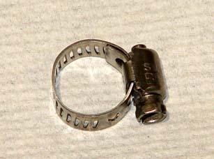
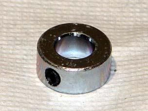
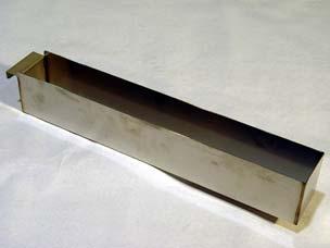
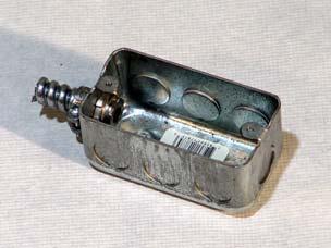
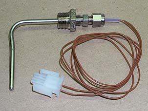
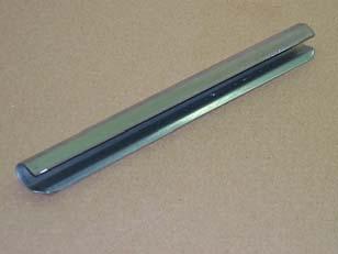
46 Replacement Parts Components Description Component # Figure # Item # ARM ADJUSTABLE STOP /FKM A0101 Figure 16 1 BAFFLE BOX ASSEMBLY AN Figure 16 2 BRACKET, CALROD FKMA258 LZ0006 Figure 16 3 CALROD, 208V 5675W FKM-F C0030 Figure 16 4 CALROD, 240V 5675W FKM-F C0031 Figure 16 5 CASTER, W/TOP PLATE 5" C0406 Figure 16 6 CLAMP, HOSE #6207 #4 HF0009 Figure 16 7 COLLAR, 1/2" SET BRIGHT FT0049 Figure 16 8 CONDENSATION PAN WELDMENT WFKMA341 Figure 16 9 DRAIN PIPE, CONDENSATE FKM FKMA260 Figure FILTER, FKM-F 13.5 X 20.5 FI0007 Figure OUTLET BOX, (ON FKM ONLY FOR POWERING FKF) SB1953 Figure PROBE ASSEMBLY KIT, COMPUTER SB1938 Figure SEMI AUTOMATIC HOSE ASSEMBLY (FKM only) SB1990 Figure SIDE CABINET, L&R FKM/DNF FKMA399 Figure SLIDE, UHMW U-SHAPE.5 X 1/8ID S0106 Figure STRIKER PLATE (DOOR CATCH) FKMA167 Figure SWITCH, ACT. COVER FKMA247 LZ0130 Figure THERMISTER PROBE/FTGS ASSEMBLY SB7656 Figure BRACKET BACK PLATE FKMA259 LZ0007 Figure FILTER BAG CLIP FKM-F ST0015 Figure Figure 16. Components


47 Replacement Parts
48 Wiring Diagrams Wiring Diagrams Figure 17. FKM-F 208V/220V/240 M 46
49 Wiring Diagrams Figure 18. FKM-F 220V/380V, 230V/400V, 240V/415V M 47
50 Wiring Diagrams Figure 19. FKM-FC 208V/220V/240V (Sheet 1 of 4) 48
Extra-Large Electric Pressure Fryer Series. SERIES: FKM Operation Manual
 Extra-Large Electric Pressure Fryer Series SERIES: FKM Operation Manual BKI LIMITED WARRANTY 2812 Grandview Dr. Simpsonville, SC 29680 USA (864) 963-3471 Toll Free: (800) 927-6887 Fax: (864) 963-5316 WHAT
Extra-Large Electric Auto-Lift Fryer. SERIES: BLF Operation Manual
 Extra-Large Electric Auto-Lift Fryer SERIES: BLF Operation Manual BKI LIMITED WARRANTY 2812 Grandview Dr. Simpsonville, SC 29680 USA (864) 963-3471 Toll Free: (800) 927-6887 Fax: (864) 963-5316 WHAT IS
Extra-Large Gas Pressure Fryer Series. SERIES: FKG Operation Manual
 Extra-Large Gas Pressure Fryer Series SERIES: FKG Operation Manual BKI LIMITED WARRANTY 2812 Grandview Dr. Simpsonville, SC 29680 USA (864) 963-3471 Toll Free: (800) 927-6887 Fax: (864) 963-5316 WHAT IS
Gas Pressure Fryer MODELS LGF, LGF-F, & LGF-FC Installation and Operation Manual Serial Numbers and higher
 MODELS LGF, LGF-F, & LGF-FC Installation and Operation Manual Serial Numbers 109576 and higher LIMITED ONE YEAR WARRANTY Warranty Information BKI (The Company ) warrants to the original purchaser/user,
Large All-Purpose Fryer Series. SERIES: DNF Operation Manual
 Large All-Purpose Fryer Series SERIES: DNF Operation Manual BKI LIMITED WARRANTY 2812 Grandview Dr. Simpsonville, SC 29680 USA (864) 963-3471 Toll Free: (800) 927-6887 Fax: (864) 963-5316 WHAT IS COVERED
Fried Food Warmers Series. Series: FW Operation Manual
 Fried Food Warmers Series Series: FW Operation Manual BKI LIMITED WARRANTY 2812 Grandview Dr. Simpsonville, SC 29680 USA (864) 963-3471 Toll Free: (800) 927-6887 Fax: (864) 963-5316 WHAT IS COVERED WHO
Autolift Open Fryer. CR-40F & CR-60F Instruction Manual
 Autolift pen Fryer Instruction Manual 735 Rossiter, St-Jean-sur-Richelieu, Quebec, Canada, J3B 8A4 E-Mail : info@resfab.com Website : www.resfab.com 2007-05 TABLE F CNTENTS Page Limited warranty.. 03 Unpacking..
Operator s Manual. Stripping Solution Applicator
 Operator s Manual Stripping Solution Applicator Record this Important Information Date of Purchase Purchased From Address City State Zip Phone Contact Serial Number Emergency Contacts Medical Emergency
ALTAIR II CONVECTION STEAM COOKER PARTS AND SERVICE MANUAL
 ALTAIR II CONVECTION STEAM COOKER PARTS AND SERVICE MANUAL EFFECTIVE MAY, 0 Superseding All Previous Parts Lists. The Company reserves the right to make substitution in the event that items specified are
OPERATION MANUAL ODS 300 ODS 310
 300 Series Oil Disposal Shuttle OPERATION MANUAL ODS 300 ODS 310 FM07-635J Table of Contents Safety... iii Chapter 1 Introduction...1 1.1 Introduction...1 1.2 Technical Support...1 1.3 Model Configuration
DISCARD DECANTER IF: FAILURE TO COMPLY RISKS INJURY FUNNEL CONTENTS ARE HOT ILLUSTRATED PARTS CATALOG
 ! GMB-PS WARNING Disconnect from power source before removal of any panel or replacement of any component! FUNNEL CONTENTS ARE HOT CAUTION DISCARD DECANTER IF:. CRACKED. SCRATCHED. BOILED DRY. HEATED WHEN
BUNN CWT-CS CWTF-CS BUNN-O-MATIC CORPORATION POST OFFICE BOX 3227 SPRINGFIELD, ILLINOIS PHONE: (217) FAX: (217)
 FAX: (217)") BUNN CWT-CS CWTF-CS ILLUSTRATED PARTS CATALOG Designs, materials, weights, specifications, and dimensions for equipment or replacement parts are subject to change without notice. BUNN-O-MATIC CORPORATION
BUNN CWT-CS CWTF-CS ILLUSTRATED PARTS CATALOG Designs, materials, weights, specifications, and dimensions for equipment or replacement parts are subject to change without notice. BUNN-O-MATIC CORPORATION
DISCARD DECANTER IF: FUNNEL CONTENTS ARE HOT FAILURE TO COMPLY RISKS INJURY
 ! BUNN GMB-PS WARNING Disconnect from power source before removal of any panel or replacement of any component! FUNNEL CONTENTS ARE HOT CAUTION DISCARD DECANTER IF:. CRACKED. SCRATCHED. BOILED DRY. HEATED
DISCONTINUED VERSION Parts listed in this catalog may no longer be available. ILLUSTRATED PARTS CATALOG
 BUNN CWT-CS CWTF-CS DISCONTINUED VERSION Parts listed in this catalog may no longer be available. ILLUSTRATED PARTS CATALOG Designs, materials, weights, specifications, and dimensions for equipment or
Retrofit Instructions for Tower Dryer Moisture Sampler Blower Kit
 Retrofit Instructions for Tower Dryer Moisture Sampler Blower Kit Installation Manual PNEG-1982 Date: 03-26-15 PNEG-1982 2 PNEG-1982 Retrofit Instructions for Tower Dryer Moisture Sampler Blower Kit Table
MODELS CMA-180 VL/180 VLTall PARTS MANUAL Rev 2.02B
 MODELS CMA-180 VL/180 VLTall PARTS MANUAL Rev 2.02B C M A D I S H M A C H I N E S 1 2 7 0 0 K N O T T A V E N U E GARDEN GROVE, CALIFORNIA 92841 800-8 5 4-6 4 1 7 FAX 714-895-2141 www.cmadishmachines.com
Disposal Unit (BKSDU) Burger King Shortening. Operation, Service & Parts Manual BURGER KING BKSDU
 Burger King Shortening. Operation, Service & Parts Manual BURGER KING BKSDU") BURGER KING BKSDU Burger King Shortening Disposal Unit (BKSDU) Operation, Service & Parts Manual Frymaster, a member of the Commercial Food Equipment Service Association, recommends using CFESA Certified
BURGER KING BKSDU Burger King Shortening Disposal Unit (BKSDU) Operation, Service & Parts Manual Frymaster, a member of the Commercial Food Equipment Service Association, recommends using CFESA Certified
Henny Penny Island Warmer Model HMI-103 Model HMI-105 TECHNICAL MANUAL
 Henny Penny Island Warmer Model HMI-103 Model HMI-105 TECHNICAL MANUAL Section TABLE OF CONTENTS Page Section 1. TROUBLESHOOTING... 1-1 1-1. Introduction... 1-1 1-2. Safety... 1-1 1-3. Troubleshooting...
PARTS LIST PL503 WVF-886 VENTLESS FRYER WITH OR WITHOUT ROLL WARMER CONTENTS
 WELLS BLOOMFIELD, LLC 2 ERIK CIRCLE, P. O. Box 280 Verdi, NV 89439 telephone: 775-689-5703 fax: 775-689-5976 www.wellsbloomfield.com 503 PARTS LIST PL503 WVF-886 VENTLESS FRYER WITH OR WITHOUT ROLL WARMER
Henny Penny Island Warmer Model HMI-103 Model HMI-105 TECHNICAL MANUAL
 Henny Penny Island Warmer Model HMI-103 Model HMI-105 TECHNICAL MANUAL THIS PAGE INTENTIONALLY LEFT BLANK. Section TABLE OF CONTENTS Page Section 1. TROUBLESHOOTING... 1-1 1-1. Introduction... 1-1 1-2.
ECOJET EJ-10E & EJ-7E ELECTRIC CONVECTION STEAMER W/TWIN GENERATORS PARTS AND SERVICE MANUAL
 ECOJET EJ-10E & EJ-7E ELECTRIC CONVECTION STEAMER W/TWIN GENERATORS PARTS AND SERVICE MANUAL EFFECTIVE JULY 31, 2014 Superseding All Previous Parts Lists. The Company reserves the right to make substitution
Ventless Hoods For Rotisseries. SERIES: VGH Operation Manual
 Ventless Hoods For Rotisseries SERIES: VGH Operation Manual BKI LIMITED WARRANTY 2812 Grandview Dr. Simpsonville, SC 29680 USA (864) 963-3471 Toll Free: (800) 927-6887 Fax: (864) 963-5316 WHAT IS COVERED
Page 1 of 18. Part# /5/2013
 Part# 1002655-06 8/5/2013 This manual contains important information concerning the installation and operation of the gun washers listed above. Read manual thoroughly and keep for future reference INSTRUCTIONS
MODELS CMA-180 VL/180 VLTall PARTS MANUAL Rev 2.02A
 MODELS CMA-180 VL/180 VLTall PARTS MANUAL Rev 2.02A C M A D I S H M A C H I N E S 1 2 7 0 0 K N O T T A V E N U E GARDEN GROVE, CALIFORNIA 92841 800-8 5 4-6 4 1 7 FAX 714-895-2141 www.cmadishmachines.com
CMA Dishmachines Knott Avenue Garden Grove, CA Undercounter High Temperature Dishwasher. Service Replacement Parts.
 CMA Dishmachines 1700 Knott Avenue Garden Grove, CA 981 Toll Free: 1- (800) 8-617 Fax: 1- (71) 89-11 Service Replacement Parts Undercounter High Temperature Dishwasher Model: UC6e M Machine Serial No.
OPERATING MANUAL/ INSTALLATION
 NHW- 15 HOT WATER MACHINE OPERATING MANUAL/ INSTALLATION 120/240 V 1650/6600 W US 120/240 V 1350/5500 W CAN CONVERTIBLE 2 GA LLON DRIP TRAY INCLUDED ADVANCED TEMPERATURE CONTROL TVT TECHNOLOGY NEWCO ENTEPRISES
Countertop Rotisserie Oven Series. SERIES: DR Operation Manual
 Countertop Rotisserie Oven Series SERIES: DR Operation Manual BKI LIMITED WARRANTY 2812 Grandview Dr. Simpsonville, SC 29680 USA (864) 963-3471 Toll Free: (800) 927-6887 Fax: (864) 963-5316 WHAT IS COVERED
User s Manual and Operating Instructions
 User s Manual and Operating Instructions Model Numbers: PT-18W-DDF-A, PT-20F-DDF-A, PT-20S-DDF, PT-24O-DDF, PT-24-DDF, PT-24-DDF-F, PT-30-DDF, PT-30P-DDF-A, PT-30P-DDF-AF READ AND SAVE THESE INSTRUCTIONS
Crypto-Lock. Model CC-8521B Updated 7/17. Access Control System. MONITEQ, Inc. INSTRUCTION MANUAL
 Crypto-Lock Model CC-8521B Updated 7/17 Access Control System INSTRUCTION MANUAL MONITEQ, Inc. 2 TABLE OF CONTENTS 1. INTRODUCTION..4 2. SPECIFICATIONS.....6 3. SUPPLIED EQUIPMENT.. 6 4. FUNCTIONS OF CONTROLS
BUNN H5E H5M H5X BUNN-O-MATIC CORPORATION POST OFFICE BOX 3227 SPRINGFIELD, ILLINOIS PHONE: (217) FAX: (217)
 FAX: (217)") ! BUNN DISCONNECT FROM POWER SOURCE BEFORE REMOVAL OF ANY PANEL OR REPLACEMENT OF ANY COMPONENT! WARNING H5E H5M H5X WARNING Very Hot Water Use With Care!! ILLUSTRATED PARTS CATALOG Designs, materials,
! BUNN DISCONNECT FROM POWER SOURCE BEFORE REMOVAL OF ANY PANEL OR REPLACEMENT OF ANY COMPONENT! WARNING H5E H5M H5X WARNING Very Hot Water Use With Care!! ILLUSTRATED PARTS CATALOG Designs, materials,
Operator s Manual CAYENNE HEAT N SERVE 4/3 RECTANGULAR RETHERMALIZER ENGLISH
 CAYENNE HEAT N SERVE 4/ RECTANGULAR RETHERMALIZER Item Description Voltage Watts Amps Plug 2050 T4R Countertop without Drain 120 1600 1. 5-15P 2051 TD4R Countertop with Drain 120 1600 1. 5-15P 2 T4R Countertop
Installation and Operation Manual For Electric Fryers. Covering Models SE, SEH, SEM Series
 Installation and Operation Manual For Electric Fryers Covering Models SE, SEH, SEM Series Pitco Frialator, Inc., P.O. Box 501, Jct I-89 & I-93 Concord, NH 03302-0501 509 Route 3A, Bow, NH 03304 (603) 225-6684
TECHNICAL MANUAL TM... Fryer, Deep-Fat, Electric w/solid State Controls 440 Volt, 60 HZ, 3 Phase NSN:
 TM... TECHNICAL MANUAL MODEL USN-50 DESCRIPTION Fryer, Deep-Fat, Electric w/solid State Controls 440 Volt, 60 HZ, 3 Phase NSN: Commercial & Marine Cooking Equipment Gas & Electric Last Updated September
Mobile Hot Food Merchandiser Series. Series: MHB Operation Manual
 Mobile Hot Food Merchandiser Series Series: MHB Operation Manual BKI LIMITED WARRANTY Grandview Drive Simpsonville, SC 0 USA () - Toll Free: (00) - Fax: () - WHAT IS COVERED WHO IS COVERED COVERAGE PERIOD
Xaact Spot. Xaact Hot Spot
 Xaact Spot & Xaact Hot Spot INFORMATION & OPERATING INSTRUCTIONS READ AND UNDERSTAND THESE INSTRUCTIONS BEFORE OPERATING THE MACHINE 78-00012 Rev. 101211 1 CONTENTS: Machine Specifications............
Operating Instructions for the BBO-1 and BBO-2 Basket Blasters
 Operating Instructions for the BBO-1 and BBO-2 Basket Blasters 2101 West Cabot Boulevard Langhorne, PA 19047-1893 www.empire-airblast.com Page 2 Model Number: Serial Number: Date of Purchase: Date of Installation:
BUNN A10 & A10-A BUNN-O-MATIC CORPORATION POST OFFICE BOX 3227 SPRINGFIELD, ILLINOIS PHONE: (217) FAX: (217)
 FAX: (217)") BUNN A0 & A0-A ILLUSTRATED PARTS CATALOG Designs, materials, weights, specifications, and dimensions for equipment or replacement parts are subject to change without notice. BUNN-O-MATIC CORPORATION POST
BUNN A0 & A0-A ILLUSTRATED PARTS CATALOG Designs, materials, weights, specifications, and dimensions for equipment or replacement parts are subject to change without notice. BUNN-O-MATIC CORPORATION POST
DIGITAL CAP THE MAXX PRESS OPERATOR S MANUAL
 DIGITAL CAP OPERATOR S MANUAL HOTRONIX Safety Instructions When using your heat press, basic precautions should always be followed, including the following: 1. Read all instructions. 2. Use heat press
6 oz. Kettle Poppers With / Love My Popper Kettle Popcorn Machine Instruction Manual Models: 1871,2660,2661
 Part No. 49217 Revised: June 2004 With / Love My Popper Kettle Popcorn Machine Instruction Manual Models: 1871,2660,2661 Cincinnati, OH 45241-4807 USA SAFETY PRECAUTIONS 2 Models: 1871,2660,2661 INSTALLATION
Model: FT110 Dishwasher
 PARTS MANUAL HOBART FOOD EQUIPMENT CO., LTD Model: FT110 Dishwasher HOBART FOOD EQUIPMENT CO., LTD 2003-07-10 Table of Contents Page Description 2 Panels, Upper chamber and Tank 4 Control Box 6 Control
P-60 and 60 Special. Popcorn Machine Instruction Manual Model #1866, #2085, #2086 and #2656. Cincinnati, OH USA
 Part No. 49064 Revised: March 2004 P-60 and 60 Special Popcorn Machine Instruction Manual Model #1866, #2085, #2086 and #2656 Models #1866 and #2086 Models #2085 and #2656 Cincinnati, OH 45241-4807 USA
MC MC MC MC MC833130
 Pic-A-Vac Model: MC832085 MC833085 MC832105 MC833105 MC832130 MC833130 OPERATION SERVICE PARTS CARE Revised 8/01 FOR COMMERCIAL USE ONLY IMPORTANT SAFETY INSTRUCTIONS When using an electrical appliance,
OPERATIONS MAINTENANCE MANUAL
 OPERATIONS MAINTENANCE MANUAL COOK & HOLD OVEN SYSTEMS WITTCO MODEL NUMBERS 1300-AD-SS 1300-AD-SS-SPLIT LIMITED WARRANTY Wittco warrants the Products that it manufactures to be free from defects in materials
ILLUSTRATED PARTS LIST ENDURO VALVE
 ILLUSTRATED PARTS LIST ENDURO 175 8 VALVE Publication Number: 620917901IPL Revision Date: October 10, 2011 Revision: G Visit the IMI Cornelius web site at www.cornelius.com for all your Literature needs.
 WARNING!! The attached Gold Medal Manual is for reference only and is not intended for any other purpose. The information contained in these on line manuals is subject to change at any time. Improvements
Instruction Manual. Cheddar Easy All-In-One Cheese Corn Shop
 Instruction Manual Cheddar Easy All-In-One Cheese Corn Shop Model No. 2703-00-000 10700 Medallion Drive, Cincinnati, Ohio 45241-4807 USA 2017 Gold Medal Products Co. Part No. 110028 SAFETY PRECAUTIONS
Model: PS-2 ProSense II Item # OPERATION SERVICE PARTS CARE
 Model: PS-2 ProSense II Item # 49001 OPERATION SERVICE PARTS CARE FOR COMMERCIAL USE ONLY IMPORTANT SAFETY INSTRUCTIONS When using an electrical appliance, basic precautions should always be followed,
model NO. LSS GALLON SKID MOUNTED HIGH PRESSURE SPRAYER ASSEMBLY / OPERATION INSTRUCTIONS / PARTS
 000 model NO. LSS- 00 GALLON SKID MOUNTED HIGH PRESSURE SPRAYER ASSEMBLY / OPERATION INSTRUCTIONS / PARTS Part number and descriptions can be obtained from the illustrated parts list section of this manual.
User s Manual and Operating Instructions
 User s Manual and Operating Instructions Model Numbers: CL-30P-DDF, CL-20F-DDF, CL-24O-DDF, CL-30-DDF READ AND SAVE THESE INSTRUCTIONS IMPORTANT: Read and understand all of the directions in this manual
Smart IR Sensor. Installation and Operation Manual PNEG Date: PNEG-1640
 Smart IR Sensor Installation and Operation Manual PNEG-1640 Date: 12-21-11 PNEG-1640 2 PNEG-1640 Smart IR Sensor Table of Contents Contents Chapter 1 Safety...4 Safety Guidelines...4 Chapter 2 Application...6
Henny Penny Open Fryer Electric Model OE-100
 Henny Penny Open Fryer Electric Model OE-100 OPERATOR MANUAL Henny Penny Model OE-100 LIMITED WARRANTY FOR HENNY PENNY APPLIANCES Subject to the following conditions, Henny Penny Corporation makes the
Parts and Service Manual
 Section II Parts and Service Manual (70241A) CLARKE TECHNOLOGY Operator's Manual - MINI MAX Page -29- Frame and Front Cover Assembly Drawing 2/01 Page -30- CLARKE TECHNOLOGY Operator's Manual -MINI MAX
TECHNICAL ASSISTANCE TOLL FREE TELEPHONE NUMBER TECHNICAL ASSISTANCE FAX:
 ACORN SAFETY P.O. BOX 3527 CITY OF INDUSTRY, CA 91744-0527 UNITED STATES OF AMERICA WWW.ACORNSAFETY.COM INSTALLATION, OPERATION AND MAINTENANCE INSTRUCTIONS ELECTRIC ALARM WITH LIGHT AND HORN Model: S0000-AL2-C1D1-DB1
Filtration. General Instructions
 Filtration General Instructions Ultrafryer Systems 302 Spencer Lane P.O. Box 5369 San Antonio, TX 78201 Local: (210) 731-5000 Toll-Free: (800) 525-8130 Fax: (210) 731-5099 Web: www.ultrafryer.com 30A181-Jul2007
EFFECTIVE: MAY, American Dish Service ADS MODEL: ASQ GLASSWASHER PARTS MANUAL. 900 Blake Street Edwardsville, Kansas (913) /08
 /08") EFFECTIVE: MAY, 2014 American Dish Service ADS MODEL: ASQ GLASSWASHER PARTS MANUAL 900 Blake Street Edwardsville, Kansas 66111 (913)422-3700 05/08 The American Dish Service part numbers contained in this
EFFECTIVE: MAY, 2014 American Dish Service ADS MODEL: ASQ GLASSWASHER PARTS MANUAL 900 Blake Street Edwardsville, Kansas 66111 (913)422-3700 05/08 The American Dish Service part numbers contained in this
PARTS MANUAL. American Dish Service MODEL: 5-AG-S ADS LOW TEMPERATURE DISHWASHER EFFECTIVE: JULY, 2013 C 4/08
 EFFECTIVE: JULY, 2013 ADS LOW TEMPERATURE DISHWASHER MODEL: PARTS MANUAL 900 Blake Street Edwardsville, Kansas 66111 (913)422-3700 C 4/08 The American Dish Service part numbers contained in this publication
WET/DRY VACUUMS PV-12 PV-18 PV-18S PV-18D. Gulper 12P Gulper 18P Gulper 18PS Gulper 18PD OPERATING & MAINTENANCE
 WET/DRY VACUUMS PV-12 PV-18 PV-18S PV-18D Gulper 12P Gulper 18P Gulper 18PS Gulper 18PD INTRODUCTION OPERATING & MAINTENANCE INSTRUCTIONS This operator s book has important information for the use and
AURA WIDE AREA VACUUM Parts Manual
 AURA WIDE AREA VACUUM Parts Manual INTRODUCTION OPERATING & MAINTENANCE INSTRUCTIONS READ THIS BOOK This operator s book has important information for the use and safe operation of this machine. Read this
MRS-6 Maxi-Guard II. Model: C , 12, 13, 14 OPERATION SERVICE PARTS CARE. Revised 2/02
 MRS-6 Maxi-Guard II Model: C86006-11, 12, 13, 14 OPERATION SERVICE PARTS CARE Revised 2/02 OPERATING INSTRUCTIONS INSPECTION Carefully unpack and inspect your machine for shipping damage. Each unit is
CRV Clean Room Vacuum
 CRV Clean Room Vacuum Model: C80704-01, 02 SS (115V) C80704-03, 04 Painted (115V) C80704-07, 12 Painted (240V) C80704-08, 09 SS (240V) OPERATION SERVICE PARTS CARE Revised 7/02 FOR COMMERCIAL USE ONLY
Service Parts, Kits and Accessories
 The parts identification guides on the following pages have been designed to give a quick reference to component parts used on pilot ignition agricultural building heaters. The guides identify components
RINGMASTER 5-1/2 & 7 COTTON CANDY MACHINE
 3243 North California Avenue, Chicago, IL 60618 RINGMASTER 5-1/2 & 7 COTTON CANDY MACHINE 120 Volt, Single Phase, 50/60 Cycle 230 Volt, Single Phase, 50 Cycle READ and UNDERSTAND these operating, servicing,
Model PF 2030 Wide Area Vacuum Cleaner
 Model PF 2030 Wide Area Vacuum Cleaner OPERATING INSTRUCTIONS COMMERCIAL WIDE AREA SWEEPER VACUUM CONGRATULATIONS YOU HAVE JUST ACQUIRED A HIGH QUALITY VACUUM CLEANER. PLEASE READ THIS MANUAL CAREFULLY,
WAV-26 UPRIGHT WIDE AREA VACUUM
 PARTS & OPERATING MANUAL WAV-26 UPRIGHT WIDE AREA VACUUM PLEASE READ THIS BOOK This operator s book has important information for the use and safe operation of this machine. Read this book carefully before
MERCURY HD-22 AUTOSCRUBBER Safe Operations
 Safe Operations PROPER OPERATING PROCEDURES By following proper operating procedures, the Mercury DS- 26 Autoscubber can provide you with productive, easy to operate, safe and clean floors. This machine
UNIVERSAL 750 PRE-MIX DISPENSER
 Anoka, MN. 0 - Telephone -00--00 Facsimile -00--0 MODEL NO. xxx xxx Universal 0 of Control Code A Manual Part No. 00 -- Revised: -- ªIMI Cornelius Co., - Anoka, MN. 0 - Telephone -00--00 Facsimile -00--0
PACER 30 VACUUM IMPORTANT SAFETY INSTRUCTIONS READ AND UNDERSTAND ALL INSTRUCTIONS BEFORE OPERATING OR SERVICING MACHINE
 DANGER! PACER 30 VACUUM IMPORTANT SAFETY INSTRUCTIONS READ AND UNDERSTAND ALL INSTRUCTIONS BEFORE OPERATING OR SERVICING MACHINE Failure to Observe These Instructions Can Cause Fire, Electrical Burn, Shock
DFG-100 XCEL SERIES GAS CONVECTION OVEN REPLACEMENT PARTS LIST
 DFG-00 XCEL SERIES GAS CONVECTION OVEN REPLACEMENT PARTS LIST EFFECTIVE MARCH 00 BLODGETT OVEN COMPANY, Lakeside Avenue, Burlington, Vermont 00 USA Telephone: (0) 0-00 (00) - Fax: (0) 0- www.blodgett.com
EX20. Parts List Models: (100C) (cold), (100H) (heated), (100SC) (single cord, heated) Form No /2015 REV A
 (cold), (100H) (heated), (100SC) (single cord, heated) Form No /2015 REV A") EX0 Parts List Models: 560588 (00C) (cold), 560589 (00H) (heated), 560590 (00SC) (single cord, heated) Form No. 56065 5/05 REV A GENERAL VIEW Item Ref. No. Qty Description Base System Recovery System Solution
EX0 Parts List Models: 560588 (00C) (cold), 560589 (00H) (heated), 560590 (00SC) (single cord, heated) Form No. 56065 5/05 REV A GENERAL VIEW Item Ref. No. Qty Description Base System Recovery System Solution
Lifetime Limited Warranty
 Hampton Bay Lifetime Limited Warranty The retailer warrants the fan motor to be free from defects in workmanship and material present at time of shipment from the factory for a lifetime after the date
IMPORTANT SAFEGUARDS
 IMPORTANT SAFEGUARDS Definitions Whenever used, the following symbol and terms identify safety and property damage messages and designate a level of hazard seriousness. - This is the safety alert symbol.
6 Oz. Twin Pop. Popcorn Machine Instruction Manual Model #2666EX. Cincinnati, OH USA. Part No EX Revised June 1996
 Popcorn Machine Instruction Manual Model #2666EX Part No. 16169EX Revised June 1996 Cincinnati, OH 45214-2089 USA SAFETY PRECAUTIONS This equipment is designed and sold for commercial use only. This equipment
OCH-SS series Direct Wired Units Indoor * and Outdoor Comfort Heaters
 1200 North Main Street Fostoria, OH 44830 Phone: 800-495-4525 Fax: 419-435-0842 A DIVISION OF www.fostoriaindustries.com OCH-SS series Direct Wired Units Indoor * and Outdoor Comfort Heaters *EXCLUDING
TURBO Fiberglass Cone Fan and Grill Fan 48'' Belt Drive. Installation & Operator s Instruction Manual
 TURBO Fiberglass Cone Fan and Grill Fan 48'' Belt Drive Installation & Operator s Instruction Manual July 1998 MV1383B Chore-Time TURBO TM Fan Extended Warranty Chore-Time Equipment warrants new TURBO
WAV-30 WIDE AREA VACUUM
 PARTS & OPERATING MANUAL WAV-30 WIDE AREA VACUUM PLEASE READ THIS BOOK This operator s book has important information for the use and safe operation of this machine. Read this book carefully before starting
DISCARD DECANTER CAUTION . CRACKED . BOILED DRY. HEATED WHEN EMPTY. USED ON HIGH FLAME FAILURE TO COMPLY RISKS INJURY FUNNEL CONTENTS ARE HOT PN: 658
 PN: 658 IF: PN: 658! IF: PN: 658! IF: BUNN C, CT & CTF! CAUTION WARMERS AND SURFACES ARE HOT C SERIES READY CAUTION DISCARD DECANTER. CRACKED. SCRATCHED. BOILED DRY. HEATED WHEN EMPTY. USED ON HIGH FLAME.
DFG-100 XCEL SERIES GAS CONVECTION OVEN REPLACEMENT PARTS LIST
 DFG-00 XCEL SERIES GAS CONVECTION OVEN REPLACEMENT PARTS LIST EFFECTIVE JANUARY, 0 Superseding All Previous Parts Lists. The Company reserves the right to make substitution in the event that items specified
OWNER'S MANUAL IMPORTANT: READ OWNER'S MANUAL CAREFULLY MODEL : CHEETAH DC2000 FOR YOUR CONVENIENCE, RECORD THE FOLLOWING IMPORTANT INFORMATION MODEL:
 OWNER'S MANUAL IMPORTANT: READ OWNER'S MANUAL CAREFULLY MODEL : CHEETAH DC2000 FOR YOUR CONVENIENCE, RECORD THE FOLLOWING IMPORTANT INFORMATION MODEL: SERIAL NUMBER:-------- DATE PURCHASED: PURCHASED FROM:
Products documentation (REVISION DATE: 03/10/2011) OMFP6010 (60cm PIROLITIC OVEN)
 OMFP6010 (60cm PIROLITIC OVEN)") Products documentation (REVISION DATE: 03/10/2011) OMFP6010 (60cm PIROLITIC OVEN) Ovens Service Manual Models OMFP6010 CONTENTS This document has been published to be used for service only. The contents
Products documentation (REVISION DATE: 03/10/2011) OMFP6010 (60cm PIROLITIC OVEN) Ovens Service Manual Models OMFP6010 CONTENTS This document has been published to be used for service only. The contents
SINGLE BUNN-O-MATIC CORPORATION POST OFFICE BOX 3227 SPRINGFIELD, ILLINOIS PHONE: (217) FAX: (217)
 FAX: (217)") ! SINGLE WARNING DISCONNECT FROM POWER SOURCE BEFORE REMOVAL OF ANY PANEL OR REPLACEMENT OF ANY COMPONENT! PRIOR TO S/N SNG000000 gal gal gal START ON / WARMER SELECTOR READY! BUNN MANUFACTURED BY BUNN-O-MATIC
! SINGLE WARNING DISCONNECT FROM POWER SOURCE BEFORE REMOVAL OF ANY PANEL OR REPLACEMENT OF ANY COMPONENT! PRIOR TO S/N SNG000000 gal gal gal START ON / WARMER SELECTOR READY! BUNN MANUFACTURED BY BUNN-O-MATIC
Fountain Classic. Installation and Owner s Manual. Page 16
 Fountain Classic Installation and Owner s Manual Page 16 4120 NW 44th St Lincoln, NE 68524 USA Tel: 402.467.9300 Toll Free in the USA: 800.875.5915 Fax: 402.467.9393 www.purewaterinc.com Page 2 Fountain
690 and Power Fishing Systems
 INSTRUCTION MANUAL 690 and 690-22 Power Fishing Systems Includes Serial Number AAR 3800 and higher (120 volt model) Includes Serial Number AAT 00500 and higher (220 volt model) Read and understand all
CATALOG OF REPLACEMENT PARTS HSROG SERIES SINGLE RACK OVEN. A product of HOBART CORPORATION 701 S. RIDGE AVENUE TROY, OHIO
 CATALOG OF REPLACEMENT PARTS HSROG SERIES SINGLE RACK OVEN HSROG ML-111148 A product of HOBART CORPORATION 701 S. RIDGE AVENUE TROY, OHIO 45374-0001 FORM 43003 (June 2001) HOT SECTION 26 OVEN TOP SECTION
STAND ALONE DRYER BASE. Parts Manual
 STAND ALONE DRYER BASE Parts Manual TABLE OF CONTENTS DRYER BASE SYSTEM DRYER BASE SYSTEM ASSEMBLY (FIG. 1) 3 FRAME ASSEMBLY (FIG. 2). 5 CONVEYOR DRIVE ASSEMBLY (FIG. 3)...7 IDLER SHAFT / TENSIONER ASSEMBLY
Dirt Dragon. Operator and Parts Manual WOOD FLOOR CLEANING MACHINE
 Dirt Dragon WOOD FLOOR CLEANING MACHINE Operator and Parts Manual 1001 Brown Avenue Toledo, Ohio 43607-0127 Customer Service: 800-441-1934 Fax: 800-942-2007 Technical Service: 877-856-5954 www.basicoatings.com
MK-1080 PAVER SAW OWNER S MANUAL & PARTS MANUAL
 www.mkdiamond.com OWNER S MANUAL & PARTS MANUAL Revision 106 03.2019 Manual Part No. 166894 Caution: Read all safety and operating instructions before using this equipment. This manual MUST accompany the
LARGE AREA VACUUM LAV-30
 LARGE AREA VACUUM LAV-30 INTRODUCTION OPERATING & MAINTENANCE INSTRUCTIONS READ THIS BOOK This operator s book has important information for the use and safe operation of this machine. Read this book carefully
Instruction Manual. Super 88
 Instruction Manual Super 88 10700 Medallion Drive, Cincinnati, Ohio 45241-4807 USA Part No. 49555 SAFETY PRECAUTIONS DANGER Machine must be properly grounded to prevent electrical shock to personnel. Failure
MTC-Series Manual Trash Compactors Instruction Manual
 Vestil Manufacturing Co. 2999 North Wayne Street, P.O. Box 507, Angola, IN 46703 Telephone: (260) 665-7586 -or- Toll Free (800) 348-0868 Fax: (260) 665-1339 Website: www.vestilmfg.com e-mail: info@vestil.com
COS-101 NON SELF FLUSHING COMBI REPLACEMENT PARTS LIST
 COS-101 NON SELF FLUSHING COMBI REPLACEMENT PARTS LIST EFFECTIVE FEBRUARY 16, 2012 Superseding All Previous Parts Lists. The Company reserves the right to make substitution in the event that items specified
LOKPRINT. Industrial Apparel Label Station. Operation / Maintenance And Parts List. Users Manual AVERY DENNISON. Manual Edition 5.0.
 Users Manual LOKPRINT Industrial Apparel Label Station Operation / Maintenance And Parts List AVERY DENNISON Manual Edition 5.0 09 June 2010 Manual Part Number 221398 This page intentionally left blank
TECHNICAL ASSISTANCE TOLL FREE TELEPHONE NUMBER TECHNICAL ASSISTANCE FAX:
 ACORN SAFETY P.O. BOX 3527 CITY OF INDUSTRY, CA 91744-0527 UNITED STATES OF AMERICA WWW.ACORNSAFETY.COM INSTALLATION, OPERATION AND MAINTENANCE INSTRUCTIONS ELECTRIC ALARM WITH LIGHT AND HORN Models S0000-AL1
Popcorn Machine Instruction Manual Model #2551EX
 Part No. 49793EX Revised January 2004 Popcorn Machine Instruction Manual Model #2551EX Cincinnati, OH 45214-2089 USA. SAFETY PRECAUTIONS INSTALLATION INSTRUCTIONS SETUP Remove all packing material and
Parts Lists with Exploded Views
 Parts Lists with Exploded Views Strip, Filler (Island Trim) 0 Hinge, Door Stiffener Support Assy LH Trim, Center Post, 0" Panel, Door 0 W/O Logo *Special Order, Call Factory Parts Department Door, Oven
USER GUIDE DEEP FRYER WITH OIL FILTRATION SYSTEM
 USER GUIDE DEEP FRYER WITH OIL FILTRATION SYSTEM Emeril is a trademark of Martha Stewart Living Omnimedia, Inc. Copyright 2017, Martha Stewart Living Omnimedia, Inc. All rights reserved. Important Safeguards
Instruction Manual. Astro Staging Cabinet
 Instruction Manual Astro Staging Cabinet 10700 Medallion Drive, Cincinnati, Ohio 45241-4807 USA 2017 Gold Medal Products Co. Part No. 40269 SAFETY PRECAUTIONS DANGER Machine must be properly grounded to
ICE/BEVERAGE DISPENSER
 Illustrated Parts List ICE/BEVERAGE DISPENSER Model: Enduro-2XX intellicarb Publication Number: 6209956IPL Revision Date: August 3, 200 Release Date: March 26, 204 Revision: B Visit the Cornelius web site
Getz Equipment Innovators 450 lb Dual Portable Dry Chemical Fill System
 Getz Equipment Innovators 450 lb Dual Portable Dry Chemical Fill System 1 Revised 11/18/10 2320 Lakecrest Drive, Pekin IL 61554 PH. (888) 747-4389 Fax (309) 495-0625 Website: www.getzequipment.com LIMITED
(3 plastic wire connectors,blade balancing kit, 2 extra mounting screws #10-32 for outlet box.)
") Excel Lighting & Manufacturing Ltd. Lifetime Limited Warranty Excel Lighting & Manufacturing Ltd. Warrants the fan motor to be free from defects in workmanship and material present at time of shipment
Excel Lighting & Manufacturing Ltd. Lifetime Limited Warranty Excel Lighting & Manufacturing Ltd. Warrants the fan motor to be free from defects in workmanship and material present at time of shipment
Electric Automatic Carpet Extractor. Operator and Parts Manual. Model No.: Rev. 00 (11-99)
") 1520 Electric Automatic Carpet Extractor Model No.: 607649 Operator and Parts Manual TENNANT COMPANY Commercial Products 12875 RANSOM STREET HOLLAND MI 49424 U.S.A. FAX: 1 800 678 4240 CUSTOMER SERVICE:
1520 Electric Automatic Carpet Extractor Model No.: 607649 Operator and Parts Manual TENNANT COMPANY Commercial Products 12875 RANSOM STREET HOLLAND MI 49424 U.S.A. FAX: 1 800 678 4240 CUSTOMER SERVICE: