SLV CONTROLLER 105N46XX SERIES
|
|
|
- Gervase Griffin
- 5 years ago
- Views:
Transcription

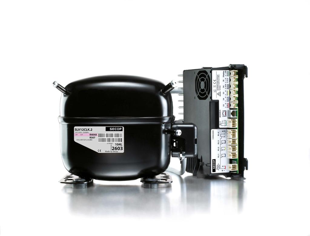
1 WITH MORE THAN 50 YEARS OF EXPERIENCE IN COMPRESSOR TECHNOLOGY AND HIGHLY COMMITTED EMPLOYEES, OUR FOCUS IS TO DEVELOP AND APPLY THE ADVANCED COMPRESSOR TECHNOLOGIES TO ACHIEVE STANDARD SETTING PERFORMANCE FOR LEADING PRODUCTS AND BUSINESSES AROUND THE WORLD. SLV CONTROLLER 105N46XX SERIES OPERATING INSTRUCTIONS TOOL 4 COOL Flexible control settings SETTING THE STANDARD
2 2
3 3
4 TABLE OF CONTENTS 1. Introduction Applications Capabilities Operating Conditions Programming Interface Hardware Interface Description Functions Installation Checklist Connect Cables General Wiring Modbus RTU Mains / Earthing / Compressors General System Design Hints User Interfaces CRA 172 Operations Operating using TOOL4COOL Operation using ADAP-KOOL Operating using Third Party Software Description of Functions Application Selector Modbus Addressing Temperature Acquisition Temperature Logger Temperature Alarms Reference for the Capacity Controller Compressor Capacity Control Safety Function Emergency Cooling Function Defrost Control Function Melt Function Case Cleaning Function Condenser or Compressor Compartment Fan Control Evaporator Can Control Blind Control Function Light Control Function Real Time Clock and Control Timer Alarm Handler Event Logging System Service Mode Local Indications and Menu Structure of Relays of low Voltage I/O Storing and Restoring to Factory Settings Parameters Modbus Technical Data SLV15CNK.2 Compressor R SLV12CLK.2 Compressor R404A/R SLV 105N46xx Series Controller Dimensions Ordering... 98
5 1. INTRODUCTION 1.1 Applications The SLV General Purpose controller 105N46xx regulates temperatures in refrigeration appliances, including supermarket refrigeration, freezer cabinet systems and industrial kitchens. 1.2 Capabilities The controller is fully functional in every operation required for modern refrigeration control. The controller connects to a range of interfaces such as potentiometers, LED displays, PC software and bus monitoring systems. The controller features an internal temperature and event logging system and general purpose interface for broad and flexible application. 1.3 Operating Conditions The compressor should be operated under the following conditions: Line voltage: 230 V AC 50 Hz Ambient temperature: 0 to 43 C The controller should not be used in ambient air containing acid or alkaline. To ensure an optimal service life, the ambient temperature should be kept as low as possible (ambient temperature range for operation: 0 to 38 C compartment temperature, humidity 30 90%). The ventilation holes on the control units should not be covered and no objects should be lent up against the enclosure. The control system should not come into contact with dust or water. Ambient temperature range for storage: - 20 C to 70 C 1.4 Programming Interface The controller can be accessed via: The local display CRA 172 The Secop PC Service tool TOOL4COOL together with a Bluetooth gateway The Danfoss software tool, ADAP KOOL via Modbus A custom interface - please contact Secop for further information regarding custom interfaces. 5
6 1.5 Hardware Interface Description Supply These are the supply lines. The L and N supply terminals must be from the main supply. The E must be connected to protective earth. Please refer to the hardware specifications for the approved operating conditions. Relay section There are 5 relays which can be used for several purposes; they can be configured by the software parameters. The R1, R2, R3 and R4 are active outputs that direct the supply voltages to the output terminals. The R5 is galvanic separated and can be used for either switching external supply voltage or switching external auxiliary signals. Please refer to the hardware specifications for approved operating conditions. Modbus This galvanic insulated terminal is used to connect a bus system according to the Modbus standard. Please refer to the hardware specifications for approved operating conditions. Sensors There are up to 5 temperature sensor inputs available. The use of the sensor can be configured by the software parameters. Generally the S3 and S4 sensors are used to measure the product s temperature, S5 for controlling defrost, S3b for auxiliary functions and S6 for the temperature logger system. Please refer to the hardware specifications and accessory listings for specification, approved operating conditions and sensors. Digital Input DI The digital input can be used to connect the auxiliary contact device, external for the door sensor and light switch. The controlling function can be selected by the software parameters. Please refer to the hardware specifications for approved operating conditions. The display connection is used to connect the Secop display CRA 172. Please refer to the hardware specifications for approved operating conditions. Safety hints: Sensors, DI and connectors are not insulated. Each appliance needs an insulation which is acceptable for 230 V environment. The compressor application must factor in power supply from an electrical circuit with the appropriate fuse or circuit breaker. In addition, the use of a GFCI (Ground Fault Circuit Interrupter) or RCD (Residual Current Device) is recommended. 6
7 1.6 Functions The main functions of the SLV compressor are: Motor control for the energy-optimised variable speed brushless DC motor used in the Secop SLV compressor Management of minimum and maximum run times Condenser and compressor fan control Temperature measurement and algorithms for determining the temperatures in the cooling application PI control to determine the required cooling capacity control (optional) Control menus to change the operating status or set parameters Alarm system reporting faults on the display, with a buzzer, via the Modbus interface, or via the alarm relay Data logging system to store events in the memory of the control unit. Data logs can be read via the system bus Hot gas defrost system Cold storage fan control module Modbus communication for supermarket monitoring systems The controller also features integrated monitoring of the operating conditions and takes corrective action to prevent any damage to the electronics, which may occur in the event of an overload. The following monitoring functions ensure that operating conditions remain within the acceptable range: Temperature sensor on the printed circuit boards to monitor the temperature of the electronics in the enclosure. Temperature sensor to monitor temperature in the motor inverter. Monitoring for correct motor speed; motor speeds outside the permissible range can damage the valves and bearings. Inadequate line voltage due to fluctuations in the line supply. Locked rotor caused by excessive pressure. Other advantages: Minimal start current required due to non-simultaneous compressor and fan start up schedules. Controlled restart. Control of the pressure equalization time. 7


")
 Secop Bluetooth")

8 2. INSTALLATION Installation involves the following steps: Checklist Connect cables Install gateway driver Set Modbus address in controller Software installation and configuration 2.1 Checklist Check that you have the following before starting installation: Secop SLV 105N46xx series controller Tool4Cool LabEdition software installation CD Service Product key for SLV controller - on request - NTC temperature sensors (colour-coded) CRA 172 (cable must be ordered separately) Secop Bluetooth gateway with USB power supply Gateway USB power supply DSUB-9 / RJ45 adaptor RJ45 Ethernet patch cable (not available from Secop) 8
9 2.2 Connect Cables The maximum cable length should not exceed 3 metres for all internal and external applications. A cable length of more than 3m could alter the EMI performance. In this case, the customer must make application specific inquiries to determine requirements for the certification of cooling applications. Under normal circumstances the supply line and the communication lines are longer; it is recommended to follow the installation guideline for the Modbus. All protective earth lines, PE, in the application must be collected to one star point. This prevents loop currents which could cause problems concerning the electronic components, communication lines and sensors. The star-point is normally a screwed terminal on the chassis. The compressor must be connected directly to PE; due to the low voltage decree. The PE connection by the motor cable shield has a more functional cause and is not sufficient as a safety relevant connection, so in case of an error it is not able to carry the whole current. The cable shield of the motor cable must have a low impedance connection to the compressor. The connection should be made to the compressor where the shield has a large surface area. The newer compressors will come with a clamp instead of a plug for the shield. Signal and data lines can be put together but divided from the 230 Vac power lines, including those lines which are switched by the internal relays. The relay switched lines may be put together with the supply line as long as the other lines are not carrying current disturbances. The preferred way of installation heavily relies on the switched loads. In case of doubt the lines should be installed separately; to avoid coupling of disturbance between the lines. Connecting the Modbus communication line between two devices when the cable is installed outside the building or between two buildings is not allowed. This prevents potential induction problems, in case of lightning. 2.3 General Wiring 9
10 2.4 The controller has a connection port for a CRA 172 display for local operation and temperature readouts. Furthermore it s possible to use the display for alarm indication, depending on whether the function is enabled. As well as the 3½ digit LED display, the CRA 172 also has 3 buttons. 2.5 Modbus RTU The bus can be connected to a bus monitoring system based on the Modbus specification for RS-485 based interfaces. The bus connection can be used for remote monitoring of the cabinet or for local service by means of the Tool4Cool service tool. For further information, please refer to section 6, Modbus 2.6 Mains / Earthing / Compressor 10
11 2.7 General System Design Hints Airflow Operating conditions Storage conditions 3 m/s -10 C to 43 C - humidity < 90 % rh non condensing -20 C to 70 C - humidity < 90 % rh non condensing Supply voltage 230 V (+15 % / - 20 %) Frequency 50/60 Hz Input power rating max 1000 W at 230 V (+15 % / - 20 %) 11

12 3. USER INTERFACES 3.1 CRA 172 Operations The different parameters of the SLV controller can be accessed via the local display or via the Modbus. In this section, only the local display interface will be described. The display CRA 172 performs the following functions: Daily operation of the cooling appliance, readout of measurements and status of the refrigeration system, actual temperature, alarms, defrost activation, stop mode, setting of parameters, reset of alarms and more. By entering the correct access code, it s also possible to get into the service level of the controller. Besides the numeric display, there are 4 additional LED s which show the status of Alarm, Defrosting, Service and Cooling. To access the different parameters of the SLV controller for the local display interface, there are three different access levels. Each level can be protected with an individual access code, defined by the manufacturer of the cooling appliance. If a level is protected with an access code, this code must be entered first. If the SLV controller is accessed via both the CRA 172 and the Modbus at the same time, the latest modified value for a setting will be stored as the final. 3.2 Operating using TOOL4COOL The controller can be programmed and optimized via the Bluetooth gateway from a PC using the Tool4Cool software. An example of the Tool4Cool user interface showing the main parameter groups of the SLV compressor is shown below. For details please look into the separate documentation Example: 3.3 Operation using ADAP-KOOL The Danfoss ADAP-KOOL software is used to control supermarket refrigeration systems. Please refer to existing documentation for operating instructions and further information. The literature number (in brackets) might change according to version and language: Data communication between ADAP-KOOL refrigeration controls Installation guide (RC8AC602) Service Tool AK-ST 500 Software for operation of AK controllers Manual (RS8ES402) ADAP-KOOL Refrigeration control systems Catalogue (RK0YG402) 3.4 Operating using Third Party Software The SLV controller can also be accessed from a third party front end. For details please contact lightcommercial@secop.com and refer to separate documentation available from Secop. 12
13 4. DESCRIPTION OF FUNCTIONS 4.1 Application selector Purpose Many light commercial cooling applications are supposed to cool a variety of goods. The cooling of different types of goods requires specific temperature settings and functions of defrosting, fan control etc. These settings are considered to be application dependent. The selection of the application can be done by the end user, timer based or pre defined from the factory Functional description Using the application selector, it is possible to select up to five different sets of settings which provide the SLV controller with different functions or simply different temperature settings. The selection of the actual application can be done by the daily user via the local operation display, the internal control timer, digital input or as a factory selection at the OEM. In the parameter overview the default settings for all parameters are shown for each of the five possible applications. Furthermore, the overview indicates whether a setting can be set differently for each of the five applications or if this setting is one common setting for all applications. If different settings are possible in the particular applications, this is indicated with an x in the column Multi apps Before an application can be selected, this application must be enabled. Application selection by the daily user: If more than one application is enabled, the daily user can select one of the enabled applications by pressing the middle button on the display. If more than two applications are enabled, repeatedly pressing the middle button switches between the applications. If the digital input DI1 is configured for application change over, the predefined application will be selected, as soon as the DI1 is closed. As soon as the DI1 is disconnected, the selection of application depends on the remaining settings. If automatic application change over is desired, this can be achieved by using the control timer to select another application during the active timer. As an alternative, it is possible to force each application into another application, as long as the controller is in night mode Restrictions For all the settings which can be programmed differently in the five applications, this is only made possible if the application has first been selected. This means that each application has to be programmed separately, by enabling and selecting the application prior to the programming Dependencies None 13
14 4.2 Modbus Addressing Purpose The SLV controller can be mounted in a Modbus network of up to 247 controllers. To recognize the different controllers on the network, each controller must have its own, unique address Functional description The Modbus address can be set either via the service tool or the local display CRA 172. If the controller has a password, this must be entered first. The address range can be set in the range from 1 to 247. Parameter 'Modbus address' (o03) Restrictions If the Modbus address is modified via the, the user must ensure that the new address is within the setting range of the, otherwise the communication to the controller will be lost, until the correct address range has been selected on and the network has been scanned again Dependencies None 14
15 4.3 Temperature acquisition Purpose The temperature acquisition system handles all the temperature measuring related issues, such as sensor selection, weighting of sensors and sensor error detection Functional description The SLV controller has 5 sensor inputs. The S3, S3b, S4 and S5 sensors are compatible with the 5K NTC sensors. The S6 sensor uses a Pt1000 sensor. Important remark: The sensor inputs are not galvanic separated and the sensor inputs are connected directly to the mains supply! For that reason only double isolated sensors must be used. Weighting of sensors In some cases it might be necessary to use 2 sensors, to achieve the correct temperature measurement. For measuring the cabinet temperature, the sensors S3 & S4 can be used, or a mix of these. Furthermore, it s possible to use different weighting of the 2 sensors during the day and night time. The parameters S3/S4. Weighting for Tact at day (r15) and S3/S4 Weighting for Tact at night (r61) give the weighting for day and night respectively. If set to 100% only the sensor S4 is used. If set to zero, only the S3 sensor is used. In the same way, it s possible to weight the S3/S4 sensor for the alarm thermostat, Weighting for alarm thermostat S4 (A36) and for the internal parameter S3/S4 (U98), which amongst others can be used as input for the read out on the display. 15
16 4.3 Temperature acquisition (continued) Offset adjustment of temperature measurements To compensate for measuring errors or wrong placement of the sensor, all sensors include an offset adjustment. With the parameter Sx offset (r09), (r10), (r55), (r56) and (r57) it is possible to adjust the respective temperature measurements from -10 to 10 K. Filtering of temperature measurements Furthermore all temperature measurements can be filtered with the parameter Filter constant for Txx (o90 to o96)), which can be used for very unstable or fluctuating temperatures. 0: No damping, (fastest updating of the read out) 1: 0,10 K/sec 2: 0,09 K/sec 3: 0,08 K/sec 4: 0,07 K/sec 5: 0,06 K/sec 6: 0,05 K/sec 7: 0,04 K/sec 8: 0,03 K/sec 9: 0,02 K/sec 10: 0,01 K/sec (slowest updating of the read out) Read out on the display It s possible to select between a variety of different parameters to be shown on the CRA 172 display, temperature (099). With Minimum limitation of read out (r06) the minimum read out can be limited downwards. Furthermore, it s possible to select, whether the temperature read out on the display must be in C or F. The parameter Temperature unit (r05) is default set to C. Restrictions All sensor inputs include a detection of open or shorted sensors. A sensor alarm will only be reported and sent out if the sensor is being used by a function. If a sensor fails the sensor readout will be set to -300 C for an open circuit and +300 C for a shorted sensor. If the sensors S3/S4 are used in a weighted combination and one of the sensors fails, the sensor without failure will be used and the weighting is disabled. An alarm will be sent out for the defective sensor Dependencies The step resolution for the display will be defined by the parameter temperature step resolution (o15). See chapter for Local display indication and menu structure 16
17 4.4 Temperature logger Purpose The SLV controller has an internal temperature logger, which can log a predefined temperature directly into the memory of the SLV controller. It is possible to attach an alarm to the logger, which will warn when the upper or lower alarm limits are exceeded and when the alarm delay timer has elapsed Functional description Using the parameter Selection of sensor for the logger function (h11), it is possible to select a temperature sensor or an internal temperature calculation for the temperature logger. If no sensor is selected, the logger will not begin. The speed of logging is determined by Log interval (h01). The number of logs is limited to This means that the duration of the logging period depends on the number of logs. For logging duration, please see the following table. Logging interval Maximum log duration in hours Maximum log duration in days 15 minutes days 30 minutes days 60 minutes days As soon as the logger is full, the oldest logs will be deleted and overwritten with a new log. To limit at a certain number of logs, it is possible to set up thresholds for the logging range. Logging of temperatures outside a predefined range: If the High Threshold (h02) is set higher than the Low Threshold (h03), only temperatures outside these limits will be logged. Logging of temperatures inside a predefined range: If the Low Threshold (h03) is set higher than the High Threshold (h02), only temperatures inside these limits will be logged. If the Low Threshold for logging and High Threshold for logging are set equal, no logging will be performed. Furthermore the temperature logger contains a separate high alarm function (h12) with adjustable alarm delay (h13) Restrictions The maximum number of logs is limited to In the event of a sensor error on the selected temperature probe, there will be no logging, but a sensor error alarm will be generated Dependencies None 17
18 4.5 Temperature alarms Purpose The SLV controller contains a temperature monitoring function, which will generate temperature alarms, depending on if the temperature has exceeded some predefined limits. For some of the alarms a delay timer can be set up Functional description For the temperature alarm function, it is possible to use a different weighting of the temperature sensors S3 and S4, compared to the one for the control thermostat (A36). This measurement will be compared with the High and Low alarm limits. If the limits are exceeded, a delay timer will begin. The controller has two different alarm delays, depending on whether the controller is in normal running mode (A03) or is starting up after the initial start, end of defrosting or case cleaning etc (A12). An alarm will be generated after the delay timer has elapsed. Depending on the settings for the Alarm Handler, chapter 4.22, an alarm will be shown on the local display, or the local alarm relay will be activated Restrictions None Dependencies In case of a sensor error the temperature monitoring will stop and a sensor error will be sent out. If the alarm thermostat is only using S3 or S4, the sensor error monitoring is only enabled for the active sensor. 18
19 4.6 Reference for the capacity controller Purpose The purpose of the reference function is to generate a reference for the compressor capacity controller and to create the limits for the temperature setting range during the day and night time. Based on the deviation between the actual temperature Tact, compared to the temperature reference Tref, the capacity controller will increase or decrease the requested compressor capacity. The bigger the deviation, the faster the requested compressor capacity will be adapted. As an option, the reference can also be obtained by using the digital input DI1 as an analogue input Functional description Measurement and calculation of actual cabinet temperature T act The cabinet temperature can be measured with either S3, S4 or in special applications as a weighted combination of both. In the event of wrong temperature measurements, due to wrong placement of the sensors, both temperature inputs include an offset adjustment possibility. Offset calibration of the S4 sensor (r09) and Offset calibration of the S3 sensor (r10). For the cabinet temperature measurement, with S3 and S4, a weighting of these 2 sensors is implemented. The weighting can be different for the day and night time. S3/S4 weighting for Tact at day (100%=S4, 0%=S3) (r15) and S3/S4 weighting for Tact at night (100%=S4, 0%=S3) (r61). If the weighting is set to 100%, the temperature acquisition module only uses the S4 sensor. If set to 0%, only the S3 sensor is used. If set to 50%, a 50/50 mix is used etc. Calculation of Tref The temperature reference Tref for calculating the reference for the PID controller is calculated as follows: Tref = Tset + Night setback (r13) The setting range of Tset can be limited with the 2 parameters T set max (r02) and T set min (r03) To avoid a temperature reference too high or too low, the allowed temperature reference band is limited with the following 2 set points: Tref min (r25) and Tref max. (r26) Besides this limitation of the temperature reference, the actual temperature Tact is calculated on temperature measurements of S3 (U12) and S4 (U16). Both measurements can be offset adjusted (r10 and r09), before a weighting is performed. This weighting can be different during the day and the night time (r61 and r15). Finally a filtering of the calculated value can be performed, to avoid fluctuations of the Tact. (O90) Reference via external signal??? Description of parameter (r98), GIO Setpoint reference, is missing Restrictions None Dependencies If a weighted sensor signal for the Tact is chosen and one of the sensors S3 or S4 is detected to be defective, a sensor error for that sensor will be generated. For the calculation of Tact the contribution from this sensor will be ignored and the Tact will only be based upon the remaining functioning sensor. 19
20 4.7 Compressor capacity control Purpose The purpose of this function is to calculate the requested compressor capacity, which is needed to cool down or maintain the correct cabinet temperature during normal temperature control. During the pull up/down of the cabinet, after the initial start or after a defrosting sequence, the capacity controller will be over ruled by predefined capacity requests Functional description The reference T ref for the controller is given by the reference function, based upon either the temperature sensor S3, S4 or a mix of both. The ratio between them is set by the setting S4 weight %. 100 % means sole usage of S4 while 0% means solely S3 etc. The determination of the actual requested compressor capacity is based on a PI controller, which compares the actual temperature with the reference temperature. The bigger the deviation of the temperature, the faster the adaptation of the compressor capacity is performed. The SLV compressor can be speed controlled in the range from 50% to 100%, corresponding to 2000 to 4000 revolutions per min. If the requested compressor capacity is less than 50%, the compressor will start and stop at 2000 rev -1 on a PWM basis. As default, the Compressor Period time (g05) is set to 15 minutes. This means that the compressor will be running for a shorter or longer time within this period. Requested Compressor capacity Compressor speed, Period time = 15 minutes 0% Compressor constantly stopped Pulse width modulation, PWM 25% 7,5 minutes ON (2000 rev -1 ) 7,5 minutes OFF 50% Compressor constantly running 2000 rev -1 75% Compressor constantly running 3000 rev % Compressor constantly running 4000 rev -1 The capacity controller contains compressor protection settings to prevent the start/stop of the compressors from occuring too often (g02, g03 and g04). After initial start the compressor capacity will be set to 100%, until the reference temperature Tref has been reached. In some applications it might be an advantage to run the compressor at the pull down capacity for some extra time. Although the air temperature in the cabinet has reached the set point, the goods will still be too warm. For that reason, the pull down period can be extended, until the Tact below Tref to end Pull Down (n48) has been reached. After this the PI controller will be preset to a default value, depending on whether the controller is in day or night mode (n53 and n54). Depending on the size of the deviation between the reference temperature Tref and the actual temperature, the requested capacity will now be increased or decreased faster or slower. The speed of adapting the requested capacity depends on the settings for the PI controller. Due to different load profiles for the different applications, the controller has a smart setting for PI control (n30) application. The default setting is medium control, but if a faster adaptation of the requested compressor capacity is needed, this can be changed to fast or even very fast control. On the other hand, this can also be set to slow or very slow, if the cooling application requests this. In situations, where one of these settings is not suitable for the application, the PI settings can be adjusted by the customer (n35 to n43). It is recommended to contact the supplier of the controller for optimal adjustment. Although, the right smart setting or individual adaptation of the PI controller has been chosen, it might happen from time to time, that the cabinet temperature exceeds a pre defined minimum or maximum limit, compared to the temperature reference Tref. As soon as the temperature reaches the limit of Tact above Tref to start Pull Down limit (n47) or the limit of Tact below Tref to start Pull up limit (n46), a timer Temperature out of range timeout (n50) begins. After this timer has elapsed, a forced Pull up or Pull down starts. The timer will be reset, as soon as the temperature is back within the min and max limits. If a pull down is requested, the compressor capacity will be preset to "Optimised pull down capacity" (n52). This capacity will be applied, until the time "Optimised pull down time" (n51) has elapsed. Hereafter the compressor will run at 100%, until the setpoint has been reached. If a forced pull up has been initiated, the compressor will stop, until the temperature exceeds Tact above Tref to end Pull up (n49). If the digital input DI1 is defined to be used as a door switch, it is possible to stop the evaporator fan during open doors. It is also possible to override the capacity controller at the same time. The compressor can be stopped Compressor Capacity switching on door open (n22) or the compressor capacity can be preset by Compressor Capacity at door open (n23). As soon as the door is shut again, the capacity controller will resume with the same capacity as prior to the door opening. 20
21 4.7 Compressor capacity control (continued) Restrictions Defrosting: The PI controller is suspended during a defrosting sequence. Prior to a defrosting, the actual requested compressor capacity is stored in the memory. After the end of defrosting and following pull down of the temperature to a set point, the normal capacity control is resumed, based upon the previous stored capacity. Emergency cooling: In the event of sensor errors, the capacity controller stops and the compressor capacity is preset to a customer specified value, Emergency cooling Capacity during S3 / S4 error (n21). For more information see the chapter Emergency cooling Dependencies The compressor capacity control can be overridden by an analogue signal on the DI depending on that the parameter I/O function (o02) is set to 16. A 500 kω logarithmic potentiometer connected to pin 31 and pin 33 is now representing a requested compressor capacity between 0% and 100%. All remaining control functions are not affeted by this! 21
22 4.8 Safety function Purpose The purpose of the safety function is to stop the compressor, if the pull down after a defrosting fails, due to an open hot gas valve Functional description The safety function monitors a predefined temperature after a defrosting sequence. The temperature is selected with the parameter Check temperature (P50). If the compressor is running and the hot gas valve is closed properly, this temperature is expected to be below the Maximum Check value (P50), within a predefined time, Time after compressor start to check (P51). If this isn t the case, the compressor will stop and an alarm generated Restrictions None Dependencies None 22
23 4.9 Emergency cooling function Purpose The purpose of this function is to ensure a reasonable level of refrigeration in case of a reference temperature sensor error. For low temperature applications, it is better to run at a high compressor capacity while high temperature applications prefer a reduced capacity, to prevent freezing of the chilled gds Functional description If the sensor required by the application input setup is in a sensor error state, an emergency cling function takes over and presets the requested compressor capacity to Emergency cling capacity during S3 / S4 error (n21). The emergency cling function takes over the normal capacity control, while all remaining functions will run unaffected. When normal compressor capacity control resumes, the PI controller will be released from the emergency cling level and the requested compressor capacity will adapt to the actual needed capacity, Restrictions The function is overruled by the main switch off, service mode, case clean mode, loading of cabinet, dr function cut out or the defrost mode, which do not contribute to the calculation of the requested compressor capacity Dependencies If a weighting of S3 and S4 is to be used for the input to the temperature reference, the emergency cooling function will only be enabled when both sensors are detected to be defective. If only 1 sensor is defective, the calculation of the cabinet temperature will be based upon the remaining sensor. 23
24 4.10 Defrost control function Purpose The purpose of the defrost control function is to manage all aspects related to the defrosting of the appliance. The start of the defrosting can be based on an internal real time clock, remotely controlled or manually initiated by the end user Functional requirement description Depending on the chosen cooling application, different defrosting sequences apply. In the following a worst case scenario for a defrosting sequence is described. Depending on the different defrosting modes, some of the functions can or will be omitted. Through settings, the user can choose between Passive, Electrical or Hot gas defrost. The setting, Defrost stop Sensor (d10), allows the customer to define, which temperature sensor must be used for termination of the defrosting on temperature. When no sensor is chosen, the defrosting will only be terminated on time and the mentioned safety function below will be disabled. 24
25 4.10 Defrost control function (continued) Passive defrost: 1. Defrost starts according to internal schedule, manually via display or DI, remotely or via Front end 2. The actual requested compressor capacity is stored in the memory and the compressor is set to OFF, depending that the setting Compressor capacity during drain preheat (d39) is set to 0%. If an evaporator fan is mounted, this is set to ON. The parameter Evaporator fan running during defrost (d09) must be set to 1! 3. The drain heater (if mounted) is energized for a preset time Drain pre heating time (d40). The heater is kept ON during the whole defrost period and until the timer Drain post heating time (d20) has elapsed, after the defrost stops. 4. The compressor remains off, dependent that the Compressor capacity during defrost (d42) is set to 0% and the relay for heater/valve is activated. 5. Defrosting continues, until the Defrost stop temperature (d02) has been reached, measured with S5. If the temperature has not been reached before the Max defrost time (d04) has elapsed, the defrosting is terminated anyway and an alarm is sent out. If no stop defrost sensor is selected, the defrosting terminates with the timer only. 6. Before starting the compressor for new Pull down, the evaporator fan, if mounted, remains stopped for a preset time, to drain the evaporator. Drip off time (d06). During drip off, the Compressor capacity during drip off time (d43) forces the compressor capacity to a preset value. After this timer has elapsed, the compressor is released for a new pull down. The fan remains stopped for another preset time, Additional delay for evaporator fan start after drip off (d07), to tie water drips to the evaporator. In some cases it might be desired to control the starting point according to the evaporator temperature only. In such cases the Additional delay for evaporator fan start after drip off (d07) must be set to a very high temperature, so that the start is controlled according to the evaporator temperature Evaporator fan start temperature (d08). 7. Evaporator fan starts 8. The compressor continues the Pull down until the set point has been reached, thereafter normal capacity control resumes with the same capacity as before the defrost started. 25
26 4.10 Defrost control function (continued) Electrical defrost: 1. Defrost starts according to internal schedule, manually via display or DI, remotely or via Front end 2. The actual requested compressor capacity is stored in the memory and the compressor is set to OFF, depending that the setting Compressor capacity during drain preheat (d39) is set to 0%. If an evaporator fan is mounted, this is set to OFF. The parameter Evaporator fan running during defrost (d09) must be set to 0! 3. The drain heater (if mounted) is energized for a preset time Drain pre heating time (d40). The heater is kept ON during the whole defrost period and until the timer Drain post heating time (d20) has elapsed, after the defrost stops. 4. The compressor remains off, dependent that the Compressor capacity during defrost (d42) is set to 0% and the relay for heater/valve is activated. 5. Defrosting continues until the Defrost stop temperature (d02) has been reached, measured with S5. If the temperature has not been reached before Max defrost time (d04) has elapsed, the defrosting is terminated and an alarm is sent out. If no defrost stop sensor is selected, the defrosting terminates with the timer only. 6. Before starting the compressor for new Pull down, the evaporator fan, if mounted, remains stopped for a preset time, to drain the evaporator, Drip off time (d06). During drip off, the Compressor capacity during drip off time (d43) forces the compressor capacity to a preset value. After this timer has elapsed, the compressor is released for a new pull down. The fan remains stopped for another preset time, Additional delay for evaporator fan start after drip off (d07), to tie water drips to the evaporator. In some cases it might be desired, to control the starting point according to the evaporator temperature only. In such cases the Additional delay for evaporator fan start after drip off (d07) must be set to a very high temperature, so that the start is controlled according to the evaporator temperature Evaporator fan start temperature (d08). 7. Evaporator fan starts 8. The compressor continues the Pull down until the set point has been reached, thereafter normal capacity control resumes with the same capacity as before the defrost started. 26
27 4.10 Defrost control function (continued) Hot-gas defrosting: 1. Defrost starts according to internal schedule, manually via display or DI, remotely or via front end 2. The actual requested compressor capacity is stored in the memory and the compressor capacity is preset to the setting Compressor capacity during drain preheat (d39). If an evaporator fan is mounted, this is set to OFF. The parameter Evaporator fan running during defrost (d09) must be set to 0! This can prepare some hot gas in the system. 3. The drain heater (if mounted) is energized for a preset time Drain pre heating time (d40). The heater is kept ON during the whole defrost period and until the timer Drain post heating time (d20) has elapsed, after the defrost stops. 4. The compressor capacity is set to a preselected setting Compressor capacity during defrost (d42) to generate hot gas for the defrosting. The relay for heater/valve is activated. 5. Defrosting continues, until the Defrost stop temperature (d02) has been reached, measured with S5. If the temperature has not been reached before the Max defrost time (d04) elapses, the defrosting is terminated and an alarm is sent out. If no defrost stop sensor is selected, the defrosting terminates with the timer only. Hereafter the hot gas valve is closed. 6. Before starting a new Pull down, the evaporator fan, if mounted, remains stopped for a preset time, to drain the evaporator. Drip off time (d06). During drip off, the Compressor capacity during drip off time (d43) forces the compressor capacity to a preset value. After this timer has elapsed, the compressor is released for a new pull down. The fan can remain stopped for another preset time, Additional delay for evaporator fan start after drip off (d07), to tie water drips to the evaporator. In some cases it may be desired, to control the starting point according to the evaporator temperature only. In such cases the Additional delay for evaporator fan start after drip off (d07) must be set to a very high temperature, so that the start is controlled according to the evaporator temperature Evaporator fan start temperature (d08). 7. Evaporator fan starts 8. The compressor continues the Pull down until the set point has been reached, thereafter normal capacity control resumes with the same capacity as before the defrost started. 27
28 4.10 Defrost control function (continued) Defrosting start The SLV controller includes a real time clock and a defrosting schedule which can start the defrosting. It is possible to set up a defrosting schedule on a daily or weekly basis. Number of defrosts (d90). 0 = Never, No automatic defrost, Only manual or remote defrost start is possible. 1 = One pr. Day, based on the real time clock The start time for each day in hours, (d71) to (d77) and minutes, (d81) to (d87) 2 = Multiple defrost per day at fixed hour, based on the real time clock The SLV controller can initiate up to 8 defrosts per day. The first to last daily defrost start time in hours, (d71) to (d77) and minutes, (d81) to (d87) 3 = Multiple per day, timer based with fixed interval, set via d03. Every time a defrosting has been performed, a new defrosting will be initiated with a fixed interval after the termination of the previous one. 4 = Defrost on demand Interval between defrost, when multiple defrost per day has been chosen. (d90 = 3) To prevent defrosts from occurring too often, the parameter Min interval between defrost (d62) can be set in the range of 0 to 168 hours. This protection timer can only be reset by switching OFF and ON the mains supply to the controller. The controller must be de energized, until the light in the display is switched off! Apart from the defrosting schedule, it is also possible to start and stop a defrosting either locally on the control display Allow local display to start defrost (d61) or remotely via the Modbus, Allow remote start of defrost (d60) Drain heater The drain heat output is intended for the connection of an optional, electrical drain heater. The function of this heater is to prevent the draining pipes for the melted ice from sticking up, before and during defrost. This function will most likely not be used on cooling applications (plus temperatures) but occasionally on freezing applications. The relay will only be activated in connection with a defrosting sequence, the rest of the time, it will be OFF. Please see the defrosting sequence Coordinated Defrosting If the SLV controller and compressor are used in a cabinet together with another SLV set, on 1 common cooling cabinet, it will be necessary to coordinate the defrosting. This secures that both cooling circuits have terminated the defrosting, before a new pull down is performed on 1 cooling circuit, while the other one still is defrosting. Otherwise there will be a high risk of ice build up on the cold evaporator, while the second one is still defrosting. The maximum delay of a new started pull down after defrost is set with Max hold time after coordinated defrost (o16). After this timer has elapsed, the cooling will restart and an alarm A05 Max hold after defrost exceeded will be sent out. The coordination of this defrosting must be controlled via the Master on the Modbus Restrictions A new defrost is not initiated if the compressor isn t running, due to a compressor error prior to a new defrost sequence, in order to prevent heating of the cabinet. If a sensor error is detected on the defrost stop sensor, prior to start of defrost, the next defrost will be started and terminated on time. A sensor error alarm is generated. If the defrost stop sensor is detected as faulty during the defrosting, the ongoing defrost is terminated on time and a sensor error alarm is generated. If the temperature is not below the check temperature (P50) before the timer Time after compressor start to check (P51) has elapsed, an alarm is sent out and the compressor and evaporator fan stop. The sensor error detection functionality on the Defrost stop sensor (d10) is only enabled when a sensor is selected Dependencies The coordinated defrost function will only work, if a master is present on the Modbus!. 28
29 4.11 Melt function Purpose On high temperature cabinets, there is a risk of ice flakes forming on the evaporator which could block the air flow, when the thermostat has not made cut out for a certain time period. In order to avoid this, the melt function will initiate a forced stop of the compressor with regular time intervals. During the stop period the ice flakes will be transformed into solid ice and therefore prevent the air passage through the evaporator from blocking up. During the melting, the display will show the DeF code Functional description The melt function is divided into two parts. The melting part, where the compressor stops and the evaporator fan, if present, continues to run. The stop period is determined with Duration of melt period (r17). The cool down period, where the compressor is running at 100%, until the temperature set point has been reached. After this the capacity controller resumes with the same compressor capacity as before the start of a melting cycle. The condition to start a melt period is as follows: The melting interval Time between melt periods (r16) is set different to zero. The compressor has been running continuously during the melting interval. The sensor for Tact has been without fault The Tact (U17) is between the lower limit Lower temperature limit to start melt (r19) and the upper limit Higher temperature limit to start melt (r20). The temperature controller must be in range at this time During the melting and cooling action, the following conditions must terminate the sequence: the sensor for Tact has a fault the melt function is overruled by an operation mode with a higher priority the Tact (U17) is not between the lower limit (r19) and the upper limit (r20) The melting interval (r16) is set to zero Restrictions The melt function is inactive if Time between melt periods (r16) = 0 or Duration of melt period (17) = 0. At thermostat air sensor error, the melt function is inactive. Furthermore the function will be inactive, when The air (u17) is above the High Lim air (a13) or when the SLV is in Pull down mode Dependencies This function only makes sense on applications running with evaporator fans. 29
30 4.12 Case cleaning function Purpose The purpose of the case cleaning function is to assist the daily user in the cleaning of the cabinet. If the function is enabled, the daily user can initiate and terminate a case cleaning by pushing a button on the cabinet Functional description If the DI1 is defined to be used for case cleaning, the following sequence will start, as soon as the button is activated: First activation: The actual compressor capacity is stored in the SLV memory, to be resumed at the end of the cleaning sequence. De icing of the evaporator starts. Depending on the setting of the De icing method (o47), this can either: 1: Stop the compressor and the evaporator fan (if present) continues to run, until the defrost stop temperature has been reached. 2: Start a defrosting sequence, until the defrost stop temperature has been reached. This can be electrical, hot gas or natural. At the end of manual cleaning, the daily user activates the button a second time. Second activation: A new pull down of the cabinet temperature is initiated, until the set point has been reached. Normal temperature control resumes with the same compressor capacity as before the start of a cleaning sequence. The parameter Case cleaning status displays the status of the sequence: 0: No cleaning initiated 1: De icing of the evaporator is in progress. This can be either electrical, natural or hot gas defrosting. 2: Waiting for the daily user, to finish the cleaning and to activate the button a second time. readout: Readout on the display during the cleaning cycle and after following pull down: def Alarm handling: During case cleaning all alarm messages are disabled (except for the case cleaning message and sensor errors). The alarm delay for High Temperature alarms is set by the parameter Delay timer for High temperature alarms, after initial start up or defrosting (A12). Defrost: A normal defrost sequence cannot be started, and an ongoing defrost will stop during case cleaning. Stop of case cleaning: The user can stop a case cleaning procedure using the same signals as for initiation. A case cleaning procedure can also be terminated by setting the main switch to OFF Restrictions None Dependencies None 30
31 4.13 Condenser or compressor compartment fan control Purpose The purpose of this function is to control the condenser fan during the different running conditions and different SLV states. Depending on the application, this fan can be a combined condenser and compressor compartment fan or a dedicated condenser fan Functional requirement description Before using the condenser fan control block, one of the relay outputs must be defined to be used as a condenser fan relay. Relay x configuration (L01 to L059) must be set to 5. The condenser fan can be controlled in four different ways, determined by the parameter Condenser fan mode (F11). 0: No control at all, always OFF 1: The fan runs continuously, as long as the compressor is running 2: Hysteretic control of the fan, based upon temperature measurement with S3b. Cut in temperature is set with Condenser fan start temperature (F12). Cut out temperature is set with Condenser fan stop temperature (F13). 3: Always ON, unless in stopped mode. In some applications, it might be an advantage to pulse the fan during the night condition, to save further energy or to reduce the noise emission to the surroundings. The function is enabled with Condenser fan pulsing (F15). If set to ON, the fans will be pulsed during the night. The pulsing period time is set with Condenser Fan period time for pulse mode (F16), while the Condenser Fan On-time in % of period time (F17) is giving the duty cycle during pulsing. Besides the above mentioned functions, it is possible to set up an alarm thermostat Condenser Fan Alarm temperature (S3b) (F14) for monitoring the maximum temperature, in case of a blocked condenser fan or dirt on the condenser surface. If the temperature limit has been exceeded, an alarm A37 will be sent out Restrictions None Dependencies None 31
32 4.14 Evaporator fan Control Purpose The purpose of the evaporator fan control is to establish the necessary airflow through the evaporator and to distribute the air into the cooling application. In applications with skin evaporators, running on fresh meat applications etc, this fan may be used internally in the cabinet, to improve the cooling inside of the cabinet. On passive or natural defrosting, the fan is also used to circulate the necessary airflow during the defrosting Functional description The mounting of an evaporator fan is optional for many of the SLV applications. For applications with skin evaporators it is most likely that the fan will not be mounted. On the other hand, in most cases the finned evaporators will need the fan. Before using the evaporator fan control block, one of the relay outputs must be defined to be used as an evaporator fan relay. Relay x configuration (L01 to L059) must be set to 6. The parameter Evaporator Fan mode (F01) makes it possible to select the most appropriate evaporator fan control mode. 0 = No evaporator fan control. The relay output can be used for other purposes, 1= Fan control is enabled. The fan will run during the different control states, over ruled by the defrosting, the door control and compressor state. For details see parameter F03 to F07 2 = The fan control is enabled, with temperature check. Same function as for 1, but with a safety function, which will stop the fan if the evaporator temperature exceeds the safety level Evaporator Fan stop temperature (f04). The fan will start again, when the evaporator temperature 2 K is below the safety limit again. The evaporator temperature is measured with the same sensor as for the defrost stop function. Parameter Defrost stop sensor (d10). During cooling (when the compressor is running) the fan must run, but during thermostat cut out (or PWM control of the compressor) the fans can be pulse controlled, to save energy. The parameter Evaporator Fan mode (F01) must be set different to 0 (enabled). If the Digital input is defined as a door switch, it is possible to stop the evaporator fan during door opening. The compressor capacity during open doors is set in the compressor capacity section. The parameter Evaporator fan stop on door open (F03) must be set to 1 (enabled). If set to 0, the fan will continue running at open doors. During defrosting, the evaporator fan control is over ridden by the defrost sequence controller. On cabinets with night set back, the fans can be pulsed at thermostat cut out in order to save energy. When the cabinet is set to cleaning mode, the status of the fans depends on the cleaning routine. Evaporator Fan mode (F01) must be set to 1. Fan pulsing control Function Via the set point Evaporator fan pulsing (F05) it is possible to select how to control the fan: Evaporator fan pulsing (F05) = 0: No fan pulsing fan is always running, unless in stopped mode, cleaning mode or defrosting etc. Evaporator fan pulsing (F05) = 1: Fan always runs together with the compressor, but will be pulsed at thermostat cut out Evaporator fan pulsing (F05) = 2: Fan always runs together with the compressor, but will be pulsed at thermostat cut out, during night condition or night blinds activated. Evaporator fan pulsing (F05) = 3: The fan is always pulsed during night condition. 32
33 4.14 Evaporator fan control (continued) If pulsing is active, the fan is pulsed according to a duty cycle pattern. Within a duty cycle the fan is set to ON for a set period of time (set in percent of the duty cycle time) Evaporator fan period time for pulse mode (F06). The minimum duration of the time period must be adapted according to the type of output used to control the fan (on relay outputs the lifetime has to be taken into account). Each period starts with an ON period followed by an OFF period. The output Relay is ON during the ON period and OFF during the OFF period Restrictions When the compressor is not running, due to a compressor error, the evaporator fan will stop, to prevent heating of the cabinet and unnecessary cold dissipation Dependencies None. 33
34 4.15 Blind control function Purpose The purpose of the blind control function is to manage the blinds in front of the cabinet in sync with the day / night mode of the controller. The function can be over ridden by the digital input, which will put the curtain into day position at closed DI Functional description The relay for the blind control will be engaged during night mode. For some control systems, a 1 pole change over relay will be needed, to run the curtain motor in 2 different ways. This option is possible on relay 4 and 5. To activate the blind function, the parameter Blind function (o62) must be set ON. The SLV can be set into night mode via one of the following methods: Manually via settings in the controller Via a signal on the digital input, if the DI is defined for Day / Night control Via the Day / Night function in the Master Control system Restrictions If the DI is defined for curtain control, a closed DI will over ride the above mentioned inputs and force the curtain into day position Dependencies None 34
35 4.16 Light control function Purpose The purpose of the light control function is to manage the lights in the cabinet Functional description The relay output for Light / Curtains is a 1 pole change over relay. The relay is engaged during night mode. The SLV can be set to night mode via one of the following methods: Manually via settings in the controller Via a signal on the digital input, depending on settings in the controller Via the Day / Night function in the Master Control system Restrictions Safety functions during day / night control: When the night setting signal is lost, the controller will revert back to the default day condition. For that reason, the night signal from the front end must be retransmitted (Master control block) to keep the night mode in the SLV. Otherwise the SLV goes into day mode (light on and curtain up) Dependencies None 35
36 4.17 Real Time Clock and control timer Purpose The SLV controller contains a real time clock with battery backup. This RTC is used for the control timer, which can operate different functions. Furthermore the RTC is used for the defrosting schedule. For defrosting, please see section 1.11 Defrost control function Functional description The real time clock is powered from the internal SLV supply. In case of a power drop out, the RTC will be powered from the internal battery back up. The RTC can be set up in one of the following ways via the local display, the or remotely via the Front end system. If the set up is done via the local display, please follow the instructions in section 1.25, Local indications and menu. When is used for setting up the RTC, you don t have to enter a value for each RTC parameter. Instead it s possible to push the Set PC time to SLV in the menu structure. Based on the RTC, the SLV controller also has a control timer, with a daily schedule. With this control timer, it is possible to intervene into the normal control of the SLV. The parameter Control timer Function (t84) has the following options: 0 = None. No override of the SLV 1 = Do not use 2 = Stop mode. The SLV is put into the Stop mode as long as the Control Timer is active.. 3 = Night operation. Selection of day / night mode via the internal control timer 4 = Light. Light ON / OFF as function of the control timer. 5 = Application changeover. Selection of an application as a function of a pre defined schedule in the control timer. 6 = Relay out. ON / OFF control of a pre selected relay, as function of the control timer Restrictions None Dependencies None 36
37 4.18 Alarm Handler Purpose The alarm handler manages the alarms, in case of different types of errors. The alarms can be indicated on the local display, and activated by relay or via the Modbus Functional requirement description All possible alarms in the SLV controller are split into 5 different groups, depending on type of error: Group Name Description 0 User Application Faults Application faults are faults that are caused by trouble in the application shouts as the cooling circuit or missing air to the machinery room 1 System related Errors System faults are related to trouble emerging from external condition to the cabinet. E.g. over voltage on the mains 2 Sensor Errors Sensor faults are faults that are detected on the sensors if they are used 3 Electronic Faults Electronic faults are trouble caused by the electronics 4 Motor Faults Motor faults are all troubles influencing the motor causing it to fail to operate. It can be caused by overloading the cooling system or very big deviations on the mains power supply Application related alarms The application alarms are alarms that relate to the cabinet and are caused by using the cabinet in a wrong way. The 2 columns event listing Value 1 and event listing Value 2 show useful information, concerning the alarm. Depending on the alarm number, this can be: Setting value for the alarm threshold Actual value at time for alarm occurrence Maximum value of the parameter during the alarm 37
38 4.18 Alarm Handler (continued) event listing Text A04 Door alarm A05 Max hold after defrost exceeded event listing Value 1 Max hold minutes event listing Value 2 A06 Max defrosting time exceeded Tact temperature Maximum temperature A15 Alarm on DI Fatal alarm on DI A20 High Temperature alarm A37 Condenser temperature too high A43 Low Temperature alarm A60 Temperature logger high alarm A75 Evaporator temperature too high A76 No application selected A81 Motor speed temporarily too high A82 Motor speed temporarily too low A90 Check clock settings A91 mismatch on DI s A92 Compressor stop due to too high Controller temperature A93 Mains supply voltage out of range Tact temperature Condenser Max temperature Tact temperature Tact temperature Separate alarm temperature Tact temperature Max temperature Max temperature Condenser Temperature Manual text Alarm Group The door has been detected open for too long (A04) 0 During the remote control of a coordinated defrost, the maximum defrost hold time has been exceeded (o16) The temperature to stop the defrost heating has taken too long (d04) When the DI is selected to be an alarm or separate alarm open input, the switch has been open for more than the (A27) time. If the DI is configured to separate alarm open, the system will be put in emergency stop mode. The actual temperature Tact has been over the maximum limit (A13) for longer time than (A03) or (A12) The condenser temperature has exceeded the maximum limit (F14) The actual temperature Tact has been below the minimum limit (A14) for longer time than (A03) or (A12) The temperature logger temperature has been above the maximum limit (h12) for longer time than (h13) The separate alarm temperature, selected by (P50), has been over the allowed maximum temperature (P53) No application is enabled by the user. The user must enable at least one application and select it. (P01 to P05) The motor has been running too fast and has stopped. This can be caused by fast pressure fall on the condenser side or if the main voltage has high fluctuations The motor has been running too slowly and has stopped. This can be caused by fast pressure increase on the condenser side or if the mains voltage has high fluctuations The clock needs to be adjusted 0 The DI input is configured for the same function twice. The temperature of the inverter has been exceeding the maximum limit and the motor has stopped. If the temperature falls under the limit the motor will be automatically restarted. The mains supply voltages have been below the minimum limit or above the maximum limit A95 Mains supply frequency out of range 0 50 Hz fault 1 60 Hertz fault 2 High frequency 3 Low frequency 4 Floating frequency 5 No frequency A fault has been detected on the mains supply. 1 A96 Overload of outlet A97 Controller internal temp. too high A98 Inverter temp. too high The digital input or display supply voltage has been short circuited The temperature of the inverter is exceeding the maximum limit. The electronics are too hot The temperature of the inverter is exceeding the maximum limit. The electronics are too hot
39 4.18 Alarm Handler (continued) Other alarms event listing Text event listing Value 1 event listing Value 2 format Manual text E25 S3 Sensor error The S3 sensor has a fault 2 E26 S4 Sensor error The S4 sensor has a fault 2 E27 S5 Sensor error The S5 sensor has a fault 2 E28 S6 Sensor error The S6 sensor has a fault 2 E29 S3b Sensor error The S3b sensor has a fault 2 E80 Motor error The motor system has detected a fault 4 E90 Electronic failure The electronic has an internal fault. 3 Alarm Group For diagnosis of the sensor errors please refer to the section Service mode Alarm acknowledgement There are 3 different ways to acknowledge alarms: By pushing the reset button on the local display CRA 172, remotely from a front end system or auto acknowledge by the SLV. As default, the SLV is not set to auto acknowledge. By setting the parameter Auto acknowledge (o84) different to zero the function is enabled Restrictions None Dependencies None 39
40 4.19 Event logging system Purpose In order to analyse information during the electronic and systems lifetime, the SLV has a logging system, which tracks events such as alarms, change of settings or local events initiated by the user Functional description The event logger will show all events in a chronological order, starting with the most recent event on top. The event logger can hold up to 200 events, before the logger is full. In such a case, the oldest event at the bottom will be deleted and substituted with the latest on top. In the Time column the time of occurrence is listed. The 2nd column User is showing the initiator for the event. The following initiators can create an event: System: For example Temperature Alarms, controller in service mode, Logger alarms, Max defrost time exceeded Tool4Cool: For example change of settings. MMI: For example change of settings, acknowledge of alarms, controller in Stop mode, application change over, defrost start Danfoss front end system: For example application change over, defrost start, alarm acknowledge etc. 3rd party front end: For example application change over, defrost start, alarm acknowledge etc List of possible Events The following events are useful to track changes and operations during the life of the control unit event listing Text Event database cleared Parameter changed [Parameter name] User connected Mains voltage detected Temperature log cleared Automatic baudrate change detected System boot Acknowledge of alarms Factory settings stored Factory settings restored A220 Case cleaning completed A226 Controller in Service mode event listing Value 1 System, Tool4Cool, Secop Front end, 3rd Party front end Supply chain FFT Supply chain ICI Supply chain RA OEM production MMI 115V 230V 9600 baud baud event listing Value 2 format New value Description The event database was cleared A parameter has been changed. (The parameter name is in the brackets) When a new user uses the system a logging of the event will be done in order to track who has made changes. This event is normal after power up of the system The temperature log has been cleared The baud rate has automatically changed the baud rate The system started The alarm has been acknowledged by the user The factory settings have been stored in the database The factory settings in the database have been restored This alarm shows that the case cleaning has been completed This alarm shows that the controller was set in service mode Restrictions None Dependencies None 40
41 4.20 Service Mode Purpose Accessing the service mode makes it possible to manually set the outputs and read the status of the inputs. This improves the service ability of the whole cabinet Functional description To protect the SLV against unauthorised setting modifications, the SLV is protected with access codes for the different user levels. To access the Service level, the appropriate access code for the service level Access code service (o07) must be entered first. In the service level it is possible to read different measurements, as well as force the relay outputs ON or OFF and force the compressor to run at different speeds. Readings: In the service level, the following readings are available: L50 PCB temperature Readout of the controller temperature on the circuit board L51 Inverter temperature Readout of the controller temperature on the inverter module L52 Mains voltage supply Readout of mains supply voltage L53 Mains frequency Readout of mains supply frequency L60 Compressor manual control Shows that the compressor is in manual mode L61 Compressor actual state Indication of whether the compressor is running or not L62 Compressor manual speed percentage when running Set point of the actual compressor speed, in % of the variable speed band during manual control. 0% means compressor runs at minimum speed and 100% means that the compressor runs at max speed during service mode. L63 Compressor actual speed percentage when running Readout of the actual compressor speed, in % of the variable speed band during manual control. 0% means compressor runs at minimum speed and 100% means that the compressor runs at max speed during service mode. Furthermore, all temperature measurements can be read out. To check the correct reading, compared to the actual sensor temperature the below 2 tables can be used. 41
42 4.20 Service Mode (continued) NTC temperature table for S3, S3b, S4 and S5 Pt 1000 temperature table for S6 T ( C) B 25/100 = 3980 K, R 25 = 5000 Ω, T R = 0 C R nom ( Ω) R nom ( Ω) R nom ( Ω) Temperature Ohm , , , , , , , , , , , , , , , , , , , , , , , , Access levels: Once the service level code has been entered, it s possible to modify the access codes for the different access levels: o05 Access code end user Access code for the end user level on the display o06 Access code installer Access code for the installer level on the display o07 Access code service Access code for the service level on the display o08 Access code OEM lab Access code for the OEM level on the display Activation of outputs: Before it is possible to activate the relays ON/OFF, the service mode must be activated via the parameter Service mode (p83). There are 4 different service modes available: 0: Normal, control mode 1: Service mode 2: Customer lab mode, only to be used in the OEM lab for running special approval test, only accessible with OEM key. When the SLV controller is set in service mode, all relays are switched off and the compressor speed is set to zero. When the controller is set back into normal control all relays are set back into same state as before entering the service mode and the compressor resumes with the same capacity. The 5 relays R1 to R5 can be set ON and OFF with the parameters Relay X Manual control (P84 to P88) When the controller is taken out of the service mode and put into the normal control mode, the normal cabinet control will be resumed, regardless of the actual states of the relay in the service mode Restrictions None Dependencies None 42
43 4.21 Local indications and menu structure Purpose The function of the display is to act as the user interface between the user and the cooling application. This includes readouts of temperature, application change over, setting of parameters, starting of a defrosting and reset of alarms. Besides the 3 numeric digits the display also has 4 LED s for Alarm, Defrosting, Service and Cooling Functional description The different parameters of the SLV controller can be accessed via the local display or via the Modbus. In this section, only the local display interface will be described. The different parameters of the SLV controller are split into 3 different levels on the display interface. Each level can be protected with an individual access code, which can be defined by the customer. If a level is protected with an access code, the user will be asked to enter in the access code for the actual level. For details concerning the access codes, please refer to section 1.23, Service Mode. o05 Access code end user Access code for the end user level on the display o06 Access code installer Access code for the installer level on the display o07 Access code service Access code for the service level on the display o08 Access code OEM lab Access code for the OEM level on the display In the parameter overview the accessibility indicated in the different levels is shown with an R or a W, which represents read or write. Menu structure for the display The manoeuvring through the local display menu structure is based on different activations of the buttons on the right side of the front. There are 3 different ways of activating the buttons: Single short activation Single long activation Triple short activation Event Action Upper button short Acknowledge active alarm/receipt alarm/see alarm code Change to inspection of alarms Daily Upper button long Middle button short Middle button triple Lower button short Lower button long Lower button tripple Change to parameter selection. Application change over (if more than 1 application is enabled, this will toggle between the enabled applications) Change to edit set point for actual selected application Selection of special function according to below scheme. Start/Stop defrost depending on d61 and d62, please refer to section Defrost control function Stopped / operating, depending on Selection of stopped mode (P32) It is possible for the customer, to define a function on the lower right button, during daily operation: 43
44 4.21 Local indications and menu structure (continued) Definition of functionality on lower button (o93) Activation of the lower right button switches the light ON or OFF. The 1 = Activation of Light ON /OFF light can also be controlled via the internal control timer or remotely via the Modbus. It is always the last command which determines the status of the light. 2 = Activation of Night Mode Activation of the lower right button switches the night mode ON or OFF. 3 = Read out of Defrost stop temperature Activation of the lower right button reads out the temperature of the Defrost stop sensor. 4 = Read out of S6 temperature Activation of the lower right button reads out the temperature of the S6 sensor 5 = Read out of S5 temperature Activation of the lower right button reads out the temperature of the S5 sensor 6 = Read out of S3b temperature Activation of the lower right button reads out the temperature of the S3b sensor 7 = Read out of Actual Tref Activation of the lower right button reads out the temperature reference for the controller. Event Action Inspection of alarms Upper button short Previous alarm in alarm listing Lower button short Next alarm in alarm listing Inspection of alarms will timeout after 4 seconds and the menu system reverts back to the daily level. Event Action Upper button short Select next parameter Upper button long Select next parameter continuously Parameter selection Lower button short Select previous parameter Lower button long Select previous parameter continuously Middle button short Change to edit parameter During parameter selection, the upper and lower buttons scroll through the parameters, which are sorted in alphanumeric order. Parameter selection will timeout after 4 seconds and the menu system reverts back to the daily level. If the parameters are protected with access codes, the parameters o05 to o08 are set to a value different from 0. In such cases, the access code must be entered first. Event Action Upper button short Increment set point value Upper button long Fast increment set point value Edit set point Lower button short Decrease set point value Lower button long Fast decrease set point value Middle button short End editing set point The edit set point level will timeout after 4 seconds, without any activity on any button, and the menu system reverts back to the daily level. If a value was altered it will not be stored unless the middle button is activated. Alarms on the display The alarms, which can be generated in the SLV controller, are divided into different groups, depending on the reason for the alarm. These alarms can be sent out on the Modbus, via the local alarm relay or the local display. With the parameter alarm on the display (o98), the following 3 options are possible: 0 = No alarm indication on the display at all. 1 = Only User Application Faults (System related). These alarms are caused by the end user and can also be corrected, without assistance of a service engineer. Typical reasons could be overloading of the cabinet, loading of the cabinet with hot goods, dirt, open doors etc. 2 = All alarms will be shown on the local display. 44
45 4.21 Local indications and menu structure (continued) Readout on the CRA 172 It is possible to select between a number of different readouts on the display CRA 172. In most cases, the customer will use the actual cabinet temperature Tact but it is possible to select between the following number of parameters, temperature (o99): 0 = TS3/TS4, weighting based upon the parameter S3/S4 weighting (017) 1 = T Temperature logger, temperature used for the internal temperature logger. 2 = Tact 3 = Talarm, temperature used for the alarm thermostat 4 = S3 5 = S3b 6 = S4 7 = S5 8 = S6 With the parameter display temperature step resolution (o15), it is possible to change the resolution of the display readout as follows: 1 = XX,1 - > resolution of = XX,5 - > resolution of = XX,0 - > resolution of 1.0 With the parameter S3/S4 temperature offset (r04) it is possible to adjust the readout on the display, while the parameter Minimum limitation of the lowest temperature readout of the display (r06) can be used to limit the lowest possible shown readout. With the parameter Temperature unit ( C/ F) (r05), it is possible to select between C or F for the display read out. Please keep in mind that all settings are in C only! Restrictions None Dependencies None 45
46 4.22 of relays Purpose The configuration of the relay outputs is pre defined from the factory. They can be redefined via settings in the controller. Relay R1 to R4 are pre wired internally in the controller, so that no additional, external junction box is needed. The max total load of R1 to R4 is 2 Amps, which must be shared for these 4 relays. Please see the technical data for the controller. The relay R5 is galvanic isolated from the rest of the electronics and can be used in a separate alarm circuit or as a changeover relay in certain applications Functional description All 5 relay outputs are mechanical coded, to prevent wiring errors in the production and especially in the field in cases of service. With the parameters Relay x configuration (L01 to L05), each of the 5 relays can be defined as follows: "Relay x configuration (L01 to L05) Description 0: Always OFF No control functions attached to the relay. 1: Always ON The relay will be activated, as soon as the SLV is connected to the mains supply. 2: ON during operation The relay will be activated, as soon as the controller is energized and has left the stopped mode. 3: ON during stopped The relay will be activated, as long as the controller is energized and in the stopped mode. 4: Follows Compressor The relay will be ON, as long as the compressor is running 5: Condenser fan The relay is controlled by the condenser control function 6: Evaporator fan The relay is controlled by the evaporator control function 7: Defrost The relay is attached to the defrost control algorithm. The relay will be ON, when defrosting heat is requested. This can be an electrical heater or a hot gas valve. 8: Drain heater The relay is controlling the drain heater, which can be energized prior to, during and after a defrosting. 9: Do not use The controller isn t supporting this function yet, which is prepared for a future function. 10: Do not use The controller isn t supporting this function yet, which is prepared for a future function. 11: Blind relay It s possible to connect a night blind or curtain to the relay output, which will be controlled by the night blind function. 12: Light relay It s possible to connect a cabinet light to the relay output, which will be controlled by the light function. 13: Do not use The controller isn t supporting this function yet, it is prepared for a future function. 14: Do not use The controller isn t supporting this function yet, it is prepared for a future function. The relay is used for local alarm indication. The relay will be activated as soon as the controller 15: Alarm relay is energized and no alarms are active. If a galvanic separated alarm is demanded, the relay R5 must be used. 16: Temperature logger alarm relay The relay will be activated, when the temperature limits for the internal temperature logger have been exceeded and the delay timer has elapsed. 17: Do not use The controller isn t supporting this function yet, it is prepared for a future function. 18: Control timer The relay will follow the status of the control timer. The relay will be active, when the control timer is active. 46
47 4.22 of relays (continued) Restrictions None Dependencies The control of the relay outputs will be overruled, when the controller is put into service mode. All relays will be de energised during the start up of the controller. 47
48 4.23 of Low voltage I/O Purpose The SLV controller contains one digital input DI1 that can be configured for different functions, which includes overriding the normal control of the SLV, activated by the end user Functional description The DI1 input holds many functions. The parameter I/O function (o02) specifies the usage of the DI inputs. Depending on the DI type/function configured, the DI may operate either as a contact or as a push button. The status of the digital input is defined as follows: The contact is closed; the DI input is defined to be 1/ON The contact is open; the DI input is defined to be 0/OFF Important remark: The Digital input is not galvanic separated and the input is connected directly to the mains supply! For that reason, only double isolated switches must be used, as well as the cables must fulfil the the double insulation requirements If the DI1 is configured for alarm monitoring, an alarm will be sent out after the delay timer Alarm delay for DI1 (A27) has elapsed. DI1 config. Function Description 0 Do not use No DI1 function enabled Not in use 1 DI-status / Bus (status only) Contact, ON=closed 2 Door function The door will be considered as being closed, as long as the DI1 is OFF 3 Alarm If the DI1 is ON, an alarm will be sent out after elapse of delay timer 4 Defrost start The defrosting will be started when the DI1 changes from OFF to ON 5 Main switch on The controller will go into Stopped mode when the DI1 is OFF 6 Night operation The controller will go into Night setback mode when the DI1 is ON (closed) 7 Application change over The pre defined application will be selected, when the DI is ON 8 Light switch The Light will be turned ON when the DI is closed 9 Separate alarm An alarm will be generated if the DI1 is open 10 Case cleaning The Case cleaning sequence will be started or stepped further when the DI1 goes from OFF to ON. 11 Do not use No DI1 function enabled Not in use 12 Blind cover button The curtain or night blind will be toggled up or down, every time the DI1 goes from OFF to ON 13 Do not use No DI1 function enabled Not in use 14 Do not use No DI1 function enabled Not in use 15 Set point Tref Not in use 16 Set point CapRef External compressor capacity given by a 500 kω logarithmic potentiometer connected to DI1. 17 Alarm LED The DI will energise an operating LED simultaneously with the Alarm LED on the display CRA Operating LED The DI will energise an operating LED as long as the controller is not in Stopped mode. 19 Capacity in Not in use. The lead-lag compressor capacitiy control is not released by Secop yet. For details please contact Secop. 20 Capacity out Not in use. The lead/lag compressor capacitiy control is not released by Secop yet. For details please contact Secop. 21 Do not use No DI1 function enabled Not in use 22 Do not use No DI1 function enabled Not in use 23 Do not use No DI1 function enabled Not in use Restrictions The DI1 input has a one second minimum response time before make/break is detected, i.e. a condition must be present for at least one second before detection Dependencies None 48
49 4.24 Storing and restoring to factory settings Purpose The SLV controller contains a Store to factory and Restore to factory function. With this function it is very convenient for the OEM to program the SLV with his own factory settings. Furthermore, it helps the service engineer to restore a controller of cooling application in case of lost overview during modification or optimization of setting on site Functional description Storing settings as factory settings Store to factory setting (P31) is only possible with an OEM log in, the restoring function Restore to factory settings (P30) is also enabled for the service engineer Restrictions When activating the Restore to factory function, all actual settings in the SLV controller will be over written immediately Dependencies None 49
50 5. PARAMETERS Code Parameter group Parameter text Drop down text Description of the parameter A03 Temperature alarms High Temperature alarm delay, during normal control Delay timer for high temperature alarms, during normal control A04 - Door alarm Delay for door alarm Delay for door alarm, if set to zero the alarm is turned off. If DI is defined as door contact, the delay is measured from the moment the switch is open. A12 High Temperature alarm delay, after power up, defrosting, case cleaning etc. Delay timer for high temperature alarms, after initial start up or defrosting A13 A14 Temperature alarms Temperature alarms High alarm limit Low alarm limit Setting for high temperature alarm Setting for low temperature alarm A27 - Low voltage I/O Alarm Delay for DI Alarm Delay for DI Min value = 0 Max value = 240 minutes A36 Temperature alarms Weighting for alarm thermostat S4 For the temperature alarm, a mix of the S3 & S4 measurement can be used. With a setting of 100%, only the S4 sensor will be used. With a setting of 0% only the S3 sensor will be used. For settings inbetween, a mix will be used. d02 Defrost setup Defrost stop temperature Min value = 0 and Max value = 25 An ongoing defrosting will stop as soon as a defrost stop temperature has been reached. If this limit has not been reached within the max defrosting time, the ongoing defrosting will stop anyway and a max defrosting Time exceeded alarm will be sent out. In case of a sensor error for the defrost stop temperature, the defrosting will instead be terminated on time. d03 Defrost Schedule Interval between defrost start Min value = 0 and Max value = 168 hours Interval between defrost, when multible defrost per day has been chosen. (d90 = 3) d04 Defrost setup Max. defrost time Min value = 0 and Max value = 240 minutes An ongoing defrosting will stop as soon as a defrost stop temperature has been reached. If this limit has not been reached within the max defrosting time, the ongoing defrosting will stop anyway and a Max defrosting Time exceeded alarm will be sent out. d06 Defrost setup Drip off time Min value = 0 and Max value = 60 minutes Delay of compressor and evaporator fan start after defrosting, to drain remaining drips out of the evaporator. If set to zero, this function is obsolete. 50
51 Help Text Multi Apps Min Max Unit Default App. 1 Default App. 2 Default App. 3 5 End user Inst. Serv. Prod. Service LL DSL DDL x min W W W W W x min W W W W x min W W W W W x C W W W W W x C W W W W W x min W W W W x % W W W W W x 0 25 C W W W W W x hrs W W W W x o/skip 240 min W W W W W x 0/skip 60 min W W W W 51
52 5. Parameters (continued) Code Parameter group Parameter text Drop down text Description of the parameter d07 Defrost setup Additional delay for evaporator fan start after drip off Min value = 0 and Max value = 60 minutes Additional delay for evaporator fan start after drip off, starting after Drip off time (d06) has elapsed. The delay timer will be cancelled, if the evaporator temperature is below the Evaporator fan start temperature (d08). d08 Defrost control Evaporator fan start temperature Min value = -50 and Max value = 0 The evaporator fan will not be started, before the 2 delay timers d06 and d07 have elapsed. d09 Defrost control Evaporator fan running during defrost Enabled Disabled Selection of whether the evaporator fan should be running during defrosting. For electrical and hot gas defrosting, the evaporator is normally stopped, while the fan normally runs during natural defrosting. d10 Defrost control Defrost stop sensor Stop on time S5 S4 S3 Selection of defrost stop sensor. When no sensor is detected, the defrosting is terminated on time. If a sensor is selected and detected as defective, an sensor error alarm is sent out and the defrosting is terminated on time. d20 Defrost control Drain post heating time Min value = 0 and Max value = 240 minutes Additional ON time for the drain heater, after the defrosting is terminated. d39 Defrost control Compressor capacity during Drain Preheat Min value = 0 and Max value = 100 % For electrical and natural defrosting, this parameter should be set to 0. Once it has been decided to start a defrost, it makes no sense to spend compressor energy on keeping the evaporator cold. For hot gas defrosting it must be considered to set the capacity between 50 and 100%, not to loose the high condensing pressure. d40 Defrost control Drain pre heating time Min value = 0 and Max value = 240 minutes Drain preheating time for drain, prior to a defrosting, to make sure that the drain is free. If set to zero, this function is obsolete. d41 Defrost control Maximum pull down time. after defrosting Min value = 0 and Max value = 240 minutes During the defrosting cycle and during the aftercoming pull down of the cabinet temperature, the local display will read out the def code. d42 Defrost control Compressor capacity during hot gas defrosting Min value = 0 and Max value = 100 % Compressor capacity during hot gas defrosting. For electrical or natural defrosting, this setting must be zero d43 Defrost control Compressor capacity during drip off time Min value = 0 and Max value = 100 % Capacity during drip off time d60 Defrost setup Allow remote start of defrost Disabled Enabled Allow remote start of defrost via Modbus. d61 Defrost setup Allow local disply to start defrost Disabled Enabled Manual start of defrost via local display d62 Defrost Schedule Min interval between manual defrost. Min value = 0 and Max value = 168 hours Min interval between manual defrost, to avoid too many defrosting cycles, initiated by an inexperienced daily user. Can be reset by switching OFF and ON the controller. If set to zero, there is no limitation. d71 Defrost Schedule 1st daily start or Sunday hour (-1 = not active) Min value = -1 and Max value = 23 hours If 1 defrost per day is selected (d90 = 1), this parameter gives the starting hour for Sunday. If multiple defrosts per day have been selected (d90 = 2), this parameter gives the start hour for the 1st defrost. d72 Defrost Schedule 2nd daily start or Monday hour (-1 = not active) Min value = -1 and Max value = 23 hours If 1 defrost per day is selected (d90 = 1), this parameter gives the starting hour for Monday. If multiple defrosts per day have been selected (d90 = 2), this parameter gives the start hour for the 2nd defrost. 52
53 Help Text Multi Apps Min Max Unit Default App. 1 Default App. 2 Default App. 3 5 End user Inst. Serv. Prod. Service LL DSL DDL x 0 60 min W W W W x C W W W W x 0/no 1/yes W W W W x W W W W x min W W W W x % W W W x 0/skip 240 min W W W W x min W W W W x % W W W W x % W W W x W W W W W x W W W W x hrs W W W W x hrs W W W W W W x hrs W W W W W W 53
54 5. Parameters (continued) Code Parameter group Parameter text Drop down text Description of the parameter d73 Defrost Schedule 3rd daily start or Tuesday hour (-1 = not active) Min value =-1 and Max value = 23 hours If 1 defrost per day is selected (d90 = 1), this parameter gives the starting hour for Tuesday. If multiple defrosts per day have been selected (d90 = 2), this parameter gives the start hour for the 3rd defrost. d74 Defrost Schedule 4th daily start or Wednesday hour (-1 = not active) Min value = -1 and Max value = 23 hours If 1 defrost per day is selected (d90 = 1), this parameter gives the starting hour for Wednesday. If multiple defrosts per day have been selected (d90 = 2), this parameter gives the start hour for the 4th defrost. d75 Defrost Schedule 5th daily start or Thursday hour (-1 = not active) Min value = -1 and Max value = 23 hours If 1 defrost per day is selected (d90 = 1), this parameter gives the starting hour for Thursday. If multiple defrosts per day have been selected (d90 = 2), this parameter gives the start hour for the 5th defrost. d76 Defrost Schedule 6th daily start or Friday hour (-1 = not active) Min value = -1 and Max value = 23 hours If 1 defrost per day is selected (d90 = 1), this parameter gives the starting hour for Friday. If multiple defrosts per day have been selected (d90 = 2), this parameter gives the start hour for the 6th defrost. d77 Defrost Schedule 7th daily start or Saturday hour (-1 = not active) Min value = -1 and Max value = 23 hours If 1 defrost per day is selected (d90 = 1), this parameter gives the starting hour for Saturday. If multiple defrosts per day have been selected (d90 = 2), this parameter gives the start hour for the 7th defrost. d78 Defrost Schedule 8th daily start hour (-1 = not active) Min value = -1 and Max value = 23 hours If 1 defrost per day is selected (d90 = 1), this parameter has no effect. If multiple defrosts per day have been selected (d90 = 2), this parameter gives the start hour for the 8th defrost. d81 Defrost Schedule 1st daily start minute (-1 = not active) Min value = -1 and Max value = 59 minutes If 1 defrost per day is selected (d90 = 1), this parameter has no effect. If multiple defrosts per day have been selected (d90 = 2), this parameter gives the start minute for the 1st defrost. d82 Defrost Schedule 2nd daily start minute (-1 = not active) Min value = -1 and Max value = 59 minutes If 1 defrost per day is selected (d90 = 1), this parameter has no effect. If multiple defrosts per day have been selected (d90 = 2), this parameter gives the start minute for the 2nd defrost. d83 Defrost Schedule 3rd daily start minute (-1 = not active) Min value = -1 and Max value = 59 minutes If 1 defrost per day is selected (d90 = 1), this parameter has no effect. If multiple defrosts per day have been selected (d90 = 2), this parameter gives the start minute for the 3rd defrost. d84 Defrost Schedule 4th daily start minute (-1 = not active) Min value = -1 and Max value = 59 Minutes If 1 defrost per day is selected (d90 = 1), this parameter has no effect. If multiple defrosts per day have been selected (d90 = 2), this parameter gives the start minute for the 4th defrost. d85 Defrost Schedule 5th daily start minute (-1 = not active) Min value = -1 and Max value = 59 minutes If 1 defrost per day is selected (d90 = 1), this parameter has no effect. If multiple defrosts per day have been selected (d90 = 2), this parameter gives the start minute for the 5th defrost. d86 Defrost Schedule 6th daily start minute (-1 = not active) Min value = -1 and Max value = 59 minutes If 1 defrost per day is selected (d90 = 1), this parameter has no effect. If multiple defrosts per day have been selected (d90 = 2), this parameter gives the start minute for the 6th defrost. 54
55 Help Text Multi Apps Min Max Unit Default App. 1 Default App. 2 Default App. 3 5 End user Inst. Serv. Prod. Service LL DSL DDL x hrs W W W W W W x hrs W W W W W W x hrs W W W W W W x hrs W W W W W W x hrs W W W W W W x hrs W W W W x 0 59 min W W W W x 0 59 min W W W W x 0 59 min W W W W x 0 59 min W W W W x 0 59 min W W W W x 0 59 min W W W W 55
56 5. Parameters (continued) Code Parameter group Parameter text Drop down text Description of the parameter d87 Defrost Schedule 7th daily start minute (-1 = not active) Min value = -1 and Max value = 59 minutes If 1 defrost per day is selected (d90 = 1), this parameter has no effect. If multiple defrosts per day have been selected (d90 = 2), this parameter gives the start minute for the 7th defrost. d88 Defrost Schedule 8th daily start minute (-1 = not active) Min value = -1 and Max value = 59 minutes If 1 defrost per day is selected (d90 = 1), this parameter has no effect. If multiple defrosts per day have been selected (d90 = 2), this parameter gives the start minute for the 8th defrost. d90 Defrost Schedule Number of defrostings Never One pr. Day Multi pr. day fixed hour Multiple pr. day timer based Defrost on Demand Selection of number of automatic defrosts per day or week. 0 = Never 1 = One per day, based on the real time clock 2 = Multi defrost pr. day at fixed hour, based on the real time clock 3 = Multiple per day, timer based with fixed interval, set via d03. F01 Evaporator fan control Evaporator Fan mode Off Enabled Enabled on Tdefr Selection of evaporator fan control mode: 0 = No evaporator fan control 1 = Enabled, for details see parameter F03 to F07 2 = Enabled and fan stop check on Tdefr (F04) F03 Evaporator fan control Evaporator Fan stop on door open No Yes, expect defrosting If the DI1 is set up as a door switch, this parameter specifies whether to stop the evaporator fan during door opening or not. 0 = No, evaporator fan continues running. 1 = Yes, evaporator stop at door open F04 Evaporator fan control Evaporator Fan stop temperature (Tdefr) Min value = -50 and Max value = 50 To avoid heating of the cabinet, in case the cooling stops, the evaporator temperature is monitored. If the evaporator fan mode (F01) is set to 2, this gives the maximum temperature for the evaporator, measured with Tdef.. If exceeding this value the fan must stop. The Fan must start again when the temperature at Tdefr falls below F04 2 K. F05 F06 F07 F11 F12 Evaporator fan control Evaporator fan control Evaporator fan control Condenser fan control Condenser fan control Evaporator Fan Pulsing Evaporator Fan period time for pulse mode Evaporator Fan Ontime in % of period time Condenser Fan mode Condenser Fan start temperature (S3b) No pulse operation At compressor cut out Compressor cut out at night During night Min value = 1 and Max value = 30 Minutes Min value = 0 and Max value = 100 % Off Run with compressor Hysteretic controlled by S3b Always Run unless stopped Min value = -50 and Max value = 50 In certain cooling applications, it might be beneficial, to pulse the evaporator fan during predifined conditions: 0 = No pulse operation 1 = At compressor cut out only 2 = Only at compressor stop during night operation 3 = During night If pulsing mode is active, this setting gives the pulsing period time. If pulsing mode is active, this parameter gives the ON - time in % compared to the period time. Running mode for condenser fan, if present. Cut in value for condenser fan during hysteretic control. Based on temperature measured with S3b F13 Condenser fan control Condenser Fan stop temperature (S3b) Min value = -50 and Max value = 50 Cut out value for condenser fan during hysteretic control. Based on temperature measured with S3b F14 Condenser fan control Condenser Fan Alarm temperature (S3b) Min value = -50 and Max value = 50 High temperature alarm limit for condenser fan control. Based on temperature measured with S3b 56
57 Help Text Multi Apps Min Max Unit Default App. 1 Default App. 2 Default App. 3 5 End user Inst. Serv. Prod. Service LL DSL DDL x 0 59 min W W W W x 0 59 min W W W W x W W W W W W x W W W W x 0/no 1/yes W W W W x C W W W W x W W W W x 1 30 min W W W W x % W W W W x W W W x C W W W x C W W W x 0 50 C W W W 57
58 5. Parameters (continued) Code Parameter group Parameter text Drop down text Description of the parameter F15 Condenser fan control Condenser Fan Pulsing No pulse operation During night If active, the condenser fan will be pulsed during the night mode. 0 = No pulse operation 1 = During night F16 Condenser fan control Condenser Fan period time for pulse mode Min value = 1 and Max value = 30 minutes If condenser fan pulsing is chosen to be active during the night mode, this parameter gives the length of the pulsing interval F17 Condenser fan control Condenser Fan Ontime in % of period time Min value = 0 and Max value = 100 % If condenser fan pulsing is chosen to be active during the night mode, this parameter gives the ON time during this period. g02 Compressor control Compressor Restart time Minimum time between two starts. g03 Compressor control Compressor Minimum Stop time Minimum compressor stop time, betwen stop and new start g04 Compressor control Compressor Minimum Run time Minimum run time, once the compressor has started, Regardless of actual requested compressor capacity g05 Compressor control Compressor Period time If the requested compressor capacity goes below 50%, the compressor starts and stops in a PWM pattern, where the duty cycle changes from 0 too 100. With this parameter, the period time is set. g16 Compressor control Compressor status Running Read out if compressor is running or not. g17 Compressor control Compressor speed percentage when running Read out of the actual compressor speed in % of the variable speed band. 0% means minimum speed and 100% means maximum speed. h01 -Temperature logger Log interval Min value = 15 and Max value = 240 Log interval for the temperature logger, The smaller the logging interval is selected, the sooner the logger will be full and over write previous logs. h02 - Temperature logger High threshold for logging Min value = -50 and Max value = 50 High Threshold Low Threshold : Temperatures outside or on these limits will be logged. Low Threshold > High Threshold : Temperatures inside or on these limits will be logged. h03 - Temperature logger Low threshold for logging Min value = -50 and Max value = 50 High Threshold Low Threshold : Temperatures outside or on these limits will be logged. Low Threshold > High Threshold : Temperatures inside or on these limits will be logged. h04 Clear Datalog 1=Clear (Auto reset) Clearing of the temperature logger h11 - Temperature logger Selection of sensor for the logger function None S6 TS3/S4 Talarm Tact S5 S3B The SLV has an internal temperature logger, which can log one of the following parameters: 0 = No logging function defined 1 = S6 temperature, with a Pt1000 sensor 2 = TS3/S4 temperature, 3 = Talarm temperature, 4 = Tact temperature, 5 = S5 temperature, 6 = S3B temperature, h12 - Temperature logger Alarm limit for the logger function Min value = -50 and Max value = 50 High alarm limit for the temperature logger h13 - Temperature logger Time delay for the alarm Min value = 1 and Max value = 60 minutes Time delay for high temperature alarm on the Temperature logger 58
59 Help Text Multi Apps Min Max Unit Default App. 1 Default App. 2 Default App. 3 5 End user Inst. Serv. Prod. Service LL DSL DDL x W W W x 1 30 min W W W x % W W W x 0 10 min W W W x sec W W W x sec W W W x 5 30 min W W W R R R R R R 0 (2000 RPM) 100 (4000 RPM) % R R R R R R x Min W W W W W W W x C W W W x C W W W W W W x W W W W W x C W W W W W W x 1 60 min W W W W W W 59
60 5. Parameters (continued) Code Parameter group Parameter text Drop down text Description of the parameter L01 - Relay configuration Relay 1 configuration of Relay 1: 0: Always OFF 1: Aways ON 2: ON during operation 3: ON when stopped 4: Follows Compressor 5: Condenser fan 6: Evaporator fan 7: Defrost 8: Drain heater 11: Blind relay 12: Light relay 13: Do not use 14: Do not use 15: Alarm relay 16: Temperature logger alarm relay 17: Do not use 18: Control timer of Relay 1: 0: Always OFF 1: Aways ON 2: ON during operation 3: ON when stopped 4: Follows Compressor 5: Condenser fan 6: Evaporator fan 7: Defrost 8: Drain heater 11: Blind relay 12: Light relay 13: Do not use 14: Do not use 15: Alarm relay 16: Temperature logger alarm relay 17: Do not use 18: Control timer of Relay 1: 0: Always OFF 1: Aways ON 2: ON during operation 3: ON when stopped 4: Follows Compressor 5: Condenser fan 6: Evaporator fan 7: Defrost 8: Drain heater 11: Blind relay 12: Light relay 13: Do not use 14: Do not use 15: Alarm relay 16: Temperature logger alarm relay 17: Do not use 18: Control timer of Relay 1: 0: Always OFF 1: Aways ON 2: ON during operation 3: ON when stopped 4: Follows Compressor 5: Condenser fan 6: Evaporator fan 7: Defrost 8: Drain heater 11: Blind relay 12: Light relay 13: Do not use 14: Do not use 15: Alarm relay 16: Temperature logger alarm relay 17: Do not use 18: Control timer of Relay 1: 0: Always OFF 1: Aways ON 2: ON during operation 3 ON when stopped 4: Follows Compressor 5: Condenser fan 6: Evaporator fan 7: Defrost 8: Drain heater 11: Blind relay 12: Light relay 13: Do not use 14: Do not use 15: Alarm relay 16: Temperature logger alarm relay 17: Do not use 18: Control timer L02 - Relay configuration Relay 2 configuration of Relay 2: 0: Always OFF 1: Aways ON 2: ON during operation 3: ON when stopped 4: Follows Compressor 5: Condenser fan 6: Evaporator fan 7: Defrost 8: Drain heater 11: Blind relay 12: Light relay 13: Do not use 14: Do not use 15: Alarm relay 16: Temperature logger alarm relay 17: Do not use 18: Control timer L03 - Relay configuration Relay 3 configuration of Relay 3: 0: Always OFF 1: Aways ON 2: ON during operation 3: ON when stopped 4: Follows Compressor 5: Condenser fan 6: Evaporator fan 7: Defrost 8: Drain heater 11: Blind relay 12: Light relay 13: Do not use 14: Do not use 15: Alarm relay 16: Temperature logger alarm relay 17: Do not use 18: Control timer L04 - Relay configuration Relay 4 configuration of Relay 4: 0: Always OFF 1: Aways ON 2: ON during operation 3: ON when stopped 4: Follows Compressor 5: Condenser fan 6: Evaporator fan 7: Defrost 8: Drain heater 11: Blind relay 12: Light relay 13: Do not use 14: Do not use 15: Alarm relay 16: Temperature logger alarm relay 17: Do not use 18: Control timer 60
61 Help Text Multi Apps Min Max Unit Default App. 1 Default App. 2 Default App. 3 5 End user Inst. Serv. Prod. Service LL DSL DDL x 0 18 (19: not used. 20: relay 1 test) - Follow Follow compressor 4 pressor com- 4 5 W W W x 0 18 (19: not used. 21: relay 2 test) - Always off0 Always off0 6 W W W x 0 18 (19: not used. 22: relay 3 test) - Defrost relay 7 Defrost relay 7 8 W W W x 0 18 (19: not used. 23: relay 4 test) - Light Relay 12 Light Relay 12 7 W W W 61
62 5. Parameters (continued) Code Parameter group Parameter text Drop down text Description of the parameter L05 - Relay configuration Relay 5 configuration of Relay 1: 0: Always OFF 1: Aways ON 2: ON during operation 3: ON during stopped 4: Follows Compressor 5: Condenser fan 6: Evaporator fan 7: Defrost 8: Drain heater 11: Blind relay 12: Light relay 13: Do not use 14: Do not use 15: Alarm relay 16: Temperature logger alarm relay 17: Do not use 18: Control timer of Relay 5: 0: Always OFF 1: Aways ON 2: ON during operation 3: ON during stopped 4: Follows Compressor 5: Condenser fan 6: Evaporator fan 7: Defrost 8: Drain heater 11: Blind relay 12: Light relay 13: Do not use 14: Do not use 15: Alarm relay 16: Temperature logger alarm relay 17: Do not use 18: Control timer L50 Service Mode PCB temperature Controller temperature on the circuit board L51 Service Mode Inverter temperature Controller temperature on the inverter module L52 Service Mode Mains voltage supply Readout of mains supply voltage L53 Service Mode Mains frequency Readout of mains supply frequency L60 Service Mode Compressor manual control on off Compressor in manual mode L61 Service Mode Compressor actual state Indication of wether the compressor is running or not L62 Service Mode Compressor manual speed percentage when running Setpoint of the actual compressor speed, in % of the variable speed band during manual control. 0% means compressor runs at minimum speed and 100% means that the compressor runs at max speed during service mode. L63 Service Mode Compressor actual speed percentage when running Readout of the actual compressor speed, in % of the variable speed band during manual control. 0% means compressor runs at minimum speed and 100% means that the compressor runs at max speed during service mode. L99 Enhanced Overview - Enhanced Overview Actual motor speed Readout of actual compressor speed in RPM n21 - Safety function Emergency cooling Capacity during S3 / S4 error Min value = 0 and Max value = 100 % In case of a sensor error, the compressor capacity will be reset to this value n22 Compressor control Compressor Capacity Switching on door open (n23) on off If the DI1 input is defined as a door switch, the compressor will be completely stopped. n23 Compressor control Compressor Capacity at door open Min value = 0 and Max value =100 If the DI1 input is defined as a door switch, the compressor capacity will be reset to this value. n28 Compressor control - Advanced settings Capacity Override mode 0: No override 1: Override, followed by resuming previous capacity. 2: Override, followed by Pull dow or Pull up Readout of the input for capacity controller: 0: No override 1: Override, followed by resuming previous capacity. 2: Override, followed by Pull down or Pull up 62
63 Help Text Multi Apps Min Max Unit Default App. 1 Default App. 2 Default App. 3 5 End user Inst. Serv. Prod. Service LL DSL DDL x 0 18 (19: not used. 24: relay 5 test) - Always off0 Always off0 Alarm Relay 15 W W W 0 (61691) 100 (15329) C (Bit) R R R R 0 (1989) 150 (52469) C (Bit) R R R R V R R R R 40 (valid limit) 70 (valid limit) Hz R R R R R R R R R R R R R R 0 (2000 RPM) 100,00 (4000 RPM) % R R W W W W 0 (2000 RPM) 100,00 (4000 RPM) % R R R R RPM R R R R x % W W W W x 0/no 1/yes W W W x % W W W W R R R R R 63
64 5. Parameters (continued) Code Parameter group Parameter text Drop down text Description of the parameter n29 Compressor control - Advanced settings Capacity Override value Read out of requested compressor capacity during override n30 Compressor control Smart setting for PI control 0: User defined 1: Very slow control 2: Slow control 3: Medium control (Default) 4: Fast control 5: Very fast control The settings for the PI controller can be defined by the user, in close cooperation with Secop. As a starting point it is suggested to start with Medium Control If faster or slower capacity adaptation is needed, for instance in small cabinets or control according to air temperature, the speed can be increased or vice versa. 0: User defined 1: Very slow control 2: Slow control 3: Medium control (Default) 4: Fast control 5: Very fast control n35 Compressor control - Advanced settings PID polynomial R1 Min value = -50 and Max value = 50 The SLV controller is using a PID controller for the calculation of the appropriate compressor capacity, based upon the deviation of the actual cabinet temperature compared to the reference temperature Tref. The bigger the deviation, then the faster the compressor speed increases or decreases. The adaptation of the 8 polynomial values and the sampling time should only be done in close cooperation with Secop. n36 Compressor control - Advanced settings PID polynomial R2 Min value = -50 and Max value = 50 The SLV controller is using a PID controller for the calculation of the appropriate compressor capacity, based upon the deviation of the actual cabinet temperature compared to the reference temperature Tref. The bigger the deviation, then the faster the compressor speed increases or decreases. The adaptation of the 8 polynomial values and the sampling time should only be done in close cooperation with Secop. n37 Compressor control - Advanced settings PID polynomial S0 Min value = -50 and Max value = 50 The SLV controller is using a PID controller for the calculation of the appropriate compressor capacity, based upon the deviation of the actual cabinet temperature compared to the reference temperature Tref. The bigger the deviation, then the faster the compressor speed increases or decreases. The adaptation of the 8 polynomial values and the sampling time should only be done in close cooperation with Secop. n38 Compressor control - Advanced settings PID polynomial S1 Min value = -50 and Max value = 50 The SLV controller is using a PID controller for the calculation of the appropriate compressor capacity, based upon the deviation of the actual cabinet temperature compared to the reference temperature Tref. The bigger the deviation, then the faster the compressor speed increases or decreases. The adaptation of the 8 polynomial values and the sampling time should only be done in close cooperation with Secop. 64
65 Help Text Multi Apps Min Max Unit Default App. 1 Default App. 2 Default App. 3 5 End user Inst. Serv. Prod. Service LL DSL DDL % R R R R R R x 0 10 no test W W W (no copy) W (no copy) W (no copy) W (no copy) x ,0 - W W W x ,0 - W W W x ,0 - W W W x ,0 - W W W 65
66 5. Parameters (continued) Code Parameter group Parameter text Drop down text Description of the parameter n39 PID polynomial S2 Min value = -50 and Max value = 50 The SLV controller is using a PID controller for the calculation of the appropriate compressor capacity, based upon the deviation of the actual cabinet temperature compared to the reference temperature Tref. The bigger the deviation, then the faster the compressor speed increases or decreases. The adaptation of the 8 polynomial values and the sampling time should only be done in close cooperation with Secop. n40 Compressor control - Advanced settings PID polynomial T0 Min value = -50 and Max value = 50 The SLV controller is using a PID controller for the calculation of the appropriate compressor capacity, based upon the deviation of the actual cabinet temperature compared to the reference temperature Tref. The bigger the deviation, then the faster the compressor speed increases or decreases. The adaptation of the 8 polynomial values and the sampling time should only be done in close cooperation with Secop. n41 Compressor control - Advanced settings PID polynomial T1 Min value = -50 and Max value = 50 The SLV controller is using a PID controller for the calculation of the appropriate compressor capacity, based upon the deviation of the actual cabinet temperature compared to the reference temperature Tref. The bigger the deviation, then the faster the compressor speed increases or decreases. The adaptation of the 8 polynomial values and the sampling time should only be done in close cooperation with Secop. n42 Compressor control - Advanced settings PID polynomial T2 Min value = -50 and Max value = 50 The SLV controller is using a PID controller for the calculation of the appropriate compressor capacity, based upon the deviation of the actual cabinet temperature compared to the reference temperature Tref. The bigger the deviation, then the faster the compressor speed increases or decreases. The adaptation of the 8 polynomial values and the sampling time should only be done in close cooperation with Secop. n43 Compressor control - Advanced settings h sampling time Min value = 10 and Max value = 600 Seconds The SLV controller is using a PID controller for the calculation of the appropriate compressor capacity, based upon the deviation of the actual cabinet temperature compared to the reference temperature Tref. The bigger the deviation, then the faster the compressor speed increases or decreases. The adaptation of the 8 polynomial values and the sampling time should only be done in close cooperation with Secop. n46 Compressor control - Advanced settings Tact below Tref to start Pull Up limit Min value = -10; Max value = 0 K At sudden load fluctuations, the cabinet temperature falls below this limit. In such cases a forced pull up is iniated once the timer n50 has elapsed, in order to get the cabinet temperature inside the range as fast as possible. n47 Compressor control - Advanced settings Tact above Tref to start Pull Down Limit Min value = 0 and Max value = 10 K At sudden load fluctuations, the cabinet temperature reaches above this limit. In such cases a forced pull down is iniated once the timer n50 has elapsed, in order to get the cabinet temperature inside the range as fast as possible. 66
67 Help Text Multi Apps Min Max Unit Default App. 1 Default App. 2 Default App. 3 5 End user Inst. Serv. Prod. Service LL DSL DDL x ,0 - W W W x ,0 - W W W x ,0 - W W W x ,0 - W W W x sec W W W W x K W W W W x 0 10 K W W W W 67
68 5. Parameters (continued) Code Parameter group Parameter text Drop down text Description of the parameter n48 Compressor control - Advanced settings Tact below Tref to end Pull Down Min vallue= -10 and Max value = 10 K An ongoing pull down will stop when the cabinet temperature reaches this value. This under shoot in temperature helps the PI controller to hit the right compressor capacity after a pull down. The result is a more stable temperature control. n49 Compressor control - Advanced settings Tact above Tref to end Pull Up Min vallue= -10 and Max value = 10 K An ongoing pull up will stop when the cabinet temperature reaches this value. This over shoot in temperature helps the PI controller to hit the right compressor capacity after a pull up. The result is a more stable temperature control. n50 Compressor control - Advanced settings Temperature out of range timeout Min value = 0 and Time to elapse, before a forced pull up or pull Max value = 1800 minutes down is initated. n51 Compressor control - Advanced settings Optimized pull down time When the SLV controller decides to initiate a Min value = 0 and new pull down, the compressor capacity will Max value = 1800 minutes be set to The optimised pull down capacity (n52) as long as this timer is active. n52 Compressor control - Advanced settings Optimized pull down capacity Min value = 20 and Max value = 100 % Compressor capacity during the Optimised pull down time (51) n53 Compressor control - Advanced settings Compressor capacity after pulldown day Min value = 0 and Max value = 100 % At initial start up or start up after power down during the day time, the SLV controller will use this Best guess as a starting point for the PI controller after the pull down. In all other cases the SLV controller will remember the actual running compressor capacity and revert back to this after the pull down. n54 Compressor control - Advanced settings Compressor capacity after pulldown night Min value = 0 and Max value =100 % At initial start up or start up after power down during the night time, the SLV controller will use this Best guess as a starting point for the PI controller after the pull down. In all other cases the SLV controller will remember the actual running compressor capacity and revert back to this after the pull down. n55 Compressor control - Advanced settings Requested capacity Min value = 0 and Max value = 100 % Readout of the actual requested compressor capacity n56 Compressor control - Advanced settings Controller state Readout of the current controller state: 0 = Off 1 = Pull down 2 = Pull up 3 = In range 4 = Out of range Up 5 = Out of range Down 6 = Override n80 Under voltage Cut out n81 Under voltage Cut in n82 Over voltage alarm 68
69 Help Text Multi Apps Min Max Unit Default App. 1 Default App. 2 Default App. 3 5 End user Inst. Serv. Prod. Service LL DSL DDL x K W W W W x K W W W W x min W W W W x min W W W W x % W W W W x % W W W W x % W W W W % R R R R R R R R R R R fix fix AD value (V AC) R R R W fix fix AD value (V AC) R R R W fix fix AD value (V AC) R R R W 69
70 5. Parameters (continued) Code Parameter group Parameter text Drop down text Description of the parameter o02 - Low voltage I/O I/O function None Do not use Door function Alarm Defrost start Main switch Night operation Application changeover Light switch Separate alarm open Case cleaning Do not use Blind cover button Do not use Do not use Setpoint Tref. Setpoint CapRef Alarm LED Operating LED Capacity in Capacity out Do not use Do not use Do not use o03 - Application setup Modbus address Setting for the Modbus address. If this setting is modified remotely, the controller will be lost on the modbus, until the new address is recognised from the front end. If the address is set outside the accessible address range, the controller will remain invisible. o04 - Application setup Modbus baud rate 1 = = Setting for the Modbus baud rate if this setting is modified remotely, the controller will be lost on the modbus, until the new baud rate has been changed in the front end. o05 Service Mode Access code enduser Min value = -999 and Max value = 999 Acces code for the end user level on the display o06 Service Mode Access code installer Min value = -999 and Max value = 999 Acces code for the installer level on the display o07 Service Mode Access code service Min value = -999 and Max value = 999 Acces code for the service level on the display o08 Service Mode Access code OEM lab Min value = -999 and Max value = 999 Acces code for the OEM level on the display o15 - User interface temperature step resolution 0,1 0,5 1,0 The temperature read out of the display is shown with one digit after the comma. Here you select the step resolution. 1 = XX,1 - > resolution of = XX,5 - > resolution of = XX,0 - > resolution of 1.0 o16 Defrost control Max hold time after coordinated defrost Min value = 0 and Max value = 360 minutes If Max hold time after coordinated defrost is set active and the ADAP COOL system has set a hold request through the Modbus register 2022 the pull down must be delayed until the signal is received from the master to resume cooling the o16 time expires. If the o16 time expires an alarm A5 must be signalled. o17 - User interface S3/S4 weighting (100%=S4, 0%=S3) Min value = 0 and Max value = 100 % For the temperature read out on the display a mix of the S3 & S4 measurements can be used. With a setting of 100%, only the S4 sensor will be used. With a setting of 0% only the S3 sensor will be used. For settings in between, a mix will be used. 70
71 Help Text Multi Apps Min Max Unit Default App. 1 Default App. 2 Default App. 3 5 End user Inst. Serv. Prod. Service LL DSL DDL x W W W W W W W W W W W W W W W W W W off 0 - off 0 W W W W W W W W W W W W W W W W W W x 1 3 K 2 = XX,5 - > resolution of = XX,5 - > resolution of W W W W x 0/skip 240 min W W W W S4% (100% = S4, 0% = S3) x % W W W W 71
72 5. Parameters (continued) Code Parameter group Parameter text Drop down text Description of the parameter o38 - light control o38a: light by night condition o38b: light by door switch o38c: Control light by o39 Enabled Disabled Enable Disabled Disabled o39 control o39 network timeout Illegal Enabling of controls that can turn off the light. As default the light will always be on. o39 - light control Remote Activation of light relay on off Activation of light via modbus o40 - light control Light turn off delay after door close. Min value = 0 and Max value = 240 minutes Delay of Light Off, after closing the door o41 - light control Inverted Light function Enabled Disabled Inverted light function, so that the relay is on during the day time. o46 - Case cleaning Case cleaning status Readout of the case cleaning status 0: Not started 1: De icing 2: Waiting for cleaning o47 - Case cleaning Deicing method Compressor off Execute defrost Selection of de icing method during a melting cycle. 0: Compressor stop 1: Execute defrost o62 - Blind function Blind function None Night Selection of how to start the blind function o84 Alarm handling Auto acknowledge timer (0 disabled) 0 = off, 1-240min Auto acknowledgement timer for alarms 0: No auto acknowledgement 1-240: delay o90 - Calibration Filter constant for Tact no filter 0,10 K/sec 0,09 K/sec 0,08 K/sec 0,07 K/sec 0,06 K/sec 0,05 K/sec 0,04 K/sec 0,03 K/sec 0,02 K/sec 0,01 K/sec In some cases it might be useful to slower the updating speed of the actual temperature value: 0: No damping, (fastest updating) 1: 0,10 K/sec 2: 0,09 K/sec 3: 0,08 K/sec 4: 0,07 K/sec 5: 0,06 K/sec 6: 0,05 K/sec 7: 0,04 K/sec 8: 0,03 K/sec 9: 0,02 K/sec 10: 0,01 K/sec (slowest updating) o91 Temperature alarms Filter constant for Talarm no filter 0,10 K/sec 0,09 K/sec 0,08 K/sec 0,07 K/sec 0,06 K/sec 0,05 K/sec 0,04 K/sec 0,03 K/sec 0,02 K/sec 0,01 K/sec In some cases it might be useful to slower the updating speed of the alarm temperature value: 0: No damping, (fastest updating) 1: 0,10 K/sec 2: 0,09 K/sec 3: 0,08 K/sec 4: 0,07 K/sec 5: 0,06 K/sec 6: 0,05 K/sec 7: 0,04 K/sec 8: 0,03 K/sec 9: 0,02 K/sec 10: 0,01 K/sec (slowest updating) 72
73 Help Text Multi Apps Min Max Unit Default App. 1 Default App. 2 Default App. 3 5 End user Inst. Serv. Prod. Service LL DSL DDL x a38a=en a38b=en a38c=o39 control a38a=en a38b=en a38c=o39 control a38a=en a38b=en a38c=o39 control W W W only if o38 = 2 or 4) On = light (only if o38 = 3) 0/Off 1/On W W W x 0 0 min W W W x W W W R R R R x W W W W x W W W W W W min W W W (0 = Fastest, 10 = Slowest) x 0 10 D K/ sec 1= 0.1K/ sec 1= 0.1K/ sec 1 W W W x 0 10 D K/ sec W W W 73
74 5. Parameters (continued) Code Parameter group Parameter text Drop down text Description of the parameter o92 - Calibration Filter constant for TS3/S4 no filter 0,10 K/sec 0,09 K/sec 0,08 K/sec 0,07 K/sec 0,06 K/sec 0,05 K/sec 0,04 K/sec 0,03 K/sec 0,02 K/sec 0,01 K/sec In some cases it might be useful to slower the updating speed of the weighted S3/S4 temperature value: 0: No damping, (fastest updating) 1: 0,10 K/sec 2: 0,09 K/sec 3: 0,08 K/sec 4: 0,07 K/sec 5: 0,06 K/sec 6: 0,05 K/sec 7: 0,04 K/sec 8: 0,03 K/sec 9: 0,02 K/sec 10: 0,01 K/sec (slowest updating) o93 - User interface Definition of functionality on lower button None Light switch Night Mode Defrost stop temperature S6 temperature S5 temperature Readout of S3b temperature Actual Tref The lower right button of the display contains a number of predefined functions: 0 = No function 1 = Activation of Light ON /OFF 2 = Activation of Night Mode, 3 = Read out of Defrost stop temperature, 4 = Read out of S6 temperature, 5 = Read out of S5 temperature, 6 = Read out of S3b temperature, 7 = Read out of Actual Tref o94 - Calibration Filter constant for S5 no filter 0,10 K/sec 0,09 K/sec 0,08 K/sec 0,07 K/sec 0,06 K/sec 0,05 K/sec 0,04 K/sec 0,03 K/sec 0,02 K/sec 0,01 K/sec In some cases it might be useful to slower the updating speed of the S5 temperature value: 0: No damping, (fastest updating) 1: 0,10 K/sec 2: 0,09 K/sec 3: 0,08 K/sec 4: 0,07 K/sec 5: 0,06 K/sec 6: 0,05 K/sec 7: 0,04 K/sec 8: 0,03 K/sec 9: 0,02 K/sec 10: 0,01 K/sec (slowest updating) o95 - Calibration Filter constant for S6 no filter 0,10 K/sec 0,09 K/sec 0,08 K/sec 0,07 K/sec 0,06 K/sec 0,05 K/sec 0,04 K/sec 0,03 K/sec 0,02 K/sec 0,01 K/sec In some cases it might be useful to slower the updating speed of the S6 temperature value: 0: No damping, (fastest updating) 1: 0,10 K/sec 2: 0,09 K/sec 3: 0,08 K/sec 4: 0,07 K/sec 5: 0,06 K/sec 6: 0,05 K/sec 7: 0,04 K/sec 8: 0,03 K/sec 9: 0,02 K/sec 10: 0,01 K/sec (slowest updating) o96 - Calibration Filter constant for S3b no filter 0,10 K/sec 0,09 K/sec 0,08 K/sec 0,07 K/sec 0,06 K/sec 0,05 K/sec 0,04 K/sec 0,03 K/sec 0,02 K/sec 0,01 K/sec In some cases it might be useful to slower the updating speed of the S3b temperature value: 0: No damping, (fastest updating) 1: 0,10 K/sec 2: 0,09 K/sec 3: 0,08 K/sec 4: 0,07 K/sec 5: 0,06 K/sec 6: 0,05 K/sec 7: 0,04 K/sec 8: 0,03 K/sec 9: 0,02 K/sec 10: 0,01 K/sec (slowest updating) o97 Alarm handling Alarm on relay None Application Faults All Selection of alarm level on the relay: 0 = No alarm indication at all 1 = Only User Application Faults (System related) 2 = All 74
75 Help Text Multi Apps Min Max Unit Default App. 1 Default App. 2 Default App. 3 5 End user Inst. Serv. Prod. Service LL DSL DDL x 0 10 D K/ sec 1= 0.1K/ sec 1= 0.1K/ sec 1 W W W W W W W x 0 10 D K/ sec 1= 0.1K/ sec 1= 0.1K/ sec 1 W W W x 0 10 D K/ sec 1= 0.1K/ sec 1= 0.1K/ sec 1 W W W x 0 10 D K/ sec 1= 0.1K/ sec 1= 0.1K/ sec 1 W W W W W W W W W 75
76 5. Parameters (continued) Code Parameter group Parameter text Drop down text Description of the parameter o98 - User interface Alarm on display None Application Faults All Selection of alarm level on the display: 0 = No alarm indication at all 1 = Only User Application Faults (System related) 2 = All o99 - User interface temperature TS3/TS4 T Temperature logger Tact Talarm S3 S3b S4 S5 S6 Selection of temperature, to show on the display: 0 = TS3/TS4 1 = T Temperature logger 2 = Tact 3 = Talarm 4 = S3 5 = S3b 6 = S4 7 = S5 8 = S6 P01 - Application setup Application 1 enable Enabled Disabled Enabling the Application 1 P02 - Application setup Application 2 enable Enabled Disabled Enabling the Application 2 P03 - Application setup Application 3 enable Enabled Disabled Enabling the Application 3 P04 - Application setup Application 4 enable Enabled Disabled Enabling the Application 4 P05 - Application setup Application 5 enable Enabled Disabled Enabling the Application 5 P10 - Application setup Application selection Application 1 Application 2 Application 3 Application 4 Application 5 Application selection P20 Enhanced Overview - Status & - Application setup Actual selected application Actual selected application P21 - Application setup Night application mode for Application 1 None Application1 Application 2 Application 3 Application 4 Application 5 Night application mode for Application 1 P22 - Application setup Night application mode for Application 2 None Application1 Application 2 Application 3 Application 4 Application 5 Night application mode for Application 2 P23 - Application setup Night application mode for Application 3 None Application1 Application 2 Application 3 Application 4 Application 5 Night application mode for Application 3 P24 - Application setup Night application mode for Application 4 None Application1 Application 2 Application 3 Application 4 Application 5 Night application mode for Application 4 76
77 Help Text Multi Apps Min Max Unit Default App. 1 Default App. 2 Default App. 3 5 End user Inst. Serv. Prod. Service LL DSL DDL W W W W W W W x = TS3/ S4 0 = TS3/ S4 2 W W W W W W W W W W W W W W W W W W W W W W W W W W W W W W W W W W W W W W W W x x x W (no copy) W (no copy) W (no copy) W (no copy) R R R R R R R R R R R 0/ None W W W W W W W 0/ None W W W W W W W 0/ None W W W W W W W 0/ None W W W W W W W 77
78 5. Parameters (continued) Code Parameter group Parameter text Drop down text Description of the parameter P25 - Application setup Night application mode for Application 5 None Application1 Application 2 Application 3 Application 4 Application 5 Night application mode for Application 5 P27 - Application setup Application for closed DI None Application1 Application 2 Application 3 Application 4 Application 5 Application for closed DI P28 - Application setup Application for Active control timer None Application1 Application 2 Application 3 Application 4 Application 5 Application selection for Active control timer P30 Service Mode Restore to factory settings Restore controller settings to factory settings P31 - Application setup Store to factory settings Store actual controller settings as factory settings P32 - User interface Selection of stopped mode None Remote Digital Input Action Timer The SLV controller can be put into stop mode by mode by one of the following ways: 0: No stopped functionality 1: Via a button on the display 2: Remotely via the Modbus 3: Digital input DI1 4: During active Control timer P34 Enhanced Overview - Status Alarm Read out of active alarms P39 (U84, U85, U86, U87, U88) Service Mode U84 Relay 1 actual state U85 Relay 2 actual state U86 Relay 3 actual state U87 Relay 4 actual state U88 Relay 5 actual state Read out of actual relay state P50 - Safety function Check temperature None Tdefr Tact S3b When the Check Temperature function is chosen to be active after a defrosting, one of the following temperatures must be below the Maximum check value (P53) before the timer P51 has elapsed. Otherwise the compressor will stop. This function should only be chosen if the cabinet is performing hot gas defrosting! 0 = No safety function enabled 1 = Monitoring of the Tdefr temperature 2 = Monitoring of the Tact temperature 3 = Monitoring of the S3b temperature P51 P52 - Safety function - Safety function Time after compressor start to check Interval between checking s Min value = 0 and Max value = 240 minutes Min value = 0 and Max value = 240 minutes Delay, before the temperature check is made. Interval between checkings 78
79 Help Text Multi Apps Min Max Unit Default App. 1 Default App. 2 Default App. 3 5 End user Inst. Serv. Prod. Service LL DSL DDL 0/ None W W W W W W W 0/ None W W W W W W W 0/ None W W W W 0 1/Do - W W W W W W 0 1/Do - W W (no copy) W (no copy) W (no copy) x W W W W W W x R R R R R R R R x W W W W x 0/ Always 240 min W W W W x min W W W W 79
80 5. Parameters (continued) Code Parameter group Parameter text Drop down text Description of the parameter P53 - Safety function Maximum check value (P50) Min value = -50 and Max value = 50 Maximum allowed temperature for the check function P82 P83 Service Mode Service mode Normal mode, Service mode Customer lab mode Secop test mode Supply Chain test mode Selection of controller mode: 0: Normal mode, 1: Service mode 2: Customer lab mode 3: Secop test mode 4: Supply Chain test mode P84 Service Mode Relay 1 Manual Control on off Relay 1 manual ON during service mode P85 Service Mode Relay 2 Manual control on off Relay 2 manual ON during service mode P86 Service Mode Relay 3 Manual control on off Relay 3 manual ON during service mode P87 Service Mode Relay 4 Manual control on off Relay 4 manual ON during service mode P88 Service Mode Relay 5 Manual control on off Relay 5 manual ON during service mode r01 Enhanced Overview - Status & - Temperatures setpoint Tset Temperature setpoint r02 - Temperatures setpoint Tset max min value = -50 and Max value = 50 Upper limitation of the temperature setpoint range. The reference is calculated as Tset + delta night. To prevent the end user from creating settings beyond the intended working range of the cabinet. r03 - Temperatures setpoint Tset min min value = -50 and Max value = 50 Lower limitation of temperature setpoint range. The reference is calculated as Tset + delta night. To prevent the end user from creating settings beyond the intended working range of the cabinet. r04 - User interface S3/S4 temperature offset min value = -10 and Max value = 10 K Offset adjustment for the display read out r05 - User interface Temperature unit ( C/ F) C F Selection of the temperature units for the display 0: C 1: F r06 r09 r10 r13 - User interface Calibration - Temperature sensors Calibration - Temperature sensors - Temperatures setpoint Minimum limitation of read out Min value = -50 and Max value = 20 Limitation of the lowest temperature readout of the display. S4 offset Offset calibration of the S4 sensor S3 offset Offset calibration of the S3 sensor Night setback Min value = -10 and Max value = 10 K Displacement of the Tset during night condition. 80
81 Help Text Multi Apps Min Max Unit Default App. 1 Default App. 2 Default App. 3 5 End user Inst. Serv. Prod. Service LL DSL DDL x C W W W W W W W W W W W W W Off / On Off / On Off / On Off / On Off / On 0 W W W W W W 0 W W W W W W 0 W W W W W W 0 W W W W W W 0 W W W W W W x C W W W W x C W W W W x C W W W W x K W W W W x C F C/ F 0 = C 0 = C 0 = C W W W W x C W W W W x K W W W x K W W W x K W W W W 81
82 5. Parameters (continued) Code Parameter group Parameter text Drop down text Description of the parameter r15 - Temperatures setpoint S3/S4 weighting for Tact at day (100%=S4, 0%=S3) Min value = 0 and Max value = 100 % For the thermostat temperature measurement during the day, a mix of the S3 & S4 measurement can be used. With a setting of 100%, only the S4 sensor will be used. With a setting of 0% only the S3 sensor will be used. For settings in between, a mix will be used. r16 - Melting function Time between melt periods Min value = 0 and Max value = 60 hours If the compressor has been running continously longer than the time limit, a compressor cut out will be initiated. r17 - Melting function Duration of melt period Min value = 0 and Max value = minutes During this cycle the display will show def until the cool down period has elapsed. If the timers for Drain post heating and Delay for fan have not elapsed at this time, they will be forced off. r18 - Melting function Duration of cool down period Min value = 0 and Max value = minutes During this cycle the display will show def until the cool down period has elapsed. If the timers for Drain post heating and Delay for fan have not elapsed at this time, they will be forced off. r19 - Melting function Lower temperature limit to start melt Min value = -15 and Max value = 15 There will be no melting initiated, if the temperature setting for the thermostat is below this limit. r20 - Melting function Higher temperature limit to start melt Min value = -15 and Max value = 15 There will be no melting initated, if the temperature setting for the thermostat is above this limit. r25 - Temperatures setpoint Tref max min value = -50 and Max value = 50 Upper limitation of temperature reference range. The reference is calculated as Tset + night setback. r26 - Temperatures setpoint Tref min min value = -50 and Max value = 50 Lower limitation of temperature reference range.the reference is calculated as Tset + night setback. r55 r56 r57 Calibration - Temperature sensors Calibration - Temperature sensors Calibration - Temperature sensors S3b offset Offset calibration of the S3b sensor S6 offset Offset calibration of the S6 sensor S5 offset Offset calibration of the S5 sensor r61 - Temperatures setpoint S3/S4 weighting for Tact at night (100% = S4, 0% = S3) Min value = 0 and Max value = 100 % For the thermostat temperature measurement during the night, a mix of the S3 & S4 measurement can be used. With a setting of 100%, only the S4 sensor will be used. With a setting of 0% only the S3 sensor will be used. For settings in between, a mix will be used. t07 - Real time clock hour Min value = 0 and Max value = 59 Hour setting for the internal clock t08 - Real time clock Minutes Min value = 0 and Max value = 59 Minute setting for the internal clock t09 Seconds 82
83 Help Text Multi Apps Min Max Unit Default App. 1 Default App. 2 Default App. 3 5 End user Inst. Serv. Prod. Service LL DSL DDL S4% (100% = S4, 0% = S3) x % W W W W x 0/Off 10 hrs W W W W x 1 10 min W W W W x 0 10 min W W W W x C W W W x C W W W x C W W W W x C W W W W x K W W W x K W W W x K W W W S4% (100% = S4, 0% = S3) x % W W W W 0 23 hrs W W W W(no copy) W(no copy) W(no copy) W(no copy) 0 59 min W W W W(no copy) W(no copy) W(no copy) W(no copy) 0 59 min W(no copy) W(no copy) W(no copy) W(no copy) 83
84 5. Parameters (continued) Code Parameter group Parameter text Drop down text Description of the parameter t45 - Real time clock Day Min value = 1 and Max value = 31 Day setting for the internal clock t46 - Real time clock Month Min value = 1 and Max value = 12 Month setting for the internal clock t47 - Real time clock Year Min value = 2000 and Max value = 2099 Year setting for the internal clock t80 Control timer Start - Control timer hour Min value = 0 an Max value = 23 hours Starting time for the control timer. Ieg. Day/ night change over, application selection etc. t81 Control timer Start - Control timer minute Min value = 0 and Max value = 59 minutes Starting time for the control timer. Ieg. Day/ night change over, application selection etc. t82 t83 Control timer Stop - Control timer hour Control timer Stop - Control timer minute Min value = 0 and Max value = 23 hours Min value = 0 and Max value = 59 minutes Stop time for the control timer Stop time for the control timer t84 Control timer - Control timer Function. Function: None Status display Main switch Night operation Light Application changeover Relay out Selection of action for the control timer The function Status display is currently not supported. U09 Service Mode S5 Temperature Readout of the raw S5 measurement U12 Service Mode S3 Temperature Readout of the raw S3 measurement U16 Service Mode S4 Temperature Readout of the raw S4 measurement U17 Enhanced Overview - Status Temperature Actual Readout of the actual temperature, used as input to the temperature controller U28 Enhanced Overview - Status Tref Readout of actual temperature reference, calculated as Tset + Night setback. U36 Service Mode S6 Temperature Readout of the raw S6 measurement U37 Enhanced Overview - Enhanced Overview Defrost Temperature Read out of defrost temperature U56 Enhanced Overview - Enhanced Overview Temperature Read out of the temperature shown in the display 84
85 Help Text Multi Apps Min Max Unit Default App. 1 Default App. 2 Default App. 3 5 End user Inst. Serv. Prod. Service LL DSL DDL 1 31 day W W W W(no copy) W(no copy) W(no copy) W(no copy) 1 12 month W W W W(no copy) W(no copy) W(no copy) W(no copy) 9 99 Years W W W W(no copy) W(no copy) W(no copy) W(no copy) 0 23 hrs 0 W W W W W W 0 59 min 0 W W W W W W 0 23 hrs W W W W W W 0 59 min W W W W W W W W W W W W x -55, (open (short circuit: circuit: -300,00) ) -55, (open (short circuit: circuit: -300,00) ) -55, (open (short circuit: circuit: -300,00) ) -55, (open (short circuit: circuit: -300,00) ) C R R R R R R C R R R R R R C R R R R R R C R R R R x C Ø Ø Ø R R R R -55, (open (short circuit: circuit: -300,00) ) -55, (open (short circuit: circuit: -300,00) ) C R R R R R R C R R R R x -50,0 (depends (short on r06) C / F circuit: (open ) circuit: R R R R ) 85
86 5. Parameters (continued) Code Parameter group Parameter text Drop down text Description of the parameter U57 Enhanced Overview - Enhanced Overview & Temperature alarms Alarm Temperature Read out of the temperature used for the alarm monitoring U70 Enhanced Overview - Status Cooling appliance status Readout of the cooling appliance status 0: Power up delay 1: Service mode 2: Stopped 3: Case deicing 4: Case cleaning 5: Loading 6: Defrosting 7: Melting 8: Cooling after melt 9: Normal control 10: Door open 11: Emergency cooling 12: Safety alarm stop 13: Busadr. in display 14: Restoring factory settings 15: Storing factory settings 16: Normal operating mode U76 Service Mode S3b Temperature Readout of the raw S3b measurement U98 Enhanced Overview - Enhanced Overview Temperature TS3/S4 Read out of the weighted temperature S3/S4 U99 Enhanced Overview - Enhanced Overview & - Temperature logger T Log Read out of the temperature used in the temperature logger 86
87 Help Text Multi Apps Min Max Unit Default App. 1 Default App. 2 Default App. 3 5 End user Inst. Serv. Prod. Service LL DSL DDL x -55, (open (short circuit: circuit: -300,00) ) C R R R R x R R R R -55,00-85,00 (open (short circuit: circuit: ) ) -55,00-85,00 (open (short circuit: circuit: ) ) C R R R R R R C R R R R x -55,00-85,00 (open (short circuit: circuit: ) ) C R R R R 87
88 6. MODBUS The Modbus used in the SLV is based on a RS-485 physical layer. Timing is controlled by an UART. The transmission of data happens on a differential pair of wires. D1 is the non inverted representative of the UART signal; D0 is the inverted signal of the UART. Be aware: the RS-485 is not comparable with a RS-232. Both lines on a RS-485 are carrying the same data, however on a RS-232 one line is for transmission and one is for receiving. The logic is based on the voltage level, D0 > D1 = 1 and D0 < D1 = 0. Both lines are referring against each other, whereas RS-232 signals are always referring to GND. The communication is controlled by a bus-master. The required supported bus speeds are 9.6 kbit and the standard bit rate19.2 kbit; other standard bit rates are not supported. Short description of all bus parts: Knots Knots are all devices on a bus which can receive and/or transmit data. Bus-Master (Head-Unit, Gateway) The bus-master is an active knot which starts the communication process requesting data from other passive knots. There is always only one bus master allowed. Secondarys Secondarys like the SLVs are passive knots which should only transmit data when a master requests them. A PNU list containing the data addresses is necessary to setup the bus-master. Data-Line The data-line in a RS-485 based Modbus is a differential pair. A differential pair is built by 2 wires; D1 and D0. The logic is based on the voltage level, D0 > D1 = 1 and D0 < D1 = 0. The differential pair should always be together in a twisted pair. For a minimum setup a bus-master, a secondary and the data-line between them is necessary. All the following items are recommended; they will increase the performance and reliability significantly. Common-Line The common-line is required to bring all transceivers to one potential level. BIAS-Resistors (R BIAS ) (also called balancing or polarization) The voltage level on the bus line is not defined when there is no transceiver active, so it is necessary to pull D1 and D0 to the bus-idle-state (D1= 1, D0= 0 ). Termination-Resistor (R T ) Must be installed at each end of the bus. They have to suppress reflections of the data signal at the end of the data-line. Shield The cable which is used should be shielded to protect the data-line against outside disturbances. 88 Equivalent Circuit diagram of the Modbus
89 6. Modbus (continued) Recommended electrical equipment: The SLV is designed to use standard network equipment with RJ-45 CAT5 cables and RJ-45 Y-distributors with 1:1 pin connection. Make sure that the adapter is a shielded type; otherwise the shield will end behind the first Y-connector. With these parts it is very simple to build up the connections between the SLV and the bus master. Screw terminals and D-shell 9 are also accepted by the standard and could be used, the SLV is designed to support RJ-45. Be aware: Connection of a crossed cable in a 2-wire Modbus system may cause damage. Installation: Cable length With the recommended usage of RJ-45 and CAT-5 cables, a maximum cable length of 600m may be reached without additional equipment. A cable length of 1000m is possible when choosing other cables, but this solution is normally much more expensive in material and installation. The possible cable length depends on the installation quality and the type of termination. Knot count The knot count depends on the properties of each connected knot and from the quality of the installation. At least 32 knots are always guaranteed (without repeater) by the specification, but this requires a proper installation. The properties of the knots are defined by their driver capabilities. There are full, 1/2, 1/4 and 1/8 available on the market. Full transceivers make 32 knots possible. With 1/2 transceivers up to 64 knots are possible and so on. The weakest transceiver holds the maximum possible knot count. When there is only one full transceiver in a bunch of 1/4 transceivers the bus is limited to max 32 units. With 1/8 transceivers it is possible to build a network with up to 256 knots, but this requires good network equipment and a very proper installation. With more than 32 knots a repeater could be necessary. When more than 31 SLVs are used, a repeater is recommended. Data-Rate The SLV is supporting a data rate of 9.6 kbit and 19.2 kbit, 19.2 kbit being the default. Further data-rates are not supported. Wiring The wiring is a one to one connection of the used lines, so all D1-lines are connected to one wire, similarly D0- lines and all commons (see also Pin-Assignments ). D1 and D0 must be together in a twisted pair. This is guaranteed with the recommended equipment. The recommended topology is the bus - structure with passive taps and a derivation cable to the SLV. The standard allows a maximum length for passive taps of 20m and with multi-port taps of 40m, but the derivation cables should be as short as possible to reduce problems and increase performance. This solution is the simplest way to install a cheap network with low risk of error. The recommended equipment is the standard parts for computer networks. Polarization The communication with the SLVs requires line polarization, the SLV as a passive device isn t prepared to do this. Both bus lines must be pulled to a stable state which represent its logical idle state D1 = 1 (type 5V) and D0= 0 (COM/PE). The specification requires a value of 450Ω to 650Ω for each. These balancing resistors must only be installed once on the bus. Often the master will have these resistors built in; otherwise it should be close to the master. Termination The specification requires a resistor of 150Ω (0.5W) at either end or a 120Ω (0.25W) resistor with a 1nF (25V) capacitor in series between D1 and D0. The bus termination is a very important point when the knot count is high and/or the cable is very long. The termination must be placed on both ends of the communication line. It is possible that other Modbus equipment has built in termination, these terminators must be disabled (these additional terminators will increase the busload and limit the possible length of the bus and knot count). Only the terminators at the ends of the Modbus are allowed. The general rule is to reduce the resistance or to decrease the current. A reduction of the current by using a RC-terminator instead of a simple resistor is one of the safest ways. Be aware, it s possible that the terminations inside the bus master only have a resistor. In these cases it is recommended to disable the internal termination and add a RC-terminator external. This solution has the benefit of the lowest power consumption in bus idle state. A bus configuration with a normal resistor termination should only be used if there are only a few knots and a relative short bus. 89
90 6. Modbus (continued) Common-Line The common-line is required to bring together all transceivers which are connected to the bus. This line should have only one direct connection to PE, which should be close to the bus master. In some cases the master has a common port which has a direct PE connection. If this internal PE connection is optional a direct connection to a PE-rail would be the better choice. Further PE connections (like contact to the chase of the fridge) will establish loops which could have influence on the communication quality. Non isolated bus-knots are in general not allowed. Shield The used cables must be shielded. The requirements are the same as for the common. The shield must be connected to PE at only one point. Best-case would be the same point as the common (when common is direct connected to PE), but the common and the shield should have no further connection to each other. A connection to PE via a pigtail will decrease the performance; a metal cable clamp on a PE-rail is the preferable solution. All cables and connectors should be shielded. The shield of the female connector must be connected to the other female connectors in the Y-adaptors or in the D-shells. Pin assignments If an RJ-45 or a 9-pin D-shell connector is used for a standard Modbus device, the pin outs hereafter must be respected for every implemented circuit. Pin on RJ45 Pin on D9-shell of requirement 2W-Modbus RJ45 and 9-pin D-shell Pinouts IDv Circuit ITr Circuit EIA/TIA- 485 name Description for IDv 3 3 optional PMC Port Mode Control 4 5 required Df D1 B/B Transceiver terminal 1, V1 Voltage (V1 > V0 for binary 1 (OFF) state) 5 9 required D0 D0 A/A Transceiver terminal 0, V0 Voltage (V0 > V1 for binary 0 (ON) state) 7 2 recommended VP Positive 5 24 V D.C. Power Supply 8 1 required Common Common C/C Signal and Power Supply Common Pin assignment for RJ-45 and D-Sub RJ-45 Jack for single pair communication Device side female connector D-Sub connector The following systems can be connected to the Modbus: ADAP-KOOL Danfoss supermarket monitoring system Master functions: - Night offset - Blind - Clock synchronization - Alarm limit offset - Dew point control TOOL4COOL Secop tool for adjusting and servicing of variable speed compressor products The possibility of errors in the installation is very limited when using standard computer network equipment for the Modbus. A safely running bus is ensured with BIAS-resistors (inside the bus-masters) and the correct termination. Bigger networks require a proper installation of common lines and shielded cables. For more information please refer to "Technical Resources" on 90
91 7. TECHNICAL DATA 7.1 SLV15CNK.2 Compressor R290 General Code number (without electronic unit) 104H8541 Electronic unit 105N46xx series controller Approvals EN , CCC Compressors on pallet 80 Application Application LBP Frequency Hz Evaporating temperature C -40 to to -10 Voltage range V Max. condensing temperature continuous (short) C 55 (65) 55 (65) Max. winding temperature continuous (short) C 125 (135) 125 (135) Cooling requirements Frequency Hz Application LBP MBP HBP LBP MBP HBP 32 C F2 F2 38 C F2 F2 43 C F2 F2 Remarks on application: F2 = Fan cooling 3 m/s necessary LST only, airflow on compressor and electronic unit: 3m/s Features Speed range rpm Thermostat - intregrated - electronic Protections - current - speed - temperature Motor Motor type permanent magnet LRA (rated after 4 sec. UL984), A electronic cut off Maximum current A 4.6 Resistance, all 3 windings (25 C) Ω 7.7 Design Displacement cm Oil quantity (type) cm (polyolester) Maximum refrigerant charge g 150 Free gas volume in compressor cm Weight - Compressor/Electronic unit kg 12.0/1.4 91
92 7.1 SLV15CNK.2 Compressor R290 (continued) 2,000 rpm EN Household (CECOMAF)* 220 V, 50 Hz, fan cooling F 2 Evap. temp. in C Capacity in W Power cons. in W Current cons. in A COP in W/W ,500 rpm EN Household (CECOMAF)* 220 V, 50 Hz, fan cooling F 2 Evap. temp. in C Capacity in W Power cons. in W Current cons. in A COP in W/W ,000 rpm EN Household (CECOMAF)* 220 V, 50 Hz, fan cooling F 2 Evap. temp. in C Capacity in W Power cons. in W Current cons. in A COP in W/W ,000 rpm EN Household (CECOMAF)* 220 V, 50 Hz, fan cooling F 2 Evap. temp. in C Capacity in W Power cons. in W Current cons. in A COP in W/W Accessories for SLV15CNK.2 Code number Test conditions EN 12900/CECOMAF* Cover 103N2008 Condensing temperature 45 C Ambient temperature 32 C Suction gas temperature 32 C Mounting accessories Code number Liquid temperature no subcooling Bolt joint for one compressor Ø: 16 mm Bolt joint in quantities Ø: 16 mm Snap-on in quantities Ø: 16 mm
93 7.2 SLV12CLK.2 Compressor R404A/R507 General Code number (without electronic unit) 104L2603 Electronic unit 105N46xx series controller Approvals EN , CCC Compressors on pallet 80 Application Application LBP Frequency Hz Evaporating temperature C -40 to to -10 Voltage range V Max. condensing temperature continuous (short) C 50 (60) 50 (60) Max. winding temperature continuous (short) C 125 (135) 125 (135) Cooling requirements Frequency Hz Application LBP MBP HBP LBP MBP HBP 32 C F2 F2 38 C F2 F2 43 C F2 F2 Remarks on application: F2 = Fan cooling 3 m/s necessary LST only, airflow on compressor and electronic unit: 3m/s Features Speed range rpm Thermostat - intregrated - electronic Protections - current - speed - temperature Motor Motor type permanent magnet LRA (rated after 4 sec. UL984), A electronic cut off Maximum current A 4.6 Resistance, all 3 windings (25 C) Ω 7.7 Design Displacement cm Oil quantity (type) cm (polyolester) Maximum refrigerant charge g 1300 Free gas volume in compressor cm Weight - Compressor/Electronic unit kg 12.0/1.4 93
94 7.2 SLV12CLK.2 Compressor R404A/R507 (continued) 2,000 rpm EN Household (CECOMAF)* 220 V, 50 Hz, fan cooling F 2 Evap. temp. in C Capacity in W Power cons. in W Current cons. in A COP in W/W ,500 rpm EN Household (CECOMAF)* 220 V, 50 Hz, fan cooling F 2 Evap. temp. in C Capacity in W Power cons. in W Current cons. in A COP in W/W ,000 rpm EN Household (CECOMAF)* 220 V, 50 Hz, fan cooling F 2 Evap. temp. in C Capacity in W Power cons. in W Current cons. in A COP in W/W ,000 rpm EN Household (CECOMAF)* 220 V, 50 Hz, fan cooling F 2 Evap. temp. in C Capacity in W Power cons. in W Current cons. in A COP in W/W Accessories for SLV12CLK.2 Code number Test conditions EN 12900/CECOMAF* Cover 103N2008 Condensing temperature 45 C Ambient temperature 32 C Suction gas temperature 32 C Mounting accessories Code number Liquid temperature no subcooling Bolt joint for one compressor Ø: 16 mm Bolt joint in quantities Ø: 16 mm Snap-on in quantities Ø: 16 mm
95 7.3 SLV 105N46xx Series Controller Input Power Name Pin Name Type Specification Earth 1 protective earth Phase 2 voltage Neutral 3 current 6.3 A (10 A Fuse) Relays Name Pin Name Type Specification RL 1 RL 2 RL 3 number of switchings Normal open switched, normally open (EN ) 8 Neutral special feature for R3: zero crossing switch Neutral pass through, live special feature for R5: zero crossing switch 9 Normal open switched, normally open gold plated for small signal switching 4 Neutral Neutral pass through, live Voltage 230 V AC 5 Normal open switched, normally open current 2 A rms 6 Neutral Neutral pass through, live cos phi 0.65 RL 4 RL 5 10 Normal open 12 Normal closed 12 Neutral 13 Normal closed 14 Normal open 15 Common Neutral pass through, live switched, normally open and normally closed Galvanic isolated, base pin and normally/closed connection min contact load max contact load 1 ma 20 ma Attention: if used for more than 20 ma once, it cannot be used for low voltage again max. total current for RL1 to RL 4 max. current for RL5 2 A rms 2 A rms Modbus Name Pin Name Type Specification 4 D1 COM-Port Settings: MODBUS 5 D0 MODBUS-RTU, RS kbit 8 bit data length 8 GND (insulated) Even parity, single stop bit Sensor inputs Name Pin Name Type Specification S3 19 GND Analogue input for connection Measurement range -55 to 85 C to NTC 5K sensor Max. cable length 3 m 21 S3 Suitable for EPCOS M2020 S4 22 GND Analogue input for connection Not insulated 24 S4 to NTC 5K sensor S5 25 GND Analogue input for connection 27 S5 to NTC 5K sensor S3b 28 GND Analogue input for connection 30 S3b to NTC 5K sensor S6 28 GND Analogue input for connection HACCP 29 S6 to PT 1000 sensor Suitable for PT 1000, double insulated Miscellaneous Name Pin Name Type Specification Not used 20 No connection Not used 23 No connection Not used 26 No connection 95
96 7.3 SLV 105N46xx Series Controller (continued) Motor connection Name Pin Name Type Specification Voltage switched 350 V DC COMP 3 phase trapezoidal and Current limit 4.5 A MC (cable) sensor less BLDC motor drive Frequency norm 10 KHz / < 15 KHz DI Name Pin Name Type Specification 31 GND + supply voltage (32/33) DI 32 Voltage 12 V DC Supply for Low voltage digital I/O Max. current 50 ma external device Analogue input Short circuit protected 33 DI Max. current sourcing 20 ma Name Pin Name Type Specification 34 GND + supply voltage (35/36) connection Voltage 12 V DC 35 Supply 36 Data signal Low voltage digital I/O Analogue input Max. current Short circuit protected Max. current sourcing 50 ma 20 ma General Specifications Name Operating conditions Storage conditions Specification WEEE RoHS IMDS CE LVD - Low Voltage Directive 2006/95/EC EMC - Electromagnetic Compatibility Directive 2004/108/EC -10 C to 50 C humidity < 90 % RH non condensing -20 C to 70 C humidity < 90 % rh non condensing Supply voltage 230 V (+15 % / - 20 %) Frequency Input power rating Idle power Airflow 50/60 Hz 1000 W at 230 V (+15 % / - 20 %) 1 W Min 3 ms 96
97 7.4 Dimensions Secop Dimensions Height mm A 199 B 193 B1 173 B2 90 Suction connector location/i.d. mm angle C material seal Cu-plated steel Al cap Process connector location/i.d. mm angle D material seal Cu-plated steel Al cap Discharge connector location/i.d. mm angle E material seal Cu-plated steel Al cap Oil cooler connector location/i.d. mm angle F material seal Connector tolerance I.D. mm ±
98 8. ORDERING Item Code no. Description Controller SLV controller 105N46xx series 105N4600 For refrigeration device with Modbus only CRA 172 cable, short cable, long 105N N N ½ LED based local display 3 push buttons width: 74 mm, height: 34 mm, depth: 22 mm length: 600 mm 3 wires isolated for display connection length: 2000 mm 3 wires isolated for display connection / Cables / Sensors / Connetors / Potentiometer Control Temperature sensor S3 Temperature sensor S4 Temperature sensor S5 105N N N9633 length: 3000 mm EPCOS M2020 length: 2000 mm EPCOS M2020 length: 2000 mm EPCOS M2020 Counter connector for Digital Input 105N pcs. / bundle Counter connector for Mains 105N pcs. / bundle Counter connector for RL1 105N pcs. / bundle Counter connector for RL2 105N pcs. / bundle Counter connector for RL3 105N pcs. / bundle Counter connector for RL4 105N pcs. / bundle Counter connector for RL5 105N pcs. / bundle Counter connector for DI, Mains, RL1-RL5 Potentiometer control 105N9575 on request 7 pcs. / bundle (1 piece of each type) small assembly with potentiometer for setpoint control, 1 Operating/Fault LED Gateway Secop Bluetooth gateway 105N9502 with USB power supply and DSUB-9 / RJ45 adaptor RJ45 Ethernet patch cable not available from Secop connection between SLV controller and Bluetooth gateway with DSUB-9 / RJ45 adaptor Software Tool4Cool LabEdition free of charge 98
99 99


 Production facility in Crnomelj, Slovenia founded. 2002 Production facility Zlate Moravce, Slovakia founded.")

100 SLV WITH INTELLIGENT 220 V 50/60 HZ CONTROLLER SLV compressors are the natural choice when you need a versatile package for a wide range of applications. The built-in data logging function which monitors system performance and the intelligent controller for ultimate control and alarm management, are just a few of the enhancements that place SLV compressors above other optimised compressors. OUR JOURNEY SO FAR 1956 Founded and start up production of Pancake compressor Introduction of SC compressors. The birth of a standard setting platform in the light commercial market Introduction NL compressors Start of production with natural refrigerant R290 (Propane) 2008 Production facility in Wuqing, China founded Introduction TL compressors Introduction FR compressors Start of production with natural refrigerant R600a (Isobutane) Production facility in Crnomelj, Slovenia founded Production facility Zlate Moravce, Slovakia founded Introduction SLV-CNK.2 and SLV-CLK.2 variable speed compressors. Secop GmbH Mads-Clausen-Str Flensburg Germany Tel: Fax: Secop can accept no responsibility for possible errors in catalogues, brochures and other printed material. Secop reserves the right to alter its products without notice. This also applies to products already on order provided that such alterations can be made without subsequential changes being necessary in specifications already agreed. All trademarks in this material are property of the respective companies. Secop and the Secop logotype are trademarks of Secop GmbH. All rights reserved Produced by Secop February 2013 DES.S.300.A2.02
Controller for temperature control EKC 202D1
 User Guide Controller for temperature control EKC 202D1 ADAP-KOOL Refrigeration control systems Introduction Application The controller is used for temperature control refrigeration appliances in supermarkets
Capacity controller for water chiller AK-CH 650
 Capacity controller for water chiller AK-CH 650 Menu operation via AKM Menu list This menu function can be used together with system software type AKM. The description is divided up into function groups
Capacity controller EKC 331T REFRIGERATION AND AIR CONDITIONING. Manual
 Capacity controller EKC 331T REFRIGERATION AND AIR CONDITIONING Manual Introduction Application The controller is used for capacity regulation of compressors or condensers in small refrigerating systems.
Temperature controller for limitation for the discharge gas temperature EKC 319A REFRIGERATION AND AIR CONDITIONING. Manual
 Temperature controller for limitation for the discharge gas temperature EKC 319A REFRIGERATION AND AIR CONDITIONING Manual Introduction Application The controller limits the pressure gas temperature in
Controller for temperature control AK-CC 210
 User Guide Controller for temperature control AK-CC 210 ADAP-KOOL Refrigeration control systems Contents Introduction... 2 Operation... 3 Applications... 6 Survey of functions... 8 Operation...18 Menu
Refrigeration and Air Conditioning Controls. User s manual. Degree Master Controller in AKC 55 Systems ADAP-KOOL REFRIGERATION AND AIR CONDITIONING
 Refrigeration and Air Conditioning Controls User s manual Degree Master Controller in AKC 55 Systems ADAP-KOOL REFRIGERATION AND AIR CONDITIONING Table of Contents Introduction p. 3 Configuring the host
Optimize your HVAC/R application with the right Danfoss components
 ADAP-KOOL Selection Guide Optimize your HVAC/R application with the right Danfoss components One- Stop-Shop for flexible control solutions Engineering Tomorrow s Food Retail Solutions Enterprise Manager
Controller for appliance control AK-CC 450. Manual
 Controller for appliance control AK-CC 450 Manual Contents Introduction... 2 Operation... 4 Applications...12 Survey of functions...15 Operation...26 Menu survey...28 Connections...32 Data...34 Ordering...35
Monitoring unit with alarm function and data collection AK-SM 350 REFRIGERATION AND AIR CONDITIONING. Manual
 Monitoring unit with alarm function and data collection AK-SM 350 REFRIGERATION AND AIR CONDITIONING Manual Introduction The AK-SM 350 is a combined data collection and monitoring unit for use in refrigeration
OVEN INDUSTRIES, INC.
 OVEN INDUSTRIES, INC. OPERATING MANUAL Model 5C7-252 TEMPERATURE CONTROLLER With PLC Inputs Introduction Thank you for purchasing our controller. The Model 5C7-252 is an exceptionally versatile unit and
Refrigerated air dryers
 Refrigerated air dryers OPERATING AND MAINTENANCE MANUAL Original instructions 38178800319 OPERATING AND MAINTENANCE MANUAL - Contents 1 CONTENTS CONTENTS... 1 Chapter 1 IDRY ELECTRONIC CONTROLLER...
EXPERT TRI-STAR. Temperature controller. User s Manual
 Temperature controller r s Manual WARNINGS The warranty can be void if this product is used in a manner not specified by the manufacturer. Every effort has been made to ensure that this manual is complete,
Controller for appliance control AK-CC 550A
 User Guide Controller for appliance control AK-CC 550A ADAP-KOOL Refrigeration control systems Introduction Application Complete refrigeration appliance control with great flexibility to adapt to all types
Operating Guide. ECL Comfort 210 / 296 / 310, application A247 / A Table of Contents
 1.0 Table of Contents 1.0 Table of Contents... 1 1.1 Important safety and product information..................... 2 2.0 Installation... 6 2.1 Before you start.....................................................
User Manual. Dryer Controller M720
 User Manual Dryer Controller M720 Hardware version 1.00 Software version 1.00 Preliminary version Manual M720 Dryer controller Page 1 of 42 Document history Preliminary version: - Created in April, 2009
Controller for appliance control AK-CC 550B. Manual
 Controller for appliance control AK-CC 550B Manual Introduction Application Complete refrigeration appliance control with great flexibility to adapt to all types of refrigeration appliances and cold storage
Instructions for the fan motor control system with integrated wiring terminals SILVER C
 Instructions for the fan motor control system with integrated wiring terminals SILVER C 1. General The motor control system is used for controlling the type EC, 0.41-10 kw fan motors in the SILVER C units.
User s Manual. TIGER S EYE E-Series Mark V Jockey. TIGERFLOW Systems, Inc Mint Way Dallas, Texas
 User s Manual TIGER S EYE E-Series Mark V Jockey TIGERFLOW Systems, Inc. 4034 Mint Way Dallas, Texas 75237 214-337-8780 www.tigerflow.com TABLE OF CONTENTS Introduction... 4 Sequence of Operation... 5
MR4PMUHV Electronic. Temperature/Defrost Control with Relay Pack
 Master Catalog 125 Temperature Controls Section A Product/Technical Bulletin Issue Date 1098 MR4PMUHV Electronic Temperature/Defrost Control with Relay Pack The MR series temperature controls are designed
Installer Manual KNX Touchscreen Thermostat
 Installer Manual 02952 KNX Touchscreen Thermostat Index GENERAL FEATURES AND FUNCTIONALITY from page 5 ETS PARAMETERS AND COMMUNICATION OBJECTS from page 7 COMMUNICATION OBJECTS GENERAL FEATURES AND FUNCTIONALITY
Controller for evaporator control AK-CC 750
 User Guide Controller for evaporator control AK-CC 750 ADAP-KOOL Refrigeration control systems Contents 1. Introduction...3 Application... 3 Principles... 4 2. Design of a controller...7 Module survey...
Dryer Controller M720
 User Manual Dryer Controller M720 Hardware version 2.00 Software version 2.00 Manual M720 Dryer controller Page 1 of 60 Document history Preliminary version: - Created in April, 2009 Hardware Version 2.00,
MR3CCUHV Temperature/Defrost Control
 Master Catalog 125 Temperature Controls Section A Product/Technical Bulletin Issue Date 0401 MR3CCUHV Temperature/Defrost Control The MR3CCUHV Temperature/Defrost Control is designed to control the temperature
Instructions AK-PC 520
 Instructions AK-PC 520 084B8012 Identification Dimensions 084B8012 Principle NZ control PI or P control RI8NM102 04-2009 ENGLISH Connections P0/Pc: AKS 32R: 1 = Black = + 2 = Blue = - 3 = Brown = s Brine
Controller for controlling one evaporator EKC 414A1 REFRIGERATION AND AIR CONDITIONING. Manual
 Controller for controlling one evaporator EKC 414A1 REFRIGERATION AND AIR CONDITIONING Manual Introduction Application The controller is a complete control unit for refrigeration appliances with integrated
GB-DAS. Installation and user manual DEVIreg 850 controller
 GB-DAS Installation and user manual DEVIreg 850 controller 1 Table of Contents 1: User Manual System overview......................................... 3 General use..............................................
REMOTE CONTROL FOR CHILLER MYCHILLER
 REMOTE CONTROL FOR CHILLER MYCHILLER GENERAL FEATURES... 3 MAIN FUNCTIONS AND EQUIPMENT:... 3 LCD DISPLAY... 4 KEYBOARD... 5 BOARD CONFIGURATION... 7 LIST OF MAIN PARAMETERS... 7 CONFIGURATION OF MAIN
Controller for appliance control AK-CC 550. Manual
 Controller for appliance control AK-CC 550 Manual Contents Introduction... 2 Operation... 4 Applications...12 Survey of functions...15 Operation...26 Menu survey...28 Connections...32 Data...34 Ordering...35
Capacity controller AK-PC 651
 User Guide Capacity controller AK-PC 651 ADAP-KOOL Refrigeration Control System Introduction Application The controller is used for capacity regulation of compressors and condensers in small refrigeration
The full range of Evaporator Controls from ADAP-KOOL
 MAKING MODERN LIVING POSSIBLE The full range of Evaporator Controls from ADAP-KOOL ADAP-KOOL case controllers offer highly efficient adaptive routines for each cabinet and cold room installation guaranteeing
Controller for Condensing unit Optyma Plus Evo 3 REFRIGERATION AND AIR CONDITIONING. Manual
 Controller for Condensing unit Optyma Plus Evo 3 REFRIGERATION AND AIR CONDITIONING Manual Introduction Application Condensing unit control Advantages Condensing pressure control in relation to outside
EKC 347 Liquid Level Controller REFRIGERATION AND AIR CONDITIONING. Manual
 EKC 347 Liquid Level Controller REFRIGERATION AND AIR CONDITIONING Manual Contents Introduction...3 Valve compatibility...3 Features...3 Application examples...3 Ordering...3 Operating the EKC 347...4-5
User manual CLIMATIC 200/400 - Controller. Providing indoor climate comfort
 User manual CLIMATIC 2/4 - Controller Providing indoor climate comfort MUL35E-56 9-26 INDEX CONTENTS PAGE INDEX 1 GENERAL DESCRIPTION 2 THE KEYPAD, Climatic 2 3 THE KEYPAD, Climatic 4 4 THE KEYPAD REMOTE
Function description ADAP-KOOL. Controller for capacity regulation of brine installation AKC 25H7
 Function description ADAP-KOOL Controller for capacity regulation of brine installation AKC 25H7 RC.1N.P1.02 RC.1N.P2.02 06-2001 Contents Introduction... 3 Application... 3 Systeminformation... 4 Operation...
Instructions for the fan motor control system, SILVER C
 Instructions for the fan motor control system, SILVER C 1. General The motor control system is used for controlling the type EC, 0.41-10 kw fan motors in the SILVER C units. The motor control system is
Controller for temperature control - EKC 202A,B,C and EKC 302A,B
 Controller for temperature control - EKC 202A,B,C and EKC 302A,B Manual Introduction Application The controller is used for temperature control refrigeration appliances and cold room in supermarkets Control
DPC-1 Programmable digital thermostat with communication Versión 2.0. Technical Information. Ref: N
 DPC-1 Programmable digital thermostat with communication Versión 2.0 Ref: N-27360 1108 Technical Information I S O 9 0 0 1 ER-0028/1991 Johnson Controls Manufacturing España, S.L. is participating in the
Controllers for controlling evaporators AKC 114, AKC 115, AKC 116 AKC 114D, AKC 115D, AKC 116D AKC 114A, AKC 115A, AKC 116A. Function description
 Function description ADAP-KOOL Controllers for controlling evaporators AKC 114, AKC 115, AKC 116 AKC 114D, AKC 115D, AKC 116D AKC 114A, AKC 115A, AKC 116A RC.1H.U3.02 RC.1H.U4.02 11-1998 Contents Introduction...
ER65 - Mini Rack Controller Electronic Refrigeration Line
 PB_ER65_ 00 ER65 - Mini Rack Controller Electronic Refrigeration Line Device is a multi-stage digital controller. It is typically applied to small refrigeration rack units piloting compressors or condenser
User Guide. Controller for appliance control AK-CC 450
 User Guide Controller for appliance control AK-CC 450 Contents Introduction... 2 Operation... 4 Applications...12 Survey of functions...15 Operation...26 Menu survey...28 Connections...32 Data...34 Ordering...35
Installation Guide. ECL Comfort 210, application A Table of Contents
 1.0 Table of Contents 1.0 Table of Contents... 1 1.1 Important safety and product information..................... 2 2.0 Installation... 4 2.1 Before you start.....................................................
Instructions for the hand-held micro terminal of the fan motor control system, TBLZ-2-75 SILVER C
 Instructions for the hand-held micro terminal of the fan motor control system, TBLZ-2-75 SILVER C 1. General The hand-held micro terminal is used for setting the motor parameters of the SILVER C. 2. Installation
Dixell Installing and Operating Instructions release 7.0
 XR160C - XR160D - XR170C - XR170D - XR162C - XR172C CONTENTS 1. GENERAL WARNING 2 1.1 Please read before using this manual 2 1.2 Safety Precautions 2 2. GENERAL DESCRIPTION 2 3. CONTROLLING LOADS 2 3.1
ENERGY LIGHT USER S GUIDE ENERGY LIGHT USER S GUIDE
 ENERGY LIGHT USER S GUIDE Release January 2001 CONTENTS 1.0 GENERAL CHARACTERISTICS... 4 1.1 MAIN CHARACTERIS TICS... 4 2.0 USER INTERFACE (CODE C5121230)... 5 2.1 DISPLAY... 5 2.2 MEANING OF THE LEDS...
ECL Comfort 110, application 116
 Operating Guide ECL Comfort 110, application 116 (valid as of software version 1.08) English version www.danfoss.com How to navigate? Adjust temperatures and values. Switch between menu lines. Select /
EXcon zone control. Control for up to 4 individual zones _ fm. EXHAUSTO A/S Odensevej 76 DK-5550 Langeskov
 3005925_2018-02-05.fm EXcon zone control Control for up to 4 individual zones EXHAUSTO A/S Odensevej 76 DK-5550 Langeskov Tel. +45 65 66 12 34 Fax +45 65 66 11 10 exhausto@exhausto.dk www.exhausto.dk OJ-Air2
EC3-X33 Stand-alone Superheat Controller Technical Data
 Technical Data EC3-X33 is a stand-alone universal superheat controller for air conditioning, refrigeration and industrial applications such as chillers, industrial process cooling, rooftops, heat pumps,
Capacity controller for dry cooler AK-PC 420
 User Guide Capacity controller for dry cooler AK-PC 420 ADAP-KOOL Refrigeration control systems Introduction Application The controller is used for capacity regulation of a dry cooler including fans, three-way
Digital regulator for refrigeration and defrosting, 3 relays.
 Installation guide ERC 213 Digital regulator for refrigeration and defrosting, 3 relays. 520H11062 The ERC 213 is a smart, multipurpose refrigeration controller with temperature and defrost management,
DIMENS. MIN TYPICAL MAX A 71.0 (2.795) 71.0 (2.795) 71.8 (2.826) B 29.0 (1.141) 29.0 (1.141) 29.8 (1.173)
 71.0 (2.795) 71.8 (2.826) B 29.0 (1.141) 29.0 (1.141) 29.8 (1.173)") Evco S.p.A. Code 104K204E05 page 1/5 EVK204 Digital controller for ventilated refrigerating units, with HACCP and Energy Saving functions version 1.05 GB ENGLISH 1 PREPARATIONS 1.1 Important Please read
Evco S.p.A. Code 104K204E05 page 1/5 EVK204 Digital controller for ventilated refrigerating units, with HACCP and Energy Saving functions version 1.05 GB ENGLISH 1 PREPARATIONS 1.1 Important Please read
Installation and user manual GX 850 controler
 Installation and user manual GX 850 controler NA 1 Table of Contents 2 1: User Manual System overview................................................ 3 General use...................................................
Modular Standard HP Chiller 1/4 screw compressor with Carel driver
 Program for pco¹ pco 2 and pcoc Modular Standard HP Chiller 1/4 screw compressor with Carel driver Manual version 1.0 25 September 2003 Program code: FLSTDmMSDE Do we want you to save you time and money?
Updated: 17/03/2010 ELECTROLUX. CAREL ir33. Quick reference Handbook. Ver. 1.1 Eng. Pag.1/12
 CAREL ir33 Quick reference Handbook Pag.1/12 MAIN FEATURES OF THE INSTRUMENT USER INTERFACE 1. ON/OFF switch button UP button to increase temperature values 2. DOWN button to decrease values - Activates/deactivates
Menu operation via AKM ADAP-KOOL. Compressor Pack Controller AKC 25H5. Software version 1.3x
 Menu operation via AKM ADAP-KOOL Compressor Pack Controller AKC 25H5 Software version 1.3x RC.1J.33.02 RC1J.35.02 06-2000 Menu list This menu function can be used together with system software type AKM.
ER65-DRW Controller. Heating Applications. Product Bulletin. Heating Controller
 PB_ER65-DRW_ 202 ER65-DRW Controller Heating Applications Product Bulletin The controller is a digital device for domestic or residential heating units. It covers water and air heating applications. All-in-one
Thermometers and temperature controllers
 D144H002 Ed.07 GB Thermometers and temperature controllers User Manual Contents AKO Electromecánica thanks and congratulates you for purchasing our product, in whose development and manufacture the most
User Manual. Digi-Sense TC9500 Advanced Multiparameter Temperature Controller with Thermocouple, Thermistor, and RTD Inputs
 User Manual Digi-Sense TC9500 Advanced Multiparameter Temperature Controller with Thermocouple, Thermistor, and RTD Inputs Models 89800-03 and 89800-04 THE STANDARD IN PRECISION MEASUREMENT Table of Contents
Lift Station Level Controller
 Lift Station Level Controller Installation and Operation Manual 1 California Motor Controls, Inc. Benicia, CA Table of Contents 1. Features Product Overview... 4-6 Access Security... 7 Optional Features...
Refrigeration Controller Operator s Manual (HRC) PO Box 6183 Kennewick, WA
 PO Box 6183 Kennewick, WA") Refrigeration Controller Operator s Manual (HRC) PO Box 6183 Kennewick, WA 99336 www.jmcvr.com 1-509-586-9893 Table of Contents TABLE OF FIGURES...1 OVERVIEW OF THE HRC CAPABILITIES...2 INSTALLATION AND
Refrigeration Controller Operator s Manual (HRC) PO Box 6183 Kennewick, WA 99336 www.jmcvr.com 1-509-586-9893 Table of Contents TABLE OF FIGURES...1 OVERVIEW OF THE HRC CAPABILITIES...2 INSTALLATION AND
HOBO U14 Data Logger User Manual
 HOBO U14 Data Logger User Manual The U family of data loggers offers reliability and convenient monitoring for applications that require higher accuracy, better resolution, more memory, or USB connectivity
Heat Link. Technical Guide
 Heat Link Stat Link Technical Guide Third Version, May 2011 1 Table of Contents Thermostatic Zones Defined...................................... 4 StatLink System Components.....................................
Installation Guide. ECL Comfort 310, application A Table of Contents
 1.0 Table of Contents 1.0 Table of Contents... 1 1.1 Important safety and product information..................... 2 2.0 Installation... 5 2.1 Before you start.....................................................
Weather compensated flow temperature control of heating and boiler systems
 Instructions ECL Comfort 110 Application 130 Weather compensated flow temperature control of heating and boiler systems User guide, Installation & Maintenance DH-SMT/DK VI.KT.G3.02 Danfoss 06/2008 How
Oakton TEMP 9500 Advanced Multiparameter Controller
 Oakton TEMP 9500 Advanced Multiparameter Controller Models: 89800-03 & 89800-04 Oakton Instruments 625 E Bunker Ct. Vernon Hills, IL 60061, USA 1-888-4OAKTON (1-888-462-5866) info@4oakton.com Contents
Temperature Controller CC24-7 UNIBOX USER S MANUAL Legion Dr. Mason, MI USA October 2010 Ph. (517) Fax (517)
 Fax (517)") 3 4 Temperature Controller USER S MANUAL Aerotech, Inc. FORM: QM1386 4215 Legion Dr. Mason, MI 48854-1036 USA October 2010 Ph. (517) 676-7070 Fax (517) 676-7078 FOR CUSTOMER USE Enter the serial number
3 4 Temperature Controller USER S MANUAL Aerotech, Inc. FORM: QM1386 4215 Legion Dr. Mason, MI 48854-1036 USA October 2010 Ph. (517) 676-7070 Fax (517) 676-7078 FOR CUSTOMER USE Enter the serial number
User Guide ems25plus. Page 1. Normal operation. Product interface
 Page 1 Product interface rmal operation During normal operation, EMS controllers display the information below. Assuming the product temperature is correct when the outlet is open, this means that the
Emerson Inspire 1HDEZ Installation Instructions. Thermostat/Interface Equipment Control TROUBLESHOOTING
 Emerson Inspire 1HDEZ-1521 Installation Instructions Thermostat/Interface Equipment Control TROUBLESHOOTING FAILURE TO READ AND FOLLOW ALL INSTRUCTIONS CAREFULLY BEFORE INSTALLING OR OPERATING THIS CONTROL
Capacity Controller AK-PC 351
 User Guide Capacity Controller AK-PC 351 ADAP-KOOL Refrigeration Control System Introduction Application The controller is used for capacity regulation of compressors and condensers in small refrigeration
Engine Control Unit, ECU 100 Functional description Additional functions Parameter list
 DESIGNER'S REFERENCE HANDBOOK Engine Control Unit, ECU 100 Functional description Parameter list DEIF A/S Frisenborgvej 33 DK-7800 Skive Tel.: +45 9614 9614 Fax: +45 9614 9615 info@deif.com www.deif.com
M2500 Engine Controller Installation Manual
 M2500 Engine Controller Installation Manual Revision: 23-04-2012 Page 1 Contents 1 Preface... 4 2 Installation... 5 3 Terminal Connections... 6 4 Inputs... 7 4.1 Power Supply... 7 4.2 Mode/ Control Inputs...
technical bulletin Control Link RSC Installation Instructions
 COMPU TER PROCE SS CONTRO L S Overview The Control Link Refrigeration System Controller (CL-RSC) is an electronic device that can control all functions of a single-compressor refrigeration system, including
Digi-Sense TC9000 Advanced PID and On/Off Temperature Controller with Thermocouple Input
 User Manual 99 Washington Street Melrose, MA 02176 Phone 781-665-1400 Toll Free 1-800-517-8431 Visit us at www.testequipmentdepot.com Digi-Sense TC9000 Advanced PID and On/Off Temperature Controller with
Danfoss gas detection units
 Data sheet Danfoss gas detection units Types GD Premium, Premium+, Premium Duplex, Premium Remote, Premium Flex and Premium Uptime The Premium line gas detection units are used for monitoring and warning
ER52 - Evaporator Controller
 ER52 - Evaporator Controller Electronic Refrigeration Line Product Bulletin Devices are standalone digital controller for static or ventilated refrigeration units working at positive temperatures. They
food-retail.danfoss.com Overview Brochure ADAP-KOOL Evaporator Controllers Achieve best-in-class energy efficiency and food safety
 Overview Brochure ADAP-KOOL Evaporator s Achieve best-in-class energy efficiency and food safety Proven solutions based on 30 years of experience food-retail.danfoss.com Robust, Easy & Intelligent From
ECL Comfort 210 controller, Remote Control Units ECA 30 / 31 and Application keys
 ECL Comfort 210 controller, Remote Control Units ECA 30 / 31 and Application keys Designed in Denmark Description ECL Comfort 210 controller series ECL 210 The ECL Comfort 210 is an electronic weather
User Manual. Digi-Sense TC9600 Advanced Multiparameter Temperature Controller with Thermocouple, Thermistor, and RTD Inputs
 User Manual Digi-Sense TC9600 Advanced Multiparameter Temperature Controller with Thermocouple, Thermistor, and RTD Inputs Models 89800-13 and 89800-14 THE STANDARD IN PRECISION MEASUREMENT Table of Contents
108A OTP1800. Grid Support. General Description
 Operation Manual 108A OTP1800 ON/OFF Main Switch On/Off Alarm Switch Digital Control Module Grid Support Alarm Fuse 250 Volt 15 amp Load Outlet Sensor Input Inlet General Description This control is a
EC2-5x2 Series Condensing Unit Controllers
 Technical Data The EC2-Series form a new generation of electronic controllers for refrigeration and air conditioning. The controllers combine in the small industry standard housing maximum functionality
User Manual Ichill 200 L/D (Firmware version 1.7)
") User Manual Ichill 2 L/D (Firmware version 1.7) Pag. 1 of 142 INDEX 1. GENERAL FEATURES...8 1.1 Main Function... 8 2. ICHILL 2L/D TABLE OF THE FEATURES...1 3. USER INTERFACE...11 4. REMOTE KEYBOARD...15
User Manual Ichill 2 L/D (Firmware version 1.7) Pag. 1 of 142 INDEX 1. GENERAL FEATURES...8 1.1 Main Function... 8 2. ICHILL 2L/D TABLE OF THE FEATURES...1 3. USER INTERFACE...11 4. REMOTE KEYBOARD...15
Essentia Project Artica Platform No Frost 60 cm Appliances 2011
 Essentia Project Artica Platform No Frost 60 cm Appliances 2011 Event Ca Maiano, May 2011 Presenter Piotr Kelm Francesco Nieli 0 Legend and User Interface Legend THR3 Interface (SQG_CL_32) MID Indesit
prestige Control Application Supplement - TriMax
 prestige Control Application Supplement - TriMax L I S T E D WARNING This document is intended to be used by a factory trained and qualified heating contractor or service technician only. Read all instructions
Replaceable LED modules. Sleep or unattended mode. Auto-silence and auto-acknowledge
 Replaceable LED modules 11 Alarm Sequences as per ISA-18.1 standard Each channel/window fully field programmable RS232 or RS485 MODBUS-RTU communication Repeat relay for each window and multifunction relays
Danfoss gas detection unit Type GD Heavy Duty
 Data sheet Danfoss gas detection unit Type GD Heavy Duty The Heavy Duty gas detection units are used for monitoring and warning of hazardous Ammonia gas concentrations. They are intended for ATEX/ IECEx
OPERATION MANUAL. Indoor unit for air to water heat pump and sanitary warm water tank for air to water heat pump system EKHBH007A EKHBX007A
 OPERATION MANUAL Indoor unit for air to water heat pump and sanitary warm water tank for air to water heat pump system EKHBH007A EKHBX007A EKHBH007A*** EKHBX007A*** Indoor unit for air to water heat pump
WATER HEATER ELECTRONIC CONTROLLER USER MANUAL
 WATER HEATER ELECTRONIC CONTROLLER USER MANUAL UPPER LED READOUT LED ICONS LOWER LED READOUT PVI INDUSTRIES, LLC - Fort Worth, Texas 76111 - Web www.pvi.com - Phone 1-800-433-5654 Page 1 / 7 PV500-40 03/17
R1000 / R1040 / R1080
 R1000 / R1040 / R1080 1 Zone Temperature Controller: Heat-only Heating-off-cooling Three-point stepping DIN-Format: 96mm x 96mm / 48mm x 96mm / 96mm x 48mm Description and operating manual ELOTECH Industrieelektronik
Epsilon Echos kw. General information Air-Water unit with scroll compressors driven by DC inverter. Unique selling points
 Epsilon Echos+ 5 38 kw General information Air-Water unit with scroll compressors driven by DC inverter Configuration /LN: Low noise unit /HP: Reversible heat pump /LE /HP: Reversible condensing unit Unique
ST Wiring diagram. Product description. Standard temperature controller. Order number
 ST64-31.10 Standard temperature controller Order number 900197.007 Old Id.Nr.: 386169 Wiring diagram Product description The controller ST64-31.10 was developed for simple thermostatic controls. The round
LMV52 Control. Specifications. Document No. LV February 3, Product Description. Sample Specification
 LMV52 Control Product Description February 3, 2017 The LMV52 is a microprocessor-based burner management system with matching system components for the control and supervision of forced draft burners.
AS950 ALL-WEATHER REFRIGERATED SAMPLERS
 AS950 ALL-WEATHER REFRIGERATED SAMPLERS Applications Wastewater Collections Industrial Pretreatment Environmental Monitoring Stormwater Sampling has never been this easy. The AS950 All-Weather Refrigerated
/18 (JRK) MTD User Manual OJ Electronics A/S
 MTD User Manual OJ Electronics A/S") 67772 02/18 (JRK) MTD3-1999 User Manual Table of Contents Introduction.................................. 3 Menu Overview................................ 4 Icons....................................... 5
67772 02/18 (JRK) MTD3-1999 User Manual Table of Contents Introduction.................................. 3 Menu Overview................................ 4 Icons....................................... 5
SERVICE MANUAL REFRIGERATION
 SERVICE MANUAL REFRIGERATION ELECTROLUX HOME PRODUCTS S.p.A. Publication no. Spares Operations Italy 599 37 75-07 Corso Lino Zanussi, 30 060824 I - 33080 PORCIA / PN (ITALY) ITZ/SERVICE/AA Fax +39 0434
ECL Comfort 110, application 130
 Operating Guide ECL Comfort 110, application 130 (valid as of software version 1.08) English version www.danfoss.com How to navigate? Adjust temperatures and values. Switch between menu lines. Select /
UltraLITE Model ELU Centralized Emergency Lighting Inverter 4.2 KW- 5 KW
 12/23/16 Rev 9 UltraLITE Model ELU General Specification 4.2 KW to 5 KW UltraLITE Model ELU Centralized Emergency Lighting Inverter 4.2 KW- 5 KW 1.0 General General Specification This specification describes
VERTEX VT10 SERIES PID OPERATION MANUAL MICROPROCESSOR BASED PID CONTROLLER
 1 VERTEX VT10 SERIES PID OPERATION MANUAL MICROPROCESSOR BASED PID CONTROLLER 1. INTRODUCTION This manual contains information for the installation and operation and tuning of our Vertex VT10 series self-tuning
SERVICE MANUAL New Electronic Cold Platform 2005.
 SERVICE MANUAL New Electronic Cold Platform 2005. All the parts included in this document are the property of Indesit Company S.p.A. All rights reserved. This document and the information it contains are
S304 and S305 Dust Emission Monitors. User Manual. Distributor
 S304 and S305 Dust Emission Monitors User Manual Distributor Version 6.4 30/5/2012 Table of Contents 1. INTRODUCTION... 3 1.1 Safety... 3 1.2 Product overview... 4 1.3 Principle of operation... 4 2. INSTALLATION...
Introduction. OM-THA2
 Introduction. The OM-THA2 is a multi-function product that monitors Temperature, Humidity and Dew Point, provides alarms for out of range conditions, and continuously logs data. It consists of a base unit
Refrigeration and Air Conditioning Technical leaflet. Electronic controller EKC 201 and EKC 301
 Refrigeration and Air Conditioning Technical leaflet Electronic controller EKC 201 and EKC 301 RC.5L.A1.02 RC.5L.A2.02 09-1998 Introduction EKC 201 and 301 are used for temperature control compressor control