ATEX. Duct Smoke Detector LRS 04 Ex. Manual
|
|
|
- Theresa Nichols
- 5 years ago
- Views:
Transcription


1 Instruction manual LRS 04 Ex ATEX Duct Smoke Detector LRS 04 Ex Manual
2 Content Content Introduction About this document Objectives and intended readers Symbols used Safety Guarantee claims Project planning Technical data General information Operation of the LRS 04 Ex Transport, storage and unpacking Scope of delivery Rules and regulations Safety in potentially explosive atmospheres Intended use General safety information and protective measures Explosion-protection regulations Classification of hazardous areas Product description Design and mode of operation of LRS 04 Ex Terminal assignment in the connection box of the LRS 04 Ex Device functions and display elements of the LRS 04 Ex Accessories for the LRS 04 Ex Power supply and tripping unit NAG Signal and display control element SAB Manual actuation pushbutton 422 Ex Connection box Ex
3 8.3.5 Smoke switch condition indicator RZA Installation directions Mechanical installation of the LRS 04 Ex Electrical connection Switching examples Commissioning Functional testing Servicing Display of operating statuses of the ORS 221 Ex Provisions for maintenance and servicing Ordering data

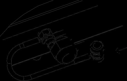
4 1 Introduction Fig. 01 LRS 04 Ex The Duct Smoke Detector LRS 04 Ex comprises the ventilation duct base LKS 02, the optical smoke switch ORS 221 Ex and the ORS 142 Ex interface (connection box). These components are fitted onto the mounting plate and prewired. It is used for smoke monitoring in ventilation ducts with potentially explosive atmospheres. The Duct Smoke Detector LRS 04 Ex is ATEX-approved and can be used in zones 1 and 2 (IBExU04ATEX1105, IBExU04ATEX1106). Duct Smoke Detector LRS 04 Ex is used for incorporation of the optical smoke switch ORS 221 Ex and is mounted on the ventilation duct from the outside. The Duct Smoke Detector LRS 04 Ex is designed for application within buildings. Caution: The specifications in the explosion protection document must be observed. The ventilation ducts must be thoroughly cleaned before taking a smoke switch in ventilation systems into operation. 4
5 2 About this document 2.1 Objectives and intended readers This document is intended to inform you about operation and installation of a electrical system in potentially explosive areas. You will find information on the following subjects: Safety Design and mode of operation Use of the product System components System integration Commissioning Servicing This document is intended for the following groups of persons: Installation planners Specialist planners Installation technicians Safety officers Service and maintenance personnel 2.2 Symbols used Some items of information in this document are specially emphasised in order to ensure quick access to such passages. Note: A note informs you about special features of the unit, explains important background information, or recommends a particular course of conduct. Warning of potential damage to equipment! This symbol is used to indicate information that is important for correct operation of the unit. Non-observance may lead to damage to the unit. Danger! This symbol is used to indicate information that is of importance for health and safety of persons. Non-observance may lead to damage to health and personal injury. 5
6 3 Safety Observe and follow the Instruction Manual! The Instruction Manual for operation and installation of smoke tripping device for smoke in potentially explosive areas is an integral part of the product. Before any handling, installation and start-up of units the following safety instructions, as well as descriptions and information about the present Instruction manual must be carefully read and observed. Caution - explosion hazard! When carrying out any work in areas in which the Duct Smoke Detector LRS 04 Ex may be installed, all necessary safety measures must be adopted to ensure that the work does not cause an explosion. Any work in hazardous areas must be authorised in writing by the responsible safety officer. It is a fundamental rule that, when planning, installing, assembling, and operating the smoke tripping device for smoke in potentially explosive atmospheres, specific national rules and regulations must be observed. In any case, the following planning information is subordinate to specific national provisions. The Directive 94/9/EC requires that the manufacturer and reseller ensure traceability of a product to the end user. The administration procedures for our products include a production number which is permanently marked on each product. Please note that the Duct Smoke Detector LRS 04 Ex has two production numbers: 1. One production number for the smoke switch sensor ORS 221 Ex E 2. One production number for the ORS 142 Ex interface Avoid damage to markings! The type plates, type designations and/or identification markings on the devices and conductor plates must not be removed, overwritten, or made illegible. 6
7 3.1 Guarantee claims In case of non-compliance with the requirements/specifications contained in this Instruction Manual any claims for guarantee and liability of the manufacturer shall become invalid. Non-compliance with this clause will result in any claims for guarantee and liability against the manufacturer of the devices becoming null and void. 7
8 4 Project planning The Duct Smoke Detector LRS 04 Ex is designed for application in rectangular ventilation ducts of 0.5 m to 1 m in diameter. In ventilation ducts with a round cross section, application is possible for Ø from 0.2 m to 1 m. The detection range to the side of the inlet tube in the channel is approx. 500 mm. The air channel base must be positioned such that reliable smoke detection can be assumed. Any interference factors that may impair safe functioning of the LRS 04 Ex must be ruled out. If required, the length of the inlet tube must be adjusted accordingly, see chapter 9 Installation. Direction of air flow A1: Ideal operating environment A2: Increased dust load B: Area not suitable for early smoke detection Hydraulic diameter Fig A recommendation for project planning is provided in Fig. 02. In order to ensure reliable smoke detection in larger channels several LRS 04 Ex should be used. In doing this, the parameters of the ventilation duct with regard to monitoring of the centre of the air flow must be observed. Fig
9 5 Technical data LRS 04 Ex Field of application Functional principle Smoke switch Response threshold Min. air flow Max. air flow Openings Current consumption with 28 V DC Quiescent In alarm In case of a failure Relay contact in Ex interface Max. switching voltage Max. switching current Switching power max. Inlet tube Round and rectangular ventilation duct with potentially explosive atmosphere of zones 1 and 2 Scattered light ORS 221 Ex According to the construction and testing principles for tripping devices for smoke (12/76) 1 m/s 20 m/s 2 x Ø mm/150 mm distance for installation in housing 3 x max. 6 mm or 3 pairs of openings for passing through 3 tensioning straps Max. 12 ma Max. 1.8 ma Max. 2.7 ma 30 V DC/30 V AC 1 A 30 W Standard length in the channel 344 mm bore diameter Ø mm Temperature range of operating environment 20 C to +70 C Degree of protection according to EN IP 54 (on duct surface) IBExU certificate number ORS 142 Ex interface IBExU 04 ATEX 1105 Colour Blue, black, white and transparent Materials PC/polyester/aluminium tube Installation On round and rectangular ventilation ducts Cable entry 2 ATEX glands M16 x 1.5 with Ø 4-8 mm and 1 mushroom plug Dimensions without pipe See dimensioned drawing (Fig. 9-01) Weight of ventilation-duct smoke switch system (incl. inlet tube and ORS 221 Ex) Equipotential bonding connection 2740 g M6 9
10 Smoke switch ORS 221 Ex Functional principle Scattered light Response threshold According to the construction and testing principles for tripping devices for smoke (12/76) Degree of protection IP 40 Ambient temperature during operation 20 C to +70 C Weight 120 g Additional output Terminal 3 (for communication only) IBExU certificate number ORS 221 Ex IBExU04ATEX1106 Terminal cross section in ORS 142 Ex Max. 1.5 mm² interface (connection box) Note: The ORS 221 Ex is automatically reset as soon as the sensing chamber is free of smoke. For alarm storage, the power supply unit or the connection box of the hold-open system FAD 01/FAK 01 can be equipped with a signalling and display control element SAB 04. Note: The ORS142 Ex interface (connection box) is prewired with the base of the optical smoke switch ORS 221 Ex at the factory. This wiring must not be changed! 10
11 6 General information 6.1 Operation of the LRS 04 Ex During operation, the air of the ventilation duct to be monitored permanently flows through the ventilation-duct smoke switch system LRS 04 Ex. As soon as smoke particles are detected, an alarm is triggered and the safety devices are activated. As soon as the sensing chamber is free of smoke particles again, the LRS 04 Ex is reset automatically. 6.2 Transport, storage and unpacking The LRS 04 Ex is delivered packed in an appropriate fitted carton. The packaging can be recycled. Please observe the packaging properties! The cardboard packaging of the LRS 04 Ex fulfills the minimum packaging requirements and when stacked, has a load-bearing capacity of up to 10 times of its own weight. The packaging is only conditionally suitable for transport by post or rail. Special packaging is available for transport in tropical zones, transport by ship, etc. For more information, please contact the manufacturer. Do not open the packaging until the unit is required for use. Retain the enclosed instructions for installation. 6.3 Scope of delivery Housing with transparent cover Inlet tube: Overall length 415 mm, with standard installation depth of 344 mm in the channel, prewired with earth cable Flow adapter ORS 221 Ex 2 ATEX glands M16 x 1.5, of which one is equipped with an Ex mushroom plug 3 LKS sealing rings 3 adhesive pads 3 self-cutting fastening screws 2 spring washers M6 2 nuts M6 Instruction manual Packaging and labelling Optical smoke switch ORS 221 Ex 11
12 7 Rules and regulations For fire protection in ventilation systems the requirements of 3 and 17 of MBO (German Model Building Regulation) apply, among others. These requirements shall be included in the building regulations of the respective country. The rules and regulations applicable in the country of use must be observed. Extract from Model Building Regulation 17: "Buildings, plants and facilities must be designed such that development and spreading of fire and smoke is prevented and in case of a fire rescue of people and animals as well as efficient fire-extinguishing measures are possible." As a general principle, all rules and regulations must be observed in parallel in case that a product falls within the scope of application of several regulations, in order to also comply with the special requirements of every regulation. 7.1 Definition of the field of application The product LRS 04 Ex is intended for smoke detection in ventilation systems in potentially explosive atmospheres. The sensor can be installed in ventilation ducts with air flow speeds between 1 m/sec. and 20 m/sec. Caution: The applicable rules and regulations must be observed for planning, designing, execution, application and maintenance. For any such rules and regulations, please consider the explosion protection document or contact the explosion protection responsible. 12
13 7.2 Safety in potentially explosive atmospheres Please observe the following rules for tripping devices for smoke in hazardous areas: The LRS 04 Ex must not be used for doors and shutters of areas in which a potentially explosive atmospheres due to combustible dust is to be assumed (zones 20 to 22). Only clean with a damp cloth or sponge! In order to avoid electrostatic charging, only use damp cloths for cleaning purposes. 7.3 Intended use The LRS 04 Ex is a tripping device for smoke for application in ventilation systems in potentially explosive atmospheres. This tripping device for smoke LRS 04 Ex is an integral part of an air-conditioning system and as such it may only be used if correctly integrated into the ventilation system Both during commissioning and operation, the safety instructions as well as the acceptance and testing provisions of the rules and regulations to be applied for this hazardous area contained in the present Instructions Manual must be observed without failure. Ensure proper use! The appliance LRS 04 Ex was developed for application in potentially explosive areas classified as zone 1 or zone 2. The technical data stated on the equipment must be observed. Modifications or changes to the equipment are not permitted. The device must be used only for its intended purpose in an undamaged and unobjectionable condition. Only the ORS 221 Ex may be used as replacement smoke switch. A work permit must be obtained from the operator/responsible person before performing any work. 13
14 7.4 General safety information and protective measures Explosion-protection regulations In Germany, the most important points with regard to putting technical equipment on the market are covered by the Eleventh Administrative Order to the Equipment and Product Safety Law 11. GPSGV. Extract from 1 "The order shall apply for putting equipment and protective systems on the market for proper use in hazardous areas." According to its intended use, equipment is divided into groups in accordance with Directive 94/9/EC, and assigned to equipment categories for proper use in hazardous areas. Extract from 3 "Equipment, protective systems, and devices [...] may not be put on the market unless they comply with the basic health and safety requirements of Directive 94/9/EC and unless they do not endanger the health and safety of persons [...] and goods, provided that they are correctly installed, maintained and properly used. The legal requirements that govern explosion protection in the workplace are not uniform. Directive 94/9/EC determines the requirements for equipment and systems. Directive 1999/92/EC is to be regarded as "user's directive". It specifies the types of equipment and systems that can be used and provides rules for operation and monitoring of plants with potential explosion hazards. In addition, there are various regulations that fall within the scope of the Equipment Safety Law and occupational health and safety regulations to be taken into account. Consideration must also be given to accident prevention rules, guidelines by the German employer's liability insurance association that may be issued for specific types of plants. The following shall apply in Germany: On the basis of the body of regulations the owner/operator shall prepare or have prepared a safety concept containing a detailed hazard analysis. In this context, a specific order of principles must be taken into account. 14
15 As a general rule, the following hierarchy of protective measures shall be observed: 1. Development of a potentially explosive atmosphere must be prevented. Primary explosion protection Sum of measures that prevent development and propagation of a potentially explosive atmosphere. 2. Ignition of a potentially explosive atmosphere must be prevented. Secondary explosion protection Sum of measures that prevent potential ignition sources from becoming effective 3. The potential impacts of an explosion must be minimised. Tertiary explosion protection Sum of measures that limit the impacts of an explosion to an innocuous level. A follow-up hazard analysis should in particular address the following points: Determination of explosion risks to which employees might be exposed Selection of appropriate measures for achieving the desired level of protection Safe layout, operation and servicing of work equipment, warning devices and protective equipment For connected areas! Areas that are or could be connected via openings to areas in which potentially explosive atmospheres may occur must also be taken into consideration for assessment of the explosion risks. 15
16 This procedure must particularly be complied with for tripping devices for smoke in ventilation systems. Work carried out in ex-zones must be properly regulated and documented. A work approval system is a suitable method of regulation the organisational aspects. The employer must ensure that employees are sufficiently and appropriately instructed and trained with regard to explosion protection. Written instructions and work approval: Warning of potential damage to equipment! Before starting with any work, a responsible person must issue a work approval. It is very important to inspect and test the systems before initial use. If required, additional measures for maintenance of explosion protection must be taken. Protective measures must be checked in regular intervals. In the event of significant changes, new measures must be adopted where appropriate. The explosion protection document must be compiled before the start of work. It must be updated on a regular basis, particularly after changes such as: Extensions Change of the workplace layout or the work procedures Use of different equipment and/or tools etc. Existing documents may be combined. 16
17 7.4.2 Classification of hazardous areas Definition of the zones in accordance with Directive 1999/92/EC Extract: Hazardous areas are classified in zones on the basis of frequency and duration of the occurrence of an explosive atmosphere. Combustible substances Dusts Gasses or vapours Frequency and duration of occurrence of the substances Permanent, long-term or frequently present Occasionally present Short-term or normally not present Permanent, long-term or frequently present Occasionally present Short-term or normally not present Zone classification Identification of equipment Equipment group Zone 20 1D Zone 21 2D or 1D Equipment category Zone 22 3D, 2D or 1D Zone 0 1G Zone 1 2G or 1G Zone 2 3G, 2G or 1G Notes: Layers, deposits and accumulations of combustible dusts must be considered in the same way as is performed for every other source leading to formation of an explosive atmosphere. The present information is intended as a summary and does not include all aspects that need to be considered. Further relevant laws, regulations and provisions applicable in the country of application must be observed as appropriate. 17

 reaches the sensor and is converted into an electrical signal.")
18 8 Product description 8.1 Design and mode of operation of LRS 04 Ex The Duct Smoke Detector LRS 04 Ex is preferably used in hazard areas classified as zone 1 or 2. It detects both smoldering fires and open fires with development of smoke at a very early stage. The Duct Smoke Detector utilises the scatteredlight principle. Inside the sensing chamber, a light source and a light sensor are arranged such that the light beam of the light source cannot directly fall on the light sensor. It is only when airborne particles enter the chamber that the light scattered by these particles (Tyndall effect) reaches the sensor and is converted into an electrical signal. The figures below illustrate the structure and layout of the ventilation-duct smoke switch system LRS 04 Ex: Cable entry 1 Cable entry 2 Equipotential bonding terminal, M6 Mounting holes Ø 6 mm Opening for tensioning strap Fig Top view LRS 04 Ex ORS 142 Ex interface (connection box) LKS 02 Inlet tube Outlet tube Fig Side view LRS 04 Ex 18
19 Wiring of the Smoke Switch: Connection of the Smoke Switch must be performed in the ORS142 Ex interface (connection box) not in the smoke switch base! 19
20 8.1.1 Terminal assignment in the connection box of the LRS 04 Ex In operation De-energised/alarm Fig Relay contacts and connection of the LRS 04 Ex Terminal 1 Terminal 2 Terminal EB Terminal EB Terminal 3 Terminal 4 Terminal 5 Terminal 6 24 V DC GND Equipotential bonding (internal only) Equipotential bonding (internal only) RS bus Potential-free relay contact: Com Potential-free relay contact: NO Potential-free relay contact: NC 8.2 Device functions and display elements of the LRS 04 Ex The evaluation electronics of the optical Smoke Switch ORS 221 Ex continuously monitor the smoke sensing unit of the detector and signal the following conditions by the integrated LED alarm: Normal operation Minor contamination Heavy contamination Failure (failure of sensing chamber) Alarm LED flashing green (approx. every 4 seconds), relay contact is closed LED flashing in alternating colours green/yellow (approx. every 4 seconds), relay contact is closed LED flashing twice in short succession green/ yellow (approx. every 4 seconds), relay contact is opened LED flashing yellow (approx. every 4 seconds), relay contact is open LED flashing red (approx. once per second), relay contact is open 20


21 8.3 Accessories for the LRS 04 Ex Power supply and tripping unit NAG 03 Front view Side view Fig Power supply and tripping unit NAG 03, front and side view The power supply and tripping unit NAG 03 is primarily used for power supply of tripping devices for smoke. It contains a power supply unit and provides stabilised nominal voltage output of 24 V DC. The maximum output current is 900 ma. For additional tasks, such as transmission of an alarm, a potential-free change-over contact is freely available. The NAG 03 is for installation in safe areas. It has protection class II. The NAG 03 does not have an inherent safety. 21
22 Technical data Nominal voltage Safety class Overvoltage category (acc. to DIN VDE ) Degree of contamination (acc. to DIN VDE ) Rated frequency Power consumption Power output Output voltage Residual ripple Ua max. Nominal current consumption Output current Relay Switchable voltage AC Switching current AC Switching voltage DC Switching current DC with 24 V DC Switching current DC with 30 V DC Housing Installation (any desired installation position, except ceiling installation) Colour Cable entry Dimensions 230 V AC "II" (protective insulation) 2 (2P) 50 Hz / 60 Hz 46 VA 21.6 W 24 V DC 120 mv PP 0.2 A eff. Max. 900 ma 1 change-over contact, potential-free Max. 250 V AC Max. 5 A Max. 30 V DC Max. 5 A Max. 3 A Degree of protection IP 30 Polycarbonate Finery/surface-mounting White 5 x max. 12 mm W 78 x H 163 x D 61 mm Ambient temperature during operation +5 C C Part number II 22

23 Fig Terminals of the power supply and tripping unit NAG 03 23
 with the signal and display control")
24 8.3.2 Signal and display control element SAB 04 Fig Optional signal and display control element SAB 04, front view The power supply and tripping unit NAG 03 can optionally be fitted (retrofitting is possible) with the signal and display control element SAB 04. After tripping of the smoke switch and after power supply failure the SAB 04 prevents automatic switch-on of the connected system components Manual actuation pushbutton 422 Ex Fig Manual actuation pushbutton 422 Ex The manual actuation pushbutton 422 Ex is used for manual actuation of fire and smoke protection flaps and control of ventilation systems in potentially explosive environments. It is suitable for application in areas with a Zone 1 and Zone 2 explosion hazard and in areas for which degree of protection IP 65 is required. The manual actuation pushbutton 422 Ex has ATEX approval. The manual actuation pushbutton 422 Ex is intended for surface installation. It is also suitable for application in moist rooms. 24
25 Technical data Type of contact Switching voltage Switching current 13 V DC V DC Ambient temperature during operation 50 C C Degree of protection IP 65 Cable entry M20 x 1.5 Cable diameters PTB No. PTB 00 ATEX 1068 Type of explosion protection Housing Dimensions without cable glands NC Max. 1 A 5 mm... 9 mm II 2 G EEx edm IIC T6 Plastic W 88.5 x H 91 x D Connection box Ex Fig Connection box Ex The Ex-connection box is suitable for application in areas with a Zone 1 and Zone 2 explosion hazard and in areas for which degree of protection IP 65 is required. The Ex-connection box is the preferred method to ensure save connec- tion of lines within a potentially explosive area. The Ex-connection box is a polyester housing, protection type Increased Safety e, with openings for cables and lines. The branching and connection box contains cable glands and terminals of protection type Increased Safety e. For protection of Ex-terminals from mechanical damage, contact, dust and humidity, the terminal must be installed in housings with Increased Safety e classification. 25
 II 2 G EEx e II T6 EC prototype test certificate number PTB 01 ATEX 1104 8.3.5 Smoke switch condition indicator RZA 142 Fig.")
26 For branch connections 2- and 3-pole insert bridges are available. Depending on the selected diameter, wire end ferruled must be used where appropriated. Unused conductors must be fixed. Technical data Ex connection box (type ) II 2 G EEx e II T6 EC prototype test certificate number PTB 01 ATEX Smoke switch condition indicator RZA 142 Fig RZA 142, front view The smoke switch status indication RZA 142 receives signals for and displays the following statuses via the communication interface Pin 3 of the LRS 04 Ex: operation, slight contamination, heavy contamination, fault or alarm. In addition to the visual indication, a potential-free change-over contact is assigned to every status; the contacts are used to transmit statuses to higher-order systems, (such as a central building control system). The RZA 142 is exclusively intended for installation in safe areas. The RZA 142 does not have inherent safety. If an RZA 142 is used in parallel to the LRS 04 Ex, the ORS 221 Ex must be re-initialised after installation of after replacement in connection with this RZA
 2. Open the housing cover at the LRS 3.")
 7. Check using test aersol 918/5 8. Insert inlet tube into the LRS 04 Ex 9.")
27 min. installation depth (5 holes) 138 ATEX Duct Smoke Detector 9 Installation directions 9.1 Mechanical installation of the LRS 04 Ex Brief overview of procedures: 1. Select the place of installation according to project design specifications (planning concept, explosion protection document, etc.) 2. Open the housing cover at the LRS 3. Mount LRS 04 Ex to the channel 4. Clean the ventilation channel and the inlet tube 5. Screw the ORS 221 Ex into the base 6. Perform wiring with auxiliary components and connect ORS 142 Ex interface (connection box) 7. Check using test aersol 918/5 8. Insert inlet tube into the LRS 04 Ex 9. Place the equipotential bonding of the inlet tube once around the base (see Fig. 9-02). 10. Connect the equipotential bonding of the inlet tube with the equipotential bonding M6 in the LRS 04 Ex using the supplied spring washer and the M6 hex nut. 11. Close the cover of the LRS 04 Ex Caution: The smoke switch LRS 04 Ex must be used together with the supplied inlet tube. The tube must not be bent! Lö ch er ) ( Direction Luftstromrichtung of air flow Ei nb Fig

 see Fig. 9-02 point into the direction of the air flow within the channel.")
28 When determining the place of installation of the LRS 04 Ex, it must be ensured that it is possible for the inlet tube to be replaced at the place of installation. For removal of the inlet tube a clearance of minimum 470 mm must be provided. During installation of the LRS 04 Ex, mounting must be with as little vibration as possible. The tube must not be bent. It must be ensured that the direction of installation of the LRS 04 Ex is corresponding to the air flow direction in the channel. For that purpose, the LRS 04 Ex must be mounted such that the arrows (marked on the bottom of the housing) see Fig point into the direction of the air flow within the channel. The LRS 04 Ex is directly mounted onto the channel axially to the direction of air flow using appropriate fastening elements and it is then sealed by means of the LKS sealing rings with adhesive pad. Fastening can be performed by means of the supplied, self-cutting screws or by means of tensioning straps. The three additional LKS sealing rings with adhesive pad are intended for smaller round channel for additional sealing. Fig Caution: When mounting the LRS 04 Ex, the direction of air flow must be observed and tightness must be ensured. 28
29 ATEX Duct Smoke Detector In case the supplied self-cutting screws (4.8 x 22) are not suitable for fastening the unit at the ventilation duct, appropriate fastening materials, such as tensioning straps must be used. The LRS 04 Ex is equipped with three 6 mm holes (see figure) and three pairs of openings for tensioning straps. Two large openings for the inlet tube and - the outlet tube are cut into the ventilation duct (see Fig. 9-03) Ø 28-30/150 mm Inlet Einlassrohr tube Opening Spannbandöffnung for tensioning strap Fastening Befesigungsbohrung hole ø 6 mm Ø 6 mm Fig Hole dimensions Opening the cover the LRS 04 Ex The LRS 04 Ex is equipped with quick fasteners for service purposes. These must only be opened if an approval for working in hazardous areas has been granted. Closing and opening of the clips can be facilitated by slightly pressing down the housing cover by hand. In case of overhead assembly of the LRS 04 Ex it must be ensured that no parts or elements (transparent cover, intake pipe, etc.) are dropped on the floor when opening the transparent cover. Handling The inherently safe wiring with the ORS 221 Ex is executed in the factory and must not be modified. The ex-protected dummy plugs must be left in the cable glands. After positive functional testing by means of test aerosol 918/5 the inlet tube with the flow adapter can be inserted. The equipotential bonding connection pre-installed at the inlet tube must also be left unchanged. Subsequently, the cover of the ventilation-duct smoke switch system LRS 04 Ex can be re-installed by slightly pressing it on and closing the clips. 29
30 Limits of application In case of interference factors arising due to operating conditions, such as, dust, smoke, humidity or steam, false alarms due to sensor deception are possible. It must be ensured that the smoke switch is not exposed to condensation. The LRS 04 Ex is not designed for outdoor applications. This information must be taken into consideration when planning and designing the system. 9.2 Electrical connection Safety notes: When introducing and fastening the cables it must be ensured that no leakages occur towards the ventilation duct. In LRS 04 Ex the LED of the ORS 221 Ex or the arrow in the base points towards the outlet tube. Correct functioning of the LRS 04 Ex is only ensured with the cover properly closed. For introduction of cables the unit is equipped with cable glands, 2 x M16, according to ATEX. With proper use, IP 54 is complied with for the sealing area of 4-8 mm. Equipotential bonding must be connected to the M6 bolt on the mounting plate as intended. The spring washers and hex nuts required, are supplied with the unit. The required cross section of the line and the properties of the cable jacket must be adapted to the conditions present. 30


31 Fig Equipotential bonding 31
32 Switching position of the relay contact in ORS 142 Ex interface Operation - Minor contamination - Heavy contamination - De-energised - Fault - Alarm Electrical installation The electrical installation must be carried out in compliance with all valid rules and regulations. Equipotential bonding via the provided connection must be made with minimum 4 mm². 32
33 Cable installation For the low voltages any conventional communication cables with or without shielding may be used. The diameter of the conductor must be selected in accordance with the current consumption of the used devices and in compliance with the length of conductors. Cable diameters max. 9 mm Recommended conductor type IY(ST)Y 4 x 2 x 0.8 mm Only conductors with the same cross section may be wired to the same terminal. The conductors must be installed such that sufficient traction relief is ensured. The cables must be selected together with the owner/operator on the basis of their required properties suitable for ex-atmosphere requirements. Load capacities of contacts Caution: The electrical limit values for load capacity of the relay contacts (30 V DC/1 A or 30 V AC/1 A) must not be exceeded, not even for short periods. Consequently, suitable measures for protection of the contacts must be taken. Safety notes: Safety-relevant shut-down / control of the system must be performed via the relay contact of the ORS 142 Ex interface, terminals 4 and 5. The operation and information statuses that are transmitted e.g. to the smoke switch status indication RZA 142 via communication interface (terminal 3) and are used for comfortable display / information and transmission to the central building control system GLT. 33


34 9.3 Switching examples For control/activation of fire and smoke protection flaps the NAG 03 should be applied. Mains supply cable 230 V AC/50 Hz N PE L Relay switched on in release condition NAG Jumper plugged to SAB 04! + - B 1 K 2 3 Activation of BSK/RSK 24 V DC Momentary switch 422 Ex 1 2 PA PA ORS142 Ex interface Interface Fig Activation of a 24V DC BSK/RSK 34


35 Activation of BSK/RSK 230 V AC Mains supply cable 230 V AC/50 Hz N PE L Relay switched on in release condition NAG SAB B 1 K Jumper plugged to SAB 04! 1 2 PA PA ORS142 Ex interface Interface Fig Activation of a 230 V AC BSK/RSK 35


36 Mains supply cable 230 V AC/50 Hz Relay switched on in release condition Jumper plugged to SAB 04! ORS221 Ex interface Fig LRS 04 Ex with mains and tripping device NAG 03 with RZA 142 Deactivation of ventilation system Mains supply cable 230 V AC/50 Hz N PE L Relay switched on in release condition NAG03 SAB Jumper wired to SAB 04! B 1 K 2 3 Activation of 24 V DC BSK/RSK e gn or T1 gr T2 rt 1 2 PA PA DKT 02 OR S221 ORS221 Ex Interface Ex interface Fig Activation of a 24V DC BSK/RSK with deactivation of ventilation system with additional DKT 02 36


37 10 Commissioning Caution: The ventilation ducts and the LRS 04 Ex must be thoroughly cleaned before taking a smoke switches in ventilation systems into operation. The smoke switches ORS 221 Ex should only be taken out of their packaging and inserted into the base of the LRS 04 Ex after cleaning is completed. 1 2 Click Klick Fig : Insertion and screwing-in of the smoke switch ORS 221 Ex 10.1 Functional testing Inspection must at least include the following aspects: Interaction of all devices and their correct technical condition must be verified. The fire protection flap / smoke protection flap and/or the ventilator must switch into safety position "closed and/or off" and remain in that position, if Smoke is detected A fault occurs at the smoke switch (e.g. due to removal of the smoke switch from the base) The energy supply fails/returns The manual actuation pushbutton is pressed For testing of smoke detection the test aerosol 918/5 should be used. The test aerosol is free from halogenated hydrocarbons (CFC and the like). If a smoke switch does not react to, i.e. is not triggered by this test, it must be replaced. The inlet openings at the inlet tube of the LRS 04 Ex must be kept unblocked. 37
38 10.2 Servicing 8 steps for easy maintenance: 1. Have the area released for work Safety notes: Any work in hazardous areas must be authorised in writing by the responsible safety officer. 2. Open housing cover by the fastening clips 3. Remove tube, inspect visually and clean if required 4. Wipe the smoke switch with a damp cloth Safety notes: In order to avoid electrostatic charging, only use damp cloths for cleaning purposes. 5. Spray test aersol 918/5 onto the smoke switch 7. Insert tube 8. Close housing cover by the fastening clips The described tests and maintenance must only be carried out by an expert of a specially qualified person. The tests and the respective results must be recorded in a test log, e.g. IW-Set BSK/RSK by AP. Caution: ORS 221 Ex and ORS 142 Ex are not compatible. Do not use aggressive cleaning agents Aggressive cleaning agents such as solvents, benzene or other alcohol-containing substances as well as cleaning agents containing chemical additives must not be used for cleaning. Caution: The warning and safety information printed on the test aerosol cylinder must always be observed! 38
39 10.3 Display of operating statuses of the ORS 221 Ex Condition Display Relay contact Normal operation Minor contamination Heavy contamination Failure (failure of sensing chamber) Alarm LED flashing green (approx. every 4 seconds) LED flashing in alternating colours green/yellow (approx. every 4 seconds) LED flashing twice in short succession, in alternating colours green/yellow (approx. every 4 seconds) LED flashing yellow (approx. every 4 seconds), relay contact is open LED flashing red (approx. once per second) Relay contact is closed Relay contact is closed Relay contact is open Relay contact is open Relay contact is open 39
40 11 Provisions for maintenance and servicing The rules and regulations for hazard areas and the provisions of the BG Chemie must be complied with. The LRS 04 Ex system should be kept operational at all times and be serviced at least once per year according to manufacturer information in compliance with the basic principles for maintenance and according to the rules and regulations applicable for the specific hazard area in accordance with DIN in connection with DIN EN In consideration of the special conditions of the operation environment, the AP Duct Smoke Detector must be subjected to servicing and maintenance according to VDE 0833 Part 1. We recommend to subject the Duct Smoke Detector to a work revision procedure after an operation period of 8 years. Work revision may be required at an earlier stage due to special conditions present in the operation environment: e.g. excessive strain, severe external influences, contamination, etc. Caution: Before any maintenance work, a work approval must be obtained and the hazard area must be de-energised. For function testing of the smoke switch ORS 221 Ex the test aerosol 918/5 by AP should be used. Caution: Interaction of all devices and their correct functioning must be verified. Caution: The inlet tube is to be checked during regular visual inspection. For visual inspection, remove the inlet tube from the LRS 04 Ex and remove any present residue. After visual inspection and possibly cleaning, re-insert the inlet tube correctly. Safety notes: The smoke switch ORS 221 Ex must not be opened! 40
41 12 Ordering data Designation Order no. LRS 04 Ex Spare smoke switch ORS 221 Ex Spare base 143 A Signal and display control element SAB Ex connection box (Type ) LKS inlet tube Ex Power supply unit NAG Power supply unit NAG 03 with SAB Power supply unit NAG Connection box for hold-open device FAD Connection card for hold-open device FAK Test Aersol 918/ IW Set BSK/RSK
42 Instruction manual LRS 04 Ex VMS Version 12/10/ Caution: Depending on the printer settings in your PC the dimensions of the drilling template may be distorted. Please deactivate the setting "adjust to page margins" when printing. To be on the safe side, verify that the dimensions of the template are correct before drilling the holes. Ø 6 mm/206 mm Ø mm/150 mm
43
Installation and Operating Instruction
 Installation and Operating Instruction Automatic Fire Detectors Series 900 Ex (i) 9893 0.00 GB Technical changes reserved! 0 Installation and Operating Instruction Automatic Fire Detectors Series 900 Ex
On the job around the clock 24/7: Fire detection systems
 On the job around the clock 24/7: Fire detection systems Version 02.2010 Version: 02.2010 Product catalogue Fire detection systems This product catalogue is intended for sales purposes only. For planning,
SCHMIDT LED Measured Value Display MD Instructions for Use
 SCHMIDT LED Measured Value Display MD 10.010 Instructions for Use Table of Contents 1 Important Information... 3 2 Application range... 4 3 Mounting instructions... 4 4 Electrical connection... 6 5 Signalizations...
Additional Operating Instructions SITRANS F. Vortex flowmeters. SITRANS FX330 Ex-nA.
 Additional Operating Instructions SITRANS F Vortex flowmeters Ex-nA Edition 08/207 CONTENTS Safety instructions 3. General notes... 3.2 EU conformity... 3.3 Approval according to the IECEx scheme... 3.4
Additional Operating Instructions SITRANS F. Vortex flowmeters. SITRANS FX330 Ex-i.
 Additional Operating Instructions SITRANS F Vortex flowmeters Ex-i Edition 09/2018 CONTENTS 1 Safety instructions 3 1.1 General notes... 3 1.2 EU conformity... 3 1.3 Approval according to the IECEx scheme...
SET-2000 Oil/Sludge. Alarm Device for Oil Separators. Installation and Operating Instructions
 SET-000 Oil/Sludge Alarm Device for Oil Separators Copyright 007 Labkotec Oy We reserve the right for changes without notice TABLE OF CONTENTS GENERAL... INSTALLATION... 4. SET-000 Oil/Sludge Control Unit...
Additional Operating Instructions SITRANS F. Vortex flowmeters. SITRANS FX330 Ex-d.
 Additional Operating Instructions SITRANS F Vortex flowmeters Ex-d Edition 09/208 CONTENTS Safety instructions 3. General notes... 3.2 EU conformity... 3.3 Approval according to the IECEx scheme... 3.4
MBZ300. Emergency power control unit. GB Installation instructions MBZ300 MBZ300 MBZ300 MBZ300 MBZ300 MBZ300 MBZ300 PME PME. Reset.
 24V 24V PME PME CM DM SM DM WM Reset Reset Emergency power control unit GB Installation instructions 1 Table of contents 1 Symbols and illustrations...3 2 Product liability...3 3 Safety instructions...3
AirUnit. Operating manual. mfh systems modern floor heating. Decentralised domestic ventilation
 mfh systems modern floor heating AirUnit Decentralised domestic ventilation Operating manual List of contents, Operating manual Page 1. General information... 02 2. Device description... 03 3. Adjustment
SET-2000 Hi Level/Oil
 Labkotec Oy Labkotie 1 FI-36240 KANGASALA FINLAND Tel: + 358 29 006 260 Fax: + 358 29 006 1260 13.03.2008 Internet: www.labkotec.fi Alarm Device for Oil Separators Copyright 2008 Labkotec Oy We reserve
Test Unit GTL 100 for Fire Detectors
 Test Unit GTL 100 for Fire Detectors Description and Operation Manual Zertifiziertes QM System Nach DIN EN ISO 9001 Description and Operation Manual Table of Contents 1. Instructions 1.1 General 1.2 Standards
M-Sens 2. Online-Moisture Meter for Solids. Operating Instructions. SWR engineering Messtechnik GmbH
 EN M-Sens 2 Operating Instructions Online-Moisture Meter for Solids SWR engineering Messtechnik GmbH CONTENTS Page 1. System Overview......................................................................
GSME Tester GTL-2. Operating manual GTL EN10. GTE Industrieelektronik GmbH
 GTL-2 430-2410-101 EN10 EN Operating manual GSME Tester GTL-2 GTE Industrieelektronik GmbH Helmholtzstr. 21, 38-40 D-41747 Viersen, GERMANY info@gte.de +49(0)2162 / 3703-0 www.gte.de Operating manual Dokument
OilSET-1000 (12 VDC)
") Labkotec Oy Myllyhaantie 6 FI-33960 PIRKKALA FINLAND Tel: +358 29 006 260 Fax: +358 29 006 1260 Internet: www.labkotec.fi 20.03.2009 1/11 OilSET-1000 (12 VDC) Oil Separator Alarm Device Copyright 2009
Labkotec Oy Myllyhaantie 6 FI-33960 PIRKKALA FINLAND Tel: +358 29 006 260 Fax: +358 29 006 1260 Internet: www.labkotec.fi 20.03.2009 1/11 OilSET-1000 (12 VDC) Oil Separator Alarm Device Copyright 2009
Flammable gases Detectors. Model DAX 03F DAX 03F- C DAX 03F- H. Note for installation, use and maintenance. Version 1.2
 Flammable gases Detectors Model DAX 03F DAX 03F- C DAX 03F- H Note for installation, use and maintenance Version 1.2 Introduction This handbook must be read carefully by any person who has or will have
SET Installation and Operating Instructions. Level switch for one sensor
 Labkotec Oy Myllyhaantie 6 FI-33960 PIRKKALA FINLAND Tel.: +358 29 006 260 Fax: +358 29 006 1260 7.11.2013 Internet: www.labkotec.fi 1/14 SET-1000 Level switch for one sensor Copyright 2013 Labkotec Oy
Original operating instructions Safety switch with guard locking AC901S AC902S
 Original operating instructions Safety switch with guard locking AC901S AC902S 7390914/03 01/2017 Contents 1 Preliminary note...4 1.1 Explanation of symbols...4 2 Safety instructions...4 3 Items supplied...5
OilSET Installation and Operating Instructions. Oil Separator Alarm Device with SET/DM3AL sensor
 Labkotec UK Ltd Adminicle House 1 Lumb Lane Audenshaw Manchester M34 5WH GREAT BRITAIN Tel: 0844 3350 477 Fax: 0161 4281 179 E-mail: info@labkotec.co.uk 10.8.2012 Internet: www.labkotec.co.uk 1/13 OilSET-1000
TIH 300 S / TIH 400 S / TIH 500 S / TIH 700 S / TIH 900 S / TIH 1100 S
 TIH 300 S / TIH 400 S / TIH 500 S / TIH 700 S / TIH 900 S / TIH 1100 S EN OPERATING MANUAL INFRARED HEATING PANEL TRT-BA-TIH300S-TIH400S-TIH500S-TIH700S-TIH900S-TIH1100S-TC-002-EN Table of contents Notes
ExDetector IRCO2. ExDetector IRHC. Operating and Installation Instructions. Gas Detection and Warning Systems
 IRCO2 IRHC Operating and Installation Instructions Gas Detection and Warning Systems Important Instructions Prerequisites for safe and reliable operation of the system: Appropriate transport and handling
Operating Manual MS220KA and MSR220KA
 Temperature Relays and MINIKA, Mains Monitoring, Digital Panel meters MINIPAN, Switching Relays and Controls Operating Manual MS220KA and MSR220KA ZIEHL industrie elektronik GmbH + Co KG Daimlerstraße
VERSAFLOW VORTEX Supplementary instructions
 VERSAFLOW VORTEX Supplementary instructions Vortex flowmeter Equipment category II 2G CONTENTS VERSAFLOW VORTEX 1 Safety instructions 3 1.1 General notes... 3 1.2 EC conformity... 3 1.3 Approval according
M-Sens 2. Online moisture measurement for solids. Operating Instructions. SWR engineering Messtechnik GmbH PART OF THE ENVEA GROUP
 EN M-Sens 2 Operating Instructions Online moisture measurement for solids SWR engineering Messtechnik GmbH PART OF THE ENVEA GROUP CONTENTS Page 1. System overview.............................................
SET-2000 Oil/Sludge 12 VDC
 Labkotec Oy Myllyhaantie 6 FI-33960 PIRKKALA FINLAND Tel: + 358 29 006 260 Fax: + 358 29 006 1260 12.2.2015 Internet: www.labkotec.fi 1/14 SET-2000 Oil/Sludge 12 VDC Alarm Device for Oil Separators with
OilSET Installation and Operating Instructions. Oil Separator Alarm Device
 Labkotec Oy Myllyhaantie 6 FI-33960 PIRKKALA FINLAND Tel: +358 29 006 260 Fax: +358 29 006 1260 18.11.2010 Internet: www.labkotec.fi 1/10 OilSET-1000 Oil Separator Alarm Device Copyright 2010 Labkotec
Operating instructions Safety-monitoring module SRB 302X3. 1 About this document
 1 About this document Operating instructions... pages 1 to 6 Translation of the original operating instructions 1.1 Function This operating instructions manual provides all the information you need for
Procedure for the Approval of New Fire Detection and Alarm Technologies
 VdS Guidelines for Automatic Fire Detection and Fire Alarm Systems VdS 3469en Procedure for the Approval of New Fire Detection and Alarm Technologies VdS 3469en : 2016-01 (01) Publisher and publishing
Conductive Leakage detectors of the Leckstar range
 Conductive Leakage detectors of the Leckstar range with electrode and relay Jola Spezialschalter GmbH & Co. KG Klostergartenstr. 11 67466 Lambrecht (Germany) Tel. +49 6325 188-01 Fax +49 6325 6396 www.jola-info.de
Flameproof Manual Call Points
 Operating instructions Additional languages www.r-stahl.com CS & Clifford & Snell Contents General Information.... Manufacturer.... Information regarding the operating instructions.... Further documents....
Operating Instructions
 Operating Instructions ProVicom MT-65, MT-125 R. STAHL HMI Systems GMBH Im Gewerbegebiet Pesch 14 50767 Köln Version 1.7 Issue: 21.07.2008 R. STAHL HMI Systems GmbH / OperatingInstruction_Provicom_Falcon_en_1_7.doc
Fire Detection Systems Product Catalogue (Version )
") Fire Detection Systems Product Catalogue (Version 2015-01) Version 2015-01 Product Catalogue Fire Detection Systems This product catalogue is intended for sales purposes only. For planning, installation,
Fire Detection Systems Product Catalogue (Version 2015-01) Version 2015-01 Product Catalogue Fire Detection Systems This product catalogue is intended for sales purposes only. For planning, installation,
3. Intended use. 4. Function. 1. Product characteristics. 2. Safety. Functional description. Channel A light. Motion detector
 EN Motion detector themova S360-101 DE WH 1030565 themova S360-101 DE GR 1030566 themova S360-101 AP WH 1030555 themova S360-101 AP GR 1030556 1. Product characteristics 307067 Passive infra-red motion
1. Product characteristics 4 2. Safety 5 3. Proper use 5 4. Operation 6
 307214 1103107701 EN Presence detector theronda S360-101 DE WH 2080565 theronda S360-101 DE GR 2080566 theronda S360-101 AP WH 2080555 theronda S360-101 AP GR 2080556 1. Product characteristics 4 2. Safety
OPTIBAR P 1010/2010 C Supplementary instructions
 OPTIBAR P 1010/2010 C Supplementary instructions Pressure transmitter Equipment category II 1G / Ga, II 1D / Da in protection type intrinsic safety Exi KROHNE CONTENTS OPTIBAR P 1010/2010 C 1 Safety instructions
2CKA001473B System Manual Busch-Infoline. Handicapped toilet signal set 1510 UC
 2CKA001473B9007 19.05.2017 System Manual Busch-Infoline Handicapped toilet signal set 1510 UC-... -101 Table of contents Table of contents 1 Notes on the instruction manual... 3 2 Safety... 4 2.1 Information
AirUnit. Installation instructions. mfh systems modern floor heating. Decentralised domestic ventilation
 mfh systems modern floor heating AirUnit Decentralised domestic ventilation Installation instructions List of contents, Installation instructions Page 1. General information... 03 2. Function / planning
Instructions for the BASIC BCRW Fan, Sizes General
 Instructions for the BASIC BCRW Fan, Sizes 004 027 1. General The BCRW is a direct-driven fan of axi-centrifugal design. This fan offers excellent power efficiency, low, uniform air flow, low sound generation
STAINLESS STEEL FLAMMABLE GAS DETECTOR DAX 3F-I INSTALLATION, OPERATING AND MAINTENANCE INSTRUCTIONS. DAX3FI_MAN01_EN Ver. V1R2
 STAINLESS STEEL FLAMMABLE GAS DETECTOR INSTALLATION, OPERATING AND MAINTENANCE INSTRUCTIONS DAX3FI_MAN01_EN Ver. V1R2 1 Introduction These instructions must be read carefully by any person who has or will
Operating instructions Safety-monitoring module SRB 302X3. 1. About this document. Content
 8 Appendix 8.1 Wiring examples...4 8.2 Start configuration...4 8.3 Sensor configuration...4 8.4 Actuator configuration...5 Operating instructions.............pages 1 to 6 Original 9 EU Declaration of conformity
GMA200-MW16. Operation Manual. Gas detection controller for wall mounting
 Operation Manual GMA200-MW16 Gas detection controller for wall mounting GfG GESELLSCHAFT FÜR GERÄTEBAU MBH KLÖNNESTRASSE 99 44143 DORTMUND, GERMANY TEL. +49 / (0)231 / 564 00 0 FAX +49 / (0)231 / 516 313
Operating instructions
 MA00929301 09/2015 Operating instructions ED10429002 ESYLUX GmbH An der Strusbek 40 22926 Ahrensburg Germany info@esylux.com www.esylux.com 1 Table of contents 1 Using the manual 8 2 Safety instructions
Translation of the assembly instructions with operating instructions and technical appendix
 BA Ex-SBU Switch box type SBU-x(1,2,3)x Translation of the assembly instructions with operating instructions and technical appendix In accordance with EU ATEX Directive 2014/32/EU In accordance with EU
Inductive slot sensor
 0102 Model Number Features 2 mm slot width Technical Data specifications Switching function Normally closed (NC) Output type NAMUR Slot width 2 mm Depth of immersion (lateral) 5... 7 mm, typ. 6 mm Output
Rules for Intruder Alarm Systems
 Rules for Intruder Alarm Systems Opening detectors (Magnetic contacts) Part 1: Requirements VdS 2120en 03/96 (03) Subject 44 1 General; 2 Terms and definitions; 3 Classification 1 General 1.1 Scope These
Capacitive leakage detectors of the Leckmaster range for installation in normally dry rooms
 Capacitive leakage detectors of the Leckmaster range for installation in normally dry rooms Jola Spezialschalter GmbH & Co. KG Klostergartenstr. 11 67466 Lambrecht (Germany) Tel. +49 6325 188-01 Fax +49
ED820-24V MODEL INSTRUCTION MANUAL. fire DETECTOR
 ED820 24V MODEL fire DETECTOR INSTRUCTION MANUAL Address: Enigma House, Enigma Business Park, Malvern, Worcestershire, WR14 1GD Tel: 44 (0)1684 891500 Fax: 44 (0)1684 891600 Email: sales@electronicdevices.co.uk
FlowJam S Ex. Bulk Flow Detection. Operating Instructions. SWR engineering Messtechnik GmbH
 EN FlowJam S Ex Operating Instructions Bulk Flow Detection SWR engineering Messtechnik GmbH CONTENTS Page 1. Function.......................................................................... 3 2. Safety..............................................................................
Connections, displays and operating elements C D E G H. Installing the control unit
 1 2 3 GB Control unit 0-10 V REG-K/3-gang with manual mode Operating instructions Art. no. MTN646991 ¼ DANGER Risk of fatal injury from electrical current. All work on the device should only be carried
Technical Data. General specifications Switching element function Rated operating distance s n 5 mm
 0102 Model Number Features 5 mm non-flush Usable up to SIL2 acc. to IEC 61508 Technical Data specifications Switching element function NAMUR, NC Rated operating distance s n 5 mm Installation non-flush
BSK-RPR Fire Damper. Additional operating instructions according to
 Additional operating instructions according to BSK-RPR Fire Damper Contents GENERAL CONDITIONS... 1 DESCRIPTION... 3... 4 EC Certificate of Conformity 0761 CPD 0245 Declaration of Performance 09-22-DoP-BSK-RPR-2013-07-01
Technical Data. General specifications Switching element function Rated operating distance s n 5 mm
 0102 Model Number Features 5 mm flush Usable up to SIL 3 acc. to IEC 61508 Application Danger! In safety-related applications the sensor must be operated with a qualified fail safe interface from Pepperl+Fuchs,
Immersion heating type FL65.. PTB 97 ATEX 1027 X. March thuba Ltd. CH-4015 Basle Telefon Telefax
 Immersion heating type FL65.. PTB 97 ATEX 1027 X March 1999 thuba Ltd. CH-4015 Basle Telefon +41 061 307 80 00 Telefax +41 061 307 80 10 Headoffice@thuba.com www.thuba.com Manual PTB 97 ATEX 1027 X 2 Immersion
BKA-EN Fire Damper. Additional operating instructions according to
 Additional operating instructions according to BKA-EN Fire Damper Contents GENERAL CONDITIONS... 1 DESCRIPTION... 3... 4 EC Certificate of Conformity 0761 CPD 0244 Declaration of Performance 09-19-DoP-BKA-EN-2013-07-01
INSTRUCTION MANUAL T30 1MN0107 REV. 0. operates with ISO9001 certified quality system
 INSTRUCTION MANUAL 1MN0107 REV. 0 operates with ISO9001 certified quality system TECSYSTEM S.r.l. 20094 Corsico (MI) Tel.: +39-024581861 Fax: +39-0248600783 http://www.tecsystem.it R. 1.1 25/08/16 ENGLISH
GL-CO-RFG Channel Gas Leak Alarm System
 Four Elms Road Edenbridge Kent TN8 6AB UK Features & Benefits Remote sensors for natural gas, LPG and CO 1 x SPST relay outputs DIN-rail as standard, panel mounting kit available Adjustable alarm thresholds
Technical Ventilation
 About ventilation of cabinets Nearly all governments place duties on employers to eliminate or control the risks from explosive atmospheres in the workplace. When it comes to storing flammables, the risk
OPTISENS TUR 2000 Technical Datasheet
 OPTISENS TUR 2000 Technical Datasheet Sensor for turbidity measurement in water and wastewater Rugged design for harsh applications Integrated transmitter with direct 4...20 ma output Near infrared light
GMA200-MT. Operation Manual. Gas detection controller for mounting rail assembly
 Operation Manual GMA200-MT Gas detection controller for mounting rail assembly GfG GESELLSCHAFT FÜR GERÄTEBAU MBH KLÖNNESTRASSE 99 44143 DORTMUND, Germany TEL. +49 / (0)231 / 564 00 0 FAX +49 / (0)231
FLAMMABLE GAS DETECTOR DAX 3F-C INSTALLATION, OPERATING AND MAINTENANCE INSTRUCTIONS. DAX3FC_MAN01_EN.indd Ver. V1R2
 FLAMMABLE GAS DETECTOR INSTALLATION, OPERATING AND MAINTENANCE INSTRUCTIONS DAX3FC_MAN01_EN.indd Ver. V1R2 Introduction These instructions must be read carefully by any person who has or will have the
SCHMIDT Flow Sensor SS Ex - Supplementary instructions for use in explosive atmospheres ATEX
 SCHMIDT Flow Sensor SS 20.600 Ex - Supplementary instructions for use in explosive atmospheres ATEX SCHMIDT Flow Sensor SS 20.600 Ex ATEX version Table of Contents 1 Important information... 3 2 Storage
FP120-Z1 Power supply kit A (70 W) Technical Manual
 Technical Manual") FP120-Z1 Power supply kit A (70 W) Technical Manual 2015-07-08 Control Products and Systems Legal notice Legal notice Technical specifications and availability subject to change without notice. Transmittal,
FP120-Z1 Power supply kit A (70 W) Technical Manual 2015-07-08 Control Products and Systems Legal notice Legal notice Technical specifications and availability subject to change without notice. Transmittal,
Operating Instructions. Accessory Units Melitta Cafina XT Series. Melitta Professional Coffee Solutions
 Operating Instructions Accessory Units Melitta Cafina XT Series Melitta Professional Coffee Solutions Contents General... 4. Manufacturer information... 4.2 About these instructions... 4.3 Explanation
Inspection Light LED 6149/2. Operating instructions EN EN EN EN EN EN EN EN EN EN EN EN EN EN EN EN EN EN EN EN EN EN EN EN
 Inspection Light LED Operating instructions Additional languages www.stahl-ex.com Contents 1 General Information...3 1.1 Manufacturer...3 1.2 Information regarding the operating instructions...3 1.3 Conformity
Index I. INSTALLATION DIAGRAM... WIRING DIAGRAMS...
 Index I. INSTALLATION DIAGRAM... 4 II. III. WIRING DIAGRAMS...... 1. Wiring diagram AC 3-N-400 50/60 Hz... 2. Wiring diagram AC 3-230 50/60 Hz...... 3. Wiring diagram AC 230 50/60 Hz... 4. Series 30 electrical
Protecting you and your home
 Gira smoke alarm device Dual Q Dual Q sounds the alarm when dangerous smoke formation is detected and fulfils the increased Q-Label quality requirements. Dual Q is a combined heat and smoke detector, thanks
Installation and operating instructions. Temperature difference controller 6 inputs, 3 outputs, integrated data logger for SD card
 SOLARTHERMIE - SOLAR THERMAL - SOLAR TÉRMICO - SOLAIRE THERMIQUE - SOLARE TERMICO Installation and operating instructions Temperature difference controller 6 inputs, 3 outputs, integrated data logger for
Snifter ATEX22 VERSION. User Manual. Distributor
 Snifter ATEX22 VERSION User Manual Distributor Version 1.4 09/09/2009 Table of Contents 1. INTRODUCTION... 3 1.1. Safety... 3 1.2. Product overview... 4 1.3. How does it work?... 4 2. INSTALLATION... 5
DICTATOR Hold-Open Systems for Hazardous Areas
 DICTATOR for Hazardous Areas Products to be used in hazardous areas obviously have to meet special demands. The European ATEX directives (first the EN 94/9/EG and then the directive 2014/34/ EU) brought
7XG3120 ReyArc20 Arc Fault Monitor Relay Energy Management
 Reyrolle Protection Devices 7XG3120 ReyArc20 Arc Fault Monitor Relay Energy Management 7XG3120 - Arc Fault Monitor Relay The over-current caused by an arc is, due to its resistance, lower than the over-current
AIRGOCLEAN 10 E OPERATING MANUAL AIR CLEANER TRT-BA-AIRGOCLEAN10E-TC-001-EN
 AIRGOCLEAN 10 E EN OPERATING MANUAL AIR CLEANER TRT-BA-AIRGOCLEAN10E-TC-001-EN Table of contents Notes regarding the operating manual... 1 You can download the current version of the operating manual and
ANNEX AMENDMENTS TO THE INTERNATIONAL CODE FOR FIRE SAFETY SYSTEMS (FSS CODE) CHAPTER 1 GENERAL
 CHAPTER 1 GENERAL") Annex 2, page 2 ANNEX AMENDMENTS TO THE INTERNATIONAL CODE FOR FIRE SAFETY SYSTEMS (FSS CODE) CHAPTER 1 GENERAL Section 1 Application 1 The following new sentence is added to the end of paragraph 1.2:
Annex 2, page 2 ANNEX AMENDMENTS TO THE INTERNATIONAL CODE FOR FIRE SAFETY SYSTEMS (FSS CODE) CHAPTER 1 GENERAL Section 1 Application 1 The following new sentence is added to the end of paragraph 1.2:
ORIGA-SENSOFLEX Displacement Measuring System for Cylinder Series OSP-P
 ORIGA-SENSOFLEX Displacement Measuring System for Cylinder Series OSP-P Contents Description Data Sheet No. Page Overview P-1.50.001E 117-118 Technical Data SFI-plus P-1.50.002E-1, 2 119-120 Dimensions
1U ULTRA Compact System
 en atel Supervisory Module SM32 Load 60 00 A IE C60947-2 G B140 4 8.2 CHNT NB1-63 C32 23 0/40 0 V e NaT el OK enatel RM 1848 enatel RM 1848 Battery 60 00A IE C60947-2 G B1 4 04 8.2 CHNT NB 1-63 C32 23
Installation, Operating and Maintenance Manual
 STATUS ZONES CONTROLS FIRE FAULT DISABLED FIRE 1 2 3 4 5 6 7 8 TEST FAULT DISABLED 1 5 BUZZER SILENCE RESET 1 2 TEST 2 6 LAMP TEST 3 SUPPLY 3 7 SYSTEM FAULT 4 8 SOUNDERS ACTIVATE/ SILENCE 4 FAULTS INSTRUCTIONS
INLINE CENTRIFUGAL FAN. Centro-M OPERATION MANUAL
 INLINE CENTRIFUGAL FAN OPERATION MANUAL www.blaubergventilatoren.de CONTENT 3 Introduction 3 General 3 Safety rules 3 Transport and storage requirements 3 Manufacturer's warranty 4 Fan design 4 Delivery
Smoke Fire Damper Interface (230V)
") Always READ this document BEFORE INSTALLATION. Please Retain for future reference. This product forms part of a life safety system. Failure to correctly store, handle, install and maintain the product
Always READ this document BEFORE INSTALLATION. Please Retain for future reference. This product forms part of a life safety system. Failure to correctly store, handle, install and maintain the product
Instruction Manual. Alarm Unit For Low Gas Level # Read manual before use! Observe all safety information! Keep manual for future use!
 Mess-, Regel- und Überwachungsgeräte für Haustechnik, Industrie und Umweltschutz Lindenstraße 20 74363 Güglingen Telefon +49 7135-102-0 Service +49 7135-102-211 Telefax +49 7135-102-147 info@afriso.de
MANUAL Overflow sensor NVF-104/34-PF
 PROCESS AUTOMATION MANUAL Overflow sensor NVF-104/34-PF ISO9001 0102 Overflow sensor NVF-104/34-PF With regard to the supply of products, the current issue of the following document is applicable: The
Supplement to operating and installation manual no for the VR 81 remote control unit
 Supplement to operating and installation manual no. 0020044392 for the VR 81 remote control unit The VR 81/2 remote control unit can be used together with the VRC 430/VRC 430f and VRC 470 compensator types.
Technical Data. Dimensions
 0102 Model Number Features 5 mm flush Usable up to SIL2 acc. to IEC 61508 Accessories EXG-18 Quick mounting bracket with dead stop BF 18 Mounting flange, 18 mm Technical Data specifications Switching element
INSTRUCTION MANUAL IS-mB1 Minialite Intrinsically Safe Round LED Beacon
 INSTRUCTION MANUAL Minialite Intrinsically Safe Round LED This instruction sheet describes installations which conform to EN60079:Part14:2008 Electrical Installation in Hazardous Areas. When designing
Instruction Manual. Electronic gas and smoke detector GRM
 Mess-, Regel- und Überwachungsgeräte für Haustechnik, Industrie und Umweltschutz Lindenstraße 20 DE-74363 Güglingen Telefon +49(0)7135-102-0 Service +49(0)7135-102-211 Telefax +49(0)7135-102-147 E-Mail
PROTECT SRB 200EXi-1A
 2 Installation up to zone 1/21 J S L1 0V X1 X3 S11 S12 S21 S22 Installation up to zone 2 A1 F1 F2 U B U EXi U i 0V S12 S22 X1 X3 K1 Logic K2 K1 K2 13 23 U EXi SRB 200EXi U B -1A U i K1 K2 PA PA A1 A2 13
Operating Manual MS220DA
 ZIEHL industrie elektronik GmbH + Co KG Daimlerstraße 13, D 74523 Schwäbisch Hall + 49 791 504-0, info@ziehl.de, www.ziehl.de Temperature Relays and MINIKA Mains Monitoring Digital Panel Meters MINIPAN
GMA 301. Operation Manual. Worldwide Supplier of Safety Solutions. Part Number
 Worldwide Supplier of Safety Solutions GfG Instrumentation 1194 Oak Valley Drive #20 Phone: 734-769-0573 Fax: 734-769-1888 E-Mail: info@gfg-inc.com Internet: www.gfg-inc.com GMA 301 Operation Manual Part
PROZESSAUTOMATION. Manual SEGMENT PROTECTOR R-SP-!12. Zone 1 Zone 2 / Div 2 FNICO
 PROZESSAUTOMATION Manual SEGMENT PROTECTOR R-SP-!12 FieldConnex TM Segment Protectors with overloaod protection and short-circuit current limitation for the connection of 12 field devices Zone 1 Zone 2
Control and Indicating Equipment
 VdS Guidelines for Fire Detection and Fire Alarm Systems VdS 2540en Requirements and Test Methods VdS 2450en : 2018-12 (03) Publisher and publishing house: VdS Schadenverhütung GmbH Amsterdamer Str. 172-174
Users Manual. Gas wall hung Boiler condensing Buderus /S. Please read thoroughly before operating the unit
 7215 3200-02/2006 GB (EN) For the user Users Manual Gas wall hung Boiler condensing Buderus 500-24/S Please read thoroughly before operating the unit Introduction Please read these instructions and follow
INSTRUCTION MANUAL T119 1MN0110 REV. 0. operates with ISO9001 certified quality system
 INSTRUCTION MANUAL 1MN0110 REV. 0 operates with ISO9001 certified quality system TECSYSTEM S.r.l. 20094 Corsico (MI) Tel.: +39-024581861 Fax: +39-0248600783 http://www.tecsystem.it R. 1.1 25/08/16 ENGLISH
Insulation fault evaluator EDS460-DG
 Insulation fault evaluator for localising insulation faults in DC IT systems with a number of branch circuits where high system leakage capacitances are involved Preliminary data sheet TDB108021en/09.2008
PEPPERL+FUCHS GmbH
 Comfort series 1.5 mm embeddable M8x1 4 25 16 13 LED Switching element function NAMUR NC Rated operating distance s n 1,5 mm Installation embeddable Assured operating distance s a 0... 1,215 mm Reduction
MANUAL Oil Level Sensor
 PROCESS AUTOMATION MANUAL Oil Level Sensor KVF-104-PF ISO9001 0102 With regard to the supply of products, the current issue of the following document is applicable: The General Terms of Delivery for Products
Technical Data. General specifications Switching element function Rated operating distance s n 4 mm
 0102 Model Number Features 4 mm non-flush Accessories BF 12 Mounting flange, 12 mm Technical Data specifications Switching element function NAMUR, NO Rated operating distance s n 4 mm Installation non-flush
Immersion heating type IN 16.. PTB 99 ATEX 1009 U. May thuba Ltd. CH-4015 Basle Telefon Telefax
 Immersion heating type IN 16.. PTB 99 ATEX 1009 U May 1999 thuba Ltd. CH-4015 Basle Telefon +41 061 307 80 00 Telefax + 41 061 307 80 00 headoffice@thuba.com www.thuba.com Manual PTB 99 ATEX 1009U 2 Immersion
5U Compact System. Installation Manual V1.0. Manufactured by Enatel Ltd. 321 Tuam Street PO Box Christchurch New Zealand
 5U Compact System Installation Manual V1.0 Manufactured by Enatel Ltd. 321 Tuam Street PO Box 22-333 Christchurch New Zealand Phone +64-3-366-4550 Fax +64-3-366-0884 Email sales@enatel.net www.enatel.net
ISOSCAN EDS460-DG. Insulation fault locator for DC IT systems with high system leakage capacitances
 ISOSCAN Insulation fault locator for DC IT systems with high system leakage capacitances _D00108_00_D_XXEN/05.2015 ISOSCAN Insulation fault locator for DC IT systems with high system leakage capacitances
Interface and EOL Modules 8
 Interface and EOL Modules Interface Modules Series 420 25 Interface Modules Series 100 291 EOL Modules 293 254 Interface and EOL Modules Interface Modules Series 420 Interface Modules Serie 420 Interface
GMA200-MW4. User Manual. Gas detection controller for wall mounting
 User Manual GMA200-MW4 Gas detection controller for wall mounting GfG GESELLSCHAFT FÜR GERÄTEBAU MBH KLÖNNESTRASSE 99 44143 DORTMUND, GERMANY TEL. +49 / (0)231 / 564 00 0 FAX +49 / (0)231 / 516 313 INFO@GFG-MBH.COM
Smoke Damper Interface (230V)
") Always READ this document BEFORE INSTALLATION. Please Retain for future reference. This product forms part of a life safety system. Failure to correctly store, handle, install and maintain the product
Always READ this document BEFORE INSTALLATION. Please Retain for future reference. This product forms part of a life safety system. Failure to correctly store, handle, install and maintain the product
Fire Damper Interface (24V)
") Always READ this document BEFORE INSTALLATION. Please Retain for future reference. This product forms part of a life safety system. Failure to correctly store, handle, install and maintain the product
Always READ this document BEFORE INSTALLATION. Please Retain for future reference. This product forms part of a life safety system. Failure to correctly store, handle, install and maintain the product