Digital Temperature Controller E5AZ
|
|
|
- Lawrence Grant
- 5 years ago
- Views:
Transcription

1


2

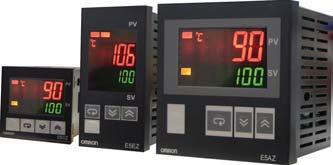
3 Digital Temperature Controller E5AZ New Generation of Digital Temperature Controller Depth of only 78mm. Various temperature inputs: thermocouple, platinum resistance thermometer, infrared temperature sensor, and analog inputs. Au-tuning and self-tuning are available. Au-tuning is possible even while self-tuning is being executed. Heating or heating/ cooling control is available. Event input allows multiple SP selection and run/sp function. Modular output cards. Time delay alarm function. Communication function. Conforms UL, CSA and IEC safety standards as well as CE marking. 96(W) x 96(H) x 78 (D) mm Model Number Structure Model Number Legend E5AZ Output type R: Relay Q: Voltage (for driving SSR) C: Current A: Others 2. Heater burnout alarm Blank: Not available H: Available 3. Option Blank: Not available 1: RS-232C 3: RS-485 B: 2 event input M: Option unit can be mounted Digital Temperature Controller E5AZ 1
4 Ordering Information E5AZ Standard Models Size Power supply voltage Number of alarm points VAC 1/4 DIN 96(W) x 96(H) x 78(D) mm Control outputs Heater burnout Model alarm Relay No E5AZ-R3 Voltage No E5AZ-Q3 (for driving SSR) Current No E5AZ-C3 Additional Control No E5AZ-A3 output Specifications Ratings Supply voltage Operating voltage range Power consumption Sensor input 124VAC 85% 11% of rated supply voltage 1W (1VA) Thermocouple: K, J, T, E, L, U, N, R, S, B Platinum resistance thermometer: Pt1, JPt1 Infrared temperature sensor: 1 7 C, 6 12 C, C, C Voltage input: 5mV SPST-NO, 25VAC, 5A (resistive load), electrical life: 1, operations 12 VDC +15%/-2% (PNP), max. load current: 4mA, with shortcircuit protection circuit 4 2mA DC, load: 6Ω max., resolution: approx. 2,6 Control output Relay output Voltage output Current output Alarm output SPST-NO, 25VAC, 2A (resistive load), electrical life: 1, operations Control method Setting method Indication method Other functions Ambient operating temperature Ambient operating humidity Srage temperature 2-PID control or / control Digital setting using front panel keys 7-segment digital display and single-lighting indicar Character height: PV:15.mm; SV: 9.5mm According Controller model -155 C (with no condensation or icing) 25%85% C (with no condensation or icing) 2 Digital Temperature Controller E5AZ
5 Input Ranges Platinum Resistance Thermometer Input Input type Pt1 JPt1 Temperature range C C C 5. C Setting number C Thermocouple Input Input type K J T E L U N R S B Temperature range C C C C -2 4 C C 6 C C -2 4 C C C 17 C 17 C Setting number C Shaded setting indicates the default setting ES1B Infrared Temperature Sensor Input Temperature range K1 7 C 9 C K6 12 C 12 C K C 165 C K14 26 C 26 C Setting number Analog Input Input type Temperature range 5mV Usable in the following ranges by scaling: or Setting number 21 Applicable standards by input type are as follows: K: GB/T R: GB/T J, L: GB/T S: GB/T T, U: GB/T B: GB/T E: GB/T JPt1, Pt1: GB/T N: GB/T Output Module Type Model Rating and performance Relay E53-AZR 25 VAC, 5A (resistive load), electrical life: 1, operations Voltage E53-AZQ 12 VDC, 4mA PNP type Current E53-AZC 4 2mA DC, load: 6Ω max, resolution: approx. 2,6 Communication Module Type Model Performance RS-232C E53-AZ1 Half-duplex: 12/24/48/96/192 bps ASC II RS-485 E53-AZ3 Full-duplex Other Module Type Model Rating and performance Event input E53-AZB : Max. 1KΩ : Min. 1KΩ Option board E53-AZM Expansion for E53-AZH and E53-AZ1 or E53-AZ3 or E53-AZB Heater burnout detection E53-AZH Using CT detect heater burnout Digital Temperature Controller E5AZ 3
6 Characteristics Indication accuracy Thermocouple: (±.5% of indicated value or ±1 C, whichever greater) ±1 digit max. (see note 1) Platinum resistance thermometer: (±.5% of indicated value or ±1 C, whichever greater) ±1 digit max. Analog input: ±.5% FS ±1 digit max. CT input: ±.5% FS ±1 digit max. Hysteresis C (in units of.1 C) Proportional band C (in units of.1 C) (P) Integral time (I) 3999 s (in units of 1 s) Derivative time (D) 3999 s (in units of 1 s) Control period 199s(inunitsof1s) Manual reset value.% 1.% (in units of.1%) Alarm setting range (decimal point position depends on input type) Input sampling 5ms period Insulation 2MΩ min. (at 5 VDC) resistance Dielectric strength 2VAC, 5 or 6 Hz for 1 min (between different charging terminal) Vibration resistance Hz, 2m/s for 1 min in X,Y, Z directions Shock resistance 2 1m/s,3timeseachin3axes,6directions Weight Approx. 31g / accessories approx. 1g Memory protection EEPROM (non-volatile memory) (number of writes: 1,) EMC Applicable standards Emission Enclosure: EN5511(GB/T ,2) Group1 class A Emission AC Mains: EN5511(GB/T ,2) Group1 class A (see note 2) Immunity ESD : IEC61-4-2(GB/T ) 4kV contact discharge (level 2) 8kV air discharge (level 3) Immunity RF-interference: IEC61-4-3(GB/T ): 1V/m, 8MHz-1Ghz (level 3) Immunity Conducted Disturbance: IEC61-4-6(GB/T ): 1V (.15-8MHz) (level 3) Immunity Burst: IEC61-4-5(GB/T ): 2kV power-line (level 3) 2kV I/O signal-line (level 4) UL611C-1, CSA C22.2 No.11.1 Conforms EN61326, EN611-1(IEC611-1) Note1: The indication of K thermocouples in the C range, and T and N thermocouples at a temperature of -1 C max., and U and L thermocouples at any temperature is ±2 C±1 digit maximum. The indication accuracy of the B thermocouples at a temperature of 4 C max. is not specified. The indication of the R and S thermocouples at a temperature of 2 C max. is ±3 C±1 digit maximum. Note2: For E5 Z- 3 3, in order fulfill EN61326 Class A standard, add a magnetism link (TDK: ZAT173-73) between K3SC and the controller. 4 Digital Temperature Controller E5AZ
7 Nomenclature Temperature Unit ALM1 Operation indicars ALM2 ALM3 HB PV No.1 display OUT1 OUT2 STOP CMW SV No.2 display Level key Up key E5AZ Down key Mode key Dimensions Note: All units are in millimeters unless otherwise indicated. Mounted Separately Group mounted (96 x no. of units -3.5) +1. ALM1 ALM2 ALM3 HB OUT1 OUT2 ST OP CMW PV SV min E5AZ Recommended panel thickness is 1 8 mm. ALM1 Group mounting is not possible in the vertical ALM2 ALM3 HB PV direction. (Maintain the specified mounting space 96 OUT1 OUT2 STOP CMW SV E5AZ 112 between Controllers when they are group mounted). When two or more E5AZs controllers are mounted, make sure that the surrounding temperature does not exceed the allowable operating temperature specified in the specifications. Digital Temperature Controller E5AZ 5
8 Wiring Terminals The voltage output (control output) is not electrically insulated from the internal circuits. When using a grounding thermocouple, do not connect any of the control output terminals the ground. If the control output terminals are connected the ground, errors will occur in the measured temperature values as a result of leakage current. Standard insulation is applied the power supply I/O sections. If reinforced insulation is required, connect the input and output terminals a device without any exposed current-carrying parts or a device with standard insulation suitable for maximum operation voltage of the power supply I/O section. AC1~24V Alarm output 25VAC 2A (resistive load) Input power supply AL3/OUT2 AL Event input RS232C 12 EV1 12 SD 13 EV2 13 RD CT 14 SG 16 RS B(+) 13 A(-) 14 Do not use Voltage output 12 VDC 4mV 6 AL1/HB 7 Current output DC 4 2mA OUT1 6Ω 8 A Relay output 25VSC 5A 9 (resistive load) - - B B 11 Analog input TC Pt Digital Temperature Controller E5AZ

9 Digital Temperature Controller E5EZ New Generation of Digital Temperature Controller Depth of only 78mm Various temperature inputs: thermocouple, platinum resistance thermometer, infrared temperature sensor, and analog inputs. Au-tuning and self-tuning are available. Au-tuning is possible even while self-tuning is being executed. Heating or heating/cooling control is available. Event input allows multiple SP selection and run/sp function. Modular output cards. Time delay alarm function Communication function Conforms UL, CSA and IEC safety standards as well as CE marking. 48(W) x 96(H) x 78 (D) mm Model Number Structure Model Number Legend E5EZ Output type R: Relay Q: Voltage (for driving SSR) C: Current A: Others 2. Heater burnout alarm Blank: Not available H: Available 3. Option Blank: Not available 1: RS-232C 3: RS-485 B: 2 event inputs M: Option unit can be mounted Digital Temperature Controller E5EZ 7
10 Ordering Information E5EZ Standard Models Size Power supply Number of Voltage alarm points 1/8 DIN 48(W) x 96(H) x 78(D) mm 1 24 VAC 3 Control outputs Heater burnout Model alarm Relay No E5EZ-R3 Voltage No E5EZ-Q3 (for driving SSR) Current No E5EZ-C3 Additional Control No E5EZ-A3 output Specifications Ratings Supply voltage Operating voltage range Power consumption Sensor input 1 24 VAC 85% 11% of rated supply voltage 1W (1VA) Thermocouple: K, J, T, E, L, U, N, R, S, B Platinum resistance thermometer: Pt1, JPt1 Infrared temperature sensor: 1 7 C, 6 12 C, C, C Voltage input: 5mV SPST-NO, 25VAC, 5A (resistive load), electrical life: 1, operations 12 VDC +15%/-2% (PNP), max. load current: 4mA, with shortcircuit protection circuit 4 2mA DC, load: 6Ω max., resolution: approx. 2,6 Control output Relay output Voltage output Current output Alarm output SPST-NO, 25VAC, 2A (resistive load), electrical life: 1, operations Control method Setting method Indication method Other functions Ambient operating temperature Ambient operating humidity Srage temperature 2-PID control or / control Digital setting using front panel keys 7-segment digital display and single-lighting indicar Character height: PV:14.mm; SV: 9.5mm According Controller model C (with no condensation or icing) 25%85% C (with no condensation or icing) 8 Digital Temperature Controller E5EZ
11 Input Ranges Platinum Resistance Thermometer Input Input type Pt1 JPt1 Temperature range C C C 5. C Setting number C Thermocouple Input Inputtype K J T E L U N R S B Temperature range C -2 5 C C C -2 4 C C 6 C C -2 4 C C C 17 C 17 C Setting number C Shaded setting indicates default setting ES1B Infrared Temperature Sensor Inputtype Temperature range K1 7 C 9 C K6 12 C 12 C K C 165 C K14 26 C 26 C Setting number Analog Input Inputtype Temperature range 5mV Usable in the following ranges by scaling: or Setting number 21 Applicable standards by input type are as follows: K: GB/T R: GB/T J, L: GB/T S: GB/T T, U: GB/T B: GB/T E: GB/T JPt1, Pt1: GB/T N: GB/T Output Module Type Model Rating and performance Relay E53-AZR 25 VAC, 5A (resistive load), electrical life: 1, operations Voltage E53-AZQ 12 VDC, 4mA PNP type Current E53-AZC 4 2mA DC, load: 6Ω max, resolution: approx. 2,6 Communication Module Type Model Performance RS-232C E53-AZ1 Half-duplex: 12/24/48/96/192 bps ASC II RS-485 E53-AZ3 Full-duplex Other Module Type Model Rating and performance Event input E53-AZB : Max. 1KΩ : Min. 1KΩ Option board E53-AZM Expansion for E53-AZH and E53-AZ1 or E53-AZ3 or E53-AZB Heater burnout detection E53-AZH Using CT detect heater burnout Digital Temperature Controller E5EZ 9
12 Characteristics Indication accuracy Thermocouple: (±.5% of indicated value or ±1 C, whichever greater) ±1 digit max. (see note 1) Platinum resistance thermometer: (±.5% of indicated value or ±1 C, whichever greater) ±1 digit max. Analog input: ±.5% FS ±1 digit max. CT input: ±.5% FS ±1 digit max. Hysteresis C (in units of.1 C) Proportional band C (in units of.1 C) (P) Integral time (I) 3999 s (in units of 1 s) Derivative time (D) 3999s(inunitsof1s) Control period 199s(inunitsof1s) Manual reset value.% 1.% (in units of.1%) Alarm setting range (decimal point position depends on input type) Input sampling 5ms period Insulation 2MΩ min. (at 5 VDC) resistance Dielectric strength 2VAC, 5 or 6 Hz for 1 min (between different charging terminal) Vibration resistance 1 55 Hz, 2m/s 2 for 1 min in X,Y, Z directions Shock resistance 1m/s 2, 3 times each in 3 axes, 6 directions Weight Approx. 26g / accessories approx. 1g Memory protection EEPROM (non-volatile memory) (number of writes: 1,) EMC Applicable standards Emission Enclosure: EN5511(GB/T ,2) Group1 class A Emission AC Mains: EN5511(GB/T ,2) Group1 class A (see note 2) Immunity ESD : IEC61-4-2(GB/T ) 4kV contact discharge (level 2) 8kV air discharge (level 3) Immunity RF-interference: IEC61-4-3(GB/T ): 1V/m, 8MHz-1Ghz (level 3) Immunity Conducted Disturbance: IEC61-4-6(GB/T ): 1V (.15-8MHz) (level 3) Immunity Burst: IEC61-4-5(GB/T ): 2kV power-line (level 3) 2kV I/O signal-line (level 4) UL611C-1, CSA C22.2 No.11.1 Conforms EN61326, EN611-1(IEC611-1) Note1: The indication of K thermocouples in the C range, and T and N thermocouples at a temperature of -1 C max., and U and L thermocouples at any temperature is ±2 C±1 digit maximum. The indication accuracy of the B thermocouples at a temperature of 4 C max. is not specified. The indication of the R and S thermocouples at a temperature of 2 C max. is ±3 C±1 digit maximum. Note2: For E5 Z- 3 3, in order fulfill EN61326 Class A standard, add a magnetism link (TDK: ZAT173-73) between K3SC and the controller. 1 Digital Temperature Controller E5EZ
13 Nomenclature Operation indicars ALM1 ALM2 ALM3 HB PV Temperature unit No. 1 display No. 2 display Operation indicars OUT1 OUT2 STOP CMW SV Mode key Up key Level key E5EZ Down key Dimensions Note: All units are in millimeters unless otherwise indicated. Panel Cuuts Mounted Separately Group mounted (48 x no. of units -2.5) min 45 + ALM1 ALM2 ALM3 HB PV Recommended panel thickness is 1 8 mm. Group mounting is not possible in the vertical 96 OUT1 OUT2 STOP CMW SV E5EZ 112 direction. (Maintain the specified mounting space between Controllers when they are group mounted). When two or more E5EZs controllers are mounted, make sure that the surrounding temperature does not exceed the allowable operating temperature specified in the specifications. Digital Temperature Controller E5EZ 11
14 Wiring Terminals The voltage output (control output) is not electrically insulated from the internal circuits. When using a grounding thermocouple, do not connect any of the control output terminals the ground. If the control output terminals are connected the ground, errors will occur in the measured temperature values as a result of leakage current. Standard insulation is applied the power supply I/O sections. If reinforced insulation is required, connect the input and output terminals a device without any exposed current-carrying parts or a device with standard insulation suitable for maximum operation voltage of the power supply I/O section. AC1~24V Alarm output 25VAC 2A (resistive load) Voltage output 12 VDC 4mV Current output DC 4 2mA 6Ω Relay output 25VSC 5A (resistive load) 1 Input power supply 2 3 AL3/OUT2 4 AL2 5 6 AL1/HB 7 OUT1 8 A B 1 B Analog input TC Pt Event input EV1 EV2 CT RS232C SD RD SG RS B(+) A(-) Do not use 12 Digital Temperature Controller E5EZ

15 Digital Temperature Controller E5CZ New Generation of Digital Temperature Controller Depth of only 78mm Various temperature inputs: thermocouple, platinum resistance thermometer, infrared temperature sensor, and analog inputs. Au-tuning and self-tuning are available. Au-tuning is possible even while self-tuning is being executed. Heating or heating/cooling control is available. Start/sp function Conforms UL, CSA and IEC safety standards as well as CE marking. 48(W) x 48(H) x 78 (D) mm Ordering Information E5CZ Standard Models Size Power supply voltage Number of alarm points 1/16 DIN 48(W) x 48(H) x 78(D) mm 1 24 VAC 2 Control outputs Relay Voltage (for driving SSR) Heater burnout alarm No No Model E5CZ-R2 E5CZ-Q3 E5CZ-Q2 Digital Temperature Controller E5CZ 13
16 Input Ranges Platinum Resistance Thermometer Input Input type Pt1 JPt1 Temperature range C C. 1. C C Setting number C Thermocouple Input Input type K J T E L U N R S B Temperature range C -2 5 C C C -2 4 C C 6 C C -2 4 C C C 17 C 17 C Setting number C Shaded setting indicates default setting ES1B Infrared Temperature Sensor Input type Temperature range K1 7 C 9 C K6 12 C 12 C K C 165 C K14 26 C 26 C Setting number Analog Input Input type 5mV Temperature range Usable in the following ranges by scaling: or Setting number 21 Applicable standards by input type are as follows: K: GB/T R: GB/T J, L: GB/T S: GB/T T, U: GB/T B: GB/T E: GB/T JPt1, Pt1: GB/T N: GB/T Digital Temperature Controller E5CZ
17 Specifications Ratings Supply voltage 1 24 VAC Operating voltage range 85% 11% of rated supply voltage Power consumption 7W (7VA) Sensor input Thermocouple: K, J, T, E, L, U, N, R, S, B Platinum resistance thermometer: Pt1, JPt1 Infrared temperature sensor: 1 7 C, 6 12 C, C, C Voltage input: 5mV Control output Relay output SPST-NO, 25VAC, 3A (resistive load), electrical life: 1, operations Voltage output 12 VDC +15%/-2% (PNP), max. load current: 21mA, with shortcircuit protection circuit Alarm output SPST-NO, 25VAC, 1A (resistive load), electrical life: 1, operations Control method 2-PID control or / control Setting method Digital setting using front panel keys Indication method 7-segment digital display and single-lighting indicar Character height: PV:1.mm; SV: 6.5mm Other functions According Controller model Ambient operating temperature C (with no condensation or icing) Ambient operating humidity 25% 85% Srage temperature C (with no condensation or icing) Digital Temperature Controller E5CZ 15
18 Characteristics Indication accuracy Thermocouple: (±.5% of indicated value or ±1 C, whichever greater) ±1 digit max. (see note) Platinum resistance thermometer: (±.5% of indicated value or ±1 C, whichever greater) ±1 digit max. Analog input: ±.5% FS ±1 digit max. Hysteresis C (in units of.1 C) Proportional band C (in units of.1 C) (P) Integral time (I) 3999 s (in units of 1 s) Derivative time (D) 3999s(inunitsof1s) Control period 199s(inunitsof1s) Manual reset value.% 1.% (in units of.1%) Alarm setting range (decimal point position depends on input type) Input sampling 5ms period Insulation 2MΩ min. (at 5 VDC) resistance Dielectric strength 2VAC, 5 or 6 Hz for 1 min (between different charging terminal) Vibration resistance 1 55 Hz, 2m/s 2 for 1 min in X,Y, Z directions Shock resistance 1m/s 2, 3 times each in 3 axes, 6 directions Weight Approx. 15g Memory protection EEPROM (non-volatile memory) (number of writes: 1,) EMC Emission Enclosure: EN5511(GB/T ,2) Group1 class A Emission AC Mains: EN5511(GB/T ,2) Group1 class A Immunity ESD : IEC61-4-2(GB/T ) 4kV contact discharge (level 2) 8kV air discharge (level 3) Immunity RF-interference: IEC61-4-3(GB/T ): 1V/m, 8MHz-1Ghz (level 3) Immunity Conducted Disturbance: IEC61-4-6(GB/T ): 1V (.15-8MHz) (level 3) Immunity Burst: IEC61-4-5(GB/T ): 2kV power-line (level 3) 2kV I/O signal-line (level 4) Applicable UL611C-1, CSA C22.2 No.11.1 standards Conforms EN61326, EN611-1(IEC611-1) Note: The indication of K thermocouples in the C range, T and N thermocouples at a temperature of -1 C max., and U and L thermocouples at any temperature is ±2 C±1 digit maximum. The indication accuracy of the B thermocouples at a temperature of 4 C max. is not specified. The indication of the R and S thermocouples at a temperature of 2 C max.is ±3 C±1 digit maximum. 16 Digital Temperature Controller E5CZ
19 ALM1 Nomenclature Temperature unit Operation indicars ALM1 ALM2 OUT1 OUT2 STOP PV SV No.1 display No.2 display Level key Up key E5CZ Mode key Down key Dimensions Note: All units are in millimeters unless otherwise indicated. Panel Cuuts Mounted Separately Group mounted (48 x no. of units -2.5) +1. ALM2 OUT1 STOP OUT2 P V S V 6min E 5CZ Recommended panel thickness is 1 8 mm. Group mounting is not possible in the vertical direction. (Maintain the specified mounting space ALM1 ALM2 OUT1 STOP OUT2 PV SV between Controllers when they are group mounted). E5CZ When two or more E5CZs controllers are mounted, make sure that the surrounding temperature does not exceed the allowable operating temperature specified in the specifications. Digital Temperature Controller E5CZ 17
20 Wiring Terminals The voltage output (control output) is not electrically insulated from the internal circuits. When using a grounding thermocouple, do not connect any of the control output terminals the ground. If the control output terminals are connected the ground, errors will occur in the measured temperature values as a result of leakage current. Standard insulation is applied the power supply I/O sections. If reinforced insulation is required, connect the input and output terminals a device without any exposed current-carrying parts or a device with standard insulation suitable for maximum operation voltage of the power supply I/O section. Voltage output DC12V 21mA Analog input Relay output 1 2 A B Pt B + + TC Input power supply Alarm output AL2/ OUT2 AL Digital Temperature Controller E5CZ
21 E5CZ Operation Indicars 1. ALM1 (alarm 1) Lights when alarm 1 output is ALM2 (alarm 2) Lights when alarm 2 output is. 2. OUT1, OUT2 (control output 1, control output 2) Lights when control output 1 and/or control output 2 (cool) are. However, if control output 1 is current output, OT1 will always be unlit. 3. STOP (sp) Lights when control of the E5CZ has been spped. During control, this indicar lights when an event or the run/sp function has become spped. Otherwise, this indicar is out. Temperature Unit The temperature unit is displayed when the display unit parameter is set a temperature. Indication is determined by the currently selected temperature unit parameter set value. When this parameter is set C, c is displayed, and when set F, f is displayed. ALM1 ALM2 OUT1 STOP OUT2 PV SV E5CZ No. 1 Display Displays the process value or parameter type. No. 2 Display Displays the set point, manipulated variable, or set value (setup) of the parameter. Up Key Each press of this key increases values displayed on the No.2 display. Holding down this key continuously increases values. Down Key Each press of this key decreases values displayed on the No.2 display. Holding down this key continuously decreases values. Level Key Press this key select the setup level. The setup level is selected in order operation level adjustment level, initial setting level communications setting level. Mode Key Press this key select parameters within each level. Level + Mode Keys This key combination sets the E5CZ the protect level. Digital Temperature Controller E5AZ 19
22 Nomenclature E5AZ Operation Indicars 1. ALM1 (alarm 1) Lights when alarm 1 output is. ALM2 (alarm 2) Lights when alarm 2 output is. ALM3 (alarm 3) Lights when alarm 3 output is. 2. HB (heater burnout alarm display) Lights when a heater burnout is detected. The heater burnout alarm remains by setting the heater burnout latch. T o reset, turn the power supply and then or set the heater burnout alarm value.a. 3. OUT1, OUT2 (control output 1, control output 2) Lights when control output 1 and/or control output 2 (cool) are. However, if control output 1 is current output, OUT1 will always be unlit. 4. STOP (sp) Lights when control of the E5AZ has been spped. During control, this indicar lights when an event or the run/sp function has become spped. Otherwise, this indicar is out. 5. CMW (communications writing control) Lights when communications writing is enabled and is out when it is disabled. Temperature Unit The temperature unit is displayed when the display unit parameter is set a temperature. Indication is determined by the currently selected temperature unit parameter set value. When this parameter is set C, c is displayed, and when set F, f is displayed. ALM1 ALM2 ALM3 HB OUT1 OUT2 STOP CMW PV SV No. 1 Display Displays the process value or parameter type. No. 2 Display Displays the set point, manipulated variable or set value (setup) of the parameter. Up Key Each press of this key increases values displayed on the No.2 display. Holding down this key continuously increases values. Down Key Each press of this key decreases values displayed on the No.2 display. Holding down this key continuously decreases values. E5AZ Level Key Press this key select the setup level. The setup level is selected in order operation level adjustment level, initial setting level communications setting level. Mode Key Press this key select parameters within each level. Level + Mode Keys This key combination sets the E5AZ the protect level. E5EZ Operation Indicars 1. ALM1 (alarm 1) Lights when alarm 1 output is. ALM2 (alarm 2) Lights when alarm 2 output is. ALM3 (alarm 3) Lights when alarm 3 output is. 2. HB (heater burnout alarm display) Lights when a heater burnout is detected. The heater burnout alarm remains by setting the heater burnout latch. T o reset, turn the power supply and then or set the heater burnout alarm value.a. 3. OUT1, OUT2 (control output 1, control output 2) Lights when control output 1 and/or control output 2 (cool) are. However, if control output 1 is current output, OUT1 will always be unlit. 4. STOP (sp) Lights when control of the E5EZ has been spped. During control, this indicar lights when an event or the run/sp function has become spped. Otherwise, this indicar is out. 5. CMW (communications writing control) Lights when communications writing is enabled and is out when it is disabled. Temperature Unit The temperature unit is displayed when the display unit parameter is set a temperature. Indication is determined by the currently selected temperature unit parameter set value. When this parameter is set C, c is displayed, and when set F, f is displayed. ALM1 ALM2 ALM3 HB OUT1 OUT2 STOP CMW PV SV No. 1 Display Displays the process value or parameter type. No. 2 Display Displays the set point, manipulated variable, or set value (setup) of the parameter. Up Key Each press of this key increases values displayed on the No.2 display. Holding down this key continuously increases values. Down Key Each press of this key decreases values displayed on the No.2 display. Holding down this key continuously decreases values. E5EZ Mode Key Press this key select parameters within each level. Level Key Press this key select the setup level. The setup level is selected in order operation level adjustment level, initial setting level com- munications setting level. Level + Mode Keys This key combination sets the E5EZ the protect level. 2 Digital Temperature Controller E5AZ/E5EZ/E5CZ
23 Operation Initial Setup On previous Controllers, sensor input type, alarm type and control period were set on DIP switches. These hardware settings are now set in parameters in setup menus. The and keys are used switch between setup menus, and the amount of time that you hold the keys down for determines which setup menu you move. This section describes two typical examples. 1. / Control Typical Application Examples Changing Parameters Typical Example Input type : 5 K thermocouple C Control method: / control Alarm type: 2 upper limit Alarm value 1: 2 C (For setting deviation) Set point: 1 C Change only the alarm value 1 and set point. The rest must be left as default settings. Setup procedure Power Power Operation level Process value/ set point Press key for at least three seconds. Control sps. indicates that there is a parameter. Keep on pressing the mode key until the desired parameter is selected. Se tinput specifications Initial setting level Check input type. 5 Input type5 Changing Set V alues Use the or keys change the set value displayed in the setup menu. Se tcontrol specifications Set alarm type Check that control is / control. Check alarm type. In / control Alarm 1 type Display E5AZ No. 1 display E5EZ No. 1 display No. 2 display Set the set point Operation level Press keys set set point 1 C. Press key for at least one second. Control starts. Process value/ set point1 E5CZ No. 2 display No. 1 display No. 2 display Check operation state Set alarm values Make sure that control is running. Press keys set alarm value 2 C. During run run During sp Alarm value 1 Start operation Start operation Digital Temperature Controller E5AZ/E5EZ/E5CZ 21
24 2. PID Control Using Au-tuning Changing Parameters Typical Example Input type: 9Tthermocouple-2 4 C Controlmethod: PID control S T(self-tuning): Calc ulate PID cons tants by AT(au-tuning). Alar mtype: 2upper limit Alarm value1: 3 C (For settingdeviation) Se tpoint: 15 C indicates that there is a parameter. Keep on pressing the mode key until the desired parameter is selected. Setup procedure Power Power Operation level Changing Set V alues Process value/ set point Display E5AZ Use the or keys change the set value displayed in the setup menu. Setinput specifications Initial setting level Press keys select input type. Press key for at least three seconds. Control sps. Input type 9 9 No. 1 display No. 2 display Set control specifications Press keys select PID control. In PID control E5EZ Self-tuning Press keys set ST. To cancel ST E5CZ No. 1 display No. 1 display No.2display PV/SP After AT execution. Check control period Check alarm type Check the control period. Check alarm type. Operation level Press Control period (heat) (unit: seconds) Alarm 1 type (upper-limit alarm) key for at least one second. When set, self-tuning operates. Recommended settings: 2 seconds for the relay output and 2 seconds for the SSR output. No. 2 display During AT execution. Set the set point Press keys set set point 15 C. Process value/ set point While AT is being executed, SP will flash. After AT execution. AT execution Adjustment level Execute AT (au-tuning). Press key for less than one second. To execute A T Set on for executing AT and for spping A T. During AT execution. Operation level Make sure that set point is 15 C. Press key for less than one second. Process value/ set point15 Set operation status Make sure that control is running. During run Set alarm values Press keys set alarm value 3 C. Alarm value 1 3 Start operation Start program execution 22 Digital Temperature Controller E5AZ/E5EZ/E5CZ
25 Specification Setting after Turning Power Outline of Operation Procedures Key Operation In the following d iagram, all the parameters are introduced in the display sequence. Some parameters may not be displayed depending on the protect settings and operation conditions. Power Operation level key 1 second min. key 3 seconds min. key Less than 1 second Adjustment level + key 1 second min. key Display flashes when key held down for more than 1 second. Control sps + key Display flashes when key pressed. + key 3 seconds min. Initial setting level key 1 second min. key Less than 1 second Input password set value 169 Advanced function setting level Communica - tions setting level Protect level Note: The time taken move the protect level can be adjusted by changing the ìmove protect level timeî setting. 1. Of these levels, the initial setting level, communications setting level, advanced function setting level and calibration level can be used only when control has spped. Note that control is spped when these four levels are selected. When switched back the operation level from one of these levels, control will start. Control in progress Control spped Level change Description of Each Level Operation Level This level is displayed when you turn the power. You can move the protect level, initial setting level and adjustment level from this level. Normally, select this level during operation. During operation, the process value, set point and manipulated variable can be monired, and the alarm value and upper- and lower-limit alarms can be monired and modified. Adjustment Level To select this level, press the key once for less than one second. This level is for entering set values and set values for control. This level contains parameters for setting the set values, AT (au-tuning), communications writing enable/disable, hysteresis, multi-sp, inputshift values, heater burnout alarm (HBA) and PID constants. You can move the p parameter of the operation level or initial setting level from here. Initial Setting Level To select this level, press the key for at least three seconds in the operation level. This level is for specifying the input type, selecting the control method, control period, setting direct/reverse action and alarm type. You can move the advanced function setting level or communications setting level from this initial setting level. To return the operation level, press the key for at least one second. To move the communications setting level, press the key once for less than one second. Protect Level To select this level, simultaneously press the and keys for at least 3 seconds. This level is prevent unwanted or accidental modification of parameters. Protected levels will not be displayed, and so the parameters in that level cannot be modified. Communications Setting Level To select this level, press the key once for less than one second in theinitial setting level. When the communications function is used, set the communications conditions in this level. Communicating with a personal computer (host computer) allows set points be read and written, and manipulated variables be monired. Advanced Function Setting Level To select this level, you must enter the password ( -169 ) in the initial setting level. You can move only the calibration level from this level. This level is for setting the aumatic return of display mode, MV limiter, event input assignment, standby sequence, alarm hysteresis, ST (self-tune) and move the user calibration level. Digital Temperature Controller E5AZ/E5EZ/E5CZ 23
26 Specification Setting after Turning Power Initial Setting Level This level is used for setting basic specifications of the Temperature Controller. Using this level, set the input type for selecting the input be connected such as the thermocouple or platinum resistance thermometer and set the range of set point and the alarm mode. Initial setting level in-t 5 Input type Power Operation level Adjustment level key Less than 1 second key 1 second min. key 3 seconds min. Initial setting level key 1 second min. Advanced function setting level Control sps. Communications key setting level Less than 1 second Input password set value ì-169î + key 1 second min. + key Display flashes when key pressed. Protect level + key 3 seconds min. The time taken move the protect level can be adjusted by changing the ìmove protect level timeî setting. in-h 1 in-l dp d-u c sl-h 13 sl-l -2 Scaling upper limit Scaling lower limit Decimal point Temperature unit Set point upper limit Set point lower limit For analog input (Input type: 16) - 5-mV setting Control in progress Control spped Level change The move from the operation level the initial setting level, press key for three seconds or more. The initial setting level is not displayed when initial/communications protection is set 2. This initial setting level can be used when initial setting/communications protection is set or 1. The scaling upper limit, scaling lower limit, and decimal point parameters are displayed when an analog voltage input is selected as the input type. cntl onof s-hc stnd st on cp 2 c-cp 2 PID / / Standard/heating and cooling ST (PID control) Control period (heat) Control period (cool) (PID control) (Heating/cooling setting) onof: / control pid: PID control stnd: Standard h-c: Heating/cooling on :Enabled : Disabled Set the pulse output cycle. orev or-r Direct/reverse operation or-r: Reverse operation or-d: Direct operation alt1 Alarm 1 type 2 alt2 2 Alarm 2 type Select the alarm mode. (Models with alarm function) amov Move advanced function setting level (When initial/communications protect is set "") To return the operation level, press the second * Not displayed as default setting. key for longer than one 24 Digital Temperature Controller E5AZ/E5EZ/E5CZ
27 Input Type When selecting the input type, follow the specifications listed in the following table. Input Temperature Range Platinum Resistance Thermometer Input Type Pt1 JPt ~85 ( C) ~5. ( C).~1. ( C) ~5. ( C) /-3~15 ( F) /-199.9~9. ( F) /~21. ( F) /-199.9~9. ( F) 4.~1. ( C) /.~21. ( F) Thermocouple Input Type K J ~13 ( C) -2.~5. ( C) -1~85 ( C) /-3~23 ( F) /.~9. ( F) /-1~15 ( F) 8-2.~4. ( C) /.~75. ( F) T ~4 ( C) 199.9~4. ( C) /-3~7 ( F) /199.9~ 7. ( F) E 1 ~6 ( C) /~11 ( F) L 11-1~85 ( C) /-1~15 ( F) U 12-2~4 ( C) /-3~7 ( F) ~4. ( C) /199.9~7. ( F) N 13-2~13 ( C) /-3~23 ( F) R 14 ~17 ( C) /~3 ( F) S 15 ~17 ( C) /~3 ( F) Non-contact Temperature Sensor ES1B B 1~7 C 6~12 C 115~165 C ~18 ( C) ~9 ( C) ~12 ( C) ~165 ( C) /3~32 ( F) /~19 ( F) /~24 ( F) /~32 ( F) 14~26 C 2 ~26 ( C) /~5 ( F) Analog input ~5mV 21 One of the following ranges depending on the results of scaling: , Note: The initial setting is: 5 : 2 85 C / F Digital Temperature Controller E5AZ/E5EZ/E5CZ 25
28 Alarm Types Select alarm types out of the 12 alarm types listed in the following table. Set Value aue Alarm Type Alarm Output Operation When X is positive When X is negative Alarm function Output 1 Upper- and lower-limit (deviation) (see note 1) 2 Upper-limit (deviation) 3 Lower-limit (deviation) (see note 2) 4 Upper- and lower-limit range L H (deviation) (see note 3) (see note 1) 5 Upper- and lower-limit with standby L H sequence (deviation) (see note 4) (see note 1) SP (see note 5) 6 Upper-limit with standby sequence X (deviation) 7 Lower-limit with standby sequence (deviation) 8 Absolute-value upper-limit 9 Absolute-value lower-limit 1 Absolute-value upper-limit with standby sequence 11 Absolute-value lower-limit with standby sequence Note 1: With set values 1, 4 and 5, the upper and lower limit values can be set independently for each alarm type, and are expressed as L and H. Following operations are for cases when an alarm set point is X or negative. Note 2: Set value: 1, Upper- and lower-limit alarm Case 1 Case 2 Case 3 (Always ) o o o o L X X SP SP SP SP SP SP X X X X H X Note 4: Set value: 5, Upper- and lower-limit with standby sequence Case 1 Case 2 Same as for the upper- and lower-limit alarm. However, when the upper-limit and lower-limit hysteresis overlaps: Always Example X SP X SP SP SP X X X X X X o o o o L H SP SP L H H<,L> H < L H>,L< H L > H SP L H LSP SP H L Note 3: Set value: 4, Upper- and lower-limit range Case 1 Case 2 Case 3 (Always ) L H SP SP L H H SP L H <, L > H >, L < H L SP H < L H > L SP H L H<,L> H<,L> H L H>,L< H L H<,L> H<,L> H L H>,L< H L Note 5: Set value: 5, Upper- and lower-limit with standby sequence alarm. Always when the upper-limit and lower-limit hysteresis overlaps. Set the alarm types for alarm 1 and alarm 2 independently in the initial setting level. The default setting is 2 (upper limit). Example: When the alarm is set at 11 C/ F or higher When an alarm type other than the absolute-value alarm is selected (For alarm types 1 7) The alarm value is set as a deviation from the set point. Alarm value 1 C/ F When the absolute-value alarm is selected (For alarm types 8 11) The alarm value is set as an absolute value from the alarm value of C/F. Alarm value 11 C/ F Set point 1 C/ F C/ F 26 Digital Temperature Controller E5AZ/E5EZ/E5CZ
29 Parameters Parameters related setting items for each level are marked in boxes in the flowcharts and brief descriptions are given as required. At the end of each setting item, press the mode key return the beginning of each level. Display Power + key Display flashes when key pressed. E5AZ Operation level Adjustment level key + key Less than 1 second 1 second + key min. key key Display flashes when key held 1 second 3 seconds down for more than 1 second. min. min. Control sps. Initial setting level key 1 second min. Advanced function setting level Communications setting level key Less than 1 second Password input set value key 3 seconds min. Protect level The time taken move the protect level can be adjusted by changing the ìmove protect level timeî setting. E5EZ E5CZ No. 1 display No. 1display No. 2 display No. 1 display No. 2 display Control in progress Control spped Level change No. 2 display Power Advanced Function Setting Level key 1 second min. Initial Setting Level key 1 second min. key 3 seconds min. Operation Level key Less than 1 second key Less than 1 second Adjustment Level Note: To select advanced function setting level, you must enter the password ( -169 ) in the initial setting level. Digital Temperature Controller E5AZ/E5EZ 27
30 Advanced Function Setting Level st-b 15. ST stable range For setting deviation init Parameter initialization alfa.65 2-PID parameter ev-m 1 No. of multi-sp used Select 2 or 4. ol-h 15. MV upper limit ev-1 none Event input assignment 1 Input setting: Multiple SP/RUN/STOP ol-l -5. MV lower limit Limitations MV ev-2 sp Event input assignment 2 inf. Input digital filter For setting time constant in seconds mspu Multi-SP uses on pvad Additional PV display Displayed first in the operation level sprt SP ramp set value Rate of change during ramp o-dp MV display rest a Standby sequence reset method Restarting condition after clearing nearby ret Aumatic return of display mode Aumatically reset the operation level when no key operation are performed al1n n-o Alarm1openinalarm / setting of a1lt Alarm 1 latch alh1.2 Alarm 1 hysteresis alarm output 1 a2lt Alarm 2 latch Alarm latches al2n n-o Alarm2openinalarm / setting of a3lt Alarm 3 latch alh2.2 Alarm 2 hysteresis alarm output 2 prlt Move protect level time al3n n-o Alarm3openinalarm / setting of sero Input error output alh3.2 Alarm 3 hysteresis alarm output 3 cjc on Cold junction compensation method hbu on Heater burnout detection rlrv MB command logic switching hbl Heater burnout Latch a1on Alarm 1 delay hbh.1 Heater burnout hysteresis a2on Alarm 2 delay a3on a1of a2of Alarm 3 delay Alarm 1 delay Alarm 2 delay Alarm / delay a3of Alarm 3 delay 28 Digital Temperature Controller E5AZ/E5EZ
31 Initial Setting Level Operation Level Input type 25 P rocess Value Scaling upper limit Scaling lower limit For analog input (Input type: 16) - 5-mV setting ct. r-s run PV/SP Set point during SP ramp Current value monir of HBA Multi-SP Run/Sp Select SP. Decimal point Number of displayed digits al-1 Alarm Set point value during 1 SP ramp Temperature unit c: C f: F al1h Heater current value monir Upper limit alarm value 1 Set either of Current these parameters value monirofhba Set point upper limit Limit the set point. al1l Run/sp Lower limit alarm value 1 :RUN :ST OP Set point lower limit al-2 Alarm value12 PID / Select the control system. Standard/heating and cooling onof : / control pid : PID control stnd : Standard h - c: Heating/cooling al2h al2l Upper-limit alarm value 2 alarm value 1 Lower-limit Lower alarm value limit alarm 1 value 2 Set either Set of either of these parameters. these parameters ST Self-tuning on : Enabled : Disabled al-3 Alarm value2 3 Control period (heat ing) OUT1 Control period (cool ing) OUT2 Set the pulse output cycle. al3h al3l Upper-limit alarm value 3 alarm value 2 Lower-limit Lower limit alarm value 3 alarm value 2 Set either Set either of of these these parameters parameters. Direct/reverse operation r : Reverse or- d : Direct Alarm 1 type Alarm 2 type Select the alarm mode. Alarm 3 type Move advanced function setting level Note: To select advanced function setting level, you must enter the password ( -169 ) in the initial setting level. Digital Temperature Controller E5AZ/E5EZ 29
32 Adjustment Level AT execute/cancel Communications writing Heater current value monir Heater burnout detection Set point Set point 1 Set point 2 Set point 3 Au-tuning on: Enabled : Disabled HBA function Set points used by multi-sp Protect Level Operation/adjustment protection Restricts displaying and modifying menus in operation and adjustment levels. Initial setting/communications protection Restricts display and modification of menus in the initial setting, operation level and adjustment levels. Setting change protection Protects changes setups by operating the front panel keys. Operation/Adjustment Protection The following table shows the relationship between set values and the range of protection. Level e Set value Operation PV levell PV/SP Other X X Adjustment level X X X When this parameter is set, parameters are not protected. Temperature input shift Upper-limit temperature input Lower-limit temperature input Proportional band Integral time Derivative time P I D 1-point shift 2-point shift (see note) Set either of these parameters PID settings Default setting: : Can be displayed and changed : Can be displayed X : Cannot be displayed and move other levels not possible Initial Setting/Communications Protection This protect level restricts movement the initial setting level, communications setting level and advanced function setting level. Set value Initial setting level Communications setting level Advanced function setting level 1 X 2 X X X Cooling coefficient Dead band Used in heating and cooling control Default setting: 1 : Move other levels possible X : Move other levels not possible Manual reset value Hysteresis (OUT 1) Hysteresis (OUT 2) Clear the of fset during stabilization of P or PD control. Set hysteresis. Setting Change Protection This protect level protects setup from being changed by operating the keys on the front panel. Set value Description Setup can be changed by key operation. Setup cannot be changed by key operation. (The protect level can be changed.) Note: The 2-point shift setting is only possible when the input type is a non-contact temperature sensor. Default setting: 3 Digital Temperature Controller E5AZ/E5EZ
33 Advanced Function Setting Level st-b 15. ST stable range For setting deviation init Parameter initialization alfa.65 2-PID parameter sprt SP ramp set value Rate of change during ramp ol-h 15. MV upper limit rest a Standby sequence reset Restarting condition after clearing nearby ol-l -5. inf. MV lower limit Limitations MV Input digital filter For setting time constant in seconds al1n n-o alh1.2 Alarm1openinalarm Alarm 1 hysteresis / setting of alarm output 1 pvad o-dp Additional PV display Displayed first in the operation level MV display al2n n-o alh2.2 Alarm 2 open in alarm Alarm 2 hysteresis / setting of alarm output 2 ret Aumatic return of display mode Aumatically reset the operation level when no key operation are performed a1lt a2lt prlt Alarm 1 latch Alarm 2 latch Move protect level time Alarm latches sero Input error output cjc on Cold junction compensation method rlrv MB command logic switching a1on Alarm 1 delay a2on a1of Alarm 2 delay Alarm 1 delay Alarm / delay a2of Alarm 2 delay Digital Temperature Controller E5CZ 31
34 Initial Setting Level Operation Level in-t Input type 25 Process Value in-h 1 Scaling upper limit sp-m Set point during SP ramp in-l Scaling lower limit For analog input (Input type: 16) - 5-mV setting r-s run Run/Sp dp Decimal point Number of displayed digits al-1 Alarm value 1 d-u Temperature unit c: C f: F al1h Upper limit alarm value 1 Set either of these parameters sl-h 13 sl-l -2 Set point upper limit Set point lower limit Limit the set point. al1l al-2 Lower limit alarm value 1 Alarm value 2 cntl onof s-hc stnd st PID / Select the control system. Standard/heating and cooling ST Self-tuning onof: / control pid : PID control stnd : Standard h-c: Heating/cooling on : Enabled : Disabled al2h al2l Upper limit alarm value 2 Lower limit alarm value 2 Set either of these parameters cp c-cp Control period (heat) OUT1 Control period (cool) OUT2 Set the pulse output cycle. orev or-r Direct/reverse operation or-r: Reverse or-d: Direct alt1 Alarm 1 type alt2 Alarm 2 type Select the alarm mode. amov Move advanced function setting levelp Note: To select advanced function settinglevel, you must enter the password ( -169 ) in the initial setting level. 32 Digital Temperature Controller E5CZ
35 Adjustment Level Protect Level at ins. in5h. in5l. p 8. i 233 d 4 c-5c 1. c-db. of-r 5 hy5 1. chys 1. AT execute/cancel Temperature input shift Au-tuning Upper-limit temperature input Lower-limit temperature input Proportional band P Integral time Derivative time Cooling coefficient Dead band Manual reset value Hysteresis (OUT1) I D Hysteresis (OUT2) 1-point shift 2-point shift PID settings Used in heating and cooling control Clear the set during stabilization of P or PD control Set hysteresis Operation/adjustment protection Restricts display ing and modif ying menus in opera tion and adjustment levels. Initial setting/communications protection Restricts display and modification of menus in the initial setting, operation level and adjustment levels. Setting change protection Protects changes setups by operating the front panel keys. Operation/Adjustment Protection The following table shows the relationship between set values and the range of protection. Level Set value Operation PV level PV/SP Other X X Adjustment level X X X When this parameter is set, parameters are not protected. Default setting: : Can be displayed and changed : Can be displayed X : Cannot be displayed and move other levels not possible Initial Setting/Communications Protection This protect level restricts movement the initial setting level, communications setting level and advanced function setting level. Set value Initial setting level Communications setting level Advanced function setting level 1 X 2 X X X Default setting: 1 : Move other levels possible X : Move other levels not possible Setting Change Protection This protect level protects setup from being changed by operating the keys on the front panel. Set value Description Setup can be changed by key operation. Setup cannot be changed by key operation. (The protect level can be changed.) Default setting: Digital Temperature Controller E5CZ 33
Temperature Controller
 E5AN Temperature Controller Temperature Controller OMRON Corporation Industrial Automation Company Industrial Devices and Components Division H.Q. Measuring Components Department Shiokoji Horikawa, Shimogyo-ku,
Communications None RS-232C RS-422* RS-485* BCD Transmission output*/** (4 to 20 ma) E5AX- E5AX- L(M)A02 L(M)A03
 E5AX- E5AX- L(M)A02 L(M)A03") Digital Controller A 96 x 96-mm (DIN) Digital Process Controller Optimum PID control with feed-forward control circuitry. High accuracy (+0.3% FS +1 digit max.). Replaceable Output Units. Models with communications
Digital Controller A 96 x 96-mm (DIN) Digital Process Controller Optimum PID control with feed-forward control circuitry. High accuracy (+0.3% FS +1 digit max.). Replaceable Output Units. Models with communications
TEMPERATURE CONTROLLER
 TEMPERATURE CONTROLLER E5CX(-H) DIN-sized super-compact (48 x 48-mm) Temperature Controller Featuring Advanced PID Control Advanced PID control with two degrees of freedom improves stability and response
Communications* None RS-232C RS-422 RS-485 BCD Transmission output** (4 to 20 ma)
") TEMPERATURE CONTROLLER DIN-sized (96 x 96-mm) Temperature Controller Featuring Advanced PID Control and Heater Burnout Detection Advanced PID control with two degrees of freedom to improve stability and
TEMPERATURE CONTROLLER DIN-sized (96 x 96-mm) Temperature Controller Featuring Advanced PID Control and Heater Burnout Detection Advanced PID control with two degrees of freedom to improve stability and
Series Temperature Controller Instruction Sheet
 Series Temperature Controller Instruction Sheet Thank you very much for purchasing DELTA A Series. Please read this instruction sheet before using your A series to ensure proper operation and please keep
Communications type RS-232C RS-422 RS-485 E5AJ-A2H02 E5EJ-A2H02
 Temperature Controller Fuzzy Self-tuning Temperature Controller with Advanced PID (2-PID) Control DIN-size: 6 x 6 mm (E5AJ), 2 x 2 mm (E5BJ), 4 x 4 mm (E5CJ), 4 x 6 mm (E5EJ) Fuzzy self-tuning and Auto-tuning
enproteko.com Specifications Ratings Item voltage to 24 VAC 5/6 Hz 24 VAC 5/6 Hz or 24 VDC Allowable voltage Characteristics 85% to 11% of power suppl
 enproteko.com Temperature Monitoring Relay K8AB-TH Compact and Slim Relay Ideal for Temperature Alarms and Monitoring Excessive increases can be prevented and abnormal s can be monitored. Temperature monitoring
Micro-controller X C C1 C2 AL1 AL2 AL3. Model: PXR4/5/9. Operation Manual SEL PXR. ECNO:406e
 C C1 C2 AL1 AL2 AL3 Micro-controller X Model: PXR4/5/9 PXR SEL Operation Manual ECNO:46e Table of Contents Part Names and Functions... 6 Operations... 7 2-1 Parameter list... 7 2-2 Basic operations...
E5CN Temperature Controller User s Manual
 E5CN Temperature Controller User s Manual Revised July 2003 Notice: OMRON products are manufactured for use according to proper procedures by a qualified operator and only for the purposes described in
Temperature Controllers
 Model TEC-4100 1/4 DIN Model TEC-4100 1/4 DIN Temperature Controller Ordering Code: Power Input BOX 1 4 = 90-250 VAC 5 = 11-26 VAC / VDC TEC-4100- Configurable for 4 Programmable Outputs and NEMA 4X/IP65
Universal controller for panel mounting Models CS6S, CS6H, CS6L
 Accessories Universal controller for panel mounting Models CS6S, CS6H, CS6L WIKA data sheet AC 85.08 Applications Plant and industrial furnace construction Process engineering Plastics technology and processing
TEMPERATURE CONTROL MODULE MODEL R3-TC2
 INSTRUCTION MANUAL R3-TC2 TEMPERATURE CONTROL MODULE MODEL R3-TC2 CONTENTS BEFORE USE... 2 POINTS OF CAUTION... 2 COMPONENT IDENTIFICATION... 2 INSTALLATION... 2 EXTERNAL DIMENSIONS unit: mm (inch)...
02/11/2015
 CTH 46 - CTD 43 / 46 CTD 46 Part number 89422108 CTH 46 Heating / cooling function Measurement and setpoint display CTD 43 Heating or cooling function Measurement display Measurement deviation display-setpoint
02/11/2015
 MIC48 With RS 485 link Part number 89422418 Heating and / or cooling function 2 independent alarms Load break detection 2 setpoint which can be selected remotely Manual / automatic power adjustment RS
Series Digital Controller Instruction Sheet
 216/3/11 Series Digital Controller Instruction Sheet Thank you very much for purchasing DELTA DTC Series Temperature Controller. Please read this instruction sheet before using your DTC series to ensure
Digital Heater Element Burnout Detector K8AC-H
 Digital Heater Element Burnout Detector K8AC-H A high-precision Heater Element Burnout Detector compatible with a wide-range of heater control methods. Push-in terminals reduce the workload. *1 Scaling
INSTRUCTION MANUAL Micro-computer based digital indicating controller
 INSTRUCTI MANUAL Micro-computer based digital indicating controller TP4A To prevent accidents arising from the misuse of this controller, please ensure the operator using it receives this manual. Caution
I/A Series 716C 1/16 DIN Temperature Controller
 Product Specifications I/A Series 716C 1/16 DIN Temperature Controller PSS 2C-1B5 A The Foxboro 716C is a powerful compact, 1/16 DIN, microprocessor-based temperature controller that offers a variety of
F4 Process Controller Installation and Operation Guide
 F4 Process Controller Installation and Operation Guide 1.Introduction 1.1.Highlight Features Space saving, only 55mm panel depth required Higher sampling rate (1mS) results in better control performance
E5AZ E5EZ. Digital Temperature Controller. Cat. No. H205-E1-01
 E5AZ E5EZ Digital Temperature ontroller User's Manual at. No. H25-E1-1 E5AZ/E5EZ Digital Temperature ontroller User s Manual Produced September 27 iv Preface The compact E5AZ/E5EZ Temperature ontroller
Instruction manual Micro-computer based digital indicating controller
 Instruction manual Micro-computer based digital indicating controller JCS-33A To prevent accidents arising from the misuse of this controller, please ensure the operator using it receives this manual.
SHIMADEN DIGITAL INDICATORS
 Shimaden, Temperature and Humidity Control Specialists C %RH MICROPROCESSOR-BASED SHIMADEN DIGITAL INDICATORS & NRTL /C approved BASIC FEATURES DIN Size 48 x 96 mm ±.25% High Accuracy Indication User-Selectable
E5CN/E5CN-U (48 x 48 mm)
") Basic-type Digital Temperature Controller /-U (48 x 48 mm) New 48 x 48-mm Basic Temperature Controller with Enhanced Functions and Performance. Improved Indication Accuracy and Preventive Maintenance Function.
Basic-type Digital Temperature Controller /-U (48 x 48 mm) New 48 x 48-mm Basic Temperature Controller with Enhanced Functions and Performance. Improved Indication Accuracy and Preventive Maintenance Function.
Non-contact voltage (for SSR drive): V DC DC current: 4 to 20mA DC Thermocouple: K, J, E Input. RTD: Pt100, JPt100
: V DC DC current: 4 to 20mA DC Thermocouple: K, J, E Input. RTD: Pt100, JPt100") INSTRUCTI MANUAL Micro-computer based Temperature Indicating Controller 1 GCS-00 No.GCS1E 200.11 To prevent accidents arising from the use of this controller, please ensure the operator receives this manual.
INSTRUCTI MANUAL Micro-computer based Temperature Indicating Controller 1 GCS-00 No.GCS1E 200.11 To prevent accidents arising from the use of this controller, please ensure the operator receives this manual.
GCS-300 No.GCS31E
 INSTRUCTI MANUAL Micro-computer based Temperature Indicating Controller GCS-00 No.GCS1E 200.0 To prevent accidents arising from the use of this controller, please ensure the operator receives this manual.
VERTEX VT10 SERIES PID OPERATION MANUAL MICROPROCESSOR BASED PID CONTROLLER
 1 VERTEX VT10 SERIES PID OPERATION MANUAL MICROPROCESSOR BASED PID CONTROLLER 1. INTRODUCTION This manual contains information for the installation and operation and tuning of our Vertex VT10 series self-tuning
Serie Rugghölzli 2 CH Busslingen. Tel. +41 (0) Fax +41 (0)
 Fax +41 (0)") Serie 5000 Tel. +1 (0)5 222 Fax +1 (0)5 222 12 PRODUCT INTRODUCTI PRODUCT INTRODUCTI 5 Series programmable temperature controller is FineTek's mid-range series of controllers. It uses a 12bit analog /
Serie 5000 Tel. +1 (0)5 222 Fax +1 (0)5 222 12 PRODUCT INTRODUCTI PRODUCT INTRODUCTI 5 Series programmable temperature controller is FineTek's mid-range series of controllers. It uses a 12bit analog /
UDC 700 Universal Digital Controllers and Indicator Specifications
 UDC 700 Universal Digital Controllers and Indicator Specifications 51-52-03-28 August 2002 Overview The UDC 700 is a 1/32 DIN (49 x 25 mm) controller which combines a high degree of technology and quality
Instruction manual for DIN rail mounting type indicating controller DCL-33A
 Instruction manual for DIN rail mounting type indicating controller DCL-33A To prevent accidents arising from the misuse of this controller, please ensure the operator using it receives this manual. Caution
Instruction manual Temperature Controller KT7
 Instruction manual Temperature Controller KT7 No. KT71E7 201.05 To prevent accidents arising from the misuse of this controller, please ensure the operator receives this manual. SAFETY PRECAUTIS Be sure
INSTRUCTION MANUAL FOR MICROCOMPUTER BASED TEMPERATURE INDICATING CONTROLLER JCD-13A, JCR-13A
 INSTRUCTION MANUAL FOR MICROCOMPUTER BASED TEMPERATURE INDICATING CONTROLLER JCD-13A, JCR-13A Preface Thank you for the purchase of our Microcomputer based Temperature Indicating Controllers JCD-13A or
Digital Panel Meter K3TL. Ordering Information. Low-cost, High-quality Digital Thermometer with Built-in Microcomputer. Accessories (Order Separately)
") Digital Panel Meter Low-cost, High-quality Digital Thermometer with Built-in Microcomputer Compact DIN-size (96 x 48 x 66 (W x H x D)) body. Mounting thickness of only 3.5 mm required. Highly visible display
Digital Panel Meter Low-cost, High-quality Digital Thermometer with Built-in Microcomputer Compact DIN-size (96 x 48 x 66 (W x H x D)) body. Mounting thickness of only 3.5 mm required. Highly visible display
ABB Instrumentation. Specifications. COMMANDER 150 Universal Process Indicator. the 1 /8 DIN indicator to match all your display requirements
 Specifications COMMANDER 150 Universal Process Indicator High visibility 6-digit LED display the clearest view of your process status 0.1% measurement accuracy precise indication of process measurement
ABB MEASUREMENT & ANALYTICS DATA SHEET. C50 1/16 DIN controller / alarm unit
 ABB MEASUREMENT & ANALYTICS DATA SHEET C50 1/16 DIN controller / alarm unit 2 C50 1/16 DI N CON TROLL ER / AL ARM U NIT DS/C 50-E N RE V. M Measurement made easy C50 the 1/16 DIN controller to suit your
CN4800 Series CONTROLLER
 CN4800 Series CONTROLLER Operator's Manual PV SV OUT1 OUT2 ALM1 ALM2 SEL M1791/0502 Contents I. PREPARING THE OPERATION... 4 1. THE BASIC INSTALLATION PROCEDURE... 5 2. CHECK OF SPECIFICATIONS... 6 2.1
AH3000 SERIES 180MM CHART PEN TYPE HYBRID RECORDER
 AH3000 SERIES 180MM CHART PEN TYPE HYBRID RECORDER MODEL AH3 7 P - - A AH3000 series conforming to CE, UL and CSA are 180mm pen type hybrid recorders with a simultaneous display of multi-channel data,
Process & TeMPerATUre UniversAl input DigiTAl MeTers
 Process & TeMPerATUre UniversAl input DigiTAl MeTers nova PD56 series Thermocouple, rtd, & Process inputs Universal Power supply 1-24 va c Up to 3 Alarm relays retransmitting 4-2 ma output input Max/Min
DCL-33A No.DCL31E To prevent accidents arising from the misuse of this controller, please ensure the operator receives this manual.
 INSTRUCTI MANUAL DIN RAIL MOUNTING TYPE INDICATING CTROLLER DCL-A No.DCL1E5 200.08 To prevent accidents arising from the misuse of this controller, please ensure the operator receives this manual. SAFETY
MICRO CONTROLLER S Z SERIES
 Instruction Manual MICRO CONTROLLER S Z SERIES TYPE: PYW 4 5 7 9 Fuji Electric Co.,Ltd. INP-TN1PYWf-E INTRODUCTION You are now the owner of Fuji's digital Temperature Controller. Before using, be sure
PROCESS & TEMPERATURE UNIVERSAL INPUT DIGITAL METERS
 PROCESS & TEMPERATURE UNIVERSAL INPUT DIGITAL METERS NOVA PD56 Series Thermocouple, RTD, & Process Inputs Universal Power Supply 1-24 VAC Up to 3 Alarm Relays Retransmitting 4-2 ma Output Input Max/Min
INSTRUCTION MANUAL FOR MICROCOMPUTER BASED TEMPERATURE INDICATING CONTROLLER GCD-200, GCR-200
 INSTRUCTION MANUAL FOR MICROCOMPUTER BASED TEMPERATURE INDICATING CONTROLLER GCD-200, GCR-200 PV PV AT AT OUT1 OUT2/HB A1 A2 OUT1 OUT2/HB A1 A2 MODE OUT MODE OUT GCD GCR Preface Thank you for the purchase
Example of Applications and Parameter Functions
 PX-series digital temperature controller Example of Applications and Functions ECNO:1158 I. Example of Applications 1 Controlling both heating and cooling with a single controller Only one controller is
UDC1000 and UDC1500 MICRO-PRO SERIES UNIVERSAL DIGITAL CONTROLLERS
 UDC1000 and UDC1500 MICRO-PRO SERIES UNIVERSAL DIGITAL CONTROLLERS EN0I-6041 4/01 PRODUCT SPECIFICATION SHEET OVERVIEW The UDC1000 and UDC1500 are microprocessor-based 1/16 DIN and 1/8 DIN controllers
MODEL: 47LT. Digital Panel Meters 47 Series. [3] DISPLAY COLOR R: Red YR: Orange G: Green BG: Bluegreen B: Blue W: White. [4] POWER INPUT AC Power
![MODEL: 47LT. Digital Panel Meters 47 Series. [3] DISPLAY COLOR R: Red YR: Orange G: Green BG: Bluegreen B: Blue W: White. [4] POWER INPUT AC Power](/thumbs/96/127040517.jpg "MODEL: 47LT. Digital Panel Meters 47 Series. [3] DISPLAY COLOR R: Red YR: Orange G: Green BG: Bluegreen B: Blue W: White. [4] POWER INPUT AC Power") Digital Panel Meters 47 Series THERMOCOUPLE INPUT DIGITAL PANEL METER (4-digit, LED display type) Functions & Features 4-digit thermocouple input digital panel meter 1/8 DIN size Moving average function
Digital Panel Meters 47 Series THERMOCOUPLE INPUT DIGITAL PANEL METER (4-digit, LED display type) Functions & Features 4-digit thermocouple input digital panel meter 1/8 DIN size Moving average function
AL3000 SERIES 100MM CHART MULTI-POINT TYPE HYBRID RECORDER
 AL3000 SERIES 100MM CHART MULTI-POINT TYPE HYBRID RECORDER MODEL AL3 7 5 - AL3000 series conforming to CE, UL and CSA are 100mm multi-point type hybrid recorders with a simultaneous display of multi-channel
SA100. General Description. Features. Temperature Controller SA100. Corresponding to Various Applications. Simple Mounting on DIN Rail
 Temperature Controller General Description The is a socket mounting type temperature controller and is available for mounting inside the panel or by easily mounting on DI rail. The has features such as
ARTIFICIAL INTELLIGENCE TEMPERATURE CONTROLLER
 ARTIFICIAL INTELLIGENCE TEMPERATURE CONTROLLER AI-208 (V7.6) User Manual I. Model Code Symbol The type of AI-208 is made up of 4 parts: AI-208 A G L2 Part 1 (Series) Part 2 (Size) Part 3 (Oupt) Part 4
Nov 08 PRODUCT SPECIFICATION SHEET
 Honeywell UDC1200 and UDC1700 MICRO-PRO SERIES UNIVERSAL DIGITAL CONTROLLERS 51-52-03-35 Nov 08 PRODUCT SPECIFICATION SHEET OVERVIEW The UDC1200 & UDC1700 are microprocessor-based 1/16 DIN and 1/8 DIN
Warning Caution INSTRUCTION MANUAL DIN RAIL MOUNTING TYPE INDICATING CONTROLLER
 INSTRUCTI MANUAL DIN RAIL MOUNTING TYPE INDICATING CTROLLER 1 DCL-A DC No.DCLDCE1 2007.01 Thank you for purchasing our DIN rail mounting type indicating controller DCL-A DC. This manual contains instructions
Specification , July 2015
 Technical Information PrecisionLine Controllers EDC21 / EDC22 / EDC23 EASYSET DIGITAL CONTROLLERS Specification 51-52-3-48, July 215 Introduction The EDC21, EDC22 and EDC23 controllers provide precise
INSTRUCTION MANUAL FOR MICROCOMPUTER BASED TEMPERATURE INDICATING CONTROLLER FCS-23A
 INSTRUCTION MANUAL FOR MICROCOMPUTER BASED TEMPERATURE INDICATING CONTROLLER Thank you for your purchase of our Microcomputer based Temperature Indicating Controller. This manual contains instructions
UDC100 Universal Digital Controller Specifications
 UDC100 Universal Digital Controller Specifications 51-52-03-29 November 1999 Overview The UDC100 Universal Digital Controller is a microprocessor-based 1/4 DIN low cost temperature controller. It combines
Series Temperature Controller Instruction Sheet
 Series Temperature Controller Instruction Sheet Thank you very much for choosing Delta DTE series temperature controller. Please read this instruction sheet carefully before using your DTE to ensure proper
Table of Contents SECTION PAGE
 Table of Contents SECTION PAGE SECTION 1 INTRODUCTION................... 1.1 Description.............................. 1.2 Features................................ 1.3 Models.................................
4TEMPERATURE CONTROLLER
 Universal Input Output and High Accuracy 0.5 class 250ms TEMPERATURE ONTROLLER RAMP function PID Auto-tuning Universal input /, Reverse/Direct action selectable Remote/Local input selectable Model and
DIN RAIL MOUNTED INDICATING CONTOLLER DCL-33A INSTRUCTION MANUAL
 DIN RAIL MOUNTED INDICATING CONTOLLER DCL-A INSTRUCTION MANUAL Preface Thank you for purchasing our DIN rail mounted indicating controller DCL-A. This manual contains instructions for the mounting, functions,
Interchangeable thermistor (THE types) Output Contact E5CS-R1KJX-F E5CS-R1PX-F E5CS-R1GX-F Voltage E5CS-Q1KJX-F E5CS-Q1PX-F E5CS-Q1GX-F
 Output Contact E5CS-R1KJX-F E5CS-R1PX-F E5CS-R1GX-F Voltage E5CS-Q1KJX-F E5CS-Q1PX-F E5CS-Q1GX-F") Temperature Controller 1/16 DIN Sized Controller Offers Selectable Control, Alarm Modes Accurate to ±0.5% of full scale Multiple temperature scale ranges allow flexibility to match application Field-selectable
Temperature Controller 1/16 DIN Sized Controller Offers Selectable Control, Alarm Modes Accurate to ±0.5% of full scale Multiple temperature scale ranges allow flexibility to match application Field-selectable
Tempco Part Number PCT30006 Temperature Control Enclosure with Relay Output for Tote Tank Heating Applications
 Instruction Manual Tempco Part Number PCT30006 Temperature Control Enclosure with Relay Output for Tote Tank Heating Applications Manual PCT30006, Revision 9/20/2016 The PCT30006 control enclosure incorporates
Cat. No. H113-E1-03B E5ZN. Temperature Controller OPERATION MANUAL
 Cat. No. H113-E1-03B E5ZN Temperature Controller OPERATION MANUAL E5ZN Temperature Controller Operation Manual Revised November 2005 Notice: OMRON products are manufactured for use according to proper
TAIE. Features. FY600 (96mm X 48mm) Application:Control temperature,humidity, FY Series Digital PID Controller
 Application:Control temperature,humidity, FY Series Digital PID Controller") TAIE FY Series Digital PID Controller FY600 (96mm X 48mm) Application:Control temperature,humidity, FY series controllers are microprocessor based controllers. Which have been Designed with high accuracy
TAIE FY Series Digital PID Controller FY600 (96mm X 48mm) Application:Control temperature,humidity, FY series controllers are microprocessor based controllers. Which have been Designed with high accuracy
INSTRUCTION MANUAL FOR TOUCH PANEL MONITORING UNIT CMT-220-K
 INSTRUCTION MANUAL FOR TOUCH PANEL MONITORING UNIT PREFACE Thank you for your purchase of our Touch panel monitoring unit. This manual contains instructions for the mounting, functions, operations and
Tempco PCT-3000 Series Temperature Control Console with Relay Output for Heating or Cooling Applications
 Instruction Manual Tempco PCT-3000 Series Temperature Control Console with Relay Output for Heating or Cooling Applications Manual PCT-3000 Revision 9/2014 The PCT-3000 series control console incorporates
Infrared port USB. Control Output 2. (built-in) SSR outputs
 SSR outputs") Advanced Digital Temperature Controller / (96 x 96 mm and 48 x 96 mm) CSM DS_E A New High-performance Controller: High Resolution, High Speed, and High Input Accuracy. Logic Operations and Preventive Maintenance
Advanced Digital Temperature Controller / (96 x 96 mm and 48 x 96 mm) CSM DS_E A New High-performance Controller: High Resolution, High Speed, and High Input Accuracy. Logic Operations and Preventive Maintenance
7EF/7HF/7EC/7ES Temperature Controllers
 7EF/7HF/7E/7ES Temperature ontrollers Dual 4 Digit LED Display Universal Input (6 T/, RTD, mv, V, ma) Autotuning NEMA 4X 100 to 240 Vac Switching Power Supply Algorithms for Heat or Heat/ool ontrol 2 Independent
Safety Information. Functional Description. Operation. DANGER Do not touch or contact the input/output terminals because it may cause electric shock.
 Temperature Controller KXN Series INSTRUCTION MANUAL Thank you for purchasing HANYOUNG NUX CO,.Ltd. Product. Please check whether the prouduct you purchased is the exactly same as you ordered. Before using
E5EZ-PRR. Position Proportional Controller. User s Manual. Cat. No. H200-E1-01
 E5EZ-PRR Position Proportional Controller User s Manual Cat. No. H2-E1-1 Introduction E5EZ-PRR Temperature Controller Features: Thank you for choosing the OMRON E5EZ-PRR. This user manual describes E5EZ-PRR
JIR-301-M No.JIR31E To prevent accidents arising from the misuse of this instrument, please ensure the operator receives this manual.
 INSTRUCTION MANUAL MICRO-COMPUTER BASED DIGITAL INDICATOR JIR-31-M No.JIR31E3 24.7 To prevent accidents arising from the misuse of this instrument, please ensure the operator receives this manual. SAFETY
THE SUPERDRYER CACTUS 5 CACTUS 10 CACTUS 15 CACTUS 25 CACTUS 50 INSTALLATION AND OPERATING INSTRUCTIONS PATENTED
 THE SUPERDRYER PATENTED CACTUS 5 CACTUS 10 CACTUS 15 CACTUS 25 CACTUS 50 INSTALLATION AND OPERATING INSTRUCTIONS CACTUS SUPERDRYER OPERATION MANUAL INTRODUCTION Your Cactus Superdryer has been designed,
MICRO CONTROLLER E Z SERIES
 Instruction Manual MICRO CONTROLLER E Z SERIES TYPE: PYZ 4 5 7 9 Fuji Electric Co.,Ltd. INP-TN2PYZDe-E INTRODUCTION You are now the owner of Fuji's Digital Temperature Controller. Before using, be sure
Model 96VTR ¼ DIN Process Controller
 99 Washington Street Melrose, MA 02176 Phone 781-665-1400 Toll Free 1-800-517-8431 Visit us at www.testequipmentdepot.com Back to the Extech 96VTR Product Info Page INSTRUCTION MANUAL Model 96VTR ¼ DIN
TAIE. Features. FY900 (96mm X 96mm) Application:Control temperature,humidity, FY Series Digital PID Controller
 Application:Control temperature,humidity, FY Series Digital PID Controller") TAIE FY Series Digital PID Controller FY900 (96mm X 96mm) Application:Control temperature,humidity, FY series controllers are microprocessor based controllers. Which have been Designed with high accuracy
TAIE FY Series Digital PID Controller FY900 (96mm X 96mm) Application:Control temperature,humidity, FY series controllers are microprocessor based controllers. Which have been Designed with high accuracy
The display section precisely shows the current status to onsite operators. Displayable Status Easily Recognize the PV Easily See
 NEW»»» Changes in the color of the PV show the current status. You can select between different patterns for color combinations. If a certain status occurs, the status will be displayed alternating with
DIGITAL INDICATING CONTROLLER FCS-23A INSTRUCTION MANUAL
 DIGITAL INDICATING CONTROLLER FCS-23A INSTRUCTION MANUAL Preface Thank you for purchasing our Digital indicating controller FCS-23A. This manual contains instructions for the mounting, functions, operations
SA200. General Description. Features. Temperature Controller SA200. Self-Tuning Algorithm. Close Vertical or Horizontal Mounting
 Temperature Controller General Description The is a high performance 3 nd DI controller that has been specifically designed for applications where panel space is critical. Though small in size, this controller
Bulletin 900-TC. Bulletin 900 TC Temperature/Process Controllers. Certifications. Bulletin 900-TC8 Controller Models
 Bulletin 900-TC Bulletin 900 TC Temperature/Process Controllers Single-loop, high value, ON/OFF, or analog output controllers 1/8 DIN (Bulletin 900-TC8), 1/16 DIN (Bulletin ), and 1/32 DIN (Bulletin )
SR70 (SR ) Series Digital controller Instruction Manual
 Series Digital controller Instruction Manual") SR70 (SR71 72 73 74) Series Digital controller Instruction Manual Thank you for purchasing the Shimaden SR70 Series. Please check that the delivered product is the correct item you ordered. Please do not
SR70 (SR71 72 73 74) Series Digital controller Instruction Manual Thank you for purchasing the Shimaden SR70 Series. Please check that the delivered product is the correct item you ordered. Please do not
370, boulevard de Balmont LYON Tel Fax Web:
 AUTOMATISME Régulateurs de température delta DELTA développe, dessine, fabrique des composants et des équipements électronique pour les plus importants constructeurs internationaux. Fort de ses 30.000
TC515 and TC600 Installation Manual. a Winters company
 THERMOLINE TEMPERATURE CONTROLLERS TC515 and TC600 Installation Manual a Winters company Guarantee 12 months Congratulations on the purchase of this new product. Special care with the design, workmanship
High Resolution Temperature Controller REX-F9000. Instruction Manual IM9000F01-E5 RKC INSTRUMENT INC.
 High Resolution Temperature Controller REX-F9000 Instruction Manual RKC INSTRUMENT INC. IM9000F01-E5 All Rights Reserved, Copyright 1999, RKC INSTRUMENT INC. Thank you for purchasing this RKC product.
99 Washington Street Melrose, MA Phone Toll Free Visit us at
 99 Washington Street Melrose, MA 02176 Phone 781-665-1400 Toll Free 1-800-517-8431 Visit us at www.testequipmentdepot.com Back to the Extech 48VTR Product Info Page Instruction Manual English / Español
E5AN/E5EN (96 x 96 mm and 48 x 96 mm)
") Basic-type Digital Temperature Controller E5AN/E5EN (96 x 96 mm and 48 x 96 mm) CSM_E5AN_E5EN_DS_E_4_1 New 96 x 96-mm and 48 x 96-mm Basic Temperature Controllers with Enhanced Functions and Performance.
Basic-type Digital Temperature Controller E5AN/E5EN (96 x 96 mm and 48 x 96 mm) CSM_E5AN_E5EN_DS_E_4_1 New 96 x 96-mm and 48 x 96-mm Basic Temperature Controllers with Enhanced Functions and Performance.
VT4810 SINGLE / DUAL ZONE CONTROLLER INSTALLATION MANUAL
 Thermocouple Type BS4937 (IEC584-3): Outer / + / - BS1843 (Old UK Standard) Outer / + / - US Outer / + / - J : Iron / Copper-Nickel Black / Black / White Black / Yellow / Blue Black / White / Red VT4810
JIR-301-M No.JIR31E To prevent accidents arising from the misuse of this instrument, please ensure the operator receives this manual.
 INSTRUCTI MANUAL MICRO-COMPUTER BASED DIGITAL INDICATOR JIR-31-M No.JIR31E6 28.8 To prevent accidents arising from the misuse of this instrument, please ensure the operator receives this manual. SAFETY
Programmable Temperature Controller (Digital Controller)
") Programmable Temperature Controller (Digital Controller) E5AN-HT/ (96 x 96 mm and 48 x 96 mm) _ E Programmable Controllers Join the Series! Program up to 56 segments and take advantage of the high cost
Programmable Temperature Controller (Digital Controller) E5AN-HT/ (96 x 96 mm and 48 x 96 mm) _ E Programmable Controllers Join the Series! Program up to 56 segments and take advantage of the high cost
eed quality electronic design USER s MANUAL
 eed quality electronic design www.dem-it.com eed www.qeed.it info@qeed.it ANALOG SIGNAL DISPLAY Q-DISP-T USER s MANUAL The displays Q-DISP-T, prepared for mounting on the back panel, 96x48mm, will allow
1. Model ACS 1 3 A / A, Series name: ACS-13A- /A (W48 x H48 x D62mm) Control action 3 PID A1 A Alarm type can be selected by keypad.
 Control action 3 PID A1 A Alarm type can be selected by keypad.") INSTRUCTI MANUAL (EXCERPT) Digital Indicating Controller ACS-13A- /A (For Use with the Infrared Temperature Sensor RD-500) No.ACS11AE1 2011.07 The digital indicating controller ACS-13A /A is an exclusive
INSTRUCTI MANUAL (EXCERPT) Digital Indicating Controller ACS-13A- /A (For Use with the Infrared Temperature Sensor RD-500) No.ACS11AE1 2011.07 The digital indicating controller ACS-13A /A is an exclusive
Terwin Instruments Ltd.
 Terwin Instruments Ltd. Temperature PID Controllers MC-x8 OPERATIONAL MANUAL MC 8 / MC 8 / MC 8 MC 8 / MC 88 ( Display unit & Indication lamps ~ =Measured value display =Set value dispaly Alarm output
E5CN/E5CN-U (48 x 48 mm)
") Basic-type Digital Temperature Controller /-U (48 x 48 mm) CSM -U_DS_E_5_1 New 48 x 48-mm Basic Temperature Controller with Enhanced Functions and Performance. Improved Indication Accuracy and Preventive
Basic-type Digital Temperature Controller /-U (48 x 48 mm) CSM -U_DS_E_5_1 New 48 x 48-mm Basic Temperature Controller with Enhanced Functions and Performance. Improved Indication Accuracy and Preventive
DIGITAL INDICATOR DI25
 DIGITAL INDICATOR DI25 Operating instructions Preface Thank you for purchasing our digital indicator DI25. This manual contains instructions for the mounting, functions, operations and notes when operating
CONTENTS. Micro-controller X Model : PXR3. Instruction Manual
 Instruction Manual Micro-controller X Model : PXR3 INP-TN1PXR3c-E Head Office 11-2, Osaki 1-chome, Shinagawa-ku, Tokyo, 141-32 Japan Sales Div. International Sales Dept. No.1, Fuji-machi, Hino-city, Tokyo,
General Specifications
 General Specifications GS J0H-0E Model MVHK Digital Limit Alarm (DC Type) with Active Color PV Display General This plug-in type Digital Limit Alarm for DC input receives DC current or DC voltage signal.
E5CN/E5CN-U (48 x 48 mm)
") Basic-type Digital Temperature Controller /-U (48 x 48 mm) CSM -U_DS_E_5_7 New 48 x 48-mm Basic Temperature Controller with Enhanced Functions and Performance. Improved Indication Accuracy and Preventive
Basic-type Digital Temperature Controller /-U (48 x 48 mm) CSM -U_DS_E_5_7 New 48 x 48-mm Basic Temperature Controller with Enhanced Functions and Performance. Improved Indication Accuracy and Preventive
+ A B V B NO NC V COM PV PV
 + - A + B B - V + - NO NC COM + - + - V + - PV PV Ramp Soak 100 70 50 30 3 5 3 8 5 3 Minute Steam Heating Sensor Cooling Water PID Hotplate Specifications Input power supply AC 100 to 240V, 50/60Hz, DC
AutomationDirect PM24. Microprocessor - Based Process/Temperature Limit Controller. Operator s Manual. Technical Support.
 AutomationDirect 1/16 DIN Series Technical Support We strive to make our manuals the best in the industry. We rely on your feedback to let us know if we are reaching our goal. If you cannot find the solution
Table of Contents SECTION PAGE SECTION 1 INTRODUCTION Description Features Models... SECTION 2 RS-232 COMMUNICATIONS...
 SECTION Table of Contents SECTION 1 INTRODUCTION...................... 1.1 Description............................... 1.2 Features................................. 1.3 Models..................................
STT 3000 Series STT250 Smart Temperature Transmitters Specifications Models STT25T EN0l-6091 February 2009
 STT 3000 Series STT250 Smart Temperature Transmitters Specifications Models STT25T EN0l-6091 February 2009 Introduction Honeywell s STT 3000 family of microprocessor based transmitters covers the full
INSTRUCTIONS FOR THE 8500 SERIES MICROPROCESSOR BASED TEMPERATURE CONTROL
 INSTRUCTIONS FOR THE 8500 SERIES MICROPROCESSOR BASED TEMPERATURE CONTROL December, 1998 Page 1 949-1275-1 TABLE OF CONTENTS MODEL IDENTIFICATION... 4 INSTALLATION... 4 WIRING... 5 FRONT PANEL KEY FUNCTIONS...
OVEN INDUSTRIES, INC.
 OVEN INDUSTRIES, INC. OPERATING MANUAL Model 5C7-252 TEMPERATURE CONTROLLER With PLC Inputs Introduction Thank you for purchasing our controller. The Model 5C7-252 is an exceptionally versatile unit and
DS 96/48 P. Digital indicator. Short manual 41/33-89 EN Rev. 00 DIM
 DS 96/48 P Digital indicator Short manual 41/33-89 EN Rev. 00 A1 A2 DIM E 1 Safety instructions Correct and safe operation of the apparatus calls for expert installation and meticulous maintenance. This
CN-6000 Series. Features. Ordering information CN C1. Part descriptions. 5 ( key: Used to enter parameter set mode, move to parameters,
 CN-6000 eries Features Multi-input CN-610 : Thermocouple 12 types, RTD 5 types, Analog (mv, V, ma) 6 types CN-640 : 0 to 50.00kHz Improves visibility with negative LCD : 12 segment, 3 colors (selectable