EXPERTS IN WATER CHEMISTRY SINCE Iron Analyzer User Manual. Revision 3.04
|
|
|
- Justin Conley
- 5 years ago
- Views:
Transcription

1 EXPERTS IN WATER CHEMISTRY SINCE 1903 User Manual Revision 3.04
2 Waltron Customer Commitment WALTRON CUSTOMER COMMITMENT This instruction manual is a technical guide to aid the customer in the set-up, operation, and maintenance of their new Waltron measuring system. Waltron provides continuous product improvement and reserves the right to make any modifications to the information contained herein without notice. Copyright Waltron Bull & Roberts, LLC, 2016 All Rights Reserved Technical questions concerning this product should be addressed to: Waltron Technical Service Department Flemington, New Jersey Phone: (908) Fax: (908) Please be ready to provide the following information: Date analyzer was purchased Analyzer model and serial number Recent maintenance history Calibration slope values and detailed description of problem Waltron s technical expertise and extensive experience provides personalized solutions to the water quality industry. It is Waltron s commitment to provide the customer with timely and accurate technical service and support. Waltron fully expects the customer to be satisfied with the quality, performance, and cost of this product. If there are any questions or concerns regarding this product, please feel free to contact Waltron at (908) Thank you for choosing Waltron! Please note the Waltron mailing and shipping address: Waltron Bull & Roberts, LLC 25 Minneakoning Road, Suite 101 Flemington, NJ
3 Safety SAFETY Please observe proper safety and handling precautions when installing, operating, maintaining, and servicing this product. The following should be noted and adhered to: Read and understand manual before working with analyzer. Pay special attention to warning labels on enclosures, containers, packages and chemicals. Only qualified personnel should be involved in the installation, operation, and servicing of the analyzer. Follow safety precautions when operating analyzer in conditions of high pressure and/or temperature. Keep analyzer chemicals away from heat and extreme temperatures. Reagent powders must be kept dry. Follow all regulations and warning labels when disposing of chemicals. Do not mix chemicals. To obtain analyzer safety information or Safety Data Sheets (SDS), please contact Waltron or visit the website at 2
4 Warranty Agreement WARRANTY AGREEMENT If, within one year from the date of shipment, the customer experiences any equipment defects or is not satisfied with the analyzer manufacturing, Waltron will repair, or at its option, replace any defective part(s) free of charge. This warranty requires that the defective part(s) be returned to Waltron with shipping charges prepaid. At Waltron discretion, a Technical Service Specialist may be sent out to repair or replace the defective part(s) on location. Traveling time and expenses of the Technical Service Specialist is at the customer s expense. Equipment sent to Waltron must be appropriately packaged and the following information must be provided prior to returning to Waltron: The Return Authorization (RA) number assigned to the customer by the Waltron Technical Service Department Customer name, address and department Name and telephone number of the individual responsible for returning items for repair Brief problem description Ship to Waltron service center: Waltron Bull & Roberts, LLC 25 Minneakoning Road, Suite 101 Flemington, NJ The Waltron Warranty Agreement: Covers expendable sensors for one month after shipment and reusable electrodes for six months after shipment. Does not apply to damages occurred during shipping. Warranty will be nullified if goods have been used for purposes other than those for which they are intended or if any seal has been removed, broken or tampered with or if the Waltron trademark or serial number has be removed, defaced, or altered. Does not cover expendable supply items such as reagents, tubing and electrolytes. Does not cover misuse or mistreatment by the user. Does not cover previous repair or alteration by unauthorized individuals. Waltron does not assume responsibility for contingent liability through alleged failure or failures of products or product accessories. 3
5 Checklist of Materials CHECKLIST OF MATERIALS In order to ensure customer satisfaction, Waltron does its best to provide adequate and timely packaging and shipping services. Please perform the following after receiving a shipment: Inspect all shipping containers upon receipt and record any visible damage. If there are any outward signs of damage, please retain all containers and packages for inspection by carrier. Please retain all packing material so that it can be used for future moving and shipping needs. Check all items received against those on the packing list. Chemicals are usually shipped in a separate package and will be itemized accordingly. Verify that the number of packages received agrees with the packing list and shipping papers. Notify both Waltron and the carrier if any problems occur. Important Notice: All analyzers are inspected and tested prior to shipment. In normal use, the unit should require only minor maintenance and should operate correctly and without fault over a long period of time. Please note that if electronic components need to be replaced, it may be necessary to adjust and/or calibrate the analyzer. Failure to carry out correct maintenance procedures may result in inaccurate analyzer readings. 4
6 Table of Contents TABLE OF CONTENTS Waltron Customer Commitment... 1 Safety... 2 Warranty Agreement... 3 Checklist of Materials... 4 Table of Contents... 5 List of Figures... 7 List of Tables Overview Specifications Performance Sample Operating Conditions Signal Outputs Operational Calibration Safety Precautions, Instructions, and Hazards General Information List of Warnings and Potential Dangers Reagents Sample Waste Disposal Analyzer General Hazards Introduction Analyzer Description Applications Working Principle Analysis Cycle Programming Commands Flow Diagram Analyzer Operations Fast Loop Reservoir Wet-Section Box Electronics Installation Receiving Analyzer Handling Location and Mounting Pre-Installation Mouting Schematics Electrical Connections AC Power Connection
7 Table of Contents User Signal Connections Reagent Information Reagents Holding Bracket Analyzer Initial Start-Up Preparing the Analyzer for Start-Up User Interface User Instructions User Password Main Screen Reagents Refill Run Menu Display Menu Display Process Values Chart Manual Step Data Logger Program Menu Settings Menu Calibration Menu Service Menu Help Menu Operation Reagents Prime Blank Calibration Slope (Factor) Calibration Single Analysis Cycle Online Measurement Grab Sample Emergency Stop Maintenance Scheduled Maintenance Pump Tubing Replacement Analyzer Shut-Down Troubleshooting Spare Parts Appendix A Panel Mount Schematics Appendix B Help Menu Appendix C Multiple Stream Sequencer
8 List of Figures LIST OF FIGURES Figure 2.1: Waltron 3048 Analyzer front view Figure 2.2: Waltron 3048 inside view with electrical box and liquids box shown. 16 Figure 2.3: Color development Figure 2.4: Flow diagram Figure 2.5: Depiction of the fast-loop reservoir Figure 2.6: Mounting dimensions for the fast loop reservoir Figure 2.7: Hydraulic box with components indicated Figure 2.8: Electronics box Figure 3.1: The dimensions for mounting the analyzer Figure 3.2: Electrical connections for user connections and power connections. 27 Figure 3.3: Mounting schematics for the reagent holding bracket Figure 5.1: User interface main display screen Figure 5.2: User interface screen for Reagents Refill Figure 5.3: User interface after pressing the RUN Menu Figure 5.4: User interface in the DISPLAY Menu Figure 5.5: Manual step functions shown in the bottom left corner Figure 5.6: Data logger screen of the user interface Figure 5.7: User interface after pressing the PROGRAM Menu Figure 5.8: The SETTINGS Menu and options are displayed Figure 5.9: User interface at the CALIBRATION Menu Figure 5.10: User interface showing the topics in the HELP Menu Figure 7.1: Pump tubing replacement Figure C.1: Dimensons of the Multistream Sequencer Figure C.2: Suggested installation layout of the multistream sequencer Figure C.3: Mounting Dimensions for multistream sequencer Figure C.4: Accessing the electronic box of the multistream sequencer Figure C.5: 4-20mA output of the multistream sequencer Figure C.5: Multistream sequencer hydraulic connections Figure C.6: Multistream sequencer main page of the user interface Figure C.7: Multistream sequencer RUN Menu of the user interface
9 List of Tables LIST OF TABLES Table 1.1: List of hazards and dangers Table 1.2: List of materials used in Waltron 3048 Analyzer Table 2.1: The run sequence of colorimetric determination Table 3.1: Terminal block pin locations Table 5.1: User password Table 5.2: Menu access level with password Table 5.3: Analyzer operating statuses Table 5.4: Main menu button descriptions Table 7.1: Scheduled manintenance reference chart Table 9.1: Alarm descriptions Table 10.1: Routine Maintenance Parts Listing Table 10.2: Standards and Reagents Parts Listing Table 10.3: Spare Parts Listing Table C.1: Multistream sequencer sample conditions Table C.2: Multistream sequencer technical specifications
10 Overview 1 OVERVIEW 1.1 SPECIFICATIONS PERFORMANCE Sensor Classification: Colorimetric with glass flowcell and LED source Application: Demineralized, boiler, potable, surface and waste water Power Supply: Vac, Hz 80 VA Humidity: Up to 90% not condensable Ambient Temperature Range: 10-45º C analyzer (50-113º F) Range: 0 100ppb, 0 300ppb, 0 3ppm*, 0 30ppm* *By Auto Dilution Accuracy: +/ 2% of full scale Unit Dimensions: Height=23.6 (60 cm), Width=15 (38 cm), Depth=8.3 (21 cm) Positioning and Installation Details: Wall mounting or with bench support, panel mount optional Response Time (approximate): <10min, batch process, programmable cycle frequency Alarms: 2 or 4 configurable alarm relays Reproducibility: +/ 2% of reading Degree of Protection: IP55 (NEMA 4): Wet section, IP65 (NEMA 4x): Electronics Required Maintenance: Once a month replenish reagents, once a year replace tubing Reagent Consumption (approx.): 1 reagents, 1L per month Materials in Contact with Sample: Glass, Silicone, Plexiglass, Stainless Steel AISI 316 CE Certification (on request): Meets low voltage and low electromagnetic compatibility directives Sample Conditioning Requirements: Filtering between 10 and 60 micron, depending on the matrix, needed only Weight: 17 kg SAMPLE OPERATING CONDITIONS Temperature Range: 5-55º C (41-131º F) Inlet Sample: ml/min, atmospheric, flexible tubing O.D. ¼ (6 mm) Outlet Sample: Atmospheric, waste tubing O.D. 3/8 (9 mm) Turbidity: Not applicable, sample blank correction Color: Not applicable, sample blank correction PH:
11 Overview SIGNAL OUTPUTS Analog Outputs: 4-20mA (galvanic isolator module available as option) or 0-5V Serial I/O for Signals: Serial data output RS232 standard, RS485 available as option OPERATIONAL CALIBRATION Frequency/Intervals: Single/Multi-Point: Matrix Corrections: Manual/Automatic: Recommended: 7 days Multi-Point: zero and mid-range Yes, sample blank correction Both 1.2 SAFETY PRECAUTIONS, INSTRUCTIONS, AND HAZARDS GENERAL INFORMATION This manual contains important information which is required for installation, start up and operation of the Waltron. Please read this manual carefully before installing and placing the analyzer into service! Pay attention to all caution and danger labels present on the analyzer and all caution and danger statements written on this manual. Waltron shall not be liable for errors contained herein and/or for an incorrect use of the analyzer. The department head and analyzer s users must be sure to read and observe the following instructions and to apply all the national and local regulations and laws regarding workers health and safety. Use, maintenance, and service of this analyzer is allowed only by qualified personnel who are fully trained on the analyzer s operations. This personnel is intended to be physically and mentally fit and not under effect of alcohol or/and drugs. When the analyzer is not used it should be protected from intentional or unintentional powering on, using a proper circuit breaker. Failure to do so and non-observance of hazards or dangers warnings could result in death or serious injury to the operators or damage to the analyzer. Before using the analyzer, it is necessary to visually check for damages to safety devices and report to your department head even if they don t cause the analyzer to stop or malfunction. All the analyzer s components are installed inside a metallic enclosure with a door equipped with a special key opening, only endowed to qualified maintenance personnel LIST OF WARNINGS AND POTENTIAL DANGERS The table below is a list of hazards and dangers warning labels that may be found on the analyzer and/or in this manual. In case of these labels becoming outdated, they should be replaced with new ones by the analyzer owner. 10


12 Overview Table 1.1: List of hazards and dangers. Hazard of electrical shock This symbol is used to present a hazard of severe electric shock or electrocution. All controls and maintenance on electrical devices labeled with this symbol should be made by qualified personnel in accordance with national or local regulations. Qualified Personnel means personnel who have been fully trained and have professional experience in avoiding electricity hazards and dangers. To avoid potentially fatal electrical shocks and/or analyzer damage always disconnect input power to analyzer before servicing. Involved parts: main power supply peristaltic pump motor input terminal Hazard of chemical burns This symbol is used to present a hazard of severe burns and serious injury for dangerous chemicals manipulation. All handling and operations maintenance on chemicals labeled with this symbol should be made by qualified personnel in accordance with national or local regulations. Qualified Personnel means personnel who have been fully trained and have professional experience in avoiding chemical hazards and dangers. Before proceeding with the handling of chemicals and service operations, read the material safety data sheets supplied with each chemical to take all the necessary precautions when handling. Involved parts: fluidics section reagent container Harmful Specific indication depending on the parameter analyzed and the chemical colorimetric method used. Involved parts: fluidics section reagent container Warning of general hazard This symbol means that is necessary read this manual before to proceed to any service operation to know exactly how to operate in proper way. Only qualified personnel fully trained on analyzer use and maintenance is allowed to proceed with service operations on the unit. 11
13 Overview REAGENTS The Waltron is based on colorimetric analysis methods, using chemical solutions. For the dangers and hazards regarding the chemicals used for the analysis, refer to the appendix of the specific analytic parameter and colorimetric reaction. Make sure that proper safety precautions are taken (e.g. using safety gloves and glasses) during handling the chemical solutions and the reagents containers / bottles. Read attentively the material safety data sheets of each chemical. The bottles of the reagents must report the specific hazards and dangers labels SAMPLE Take the proper precautions to avoid direct contact with the sample stream. It is the responsibility of the user to collect all the information and take all the precautions regarding physical, chemical, radiation and/or biological hazards and dangers coming from sample stream and/or sample vapors. It is also the responsibility of the user to collect all the information and potential hazards regarding the chemical and physical compatibility of sample stream with analyzer materials. Table 1.2: List of materials used in Waltron 3048 Analyzer. Pump tubings Silicon or Norprene Fittings PP Connection tubings Norprene / Silicon Colorimetric cell Glass Mixing membrane pump PP / EPDM Pinch valve Vyton / silicon tubing WASTE DISPOSAL The liquid from the drain of the colorimetric glass cell must be collected in a separate canister. Arrange removal by a disposal company. For guidelines on disposal, consult the requirements of the Local Authority chemical waste regulation ANALYZER GENERAL HAZARDS Electrical Hazards and Precautions General information: In all electrical devices that are Vac powered, there is a hazard of electrical shock or electrocution. To protect all personnel involved in analyzer use and maintenance, the door of the analyzer enclosure is equipped with a special key opening. Service qualified personnel will receive the special key to open the analyzer s enclosure. Before servicing the analyzer parts that are electrically powered, turn off power to the 12
14 Overview analyzer to avoid risks of electrocution. To turn off power from an electrical device, it is necessary to interrupt the power line using a circuit breaker or an isolating switch to be sure that there is no power in the area to be serviced. Inside the analyzer s enclosure, the lower level of protection against direct contacts is IP2X. The analyzer s enclosures are IP54. Protection against indirect contacts is guaranteed by efficient grounding of all isolated metal masses. Grounding screw is located inside the electrical enclosure, in the lower right position Operating Hazards and Precautions HAZARD Mechanical hazards caused by moving parts such as the peristaltic pump and the motor. Preventive Actions: To avoid risks, the analyzer s moving parts have been designed, built and located in closed enclosure with a special opening key. Inside the enclosure, these parts have protective covers to avoid any contact and physical injuries to users. HAZARD Hazard of burns and poisoning caused by contact with dangerous chemicals. Preventive Actions: To avoid risks, the analyzer s parts that can cause contact with chemicals have been designed, built and located in closed enclosure with a special opening key. Before servicing the liquids section, read the material safety data sheets supplied with each chemical and take all the necessary precautions when handling. Wear eye protections, gloves, mask and clothes if necessary. HAZARD Hazard of poisoning caused by waste gas coming out from leakages of the hydraulic parts. Preventive Actions: Install the analyzer in a location of adequate dimensions and ventilation. HAZARD Hazard of electric shock and/or electrocution in the electrical enclosure. 13
15 Overview Preventive Actions: The analyzer s electric equipment complies with EN requirements. To avoid risks, the analyzer s parts that can cause hazard of electric shock and/or electrocution have been designed, built and located in closed enclosure with a special opening key. Inside the enclosure, these parts have protective covers and warning labels to avoid any contact and serious injuries or death to users. NOTE: Electrical equipment with input power and grounding must comply with the national or local regulations and laws. Preventive Actions: Check that the source voltage to be used corresponds with that requested by the analyzer. Check periodically the power cord grounding in addition to the analyzer grounding. 14
16 Introduction 2 INTRODUCTION 2.1 ANALYZER DESCRIPTION This manual provides general information regarding the principle of operation, proper installation and operation of the Waltron. The Waltron 3048 is an on-line analyzer for batch-wise analysis (sequence of sampling, analysis and result processing), using colorimetric method. The analyzer is assembled in an enclosure with lockable door. The LIQUIDS enclosure includes all the components involved in sample and reagents flows as well as their mixing and reaction stages (sampling pump, colorimetric reaction cell, reagents micropumps). The ELECTRICAL enclosure includes the main power supply, the controller PCB assembly and the touchscreen interface. Figure 2.1: Waltron 3048 Analyzer front view. 15

17 Introduction Electrical Box Liquids Box Figure 2.2: Waltron 3048 inside view with electrical box and liquids box shown. 2.2 APPLICATIONS The application for the Waltron 3048 Analyzer is for the measurement of Iron concentrations in high purity water. 2.3 WORKING PRINCIPLE Lambert-Beer Law A colorimetric determination is based on the color-formation after addition of reagents. The absorbance of the solution is measured at a specific wavelength. The absorbance is related to sample concentration according to 'Beer's law'. Lambert Beer law is an empirical relationship that relates the absorption of light to the properties of the material through which the light is travelling. The law states that there is a logarithmic dependence between the transmission (or transmissivity), T, of light through a substance and the product of the absorption coefficient of the substance, α, and the distance the light travels through the material (i.e. the path length), l. The transmission (or transmissivity) is expressed: T = I 1 / I 0 16

18 Introduction Absorbance for liquids is defined as the negative logarithm of the transmittance: A = - log 10 T = log 10 1/T = log 10 I 0 /I 1 I 0 = light intensity through the sample before colorimetric reaction I 1 = light intensity through the sample after colorimetric reaction In most cases the absorbance has a linear correlation with the sample concentration; for a linear calibration line just the blank and span values (i.e. concentration with zero analyte and the maximum expected concentration) are needed. Multiple analysis at each point that are averaged will provide a more accurate calibration line. The absorbance ranges from 0 to 1, but it can go higher than that. An absorbance of 0 at some wavelength means that no light of that particular wavelength has been absorbed. The intensities of the sample and reference beam are both the same, so the ratio I 0 /I 1 is 1. Log 10 of 1 is zero. An absorbance of 1 happens when 90% of the light at that wavelength has been absorbed which means that the intensity is 10% of what it would otherwise be. In that case, I 0 / I 1 is 100/10 (=10) and log 10 of 10 is 1. Absorption photometry (Colorimetry): The methods used are based on the formation of a colored complex of the analyte with a color reagent. Light with a specific wavelength is send through the reaction mixture. The absorbance of this light by the formed complex, measured by a photometer, is related to the concentration of the analyte. Absorbance log reference sensor reading Figure 2.3: Color development. 17
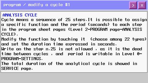
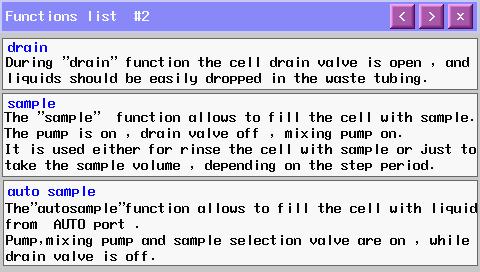
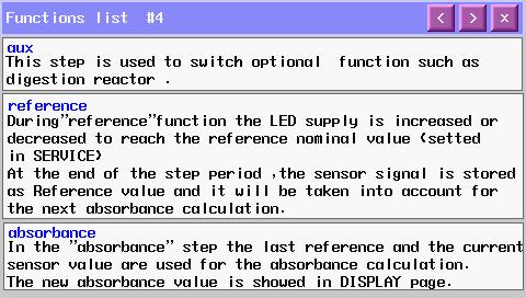
19 Introduction 2.4 ANALYSIS CYCLE PROGRAMMING COMMANDS An analysis time program in the Waltron has the following structure: 1. After rinsing the reaction colorimetric cell and taking a sample, one or more miscellaneous reagents, like buffer or masking agent, may be added after which a first measurement takes place (reference); in this way interfering factors are eliminated such as sample color or turbidity, miscellaneous reagents color and refractive index variations. 2. The second measurement (reading sensor) takes place after addition of color reagent and color development, which may take a certain time period, depending on the color reaction. Table 2.1: The run sequence of colorimetric determination. Conditioning, rinsing and sampling Drain, rinse and sample functions Addition of reagent(s) Add reag function Mixing and wait Mix and wait functions First measurement Reference function Addition of color reagent(s) Add reag function Mixing and wait Mix and wait functions Reading, absorbance and concentration calculation Read sensor, absorbance, calculation Drain, conditioning, rinsing, sampling Drain, rinse and sample functions Waiting time (analysis frequency) Wait function First the cuvette is drained and rinsed (this can also be programmed at the end of the run). In this way the hydraulic line and the colorimetric cell is rinsed as well prior to the actual sample taking. Next a sample is taken. Depending on the method one or more reagents may be added before reference. The mixing pump is activated and the liquid is pumped from the lower part to the upper part of the colorimetric cell. The waiting time is programmed in order to eliminate bubbles, suspensions. Regulation of the light intensity to a programmed value, in order to start from a fixed reference point and eliminate interfering factors (sample turbidity, color). Depending on the method one or more reagents may be added for the color development. The mixing pump is activated and the liquid is pumped from the lower part to the upper part of the colorimetric cell; in this way reagent(s) is mixed. The waiting time is programmed in order to complete the colorimetric reaction. Reading of the light intensity after the colorimetric reaction, calculation of the absorbance and of the concentration. Drain and rinse of the hydraulic line and the colorimetric cell. The wait function allows the user to set the analysis frequency. 18
20 Introduction FLOW DIAGRAM Figure 2.4: Flow diagram ANALYZER OPERATIONS The Waltron performs several operations throughout a cycle. A list of common operations is shown below. Rinse #1 Rinse #2 Drain Sample #1 Sample #2 Add Reagent #1 19

21 Introduction 2.5 FAST LOOP RESERVOIR The external reservoir, required for online applications, allows a fast circulation of the sample coming from the sampling point. Inside the fast-loop reservoir the sample is at atmospheric pressure and this allows the sample pump to provide the analyzer with a constant delivery of smaple and no overpressure. In addition, the fast-loop reservoir holds a small additional quantity of sample to avoid wrong alarms in case of short loss of sample as well as to eliminate air bubbles from the sample line. The stainless steel drain tubing keeps a constant water level inside the container and allows a proper sample circulation to avoid suspended solids accumulation. The sample flow should be adjusted to have the complete sample overflow through the U-shaped stainless steel tube. A small hole at the stainless steel tubing allows the fastloop reservoir to empty for cleaning purposes just with finger pressure. Inside the reservoir a level sensor checks for water presence. The loss of sample switch puts the analyzer into stand-by conditions at the end of the current cycle. When the sample flow resumes in the reservoir, the analyzer will start automatically with a new cycle. NOTE: In the case of dual stream units, there will be two separate fast loop reservoirs, one for each of the sample streams. Air to Overflow Drain Sample to Analyzer Stream Inlet Level Switch Process Sample Overflow Drain Process Sample Inlet (behind overflow tubing) Figure 2.5: Depiction of the fast-loop reservoir. 20
 Figure 2.6: Mounting dimensions for the fast loop reservoir.")
22 Introduction Ø 0.26 (6.5 mm) (259 mm) 5.20 (130 mm) 5.24 (131 mm) 5.84 (146 mm) Figure 2.6: Mounting dimensions for the fast loop reservoir. 21

23 Introduction 2.6 WET-SECTION BOX Sampling Pump 3 Way Valve Sample Inlet Colorimetric Reaction Cell Reagent Pumps Pinch Valve Mixing Pump Sample Drain Figure 2.7: Hydraulic box with components indicated. Sampling Pump The analyzer uses a peristaltic pump for sampling. Pump tubing must have the proper diameter suitable for the pump. The diameter and the material of the tubing is very important; use only Waltron spare parts. 3 Way Valve Allows the analyzer to choose between Sample Inlet 1, Sample Inlet 2 (dual stream units only), and Calibration Standard Inlet for analysis. Sample Inlet The tubing for the sample inlet(s) and calibration standard inlet pass through the housing enclosure on the right hand side of the unit and are connected to the 3 way valve. Colorimetric Reaction Cell The colorimetric reaction cell is made of glass; the diameter is 16 or 25 mm, depending on the parameter. The cell is positioned inside a thermostated block fixed with 2 screws. The block can be easily removed to allow the cleaning of the glass cell. Reagent Pumps The reagents are dosed with peristaltic pumps. The 3048 has one reagent pump. 22

24 Introduction Pinch Valve Normally-closed pinch valve to pinch or open a silicon / viton tubing O.D. ⅜ in order to close or open the drain of the colorimetric cell. The size and the material of the tubing is very important; use only Waltron spare parts. Mixing Pump The sample is mixed with reagents with a membrane mixing pump. The liquid is pumped from the lower part to the upper part of the colorimetric cell. Flow direction (inlet / outlet) of the pump is indicated on it with the symbols Λ and V. Sample Drain The tubing for the sample drain maintains a constant level of few cm of liquid on the colorimetric cell. 2.7 ELECTRONICS The microprocessor and its PCB assembly are located in the electronic section. It provides to control the entire analyzing system. It handles the analyzer operations, it collects all the information and data coming from the different analyzer devices and it controls all the I/O apparatus to dialogue with the user touchscreen interfaces and transfer data equipments. The connections for the external terminal block are shown in Section Pass-thru Cable Glands AC Power Connections (behind cover) External Terminal Block Power Switch Electronics Enclosure Figure 2.8: Electronics box. 23
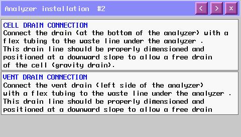
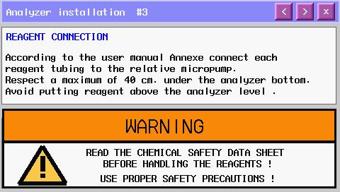
25 Installation 3 INSTALLATION 3.1 RECEIVING The Waltron is assembled and fully tested for proper performance. Before proceeding with analyzer installation, it is recommended to: Check that the box and analyzer have not been damaged during transportation. Take extreme care during analyzer unpacking and moving. Be careful not to misplace accessories during unpacking. Refer to the packing list included. 3.2 ANALYZER HANDLING Take extreme care when lifting or moving the analyzer. Before moving the analyzer, it is recommended to manually empty all of the hydraulic parts of any liquids. 3.3 LOCATION AND MOUNTING It is recommended to install the analyzer in a suitable position: The location is to be clean, covered and properly enclosed to provide the analyzer with good ventilation and low dust concentration. Operating environmental conditions are: temperature between 5 and 50 C at max 80% relative humidity. If the temperature is below 5 C, the analyzer should be installed in a heated cabinet. Because of chemicals and waste gases it is absolutely necessary to have a well ventilated location for the analyzer. The analyzer is supplied with four mounting brackets for wall or stainless steel support rack installation. Use 4 screws M6 or M8 to mount the analyzer. Reagent bottles are supplied with the analyzer. o Relative position of the reagent's bottle(s) versus reagent pump(s) is very important. o Respect the maximum height of about 16 (40 cm) between the bottle(s) and the lowest edge of the analyzer panel. The fast-loop reservoir should be mounted within reach of the sample tubing (approximately 24 (60 cm) in length). 3.4 PRE-INSTALLATION Before installing the analyzer, take the following precautions: Place the analyzer close to the sample point to achieve the minimum response time; the sample should be homogenous and representative. The drain line should be properly dimensioned and positioned at a downward slope to allow the drain of analyzed sample (by gravity) and the overflow coming from external fast-loop reservoir (if used). 24
26 Installation WARNING! The sample drain of the analyzer must be at ambient pressure with no restriction or counter pressure. Please verify that this condition has been strictly respected during installation. Clearance requirements for the analyzer should be about 8 (20 cm) on either side and about 40 (100 cm) in the front. Sufficient space for the reagent containers should be provided on the side or beneath the analyzer. The reagent containers should be positioned in the reagent bracket or a suitable basin in case of spills. NOTE: Respect the maximum height of 16 (40 cm) between the reagent's bottle(s) and the reagent's pump(s). 3.5 MOUTING SCHEMATICS (258 mm) 9.76 (248 mm) (412 mm) (380 mm) (603 mm) (479 mm) Figure 3.1: The dimensions for mounting the analyzer. 25
27 Installation 3.6 ELECTRICAL CONNECTIONS General information: The electrical installation should be carried out by qualified personnel in accordance with national or local regulations. Qualified Personnel means a person who has been fully trained and has professional experience to avoid electrical hazards and dangers. Service qualified personnel will receive the special key to open the analyzer s enclosure. Before servicing the analyzer or its parts that are electrically powered, turn off power to avoid risks of electrocution. To turn off power from an electrical device, it is necessary to interrupt the power line using a circuit breaker or an isolating switch to be sure that there is no power in the area to be serviced. Protection against indirect contacts is guaranteed by efficient grounding of all isolated metal masses. o Grounding screw is located in the upper left position inside the electrical enclosure. o It will be user s task to periodically check and guarantee the efficiency of analyzer s grounding. Users and qualified maintenance personnel must proceed as follows: Be careful of electrical shock and/or electrocutions labels placed on the analyzer. Always isolate power before servicing the analyzer. In case of loss of power, the analyzer stops and automatically restarts into standby mode as soon as power is restored. No maintenance should be carried out on the instrument without first switching off the power AC POWER CONNECTION The Waltron is designed for operation with Vac, 50 Hz power. All the connections must be made in accordance with national or local regulations. The analyzer is equipped with a thermal switch (main power switch). It is always recommended that the analyzer is connected to the mains via a circuit breaker or an isolating switch installed near the unit. To make changes to the AC power connections, it is necessary to remove the electronics enclosure cover. The AC power connections are fed to a connector that sends the power to the ON / OFF switch before reaching the analyzer. The connections are shown below in Figure


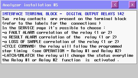
28 Installation USER SIGNAL CONNECTIONS The analyzer provides an External Terminal Block on the outside of the Electronics Enclosure. It allows the operator to connect to an external device such as a sequencer or sampler, monitor the 4-20mA ouputs and monitor alarm relays. The external terminal block can be configured from the SERVICE Screen. Table 3.1 below shows the terminal contact labels starting with pin 1 on the left. Figure 3.2: Electrical connections for user connections and power connections. Table 3.1: Terminal block pin locations. Pin Number Terminal Label Description 1 - Input NO contact from an External Device to tell 2 + Input the analyzer to take a measurement. 3 - Signal mA output for Sample 2 Measurement 4 + Signal Signal mA output for Sample 1 Measurement 6 + Signal 1 7 COM ½ Common for Relay 1 and 2 8 OUT Relay 1 Alarm Relay 1 NO Contacts 9 OUT Relay 2 Alarm Relay 2 NO Contacts 10 OUT Relay 3 Alarm Relay 3 NO Contacts 11 OUT Relay 4 Alarm Relay 4 NO Contacts 12 COM 3/4 Common for Relay 3 and 4 27
29 Installation 3.7 REAGENT INFORMATION The Waltron uses 1 reagent for the colorimetric measurement. Reagent 1: Ferrozine Reagent 3.8 REAGENTS HOLDING BRACKET Use the drawing below to mount the reagents bracket below the analyzer. NOTE: Respect the maximum height of about 16 (40 cm) between the reagent's bottle(s) and the reagent's pump(s). Ø 0.48 (12 mm) (496 mm) (292 mm) 4.00 (102 mm) 1.0 (25 mm) 7.00 (178 mm) Figure 3.3: Mounting schematics for the reagent holding bracket. 28
30 Analyzer Initial Start-Up 4 ANALYZER INITIAL START-UP Before proceeding with analyzer start-up it is absolutely necessary to check that all procedures for a proper installation and reagent preparation have been made. Please verify that all the suggestions and recommendations have been respected. 4.1 PREPARING THE ANALYZER FOR START-UP Once installation is complete, proceed as follows to prepare the analyzer for online operation : 1. Connect the sample line inlet tubing (or filtered sample outlet coming from optional filtration system) to the fast-loop reservoir installed on the left side of the analyzer 2. Connect the drain fitting of the fast-loop reservoir to the waste line 3. Put the reagent inlet tubings into the appropriate reagent containers a. Reagent 1 = Ferrozine Reagent 4. Put the calibration solution inlet tubing into the calibration solution positioned beneath the analyzer 5. Connect the analyzer drain tubing to waste drain line WARNING! The drain of the analyzer must be at ambient pressure with no restriction. Please verify that this condition has been strictly respected during initial start-up procedures. 6. Check sample presence in fast-loop reservoir and adjust the sample flowrate so that there is complete reservoir discharge when a finger is covering the hole at the top of the stainless steel drain line 7. Turn the analyzer on using the switch in the electronics compartment 8. Perform reagents prime (see Section 6.1) 9. Perform calibration (see Section 6.2 & 6.3) 10. Set the analyzer to online mode (see Section 6.5) 29

31 User Interface 5 USER INTERFACE 5.1 USER INSTRUCTIONS The user s interface consists of the touchscreen located on the front panel of the analyzer enclosure. All the output/input data, information, alarms and fault conditions are shown on the display while all the commands and settings may be transferred to the analyzer simply pressing the touchscreen buttons. Figure 5.1: User interface main display screen. 5.2 USER PASSWORD Table 5.1: User password. First Level Password (service) 1111 Second Level Password (admin.) Contact Waltron Table 5.2 shows the menus and sub-menus that are available based on which level of password is input. Table 5.2: Menu access level with password. No Password Service Password Admin. Password Main Menu Program Menu Analysis Display Menu Manual Step Cycle Display Menu Display process values Program Menu Calibration Menu Program Menu Extra Cycle Program Menu Settings Service Menu Help Menu 30
32 User Interface 5.3 MAIN SCREEN The main screen displays: Name of the analysis program (Iron Analyzer) Login **** window (two levels of password); pressing on **** the user can input the 4 number password Buttons that allow access the sub-menus (Run, Display, Program, Service and?) Value (ppm or ppb) of the last analysis Alarms / relays Active step of the analysis in progress Reagent(s) consumption (%) Table 5.3: Analyzer operating statuses. ANALYZER OPERATING STATUS STAND-BY The analyzer is waiting for a user s command (for example when the analyzer is switched on after a shutdown), after single cycle analysis, or when the operator has forced a stop in stand-by at the end of the current online / single cycle by pressing the button previously activated a second time. SINGLE CYCLE ON-LINE MANUAL STOP The analyzer is performing a single analysis cycle. As soon as the cycle is completed the analyzer will go into the stand-by condition. The analyzer is performing a continuous cyclic analysis based on the steps set in the PROGRAM menu (Analysis Cycle) and started when the START ON LINE button has been pressed. As soon as the analyzer completes an analysis cycle, it will restart with a new analysis. This condition is identified as the online condition. The analyzer has been forced to stop. A message in the main menu shows the manual stop and the fault alarm is initialized. RUN DISPLAY Table 5.4: Main menu button descriptions. MAIN MENU BUTTONS This menu allows the user to put the analyzer into online measurement mode or run a single analysis cycle on stream 1 or stream 2. The user can also stop the analyzer with the emergency stop button. This menu displays all analysis data, the active step of the current analysis cycle with the time counter, the sensor's signal trend graph, and allows access to the manual step functions. PROGRAM This menu allows access to the calibration menu, enabling and disabling the loss of sample alarm, the 4-20 ma output, and settings of the analyzer. SERVICE Second level admin password required. This menu allows access to the analysis parameter, time, blank value, and regulation of the 4-20 ma output, led, and reference.? This menu shows the help user guide. 31

33 User Interface 5.4 REAGENTS REFILL The remaining reagent is shown as a percent (%) at the bottom of the main display screen. If the reagent level falls below a value of 4%, the analyzer goes into FAULT status and stops automatically. The alarm message will be displayed in the main menu and the FAULT contact will be activated. Every time the reagents are refilled, it is necessary to reset the value to 100%. 1. Press on the value % of each displayed reagent. 2. Bottle Reag. 1,2,3 Filled? YES. Figure 5.2: User interface screen for Reagents Refill. 32
. This condition is identified as online and ONLINE is displayed on the button.")
34 User Interface 5.5 RUN MENU Figure 5.3: User interface after pressing the RUN Menu. START ON-LINE: This button puts the analyzer into continuous online operation. The analyzer will perform a continuous cyclic analysis based on the steps set in the PROGRAM menu (Analysis Cycle). This condition is identified as online and ONLINE is displayed on the button. Pressing the button again will cause the analyzer to finish the cycle in progress and put the analyzer in stand-by mode. CH 1: This command will perform a single analysis cycle on stream 1. At the end of the cycle, the analyzer will go into stand-by mode and wait for the user s next command. CH 2 (available on dual stream units only): This command will perform a single analysis cycle on stream 2. At the end of the cycle, the analyzer will go into stand-by mode and wait for the user s next command. EXTRA: This command will perform a cycle based on the programming of the extra cycle. The default programming for the extra cycle is set to a CALIBRATION cycle. EMERGENCY STOP: This command will immediately stop the analyzer at the current step of the analysis in progress. The analyzer will go into the MANUAL STOP condition. On the main screen appear the message manual stop red coloured and the FAULT alarm contact will be activated. To restart the analyzer after an emergency stop, it is necessary to reset the fault by pressing the yellow colored RESET EM. STOP. This will force the analyzer to stand-by conditions. 33
 Reading: shows the reading of the sensor (second point for absorbance calculation) Absorb.")
35 User Interface 5.6 DISPLAY MENU Figure 5.4: User interface in the DISPLAY Menu DISPLAY PROCESS VALUES The following is a list of the data displayed in this menu (read-only values): Sensor : shows the current measurement of the sensor Refer.: shows the reference value (first point for the absorbance calculation) Reading: shows the reading of the sensor (second point for absorbance calculation) Absorb.: displays the last absorbance value calculated Blank : shows the most recent blank value Led: shows the led supplied Valid. %: it shows the validation value in %, compared to the calibration value Current operation: this window displays the current analysis step and the time in progress (countdown for every step programmed) CHART It displays in a graphic the sensor's signal trend during the current analysis cycle MANUAL STEP This button allows to access to the manual commands of each programming step (see list in the Section 2.3.1) separately. The operator could decide the single operation to run (select function) and the time of the operation. This function is protected with the 1st level of password and is available only when the analyzer is in stand-by mode. 34


36 User Interface Figure 5.5: Manual step functions shown in the bottom left corner DATA LOGGER From the DISPLAY menu, pressing the Data Logger button in the upper right hand corner will display the previous 500 results. Figure 5.6: Data logger screen of the user interface. 35


37 User Interface 5.7 PROGRAM MENU Figure 5.7: User interface after pressing the PROGRAM Menu. The PROGRAM Menu allows access to the following operations: SETTINGS: Allows the user to set the ratio of the analysis cycles versus the extra cycles, the alarm value (low or high) and to enable or disable the loss of sample alarm and the 4-20 ma output. CALIBRATION MENU: This function is protected with the 1st level of password. Allows the user to set the value of the standard used for calibration and to perform blank and calibration cycles SETTINGS MENU Figure 5.8: The SETTINGS Menu and options are displayed. 36

38 User Interface Cycles ratio: Programs the ratio of the analysis cycles versus the extra cycle (calibration cycle). For example, 400 analysis to 1 extra cycle means that every 400 analysis cycles the analyzer will perform 1 calibration cycle. Cycle wait: Sets the time between analysis cycles when the analyzer is in on-line mode. Result alarm: Programs the low / high value alarm. The alarm is expressed in % of the full scale. Output Signal: Enables / disables the 4-20 ma output. Datalog: Enables / disables the internal data logger. Sample Alarm: Enables / disables the loss of sample alarm CALIBRATION MENU Allows the user to display and set the value of the standard used for calibration and perform manual blank and calibration cycles (refer to Section 6). Figure 5.9: User interface at the CALIBRATION Menu. 37
39 User Interface 5.8 SERVICE MENU Acess to the SERVICE Menu requires the second level password for the admin login. The SERVICE Menu allows the user to configure the external terminal block connections. Configure the External Control On the Service screen change the External Input selection from NONE to either ONLINE or EXTRA CYCLE (i.e., Calibration). Setting the range for the 4-20mA Sample 1 Output Set the range of the 4-20mA Sample 1 Output with the F Scale1 selection. The default range is equal to the range of the analyzer. Setting the range for the 4-20mA Sample 2 Output Set the range of the 4-20mA Sample 2 Output with the F Scale2 selection. The default range is equal to the range of the analyzer. This setting only applies to dual stream analyzers. Configuring Relay 1, 2, 3 and 4 There are 4 cells on the service screen to configure Relay 1, Relay 2, Relay 3 and Relay 4. Touch one of these cells and select the parameter to activate the relay: Result Alarm The measurement is greater than the % specified on the Settings screen. For example: If the Result Alarm on the Settings screen is set to greater than 50%, the relay will close when the measurement goes above 50% of the analyzer range. Loss of Sample 1 The relay will close when the flow on Sample 1 is lost. Loss of Sample 2 The relay will close when the flow on Sample 2 is lost. Fault Alarm The relay will close when a Fault Alarm occurs such as - Pressing the EMERGENCY STOP button. Alarm is cleared by pressing RESET in the RUN window. - Reagent went below 4%. Alarm Cleared by refilling reagent bottles and setting the level to 100%. Cycle Command When testing the relay, set the relay mode to Cycle Command. GO to the Display screen and press the Manual button. Scroll through the options and select Relay #1. Set the activation duration and press ON. The Relay #1 contacts will close for the designated duration. 38
40 User Interface 5.9 HELP MENU The internal HELP Menu can be accessed by pressing the? on the main display screen. The help menu has the following sub-menus that can be viewed directly from the analyzer and can also be found in Appendix B. Figure 5.10: User interface showing the topics in the HELP Menu. 39
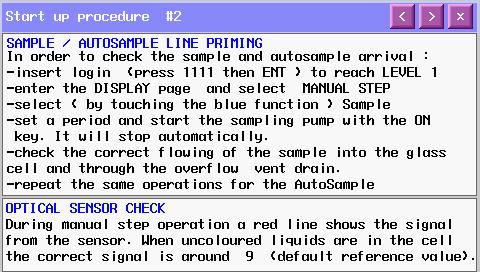
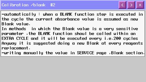
41 Operation 6 OPERATION Colorimetry is a relative method, therefore an initial calibration is needed before measurement can be performed. This is done using standard solutions and analyzing them in the same way as the sample. In order to ensure correct measurement performances, the analyzer should be calibrated periodically. The blank is taken with DI water. The system slope is controlled by a comparison to a standard solution of known concentration. Calibration allows the analyzer to adjust: Blank of the system Slope of the system (factor calibration) The calibration can be done manually or automatically. 6.1 REAGENTS PRIME Prior to the initial calibration of the analyzer, the reagent lines must be primed. This procedure should also be performed every time the reagents are refilled or replaced. 1. Login with the 1st level service password (1111). 2. Press the DISPLAY button on the touchscreen and then press the button MANUAL STEP. 3. Select SAMPLE function for 20 seconds. 4. Select ADD REAG (1) functions for 40 seconds each in order to prime the three reagent lines. Visually confirm that reagent is being drawn into the lines and into the flowcell. If no reagent is seen, it may be necessary to repeat the ADD REAG function. 5. Select DRAIN function for 5 seconds. 6. Select SAMPLE function for 20 seconds. 7. Repeat steps 5 and 6 to rinse the flowcell. 8. Check the drain tube of the pinch valve is correctly positioned and select the DRAIN function for 5 seconds. 6.2 BLANK CALIBRATION A blank calibration should be performed after reagent replacement and every time a manual calibration is required. 1. Login with the 1st level service password (1111). 2. Disconnect the sample tubing from the fast-loop reservoir and connect it to a DI water source. 3. Perform an analysis cycle by pressing the RUN Menu and selecting CH 1. It is recommended to proceed with a blank refreshment after performing three analysis cycles with DI water to flush the system. The absorbance detected by the analyzer is assumed to be absorbance produced by reagent(s) and DI water. 4. To store this value as the blank, from the PROGRAM menu, select the CALIBRATION 40
42 Operation Menu. 5. Press and hold down the BLANK key. This will refresh the stored BLANK value; it can be refreshed only after a completed analysis cycle with the analyzer in stand-by mode. 6. Reconnect the sample line to the fast-loop reservoir. 6.3 SLOPE (FACTOR) CALIBRATION A manual factor (slope) calibration should be performed during the initial start-up, after reagent replacement, and after any period of extended shut-down. The recommended and default setting for automatic calibration is approximately once per week. 1. Login with the 1st level service password (1111). 2. Connect the CAL tube to the calibration standard. 3. Check that the calibration standard is the correct concentration. a. From the PROGRAM Menu, select CALIBRATION. b. The concentration of the standard is displayed in blue. c. To change the standard concentration, press the displayed standard value. d. Type the new concentration and select ENT. 4. From the RUN Menu, select EXTRA. The analyzer will perform a calibration cycle and store the new calibration factor. 5. Perform an EXTRA Cycle two to three times with the calibration standard to ensure a repeatable calibration factor. 6. To check the value of the calibration factor, from the PROGRAM Menu select CALIBRATION to open the calibration menu window. 6.4 SINGLE ANALYSIS CYCLE The analyzer can be set to run either in continuous analysis mode or single analysis mode. Follow the steps below to perform a single analysis cycle. NOTE: When starting the analyzer for the first time or restarting it from any period of shutdown, do not proceed to run an analysis cycle until a calibration has been performed. 1. Connect the sample tubing to the fast-loop reservoir and turn on sample flow to the fast loop reservoir. 2. Check that the sample fills the fast loop reservoir so that the float switch rises and sample is being discharged from the overflow drain. 3. Perform an analysis cycle by pressing the RUN Menu and selecting CH 1. The absorbance detected by the analyzer is used along with the blank and calibration values to determine a concentration in ppb. 4. When the analyzer has finished the analysis cycle, the concentration reading will be displayed on the main screen. The result can also be found in the data logger. 5. The analysis returns to standby mode and waits for another user command. 41
43 Operation 6.5 ONLINE MEASUREMENT In online mode, the analyzer will run perform consecutive analysis cycles until it is manually stopped or the out of sample alarm is tripped. NOTE: When starting the analyzer for the first time or restarting it from any period of shutdown, do not proceed to put the analyzer into online operation until a calibration has been performed. 1. Connect the sample tubing to the fast-loop reservoir and turn on sample flow to the fast loop reservoir. 2. Check that the sample fills the fast loop reservoir so that the float switch rises and sample is being discharged from the overflow drain. 3. Put the analyzer into online measurement mode by pressing the RUN Menu and selecting START ON LINE. The absorbance detected by the analyzer is used along with the blank and calibration values to determine a concentration in ppb. 4. When the analyzer has finished the analysis cycle, the concentration reading will be displayed on the main screen. The new result and previous results are stored in the data logger (up to 500 measurement results). 5. The analyzer will wait the user defined amount of time (see Section 5.7.1) and then proceed to run additional analysis cycles. 6. To bring the analyzer out of online operation, press the RUN Menu. The top box where START ONLINE was previously, will now be blank and dark gray. Pressing this box will tell the analyzer to complete the current analysis cycle and go into stand-by mode at its completion. 6.6 GRAB SAMPLE The grab sample feature allows the user to measure the concentration of an external sample. NOTE: When starting the analyzer for the first time or restarting it from any period of shutdown, do not proceed to run a grab sample analysis until a calibration has been performed. 1. If the analyzer is in online operation, it is necessary to put it into standby mode. Press the RUN Menu and select the START ON LINE button (blank, dark gray box on the top of the RUN Menu). The analyzer will finish the analysis cycle that is currently in progress and go into standby mode. 2. Turn off sample flow to the fast loop reservoir. 3. Disconnect the sample tubing from the fast-loop reservoir and connect it to the grab sample source. The grab sample source should have at least 200 ml of sample present. 4. Perform an analysis cycle by pressing the RUN Menu and selecting CH 1. 42
44 Operation 5. When the analyzer has finished the grab sample analysis cycle, the concentration reading will be displayed on the main screen. The result can also be found in the data logger. 6. The analysis returns to standby mode and waits for another user command. 7. When the user is finished with the grab sample analysis, make sure to reconnect the sample tubiing to the fast loop resevoir. 8. Turn on sample flow to the fast loop resevoir. 9. Put the analyzer back into online operation mode by pressing the RUN Menu and selecting START ON LINE. 6.7 EMERGENCY STOP The analyzer has an emergency stop function that will stop the analyzer immediately during any analysis cycle that it is performing. 1. Press the RUN Menu. 2. Select EMERGENCY STOP. The analyzer will stop its current function and return to the main display screen. The emergency stop fault alarm will be activated. 3. To put the analyzer into standby mode after an emergency stop, press the RUN Menu. 4. The menu will now show RESET in the posistion that emergency stop was listed previously. 5. Select RESET to deactivate the alarms and return the analyzer to the main display screen in standby mode. NOTE: After initiating an emergency stop, there may be sample and reagents remaining in the analyzer. It will be necessary to flush the system before performing a new analysis cycle. 43
45 Maintenance 7 MAINTENANCE 7.1 SCHEDULED MAINTENANCE Basic maintenance of the Waltron 3048 Analyzer requires that the reagent containers are refilled or replaced and that the colorimetric cell is cleaned on a regular basis. In addition, the user should perform a regular 'visual overall-check' of the wet part for immediate corrective measures, e.g. in case of leakages etc. Cleaning of the analyzer cabinet is best performed using a soft, nonaggressive cleaner. The use of a logbook for cataloging reagent refilling, corrective measures and scheduled maintenance is strongly recommended. During the performance of the basic maintenance work, as described in this chapter, the analyzer can not be operational. Prior to the maintenance work, all necessary precautions regarding personal safety (protective clothing, safety glasses etc.) are to be taken into consideration. Always be sure to label and rinse all connected tubing with water prior to removal. Waltron Colorimeter is based on colorimetric analysis methods, using chemical solutions. Make sure that proper safety precautions are taken (e.g. using safety gloves and glasses) during handling the chemical solutions. List of scheduled maintenance: Visual check Everytime that it is possible, visually check the following items: Liquid leakages Cell sample level (during cycle) Glass cell cleaness condition Reagent level % Monthly Visual overall check Colorimetric cell cleaning Reagent(s) replacement (reset reagent counters) Reagent pump(s) priming Calibration blank with DI water, slope with calibration solution Every 2 months Pinch valve drain tubing replacement Every 4 months Peristaltic pumps tubing replacement 44
46 Maintenance Every 6 months 3 ways valve cleaning, manually with a syringe Colorimetric cell o-ring replacement Fittings cleaning / replacement Annually Hydraulics and sample tubing replacement Analyzer general inspection (for qualified personnel only) Table 7.1: Scheduled manintenance reference chart. OPERATION FREQUENCY Daily Monthly 2 Mos. 4 Mos. 6 Mos. Annually Visual check of FAULT alarm indicator Visual check of liquids enclosures for leakages detection X X Visual check of reagents level Sample fast-loop reservoir cleaning Colorimetric cell cleaning Reagents replacement (reset reagent counters) Pinch valve tubing replacement Pump tubing replacement X 3 way valve and fittings cleaning X X X X X X Colorimetric cell O-ring replacement Hydraulics and sample tubing replacement Analyzer general inspection (for qualified personnel only) X X X 45


47 Maintenance 7.2 PUMP TUBING REPLACEMENT The peristaltic pump head is located in the fluidics section. Before replacing the tubing, please read the hazards and dangers list in section 1 and health and reagents safe data sheets. It is also recommended to wear adequate clothes, gloves and eyes protection and take extreme care sample spills during tubing replacement. Proceed as follows: 1. Stop the analyzer 2. Using the key, open the liquids enclosure 3. Manually unscrew the four wings nuts which hold the pump head in place. 4. Disconnect the pump tubing from its inlet and outlet fittings, taking extreme caution of liquid spills 5. Slide the pump head to the left and remove the pump head 6. Separate the two halves, taking care of the rotor, and remove the used tubing, taking caution of spills 7. Place the pump half containing the rotor in one hand and place the rollers in the 2, 6 and 10 o clock positions. Place tubing in the outer port and against the two rollers as shown, keeping your thumb on the tubing to hold it in place, insert tubing key on the back of the rotor shaft and push in as far as possible. Tubing is now positioned in deep into the pump head body. With the key firmly pressed against the rotor, turn counterclockwise and push down while turning until tubing has surrounded the rotor 8. Tubing is now in place. Remove key and position other pump half into the rotor shaft and snap shut. Be careful not to pinch tubing between plastic pump halves 9. Check if the pump turns correctly using the key 10. Finger tighten the pump head slide it into the mounting screws moving the roller block with the key or with a screwdriver until the shaft aligns with the motor drive 11. Secure the four wing nuts by finger tightening until they have a firm mounting of the pump head 12. Restart the analyzer Figure 7.1: Pump tubing replacement. 46
48 Analyzer Shut-Down 8 ANALYZER SHUT-DOWN It is important to know that the analyzer should run continuously, if possible. For a short downtime of the 3048 analyzer (from 1 to 3 days), it is recommended to put all the inlet tubing (reagents and sample source) in a DI water source and leave the unit running in these conditions. For long shut down period, please proceed as follows: 1. Replace the reagents in the container with distilled water and perform a priming of all the pumps with DI water. a. Login with the 1st level service password (1111). b. Press DISPLAY > MANUAL > STEP > ADD REAG 1 for 40 seconds. 2. Disconnect the sample line and fill the fast-loop reservoir (if present) with DI water. 3. Run the analyzer for at least 2 cycles with all of the reagent tubes placed in a DI water container. 4. Empty the hydraulic line of water. 5. Put the analyzer in stand-by mode. 6. Turn off the analyzer main power by disconnecting the plug from the power line. 47
49 Troubleshooting 9 TROUBLESHOOTING For troubleshooting tips and solutions, refer to the HELP Menu. The HELP Menu can be found through the user interface of the analyzer and in Appendix B of this manual. Table 9.1: Alarm descriptions. Alarm Message Alarm Description Action Required Reagent <10% One or more reagent bottles is low Check the level of the reagent bottles and refill as necessary Zero Failure The Refernce Failed Check the water level in the sample cell Loss of The sample to stream 1 Check the flow of Sample #1 Sample 1 is lost Loss of Sample 2 The sample to stream 2 is lost Check the flow of Sample #2 Dual stream analyzers only Someone felt it was Determine why Emergency Stop was Emergency necessary to press the pressed, correct problem and then press the Stop Emergency Stop button RESET button on the RUN window. Cal Error Result Alarm The Calibration Factor is out of Range. Measurement is greater than the % on the Settings screen 1. Check the level of the reagent bottles, 2. Make sure reagent pumps are primed 3. Check reagent pump dosage 4. Check Cal Sample level 5. Verify analyzer is draining properly The sample is out of range. Corrective action required. 48
50 Spare Parts 10 SPARE PARTS Description Table 10.1: Routine Maintenance Parts Listing. Part Number Annual Consumables Kit W Pinch Valve Drain Tubing W Sample Pump Tubing W Sample Line Tubing W Peristaltic Reagent Pump Kit (tubing, fittings, rollers) W Description Table 10.2: Standards and Reagents Parts Listing. Part Number Iron Reagent #1 W Iron 50 ppb Calibration Standard (0-100 ppb range) W Iron 150 ppb Calibration Standard (0-300 ppb range) W A Description Table 10.3: Spare Parts Listing. Part Number Pump Head 7016 sampling pump W Pump motor rpm 24 Vdc W Sample level sensor W External reservoir - Fast loop with level switch W Peristaltic pump for reagents W Reaction quartz cell 24 mm W Heated block for 24 mm quartz cell W Heater W Mixing pump PP EPDM W Drain Pinch Valve W Flowcell Cap with Tubing and Fittings (1 Reagent) W Ways Valve (D351) W Sample Selection Block with 1 Valve (Single Stream Unit) W Sample Selection Block with 2 Valves (Dual Stream Unit) W Power supply 24 Vdc W Touchscreen W Preamplifier photometer board W Led 572 nm with connector W Electronics, Complete W Display Cable W Output Cable for User Connections W


51 Appendix A Panel Mount Schematics APPENDIX A PANEL MOUNT SCHEMATICS 50

52 Appendix A Panel Mount Schematics 51


53 Appendix B Help Menu APPENDIX B HELP MENU 52

54 Appendix B Help Menu 53


55 Appendix B Help Menu 54


56 Appendix B Help Menu 55


57 Appendix B Help Menu 56


58 Appendix B Help Menu 57


59 Appendix B Help Menu 58


60 Appendix B Help Menu 59


61 Appendix B Help Menu 60


62 Appendix B Help Menu 61
63 Appendix C Multiple Stream Sequencer APPENDIX C MULTIPLE STREAM SEQUENCER Introduction The Multistream Sequncer is an external accessory for the automatic, continuous multiplexing of up to four sample streams to one on-line 3040 Series colorimetric analyzer. The sequencer is connected to the analyzer via a 4 wire cable which provides communication and power supply to the external unit. Once connectted, the analyzer is linked to the sequencer and displays the process value, alarm status, channel status and time during operation for all of the active channels. Storage of event/alarm log and measurement values for all channels inside analyzer's datalogger. A sampling valves manifold is mounted on the sequencer plate and ensures sample is available for switching between streams. The fast loop reservoir with level switch is mounted on the sequencer to provide the flow alarm in case of loss of sample in any of the streams. The sequencer is factory tested and ready for installation and operation. Specifications Power supply: Tthe sequencer is powered by the colorimetric analyzer (voltage VAC, 50/60Hz) Table C.1: Multistream sequencer sample conditions. Flow Rate: ml/min per stream Temperature: 5-45º C (41-113º F) Inlet Pressure Max: 0.5 bar (4 PSI) Outlet Pressure: Ambient pressure Table C.2: Multistream sequencer technical specifications. Electronics Case: Aluminum Protection Degree: IP54 or IP65 upon request Electrical Connections: Screw clamps Panel Dimensions: x 7.87 x 7.91 (400mm x 200mm x 201mm) Weight: 8.8 lbs (4 kg) 62
 3.66 (93 mm) Figure C.")
64 15.75 (400 mm) Appendix C Multiple Stream Sequencer 7.87 (200 mm) 7.91 (201 mm) 3.66 (93 mm) Figure C.1: Dimensons of the Multistream Sequencer. 63
65 Appendix C Multiple Stream Sequencer Installation Procedure a. Locate a wall with a suitably smooth surface to mount the sequencer for wall mounting. b. Mark 4 holes on the wall for the position of the sequencer. c. Drill 4 holes for M8 screws. d. Mount the sequencer on the right side of the analyzer. e. Ensure that the sequencer is mounted securely in place. Figure C.2: Suggested installation layout of the multistream sequencer. 64
66 14.65 (372 mm) Appendix C Multiple Stream Sequencer Ø 5/16 N 4 M (129 mm) Figure C.3: Mounting Dimensions for multistream sequencer. 65

67 Appendix C Multiple Stream Sequencer Electrical Connections Connect the fast loop reservoir to the connector of the sequencer on the top of the electronic box. Figure C.4: Accessing the electronic box of the multistream sequencer. Connect the 4-20 ma outputs: 1. Open the electronic box of the sequencer. 2. Connect the outputs, ensuring you get the right polarity. 3. Close the electronic box of the sequencer. Figure C.5: 4-20mA output of the multistream sequencer. 66
 and the overflow coming from external fast-loop reservoir WARNING!")
68 Appendix C Multiple Stream Sequencer Hydraulic Connections The installation site should be as near the sampling point as possible to reduce delay in response time. The drain line should be properly dimensioned and positioned at a downward slope to allow the drain of analyzed sample (for gravity) and the overflow coming from external fast-loop reservoir WARNING! The drain of the analyzer must be at ambient pressure with no restriction. Please verify that this condition has been strictly respected during installation. Sample Connections: 1. Connect the sample line inlet tubing to the sampling valves manifold according to the labels. 2. Connect the drain of the fast-loop reservoir to the waste line. Figure C.5: Multistream sequencer hydraulic connections. 67

69 Appendix C Multiple Stream Sequencer User Interface Analyzers that are equipped with the multistream sequencer will have the following user interface screens and menus. Main Page The user can touch anywhere in the white part of the main page to gain access to the sequencer main page. Figure C.6: Multistream sequencer main page of the user interface. The CH+ button will be enabled after login with the service password. This button allows the user to manually open each valve of the sequencer manifold. This function should be used with the analyzer in stand-by mode. The CH1, CH2, CH3, and CH4 buttons will be enabled after login with the admin password. These buttons allow the user to enable or disable each channel. 68

70 Appendix C Multiple Stream Sequencer Pressing RUN, the following page will be displayed: Figure C.7: Multistream sequencer RUN Menu of the user interface. START ON-LINE: This button puts the analyzer to online operation. The analyzer will perform a continuous cyclic analysis with the sequence CH1, CH2, CH3, CH4 of the active channels selected. This condition is identified as online and ONLINE is displayed on the button. Pressing the button again will cause the analyzer to finish the cycle in process and put the analyzer in stand-by mode. SINGLE: This command allows the user to perform an analysis cycle on the active channel. At the end of the cycle, the analyzer will go into stand-by mode and wait for the user s next command. EXTRA: This command will perform a cycle based on the programming of the extra cycle. The default programming for the extra cycle is set to a CALIBRATION cycle. EMERGENCY STOP: This command will immediately stop the analyzer at the current step of the analysis in progress. The analyzer will go into the MANUAL STOP condition. On the main screen appear the message manual stop red coloured and the FAULT alarm contact will be activated. To restart the analyzer after an emergency stop, it is necessary to reset the fault by pressing the yellow colored RESET EM. STOP. This will force the analyzer to stand-by conditions. 69
Silica, Phosphate, Hydrazine Analyzers Series 2140 Specifications
 Silica, Phosphate, Hydrazine Analyzers Series 2140 Specifications 70-82-03-62 September 2009 Introduction REVOLUTIONARY PATENTED TECHNOLOGY Our Colorimetric Analyzers are based on the new patented Loop
Waltron AQUALERT DIVISION
 Waltron AQUALERT DIVISION Water Chemistry Measurement & Control Aqualyzer 2410 Oil and Water Analyzer Instruction Manual Revision 2.50-1- OUR COMMITMENT TO OUR CUSTOMERS The instruction manual that you
Series 5000 Hydrazine Analyzer Model 60002
 Series 5000 Hydrazine Analyzer Model 60002 T he patented* Series 5000 Hydrazine Analyzer is a continuous-reading instrument using the p-dimethylaminobenzaldehyde method of analysis for colorimetric measurement
SAMPLE MANUAL - INSTALLATION - FOR REFERENCE ONLY. ChemScan mini Analyzer. Parameter. Method #### Installation, Operation & Maintenance Manual
 Parameter Method ####, Operation & Maintenance Manual Rev 3/26/2018 Contact Information Document Information Customer Name: Plant Name/Location: Date: Analyzer Serial #: ASA, Inc. (Applied Spectrometry
Flopurge TS. Operation Manual
 Flopurge TS Operation Manual Part Number 079-0204 Spectron Gas Control Systems United Kingdom Unit 4, Herald Court, University of Warwick Science Park, Coventry, CV4 7EZ +44 (0)24 7641 6234 sales@spectron-gcs.com
Hydrazine Analyzer Series 2171 Specifications
 Hydrazine Analyzer Series 2171 Specifications 70-82-03-64 November 2009 Introduction The 2171 is the most advanced hydrazine instrument specifically developed for use in continuous measurement and determination
Flostop TS D7E and A8E. Operation Manual
 Flostop TS D7E and A8E Operation Manual United Kingdom Spectron Gas Control Systems Ltd, Unit 4, ATU1, University of Warwick science Park, Coventry, +44 (0) 24 7641 6234 sales@spectron-gcs.com Germany
Instructions for installation and use English. More documents on: H B /09
 TM Instructions for installation and use English EN More documents on: www.zodiac-poolcare.com H0538700.B - 2015/09 Read this manual carefully before installing, maintaining or repairing this appliance!
Improve Performance and Reduce Maintenance Costs. Model Q45D. Dissolved Oxygen Monitor...
 Improve Performance and Reduce Maintenance Costs Model Q45D Dissolved Oxygen Monitor... Why Throw Away Money? Why Throw Away Money? ATI s Model Q45D Dissolved Oxygen monitor is designed to provide reliable
ph COOLING TOWER CONTROLLER
 LAKEWOOD INSTRUMENTS MODEL 350 ph COOLING TOWER CONTROLLER INSTRUCTION MANUAL SERIAL #: Lakewood Instruments 7838 North Faulkner Road, Milwaukee, WI 53224 USA Phone (800) 228-0839 Fax (414) 355-3508 http://www.lakewoodinstruments.com
HIn3550 Magnetic Field Monitor User's Manual
 HIn3550 Magnetic Field Monitor User's Manual Copyright 1993 by Holaday Industries, Inc. Manual #600053 10/97 $12.50 Revision Record Manual #600053 HIn3550 Magnetic Field Monitor Revision Description Date
HI COD REACTOR and Test Tube Heater 2008 Series
 Instruction Manual HI 839800 COD REACTOR and Test Tube Heater 2008 Series www.hannainst.com This Instrument is in Compliance with the CE Directives 1 Dear Customer, Thank you for choosing a Hanna product.
IntelliDoX Operator Manual
 IntelliDoX Operator Manual OPERATOR MANUAL TABLE OF CONTENTS Table of Contents Table of Contents...1 About this Publication...3 Important Safety Information: Read First...4 Getting Started...5 About the
Table of Contents 1. OVERVIEW SYSTEM LAYOUT SPECIFICATIONS FUNCTION... 11
 Table of Contents 1. OVERVIEW... 3 2. SYSTEM LAYOUT... 4 3. SPECIFICATIONS... 8 3.1 SYSTEM COMPONENTS...9 3.2 PLC INPUTS AND OUTPUTS...9 3.3 FUNCTION KEYS...10 3.4 DEFAULT SET POINTS AND TIMERS...10 4.
Series: MBC1-TC Mini Benchtop Temperature Controller
 User s Guide Series: MBC1-TC Mini Benchtop Temperature Controller Imagine Instruments LLC:: 4500 Williams Drive, Ste 212-318 :: Georgetown, TX 78633 :: p. 855.574.6243 e-mail: info@imagineinstruments.com
APC BC300 Series 40kW 208/450/480V User Guide
 APC BC300 Series 40kW 208/450/480V User Guide Copyright 2002 APC Denmark ApS This manual is subject to change without notice and does not represent a commitment on the part of the vendor Thank You Thank
SAFETY CERTIFIED MODEL FP-700 COMBUSTIBLE GAS DETECTOR
 SAFETY MANUAL SIL 2 Certified Model FP-700 Combustible Hydrocarbon Gas Sensor Version 2.0 1 SAFETY CERTIFIED MODEL FP-700 COMBUSTIBLE GAS DETECTOR This manual addresses the specific requirements and recommendations
Warranty Registration
 WARRANT Y AND LIMITS OF LIABILIT Y Vulcain Inc. warrants to the original purchaser that its product, and the component parts thereof, will be free from defects in workmanship and materials for a period
ModSync Sequencing System Installation & Operation Manual. For use with Fulton Steam Boilers.
 ModSync Sequencing System Installation & Operation Manual For use with Fulton Steam Boilers. Revision 3.0 8/21/2008 - 2 - Table of Contents Introduction Page 4 Features Page 4 Sequence of Operation Page
Instruction Manual PCS-400-XY. Pump Controller. Y=2: 4-20 ma Y=6: 0-10 VDC X=5: 1-5 VDC. 4 Pump Control Relays 1 Alarm Relay 1 Signal Fail
 Manufacturers of Process Controls and Instrumentation Instruction Manual Model: Function: Input: PCS-400-XY Pump Controller X=2: 4-20 ma X=5: 1-5 VDC X=6: 0-10 VDC X=7: Output: Power: 4 Pump Control Relays
M770 ph Controller Owner s Manual
 M770 ph Controller Owner s Manual Table of Contents I. Introduction page 2 A. Water Chemistry page 2 B. Safety page 3 C. System Components page 4 D. Specifications page 7 E. Controller Panel Descriptions
SM3000 Videographic Recorder. User Guide. Modbus (RTU) Communications Option
 Communications Option") SM3000 Videographic Recorder User Guide (RTU) Communications Option ABB The Company We are an established world force in the design and manufacture of instrumentation for industrial process control, flow
SM3000 Videographic Recorder User Guide (RTU) Communications Option ABB The Company We are an established world force in the design and manufacture of instrumentation for industrial process control, flow
Free Chlorine Measuring System
 Product Data Sheet PDS 71-FCL/rev.H September 2008 Model FCL Free Chlorine Measuring System COMPLETE SYSTEM INCLUDES sensor, connecting cable, analyzer, and flow controller. CONTINUOUS ph CORRECTION eliminates
Installation instructions. For the heating engineer. Installation instructions. timeswitch VTS 160 GB, IE
 Installation instructions For the heating engineer Installation instructions timeswitch VTS 160 GB, IE Table of contents Table of contents 1 Notes on the installation instructions...4 1.1 Observing other
Series 3300 TELEDYNE ANALYTICAL INSTRUMENTS. The 3300 series of low cost, microprocessorbased
 TELEDYNE Series 3300 Unaffected by hydrocarbons, H2, or CO2 Easy to handle, inexpensive, and easy to replace Can apply to ppb, ppm, and percent ranges Trace & Percent Oxygen Analyzers Fuel Cell Zirconium
IMR 5000 Operating Manual S/N: SAMPLE For information only! IMR Environmental Equipment Inc.
 IMR 5000 Operating Manual S/N: For information only! IMR Environmental Equipment Inc. INTRODUCTION 3 SAFETY INSTRUCTIONS 3 SYSTEM DESCRIPTION - IMR 5000 GAS ANALYSIS SYSTEM 4 Function chart IMR 5000 -
ChemScan mini Analyzer for Low Ammonia Monitoring Installation, Operation and Maintenance Manual
 ChemScan mini Analyzer for Low Ammonia Monitoring Installation, Operation and Maintenance Manual asaanalytics.com ChemScan mini Low Ammonia Analyzer O&M Manual - Rev 223K TABLE OF CONTENTS ANALYZER DESCRIPTION
Model D12-IR. Digital Gas Transmitter...
 Model D12-IR Digital Gas Transmitter... ATI s Series D12 gas transmitter line now includes a versatile Infrared system that can be configured for LEL or select toxic gases. The D12-IR utilizes a compact
B 353 COFFEE BREWING MACHINES MACHINES A CAFE KAFFEEBRUEHMASCHINEN KOFFIEZETAPPARATEN
 Chiller A B C1 C2 C3 C4 C D E L H G F J M I K N Fig. 1 Principal components and Control organs E=154 W=78 115 572 755 200 35 482 415 245 E/W = 61 Fig. 2 Dimensions Bravilor Bonamat GB Operating instructions
BENTEL SECURITY reserves the right to modify the technical features of this product without prior notice.
 BENTEL SECURITY reserves the right to modify the technical features of this product without prior notice. via Florida Z.I. Valtesino - 63013 GROTTAMMARE (AP) - ITALY Installation and Quick guide: DUAL
IMR 5000 IMR 400. CEMS Operating Manual IMR USA S/N: Sample IMR Sensors Inside IMR 400. Gas Dryer Inside. IMR Environmental Equipment Inc.
 CEMS Operating Manual IMR USA S/N: Sample IMR 5000 IMR 400 IMR 400 IMR 5000 Measure MESURE PURGE Purge CALIBRATE Calibrate OFF OFF RESET Measure ON ON Calibrate RESET PUMP Gas Dryer Inside PUMP Sensors
Single Point Freeze Protection Heat Trace Control TRACON MODEL FPT 130 Installation and Operation Manual
 We manage heat MANUAL Single Point Freeze Protection Heat Trace Control TRACON MODEL FPT 130 Installation and Operation Manual 1850 N Sheridan Street South Bend, Indiana 46628 (574) 233-1202 or (800) 234-4239
USER GUIDE. DRENA 2 - User Manual ELECTRICAL PANEL FOR 2 MOTORS - WASTE WATER -
 USER GUIDE DRENA 2 - User Manual ELECTRICAL PANEL FOR 2 MOTORS - WASTE WATER - II CONTENTS 1. SYMBOLS AND WARNINGS... 5 2. GENERAL INFORMATION... 6 3. WARNINGS... 7 4. GENERAL DESCRIPTION... 8 5. INSTALLATION...
Mark 25 Ultrapure Water Conductivity Analyzer
 Martek Instruments, Inc. Mark 25 Ultrapure Water Conductivity Analyzer Instruction Manual WARRANTY POLICY Unless otherwise stated, MARTEK INSTRUMENTS, INC. warrants this equipment to be free from defects
Installation, Operation & Service Manual
 Installation, Operation & Service Manual WARNING Improper installation, adjustment, alteration, service or maintenance can result in death, injury or property damage. Read the Installation, Operation and
Halton SAFE / 7.14 user guide and installation instructions
 Halton SAFE / 7.14 user guide and installation instructions VERIFIED SOLUTIONS BY H A LTO N Enabling Wellbeing Table of contents 1 System description 3 2 User Accounts 4 3 Main menu 7 3.1 Main menu - Change
ORP/MILLIVOLT CONTROLLER
 LAKEWOOD INSTRUMENTS MODEL 330 ORP/MILLIVOLT CONTROLLER INSTALLATION & OPERATION MANUAL SERIAL #: Lakewood Instruments 7838 North Faulkner Road, Milwaukee, Wisconsin 53224 USA Phone (800) 228-0839 Fax
Instruction Sheet. Press & Hold: Item, to view settings, to test. 24 V ±10% 50/60 Hz 3 VA 120 V (ac) 5 A 1/6 hp pilot 240 VA 20 to 260 V (ac) 2 VA
 5 A 1/6 hp pilot 240 VA 20 to 260 V (ac) 2 VA") Instruction Sheet PC2 1 Two Stage Reset & Control SUPERSEDES : 102-106, dated June 1, 2000 EFFECTIVE: March 1, 2004 Plant ID# 9300-1059 Item 102-106 The PC2-1 is a microprocessor-based control designed
Instruction Sheet PC2 1 Two Stage Reset & Control SUPERSEDES : 102-106, dated June 1, 2000 EFFECTIVE: March 1, 2004 Plant ID# 9300-1059 Item 102-106 The PC2-1 is a microprocessor-based control designed
Pipe Freeze Protection Control SCFP-CO-F130 Installation and Operation Manual
 MANUAL Pipe Freeze Protection Control SCFP-CO-F130 Installation and Operation Manual Model FPT 130 Single Point Freeze Protection Heat Trace Control Table of Contents SCFP-CO-F130 Overview... 3 Installation...
Steam and Water Analysers
 Steam and Water Analysers A Comprehensive Range for Steam and Water Analysis System (SWAS) ANALYTICAL INSTRUMENTS Energy Conservation Environment Process Efficiency www.forbesmarshall.com Steam and Water
Dual Point General Purpose Heat Trace Control TRACON MODEL GPT 230 Installation and Operation Manual
 We manage heat MANUAL Dual Point General Purpose Heat Trace Control TRACON MODEL GPT 230 Installation and Operation Manual 1850 N Sheridan Street South Bend, Indiana 46628 (574) 233-1202 or (800) 234-4239
IMR IX176 Portable Gas Detector User Manual
 IMR Portable Gas Detector User Manual Read this manual carefully before using this device. (727) 328-2818 / (800) RING-IMR Fax: (727) 328-2826 www.imrusa.com Ver. 1.0A4 CONTENTS SERVICE GUIDELINES... 3
MICROCAPSTAR End-Tidal CO 2 Analyzer Instruction Manual
 MICROCAPSTAR End-Tidal CO 2 Analyzer Instruction Manual Read instructions carefully before operating this device. ❶ This device is not to be used for Human Life Support applications. ❷ To avoid possible
Instruction manual. Analyt 2 / Analyt 3
 Instruction manual Measurement, control and dosing device for swimming pools Analyt 2 / Analyt 3 1 Contents 1 OVERVIEW... 5 1.1 Analyt 2 and Analyt 3...5 1.2 Maintenance program...5 1.3 Overview of features...5
MODEL GPT-130 SINGLE POINT HEAT TRACE CONTROL THERMOSTAT
 TRACON MODEL GPT-130 SINGLE POINT HEAT TRACE CONTROL THERMOSTAT TABLE OF CONTENTS GPT 130 Overview... 2 Installation... 3 Power Source and Load Connection... 4 Temperature Sensor Installation... 5 Panel
Product waste disposal - Protection of the environment:
 Product waste disposal - Protection of the environment: In accordance with the provisions of the Waste Electrical and Electronic Equipment (WEEE - 2002/ 96/ EC) Directive, used electric and electronic
TD80 LEVEL GAUGING & OVERFILL PREVENTION SYSTEM PRODUCT MANUAL SUPPLEMENT. TPM 005 Revision 0.0
 TD80 LEVEL GAUGING & OVERFILL PREVENTION SYSTEM PRODUCT MANUAL SUPPLEMENT TPM 005 Revision 0.0 Table of Contents 1 TD80 Current Loop Option... 2 1.1 Introduction... 2 1.2 Components... 2 1.3 Operation...
DRYTEK 1 - User Manual ELECTRICAL PANEL FOR 1 MOTOR WITH POWER FACTOR CONTROL
 DRYTEK 1 - User Manual ELECTRICAL PANEL FOR 1 MOTOR WITH POWER FACTOR CONTROL CONTENTS 1. INTRODUCTION... 5 2. WARNINGS... 6 3. GENERAL DESCRIPTION... 7 4. INSTALLATION... 8 5. CONTROL PANEL... 9 5.1
B-40/B-41 Modulating Temperature Controller
 INSTALLATION & OPERATING INSTRUCTIONS B-40/B-41 Modulating Temperature Controller For Raytherm Boilers & Water Heaters H2 514-4001 WH2 2100-4001 Catalog No. 5000.70 Effective: 12-21-11 Replaces: NEW P/N
Installation and Operations Manual
 Installation and Operations Manual H-IM-LLC February 2018 Part No. 25092501 Replaces H-IM-LLC (01/2014) Lead Lag Control System Table of Contents General Safety Information 2 Inspection 2 Warranty Statement
RATIO:GUARD Model E-1S EC Monitor
 EC probe Probe tees Probe retention clips Temperature probe E-1S monitor box UNPACKING Please open and inspect your package upon receipt. Your package was packed with great care and all the necessary packing
Design Manual Installation Operation Maintenance
 Design Manual Installation Operation Maintenance Model FT194 UV/IR Portable Flame Detector Test Lamp 23282 Mill Creek Drive, Suite 215 Laguna Hills, CA 92653 USA +1.949.583.1857 Phone +1.949.340.3343 Fax
Hydrogen Generator Model HPNM 1. Instruction manual. 166 Keystone Drive Montgomeryville, PA Phone: Fax:
 Hydrogen Generator Model HPNM 1 Instruction manual 166 Keystone Drive Montgomeryville, PA 18936 Phone: 215-641-2700 Fax: 215-641-2714 Introduction Index INDEX... 2 INTRODUCTION... 3 SCOPE OF THE MANUAL...
Orion ionplus 2111LL low-level sodium monitor. The next generation in sodium protection. Analyze Detect Measure Control
 Orion ionplus 2111LL low-level sodium monitor The next generation in sodium protection. Analyze Detect Measure Control Simplified, highly reliable chemistry raises the performance standards in the industry
SMART EVO 2 - User Manual ELECTRICAL PANEL FOR 2 MOTORS
 SMART EVO 2 - User Manual ELECTRICAL PANEL FOR 2 MOTORS CONTENTS 1. INTRODUCTION... 5 2. WARNINGS... 6 3. GENERAL DESCRIPTION... 7 4. INSTALLATION... 8 5. LUMINOUS INDICATORS AND COMMANDS... 9 6. DIP-SWITCH
OG5000 Ozone Generator Model OG5000B-A. User Manual
 OG5000 Ozone Generator Model OG5000B-A Copyright 2017 610-0082-01H DCN7785 Teledyne API 25 September 2017 Contents CONTENTS... 1 FIGURES... 2 TABLES... 2 1. GENERAL PRECAUTIONS... 3 Safety... 5 Safety
LINEAR HEAT DETECTION CABLE DURÁN-SAFE
 LINEAR HEAT DETECTION CABLE DURÁN-SAFE Installation & User Manual 2018 DURAN ELECTRONICA S.L. - All rights reserved www.duranelectronica.com I-manSAFECABLE-v05 TABLE OF CONTENTS Pages 1. INTRODUCTION...
DOC JAN06 LT 200
 DOC022.98.00742.JAN06 LT 200 DOC022.98.00742.JAN06 Thermostat LT 200 USER MANUAL (english) January 2006, Edition 2 Hach Lange GmbH, 2006. All rights reserved. Printed in Germany. CK/SK 42 Table of Contents
Toxic Gas Detection. Model F12. Toxic Gas Detection
 Toxic Gas Detection Model F12 Toxic Gas Detection Smart Sensor Technology The Series F12 Gas Transmitter is an Intrinsically Safe (IS) version of our explosion-proof D12 transmitter. In its standard form,
Gas and On-Line Analyzers
 Gas and On-Line Analyzers Product Name Part No. 7866/7872Gas Analyzer...70-82-03-46 70-82-03-19 Sodium Analyzer...70-82-03-60 70-82-03-61 Silica, Phosphate, Hydazine Analyzers...70-82-03-62 70-82-03-63
OPERATING MANUAL. EchoTherm PROGRAMMABLE DIGITAL CHILLING INCUBATOR MODELS IN35, IN45 and IN55-12VDC. DOCUMENT NUMBER IN35-03 Revised 15 May 2015
 OPERATING MANUAL EchoTherm PROGRAMMABLE DIGITAL CHILLING INCUBATOR MODELS IN35, IN45 and IN55-12VDC DOCUMENT NUMBER IN35-03 Revised 15 May 2015 TORREY PINES SCIENTIFIC, INC. 2713 Loker Ave. West Carlsbad,
Laser Distance Sensor Type M Analog-Output
 Laser Distance Sensor Type M Analog-Output Operating Manual Version 2.3, May 2009 ELAG Elektronik AG l Stegackerstrasse 14 l CH-8409 Winterthur Contents 1. Safety 1.1 Laser safety 1.2 Electrical safety
INSTRUCTION MANUAL. DECKMA HAMBURG GmbH. Type OMD-12. Oil-in-Water Monitor
 INSTRUCTION MANUAL Oil-in-Water Monitor Type OMD-12 DECKMA HAMBURG GmbH Kieler Straße 316, D-22525 Hamburg Tel.: ++49 40 54 88 76-0, Fax: ++49 40 54 88 76-10, email: post@deckma.com IMPORTANT NOTICE Replacement
MODEL FPT-130 SINGLE POINT FREEZE PROTECTION HEAT TRACE CONTROL
 TRACON MODEL FPT-130 SINGLE POINT FREEZE PROTECTION HEAT TRACE CONTROL TABLE OF CONTENTS FPT 130 Overview... 2 Installation... 3 Power Source and Load Connections... 4 Temperature Sensor... 5 External
AS950 PORTABLE SAMPLERS
 AS950 PORTABLE SAMPLERS Applications Wastewater Collections Industrial Pretreatment Environmental Monitoring Stormwater Sampling has never been this easy. The AS950 Portable Sampler makes programming,
FLOW CONTROLLER TYPE S/601
 Checked Version Release date QA V4.2.6 F1 F2 EN 26.01.2012 Manual FLOW CONTROL FLOW CONTROLLER TYPE S/601 MODELS F1 AND F2 INTRODUCTION Thank you for using the S/601 flow and batch control series. This
Application Manual Loop Water Controller
 Application Manual Loop Water Controller AM - LWC TABLE OF CONTENTS LIST OF FIGURES ii iii 1.0 SAFETY CONSIDERATION 1 1.1 Installation Recommendations 1 2.0 GENERAL DESCRIPTION 2 2.1 General Introduction
TrueClean Compact CIP
 TrueClean Compact CIP Installation, Operation, and Maintenance Manual www.trueclean.us TrueClean Compact CIP Table of Contents Safety... 1 Important Safety Information.... 1 Introduction... 2 About This
AS950 ALL-WEATHER REFRIGERATED SAMPLERS
 AS950 ALL-WEATHER REFRIGERATED SAMPLERS Applications Wastewater Collections Industrial Pretreatment Environmental Monitoring Stormwater Sampling has never been this easy. The AS950 All-Weather Refrigerated
USERS MANUAL FOR GAS BOILERS
 USERS MANUAL FOR GAS BOILERS PLEASE READ THE MANUAL CAREFULLY: IT CONTAINS IMPORTANT INFORMATION REGARDING SAFETY, INSTALLATION, USE AND MAINTENANCE OF THE APPLIANCE MODELS: NOVADENS 24 NOVADENS 24C NOVADENS
T3/E3 Fiber Optic Line Drivers
 MT618A-ST-R3 January 2004 MT619A-ST-R2 MT620AE-R2 T3/E3 Fiber Optic Line Drivers CUSTOMER SUPPORT INFORMATION Order toll-free in the U.S.: Call 877-877-BBOX (outside U.S. call 724-746-5500) FREE technical
PHOSPHAX sc, PHOSPHAX indoor sc
 DOC026.53.00026 PHOSPHAX sc, PHOSPHAX indoor sc USER MANUAL 04/2013, Edition 6 PHOSPHAX sc, PHOSPHAX indoor sc HACH Comp., 2006 2010; 2012, 2013. All rights reserved. Printed in Germany. sd/sk Table of
Model OEM-2 INSTRUCTIONS FOR USE
 ECO SENSORS, INC. 3-03.2 OEM OZONE CONTROLLER Model OEM-2 INSTRUCTIONS FOR USE GENERAL The model OEM-2 is a system to control ozone generators and alarms based on an adjustable ozone concentration set
SAFETY MANUAL. PointWatch Eclipse Infrared Hydrocarbon Gas Detector Safety Certified Model PIRECL
 SAFETY MANUAL PointWatch Eclipse Infrared Hydrocarbon Gas Detector SIL 2 Certified Model PIRECL Safety Certified Model PIRECL PointWatch Eclipse IR Gas Detector This manual addresses the specific requirements
Dual Point General Purpose Heat Trace Control TRACON MODEL GPT 230 Installation and Operation Manual
 We manage heat MANUAL Dual Point General Purpose Heat Trace Control TRACON MODEL GPT 230 Installation and Operation Manual 1850 N Sheridan Street South Bend, Indiana 46628 (574) 233-1202 or (800) 234-4239
LIQUIDATOR Electronic Ionization System
 LIQUIDATOR Electronic Ionization System Operation and Installation Manual LIQUITECH LIQUIDATOR Series Electronic Controller Unit LIQUITECH Model QLTF Flow Cell LiquiTech, Inc. 421 Eisenhower Lane South
Warranty Registration
 WARRANT Y AND LIMITS OF LIABILIT Y Vulcain Inc. warrants to the original purchaser that its product and the component parts thereof will be free from defects in workmanship and materials for a period of
AS950 REFRIGERATED SAMPLERS
 AS950 REFRIGERATED SAMPLERS Applications Wastewater Collections Industrial Pretreatment Environmental Monitoring Stormwater Sampling has never been this easy. The AS950 Refrigerated Sampler makes programming,
Energy management function at adsorption dryer PDAD
 Application note Energy management function at adsorption dryer PDAD Application note for use of the energy management function at adsorption dryer PDAD. Explanation, use and layout of purge air regulation
LAKEWOOD INSTRUMENTS MODEL 353 ORP/MILLIVOLT CONTROLLER
 LAKEWOOD INSTRUMENTS MODEL 353 ORP/MILLIVOLT CONTROLLER INSTRUCTION MANUAL SERIAL #: Lakewood Instruments 7838 North Faulkner Road, Milwaukee, WI 53224 USA Phone (800) 228-0839 Fax (414) 355-3508 http://www.lakewoodinstruments.com
FIRERAY 5000 range USER GUIDE
 FIRERAY 5000 range USER GUIDE 0044-003-04 IMPORTANT PLEASE NOTE: The beam path MUST be kept clear of obstructions at all times! Failure to comply may result in the Detector initiating a Fire or Fault signal.
AquaLynx 200 ADX. Monitoring and Control System. Background. Operation
 AquaLynx 200 ADX Monitoring and Control System The RODI Systems AquaLynx 200 ADX is a unique monitoring system for water treatment applications. The AquaLynx 200 ADX offers a dependable yet affordable
Interactive Fire Control Panel IFS7002 four signal loops Instruction Manual
 Interactive Fire Control Panel IFS7002 four signal loops Instruction Manual Revision 6/01.17 Contents 1. Introduction... 6 2. Terminology... 6 3. Function... 8 4. Technical data... 8 4.1. Physical configuration...
SCHMIDT LED Measured Value Display MD Instructions for Use
 SCHMIDT LED Measured Value Display MD 10.010 Instructions for Use Table of Contents 1 Important Information... 3 2 Application range... 4 3 Mounting instructions... 4 4 Electrical connection... 6 5 Signalizations...
Refrigerated Incubator Model and Operating Instructions
 Refrigerated Incubator Model 165000 and 165000-2 Operating Instructions N2400379 - Rev. 1 08May2018 1 Contents 1. SAFETY...3 1.1. EMF INTERFERENCE...4 1. PRODUCT INFORMATION...5 1.1 INTRODUCTION...5 2.
Installation and operation manual
 Installation and operation manual - + BRC1HHDAW BRC1HHDAS BRC1HHDAK English Table of contents Table of contents 1 General safety precautions 2 1.1 For the user... 2 1.2 For the installer... 2 2 About this
D3000. Installation & Setup Guide
 Page 1 of 15 17483-00 Rev B s1 April 2009 Contents Description Page Safety... 3 Installation Standards 3 Specification. 3-4 Circuit Board Connection 5 Mounting Dimensions 6 Installation Procedure 6 Mechanical
S/601 Controller Installation Manual
 Checked Version Release date QA V4.6.5 PC1 EN 02.07.2012 2011 S/601 Controller Installation Manual FLOW CONTROL PC1 - Pump controller Introduction Thank you for using the S/601 flow, batch and pump control
Dryer Controller M720
 User Manual Dryer Controller M720 Hardware version 2.00 Software version 2.00 Manual M720 Dryer controller Page 1 of 60 Document history Preliminary version: - Created in April, 2009 Hardware Version 2.00,
S304 and S305 Dust Emission Monitors. User Manual. Distributor
 S304 and S305 Dust Emission Monitors User Manual Distributor Version 6.4 30/5/2012 Table of Contents 1. INTRODUCTION... 3 1.1 Safety... 3 1.2 Product overview... 4 1.3 Principle of operation... 4 2. INSTALLATION...
MultiFix Central unit
 MultiFix Manual MultiFix Central unit 2015-12- 01 C85C5EN16 Contents CONTENTS... 2 GENERAL INFORMATION... 4 SAFETY INFORMATION... 4 DESCRIPTION OF OPERATION... 4 FUNCTIONS FOR MEASUREMENT... 4 UNPACKING...
HP727S. Single speed swimming pool heat pump controller Operation manual TABLE OF CONTENTS
 HP727S Single speed swimming pool heat pump controller Operation manual TABLE OF CONTENTS 1. General Description 2. Specifications 3. Installation Instructions 4. Electrical Wiring 5. Instrument Wiring
Advance Optima Module Magnos 17
 Advance Optima Module Magnos 17 Service Manual 43/24-1002-0 EN Table of Contents Page Chapter 1: Description of functions 1-1 Chapter 2: Module variants and components 2-1 Chapter 3: Analyzer variants
WebAlert WA500 Series Process Monitor Instruction Manual
 W A L C H E M IWAKI America Inc. WebAlert WA500 Process Monitor WebAlert WA500 Series Process Monitor Instruction Manual Five Boynton Road Hopping Brook Park Holliston, MA 01746 USA TEL: 508-429-1110 FAX:
Date SECTION MEASUREMENT AND CONTROL INSTRUMENTATION Project Name Page 1
 Project Name Page 1 PART 1 GENERAL 1.1 Section includes: A. Phosphate process analyzer for semi - continuous monitoring of phosphate in water. 1.2 Measurement Procedures The phosphate analyzer shall be
Greentrol Automation, Inc.
 Model GA-100 Technical Manual GreenAlert 100 Series Greentrol Automation, Inc. Installation, Operation and Maintenance Technical Manual GA-100 Document Name: TM_GA-100_R1C TM_GA-100_R1C Part Number: 960--0000
Owner s Manual RD432-0 Chemical Controller
 Owner s Manual RD432-0 Chemical Controller Table of Contents I. Introduction page 2 A. Water Chemistry page 2 B. Safety page 3 C. System Components page 4 D. Specifications page 7 E. Controller Panel Descriptions
Jetstream Series HPLC - PELTIER COLUMN-THERMOSTATS 1. GENERALITIES
 Generalities HPLC - PELTIER COLUMN-THERMOSTATS GENERALITIES This manual has been updated to the actual standard. It now covers all the features of the actual Jetstream series models. All rights concerning
Interrupted Ignition Series Oil Primary Control
 Interrupted Ignition Series Oil Primary Control Application Guide & Installation Instruction for ICM1511*, ICM1512*, ICM151*, ICM1514* For more information on our complete range of American-made products
User Manual. Dryer Controller M720
 User Manual Dryer Controller M720 Hardware version 1.00 Software version 1.00 Preliminary version Manual M720 Dryer controller Page 1 of 42 Document history Preliminary version: - Created in April, 2009