Basic solution for small installations based on JA-100K
|
|
|
- Buck Brown
- 6 years ago
- Views:
Transcription


1 Basic solution for small installations based on JA-100K
2 TABLE OF CONTENTS 1 1. INTRODUCTION 3 2. OPERATING THE JABLOTRON 100 SYSTEM Keypad code authorization Using the system keypad Alarm Setting Alarm Unsetting Partial Alarm Setting Duress Access Control Terminating a triggered alarm Section control by authorization Section control from the keypad s menu Operating the control panel with a keyfob Operating the system using a computer and a USB cable (J-Link) Operating the control panel using the voice menu Operating the system via the MyJABLOTRON web interface Operating the control panel using the MyJABLOTRON smartphone app Operating the control panel by SMS Operating the system remotely using a computer (J-Link) PG outputs control Keypad function buttons User keypad authorization Remote control Dialling-in SMS message MyJABLOTRON BLOCKING IN THE SYSTEM Blocking users Blocking detectors Disabling calendars CONTROL PANEL USER SETTINGS Changing user access code Changing, deleting or adding an RFID card/tag Changing a username or phone number Adding / deleting a user 19
3 2 TABLE OF CONTENTS 4.5 Calendar events set up EVENT HISTORY Using the LCD keypad Using J-Link and a computer Logging into MyJablotron (web/the smartphone app) WHAT IS MyJABLOTRON PERIODICAL MAINTENANCE TECHNICAL SPECIFICATIONS GLOSSARY OF TERMS 22


.")


4 1. INTRODUCTION 3 Thank you for choosing the JABLOTRON 100 security system. This manual is intended for the set of the JA-100K control panel and JA-110E or 150E keypads. This system is a unique indoor solution for commercial, home and personnel security which offers the use of both wired and wireless devices. The JABLOTRON 100 is very easy to control. Simplicity of control consists of two steps, authorization with a code or a RFID tag followed by pressing an individual function button on a keypad. It is possible to use a reversed method when the Default system profile is enabled. Press a function button first and then authorize yourself. The alarm system can be also controlled just by authorization. The JABLOTRON 100 offers a wide range of detectors with timeless design and can be operated from anywhere owing to complete remote control access via our web interface and an application for smart phones. The JABLOTRON 100 system is designed for up to 32 users and it can be divided into 4 separate sections. Up to 32 devices can be connected and the system offers 4 multi-purpose programmable outputs (e.g. home automation). WARNING: The JABLOTRON 100 alarm system is intended to be installed and programmed by professionals. A user can only administrate user functions and access rights to the alarm system. The alarm system can be programmed to utilize various ways of control which are selectable during installation as system profiles such as: o Default Jablotron o EN 50131, gr.2 o INCERT, gr.2 o And others Some of the user functions will be limited depending on the selected profile. Request a detailed function list from your service technician. 2. OPERATING THE JABLOTRON 100 SYSTEM The alarm system can be controlled by a system keypad and a few other ways. To unset the alarm, authorization in the form of user identification is always required. The system detects the identity of the users and allows them to operate those parts of the system which they have been assigned to control. You can choose from different ways of setting with or without authorization. When setting without authorization is used, you don t have to authorize yourself because it is possible to set the system just by pressing a function button on a keypad. The control panel may be configured to be controlled simply by authorization. The user name, date, and time are recorded and stored in the system s memory every time the system is accessed. This information is available indefinitely. Any user can also cancel a triggered alarm (stop sounding sirens) just by authorization in any part of the system (depending on their access rights). However, that does not automatically unset the system (unless the system s default setting is changed). Note: Depending on the configuration of the installation and system settings, some of the options described below may not be available. Consult the configuration of the installation with your service technician. WARNING: the alarm system monitors the number of incorrectly typed user codes and use of incorrect access cards. A tamper alarm will be triggered after 10 incorrect attempts at authorization and the control panel will be temporarily blocked depending on the alarm system configuration (a selected system profile).
5 4 2. OPERATING THE JABLOTRON 100 SYSTEM Users and Their Access Rights CODE AUTHORIZATION ARC code Service code (Service) Administrator (Main) Administrator (Other) User Set PG only Panic Guard Code Unblocking code TYPE DESCRIPTION This code has the highest level of authorization to configure the system s behaviour and is exclusively allowed to perform the system unblock after a triggered alarm. It can enter Service mode, access all tabs with options including ARC communication to which it can deny access to a Service technician (Service code). As long as the Administrator-restricted Service/ARC right parameter remains unchecked, the ARC code can control all sections and PG outputs used in the system. This code enables to add more Administrators and other users with a lower level of authorization, assign them with codes, RFID tags and cards. It also has a permission to erase alarm and tamper alarm memory. The number of ARC codes is limited only by remaining capacity of the control panel. It can enter Service mode and configure the system s behaviour. It has access to all tabs with options including ARC communication unless the access is limited by a superior ARC technician. As long as the Administrator-restricted Service/ARC right parameter remains unchecked, the Service code can control all sections and PG outputs used in the system. It can create a user with ARC permission, other Service technicians, Administrators and other users with a lower level of authorization and assign them with access codes, RFID tags and cards. It also has a permission to erase alarm and tamper alarm memory. The number of Service codes is limited only by remaining capacity of the control panel. By the factory defaults, the code is 1010 and it cannot be erased. This code has always full access to all sections and is authorized to control all PG outputs. The Administrator can create other Administrator and other codes with a lower level of authorization, assign them with access to sections, PG outputs, access codes, RFID chips and cards. It has permission to erase the alarm and tamper memory. There can be only one main Administrator code which cannot be erased. When Administrator-restricted Service/ARC right is enabled, the administrator code must be authorized as to confirm access. By the factory defaults, the code is This type of Administrator code has access to sections selected by the main Administrator to which the other Administrator can add new users with the same or lower level of authorization in order to control sections and PG outputs, assign them with access codes, RFID tags and cards. It has permission to erase the alarm and tamper memory in assigned sections. When Administrator-restricted Service/ARC rights is enabled, the administrator code must be authorized as to confirm access. The number of Administrator codes (other) is limited only by remaining capacity of the control panel. There is no code set by the factory defaults. This code has access to sections and PG control rights assigned by an Administrator. Users can add/delete their RFID tags and access cards and change their telephone numbers. It has a permission to erase the alarm memory in assigned sections. Selected user may have time-limited access to their sections. The number of User codes is limited only by remaining capacity of the control panel. There is no code set by the factory defaults. This code is allowed only to set a designated section and is allowed to control (ON/OFF) PG outputs which require authorization. Users with this level of authorization are not allowed to change their code and are not allowed to erase the alarm memory. The number of Set codes is limited only by remaining capacity of the control panel. There is no code set by the factory defaults. Allows the user to control programmable outputs with authorization only. This applies to both switching on and off. Users with this level of authorization are not allowed to change their codes. The number of PG only codes is limited only by remaining capacity of the control panel. There is no code set by the factory defaults. This code is allowed only to trigger Panic alarm. A user of this code is not allowed to change it or erase the alarm memory. The number of Panic codes is limited only by remaining capacity of the control panel. There is no code set by the factory defaults. This is a code for a security agency. This level of authorization allows to set the whole system. However the guard code can unset the system only during alarm or after it has expired as long as the alarm memory is still active. A user of this code is not allowed to change it or erase the alarm memory. The number of Guard codes is limited only by remaining capacity of the control panel. There is no code set by the factory defaults. This code is designated only to unblock the system after System blocking by alarm. A user of this code is not allowed to control the control panel, change this code or erase the alarm memory. The number of Unblocking codes is limited only by remaining capacity of the control panel. There is no code set by the factory defaults.
6 2. OPERATING THE JABLOTRON 100 SYSTEM KEYPAD CODE AUTHORIZATION Authorization with a user code is done by typing a valid code into a keypad or with an RFID tag. It is possible to use 4 or 6-digit codes in the system (depends on the selected profile). CCCC Meaning: CCCC is a 4 or 6-digit code. Allowed codes from 0000 to 9999 ( to ) Default control panel code Administrator: 1234; ; WARNING: It is recommended to change the Administrator code when the alarm system is powered on for the first time. The security of access codes and contactless RFID chips: A control panel enables user to be assigned with one 4 or 6-digit code and one RFID chip for system authorization. User authorization is required during each system operation via keypad, voice menu, web or mobile apps. Code length affects number of possible combinations and therefore code security. The number of code combinations depends on the configuration: CONTROL PANEL PARAMETERS 4 DIGITS 6 DIGITS Duress access control disabled, Standard authorization enabled = 10 4 (Number of users 1) = 10 6 (Number of users 1) Duress access control enabled, Standard authorization enabled 10 4 ((Number of users 1) * 3) 10 6 ((Number of users 1) * 3) Duress access control disabled; Double authorization enabled = 10 8 * (10 4 (Number of users 1)) = 10 8 * (10 6 (Number of users 1)) Duress access control enabled; Double authorization enabled 10 8 * (10 4 ((Number of users 1) * 3)) 10 8 * (10 6 ((Number of users 1) * 3)) Using only an RFID card without an access code = 10 8 = ( ) = 10 8 = ( ) WAYS TO IMPROVE PROTECTION AGAINST GUESSING THE VALID CODE: o Using a code with more digits (6-digit codes) o More advanced types of authorization, such as Double authorization. Remote control safety: The control panel can use remote controls. Safety of these controls is provided by more than combinations of identification codes and special floating encryption transmission.


.")


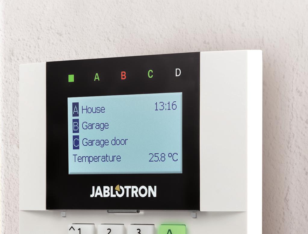
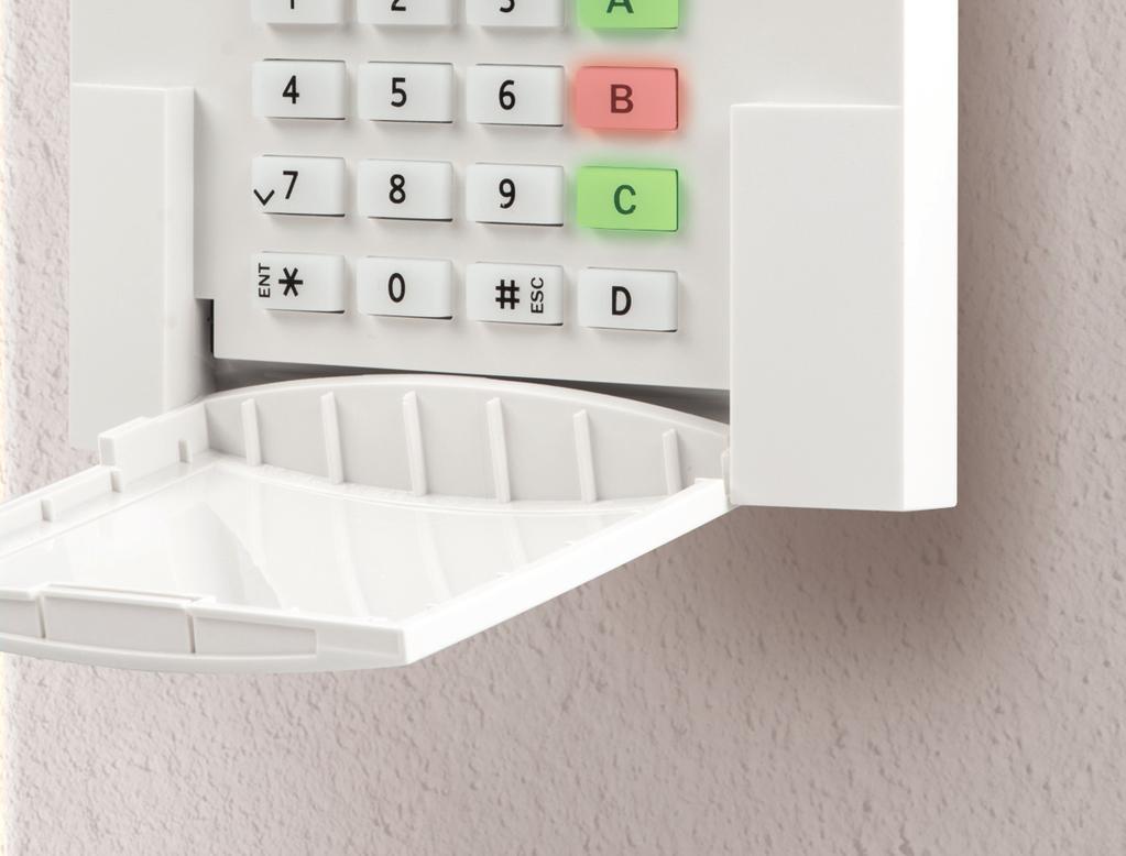
7 6 2. OPERATING THE JABLOTRON 100 SYSTEM Ways of operating the JA-100K control panel: On-site: o System keypad o System keyfob o Via a computer using a USB cable and the J-Link software Remotely: o MyJABLOTRON smart phone application o Via a computer using MyJABLOTRON web interface o Mobile phone via SMS o Mobile phone - using the voice menu o Computer - via the internet using the J-Link software o Dialling-in from an authorized telephone number (only for operating programmable outputs). WARNING: Remote control may be limited depending on the range of security and the selected System profile. 2.2 USING THE SYSTEM KEYPAD SYSTEM INDICATOR STATUS INDICATORS A, B,C, D LCD DISPLAY THE KEYPAD AND THE RFID READER FUNCTION BUTTONS A, B, C, D


.")
8 2. OPERATING THE JABLOTRON 100 SYSTEM 7 The JABLOTRON 100 system may be controlled by system keypads which let you not just control but also display statuses of individual sections. Statuses of individual sections are indicated by status indicators A, B, C, D above the LCD display and by the functions buttons. The control panel can be operated directly (setting or unsetting the alarm and other automation functions) using function buttons on the keypad. The function buttons and the status indicators A, B, C, D are colourfully backlit in order to clearly indicate the section status. GREEN Unset YELLOW Partially Unset RED Set Authorization Authorization can be done by entering an access code on the keypad or using an RFID card/tag assigned to a particular user. Each user can have one code and one RFID chip (a card or a tag). The control panel supports RFID chips compatible with 125 khz EM Unique technology. If higher security is required the alarm system can be set up to use Double authorization using RFID chips and codes (an optional function). If the user wants to control multiple sections simultaneously, he must authorize himself and then press function buttons of the particular sections subsequently. This way the user can unset all sections (for example the house and the garage) within one single authorization.
9 8 2. OPERATING THE JABLOTRON 100 SYSTEM Structure and description of the internal LCD keypad menu Cancel warning indication Allows you to cancel alarm/unsuccessful setting indication in all sections to which the user has access rights Section Control Allows you to control the system s sections to which the user has access rights and are enabled in the internal settings. Event memory Displays a detailed list of the event memory. Setting prevented Shows a list of triggered detectors preventing setting the system, provided this option is activated in the control panel configuration. Administrator or User authorization by the code or RFID tag/card Bypassed detectors Displays a list of all blocked detectors in sections to which a user has access rights. Faults in system Displays a list of all detectors indicating system faults from sections to which the user has access rights. System status Shows system status (list of triggered detectors, triggered tamper contacts, low batteries, bypassing, etc.). Settings Allows editing of users and devices (only when USB is disconnected). Display setting Allows adjustment of keypad backlight intensity and display contrast.
10 2. OPERATING THE JABLOTRON 100 SYSTEM ALARM SETTING 1. Authorize yourself using the keypad. Function buttons A, B, C, D will light up and the system indicator starts flashing green. 2. Press the function button to set a particular section. It is possible to set more sections subsequently. The delay between sections selection must not be longer than 2 seconds. 3. The command is executed and the keypad acoustically indicates the exit delay. The section is set now, only the detectors with a Delayed Zone reaction provide time to leave the guarded area during the Exit delay. The status indicator and a function button of the set section will turn red. While setting the alarm, if any detector is triggered (e.g. an open window) the system will react (based on the system configuration) in one of the following ways: o The control panel will set itself. Triggered detectors will be blocked automatically.*) o The system will optically indicate triggered detectors with a function button flashing red for 8 seconds and the control panel will set automatically once this period has expired (triggered detectors will be blocked). *) o Setting the section with triggered detectors is also possible by pressing the function button repeatedly. The user must confirm an intention to set the section with a triggered detector (e.g. an opened window). Otherwise the system will not set. o A triggered detector will prevent the section from being set. This status is optically indicated by a function button flashing red. The detector preventing setting will be shown on the LCD display menu. *) WARNING: Options a) and b) are not supported by EN 50131, gr.2 (selected control panel system profile). If a detector with the Instant zone alarm reaction is triggered during an exit delay or if a detector with the Delayed zone alarm reaction stays triggered after the exit delay has expired, then the control panel will unset again. Unsuccessful setting is indicated by a system indicator flashing yellow, reported to the ARC and indicated by an external siren (applies to the security Grade 2). If the control panel is configured to be set without authorization then it is not necessary to authorize yourself. All you have to do is press a function button of a particular section. It is also possible to configure the control panel to be set simply by authorization. WARNING: Setting without authorization automatically lowers the maximum security level to Grade 1. Consider all possible risks related to using this function. Consult the installation with a project consultant or a service technician in order to program the desired behaviour of the alarm system.
11 10 2. OPERATING THE JABLOTRON 100 SYSTEM ALARM UNSETTING 1. When you enter the building (triggering a detector with a Delayed zone reaction), the system starts indicating an entrance delay with a continuous tone, the system indicator and a function button, both flashing red, of the section in which the delayed entrance has been triggered. 2. Authorize yourself using the keypad the system indicator will start flashing green. 3. Press the function buttons of the sections you want to unset. 4. The command is executed. The function buttons and the system indicator turn green to indicate unset sections. Note: If the Unset section by authorization only during entrance delay parameter is enabled, then mere authorization will unset a section where the entrance delayed has been triggered. This option should be used with caution when using multiple sections. Consult the installation with a service technician in order to program the desired behaviour of the system PARTIAL ALARM SETTING WARNING: This is an additional function of the alarm system. The system can also be configured to be partially set which allows guarding only by certain detectors in a section. Example: At night, it is possible to set the door and window detectors only, while selected motion detectors will not trigger the alarm when somebody moves inside the section. 1. Authorize yourself using the keypad (enter a code or hold an RFID card or tag up to the reader). The system indicator button will start flashing green. 2. Press the function button of the selected section. 3. The command is executed and the function button turns permanently yellow to indicate a partially set section.
12 2. OPERATING THE JABLOTRON 100 SYSTEM 11 To set the entire premises in which partial setting is enabled, hold down the button to set the control panel for 2 seconds or press it twice. After the button is pressed once it shows continuous yellow light, after it is pressed a second time it shows continuous red light. If the system is partially set already the function button shows a continuous yellow light the entire system can be fully set by authorization and pressing the yellow button for a longer time. Once the button is pressed, the system will be fully set and the button turns red. Partial setting can be configured in a way that authorization is not required. In order to unset the control panel when it is partially set, press the yellow button. The control panel will unset and the button turns green DURESS ACCESS CONTROL Provides unsetting of the control panel in a special mode. The system seemingly unsets, however it triggers a silent panic alarm, which is reported to selected users (including ARC). Unsetting under duress is executed by adding 1 to the last number in a valid code. Contact your service technician if you want to use this feature. Example: Valid code: 9999 Code for unsetting under duress: TERMINATING A TRIGGERED ALARM 1. Authorize yourself using the keypad (enter a code or hold a tag up to the reader). 2. Press the function button of the section in which the alarm has been triggered. 3. Unsetting is finished and sirens are silenced. Rapidly alternately flashing function buttons (green/red) and the status indicators indicate the alarm memory. A triggered alarm in progress is indicated by the status indicator and the function button rapidly flashing red. You need to authorize yourself using the keypad in order to terminate the alarm. The section remains set, a rapidly flashing red function button indicates the alarm memory. Indication will continue flashing even after the system has been unset. WARNING: If the alarm memory indication was activated during your absence, always enter the building with caution, search for the cause of the alarm in the event history and be very careful when checking the premises or wait until the security agency arrives (provided your system is connected to an Alarm Receiving Centre). The alarm memory indication remains on until the system is set once again. Alternatively, it can be also cancelled from the keypad menu: Main menu Cancel warning indication.


.")

13 12 2. OPERATING THE JABLOTRON 100 SYSTEM Indication of a triggered tamper alarm can be terminated only by a Service technician and Administrator. Note: When using the Default system profile, it is possible to select a particular action by pressing a function button first and then confirm it by authorization using the keypad. Terminating an alarm using a remote control will also unset the corresponding section SECTION CONTROL BY AUTHORIZATION The service technician can configure the control panel to be controlled just by authorization. This way the status of all sections can change by authorization on a keypad (by typing an access code or using an RFID chip) SECTION CONTROL FROM THE KEYPAD S MENU Control from the keypad menu: o Authorize yourself using a valid code or an RFID chip o Enter the menu by pressing ENTER o Section Control ENTER o Select the desired section using arrows o Pressing ENTER repeatedly will change between section statuses (partially set / set / unset) Partial setting: Fully set: 1 1 o Press ESC to exit the menu. 2.3 OPERATING THE CONTROL PANEL WITH A KEYFOB Keyfobs must be enrolled into the control panel by the installer. In order to control the alarm system, keyfobs must be linked to specific users, which will ensure their identification and prevent sending SMS notifications to the user who is interacting with the control panel at the moment (if notification parameters are set up in this way). The keyfobs can provide either bi-directional communication, confirming the execution of a command with a coloured indicator light, or one-way without any confirmation. Keyfobs control and indicate battery status and are equipped with optical and acoustic indication. Bi-directional keyfob The button functions are differentiated by lock icons. The closed lock icon sets programmed sections; the opened lock icon unsets them. Correct command execution is confirmed by an LED light; unsetting green, setting red. A communication fault (out of the control panel s range) is indicated by a yellow LED light flashing once. The buttons with symbols of full and empty circles can control another section. Buttons of the keyfob can also be configured to control PG outputs in different modes: the first button switches on, the second switches off, each button can have an individual function when impulse or copy functions are used. For more functions, it is possible to press two buttons at the same time. This way a 4-button keyfob
. If the system is configured to Set after confirmation (chapter 2.1.1) the detector will indicate unsuccessful setting with a green LED light if a device is triggered.")
14 2. OPERATING THE JABLOTRON 100 SYSTEM 13 can have up to 6 individual functions. For example, to control an assigned section, one PG status output (e.g. turn the lights on and off), alternatively two impulse PG outputs (e.g. a garage door and door lock). If the system is configured to Set after confirmation (chapter 2.1.1) the detector will indicate unsuccessful setting with a green LED light if a device is triggered. It is necessary to confirm setting by pressing the lock button again. A set section will be confirmed by a red LED light. The keyfob buttons can be blocked to prevent accidental pressing (child safety lock). A command will be sent out when a button is pressed repeatedly. A low battery is indicated acoustically (with 3 beeps) and optically with a yellow flashing LED after pressing a button. For more information, consult configuration of the remote control with your service technician. More detailed information is available in manuals to particular keyfobs. One-way keyfobs One-way keyfobs send a signal every time a button is pressed without receiving feedback from the control panel. Sending a signal is confirmed only by a short flash of the red LED light and alternatively with a beep. The button functions are with identical with the bi-directional keyfobs. A low battery is indicated by a red LED light and acoustically (3 fast beeps). 2.4 OPERATING THE SYSTEM USING A COMPUTER AND A USB CABLE (J-LINK) The JABLOTRON 100 can be operated locally or remotely (see chapter 2.9) using a computer and installed J-Link software, which can be used for user management (add/remove users, change their level of authorization, phone numbers, codes, card/tags, etc.). J-Link software is available for local connection with a control panel. It is located on the storage drive of the security system (FLEXI_CFG/j-link), which will appear after the control panel is connected to a PC via USB. It is possible to set / unset the system using icons on the bottom bar of the software or with the Status buttons in the Section tab. WARNING: When the system is controlled via PC, it doesn t check for triggered devices while setting. This may lead to setting with a triggered device. Be careful when you control the system this way! WARNING: The J-Link software is available the for Windows operating system only. 2.5 OPERATING THE CONTROL PANEL USING THE VOICE MENU If there is a GSM or a PSTN communicator installed in the control panel, the system can be controlled from a mobile phone or land line through a simple voice menu, which guides the user through a series of options in the preconfigured language. To access the voice menu, you just dial the control panel s phone number. Access to the voice menu can be enabled either to all telephone numbers without restrictions or only to


15 14 2. OPERATING THE JABLOTRON 100 SYSTEM authorized phone numbers stored in the control panel. Depending on the configuration, authorization by entering a valid code on a phone keypad may be required. When the user enters the menu, the system will give an update of the current status of all sections assigned to the user. The caller then can control these sections, either individually or collectively, using phone keypad and available menu options. WARNING: It is necessary to use this function with caution. Remote setting and unsetting may cause unwanted alarms or prevent setting when there are other people still present in the building. By default, the system is set up to answer incoming calls after three rings (approximately 15 seconds). 2.6 OPERATING THE SYSTEM VIA THE MyJABLOTRON WEB INTERFACE The JABLOTRON 100 system can be easily and conveniently operated using your computer and the internet via the MyJABLOTRON web interface, which is accessible from For more information about this web interface, please see the chapter 6 below. MyJABLOTRON - PROFI Version Depending on your country or region, a web account in MyJABLOTRON can be set up by an authorized JABLOTRON partner. The login name is the user s address. The password for the first login will be sent to this address. The password can be changed at any time in the user settings. Once logged into the account, MyJABLOTRON will show all active devices that can be monitored or controlled. The Overview menu includes Section, Automation (PG) tabs. Depending on the type of detectors used, the menu may also include tabs like Thermostats and thermometers, Meters History and Gallery. Tabs: o Sections enables you to view and operate all sections in the system by clicking on the lock symbol. You will be asked you to enter an authorization code upon the first request to control the system. While you are logged in, subsequent actions will not require repeated authorization. o Automation (PG) enables you to view and control all programmable system outputs by clicking on the OFF/ON symbol. o Thermostats and thermometers - allows you to view the current temperatures and history graphs. Depending on the control panel s configuration, it is possible to change thermostat modes or temperature. o Meters an overview of all installed electricity meters, alternatively gas or water meters. It displays measured values or history graphs. o History displays control panel s event history including thumbnails of photos taken by camera detectors. o Gallery enables you to take snapshots with any installed camera motion detectors, or look at past photos taken with these detectors. The bottom of the home page has an overview of the most recent system events. MyJABLOTRON offers free notifications (via SMS, , or PUSH notifications) for selected system section events, programmable outputs, thermometers or meters. These notifications can be set up in the Settings menu.

 of the new user.")


 o The photo gallery and taking photos by request with camera detectors are not available o Thermometers, electricity meters")

, the alarm system can be monitored and")
16 2. OPERATING THE JABLOTRON 100 SYSTEM 15 Each system can have only one main user with Administrator rights (owner). This user has the right to share a whole building, selected sections, PG outputs, camera detectors, thermometers and other devices with other users whose MyJABLOTRON accounts will be created automatically after the system sharing is configured. If a user already has a MyJABLOTRON account, the shared installation will appear in the user s dashboard as another active device. Notification of the shared access will be sent, along with the password, to the address (login name) of the new user. MyJABLOTRON - LITE Version Depending on your country (or region) customers may be able to create an account and/or services in the LITE version of MyJABLOTRON web app. The LITE service is limited in functionality and minimizes demands for data transfer. LITE is based on the PROFI version with the following modifications: The LITE version in comparison with PROFI version: o Doesn t maintain a constant connection with a control panel o Establishing connection takes approx. 1 minute o The current status appears after successful connection o Controlling the system (sections or PG outputs) is possible after successful connection o The event history is not available o The system doesn t send event notifications (SMS, , PUSH notifications) o The photo gallery and taking photos by request with camera detectors are not available o Thermometers, electricity meters and other supported automation devices are not displayed A password will be sent to the user s address, which also serves as a login name. The password can be changed at any time in the settings. Once logged into the account, the system shows all active devices that can be monitored or controlled, depending on the version of MyJABLOTRON used to register them (PROFI or LITE). 2.7 OPERATING THE CONTROL PANEL USING THE MyJABLOTRON SMARTPHONE APP If the user account is created in the MyJABLOTRON web interface (see previous chapter), the alarm system can be monitored and controlled remotely using MyJABLOTRON app for smart phones running either on Android (ver or higher) or iphone (ver. 9 or later). The application can be downloaded free of charge after logging into MyJABLOTRON, or from Google play, App Store and others. Usernames and login credentials for the MyJABLOTRON smartphone app are identical to those for the MyJABLOTRON web interface. 2.8 OPERATING THE CONTROL PANEL BY SMS If there is a GSM installed in the control panel then it is possible to use SMS commands to control Individual sections and programmable outputs just like the keypad function buttons. The form of text message to operate the system is: CODE_COMMAND. The actual commands are predefined (SET/UNSET) with an additional numeric parameter which identifies a specific section. One SMS can control multiple sections at the same time. In this case, added numbers in the command define sections.


 by installing the J-Link software on your computer which can also manage users (change codes, cards/tags, and phone numbers).")
 and the telephone number of its SIM card (if used) is required to connect to the system remotely the first time.")
.")

17 16 2. OPERATING THE JABLOTRON 100 SYSTEM Example of an SMS command used to set sections 2 and 4. The underscore _ sign stands for a space between words. CODE_ SET_2_4 The commands to control the programmable outputs can be programmed by a service technician. For example, you may choose SHUTTERS DOWN as your command to close the shutters on your windows. It is also possible to configure the system not to require a code before a command. In such case the command is automatically identified when the system recognizes the user s phone number from which the SMS was sent. WARNING: It is necessary to use this function with caution. Remote setting and unsetting may cause unwanted alarms or prevent setting when there are other people still present in the building. 2.9 OPERATING THE SYSTEM REMOTELY USING A COMPUTER (J-LINK) The JABLOTRON 100 system can be operated both remotely and locally onsite (see chapter 2.3) by installing the J-Link software on your computer which can also manage users (change codes, cards/tags, and phone numbers). To operate the system remotely, the program must be downloaded from the Downloads section of the website or it can be found in the control panel s SD card. The registration code of the security system (a 14 digit code) and the telephone number of its SIM card (if used) is required to connect to the system remotely the first time. Remote access is initiated by clicking on the Internet button in the main menu. When the connection has been established, the control panel can be controlled the same way as if we used connection via a USB cable (see the chapter 2.4). It is possible to set / unset the system using icons of sections on the lower bar of the software or with the Status buttons in the Section tab. WARNING: When the system is controlled via PC, it will not prevent setting with a triggered device. Be careful when you control the system this way! WARNING: The J-Link software is available the Windows operating system only PG OUTPUTS CONTROL PG output control is intended for non-alarm functions related to home automation. It is necessary to consider whether they will be used for status indication or controlling electronic locks KEYPAD FUNCTION BUTTONS A PG output switches on by pressing a function button (A, B, C, D) and switches off by pressing the button again. If the output is configured as an impulse output, it will switch off according to the preset time. Whether authorization is or is not demanded depends on the system configuration.
18 2. OPERATING THE JABLOTRON 100 SYSTEM USER KEYPAD AUTHORIZATION It is possible to activate a PG output by user authorization (entering a code or using an RIFD tag). The PG output must be configured to activate from a designated keypad REMOTE CONTROL By pressing an assigned remote control button DIALLING-IN Each telephone number stored in the control panel (one user can have one telephone number) can control a PG output just by dialling-in (i.e. without establishing a call). Dialling-in consists of dialling the phone number of the SIM card used in the security system and hanging up before the system answers the call. By default, the system will answer the call after the third ring (approximately 15 seconds). WARNING: It is possible to control to the PG output only if the GSM or PSTN communicator installed in the control panel SMS MESSAGE Sending an SMS can switch on/off a particular PG. Whether authorization is or is not demanded depends on the system configuration. Example: CODE_CONFIGURED TEXT ( _ character = space) WARNING: It is possible to control to the PG output only if the GSM or PSTN communicator installed in the control panel MyJABLOTRON By clicking on the ON/OFF button in the Automation tab. 3. BLOCKING IN THE SYSTEM 3.1 BLOCKING USERS Any user can be temporarily blocked (e.g. when a user loses a card/tag or his access code is revealed). When user s access is blocked the user access code or a card/tag will no longer be accepted by the control panel. The blocked user will also not receive any text message alerts or voice reports to a mobile phone. Only the system administrator or service technician can block a user. One method of taking away access rights is by choosing Settings / Users / User / Bypass and selecting Yes on the LCD keypad. Another option is to locally or remotely block a user through the J-Link software by clicking on the user in the Settings / Users / User blocking column. A blocked (disabled) user will be marked with a red circle until the blocking is removed.
19 18 3. BLOCKING IN THE SYSTEM 3.2 BLOCKING DETECTORS A detector can be temporarily blocked in a similar way a user can be blocked. A detector is blocked when its activation is temporarily not desirable (for example a motion detector in a room with a pet or disable a siren sounding). Only the alarm function is deactivated however the system still performs diagnostics of tamper contacts and sends tamper alarm and service events. Only the system administrator or service technician can block a detector. It can be achieved by choosing Settings / Devices / Bypass and selecting Yes on the LCD keypad. Another option is to use the J-Link software by clicking on the detector in the Settings / Diagnostics / Disabled column. A blocked detector is marked with a yellow circle until it is turned back on using the same procedure. A device can be also blocked from MyJABLOTRON smartphone app in the More/Devices roll up menu. WARNING: This function is limited by the selected System profile of the control panel. Always consult blocking detectors with your service technician. If the premises are guarded by a security agency, consult them as well. 3.3 DISABLING CALENDARS To temporarily disable automated scheduled events in the system, the timers can be turned off. Disabling a scheduled event (e.g. unsetting the system from night guarding at a predetermined time) stops the execution of that event (e.g. while on vacation). A timer can be turned off locally or remotely through the J-Link program by clicking on the section in the Settings / Calendar / Blocked column. A disabled timer is marked with a red circle until it is turned back on using the same procedure. 4. CONTROL PANEL USER SETTINGS 4.1 CHANGING USER ACCESS CODE Only the system administrator and the service technician can change the security codes. These changes are done after authorization by selecting Settings / Users / User / Code. To enter a new code, you must enter edit mode by pressing Enter (the line will start to flash). Now you can edit the code. The new code will be confirmed by pressing Enter again. After the changes are complete the change must be saved by selecting Save when the control panel prompts with Save Settings? Codes can be also changed in the MyJABLOTRON smartphone app in the More/Change the user code roll up menu or via the J-Link SW. 4.2 CHANGING, DELETING OR ADDING AN RFID CARD/TAG Only the administrator and the service technician can add, change or delete RFID tags or cards from the LCD menu on the keypad or via the J-Link SW. These changes are done after authorization by selecting Settings / Users / User / Access card. To enter a new RFID card/tag, you must enter edit mode by pressing Enter (access card line will start to flash). Then the RFID card/tag must be placed on to the reader (in front of keys) or the serial number under a bar code must be entered manually. After confirming by pressing Enter again, the RFID card/tag is added. To delete an access card enter 0 into the serial number field. After the changes are complete the change must be saved by selecting Save when the control panel prompts with Save Settings?
20 4. CONTROL PANEL USER SETTINGS CHANGING A USERNAME OR PHONE NUMBER Only the administrator and the service technician can add, change or delete telephone numbers or change names of the users from the LCD menu on the keypad or via the J-Link SW. This can be done after authorization by selecting Settings / Users / User / Phone. The user must be in edit mode to make changes. This is done by pressing Enter. After making the changes, they must be confirmed by pressing Enter again. To delete a phone number enter 0 into the phone number field. After the changes are complete the change must be saved by selecting Save when the system prompts with Save Settings? 4.4 ADDING/ DELETING A USER Only the service technician or the administrator can add new users to the system (or delete them). New users can be added to the system (or deleted from it) only via the F-Link (the service technician) or J-Link software (administrator). When creating new users, it is necessary to assign them with access permissions (rights) to individual sections and programmable outputs control with required authorization. 4.5 CALENDAR EVENTS SET UP It is possible to configure up to 10 calendar events (unsetting/setting/partial setting, controlling or blocking PG outputs). A single calendar event may combine several actions at the same time. For example, you can Set selected sections, switch on a PG output and block another PG, all at once. Timers can be set up via J-Link in the Calendar tab. 5. EVENT HISTORY The security system stores all performed operations and events (setting, unsetting, alarms, faults, messages sent to users and ARCs) in the micro SD card in the system s control panel. Each entry includes the date, time (start and end), and source (cause / origin) of the event The different ways of browsing the system s event history: 5.1 USING THE LCD KEYPAD Accessing the event history using the keypad requires user authorization. Once authorized, the available options (based on user permissions) are displayed by choosing Event Memory. Records can be viewed from the most recent to the oldest using arrows. 5.2 USING J-LINK AND A COMPUTER The system memory can be browsed using the J-Link program. Events can be viewed in small (about 1,200 events) or larger (about 4,000 events) batches. The events can be filtered, colour-coded for easier orientation, or saved into a file. For more information please see the J-Link manual. Warning: The J-Link software is available the Windows operating system only.
 All system events can be viewed using after logging in the MyJABLOTRON web interface or")


21 20 5. EVENT HISTORY 5.3 LOGGING INTO MYJABLOTRON (WEB/THE SMARTPHONE APP) All system events can be viewed using after logging in the MyJABLOTRON web interface or the smartphone app. The account shows history in a range which corresponds with the user s permissions. 6. WHAT IS MYJABLOTRON? MyJABLOTRON is a unique service which provides on-line access to JABLOTRON devices. It is intended for the end users and allows them to monitor and control the system. MYJABLOTRON ALLOWS USERS TO: o View the current system status. o Set/unset the entire system or part of it. o Control programmable outputs. o View the event history. o Send reports to selected users via SMS, and PUSH notifications o Capture images from verification detectors and browse through them in the Photo gallery tab or directly in Recent events o Monitor current temperature or energy consumption, including a history overview on a graphic chart. o And other useful features. 7. PERIODICAL MAINTENANCE It is necessary to have regular and timely maintenance checks performed in order to secure reliable functioning of the system. Most of the maintenance is carried out by an installation company at least once a year during periodical maintenance inspections. User maintenance consists of keeping the individual devices clean. Some devices may require regular testing which is always described in the individual manual of such device (e.g. fire detectors).
22 8. TECHNICAL SPECIFICATIONS 21 PARAMETER JA-100K Type of installation Fixed installation Nominal control panel voltage / frequency / fuse ~ 230 V / 50 Hz, T200 ma fuse 250 V 5 x 20 mm ~ 115 V / 60 Hz, T400 ma fuse 250 V 5 x 20 mm Operation voltage range ~ 195 V 250 V ~ 110 V 120 V Electric power / current Max 23 VA / 0.1 A Protection class II. Back-up battery 12 V; 2.6 Ah max. (lead-acid) Low battery voltage (fault indication) 11 V Maximum battery charging time h BUS voltage / max. voltage ripple (red-black) 12,0 13,8 V DC / ± 100 mv Max. continuous consumption from the control panel BUS +RJ 400 ma permanently (1000 ma for 5 12 hours backup (2.6 Ah) LAN OFF: 125 ma consumption of external modules LAN ON: 85 ma consumption of modules Max. number of devices 32 Alarm connection JABLOTRON BUS dedicated wired connection Wireless connection (with JA-111R) unspecified wireless connection, JABLOTRON wireless protocol Alarm system classification Security grade 2 / environmental class according to standards EN , EN , EN , EN , EN , EN , EN environment Indoor operational temperature / humidity -10 C to +40 C, relative humidity 75%, no power Type A primary supply with a charged backup event history approx. 7 million latest events, incl. date and system reaction to communication loss Fault or tamper according to the pre-set BUS - up to 10 wireless communication - in 2 hrs wireless communication - in 20 min block system to be reaction to invalid code entry After 10 wrong code entries a tamper alarm is triggered and according to the selected profile it blocks all control devices for 10 ATS classification Supported ATS classes : SP2 SP 5, DP2 DP3 SPT: type Z Operation type: Pass-Through Built-in LAN: SP2 SP5 (with IP protocol) JA-190Y SP2 SP5 (with IP protocol) JA-190X SP2 (with Contact ID protocol) LAN + JA-190Y DP2 DP3 (with IP protocol) LAN + JA-190X DP2 (with IP / CID ATS transferring protocols JABLO IP, SIA IP, Contact ID, JABLO ATC protection against substitution and data protection JABLOTRON protocol: Proprietary AES encryption with minimum 128 bit key ANSI SIA DC protocol with 128 bit AES encryption LAN communicator Ethernet interface CAT 5 (RJ-45) Dimensions 268 x 225 x 83 (mm) Weight 1450 g Basic parameters of the JA-111R module MHz, < 25 mw, GFSK < 80 khz Radio emissions ETSI EN (the JA-111R module) EMC EN , EN 55032, ETSI EN , ETSI EN Electric safety EN Operational conditions ERC REC 70-03, ERC DEC (98) 20 Certification body TREZOR TEST
23 22 8. TECHNICAL SPECIFICATIONS JABLOTRON ALARMS a.s. hereby declares that the JA-100K control panel meets the basic requirements and other relevant provisions of the EU directive no.2014/35/eu, 2014/30/EU and 2011/65/EU. You will find the original Declaration of Conformity at section Downloads. Note: Although this product does not contain any harmful materials we suggest you return the product to the dealer or directly to the producer after use. 9. GLOSSARY OF TERMS BUS / Wireless Devices: The main hub of the security system is its control panel. It can communicate with all devices in two ways: using the BUS, i.e. using data cables within the guarded premises or part thereof; or wirelessly using radio communication. BUS devices are powered by the control panel. Wireless devices require batteries whose longevity depends on intensity of use. Some of the wireless devices are supplied by 230V from the electric grid (see the manual of the particular device). RFID Card / Tag The RFID card/tag allows the user to operate the system and is used for contactless authorization by simply placing the card/tag on to the keypad reader. It replaces or complements numerical code entries. The RFID card can be carried in a wallet which can be placed on the keypad for authorization. The RFID tag can be attached to a key ring. Section The alarm system can be divided into several smaller, independently functioning parts, called sections. Each section can have its assigned detectors, keypads, as well as sirens, users and their telephone numbers. There can be up to 4 sections per system. Programmable Outputs PG The security system can be used to switch on/off or control other electrical devices or appliances. This is done using programmable outputs that can be controlled by the user (an SMS message, using the keypad) or can be automated based on the system status (following the system status, alarm status, fault, etc.). Home Automation In addition to providing an intrusion alarm system, the JA-100 offers a number of other features. Among the most popular functions are: electrical door locks, automated light switches using motion detectors, and the remote control of appliances (heating, garage doors, gates, entry barriers, etc.). Panic Alarm When a user is in danger and in need of urgent assistance, the panic alarm can be triggered. The panic alarm can be set up as a designated function button on the keypad, a special code, a panic button, or as a specific combination of buttons on a keyfob. If connected to a security centre, triggering the panic alarm creates an immediate response (vehicle dispatch) that cannot be cancelled by phone. Security Centre, ARC An Alarm Receiving Centre, a continuously manned security agency (24/7/365), is able to immediately react to information received from the guarded premises and respond with an appropriate action or proceed according to internal rules. MNX28101
DESCRIPTION OF KEYPAD (Access module with segments)
") DESCRIPTION OF KEYPAD (Access module with segments) For the most convenient control and status indication the JABLOTRON 100 system offers various types of access modules. Controlling (setting, unsetting
DESCRIPTION OF KEYPAD (Access module with segments) For the most convenient control and status indication the JABLOTRON 100 system offers various types of access modules. Controlling (setting, unsetting
JA-101K(-LAN)(-LAN3G) and JA-106K(-3G) Security System Control Panels
(-LAN3G) and JA-106K(-3G) Security System Control Panels") Security System Control Panels A control panel is a fundamental part of the JABLOTRON 100 series alarm system and is designed to protect small, medium or large premises and complies with security grade
Security System Control Panels A control panel is a fundamental part of the JABLOTRON 100 series alarm system and is designed to protect small, medium or large premises and complies with security grade
Contents Description... 3 AZOR kit contents... 4 Installation... 7 Control Settings System extension Other information...
 MLO51205-1 - Contents Description... 3 AZOR kit contents... 4 AZ-10K GSM control unit... 4 AZ-10D RFID tag reader... 5 AZ-10M door-opening detector... 5 AZ-10P motion detector... 6 Installation... 7 Door-opening
D3D Wi-Fi GSM Smart Alarm System -User Manual
 D3D Wi-Fi GSM Smart Alarm System -User Manual D3D Wi-Fi / GSM Smart Alarm system (Model : D10). Please read all instructions carefully & follow steps for easy home installation. 1 P a g e D3D Wi-Fi / GSM
Wireless Alarm System Extended User Guide. Alarm Panel Time 10:09 c
 Wireless Alarm System Extended User Guide Alarm Panel Time 10:09 c Contents Introduction 5 ProControl+ 7 Setting Devices 8 The Wireless Panel Keypad and Additional Keypads 8 Proximity Tag Readers 8 Internal
EURO 46 V10 User Manual
 EURO 46 V10 User Manual PD6662:2010+IA501:2015 EN50131-1:2008+A1:2009 EN50131-3:2009 Security Grade (SG) 3 - Large Security Grade (SG) 2 - Small Environmental Class (EC) II Software Version >10 RINS1943-1
JA-101K and JA-106K alarm system control panel
 JA-101K and JA-106K alarm system control panel Warning: The JABLOTRON 100 series alarm system should be installed exclusively by a trained technician with a valid certificate issued by an authorized Jablotron
A secure and smart firm. The JABLOTRON 100 security system with its unique MyJABLOTRON application
 A secure and smart firm The JABLOTRON 100 security system with its unique MyJABLOTRON application Security and control of your firm in one solution The JABLOTRON 100 is a versatile system for the security,
Smart GSM/GPS car alarms
 Smart GSM/GPS car alarms Control CA-1802 and CA-1803 Athos Guarding Communication User manual Accessories 4453 - Jablotron - Manuál Athos - EN.indd 1 18.5.2010 9:25:34 Contents 1 Car alarm control... 3
1. Introduction. 2. Product overview
 1. Introduction The AG400011 GSM Alarm panel is a control panel that is compatible with other H-net security devices from Everspring, such as wireless sensors, remote keyfobs, tags, and keypad. With this
JA-63 Profi User manual
 JA-63 Profi User manual Contents: 1 Limited warranty... 2 2 Indicators... 3 3 Controlling the system... 4 3.1 Arming... 5 3.2 Disarming... 6 3.3 Panic Alarm... 6 3.4 To stop ALARM... 6 3.5 Home arming...
Contents. Glossary
 Contents Glossary ------------------------------------------------------------------------------------------------------ 6 1. Introduction to the IDS 1632 -------------------------------------------------------------
Ref. 1067/024 Ref. 1067/032A Ref. 1067/052A
 DS1067-062C Mod. 1067 LBT20063 REMOTE CONTROLLABLE ALARM CONTROL PANELS Ref. 1067/024 Ref. 1067/032A Ref. 1067/052A USER MANUAL TABLE OF CONTENTS INTRODUCTION... 6 1 CONTROL DEVICES... 7 1.1 1067/022 keypad
Galaxy Flex V3. User Guide. Honeywell Security. This user manual is located at
 Galaxy Flex V3 User Guide Honeywell Security This user manual is located at www.eaglesecuritysolutions.co.uk Contents Introduction... 5 Controlling your alarm system... 6 Users... 6 Panel control... 6
Ref.1067/032 Ref.1067/042
 DS1067-033A Mod. 1067 LBT8631 BUS CONTROL PANEL 8/32 INPUTS Ref.1067/032 Ref.1067/042 USER MANUAL TABLE OF CONTENTS 1 PREFACE... 5 2 COMMAND DEVICES... 6 2.1 1067/021 DISPLAY KEYPAD... 6 2.2 ELECTRONIC
Profile. For a better understanding of this product, please read this user manual thoroughly before using it.
 Intelligent GSM Auto-Dial Alarm System User s Manual Profile For a better understanding of this product, please read this user manual thoroughly before using it. Contents Function Introduction (3) Alarm
NextGen Home Security. Quick Reference Guide
 TM NextGen Home Security Quick Reference Guide Fire Auxiliary Panic (not active) Stay Away Chime Reset Bypass To view the full user manual, go to www.bellaliant.net/homesecurity and select Support. Arming
Operation Manual Fighter ProVision Software. Version: 0.0 Revision: 1
 Operation Manual Fighter ProVision Software Version: 0.0 Revision: 1 TABLE OF CONTENTS 1. Introduction 5 2. Software Installation 5 3. PC Users 6 3.1 Introduction 6 3.2 Default Code 6 3.3 Edit PC User
Summary of Keypad Main User Commands
 User Manual Summary of Keypad Main User Commands Full Set Code > Part Set Code > System Unset Silence an Alarm Partition Full Set Partition Part Set Code> Code> Code > > Partition No. > Code > > Partition
SMART HOME SECURITY. Dual Network Communicating Alarm System with RFID INVINCIBLE. Instruction Manual. Customer Helpline
 SMART HOME SECURITY Dual Network Communicating Alarm System with RFID INVINCIBLE Instruction Manual Customer Helpline 045 57 500 Table of Contents Kit Contents ---------------------------------------------------------------------
System. For a better understanding of this product, please read this user manual thoroughly before using it.
 GSM Alarm System User s Manual For a better understanding of this product, please read this user manual thoroughly before using it. Chapter 1. Features Chapter 2. Control Panel Introduction Chapter 3.
3 User s settings. 3.3 Internal clock setting
 2.9 Subsystem arming In a large building a sub control panel can be enrolled to the JA-63. The subsystem reports all alarms and failures to the main system. The installer can program if the systems will
EURO 46 APP. User Manual. Connect to your home or business from anywhere in the world. Software version 2.1 RINS1840-2
 EURO 46 APP User Manual Connect to your home or business from anywhere in the world. Software version 2.1 RINS1840-2 Contents Two Way Wireless High Security 3 User Friendly Keyfobs 4 User Automation Outputs
Ontech GSM 9040/50. Reference Manual English -1 -
 Ontech GSM 9040/50 Reference Manual English -1 - Content Welcome... 5 This manual... 5 Text styles... 5 Support... 5 Disclaimer... 5 Overview... 6 Accessories... 6 External temperature sensor 9901... 7
Security designed for your lifestyle
 Security designed for your lifestyle The Paradox Insight : The Big Picture A single CAT5 or higher cable can be used to wire a single HD77 camera. Camera Detector Module HD 720p camera Quad PIR with auto
With Magictrl, you can control MatiGard anytime & anywhere via your smartphone, even without data network.
 MatiGard User Guide 02 Menu Feature-------------------------------------------------------------- 05 Overviews---------------------------------------------------------- 07 Read Before Using-----------------------------------------------
Watchguard WGAP864 User Manual
 Watchguard WGAP864 User Manual v1.0 Issued September 2016 1 2 Table of Contents Glossary... 5 1. Introduction to your Watchguard WGAP864... 6 2. Before Operating your Alarm System... 6 3. Understanding
Intelligent Wireless GSM Alarm System
 Intelligent Wireless GSM Alarm System 00M2K User s Manual Profile For a better understanding of this product, please read this user manual thoroughly before using it. Contents [Function Instruction] [Alarm
your silent and loyal servant
 Easy installation, simple programming! your silent and loyal servant The GD-04 is a GSM remote controller-sensor. It sends SMSes, calls - switches on/off and guards. DAViD cannot speak but is understood
GSM Alarm System. User s Manual. Profile. MOBILE CALL GSM Alarm System
 MOBILE CALL GSM Alarm System GSM Alarm System System disarmed 11/26/2013 User s Manual Profile For a better understanding of this product, please read this user manual thoroughly before using it. CONTENTS
IQ PANEL USER GUIDE SMARTHOME.
 IQ PANEL USER GUIDE SECURITY & SMARTHOME www.schmidtsecurity.com USING YOUR SYSTEM: BASICS Navigation Move from page to page and access information on each page using finger touches, swipes, and scrolling.
BURGLAR ALARM PANEL BS-468
 BURGLAR ALARM PANEL BS-468 Contents 1. Description... 3 2. Instructions for the user... 4 2.1Basic operations... 4 Complete system.... 4 Split system.... 4 2.2 Armed system indication... 5 2.3 Advanced
QUICK USER MANUAL. Alarm Control Panel. The full user manual and other manuals are available on
 Alarm Control Panel Firmware Version 1.09 QUICK USER MANUAL The full user manual and other manuals are available on www.satel.eu versa_ip_us_en 11/17 SATEL sp. z o.o. ul. Budowlanych 66 80-298 Gdańsk POLAND
MOBILE CALL GSM Alarm System User s Manual
 MOBILE CALL GSM Alarm System User s Manual Profile For a better understanding of this product, please read this user manual thoroughly before using it. Contents Function Introduction (3) Alarm Host Diagram
USER S MANUAL. Profile. MOBILE CALL GSM Alarm System
 MOBILE CALL GSM Alarm System USER S MANUAL System disarmed 00/00/00 00:00 ARM STAY CALL 1 2 3 4 5 6 7 8 9 Power Set Signal Alarm SOS ESC 0 ENTER Profile For a better understanding of this product, please
Advisor Advanced Mobile Application User Manual
 Advisor Advanced Mobile Application User Manual Content Warnings and Disclaimers 2 Advanced Mobile 2 Contact information 2 Description 2 Screen navigation 4 Gestures 4 Menu 4 Help navigation 4 Login 5
Training 2 nd part. Agenda for second part
 Training 2 nd part Agenda for second part AZOR GSM mini alarm EYE-02 GSM security camera GD-04 David GSM dialer CA-1803 Athos GSM/GPRS/GPS car alarm system AZOR easy solution GSM mini alarm Azor AZOR -
Alarm Control Panel WIC-16Z4P WIC-5Z2P. Installation & Operation User Manual
 WIC-16Z4P WIC-5Z2P Installation & Operation User Manual Page : 1/34 INDEX # Function Page 1 Abort Current Communication and Clear Reporting Queue (*59) 13 2 Abort Current Communications (*59) 10 3 Account
Power Wave LCD Keypads. Users Operating and Programming Guide Version 2.00
 Power Wave LCD Keypads CR-16S CR-16M Users Operating and Programming Guide Version 2.00 P/N 7102265 Rev. C N.A May 2003 Contents Introduction...4 Meet the PowerWave Alarm Control System... 4 Typical Alarm
GSM RFID VOICE Alarm System
 GSM RFID VOICE Alarm System User s Manual For a better understanding of this product, please read this user manual thoroughly before using it. CONTENTS [Function Instruction] [Control Panel] Control Panel
Control Panel. Operators Manual TO SUIT AS216 KEYPAD. AS216-OM-6.2. Advanced Digital Controls
 Control Panel Operators Manual TO SUIT AS216 KEYPAD AS216-OM-6.2 Ultra-16 Control Panel AS216 OPERATORS MANUAL Copyright 2002 by NZ Ltd Auckland, New Zealand Document Part Number: This document is provided
i on Compact Security System
 i on Compact Security System Administration and User Manual Issue 1 Control unit software version 5.03 Eaton 2017 The information, recommendations, descriptions and safety notations in this document are
Preface. Thank you for purchasing our GSM Security Alarm System ( The System )! The System will keep your home and property safe around the clock.
! The System will keep your home and property safe around the clock.") Preface Thank you for purchasing our GSM Security Alarm System ( The System )! The System will keep your home and property safe around the clock. The GSM Security Alarm ( The Alarm ) adopts the most advanced
Preface Thank you for purchasing our GSM Security Alarm System ( The System )! The System will keep your home and property safe around the clock. The GSM Security Alarm ( The Alarm ) adopts the most advanced
Version 1.03 January-2002 USER S MANUAL
 Version 1.03 January-2002 1 USER S MANUAL 2 Version 1.03 January-2002 System Details CUSTOMER:...... PHONE:... FAX:... INSTALLED BY:...... PHONE:... FAX:... MAINTENANCE & SERVICE:...... PHONE:... FAX:...
User Manual. PIEZO WARNING The Wireless Alarm contains a loud siren, please be aware of this after an activation
 User Manual RINS1902-2 EN50131-1:2006+A1:2009 EN50131-3:2009 EN50131-6:2008 EN50131-5-3:2005+A1:2008 PD6662: 2010+IA:2015 Alarm Panel Time 10:09 c Software Version >10 SMS CHARGES If you re using SMS text
Description Supervised Wireless Technology PRODUCT SPECIFICATION SHEET
 PRODUCT SPECIFICATION SHEET Made by RSI VIDEO TECHNOLOGIES 2200-XLSP February 2012 Description is a Videofied wireless, battery operated security system. The control panel is designed for residential and
Table of Contents. Appendix A Special Characters 31
 Table of Contents Introduction 2 Section 1: General System Operation 3 1.1 Getting to Know Your System... 3 1.2 How to Arm... 4 1.3 Alternate Arming Methods... 5 1.4 Disarming... 6 1.5 Alarm Memory...
Integrated Security Solutions
 Integrated Security Solutions Table of Contents Control Panels 4 Keypads 8 Communication Modules 16 I/O Expanders 20 Door Control 24 Home Automation 25 RF Receivers 26 3 Our integrated security solutions
Ref. 1067/024 Ref. 1067/032A Ref. 1067/052A
 DS1067-064D Mod. 1067 LBT20065 REMOTE CONTROLLABLE ALARM CONTROL PANELS Ref. 1067/024 Ref. 1067/032A Ref. 1067/052A PROGRAMMING MANUAL TABLE OF CONTENTS INTRODUCTION... 7 1 CONTROL DEVICES... 8 1.1 1067/022
SA 2650 Kit User Manual
 SA 2650 Kit User Manual Table of Contents 1. System Installation Planning 1 2. Device Introduction 3 3. Getting Started 6 4. System Default Setting 10 5. Connect2Home Application 11 6. System Information
1. User features of the GSM dialer
 1. User features of the GSM dialer The JA60GSM dialer offers many useful features described in detail below. The installer should properly demonstrate the use of the system to the user after installation
READY TO ARM 1st Floor 2nd Floor
 SECOLINK KM24, KM24A, and KM24G are user-friendly new concept keypads. Large graphic display with helpful texts and backlit keys simplify the use of an alarm system. There are options to customize main
 www.eraeverywhere.com ERA Home Security Straight Road, Short Heath, Willenhall, West Midlands, WV12 5RA email: alarms @ eraeverywhere.com Customer Helpline: 0345 257 2500 Vault_V1.0_3616 IMPORTANT Table
G4S SMARTalarm User Guide
 G4S SMARTalarm User Guide CONGRATULATIONS WITH YOUR NEW SECURITY SYSTEM! We are glad that you have chosen G4S SMARTalarm. G4S is the largest supplier of security solutions in the world. We have invested
Midco SmartHOME Quick Start Guide. Learn how to protect the things that matter most using this Midco SmartHOME instruction guide.
 Midco SmartHOME Quick Start Guide Learn how to protect the things that matter most using this Midco SmartHOME instruction guide. 1 Contents Getting Started.................................................................
A secure and comfortable home. JABLOTRON 100 alarm with the unique MyJABLOTRON application
 A secure and comfortable home JABLOTRON 100 alarm with the unique MyJABLOTRON application Real security and a wide application range Intuitive two-button operation You can make use of the JABLOTRON 100
Using Your. Security System With LED Keypad S5030, S5031, S5032
 Using Your Security System With LED Keypad S5030, S5031, S5032 Contents 1 Overview Your Security System... 1 How Your Security System Works... 2 Your System's Programming... 3 Getting Used to Your System...
MyNice Welcome to your Nice World. The intelligent solution for the integrated management of the alarm system and of the home s automations.
 MyNice Welcome to your Nice World The intelligent solution for the integrated management of the alarm system and of the home s automations. Home page Wi-Fi and GSM status and connected users System name
V1.0. Smart Home Alarm System. User Manual. APP download via QR Code scanning. Please read the manual carefully before using.
 V1.0 Smart Home Alarm System User Manual APP download via QR Code scanning Please read the manual carefully before using. Content FUNCTION PROFILE 2 THE SCHEMATIC GRAPH OF HOST 3 PROCESS OF BOOTING 6 OPERATION
AXI LED USER MANUAL (REV. 1.0)
") Security & Home Automation System AXI LED USER MANUAL (REV. 1.0) CONTENTS PREFACE FEATURES LED KEYPAD OUTLOOK 1.0 LIGHT INDICATION 1 2 4 6 CHAPTER 1: ALARM SYSTEM CONTROL 1.0 USING LED KEYPAD 1.0.1 ARMING
Security & Home Automation System AXI LED USER MANUAL (REV. 1.0) CONTENTS PREFACE FEATURES LED KEYPAD OUTLOOK 1.0 LIGHT INDICATION 1 2 4 6 CHAPTER 1: ALARM SYSTEM CONTROL 1.0 USING LED KEYPAD 1.0.1 ARMING
Total Connect Box. User manual
 Total Connect Box User manual 1 Congratulations on your purchase of the Honeywell Total Connect Box security system. To make the best out of your system we advise you to read this manual carefully. This
CC880/LP880, SC8016. Operators Guide Solution-16, Solution-16 Safecom
 CC880/LP880, SC8016 EN Operators Guide Solution-16, Solution-16 Safecom CC880/LP880, SC8016 Operators Guide EN 2 Copyright Notice Unless otherwise indicated, this publication is the copyright of Bosch
User Guide. Contents. About this guide. i-on Style Security System
 i-on Style Security System User Guide Contents About this guide.... 1 About i-on Style... 2 System components.... 2 Control unit... 2 Detectors... 2 External sirens... 3 Remote controls... 3 HUA transmitters...
Elite 16D Version 16 Zone Controller Arrowhead Alarm Products Ltd. Operating Guide. Proudly Designed and Manufactured in New Zealand
 6 Elite 16D Version 16 Zone Controller Arrowhead Alarm Products Ltd Operating Guide 1 Proudly Designed and Manufactured in New Zealand CONTENTS Page No. INTRODUCTION 3 About your Alarm 3 OPERATING YOUR
SIMPLIFIED HOME SECURITY AND CONTROL
 SIMPLIFIED HOME SECURITY AND CONTROL HOME CONTROLLER USER GUIDE HOME CONTROLLER Mediacom introduces a whole new level of security for the things that matter most in your life. Whether you re home or away,
Wolf Guard Touch Keypad GSM Wireless alarm system User s Manual
 Wolf Guard Touch Keypad GSM Wireless alarm system User s Manual Page 1 Warning Do not remove the front or back cover of the unit and keep it intact. There are no parts inside this unit that can be repaired
EURO 46 User Manual. For use with EURO 46 (version 9.1 or above) RINS1531-2
 RINS1531-2") EURO 46 User Manual For use with EURO 46 (version 9.1 or above) RINS1531-2 Contents Introduction 1 Using EURO Panel with Code or Tag 7-9 Intelligent Setting 13 Silencing the Alarm 20 Setting Individual
EURO 46 User Manual For use with EURO 46 (version 9.1 or above) RINS1531-2 Contents Introduction 1 Using EURO Panel with Code or Tag 7-9 Intelligent Setting 13 Silencing the Alarm 20 Setting Individual
EM8710 GSM Alarm System Starter Kit
 EM8710 GSM Alarm System Starter Kit EM8710 - GSM Alarm System Starter Kit 2 ENGLISH Table of contents 1.0 Introduction... 3 1.1 Packing contents... 4 2.0 Explanation of the Alarm system... 5 2.1 Front...
User Manual (LS-GSM-006)
") GSM Home/Business Alarm System User Manual (LS-GSM-006) Profile For a better understanding of this product, please read this user manual thoroughly before using it. - 1 - Catalogue: Function Introduction
GSM Home/Business Alarm System User Manual (LS-GSM-006) Profile For a better understanding of this product, please read this user manual thoroughly before using it. - 1 - Catalogue: Function Introduction
alarm system VERSA Plus
 alarm system security, functionality, comfort SAFETY AND EASE OF USE FLEXIBILITY AND VERSATILITY Cost-effective solution and easy installation control panel with already built-in Ethernet, GSM / GPRS,
Quick Reference Guide
 infinite Prime with Hybrid Connections User Manual - Version 1.00 Catalog Number: ZI0473A (1/07) All data is subject to change without prior notice. Hereby, Electronics Line 3000 Ltd. declares that this
EURO User Manual. For use with EURO 76, MSX 162, MSX 280 software: Version 9.1 or above RINS1527-2
 EURO User Manual For use with EURO 76, MSX 162, MSX 280 software: Version 9.1 or above RINS1527-2 You ve Made the Right Choice Contents Introduction 1-6 Using EURO Panel with Code or Tag 7-8 Intelligent
JA-82KRC OASiS Control panel installation manual
 JA-82KRC OASiS Control panel installation manual Installation manual: OASiS security system JA-82KRC 1 / 21 MKH51100 Contents: 1. Control panel architecture...3 1.1. Main features...3 1.1.1. Modes...4
A1UL PERS. Personal Emergency Response System. For Technical Support Please Contact Your Service Provider Or Distributor
 A1UL PERS Personal Emergency Response System TABLE OF CONTENTS 1. READ THIS FIRST... 1 2. SYSTEM OVERVIEW.. 1 3. COMPONENTS 2 4. UNIT OPERATION! Standby Mode.. 3! Emergency Activation. 3! Answering Incoming
User Guide PowerMaster-10/ PowerMaster-30 Fully supervised wireless alarm control system
 Fully pervised ireless alarm control tem Fully pervised ireless alarm control rol tem Fully pervised User Guide PowerMaster-10/ PowerMaster-30 Fully supervised wireless alarm control system PowerMaster-10
Elite 64 Version 64 Zone Controller Arrowhead Alarm Products Ltd. Operating Guide. Proudly Designed and Manufactured in New Zealand
 2 Elite 64 Version 64 Zone Controller Arrowhead Alarm Products Ltd Operating Guide Proudly Designed and Manufactured in New Zealand 1 CONTENTS Page No. INTRODUCTION 3 About your Alarm 3 OPERATING YOUR
WHAT HAPPENS NEXT FOR ADT SMART BUSINESS CUSTOMERS
 WHAT HAPPENS NEXT FOR ADT SMART BUSINESS CUSTOMERS Below you will find information about your installation and what you can expect to happen next. There are also some important steps to follow to ensure
Security System. User Guide for the LED Command Center
 Security System User Guide for the LED Command Center National Security Systems Inc (800)457-1999 MY SECURITY COMPANY IS: CALL BEFORE TEST: THIS SECURITY SYSTEM IS CONNECTED TO TELEPHONE NUMBER: THE SECURITY
IC60 Sintony 60 Intrusion Control Panel
 IC60 Sintony 60 Intrusion Control Panel for home and small businesses Multifunctional intrusion control panel for highest requirements Outstanding modern design Wired or/and wireless peripherals connectable
WiFi + PSTN. Smart Home Alarm System
 WiFi + PSTN Smart Home Alarm System Content Preface Specifications Technical information Front side panel view Back side panel view Initialization APP names Add alarm host and connect WiFi for host How
Ultra-8D. ControlPanel. Operators Manual. Advanced DigitalControls CP108-0M-V1
 Ultra-8D ControlPanel Operators Manual Advanced DigitalControls CP108-0M-V1 ULTRA-8D CONTROL PANEL AS108 OPERATORS MANUAL Copyright 2001 by Advanced Digital Controls NZ Ltd Auckland, New Zealand Document
Instructions manual. By-alarm. By-alarm Manager software
 Instructions manual By-alarm By-alarm Manager software Index 1. Procedure for the complete programming of the By-alarm system 5 Operations to be carried out prior to the programming with By-Alarm Manager
U ser's Guide PC6010
 User's Guide PC6010 Quick Reference Guide This manual is for Basic and Advanced users. Each of these types of user can access a different set of functions. The and symbols next to the title of each procedure
PiSector GSM Cellular Wireless Alarm System
 PiSector GSM Cellular Wireless Alarm System User Manual ( GS08 ) Read manual fully before use. PiSector Inc., USA, www.pisector.com Welcome to PiSECTOR Thank you for choosing PiSECTOR. Everyone at PiSECTOR
Installation Manual Premier 412/816/832. Issue 10
 Installation Manual Premier // Issue 0 Premier // Installation Manual 5. Operating the System Introduction Before attempting to operate the alarm system ensure you have familiarised yourself with all the
ELECTRONIC ENGINEERING LTD. Serenity CONTROL PANEL. Technician s Handbook P\N
 ELECTRONIC ENGINEERING LTD. Serenity CONTROL PANEL Technician s Handbook P\N 7107960 SERENITY technician Guide IMPORTANT NOTICE All information and data contained in this document is proprietary and confidential.
Advisor Advanced User Guide
 Advisor Advanced User Guide P/N 1068996 (EN) REV G ISS 28AUG15 Copyright Trademarks and patents Manufacturer Version Certification 2015 UTC Fire & Security Americas Corporation, Inc. All rights reserved.
M800, M800iD Plus, M1000 and M3000. User's Guide
 M800, M800iD Plus, M1000 and M3000 User's Guide Cooper Security Limited 2005 Every effort has been made to ensure that the contents of this book are correct. However, neither the authors nor Cooper Security
Wireless Keypad GKP-S8M
 Wireless Keypad GKP-S8M User manual Contents Congratulations on your purchase of this Honeywell wireless keypad. To make the best out of your equipment we advise you to read this manual carefully. This
2200 and 2200L ALARM CONTROL SYSTEMS
 2200 and 2200L ALARM CONTROL SYSTEMS OPERATING INSTRUCTIONS MODELS: 2200 (fitted software 3.4 or later) 2200L (fitted software 3.9L or later) Castle Care-Tech Ltd. 2200/2200L Alarm System Operating Manual
User s Guide. SUB-MA7240O-0001.OG.Solution doc. Created: 6/05/03. Last Updated: 23/09/03. MA7240AO-0001 Version 1.0
 User s Guide SUB-MA7240O-0001.OG.Solution40-111.doc Created: 6/05/03 Last Updated: 23/09/03 MA7240AO-0001 Version 1.0 2 Table Of Contents User List...6 Quick Reference..7 Features...7 Keypad User's Guide...8
&RPPHUFLDO%XUJODU\ 3DUWLWLRQHG6HFXULW\6\VWHP ZLWK6FKHGXOLQJ
 READY ARMED READY 1 OFF 7 INSTANT READY 2 AWAY 8 CODE 6BYPASS 9 CHIME 9,67$% &RPPHUFLDO%XUJODU\ 3DUWLWLRQHG6HFXULW\6\VWHP ZLWK6FKHGXOLQJ 8VHU*XLGH ARMED READY 1 OFF 2 AWAY 3 STAY 4 MAX 5 TEST 6 BYPASS
SC-F3G User Manual 1.0
 SC-F3G User Manual 1.0 Table of Contents 1. Introduction... 3 2. Functions... 3 3. Features... 3 4. Package Contents... 3 5. Device Configuration... 4 6. Status LED signals... 5 7. Before You Start...
USER GUIDE. PowerMaster-10 G2 Fully supervised wireless alarm control system.
 USER GUIDE PowerMaster-10 G2 Fully supervised wireless alarm control system www.visonic.com PowerMaster-10/30 G2 Version 17 User's Guide Table of Contents 1. Introduction... 3 Preface... 3 Overview...
Destiny Destiny Owners Manual
 Destiny 4100 Destiny 4100 Owners Manual TABLE OF CONTENTS INTRODUCTION Control Panel...3 Detection Devices...3 Telephone Keypads...3 GLOSSARY... 4-5 LOCAL PHONE ACCESS Using Your Telephones As Keypads...6
Burglar-alarm unit. User manual. Part. U3499A - 11/08-01 PC
 Burglar-alarm unit User manual 5739 34 5739 35 Part. U3499A - 11/08-01 PC Contents 1. Introduction 5 The Burglar-alarm Unit 6 The keypad 7 Navigation keys 7 The display 7 Initial page 7 In case of an
NEW GENERATION WIRELESS ALARM SYSTEMS
 GENERATION WIRELESS ALARM SYSTEMS PERFECT SOLUTIONS FOR SECURING YOUR PROPERTY 2018 2 We are Lithuanian technology company that has been developing professional home security solutions for over 12 years
USER'S GUIDE FA1220CV. 2-Partition Security System N7003-1V2 7/98
 USER'S GUIDE FA1220CV 2-Partition Security System N7003-1V2 7/98 SYSTEM OVERVIEW... 3 General... 3 A Partitioned System... 3 Zones... 3 Burglary Protection... 4 Fire Protection... 4 Alarms... 5 Emergency
IDS816 User Manual H Issued January 2009
 1 Contents Glossary-------------------------------------------------------------------------------------------------------------------6 1. Introduction to the IDS 816---------------------------------------------------------------------------7
Alarm Control Panel WIC-16Z4P WIC-5Z2P. User Instructions
 WIC-16Z4P WIC-5Z2P User Instructions Page : 2/14 INDEX # Function Page 1 Add a New User Code 11 2 Arm or Disarm All Areas or Disarm Selected Areas (Partitioned System) 8 3 Arming the System (Away Mode)