APC APPLICATION NOTE #160
|
|
|
- Gillian Patterson
- 6 years ago
- Views:
Transcription
1 #160 Integration of NetBotz with a Building Management System (BMS) By Jon Runk, Chuck Rafuse Abstract Building Management Systems (BMS) are implemented in a building's infrastructure to collect data from the assorted managed devices that comprise this infrastructure. Some examples of the devices that the BMS can monitor include generators, computer room air conditioners (CRAC), uninterruptible power supplies (UPS), power distribution units (PDU), fire sensors, or building switchgear. The BMS is typically a stand-alone computer that contains a Modbus software program and a hardware interface that connects it to the monitored devices. This program is designed specifically for each application, as each building infrastructure is unique and the monitoring points may be different for each device. A master-slave system exists between the BMS and the connected devices. There is one node (the master node or BMS) that requests data from each of the "slave" nodes (connected devices) and then translates the responses into readable data. Slave nodes do not typically transmit data without a request from the master node, and do not communicate with other slaves. The Modbus protocol is a standard in the industry and is supported by almost all of the BMS vendors. APC integrates Modbus TCP over an Ethernet connection and Modbus RTU/ASCII over a serial connection for NetBotz communication with a BMS (e.g. T.A.C Continuum and Vista, Johnson Controls Metasys, Siemens APOGEE, ALC s WebCTRL, etc.). This paper explains the integration of the APC NetBotz appliance v3.2 or later release with a Building Management System. Note: NetBotz Modbus support provides monitoring capability only, not control. Modbus Availability Availability of Modbus Slave functionality is dependent upon the model of NetBotz appliance: NetBotz Rack Monitor 570 Always available NetBotz Rack Monitor 550 Always available NetBotz Rack Monitor 450 Available with purchase of Advanced Software Pack #1. NetBotz Wall Monitor 455 Available with purchase of Advanced Software Pack #1. NetBotz Wall Monitor 355 Not supported. NetBotz Rack Monitor 200 Not supported. Modbus Protocol Modbus is an application layer messaging protocol, which provides client/server communication between devices connected on different types of buses or networks within a building's infrastructure. There are few different types of the Modbus protocol, which include Modbus TCP (TCP/IP binary), Modbus (serial ASCII), and Modbus RTU (serial binary). NetBotz supports all 1 _

2 three Modbus protocols. Modbus TCP communication is becoming more common in the industry, because Modbus TCP/IP takes the Modbus instruction set and wraps TCP/IP around it. Implementation costs are exceptionally low and minimum hardware is required, which is why the industry is adopting ModBus TCP as a standard in increasing numbers. TCP Communication Interface The NetBotz appliance uses a RJ-45 Ethernet interface for Modbus TCP. The RJ-45 Ethernet interface allows for longer cable lengths and faster data transmission up to 100MB/s. Modbus TCP communication between the BMS and NetBotz appliance occurs on TCP port 502 as an industry standard. Note: Any data transmission or discovery errors may be a result of incorrect communication settings on the BMS or NetBotz appliance. Serial Communication Interface The NetBotz Appliance uses a USB interface for Modbus RTU and Modbus ASCII. A USB to RS485 serial converter cable is used for connecting to a BMS or 2W RS485 network. The USB serial interface supports standard rates up to baud with Odd, Even or No parity. Modbus RTU and Modbus ASCII default communication between the BMS and NetBotz occurs at 19200, 8E1. Note: Any data transmission or discovery errors may be a result of incorrect communication settings on the BMS or NetBotz appliance. The NetBotz Appliance supports the Future Technology Devices Internal (FTDI) USB to RS485 Server Converter Cable. Model: USB-RS485-WE-1800-BT. Detailed cable information can be found at: 2
3 Communication between NetBotz and the BMS The NetBotz appliance connects to the BMS through a RJ-45 port or through a USB port, using a USB to RS485 cable. In a typical Modbus system, there is only one Modbus Master. However, TCP communication handling does allow for multiple Modbus Masters. Serial communication will only function properly with one Master. NetBotz allows simultaneous use of both TCP and Serial communication. The NetBotz appliance allows vast combinations of Camera Pods, Sensor Pods, and Sensors, so providing a static Modbus Map is not realistic. NetBotz dynamically maintains the Modbus Map based on the connected pods. When connecting pods to the NetBotz Appliance, the user has the ability to select which pods to monitor, up to a maximum of 247. The pods are assigned a slave address (1-247), which serves as a unique identifier for the individual data points of each pod. Sensors become the data points for each pod. Once all pods have been assigned a slave address, the Modbus Map can be imported into the BMS. The BMS can then request data from each of these devices as if it were connected directly to them. 3
4 In the current integration of NetBotz and BMS systems, there is support for Modbus Function Code 04 (Read Input s) The communication between a BMS and connected devices, involves Read Input s, Queries, and Responses. These are explained below: Below is a passage from the Modbus Technical Spec Chapter 2, Data and Control Functions, detailing each function. Read Input s Reads the binary contents of input registers (3X references) in the slave. Broadcast is not supported. The maximum parameters supported by various controller models are listed below. Query The query message specifies the starting register and quantity of registers to be read. s are addressed starting at zero registers 1 16 are addressed as Here is an example of a request to read register from slave device 17: Field Name Example (Hex) Slave Address 11 Function 04 Starting Address Hi 79 Starting Address Lo 18 Number of Points Hi 00 Number of Points Lo 01 Error Check (LRC or CRC) -- 4
5 Response The register data in the response message are packed as two bytes per register, with the binary contents right justified within each byte. For each register, the first byte contains the high-order bits and the second contains the low-order bits. The response is returned when the data is completely assembled. Here is an example of a response to the query above: Field Name Example (Hex) Slave Address 11 Function 04 Byte Count 02 Data Hi ( 30009) 00 Data Lo ( 30009) 0A Error Check (LRC or CRC) -- The contents of register are shown as the two byte values of 00 0A hex, or 10 decimal. Floating point numbers Modbus registers contain 16 bits of data. Because Modbus registers do not handle floating point numbers, the float is converted to an int by multiplying it by 10, 100 or 1000 (depending on the number of decimal places) to preserve the precision. Thus, in some of the valid responses there will be a note indicating that the response must be divided by 10, 100 or 1000 to yield the correct results. NetBotz sensor values are multiplied by 10 so, this limits the Modbus value range from a maximum of to a minimum of decimal for 16 bit values and a maximum of 214,748,364.7 to a minimum of -214,748,364.8 decimal for 32 bit values. NetBotz Data s NetBotz allows the user the flexibility to configure the data registers for each device. The register range spans from and the amount of Modbus registers varies per device. First, you will select the device you would like to read data from (Figure 1). Click Modify Pod Settings. Choose the Slave address for the device and generate the register map (Figure 2). Click OK, and then click Apply in the Modbus Slave System dialog. A listing of all register maps can be exported and then imported into the BMS by selecting View Modbus Map (Figure 3). Figure 1 5

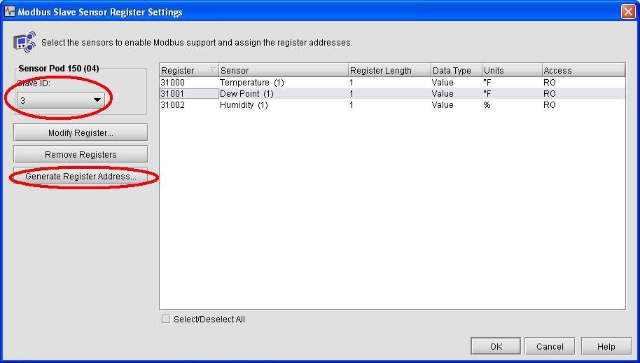
6 Figure 2 6
7 Figure 3 NetBotz Device Alarm Count The device alarm count register is common to all discovered devices. The device alarm count register will always remain and will display the maximum number of active alarms per device/sensor pod. Devices that have unmapped register values will return 0xDEAD as seen below. Modbus Description Value Description Active Alarm Count 0x Max Active Alarm Count Magic Values 0xDEAD Value refers to an empty or unmapped register NetBotz Device Status The device status register is common to all discovered devices. The device status register will always remain at with the register value changing. Below are the following register values for device status: 7
8 Description Modbus Value Description Device Status 0x xFFFD Device discovery phase is in progress 0xFFFE No Status is available for device 0xFFFF Ok state 0x0000 0x0001 0x0002 0x0003 0x0004 Informational state Device is in warning state Device is in error state Device is in critical state Device is in failure state NetBotz Device Alarm Codes In the Following table are the Alarm codes common to all devices. Each alarm will have two registers per alarm with the registers starting prior to For example: If there are 10 devices sensors in an alarm state each with one alarm, you would need to poll the 20 registers prior to to display the alarm code (the first register) and the sensor code for the device (the second register) it corresponds to. Description Modbus Value Description Each alarm spans 0x30998 (max 0xFFFE Device alarm two registers with alarms reported) *2 0xFFFF Exclude (test) alarm the first register representing the 0x0001 Device info alarm alarm code and 0x0002 Communication lost the second 0x0003 Threshold : too low representing the corresponding 0x0004 Threshold : too low too long sensor. 0x0005 Threshold : too high 0x0006 Threshold : too high too long 0x0007 Threshold : increase too fast 0x0008 Threshold : decrease too fast 0x0009 Threshold : state change 0x0010 DDF Download Failure 0x0011 Capture drive failure 0x0012 Remote link failed 0x0013 Log on error Alarms are read as a negative offset from the Device Status 0x0014 General Device Alarm (0x30998) up to Max alarms reported. Alarms are provided in order of severity. A single alarm occupies two registers. 0x???? Specific device alarms (see each device alarm table for the ModBus register value and register value description) 8
9 NetBotz Corresponding Device Sensor Codes In the following table, the corresponding sensor codes are paired with the above alarm codes. 0xFFFF 0xFFFE Sensor register # Value Description Sensor association unknown. Sensor association known but sensor not mapped to a register. Address of the register mapped to the alarming sensor Environmental Management System Device Alarm Codes (EMS) The following table contains Modbus alarm codes specific to the EMS. Value Description Value Description 0x031A Lost communication with the management interface 0x1A21 0x1902 Sensor disconnected 0x1A23 Maximum temperature 0x1903 threshold 0x1A25 High temperature threshold 0x1905 0x1A27 Low temperature threshold 0x1907 0x1A29 0x1909 0x190B 0x190D 0x190F 0x1911 0x1913 0x1915 Discrete input abnormal state with 'informational' severity Maximum analog input threshold High analog input threshold Low analog input threshold Minimum analog input threshold Minimum temperature threshold 0x1A2C Beacon disconnected Maximum humidity threshold 0x1A2D Beacon on High humidity threshold 0x1A31 Relay output abnormal state Low humidity threshold 0x1A33 Switched outlet abnormal state Minimum humidity threshold 0x1A35 Current limit exceeded Short-term increasing 0x1B02 Lost communication Short-term decreasing 0x1B04 Sensor disconnected 9
10 0x1917 0x1919 Value Description Value Description Long-term increasing Long-term decreasing 0x1B05 0x1B07 0x1A02 Lost communication 0x1B09 0x1A04 Sensor disconnected 0x1B0B Maximum temperature 0x1A05 threshold 0x1B0D 0x1A07 0x1A09 0x1A0B 0x1A0D 0x1A0F 0x1A11 0x1A13 0x1A15 0x1A17 0x1A19 0x1A1B Maximum temperature threshold High temperature threshold Low temperature threshold Minimum temperature threshold Maximum humidity threshold High temperature threshold 0x1B0F High humidity threshold Low temperature threshold 0x1B11 Low humidity threshold Minimum temperature threshold Maximum humidity threshold High humidity threshold Low humidity threshold Minimum humidity threshold Short-term increasing Short-term decreasing Long-term increasing 0x1B13 0x1B15 0x1B17 0x1B19 0x1B1B 0x1B1D 0x1B1F 0x1B21 Minimum humidity threshold Short-term increasing Short-term decreasing Long-term increasing Long-term decreasing Discrete input abnormal state with 'critical' severity Discrete input abnormal state with 'warning' severity Discrete input abnormal state with 'informational' severity Long-term decreasing 0x1B24 Beacon disconnected 10
11 0x1A1D 0x1A1F Value Description Value Description Discrete input abnormal state with 'critical' severity 0x1B25 Beacon on Discrete input abnormal state with 'warning' severity Environmental Monitoring Unit Device Alarm Codes (EMU) The following table contains Modbus alarm codes specific to the EMU. Value Description 0x031A Lost Communication 0x0329 Critical fault on integrated Environmental Monitor input 0x031B contact 0x031D Warning fault on integrated Environmental Monitor input 0x0343 contact 0x031F 0x0349 0x0323 Lost communication to the integrated Environmental Monitor input contact A high humidity threshold exists for integrated Environmental Monitor Sensor 0x0327 0x032D Value Description A minimum temperature threshold exists for integrated Environmental Monitor Sensor A low temperature threshold exists for integrated Environmental Monitor Sensor A high temperature threshold exists for integrated Environmental Monitor Sensor A maximum temperature threshold exists for integrated Environmental Monitor Sensor A minimum humidity threshold exists for integrated Environmental Monitor Sensor 0x032B A maximum humidity threshold exists for integrated Environmental Monitor Sensor 0x0321 A low humidity threshold exists for integrated Environmental Monitor Sensor 0x0347 Lost Communication 11
12 Network Air FM Device Alarm Codes The following table contains Modbus alarm codes specific to the Network Air FM. Value Description Value Description 0x1303 Module power on 0x13B9 VFD 1 fault tolerance exceeded 0x1305 Water detected 0x13BB VFD 2 fault tolerance exceeded 0x1307 Fire detected 0x13BD Cooling coil: No fluid flow 0x1309 Smoke detected 0x13BF Condenser: No fluid flow 0x130D Head pressure high 0x13C1 Lost communication with expansion module 1 0x130F Condensate pump failed 0x13C3 Lost communication with expansion module 2 0x1311 Air block interlock open 0x13C5 Lost communication with expansion module 3 0x1319 Environmental temperature high 0x13C7 VFD 1 maintenance required 0x131B Environmental temperature low 0x13C9 VFD 2 maintenance required 0x131D Environmental humidity high 0x13CB Coil fluid inlet temperature high 0x131F Environmental humidity low 0x13CD Coil fluid inlet temperature low 0x1325 Suction pressure high 0x13CF Hot water inlet temperature high 0x1327 Suction pressure low 0x13D1 Hot water inlet temperature low 0x132D Supply temperature high 0x13D3 Economizer isolator valve active 0x132F Supply temperature low 0x13D5 Coil fluid inlet temperature sensor failed 0x1335 Humidifier water conductivity high 0x13D7 Return sensor failed 0x1337 Humidifier excessive foam 0x13D9 Supply sensor failed 0x1339 Humidifier current high 0x13DB Module enabled 0x133B Humidifier without power 0x13DD Input #1 asserted 0x133D Humidifier internal memory error 0x13DF Input #2 asserted 0x133F Humidifier water level low 0x13E1 Input #3 asserted 0x1341 Humidifier water level reduction excessive 0x13E3 Input #4 asserted 0x1343 Humidifier drain malfunction 0x13E5 Input #5 asserted 12
13 Value Description Value Description Humidifier cylinder full when unit off 0x13E7 Input #6 asserted 0x1345 0x1347 Humidifier replace cylinder 0x13E9 Input #7 asserted 0x1349 Air flow low 0x13EB Input #8 asserted 0x134B Coil fluid valve actuator failed 0x13ED Input #9 asserted 0x134D Condenser valve actuator failed 0x13EF Input #10 asserted 0x134F Hot water valve actuator failed 0x13F1 Input #11 asserted 0x1351 VFD 1 acceleration overcurrent 0x13F3 Input #12 asserted 0x1353 VFD 2 acceleration overcurrent 0x13F5 Input #13 asserted 0x1355 VFD 1 deceleration overcurrent 0x13F7 Input #14 asserted 0x1357 VFD 2 deceleration overcurrent 0x13F9 Input #15 asserted 0x1359 VFD 1 steady operation overcurrent 0x13FB Input #16 asserted 0x135B 0x135D 0x135F VFD 2 steady operation overcurrent VFD 1 steady operation overvoltage VFD 2 steady operation overvoltage 0x13FD 0x13FF 0x1403 0x1361 VFD 1 DC undervoltage 0x1405 0x1363 VFD 2 DC undervoltage 0x1407 VFD 1 power supply open 0x1365 phase 0x1409 VFD 2 power supply open 0x1367 phase 0x140B Remote sensor at address 3 removed Remote sensor at address 4 removed Remote sensor at address 5 removed Remote sensor at address 6 removed Remote sensor at address 7 removed Remote sensor at address 8 removed Remote sensor at address 9 removed Remote sensor at address 10 removed 0x1369 VFD 1 output wiring error 0x140D 0x136B VFD 2 output wiring error 0x140F Remote sensor added 0x136D VFD 1 heat sink temperature high 0x1411 Primary sensors failed 0x136F VFD 2 heat sink temperature high 0x1413 Secondary Sensors failed 0x1371 VFD 1 motor 1 overload 0x1415 Secondary sensors active 13
14 Value Description Value Description 0x1373 VFD 2 motor 1 overload 0x1417 System is offline 0x1375 VFD 1 overload 0x1419 System failure 0x1377 VFD 2 overload 0x141B Backup system online 0x1379 VFD 1 acceleration overvoltage 0x141D System power off 0x137B VFD 2 acceleration overvoltage 0x141F System is load sharing 0x137D VFD 1 deceleration overvoltage 0x1421 Backup system unavailable 0x137F VFD 2 deceleration overvoltage 0x1423 System smoke detected 0x1381 VFD 1 external thermal sensor temperature high 0x1425 System fire detected 0x1383 VFD 2 external thermal sensor temperature high 0x1427 Group fatal smoke alarm 0x1385 VFD 1 braking resistor overheated 0x1429 Group fatal fire alarm 0x1387 VFD 2 braking resistor temperature high 0x142B System communication lost 0x1389 VFD 1 motor 2 overload 0x142D Group configuration invalid 0x138B VFD 2 motor 2 overload 0x142F Group configuration conflict 0x138D VFD 1 memory error 0x1431 Module firmware mismatch 0x138F VFD 2 memory error 0x1433 System firmware mismatch 0x1391 VFD 1 keypad transmission error 0x1435 Module download failure 0x1393 VFD 2 keypad transmission error 0x1437 VFD 1 mains failure 0x1395 VFD 1 CPU error 0x1439 VFD 2 mains failure 0x1397 VFD 2 CPU error 0x143B VFD 1 overvoltage 0x1399 VFD 1 option communication error 0x143D VFD 2 overvoltage 0x139B VFD 2 option communication error 0x143F VFD 1 inverter overload 0x139D VFD 1 option error 0x1441 VFD 2 inverter overload 0x139F VFD 2 option error 0x1443 VFD 1 motor failure 0x13A1 VFD 1 drive startup error 0x1445 VFD 2 motor failure 0x13A3 VFD 2 drive startup error 0x1447 VFD 1 power card fail 0x13A5 VFD 1 RS485 communication error 0x1449 VFD 2 power card fail 0x13A7 VFD 2 RS485 communication error 0x14AF Mains A failure 14
15 Value Description Value Description 0x13A9 Air filter clogged 0x14B1 Mains B failure 0x13AB Compressor 1 maintenance required 0x14B3 Humidifier RS-485 failure 0x13AD Compressor 2 maintenance required 0x14B5 Persistent low suction pressure 0x13AF Heater maintenance required 0x14FB The NMC firmware is older than the corresponding device firmware 0x13B1 0x13B3 0x13B5 Humidifier maintenance required Blower 1 maintenance required Blower 2 maintenance required 0x14FD 0x14FF 0x13B7 The NMC firmware is newer than the corresponding device firmware The ISX Central is still able to communicate with the NMC but the NMC cannot communicate with the device Humidifier fault tolerance exceeded In Row SC Device Alarm Codes The following table contains Modbus alarm codes specific to the In Row SC. Value Description Value Description 0x2302 An internal communication fault exists 0x2330 A fan power supply left fault exists 0x2304 An a-link isolation relay fault exists 0x2332 A fan power supply right fault exists 0x2308 An external communication fault exists 0x2334 An air filter run hours exists 0x2310 A cooling failure exists 0x2336 A condenser fan 1 fault exists 0x2312 A rack inlet high temperature exists 0x2338 A condenser fan 2 fault exists 0x2314 An air filter clogged fault exists 0x233A A condenser fan 3 fault exists 0x2316 A return air sensor fault exists 0x233C A supply air high temperature exists 0x2318 A condenser inlet air sensor fault exists 0x233E A return air high temperature exists 0x231A A supply air sensor fault exists 0x2340 A filter sensor fault exists 0x231C A condenser outlet air sensor fault exists 0x2344 A suction temperature sensor fault exists 15
16 0x231E 0x2320 0x2322 0x2324 0x2326 0x2328 Value Description Value Description A rack inlet temperature sensor fault exists A high discharge pressure alarm exists A low suction pressure alarm An evaporator fan 1 fault An evaporator fan 2 fault An evaporator fan 3 fault 0x2346 0x2348 0x234C 0x234E 0x2350 0x2352 A suction pressure sensor fault exists A discharge pressure sensor fault exists On standby an input contact fault A persistent high discharge pressure alarm A persistent low suction pressure alarm A startup low suction pressure alarm 0x232A A water detection fault 0x2354 A startup line pressure imbalance alarm 0x232C A condensate pump fault 0x2356 Lost group communication. 0x232E A condensate pan full fault In Row RP Device Alarm Codes The following table contains Modbus alarm codes specific to the In Row RP. 0x2C02 0x2C04 0x2C08 Value Description An internal communication fault An A-link isolation relay fault An external communication fault 0x2C4A 0x2C4C 0x2C4E 0x2C10 A cooling failure 0x2C50 A rack inlet high temperature 0x2C12 0x2C52 An air filter clogged fault 0x2C14 0x2C54 An upper return air sensor fault 0x2C16 0x2C5C Value Description A suction temperature sensor fault A suction pressure sensor fault A discharge pressure sensor fault On standby an input contact fault A persistent high discharge pressure alarm A persistent low suction pressure alarm An outside heat exchanger fault 16
17 0x2C1A 0x2C1C 0x2C1E 0x2C20 0x2C22 0x2C24 0x2C26 0x2C28 0x2C2A 0x2C2C 0x2C2E 0x2C30 Value Description Value Description A lower return air sensor fault An upper supply air sensor fault A middle supply air sensor fault A lower supply air sensor fault 0x2C60 0x2C62 0x2C64 0x2C66 A factory configuration not completed alarm A liquid refrigerant sensor fault An excessive compressor cycling alarm A no backup units available alarm A rack inlet temperature sensor fault 0x2C38 A condensate pump fault A condensor fluid actuator fault A high discharge pressure alarm A low suction pressure alarm An evaporator fan 1 fault 0x2C3A 0x2C3C 0x2C3E A condensate pan full fault An upper fan power supply fault A lower fan power supply fault An air filter run hours 0x2C40 An evaporator fan 2 fault 0x2C42 Lost group communication. An evaporator fan 3 fault An evaporator fan 4 fault An evaporator fan 5 fault 0x2C44 0x2C46 A supply air high temperature A return air high temperature 0x2C32 0x2C48 A filter sensor fault An evaporator fan 6 fault 0x2C34 0x2C36 A water detection fault Internal communication fault Humidifier communication fault 0x1F02 0x1F56 0xlink isolation relay fault Compressor run hours 0x1F04 0x1F58 External communication fault Heater 1 run hours 0x1F08 0x1F5A Heater 2 run hours 0x1F10 Cooling failure 0x1F5C Rack inlet 1 high temperature Heater 3 run hours 0x1F12 0x1F5E 0x1F14 Rack inlet 2 high temperature 0x1F60 Humidifier run hours 0x1F16 Rack inlet 3 high temperature 0x1F62 Fan 1 run hours 0x1F18 High humidity 0x1F64 Fan 2 run hours 17
18 Value Description Value Description 0x1F1A Low humidity 0x1F66 Fan 3 run hours 0x1F1C Air filter clogged fault 0x1F68 Air filter run hours 0x1F1E Return air sensor fault 0x1F6A Condensate pump run hours 0x1F20 Supply air upper sensor fault 0x1F6C Lost group communication. 0x1F22 Rack inlet temperature sensor 1 fault 0x1F6E Compressor drive communication fault 0x1F24 Rack inlet temperature sensor 2 fault 0x1F70 Supply air high temperature 0x1F26 Rack inlet temperature sensor 3 fault 0x1F72 Return air high temperature 0x1F28 Coil fluid valve actuator fault 0x1F74 Filter sensor fault 0x1F2A High discharge pressure alarm 0x1F78 Suction pressure sensor fault 0x1F2C Low suction pressure fault alarm 0x1F7A Discharge pressure sensor fault 0x1F2E High suction pressure fault alarm 0x1F7E On standby an input contact fault 0x1F30 Frequent Humidifier faults. 0x1F80 Humidity supply sensor fault 0x1F32 Fan 1 fault 0x1F82 Humidity return sensor fault 0x1F34 Fan 2 fault 0x1F84 Heater 1 fault 0x1F36 Fan 3 fault 0x1F86 Heater 2 fault 0x1F38 Water detection fault 0x1F88 Heater 3 fault 0x1F3A Condensate pump fault 0x1F8A Compressor high pressure alarm 0x1F3C Fluid flowmeter fault 0x1F8C Fan speed decreased to avoid water emission. 0x1F3E Humidifier water conductivity too high. 0x1F8E Fan speed decreased to avoid compressor high pressure. 0x1F40 Humidifier low water level alarm 0x1F90 Compressor speed decreased to avoid abnormal pressure. 0x1F42 Humidifier excessive output reduction alarm 0x1F92 Heater Interlock Shutdown 0x1F44 Humidifier drain fault 0x1F94 Invalid Supply Air Setpoint condition 0x1F46 Humidifier cylinder full when unit off alarm 0x1F96 Fluid calibration activated by user. 0x1F48 Replace humidifier cylinder alarm 0x1F98 Cooling unit idle. 0x1F4A Compressor drive fault 0x1F9A Oil return pump active. 18
19 0x1F4C 0x1F4E 0x1F50 0x1F52 0x1F54 Value Description Value Description Compressor drive warning Supply air lower sensor fault 0x1F9C Entering fluid high temperature Air flow decreased while 0x1F9E compressor off. Entering fluid temperature sensor fault 0x1FA0 Excessive compressor cycling. Leaving fluid temperature sensor fault 0x1FA2 Persistent high head pressure. Power supply feed A fault In Row RC Device Alarm Codes The following table contains Modbus alarm codes specific to the In Row RC. Value Description Value Description 0x1D02 Internal communication fault exists 0x1D2A Condensate pump fault exists 0x1D04 A-link isolation relay fault exists 0x1D2C Fluid flowmeter fault exists 0x1D06 Cooling failure exists 0x1D2E Entering fluid high temperature exists 0x1D08 Rack inlet high temperature exists 0x1D30 Entering fluid temperature sensor fault exists 0x1D0A Air filter clogged fault exists 0x1D32 Leaving fluid temperature sensor fault exists 0x1D0C Lower return air sensor fault exists 0x1D34 Condensate pan full fault exists 0x1D0E Upper return air sensor fault exists 0x1D36 Power source A failure exists 0x1D10 Lower supply air sensor fault exists 0x1D38 Power source B failure exists 0x1D12 Upper supply air sensor fault exists 0x1D3A Fan power supply left fault exists Rack inlet temperature sensor fault Fan power supply right fault 0x1D14 exists 0x1D3C exists 0x1D16 Coil fluid valve actuator fault exists 0x1D3E Air filter run hours exists 0x1D18 Fan 1 fault exists 0x1D42 On standby input contact fault exists 0x1D1A Fan 2 fault exists 0x1D44 Supply air high temperature exists 19
20 Value Description Value Description Return air high temperature 0x1D1C Fan 3 fault exists 0x1D46 exists 0x1D1E Fan 4 fault exists 0x1D48 Group communication lost 0x1D20 Fan 5 fault exists 0x1D4A Filter sensor fault exists 0x1D22 Fan 6 fault exists 0x1D4E Fluid calibration activated by user. 0x1D24 Fan 7 fault exists 0x1D52 External communication fault exists 0x1D26 Fan 8 fault exists 0x1D28 Water detection fault exists Air Removal Unit (ARU) Device Alarm Codes The following table contains Modbus alarm codes specific to the ARU. 0x1201 0x1202 0x1203 Value Description Internal communication fault 0x1206 Value Description The overall operation of the fan has exceeded the runhour threshold Exhaust temperature cannot be maintained (critical). 0x1207 No redundant AC input present. Exhaust temperature violates the override setpoint. 0x1208 0x1204 Fan failure 0x1209 0x1205 Fan speed (rpm) fault detected. 0x120A Controller firmware update timed out. Firmware upgrade of ARU controller has ended in a failure. The data version of the ARU controller is incompatible with the data version of the Network Management Interface. Stultz Chiller Device Alarm Codes The following table contains Modbus alarm codes specific to Stultz Chillers. Value Description 0x3002 Lost Communication 0x3076 Value Description Sensor 14 is returning invalid values. 20
21 Value Description Value Description Sensor 15 is returning invalid values. Sensor 16 is returning invalid values. Sensor 17 is returning invalid values. Sensor 18 is returning invalid values. Sensor 19 is returning invalid values. 0x3004 No description available. 0x3078 0x3006 No description available. 0x307A 0x3008 No description available. 0x307C 0x300A A common alarm 0x307E 0x300C Unit requires maintenance. 0x3080 0x300E 0x3010 0x3012 0x3014 0x3016 A/C Fan 1 has stopped spinning. A/C Fan 2 has stopped spinning. A/C Fan 3 has stopped spinning. A high pressure alarm exists in circuit 1. A high pressure alarm exists in circuit 2. 0x3082 0x3084 0x3086 0x3088 0x308A 0x3018 Water has been detected. 0x308C 0x301A A phase failure has occurred. 0x308E Fire/Smoke has been 0x301C detected. 0x3090 A return air high temperature 0x301E 0x3092 A return air high humidity 0x3020 0x3094 A supply air high temperature 0x3022 0x3096 A supply air high humidity 0x3024 0x3098 A water high temperature 0x3026 0x309A A return air low temperature 0x3028 0x309C A return air low humidity 0x302A 0x309E Sensor 20 is returning invalid values. Sensor 21 is returning invalid values. Compressor 1 overload protection is active. Compressor 2 overload protection is active. A low pressure alarm exists in circuit 1. A low pressure alarm exists in circuit 2. Electrical re-heat stage 1 is overheated. Electrical re-heat stage 2 is overheated. Electrical re-heat stage 3 is overheated. Electrical re-heat stage 4 is overheated. An alarm condition exists in Dry Cooler 1. An alarm condition exists in Dry Cooler 2. An alarm condition exists in Dry Cooler 3. An alarm condition exists in Dry Cooler 4. An alarm condition exists in Pump 1. 21
22 0x302C 0x302E 0x3030 0x3032 0x3034 0x3036 0x3038 0x303A 0x303C 0x303E 0x3040 0x3042 0x3044 0x3046 0x3048 0x304A 0x304C 0x304E 0x3050 0x3052 Value Description Value Description A supply air low temperature A supply air low humidity A water low temperature Sensor 1 value deviates beyond acceptable limit. Sensor 2 value deviates beyond acceptable limit. Sensor 3 value deviates beyond acceptable limit. Sensor 4 value deviates beyond acceptable limit. Sensor 5 value deviates beyond acceptable limit. Sensor 6 value deviates beyond acceptable limit. Sensor 7 value deviates beyond acceptable limit. Sensor 8 value deviates beyond acceptable limit. Sensor 9 value deviates beyond acceptable limit. 0x30A0 0x30A2 0x30A4 0x30A6 0x30A8 0x30AA 0x30AC 0x30AE 0x30B0 0x30B2 0x30B4 0x30B6 An alarm condition exists in Pump 2. An alarm condition exists in Pump 3. An alarm condition exists in Pump 4. An alarm condition exists in Humidifier 1. An alarm condition exists in Humidifier 2. An alarm condition exists in Humidifier 3. A 5uS alarm exists in Humidifier 1. A 5uS alarm exists in Humidifier 2. A 5uS alarm exists in Humidifier 3. A 20uS alarm exists in Humidifier 1. A 20uS alarm exists in Humidifier 2. A 20uS alarm exists in Humidifier 3. Sensor 10 value deviates beyond acceptable limit. 0x30B8 An alarm exists in Fan 1. Sensor 11 value deviates beyond acceptable limit. 0x30BA An alarm exists in Fan 2. Sensor 12 value deviates beyond acceptable limit. 0x30BC An alarm exists in Fan 3. Sensor 13 value deviates beyond acceptable limit. 0x30BE Fan 1 filter is clogged. Sensor 14 value deviates beyond acceptable limit. 0x30C0 Fan 2 filter is clogged. Sensor 15 value deviates beyond acceptable limit. 0x30C2 Fan 3 filter is clogged. Sensor 16 value deviates beyond acceptable limit. 0x30C4 External Alarm 1 is active. Sensor 17 value deviates beyond acceptable limit. 0x30C6 External Alarm 2 is active. 22
23 0x3054 0x3056 0x3058 0x305A 0x305C 0x305E 0x3060 0x3062 0x3064 0x3066 0x3068 0x306A 0x306C 0x306E 0x3070 0x3072 0x3074 Value Description Value Description Sensor 18 value deviates beyond acceptable limit. 0x30C8 External Alarm 3 is active. Sensor 19 value deviates beyond acceptable limit. 0x30CA External Alarm 4 is active. Sensor 20 value deviates beyond acceptable limit. 0x30CC External Alarm 5 is active. Sensor 21 value deviates beyond acceptable limit. 0x30CE External Alarm 6 is active. Sensor 1 is returning invalid values. 0x30D0 External Alarm 7 is active. Sensor 2 is returning invalid values. 0x30D2 External Alarm 8 is active. Sensor 3 is returning invalid values. 0x30D4 External Alarm 9 is active. Sensor 4 is returning invalid values. 0x30D6 External Alarm 10 is active. Sensor 5 is returning invalid values. 0x30D8 A Hot Gas Re-Heat alarm Sensor 6 is returning invalid values. Sensor 7 is returning invalid values. Sensor 8 is returning invalid values. Sensor 9 is returning invalid values. Sensor 10 is returning invalid values. Sensor 11 is returning invalid values. 0x30DA 0x30DC 0x30DE 0x30E0 0x30E2 0x30E4 A circuit 1 electronic expansion valve pressure sensor error condition A circuit 1 electronic expansion valve temperature sensor error condition A circuit 1 electronic expansion valve stepper motor error condition A circuit 2 electronic expansion valve pressure sensor error condition A circuit 2 electronic expansion valve temperature sensor error condition A circuit 2 electronic expansion valve stepper motor error condition Sensor 12 is returning invalid values. 0x30E6 A freeze alarm is active. Sensor 13 is returning invalid values. 0x30E8 A dehumidifier alarm is active. 23
24 Power Generation Automatic Transfer Switch (ATS) Device Alarm Codes The following table contains Modbus alarm codes specific to the ATS. Value Description Value Description 0x1714 0x1716 0x1724 0x1726 0x1760 0x17C4 0x17C6 0x17D1 0x17D7 0x1704 The output voltage on phase has fallen below the low voltage threshold. The output voltage on phase has risen above the high voltage threshold. The output current on phase has fallen below the low current threshold. The output current on phase has risen above the high current threshold. 0x17D3 0x17C7 0x17C2 0x17C1 The generator failed to stop. After de-assertion of the Engine Start signal the quality of Source 2 continued to be seen as good. InfraStruXure ATS is not in automatic mode. The device's Emergency Power Off (EPO) circuit is tripped. The device's Emergency Power Off (EPO) circuit has been switched back to the test position. The ATS output frequency is outside the range. 0x174E The initiated test has failed. There is an internal communication error in the device. A data incompatibility exists within the device. This is typically the result of mismatches between firmware revisions of the transfer switch controller and the Network Management interface. The InfraStruXure ATS cannot communicate with the generator. The InfraStruXure ATS could not read these registers from the generator The InfraStruXure ATS has transferred to neutral position. In this position neither Source 1 nor Source 2 is selected and the ATS will have no output voltage. The ATS is now running in mode. 0x1780 0x1781 0x1782 0x1783 0x17D4 User input contact on the device is in an abnormal state. User input contact on the device is in an abnormal state. User input contact on the device is in an abnormal state. User input contact on the device is in an abnormal state. The state of the generator's Remote Start input and the ATS's Engine Start output do not match. This indicates something wrong in the Engine Start wiring which must be corrected. This condition may prevent the generator from being started when needed. 24
25 Value Description Value Description 0x17CC An internal InfraStruXure ATS fault has been detected. The ATS may have forced itself to not-in-auto mode (abnormal condition). 0x17C5 The InfraStruXure ATS exterior panel door is open. 0x17D2 The generator failed to start. After assertion of the Engine Start signal the quality of Source 2 was poor 0x17CB The InfraStruXure ATS' DC backup has been lost. The ATS will lose power on Source 1 failure causing the Engine Start signal to be asserted. The ATS will then restart from Source 2. Rack Automatic Transfer Switch (ATS) Device Alarm Codes The following table contains Modbus alarm codes specific to the ATS. 0x0C02 Value Description The ability to switch between input sources was lost 0x0C12 0x0C06 Lost Communication 0x0C14 An Overload threshold 0x0C07 exists 0x0C16 A fault exists at the power 0x0C09 supply 0x0C18 A Low Load threshold 0x0C0B exists 0x0C1A 0x0C0D 0x0C0F Value Description Source is unavailable or a status problem exists The RMS Voltage is above the allowed limit at Source (x) The RMS Voltage is below the allowed limit at Source (x) The frequency is above the allowed limit at Source (x) The frequency is below the allowed limit at Source (x) A near overload threshold exists 0x0C20 A fault exists at the hardware An overload threshold exists Metered and Switched Rack Power Distribution Unit (RPDU) Device Alarm Codes The following table contains Modbus alarm codes specific to the RPDU 0x0F01 0x0F03 Value Description A low load threshold exists at Bank (x) 0x0F14 Value Description An overload threshold exists at Phase (x) A near overload threshold exists at Bank (x) 0x0F16 A power supply 1 fault exists 25
26 0x0F05 Value Description Value Description An overload threshold exists at Bank (x) 0x0F18 A power supply 2 fault exists A low load threshold exists at Outlet bank (x) 0x0F08 Lost communication 0x0F1F 0x0F10 0x0F12 A low load threshold exists at Phase (x) A near overload threshold exists at Phase (x) 0x0F21 0x0F23 A near overload threshold exists at Outlet bank (x) An overload threshold exists at Outlet bank (x) InfraStruXure Remote Power Distribution Unit Device Alarm Codes The following table contains Modbus alarm codes specific to the Remote InfraStruXure PDU. 0x2A80 0x2A81 0x2A82 0x2A83 Value Description User Contact 1 is not in the normal state. User Contact 2 is not in the normal state. User Contact 3 is not in the normal state. User Contact 4 is not in the normal state. 0x2A84 0x2A85 0x2A86 0x2A87 Value Description User Contact 1 is not in the normal state. User Contact 2 is not in the normal state. User Contact 3 is not in the normal state. User Contact 4 is not in the normal state. InfraStruXure Power Distribution Unit Device Alarm Codes The following table contains Modbus alarm codes specific to the InfraStruXure PDU. 0x1610 Value Description The input voltage on phase (x) has fallen below the input voltage low threshold 0x2406 Value Description Communication lost with the metering board for modules. 0x1612 The input voltage on phase (x) has risen above the input voltage high threshold 0x2410 Distribution module breaker current is below the minimum threshold 0x1614 The output voltage on phase (x) has fallen below the output voltage low threshold 0x2412 Distribution module breaker current is below the low threshold 26
27 Value Description Value Description 0x1616 The output voltage on phase (x) has risen above the output voltage high threshold 0x2414 Distribution module breaker current is above the high threshold 0x1618 0x161A The bypass voltage on phase (x) has fallen below the bypass voltage low threshold The bypass voltage on phase (x) has risen above the bypass voltage high threshold 0x2416 0x2418 Distribution module breaker current is above the maximum threshold Distribution module breaker is open. 0x1624 The output current in phase (x) has fallen below the output current low threshold 0x2420 Distribution subfeed phase (x)current is below the minimum threshold 0x1626 The output current in phase (x) has risen above the output current high threshold 0x2422 Distribution subfeed phase (x) current is below the low threshold 0x1662 The neutral current has risen above the neutral current high threshold 0x2424 Distribution subfeed phase (x) current is above the high threshold 0x1640 0x1644 0x1648 0x164C 0x1650 0x1660 The main input breaker has been opened. The output breaker (Q2) has been opened. The bypass feed breaker has been opened. The cross tie breaker has been opened. The UPS input fuse on phase (x) has failed. The PDU output frequency is outside the range 0x2426 0x2428 0x1630 0x1632 0x1634 0x1636 Distribution subfeed phase (x) current is above the maximum threshold Distribution subfeed breaker is open. The current in branch has fallen below the branch current low threshold The current in branch has risen above the branch current high threshold The current in branch has fallen below the branch current minimum threshold The current in branch has risen above the branch current maximum threshold 27
28 0x1680 0x1681 0x1682 0x1683 0x1690 0x1691 0x1692 0x1693 0x16C1 0x16C3 0x16D1 0x16C4 0x16CC 0x16C6 0x16C8 Value Description Value Description User Contact 1 is not in the normal state. User Contact 2 is not in the normal state. User Contact 3 is not in the normal state. User Contact 4 is not in the normal state. Output Relay 1 is not in the normal state. Output Relay 2 is not in the normal state. Output Relay 3 is not in the normal state. Output Relay 4 is not in the normal state. The PDU is in maintenance bypass. PDU Emergency Power Off Mode Set to Test PDU Emergency Power Off Mode tripped PDU Internal Communication 0x2948 0x2A80 0x2A81 0x2A82 0x2A83 0x2A84 0x2A85 0x2A86 0x2A87 0x29C1 0x29C6 The bypass feed switch has been opened. A critical fault exists for integrated environmental input contact 1 A critical fault exists for integrated environmental input contact 2 A critical fault exists for integrated environmental input contact 3 A critical fault exists for integrated environmental input contact 4 A warning fault exists for integrated environmental input contact 1. A warning fault exists for integrated environmental input contact 2. A warning fault exists for integrated environmental input contact 3. A warning fault exists for integrated environmental input contact 4. The system is in maintenance bypass. Input Isolation Transformer Over Temperature Failure 0x29C8 Transformer Cooling Fan Failure The data version of the PDU controller is incompatible with the data version of the Network Management Interface. 0x29CA System Mode Alarm PDU Input Isolation Transformer Over Temperature 0x16CA PDU System Mode Alarm PDU Cooling Fan Failure 28
29 Silcon UPS Device Alarm Codes The following table contains Modbus alarm codes specific to the Silcon UPS. Value Description Value Description 0x0102 Lost communication. 0x3A1F A weak battery 0x0103 0x0107 0x0109 0x010F The load exceeds 100% of rated capacity. The battery power is too low to support the load; if power fails the UPS will be shut down immediately. 0x3A23 0x3A25 The system is locked in operational mode. A RAM1 memory write fault On battery power in response to an input power problem. 0x3A27 A memory write fault The battery power is too low to continue to support the load; the UPS will shut down if input power does not return to normal soon. 0x3A29 0x0114 The output power is turned off. 0x3A2B In bypass in response to an 0x011B internal hardware fault. 0x3A2D In bypass in response to the bypass switch at the UPS 0x011D typically for maintenance. 0x3A2F 0x0125 0x012C A graceful shutdown process is being used to shut down the load equipment before the UPS turns off. The internal battery temperature exceeds the critical threshold. 0x3A31 0x3A33 Lost communication with the VQ bypass. Lost communication with the VQ output. Lost communication with the DMU. Lost communication with the controller. Lost communication with the parallel interface (IF). An external shutdown was accepted. 0x0148 Lost communication while the UPS was on battery. 0x3A35 0x0207 A battery fault 0x3A37 An input voltage or frequency problem prevents switching to 0x020F bypass mode. 0x3A39 A direct current (DC) capacitor charge fault Lost communication with the VQ Mains. A bypass synchronization fault 29
30 0x0217 0x022B 0x022D 0x022F 0x0231 0x3A01 Value Description Value Description In bypass in response to an overload. 0x3A3B A charge fault The output voltage is outside its defined limits. 0x3A3D The SII auxiliary input is activated. A phase synchronization fault 0x3A41 A blown inverter fuse The battery is not installed properly. 0x3A43 A blown rectifier fuse The battery voltage exceeds the nominal battery voltage rating. 0x3A45 An auxiliary 1 fault The peak current limiter is active. 0x3A5B A high temperature charger magnetic fault 0x3A03 A bypass power supply fault 0x3A5F A battery monitor warning 0x3A05 The delta current limiter is active. 0x3A61 A battery monitor alarm 0x3A07 A fan fault 0x3A69 A TSM 1/2/3 temperature shutdown 0x3A09 A high direct current (DC) warning 0x3A6B 0x3A0B An inverter voltage fault 0x3A6D 0x3A0D 0x3A0F 0x3A11 0x3A1B 0x3A1D A charger 0/30 temperature warning A charger 0/30 temperature shutdown A parallel synchronization fault 0x3A6F A high output voltage A second power supply fault An internal power supply fault A static bypass switch high temperature The battery temperature exceeds the critical threshold. 0x3A71 0x3A75 0x3A79 An SSW temperature over 90 fault A low current fault exists for the AC capacitors. The advanced battery management is not installed. Symmetra Three Phase UPS Device Alarm Codes The following table contains Modbus alarm codes specific to the Symmetra Three Phase UPS. Value Description Value Description 30
31 Value Description Value Description 0x0102 Lost Communication. 0x0223 0x0103 The load exceeds 100% of rated capacity. 0x0225 No power modules detected as installed. An input voltage or frequency problem occurred while on bypass turning off the UPS. 0x0106 0x0107 0x0109 0x010F The UPS failed its diagnostic self-test due to either an overload or poor battery health. The battery power is too low to support the load; if power fails the UPS will be shut down immediately. On battery power in response to an input power problem. The battery power is too low to continue to support the load; the UPS will shut down if input power does not return to normal soon. 0x0227 0x0229 0x022B 0x022D 0x0114 The output power is turned off. 0x022F Turned off for a defined period of time in response to a software command or off while waiting for input power to 0x0115 return to normal. 0x0231 0x0119 0x011C 0x0125 A runtime alarm threshold An extended run frame fault The output voltage is not within its defined limits. A phase synchronization fault No batteries detected as installed. The battery voltage exceeds the Nominal Battery Voltage rating. At least one faulty battery 0x0235 A site wiring fault In bypass in response to the UPS front-panel or a userinitiated software command typically for maintenance. 0x0237 The backfeed relay is open. A graceful shutdown process is being used to shut down the load equipment before the UPS turns off. 0x2601 0x012A A battery charger fault 0x2603 The internal battery 0x012C temperature exceeds the 0x2605 A maintenance bypass fault A high isolation transformer temperature The external DC disconnect switch is open. 31
32 Value Description Value Description critical threshold. 0x0148 Lost communication while the UPS was on battery. 0x2607 0x0201 A power module fault 0x2609 A main intelligence module 0x0203 fault 0x260B A redundant intelligence 0x0205 module fault 0x260D 0x0207 A battery fault 0x260F A load (kva) alarm threshold 0x0209 0x2611 0x020B 0x020D 0x020F 0x0211 0x0213 0x0215 0x0217 Lost power module redundancy. A redundancy alarm threshold An input voltage or frequency problem prevents switching to bypass mode. The bypass relay is stuck in its bypass position. The bypass relay is stuck in its online position. In bypass in response to an internal hardware fault. In bypass in response to an overload. 0x2613 0x2615 0x2617 0x2619 0x261B 0x261D 0x261F 0x0219 In bypass for maintenance. 0x2621 The input circuit breaker is 0x021B open. 0x2623 0x021D A system level fan fault 0x0221 The redundant intelligence 0x021F module is in control. A system power supply card fault A battery monitor card fault The battery monitor card was removed. An XR communication card fault The external run frame (XR) communication card was removed. An external switch gear communication card fault The external switch gear communication card was removed. The internal DC disconnect switch is open. A static bypass switch module fault The system ID card was removed. A system identification card fault In bypass in response to switchgear or UPS static switch. The static bypass switch module was removed. A system start-up configuration fault The battery charger is shutdown externally. An internal bus communication fault 32
33 Symmetra Single Phase UPS Device Alarm Codes The following table contains Modbus alarm codes to the Symmetra Single Phase UPS. Value Description Value Description 0x0102 Lost Communication. 0x0211 The load exceeds 100% of 0x0103 rated capacity. 0x0213 0x0107 0x0109 The battery power is too low to support the load; if power fails the UPS will be shut down immediately. On battery power in response to an input power problem. 0x0215 0x0217 The bypass relay is stuck in its bypass position. The bypass relay is stuck in its online position. In bypass in response to an internal hardware fault. In bypass in response to an overload. 0x010F The battery power is too low to continue to support the load; the UPS will shut down if input power does not return to normal soon. 0x0219 In bypass for maintenance. 0x0114 The output power is turned off. 0x021B The input circuit breaker is open. 0x0115 Turned off for a defined period of time in response to a software command or off while waiting for input power to return to normal. 0x021D A system level fan fault 0x0119 0x011C 0x0125 At least one faulty battery In bypass in response to the UPS front-panel or a userinitiated software command typically for maintenance. A graceful shutdown process is being used to shut down the load equipment before the UPS turns off. 0x021F 0x0221 0x0223 0x012A A battery charger fault 0x0225 The internal battery temperature exceeds the 0x012C critical threshold. 0x0227 The redundant intelligence module is in control. An IIC bus communication fault No power modules detected as installed. An input voltage or frequency problem occurred while on bypass turning off the UPS. A runtime alarm threshold 33
APC APPLICATION NOTE #160
 #160 NetBotz Building Management System (BMS) Integration By Jon Runk, Chuck Rafuse Abstract The Modbus protocol is a standard in the industry and is supported by almost all of the BMS vendors. integrates
Symmetra MW Modbus Data Points
 Symmetra MW Modbus Data Points Version 0.11.19.05 rev 1 General Information: There are two devices that constitute the Symmetra MW system: the UPS and the EBS. There is a separate point mapping for each
FieldServer Driver - Serial FS McQuay Microtech Open Protocol
 Description FieldServer Driver - Serial FS-8700-80 McQuay Microtech Open Protocol This is an active client protocol. The driver is capable of acting as a master or slave. As a master, the Fieldserver polls
F Technical Bulletin SC 370 SMART Modbus Interface
 F7904502 Document Revision History Document Versiosion Modbus Map Ver- Date Author Notes 1 10 9/26/17 JGG Document Created Flash Technology, 332 Nichol Mill Lane, Franklin, TN 37067 www.flashtechnology.com
APC BC300 Series 40kW 208/450/480V User Guide
 APC BC300 Series 40kW 208/450/480V User Guide Copyright 2002 APC Denmark ApS This manual is subject to change without notice and does not represent a commitment on the part of the vendor Thank You Thank
RS485 MODBUS Module 8AI
 Version 1.4 15/04/2013 Manufactured for Thank you for choosing our product. This manual will help you with proper support and proper operation of the device. The information contained in this manual have
Sales and Engineering Data Sheet ED
 Sales and Engineering Data Sheet ED 15121-7 Group: Controls Part Number: ED 15121 Date: July 2017 MicroTech III Chiller Unit Controller Protocol Information Modbus Networks ANSI/ASHRAE 135-2004, BACnet
Modbus TCP/IP Option Instruction Manual
 W A L C H E M An Iwaki America Company WebMaster Modbus TCP/IP Option Web Master WIND Modbus TCP/IP Option Instruction Manual s825v008 and higher Five Boynton Road Hopping Brook Park Holliston, MA 01746
A36D/TPSD Modbus TCP SCADA INTERFACE INSTRUCTIONS
 SCADA INTERFACE INSTRUCTIONS - OPTION 21Q - FOR A36D/TPSD SYSTEMS with 500 and 550 option. A36D/TPSD Modbus TCP SCADA INTERFACE OPTION 21Q INSTRUCTIONS This manual is valid for A36D/TPSD Chargers equipped
Sales and Engineering Data Sheet ED
 Sales and Engineering Data Sheet ED 15121-6 Group: Controls Part Number: ED 15121 Date: March 2017 MicroTech III Chiller Unit Controller Protocol Information Modbus Networks ANSI/ASHAE 135-2004, BACnet
MODBUS MESSAGING to the S5 BATTERY VALIDATION SYSTEM
 BTECH, Inc. 10 Astro Place Rockaway, NJ 07866 MODBUS MESSAGING to the S5 BATTERY VALIDATION SYSTEM Users Guide Rev 1.6 09OCT15 1.0 Description This feature of the S5 allows a plant computer (DCS) to monitor
P2267 NETWORK INTERFACE
 P2267 NETWORK INTERFACE USER MANUAL FOR OPERATING SYSTEMS: 22031-03 23636-01 October 2009 Associated Controls (Australia) Pty. Limited 2-4 Norfolk Road Greenacre, NSW, 2190. PH +61 2 9642 4922, FAX +61
NGC-40 Bridge. Modbus Overview. Raychem-AR-H58862-NGC40BridgeModbusOV-EN-1805 nvent.com 1
 NGC-40 Bridge Overview Raychem-AR-H58862-NGC40BridgeOV-EN-1805 nvent.com 1 Table of Contents 1. NGC-40 Overview... 9 1.1 Example NGC-40 System... 10 2. Legal stuff... 11 3. Protocols... 12 3.1 Data es...
Installation and User Guide
 Installation and User Guide User CTS 2 602 manual by Nilan VPM 360 Modbus Version: 2.00 08-05-2014 Software-version: 2.20 The following information describes how to connect to Nilan CTS 602 controls by
USER MANUAL FOR OPERATING SYSTEM
 P2262 ALARM PANEL USER MANUAL FOR OPERATING SYSTEM 21765-07 September 1999 Associated Controls (Aust) PTY. LTD. 29 Smith Street, Hillsdale, NSW, 2036. PH (02) 9311 3255, FAX (02) 9311 3779 Page 1 of 177
EXD-HP1/2 Stand-alone Superheat/Economizer Controller
 Technical Bulletin EXD-HP1/2 are stand-alone universal superheat and or economizer controllers for heat pumps, heating units, air conditioning and precision cooling such as telecom and shelter applications.
EOS INTERFACE GUIDE AND POINTS LIST For EOS BTCII Firmware Version J1239D-570 and newer
 Installation and interface must be performed by a qualified controls technician. IMPORTANT: THIS MANUAL CONTAINS INFORMATION REQUIRED FOR INSTALLATION, INTERFACE AND CONFIGURATION OF THIS EQUIPMENT. READ
VTI MODEL itc5000 HEAT TRACING CONTROL SYSTEM OPERATIONS MANUAL
 VTI MODEL itc5000 HEAT TRACING CONTROL SYSTEM OPERATIONS MANUAL 1 Operations Manual for the VTI Model itc5000 Heat Tracing Control System Description The VTI Model itc5000 Heat Tracing Control System consists
Database for CTS6000 MODBUS
 Database for CTS6000 MODBUS Valid for: LONcard SW1.7.4B, Variable List V2.02 Version 1.08-4, 01-05-2016 Contents Contents... 2 1. Installation... 3 1.1. Installation and operating instructions... 3 2.
Adaptive CyCLO Technical and HMI User Guide. CyCLO User Guide. Version th December 2017 REV
 CyCLO User Guide Version 2.00 19 th December 2017 REV 2.00 1 Contents 1. Hardware... 3 1.1. Introduction... 3 1.2. Electrical Specification... 3 1.3. Board Overview... 4 1.4. Electrical Installation...
Q-SMART MODBUS KIT. Modbus Protocol & Parameters. Cod EN rev.a ed.08/2018. Q-SMART Software Version AE17
 Q-SMART MODBUS KIT Modbus Protocol & Parameters Cod.001085120EN rev.a ed.08/2018 Q-SMART Software Version AE17 Index 1 Modbus Protocol on Q-SMART... 4 1.1 Broadcasting... 4 1.2 Data Protection... 4 1.3
A36D/TPSD Modbus RTU (Serial) SCADA INTERFACE INSTRUCTIONS
 SCADA INTERFACE INSTRUCTIONS") SCADA INTERFACE INSTRUCTIONS - OPTION 21S - FOR A36D/TPSD SYSTEMS with option 500 and 550. A36D/TPSD Modbus RTU (Serial) SCADA INTERFACE OPTION 21S INSTRUCTIONS This manual is valid for A36D/TPSD Chargers
SCADA INTERFACE INSTRUCTIONS - OPTION 21S - FOR A36D/TPSD SYSTEMS with option 500 and 550. A36D/TPSD Modbus RTU (Serial) SCADA INTERFACE OPTION 21S INSTRUCTIONS This manual is valid for A36D/TPSD Chargers
SM3000 Videographic Recorder. User Guide. Modbus (RTU) Communications Option
 Communications Option") SM3000 Videographic Recorder User Guide (RTU) Communications Option ABB The Company We are an established world force in the design and manufacture of instrumentation for industrial process control, flow
SM3000 Videographic Recorder User Guide (RTU) Communications Option ABB The Company We are an established world force in the design and manufacture of instrumentation for industrial process control, flow
FlameGard 5 MSIR HART
 FlameGard 5 MSIR HART Multi-Spectral Infrared Flame Detector HART Communication with the FlameGard 5 Multi-spectral Infrared Detector The information and technical data disclosed in this document may be
Setup Instructions. This manual is only valid for A36D/TPSD Chargers. equipped with a 341S control card with P341S0012 or P341S0013 software
 La Marche Manufacturing Company www.lamarchemfg.com DNP 3.0 Serial (RS232/RS485) and Ethernet (TCP/IP) SCADA Interface for A36D & TPSD Chargers with S2A-341S and S2A-383S communication cards. Option 21P,
FL500 Modbus Communication Operating Manual. Order No.: /00. MSAsafety.com
 FL500 Modbus Communication Operating Manual Order No.: 10193214/00 MSAsafety.com 1000 Cranberry Woods Drive Cranberry Township, PA 16066 A Phone 1-800-MSA-2222 Fax 1-800-967-0398 For your local MSA contacts
Series Digital Controller Instruction Sheet
 216/3/11 Series Digital Controller Instruction Sheet Thank you very much for purchasing DELTA DTC Series Temperature Controller. Please read this instruction sheet before using your DTC series to ensure
Operation Manual Fighter ProVision Software. Version: 0.0 Revision: 1
 Operation Manual Fighter ProVision Software Version: 0.0 Revision: 1 TABLE OF CONTENTS 1. Introduction 5 2. Software Installation 5 3. PC Users 6 3.1 Introduction 6 3.2 Default Code 6 3.3 Edit PC User
DTSX200 Communications(Modbus) Guide
 Guide") User s Manual DTSX200 Communications(Modbus) Guide 4th Edition Blank Page < Introduction > i Introduction About this Manual Thank you for purchasing the DTSX200 Distributed Temperature Sensor. This document
User s Manual DTSX200 Communications(Modbus) Guide 4th Edition Blank Page < Introduction > i Introduction About this Manual Thank you for purchasing the DTSX200 Distributed Temperature Sensor. This document
M2500 Engine Controller Installation Manual
 M2500 Engine Controller Installation Manual Revision: 23-04-2012 Page 1 Contents 1 Preface... 4 2 Installation... 5 3 Terminal Connections... 6 4 Inputs... 7 4.1 Power Supply... 7 4.2 Mode/ Control Inputs...
3.4 SPINDLE AMPLIFIER MODULE
 3. TROUBLESHOOTING AND 3. ACTION TO BE TAKEN TROUBLESHOOTING B 65165E/01 3.4 SPINDLE AMPLIFIER MODULE If an alarm occurs in the spindle amplifier module, the ALM LED lights red in the STATUS display, and
Metasys Integrator Airflow Application
 Metasys Connectivity Technical Manual 69. Metasys Integrator Section Application Note Issue Date 0998 APPLICATION NOTE Metasys Integrator Airflow Application lntroduction Page Application Details * Component
APPENDIX Detailed Requirements for ECHONET Device objects
 APPENDIX Detailed Requirements for ECHONET Device objects APPENDIX Detailed Requirements for ECHONET Device objects i 2000 (2013) ALL RIGHTS RESERVED APPENDIX Detailed Requirements for ECHONET Device objects
Galaxy Pulsar Plus Controller Family Troubleshooting Table with SMNP Traps
 Critical Power Product Manual Galaxy Pulsar Plus Controller Family Troubleshooting Table with SMNP s This document supplements CC848815341 Galaxy Pulsar Plus Controller Family Product Manual r07. Service
ibox Modbus Server Gateway for the integration of Notifier ID3000 / ID3002 / ID60 / ID50 fire panels in Modbus enabled monitoring and control systems
 Honeywell Life Safety Iberia C/Pau Vila 15-19; 08911 Badalona Barcelona T. 902 03 05 45; Internacional:+34932424236 www.honeywelllifesafety.es infohlsiberia@honeywell.com ibox Modbus Server Gateway for
Smartphone Application Development Guide for BatteryMole Bluetooth Battery Monitoring System for Automobiles (BMBT)
") Smartphone Application Development Guide for BatteryMole Bluetooth Battery Monitoring System for Automobiles (BMBT) 4 Peaks Technology LLC. Revision 1.1 05/01/2016 Page 1 of 26 Revision History Revision
Smartphone Application Development Guide for BatteryMole Bluetooth Battery Monitoring System for Automobiles (BMBT) 4 Peaks Technology LLC. Revision 1.1 05/01/2016 Page 1 of 26 Revision History Revision
MicroTech Series 200 Centrifugal Chiller
 Protocol Data Information Packet Version 2.2 Group: Controls Date: March 1999 MicroTech Series 200 Centrifugal Chiller Data Communications Packet for Protocol 2002 McQuay International Revision History
Carbon Monoxide Transmitter
 Introduction The CO Transmitter uses an electrochemical sensor to monitor the carbon monoxide level and outputs a field-selectable 4-20 ma or voltage signal. The voltage signal may also be set to 0-5 or
APC Refrigeration Distribution Unit (RDU) Guide Specifications
 Guide Specifications") APC Refrigeration Distribution Unit (RDU) Guide Specifications PART 1 GENERAL 1.01 SUMMARY A. These specifications describe requirements for a system designed for cooling of IT equipment. The system shall
APC Refrigeration Distribution Unit (RDU) Guide Specifications PART 1 GENERAL 1.01 SUMMARY A. These specifications describe requirements for a system designed for cooling of IT equipment. The system shall
Open Protocol Data Communications
 MicroTech Series-100 Centrifugal Chiller Open Protocol Data Communications Information Packet Version 3.2 April, 1996 - C O N F I D E N T I A L - This Document may not be copied or reproduced in any way
PowerLogic ION Setup Meter Configuration Software Configuration Guide
 PowerLogic ION Setup Meter Configuration Software Configuration Guide 70002-0293-03 12/2010 Conventions Used in this Manual This section describes the symbols and terminology used in this guide. Symbols
Silcon DP300E Series 480V kVA User Guide
 Silcon DP300E Series 480V 120 160kVA User Guide Copyright 1999 APC Denmark A/S Due to continuous product development information given in this manual is subject to change without notice. User Guide Silcon
EXD-SH1/2 Controller for EX/FX/CX with ModBus Communication Capability
 EXD-SH1/2 Controller for EX/FX/CX with ModBus Communication Capability Technical Bulletin EXD-SH1/2 are stand-alone universal superheat and or temperature controllers for air conditioning units or refrigeration
APC APPLICATION NOTE #119
 #119 InRow RP-CW and InRow RP-DX Environmental Control By Henry Jespersen Abstract The primary function of the InRow RP product is to cool air from the hot aisle and deliver it to the cold aisle at the
EXD-SH1/2 Controller for EX/FX/CX with ModBus Communication Capability
 EXD-SH1/2 Controller for EX/FX/CX with ModBus Communication Capability Technical Bulletin EXD-SH1/2 are stand-alone universal superheat and or temperature controllers for air conditioning units or refrigeration
Replaceable LED modules. Sleep or unattended mode. Auto-silence and auto-acknowledge
 Replaceable LED modules 11 Alarm Sequences as per ISA-18.1 standard Each channel/window fully field programmable RS232 or RS485 MODBUS-RTU communication Repeat relay for each window and multifunction relays
DAP III Zone Master User s Guide
 DAP III Zone Master User s Guide Data Aire, Inc. 230 West BlueRidge Avenue Orange, California 92865 Document Number 600-000-788 March 2010 Revision 1.0 Document # 600-000-788 1 Overview The Data Aire DAP
AN FXPS7xxx series pressure sensor self-test features. Document information
 Rev. 1 15 November 2018 Application te Document information Information Keywords Abstract Content self test, digital barometric absolute pressure (DBAP), absolute pressure sensor, engine management, comfort
Fire and Gas Monitoring Panel ST7-HV
 Fire and Gas Monitoring Panel ST7-HV INTRODUCTION TO THE ST7-HV SYSTEM The ST7-HV system is a programmable PLC suitable for safety and security installations with a high technological and economic content
Turn the power off, then back on. Reduce the number of registered blocks to 32. Check the cable connection.
 Program or Setting Alarms (PS alarms) No LED Display Description Countermeasure 000 A parameter that requires power-down has been specified Turn the power off, then back on. 011 The specified feedrate
SCC Inc. Master Panel. Specifications. Document No. TS 2010 February 11, Product Description. Sample Specification
 February 11, 2019 Master Panel Product Description The Master Panel shall provide lead/lag control and time based, automatic rotation of up to eight (8) boilers, when used in conjunction with LMV3 or LMV5
FlameGard 5 UV/IR HART
 FlameGard 5 UV/IR HART HART Communication Manual The information and technical data disclosed in this document may be used and disseminated only for the purposes and to the extent specifically authorized
Refrigeration Controller Operator s Manual (HRC) PO Box 6183 Kennewick, WA
 PO Box 6183 Kennewick, WA") Refrigeration Controller Operator s Manual (HRC) PO Box 6183 Kennewick, WA 99336 www.jmcvr.com 1-509-586-9893 Table of Contents TABLE OF FIGURES...1 OVERVIEW OF THE HRC CAPABILITIES...2 INSTALLATION AND
Refrigeration Controller Operator s Manual (HRC) PO Box 6183 Kennewick, WA 99336 www.jmcvr.com 1-509-586-9893 Table of Contents TABLE OF FIGURES...1 OVERVIEW OF THE HRC CAPABILITIES...2 INSTALLATION AND
SIMPLICITY BY DESIGN M52 CONTROLLER
 SIMPLICITY BY DESIGN M52 CONTROLLER CO-WORK TM CONNECTIVITY Our controller is at the heart of all of ClimateWorx product intelligence. Co-Work TM is based on a unique multi-master network system designed
Metasys Integrator Compu-Aire Application
 Metasys Connectivity Technical Manual 629.5 Metasys Integrator Section Application Note Issue Date 0496 APPLICATION NOTE Metasys Integrator Compu-Aire Application lntroduction Page 3 Application Details
AGC 200 Advanced Gen-set Controller OPERATOR S MANUAL
 Advanced Gen-set Controller OPERATOR S MANUAL Display readings Push-button functions Alarm handling Log list Document no.: 4189340607A SW version 3.5X.X or later Table of contents 1. ABOUT THIS DOCUMENT...3
gforce Units Data Aire and Data Temp Series
 gforce Units gforce gforce is the most advanced mission critical cooling equipment available on the market today. These units are the most efficient and economical while complying with strict environmental
UltraLITE Model ELU Centralized Emergency Lighting Inverter 4.2 KW- 5 KW
 12/23/16 Rev 9 UltraLITE Model ELU General Specification 4.2 KW to 5 KW UltraLITE Model ELU Centralized Emergency Lighting Inverter 4.2 KW- 5 KW 1.0 General General Specification This specification describes
MicroTech Unit Ventilator
 Open Protocol Data Information Packet Version 2.2 Group: Controls Date: April 1996 MicroTech Unit Ventilator Open Protocol Data Communications 2002 McQuay International - C O N F I D E N T I A L - This
AUTOMATION. Operator s Manual RST Series Web Enabled Input Module. Rev. A2, 1/12
 AUTOMATION P R O D U C T S GROUP, INC. Operator s Manual RST-5000 Series Web Enabled Input Module Rev. A2, 1/12 Tel: 1/888/525-7300 Fax: 1/435/753-7490 www.apgsensors.com E-mail: sales@apgsensors.com RST-5000
PROFIRE BMS Controller
 PF3100 BMS Controller Shutdown Summary August 2017 BMS Controller Shutdown Summary solutions@profireenergy.com Page 1 of 6 PF3100 UV Pilot Card Product Manual 1. Introduction This document is a reference
Data Aire DAP TM III. Metasys Control Points
 Data Aire DAP TM III Metasys Control Points Data Aire, Inc. 230 West BlueRidge Avenue Orange, California 92865 Document Number 600-000-703 September 2009 Rev. 5.0 Document 600-000-703 Page 1 of 7 Table
ENERGY LIGHT USER S GUIDE ENERGY LIGHT USER S GUIDE
 ENERGY LIGHT USER S GUIDE Release January 2001 CONTENTS 1.0 GENERAL CHARACTERISTICS... 4 1.1 MAIN CHARACTERIS TICS... 4 2.0 USER INTERFACE (CODE C5121230)... 5 2.1 DISPLAY... 5 2.2 MEANING OF THE LEDS...
UNC100 Integra Manual
 UNC100 Integra Manual New Generation Building Security July 30, 2014 V1.2 Copyright Notice Copyright 1995-2014 by All rights reserved Worldwide. Printed in Canada. This publication has been provided pursuant
DIGITAL TEMPERATURE RELAY TR-100
 LTD Research-and-Manufacture Company DIGITAL TEMPERATURE RELAY USER S MANUAL www.novatek-electro.com - 2 - Service manual is intended for getting acquaints with hardware, operation principals, modes of
Refrigerated Incubator Model and Operating Instructions
 Refrigerated Incubator Model 165000 and 165000-2 Operating Instructions N2400379 - Rev. 1 08May2018 1 Contents 1. SAFETY...3 1.1. EMF INTERFERENCE...4 1. PRODUCT INFORMATION...5 1.1 INTRODUCTION...5 2.
Metasys Integrator Liebert Application
 Application Note Issue Date May, 00 Metasys Integrator Liebert Application lntroduction Application Details Component Requirements 0 Vendor Contact Information Design Considerations Cable Connections Cable
Meridian wiredhart. HART Field Device Specification Goldmine Rd. Monroe, NC USA
 HART Field Device Specification Meridian wiredhart 4320 Goldmine Rd. Monroe, NC 28110 USA HART is a registered trademark of the HART Communication Foundation TABLE OF CONTENTS 1. Introduction...5 1.1 Scope...5
Centaur TM II Cube Slave Alarm Signalling Equipment INSTALLATION GUIDE
 Centaur TM II Cube Slave Alarm Signalling Equipment INSTALLATION GUIDE General Description This guide provides a summary for installing and configuring the Centaur TM Cube Slave Alarm Signalling Equipment
Figure 1. Proper Method of Holding the ToolStick. Figure 2. Improper Method of Holding the ToolStick
 CAN OBD READER REFERENCE DESIGN KIT USER GUIDE 1. Standard ToolStick Handling Recommendations The ToolStick Base Adapter and daughter cards are distributed without any protective plastics. To prevent damage
Important Supplementary Manual to the main Ezeio manual. 5. Section 2a: Introducing the 2400 input and output expansion field stations.
 1 P age Ezeio v9-120317 Eze Cloud Based Monitoring Systems. Created by Intech Instruments Ltd December 2014 Important Supplementary Manual to the main Ezeio manual. Ezeio Controller and the 2400-A16 input
Yale Locks. Z-Wave+ System Integrators Guide. Yale nextouch Sectional Mortise Keypad Lock NTM 610/615/620/625/630/635/640/645
 Yale Locks Z-Wave+ System Integrators Guide Yale nextouch Sectional Mortise Keypad Lock NTM 610/615/620/625/630/635/640/645 1 Contents Yale Z-Wave+ Info... 3 Supported Command Classes... 3 Association
Chiller Manufacturer should have been manufacturing chillers utilizing magnetic bearing, oil free technology for more than 10 years.
 TURBOCOR COMPRESOR CHILLERS General Description Microprocessor controlled, water chiller using HFC 134a refrigerant, two stage centrifugal oil free variable speed compressor's and electronic expansion
ModBus DE-1 INSTALLATION AND USER MANUAL
 ModBus DE-1 INSTALLATION AND USER MANUAL INTESIS Software, SL Distributed by DURAN ELECTRONICA S.L Tomás Bretón 50 28045 MADRID, España duran@duranelectronica.com www.duranelectronica.com 2 2010 DURAN
Halton SAFE / 7.14 user guide and installation instructions
 Halton SAFE / 7.14 user guide and installation instructions VERIFIED SOLUTIONS BY H A LTO N Enabling Wellbeing Table of contents 1 System description 3 2 User Accounts 4 3 Main menu 7 3.1 Main menu - Change
Manual Supplement. Model Number: 8680-N2. Communications Protocol. Contents of this manual supplement include:
 Model Number: 8680-N2 Product/System Title: Room Pressure AOC Controller with N2 Communications Protocol Contents of this manual supplement include: 1) Sequence of Operation 2) Variable map 3) Description
CBI-064. User Manual. Caddx to KNX-BUS Interface
 CBI-064 Caddx to KNX-BUS Interface User Manual GDS Intelligence in Buildings El. Venizelou 116 Nea Erithrea 14671 Tel: +30 2108071288 Email: info@gds.com.gr Web: gds.com.gr Contents 1 Device Description...
I/O ZONE 560/583 USERS GUIDE
 I/O ZONE 560/583 USERS GUIDE 641-224 641-242 641-237 1 Table of Contents Hot Gas Re-Heat Valve On/Off:... 15 THE ZONE CONTROLLER...4 Modulating Re-Heat Valve:... 16 SPECIFICATIONS...5 CONTROLLER COMPONENTS...6
C5 controller Bacnet
 Date: September 02, 2013 Vendor Name: Amalva UAB Product Name: C5 Firmware Revision: 1.000 BACnet Protocol Revision: 12 C5 controller Bacnet BACnet Protocol Implementation Conformance Statement Communication:
AIRSYS-P-SC-CHILLROW-E1503V01.1 CHILLROW. Row Cooling Precision Air Conditioner. Cooling Capacity: 26.2kW~68.6kW
 AIRSYS-P-SC-CHILLROW-E1503V01.1 CHILLROW Row Cooling Precision Air Conditioner Cooling Capacity: 26.2kW~68.6kW CHILLROW is installed closely with the server cabinets and refrigerating independently. The
SyringeHeater.com. Syringe Heater. Thermo-Kinetic Heat Clamping. Model: HEATER-KIT-1LG HEATER-KIT-5SP
 SyringeHeater.com SyringePump.com Syringe Heater Thermo-Kinetic Heat Clamping Model: HEATER-KIT-1LG HEATER-KIT-5SP CAUTION RISK OF ELECTRIC SHOCK CAUTION: SURFACE OF HEATING PADS WILL GET VERY HOT WARNING
F500 Elite. FIELDBUS ADAPTER. Watchdog NTC to Modbus RTU communications. (Software Version 3.3.0)
") F500 Elite. FIELDBUS ADAPTER. Watchdog NTC to Modbus RTU communications. (Software Version 3.3.0) Approvals: Suitable for use in Hazardous Locations CL II Div 1 GPS E, F & G (CANADA ONLY) CL II Div 2 GPS
F500 Elite. FIELDBUS ADAPTER. Watchdog NTC to Modbus RTU communications. (Software Version 3.3.0) Approvals: Suitable for use in Hazardous Locations CL II Div 1 GPS E, F & G (CANADA ONLY) CL II Div 2 GPS
SEC 3500 OI- StatCast RS232 Gas Status Text Broadcast Configuration Manual
 SEC 3500 OI- StatCast RS232 Gas Status Text Broadcast August, 2006 Sensor Electronics Corporation 5500 Lincoln Drive USA (952) 938-9486 Table Of Contents: Intended Audience... 3 Purpose...3 Overview...
PBI Manual. Paradox to KNX-BUS Interface
 PBI 64-192 Paradox to KNX-BUS Interface Manual GDS Intelligence in Buildings El. Benizelou 116 Nea Erithrea, 14671 Phone: +30 2108071288 Email: info@gds.com.gr Web: gds.com.gr Contents 1 Device description...
Guide Specifications for InRow Direct Expansion
 Guide Specifications Guide Specifications for InRow Direct Expansion THIS GUIDE SPECIFICATION IS WRITTEN IN ACCORDANCE WITH THE CONSTRUCTION SPECIFICATIONS INSTITUTE (CSI) MASTERFORMAT. THIS SECTION MUST
Combined CAN Sensor Unit Temperature, Humidity and Smoke
 Combined CAN Sensor Unit Temperature, Humidity and Smoke Didactum`s IP-based monitoring devices have many uses: Monitoring of wiring closets and server room environments Remote monitoring of technical
PROCESS & TEMPERATURE UNIVERSAL INPUT DIGITAL METERS
 PROCESS & TEMPERATURE UNIVERSAL INPUT DIGITAL METERS NOVA PD56 Series Thermocouple, RTD, & Process Inputs Universal Power Supply 1-24 VAC Up to 3 Alarm Relays Retransmitting 4-2 ma Output Input Max/Min
Outdoor Temperature Sensor
 Didactum`s IP-based monitoring devices have many uses: Monitoring of wiring closets and server room environments Remote monitoring of technical rooms in branch offices Monitoring of power supply systems
DELOMATIC 400, DM-400 HYDRO
 Delomatic 400 HYDRO controller OPERATOR S MANUAL DELOMATIC 400, DM-400 HYDRO Functional description User interface Log books Alarm handling Document no.: 4189340880A SW version 1.0 or later Table of contents
LUFKIN WELL MANAGER MODBUS MAP
 LUFKIN WELL MANAGER MODBUS MAP RPC APPLICATION DATE: VERSION: REVISION: FIRMWARE VERSION: 1/30/2012 6.16 6.16 Lufkin Automation Page 2 of 104 Revision History Revision Date 0.01 5/7/01 0.02 5/8/01 0.03
Instruction manual MTL process alarm equipment. October 2016 CSM 725B rev 2 MTL RTK 725B. Configuration Software Manual
 Instruction manual MTL process alarm equipment October 2016 CSM 725B rev 2 MTL RTK 725B Configuration Software Manual SECTION 1 - INTRODUCTION... 5 Basic Requirements... 5 SECTION 2 - SOFTWARE INSTALLATION...
LineGuard 2300 Program User Manual (FloBoss 107)
") Form A6251 Part Number D301346X012 November 2012 LineGuard 2300 Program User Manual (FloBoss 107) Remote Automation Solutions Revision Tracking Sheet November 2012 This manual may be revised periodically
Form A6251 Part Number D301346X012 November 2012 LineGuard 2300 Program User Manual (FloBoss 107) Remote Automation Solutions Revision Tracking Sheet November 2012 This manual may be revised periodically
Modbus protocol REGO I
 Modbus protocol REGO 5200 6 720 814 720-01.1I MODBUS PROTOCOL REGO 5200 REGO 5200, program version: 1.1-0-04 Document version 1.0 --------- Data types, Type, Scale, Offset & Function ----------------------------------------------------------------------
MicroTech Rooftop/RMC
 Open Protocol Data Communications Packet Version 4.1 Group: Controls Date: March 1999 MicroTech Rooftop/RMC Data Information Packet for Open Protocol 1999 McQuay International Revision History Version
MicroTech Series-200 Flooded Screw Chiller
 Open Protocol Data Infomation Packet Version 1.0 Group: Controls Date: February 1997 MicroTech Series-200 Flooded Screw Chiller Open Protocol Data Communications 2002 McQuay International - C O N F I D
PLC / HMI Modbus (Slave) Addressing
 Addressing") Made in the USA PLC / HMI Modbus (Slave) Addressing Legacy - HMI touch screen with built in Legacy - Pentra PLC with Expandable I/O Legacy Chiller Systems, Inc. General Information IMPORTANT READ BEFORE
Made in the USA PLC / HMI Modbus (Slave) Addressing Legacy - HMI touch screen with built in Legacy - Pentra PLC with Expandable I/O Legacy Chiller Systems, Inc. General Information IMPORTANT READ BEFORE
PowerRouter application guideline
 PowerRouter application guideline Software installation tool - version 3.4 Before operating the PowerRouter, you may initialize the PowerRouter by using the PowerRouter software installation tool. The
T4000 Security Communicator
 Inner Range T4000 Security Communicator 1 T4000 Security Communicator by Inner Range P/N: 998530 / 998530NZ 998530LT (Lite Version) Installation & Operation Manual. Rev: 1.5 Inner Range Pty. Ltd. www.innerrange.com
TECHNICAL MANUAL CVM 20 C 5005 CV/04-99 GB
 Summary 1 CONNECTIONS... 3 1.1 TEMPERATURE PROBES...3 1.2 LOW VOLTAGE DIGITAL INPUTS...3 1.3 LIVE DIGITAL INPUTS...4 1.4 RELAY OUTPUTS...5 2 POWER SUPPLY... 6 3 SERIAL CONNECTIONS... 6 4 SOFTWARE... 7
Description (Data Point Name) Unit Size
 Unit Size") AC-PRO-II Communications Modbus Register Map Document Revision 2.0 Firmware v2.0 AC-PRO-II: Registers 7000 7019: Output Coils 7020 7099: Information 7107 7199: User settings (can be set using Modbus Communications)
AC-PRO-II Communications Modbus Register Map Document Revision 2.0 Firmware v2.0 AC-PRO-II: Registers 7000 7019: Output Coils 7020 7099: Information 7107 7199: User settings (can be set using Modbus Communications)