Dealer Manual. Providing Electronic In-Home Care Since 1989
|
|
|
- Melvyn Hamilton
- 6 years ago
- Views:
Transcription
1 Safety Independence Peace of Mind Dealer Manual Providing Electronic In-Home Care Since 1989 Valued Relationships, Inc 330 Progress Rd West Carrollton, OH (Dealer HOTLINE) (FAX)
2 Safety Independence Peace of Mind On behalf of everyone at VRI and The Care Center, I want to welcome you to the VRI family. In this manual, you will find information on how to set-up a medical alert system and perform quality checks. You will also have access to Electronic Manufacturers Manuals for the equipment you will be installing. These can be viewed/downloaded at If you have not registered to use the site, please call (888) to request your password. If you need assistance during a set-up or service call, you are always welcome to call our toll free number. You will find our customer service team ready to serve you. If you should need additional assistance, help with marketing ideas, discover a new idea that could help us improve the solutions we offer, or find a situation that we have not covered in this material, please feel free to contact us. You are welcome to stop by our office if your travel plans take you through the Dayton area. I will give you a VIP tour of the office and The Care Center. You are welcome to copy and brand any of the material in our manual or the electronic files you receive for as long as you partner with us. Again, I want to welcome you and offer my assistance in any way that I can. Together we can make a difference for those who live alone and are at-risk. Sincerely, Andy Schoonover President Bringing You Safety, Independence and Peace of Mind fax
3 Safety Independence Peace of Mind From the Dealer Team For assistance call (888) Linda Dealer Manager Jan - Dealer Assistant - Billing Leslie Dealer Assistant - Billing Rebates First and foremost we are here to assist you and your clients in anyway possible. Throughout this manual you will find a lot of helpful information regarding your clients safety and needs. If you have any questions please feel free to contact one of the team members listed above and we will be glad to assist you. Always remember to contact your dealer team when you need: 1. Website username and password. 2. To order equipment. 3. RMA to return equipment, please try to remember returns will NOT be accepted without this #. 4. Swapping a unit. 5. Changing any client information, if you are not able to do so yourself either by website, or fax. 6. Have questions or need help regarding the website or any other issues that may come your way. Thank you for allowing us to assist you and your clients! Linda Jan Leslie
4 Safety Independence Peace of Mind Getting Started? Call our Dealer Liason Team For your convenience we have a new number that will go straight to our Dealer Team without being transferred! If you have any questions please call the number listed and ask for Linda, Leslie or Jan and we will be glad to assist you!
5 Safety Independence Peace of Mind As a new dealer, you will receive: Sample brochures (via mail) New Dealer Starter Kit Blank Care Plan Enrollment forms (available on the dealer website) PERS Agreements Files for designing your customized brochures (for use by a printer) (available on the Dealer WebSite) 2 Medical Alert units to get you started. Web site password provided by the Dealer Liaison Team INACTIVE UNITS: We would like for you to have at least 2 units in stock at all times. When you begin installing, please keep our PERS dealer support team informed so they can keep you supplied with equipment. Bringing You Safety, Independence and Peace of Mind fax
6 VRI DISTINCTIVES Medical alert ONLY! - 24/7 central monitoring at our Care Center by staff trained for medical emergency response not security alarm monitoring. Our goal is to respond to each call like a family member or friend versus simply dispatch monitoring that is com mon with 911 call centers. Experience For nearly 20 years, VRI has helped hundreds of thousands of seniors and at-risk individuals who maintain and enjoy their independence longer. CSAA 5-Diamond Certified recognizes that each Care Representative is trained to meet strict CSAA requirements in addition to the standards set by VRI. Total redundancy VRI s Care Center maintains two locations with different phone systems, different power sources and back-up generators. The 2 nd center is used for training so that each Care Representative is familiar with the facility. Quick response time Occasionally, we are asked how many people work in our Care Center. The more relevant question is: How fast is your response time? Our average response time is between 3-5 seconds. This is the time that it takes for our Care Representa tive to respond to a signal after it hits our system. The time required for that signal to travel from the medical alert unit is dependent upon public phone carriers. Solutions driven quick response, peace of mind, security, special adaptive transmitters, medication adherence assistance, fall moni toring, vital sign monitoring, digital compatibility, and more! Care Calls we encourage clients to call in any situation where they fell uncomfortable, even if it is not an emergency, i.e. stranger at the door, noises at night, going to the mailbox in bad weather, etc. Flexibility - 1 st responders are family and / or friends unless EMS is requested. Some companies automatically dispatch calls to EMS which discourages use in non-emergency situations. Toll free call out numbers There are no additional charges to utilize the system. Closed-loop monitoring The Care Center will call back to make sure help arrived. Adaptability - The Care Center can monitor most medical alert units, so if you have equipment, please ask if we can monitor it. Digital & VOIP Compatibility VRI has developed solutions to provide medical alert monitoring to those who have cable telephone systems. Language Line for non-english speaking members. We can work with over 170 languages. Incident Reports Sent immediately after an incident occurs. These reports can be sent by fax or . HIPPA Compliant Auto Testing Equipment - Equipment tests automatically for quality assurance. Extended pendant signal range up to 600 feet. (depending on system) Extended rechargeable, back-up battery life up to 72 hours (depending on system) Customer Friendly - Data can be sent by fax or ; 800# available for technical support; no phone bank to process calls; a person will answer the call Web Access for account management Central office and central monitoring USA Based with medical alert equipment made in the USA
7 Safety Independence Peace of Mind Dealer Website As a VRI dealer, you now have access to our state of the art Dealer Website. After you have contacted the Dealer Liaison Team ( ) and have set up your login and password, you will be able to: 1. Access the most current versions of this and many other manuals 2. Enter and obtain data on your new and existing clients 3. Find out about new technology that is available 4. Access Marketing Materials 5. Edit Client Data (Client moves, Medical Data, Allergies, Responding Agencies, etc) 6. Access and request Job Order completion* 7. Monitor and edit your company account information 8. View your Client Alarm History 9. Check and Reconcile your Inventory 10. Access Care Plans 11. Request Deactivations, Client Moves, Add/Edit Responding Agencies 12. Access client medical and allergy history *Some to these features are still in process but should be available in the very near future. Bringing You Safety, Independence and Peace of Mind fax


8 Getting Started Call the Dealer Liaison Team to get your UserName and your Password YourName YourPassword Confirm and edit your Company and Personal information.

9 Getting Started (cont..) Edit your information as necessary. When finished confirming your info, Click Modify Info and you will be taken back to the Main Menu

10 Adding a New Referral Step 1: After you have been sent back to the Main Menu, click on Add New and the following screen should appear. Fill in info per example to the right then click on Next Step

11 Step 2: Fill in requested info and then click on Next Step Adding a New Referral (cont)

12 Adding a New Referral (cont) Step 3: If you have any medical info for the client, click on the *pull down box and select medical conditions as have been previously provided by the client. After each condition, be sure and click on the Add button before you select another condition. (Always click on the Add button for each condition you select.) *pull down box The Medications/ Medical Allergies section will perform just like the Medical Suggestions you just completed. Note Action pop up box. When finished, click on Next Step


13 Adding a New Referral (cont) Step 4: Click Add responding agency/ agencies. Click Next Step Note: When finished go to Next Step. (If you do not know or have info for responding agency, go to Next Step. )

 Use pull down")
14 Adding a New Referral (cont) Step 5: Select CS number from your available inventory list on the pull down box. Accuracy is critical in this step! After selecting Add Unit, click on Next Step. Step 6: Add responder name (see Responder Lists in PERS Setup section) Use pull down boxes for assistance and shortcuts. When form is complete, select Add Contact
 Add additional responders using same method as in previous illustration.")

15 Adding a New Referral (cont) Note: Click here to add another telephone listing. Step 6: (cont..) Add additional responders using same method as in previous illustration. When you have listed all of the client contacts, click on Next Step Got questions or need help with the VRI Dealer Website? Call your Dealer Liaison Team: Step 7: Use Arrows and/or Remove buttons to arrange call list preference. When finished, select Next Step.
 on the next page.")
16 Adding a New Referral (cont) Step 8: Click on Add Secondary Member if more than one clt will be connected to the PERS being installed. Add info as you did for the initial client setup for the account. After completing client data input, click on Next Step and you will be directed to the screen(s) on the next page. Review the information for accuracy and edit as necessary.


17 Review Client Info Adding a New Referral (cont) Step 9: After you have confirmed that the info is correct, click on Complete Referral

18 Congratulations! You have successfully entered the data for your first referral. Now click on Return to Menu Adding a New Referral (cont)

19 Install Pending Client List Click on Install Pending Clients List Make sure you can locate the client that you just referred in the following screen. When finished go back to the Main Menu Note: Client you just added.

20 Inactive Clients List By clicking on Inactive Clients List (near the bottom of the screen)in the Main Menu, you will see a screen similar to the one on the right. If you need to reactiviate a client, click on that client and follow the instructions. You do not have to re-enter all of their info again! You will only need to update it.

21 View Available Inventory From the Main Menu click on View Available Inventory near the bottom of the screen. You should then see a screen similar to the one on the right where you can reconcile your equipment inventory. Once again, welcome to the VRI Dealers Website. It has been created for your convenience. The previous screen shots only demonstrate a few of the powerful options you now have in managing your company and client information. Feel free to surf the entire site and also remember that the Dealer Liaison Team is available to you for any assistance or questions you may have. We look forward to an ongoing and profitable relationship. Together we can serve to help your clients obtain a greater quality of life. Sincerely, Dealer Liaison Team
22 Safety Independence Peace of Mind Personal Emergency Response System Setup Procedure (PERS) Setup Procedure Bringing You Safety, Independence and Peace of Mind fax
23 MEDICAL ALERT INSTALLATION CHEAT SHEET : 1. Installation reminders: a. Make sure the Care Center has the unit number and type before conducting a demo or new install. b. Call to provide Care Plan data in advance of the installation. This information can also be faxed, ed, or submitted via our secure website. c. Find out what type phone system is installed (regular phone, DSL filter, digital, Voice over Internet) You might ask if the phone bill and cable bill are paid at the same time. d. Place unit on a hard surface in a central location, if possible, away from appliances. e. Make sure the outlet is not controlled by a switch or a ground fault interrupt circuit (GFIC). f. If the unit is an A1UL (CTC797), turn on the back-up battery. The switch is next to the A/C cord. If a DigiCare, set the power switch to on. g. Call the Care to confirm that the Center is ready for the installation. h. If customer support is needed, call during regular business hours (8:00a-8:00p EST, M-F). The Care Center staff is not trained to resolve unit related issues. i. If a customer has a pulse dial telephone system, A1UL (CTC797) and CP100 units will need to be reprogrammed by calling customer support using a phone plugged into the back of the unit. j. The initial activation may take a little longer for the Care Center to respond because emergency calls take priority. Tell the new customer that someone will respond in about a minute. 2. Conduct a signal range test. By putting the medical alert unit in test mode, it will not contact the Care Center. Be sure to test all critical areas within the residence and around the outside perimeter. If the mem ber is mobile, check the mail box, garage, garden, etc. You may call the residence on your cell phone and leave the customer s phone beside the unit. The unit s response can be heard over the cell phone while the button is being tested outside. Be sure to test each device that will be monitored. For VRI400 units, press and release the black test / learn button and the red reset button for 2 seconds on the back of the unit and let go to put the unit in test mode. The green test light will appear. If the button is not pressed within 45 seconds, the unit will automatically reset. When the signal range test is completed, press the red reset button on the right side to cancel the test mode and return the unit to standby. For A1UL (CTC797) and CP100 units, press and hold the green reset button until the 2nd beep to put the unit in test mode. This will take 5-7 seconds. Release the reset button. The unit will beep each time the button is pressed. If the button is not pressed within 5 minutes, the unit will return to standby. DigiCare units, open the panel cover and press start. The communicator will announce Please select from menu. Select test sensors. The communicator will announce Sensor test is on. Test sensor. Press the personal help button. The communicator will announce Sensor test complete. Press DONE. When the range test is completed, press done. The unit will announce Sensor test OK. NOTE: The unit will not announce Sensor test is on if the sensor is not programmed in the unit. 3. Initial live demo. a. When ready, have the new customer press the help button. Observe the customer s ability to press the button to make sure there are no dexterity or mobility issues. b. Reduce background noise as much as possible. c. When the Care Representative responds, identify yourself and explain that this is a new install. d. The Care Representative will confirm the data and provide a brief welcome to the customer. e. The Care Representative will provide an opportunity for a voice check. Start close to the unit, identify your location, and wait for a response before stepping further away. Remember that the 2-way voice feature is a convenience NOT a necessity to get help when needed. f. Have the customer sign the Care Plan and Voice Systems agreement forms. g. If there is a problem with communication, call the Care for assistance.
24 CHEAT SHEET cont Learning new or additional transmitters to the unit. For VRI400 units, press and hold the black test / learn button. Then, press and hold the red reset button. In sequence, release the black test / learn button, and then release the reset button. Press the help button. The unit will beep when it receives the signal. All previous codes will be cancelled. If you have additional buttons or other devices to learn to the unit, press the buttons beginning with the personal help buttons and then learn the other devices. If more than one personal help button is needed, contact VRI s technical during business hours to have the unit reprogrammed. Press the red reset button when all of the transmitters are learned. For A1UL (CTC797) and CP100 units, press and hold the green reset button until the unit beeps a second time. This may take 5-7 seconds. Release the reset button. To learn the new transmitter codes, press and hold the red emergency button on the unit. While holding the emergency button, press the button on the device to be learned. The unit will make 2 short beeps indicating that the transmitter code has been learned. Release the emergency button. Repeat the holding and releasing of the emergency button for each device to be learned. When finished, press the green reset button once to return the unit to standby. For DigiCare units, open the panel cover and place the Installer Template over the panel. Enter the Utility Access Code 1 or Utility Access Code 2. In the start menu, press add. The communicator will accounted Select from Main Menu. In the main menu, press sensor. The communicator will announce Press button on sensor X. If the panel has 24 learned sensors in the memory, the communicator announces Invalid. Twenty-four sensors already programmed. Press the help button. Do not press done. Press done. The communicator will announce the learned transmitter name, number, and type. To delete a transmitter, open the panel cover and insert the Installer Template over the panel menu. Enter Utility Access Code 1 or Utility Access Code 2. Press delete. The communicator will announce Select from Main Menu. Press the help button or sensor until the communicator announces the correct sensor number to be deleted. Press done. The sensor is deleted.
 you will have to use their filters in front of our PERS unit. ii. Phone line over Cable (VOIP) 1.")
25 Questions to ask a client before doing an install or service. 1. Phone line Questions a. What kind of phone service do you have? i. Plain old telephone service (POTS)? 1. Install our PERS as normal a. If they have internet over the phone line (DSL) you will have to use their filters in front of our PERS unit. ii. Phone line over Cable (VOIP) 1. Have the client call your cell phone (don t answer) and see if their number is shown (If it is then the caller ID is not on). If their number is blocked then tell them to call the cable company and have caller block taken off, notify CM and send note to VRI about the situation. a. Install a DigiCare 2. Do you have internet only? a. Yes-Customer Needs a CareConnect. b. Internet Connection Box-additional charges apply ETHERNET i. Does it have an Ethernet connection or USB from the modem? ii. Ethernet Connection: 1. HSR contacts customer service a. Give customer service name and why client needs Care Connect. USB iii. USB Connection 1. We don t support this type of connection a. Call Customer service and let them know of your findings. Forms to be filled out during an installation: 1. Care Plan 2. Release Form 3. State Specific Paperwork if a state approved provider 4. Medication Dispenser being installed? a. Fill out correct info on Care Plan and Release Form 5. Private pays need to additionally fill out the following if applicable a. Credit card approval b. ACA withdraw
26 Personal Emergency Response System Setup Procedure Prior to the Installation Materials Needed: PERS unit including button and phone cord Extra unit in case of a problem Care Plan Form Voice System Agreement Payment Forms (if applicable) Care Center Monitoring Info Sheet (optional) Send VRI the data on the Care Plan. This can be done via the website, via with a word document, or via fax. Please be sure to include an identifier for your agency; i.e., name or ID number. Only the first 3 items are required for the initial setup. (We prefer the first 4) 1) Your agency s name or ID number, the unit# and type to be used for this client 2) Subscriber s Name, Address, and Phone Number 3) Subscriber s Gender and Birthday 4) Date of installation 5) Local Dispatch Numbers (10 digit number used in place of 911) a. Police b. Fire c. Ambulance 6) Language spoken if other than English (see page 12) 7) Directions to subscriber s home if it would be helpful to EMS 8) Allergies to Medicine 9) Significant Medical Conditions that would be helpful to EMS (see page 26) 10) Responders: Name(s), Phone Numbers, Relationship, Key?, Must Notify? (see page 21) 11) Notify Only: Names(s), Phone Numbers, and Relationship (see page 21) 12) Primary Doctor and Preferred Hospital 13) Hidden Key Location or Key Lock Box Combination 14) Live-ins Be sure to let us know if live-ins are not a reliable source of information. Allow ample time for VRI to enter data in the computer for the Care Center. You may want to call to confirm that the Care Center is ready for the installation.
27 During the Installation: 1. Install the PERS unit in the central part of the home. If the individual is bedridden, place the unit in the room with the individual if possible. 2. Things to remember: a. Find out what type phone system is installed (regular phone line, DSL filter, digital, Voice over Internet b. Make sure the unit is plugged into a non-switched outlet c. The PERS unit should be plugged directed into the phone jack d. If there is a phone plugged into the jack, unplug it and move it to the phone outlet on the unit. e. If possible, place the unit on a hard, flat surface. f. If you are using a VRI400UL PERS unit and monitoring more than one PHB or more than one medicine dispenser, call VRI during normal business hours (M-F, 8-8 EST) so that a service tech can reprogram the unit so the Care Center will receive the correct signal. g. If you are using a A1UL PERS or a CP100 PERS and the phone system is a pulse system, call VRI Tech Support during regular business hours (M-F, 8-8 EST) to have the unit reprogrammed. 3. Conduct a signal range test. First, put the PERS unit in the test mode. Then, press the help button in different places around the house (i.e., shower, stairs, bedroom, porches, kitchen). (see model s manual) If the signal range is not satisfactory, you may: a. try a different PHB (personal help button), b. move the PERS unit to a different location, or c. try a different PERS unit. 4. Complete the remaining Care Plan information as needed and have the customer sign off on the data. 5. Call VRI s Dealer Team ( ) when the unit is connected and ready to test. You may provide any additional information (i.e.; responders, medical condition, etc.) at this time. 6. When the Care Center is ready, have the subscriber press the help button one time and wait for the monitor to respond. This usually takes seconds. However, medical alarms always take priority over demonstrations and initial activations. Prepare your new customer in advance to eliminate anxiety. If the Care Center response is over one minute, reset the unit and call the Care Center for assistance. Conduct another test for quality assurance. 7. When the Care Center makes communication, tell the monitor who you are and that this is a new install. a. Ask the monitor to confirm information (i.e., name, address, phone number) b. Have the monitor welcome the client to the Care Center c. Ask the monitor to let you conduct a voice check. To conduct a voice check, walk from room to room and ask the monitor, Can you hear me in the kitchen? or Can you hear me in the bathroom? or Can you hear me on the stairs? Start in the room closest to the unit and wait for the monitor to respond. If there is no response, go back to the unit and start again.
28 The purpose of a voice check is to give the subscriber a sense of how the unit will work if help is needed. If a television or radio is on, the monitor may not hear the individual. Also, a fan, air conditioner, or oxygen pump may create a low background noise making it difficult for the monitor to hear. BUT. that is okay as long as the Care Center received the signal. For a more effective test and more effective use, turn these items off or down, and try and keep the unit installation away from these items. Be sure to reassure the Subscriber that voice contact is not a necessity but a convenience (see #8 below). d. If you are installing more than one button, med-dispensers, etc, you need to activate each device and send a signal to the Care Center to make sure each device has been programmed to the system and everything is set-up correctly. 8. The protocol that the Care Center will follow when the system is activated: 1st, the Care Center will attempt to make voice contact. 2nd, if voice contact is not made, the Center will attempt to make contact by phone. 3rd, if contact is made, the Care Center will summon help as needed. 4th, if the emergency personnel are not needed, the Center will call the individual responders until someone is reached. Be sure to list who they would like to have called first: the EMS or a family member or friend. 5th, if voice contact is not made, the Care Center will attempt to call responders in the order that was previously determined by the client. If no responder is available, the Care Center will call the local EMS. 6th, if a person is also listed as a must notify, a courtesy call will be made to inform them of the situation. 7th, if the member does not speak English, the Care Center will first attempt to make voice contact in English and then call Language Line for an interpreter. VRI cannot control the amount of time it may take for an interpreter to be located. 9. Further instructions and reminders to give the subscriber: a. Be sure to wear the help button at all times including in the shower. b. Test the system at least once a week. Simply press the help button and tell the monitor that it is a test. c. The system is not just for emergencies. They are welcome to press the button if they are in a potentially risky situation; i.e., feeling weak and walking up and down stairs, a stranger in the yard or at the door, going for the mail and feeling afraid or weak, etc. d. The unit has a rechargeable back-up battery and will continue to work as long as it has a good phone connection. e. When activating or testing the PHB, press the button only one time. f. If a phone that is not plugged into the back of the PERS unit is in use or off the hook, the PERS unit will not be able to dial the Care Center unless a RJ31X jack or line grabber device is installed. g. If any information changes on the Care Plan or a hidden key location is changed, the member may press the help button and provide the updated information to the Care Center monitor. It is the member responsibility to keep the data up to date.
29 10. Have the subscriber or POA (Power of Attorney) sign the completed Care Plan and Voice Systems agreement. Following the Installation: Call, fax, or any additional information to VRI. If you have any concerns or questions, contact the Dealer Team or your individual Sales Representative. For technical support, call Cleaning the equipment: Because the help button is waterproof, warm soapy water with a mild detergent may be used for cleaning before the unit is reinstalled. A toothbrush is helpful. NOTE: Be sure to keep the speaker and microphone dry. Extra PHB s, wrist straps and neck cords may be purchased. Call VRI for more info. It is important not to get the PERS unit wet. A damp cloth, mild detergent, and a toothbrush are helpful in cleaning a dirty unit. NOTE: Be sure to keep the speaker and microphone dry. Options for submitting data for a new install: 1. Call the Dealer Fax Please use black ink. 3. to referral@monitoringcare.com 4. Via the Dealer Website: Reporting Options: Incidence Reports Client No Test Report Changed Information Report Disconnect Verification Report Referral Verification Report These as well as other reports can be sent by or fax.
30 Optional supplies to have on hand: Short electrical extension cords; 1x2 phone splitter; phone line connector; extra phone cord Disconnecting a client: In order to have a client / subscriber disconnected you will need to pick up the equipment and then notify The Care Center via fax or referral@monitoringcare.com. Please include your company name, client name, and unit number. Simply removing the unit from the home, does not allow the Care Center to know the unit should be disconnected, which prevents you from using the unit in another home, may end up having help sent to the old location, and doesn t stop the billing and service. Please notify us of all unit removals and disconnects in writing. Changing client data: The client may at any time activate the system and request to have their information changed via the Care Center. If you prefer that we not do this please advise and we will have the client call you directly with changes. When the client calls or writes you with changes, please submit them via fax or . Include your company name or number, the client name and unit#, and the data that is to be changed along with any other information you think is applicable. If you would like us to send you an updated Care Plan with the new data for your review, please request a new care plan when you submit the data change. This will allow you to confirm that the change has been made correctly. Inventory and returns: You should always have inventory on hand to fulfill incoming orders. Should you have a problem with a unit or button, please contact VRI at and ask for technical support. If the unit needs to be returned, complete a Return / Repair Report form with a RA# that the technician will provide. This form needs to be included with each unit returned. Be sure to include all parts of the unit including the button, otherwise it will be treated as a missing part and you will be charged. It is also important that you not hold in stock any units that you think are not working correctly. Anything in your possession is considered active, usable units, and we may withhold shipping more units thinking you have plenty in stock. NOTE: We are not a cleaning service for your rental units. As you remove them you will need to clean them as needed, before they are placed back in the home. You should expect to receive clean units from us when ordering and we expect the same in return. We also realize that after several years of service some units may become worn and may need to be refurbished. Again contact shipping in order to make these arrangements for any of your units. If additional or replacement items are needed for your units, please contact the Dealer Service Team at
31 How to determine Responder Order 1. The Client determines who is on the their Responder List and in what Order. 2. During an Alarm, if the Care Center does not get an adequate response from the Client over the monitoring unit or via an attempted telephone call, the Care Center then proceeds to call Responders on the Responder List in the order previously indicated by the Client. 3. If a Client can speak/communicate with the Care Center they can indicate which responder they would like to have called. 4. If they can t speak, the Monitoring Center will attempt to call the First Responder and any subsequent Responders listed. Some customers may want the ambulance or police to be the First Responder if voice contact is not made. Please keep this in mind when calling information into the Monitoring Center. (False alarms may result in city/ambulance service charging the client) The key is, if the Member can speak they can tell the Monitoring Center what they need. If they can t speak, the Monitoring Center will have to base the decision on the indicated Responder Order established at the time of enrollment. Please make this very clear to our members at the time of enrollment. Responder Categories Responder: (RES) A responder who lives near or has convenient contact with client and can respond within a maximum time period of 15 minutes. Must Know: (MN) A Contact who must be notified that assistance was requested for the client. They are not listed as a Responder. Responder/Must Know: (RMN) A person who can reach the client within a maximum time period of 15 minutes and in the event the Care Center was unable to contact them to respond they MUST BE NOTIFIED. (speaking with or leaving voice mail) Med Dispenser Contact: If the Client has a monitored medication dispenser, this person would be notified of any anomalies that should occur. (Missed dose, Jam, Service call, etc.) * * * Please Note: In the case of no response, unless indicated otherwise by the Client, Care Center will follow the Call List. If EMS is first on the list, they will be called as First Responder. * * *
32 Phone Systems Compatibility POTS (Plain Old Telephone System) Line This is a regular phone system that can either be touch tone or pulse dial. Medical alert units are compatible with this system. NOTE: A phone system may be pulse dial even if all of the phones have key pads instead of a rotary dial. You can press the keys and listen to the dial tones to determine which system is utilized. A pulse dial will have a series of beeps corresponding with each number pressed. DSL (Digital Subscriber Line) When added to a POTS line, DSL allows a person to talk on the phone while using the Internet at the same time through the installation of a DSL filter. This system uses a dedicated phone line and allows both devices to be used on the same phone line. If the filter is properly installed and functions correctly, a PERS will also function correctly. We are confident in the ability of our medical alert units to operate in the DSL environment. The consumer will need to understand that if the filter is not working the medical alert unit will not work. Digital PBX Telephone Systems These systems are more often found in hospitals and independent living facilities. Because the medical alert unit is an analog device, it is not compatible with the digital phone system. However, if the digital phone system has an analog extension, our medical alert unit will work with that. If a standard, analog phone will work at this location, our medial alert will work. NOTE: There are independent living facilities that have analog phone systems that require a 9 or other such prefix to dial out. A medical alert unit will work with this system. The Tech Department will need to be contacted before going to the facility so a 9 prefix can be programmed into the call out number. They can be reached at during regular business hours (8a-8p, EST, M-F). Digital Phone by AT&T or U-verse (VoIP or Voice over Internet Protocol) This system bypasses the telephone company at the home by connecting the telephone to the cable television system through a VoIP modem. The modem then converts your telephone communication from an analog format to a format that is mostly compatible with the cable television company s High Speed Internet service. Unfortunately, because of the way Digital Phone (VoIP) service processes analog signal, medical alert units will experience dropped calls due to the delays in data transmission that are common on the Internet. It is therefore strongly recommended that a standard medical alert unit should not be connected to a Digital Phone (VoIP) system under any circumstances. We recommend that a DigiCare if phone service is included or a CareConnect be installed if the customer has Internet only. Contact your Dealer Team to order on of these devices.
33 The Care Center Monitoring WELCOME to our Care Center family! Thank you the opportunity you are giving us to serve you. We want you to know that we are here for you 24-hours a day, 365 days of the year. Our Care Representatives are trained to assist seniors and people with special needs. If you need help or reassurance, simply press the help button that you are wearing one time. Within 30-40) seconds, someone from the Care Center will attempt to talk to you through the communicator. If you are unable to talk to the monitor through the communicator or the Care Representative cannot hear you, the Care Representative will still call for help according to your responder list. You may also press your button to get help for a family member or friend. Benefits of a medical alert unit:: Peace of Mind..... Help is available by simply pushing a button. Independence.. Living alone is not as difficult because help can be reached. Early Intervention The sooner help arrives the quicker the recovery. Reassurance... Risky tasks (i.e., climbing stairs, getting mail in bad weather) can be monitored. Security. If a stranger is at the door, the Care Agent can listen. Helpful Reminders: 1. Volume. Your medical alert unit is a 2-way voice communicator. Be aware that the speaker may be much louder that your regular telephone. This makes it easier to hear if you are in another room. 2. Your help button is waterproof. You are encouraged to wear it at all times including in the shower. 3. Accidents do occur. If you accidentally press your help button, it is okay. Just let the Care Representative know that it was an accident. 4. Testing is important. For quality assurance, your communicator has an auto-test feature. We still encourage you to manually test your system at least once or twice a month or as often as you like. Simply press your button and tell the Care Representative that you are testing. If customer service is needed, call your local medical alert provider. If you do not get a response, contact your local provider or The Care Center ( ) immediately. 5. Do not move or disconnect your unit. If you need to move your medical alert unit to a different room or you install a new phone, please contact your local provider so the unit can be fully testing. If your phone service changes, please notify your local medical alert provider ASAP. 6. DSL filters, digital phones, and high speed Internet. Please be aware that a non-working DSL filter will prevent your medical alert unit from working. Call your phone provider ASAP or change the filter. If your phone system is part of a digital cable Internet service that was not properly installed or does not have enough bandwidth, your medical alert unit may disconnect or not work at all. Please notify your provider ASAP. 7. Hidden key location. You are encouraged to either have an entry lock key hidden in a convenient location or a key secured in a key lock box. Make sure you notify The Care Center by pressing your help button or by telling your local provider. The Care Representative will inform an EMT in the event an ambulance is called.
34 8. Communicate any changes in your personal data and responder information as soon as possible. Simply press your help button and tell the Care Representative or call your local provider. 9. Care Calls (non-emergency calls) are welcome. The monitoring service we provide is not limited to medical emergencies. You are welcome to press your button for any reason and our friendly staff at the Care Center will monitor to make sure you are okay. Some examples are a stranger at the door, hearing noise at night, climbing or descending stairs, getting home after dark, walking to the mailbox during bad weather, taking medication such as insulin, and feeling weak or dizzy. The Care Representative will either wait on the line or call back to make sure you are okay. 10. Closed looped monitoring. Once we have called for help, we will either stay on the line with you or call back in a couple minutes to make sure that help arrived as promised. 11. Transmitter range. The help buttons we provide will work outside of your residence. The distance will vary depending on the model type and the environment. You may test from different locations in your residence. If you have any concerns, contact your local provider. 12. Voice range. In most cases, the medical alert unit will be able to pick up your voice throughout your residence. Background noise such as a TV, radio, fan motor, or oxygen pump makes it difficult for the Care Representative to hear. If the Care Representative cannot hear you, it is okay. The Care Representative will then attempt to contact you by phone. If you do not or cannot answer the phone, the Care Representative will call for help according to your call list. 13. Battery backup. Your medical alert unit is equipped with a rechargeable, backup battery. Your service will continue to work during a short-term electrical power outage as long as there is a dial tone even though your cordless phone will not work. 14. Line seizure feature. Your system cannot call out if a phone is in use or off the hook unless that phone is plugged into the back of the unit. In this case, the unit will disconnect the phone or seize the phone line when the help button is pushed. If there is a concern about other devices such as a modem (Internet) being in continuous use or phones left off the hook, contact your local provider to inquire about other solutions. 15. Other monitoring solutions are available. Contact your local medical alert provider to learn about other monitoring solutions, such as, monitored medicine dispensers, MedConnect medicine tracking system, monitored smoke detectors, and special adaptive switches.
35 Safety Independence Peace of Mind Forms Please see Dealer Website for most current digital versions of these and other necessary Forms Bringing You Safety, Independence and Peace of Mind fax
36 *** Please use BLACK ink *** CARE PLAN AGREEMENT FORM Monitoring Service Unit Type Unit Number Smoke Enrolled Household Phone # Installation Date/Time REPONSE CENTER: (Phone) (Fax) Follow-Up Info Salutation Subscriber Name Last First Name Middle Name Suffix Preferred Name Last Name Sounds Like Language Need? ( Blank If English ) Gender Date Of Birth Male Female Residential Street Address / Apt # Emergency Phone Numbers ( Do Not Use 911) City State/Province Zip/Postal Code POLICE FIRE Township County AMBULANCE HOUSEHOLD HIDDEN KEY LOCATION DIRECTIONS TO HOME (MUST BE PROVIDED IF P.O. BOX LISTED) Live-ins PLEASE LIST DRUG ALLERGIES TIME ZONE: HONORS DST? Yes No PLEASE LIST MEDICAL CONDITIONS RESPONDER CONTACT INFORMATION Has Key RESPONDER ONE Notify Has Key RESPONDER TWO Notify Has Key RESPONDER THREE Name (First/Last) Relation: Name (First/Last) Relation: Name (First/Last) Relation: Notify Home Cell Work Other Home Cell Work Other Home Cell Work Other Home Cell Work Other Home Cell Work Other Home Cell Work Other Home Cell Work Other Home Cell Work Other Home Cell Work Other Responder Note: Responder Note: Responder Note: NOTIFY ONLY NOTIFY ONLY Name (First/Last) Relation Name (First/Last) Relation Home Cell Work Other Home Cell Work Other Home Cell Work Other Home Cell Work Other Primary Physician Name (First/Last) Physician Phone Preferred Hospital Name Hospital Phone MEMBER NOTES Member's Signature Signature Of Payer (If Different)
37 Automatic Credit Card Billing Authorization Form If you would like to enjoy the convenience of automatic billing, simply complete the Credit Card Information section below and sign the form. All requested information is required. Upon approval, we will automatically bill your credit card for the amount indicated and your total charges will appear on your monthly credit card statement. Customer Information Customer Name: Customer Account Number: Phone: Payment Information I authorize Provider to automatically bill the card listed below as specified: Amount: $ Frequency: Monthly Quarterly Semi-annually Annually (Check only one) Start billing on: End billing: Provider is further authorized to make an initial one-time withdrawal of amount. for the enrollment or past due Credit Card Information Provider accepts the following credit cards: Visa, MasterCard, Discover Credit Card Type: Credit Card Number: Expiration Date: Cardholder's Name: Cardholder's Relationship to Customer: Cardholder's Phone: Credit Card Billing Address: Provider Cancellation Policy This agreement shall continue for one month and renew automatically for the same period unless either party notifies the other in writing prior to the expiration of this agreement. If you have not cancelled with Provider pursuant to the above written Cancellation Policy, you will be charged for that month. I have read and understand the Provider Cancellation Policy. I further understand that Provider reserves the right to charge a $25.00 fee if my credit card is declined due to lack of credit. Customer's Signature: Date: Provider Use Only - Do NOT Write in Grey Area
38 ACH AUTHORIZATION ATTENTION: This authorization allows Valued Relationships, Inc., to process your monitoring payments via automatic electronic draft withdrawal each month from your checking or savings account. INSTRUCTIONS: (1) Please complete the attached form. (2) Sign your name(s) as it appears on your account. (3) For withdrawal from checking, please attach one personal check marked "VOID". Customer Information Customer Name: Customer Account Number: Phone: AUTHORIZATION TO WITHDRAW FUNDS Please check the following: Checking Savings As a convenience to me, I hereby authorize Valued Relationships, Inc. to make automatic payment withdrawals of per from my checking/savings account by automatic electronic debit entry. Provider is further authorized to make an initial one-time withdrawal of amount. for the enrollment or past due Bank Name: Account Holder Name: Electronic routing number: Checking/savings account number: I acknowledge that there will be a $25.00 processing fee for any declined charges due to insufficient funds on the credit card. This authorization is to remain in effect until further written notice. X Date: Authorized Signature (As shown on Account) X Joint Account
39 Return / Repair Report Please include this form along with RMA# for each unit returned for repair. Agency Name: Installer: Phone Number: Date: PERS Unit Information: Unit Type: Unit Number: Troubleshooting Report: Describe Problem: Name of VRI Tech: Date of Call to Tech: VRI Tech s Recommendation: RA #: Return check list: (You will be charged for missing parts.) Medial Alert or PERS Unit Includes electrical cord and transformer Phone cord (VRI400s have 4 x 8 modulars.) Personal Help Button Returned by: Date: Thank you for your assistance! VRI Tech Support Staff 04/09/07 Bringing you Safety, Independence and Peace of Mind fax
40 HIPAA WAIVER The Agency ( ) furnishes medical information to VRI. VRI utilizes this information in the monitoring of the client. This information is provided to emergency personnel. Changes in medical information or incident reports are sent by fax or to our organization. The client is identified by name on this communication. The parties recognize that electronic communications can be intercepted or misdirected. In the event the Secretary of the Department or his designee finds this practice violates the HIPAA security requirements the agency shall hold VRI harmless and accept full liability for any monetary finding against VRI. Full Name (Print): Signature: Date: Bringing You Safety, Independence and Peace of Mind fax
41
42
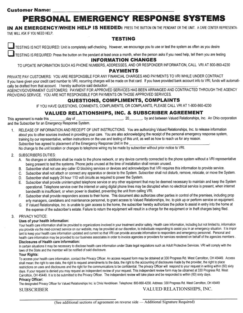
43 Customer Name: MONITORING SERVICES INFORMATION AND RELEASE QUESTIONS, COMMENTS, COMPLIMENTS, COMPLAINTS IF YOU HAVE QUESTIONS, COMMENTS, COMPLIMENTS, OR COMPLAINTS, PLEASE CALL VRI AT I MONITORED MEDICATION MANAGEMENT SYSTEMS I hereby authorize Valued Relationships Inc., ( VRI ) to install a monitored Medication Management System consisting of a medication dispenser, a Personal Emergency Response System (PERS) or any other communication device in my home that may be necessary to transmit information from the medication dispenser to the monitoring center. I understand that my caregiver or myself are responsible for refilling the medication dispenser and/or reprogramming the dispensing unit on an on-going basis. I understand that neither VRI nor its representatives are responsible for refilling the Medication Management System or reprogramming the unit based on changes in my medication and/or my medication schedule. I further understand that the Medication Management System is designed to remind me to take my medications, and that VRI is not responsible for my failure to so, whether as a result of a malfunction of the Medication Management System or otherwise. Additionally, I understand that my Medication Management System will automatically communicate with a 24 hour monitoring center via telephone, internet, SMS, wireless or other communication methods, in order to report certain conditions. I understand that these communication methods may not be secure and that the transmission of this information is not a violation of my privacy. The Medication Management Systems has been tested in my home, and I agree not to relocate the unit or alter any of the communication devices, networks or systems, as it may affect the functionality and operation of the Medication Management System. I accept responsibility for contacting VRI should I require additional instruction on the use or functions of the Medication Management System. Either myself, my caregiver, or both understands the operations of the system and has reviewed and complied with the following: Member and/or Caregiver is responsible for filling and programming the Medication Management Systems Member and/or Caregiver has been instructed in the use of the Medication Management System Member and/or Caregiver understands not to move, disconnect, or alter the communication networks of Medication Management System System QUESTIONS, COMMENTS, COMPLIMENTS, COMPLAINTS IF YOU HAVE QUESTIONS, COMMENTS, COMPLIMENTS, OR COMPLAINTS, PLEASE CALL VRI AT I CELLULAR BASED SOLUTIONS I acknowledge and understand that the use of cellular based solutions for Personal Emergency Response Systems includes additional risks associated with the quality and reliability of cellular signals and service. Cellular communications are affected by a number of factors outside the control of VRI and may be impaired or blocked by building construction style, building materials, atmospheric conditions (i.e. weather), distance from transmitter to receiver, surrounding terrain, battery life, signal strength, cellular network traffic, cellular tower condition and interference from other cellular devices. I also understand that cellular based solutions rely on third party services from wireless carriers such as AT&T, Alltel, Cingular, Sprint, T-Mobile, and Verizon that are not controlled by VRI or its representatives. I acknowledge that even if cellular solutions work well at the time of installation or activation, I am responsible for monitoring signal strength, power, and service quality on an on-going basis. VRI is not responsible for maintaining or monitoring the networks used for communication, and can only provide timely and accurate response if all equipment and networks are working correctly and providing adequate signal strength. Users of cellular based solutions should test their equipment on a regular basis to identify any deterioration of network service and signal strength. I also acknowledge and understand that there may be additional issues related to sending information from the Personal Emergency Response System to the monitoring center over cellular networks beyond what is mentioned here. I further understand that technology used for cellular communications can fail at any time, and I release VRI, its staff, employees, owners, shareholders, officers, contractors, representatives and vendors from any and all liability related to the transmission of emergency signals or communications over cellular networks. GPS LOCATION TECHNOLOGY AND SERVICES I understand that certain solutions for mobile Personal Emergency Response Systems utilize the Global Positioning System (GPS) to provide location data. I acknowledge that GPS location tracking is reliant on third party technologies that are not under the control of VRI. Any failure of these third party technologies or third party services could result in an inability to provide mobile PERS or GPS location tracking by VRI. Customer will hold VRI harmless for any failures by third parties that impact its ability to provide service. GPS is a satellite navigation system that can determine a device s location by measuring the distance between itself and three or more GPS satellites. VRI uses commercially available technology and U.S. Government owned satellites to generate location data for any GPS device that it monitors. I acknowledge and accept that the use GPS location technology includes a number of inherent risks, including but not limited to: Obstructions (such as buildings) can prevent satellites from accurately locating the GPS device Currently available GPS technology is only accurate to within 50 feet of the actual location Transmission requires power from the device s battery, so a low or defective battery may prohibit accurate transmission of location data Damage to the device or antenna could prevent accurate transmission of location data GPS satellites are controlled by the government and any restriction or reduction of service could limit GPS access to location information I also acknowledges that using GPS tracking and location data may require VRI to disclose the location of the mobile PERS device to responders including police, fire, EMS and individual responders (such as family or caregivers) identified by the customer. Customer assumes the potential risks of releasing said location information and waives any and all claims related to privacy laws, including HIPAA, and any direct or indirect damages related to release of such information. I acknowledge that I have read the above and fully understand it. I further acknowledge that there are other risks involved in using the GPS tracking and location technology and services beyond what is detailed herein. Furthermore, I release VRI, its staff, employees, owners, shareholders, officers, contractors, and vendors from any and all liability in regards to the transmission of an emergency signal, location information or communication over the cellular network and Global Positioning System (GPS). SUBSCRIBER VALUED RELATIONSHIPS, INC.
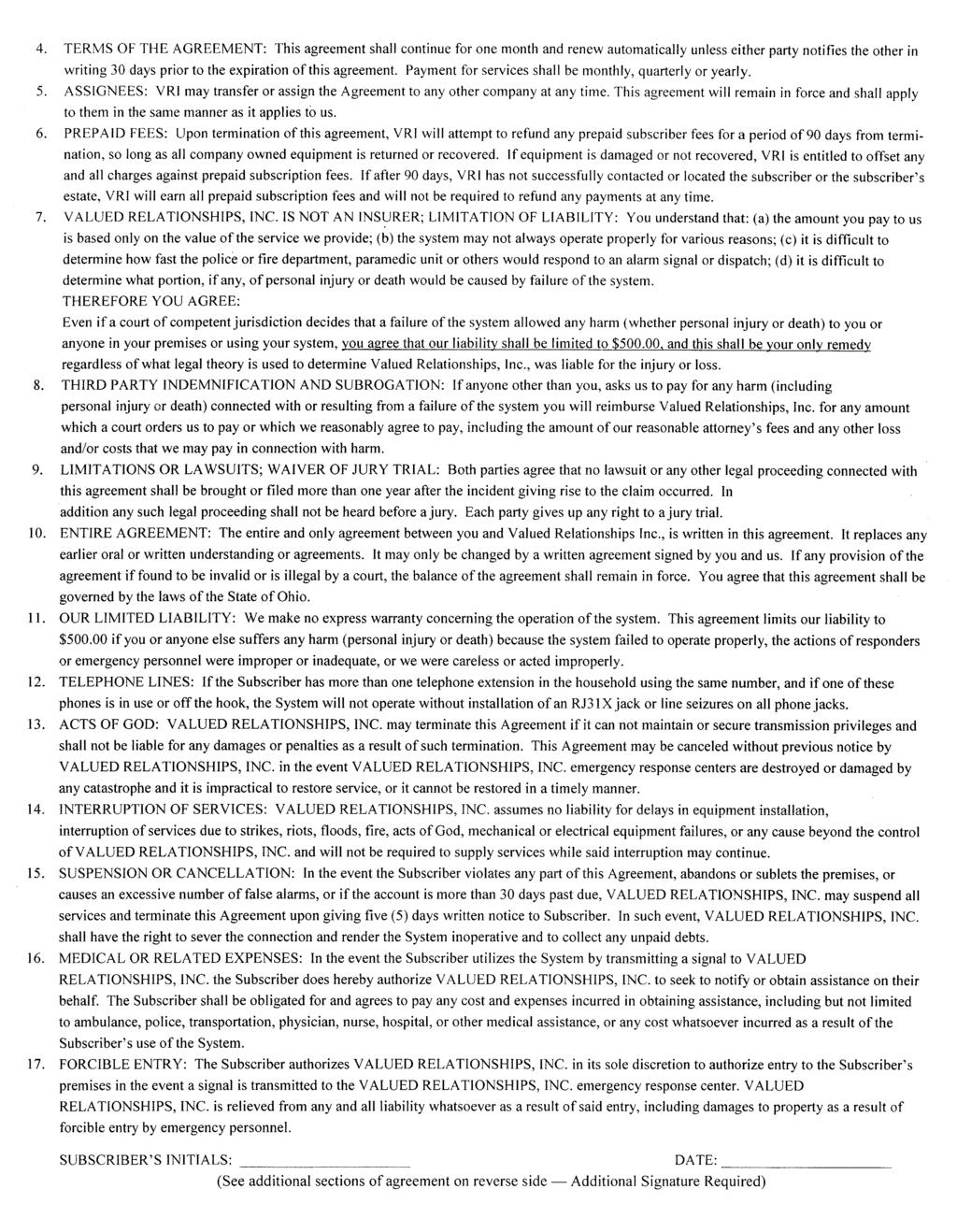
44 MONITORING SERVICES INFORMATION AND RELEASE BROADBAND, DIGITAL PHONE AND VOICE OVER INTERNET PROTOCOL (VoIP) SERVICE I acknowledge that VRI and/or its representatives has explained the additional risks associated with using broadband phone, digital phone or voice over internet protocol (VoIP) services in association with Personal Emergency Response Systems. These risks include, but are not limited to loss of phone service due to power failure, loss of phone service from damaged or faulty modem equipment, failed communication or data transmission due to inadequate bandwidth or bandwidth management, loss of service due to atmospheric conditions (i.e. weather), and network disruption or data loss during transmission over digital networks. I acknowledge that digital phone and VoIP services are reliant on third party technologies that are not under the control of VRI. Any failure of these third party technologies or third party services could result in an inability to provide timely and adequate response by VRI. Customer will hold VRI harmless for any failures by third parties that impact its ability to provide service. I also understand that even if digital or VoIP solutions work well at time of installation or activation, I am responsible for monitoring signal strength, equipment function, power/battery, and service quality on an on-going basis. VRI is not responsible for maintaining or monitoring the reliability of the networks used for communication, and can only provide a timely and accurate response if all equipment and networks are working correctly and providing adequate signal strength and complete data transmission. Users of digital and VoIP solutions should test their service on a regular basis to identify any problems or deterioration of network service and signal strength. I also certify that I will not use any caller ID blocking equipment or services at any time. I also acknowledge and understand that there may be additional issues related to sending information from the Personal Emergency Response System to the monitoring center over digital or VoIP networks beyond what is mentioned here. I further understand that technology used for digital and VoIP communications can fail at any time, and I release VRI, its staff, employees, owners, shareholders, officers, contractors, representatives and vendors from any and all liability related to the transmission of emergency signals or communications over digital and VoIP networks. In response to the increased risks associated with using digital phone or VoIP service, VRI provides additional service options (listed below). I acknowledge that I have been informed of these options and understand the risks and ramifications of my choice of service. Option 1: Personal Emergency Response System programmed specifically for use with broadband based dial-tone (VoIP service) This service option is available if the equipment type used by the subscriber or required by the agency is capable of performing two sepa rate actions based on the type of communication required. However, it must be chosen at the time of installation to allow for special pro gramming and set-up by VRI and its representatives. This option reduces the risk of data loss or transmission failure due to band width management, but does not eliminate the risks associated with loss of power, loss of phone service or damage to modem equipment. Option 2: Personal Emergency Response System plugged into adaptive device to bypass broadband based dial-tone (VoIP service) This service option requires an additional adaptive device and uses a high speed internet connection to bypass the use of digital or VoIP services. The additional equipment and service requires payment of additional fees and the acceptance of risks associated with data trans mission over a high speed internet connection. This option does not allow PERS equipment to report maintenance alarms such as low bat tery or A/C power failure. This option alerts the monitoring center when internet communication service is not available or power is lost, but does not eliminate risks associated with loss of phone service or damage to modem equipment. Option 3: Personal Emergency Response System plugged directly into subscriber s broadband based dial-tone (VoIP service) This service option does not require any special equipment or programming. This option relies completely on the reliability and success of the third party networks providing digital phone and VoIP services for transmission of emergency signals and data. This option does not eliminate the risks associated with loss of phone service due to power failure, loss of phone service from damaged or faulty modem equip ment, failed communication or data transmission due to inadequate bandwidth or bandwidth management, loss of service due to atmos pheric conditions (i.e. weather), and network disruption or data loss during transmission over digital networks. The client acknowledges that they have read the above and fully understand it. Customer further acknowledges that there may be other issues involved in sending information from the emergency unit to the monitoring center even beyond what is mentioned here and that the technology is yet unproven and releases VRI, its staff, employees, owners, shareholders, officers, contractors, and vendors from any and all liability in regards to the sending of a help signal over digital phone or VoIP networks and their supporting systems. HIGH SPEED INTERNET OR DSL BASED SOLUTIONS I acknowledge and understand that the use of high speed internet or DSL based solutions for Personal Emergency Response Systems includes additional risks associated with the quality and reliability of network connections, signal integrity and service levels. Internet communications are affected by a number of factors outside the control of VRI and may be impaired by distance from transmitter to receiver, signal strength, network traffic, damage to network equipment and interference from other devices. I also understand that internet based solutions rely on third party technologies and services that are not under the control of VRI or its representatives. Any failure of these third party technologies or third party services could result in an inability to provide services by VRI. Customer will hold VRI harmless for any failures by third parties that impact its ability to provide service. I also understand that even if internet based solutions work well at time of installation or activation, I am responsible for monitoring signal strength, equipment function, and service quality on an on-going basis. VRI is not responsible for maintaining or monitoring the reliability of the networks used for communication, and can only provide a timely and accurate response if all equipment and networks are working correctly and providing adequate signal strength and complete data transmission. Users of internet based solutions should test their service on a regular basis to identify any problems or deterioration of network service. I also acknowledge and understand that there may be additional issues related to sending information from the Personal Emergency Response System to the monitoring center using internet based solutions beyond what is mentioned here. I further understand that technology used for cellular communications can fail at any time, and I release VRI, its staff, employees, owners, shareholders, officers, contractors, representatives and vendors from any and all liability related to the transmission of emergency signals or communications over cellular networks. SUBSCRIBER S INITIALS: DATE: (See additional sections of agreement on reverse side Additional Signature Required)
45 Safety Independence Peace of Mind Solutions, Brochures, Marketing and Misc Info (These are also available on the Dealer Website) Bringing You Safety, Independence and Peace of Mind fax


46 Introducing VRI s Monitoring Solutions VRI is an independent, privately owned, solution driven verses product driven provider that delivers monitoring solutions nationwide through a network of home service representatives and independent dealers. PERS or Medical Alert: 2-way voice, auto-tested communicator that is activated by a waterproof help button that can be worn either on a neck cord or wrist strap and sends a signal through a standard phone line. VRI utilizes different models to provide solutions to different needs. These units also give us a variety of signal range and back-up battery capacities. If the radio frequency of the unit does not allow a satisfactory range, we have other options so we do not have to settle for a limited range that could possibly place the consumer at risk. Help buttons that can be easily activated but designed so there are few accidental activations which tends to increase compliance. Our monitoring includes Care Calls. These are preventative calls for added peace of mind. We are not limited to emergencies! We provide medial alert monitoring only. Our Care Center is 5-diamond certified by the Central Station Association of America. It is the sole medical alert only provider that has obtained this certification. We provide closed-looped monitoring which means that we do not assume the promised help arrives; we follow-up. Incident reports are sent by fax or to notify the referring agency. MedConnect Access Card: This solution provides a secure place to store a list of medications, prescribed and over-the-counter, so the consumer can maintain an up-to-date record. This solution requires caregiver assistance to complete the data entry. MedReady Medication Dispenser: Helps our members get the right dose at the right time! Holds 28 doses, can dispense up to 4 times per day, and can be monitored by a VRI400 Medical Alert. Options: Monitored or Non-Monitored Active or Inactive Monitoring Monitored by a VRI400 PERS or a modem Red light for hearing impaired A VRI400 PERS can monitor up to 6 dispensers. IMD.2 Medication Dispenser: Limited Availability Provides another solution for someone needing assistance with medication compliance but is taking larger doses and needs additional reminders during or between doses. Holds up to 60 doses and can dispense up to 6 times per day. Bringing you Safety, Independence and Peace of Mind ~ fax


47 Fall Alert Device or Fall Monitoring: Limited Availability A simple device that is worn like a pager to assist those who fall with no precursor warnings. This device contains a package of accelerometers that monitors the movement of the body and automatically activates a transmitter to summon help. DigiCare Medical Alert: Cable TV / Digital Compatible 2-way voice communicator that is compatible to digital phones that are provided through cable TV and VOIP providers. This devise removes the risk of dropped calls due to the way a medical alert transmits data to a central monitoring station. A standard medical alert may work some the time with a digital system but not always. Care Connect: Internet Compatible A standard medical alert signal is not compatible to the digital signal provided by cable TV or Internet phone providers resulting in dropped calls or hang ups. Care Connect is a VoIP router that contains software that converts a standard phone signal to a digital signal. Special Adaptive Switches: A solution for those who lack the dexterity or physical mobility to activate a standard help button. These include plate switches, sip-n-puff, toggle, and pillow switches. Soft touch buttons are also available. Monitored Smoke Detectors: According to NFPA, 80% of fire deaths occur in the home. This is a perfect solution for someone who forgets to turn off the stove or smokes in the bed. When our Care Center receives a signal, the local Fire department is notified Immediately unless the consumer clearly communicates that it is not an emergency. Steel Key Lock Box Seconds can be the difference between life or death in an emergency. This solution provides a secure place to store an entry lock key. Boundary Alerts This solution provides comfort to a caregiver of a patient who wanders. It is an in-home alarm that alerts the caregiver when the patient is exiting the residence. Bringing you Safety, Independence and Peace of Mind ~ fax

48 HELPING YOU STAY AT HOME LONGER! Your independence and peace of mind are very important to you. They are also important to us. We strive to match user-friendly electronics with our devoted response center in an effort to reduce hospitalization and nursing home placement. Whether it's a voice personal response system or a medication reminder dispenser, we make it easy with one simple call to our toll-free number. Just consider some of the benefits we include in our service. Dedicated service personnel who service in the home, not my mail. A wide variety of waterproof buttons, wrist, necklace and clip-on's. Our Monitoring Center can speak languages other than English if needed. The ability to answer incoming calls with portable help buttons. Automatic testing units, confirming the connection of the service. Reports of all help calls in an easy to read summary format. Care calls we're not just for emergencies! Personal Response Service - Assistance at the touch of a button anytime. Medication Compliance - Take the right dose at the right time. Fall Alert - Special Device, which alerts the response center when a fall occurs. Boundary Unit - Notifies caregiver when the patient is exiting the home. Special Activation Devices for Personal Response - To help the physically challenged utilize our services. Telehomecare - Vital sign and general health condition monitoring which allow family or caregivers to monitor health condition remotely and daily. Phone Strobe - Notifies you when the phone is ringing. "For elderly people who live alone, becoming incapacitated and unable to get help is a common event, which usually marks the end of their ability to live independently." - Southern Medical Journal 1995 "When indicated by a patient's health status and social circumstance, recommending a personal emergency response system might be the appropriate environmental prescription." - N. Engl J Med 1996 Call Us Today! Contact information on back. Dealer info area


49 Medical Alert Systems MedConnect Store your medication information online Association of American Physicians and Surgeons, Inc. recommendations: Keep your doctor advised of all medications. Make a list of all medications, vitamins, and supplements. The list should include name, use, dosage, and how often you really take every pill, tablet, etc. Update the list every time you see a new doctor; change, add, or subtract medications, and alter dosages. Make sure your physician sees your list with each visit. Your physician should keep a copy of the medication list. Try to minimize the John Q Patient Medication list at Username: Password: Please see the instructions on the reverse side For information on this or other services please call. MedConnect Access Card What do the physicians say? Your Medication Information in One Single, Safe Location Easy for Your Doctor, Pharmacist or Caregiver to Access Included with a subscription to our PERS service at no charge. FREE! number of pharmacies used and keep your pharmacist up to date. This is where MedConnect comes in... After entering your current medication information, show your MedConnect Access Card to your doctor, pharmacist, or caregiver. They will easily view your medication list online and make sure you re receiving the proper care. It s that easy! Medical Alert Systems The Care Center Care the essence of what we provide. Whether getting assistance, providing reassurance, or just a friendly voice, we re there when others can t be, and happy to speak with a member anytime. Center because we are at the center of getting information to all the parties involved in keeping our members safe and at home, where they are most happy. You can have confidence the Care Center will be there when you need it because we designed it to incorporate the latest equipment and services from the leading companies in telephony and data processing. Contact your local dealer for more information An authorized dealer of Medical Alert Systems SAFETY PEACE OF MIND INDEPENDENCE


50 Medical Alert Systems the right tools Medication Management How it works Alarm sounds when dose is ready, if not taken, unit will contact Care Center. 1 Simple & Reliable 1. Load 2. Set clock 3. Program alarm 4. Close Here s how it works When the time comes to take your next dose, the alarm will sound and the dose will rotate into position. The alarm stops when the dose is taken out. If the dose is not removed within 30 minutes, the unit can contact the 24-hour Care Center which then attempts to alert someone of a non-compliance event. It s really that easy! ALWAYS 24/7 AC T I V E every dose on time Simple-to-use cups no hard to open pill bottles or boxes. Ed this is the Care Center it s time to take your medication. 2 3 Oh, OK thanks for the reminder, I guess I didn t hear it and was so busy I didn t realize it was time to take my pills out of the machine. Thanks so much, I ll go in and take them right now. Lots of Prescriptions? Keeping up with a lot of prescriptions can be a real challenge. There may be one set of pills and vitamins to be taken in the morning, another set to be taken throughout the afternoon, and still other pills before bed. Now there s an easier way to manage all those pills. The MD.2 simplifies everyday medication management, giving you more time and freedom. It is simple and reliable, and the convenient medication dispensing MD.2 cups are much easier to open than a pill box or prescription bottle. Our goal has always been to keep people safe and independent as long as possible. Helping people manage their prescription therapies more effectively is key to accomplishing that goal. You ll have fewer worries about Forgetting to take a dose Taking a double dose Taking at the wrong time Indentifying pills or pill bottles for people with decreased vision Opening and closing pill bottles Privacy regarding the type and quantity of medication


51 Medical Alert Systems the right tools easy-to-use Personal Response Service How it works 1 Simply Push Button and speak to the Care Center Mary, this is the Care Center, your mom has fallen outside, are you able to go over and help her? A Medical Alert System in your home means that we re there to help with just the touch of a button. I ve got someone at the door and wasn't expecting visitors, can you listen while I see who it is? 1...thanks for calling, I'll go over and check on mom right now. I ll press the button when I arrive. The HELP Button Smallest available. Comfortable & Convenient. Waterproof design. reliable 3 2 ALWAYS 24/7 AC T I V E Mom s just fine, thanks to you and her button, she should be back in the garden tomorrow if not sooner! That s what we re here for. Glad to hear everything s ok. Call us anytime. No Long Term Agreements No equipment to purchase Friendly local staff No hidden charges The peace of mind, security, and confidence to continue with daily activities and maintain your independence can be yours with the high quality Personal Response System (also known as a Medical Alert System) that is affordable and easy to use. 2 Oh it s just my granddaughter, so nice of her to visit. affordable We ll stay right here while you check. Great Martha, enjoy the visit, if you need us again just press your button, have a great day now.


52 Medical Alert Systems Medication Compliance Why is it important? Almost 30% of all hospital admissions for people over the age of 65 are directly attributable to medication non-compliance. 125,000 people die each year from non-compliance, twice the number killed in automobile accidents. Poor compliance with medication regiments costs society $150 billion per year. Nearly $48 billion in annual costs result from unnecessary medication-induced hospitalization. Approximately 40% of people entering nursing homes do so because they are unable to selfmedicate in their own homes. About one-half of the 1.8 billion prescriptions dispensed annually are not taken correctly, contributing to prolonged or additional illnesses. At the present time, more than 7 million households have an unpaid care-giver who is providing daily assistance to a family member age 50 or older. Medical Alert Systems The Care Center Care the essence of what we provide. Whether getting assistance, providing reassurance, or just a friendly voice, we re there when others can t be, and happy to speak with a member anytime. Center because we are at the center of getting information to all the parties involved in keeping our members safe and at home, where they are most happy. You can have confidence the Care Center will be there when you need it because we designed it to incorporate the latest equipment and services from the leading companies in telephony and data processing. Contact your local dealer for more information Medical Alert Systems SAFETY PEACE OF MIND INDEPENDENCE Archives of Internal Medicine 1990; 150: A. Anderson, Update on Patient Non-Compliance NPC Report Archives of Internal Medicine- October 1995 Feasibility Study, Biomedical Business International, January 1988 Medications and the Elderly, Ch.4 pp 67-68, 75 Family Circle 6/25/91, pp. 46 An authorized dealer of

53 LANGUAGE LIST Afrikaans Akan Albanian Algerian Amharic American Sign Language Anuak Arabic Armenian Ashanti Assyrian Azerbaijani Badini Bajuni Bambara Basque Behdini Belorussian Bengali Berber Bosnian Bulgarian Burmese Cantonese Catalan Chaldean Chaochow Chamorro Chavacano Chuukese Creole Croatian Czech Dakota Danish Dari Dinka Dutch Eritrean Estonian Ewe Farsi Fijian Hindi Finish Flemish French French Canadian Fukienese Fula Fulani Fuzhou Ga Gaelic Georgian German Gorani Greek Gujarati Haitian Creole Hakka Hakka China Hakka - Taiwan Hausa Hebrew Hindi Hmong Hungarian Ibanag Ibo Icelandic Igbo Ilocano Indonesian Italian Jakartanese Japanese Javanese Karen Kashmiri Khmer (Cambodian) Kinyarwanda Kirundi Korean Kosovan Kreo Krio Kurdish Kurmanji Lakota Laotian Latvian Lebanese Lingala Lithuanian Luganda Lusoga Luxembourgeois Maay Macedonian Malagasy Malay Malayalam Maltese Mandarin Mandingo Mandinka Mankon Marshallese Mien Mina Mirpuri Mixteco Moldovan Mongolian Navajo Ndebele Neapolitan Nepali Nigerian Pidgin English Norwegian Nuer Oromo Papiamento Pashto Patois Persian Pidgin English Polish Portuguese Portuguese Creole Pothwari Punjabi Romanian Russian Samoan Serbian Shanghainese Shona Sicilian Sinhalese Sindhi Slovak Slovenian Somali Sorani Spanish Sri Lankan Swahili Swedish Sylhetti Szechuan Tagalog Taiwanese Tamil Telugu Thai Tibetan Tigre Tigrinya Toishanese Tongan Tshiluba Turkish Twi Ukrainian Urdu Vietnamese Visayan Welsh Wolof Yiddish Yoruba Yupik These 173 languages represent approximately 98.6% of all customer requests from the 6,809 languages spoken in the world today. We monitor our language requests continuously, adding or deleting languages based upon customer needs Language Line Services Lower Ragsdale Drive, Bldg. 2 Monterey, CA

54 Safety Independence Peace of Mind Manuals and Technical Info This section is a representation of equipment and devices that are available to you. A complete compilation of product manuals are available on the Dealer Website Bringing You Safety, Independence and Peace of Mind fax
 MODEL: VRI400 January 2000 (800)")
55 VRI400 TECHNICAL OPERATIONS GUIDE Power Light Phone Light Test Light Home Light Away Light Help Button Help Light Personal Help Button (PHB) MODEL: VRI400 January 2000 (800)
56 TABLE OF CONTENTS 1.0 Welcome to VRI Installation Typical Installation Installation with Multiple Telephone Devices Installation with DSL Service Service Options Quick Start Calling for Help Monthly Testing Information Updates Using Your Personal Help Button Additional Personal Help Buttons Using the Console Help Button Using the VRI400 Check-In Feature (Optional) Using the Inactivity Timer Feature (Optional) Automatic Test Features Using the Automatic Voice Test Feature (Recommended Option) Using the Automatic Dial Test Feature (Option) Controls Power Switch Home/Away Slide Switch Cancel Button Test/Learn Button Learning Personal Help Buttons Range Test Mode
57 9.4.3 Monitoring a Test Call Internal Backup Battery AC Power Monitoring (Optional) Status Lights POWER PHONE TEST HOME AWAY HELP Troubleshooting User Responsibilities Message Summary Accessories Service Warranty NOTES NOTIFICATIONS
58 1.0 Welcome to VRI400 Congratulations! You have chosen the most advanced and reliable Personal Emergency Response System available to provide you comfort and peace of mind. Help is just one touch away! Pressing your waterproof Personal Help Button will immediately activate the VRI400. Within seconds, the Response Center will be notified that you need assistance. A caring and professionally trained Care Assistant will talk to you through the VRI400 speakerphone. The friendly Care Assistant will telephone your friends, neighbors, family or authorities based on the type of assistance you need. If you cannot hear the Care Assistant, do not worry, help will automatically be summoned. VRI400 is fast and simple to connect to your telephone. A Service Provider usually connects the VRI400; however, you may elect to do it yourself. In either case, the Subscriber Information Form must be completed with your name, address, responder names and any important medical information that would be helpful to the Care Assistant. 2.0 Installation Your VRI400 should be installed in an area that is free from sources of loud noise. The location should be in a central part of the home that is used frequently and near a telephone jack and AC electrical outlet. When your VRI400 calls the Response Center, the telephone and any other device connected to the PHONE jack on the rear of your VRI400 will be disconnected during the call. This means that if this telephone is off-hook, your VRI400 can still contact the Response Center. If there are other extensions of the same telephone number in your home that are off-hook when your VRI400 needs to place a call, it will not be able to unless the local telephone company has installed an RJ31X jack. This allows the VRI400 to disconnect any telephone in the house that may be off-hook. If you elect to have an RJ31X jack installed, contact your Service Provider and ask for an RJ31X telephone cord, part number RA400-RJ31X. When connecting multiple devices such as a telephone, answering machine, Caller-ID, etc. along with your VRI400 to the same telephone wall jack (see Figure 2), it is important that your VRI400 be the only device connected directly to the telephone wall jack. 1
59 2.1 Typical Installation (Refer to Figure 1 below for the following instructions.) 1. Locate a telephone jack with an electrical outlet nearby. The VRI400 should be placed on a flat horizontal surface. The VRI400 should be located away from the immediate vicinity of mechanical noises, i.e. oxygen generators, electrical equipment such as televisions and radios. 2. Unplug the phone cord from the wall jack and plug it into the jack on the rear of the VRI400 marked PHONE. 3. Find the phone cord supplied with the VRI400. The connector on one end of the cord is larger than the connector on the other end. Plug the larger connector into the jack on the rear of the VRI400 marked WALL. Plug the smaller end into the telephone wall jack. 4. Plug the power cube into the electrical outlet. Verify that the outlet is NOT controlled by a light switch. 5. Turn the Power Switch on that is located on the rear of the VRI Perform the Range Test as described in Section Call the Response Center and provide the Care Assistant with your Responder Information and to perform an initial Customer Test. Electrical Outlet Power Cube PHONE WALL Wall Jack Telephone Figure 1: Typical Installation Rescue VRI400Alert 2
60 2.2 Installation with Multiple Telephone Devices (Refer to Figure 2 below for the following instructions.) 1. Locate a telephone jack with an electrical outlet nearby. The VRI400 should be placed on a flat horizontal surface. The VRI400 should be located away from the immediate vicinity of mechanical noises, i.e. oxygen generators, electrical equipment such as televisions and radios. 2. Unplug the cord from the wall jack and plug it into the jack on the rear of the VRI400 marked PHONE. 3. Find the phone cord supplied with the VRI400. The connector on one end of the cord is larger than the connector on the other end. Plug the larger connector into the jack on the rear of the VRI400 marked WALL. Plug the smaller end into the telephone wall jack. 4. Plug the power cube into the electrical outlet. Verify that the outlet is NOT controlled by a light switch. 5. Turn the Power Switch on that is located on the rear of the VRI Perform the Range Test as described in Section Call the Response Center and provide the Care Assistant with your Responder Information and to perform an initial Customer Test. Electrical Outlet Power Cube PHONE WALL Wall Jack Telephone Rescue VRI400 Alert Caller ID or Answering Machine Figure 2: Installation with Caller-ID or Telephone Answering Machine 3
61 2.3 Installation with DSL Service In order to have functional service, homes with DSL telephone/computer service require additional installation steps. Below we have listed the three configurations for a successful VRI400/DSL installation in order of commonality. Even with these configurations, it is possible that you will need to call Customer Service for a more extensive troubleshoot A self-installed DSL filter, supplied by the DSL provider, is installed on the telephone cord, between the VRI400 and the wall jack. Illustrated below The DSL filter is hard wired by the DSL provider. In this instance the home does not have self-installed filters on the telephone jacks, and the VRI400 will be a standard hook-up. Illustrated below If neither of the above configurations works, you may be able to connect the VRI400 into the DSL modem, by the computer. Illustrated below. 4
62 2.4 Service Options Your VRI400 operation can be customized to fit your needs. For example, you may need to dial 9 to make a telephone call from your home. The VRI400 must do the same. Once your VRI400 is set to dial 9, you may write the special dialing information on the bottom of your VRI400 in pencil. Your Check-In times are another example of service options that you may want to keep track of on the bottom of your VRI400. Additional service options that are programmed into your VRI400 can be written on the bottom for future reference. Contact your Service Provider for additional information. If you have two or more telephone extensions on the premises using the same telephone number, and if one of these telephones is off hook or otherwise in use, the VRI400 will not operate without installation of an RJ31X connection by the telephone company. It is your responsibility to have this device installed if so desired. Signals are transmitted using electrical power and over telephone company lines which are wholly beyond the control and jurisdiction of Response Center or Service Provider and in the event the telephone service is out of service or disconnected, the VRI400 will not operate. Furthermore, the Response Center or the Service Provider are not responsible for any monitoring during periods when Response Center s telephone lines are not working, or under any condition which would make it impossible to send a normal telephone call from the Response Center s place of business. 3.0 Quick Start Once your VRI400 is connected to the telephone line and your subscriber information is given to the Response Center, help is just one touch away! 3.1 Calling for Help To summon help, simply press your Personal Help Button. Your VRI400 will start beeping. Within seconds, you will hear a friendly Care Assistant through your VRI400. If you are able to reply, tell the Care Assistant what you need and your will be taken care of. Help can also be summoned by pressing the blue Help Button on the front of your VRI400. If you cannot reply, do not worry, help will automatically be summoned. 5
63 3.2 Monthly Testing At least once every month you should perform a test call to the Response Center to assure that your VRI400 is functioning properly. Simply press your Personal Help Button. Within seconds, a friendly Care Assistant will ask if you need help. Tell the Care Assistant that you are performing a test and do not require any assistance. 3.3 Information Updates Please inform the Response Center of any changes that are pertinent to your receiving help. Changes may include responder names or phone number changes, area code changes, additional responders, a change in your medical or household status, etc. 4.0 Using Your Personal Help Button Your VRI400 is supplied with one waterproof Personal Help Button on a neckcord. If desired, your Service Provider can replace the neckcord with a wristband. Your Personal Help Button uses an indicator light to show the status of its internal battery. While your Personal Help Button is being pushed, the light on the Personal Help Button is green to indicate the internal batteries are good. A red light indicates the internal batteries are becoming weak. In between use, the internal batteries can rejuvenate. As a result the light may not be red the next time your Personal Help Button is activated. When the light is red most of the time, your Personal Help Button should be replaced within six months. When any learned Personal Help Button is activated within the effective operating range, the VRI400 will automatically dial the Response Center. Within seconds, a professionally trained and friendly Care Assistant will speak to you through your VRI400. If help is needed, the Care Assistant will call responders from the Responder List that you provide. 4.1 Additional Personal Help Buttons Your VRI400 is supplied with one waterproof Personal Help Button. In homes where more than one person wishes to wear a Personal Help Button, or you wish to have additional buttons, you may ask your Service Provider to supply you with up to eight buttons. If you are using more than one Personal Help Button, you have the choice of using the same Responder List for all buttons or having a separate Responder List for each button. The Response Center will know which Personal Help Button was pressed and will call responders from the Responder List that you provided which is associated with that Personal Help Button. Your VRI400 is designed to provide for your peace of mind and comfort within the privacy of your home and yard. The signal from the Personal Help Button is limited by various factors and may vary from home to home. It is your responsibility to know the effective operating limits of your Personal Help Button and to use it within these limits. Please contact your Service Provider for additional information. 6
64 5.0 Using the Console Help Button When the blue Help Button on the front of your VRI400 is pressed, a He lp Needed message is sent to the Response Center. Within seconds, a professionally trained and friendly Care Assistant will speak to you through your VRI400. If help is needed, the Care Assistant will call responders from the same Responder List as the main Personal Help Button unless instructed otherwise. 6.0 Using the VRI400 Check-In Feature (Optional) Your VRI400 can be set to provide for your assistance even when you are unable to get to a telephone or push your Personal Help Button. Using the Check-In feature allows the Response Center to automatically check on you if you fail to respond to your VRI400 Check-In request. Your VRI400 can be set to Check-In with you up to five specific times each day. At each specified time, your VRI400 will sound a series of long and short beeps. You will have a few minutes to tell your VRI400 that everything is okay by pressing your Personal Help Button, Console Help Button, Cancel Button or the Test/Learn Button. If you do not respond, your VRI400 will send a Check-In message to the Response Center. If the Check-In feature is enabled, be sure to leave the Home/Away Switch in the Away position when you are not at home to prevent your VRI400 from sending false Check-In messages to the Response Center. The Check-In and Inactivity Timer features cannot be enabled at the same time. For more information or help in setting the VRI400 Check-In feature, please contact your Service Provider. 7.0 Using the Inactivity Timer Feature (Optional) Your VRI400 can be set to provide for your assistance even when you are unable to get to a telephone or push your Personal Help Button. Using the Inactivity Timer feature allows the Response Center to automatically check on you if you fail to reset your VRI400 Inactivity Timer. Your VRI400 Inactivity Timer can be set in increments of 30 minutes. Most users prefer to use either a 12-hour or 24-hour timer. Pressing your Personal Help Button, the red Cancel Button, using your telephone, sliding the Home/Away Switch or pressing the Test/Learn Button resets the Inactivity Timer. If the Inactivity Timer is not reset before the time-out period, your VRI400 will sound a series of long and short beeps. You will have a few minutes to tell your VRI400 that everything is okay by pressing your Personal Help Button, Console Help Button, Cancel Button or the Test/Learn Button. If you do not respond, your VRI400 will send an Inactivity message to the Response Center. If the Inactivity Timer feature is enabled, be sure to leave the Home/Away Switch in the Away position when you are not at home to prevent your VRI400 from sending false Inactivity messages to the Response Center. The Inactivity Timer and Check-In features cannot be enabled at the same time. For more information or help in setting the VRI400 Inactivity Timer feature, please contact your Service Provider. 8.0 Automatic Test Features Your VRI400 is designed to perform two automatic tests, described below, that result in messages being sent to the Response Center. Both tests are optional and either one or both may be utilized. The Automatic Voice Test provides the most complete test and is typically enabled by the manufacturer. The Automatic Dial Test is less intrusive but does not test your Personal Help Button, or the speaker and microphone circuits in your VRI400. The manufacturer typically disables the Automatic Dial Test. It is strongly recommended that you use the Automatic Voice Test feature described below. If you do wish not to use this feature, it is highly recommended that you at least use the Automatic Dial Test. 7
65 The automatic tests are typically performed every 25 days. If desired, your VRI400 can be set to perform these as often as you wish - even daily. Contact your Service Provider for more information. 8.1 Using the Automatic Voice Test Feature (Recommended Option) Many VRI400 subscribers prefer to use the Automatic Voice Test Feature offered by your VRI400 because of the added safety and peace of mind that it provides. Almost every circuit of your VRI400 is tested including the microphone, speaker and Personal Help Button. When the Automatic Voice Test Feature is enabled, your VRI400 will automatically send an Automatic Voice Test message to the Response Center. The Care Assistant will greet you, ask you to press your Personal Help Button, tell you that your VRI400 is working properly and ask if you have any questions. Your VRI400 automatically sends the test message to the Response Center during daytime hours. If your telephone is being used, your VRI400 waits until the line is available. Your Service Provider can set how often your VRI400 sends the test message. 8.2 Using the Automatic Dial Test Feature (Option) If the Automatic Voice Test is not used, it is strongly recommended that you use the Automatic Dial Test Feature offered by your VRI400. This test verifies the ability of your VRI400 to deliver a message to the Response Center. When the Automatic Dial Test Feature is enabled, your VRI400 will automatically send an Automatic Dial Test message to the Response Center. If the Response Center does not receive an expected test call from your VRI400, the Care Assistant will contact your Service Provider to help determine the cause Your VRI400 automatically sends the test message to the Response Center during midnight hours. If your telephone is being used, your VRI400 waits until the line is available. Your Service Provider can set how often your VRI400 sends the test message. 9.0 Controls Your VRI400 uses various switches and buttons to operate or control its function. Each is described below. For additional information, contact your Service Provider. 9.1 Power Switch Your VRI400 s Power Switch is located on the rear of your VRI400. To turn your VRI400 on, the power cube must be connected to an active AC outlet. Even though your VRI400 has an internal battery, your VRI400 will not turn on without having AC power applied first. 9.2 Home/Away Slide Switch The Home/Away Switch is located on the front of your VRI400. If neither the Check-In nor Inactivity Timer feature is enabled, the Home/Away Switch can be ignored and neither the Home nor the Away light will be on. When one of these features is enabled, the Home/Away Switch suspends the feature when the switch is in the Away position. The feature is turned on when the switch is in the Home position. Be sure to slide the switch to the Away position if you leave your home. When you return, make sure to slide it back to the Home position. 9.3 Cancel Button The red Cancel Button is located on the right side of your VRI400. It is used to help your VRI400 learn additional Personal Help Buttons and to exit various test modes. Whenever the Cancel Button is pressed, your VRI400 will sound a series of seven short beeps. 8
66 The Cancel Button may also be used to cancel your call for help if your VRI400 is inadvertently activated. To cancel a call for help, the red Cancel Button must be pressed within 10 to 15 seconds of activation; otherwise, the Response Center will already be on the line with you. The Response Center is ready 24 hours a day, therefore, it is best to allow your VRI400 to complete the call and tell the Care Assistant that you accidentally activated your VRI400. Your Care Assistants are always there even when help is not needed. 9.4 Test/Learn Button The Test/Learn Button is located on the rear of your VRI400. It is used to place your VRI400 into various modes Learning Personal Help Buttons You can use up to eight different Personal Help Buttons with your VRI400. When any one button is pressed, your VRI400 will notify the Response Center that help is needed. Your Service Provider can program your VRI400 to send a different alarm code to the Response Center for each individual button if desired. Your VRI400 is capable of learning up to eight different Personal Help Buttons. Your VRI400 can identify to the Care Assistant which button was pressed. Contact your Service Provider for additional Personal Help Buttons. To make your VRI400 ready to learn a Personal Help Button, press and hold the Test/Learn Button on the rear of your VRI400. While pressing the Test/Learn Button, press and release the red Cancel Button. Your VRI400 will sound a series of seven short beeps. Release the Test/Learn Button immediately after you hear the beeps. Your VRI400 will sound two more beeps. Your VRI400 is now ready to learn your Personal Help Buttons. Press the first Personal Help Button. When your VRI400 has learned the code sent by the Personal Help Button, a steady tone sounds until you release the Personal Help Button. While your VRI400 is in Learn Mode, it will sound a steady tone any time a learned Personal Help Button is re-activated. Any additional Personal Help Buttons may be learned at this time by activating each Personal Help Button until you hear the steady tone. To exit Learn Mode, simply press and release the red Cancel Button on the side of your VRI400. Your VRI400 will also go back to normal operation if a signal is not received from a Personal Help Button within 60 seconds of the last received signal. Anytime a new Personal Help Button is learned by your VRI400 you must relearn all of the Personal Help Buttons that you want to use, even if they were learned previously Range Test Mode Range Test Mode allows you to determine the effective operating range of each Personal Help Button. To enter Range Test Mode, press and release the Test/Learn Button once. The green Test Light will turn on and one beep will be heard. While in this mode, press your Personal Help Button continuously while walking throughout the desired coverage area. Your VRI400 will sound a steady tone as long as signal is being received. Your VRI400 will not call for help in Range Test Mode. This test should be conducted for each Personal Help Button used. 9
67 To exit Range Mode, simply press and release the red Cancel Button on the side of your VRI400. Your VRI400 will also go back to normal operation if a proper signal is not received from a learned Personal Help Button within 60 seconds of the last received signal. Reception of small radio signals is sometimes degraded due to atmospheric conditions and radio frequency interference. Electronic devices such as clock radios, televisions, microwaves, etc. can cause radio frequency interference as well as the motors in some appliances. Metal objects, mirrors, aluminum siding and other construction techniques can also prevent the signal from reaching the antenna inside your VRI400. In such cases, there may be small areas from which your VRI400 may not respond to your Personal Help Button. It may be helpful to relocate your VRI400 or move the object that is preventing the signal from being received Monitoring a Test Call The speaker in your VRI400 can allow you to listen to a Test Call to the Response Center if desired. This is helpful if you are having difficulties and are troubleshooting your installation. To place your VRI400 in Monitor Mode, press and release the Test/Learn Button. Your VRI400 will beep once. Press and release the Test/Learn Button one more time. You will hear two more beeps. Your VRI400 is now in Monitor Mode. When your VRI400 is activated you will be able to hear dialtone, dialing and data communications between your VRI400 and the Response Center. After the message is completed, your Care Assistant will talk to you through your VRI400. After the Test Call your VRI400 returns to normal mode of operation. To monitor your Test Call, your VRI400 must be activated within 60 seconds after being placed in Monitor Mode Internal Backup Battery Your VRI400 is equipped with an internal rechargeable battery. The battery provides power to your VRI400 for up to 80 hours if AC power is lost. The battery condition is constantly monitored while the battery powers your VRI400. If the battery condition drops to a warning level, a Low Battery message is sent to the Response Center. If the battery condition drops to a critical level, your VRI400 sends a Dead Battery indication to the Response Center. After a Dead Battery message is sent to the Response Center, your VRI400 automatically turns off to prevent battery damage or telephone line interference. Once AC power is restored, your VRI400 automatically begins charging the battery. Your Service Provider should replace the internal battery every 3 to 5 years AC Power Monitoring (Optional) Your VRI400 can send messages to the Response Center if the AC power to your VRI400 is lost and again when it is restored. Contact your Service Provider for additional information Status Lights The Status lights located on the front of your VRI400 continually show its operational status. Any red light implies that something may be wrong. 10
68 12.1 POWER This light is normally green. If your VRI400 becomes unplugged from the AC power receptacle, the POWER Light will be red. It is important not to connect your VRI400 to an AC power receptacle that is controlled by a light switch. If the wall switch is turned off, the POWER Light will be red even if the Power Cube is plugged into a power receptacle. In the event your VRI400 loses AC power, the internal backup battery will continue to provide power. The battery voltage is continuously measured by your VRI400. If the voltage drops to a warning level, a Low Battery message is sent to the Response Center and the POWER Light begins to flash red PHONE Normally the PHONE Light is off. Your VRI400 checks the connection to the telephone line to make certain that the telephone wires are connected properly. If your VRI400 becomes unplugged from the telephone line or the telephone connections are improper, the PHONE light will be red TEST The TEST Light is normally off. When your VRI400 is in Range Test Mode, the TEST Light is green HOME When either the Check-In or Inactivity feature is enabled, the HOME Light is green if the HOME/AWAY Switch is in the HOME position. If neither the Check-In nor Inactivity Timer feature is enabled, the HOME Light will be off independent of the position of the HOME/AWAY Switch AWAY When either the Check-In or Inactivity feature is enabled, the AWAY Light is green if the HOME/AWAY Switch is in the AWAY position. If neither the Check-In nor Inactivity Timer feature is enabled, the AWAY Light will be off independent of the position of the HOME/AWAY Switch HELP The HELP Light is normally off. When your VRI400 is calling the Response Center to send any message, the HELP Light is red. 11
69 13.0 Troubleshooting In normal mode of operation, the POWER Light on your VRI400 is green. Please contact your Service Provider for assistance. Symptom Description Solution POWER Light is Off VRI400 is not receiving power. Turn the Power Switch on and make sure the power cube is plugged into a power outlet that has power. Make sure a light switch does not control the power outlet. Make sure the power cube is held tightly in POWER Light is Steady Red POWER Light is Flashing Red PHONE Light is Red TEST Light is green HOME Light is green AWAY Light is green HELP Light is red VRI400 is not receiving AC power and is operating on the internal battery. VRI400 is not receiving AC power and the internal battery is at or below a warning level. Telephone Line connection is not made or is made incorrectly VRI400 in Range Test Mode Check-In or Inactivity feature is enabled and the Home/Away Switch is in the Home position. Check-In or Inactivity feature is enabled and the Home/Away Switch is in the Away position. Your VRI400 is sending a message to the Response Center the power outlet. Make sure the VRI400 is securely connected to the power outlet and that the outlet is receiving power. Make sure the VRI400 is securely connected to the power outlet and that the outlet is receiving power. Make sure your VRI400 is plugged into a working telephone jack. Also make sure that the telephone wires are connected as shown in the installation diagrams. Press the red CANCEL Button to exit Range Test Mode User Responsibilities To help your Care Assistant provide the quickest response possible, please do the following: 1. Test your VRI400 at least every month. 2. Keep your Responder List and subscriber information current. Please notify the Response Center immediately when any changes occur. 3. Make sure that you wear your Personal Help Button 12
70 15.0 Message Summary Your VRI400 can deliver many different messages to the Response Center. Some messages are to report emergencies such as fire or medical. Other messages report your VRI400 status. The following list shows some of the messages sent to the Response Center. 1. Smoke Detectors* 2. Personal Help Buttons* (Includes battery status) 3. Console Help Button 4. Check-In or Inactivity 5. AC Power Fail 6. AC Power Restore 7. Low VRI400 Battery 8. Dead VRI400 Battery 9. Low Smoke Detector Battery* 10. Automatic Voice Test 11. Automatic Dial Test 12. Missing Supervisory Transmission* * The Message delivered indicates which wireless device initiated the message 16.0 Accessories Various accessories are available through your Service Provider. 1. Personal Help Buttons (P/N RA3T) 2. Wireless Smoke Detectors (P/N RA3T-SD) 3. Personal Help Button Neckcord (P/N RA3-100) 4. Personal Help Button Wristbands (P/N RA3-150) 5. Sip & Puff Personal Help Transmitters (P/N RA3T -SP) 6. Wall Mount Personal Help Buttons (P/N RA3T -WALL) 7. Personal Help Button Belt Clip (P/N RA3T-CLIP) 8. Standard Telephone Cord (RA400-RJ11) 9. RJ31X Telephone Cord (RA400-RJ31X) 17.0 Service Your VRI400 and Personal Help Buttons are designed to provide you security and peace of mind for many years. Any service or repairs to your VRI400 or Personal Help Buttons must be performed through your Service Provider at VRI
71 18.0 Warranty Your VRI400 and Personal Help Buttons are manufactured to high and exacting specifications and are designed to provide you security and peace of mind for many years. VRI400 warrants that the products it sells is free from defects in material and workmanship for a period of two years from the date of shipment to the original customer. During the warranty period, VRI400 will, at its option, either repair or replace products which prove to be defective. The repaired or replaced equipment is then warranted for 90 days or the balance of the initial warranty period, which ever is greater. Equipment which has been subject to abuse, misuse, alteration, unauthorized repair, or damage as a result of Acts of God beyond the control of VRI400, is not covered by the warranty. VRI400 shall have the right of final determination of the existence and cause of defect. In order to obtain service under the warranty, the Purchaser must notify VRI400 of any defects before the expiration of the warranty period. Upon return of any VRI400 for repair or replacement, Purchaser shall obtain and Return Merchandise Authorization from VRI400 and prepay any shipping charges for products returned to VRI400 for warranty service and VRI400 shall pay for return of the product to the Purchaser. The remedies provided herein are the Purchaser s sole and exclusive remedies. VRI400 shall not be liable for any direct, indirect, special, incidental, or consequential damages, and in no event will liability exceed the purchase price of the product. No agent, employee, or representative of VRI400 nor any other person is authorized to modify this warranty in any respect. 14
72 19.0 NOTES The Personal Help Buttons and internal receiver supplied with your VRI400 are designed and tested to high specific standards. However, due to laws of physics, vagaries of radio transmissions and the limited output power allowed by the FCC, there are some limitations to be considered: All receivers may be blocked by radio signals occurring on or near their operating frequencies, regardless of the code selected. A receiver can only respond to one transmitter signal at a time regardless of the number of codes in the Valid Code List. Wireless equipment should be tested regularly to determine if there are sources of interference and to protect against faults NOTIFICATIONS This device complies with part 15 of the FCC Rules. Operation is subject to the following two conditions: (1) this device may not cause harmful interference, and (2) this device must accept any interference received, including interference that may cause undesired operation. These limits are designed to provide reasonable protection against harmful interference in a residential installation. This equipment generates, uses and can radiate radio frequency energy and, if not installed and used in accordance with the instructions, may cause harmful interference to radio communications. However, there is no guarantee that interference will not occur in a particular installation. If this equipment does cause harmful interference to radio or television reception, which can be determined by turning the equipment off and on, the user is encouraged to try to correct the interference by one or more of the following measures: Reorient or relocate the receiving antenna. Increase the separation between the equipment and receiver. Connect the equipment into an outlet on a circuit different from that to which the receiver is connected. Consult the dealer or an experienced radio/tv technician for help. Important: Changes or modifications to this unit not expressly approved by the responsible party for compliance may void the user s authority to operate the equipment. Infrequently used radio links should be tested regularly to protect against undetected interference or fault. A general knowledge of radio and its vagaries should be gained prior to acting as a wholesale distributor or dealer, and these facts should be communicated to the ultimate user. 15
73 Set-up Instructions for MedReady 1-The battery compartment lid is located on the underside of the unit. Open the lid by sliding the tab back and lifting after the tab clears the stop. Plug the battery in. Notice the design of the plug allows it to enter in only one direction. 2 4 x 2 - Plug the AC adapter into the unit and connect to an electrical outlet.. Unplug the AC adapter. Only the colon will be visible in the display and it will be flashing. This verifies the battery is operational in case of a power outage. Plug the AC adapter back in and replace the battery compartment lid. 3 - The factory setting of the clock is 12:01 P.M. The factory settings of the alarms are: Alarm 1 at 12:06 PM, Alarm 2 at 12:07 PM, Alarm 3 at 12:08 PM, and Alarm 4 at 12:09 PM. This allows a preset test so you may become familiar with the alarm functions. When the clock reads 12:06 PM, the tray will rotate and the first alarm will ring. To turn the alarm off, slide the white bar toward the center of the unit. To close the unit, first check that the white bar beneath the display is in the position closest to the display, marked by an X. Place the top on the unit, first making sure the sliding door is closed. Rotate the top counter-clockwise to secure it. The key should rotate counter clockwise and can then be removed. The unit is now locked. Open the sliding door and the alarm will stop ringing. You should feel a small click when the door slides all the way open. This click is the switch to turn off the buzzer. The open door will expose the tray slot for the medication. Note the tray revolves clockwise. The unit will repeat this exercise for the next three alarms. [If the alarm is not disabled by sliding the door up, take the lid off and slide the white bar up with your finger. Shut the door and replace the lid. The white bar was not in the proper position.] 4 Remove the lid to set the time and the alarms. Set the time of day by holding the TIME SET button down and depressing the HOUR, then the MIN, and then the AM-PM buttons as necessary. A red light will indicate the PM. The alarms will be set in the same manner. Press the desired alarm button for 2 seconds. The light will flash off and on as these settings are made. Set the hour, minute and AM-PM buttons as desired for the first alarm. The light must be on for the alarm to be activated. Set Alarms 2, 3, and 4 the same way, if needed. Now press the ALARM TEST button. This will show the direction of rotation and show where the empty cup should be when the lid is replaced. Slide the white bar up to turn the alarm off. 5 The MedReady unit has the ability to ring from 30 minutes up to 250 minutes. The factory set time is 30 minutes. To set the length of time the alarm is to ring, press ALARM TEST and hold. To length the ring time press the MIN button. The time will increase in 5 minutes intervals until the time reaches 250 minutes and then return to 30 minutes. 6 - Place one of the enclosed cardboard medication discs over the clock face and load the medication as shown. To load 1 or two doses per day simply use one of the discs for a general template. Load the medication in a counterclockwise direction. Verify the alarm light(s) are on and replace the lid, AFTER sliding the white bar up and AFTER sliding the door closed. MedReady is now ready to keep your medication in compliance.
74 TROUBLE SHOOTING THE UNIT PROBLEM The alarm will not shut off. The alarm(s) do not work. the light bar up. The alarm(s) can be set but tray does not rotate but the alarm rings and the Alarm test does not rotate but the alarm rings. The medication is in the wrong cup. days of CORRECTION The white bar was down when the top was put on. Take the top off and slide the white bar up. Replace the top on the unit with the door closed. The alarm light(s) are not on. The alarms were not properly activated. Take the top off. Press the alarm button to turn on. Replace the top with the door closed and the white The battery is not plugged in. Take the battery compartment lid off and check that the battery is plugged in. The medication is called at the wrong time of day. Check that the alarm set is the right time for the medication. The medication was not set side by side. Each cup is called by the set (illuminated) alarm once a day. Twice a day means 14 medication will fit in the carousel. Special note INSTRUCTIONS FOR LEARNING MEDREADY TO VRI400: IMPORTANT: WHENEVER THE VRI400 LEARNS A PANIC BUTTON OR MEDICATION DISPENSER; ALL PREVIOUSLY LEARNED PANIC BUTTONS AND MEDICATION DISPENSER CODES ARE ERASED. THEREFORE, IT IS IMPERATIVE THAT WHEN LEARNING ANY OF THESE DEVICES, ALL MUST BE RELEARNED. A-PLACE THE VRI400 IN LEARN MODE BY PRESSING AND RELEASING THE RESET BUTTON (RED BUTTON ON THE RIGHT SIDE OF VRI 400UL) WHILE HOLDING THE TEST/LEARN BUTTON DEPRESSED (LOCATED ON THE REAR OF THE VRI400). THE VRI400 WILL BEEP TWICE,INDICATING THAT IT IS IN LEARN MODE. B-PRESS THE PANIC BUTTON THAT WILL BE WORN BY THE MEMBER. THE VRI 400UL WILL SOUND A TONE. THE PANIC BUTTON IS NOW LEARNED. C-REPEAT STEP 2B FOR EACH PANIC BUTTON TO BE USED BY THE MEMBER. A MAXIMUM OF SIX PANIC BUTTONS CAN BE USED IF A MEDICATION DISPENSER IS GOING TO BE LEARNED INTO THE VRI400. D-PRESS AND HOLD ALARM 1 AND THEN PRESS ALARM 2 ON THE MEDREADY UNIT. THE VRI 400UL WILL TONE INDICATING THE MEDREADY IS NOW LEARNED INTO THE VRI400. E-RELEASE ALARM 1 AND ALARM 2 BUTTONS, THE TONE WILL STOP AND ONE SECOND LATER THE TONE WILL SOUND AGAIN FOR ONE SECOND. F-PRESS AND RELEASE THE RESET BUTTON ON THE VRI400 WHICH WILL PLACE IT INTO NORMAL OPERATING MODE. G-THE VRI400 IS NOW READY TO MONITOR THE MEDREADY. H-BE SURE TO INFORM CARE CENTER THAT YOU HAVE LEARNED A MEDICATION DISPENSER TO THE VRI400 AND WISH TO ACTIVATE MEDICATION DISPENSER MONITORING WHEN FIRST TESTING THE VRI400. Ensure MedReady will send signal to VRI400 by pressing button 1 followed by button 2 (Step D) after taking the VRI400 out of learn mode (Step F).
75 With the tray in, this process will send a send a non-compliance signal to monitoring center; with the tray out, it will send a jammed tray signal. UPDATED VERSION (as of 5/31/06): Monitored MedReady To program the transmitter to a VRI400, place the VRI400 in learn mode. Then, press and hold the am/pm button down until the transmitter in the MedReady sends a signal to the VRI400. The VRI400 will beep with the signal is learned. Press the red reset button on the side of the VRI400 unit to return the unit to normal use. Test the transmitter by pressing the AM/PM button until the transmitter in the MedReady sends a signal to the VRI400. When the Care Center responds, confirm that you were testing the transmitter in the dispensers. FYI: VRI has been informed that another version of MedReady is in the development stage. This version will allow the transmitter to be learned to a VRI400 either way; using buttons 1 and 2 or the AM/PM button. New Features: Away feature - The alarms can be turned off by pressing the hour button and holding for about 4 seconds. The clock will display off, and the alarms will not sound. To return the dispenser to normal operation, simply press the hour button again for about 4 seconds, and the off message will return to the time of day. This feature can be used if the individual will be away for an extended period of time. Early dose To advance the dispenser so that it will not alarm when an individual is away yet the tray will advance to stay on schedule, press the minute button for about 4 seconds. The tray will rotate to the next dosage, and the first alarm light will flash until it is time for the medication to be taken. This function can be used up to four times or to advance 4 consecutive doses in one 24 hour period. Each time this function is used, the next alarm light will flash. Non-Monitored (stand alone) MedReady This model also has the AWAY and EARLY dose features. If you need assistance, please call and ask for tech support.

76 MedReady Set-up, Helpful Hints, and Solutions for Special Needs MODELS AVAILABLE: MedReady with no monitoring option 1400 or 1500 MedReady with transmitter to monitor with a medical alert 1400M or 1520 MedReady with modem to monitor through the web site 1450 or 1550 MedReady with a flashing light add FL MedReady with a lower frequency add LF HELPFUL HINT: The model and ID # can be found under the dispenser. The 1550 model has 2 phone jacks under the base. Otherwise, they look the same. HELPFUL HINT: If you are renting the unit, please track the inventory by using the ID #. MedReady s Capacity: Holds up to 28 doses Alerts up to 4 times per day Powered by electricity Has a 72 hour rechargeable, back-up battery Alarm sounds similar in tone and volume to a beeping microwave alarm. The alarm cycles on for 5 seconds and off for 1 second until disabled. Audible alarm is 90dB, Hz. A lower frequency option is approximately 400Hz. Prior to Installation: Install the back-up battery and allow it to charge 4-24 hours. Only the colon will flash until the dispenser is connected to electricity. HELPFUL HINT: The dispenser will not function without the back-up battery pack installed. The battery can remain in the unit during transport to the customer s home. HELPFUL HINT: For maintenance purposes, it is recommended to replace the battery pack once a year. Use only MedReady battery packs.
MEDICAL ALERT SETUP GUIDE
 MEDICAL ALERT SETUP GUIDE GETTING STARTED STARTED You have made a great decision to protect yourself with Medical Alert! Be sure to wear your wrist button or neck button everyday to stay protected all
MXD3G User Manual Revision 0 July 29, 2013
 MXD3G User Manual Revision 0 July 29, 2013 Manufactured by Mytrex, Inc. 10321 South Beckstead Lane South Jordan, UT 84095 (801) 571-4121, Fax (801) 571-4606 Toll Free (800) 688-9576, Fax (877) 571-4606
Rev C May GE Interlogix. Part No: R. CareGard. User Guide
 g 466-1936 Rev C May 2003 GE Interlogix www.ge-interlogix.com Part No: 60-883-95R CareGard User Guide FCC Notices FCC Part 15 Information to the User Changes or modifications not expressly approved by
TABLE OF CONTENTS. Your Northwood Intouch Unit (Diagram)...1. How to use your Emergency Response System... 2
...1. How to use your Emergency Response System... 2") TABLE OF CONTENTS Your Northwood Intouch Unit (Diagram)...1 How to use your Emergency Response System... 2 Important Information about your Personal Help Button... 3 Answering an Incoming Call Handsfree...4
TABLE OF CONTENTS Your Northwood Intouch Unit (Diagram)...1 How to use your Emergency Response System... 2 Important Information about your Personal Help Button... 3 Answering an Incoming Call Handsfree...4
MK9 series CarePhone. Installers Mauual
 MK9 series CarePhone Installers Mauual 1 Please ensure that the last thing you do before leaving a User with an alarm is to make a test call through to the Monitoring Centre and speak to the Operator.
A1UL PERS. Personal Emergency Response System. For Technical Support Please Contact Your Service Provider Or Distributor
 A1UL PERS Personal Emergency Response System TABLE OF CONTENTS 1. READ THIS FIRST... 1 2. SYSTEM OVERVIEW.. 1 3. COMPONENTS 2 4. UNIT OPERATION! Standby Mode.. 3! Emergency Activation. 3! Answering Incoming
Frequently Asked Questions
 Frequently Asked Questions Shipping Q: How long does it take to process my order and ship my system out? A: Typically, an order placed today will ship out tomorrow and arrive to you 2-3 business days later
Product Guide. What is 5LINX Security Systems? Selling Security Systems: Ask the customer. Features and Benefits:
 What is 5LINX Security Systems? Product Guide 5LINX Security Systems provided by Protect America Inc. specializes in Security Systems for your home or business. Protect America is one of the fastest growing
WELCOmE TO LIFESHIELD
 User Manual WELCOmE TO LIFESHIELD Thank you for choosing LifeShield as your home security system. We take the safety of your home and family very seriously, and we are committed to giving you a fantastic
Destiny Destiny Owners Manual
 Destiny 4100 Destiny 4100 Owners Manual TABLE OF CONTENTS INTRODUCTION Control Panel...3 Detection Devices...3 Telephone Keypads...3 GLOSSARY... 4-5 LOCAL PHONE ACCESS Using Your Telephones As Keypads...6
Interactive Technologies Inc North 2nd Street North St. Paul, MN Technical Manuals Online! -
 Security System Owner s Manual Interactive Technologies Inc. 2266 North 2nd Street North St. Paul, MN 55109 FCC Notices FCC Part 15 Information to the User Changes or modifications not expressly approved
Congratulations! This manual consists of four sections: SECTION 1 introduces you to the components of your CareTaker system.
 Congratulations! Your purchase of the CareTaker security system is a decision which will afford you greater peace of mind for the many years of service the system is designed to provide. The CareTaker
MedReady Set-up, Helpful Hints, and Solutions for Special Needs
 MedReady Set-up, Helpful Hints, and Solutions for Special Needs MODELS AVAILABLE: MedReady with no monitoring option 1400 or 1500 MedReady with transmitter to monitor with a medical alert 1400M or 1520
Area Systems While the alarm bell or siren is sounding, enter your user code. The system silences the alarm bell or siren.
 XR20 User s Guide Silencing an Alarm All/Perimeter and Home/Away Systems While the alarm bell or siren is sounding, enter your user code. The keypad displays DISARM SILENCE. Press the Select key under
0 4 / 0 4 / 1 4. GE Concord 4 Quick User Guide. GE Concord 4 Quick User Guide Page 1
 0 4 / 0 4 / 1 4 GE Concord 4 Quick User Guide GE Concord 4 Quick User Guide Page 1 Before Calling Is the keypad beeping? Press *. This will silence the beeping and let you know where the trouble is. Is
PERS-3600 PERSONAL EMERGENCY REPORTING SYSTEM INSTALLATION & OPERATION INSTRUCTIONS
 PERS-600 PERSONAL EMERGENCY REPORTING SYSTEM BY BY INSTALLATION & OPERATION INSTRUCTIONS (760) 8-7000 USA & Canada (800) -587 & (800) 9-0 Toll Free FAX (800) 68-0 www.linearcorp.com CONTENTS CONTROL AREA
WIRELESS ALARM SYSTEM WITH TELEPHONE AUTO DIALER
 BAT.LOW AC WIRELESS ALARM SYSTEM WITH TELEPHONE AUTO DIALER THE SYSTEM THAT CALLS YOU! Our WIRELESS ALARM SYSTEM WITH TELEPHONE AUTO DIALER is designed to allow you to create your own security system.
User manual. Epi-Care mobile. Danish Care Technology ApS Energivej 3, DK-4180 Sorø version 1.15 Phone: Page 1 of 17
 User manual Epi-Care mobile Phone: +45 58 50 05 65 Page 1 of 17 Introduction The purpose of the Epi-Care mobile epilepsy alarm is to ensure severe seizures are not overseen. Epi-Care mobile recognizes
NON-MONITORED EMERGENCY CALL SYSTEMS
 NON-MONITORED EMERGENCY CALL SYSTEMS A non-monitored emergency call system includes a pendant and a control box or phone which is connected to the telephone network (via landline or mobile network). When
Watchguard WGAP864 User Manual
 Watchguard WGAP864 User Manual v1.0 Issued September 2016 1 2 Table of Contents Glossary... 5 1. Introduction to your Watchguard WGAP864... 6 2. Before Operating your Alarm System... 6 3. Understanding
Protect anything, anywhere, anytime.
 Set-up Guide Protect anything, anywhere, anytime. cell burst Built-in Features www.tattletalealarm.com ALARM SYSTEM IN A BOX 1.2 watt Cellemetry radio PIR motion 115 db Siren Safety strobe light Lighted
DESTINY OWNER S MANUAL
 DESTINY OWNER S MANUAL DESTINY You have made a wise decision to protect your family and property with the DESTINY Security System. The DESTINY has been designed to provide you with a maximum level of security
PiSector GSM Cellular Wireless Alarm System
 PiSector GSM Cellular Wireless Alarm System User Manual ( GS08 ) Read manual fully before use. PiSector Inc., USA, www.pisector.com Welcome to PiSECTOR Thank you for choosing PiSECTOR. Everyone at PiSECTOR
Independent Living without Leaving Home. Personal Emergency Reporting Systems from Linear
 Independent Living without Leaving Home Personal Emergency Reporting Systems from Linear Connected and Reliable You can live in your own home independently, safe, secure and free from worry. Assistance
Supervised Security System Owner's Guide
 Owner's Guide PSC06 READ THIS FIRST This equipment generates and uses radio frequency energy, and if not installed and used properly, that is, in strict accordance with the manufacturers instructions,
DESTINY 6100 SERIES SECURITY SYSTEM OWNER S MANUAL V1 12/01
 DESTINY 6100 SERIES SECURITY SYSTEM OWNER S MANUAL 800-6006V1 12/01 System Overview General Information Control Panel Detection Devices You have made a wise decision to protect your family and property
Thank you for choosing Ideal Security s Home Security System with Telephone Dialer.
 SK618 WIRELESS ALARM SYSTEM WITH AUTO DIALER OWNER'S MANUAL Thank you for choosing Ideal Security s Home Security System with Telephone Dialer. If at any time during your installation you have any questions
For Android devices MYQ-G0301 MYQ-G0301C MYQ-G0301D MYQ-G0301LA
 Smart Smart Garage Garage Hub Hub Manual Manual For Android devices MYQ-G0301 MYQ-G0301C MYQ-G0301D MYQ-G0301LA by Before You Start To reduce the risk of SEVERE INJURY to persons: DO NOT enable the MyQ
Fire Command Keypad. XR5 User s Guide
 Fire Command Keypad XR5 User s Guide Silencing an Alarm While the fire alarm horns, strobes, or sirens are sounding use one of the following methods to silence the alarm depending on which type of keypad
Security System. User Guide for the LED Command Center
 Security System User Guide for the LED Command Center National Security Systems Inc (800)457-1999 MY SECURITY COMPANY IS: CALL BEFORE TEST: THIS SECURITY SYSTEM IS CONNECTED TO TELEPHONE NUMBER: THE SECURITY
1. Introduction. 2. Product overview
 1. Introduction The AG400011 GSM Alarm panel is a control panel that is compatible with other H-net security devices from Everspring, such as wireless sensors, remote keyfobs, tags, and keypad. With this
CONDITIONS OF SERVICE - NBN SERVICES 1. ABOUT
 CONDITIONS OF SERVICE - NBN SERVICES 1. ABOUT These Conditions of Service apply to all NBN Services. These Conditions of Service form part of our Standard Form of Agreement found at www.adam.com.au/legal.
INSTRUCTIONS CONTROL PRODUCTS INITIAL SET-UP. Innovative Technologies in Custom Electronic Design & Manufacturing
 INSTRUCTIONS CONTROL PRODUCTS Innovative Technologies in Custom Electronic Design & Manufacturing Thank you for purchasing the minialarm Compact Security System. The minialarm is a self contained security
SK642 THE TELEPHONE DIALER REQUIRES A LAND TELEPHONE LINE TO MAKE OUTGOING CALLS AND ELECTRICITY.
 SK642 WIRELESS WATER ALARM SYSTEM WITH AUTO DIALER OWNER'S MANUAL AND SET UP INSTRUCTIONS. Thank you for choosing Ideal Security s Wireless Water Alarm with Telephone Dialer. Please read through complete
Security System. User s Guide for the Text Command Center
 User s Guide for the Text Command Center MY ALARM COMPANY IS: CALL BEFORE TEST: THIS SECURITY SYSTEM IS CONNECTED TO TELEPHONE NUMBER: THE SECURITY CONTROL PANEL IS CONNECTED TO THE PHONE JACK LOCATED:
Before you install ProSeries Express Edition software for network use
 Before you install ProSeries Express Edition software for network use The following pages describe system requirements and other information you need to know before installing ProSeries Express Edition
TYDOM 315. * _Rev.2* GSM domotics transmitter. 1. Presentation
 TYDOM 5 GSM domotics transmitter ) Présentation. Presentation Delta Dore hereby declares that the equipment complies with the essential requirements and other relevant provisions of the R&TTE Directive
FreezeAlarm Dialer FA-700 Installation and Operations Manual
 FreezeAlarm Dialer FA-700 Installation and Operations Manual Emerson Control Products Inc. 1724 Lake Drive West Chanhassen, MN 55317 Document No. 42420079B Table of Contents Cautions and warnings... 4
Automatic Phone-Out Home Monitoring Systems
 Automatic Phone-Out Home Monitoring Systems Power Outage, Freeze and Flood Alarm Product Description Model Number: THP201 These monitoring systems are intended to monitor homes, cabins, and other premises
A Complete Smart Care Solution
 A Complete Smart Care Solution Contents Climax Medical Series Introduction Senior Care Series Smart Care Series PERS GPRS Locator Series Locator Series & DECT Devices Emergency Pendants & Wrist Transmitters
Contents. Glossary
 Contents Glossary ------------------------------------------------------------------------------------------------------ 6 1. Introduction to the IDS 1632 -------------------------------------------------------------
National Broadband Network. User Guide. Includes important information about your NBN equipment
 National Broadband Network User Guide Includes important information about your NBN equipment 1 CONTENTS Quick start guide 4 Connecting the Network Termination Device to your own equipment 5 Maintaining
Thank you for choosing Ideal Security s Home Security System with Telephone Dialer.
 SK618 WIRELESS ALARM SYSTEM WITH AUTO DIALER OWNER'S MANUAL Thank you for choosing Ideal Security s Home Security System with Telephone Dialer. If at any time during your installation you have any questions
ALARM RESPONSE POLICY
 ALARM RESPONSE POLICY JULY 1, 2014 ALARM RESPONSE Peel Regional Police respond on a daily basis to alarm call requests. In 2013, Peel Police received 13,660 alarm calls of which only 3% were valid. Every
FreezeAlarm Dialer Pro
 FreezeAlarm Dialer Pro User Manual for FA-800E Thank you for purchasing our FreezeAlarm Dialer Pro. This instruction manual covers installation for model FA-800E. General Description The FA-800E automatically
PitBoss User Manual. Version /24/2013 Copyright 2013 PumpAlarm.com, LLC
 PitBoss User Manual Version 1.5 10/24/2013 Copyright 2013 PumpAlarm.com, LLC www.pumpalarm.com 1 CONTENTS Introduction... 4 How Does the PitBoss Work... 4 What Comes With Your PitBoss... 5 Getting to Know
Radio Communications Guideline
 Page 3-1 Radio Communications Guideline This Radio Communications Guideline shall provide a plan for uniform procedures in radio communications. Sections covered in this guideline will cover guidelines
Code Alert Series 30 Software User Guide
 Code Alert Series 30 Software User Guide 2018 RF Technologies, Inc. All specifications subject to change without notice. All Rights Reserved. No Part of this work may be reproduced or copied in any form
System. For a better understanding of this product, please read this user manual thoroughly before using it.
 GSM Alarm System User s Manual For a better understanding of this product, please read this user manual thoroughly before using it. Chapter 1. Features Chapter 2. Control Panel Introduction Chapter 3.
ERS-3600B. PERS-3600B Personal Emergency Reporting System
 PERS-3600B Personal Emergency Reporting System ERS-3600B A Complete Emergency System For Comprehensive Care The Linear PERS-3600B includes a built-in speakerphone and reminder message capability, providing
Ontech GSM 9040/50. Reference Manual English -1 -
 Ontech GSM 9040/50 Reference Manual English -1 - Content Welcome... 5 This manual... 5 Text styles... 5 Support... 5 Disclaimer... 5 Overview... 6 Accessories... 6 External temperature sensor 9901... 7
CODE ALERT Enterprise Software User Guide
 CODE ALERT Enterprise Software User Guide 2018 RF Technologies, Inc. All specifications subject to change without notice. All Rights Reserved. No Part of this work may be reproduced or copied in any form
MOBILE CALL GSM Alarm System User s Manual
 MOBILE CALL GSM Alarm System User s Manual Profile For a better understanding of this product, please read this user manual thoroughly before using it. Contents Function Introduction (3) Alarm Host Diagram
GSM Alarm System. User s Manual. Profile. MOBILE CALL GSM Alarm System
 MOBILE CALL GSM Alarm System GSM Alarm System System disarmed 11/26/2013 User s Manual Profile For a better understanding of this product, please read this user manual thoroughly before using it. CONTENTS
Personal Assistance System Owner s Manual
 Personal Assistance System Owner s anual 3 3 O UNT A C K G HOUS RCORD nstall Run AC Power Battery Low 4 2 8 3 6 PROG 0 RCORD Personal Assistance System PA800 RAD THS FRST This equipment generates and uses
Testing the System. Battery Test. Dialer Test. Fire Drill Test (Code + [#] + 69) One-Man Fire Walk-Test (Code + [#] + 68)
![Testing the System. Battery Test. Dialer Test. Fire Drill Test (Code + [#] + 69) One-Man Fire Walk-Test (Code + [#] + 68)](/thumbs/79/79864325.jpg "Testing the System. Battery Test. Dialer Test. Fire Drill Test (Code + [#] + 69) One-Man Fire Walk-Test (Code + [#] + 68)") F A 1 7 0 0 c Testing the System Battery Test When AC power is present, the FA1700C runs a brief battery test every 60 seconds to determine if there is a battery connected, and runs an extended battery
F A 1 7 0 0 c Testing the System Battery Test When AC power is present, the FA1700C runs a brief battery test every 60 seconds to determine if there is a battery connected, and runs an extended battery
JUST STEPS FROM CAMPUS
 JUST STEPS FROM CAMPUS WELCOME! Welcome to The Courtyards! This information has been compiled to help courtyardsgainesville.com LET S CONNECT you transition to your new home. As a resident of The Courtyards,
Finally, an affordable wireless call bell system for smaller facilities
 Finally, an affordable wireless call bell system for smaller facilities Call stations are wireless, can be up and running in minutes You can add one or a few call bells anytime, anywhere Residents can
United Security Products Model AVD-45b Automatic Voice Dialer Installation and Instruction Manual
 United Security Products Model AVD-45b Automatic Voice Dialer Installation and Instruction Manual Patents Pending INTRODUCTION Thank you for purchasing United Security Products Model AVD-45b, the single
For ios devices MYQ-G0301 MYQ-G0301C MYQ-G0301-D MYQ-G0301LA
 Smart Smart Garage Garage Hub Hub Manual Manual For ios devices MYQ-G0301 MYQ-G0301C MYQ-G0301-D MYQ-G0301LA by Before You Start To reduce the risk of SEVERE INJURY to persons: DO NOT enable the MyQ Smart
Canada ACN Home Security
 Canada ACN Home Security Vivint & Protectron 4.14.16 2 Security Statistics 1 home in 5 will suffer a burglary or fire incident in the next 6 years 1 home in 3 will have a medical emergency this year A
Deluxe FreezeAlarm. Model FA-D2
 Deluxe FreezeAlarm Model FA-D2 Thank you for purchasing our Deluxe FreezeAlarm, model FA-D2. If you have any questions or concerns about this product, feel free to contact us. Our phone number, web sites
Midco SmartHOME Quick Start Guide. Learn how to protect the things that matter most using this Midco SmartHOME instruction guide.
 Midco SmartHOME Quick Start Guide Learn how to protect the things that matter most using this Midco SmartHOME instruction guide. 1 Contents Getting Started.................................................................
RESIDENT FIRE AND EMERGENCY PREPAREDNESS HANDBOOK
 RESIDENT FIRE AND EMERGENCY PREPAREDNESS HANDBOOK Updated: June 2015 GLOSSARY The Purpose of the Handbook Page 3 Types of Emergencies Page 3 Overview of Emergency Equipment Pages 4-6 Fire Alarm Fire-Rated
Silencing an Alarm All/Perimeter and Home/Away Systems. Area Systems. What to do when a trouble tone is sounding
 XR40 User s Guide Silencing an Alarm All/Perimeter and Home/Away Systems 1. While the alarm bell or siren is sounding, enter your user code. The keypad displays DISARM SILENCE. 2. Press the SELECT key
Preliminary. SmarteLight v1.2 Manual. Revision: 1.0 Date: 12/4/2012. Revision: 1.0 Page i OmniSite
 Preliminary Revision: 1.0 Date: 12/4/2012 Revision: 1.0 Page i OmniSite Table of Contents Table of Contents... ii Revision History... iii Notice...iv Warning...iv Limited Warranty...iv Contact Information...iv
OPERATING GUIDE FOR YOUR RP1054D KEYPAD
 OPERATING GUIDE FOR YOUR RP1054D KEYPAD Napco 1992 DESIGN PATS. PENDING Technical Manuals Online! - http://www.tech-man.com CONGRATULATIONS!...on your purchase of a NAPCO Magnum Alert security system.
USER S MANUAL. Profile. MOBILE CALL GSM Alarm System
 MOBILE CALL GSM Alarm System USER S MANUAL System disarmed 00/00/00 00:00 ARM STAY CALL 1 2 3 4 5 6 7 8 9 Power Set Signal Alarm SOS ESC 0 ENTER Profile For a better understanding of this product, please
Memcom Emergency Telephone
 Memcom Emergency Telephone Installation Guide Ref No. 450 900 (GB) Version 2 + + Simple wiring for quick installation + + Integrated LCD display shows you what you have programmed + + All code based programming
ThinkPro Security and Automation Panel User Guide
 ThinkPro Security and Automation Panel User Guide North America s Fastest Growing Alarm Company 1-855-768-4465 (1-855-76-THINK) V.1.1 Welcome to Think Protection Thank you for choosing a Think Protection
Section 5 Brieser Construction SH&E Manual
 Brieser Construction SH&E Manual May 31 2011 The purpose for this procedure is to identify organizational responsibilities needed to manage in the event of a disaster or emergency evacuation. This procedure
Important Information About The Talking Thermostat
 Important Information About The Talking Thermostat What a Contractor Needs to Know About Using the Talking Thermostat Customers are not going to beat your door down just to buy a Talking Thermostat. Customers
Control Panel. Operators Manual TO SUIT AS216 KEYPAD. AS216-OM-6.2. Advanced Digital Controls
 Control Panel Operators Manual TO SUIT AS216 KEYPAD AS216-OM-6.2 Ultra-16 Control Panel AS216 OPERATORS MANUAL Copyright 2002 by NZ Ltd Auckland, New Zealand Document Part Number: This document is provided
Preparing for the NBN Fibre Connections
 Preparing for the NBN Fibre Connections July 2013 1 Thanks for switching to the National Broadband Network (NBN) You re only days away from enjoying the benefits of Australia s leading-edge fibre optic
2006 Eaton Corp. All Rights Reserved.
 User s Guide 2006 Eaton Corp. All Rights Reserved. Contents Introduction... 5 Getting to Know Home Heartbeat... 7 Home Heartbeat Starter Pack Components... 8 Getting Started... 11 1. Set Up the Base Station
Paradox Security System Graphic Dept - PRINTED IN CANADA. keypad entries in memory. arming permits movement in pre-selected,
 970213-0001 ESPRIT 727 U LISTED User Manual VERSION 3.3 P R D O X S E C U R I T Y S Y S T E M S Paradox Security System Graphic Dept - PRINTED IN CANADA READY The green LED must be " on", indicating all
Notice... 1 Trademarks... 1 US Patent Numbers... 1 Technical Services Contact Information... 2 Document Conventions... 2 Warranty...
 Table of Contents Preface 1 Notice... 1 Trademarks... 1 US Patent Numbers... 1 Technical Services Contact Information... 2 Document Conventions... 2 Warranty... 2 Chapter 1 Radius Overview 6 1.1 About
MONTGOMERY COUNTY RULES GOVERNING ALARMS SECTION 1. PURPOSE SECTION 2. DEFINITIONS
 MONTGOMERY COUNTY RULES GOVERNING ALARMS These rules and procedures are adopted pursuant to Chapter 233 of the Texas Local Government Code. SECTION 1. PURPOSE A. The purpose of these Rules is to encourage
WLS900 Wireless Security System. Table of Contents. Your installing company is, Name: Address: Phone: Your monitoring station is, Name: Phone:
 Table of Contents WLS900 Wireless Security System 1 Introduction 2 2 Using the Keypad 3 3 Arming the System 4 3A - Arming Levels; 4 3B - Arming the System in the Away Mode 4 3C - Improper Arming Warning
LYNX Touch Security System
 LYNX Touch Security System User Guide 1:35 2 PM October 26, 2011 72 Mostly Sunny 68 F F Feels Like 71 Security Messages Automation 5-Day Forecast News Traffic 800-10615 1/12 Rev. A LYNX Touch L5100 Series
HOLLY HILL FIRE DEPARTMENT
 HOLLY HILL FIRE DEPARTMENT Frequently Asked Questions Q. How many people work for the Fire Department? A. Holly Hill Fire Department has 14 full time and 1 part time employees. We have three shifts of
GSM RFID VOICE Alarm System
 GSM RFID VOICE Alarm System User s Manual For a better understanding of this product, please read this user manual thoroughly before using it. CONTENTS [Function Instruction] [Control Panel] Control Panel
OUT TO WALLJACK. Input
 Innovative Technologies in Custom Electronic Design & Manufacturing Thank you for purchasing our Intermediate FreezeAlarm, model FA-I. The FreezeAlarm Intermediate model will automatically call up to three
LYNX Touch L5210 Series Security System
 LYNX Touch L5210 Series Security System User Guide 800-19975 12/14 Rev. B LYNX Touch L5210 Series Your Honeywell security system is designed for use with devices manufactured or approved by Honeywell for
Door/Window Sensor. Set-Up Guide
 Door/Window Sensor Set-Up Guide Thanks for choosing Rogers Smart Home Monitoring! Once you ve set-up your Door/Window Sensor, you can receive notifications if a window or door in your home opens unexpectedly.
l 02-April-2010 For INSTANT CARE
 l 02-April-2010 For INSTANT CARE Table of Contents 1. Application Overview 1 1.1. Identifying The Parts 1 1.2. The Power Supply 3 1.3. Line Capture 3 1.4. Line Failure Detection 4 1.5. How to install the
Wolf Guard Touch Keypad GSM Wireless alarm system User s Manual
 Wolf Guard Touch Keypad GSM Wireless alarm system User s Manual Page 1 Warning Do not remove the front or back cover of the unit and keep it intact. There are no parts inside this unit that can be repaired
Installation and user guide
 Installation and user guide D5307023A www.tunstallap.com Contents What s in the box? 3 The Connect+ 4 Front view 4 Back view 4 End view 4 Installation advice 5 Quick start guide 6/9 Intruder monitoring
SMOKE DETECTOR USERS GUIDE SMOKE DETECTOR SETUP GUIDE
 SMOKE DETECTOR USERS GUIDE SMOKE DETECTOR SETUP GUIDE GETTING STARTED You have made a great decision to protect yourself with Medical Alert! Fill out the enclosed Smoke Detector Location Information &
Smart Hub. User & Installation Guide
 Smart Hub User & Installation Guide Your Tunstall Smart Hub The Tunstall Smart Hub is connected to the mains power supply and has a builtin battery in case of mains power failure. The Smart Hub connects
To activate using remote control: press [ ] key once. To activate using keyboard: on panel keyboard [ ] keys once.
![To activate using remote control: press [ ] key once. To activate using keyboard: on panel keyboard [ ] keys once.](/thumbs/93/113878877.jpg "To activate using remote control: press [ ] key once. To activate using keyboard: on panel keyboard [ ] keys once.") Table of Content 1.1General Description----------------------------------------------------------------------2 2.2System Setup-----------------------------------------------------------------------------3
Table of Content 1.1General Description----------------------------------------------------------------------2 2.2System Setup-----------------------------------------------------------------------------3
RESIDENTIAL ALARM USER PERMIT APPLICATION
 RESIDENTIAL ALARM USER PERMIT APPLICATION Portland Police Alarm Administration PO Box 1867 Portland, OR 97207 Phone: (503) 823-0031 Fax: (503) 823-0507 Email: Alarms@PortlandOregon.Gov Date Received: Amount
XRSuper6. User s Guide
 XRSuper6 User s Guide Silencing an Alarm All/Perimeter and Home/Away Systems While the alarm bell or siren is sounding, enter your user code. DISARM SILENCE. Select SILENCE to stop the bell or siren. This
Silencing an Alarm. When the alarm siren is sounding, enter your user code or present your card to a keypad during the Status List display.
 Silencing an Alarm When the alarm siren is sounding, enter your user code or present your card to a keypad during the Status List display. All/Perimeter or Home/Sleep/Away System CANCEL VERIFY displays.
Technical Manuals Online! A B C DEF GHI JKL POWER 9 0 COMMAND YZ. User's Guide
 1 2 3 4 A B C DEF GHI JKL 5 6 7 8 MNO PQR STU VWX 9 0 COMMAND YZ User's Guide POWER Technical Manuals Online! - http://www.tech-man.com This equipment complies with part 68 of the FCC rules. On the top
Public Notice of Amendment to New Shoreham General Ordinances Chapter 5 Fire Prevention and Protection New Article IV Fire Alarm Ordinance
 Public Notice of Amendment to New Shoreham General Ordinances Chapter 5 Fire Prevention and Protection New Article IV Fire Alarm Ordinance It is ordained by the Town Council of the Town of New Shoreham
SPECIAL CODES AUXILIARY CODES SYSTEM NOTES
 Installing/Service Company For Service Call SPECIAL CODES Master Code Duress Code AUXILIARY CODES "Quick Arm" " Chime" 08 02 09 03 10 04 11 05 12 06 13 07 14 SYSTEM NOTES Exit Delay Time Entry Delay Time
Operation Manual Fighter ProVision Software. Version: 0.0 Revision: 1
 Operation Manual Fighter ProVision Software Version: 0.0 Revision: 1 TABLE OF CONTENTS 1. Introduction 5 2. Software Installation 5 3. PC Users 6 3.1 Introduction 6 3.2 Default Code 6 3.3 Edit PC User
babytel babybox INSTALLATION MANUAL Connection and Setup
 babytel babybox INSTALLATION MANUAL Connection and Setup KZS 12th June 2006 NOTICE babytel does not warrant any of the information in this document, but furnishes such in good faith and to the best of
Security Escort. boschsecurity.com. Reliable wireless location solutions
 Security Escort boschsecurity.com Reliable wireless location solutions Security Escort Overview What is Security Escort? Security Escort is a wireless help-call system that allows you to locate people