Smart Hub. User & Installation Guide
|
|
|
- Linda Watts
- 5 years ago
- Views:
Transcription

1 Smart Hub User & Installation Guide

.")
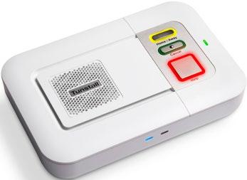
2 Your Tunstall Smart Hub The Tunstall Smart Hub is connected to the mains power supply and has a builtin battery in case of mains power failure. The Smart Hub connects to a cellular network, via a SIM card, enabling you to generate an immediate call for help when and if you need it. This will connect you to the Customer Care Centre, via the Smart Hub s powerful loudspeaker and microphone, where trained care consultants will provide you with the assistance you require. In the background the Smart Hub regularly sends it status via heart beats to the Device Management Platform (DMP). The DMP will allow trained care consultants to remotely configure the Smart Hub based on your individual needs. The rear of your Smart Hub Ethernet Port (Yellow) Micro USB Port (service use only) Tunstall TAPIT port (service use only) Home/Away Button (Yellow) Speaker Cancel Button (Green) Socket for the Power Supply Unit Connector for external GSM antenna (optional extra) Cellular Signal Strength LED Status LED (Red/Green) Microphone Ethernet Connectivity LED Help Button (Red) Radio Antenna page 2 of 24 page 3 of 24
 up to 1m.")
3 Your pendant Your pendant is wirelessly connected to your Smart Hub and enables you to generate a call for help from anywhere in your home or garden. The pendant should be worn at all times and can be worn around the neck or on the wrist using the attachments supplied. The pendant is water resistant (to IP67 standard) up to 1m. It can be worn in the shower however wearing it in the bath should be avoided where possible. How to self-install your Tunstall Smart Hub alarm Before you can start using your Tunstall Smart Hub alarm, please complete the following steps: Step 1. Situating your alarm The unit should be safely located in an area providing good audio coverage for the user. It should not be close to sources of heat, noise or electrical interference. The unit should be located within two metres of an easily accessible mains power socket and in a place which ensures the unit receives a stable 3G cellular signal e.g. near a window. The pendant has the below features: Water resistant * The pendant will automatically send a notification call via the Smart Hub to the Customer Care Centre when its battery is low. LED indication on the pendant Internal radio range = 50m (typical) External line of sight radio range = 200m+ When pressed, the red LED on the pendant will light up to indicate activation. The green LED will light up when the Smart Hub base unit has received the signal from the pendant. If the red LED flashes when pressed, this indicates that the pendant battery is low and should be replaced. LED Auto Low Battery* Step 2. Connecting to mains power Plug the mains adaptor into the socket on the back of the Smart Hub labelled DC and then connect the adaptor to the mains power. Once the Smart Hub has been powered up, it will attempt to connect to the Tunstall DMP using a cellular data connection. During this time the status LEDs on the top and front of the Smart Hub will indicate progress. Wait until the alarm announces Cellular data connection restored which should take less than two minutes. Note: Only use with the power adaptor supplied with the home unit (part number XD ). Tunstall recommends connecting the mains adaptor to a dedicated power point and not to connect it to a double adaptor or power board. Step 3. Testing signal strength The Smart Hub can provide continuous signal strength announcements. The cellular network level is announced as a spoken value from 00 (no signal) to 31 (strong signal). page 4 of 24 page 5 of 24
4 To check signal strength, press and hold the yellow Home / Away button for seven seconds. The Smart Hub will continue to announce signal strength for a period of five minutes and can be stopped by pressing the green Cancel button. Tunstall recommends a minimum level of eight to ensure the Smart Hub can successfully and consistently connect to the Telstra 3G network. If required, additional antennas are available to order via your Tunstall supplier. The colour of the cellular signal strength LED light also indicates the strength of the signal received. Cellular signal strength LED colour Indicative signal strength Antenna requirements Green 19+ (Strong) Not applicable Yellow 7 to 18 (Good) External antenna Red 1 to 6 (Poor) High gain external antenna White No SIM or network connection High gain external antenna (may not resolve coverage) Flashing white Incorrect SIM PIN Not applicable Antenna installation (optional) Antenna requirements Once the Smart Hub has been connected to mains power, you can begin testing the signal strength. During testing of the signal strength, if the alarm has announced a signal strength of eight or less, or if the cellular signal strength LED light is yellow, red or white, you may need to attach an external antenna to improve signal coverage from the Smart Hub. External vs High Gain External antenna An external antenna is a short antenna designed to be used inside the home to boost the Smart Hub s ability to receive a 3G signal. A high gain external antenna is designed for outdoor use where a stronger signal boost is required. Attaching an external antenna To connect the antenna to the Smart Hub alarm unit, simply screw the antenna lead to the antenna port on the back of the alarm (indicated below), ensuring that the lead is screwed in firmly: NOTE: If the cellular signal strength is good, registering between 7 and 18, the use of an external antenna maybe required to increase the signal strength. If so, attach and activate the antenna using the instruction s outlined on page seven and eight. Antenna port If the cellular signal strength is poor, registering between 1 and 6, a high gain external antenna maybe required to increase the signal strength. Please contact Tunstall s Customer Service Centre on for further information. page 6 of 24 page 7 of 24
5 The correct positioning of the antenna is very important in low signal areas. To maximise the signal, it is best to position both the alarm and antenna in an open area with clear line of sight outside e.g. near a window. NOTE: Make sure the antenna cable is unravelled fully and do not remove the adhesive backing until enhanced signal strength has been confirmed from the desired location. Activating an external antenna Once the antenna has been attached to the Smart Hub, the antenna can be activated by pressing and holding down the yellow Home / Away button until the alarm announces External antenna selected to indicate that it has switched from internal to external antenna configuration. To revert to the internal antenna, simply press and hold the yellow Home / Away button until the alarm announces Internal antenna selected. NOTE: If the Smart Hub has weak or no cellular signal strength, the external antenna will need to be attached and activated in an area of adequate cellular signal strength, then returned to the installation point. If you find, after following the instructions above, that the alarm signal strength is still below recommended levels, you may require a high gain external antenna, and should contact Tunstall s Customer Service Centre on for further information. Step 4. Testing the pendant range Your Smart Hub comes with a pre-programmed pendant. If you have purchased an additional pendant or sensor, advise the Tunstall care consultant of this when you test your Smart Hub and it will be remotely programmed for you. To test the pendant range, press and hold the green Cancel button until the unit beeps (approximately five seconds). The unit will announce Programming Mode and the red Help button will flash slowly. Test the pendant by activating it from key areas within the home and around the perimeter of the property. You should expect a range of more than 50 metres inside the home, depending on the environment. The Smart Hub pendant is bi-directional which means the LED will flash red while it is transmitting to the base unit and change to green when the base unit responds. The base unit will also announces the trigger type after each successful pendant press. To exit Pendant Test Mode, press the green Cancel button. IMPORTANT: Please ensure the alarm has sufficient 3G signal strength (8+) and you have completed the pendant range test before moving on to Step 5. If the signal strength is below eight, please complete the antenna installation on page seven of this guide. page 8 of 24 page 9 of 24


6 Step 5. Test the alarm unit Call the Tunstall Customer Care Centre on and advise the care consultant that you have installed your Smart Hub alarm. They will ask you for information including: Client details Smart Hub serial number Smart Hub product code SIM mobile number Internal or external antenna Any additional pendants or sensors Sensor Gateway installation (if applicable) Once the care consultant has entered these details, they will advise you to press the pendant to raise a test call. You have now completed the installation of the Smart Hub. Using the Tunstall Smart Hub Making an alarm call Press the button on the pendant or the red Help button on the Smart Hub. The Smart Hub will announce the trigger activated, and after approximately 5 seconds also announce Press cancel button to cancel the alarm. If the activation was accidental, you can cancel the alarm call at this point. (see below Cancelling an alarm call). If you do not cancel the alarm, the Smart Hub will then announce Do not worry, contacting assistance. The call will be answered by a care consultant at the Customer Care Centre. Tell them why you have generated the alarm call and they will arrange for assistance. Cancelling an alarm call After the help button is pressed, after approximately 5 seconds the alarm will announce Press cancel button to cancel the alarm. Once the green Cancel button has been pressed, the Smart Hub will announce The alarm call has been cancelled. This in-built delay prevents accidental cancellation of an alarm. False alarms If you accidentally generate an alarm, please do not worry as the care consultants are always happy to hear from you and the raising of the alarm acts as a useful test of your Smart Hub. page 10 of 24 page 11 of 24
 On Off Status LED (green/red) Green LED on Red LED flashing (1 every 4 seconds) Red LED flashing (1 every second) Red/green flashing Yellow LED flashing Help button (red")

7 Warning/status lights on the Tunstall Smart Hub How to respond to announcements The Smart Hub has warning and status lights to clearly indicate its status based on the below. Home/away button (yellow LED) On Off Status LED (green/red) Green LED on Red LED flashing (1 every 4 seconds) Red LED flashing (1 every second) Red/green flashing Yellow LED flashing Help button (red LED) On Flashing (1 every 4 seconds) Flashing (1 every second) Green Yellow Red White Flashing white Green Orange Off Smart Hub status Away mode Home mode Smart Hub status Normal mode Low internal battery No external communications Reduction in radio range Configuration/software update in progress Smart Hub status Normal mode Normal mode running on battery Alarm in progress Cellular signal strength status LED Strong signal Good signal Poor signal No SIM or network connection Incorrect SIM PIN Ethernet connection status LED Connected to the router and has internet access Connected to the router and has no internet access Not connected to the router Announcement Red button Pendant Activation Press Cancel button to cancel the alarm The alarm call has been cancelled Do not worry contacting assistance Please wait while we connect you to an operator Please wait... Connected to Monitoring Centre Alarm call completed The alarm call sequence has ended Incoming call. Press pendant or Cancel button to cancel the alarm What to do An alarm has been initiated using the red Help button. An alarm has been initiated using a radio pendant. Normal message heard during an alarm. If the cancel button is pressed then the alarm in progress will be cancelled. Normal message heard as a result of using the cancel button to cancel an alarm before connection to a monitoring centre is attempted. Normal message indicating that an alarm call connection to the monitoring centre has been initiated (the alarm can no longer be cancelled). Normal message to provide continued reassurance that an alarm is being progressed. This will be repeated until a connection with the monitoring centre is achieved. Normal message. The call is being presented to operators and awaiting selection. Expect an operator to speak shortly afterwards. Normal message. Heard when protocol and monitoring centre use a call back method for speech operation. Expect an operator to speak shortly afterwards. Normal message heard when the alarm has been cleared by the monitoring centre operator. An alarm has occurred and the Smart Hub has tried to contact a Control Centre but not been successful. Press the cancel button to acknowledge and stop the message repeating. Contact the Service Provider and check that the Smart Hub s call sequences and destinations are correctly programmed. Normal message. This is heard when the mobile phone number of the alarm unit is receiving a call (ringing). page 12 of 24 page 13 of 24
8 Announcement What to do Announcement What to do There is no mains power The mains power is OK Away Home Programming Mode Registration Mode Please wait, measuring signal strength Signal strength is...<1 to 31> External antenna selected Internal antenna selected Remove the power cable Applying new device settings New device settings applied Heard if power is disconnected. Check the Smart Hub is plugged into a working electrical socket. It is normal to hear this message after power has been reconnected to the Smart Hub. No action required. Yellow button has been pressed and unit is now in Away mode. Normal operational message. Yellow button has been pressed and unit is now in Home mode. Normal operational message. Green button has been used to enter programming mode. During programming mode the range of radio devices can be tested without raising alarms. Green button has been used to enter registration mode and allowing new radio devices to be registered. May be heard after yellow button has been held depressed for 6 seconds and Smart Hub is measuring strength of cellular signal prior to announcing. Heard after yellow button has been held depressed for 6 seconds and Smart Hub is indicating strength of cellular network signal. Heard after yellow button has been held depressed for 10 seconds and Smart Hub has switched antenna connection from internal to external. NB this mode should only be used when an external antenna is fitted. Heard after yellow button has been held depressed for 10 seconds and Smart Hub has switched antenna connection from external to internal. Heard after the green button has been held depressed for 10 seconds signifying opportunity to shut-down the unit (if power cable is removed promptly) ready for transportation. Changed settings have been prepared for the Smart Hub through the DMP. These have been downloaded and are being updated. No action required. Updated settings have been applied and are in use. No action required. Connected to DMP Connection attempt to DMP failed Software download started/pauses/resumed/ completed/failed Software installation started/completed/failed Battery low Reduction in radio range detected Cellular data connection failure The Smart Hub has been able to connect to the DMP. This should be heard if a short press of the cancel button is made whilst no alarm is pending. No action required. The Smart Hub is unable to connect to the DMP. This indicates that no IP communication method is available and/or it cannot reach DMP. Check that internet communications are available through the router/cellular service and that the DMP service is active. The Smart Hub is in the process of obtaining updated software. No action required. If the download fails it should be rescheduled and in the meantime operation will continue with the original software. The status will be known to the Service Provider through the DMP. The Smart Hub is in the process of installing new software it has already downloaded. No action required. If installation fails operation will continue with the original software and a further attempt scheduled. The status will be known to the Service Provider through the DMP. Please note that the Smart Hub will reboot after a software/firmware update This message may be heard when a Smart Hub is first powered up if it has been in storage for a long period, or after a long mains power failure. Check the Smart Hub is plugged into a working electrical socket and allow time for the battery to charge. This may happen in the presence of strong radio interference impeding the ability to receive from radio peripheral devices. Check that the Smart Hub is not close to any other electrical devices such as a computer, television, fan, mobile phone. If so, turn-off or move the equipment away from the Smart Hub and check if this stops the warning. Contact the supplier if this does not resolve the issue. The unit is unable to connect to a cellular data service. If the cellular network is known to be operational or the situation persists then contact your supplier. page 14 of 24 page 15 of 24
9 Announcement Cellular data connection restored Ethernet connection failure Ethernet connection restored SIM card removed SIM card PIN error SIM card locked No mobile network coverage What to do Cellular coverage has reconnected. No action required. The unit is no longer connected to the router. Check the Ethernet cable and router. The Ethernet connection is restored and can now communicate with the router. No action required. The SIM card has been removed from the Smart Hub. Re-insert SIM card. The SIM card has a security protection for which the Smart Hub has not been configured. Ensure that the correct card is being used and settings are correct. The SIM card is locked preventing use after too many attempts to use with an incorrect security PIN. Contact the Smart Hub and SIM supplier. A SIM card is fitted but the Smart Hub is not able to connect to a cellular network. Check the SIM is valid and the internal/external antenna selection is correct. Try using and re-positioning an external antenna. Check if a suitable network signal should be available using another device or information provided by the network or your supplier. The Smart Hub should not be relied upon in this condition. Adding or removing pendants and sensors While your Smart Hub comes with a pre-programmed pendant, if you have purchased an additional pendant or a telecare sensor, please contact the Customer Care Centre by pressing the red Help button on your Smart Hub and advise the care consultant who will remotely program this to your alarm for you. If you have lost or no longer use the pendant or sensor, the Smart Hub will alert the Customer Care Centre that the sensor is missing. To stop these alerts the sensor needs to be removed from your Smart Hub. Please contact the Customer Care Centre by pressing the red Help button on your Smart Hub and advise the care consultant will action this for you remotely. If the warning messages persist or in case of other announcements please contact your supplier. page 16 of 24 page 17 of 24
10 How to self-install your Tunstall Sensor Gateway (if applicable) The Sensor Gateway provides a means of using Tunstall legacy sensors operating on the 312MHz frequency with the new Tunstall Smart Hub alarm, which operates on the 915MHz frequency. The sensor gateway will receive the transmissions from the 312MHz legacy sensors and re-transmit them at 915MHz. The Sensor Gateway is powered by the Smart Hub and will remain powered even if the mains power fails, for as long as the Smart Hub internal battery has sufficient charge. Fitting the Sensor Gateway Programming legacy sensors to the alarm Legacy sensors with plug and play functionality can be programmed to the Smart Hub by calling the Customer Care Centre. After advising the care consultant that you have installed a Sensor Gateway, they will program the legacy sensors to your Smart Hub remotely. Range test The Smart Hub has a range test feature that enables you to test the range of personal triggers without raising an alarm call. This is done by putting the Smart Hub into Programming Mode. When in Programming Mode, press the required personal trigger; if it is within range the home unit will beep and announce the sensor type. 1. Remove the four black rubber feet from the rear of the Smart Hub and store them in the slots inside the Sensor Gateway. 2. Plug the Smart Hub mains adaptor into the Smart Hub socket labelled DC. Plug the twisted red and black cable into the socket labelled with a capital T. Then connect the adaptor to the mains power. 3. Tuck the mains power cord behind the alarm and line up the Sensor Gateway so the power cord sits in the gap, ensuring the cord is flat to the back of the alarm unit. 4. Attach the Sensor Gateway to the Smart Hub. First fit the bottom two pegs into the holes where the rubber feet were fitted. Then engage the clips at the top into the slots in the rear of the Smart Hub. Extend the antenna out from the rear of the unit, point towards the ground. This will help to maximise the radio reception range of the Sensor Gateway. page 18 of 24 page 19 of 24
11 Shutdown procedure As the Smart Hub contains mobile phone technology and may announce warning messages, it is essential to fully power down the unit when uninstalled and prior to transportation. Because the unit has an internal back-up battery, simply removing the mains power is not sufficient. Before returning or transporting the Smart Hub alarm, please complete the following steps. Shutdown procedure 1. Press and hold the green Cancel button. You will hear the Smart Hub beep once. Do not release the button but continue holding until the Smart Hub announces Remove the power cable (approximately 10 seconds). 2. Release the green Cancel button and quickly remove the power cable from the rear of the Smart Hub. All the LEDs on the Smart Hub will flash together and then go out to indicate the Smart Hub has now powered down. NOTE: The power must be disconnected as soon as prompted to do so otherwise the shutdown will not occur and the Smart Hub will continue to operate normally on battery power. To re-attempt the shutdown, ensure that the mains power is reconnected and then repeat from Step 1. Help and advice Do s Wear your pendant at all times. Test your Smart Hub on a monthly basis with the Customer Care Centre. Keep the Smart Hub connected to the mains power at all times. Dust the Smart Hub and pendant with a soft cloth which can be slightly moistened with a gentle detergent if required. Don ts Expose the Smart Hub to water or other liquids. Connect cables other than those supplied with the Smart Hub. Move the Smart Hub from the location that it was originally installed. Move objects close to the Smart Hub that are made of metal or create lots of noise or heat, such as televisions, radios, washing machines, microwave ovens, Wi-Fi routers, mobile phones, laptops etc. Attempt to change the battery in the pendant or Smart Hub. Should this become necessary it will be can be carried out by your supplier. Please note: If you are relocating the Smart Hub out of one property into a new one, or within another area of your property, you must ensure the system is plugged in at the new location and a successful test alarm call to the Customer Care Centre is made to ensure it is working properly. page 20 of 24 page 21 of 24
12 Battery Information All batteries should be disposed of in accordance with the latest legislation. CAUTION: Do not ingest battery, chemical burn hazard. The pendant with this product contains a coin/button cell battery. If the coin/ button cell battery is swallowed, it can cause severe internal burns in just 2 hours and can lead to death. Keep new and used batteries away from children. If the battery compartment is not closed securely, stop using the product and notify your supplier. If you think batteries might have been swallowed or placed inside any part of the body, seek immediate medical attention. Technical Details Weight: 680g (1kg packaged) Dimensions: 185mm x 122mm x 41mm (WxLxD) Mains power: 120V - 240V ac Stand-by battery: 2000mAhr capacity (continually internally charged) Back-up time: 40 hours of stand-by operation (minimum expected at date of purchase and when fully charged) Radio frequency: 917.6MHz & 927.8MHz (dual channel) External connections: DC power adapter with 3m cable Quad-band GSM 3G antenna (internal or optional external) Ethernet port IPv4 USB port (installer use only) Environmental Temperature: Humidity: Standards Operating temperature (to perform to full specification) = 0 C to 50 C, storage = -10 C to 55 C Operating relative humidity (non-condensing to perform to full specification) = 0 to 90%, storage relative humidity (non-condensing) = 0 to 93% EMC: AS/NZS CISPR 32:2013, AS/NZS :1994 Safety: AS/NZS :2011 Radio: AS/NZS 4268: A1:2013 PERS: AS4607:1999 MEPS: AS/NZS Pendant: IP67 Design manufacture: ISO9001:2008 RoHS compliant: 2011/65/EU Pendant battery: Cellular: 3V Lithium CR2450 with up to 5 year life The battery can be replaced by your supplier. RISK OF EXPLOSION IF BATTERY IS REPLACED BY AN INCORRECT TYPE. DISPOSE OF USED BATTERIES ACCORDING TO THE INSTRUCTIONS GSM/GPRS/Edge/UMTS page 22 of 24 page 23 of 24
13 Contact Details Australia Tunstall Australasia Pty Ltd ABN Locked Bag Kingsford Smith Drive Eagle Farm Q 4009 AUSTRALIA Telephone: Fax: Sales enquiries: sales@tunstallhealthcare.com.au Support enquiries: info@tunstallhealthcare.com.au New Zealand Tunstall New Zealand Ltd Business No PO Box Tauranga 3110 NEW ZEALAND Telephone: Fax: Sales enquiries: sales@tunstall.co.nz Support enquiries: info@tunstall.co.nz Our policy of continual development means that product specifications and appearance may change without notice. Tunstall does not accept any responsibility for any errors and omissions contained within this document Tunstall Group Ltd. Tunstall and Smart Hub TM are trademarks 8234-UG-20
Tunstall Vi+ User Guide
 Tunstall Vi+ User Guide Your Tunstall Vi home unit The Tunstall Vi home unit is connected to the mains power supply and your telephone line. It enables you to generate a call for help when and if you need
Your Lifeline Vi+ home unit. Your MyAmie pendant
 User Guide Your Lifeline Vi+ home unit The Lifeline Vi+ home unit is connected to the mains power supply and your telephone line. It enables you to generate a call for help when you need it by immediately
Installation and user guide
 Installation and user guide D5307023A www.tunstallap.com Contents What s in the box? 3 The Connect+ 4 Front view 4 Back view 4 End view 4 Installation advice 5 Quick start guide 6/9 Intruder monitoring
Life Changing, Life Saving. The Vibby. User and Installation Guide
 Life Changing, Life Saving The Vibby User and Installation Guide Contents Introduction Getting started Alarm modes Types of falls Simulating a fall Automatic alarm cancellation Manual alarm cancellation
Smart Hub. Connecting people, connected care. What is it? Who is it for? How does it work?
 Smart Hub Connecting people, connected care What is it? The Lifeline Smart Hub is a complete Connected Care monitoring and alarm system for the home. It uses future proof, smart technology to connect service
D C. Caresse GSM Installation and Programming Guide
 D5107148C Caresse GSM Installation and Programming Guide Contents What s in the box?... 3 The home unit... 4 Front view... 4 Back view... 4 End view... 4 What is the Caresse GSM?... 5 How to install the
MEDICAL ALERT SETUP GUIDE
 MEDICAL ALERT SETUP GUIDE GETTING STARTED STARTED You have made a great decision to protect yourself with Medical Alert! Be sure to wear your wrist button or neck button everyday to stay protected all
Lifeline Vi Clever, not complicated
 Solution Sheet Clever, not complicated The is Tunstall s sixth generation home unit and sets the benchmark in the development of telecare solutions. It s the most technically advanced, flexible and simple
Telemetry Communications Device. Installation Guide. Interface for the Emizon managed network. Issue 1: February 2008
 TCD Telemetry Communications Device Installation Guide Interface for the Emizon managed network Issue 1: February 2008 This guide sets out a simple check list together with a step-by-step guide to the
English. Doro CareIP Mobile. User Guide
 English Doro CareIP Mobile User Guide 1. Read first: Safety information Always read and follow the safety information accompanied by this symbol. User s should pay particular attention to the potential
Vibby. Installation Guide. t: f: e: w: uk.tunstall.com Version: V3.9
 Vibby Installation Guide t: 01977 661234 f: 01977 660562 e: enquiries@tunstall.com w: uk.tunstall.com Version: V3.9 Contents 1. Introduction... 3 Exiting from storage mode...4 2. Getting Started... 5 Entering
For Android devices MYQ-G0301 MYQ-G0301C MYQ-G0301D MYQ-G0301LA
 Smart Smart Garage Garage Hub Hub Manual Manual For Android devices MYQ-G0301 MYQ-G0301C MYQ-G0301D MYQ-G0301LA by Before You Start To reduce the risk of SEVERE INJURY to persons: DO NOT enable the MyQ
MK9 series CarePhone. Installers Mauual
 MK9 series CarePhone Installers Mauual 1 Please ensure that the last thing you do before leaving a User with an alarm is to make a test call through to the Monitoring Centre and speak to the Operator.
Lifeline 400 user guide q6 18/2/04 10:56 am Page 2. Lifeline 400. installation and user guide. Part Number D B
 Lifeline 400 user guide q6 18/2/04 10:56 am Page 2 Lifeline 400 installation and user guide Part Number D3707103B Lifeline 400 user guide q6 18/2/04 10:56 am Page 3 Contents Your Lifeline 400 P3-4 What
TYDOM 315. * _Rev.2* GSM domotics transmitter. 1. Presentation
 TYDOM 5 GSM domotics transmitter ) Présentation. Presentation Delta Dore hereby declares that the equipment complies with the essential requirements and other relevant provisions of the R&TTE Directive
IRIS Touch Quick Installation & Maintenance Guide. Version 1.0
 IRIS Touch Quick Installation & Maintenance Guide Version 1.0 Page 2 of 16 IRIS Touch Quick Installation & Maintenance Guide Version 1.0 Contents 1. Introduction... 4 2. Product Features... 4 3. Package
For ios devices MYQ-G0301 MYQ-G0301C MYQ-G0301-D MYQ-G0301LA
 Smart Smart Garage Garage Hub Hub Manual Manual For ios devices MYQ-G0301 MYQ-G0301C MYQ-G0301-D MYQ-G0301LA by Before You Start To reduce the risk of SEVERE INJURY to persons: DO NOT enable the MyQ Smart
MXD3G User Manual Revision 0 July 29, 2013
 MXD3G User Manual Revision 0 July 29, 2013 Manufactured by Mytrex, Inc. 10321 South Beckstead Lane South Jordan, UT 84095 (801) 571-4121, Fax (801) 571-4606 Toll Free (800) 688-9576, Fax (877) 571-4606
A1UL PERS. Personal Emergency Response System. For Technical Support Please Contact Your Service Provider Or Distributor
 A1UL PERS Personal Emergency Response System TABLE OF CONTENTS 1. READ THIS FIRST... 1 2. SYSTEM OVERVIEW.. 1 3. COMPONENTS 2 4. UNIT OPERATION! Standby Mode.. 3! Emergency Activation. 3! Answering Incoming
Quick set-up guide. [Simple plug and play system]
![Quick set-up guide. [Simple plug and play system]](/thumbs/74/70692342.jpg "Quick set-up guide. [Simple plug and play system]") Quick set-up guide [Simple plug and play system] Life is a journey Welcome to your Lifeline at Home service, providing constant reassurance that help is at hand 24 hours a day. Once installed simply press
Quick set-up guide [Simple plug and play system] Life is a journey Welcome to your Lifeline at Home service, providing constant reassurance that help is at hand 24 hours a day. Once installed simply press
communicall connect solutions sheet What is Communicall Connect? Who is it for? What does it consist of?
 solutions sheet communicall connect What is Communicall Connect? Communicall Connect is Tunstall s most advanced grouped housing communication system. Its innovative design builds upon the success of Tunstall
Rev C May GE Interlogix. Part No: R. CareGard. User Guide
 g 466-1936 Rev C May 2003 GE Interlogix www.ge-interlogix.com Part No: 60-883-95R CareGard User Guide FCC Notices FCC Part 15 Information to the User Changes or modifications not expressly approved by
Q3200 Smart Home Alarm. Kit Content and Installation Guide
 Q3200 Smart Home Alarm Kit Content and Installation Guide Table of Contents 1. Introduction 1 2. Installation 4 3. Troubleshooting & Factory Reset 7 4. Specifications 9 Information and illustrations are
The following equipment is included in your Tunstall Home box t :
 Quick set-up guide Life is a journey Welcome to your Tunstall Home service, providing constant reassurance that help is at hand 24 hours a day. Once installed simply press the red button on the Lifeline
TABLE OF CONTENTS. Your Northwood Intouch Unit (Diagram)...1. How to use your Emergency Response System... 2
...1. How to use your Emergency Response System... 2") TABLE OF CONTENTS Your Northwood Intouch Unit (Diagram)...1 How to use your Emergency Response System... 2 Important Information about your Personal Help Button... 3 Answering an Incoming Call Handsfree...4
TABLE OF CONTENTS Your Northwood Intouch Unit (Diagram)...1 How to use your Emergency Response System... 2 Important Information about your Personal Help Button... 3 Answering an Incoming Call Handsfree...4
Q3000 Smart Home Alarm. Kit Content and Installation Guide
 Q3000 Smart Home Alarm Kit Content and Installation Guide Table of Contents 1. Introduction 1 2. Installation 4 3. Troubleshooting & Factory Reset 7 4. Specifications 9 Information and illustrations are
3G Personal Alert System Self Installation Guide
 3G Personal Alert System Self Installation Guide RAA recommends that you ask a second person to help you with installation. Please follow all instructions in this guide. If you have any questions please
NON-MONITORED EMERGENCY CALL SYSTEMS
 NON-MONITORED EMERGENCY CALL SYSTEMS A non-monitored emergency call system includes a pendant and a control box or phone which is connected to the telephone network (via landline or mobile network). When
National Broadband Network. User Guide. Includes important information about your NBN equipment
 National Broadband Network User Guide Includes important information about your NBN equipment 1 CONTENTS Quick start guide 4 Connecting the Network Termination Device to your own equipment 5 Maintaining
IRIS Touch Quick Installation & Maintenance Guide. Version 1.0
 IRIS Touch Quick Installation & Maintenance Guide Version 1.0 Contents 1. Introduction... 3 2. Product Features... 3 3. Package Contents... 4 4. Board Configuration... 4 5. Before You Start... 5 6. Installing
Preface. Thank you for purchasing our GSM Security Alarm System ( The System )! The System will keep your home and property safe around the clock.
! The System will keep your home and property safe around the clock.") Preface Thank you for purchasing our GSM Security Alarm System ( The System )! The System will keep your home and property safe around the clock. The GSM Security Alarm ( The Alarm ) adopts the most advanced
Preface Thank you for purchasing our GSM Security Alarm System ( The System )! The System will keep your home and property safe around the clock. The GSM Security Alarm ( The Alarm ) adopts the most advanced
Pella Insynctive Product Guide
 Pella Insynctive Product Guide Sensor Details and Setup for Compatible Home Automation Systems Bridge Integrated Entry Door Sensor Integrated Patio Door Sensor Integrated Window Sensor Universal Window
TYNETEC. Telecare for independent living THE GLOBAL SPECIALIST IN ELECTRICAL AND DIGITAL BUILDING INFRASTRUCTURES MOBILE NETWORK
 Telecare for independent living 3G MOBILE NETWORK THE GLOBAL SPECIALIST IN ELECTRICAL AND DIGITAL BUILDING INFRASTRUCTURES Enabling people to live independently for longer in their own home The Reach Plus
Remote switching machines with a SMS text from your mobile phone! Remote Monitoring your assets in the worldwide by your mobile Phone!
 Remote switching machines with a SMS text from your mobile phone! Remote Monitoring your assets in the worldwide by your mobile Phone! GSM SMS Controller DCS-130 User Manual Ver 1.20 Date Issued: 14-9-2010
User manual. Epi-Care mobile. Danish Care Technology ApS Energivej 3, DK-4180 Sorø version 1.15 Phone: Page 1 of 17
 User manual Epi-Care mobile Phone: +45 58 50 05 65 Page 1 of 17 Introduction The purpose of the Epi-Care mobile epilepsy alarm is to ensure severe seizures are not overseen. Epi-Care mobile recognizes
WIRELESS ALARM SYSTEM WITH TELEPHONE AUTO DIALER
 BAT.LOW AC WIRELESS ALARM SYSTEM WITH TELEPHONE AUTO DIALER THE SYSTEM THAT CALLS YOU! Our WIRELESS ALARM SYSTEM WITH TELEPHONE AUTO DIALER is designed to allow you to create your own security system.
SC-F3G User Manual 1.0
 SC-F3G User Manual 1.0 Table of Contents 1. Introduction... 3 2. Functions... 3 3. Features... 3 4. Package Contents... 3 5. Device Configuration... 4 6. Status LED signals... 5 7. Before You Start...
DualCom GradeShift UDL QUICK GUIDE & INSTRUCTION MANUAL
 DualCom GradeShift UDL QUICK GUIDE & INSTRUCTION MANUAL The most trusted brand in Alarm Signalling www.csldual.com @CSLDualCom CSL DualCom Limited Figure 1 - GradeShift UDL SIM card slot Service LED Aerial
Centaur TM II Cube Slave Alarm Signalling Equipment INSTALLATION GUIDE
 Centaur TM II Cube Slave Alarm Signalling Equipment INSTALLATION GUIDE General Description This guide provides a summary for installing and configuring the Centaur TM Cube Slave Alarm Signalling Equipment
Wireless Alarm system s manual
 MOUNTVIEW TECH AUSTRALIA PTY LTD Wireless Alarm system s manual ADS ECO GSM320 Series ADS Security 1/11/2011 1. Before You Begin For your safety and the safety of others, and to ensure that you get the
T4000 Security Communicator
 Inner Range T4000 Security Communicator 1 T4000 Security Communicator by Inner Range P/N: 998530 / 998530NZ 998530LT (Lite Version) Installation & Operation Manual. Rev: 1.5 Inner Range Pty. Ltd. www.innerrange.com
With Magictrl, you can control MatiGard anytime & anywhere via your smartphone, even without data network.
 MatiGard User Guide 02 Menu Feature-------------------------------------------------------------- 05 Overviews---------------------------------------------------------- 07 Read Before Using-----------------------------------------------
1. Introduction. 2. Product overview
 1. Introduction The AG400011 GSM Alarm panel is a control panel that is compatible with other H-net security devices from Everspring, such as wireless sensors, remote keyfobs, tags, and keypad. With this
Ion Gateway Cellular Gateway and Wireless Sensors
 Page 1 of 9 Account & Network Setup If this is your first time using the Ion Gateway online system site you will need to create a new account. If you have already created an account you can skip to the
DigiAir QUICK GUIDE & INSTRUCTION MANUAL
 DigiAir QUICK GUIDE & INSTRUCTION MANUAL The most trusted brand in Alarm Signalling www.csldual.com @CSLDualCom CSL DualCom Limited Figure 1 - DigiAir Yellow Comms LED Red Fault LED Yellow Service LED
Elderly Care Alarm System
 Introduction 24/7 Peace of mind for your family The GSM Elderly Care Alarm System is a new released smart solution for take care of senior, aged, elder or disabled people on their daily life. Big LED display
Tunstall Vi+ Installation and Programming Guide
 Tunstall Vi+ Installation and Programming Guide 1 Contents Installation Guide... 4 What s in the box?... 4 The Home Console Unit... 5 Installation Advice... 6 Quick start guide... 7 How to install... 7
MEDI-MINDER USER MANUAL
 MEDI-MINDER USER MANUAL TABLE OF CONTENTS TABLE OF CONTENTS...1 INTRODUCTION...1 MEDI-MINDER FEATURES...2 PENDANTS & DETECTORS... 3 USING MEDI-MINDER... 3 DISPLAYS AND WARNINGS...5 CELLULAR SIGNAL QUALITY...
User Guide. Sky Muster service. Includes information about your nbn supplied equipment
 User Guide Sky Muster service Includes information about your nbn supplied equipment Please refer to this guide and the important safety warnings on the back cover before attempting to perform maintenance
SA 2650 Kit User Manual
 SA 2650 Kit User Manual Table of Contents 1. System Installation Planning 1 2. Device Introduction 3 3. Getting Started 6 4. System Default Setting 10 5. Connect2Home Application 11 6. System Information
Memcom Emergency Telephone
 Memcom Emergency Telephone Installation Guide Ref No. 450 900 (GB) Version 2 + + Simple wiring for quick installation + + Integrated LCD display shows you what you have programmed + + All code based programming
Cold chain monitoring technologies. Facility monitoring
 Cold chain monitoring technologies Facility monitoring Advanced wireless data logging system - Cobalt For various controlled environment facilities, equipments and transport conditions, real time monitoring
UNLOCK AMAZING IN YOUR HOME
 telstra.com/unlockamazing visit a telstra store 1800 834 273 CONNECTING YOUR TELSTRA SERVICES ON THE NBN UNLOCK AMAZING IN YOUR HOME C022 OCT13 GET READY FOR YOUR NBN EXPERIENCE Thanks for choosing Telstra
To activate using remote control: press [ ] key once. To activate using keyboard: on panel keyboard [ ] keys once.
![To activate using remote control: press [ ] key once. To activate using keyboard: on panel keyboard [ ] keys once.](/thumbs/93/113878877.jpg "To activate using remote control: press [ ] key once. To activate using keyboard: on panel keyboard [ ] keys once.") Table of Content 1.1General Description----------------------------------------------------------------------2 2.2System Setup-----------------------------------------------------------------------------3
Table of Content 1.1General Description----------------------------------------------------------------------2 2.2System Setup-----------------------------------------------------------------------------3
IRIS Touch Quick Installation & Maintenance Guide. Version 1.6
 IRIS Touch Quick Installation & Maintenance Guide Version 1.6 Page 2 of 16 IRIS Touch Quick Installation & Maintenance Guide Version 1.6 Contents 1. Introduction...4 2. Product Features...4 3. Package
Universal Sensor. Installation Guide. t: f: e: w: uk.tunstall.com Version: V2.97 (421V0R1.
 Universal Sensor Installation Guide t: 01977 661234 f: 01977 660562 e: enquiries@tunstall.com w: uk.tunstall.com Version: V2.97 (421V0R1.18) Contents 1. Features and Introduction... 3 Your Universal Sensor...3
169MHz Telecare Devices Touch Personal Pendant
 169MHz Telecare Devices Touch Personal Pendant What is the Touch Pendant used for? Compatible with Reach at home alarms, Advent xt warden call, Altec Response and Touchsafe Pro Nursecall systems Fully
Programming the Vi+ using a Series Telephone. Tunstall Vi+
 Tunstall Vi+ Programming the Vi+ using a SeriesTelephone Your Vi+ Page 2 Ver 1 4/24/2015 Programming a telecare sensor to the Vi+ Telecare sensors with plug and play functionality can be programmed to
D3D Wi-Fi GSM Smart Alarm System -User Manual
 D3D Wi-Fi GSM Smart Alarm System -User Manual D3D Wi-Fi / GSM Smart Alarm system (Model : D10). Please read all instructions carefully & follow steps for easy home installation. 1 P a g e D3D Wi-Fi / GSM
IRIS Touch Quick Installation & Maintenance Guide. Version 1.0
 IRIS Touch Quick Installation & Maintenance Guide Version 1.0 Page 2 of 16 IRIS Touch Quick Installation & Maintenance Guide Version 1.0 Contents 1. Introduction...4 2. Product Features...4 3. Package
MEDI-LINK USER MANUAL
 MEDI-LINK USER MNUL Medi-Link User Manual Rev1.2 division of NESS CORPORTION PTY LTD November 2015 Unit 4/56 Norcal Rd, Nunawading VIC 3131 ustralia Tel: +61 3 9875 6400 Facsimile: +61 3 9875 6422 Email:
IRIS Connect Series Quick Installation & Maintenance Guide. Version 1.1
 IRIS Connect Series Quick Installation & Maintenance Guide Version 1.1 Contents 1. Introduction... 4 2. Product Features... 4 3. Package Contents... 5 4. Board Configuration... 5 5. Before You Start...
Medi-Minder Guardian USER MANUAL
 Medi-Minder Guardian USER MANUAL 1 Table of Contents TABLE OF CONTENTS...2 INTRODUCTION...2 MEDI-MINDER GUARDIAN...3 PENDANTS AND DETECTORS...4 USING MEDI-MINDER GUARDIAN... 4 DISPLAYS AND WARNINGS...6
COMMUNICATOR ET08 / ET081
 COMMUNICATOR ET08 / ET081 User Manual v1.2 Safety instructions Please read and follow these safety guidelines in order to maintain safety of operators and people around: GSM communicator ET08 / ET081 (further
Contents. Glossary
 Contents Glossary ------------------------------------------------------------------------------------------------------ 6 1. Introduction to the IDS 1632 -------------------------------------------------------------
Touchpad Exit Controller Administration Guide
 Touchpad Exit Controller Administration Guide 2018 RF Technologies, Inc. All specifications subject to change without notice. All Rights Reserved. No Part of this work may be reproduced or copied in any
PORTAL USER MANUAL. Mobeye WaterGuard-FS. Float sensor CM2300FS. SW version 5.n
 SW version 5.n PORTAL USER MANUAL Mobeye WaterGuard-FS Float sensor CM2300FS Attention! Very important This user manual contains important guidelines for the installation and usage of the Mobeye device
600 Range Dialer Installation Manual. Version 1.0
 600 Range Dialer Installation Manual Version 1.0 The information contained is supplied without liability for any errors or omissions. No part may be reproduced or used except as authorised by contract
Ontech GSM 9040/50. Reference Manual English -1 -
 Ontech GSM 9040/50 Reference Manual English -1 - Content Welcome... 5 This manual... 5 Text styles... 5 Support... 5 Disclaimer... 5 Overview... 6 Accessories... 6 External temperature sensor 9901... 7
Personal Assistance System Owner s Manual
 Personal Assistance System Owner s anual 3 3 O UNT A C K G HOUS RCORD nstall Run AC Power Battery Low 4 2 8 3 6 PROG 0 RCORD Personal Assistance System PA800 RAD THS FRST This equipment generates and uses
System. For a better understanding of this product, please read this user manual thoroughly before using it.
 GSM Alarm System User s Manual For a better understanding of this product, please read this user manual thoroughly before using it. Chapter 1. Features Chapter 2. Control Panel Introduction Chapter 3.
PERMACONN PM1030 Includes DI300. Installation Manual
 PERMACONN PM1030 Includes DI300 Installation Manual Radio Data Comms Unit 5/20-30 Stubbs Street Silverwater NSW 2128 Telephone: 02 9352 1777 Facsimile: 02 9352 1700 Introduction The PERMACONN system provides
Mobeye CM2410 GSM fire alarm communicator
 PORTAL USER MANUAL Mobeye CM2410 GSM fire alarm communicator Accessory for Ei Electronics fire detector SW version 5.n Incl. CM2400 Attention! Very important This user manual contains important guidelines
INDEPENDANT LIVING SOLUTIONS
 INDEPENDANT LIVING SOLUTIONS AS40607 Medical Alarm with advanced care functionality Who we are What we do Jupl is a technology services provider focused on the global Eldercare and Independent Living markets.
GSM RFID VOICE Alarm System
 GSM RFID VOICE Alarm System User s Manual For a better understanding of this product, please read this user manual thoroughly before using it. CONTENTS [Function Instruction] [Control Panel] Control Panel
Supervised Security System Owner's Guide
 Owner's Guide PSC06 READ THIS FIRST This equipment generates and uses radio frequency energy, and if not installed and used properly, that is, in strict accordance with the manufacturers instructions,
Careline Anna Careline GSM
 Careline Anna / Careline GSM Programming and installation manual List of contents 1 Introduction... 3 1.1 General description of Careline Anna/GSM... 3 1.2 General description of Tx4 alarm transmitter...
IFT-RC150 IntelliFire Touch Remote Control Installation Instructions
 IFT-RC150 IntelliFire Touch Remote Control Installation Instructions Leave this manual with party responsible for use and operation. 1. Introduction The IFT-RC150 is a wall mounted device that is designed
Any additional devices linked to the system ET08 (computer, sensors, relays etc.) must be approved by LST EN standard.
 must be approved by LST EN standard.") COMMUNICATOR ET08 User Manual v1.0 Safety instructions Please read and follow these safety guidelines in order to maintain safety of operators and people around: GSM communicator (gateway) ET08 (further
COMMUNICATOR ET08 User Manual v1.0 Safety instructions Please read and follow these safety guidelines in order to maintain safety of operators and people around: GSM communicator (gateway) ET08 (further
SmartLINK Module Ei3000MRF for Mains Powered Multi-Sensor Fire / Smoke / Heat / CO Alarms - Ei3000 Series
 SmartLINK Module Ei3000MRF for Mains Powered Multi-Sensor Fire / Smoke / Heat / CO Alarms - Ei3000 Series Instruction Manual Read and retain carefully for as long as the product is being used. It contains
DeLaval activity meter system Instruction Book
 Instruction Book 87224201 2014-02-17, Version 4 Original instruction Table of contents EC Declaration of Conformity -... 5 Safety precautions... 7 DeLaval activity meter AM2 DeLaval activity receiver
Smart Starter Bundle. Hub. Smart Motion Sensor. Smart Door/ Window Sensor
 User Guide 01 Smart IP Camera Smart Zigbee Hub Smart Motion Sensor Smart Door/ Window Sensor Smart Starter Bundle Thanks for using Aztech Kyla product If you need support or help, please visit www.kyla.aztech.com
GRADESHIFT UDL INSTRUCTION MANUAL 2.5 APPENDIX
 GRADESHIFT UDL INSTRUCTION MANUAL 2.5 APPENDIX GradeShift UDL Instruction Manual 2.5 Appendix 2.5 APPENDIX SPECIFICATIONS Dimensions 21 mm (h), 132mm (w), 94mm (d) Weight 140g including NVM and SIM Temperature
GSM Alarm System. User s Manual. Profile. MOBILE CALL GSM Alarm System
 MOBILE CALL GSM Alarm System GSM Alarm System System disarmed 11/26/2013 User s Manual Profile For a better understanding of this product, please read this user manual thoroughly before using it. CONTENTS
User Guide. Fibre Connection. For installations after July 1st 2013 Includes information about your NBN equipment
 User Guide Fibre Connection For installations after July 1st 2013 Includes information about your NBN equipment Please refer to this guide, and to the important safety warnings on the back cover before
The Windcrest Remote Alarm for Passenger and Goods Lifts with Optional BS EN81-28 & BS EN81-70
 The Windcrest Remote Alarm for Passenger and Goods Lifts with Optional BS EN81-28 & BS EN81-70 1. Identify the Equipment and carry out a Risk Assessment before installation AD1000EN- 1R Main Unit EN1 Speaker
Lone Worker Duress Security Hazard Zone Remote Area Health Care DURESS & SAFETY TECHNOLOGIES I N T E R N A T I O N A L
 Lone Worker Duress Security Hazard Zone Remote Area Health Care DURESS & SAFETY TECHNOLOGIES www.duressandsafety.com.au Creating safer environments for people Increasingly organisations recognise the need
USER & INSTALLATION GUIDE
 Reach Plus At Home Alarm Unit Touch Personal Pendant USER & INSTALLATION GUIDE www.tynetec.co.uk SECTION 1 USER INSTRUCTIONS Section Topic Page 1.1 Important Information 3 1.2 Unpacking the Reach Plus
MEDI-MINDER USER MANUAL
 MEDI-MINDER USER MANUAL TABLE OF CONTENTS TABLE OF CONTENTS... 1 INTRODUCTION... 1 SMARTLINK FEATURES... 2 USING SMARTLINK... 3 SPECIAL FUNCTIONS... 5 DISPLAYS AND WARNINGS... 6 SPECIFICATIONS... 7 INTRODUCTION
D B Version 9.9. Lifeline Vi/Vi+ Installation and Programming Guide
 D5307013B Version 9.9 Lifeline Vi/Vi+ Installation and Programming Guide Contents Installation Guide... 4 What s in the box... 4 Your home unit... 5 For your safety - Installation advice... 6 Quick start
MOBILE CALL GSM Alarm System User s Manual
 MOBILE CALL GSM Alarm System User s Manual Profile For a better understanding of this product, please read this user manual thoroughly before using it. Contents Function Introduction (3) Alarm Host Diagram
Register the Gateway via PC. Package Content. Gateway Installation. 1 x Gateway 1 x Voice Siren 1 x IP Camera*
 Package Content 1 x Gateway 1 x Voice Siren 1 x IP Camera* Register the Gateway via PC Create a new account at www.elro-smartalarm.com 1. Click on Create a new account 1 x PIR Motion 1 x Magnetic 1 x Remote
NEO IP/GSM Technical Handbook
 NEO IP/GSM Technical Handbook NE41 09002-02 v2.0 Copyright 2011 Neat Electronics AB Revision date: 2011-12-19 NEAT Electronics AB Varuvägen 2 SE-246 42 Löddeköpinge Sweden Phone: +46 46 70 70 65 Fax: +46
Voice Board. Installation and Programming Guide. Runner 4/8,PowerWave 4/8/16 &, Elite64. Add-on Board For Storing Recorded Voice Messages
 ELECTRONIC ENGINEERING LTD. Voice Board Runner 4/8,PowerWave 4/8/16 &, Elite64 Add-on Board For Storing Recorded Voice Messages And listen-in. Installation and Programming Guide. P/N 7101372 Rev. C V.K
Vcare. User Manual. Ver WiFi - GSM- App. Smart Home Security System
 Vcare User Manual Ver.20161126 WiFi - GSM- App Smart Home Security System Tips:. Carefully read through this user manual prior to installation. Keep the user manual in a safe place for future reference
ThinkPro Security and Automation Panel User Guide
 ThinkPro Security and Automation Panel User Guide North America s Fastest Growing Alarm Company 1-855-768-4465 (1-855-76-THINK) V.1.1 Welcome to Think Protection Thank you for choosing a Think Protection
ElkGuard. Owner's Manual. Self-Contained Wireless Security System. ElkGuard
 ElkGuard TM Self-Contained Wireless Security System ElkGuard Owner's Manual THIS MANUAL IS PROVIDED TO ACQUAINT YOU WITH THE OPERATION OF THE SYSTEM AND HELP YOU BECOME PROFICIENT WITH IT S OPERATION.
Preparing. for the nbn network. Hybrid Fibre Coaxial (HFC)
") Preparing for the nbn network Hybrid Fibre Coaxial (HFC) 2 Preparing for the nbn network Thanks for switching to the nbn network You re only days away from enjoying Australia s exciting new landline phone
Preparing for the nbn network Hybrid Fibre Coaxial (HFC) 2 Preparing for the nbn network Thanks for switching to the nbn network You re only days away from enjoying Australia s exciting new landline phone
The future of security, secured IP by security professionals, for the professional security industry
 The future of security, secured IP by security professionals, for the professional security industry Installation and Service Engineer Support Telephone: +44 871 977 1133 (Calls are charged at 10p a minute
Preparing. Your connection checklist. for the nbn Fixed Wireless network. For help and support. Installation approval
 Your connection checklist Installation approval am approved for installation at my heritage-listed premises (if applicable). Connection date My service provider has informed me of my connection date and