COMMUNICATOR ET08 / ET081
|
|
|
- Abraham Maxwell
- 5 years ago
- Views:
Transcription


1 COMMUNICATOR ET08 / ET081
2 User Manual v1.2 Safety instructions Please read and follow these safety guidelines in order to maintain safety of operators and people around: GSM communicator ET08 / ET081 (further referenced as system or device) contains a radio transceiver operating in GSM850/900/1800/1900 bands. DO NOT use the system where it can interfere with other devices and cause any potential danger. DO NOT use the system with medical devices if this is required in the manual of the medical device. DO NOT use the system in hazardous environment. DO NOT expose the system to high humidity, chemical environment or mechanical impacts. DO NOT attempt to personally repair the system. System labelling sticker is at the bottom of the device. System ET08 / ET081 is a device mounted in limited access areas. Any system repairs must be done only by qualified, safety aware personnel. Mains power must be disconnected before any installation or tuning work starts. The system installation or maintenance must not be done during stormy conditions. 300mA power supply which must be approved by LST EN stan- The system must be powered by main 10-24V dard and be easily accessible. Any additional devices linked to the system ET08 / ET081 (computer, sensors, relays etc.) must be approved by LST EN standard. External power supply can be connected to AC mains only inside installation room with automatic 2-pole circuit breaker capable of disconnecting circuit in the event of short circuit or over-current condition. Open circuit breaker must have a gap between connections of more than 3mm and the disconnection current is 5A. Phase Null PE USB cable ET08/ ET081 AC 230V 50 Hz/DC 24V Fuse F1 model - minismdc 500mA. Blown fuse cannot be replaced by the user and the replacement fuses have to be exactly the same as indicated by the manufacturer. The device is fully turned off by disconnecting 2-pole switch off device of the external power supply or any other linked device that the system ET08 / ET081 is powered from. The WEEE (Waste Electrical and Electronic Equipment) marking on this product (see left) or its documentation indicates that in the EU the product must not be disposed of together with household waste. Copyright ELDES UAB, All rights reserved. It is strictly forbidden to copy and distribute information in this document or pass to a third party without an advanced written authorization from ELDES UAB. ELDES UAB reserves the right to update or modify this document and/or related products without a warning. Hereby, ELDES UAB declares that this communicator ET08 / ET081 is in compliance with the essential requirements and other relevant provisions of Directive 1999/5/EC. The declaration of conformity may be consulted at
3 Limited Liability The buyer must agree that the system will reduce the risk of fire, theft, burglary or other dangers but does not guarantee against such events. EL- DES UAB will not take any responsibility regarding personal, property or revenue loss while using the system. ELDES UAB responsibility according to local laws does not exceed value of the purchased system. ELDES UAB is not affiliated with GSM operators providing cellular services, therefore is not responsible for network services, coverage or its operation. Manufacturer Warranty The system carries a 24-month warranty by the manufacturer ELDES UAB. Warranty period starts from the day the system has been purchased by the end user. The warranty is valid only if the system has been used as intended, following all guidelines listed in the manual and within specified operating conditions. Receipt with purchase date must be kept as a proof. The warranty is voided if the system has been exposed to mechanical impacts, chemicals, high humidity, fluids, corrosive and hazardous environment or other force majeure factors. Package Content 1. System ET08 / ET pcs 2. ET08 / ET081 user manual...1 pcs 3. GSM antenna...1 pcs 4. Jumpers...4 pcs. 5. Fastening holders...4 pcs. About User Manual This document describes communicator ET08 / ET081, its operation and installation. It is very important to read User Manual before start using the system. CONTENTS 1. General Information Operation Description Technical Specifications Electrical & Mechanical Specifications Main Unit, Connector, Pin & LED Functionality Main Unit Functionality Connector Functionality Pin Functionality LED Functionality Connection Circuit Installation Communication Modes Communication Mode 1. Data Transmission from Alarm System to Monitoring Station via GSM Audio Channel Communication Mode 2. Data Transmission from Alarm System to Preset User (-s) by SMS Communication Mode 3. Data Transmission from Alarm System to Monitoring Station via GSM Audio Channel and SMS Messages to Preset User (-s) Communication Mode 4. Data Transmission from Alarm System to Monitoring Station via GPRS Network Communication Mode 5. Data Transmission from Alarm System to Monitoring Station via PSTN using GSM Audio Channel as Backup Connection Communication Mode 6. Data Transmission from Alarm System to Monitoring Station via PSTN using SMS Messages as Backup Connection Communication Mode 7. Data Transmission from Alarm System to Monitoring Station via PSTN using GSM Audio Channel as Backup Connection and SMS Messages to Preset User (-s) Communication Mode 8. Data Transmission from Alarm System to Monitoring Station via PSTN using GPRS Network as Backup Connection Communication Mode 9. Data Transmission from Alarm System to Monitoring Station via PSTN through PBX using GSM Audio Channel as Backup Connection Communication Mode 10. Data Transmission from Alarm System to Monitoring Station via PSTN through PBX using SMS Messages as Backup Connection Communication Mode 11. Data Transmission from Alarm System to Monitoring Station via PSTN through PBX using GSM Audio Channel as a Backup Connection and SMS Messages to Preset User (-s) Communication Mode 12. Data Transmission from Alarm System to Monitoring Station via PSTN through PBX using GPRS Network as Backup Connection SMS Commands* Appendix Restoring Default Parameters Upgrading Firmware ELDES Configuration Tool Software Technical Support... 25
4 1. General Information Communicator ET08 / ET081 is a device for transmitting data from alarm system to monitoring station via: GSM audio channel; GSM audio channel and/or to users via SMS message; Telehone landline (PSTN); GPRS network. The system can be used in the following applications: Property security. GSM network backup for PSTN. 1.1 Operation Description ET08 / ET081 communicator acts as a gateway between the alarm system and monitoring station providing a dial tone and fully replacing the landline (PSTN). The communicator notifies monitoring station (ET081 ONLY) and/or the preset user by SMS message in case PSTN is unavailable, has been cut off or disconnected by PSTN provider. ET08 / ET081 supports only outgoing calls. DTMF number dialing mode in alarm system must be enabled. ET08 / ET081 can detect temporary service suspension by the service provider for technical or billing reasons even if a dial tone is still present (optional feature). ET08 / ET081 features several communication ways between alarm system and monitoring station via: 1. GSM audio channel; 2. PSTN using GSM audio channel as backup connection; 3. SMS messages to preset users; 4. PSTN using GSM audio channel as backup connection with data duplication to preset users via SMS; 5. GPRS network. 6. PSTN using GPRS network as backup connection. Please, refer to chapter 4. Communication Modes for more details. The system ET08 / ET081 has 1 digital input (normally open) for sensor connection. The open collector output allows to connect and control 1 electronic appliance on receipt of the correct SMS text message from one of the preset phone numbers. This feature provides control over heating, lighting, gates, blinds etc. ELDES Configuration Tool software is used to configure the system to operate in one of its communication modes, providing data transmission either via SMS text message or via GPRS. The device has to be connected to the computer using a USB cable. Please, refer to software s HELP section for more details. 4
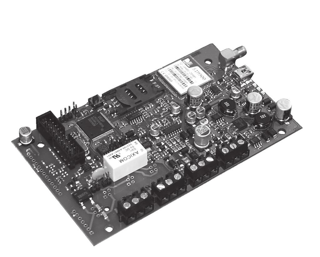
5 2. Technical Specifications 2.1 Electrical & Mechanical Specifications Power Supply 10-24V 300mA max Current Used in Standby Mode GSM Modem Frequency 120mA max 850/900/1800/1900 MHz Supported Protocols Contact ID, 4+2** Maximum Number of Users to whom SMS Messages are Delivered Number of Low Level (Negative) Digital Inputs* 1 Allowable Input Values* Input Type Number of Outputs* 1 Output Circuit* Maximum Allowed Output Values* Dimensions Operating temperature range Generated Phone Line Voltage Generated Phone Line Current Generated Phone Line Impedance Dial Tone Frequency of Generated Phone line 5 Voltage: V; current: mA NO (normally open) Open collector output. Output is pulled to COM when turned on. Voltage: 30V ; current: 50 ma 130 x 73 mm o C 18 V 25 ma 600 Ω 350 Hz * only in ET081 ** 4+2 protocol operates in communication mode 1, 5 and 9 ONLY (via GSM audio channel). 2.2 Main Unit, Connector, Pin & LED Functionality For configurations DEFAULT SIM CARD GSM MODEM ANT SET MODE PROG USB B1 B2 INFO STATUS GSM F1 L1 L2 L3 L4 RING TIP C1 DC+ COM N/A N/A Z1 Fig. No 1 USER MANUAL ELDES ET08 / ET081 V1.2 5
6 2.2.1 Main Unit Functionality GSM MODEM SIM CARD ANT F1 USB GSM network 850/900/1800/1900 MHz modem SIM card slot / holder GSM antenna SMA type connector Fuse model minismdc 500mA Mini USB port Connector Functionality Labelling L1 - L4 RING TIP C1 DC+ COM Z1 N/A Description Landline or PBX contacts (according to backup mode) RING contact TIP contact Output Positive power supply contact Negative power supply contact / Common contact Input Not available Pin Functionality Labelling Description DEFAULT For restoring factory default settings SET For enabling communication modes MODE For enabling communication modes B1, B2 For communication backup connection PROG Not used LED Functionality Labelling INFO STATUS GSM Description Working mode indicator Device activity indicator GSM network quality indicator GSM Signal Strength Indication GSM signal strength is indicated by GSM LED. To ensure the best quality of the network adjust the position of GSM antenna and find the strongest possible signal by observing the GSM LED indications. GSM LED Indication Off Flashing every 3 seconds Flashing every 1 second Flashing several times per second On GSM Signal Strength No connection The connection is not reliable Satisfactory Good Excellent It is recommended to install the GSM antenna away from the alarm system to ensure better quality of the audio signal. It is not recommend to install the antenna inside the metal enclosure. 6
7 There are also a few other indicators - device activity indicator STATUS and working mode indicator INFO. Device Activity Indication STATUS LED Indication Off Flashing several times per second On Meaning No power supply or some fault is present SIM card is not inserted / insterted improperly Device is operating and ready for use Working Mode Indication INFO LED Indication Off Flashing several times per second On Meaning Device is in standby mode Device retransmits the data sent from alarm system to the monitoring station (this indication is possible when device is operating in communication mode 1) Device is decoding Contact ID data to user-understandable text format. 2.3 Connection Circuit COM connectors of ET08 / ET081 and alarm system unit must be connected. ET081 Input Z1 is connected to PGM output of alarm system unit if PGM output is implemented as open collector circuit or any other circuit and if it commutes with COM. It is also possible to connect motion sensor or any other sensor to ET081 Z1 input. ET081 C1 output can be connected to input of electronic appliance and if it commute with COM. This connection allows to control heating, lighting, gates, blinds, water pump etc. ET08 / ET081 Z1 * DC+ COM C1 * PGM Fig. No 2 * - only in ET V Alarm system or other appliance USER MANUAL ELDES ET08 / ET081 V1.2 7
8 3. Installation NOTE: Due to GSM network characteristics it is recommended that ET08/ET081 be equipped with a SIM card from the same GSM operator who provided the SIM cards used by users who will receive messages from the system. Thus you will ensure the quickest SMS message delivery and receipt. NOTE: To ensure maximum system operation reliability we recommend not to use pay-as-you-go SIM cards. If the balance is insufficient the system will not be able to inform users by SMS or send Contact ID messages. IMPORTANT: Power supply at alarm system must be disconnected before any installation or tuning work. The system can be installed in a metal or non-flammable plastic enclosure together with alarm control panel. When the metal enclosure is also used it is necessary to ground the enclosure using yellow/green colour cable. For the connection use 0.50 mm 2 1 thread cable. Device Installation and Pre-operation: 1. Fasten the system in the enclosure using fastening holders. 2. Place SIM card into the SIM card slot and fix it with holder after making sure that SIM card PIN code is disabled. PIN code can be disabled by inserting the SIM card into mobile phone and following proper menus. SIM card should not have any remaining SMS messages. 3. Connect the GSM antenna to SMA connector. It is not recommended to turn on the device without GSM antenna connected. 4. Connect the circuit according to desired communication mode (see chapter 4. Communication Modes) 5. The system should start in less than a minute. GSM LED indicator should be blinking or be ON indicating successful connection to GSM network. 8
9 4. Communication Modes ATTENTION: DTMF phone number dialing mode must be enabled on alarm system, activated Contact ID or 4+2 data transmission protocol and monitoring station phone number set with international code, i.e. For UK London 20xxxxxxxx or xxxxxxxx. The <plus> character is not allowed. 4.1 Communication Mode 1. Data Transmission from Alarm System to Monitoring Station via GSM Audio Channel In this mode the communicator retransmits Contact ID or 4+2 data sent from alarm system to monitoring station via GSM audio channel. There is NO backup connection for this mode. NOTE: No additional communicator configuration is required for this mode. L1 L2 L3 L4 RING TIP C1 DC+ COM N/A N/A Z1 RING/TIP AUX+ AUX- ALARM SYSTEM Fig. No 3 1. Connect the circuit as indicated in Fig. No. 3 connect telephone contacts of the alarm system RING/TIP to RING/TIP contacts of the communicator. 2. Connect power supply to DC+/COM contacts. Power supply is usually used as AUX- and AUX+ output of alarm system. 3. No jumpers have to be set on any pins. See Fig. No. 4 for correct jumper position. Fig. No 4 USER MANUAL ELDES ET08 / ET081 V1.2 9
10 4.2 Communication Mode 2. Data Transmission from Alarm System to Preset User (-s) by SMS. In this mode the communicator retransmits Contact ID data sent from alarm system and decodes it to user-understandable text format which is sent to preset user (-s) by SMS message. There is NO backup connection for this mode. NOTE: User phone number (-s) must be set for the communicator using ELDES Configuration Tool. Please, refer to software's HELP section for more details. ATTENTION: It is also necessary to set monitoring station phone number on alarm system in this mode. In such case you can use any number (one digit is enough). L1 L2 L3 L4 RING TIP C1 DC+ COM N/A N/A Z1 RING/TIP AUX+ AUX- ALARM SYSTEM Fig. No 5 1. Connect the circuit as indicated in Fig. No. 5 connect telephone contacts of the alarm system RING/TIP to RING/TIP contacts of the communicator. 2. Connect power supply to DC+/COM contacts. Power supply is usually used as AUX- and AUX+ output of alarm system. 3. Set the jumper on MODE pins. See Fig. No. 6 for correct jumper position. Fig. No 6 10
11 4.3 Communication Mode 3. Data Transmission from Alarm System to Monitoring Station via GSM Audio Channel and SMS Messages to Preset User (-s) In this mode the communicator retransmits Contact ID data sent from alarm system to monitoring station via GSM audio channel. In addition, the data is duplicated and decoded data to user-understandable text format and sent to preset user (-s) by SMS message. There is NO backup connection for this mode. NOTE: User phone number (-s) must be set for the communicator using ELDES Configuration Tool. Please, refer to software's HELP section for more details. L1 L2 L3 L4 RING TIP C1 DC+ COM N/A N/A Z1 RING/TIP AUX+ AUX- ALARM SYSTEM Fig. No 7 1. Connect the circuit as indicated in Fig. No. 7 connect telephone contacts of the alarm system RING/TIP to RING/TIP contacts of the communicator. 2. Connect power supply to DC+/COM contacts. Power supply is usually used as AUX- and AUX+ output of alarm system. 3. Set the jumper on SET pins. See Fig. No. 8 for correct jumper position. Fig. No 8 USER MANUAL ELDES ET08 / ET081 V1.2 11
12 4.4 Communication Mode 4. Data Transmission from Alarm System to Monitoring Station via GPRS Network NOTE: EGR100 software is required for this communication mode. The software is freeware and can be downloaded from ELDES website at In this mode the communicator retransmits Contact ID data via GPRS network sent from alarm system to monitoring station. There is NO backup connection for this mode. I. The following communicator GPRS settings must be set up using ELDES Configuration Tool software: CID over GPRS Enabled enables Contact ID data transmission via GPRS network. APN access-point-name provided by GSM operator. User Name user name provided by GSM operator. Password password provided by GSM operator. Server IP external IP address of the computer (router) running EGR100 software. Server Port forwarded UDP port for the computer running EGR100 software. Please, refer to ELDES Configuration Tool software's HELP section for more details. II. The following settings must be set up in EGR100 software: TCP/UDP Server Port - forwarded port for communication with the device via GPRS. Please, refer to EGR100 software's user guide for more details. NOTE: UDP port must be set the same both on the communicator using ELDES Configuration Tool and in EGR100 software. L1 L2 L3 L4 RING TIP C1 DC+ COM N/A N/A Z1 RING/TIP AUX+ AUX- ALARM SYSTEM Fig. No 9 1. Connect the circuit as indicated in Fig. No. 9 connect telephone contacts of the alarm system RING/TIP to RING/TIP contacts of the communicator. 2. Connect power supply to DC+/COM contacts. Power supply is usually used as AUX- and AUX+ output of alarm system. 3. Set the jumpers on SET and MODE pins. See Fig. No. 10 for correct jumper position. Fig. No 10 12
13 4.5 Communication Mode 5. Data Transmission from Alarm System to Monitoring Station via PSTN using GSM Audio Channel as Backup Connection In this mode the communicator retransmits Contact ID and 4+2 data via landline (PSTN) sent from alarm system to monitoring station. The communicator also monitors the voltage (dial tone monitoring optional) on the PSTN and in case the PSTN is unavailable, disconnected or cut off (voltage drops below 4V), the system: switches to backup connection GSM audio channel, notifies monitoring station about PSTN failure, continues transmitting data to monitoring station via GSM audio channel until the PSTN is restored. NOTE: Notification about PSTN loss/restore (if required) has to be enabled for the communicator using ELDES Configuration Tool. Please, refer to software s HELP section for more details. L1 L2 L3 L4 RING TIP C1 DC+ COM N/A N/A Z1 To landline (PSTN) RING/TIP AUX+ AUX- ALARM SYSTEM Fig. No Connect the circuit as indicated in Fig. No. 11 connect telephone contacts of the alarm system RING/TIP to RING/TIP contacts of communicator. 2. Connect L3/L4 contacts to landline (PSTN). 3. Connect power supply to DC+/COM contacts. Power supply is usually used as AUX- and AUX+ output of alarm system. 4. Set the jumpers on B1 and B2 pins. See Fig. No. 12 for correct jumper position. Fig. No 12 USER MANUAL ELDES ET08 / ET081 V1.2 13
14 4.6 Communication Mode 6. Data Transmission from Alarm System to Monitoring Station via PSTN using SMS Messages as Backup Connection In this mode the communicator retransmits Contact ID data via landline (PSTN) sent from alarm system to monitoring station. The communicator also monitors the voltage (dial tone monitoring optional) on the PSTN and in case the PSTN is unavailable, disconnected or cut off (voltage drops below 4V), the system: sends an SMS report to the preset user (-s) on PSTN failure, decodes data to user-understandable text format and continues transmitting it to preset user (-s) by SMS message until the PSTN is restored. NOTE: User phone number (-s) must be set for the communicator using ELDES Configuration Tool. Please, refer to software's HELP section for more details. L1 L2 L3 L4 RING TIP C1 DC+ COM N/A N/A Z1 To landline (PSTN) RING/TIP AUX+ AUX- ALARM SYSTEM Fig. No Connect the circuit as indicated in Fig. No. 13 connect telephone contacts of the alarm system RING/TIP to RING/TIP contacts of communicator. 2. Connect L3/L4 contacts to landline (PSTN). 3 Connect power supply to DC+/COM contacts. Power supply is usually used as AUX- and AUX+ output of alarm system. 4. Set the jumpers on B1, B2 and MODE pins. See Fig. No. 14 for correct jumper position. Fig. No 14 14
15 4.7 Communication Mode 7. Data Transmission from Alarm System to Monitoring Station via PSTN using GSM Audio Channel as Backup Connection and SMS Messages to Preset User (-s) In this mode the communicator retransmits Contact ID data via landline (PSTN) sent from alarm system to monitoring station. The communicator also monitors the voltage (dial tone monitoring optional) on the PSTN and in case the PSTN is unavailable, disconnected or cut off (voltage drops below 4V), the system: switches to backup connection GSM audio channel, notifies monitoring station about PSTN failure, sends an SMS report to the preset user (-s) on PSTN failure, continues transmitting data to monitoring station via GSM audio channel until the PSTN is restored, duplicates and decodes data to user-understandable text format and sends it to preset user (-s) by SMS message until the PSTN is restored. NOTE: User phone number (-s) must be set and notification about PSTN loss/restore (if required) has to be enabled for the communicator using ELDES Configuration Tool. Please, refer to software s HELP section for more details. for more details. L1 L2 L3 L4 RING TIP C1 DC+ COM N/A N/A Z1 To landline (PSTN) RING/TIP AUX+ AUX- ALARM SYSTEM Fig. No Connect the circuit as indicated in Fig. No. 15 connect telephone contacts of the alarm system RING/TIP to RING/TIP contacts of communicator. 2. Connect L3/L4 contacts to landline (PSTN). 3. Connect power supply to DC+/COM contacts. Power supply is usually used as AUX- and AUX+ output of alarm system. 4. Set the jumpers on B1, B2 and SET pins. See Fig. No. 16 for correct jumper position. Fig. No 16 USER MANUAL ELDES ET08 / ET081 V1.2 15
16 4.8 Communication Mode 8. Data Transmission from Alarm System to Monitoring Station via PSTN using GPRS Network as Backup Connection In this mode the communicator retransmits Contact ID data via landline (PSTN) sent from alarm system to monitoring station. The communicator also monitors the voltage (dial tone monitoring optional) on the PSTN and in case the PSTN is unavailable, disconnected or cut off (voltage drops below 4V), the system: switches to backup connection GPRS network, notifies monitoring station about PSTN failure, continues transmitting data to monitoring station via GPRS network until the PSTN is restored. NOTE: Notification about PSTN loss/restore (if required) has to be enabled for the communicator using Please, refer to software s HELP section for more details. I. The following communicator GPRS settings must be set up using ELDES Configuration Tool software: CID over GPRS Enabled enables Contact ID data transmission via GPRS network. APN access-point-name provided by GSM operator. User Name user name provided by GSM operator. Password password provided by GSM operator. Server IP external IP address of the computer (router) running EGR100 software. Server Port forwarded UDP port for the computer running EGR100 software. Please, refer to ELDES Configuration Tool software's HELP section for more details. II. The following settings must be set up in EGR100 software: TCP/UDP Server Port - forwarded port for communication with the device via GPRS. Please, refer to EGR100 software's user guide for more details. NOTE: UDP port must be set the same both on the communicator using ELDES Configuration Tool and in EGR100 software. L1 L2 L3 L4 RING TIP C1 DC+ COM N/A N/A Z1 To landline (PSTN) RING/TIP AUX+ AUX- ALARM SYSTEM Fig. No Connect the circuit as indicated in Fig. No. 17 connect telephone contacts of the alarm system RING/TIP to RING/TIP contacts of communicator. 2. Connect L3/L4 contacts to landline (PSTN). 3. Connect power supply to DC+/COM contacts. Power supply is usually used as AUX- and AUX+ output of alarm system. 4. Set the jumpers on B1, B2, SET and MODE pins. See Fig. No. 18 for correct jumper position. Fig. No 18 16
17 FOR ADVANCED USERS ONLY! 4.9 Communication Mode 9. Data Transmission from Alarm System to Monitoring Station via PSTN through PBX using GSM Audio Channel as Backup Connection In this mode the communicator retransmits alarm system Contact ID or 4+2 data to monitoring station via landline (PSTN) through private branch exchange station (PBX). The communicator also monitors the voltage (dial tone monitoring optional) on the external PSTN. In case the external PSTN is unavailable, disconnected or cut off (voltage drops below 4V), the system: switches to backup connection GSM audio channel, notifies monitoring station about PSTN failure, continues transmitting data to monitoring station via GSM audio channel until the external PSTN is restored. NOTE: Notification about PSTN loss/restore (if required) has to be enabled for the communicator using ELDES Configuration Tool. Please, refer to software s HELP section for more details. To external landline (PSTN) L1 L2 L3 L4 RING TIP C1 DC+ COM N/A N/A Z1 PBX RING TIP AUX+ AUX- Internal landline (PSTN) ALARM SYSTEM Fig. No Connect the circuit as indicated in Fig. No. 19 connect telephone contacts of the alarm system RING/TIP to RING/TIP contacts of communicator. 2. Connect L1/L2 contacts to external landline (PSTN). 3. Connect L3/L4 contacts to internal landline (PSTN) of PBX. 4. Connect power supply to DC+/COM contacts. Power supply is usually used as AUX- and AUX+ output of alarm system. 5. No jumpers have to be set on any pins. See Fig. 20 for correct jumper position. Fig. No 20 USER MANUAL ELDES ET08 / ET081 V1.2 17
18 FOR ADVANCED USERS ONLY! 4.10 Communication Mode 10. Data Transmission from Alarm System to Monitoring Station via PSTN through PBX using SMS Messages as Backup Connection In this mode the communicator retransmits alarm system Contact ID data to monitoring station via landline (PSTN) through private branch exchange station (PBX). The communicator also monitors the voltage (dial tone monitoring optional) on the external PSTN. In case the external PSTN is unavailable, disconnected or cut off (voltage drops below 4V), the system: sends an SMS report to the preset user (-s) on PSTN failure, decodes data to user-understandable text format and continues transmitting it to preset user (-s) by SMS message until the external PSTN is restored. NOTE: User phone number (-s) must be set and notification about PSTN loss/restore (if required) has to be enabled for the communicator using ELDES Configuration Tool. Please, refer to software s HELP section for more details. To external landline (PSTN) L1 L2 L3 L4 RING TIP C1 DC+ COM N/A N/A Z1 PBX RING TIP AUX+ AUX- Internal landline (PSTN) ALARM SYSTEM Fig. No Connect the circuit as indicated in Fig. No. 21 connect telephone contacts of the alarm system RING/TIP to RING/TIP contacts of communicator. 2. Connect L1/L2 contacts to external landline (PSTN). 3. Connect L3/L4 contacts to internal landline (PSTN) of PBX. 4. Connect power supply to DC+/COM contacts. Power supply is usually used as AUX- and AUX+ output of alarm system. 5. Set the jumper on MODE pins. See Fig. No. 22 for correct jumper position. Fig. No 22 18
19 FOR ADVANCED USERS ONLY! 4.11 Communication Mode 11. Data Transmission from Alarm System to Monitoring Station via PSTN through PBX using GSM Audio Channel as Backup Connection and SMS Messages to Preset User (-s) In this mode the communicator retransmits alarm system Contact ID data to monitoring station via landline (PSTN) through private branch exchange station (PBX). The communicator also monitors the voltage (dial tone monitoring optional) on the external PSTN. In case the external PSTN is unavailable, disconnected or cut off (voltage drops below 4V), the system: switches to backup connection GSM audio channel, notifies monitoring station about PSTN failure, sends an SMS report to the preset user (-s) on PSTN failure, continues transmitting data to monitoring station via GSM audio channel until the external PSTN is restored, duplicates and decodes data to user-understandable text format and sends it to preset user (-s) by SMS message until the external PSTN is restored. NOTE: User phone number (-s) must be set and notification about PSTN loss/restore (if required) has to be enabled for the communicator using ELDES Configuration Tool. Please, refer to software s HELP section for more details. To external landline (PSTN) L1 L2 L3 L4 RING TIP C1 DC+ COM N/A N/A Z1 PBX RING TIP AUX+ AUX- Internal landline (PSTN) ALARM SYSTEM Fig. No Connect the circuit as indicated in Fig. No. 23 connect telephone contacts of the alarm system RING/TIP to RING/TIP contacts of communicator. 2. Connect L1/L2 contacts to external landline (PSTN). 3. Connect L3/L4 contacts to internal landline (PSTN) of PBX. 4. Connect power supply to DC+/COM contacts. Power supply is usually used as AUX- and AUX+ output of alarm system. 5. Set the jumper on SET pins. See Fig. No. 24 for correct jumper position. Fig. No 24 USER MANUAL ELDES ET08 / ET081 V1.2 19
20 FOR ADVANCED USERS ONLY! 4.12 Communication Mode 12. Data Transmission from Alarm System to Monitoring Station via PSTN through PBX using GPRS Network as Backup Connection In this mode the communicator retransmits alarm system Contact ID data to monitoring station via landline (PSTN) through private branch exchange station (PBX). The communicator also monitors the voltage (dial tone monitoring optional) on the external PSTN. In case the external PSTN is unavailable, disconnected or cut off (voltage drops below 4V), the system: switches to backup connection GPRS network, notifies monitoring station about PSTN failure, continues transmitting data to monitoring station via GPRS network until the external PSTN is restored. NOTE: Notification about PSTN loss/restore (if required) has to be enabled for the communicator using ELDES Configuration Tool. Please, refer to software s HELP section for more details. I. The following communicator GPRS settings must be set up using ELDES Configuration Tool software: CID over GPRS Enabled enables Contact ID data transmission via GPRS network. APN access-point-name provided by GSM operator. User Name user name provided by GSM operator. Password password provided by GSM operator. Server IP external IP address of the computer running EGR100 software. Server Port forwarded UDP port for the computer running EGR100 software. Please, refer to ELDES Configuration Tool software's HELP section for more details. II. The following settings must be set up in EGR100 software: TCP/UDP Server Port - forwarded port for communication with the device via GPRS. Please, refer to EGR100 software's user guide for more details. NOTE: UDP port must be set the same both on the communicator using ELDES Configuration Tool and in EGR100 software. To external landline (PSTN) L1 L2 L3 L4 RING TIP C1 DC+ COM N/A N/A Z1 PBX RING TIP AUX+ AUX- Internal landline (PSTN) ALARM SYSTEM Fig. No 25 20
21 FOR ADVANCED USERS ONLY! 1. Connect the circuit as indicated in Fig. No. 25 connect telephone contacts of the alarm system RING/TIP to RING/TIP contacts of communicator. 2. Connect L1/L2 contacts to external landline (PSTN). 3. Connect L3/L4 contacts to internal landline (PSTN) of PBX. 4. Connect power supply to DC+/COM contacts. Power supply is usually used as AUX- and AUX+ output of alarm system. 5. Set the jumper on SET and MODE pins. See Fig. No. 26 for correct jumper position. Fig. No 26 USER MANUAL ELDES ET08 / ET081 V1.2 21
22 5. SMS Commands* * - only in ET081 ATTENTION! In this user manual the underscore _ character represents one <space> character. There must be no spaces or other characters at the beginning and at the end of the message. XXXX 4-digit SMS password. In order to configure and control ET081 system using SMS message, send the text command to ET081 SIM card phone number from one of the authorized phone numbers. The structure of SMS message consists of 4-digit SMS password (the default SMS password is 0000 four zeros), the command and the parameters. For some commands the parameters are not applied, i.e. STATUS. ET081 notifies the user if a mistake was made in SMS command: Command is not correct. Status The SMS report indicating information on system input and output status. SMS text: XXXX_STATUS Password The 4-digit SMS password intended for system configuration and control via SMS messages. Manufacturer default SMS password is 0000 (four zeros) which is NECESSARY to change. SMS text: 0000_PSW_XXXX Value: XXXX new 4-digit password. Output ON This function switches the output ON. SMS text: XXXX_ON 22
23 Output OFF This function switches the output OFF. SMS text: XXXX_OFF Output Pulse ON This function switches the output ON for a set period of time and switches the output back to OFF after the set period of time is over. SMS text: XXXX_ON_T Value: T period of time in seconds, range - [1-9999] Output Pulse OFF This function switches the output OFF for a set period of time and switches the output back to ON after the set period of time is over. SMS text: XXXX_OFF_T Value: T period of time in seconds, range - [1-9999] Telephone Line Failure/Restore Delay The delay period of time between telephone line failure and restore events. If telephone line failure and restore events occur before the set delay period of time is over, the system will not send the SMS report. SMS text: XXXX_TELDLY_T Value: T period of time in seconds, range - [1-250] USER MANUAL ELDES ET08 / ET081 V1.2 23
24 6. Appendix 6.1 Restoring Default Parameters To restore the default parameters: 1. Disconnect the power supply; 2. Short circuit (connect) DEFAULT pins; 3. Power up ET08 / ET081 for 7 seconds; 4. Disconnect the power supply; 5. Remove short circuit from DEFAULT pins; 6. Parameters restored to default. 6.2 Upgrading Firmware 1. Disconnect the power supply and backup battery. 2. Short circuit (connect) DEFAULT pins. 3. Connect the device via USB cable to the PC. 4. Power up the device. 5. The new window must pop-up where you will find the.bin file. Otherwise open My Computer and look for Boot Disk drive. 6. Delete the.bin file found in the drive. 7. Copy the new firmware.bin file to the very same window. 8. Power down the device. 9. Unplug USB cable. 10. Remove short circuit from DEFAULT pins. 11. Power up the device. 12. Firmware upgraded. NOTE: It is strongly recommended to restore default parameters after the firmware upgrade. 6.3 ELDES Configuration Tool Software To configure the system, please install configuration software ELDES Configuration Tool which can be downloaded from ELDES website at Before connecting USB cable to the computer, please, read ELDES Configuration Tool user guide available in the HELP section of the software. 24
25 6.4 Technical Support Indication Possible Reason GSM LED is off or not flashing No external power supply Circuit not properly connected Blown fuse No GSM network signal STATUS LED flashing several times per second SIM card not inserted / improperly inserted PIN code enabled SIM card inactive System does not send any SMS messages SIM card credit limit exceeded Incorrect SMS centre phone number No GSM network signal User phone number is not preset. Received SMS message Incorrect Format or Command is not correct Incorrect syntax Extra <space> character is left in SMS message For product warranty repair service, please, contact your local retail store where this product was purchase. If your problem could not be fixed by the self-guide above, please, contact your distributor or ELDES technical support by support@eldes.lt More up to date information about your device and other products can be found at the manufacturer s website USER MANUAL ELDES ET08 / ET081 V1.2 25
26 For notes 26
27 For notes USER MANUAL ELDES ET08 / ET081 V1.2 27
28 Made in Lithuania.
Any additional devices linked to the system ET08 (computer, sensors, relays etc.) must be approved by LST EN standard.
 must be approved by LST EN standard.") COMMUNICATOR ET08 User Manual v1.0 Safety instructions Please read and follow these safety guidelines in order to maintain safety of operators and people around: GSM communicator (gateway) ET08 (further
COMMUNICATOR ET08 User Manual v1.0 Safety instructions Please read and follow these safety guidelines in order to maintain safety of operators and people around: GSM communicator (gateway) ET08 (further
EWR2 WIRELESS SIGNAL REPEATER
 SIGNAL REPEATER User manual v1.0 Compatible with: ESIM364 Ver.02.07.11 and up EPIR3 Ver.01.01.00 and up EWP1 Ver.16 and up EKB3W Ver.8 and up EW1 Ver.33 and up EWS1 Ver.16 and up EWD1 Ver.19 and up EWK1
1. CONTENTS OF PACK 2. TECHNICAL SPECIFICATIONS ... User Manual v1.1. Compatible with: ESIM264 v and up. ESIM364 all versions
 EKB2 LCD KEYPAD User Manual v1.1 Compatible with: ESIM264 v7.09.02 and up. ESIM364 all versions Main features: Alarm system arming & disarming; STAY-arming & disarming; parameter configuration; PGM output
1. Package content. User Manual v1.3
 LED KEYPAD EKB3 User Manual v1.3 Compatible with: ESIM264 v07.14.02 and up. ESIM364 v02.06.01 and up. Main features: Alarm system arming & disarming; Stay mode activation & deactivation; System parameter
ET082 GSM/GPRS COMMUNICATOR
 ET082 GSM/GPRS COMMUNICATOR User Manual v2.2 Valid for ET082 v01.14.00 and up; hardware version: ET082-30 and up. SAFETY INSTRUCTIONS Please read and follow these safety guidelines to safeguard yourself
ET083 2G/3G COMMUNICATOR
 ET083 2G/3G COMMUNICATOR EN User Manual v1.0 Valid for ET083 v01.00.00 and up SAFETY INSTRUCTIONS Please read and follow these safety guidelines to safeguard yourself and others: 2G/3G communicator ET083
SC-F3G User Manual 1.0
 SC-F3G User Manual 1.0 Table of Contents 1. Introduction... 3 2. Functions... 3 3. Features... 3 4. Package Contents... 3 5. Device Configuration... 4 6. Status LED signals... 5 7. Before You Start...
EWS3 WIRELESS INDOOR SIREN
 EWS3 WIRELESS INDOOR SIREN User manual v1.2 Compatible with: ESIM264 v7.14.07 and up. ESIM364 v02.06.09 and up.. ESIM384 all versions. EPIR2 v01.01.12 and up. EPIR3 all versions. PITBULL ALARM all versions.
EP364 USER MANUAL ALARM AND MANAGEMENT SYSTEM
 EP364 USER MANUAL ALARM AND MANAGEMENT SYSTEM User Manual v1.0 Safety instructions Please read and follow these safety guidelines in order to maintain safety of operators and people around: DO NOT use
EKB3W WIRELESS LED KEYPAD
 EKB3W WIRELESS LED KEYPAD User manual v1.6 Compatible with: ESIM364 all versions. EPIR v05.06.02 and up + EWT2 v16.17 and up. EPIR2 all versions. EPIR3 all versions. Main features: Alarm system arming
EWP2WIRELESS MOTION DETECTOR
 EN EWP2WIRELESS MOTION DETECTOR User manual v1.2 Compatible with: ESIM364 v02.08.00 and up. EPIR3 v1.2.0 and up EPIR2 v01.03.02 and up Main features: Built-in dual element passive infrared (PIR) sensor.
IP & SMS Alarm Communicator
 Models: WGSMSC You deserve to feel safe, secure & protected IP & SMS Alarm Communicator Quick Start Guide Thank you for purchasing a Watchguard IP & SMS Alarm Communicator This Quick Start Guide covers
Тел: Моб: Skype: Discoverytelecom Mail: EWK2 EWK2A WIRELESS KEYFOB
 Тел: +7 495 7907870 Моб: +7 965 4429948 Skype: Discoverytelecom Mail: info@discoverytelecom.ru www.discoverytelecom.ru A WIRELESS KEYFOB User Manual v1.1 Compatible with: ESIM264 v7.14.00 and up + EWT1
600 Range Dialer Installation Manual. Version 1.0
 600 Range Dialer Installation Manual Version 1.0 The information contained is supplied without liability for any errors or omissions. No part may be reproduced or used except as authorised by contract
PERMACONN PM1030 Includes DI300. Installation Manual
 PERMACONN PM1030 Includes DI300 Installation Manual Radio Data Comms Unit 5/20-30 Stubbs Street Silverwater NSW 2128 Telephone: 02 9352 1777 Facsimile: 02 9352 1700 Introduction The PERMACONN system provides
GSM ALARM AND MANAGEMENT SYSTEM ESIM264 COMPLIES WITH EN GRADE 2, CLASS II REQUIREMENTS
 GSM ALARM AND MANAGEMENT SYSTEM ESIM264 COMPLIES WITH EN 50131-1 GRADE 2, CLASS II REQUIREMENTS CONTENTS 1. General Information... 8 1.1 Functionality... 8 1.2 Compatible Device Overview... 8 1.3 Default
GLOBAL. InstallatIon & operation manual
 InstallatIon & operation manual INDEX 1. INTRODUCTION... 5 2. FEATURES AND FUNCTIONS 2.1 Reporting Options... 2.2 Interfaces... 2.3 Programming... 2.4 Indicators and Controls...... 6 6 6 6 6 3. INSTALLATION...
IRIS Touch 200 Range Dialler Installation Manual. Version 1.4
 IRIS Touch 200 Range Dialler Installation Manual Version 1.4 The information contained is supplied without liability for any errors or omissions. No part may be reproduced or used except as authorised
Other trade names mentioned in this document may be registered trademarks or trademarks of respective product manufacturers or vendor products.
 Attention! Read this user manual carefully. Representative of the company installing the alarm system will explain which security module SP231 functions needs to be activated to ensure proper security
IRIS Touch Quick Installation & Maintenance Guide. Version 1.0
 IRIS Touch Quick Installation & Maintenance Guide Version 1.0 Page 2 of 16 IRIS Touch Quick Installation & Maintenance Guide Version 1.0 Contents 1. Introduction... 4 2. Product Features... 4 3. Package
IRIS Touch 400 & 600 Range Installation Manual. Honeywell Galaxy Range. Version 2.0
 IRIS Touch 400 & 600 Range Installation Manual Honeywell Galaxy Range Version 2.0 Table of Contents 1 System Overview... 4 2 IRIS Touch 440 & 640 PCB Layout... 5 3 Connection & Configuration for Honeywell
DigiAir QUICK GUIDE & INSTRUCTION MANUAL
 DigiAir QUICK GUIDE & INSTRUCTION MANUAL The most trusted brand in Alarm Signalling www.csldual.com @CSLDualCom CSL DualCom Limited Figure 1 - DigiAir Yellow Comms LED Red Fault LED Yellow Service LED
IRIS Touch Quick Installation & Maintenance Guide. Version 1.0
 IRIS Touch Quick Installation & Maintenance Guide Version 1.0 Page 2 of 16 IRIS Touch Quick Installation & Maintenance Guide Version 1.0 Contents 1. Introduction...4 2. Product Features...4 3. Package
Preface. Thank you for purchasing our GSM Security Alarm System ( The System )! The System will keep your home and property safe around the clock.
! The System will keep your home and property safe around the clock.") Preface Thank you for purchasing our GSM Security Alarm System ( The System )! The System will keep your home and property safe around the clock. The GSM Security Alarm ( The Alarm ) adopts the most advanced
Preface Thank you for purchasing our GSM Security Alarm System ( The System )! The System will keep your home and property safe around the clock. The GSM Security Alarm ( The Alarm ) adopts the most advanced
ABOUT THIS DOCUMENT AND THE DOCUMENT STRUCTURE WE USE
 ABOUT THIS DOCUMENT AND THE DOCUMENT STRUCTURE WE USE isocket Smart Relay is a complex Smart House system which is installed in the fuse cabinet (electric cabinet) in the house. We therefore assume that
IRIS Touch Quick Installation & Maintenance Guide. Version 1.0
 IRIS Touch Quick Installation & Maintenance Guide Version 1.0 Contents 1. Introduction... 3 2. Product Features... 3 3. Package Contents... 4 4. Board Configuration... 4 5. Before You Start... 5 6. Installing
HELPY CONTROLLER QUICK GUIDE
 Alarm system for elevators compliant with the European Standard EN 81-28:2018 HELPY CONTROLLER QUICK GUIDE 05/04/2019 DESCRIPTION Autodialer specifically designed for installation on elevator controller.
V1.0. Smart Home Alarm System. User Manual. APP download via QR Code scanning. Please read the manual carefully before using.
 V1.0 Smart Home Alarm System User Manual APP download via QR Code scanning Please read the manual carefully before using. Content FUNCTION PROFILE 2 THE SCHEMATIC GRAPH OF HOST 3 PROCESS OF BOOTING 6 OPERATION
Manual GPRS Data Logger PCE-GPRS 2
 PCE Americas Inc. 711 Commerce Way Suite 8 Jupiter FL-33458 USA From outside US: +1 Tel: (561) 320-9162 Fax: (561) 320-9176 info@pce-americas.com PCE Instruments UK Ltd. Units 12/13 Southpoint Business
Ontech GSM 9040/50. Reference Manual English -1 -
 Ontech GSM 9040/50 Reference Manual English -1 - Content Welcome... 5 This manual... 5 Text styles... 5 Support... 5 Disclaimer... 5 Overview... 6 Accessories... 6 External temperature sensor 9901... 7
Fitting instructions
 Fitting instructions Ver. 02_English 02. 11. 2017 CONTENT 1 INTRODUCTION... 3 2 FITTING THE PATRIOT EU... 3 2.1 Electronic diagram... 3 2.2 Fitting instructions... 4 2.3 Final placement... 4 2.4 Alarm
Сontrol panel Contact GSM-9N
 Сontrol panel Contact GSM-9N Data sheet Device identification number 2 1. General Information The Contact GSM-9N control panel (hereinafter referred to as the device) is designed for setting up security
Remote switching machines with a SMS text from your mobile phone! Remote Monitoring your assets in the worldwide by your mobile Phone!
 Remote switching machines with a SMS text from your mobile phone! Remote Monitoring your assets in the worldwide by your mobile Phone! GSM SMS Controller DCS-130 User Manual Ver 1.20 Date Issued: 14-9-2010
PORTAL USER MANUAL. Mobeye WaterGuard-FS. Float sensor CM2300FS. SW version 5.n
 SW version 5.n PORTAL USER MANUAL Mobeye WaterGuard-FS Float sensor CM2300FS Attention! Very important This user manual contains important guidelines for the installation and usage of the Mobeye device
English. Doro CareIP Mobile. User Guide
 English Doro CareIP Mobile User Guide 1. Read first: Safety information Always read and follow the safety information accompanied by this symbol. User s should pay particular attention to the potential
To activate using remote control: press [ ] key once. To activate using keyboard: on panel keyboard [ ] keys once.
![To activate using remote control: press [ ] key once. To activate using keyboard: on panel keyboard [ ] keys once.](/thumbs/93/113878877.jpg "To activate using remote control: press [ ] key once. To activate using keyboard: on panel keyboard [ ] keys once.") Table of Content 1.1General Description----------------------------------------------------------------------2 2.2System Setup-----------------------------------------------------------------------------3
Table of Content 1.1General Description----------------------------------------------------------------------2 2.2System Setup-----------------------------------------------------------------------------3
IRIS Touch Firmware Enhancements and Additions from Version to Version
 Overview IRIS Touch Firmware Enhancements and Additions from Version 1.14.3 to Version 1.19.1 This document details enhancements to the feature set of the IRIS Touch from firmware Version 1.14.3 to Version
3G GSM AUTO DIALER. Remote monitoring & Control using your mobile phone. MODEL NUMBER 3GAD1
 3G GSM AUTO DIALER Remote monitoring & Control using your mobile phone www.gsm-activate.co.uk MODEL NUMBER 3GAD1 PAGE 1 Product Information Our 3G GSM Auto Dialer is a versatile unit which can be attached
AZWG10200 ABUS PSTN/IP converter
 AZWG10200 ABUS PSTN/IP converter EN Version 1.0 AZWG10200 Preface Dear Customer, Thank you for purchasing this PSTN/IP converter. This device is built with state-of-the-art technology and complies with
GSM RFID VOICE Alarm System
 GSM RFID VOICE Alarm System User s Manual For a better understanding of this product, please read this user manual thoroughly before using it. CONTENTS [Function Instruction] [Control Panel] Control Panel
IRIS Touch Quick Installation & Maintenance Guide. Version 1.6
 IRIS Touch Quick Installation & Maintenance Guide Version 1.6 Page 2 of 16 IRIS Touch Quick Installation & Maintenance Guide Version 1.6 Contents 1. Introduction...4 2. Product Features...4 3. Package
PRODUCT CATALOGUE. Cape Town 18 Darter Road Blue Water Estate Kommetjie. Gauteng 245 Louis Botha Avenue Orchards Johannesburg
 PRODUCT CATALOGUE Cape Town 18 Darter Road Blue Water Estate Kommetjie Luke Fowles - 076 161 8124 luke@providenttech.co.za Frank Fowles - 082 445 1541 frank@providenttech.co.za www.providenttech.co.za
Instructions manual. By-alarm. By-alarm Manager software
 Instructions manual By-alarm By-alarm Manager software Index 1. Procedure for the complete programming of the By-alarm system 5 Operations to be carried out prior to the programming with By-Alarm Manager
GSM SMS Controller GSM SMS Alarm Unit S130 S140 S150. User Manual
 Remote switching machines with a SMS text from your mobile phone! Remote Monitoring your assets in the worldwide by your mobile Phone! GSM SMS Controller GSM SMS Alarm Unit S130 S140 S150 User Manual Ver
The future of security, secured IP by security professionals, for the professional security industry
 The future of security, secured IP by security professionals, for the professional security industry Installation and Service Engineer Support Telephone: +44 871 977 1133 (Calls are charged at 10p a minute
DualCom GradeShift UDL QUICK GUIDE & INSTRUCTION MANUAL
 DualCom GradeShift UDL QUICK GUIDE & INSTRUCTION MANUAL The most trusted brand in Alarm Signalling www.csldual.com @CSLDualCom CSL DualCom Limited Figure 1 - GradeShift UDL SIM card slot Service LED Aerial
System. For a better understanding of this product, please read this user manual thoroughly before using it.
 GSM Alarm System User s Manual For a better understanding of this product, please read this user manual thoroughly before using it. Chapter 1. Features Chapter 2. Control Panel Introduction Chapter 3.
TYDOM 315. * _Rev.2* GSM domotics transmitter. 1. Presentation
 TYDOM 5 GSM domotics transmitter ) Présentation. Presentation Delta Dore hereby declares that the equipment complies with the essential requirements and other relevant provisions of the R&TTE Directive
A1UL PERS. Personal Emergency Response System. For Technical Support Please Contact Your Service Provider Or Distributor
 A1UL PERS Personal Emergency Response System TABLE OF CONTENTS 1. READ THIS FIRST... 1 2. SYSTEM OVERVIEW.. 1 3. COMPONENTS 2 4. UNIT OPERATION! Standby Mode.. 3! Emergency Activation. 3! Answering Incoming
Monitoring Solutions
 GSM Systems Monitor: Temperature, Humidity, Power, Water, Smoke, Carbon Monoxide and More September 2016 Table of Contents GSM Systems... 3 Argon 100 GSM... 3 Ares 12 & 14 GSM... 4 Poseidon2 4002... 5
1. User features of the GSM dialer
 1. User features of the GSM dialer The JA60GSM dialer offers many useful features described in detail below. The installer should properly demonstrate the use of the system to the user after installation
GSM Alarm System. User s Manual. Profile. MOBILE CALL GSM Alarm System
 MOBILE CALL GSM Alarm System GSM Alarm System System disarmed 11/26/2013 User s Manual Profile For a better understanding of this product, please read this user manual thoroughly before using it. CONTENTS
your silent and loyal servant
 Easy installation, simple programming! your silent and loyal servant The GD-04 is a GSM remote controller-sensor. It sends SMSes, calls - switches on/off and guards. DAViD cannot speak but is understood
HELPY QUICK-TL GSM INTL
 Alarm system for elevators HELPY QUICK-TL GSM INTL QUICK GUIDE 04/02/16 DESCRIPTION A B C D E F G H I L M N O Connector for external LEDs Connector for built-in loudspeaker Built-in loudspeaker Connector
MOBILE CALL GSM Alarm System User s Manual
 MOBILE CALL GSM Alarm System User s Manual Profile For a better understanding of this product, please read this user manual thoroughly before using it. Contents Function Introduction (3) Alarm Host Diagram
Mobeye CM2410 GSM fire alarm communicator
 PORTAL USER MANUAL Mobeye CM2410 GSM fire alarm communicator Accessory for Ei Electronics fire detector SW version 5.n Incl. CM2400 Attention! Very important This user manual contains important guidelines
1. Functions of GPS locator ETLOC-30S 3
 Contents 1. Functions of GPS locator ETLOC-30S 3 1.1 Direct view of the vehicle position on the map 3 1.2 Vehicle security 3 1.2.1 Vehicle protection 3 1.2.1.1 GPS protection 3 1.2.1.2 GPS higher level
USER MANUAL Mobeye ThermoGuard CM2200
 USER MANUAL Mobeye ThermoGuard CM2200 SW version 1.n Attention! Very important This user manual contains important guidelines for the installation and usage of the Mobeye device as described in this manual.
Kwêbeam GSM/Interface/Repeater Module
 1 Kwêbeam GSM/Interface/Repeater Module Features - Full Kwêbeam system control via SMS - Easy to use with no installation required - Built-in backup battery - 868Mhz Kwêbeam repeater functionality - One
GSM 3G AUTO DIALLER. Remote monitoring & Control using your mobile phone. MODEL NUMBER 3GAD1
 GSM 3G AUTO DIALLER Remote monitoring & Control using your mobile phone www.gsm-activate.co.uk MODEL NUMBER 3GAD1 PAGE 1 Product Information Our GSM 3G Auto Dialer is a versatile unit which can be attached
SCAN200E USER S MANUAL
 SCAN200E USER S MANUAL Code No. 2071 1052 rev. 1.4 Code No. 2071 1052 Rev. 1.4 Page 2/16 SCAN200E User s Manual Foreword This manual is for SCAN200E Controller running software version 2.03 or later. We
1. Introduction. 2. Product overview
 1. Introduction The AG400011 GSM Alarm panel is a control panel that is compatible with other H-net security devices from Everspring, such as wireless sensors, remote keyfobs, tags, and keypad. With this
PITBULL ALARM. GSM Alarm System
 PITBULL ALARM GSM Alarm System Contents Technical Specifications...4 Components of the PITBULL ALARM security system...5 1. 7-STEP START GUIDE...6 OVERVIEW...6 2. QUICK START GUIDE...10 2.1. How and where
2G & 3G GSM Portable PIR Alarm
 2G & 3G GSM Portable PIR Alarm www.gsm-activate.co.uk MODEL RF - PORTABLE-PIR PAGE 1 Product Information Our 2G/3G Portable PIR Alarm is a standalone alarm system suitable for indoors or outside usage.
Control panel «Contact GSM-5-2»
 Control panel «Contact GSM-5-2» Operating Manual Rev. 1.1 Saint Petersburg, 2017 Table of Contents Introduction 4 Panel Overview 5 Designation 5 Capabilities 6 Specifications 9 Design 11 Delivery Package
MyNice Welcome to your Nice World. The intelligent solution for the integrated management of the alarm system and of the home s automations.
 MyNice Welcome to your Nice World The intelligent solution for the integrated management of the alarm system and of the home s automations. Home page Wi-Fi and GSM status and connected users System name
USER S MANUAL. Profile. MOBILE CALL GSM Alarm System
 MOBILE CALL GSM Alarm System USER S MANUAL System disarmed 00/00/00 00:00 ARM STAY CALL 1 2 3 4 5 6 7 8 9 Power Set Signal Alarm SOS ESC 0 ENTER Profile For a better understanding of this product, please
All-In-One Wireless Security System V3.2 Programming Guide. Model # MG6130 / MG6160
 All-In-One Wireless Security System V3.2 Programming Guide Model # MG6130 / MG6160 We hope this product performs to your complete satisfaction. Should you have any questions or comments, please visit www.paradox.com
Sentient. Downloader Manual D4854
 Sentient Downloader Manual D4854 Dycon Ltd Tel: +44 (0)1443 471 060 Fax: +44 (0)1443 479 374 Cwm Cynon Business Park Mountain Ash CF45 4ER - UK www.dyconsecurity.com sales@dyconsecurity.com TABLE OF CONTENTS
CG500SKE SKYEYE GATEWAY USER MANUAL VERSION OCTOBER Disclaimers and Copyright
 CG500SKE SKYEYE GATEWAY USER MANUAL CG500SKE SkyEYE Gateway VERSION 1.2 26 OCTOBER 2014 Disclaimers and Copyright Nothing contained in this publication is to be construed as granting any right, by implication
Centaur TM II Cube Slave Alarm Signalling Equipment INSTALLATION GUIDE
 Centaur TM II Cube Slave Alarm Signalling Equipment INSTALLATION GUIDE General Description This guide provides a summary for installing and configuring the Centaur TM Cube Slave Alarm Signalling Equipment
 GSM AUTO DIALLER WIRELESS ALARM SYSTEM MODEL AD-SD MODEL AD-SD-W www.gsm-activate.co.uk Model AD-SD & Model AD-SD-W PAGE 1 Product Information Our AD-SD Auto Dialler is a versatile unit which can be attached
Profile. For a better understanding of this product, please read this user manual thoroughly before using it.
 Intelligent GSM Auto-Dial Alarm System User s Manual Profile For a better understanding of this product, please read this user manual thoroughly before using it. Contents Function Introduction (3) Alarm
GSM 3G AUTO DIALLER PLUS
 GSM 3G AUTO DIALLER PLUS Control and Monitoring from your mobile phone www.gsm-activate.co.uk MODEL NUMBER 3GADV2 Page 1 Contents 2 3 - Contents. - Product Information. - Specification. 4 5 - PCB Reference.
Inner Range FE3000S. Serial GSM Modem. P/No: INSTALLATION MANUAL
 Revision 1.0 October. 2014 1 Inner Range FE3000S Serial GSM Modem. P/No: 998306 INSTALLATION MANUAL IMPORTANT NOTE: This Installation Manual is only relevant to Serial GSM Modems utilizing the G-Link PCB.
Wireless Alarm system s manual
 MOUNTVIEW TECH AUSTRALIA PTY LTD Wireless Alarm system s manual ADS ECO GSM320 Series ADS Security 1/11/2011 1. Before You Begin For your safety and the safety of others, and to ensure that you get the
My Visonic SMS App User Guide
 My Visonic SMS App User Guide User Guide Version 1.0.0.0 (06/08/2017) Page 1 Contents Introduction:... 3 Install from Apple Store:... 3 Install from Google Play Store:... 7 Settings of My Visonic SMS App:...
GRADESHIFT UDL INSTRUCTION MANUAL 2.5 APPENDIX
 GRADESHIFT UDL INSTRUCTION MANUAL 2.5 APPENDIX GradeShift UDL Instruction Manual 2.5 Appendix 2.5 APPENDIX SPECIFICATIONS Dimensions 21 mm (h), 132mm (w), 94mm (d) Weight 140g including NVM and SIM Temperature
System solutions for every lift. Everywhere. Lift emergency EasyGate PRO and Lift1
 System solutions for every lift. Everywhere. Lift emergency EasyGate PRO and Lift1 Lift1 Emergency communication for lifts cabin s and accessories Mounting behind the control panel Surface mounting Flush
USER S MANUAL HOME ENERGY SAVINGS REMOTE CAMERA INTERNET USER INTERFACE TEMPERATURE ALARMS BURGLARY PROTECTION DOOR SECURITY FIRE SAFETY
 + USER S MANUAL 1.0 HOME ENERGY SAVINGS REMOTE CAMERA INTERNET USER INTERFACE TEMPERATURE ALARMS BURGLARY PROTECTION DOOR SECURITY FIRE SAFETY SECURITY KEYPAD WITH PROXIMITY TAGS PREVENTION OF WATER DAMAGES
2G & 3G GSM Door Contact Alarm
 2G & 3G GSM Door Contact Alarm www.gsm-activate.co.uk MODEL RF - PIR PAGE 1 Product Information Our 2G/3G GSM Door Contact Alarm is a standalone alarm system for smaller rooms inside properties. It will
Dual-Network LCD Keyboard Intelligent Alarm
 Dual-Network LCD Keyboard Intelligent Alarm Model: 5900G Brand: KERUI Secrui Electronic Co., Ltd Standards 2004/108/EC (CE directive): Hereby, Secrui Electronic Co., Ltd declares that this device is in
SMART HOME SECURITY. Dual Network Communicating Alarm System with RFID INVINCIBLE. Instruction Manual. Customer Helpline
 SMART HOME SECURITY Dual Network Communicating Alarm System with RFID INVINCIBLE Instruction Manual Customer Helpline 045 57 500 Table of Contents Kit Contents ---------------------------------------------------------------------
Common Questions & Answers
 Common Questions & Answers Summary of Advantages Honeywell has proven manufacturing and design capability, distribution expertise and the field training/support necessary for a successful partnership with
PERMACONN PM1048 v3 3G Install Manual Australia
 PERMACONN PM1048 v3 3G Install Manual Australia Radio Data Comms Unit 5/20-30 Stubbs Street Silverwater NSW 2128 Telephone: 61 2 9352 1777 Facsimile: 61 2 9352 1700 Table of Contents Introduction / Features
Installation Manual. for D2300 DualCom GPRS
 Installation Manual for D2300 DualCom GPRS Dycon Ltd Tel: +44 (0)1443 471 060 Fax: +44 (0)1443 479 374 www.dyconsecurity.eu sales.en@dyconsecurity.eu D2300 Installation Manual D2300-INST-EU/10D/v2-1 TABLE
T4000 Security Communicator
 Inner Range T4000 Security Communicator 1 T4000 Security Communicator by Inner Range P/N: 998530 / 998530NZ 998530LT (Lite Version) Installation & Operation Manual. Rev: 1.5 Inner Range Pty. Ltd. www.innerrange.com
Fratech Multipath-IP STU
 Rev 2.41 (September 2008) Installer Manual 1 Fratech Multipath-IP STU P/Nos: Single SIM: 998304OPT/998304TEL Dual SIM: 998307OPT/998307TEL Installer Manual This document contains a product overview, specifications
Ion Gateway Cellular Gateway and Wireless Sensors
 Page 1 of 9 Account & Network Setup If this is your first time using the Ion Gateway online system site you will need to create a new account. If you have already created an account you can skip to the
PitBoss User Manual. Version /24/2013 Copyright 2013 PumpAlarm.com, LLC
 PitBoss User Manual Version 1.5 10/24/2013 Copyright 2013 PumpAlarm.com, LLC www.pumpalarm.com 1 CONTENTS Introduction... 4 How Does the PitBoss Work... 4 What Comes With Your PitBoss... 5 Getting to Know
Intelligent Wireless GSM Alarm System
 Intelligent Wireless GSM Alarm System 00M2K User s Manual Profile For a better understanding of this product, please read this user manual thoroughly before using it. Contents [Function Instruction] [Alarm
WIRELESS OUTDOOR DUAL TECHNOLOGY MOTION DETECTOR AOD-200
 aod-200_en 05/16 WIRELESS OUTDOOR DUAL TECHNOLOGY MOTION DETECTOR AOD-200 SATEL sp. z o.o. ul. Budowlanych 66 80-298 Gdańsk POLAND tel. +48 58 320 94 00 www.satel.eu Firmware version 1.0 WARNING The device
GSM-SD WITH CALL,SMS,MMS MANUAL
 GSM-SD WITH CALL,SMS,MMS MANUAL The Excellent GSM + Camera alarm system bases on the GSM network, integrates the communication technology, can automatic screen a photo with the intruder or burglar, Save
BURGLAR ALARM PANEL BS-468
 BURGLAR ALARM PANEL BS-468 Contents 1. Description... 3 2. Instructions for the user... 4 2.1Basic operations... 4 Complete system.... 4 Split system.... 4 2.2 Armed system indication... 5 2.3 Advanced
With Magictrl, you can control MatiGard anytime & anywhere via your smartphone, even without data network.
 MatiGard User Guide 02 Menu Feature-------------------------------------------------------------- 05 Overviews---------------------------------------------------------- 07 Read Before Using-----------------------------------------------
Installation Guide. AlarmView. Guardian AVR. Wireless Intruder Alarm System with Visual Verification. Wireless Intruder Alarm System
 AlarmView Wireless Intruder Alarm System with Visual Verification Guardian Wireless Intruder Alarm System AVR Visual Verification Add-on Installation Guide System version 2.09.XX Table of contents Table
It is necessary to match all peripherals with the EVOLVEO Alarmex main unit before the first use. For safety reasons, they are not factory paired.
 Thank you for purchasing the GSM alarm system EVOLVEO Alarmex. Please, read this user manual carefully and follow strictly the set instructions. This product uses the most modern technology, yet you cannot
GSM PRODUCT CATALOG 2013
 GSM 2013 REMOTE CONTROL AND MONITORING ALARM AND SECURITY RESEARCH AND DEVELOPMENT SERVICES SOFTWARE SOLUTIONS CONTENT ABOUT THE COMPANY... 4 GSM SWITCH, GATE CONTROLLER ESIM110/120... 6 GSM AUTO DIALLER
Wolf Guard Touch Keypad GSM Wireless alarm system User s Manual
 Wolf Guard Touch Keypad GSM Wireless alarm system User s Manual Page 1 Warning Do not remove the front or back cover of the unit and keep it intact. There are no parts inside this unit that can be repaired
GSM Senior Guarder GSM SOS Call System GSM Elderly Guarder
 Special for Monitoring Senior living alone over SMS. GSM Senior Guarder GSM SOS Call System GSM Elderly Guarder User Manual A10 Ver 1.10 Date Issued: 2011-06-20 All rights reserved by King Pigeon Hi-Tech.Co.,Ltd.