LUDLUM MODEL 14C-RK RESPONSE KIT. April 2015 Serial Number and Succeeding Serial Numbers
|
|
|
- Rosalyn Atkinson
- 6 years ago
- Views:
Transcription
1 LUDLUM MODEL 14C-RK RESPONSE KIT April 2015 Serial Number and Succeeding Serial Numbers

2 LUDLUM MODEL 14C-RK RESPONSE KIT April 2015 Serial Number and Succeeding Serial Numbers PN:
3
4 Table of Contents Introduction 1 Instrument 1-1 External Detectors 1-1 Internal Detector 1-2 Getting Started 2 Unpacking and Repacking 2-1 Battery Installation 2-1 Connecting a Detector to the Instrument 2-2 Battery Test 2-2 Instrument Test 2-2 Reading the Meter Face Dial 2-3 Operational Check 2-4 Survey Techniques 2-5 Specifications 3 Instrument 3-1 Model 44-9 Detector 3-2 Model 44-2 Detector 3-3 Internal Detector 3-3 Description of Controls and Functions 4 Safety Considerations 5 Environmental Conditions for Normal Use 5-1 Cleaning Instructions and Precautions 5-1 Warning Markings and Symbols 5-2 Radiation Basics 6 Radiation and Life 6-1 The Unstable Atom 6-2 Radioactive Decay 6-3 Ionizing Radiation 6-4 Measuring Ionizing Radiation 6-5 What are the Health Risks from Ionizing Radiation? 6-6 Ludlum Measurements, Inc. April 2015
5 Model 14C-RK Response Kit Technical Manual How Much Ionizing Radiation is Dangerous? 6-7 Background Radiation 6-10 Manmade Radiation 6-11 Protection from Radiation 6-11 Standards and Regulations 6-12 Who is in Charge? 6-12 Calibration and Maintenance 7 Calibration 7-1 Establishing an Operating Point 7-1 Setting Overload 7-2 Range Calibration 7-3 Maintenance 7-3 Recalibration 7-3 Batteries 7-3 Detector Model 44-9 Tube Replacement Procedure 7-4 Troubleshooting 8 Troubleshooting Electronics that utilize a G-M or Scintillation type Detector 8-1 Troubleshooting G-M Detectors 8-3 Troubleshooting Scintillators 8-4 Technical Principle of Operation 9 Recycling 10 Parts List 11 Model 14C Survey Meter 11-1 Main Board, Drawing HV Power Supply Board, Drawing Wiring Diagram, Drawing Model 44-9 Alpha-Beta-Gamma Detector (Pancake) 11-5 Model 44-2 Gamma Scintillator 11-5 Drawings and Diagrams 12 Ludlum Measurements, Inc. April 2015
 empty, 5.")

6 Model 14C-RK Response Kit Technical Manual Section 1 Section 1 Introduction The Model 14C-RK is a first-responder kit designed for the rugged use of firstresponders in the measuring of ionizing radiation. A rugged waterproof airtight carrying case with foam insert, check source with holder and detector cable are provided. Case weight is 3.08 kg (6.8 lb) empty, 5.9 kg (13 lb) with instruments. Instrument The Model 14C is a rugged splash-proof portable survey instrument that operates on two standard "D" cell alkaline batteries. The instrument features a regulated high-voltage power supply set at 900 volts and provides five linear ranges for measurement from 0 to 2000 mr/hr. The unit body is made of rugged cast aluminum, including the meter housing. The can is made of 0.090" aluminum. Operating features of the instrument include a unimorph speaker mounted to the instrument can, an audio ON/OFF switch, fast/slow meter response switch, meter reset button, battery check button and 6-position switch for selecting scale multiples of 0.1, 1, 10, 100 and Each range multiplier has its own calibration potentiometer. External detector operating voltage is set to 900 volts. The unit is operated with two "D" cell alkaline batteries for operation from -20 to 50 C (-4 to 122 F) ; may be certified for operation from -40 to 65 C (-40 to 150 F). For operation in temperatures below 0 C ( 32 F), very fresh alkaline batteries or rechargeable NiCd batteries should be used. Battery drain is typically 5-7 ma in low radiation fields. Battery life is typically 2000 hours with alkaline batteries (battery condition can be checked on meter). External Detectors The response kit GM (Geiger-Mueller) pancake detector (Model 44-9) will detect alpha, beta, and gamma radiation. Its size and shape provide easy handling for surveying or personnel monitoring. The detector is energy dependant, over-responding by a factor of 6 (to gamma radiation) in the 60 kev-100 kev range when normalized to 137 Cs. The response of this detector is nominally linear (within 10%) from 1 mr/hr to 300 mr/hr. Ludlum Measurements, Inc. Page 1-1 April 2015
 is approximately 30 ±10 mv to prevent the detector from double pulsing.")
7 Model 14C-RK Response Kit Technical Manual Section 1 This detector operates at 900 volts. The recommended instrument input sensitivity (set at calibration) is approximately 30 ±10 mv to prevent the detector from double pulsing. The thin mica window in this detector is protected by a 79% open stainless steel screen. The GM tube can be easily removed for replacement if necessary. The GM tube face may rupture above 2438 m (8000 ft) altitude pressure. Consequently, tube failure is likely if transported above this altitude in an aircraft not pressurized. The response kit sodium iodide (Nal) gamma scintillator (Model 44-2) is used for the detection of low-level gamma radiation, in the range of 60 kev to 1.25 MeV. The detector is energy dependant, over-responding by a factor of 10 or greater in the 100 kev range, and under-responding by a factor of 0.5 above 1 MeV when normalized to 137 Cs. The response of this detector is nominally linear (within 10%of true value), from 5 µr/hr to 50 mr/hr. This detector consists of a 2.54 cm (1 in.) diameter by 2.54 cm (1 in.) thick, Nal crystal, coupled to a photomultiplier tube, and is housed in cm (0.062 in.) thick aluminum housing. Recommended instrument sensitivity is approximately 10 mv or higher. Operating voltage varies from one detector to another. Common applications for this detector include background radiation monitoring and low-level radiation detection. Internal Detector In addition to the two external detectors, an internal energy-compensated highrange detector is utilized. This internal detector may be used to measure high level gamma radiation fields using the 1000 scale. In addition, the internal detector is active at all times, driving the meter full scale (to the right) when a high-radiation field is encountered. Ludlum Measurements, Inc. Page 1-2 April 2015
8 Model 14C-RK Response Kit Technical Manual Section 2 Section 2 Getting Started Unpacking and Repacking Remove the calibration certificate and place it in a secure location. Remove the instrument and accessories (batteries, cable, etc.) and ensure that all of the items listed on the packing list are in the carton. Check individual item serial numbers and ensure calibration certificates match. The Model 14C serial number is located on the front panel below the battery compartment. Most Ludlum Measurements, Inc. detectors have a label on the base or body of the detector for model and serial number identification. Important! If multiple shipments are received, ensure that the detectors and instruments are not interchanged. Each instrument is calibrated to specific detectors, and therefore not interchangeable. To return an instrument for repair or calibration, provide sufficient packing material to prevent damage during shipment. Also provide appropriate warning labels to ensure careful handling. Include detector(s) and related cable(s) for calibration Every returned instrument must be accompanied by an Instrument Return Form, which can be downloaded from the Ludlum website at Find the form by clicking the Support tab and selecting Repair and Calibration from the drop-down menu. Then choose the appropriate Repair and Calibration division where you will find a link to the form. Battery Installation Ensure the Model 14C range selector switch is in the OFF position. Open the battery lid by pushing down and turning the quarter-turn thumbscrew Ludlum Measurements, Inc. Page 2-1 April 2015
9 Model 14C-RK Response Kit Technical Manual Section 2 counterclockwise a quarter of a turn. Install two D size batteries in the compartment. Note the (+) and (-) marks inside the battery door. Match the battery polarity to these marks. Close the battery box lid, push down and turn the quarter-turn thumb screw clockwise a quarter of a turn. Note: Center post of a flashlight battery is positive. The batteries are placed in the battery compartment in opposite directions. Connecting a Detector to the Instrument Caution! The detector operating voltage (HV) is supplied to the detector via the detector input connector. A mild electric shock may occur if bodily contact is made with the center pin of the input connector. Switch the Model 14C range selector switch to the OFF position before connecting or disconnecting the cable or detector. Connect one end of a detector cable to one of the detectors by firmly pushing the connectors together while twisting clockwise a quarter of a turn. Repeat the process in the same manner with the other end of the cable and the instrument. Battery Test The batteries should be checked each time the instrument is turned on. Move the range switch to the 1000 position and press the BAT button. Ensure that the meter needle deflects to the BAT TEST portion on the meter scale. If the meter does not respond, check to see if the batteries have been correctly installed. Replace the batteries if necessary. Instrument Test After checking the batteries, turn the instrument range switch to the 1000 position. Place the AUD ON-OFF switch in the ON position. Expose the internal detector to a check source. The instrument speaker should emit Ludlum Measurements, Inc. Page 2-2 April 2015
10 Model 14C-RK Response Kit Technical Manual Section 2 clicks relative to the rate of counts detected. The AUD ON/OFF switch will silence the audible clicks if in the OFF position. It is recommended that the AUD ON/OFF switch be kept in the OFF position when not needed in order to preserve battery life. Utilizing one of the external detectors, rotate the range switch through the lower scales until a meter reading is indicated While observing the meter fluctuations, select between the fast and slow response time ( F/S ) positions to observe variations in the display. The S position should respond approximately five times slower than the F position. Note: The slow response position is normally only used when the instrument is displaying low numbers, which require a more stable meter movement, or when making precise measurements. The fast response position is used at all other times. Check the meter reset function by depressing the RES pushbutton switch and ensuring the meter needle drops to 0. Once this procedure has been completed, the instrument is ready for use. Reading the Meter Face Dial After checking the battery response, turn the instrument range selector switch to the highest range, and if no readings are seen on the meter, turn the selector switch down to the lower scales until a reading is seen. The ranges on the instrument selector switch are multipliers for the meter readings. The typical meter dial supplied with the response kit is displayed to the left. This dial has three arcs: a count per minute scale (CPM), a linear mr/hr scale, and a non-linear mr/hr scale for the 100 range ONLY. The top CPM scale is valid for the 0.1, 1 and 10 ranges. The linear (middle) mr/hr scale is valid for the 0.1, 1, 10 and 1000 ranges. The non-linear mr/hr scale is valid for the 100 range ONLY. This meter face is commonly referred to as a combo meter face, since it has both count rate (CPM) and exposure rate (mr/hr) arcs. Simpler meter faces may only have a count rate or an exposure rate arc. Ludlum Measurements, Inc. Page 2-3 April 2015
11 Model 14C-RK Response Kit Technical Manual Section 2 The combo meter face supplied in the response kit (unless otherwise specified) is specifically designed for use with the pancake (Model 44-9) detector. In the example above, the 1.0 mr/hr mark on the middle arc lines up with 3.3 kcpm on the upper arc. This meter face is designed to work with a detector that receives 3.3 kcpm per mr/hr (the Ludlum Model 44-9 pancake detector). When using the Ludlum Model 44-2 scintillator (included in the response kit), the CPM range is the only valid range. The mr/hr scale is not valid for any additional detector. In the picture to the left, the needle is in the first tick mark past the 4 kcpm mark. So, if the instrument selector switch is on the 0.1 range, the reading is 4.2 kcpm (multiplied by) 0.1 = 420 cpm. The same needle indication with different detectors would be: Model 44-2: 0.1 = 0.42 kcpm (or 420 cpm) 1 = 4.2 kcpm (or 4200 cpm) 10 = 42 kcpm (or 42,000 cpm) 100 = 420 kcpm ( or 420,000 cpm) (no mr/hr conversions) Model 44-9: 0.1 = 0.13 mr/hr (or 420 cpm) 1 = 1.3 mr/hr (or 4.2 kcpm) 10 = 13 mr/hr (or 42 kcpm) 100 = 180 mr/hr* Internal Detector: 1000 range only = 1.3 R/hr (no cpm conversions) Note: *This reading is using the bottom (non-linear) scale. Operational Check To assure proper operation of the instrument between calibrations and periods of nonuse, an instrument operational check including battery test and instrument test (as described above) should be performed prior to use. A reference reading with a check source (included in the response kit) Ludlum Measurements, Inc. Page 2-4 April 2015
12 Model 14C-RK Response Kit Technical Manual Section 2 should be obtained at the time of initial calibration or as soon as possible for use in confirming proper instrument operation. In each case, ensure a proper reading on each scale. If the instrument fails to read within 20% of a proper reading, it should be sent to a calibration facility for recalibration. Survey Techniques Note: It is recommended that the instrument response (F/S) switch be placed in the F position during initial surveys. Alpha: When using the Ludlum Model 14C Response Kit, the pancake detector (Model 44-9) must be used for detection of alpha. Keep in mind that moisture or dirt may block alpha particles, making them impossible to be measured. All shielding material must be removed from the suspected source. When surveying for alpha, it is very important to get the window of the detector within 1.9 cm (0.75 in.) of the surface to be surveyed. Move the detector over the area to be measured as slowly as possible (typically 2.5 to 5.1 cm {1 to 2 in.} per second) keeping in mind that the instrument response time is approximately four seconds when the F/S switch is in the F position. Beta: To detect beta, the pancake detector (Model 44-9) must be used. Move the detector over the area to be measured as slowly as possible (the instrument response time varies from 4 to 22 seconds). Shielding may be utilized to determine the type of source (alpha or beta). Take a measurement with no shielding in place, then another with a piece of paper or other thin material placed over the suspected source. Compare the first reading with the second to determine the amount of alpha and beta contribution. (This will be a very rough number.) Ludlum Measurements, Inc. Page 2-5 April 2015
13 Model 14C-RK Response Kit Technical Manual Section 2 Gamma and X-ray: For gamma and high energy X-ray, the gamma scintillator (Model 44-2) must be used, reading the CPM scale only. This detector is approximately 50 times more sensitive than the pancake (Model 44-9) detector. This detector is able to detect low level gamma and X-rays in the range of 60 kev to 1.25 MeV. This detector may be used for measurements up to 50 mr/hr. The Model 44-2 is used by placing the detector in hand, and by slowly moving it from side to side over the area to be measured. Be aware that the very end of the detector, opposite the connector, is the most sensitive. Point the detector towards the radiation being measured. Ludlum Measurements, Inc. Page 2-6 April 2015
14 Model 14C-RK Response Kit Technical Manual Section 3 Section 3 Specifications Instrument Compatible Detectors: GM, Scintillation Meter Dial: typically 0-2 mr/hr and CPM, BAT TEST (others available) Ranges: 5 linear ranges from 0 to 2000 mr/hr; meter scale presentation of 0-2 mr/hr with multiples of 0.1, 1, 10, 100, and 1000 Linearity: reading within 10% of true value with detector connected Connector: series "C" (others available) Energy Response: within 15% of true value between 60 kev and 3 MeV (internal detector only) Input Sensitivity: -40 mv ±10 mv Audio: built in unimorph speaker with ON/OFF switch (greater than 60 db at 0.61 m {2 ft}) Calibration Controls: individual controls accessible from the front of the instrument (protective cover provided) High Voltage: adjustable, nominally Vdc; set at 900 Vdc for internal detector operation. Response: toggle switch for FAST (4 seconds) or SLOW (22 seconds) from 10% to 90% of final reading Reset: pushbutton to zero the meter Power: 2 each "D" cell batteries (housed in an externally accessible sealed compartment) Battery Dependence: instrument calibration change of less than 3% within the meter face BAT TEST limits Ludlum Measurements, Inc. Page 3-1 April 2015
15 Model 14C-RK Response Kit Technical Manual Section 3 Battery Life: typically greater than 2000 hours with alkaline batteries (battery condition may be checked on the meter face) Meter: 6.5 cm (2.5 in.) arc, 1 ma analog type Construction/Finish: cast and drawn aluminum with beige powder coat paint Size Model 14C: 16.5 x 8.9 x 21.6 cm (6.5 x 3.5 x 8.5 in.) (H x W x D) Weight Model 14C : 1.6 kg (3.5 lb) including batteries; 1.2 kg (2.6 lb) without batteries Size Overall Kit: 43.2 x 29.7 x 15.7 cm (17 x 11.7 x 6.2 in.) (H x W x D) Weight Case: 3.08 kg (6.8 lb) empty, 5.9 kg (13 lb) with instruments Model 44-9 Detector Indicated Use: alpha-beta-gamma survey and frisking Detector: pancake-type halogen quenched Geiger-Muller (GM) Window: 1.7 ± 0.3 mg/cm 2 mica Window Area: active is 15 cm 2, open is 12 cm 2 Efficiency (4π geometry): typically 5% for 14 C, 22% for 90 Sr 90 Y, 19% for 99 Tc, 32% for 32 P, and 15% for 239 Pu Sensitivity: typically 3300 cpm per mr/hr ( 137 Cs gamma) Energy Response: energy dependent Dead Time: typically 80 microseconds Operating Voltage: 900 Vdc Construction: aluminum housing with beige powder-coat paint Size: 4.6 x 6.9 x 27.2 cm (1.8 x 2.7 x 10.7 in.) (H x W x L) Weight: 0.5 kg (1 lb) Ludlum Measurements, Inc. Page 3-2 April 2015
16 Model 14C-RK Response Kit Technical Manual Section 3 Model 44-2 Detector Indicated Use: low level gamma detection Scintillator: 2.5 cm (1 in.) diameter x 2.5 cm (1 in.) thick; sodium iodide (NaI) T1 scintillator Sensitivity: typically 175 cpm per ur/hr ( 137 Cs gamma) Tube: 2.9 cm (1.1 in.) diameter; magnetically shielded photomultiplier Operating Voltage: typically 500 to 1200 volts Dynode String Resistance: 100 megohm Construction: aluminum housing with beige powder-coat paint Size: 5.1 x 18.5 cm (2 x 7.3 in.) (Dia x L) Weight: 0.5 kg (1 lb) Internal GM Detector Type: energy compensated GM (used with the 1000 scale only) Sensitivity: approximately 200 cpm per mr/hr Operating Voltage: operates at 900 Vdc Size: 5.0 x 0.86 cm (1.96 x 0.34 in.) (L x Dia) Ludlum Measurements, Inc. Page 3-3 April 2015
17 Model 14C-RK Response Kit Technical Manual Section 4 Section 4 Description of Controls and Functions Range Multiplier Selector Switch: a six-position switch marked OFF, 1000, 100, 10, 1, 0.1. Moving the range selector switch to one of the range multiplier positions ( 1000, 100, 10, 1, 0.1) provides the operator with an overall range of mr/hr. Multiply the scale reading by the multiplier to determine the actual scale reading. AUDIO ON/OFF Toggle Switch: In the ON position, the switch energizes the unimorph speaker, located on the left side of the instrument. The frequency of the clicks is relative to the rate of the incoming pulses. The higher the rate, the higher the audio frequency. The audio should be turned OFF when not required to reduce battery drain. Fast Slow Toggle Switch: provides meter response. Selecting the fast, "F", position of the toggle switch provides 90% of final meter reading within 4 seconds. In the slow, "S", position, 90% of the final meter reading takes approximately 22 seconds. Set this switch to the "F" position for fast response and large meter deviation. The "S" position should be used for slow response and damped meter deviation. RESET Button: When depressed, this button provides a rapid means to drive the meter to 0. BAT Check Button: When depressed, this button provides a visual means of checking the battery charge status. The instrument must be turned ON to perform this check. Range Calibration Adjustments: Recessed potentiometers are located under the calibration cover on the right side of the front panel for use in range calibration adjustments. These controls allow individual calibration for each range multiplier. Ludlum Measurements, Inc. Page 4-1 April 2015
18 Model 14C-RK Response Kit Technical Manual Section 5 Section 5 Safety Considerations Environmental Conditions for Normal Use Indoor or Outdoor use Maximum altitude of 2438 m (8000 ft) above sea level Temperature range of -20 to 50 C (-4 to 122 F); may be certified for operation from -40 to 65 C (-40 to 150 F) Maximum relative humidity of less than 95% (non-condensing) Pollution Degree 2 (as defined by IEC 664) (Normally only nonconductive pollution occurs. Temporary conductivity caused by condensation is to be expected.) Cleaning Instructions and Precautions The Model 14C-RK instrument and detectors may be cleaned externally with a damp cloth, using only water as the wetting agent. Do not immerse the instrument or detectors in any liquid. Observe the following precautions when cleaning: 1. Turn the instrument OFF and remove the batteries. 2. Allow the instrument to sit for one minute before cleaning. Ludlum Measurements, Inc. Page 5-1 April 2015
19 Model 14C-RK Response Kit Technical Manual Section 5 Warning Markings and Symbols Caution! The operator or responsible body is cautioned that the protection provided by the equipment may be impaired if the equipment is used in a manner not specified by Ludlum Measurements, Inc. The Model 14C Survey Meter is marked with the following symbols: CAUTION (per ISO 3864, No. B.3.1) designates hazardous live voltage and risk of electric shock. During normal use, internal components are hazardous live. This instrument must be isolated or disconnected from the hazardous live voltage before accessing the internal components. This symbol appears on the front panel. Note the following precautions: Warning! The operator is strongly cautioned to take the following precautions to avoid contact with internal hazardous live parts that are accessible using a tool: 1. Turn the instrument power OFF and remove the batteries. 2. Allow the instrument to sit for one minute before accessing internal components. CAUTION, RISK OF ELECTRIC SHOCK (per ISO 3864, No. B.3.6) designates a terminal (connector) that allows connection to a voltage exceeding 1 kv. Contact with the subject connector while the instrument is on or shortly after turning off may result in electric shock. This symbol appears on the front panel. The crossed-out wheelie bin symbol notifies the consumer that the product is not to be mixed with unsorted municipal waste when discarding; each material must be separated. The symbol is placed on the battery lid. See section 10, Recycling, for further information. The CE mark is used to identify this instrument as being acceptable for use within the European Union. Ludlum Measurements, Inc. Page 5-2 April 2015
20 Model 14C-RK Response Kit Technical Manual Section 6 Section 6 Radiation Basics Radiation and Life Adapted from Eric J. Hall s book, Radiation and Life Radiation is energy traveling through space. Sunshine is one of the most familiar forms of radiation. It delivers light, heat, and suntans. We control its effect on us with sunglasses, shade, air conditioners, hats, clothes and sunscreen. There would be no life on earth without lots of sunlight, but we have increasingly recognized that too much of it on our bodies is not a good thing. In fact, it may be dangerous, so we control our exposure to it. Sunshine consists of radiation in a range of wavelengths from long-wave infrared to short-wavelength ultraviolet, which creates the hazard. Beyond ultraviolet are higher energy kinds of radiation, which are used in medicine and which we all get in low doses from space, from the air, and from the earth. Collectively we can refer to these kinds of radiation as ionizing radiation. It can cause damage to matter, particularly living tissue. At high levels it is therefore dangerous, so it is necessary to control our exposure. Background radiation is that which is naturally and inevitably present in our environment. Levels of this can vary greatly. People living in granite areas or on mineralized sands receive more terrestrial radiation than others, while people living or working at high altitudes receive more cosmic radiation. A lot of our natural exposure is due to radon, a gas which seeps from the earth's crust and is present in the air we breathe. Ludlum Measurements, Inc. Page 6-1 April 2015
21 Model 14C-RK Response Kit Technical Manual Section 6 The Unstable Atom Radiation comes from atoms, the basic building blocks of matter. Most atoms are stable; a 12 C atom, for example, remains a 12 C atom forever, and an 16 O atom remains an 16 O atom forever, but certain atoms eventually disintegrate into a totally new atom. These atoms are said to be 'unstable' or 'radioactive'. An unstable atom has excess internal energy, with the result that the nucleus can undergo a spontaneous change towards a more stable form. This is called 'radioactive decay'. When an atom of a radioisotope decays, it gives off some of its excess energy as radiation in the form of gamma rays or fast-moving sub-atomic particles. One can describe the emissions as gamma, beta, and alpha radiation. Apart from the normal measures of mass and volume, the amount of radioactive material is given in curie (Ci), a measure which enables us to compare the typical radioactivity of some natural and other materials. Radioactivity of some natural and other materials 1 adult human (2.7 X 10⁻⁹ Ci/kg) 1.89 X 10⁻⁷ Ci 1 kg (2.2 lb) of coffee 2.70 X 10⁻⁸ Ci 1 kg (2.2 lb) of super phosphate fertilizer 1.35 X 10⁻⁷ Ci The air in a 1076 sq. foot Australian home (radon) 8.12 X 10⁻⁸ Ci The air in many 100 sq. m (1076 sq. ft) European homes (radon) 1 household smoke detector (with americium) Radioisotope for medical diagnosis Radioisotope source for medical therapy 1 kg (2.2 lb) of 50-year old vitrified highlevel nuclear waste 8.12 X 10⁻⁷ Ci 8.12 X 10⁻⁷ Ci 1.89 X 10 3 Ci Ci Ci 1 luminous Exit sign (1970s) Ci 1 kg (2.2 lb) of uranium X 10 6 Ci 1 kg (2.2 lb) of uranium ore (Canadian, 15%) X 10 6 Ci Ludlum Measurements, Inc. Page 6-2 April 2015
22 Model 14C-RK Response Kit Technical Manual Section 6 1 kg (2.2 lb) of uranium ore (Australian, 0.3%) X 10 6 Ci 1 kg (2.2 lb) of low-level radioactive waste X 10 6 Ci 1 kg (2.2 lb) of coal ash 5.41 X 10⁻⁸ Ci 1 kg (2.2 lb) of granite 2.70 X 10⁻⁸ Ci NB. Though the intrinsic radioactivity is the same, the radiation dose received by someone handling a kilogram of high grade uranium ore will be much greater than for the same exposure to a kilogram of separated uranium, since the ore contains a number of short-lived decay products (see section on Radioactive Decay). Radioactive Decay Atoms in a radioactive substance decay in a random fashion but at a characteristic rate. The length of time this takes, the number of steps required, and the kinds of radiation released at each step are well known. The half-life is the time taken for half of the atoms of a radioactive substance to decay. Half-lives can range from less than a millionth of a second to millions of years, depending upon the element concerned. After one half-life, the level of radioactivity of a substance is halved, after two half-lives it is reduced to one quarter, after three half-lives to one-eighth and so on. All uranium atoms are mildly radioactive. The following figure for 238 U (uranium-238) shows the series of different radioisotopes it becomes as it decays, the type of radiation given off at each step and the half-life of each step on the way to stable, non-radioactive 206 Pb (lead-206). The radioisotopes with the shortest half-lives emit more radiation per unit mass. Much of the natural radioactivity in rocks and soil comes from this decay chain. Ludlum Measurements, Inc. Page 6-3 April 2015


23 Model 14C-RK Response Kit Technical Manual Section 6 Ionizing Radiation Here we are concerned mainly with ionizing radiation from the atomic nucleus. It occurs in two forms rays and particles at the high frequency end of the energy spectrum. There are several types of ionizing radiation: X-rays and gamma rays, like light, represent energy transmitted in a wave without the movement of material, just as heat and light from a fire or the sun travel through space. X-rays and gamma rays are virtually identical, except that X-rays are generally produced artificially rather than coming from the atomic nucleus. Unlike light, X-rays and gamma rays have great penetrating power and can pass through the human body. Thick barriers of concrete, lead, or water are used as protection from them. Alpha particles consist of two protons and two neutrons, in the form of atomic nuclei. They thus have a positive electrical charge and are emitted from naturally occurring heavy elements such as uranium and radium, as well as from some man-made elements. Because of their relatively large size, alpha particles collide readily with matter and lose their energy Ludlum Measurements, Inc. Page 6-4 April 2015
24 Model 14C-RK Response Kit Technical Manual Section 6 quickly. They therefore have little penetrating power and can be stopped by the first layer of skin or a sheet of paper. However, if alpha sources are taken into the body, for example by breathing or swallowing radioactive dust, alpha particles can affect the body's cells. Inside the body, because they give up their energy over a relatively short distance, alpha particles can inflict more severe biological damage than other radiations. Beta particles are fast-moving electrons ejected from the nuclei of atoms. These particles are much smaller than alpha particles and can penetrate up to 0.20 cm (0.078 in. or 5/64 of an inch) of water or human flesh. Beta particles are emitted from many radioactive elements. They can be stopped by a sheet of aluminum a few millimeters thick. Neutrons are particles which are also very penetrating. On Earth they mostly come from the splitting, or fissioning, of certain atoms inside a nuclear reactor. Water and concrete are the most commonly used shields against neutron radiation from the core of the nuclear reactor. Note: It is important to understand that alpha, beta, gamma and X- radiation do not cause the body, or any object around the source, to become radioactive. However, most materials in their natural state (including body tissue) contain measurable amounts of radioactivity. Measuring Ionizing Radiation RAD and REM The human senses cannot detect radiation or discern whether a material is radioactive. However, a variety of instruments can detect and measure radiation reliably and accurately. Ludlum Measurements, Inc. Page 6-5 April 2015
25 Model 14C-RK Response Kit Technical Manual Section 6 The amount of ionizing radiation, or dose, received by a person is measured in terms of the energy absorbed in the body tissue, and is expressed in RAD. One rad is 0.01 joules deposited per kilogram of mass. Equal exposure to different types of radiation expressed as RAD do not, however, necessarily produce equal biological effects. One rad of alpha radiation, for example, will have a greater effect than one rad of beta radiation. When we talk about radiation effects, we therefore express the radiation as effective dose, in a unit called the REM (Roentgen Equivalent Man). Regardless of the type of radiation, one rem of radiation produces the same biological effect. (100 rem = 1 Sv) Smaller quantities are expressed in 'mrem' (one thousandth) or 'µrem' (one millionth of a rem). We will use the most common unit, rem, here. What Are The Health Risks From Ionizing Radiation? It has been known for many years that large doses of ionizing radiation, much larger than background levels, can cause a measurable increase in cancers and leukemias (cancer of the blood) after some years delay. It must also be assumed, because of experiments on plants and animals, that ionizing radiation can also cause genetic mutations that affect future generations, although there has been no evidence of radiation-induced mutation in humans. At very high levels, radiation can cause sickness and death within weeks of exposure. (See table on next page.) But what are the chances of developing cancer from low doses of radiation? The prevailing assumption is that any dose of radiation, no matter how small, involves a possibility of risk to human health. However, there is no scientific evidence of risk at doses below approximatly 5 rem in a short period of time or about 10 rem over a period of one year. Higher accumulated doses of radiation might produce a cancer, which would only be observed several (up to 20) years after the radiation exposure. This delay makes it impossible to say with any certainty which of many possible agents were the cause of a particular cancer. In western countries, about a quarter of people die from cancers, with smoking, dietary factors, genetic factors, and strong sunlight being among the main causes. Radiation is a weak carcinogen, but undue exposure could certainly increase health risks. Ludlum Measurements, Inc. Page 6-6 April 2015
26 Model 14C-RK Response Kit Technical Manual Section 6 On the other hand, large doses of radiation directed specifically at a tumor are used in radiation therapy to kill cancerous cells, and thereby often save lives (usually in conjunction with chemotherapy or surgery). Much larger doses are used to kill harmful bacteria in food, and to sterilize bandages and other medical equipment. Radiation has become a valuable tool in our modern world. How Much Ionizing Radiation is Dangerous? Radiation levels and their effects The following table gives an indication of the likely effects of a range of whole-body radiation doses and dose rates to individuals: 1000 rem as a short-term and whole-body dose would cause immediate illness, such as nausea and decreased white blood cell count, and subsequent death within a few weeks. Between 200 and 1000 rem in a short-term dose would cause severe radiation sickness with increasing likelihood that this would be fatal. 100 rem in a short term dose is about the threshold for causing immediate radiation sickness in a person of average physical attributes, but would be unlikely to cause death. Above 100 rem, severity of illness increases with dose. If doses greater than 100 rem occur over a long period they are less likely to have early health effects, but they create a definite risk that cancer will develop many years later. Above about 10 rem, the probability of cancer (rather than the severity of illness) increases with dose. The estimated risk of fatal cancer is 5 of every 100 persons exposed to a dose of 100 rem (ie. if the normal incidence of fatal cancer were 25%, this dose would increase it to 30%). 5 rem is, conservatively, the lowest dose at which there is any evidence of cancer being caused in adults. It is also the highest dose which is allowed by regulation in any one year of occupational exposure. Dose rates greater than 5 rem/yr arise from natural background levels in several parts of the world but do not cause any discernible harm to local populations. Ludlum Measurements, Inc. Page 6-7 April 2015
27 Model 14C-RK Response Kit Technical Manual Section 6 2 rem/yr averaged over 5 years is the limit for radiological personnel such as employees in the nuclear industry, uranium, or mineral sands miners and hospital workers (who are all closely monitored). 1 rem/yr is the maximum actual dose rate received by any Australian uranium miner mrem/yr is the typical dose rate (above background) received by uranium miners in Australia and Canada. 300 mrem/yr (approx) is the typical background radiation from natural sources in North America, including an average of almost 200 mrem/yr from radon in air. 200 mrem/yr (approx) is the typical background radiation from natural sources, including an average of 70mrem/yr from radon in air. This is close to the minimum dose received by all humans anywhere on Earth mrem/yr is a typical range of dose rates from artificial sources of radiation, mostly medical. 5 mrem/yr, a very small fraction of natural background radiation, is the design target for maximum radiation at the perimeter fence of a nuclear electricity generating station. In practice, the actual dose is less. What is the risk estimate? According to the Biological Effects of Ionizing Radiation committee V (BEIR V), the risk of cancer death is 0.08% per rem for doses received rapidly (acute) and might be 2-4 times (0.04% per rem) less than that for doses received over a long period of time (chronic). These risk estimates are an average for all ages, males and females, and all forms of cancer. There is a great deal of uncertainty associated with the estimate. Risk from radiation exposure has been estimated by other scientific groups. The other estimates are not the exact same as the BEIR V estimates, due to differing methods of risk and assumptions used in the calculations, but all are close. Risk comparison The real question is, How much will radiation exposure increase my chances of cancer death over my lifetime?. To answer this, we need to make a few general statements of understanding. One is that in the US the current death rate from cancer is approximately 20%, so out of any group of 10,000 United States citizens, about 2000 of them will die of cancer. Second, that contracting cancer is a random process, Ludlum Measurements, Inc. Page 6-8 April 2015
28 Model 14C-RK Response Kit Technical Manual Section 6 where given a set population, we can estimate that about 20 percent will die from cancer, but we cannot say which individuals will die. Finally, that a conservative estimate of risk from low doses of radiation is thought to be one in which the risk is linear with dose. That is, that the risk increases with a subsequent increase in dose. Most scientists believe that this is a conservative model of the risk. Risk estimates: If you were to take a large population, such as 10,000 people and expose them to one rem (to their whole body), you would expect approximately eight additional deaths (0.08% X 10,000 X 1 rem). So, instead of the 2000 people expected to die from cancer naturally, you would now have This small increase in the expected number of deaths would not be seen in this group, due to natural fluctuations in the rate of cancer. What needs to be remembered is that it is not known that 8 people will die, but that there is a risk of eight additional deaths in a group of 10,000 people if they would all receive 1 rem instantaneously. If they would receive the 1 rem over a long period of time, such as a year, the risk would be less than half this (<4 expected fatal cancers). Risks can be looked at in many ways. Here are a few ways to help visualize risk: One way often used is to look at the number of "days lost" out of a population due to early death from separate causes, then dividing those days lost between the population to get an "Average Life expectancy lost" due to those causes. The following is a table of life expectancy lost for several causes: Health Risk Est. life expectancy lost Smoking 20 cigarettes a day 6 years Overweight (15%) 2 years Alcohol (US Avg.) 1 year All Accidents 207 days All Natural Hazards 7 days Occupational dose (300 mrem/yr) 15 days Occupational dose (1 rem/yr) 51 days Ludlum Measurements, Inc. Page 6-9 April 2015
29 Model 14C-RK Response Kit Technical Manual Section 6 You can also use the same approach to looking at risks on the job: Industry Type Est. life expectancy lost All Industries 60 days Agriculture 320 days Construction 227 days Mining and quarrying 167 days Manufacturing 40 days Occupational dose (300 mrem/yr) 15 days Occupational dose (1 rem/yr) 51 days These are estimates taken from the NRC Draft guide DG-8012 and were adapted from B.L Cohen and I.S. Lee, "Catalogue of Risks Extended and Updates", Health Physics, Vol. 61, September Another way of looking at risk, is to look at the relative risk of one in a million chances of dying of activities common to our society: Smoking 1.4 cigarettes (lung cancer) Eating 40 tablespoons of peanut butter Spending 2 days in New York City (air pollution) Driving 64.3 km (40 mi) in a car (accident) Flying 4023 km (2500 mi) in a jet (accident) Canoeing for 6 minutes Receiving 10 mrem of radiation (cancer) Adapted from DOE Radiation Worker Training, based on work by B.L Cohen, Sc.D. Background Radiation Naturally occurring background radiation is the main source of exposure for most people. Levels typically range from about mrem per year but can be more than 5rem/yr. The highest known level of background radiation affecting a substantial population is in Kerala and Madras States in India where some 140,000 people receive doses, which average over 1.5 rem/year from gamma radiation, in addition to a similar dose from radon. Comparable levels occur in Brazil and Sudan, with average exposures up to about 4 rem/yr to many people. Several places are known in Iran, India and Europe where natural background radiation gives an annual dose of more than 5 rem and up to 26 rem (at Ramsar in Iran). Lifetime doses from natural radiation range Ludlum Measurements, Inc. Page 6-10 April 2015
30 Model 14C-RK Response Kit Technical Manual Section 6 up to a couple thousand rem. However, there is no evidence of increased cancers or other health problems arising from these high natural levels. Manmade Radiation Ionizing radiation is also generated in a range of medical, commercial, and industrial activities. The most familiar and, in national terms, the largest of these sources of exposure is medical X-rays. Natural radiation contributes about 88% of the annual dose to the population, and medical procedures most of the remaining 12%. Natural and artificial radiations are not different in kind or effect. Protection from Radiation Radiation is very easily detected. There is a range of simple, sensitive instruments capable of detecting minute amounts of radiation from natural and man-made sources. There are three ways in which people are protected from identified radiation sources: Limiting time: For people who are exposed to radiation in addition to natural background radiation through their work, the dose is reduced and the risk of illness essentially eliminated by limiting exposure time. Proper job planning is essential in achieving lowest exposure time. Always plan for the unexpected to eliminate delays in the exposure area. Distance: In the same way that heat from a fire is less the further away you are, so the intensity of radiation decreases with distance from its source. Distance is the easiest, fastest and most practical way to limit exposure. Shielding: Barriers of lead, concrete, or water give good protection from penetrating radiation such as gamma rays. Highly radioactive materials are therefore often stored or handled under water, or by remote control in rooms constructed of thick concrete or lined with lead. Ludlum Measurements, Inc. Page 6-11 April 2015
31 Model 14C-RK Response Kit Technical Manual Section 6 Standards and Regulations Much of the evidence which has led to today's standards derives from the atomic bomb survivors in 1945, which were exposed to high doses incurred in a very short time. In setting occupational risk estimates, some allowance has been made for the body's ability to repair damage from small exposures, but for low-level radiation exposure, the degree of protection may be unduly conservative. Most countries have their own systems of radiological protection, which are often based on the recommendations of the International Commission on Radiological Protection (ICRP). The authority of the ICRP comes from the scientific standing of its members and the merit of its recommendations. Who is in charge? Ultimately, you are. All of the sources of radiation, other than natural, are regulated by laws passed by Congress. Like any other law, you have your right to voice your views and opinions about it. The regulations that control the use of radioactivity in our country are based upon recommendations of science organizations like the International Commission on Radiological Protection (ICRP), the National Council on Radiation Protection (NCRP), the International Atomic Energy Agency (IAEA), the United Nations (UN), and the Health Physics Society (HPS). Governing bodies like the Environmental Protection Agency (EPA), the Nuclear Regulatory Commission (NRC), the Department of Energy (DOE), and the Food and Drug Administration (FDA) review these recommendations and propose the regulations that industry and government must follow. These are then passed by Congress, if found to be acceptable, and published in the Code of Federal Regulations (CFRs). Note: The CFR limits the general public to radiation exposure of 100 mrem/year, with no more than 2 mrem of exposure in any one hour (ref. 10 CFR ). Ludlum Measurements, Inc. Page 6-12 April 2015
32 Model 14C-RK Response Kit Technical Manual Section 7 Section 7 Calibration and Maintenance Calibration Note: Measure high voltage with a Ludlum Model 500 Pulser or a high-impedance voltmeter with a high-meg probe. If one of these instruments is unavailable, use a voltmeter with a minimum input resistance of 1000 megohm. ESTABLISHING AN OPERATING POINT Efficiency, background sensitivity, and noise are fixed by the physical makeup of the given detector and rarely vary from unit to unit. However, the selection of the operating point makes a significant difference in the contribution of these three sources of count. The purpose of setting the operating point is to establish the system gain so that the desirable signal pulses (including background) are above the discrimination level, and the unwanted pulses from noise are below the discrimination level. The pulses above the discrimination level are counted by the instrument, while those below are not. The total system gain is controlled by adjusting the instrument high voltage. Voltage affects the output of the detector. In special cases of GM detectors, a minimum voltage must be applied to establish the Geiger-Mueller characteristic. The operating point for each detector is set at a compromise point between sensitivity, stability, and background contribution. These operating points are best for general monitoring. In application, these arbitrarily selected points may not be a better operating point. The following guidelines are presented: Ludlum Measurements, Inc. Page 7-1 April 2015
33 Model 14C-RK Response Kit Technical Manual Section 7 GM Detectors: The output pulse height of the GM detector is not proportional to the energy of the detected radiation. For most GM detectors set the HV to the GM tube recommended high voltage. Most GM detectors operate at 900 volts; however, some miniature detectors operate at volts. If a recommended setting is unavailable, run a plateau of HV setting vs. count rate. Then set the high voltage on the low side of the plateau center. Scintillators: Carefully increase HV until the instrument plateaus on the background count. This provides the most stable operating point for the detector. Note: Access to the HV adjustment potentiometer is achieved by removal of the instrument housing. Potentiometer R8 on the HV power supply board is the control for this adjustment. Warning! Open instrument has shock potential! Do not allow any conductive material to come in contact with internal parts while making the following adjustments. SETTING OVERLOAD Set the instrument range selector multiplier switch to 100. On the HV power supply board, adjust R3 until the unit indicates overrange at 10 R/hr, and no over-range at 4 R/hr. Note: Over-range is indicated by full-scale meter reading on the 100 scale. Ludlum Measurements, Inc. Page 7-2 April 2015
34 Model 14C-RK Response Kit Technical Manual Section 7 RANGE CALIBRATION Turn the instrument range multiplier selector switch to the appropriate range. Expose the detector to a calibrated gamma field, and adjust the respective range calibration potentiometer for proper reading. Repeat the above procedure for the remaining ranges. Maintenance Instrument maintenance consists of keeping the instrument clean and periodically checking the batteries and calibration. An instrument operational check should be performed prior to each use by exposing the detector to a known source and confirming the proper reading on each scale. RECALIBRATION Recalibration should be accomplished after any maintenance or adjustment has been performed on the instrument. Recalibration is not normally required after instrument cleaning or battery replacement. Ludlum Measurements recommends recalibration at intervals no greater than one year. Local regulations may have precedence over this recommendation. BATTERIES The batteries should be removed and the battery contacts cleaned of any corrosion at least every three months. If the instrument has been exposed to a very damp or corrosive atmosphere, more frequent battery servicing should be performed. Use a spanner wrench to unscrew the battery contact insulators exposing the internal contacts and battery springs. Removal of the instrument handle will facilitate access to these contacts. Note: Never store this instrument longer than 30 days without removing the batteries. Although this instrument will operate at very high ambient temperatures, battery seal failure may occur at temperatures as low as 37.7 C (100 F). Ludlum Measurements, Inc. Page 7-3 April 2015
35 Model 14C-RK Response Kit Technical Manual Section 7 DETECTOR MODEL 44-9 TUBE REPLACEMENT PROCEDURE Consult the Model 44-9 Alpha-Beta-Gamma Detector drawing in Section 11 of this manual to perform the following: Caution! The mica window of this tube is extremely thin and can easily break. There is also a thin layer of material to prevent UV interference. This material may come off if touched, causing the detector to malfunction. DO NOT TOUCH. 1. Remove the back plate by removing the three screws. 2. Loosen the three set screws on the side of the tube housing. 3. Remove the old tube from the detector housing. 4. Remove the anode clip from the old tube. 5. Push the clip onto the anode housing. Note: Do not over-flex the wire when installing the clip! 6. Carefully install the tube with the window face down in the housing. Tighten the set screws evenly. The tube should be flush against the screen. 7. Replace the back plate and the retaining screws. 8. The detector is now ready for use. Note: The instrument and detector will need to be recalibrated once the above procedure is complete. Ludlum Measurements, Inc. Page 7-4 April 2015
36 Model 14C-RK Response Kit Technical Manual Section 8 Section 8 Troubleshooting Occasionally, you may encounter problems with your LMI instrument or detector that may be repaired or resolved in the field, saving turnaround time and expense in returning the instrument to us for repair. Toward that end, LMI electronics technicians offer the following tips for troubleshooting the most common problems. Where several steps are given, perform them in order until the problem is corrected. Keep in mind that with this instrument, the most common problems encountered are: (1) detector cables, (2) sticky meters, (3) battery contacts. Note that the first troubleshooting tip is for determining whether the problem is with the electronics or with the detector. A Ludlum Model 500 Pulser is invaluable at this point, because of its ability to simultaneously check high voltage, input sensitivity or threshold, and the electronics for proper counting. We hope these tips will prove to be helpful. As always, please call if you encounter difficulty in resolving a problem or if you have any questions. Troubleshooting Electronics that utilize a GM or Scintillation type Detector SYMPTOM No power (or meter does not reach BAT TEST or BAT OK mark) POSSIBLE SOLUTION 1. Check batteries and replace if weak. 2. Check polarity (see marks inside batter lid). Are the batteries installed backwards? Ludlum Measurements, Inc. Page 8-1 April 2015
37 Model 14C-RK Response Kit Technical Manual Section 8 SYMPTOM No power (or meter does not reach BAT TEST or BAT OK mark) (continued) POSSIBLE SOLUTION 3. Check battery contacts. Clean them with rough sandpaper or use an engraver to clean the tips. 4. Remove the instrument can and check for loose or broken wires. Nonlinear Readings 1. Check the high voltage (HV) using a Ludlum Model 500 Pulser. If a multimeter is used to check the HV, ensure that one with high impedance is used, as a standard multimeter could be damaged in this process. 2. Check for noise in the detector cable by disconnecting the detector, placing the instrument on the lowest range setting, and wiggling the cable while observing the meter face for significant changes in readings. 3. Check for sticky meter movement. Does the reading change when you tap the meter? Does the meter needle stick at any spot? 4. Check the meter zero. Turn the power OFF or press RESET. The meter should come to rest on 0. Meter goes full-scale or Pegs Out 1. Replace the detector cable to determine whether or not the cable has failed, causing excessive noise. 2. Check the HV, and if possible, the input threshold for proper setting. Ludlum Measurements, Inc. Page 8-2 April 2015
38 Model 14C-RK Response Kit Technical Manual Section 8 SYMPTOM Meter goes full-scale or Pegs Out (continued) POSSIBLE SOLUTION 3. Ensure that the instrument s can is properly attached. When attached properly, the speaker will be located on the left side of the instrument. If the can is on backwards, interference between the speaker and the input preamplifier may cause noise. 1. Substitute a known well detector and/or cable. No Response to Radiation 2. Has the correct operating voltage been set? Refer to the calibration certificate or detector instruction manual for correct operating voltage. If the instrument uses multiple detectors, confirm that the high voltage is matched to the current detector being used. 1. Ensure that the AUD ON-OFF switch is in the ON position. No Audio 2. Remove the instrument housing and check the connection between the circuit board and the speaker. Plug in the 2-pin connector if found disconnected. Troubleshooting GM Detectors 1. If the tube has a thin mica window, check for window breakage. If damage is evident, the tube must be replaced. See page 7-4 for Model 44-9 tube replacement instructions. 2. Check the HV. For most GM tubes, the voltage is normally 900 Vdc, or Vdc for peanut tubes (Ludlum Model 133 series). Ludlum Measurements, Inc. Page 8-3 April 2015
39 Model 14C-RK Response Kit Technical Manual Section 8 3. If the input sensitivity is too low, the user could see some double-pulsing. 4. Wires to the tube may be broken or the crimped connector could have a loose wire. Troubleshooting Scintillators 1. Alpha or alpha/beta scintillators are prone to light leaks. They can be tested for this problem in a dark room or with a bright light. If a light leak is determined, changing the Mylar window assembly will usually fix the problem. Note: When replacing the window, make sure to use a window made with the same thickness Mylar and the same number of layers as the original window. 2. Verify that the HV and input sensitivity are correct. Alpha and gamma scintillators typically operate from mv. High voltage varies with the photomultiplier tubes (PMT), from as low as 600 Vdc, to as high as 1400 Vdc. 3. On a gamma scintillator, visually inspect the crystal for breakage or humidity leakage. Water inside the crystal will turn it yellow and gradually degrade performance. 4. Check the PMT to see if the photocathode still exists. If the end of the PMT is clear (not brownish), this indicates a loss of vacuum, which will render the PMT useless. Ludlum Measurements, Inc. Page 8-4 April 2015
40 Model 14C-RK Response Kit Technical Manual Section 9 Section 9 Technical Principle of Operation Input The external detector pulses are coupled from the detector through C4 to amplifier U9/U15/Q2. CR1 protects the amplifier from input shorts. R40 couples the detector to the high-voltage supply. The internal detector (V1) is located on the HV power supply circuit board. V1 pulses are coupled through C6 to comparator U13 on the main circuit board. R46 and R47 set the comparator level to approximately 0.5 volts. R9 on the HV power supply circuit board limits the detector current. With the range selector switch on 1K, U5B is closed, coupling high-range pulses to the counting circuitry. The internal detector is used only when the range switch is in the 1K position. In the 0.1, 1, 10, and 100 ranges, the external detector is used. When the range selector switch is on the 1K position, Q4 is saturated, blocking external detector pulses. Amplifier A self-biased amplifier provides gain in proportion to R43/C11, divided by R41 for the external detector. Transistor (pin 3 of U9) provides amplification. Pin 2 and 5 of U15 are coupled as a current mirror to provide a load for pin 3 of U9. The output self-biases to 2 Vbe (approximately 1.4 volts) at emitter of Q2. This provides just enough bias current through pin 2 of U9 to conduct all of the current from the current mirror. Positive pulses from emitter of Q2 are coupled to the comparator U12. Discriminator Comparator U12 provides discrimination. The discriminator is set by the voltage divider, R9 and R25, coupled to pin 3 of U12. The comparator trip point is approximately 0.16 volts. U12 pulses are coupled to pin 5 of U7A for meter drive and pin 12 of U7B for audio. Ludlum Measurements, Inc. Page 9-1 April 2015
41 Model 14C-RK Response Kit Technical Manual Section 9 Audio Discriminator pulses are coupled to univibrator pin 12 of U7B. Front-panel audio ON/OFF selector controls the reset at pin 13 of U7B. When ON, pulses from pin 10 of U7B turn oscillator U17 on. Pin 5 of U17 drives the canmounted unimorph. Speaker tone is set by R49, C20 duration by R48, C16. Digital Analog Converter Pins 2, 3, and 5 of U8 are coupled as a current mirror. For each pulse of current through R36, an equal current is delivered to C8. This charge is drained off by R38. The voltage across C8 is proportional to the incoming count rate. Scale Ranging Detector pulses from the discriminator are coupled to univibrator, pin 5 of U7A. For each scale, the pulse width of pin 6 of U7A is increased by a factor of 10 with the actual pulse width being controlled by the front-panel calibration controls and their related capacitors. This arrangement allows the same current to be delivered to C8 by one-tenth of a count on the 0.1 range and 10 counts on the 100 range. Meter Drive The meter is driven by the collector of Q1, coupled as a constant current source in conjunction with pin 1 of U10. For battery test, U18A opens and U18B closes, and the meter movement is directly coupled to the battery through R31. Fast/Slow Time Constant For slow time constant, C7 is switched from the output of the meter drive to parallel C8. Low Voltage Supply Battery voltage is coupled to U16 and associated components (a switching regulator) to provide 5 volts at pin 8 to power all circuits. Ludlum Measurements, Inc. Page 9-2 April 2015
42 Model 14C-RK Response Kit Technical Manual Section 9 High Voltage Supply On the HV power supply circuit board, high voltage is developed by C1-T1 and rectified by voltage multiplier CR1 CR6. Output voltage increases as R8 is decreased. High voltage is coupled back through R6 to pin 8 of U1. R7/R8 completes the high-voltage circuit to ground. High-voltage output is set by R8. During stable operation, the voltage at pin 8 of U1 will stabilize at approximately 1.2 volts. Overload The cathode of V1 is connected through R3 to ground. With R3 on the main board fully clockwise and the instrument in a 2 R/hr radiation field, voltage at the cathode ranges from 0.2 to 0.4 volts, depending on exact highvoltage setting and the internal tube. The cathode voltage is conducted from the HV power supply board through P1 to pin 4, U11 on the main circuit board. Comparator U11 is biased at 0.22 volts. When pin 4, U11 exceeds 0.22 volts, U3B switch is closed, grounding R39, causing high current flow through R38 and causing the meter circuit to drive full-scale. Low Battery Alarm When the battery voltage drops to 2.2 volts, Pin 2 of U16 causes U5A switch to open, allowing Pin 3 of U17 to go high. The audio will make a continuous noise. Switching All switching, except FAST/SLOW and audio ON/OFF, is accomplished with analog switches. Switch schematics are shown enabled, although typically only one switch is enabled at any given time. Ludlum Measurements, Inc. Page 9-3 April 2015
43 Model 14C-RK Response Kit Technical Manual Section 10 Section 10 Recycling L udlum Measurements, Inc. supports the recycling of the electronic products it produces for the purpose of protecting the environment and to comply with all regional, national, and international agencies that promote economically and environmentally sustainable recycling systems. To this end, Ludlum Measurements, Inc. strives to supply the consumer of its goods with information regarding reuse and recycling of the many different types of materials used in its products. With many different agencies public and private involved in this pursuit, it becomes evident that a myriad of methods can be used in the process of recycling. Therefore, Ludlum Measurements, Inc. does not suggest one particular method over another, but simply desires to inform its consumers of the range of recyclable materials present in its products, so that the user will have flexibility in following all local and federal laws. The following types of recyclable materials are present in Ludlum Measurements, Inc. electronics products, and should be recycled separately. The list is not all-inclusive, nor does it suggest that all materials are present in each piece of equipment: Batteries Glass Aluminum and Stainless Steel Circuit Boards Plastics Liquid Crystal Display (LCD) Ludlum Measurements, Inc. products, which have been placed on the market after August 13, 2005, have been labeled with a symbol recognized internationally as the crossed-out wheelie bin. This notifies the consumer that the product is not to be mixed with unsorted municipal waste when discarding; each material must be separated. The symbol will be placed near the AC receptacle, except for portable equipment where it will be placed on the battery lid. The symbol appears as such: Ludlum Measurements, Inc. Page 10-1 April 2015
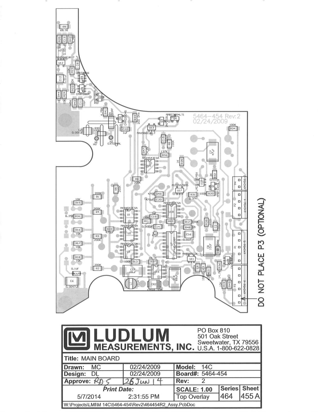
44 Model 14C-RK Response Kit Technical Manual Section 11 Section 11 Parts List Model 14C Survey Meter Reference Description Part Number UNIT Completely Assembled Model 14C Survey Meter Main Board, Drawing BOARD Completely Assembled Main Circuit Board CAPACITORS TRANSISTORS C1 47pF, 50V C2 100pF, 100V C3 100pF, 100V C4 100pF, 3KV C5 0.1µF, 35V C µF, 100V C7 47µF, 10V C8 10µF, 25V C9 1µF, 16V C10 470pF, 100V C11 10pF, 100V C µF, 50V C13-C µF, 100V C15 100pF, 100V C µF, 50V C17 68µF, 10V C18 68µF, 10V C19 1µF, 16V C20 470pF, 100V C µF, 2KV Q1 MMBT4403LT Q2 MMBT3904LT Q3 2N7002L Q4 MMBT3904LT Ludlum Measurements, Inc. Page 11-1 April 2015
45 Model 14C-RK Response Kit Technical Manual Section 11 Reference Description Part Number INTEGRATED CIRCUITS DIODES SWITCHES POTENTIOMETERS RESISTORS U1-U3 MAX4542ESA U5 MAX4543ESA U7 CD74HC4538M U8-U9 CMXT U10 LMC7111BIM5X U11 MAX985EUK-T U12-U13 MAX986EUK-T U15 CMXT U16 LT1304CS U17 MIC1557BM U18 MAX4543ESA CR1 CMPD2004S CR2 CMSH1-40M S1 CENTRAL-2P6P, (RANGE) S2 7101SDCQE, F/S S3 TP11LTCQE, RESET S4 TP11LTCQE, BAT TEST S5 7101SDCQE, AUDIO R14 250K, 64W254, 1K R27 250K, 64W254, R28 500K, 64W504, R29 250K, 64W254, R30 250K, 64W254, R1-R6 200K, 1/8W, 1% R7-R8 100K, 1/8W, 1% R9 68.1K, 1/8W, 1% R10-R13 100K, 1/8W, 1% R15-R19 10K, 1/8W, 1% R20 100K, 1/8W, 1% R K, 1/8W, 1% R22-R24 10K, 1/8W, 1% R K, 7/8W, 1% R K, 1/8W, 1% R K, 1/8W, 1% R32 2K, 1/8W, 1% R Ohm, 1/8W, 1% R34 100K, 1/8W, 1% R35 1K, 1/4W, 1% Ludlum Measurements, Inc. Page 11-2 April 2015
46 Model 14C-RK Response Kit Technical Manual Section 11 Reference Description Part Number R K, 1/8W, 1% R K, 1/8W, 1% R38-R39 200K, 1/8W, 1% R40 100K, 1/8W, 1% R41-R K, 1/8W, 1% R43 165K, 1/8W, 1% R44-R45 1K, 1/8W, 1% R46 137K, 1/8W, 1% R K, 1/8W, 1% R48 1M, 1/8W, 1% R49 475K, 1/8W, 1% CONNECTORS INDUCTOR MISCELLANEOUS P , MTA100 5, CHASSIS CONNECTOR P , MTA100 4, HV/ 1K DET CONNECTOR P , MTA100 6, ACCESSORY P , MTA100 2, SPEAKER L1 22uH W1 HV WIRE ** W1 EXT. DET. WIRE ** HV Power Supply Board, Drawing BOARD Completely Assembled HV Power Supply Board CAPACITORS INTEGRATED CIRCUIT DIODES C1 10uF, 25V C2-C uF, 2KV C6 100PF, 3KV C7-C uF, 500V C13 68uF, 10V C14 0.1uF, 50V U1 LT1304CS CR1-CR6 CMSD2004S CR7 CMSH1-40M Ludlum Measurements, Inc. Page 11-3 April 2015
47 Model 14C-RK Response Kit Technical Manual Section 11 Reference Description Part Number POTENTIOMETERS RESISTORS CONNECTORS TRANSFORMER DETECTOR MISCELLANEOUS Wiring Diagram, Drawing AUDIO CONNECTORS BATTERY MISCELLANEOUS R3 25K, 8026EKX-253, OL ADJ R8 1M, 3266W1-105, HV ADJ R1 1.5M, 1/4W, 1% R2 100K, 1/4W, 1% R4 1M, 1/4W, 1% R5 4.75K, 1/4W, 1% R6 500M, 3KV, 2% R7 475K, 1/4W, 1% R9 1M, 1/4W, 1% P , MTA100 2, 1K TEST P , MTA100 4 HV/1K DET T R V1 LND W1 TEFLON WHITE EE22, HV W2 #22 BLACK UL1430, NOT USED DS1 UNIMORPH J MTA J MTA J MTA J4-J MTA J MTA B1-B2 "D" DURACELL BATTERY FL2-FL4 WIRE ** W1 RECPT-UG706/U C LMI M1 METER MOVEMENT * CABLE-C (STD 39-inch) * M14C BATTERY BOX LID WITH LATCH SET * BATT. CONTACT ASSY * CALIBRATION COVER WITH SCREWS Ludlum Measurements, Inc. Page 11-4 April 2015
48 Model 14C-RK Response Kit Technical Manual Section 11 Reference Description Part Number * BEZEL W/MOVEMENT ASSY * PORTABLE BEZEL GLASS W/O SCREWS * PORTABLE KNOB * CAN ASSEMBLY O-RING * LATCH KIT W/O BATTERY LID * PORTABLE HANDLE FOR CLIP WITH SCREWS * PROBE CLIP * CHECK SOURCE 137 Cs 37 kbq 1uCi * CHECK SOURCE HOLDER * CARRYING CASE Model 44-9 Alpha-Beta- Gamma Detector (PANCAKE) UNIT Completely Assembled Model 44-9 Alpha-Beta- Gamma Detector * DETECTOR BODY * HANDLE GRIP * G-M TUBE (LND 7311) TGM N * SOCKET SET SCREWS (10-34 X 1/4), 3 EACH * PENCIL CLIP * RESISTOR, 3.3 MEGOHMS * CONNECTOR, UG 706/U * HV WIRE * PROTECTIVE SCREEN * RED PROTECTIVE CAP Model 44-2 Gamma Scintillator UNIT Completely Assembled Model 44-2 Gamma Scintillator * DETECTOR BODY * END CAP * 1 1 inch Nal CRYSTAL * 1.5 inch TUBE/SOCKET ASSY * TUBE SHIELD Ludlum Measurements, Inc. Page 11-5 April 2015
49 Model 14C-RK Response Kit Technical Manual Section 11 Reference Description Part Number * PM TUBE * CONNECTOR UG 706/U * TEFLON WIRE 4 ea * #26 BLACK WIRE 4 ea * LUG * SCREWS 4 ea * SPONGE 6 ea * XTAL SIDE SPONGE 2 ea BOARD Completely Assembled Tube Socket Circuit Board Included in PM TUBE Ludlum Measurements, Inc. Page 11-6 April 2015
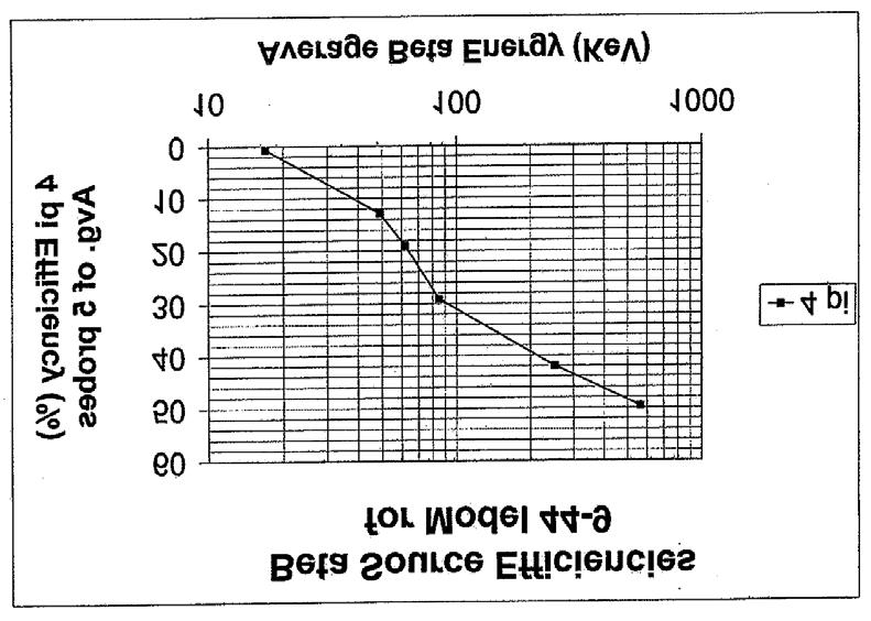
50 Model 14C-RK Response Kit Technical Manual Section 12 Section 12 Drawings Main Board, Drawing (4 sheets) Main Board Component Layout, Drawing A (2 sheets) HV Power Supply Board, Drawing HV Power Supply Board Component Layout, Drawing Wiring Diagram, Drawing Model 44-9 Alpha, Beta, Gamma Detector, Drawing 2 x 206 Energy Response for Ludlum Model 44-9 New Beta Source Efficiencies for Model 44-9 Model 44-2 Gamma Scintillator, Assembly View, Drawing 2 x 205A 1.5 inch Tube Socket Board Component Layout, Drawing 2 x inch Tube Socket Board Schematic, Drawing 2 x 317 Energy Response Curve Model 44-2 Ludlum Measurements, Inc. Page 12-1 April 2015
51
52
53
54
55
56
57
58
59
60
61
LUDLUM MODEL SURVEY METER. March 2017 Serial Number and Succeeding Serial Numbers, And serial Numbers , ,
 LUDLUM MODEL 193-6 SURVEY METER March 2017 Serial Number 296865 and Succeeding Serial Numbers, And serial Numbers 294894, 294903, 294918 LUDLUM MODEL 193-6 SURVEY METER March 2017 Serial Number 296865
LUDLUM MODEL 2403 POCKET SURVEY METER. November 2010 Serial Number and Succeeding Serial Numbers
 LUDLUM MODEL 2403 POCKET SURVEY METER November 2010 Serial Number 163845 and Succeeding Serial Numbers LUDLUM MODEL 2403 POCKET SURVEY METER November 2010 Serial Number 163845 and Succeeding Serial Numbers
LUDLUM MODEL 2402 POCKET SURVEY METER. January 2015 Serial Number and Succeeding Serial Numbers
 LUDLUM MODEL 2402 POCKET SURVEY METER January 2015 Serial Number 159636 and Succeeding Serial Numbers LUDLUM MODEL 2402 POCKET SURVEY METER January 2015 Serial Number 159636 and Succeeding Serial Numbers
LUDLUM MODELS 2401-ECA, 2401-EWA, 2401-EC2A AND 2401-PA POCKET SURVEY METERS WITH ALARM
 LUDLUM MODELS 2401-ECA, 2401-EWA, 2401-EC2A AND 2401-PA POCKET SURVEY METERS WITH ALARM September 2011 Serial Number 143446 and Succeeding Serial Numbers LUDLUM MODELS 2401-ECA, 2401-EWA, 2401-EC2A AND
LUDLUM MODEL RK2 RESPONSE KIT. October 2017 Serial Number and Succeeding Serial Numbers
 LUDLUM MODEL 2241-3RK2 RESPONSE KIT October 2017 Serial Number 238342 and Succeeding Serial Numbers LUDLUM MODEL 2241-3RK2 RESPONSE KIT October 2017 Serial Number 238342 and Succeeding Serial Numbers STATEMENT
LUDLUM MODEL RK RESPONSE KIT. January 2016 Serial Number and Succeeding Serial Numbers
 LUDLUM MODEL 2241-2RK RESPONSE KIT January 2016 Serial Number 237627 and Succeeding Serial Numbers LUDLUM MODEL 2241-2RK RESPONSE KIT January 2016 Serial Number 237627 and Succeeding Serial Numbers STATEMENT
LUDLUM MODEL AND LUDLUM MODEL ALPHA, BETA, & GAMMA DETECTORS
 LUDLUM MODEL 44-9-18 AND LUDLUM MODEL 44-9-19 ALPHA, BETA, & GAMMA DETECTORS January 2018 Serial Number PR254331 and Succeeding Serial Numbers LUDLUM MODEL 44-9-18 AND LUDLUM MODEL 44-9-19 ALPHA, BETA,
LUDLUM MODEL ALPHA, BETA, GAMMA HAND DETECTOR. June 2016 Serial Number and Succeeding Serial Numbers
 LUDLUM MODEL 44-25 ALPHA, BETA, GAMMA HAND DETECTOR June 2016 Serial Number 155835 and Succeeding Serial Numbers LUDLUM MODEL 44-25 ALPHA, BETA, GAMMA HAND DETECTOR June 2016 Serial Number 155835 and
LUDLUM MODEL 44-2 GAMMA SCINTILLATOR. February 2018 Serial Number PR and Succeeding Serial Numbers
 LUDLUM MODEL 44-2 GAMMA SCINTILLATOR February 2018 Serial Number PR361009 and Succeeding Serial Numbers LUDLUM MODEL 44-2 GAMMA SCINTILLATOR February 2018 Serial Number PR361009 and Succeeding Serial
LUDLUM MODEL 44-9 ALPHA, BETA, GAMMA DETECTOR. February 2010 Serial Number PR and Succeeding Serial Numbers
 LUDLUM MODEL 44-9 ALPHA, BETA, GAMMA DETECTOR February 2010 Serial Number PR090405 and Succeeding Serial Numbers LUDLUM MODEL 44-9 ALPHA, BETA, GAMMA DETECTOR February 2010 Serial Number PR090405 and
LUDLUM MODEL 44-3 LOW ENERGY GAMMA SCINTILLATOR. May 2018 Serial Number PR and Succeeding Serial Numbers
 LUDLUM MODEL 44-3 LOW ENERGY GAMMA SCINTILLATOR May 2018 Serial Number PR134823 and Succeeding Serial Numbers LUDLUM MODEL 44-3 LOW ENERGY GAMMA SCINTILLATOR May 2018 Serial Number PR134823 and Succeeding
Portable Survey Instruments NISP-RP-01
 NUCLEAR INDUSTRY STANDARD PROCESS Radiological Protection NISP-RP-01 This is an industry document for standardizing radiation protection processes used by supplemental radiation protection technicians.
LUDLUM MODEL 44-7 Alpha, Beta, Gamma Detector. July 2012 Serial No. PR and succeeding Serial Numbers
 LUDLUM MODEL 44-7 Alpha, Beta, Gamma Detector July 2012 Serial No. PR090405 and succeeding Serial Numbers LUDLUM MODEL 44-7 Alpha, Beta, Gamma Detector July 2012 Serial No. PR090405 and succeeding Serial
LUDLUM MODEL 25 AND 25-1 PERSONAL RADIATION MONITOR USER S MANUAL. October 2014 Serial Number and Succeeding Serial Numbers
 LUDLUM MODEL 25 AND 25-1 PERSONAL RADIATION MONITOR USER S MANUAL October 2014 Serial Number 25000100 and Succeeding Serial Numbers LUDLUM MODEL 25 AND 25-1 PERSONAL RADIATION MONITOR USER S MANUAL October
Identify the following features and specifications for the ESP1
 LEARNING OBJECTIVES: 2.17.01 List the factors which affect an RCT's selection of a portable contamination monitoring instrument, and identify appropriate instruments for contamination monitoring. (Also
LUDLUM MODEL 19A. Micro R Meter. May 2017 Serial No and Succeeding Serial Numbers
 LUDLUM MODEL 19A Micro R Meter May 2017 Serial No. 144020 and Succeeding Serial Numbers LUDLUM MODEL 19A Micro R Meter May 2017 Serial No. 144020 and Succeeding Serial Numbers Model 19A Micro R Meter
NUCLEAR INDUSTRY STANDARD PROCESS Radiological Protection. Level 3 Information Use
 NUCLEAR INDUSTRY STANDARD PROCESS Radiological Protection Level 3 Information Use NISP-RP-001 Industry Approval Date: September 14, 2018 This is an industry document for standardizing radiation protection
MODEL 23 AND 23-1 ELECTRONIC PERSONAL DOSIMETER. August 2017
 MODEL 23 AND 23-1 ELECTRONIC PERSONAL DOSIMETER August 2017 MODEL 23 AND 23-1 ELECTRONIC PERSONAL DOSIMETER August 2017 ii STATEMENT OF WARRANTY Ludlum Measurements, Inc. warrants the products covered
HEALTH AND SAFETY MANUAL
 HEALTH AND SAFETY MANUAL Title: Ionizing Radiation Approved by: Greg Savoy Rev. 3/1/13 1.0 Purpose The purpose of this safety policy is to establish guidelines for the protection and safety of Compay employees
Radiation Safety and Equipment Considerations. Bonnie Meilner Regional Sales Manager LAURUS Systems Inc.
 Radiation Safety and Equipment Considerations Bonnie Meilner Regional Sales Manager LAURUS Systems Inc. bonnie.meilner@laurussystems.com COPYRIGHT LAURUS SYSTEMS INC - 2013 Why do you need Radiation Detectors
LUDLUM MODEL and PANCAKE CLUSTER DETECTORS. June 2016
 LUDLUM MODEL 44-89 and 44-94 PANCAKE CLUSTER DETECTORS June 2016 LUDLUM MODEL 44-89 and 44-94 PANCAKE CLUSTER DETECTORS June 2016 STATEMENT OF WARRANTY Ludlum Measurements, Inc. warrants the products covered
LUDLUM MODEL 26 FRISKER USER S MANUAL. December 2016 Serial Number PF and Succeeding Serial Numbers
 LUDLUM MODEL 26 FRISKER USER S MANUAL December 2016 Serial Number PF001075 and Succeeding Serial Numbers LUDLUM MODEL 26 FRISKER USER S MANUAL December 2016 Serial Number PF001075 and Succeeding Serial
CONTAMINATION MONITORING INSTRUMENTATION RCT STUDY GUIDE LEARNING OBJECTIVES:
 LEARNING OBJECTIVES: 2.17.01 List the factors which affects an RCT's selection of a portable contamination monitoring instrument. 2.17.02 Describe the following features and specifications for commonly
MODEL AND MODEL GAS PROPORTIONAL DETECTORS. December 2016 Serial No and Succeeding Serial Numbers
 MODEL 43-37 AND MODEL 43-37-1 GAS PROPORTIONAL DETECTORS Serial No. 086152 and Succeeding Serial Numbers MODEL 43-37 AND MODEL 43-37-1 GAS PROPORTIONAL DETECTORS Serial No. 086152 and Succeeding Serial
DOE 2.17 Contamination Monitoring Instrumentation Study Guide. 00ICP330 Rev. 0 Page 1 of 23
 00ICP330 Rev. 0 Page 1 of 23 Course Title: Radiological Control Technician Module Title: Contamination Monitoring Instrumentation Module Number: 2.17 Objectives: 2.17.01 List the factors which affects
LUDLUM MODEL 26-1 FRISKER USER S MANUAL. April 2017 Serial Number PF and Succeeding Serial Numbers
 LUDLUM MODEL 26-1 FRISKER USER S MANUAL April 2017 Serial Number PF002366 and Succeeding Serial Numbers LUDLUM MODEL 26-1 FRISKER USER S MANUAL April 2017 Serial Number PF002366 and Succeeding Serial Numbers
Radiation Alert Frisker INTERNATIONAL
 Radiation Alert Frisker INTERNATIONAL S.E. International, Inc. P.O. Box 39, 436 Farm Rd. Summertown, TN 38483 USA 1.800.293.5759 931.964.3561 Fax: 1.931.964.3564 www.seintl.com radiationinfo@seintl.com
HEALTH AND SAFETY PROGRAM 406 IONIZING/NONIONIZING RADIATION PROTECTION
 Page 1 of 11 1.0 PURPOSE Axiall, Plaquemine Complex, maintains various sources of ionizing and nonionizing radiation throughout the complex. Ionizing radiation sources include density gauges and PMI Analyzers.
Nuclear Associates
 Nuclear Associates 05-575 MiniMonitor III Multipurpose X and Gamma Ray Survey Meter Operators Manual February 2005 Manual No. 05-575-1 Rev. 2 2004, 2005 Fluke Corporation, All rights reserved. Printed
RAM GENE-1 ERK. Contamination & Radiation Meter. Operating Manual. Document #PRIR90N2.DOC Version 2.2 October 2009
 RAM GENE-1 ERK MK-Ι & MK-ΙΙ Contamination & Radiation Meter Operating Manual Document #PRIR90N2.DOC Version 2.2 October 2009 Version / Revision Log: RAM GENE-1 ERK/ Operating Manual Ver./Rev.# Date Revised
Radiation Training for Ancillary Personnel. Introduction
 Radiation Training for Ancillary Personnel Introduction A number of Oklahoma State University Center for Health Sciences (CHS) laboratories use radioactive materials.the Radiation Safety Officer has developed
RAM GENE / RAM GENE-1
 RAM GENE / RAM GENE-1 Radiation Meters Operating Manual Document #PRIR69N0.DOC Version 6.1 - December 2000 ROTEM INDUSTRIES LTD. ROTEM Industrial Park P.O.Box 9046, Beer-Sheva 84190, ISRAEL Tel: 972-8-6571312/6568652
Surface Contamination Monitor. Operation Manual
 Surface Contamination Monitor Operation Manual 1996, 2005, 2013, 2014, 2015 IMI-International Medcom, Inc. All rights reserved. Contents 1 Introduction...1 How the IMI Inspector Alert Detects Radiation...
LUDLUM MODEL ALARM RATEMETER. June 2017 Serial Number and Succeeding Serial Numbers
 LUDLUM MODEL 177-61 ALARM RATEMETER June 2017 Serial Number 101825 and Succeeding Serial Numbers LUDLUM MODEL 177-61 ALARM RATEMETER June 2017 Serial Number 101825 and Succeeding Serial Numbers STATEMENT
Relevant Radon properties
 Relevant Radon properties Radon is a natural gas and has a half life of 3.8 days. This means that if a box was full of radon gas, half of it would have decayed into something else after 3.8 days. It has
Dosimeters/Survey meters
 Dosimeters/Survey meters 40 Gracechurch Str., EC3V OBT, London, United Kingdom (24 Hour Customer Line) 0044 208 720 6926 RAD-ION (RI-02) Especially designed for the Detection of Pulsed (Golden Engineering)
Radioactivity dosimeter RD01. User's Manual
 Radioactivity dosimeter RD01 User's Manual 2011 Contents Introduction 2 Technical specifications 4 How does RD01 work? 5 How to use RD01? 7 Power 10 How to carry out measures correctly? 11 Warranty 12
Detecting Radiation. Protection through Detection. February Animations in this training work best in Windows XP
 Saudi Arabia : info_ksa@magusintl.com U.A.E : info_uae@magusintl.com Detecting Radiation Animations in this training work best in Windows XP February 2006 Why Detect Radiation Today? Medicine Imaging Cancer
COUNTING ROOM EQUIPMENT RCT STUDY GUIDE
 LEARNING OBJECTIVES: 2.19.01 Describe the features and specifications for commonly used laboratory counters or scalers: a. Detector type b. Detector shielding c. Detector window d. Types of radiation detected
NSAW Radon Assessment 2017 QUESTIONS AND ANSWERS
 NSAW Radon Assessment 2017 QUESTIONS AND ANSWERS Q. Why are you testing for radon? A. Testing is a key component of the Navy Radon Assessment and Mitigation Program. Q. Can you simply test for radon outside
A Continuous Air Monitoring Sampler for 125 I - RIS-125
 A Continuous Air Monitoring Sampler for 125 I - RIS-125 S.Levinson, I.Belaish, T.Kravchik, U.German, O.Pelled, Y. Laichter, Y.Mazor, U.Wengrowicz, E.Dolev, H.Assido, D.Tirosh Nuclear Research Center Negev,
PORTABLE ISOTOPE IDENTIFIER Search Tool / Sample Counting System
 FEATURES: HIGH GAMMA SENSITIVITY MULTI-CHANNEL ANALYZER (MCA) WORKS WITH VARIETY OF PROBES RADIONUCLIDE LIBRARY TAILORED TO CUSTOMER REQUEST SIMULTANEOUSLY MEASURES ; DISPLAYS; ALARMS 1-3 SEPARATE DETECTORS
Kata products Kata DGM-1500 Turva
 Kata DGM-1500 Turva RADIATION DETECTED: Gamma and X-ray MEASUREMENT UNITS: microsv/h (μsv/h) LINEAR RANGE: Dose rate 0.01-100 000 microsv/h Dose 0.001-1000 millisv SENSITIVITY: 150 cpm/microsv/h ACCURACY:
Radiation Safety Guidelines for Non-Users
 Radiation Safety Guidelines for Non-Users This is a Read and Sign Awareness Training document. You should read and sign this document if you: 1. DO NOT work directly with radioactive materials or other
DMC 2000 Personal Electronic Dosimeter
 DMC 2000 Personal Electronic Dosimeter Accurate Dose And Dose Rate Measurement Pre-Set Audible And Visual Alarms Small Lightweight Design PROTECTION BEGINS WITH DETECTION The fi rst step in providing hazard
AERIAL RADIATION DETECTORS
 DRONE READY AERIAL RADIATION DETECTORS DroneSENSOR TM Series Model ~ DroneRAD-ST TM (Search Tool or Mapping) - Gamma Model ~ DroneRAD-P TM (Air Monitor& Plume Detector) Particulate Alpha, Beta, Gamma &
NEX-BETA-ABG FACILITY Drinking Water Safety Monitor
 NEX-BETA-ABG FACILITY Drinking Water Safety Monitor FEATURES: DETECTS ALPHA, BETA AND GAMMA RADIATION AVAILABLE IN PORTABLE OR INSTALLED VERSION MEASURES AT OR BELOW EPA/DHS PAG LEVELS PROTECTIVE ACTION
RK CO 2 Transmitter Operator s Manual
 65-2397RK CO 2 Transmitter Operator s Manual Part Number: 71-0185RK Revision: B Released: 7/18/14 RKI Instruments, Inc. www.rkiinstruments.com WARNING Read and understand this instruction manual before
LUDLUM MODEL 3276 SERIES FRISKER/AREA MONITOR USER S MANUAL. November 2017 Serial Number: and Succeeding Firmware: 49830n30 and Higher
 LUDLUM MODEL 3276 SERIES FRISKER/AREA MONITOR USER S MANUAL November 2017 Serial Number: 25009185 and Succeeding Firmware: 49830n30 and Higher LUDLUM MODEL 3276 SERIES FRISKER/AREA MONITOR USER S MANUAL
RADON LAZERWEB SERVICES
 RADON LAZERWEB SERVICES WWW.LAZERWEBSITES.COM Contents Overview...2 Radon is estimated to cause thousands of lung cancer deaths in the U.S. each year...2 Radon is a cancer causing, radioactive gas...2
PRELIMIN INTERNATIONAL
 INTERNATIONAL S.E. International, Inc. P.O. Box 39, 436 Farm Rd. Summertown, TN 38483 USA 1.800.293.5759 931.964.3561 Fax: 1.931.964.3564 www.seintl.com radiationinfo@seintl.com Contents Chapter 1: Introduction
MINI-RADIAC INTRODUCTION
 THE MINI-RADIAC IS A PERSONAL DOSIMETER/RADIATION MONITOR. IT IS USED TO DETECT ACCUMULATED DOSE AND/OR RATE OF RADIATION EXPOSURE. IT IS DESIGNED TO ALERT AND INFORM THE WEARER OF THE PRESENCE OF GAMMA
LUDLUM MODEL 2360 SCALER/RATEMETER DATA LOGGER. July 2016 Serial Number and Succeeding Serial Numbers
 LUDLUM MODEL 2360 SCALER/RATEMETER DATA LOGGER July 2016 Serial Number 133669 and Succeeding Serial Numbers LUDLUM MODEL 2360 SCALER/RATEMETER DATA LOGGER July 2016 Serial Number 133669 and Succeeding
Ramon 2.2 Radon-Monitor
 Ramon 2.2 Radon-Monitor Applications Measurement Modes - Technology - Quality Extratech Engineering, Technology, Software & Training - by 3DLiFe srl Via Torraca, 76-85100 Potenza (PZ) Tel/Fax. (+39) 0971.21.432
Using the GammaRAE II Personal Radiation Detector
 Using the GammaRAE II Personal Radiation Detector GammaRAE II Features Normal Usage Turning Unit On Operating Mode User Screens Advanced Features Programming Mode Training Agenda GammaRAE II Features Detector:
Radon Measurement Survey Report. McKnight School Service Center 417 Fifth Street Aurora, Illinois Prepared For:
 Radon Measurement Survey Report Site: 417 Fifth Street Aurora, Illinois 60505 Survey Dates: May 9, 2018 thru May 11, 2018 Prepared For: East Aurora School District 131 417 Fifth Street Aurora, Illinois
HP 101A Series Humidity Temperature Probes INSTRUCTION MANUAL
 HP 101A Series Humidity Temperature Probes INSTRUCTION MANUAL -2- CONTENTS DESCRIPTION... 3 OPERATION... 4 MEASUREMENT... 5 MAINTENANCE... 7 CALIBRATION BASICS... 8 CALIBRATION PROCEDURE... 10 SPECIFICATIONS...
User s Manual. Electronic Personal Dosimeter (For Gamma(X)-ray) NRF30. Fuji Electric Co., Ltd. TN514629i 1/31
-ray) NRF30. Fuji Electric Co., Ltd. TN514629i 1/31") User s Manual Electronic Personal Dosimeter (For Gamma(X)-ray) NRF30 Fuji Electric Co., Ltd. TN514629i 1/31 Introduction Thank you for purchasing the Electronic Personal Dosimeter NRF30 (Hereinafter described
User s Manual Electronic Personal Dosimeter (For Gamma(X)-ray) NRF30 Fuji Electric Co., Ltd. TN514629i 1/31 Introduction Thank you for purchasing the Electronic Personal Dosimeter NRF30 (Hereinafter described
Radiation Monitoring Systems
 Radiation Monitoring Systems Certificate No. 3250 Contents A guide to Southern Scientific radiation monitoring systems Area Gamma & Interlock Systems (page 3) AGM3 AUTOMESS 6150 Contamination Monitors
275HVD NON-CONTACT, HIGH VOLTAGE DETECTOR DETECTOR DE ALTA TENSIÓN SIN CONTACTO
 99 Washington Street Melrose, MA 02176 Phone 781-665-1400 Toll Free 1-800-517-8431 Visit us at www.testequipmentdepot.com 275HVD NON-CONTACT, HIGH VOLTAGE DETECTOR DETECTOR DE ALTA TENSIÓN SIN CONTACTO
RK Hydrogen Sulfide Transmitter Operator s Manual
 65-2331RK Hydrogen Sulfide Transmitter Operator s Manual Part Number: 71-0176RK Revision: B Released: 11/26/14 RKI Instruments, Inc. www.rkiinstruments.com WARNING Read and understand this instruction
Using the GammaRAE II Responder Personal Radiation Detector and Dosimeter in One. Firmware Version 3.00 D August 2006
 Using the GammaRAE II Responder Personal Radiation Detector and Dosimeter in One Firmware Version 3.00 D August 2006 GammaRAE II Responder Features Getting Started Replacing the batteries Turn the unit
LUDLUM MODEL ALPHA/BETA RATEMETER. April 2018 Serial No and Succeeding Serial Numbers
 LUDLUM MODEL 177-84 ALPHA/BETA RATEMETER April 2018 Serial No. 128600 and Succeeding Serial Numbers LUDLUM MODEL 177-84 ALPHA/BETA RATEMETER April 2018 Serial No. 128600 and Succeeding Serial Numbers STATEMENT
Radon Measurement Survey Report. Krug Elementary School 240 Melrose Avenue Aurora, Illinois Prepared For:
 Radon Measurement Survey Report Site: 240 Melrose Avenue Aurora, Illinois 60505 Survey Dates: May 1, 2018 thru May 3, 2018 Prepared For: East Aurora School District 131 417 Fifth Street Aurora, Illinois
ALPHA Radiation Safety Manual
 ALPHA Radiation Safety Manual CONTACT INFORMATION In order to request radiation safety assistance or service during normal hours contact: IUB Radiation Safety Officer. 855-3230 Assistant Radiation Safety
Using downhole probing for real-time grade estimation for uranium exploration and mining
 February 2015 Using downhole probing for real-time grade estimation for uranium exploration and mining Andrew Fitzpatrick Chief Geophysicist cameco.com Radiation 101 2 Using downhole probing for Uranium
California State University Bakersfield Radiation Safety Program Revised November 2017
 California State University Bakersfield Radiation Safety Program Revised November 2017 THIS PAGE INTENTIONALLY LEFT BLANK 1 Contents 1. INTRODUCTION... 3 2. ACQUISITION... 3 4. STORAGE... 3 5. LABELING...
Area Monitor/Frisker Count Rate Meter Victoreen
 Area Monitor/Frisker Count Rate Meter Victoreen Model 190F! Adjustable Alarm! Backlit analog/digital display! Interchangeable probe adapter module! Multiple probe use! Redundant power supply! Available
A FIRST RESPONDERS GUIDE TO PURCHASING RADIATION PAGERS
 EML-624 A FIRST RESPONDERS GUIDE TO PURCHASING RADIATION PAGERS FOR HOMELAND SECURITY PURPOSES Paul Bailey Environmental Measurements Laboratory U.S. Department of Homeland Security 201 Varick Street,
Fundamentals is subdivided into Sources of Radiation, Biological Effects, Mathematics, Chemistry, Physics, and Units and Terminology.
 NRRPT Exam Review Class - an intensive 5-day class designed to prepare the candidate to successfully pass the NRRPT Exam. The course concentrates on the basic tools the candidate needs to successfully
Radon Measurement Survey Report. Oak Park Elementary School 1200 Front Street Aurora, Illinois Prepared For:
 Radon Measurement Survey Report Site:July 5, 2018 1200 Front Street Aurora, Illinois 60505 Survey Dates: May 9, 2018 thru May 11, 2018 Prepared For: East Aurora School District 131 417 Fifth Street Aurora,
Radon Measurement Survey Report. Waldo Middle School 56 Jackson Street Aurora, Illinois Prepared For:
 Radon Measurement Survey Report Site: 56 Jackson Street Aurora, Illinois 60505 Survey Dates: May 8, 2018 thru May 10, 2018 Prepared For: East Aurora School District 131 417 Fifth Street Aurora, Illinois
Radon Measurement Survey Report. Rollins Elementary School 950 Kane Street Aurora, Illinois Prepared For:
 Radon Measurement Survey Report Site: 950 Kane Street Aurora, Illinois 60505 Survey Dates: May 15, 2018 thru May 18, 2018 Prepared For: East Aurora School District 131 417 Fifth Street Aurora, Illinois
EcotestVIP PERSONAL RADIOACTIVITY DETECTOR. Operating manual ВIСТ РЭ
 EcotestVIP PERSONAL RADIOACTIVITY DETECTOR Operating manual ВIСТ.412129.020-02 РЭ The enterprise works in accordance with the introduced and certificated Quality Management System in compliance with the
Portable Alpha/Beta Continuous Online Air Monitor (CAM)
") Aer 5000 Desktop Portable Alpha/Beta Continuous Online Air Monitor (CAM) The Aer5200 monitors the ambient air continuously to detect airborne radioactive aerosols (LLRD). Typical application fields are
Aer 5000 Desktop Portable Alpha/Beta Continuous Online Air Monitor (CAM) The Aer5200 monitors the ambient air continuously to detect airborne radioactive aerosols (LLRD). Typical application fields are
Victoreen Primalert 35 Area Radiation Monitor
 Victoreen 05-437 Primalert 35 Area Radiation Monitor Operators Manual March 2005 Manual No. 126011 Rev. 3 2003, 2005 Fluke Corporation, All rights reserved. Printed in U.S.A. All product names are trademarks
Comprehensive applications of the gas flow proportional counters for Radiological Surveillance
 Comprehensive applications of the gas flow proportional counters for Radiological Surveillance D.A.R.Babu, Anand Raman, Ashokkumar P and D.N.Sharma Radiation Safety Systems Division, Bhabha Atomic Research
Ranger EXP RADIATION A L E R T
 RADIATION A L E R T TM Ranger EXP INTERNATIONAL S.E. International, Inc. P.O. Box 39, 436 Farm Rd. Summertown, TN 38483 USA 1.800.293.5759 1.931.964.3561 Fax: 1.931.964.3564 www.seintl.com radiationinfo@seintl.com
RK-05 Combustible Gas Transmitter Operator s Manual
 65-2405RK-05 Combustible Gas Transmitter Operator s Manual Part Number: 71-0180RK Revision: 0 Released: 2/16/11 RKI Instruments, Inc. www.rkiinstruments.com WARNING Read and understand this instruction
Instrumentation. Post RDD Event Urban Reoccupancy. James P. Menge PE. The world leader in serving science
 The world leader in serving science Instrumentation Post RDD Event Urban Reoccupancy James P. Menge PE Perception In the aftermath of a radiological emergency the public will see radiation and its potential
PORTABLE or FIXED PERSONNEL & VEHICLE MONITOR
 _ PORTABLE or FIXED PERSONNEL & VEHICLE MONITOR FEATURES: COMPLETELY PORTABLE OR WALL INSTALLATION CAN BE SET TO ANY WIDTH; QUICK SET UP VIDEO REAL-TIME DISPLAY & CAPTURE OPTIONAL: WIRELESS REMOTE NOTIFICATION
INDOOR RADON POLICY AND PROCEDURES LAWLER WOOD HOUSING, LLC
 INDOOR RADON POLICY AND PROCEDURES LAWLER WOOD HOUSING, LLC Prepared for Lawler-Wood Housing, LLC Riverview Tower, Suite 2000 900 South Gay Street Knoxville, Tennessee Prepared by ORION Orion Environmental
Environmental Radiation Monitoring System
 Environmental Radiation Monitoring System Toshihiro Takagi Osamu Kimura Atsushi Minagoshi 1. Introduction In order to ascertain conditions near the perimeter of a supervised area at a nuclear power plant
DIGITAL AREA RADIATION MONITOR
 RADIATION DETECTION AND MONITORS 103 AREAEXPERT DIGITAL AREA RADIATION MONITOR Touch screen LCD Colorful visual and audio indications Network compatible with CenterExpert software PC controllable Easily
H-10PM. Refrigerant Leak Detector
 H-10PM Refrigerant Leak Detector Congratulations! You have just purchased the most versatile, high performance service leak detector available in the industry today. It will detect refrigerants with a
AERIAL RADIATION & CHEMICAL DETECTION SYSTEM. DroneSENSOR TM Series. Particulate Alpha, Beta, Gamma & Airborne Chemicals
 DroneSENSOR TM Series Model ~ DroneRAD-ST TM (Search Tool or Mapping) - Gamma Model ~ DroneRAD-P TM (Air Monitor & Plume Detector) Particulate Alpha, Beta, Gamma & Airborne Chemicals DroneSENSOR TM THE
Real-Time Remote Monitoring System Utilizing New Electronic Personal Dosimeter
 Real-Time Remote Monitoring System Utilizing New Electronic Personal Dosimeter NAKASHIMA, Sadao * MAEKAWA, Osamu * ABE, Shigeru * A B S T R A C T Conventional radiation exposure management methods included
CA870 INFRARED THERMOMETER E N G L I S H. User Manual. Auto OFF
 INFRARED THERMOMETER CA870 Auto OFF E N G L I S H User Manual Owner s Record The serial number for the Model CA870 is located inside the battery compartment of the instrument. Please record this number
Package Contents. Dry Block Heater Power Cord Instruction manual Warranty Card. Serial Number: Date of Purchase: Supplier: Table of Contents
 - English... 1 Instruction Manual Analog, Dry Block Heater, 1 Block, HB1AL Analog, Dry Block Heater, 2 Block, HB2AL Analog, Dry Block Heater, 4 Block, HB4AL Analog, Dry Block Heater, 6 Block, HB6AL Digital,
Our Extended Personal Electronic Dosimeter (PED) Family
 Family") Our Extended Personal Electronic Dosimeter (PED) Family Tracerco s Award Winning Radiation Monitors and Servicing business unit provides a range of products and services accredited to ISO9001:2008 and
Our Extended Personal Electronic Dosimeter (PED) Family Tracerco s Award Winning Radiation Monitors and Servicing business unit provides a range of products and services accredited to ISO9001:2008 and
STUDY #3 IN A SERIES OF REPORTS ON RADON IN BC HOMES. Castlegar: COMMUNITY-WIDE RADON TESTING RESULTS AS PART OF ITS. PROGRAm
 STUDY #3 IN A SERIES OF REPORTS ON RADON IN BC HOMES Castlegar: COMMUNITY-WIDE RADON TESTING RESULTS AS PART OF ITS PROGRAm BC Lung Association The British Columbia Lung Association (BCLA) is one of the
MP 601A Humidity Probe INSTRUCTION MANUAL
 MP 601A Humidity Probe INSTRUCTION MANUAL CONTENTS DESCRIPTION... 3 OPERATION... 3 WIRING... 5 INSTALLATION... 7 MAINTENANCE...7 CALIBRATION BASICS... 8 CALIBRATION PROCEDURE... 9 SPECIFICATIONS... 11
Department of State Health Services
 Page I of 10 Pursuant to the Texas Radiation Control Act and Texas (Agency) regulations on radiation, and in reliance on statements and representations heretofore made by the licensee, a license is hereby
Radon Measurement Survey Report. Fred Rodgers Magnet Academy 501 College Avenue Aurora, Illinois Prepared For:
 Radon Measurement Survey Report Site: 501 College Avenue Aurora, Illinois 60505 Survey Dates: May 16, 2018 thru May 18, 2018 Prepared For: East Aurora School District 131 417 Fifth Street Aurora, Illinois
RK Carbon Monoxide Transmitter Operator s Manual
 65-2335RK Carbon Monoxide Transmitter Operator s Manual Part Number: 71-0177RK Revision: 0 Released: 4/12/11 RKI Instruments, Inc. www.rkiinstruments.com WARNING Read and understand this instruction manual
G-M Hotdog Detectors: Everything You've Wanted to Know (But Were Afraid to Ask)
") G-M Hotdog Detectors: Everything You've Wanted to Know (But Were Afraid to Ask) Paul R. Steinmeyer Introduction In the last issue of RSO Magazine, the subject of G-M pancake detectors was covered in some
G-M Hotdog Detectors: Everything You've Wanted to Know (But Were Afraid to Ask) Paul R. Steinmeyer Introduction In the last issue of RSO Magazine, the subject of G-M pancake detectors was covered in some
Aer 5200/5300. Data Sheet Aer 5200/5300. Portable Alpha/Beta Continuous Online Air Monitor (CAM) Closer to your application
 Closer to your application") Aer 5200/5300 Portable Alpha/Beta Continuous Online Air Monitor (CAM) The Aer5200 monitors continuously the ambient air to detect airborne radioactive aerosols (LLRD). Typical application fields are nuclear
Aer 5200/5300 Portable Alpha/Beta Continuous Online Air Monitor (CAM) The Aer5200 monitors continuously the ambient air to detect airborne radioactive aerosols (LLRD). Typical application fields are nuclear
Safety Siren Pro Series3 Radon Gas Detector
 Safety Siren Pro Series3 Radon Gas Detector Model Numbers HS71512 USA HS79712 Canada Table of Contents Facts and Concerns Regarding Radon Gas 2 Location of the Detector 2 Areas to Avoid 3 Installation
Unit THE NATURE OF HEAT
 Unit 5.0 - THE NATURE OF HEAT Heat is a form of energy, in the form of infrared radiation. Heat from the sun travels through space at the speed of 300,000,000 m/s. Upon arriving on earth, much of the radiant
MetRad1 Handheld Metal/Gamma Detection Unit. Operation Manual. Berkeley Nucleonics Test, Measurement and Nuclear Instrumentation since 1963 BNC
 MetRad1 Handheld Metal/Gamma Detection Unit Operation Manual BNC Berkeley Nucleonics Test, Measurement and Nuclear Instrumentation since 1963 GENERAL Thank you for purchasing the Model MetRad 1 - Handheld