LUDLUM MODEL ALPHA/BETA RATEMETER. April 2018 Serial No and Succeeding Serial Numbers
|
|
|
- Lizbeth Conley
- 5 years ago
- Views:
Transcription
1 LUDLUM MODEL ALPHA/BETA RATEMETER April 2018 Serial No and Succeeding Serial Numbers

2 LUDLUM MODEL ALPHA/BETA RATEMETER April 2018 Serial No and Succeeding Serial Numbers
3 STATEMENT OF WARRANTY Ludlum Measurements, Inc. warrants the products covered in this manual to be free of defects due to workmanship, material, and design for a period of twelve months from the date of delivery. The calibration of a product is warranted to be within its specified accuracy limits at the time of shipment. In the event of instrument failure, notify Ludlum Measurements to determine if repair, recalibration, or replacement is required. This warranty excludes the replacement of photomultiplier tubes, G-M and proportional tubes, and scintillation crystals which are broken due to excessive physical abuse or used for purposes other than intended. There are no warranties, express or implied, including without limitation any implied warranty of merchantability or fitness, which extend beyond the description of the face there of. If the product does not perform as warranted herein, purchaser s sole remedy shall be repair or replacement, at the option of Ludlum Measurements. In no event will Ludlum Measurements be liable for damages, lost revenue, lost wages, or any other incidental or consequential damages, arising from the purchase, use, or inability to use product. RETURN OF GOODS TO MANUFACTURER If equipment needs to be returned to Ludlum Measurements, Inc. for repair or calibration, please send to the address below. All shipments should include documentation containing return shipping address, customer name, telephone number, description of service requested, and all other necessary information. Your cooperation will expedite the return of your equipment. LUDLUM MEASUREMENTS, INC. ATTN: REPAIR DEPARTMENT 501 OAK STREET SWEETWATER, TX FAX
4

5
6
7 Table of Contents 1. INTRODUCTION SPECIFICATIONS DESCRIPTION OF CONTROLS AND FUNCTIONS... 5 FRONT PANEL... 5 REAR PANEL... 6 INTERNAL CONTROLS SAFETY CONSIDERATIONS AND MAINTENANCE... 9 ENVIRONTMENTAL CONDITIONS FOR NORMAL USE... 9 CLEANING INSTRUCTIONS AND PRECAUTIONS... 9 REPLACEMENT OF FUSES MAINTENANCE INSTRUMENT RETURN FOR REPAIR/CALIBRATION BATTERY REPLACEMENT ELECTRICAL SAFETY PRECAUTIONS OPERATING PROCEDURES THEORY OF OPERATION DETECTOR INPUT/AMPLIFIER ALPHA/ BETA DISCRIMINATOR ALPHA/BETA DISCRIMINATOR LOGIC CIRCUIT LOW VOLTAGE SUPPLY HIGH VOLTAGE SUPPLY DETECTOR OVERLOAD METER DRIVE MICROPROCESSOR AUDIO RECYCLING PARTS LIST MAIN BOARD (DRAWING 347 X 600) FRONT PANEL BOARD (DRAWING 347 X 244) CHASSIS WIRING DIAGRAM (DRAWING 347 X 243) APPENDIX APPENDIX 1 CHECKOUT PROCEDURE APPENDIX 2 MODEL MODE SWITCH ADDITION APPENDIX 3 MODEL 4902 SPECIFICATIONS DRAWINGS AND DIAGRAMS... 26
8

9 Section 1 Introduction The Model is a microprocessor-based radiation survey instrument used to measure and discriminate low-level alpha/beta radiation when used with an alpha/beta scintillation or proportional detector. The instrument has beta automatic background subtract and beta automatic background update. It also has an adjustable count timer, which can be set from 0 to 120 seconds. An external switch must be connected to the instrument to initiate a count. The radiation level is displayed on two analog meters. The Alpha meter dial indicates cpm on a three-decade log scale. The Beta meter dial indicates 0-100,000 cpm on a three-decade log scale. Each channel has its own distinguishable click-per-event audible tone. Beta events are a low pitch and alpha events are a high pitch. Beta clicks-per-event can be set at 1 per 1, 10, 100, or Each channel has its own alarm point, which is adjustable from 0 to full scale. Alarms are indicated by an audible tone and LEDs (Light Emitting Diodes) located underneath the meters. A regulated high-voltage power supply adjustable from 200 to 2000 volts with detector overload detection is utilized to operate a wide range of scintillation detectors. Other operating features of the instrument include Ludlum Measurements, Inc. Page 1 April 2018
10 adjustable volume, low-battery LED, high-voltage readout, alarm audio acknowledge, and meter reset. All calibration controls are located internally to prevent tampering. The only user accessible controls include the Acknowledge/Reset push-button switch, a rotary switch to switch the meters between ratemeter readout, alarm setpoint readout, high voltage readout, and the ON/OFF switch located on the rear of the instrument. Count times are adjustable from zero to 120 seconds in 8-second increments. Setting count time to zero puts the instrument into a continuous counting mode and it will continue to count as long as the count switch is closed. The unit operates on line power or an internal rechargeable battery. It is useable in temperatures ranging from -15 to approximately 50 C (5 to 122 o F). Ludlum Measurements, Inc. Page 2 April 2018
11 Section 2 Specifications HIGH VOLTAGE: variable from 200 to 2500 volts ALPHA THRESHOLD: adjustable from -4 to -180 mv ALPHA METER SCALE: cpm BETA THRESHOLD: adjustable from -1 through -4 mv BETA WINDOW: adjustable from 4 to 70 mv BETA METER SCALE: 0-100,000 CPM; kv CROSSTALK: no more than 1% of gross alpha counts in beta channel and no more than 10% of gross counts in alpha channel LINEARITY: within 10% of true value, typically plus or minus 2% of true value when measured with an electronic pulser RESPONSE TIME: The microprocessor calculates the response time based on the number of incoming counts. The Beta time constant varies between 1 and 5 seconds, and the Alpha varies between 5 and 15 seconds. METERS: 1 ma, 2.5 in DC movement. COUNT TIME: adjustable from 0 to 120 seconds, in 8-second increments COUNT SWITCH CONNECTOR: phone jack TINI-JAX #41 CONNECTOR: Series "C" (other connectors available) AUDIO: Dual tone click-per-event through a built-in unimorph with an internal volume control and internally switchable divide by of 1, 10, 100, and 1000 counts per click (beta only). ALARM RANGE: adjustable from 0 through full scale FINISH: powder coat paint Ludlum Measurements, Inc. Page 3 April 2018
12 FUSE: 1 amp, 5 x 20 mm 250 V fuse POWER: 117 VAC 60 Hz line power and internal rechargeable 6 V (sealed lead-acid) battery; battery life approximately 50 hours BATTERY DEPENDANCE: instrument calibration change less than 3% until Low Battery LED comes on SIZE: 19.1 x 22.9 x 15.3 cm (7.5 x 9 x 6 in.) (H x W x L), excluding handle WEIGHT: 2.3 kg (4.9 lb) Ludlum Measurements, Inc. Page 4 April 2018
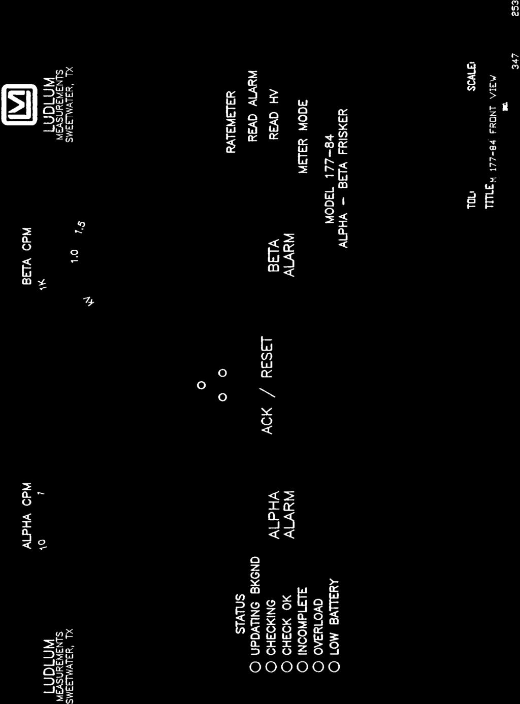
13 Section 3 Description of Controls and Functions Front Panel METERS: The left meter is a three-decade log scale that shows the number of alpha counts. The right meter is a three-decade log scale that shows the number of beta counts. STATUS LEDs: six small LEDs that indicate the status of the instrument. UPDATING BACKGROUND: When this LED is lit, the instrument is updating the background values it will use when subtracting background from a count. Also, when this LED is lit, the instrument is ready for use. When the instrument is first turned on, it will take a mandatory 20-second background count. While it is taking this count, the UPDATING BACKGROUND LED will be flashing. CHECKING: When this LED is lit, the instrument is taking a count. This LED will stay on until the count time has expired or until the switch is opened when count time is set to zero. CHECK OK: This LED will come on after a count has been completed. It will not operate when the count time is set to zero. INCOMPLETE: This LED will come on if the count switch is opened before the count time has expired. It will stay on for 4 seconds or until the switch is closed. OVERLOAD: This LED will come on to indicate that the detector is saturated either by a puncture in the detector face on a scintillation detector, or an exposure to a radiation field above the counting capability of the instrument. The analog meters will deflect full scale when the OVERLOAD LED is illuminated. LOW BATTERY: This LED will come on when the charge on the battery has dropped below the useable range. The voltage level is 5.5 volts measured at the battery terminals. Ludlum Measurements, Inc. Page 5 April 2018
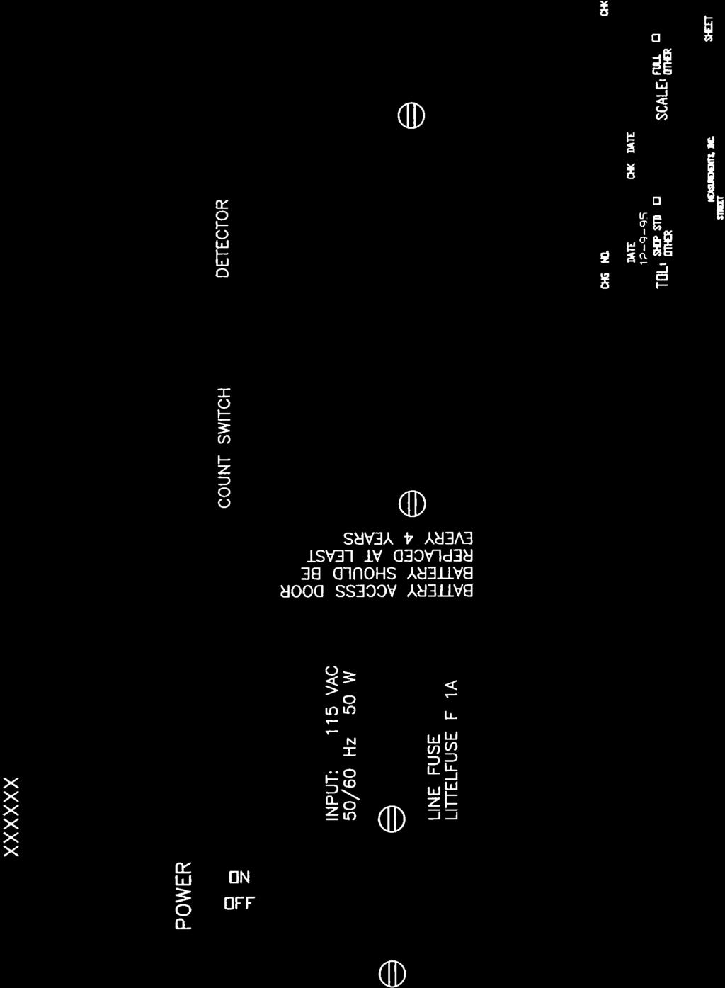
14 ALPHA ALARM: This LED will come on when the alpha radiation level has exceeded the alpha alarm point. BETA ALARM: This LED will come on when the beta radiation level has exceeded the beta alarm point. ACK/RESET: This pushbutton has two functions. If the instrument is in an alarm condition, the first push of the button will turn the audio off. The second push will reset the meters to zero. If there is no alarm, the first push will reset the meters to zero. METER MODE: The METER MODE switch has three functions. In the RATEMETER position, the meters will show incoming counts. In the READ ALARM position, the meters will indicate the alarm setpoints. In the READ HV position, the dual scale beta meter will show the HV setpoint on the kv scale. The alpha meter will go to zero. Rear Panel POWER: This switch turns the instrument ON and OFF. INPUT - LINE FUSE: This is the connector that the cord plugs into to provide power to the instrument. The line fuse is the main fuse for the instrument. To change the fuse, remove the power cord and pry the fuse section out with a screwdriver. BATTERY ACCESS DOOR: The internal rechargeable battery can be accessed by removing this door. The battery should be replaced at least every 4 years. The red wire plugs onto the positive terminal of the battery. COUNT SWITCH: This is a TINI-JAK #41 phone jack. Connect the mating connector to a normally open switch. The switch can then be used to start counts. DETECTOR: This is a coax connector used to connect the instrument to the detector. Internal Controls Remove the instrument cover to access the following controls. AT - Alpha Threshold: This control sets the threshold level for the Alpha channel. It is adjustable from -1 to -180 mv. AAP - Alpha Alarm Point: This control sets the Alpha alarm point. Turn the METER MODE switch to READ ALARM in order to view and set the alarm point. The alarm point can be set from zero to full scale. AMC - Alpha Meter Cal: This control calibrates the Alpha meter. Ludlum Measurements, Inc. Page 6 April 2018
15 BT - Beta Threshold: This control sets the threshold level for the Beta channel. It is adjustable from -1 to -4 mv. BAP - Beta Alarm Point: This control sets the Beta alarm point. Turn the METER MODE switch to READ ALARM to view and set the alarm point. The alarm point can be set from zero to full scale. BMC - Beta Meter Cal: This control calibrates the Beta meter. BW - Beta Window: This control sets the Beta window level. It is adjustable from 4 to 70 mv. HVR - High Voltage Readout: This control calibrates the high-voltage (kv) scale on the Beta meter. Turn the Meter Mode switch to READ HV to view and calibrate the high voltage readout. HVL - High Voltage Limit: This control sets the maximum allowable high-voltage setting. The maximum setting is approximately 2.2 kv. The maximum reading on the meter dial is 2.0 kv. HVS - High Voltage Setpoint: This control sets the high voltage. Turn the METER MODE switch to READ HV to view and set the high-voltage setpoint. OL - Overload: This control sets the high-voltage current level at which the overload circuit will be triggered. BAT - Battery: This control sets the charge voltage for the battery. This point is typically 6.9 volts measured at the battery terminals. VOL - Volume: This control sets the audio volume. Clicks as well as alarm tones are adjusted by this control. Four-position DIP Switch: Positions 1 and 2 control the audio vide for Beta clicks. Settings and values are listed below: Pos 1 Pos 2 1 On On 10 Off On 100 On Off 1000 Off Off Example: For a setting of 1000, the instrument will give one click for every 1000 counts it registers. Note: The AUDIO divide function only affects the lower frequency beta tones. The higher frequency clicks-per-events will be unaffected by the divide-by selection. Ludlum Measurements, Inc. Page 7 April 2018
16 Position 3: This position puts the instrument into meter calibration mode. When the third switch is turned on, the meters will be driven to full scale. You can then use the meter cal controls (AMC and BMC) to adjust the meters to read full scale. Position 4: This position selects whether the alarms are latching or nonlatching. When this switch is on, the alarms are latching. When it is set to latching, the alarm will stay on for 4 seconds after the count time is expired. When in non-latching, the alarm will go off as soon as the radiation level goes back below the alarm point. 16 Position Rotary Switch: This control sets the duration of the counting period in multiples of 8 seconds. When set to zero, the instrument will continue to count as long as the count switch is closed. The duration of the counting period for different settings is listed below: Setting Duration 0 until switch opened 1 8 seconds 2 16 seconds 3 24 seconds 4 32 seconds... E 112 seconds F 120 seconds Ludlum Measurements, Inc. Page 8 April 2018
17 Section 4 Safety Considerations and Maintenance Environmental Conditions for Normal Use Indoor use only No maximum altitude Temperature range of -20 to 50 C (-4 to 122 F) Maximum relative humidity of less than 95% (non-condensing) Mains supply voltage range Vac Maximum transient voltage of 1500 Vac Installation Category (Overvoltage Category) II (as defined by IEC ) Pollution Degree 2 (as defined by IEC 644) (Normally only nonconductive pollution occurs. Temporary conductivity caused by condensation is to be expected.) Cleaning Instructions and Precautions The Model may be cleaned externally with a damp cloth, using only water as the wetting agent. Do not immerse the instrument in any liquid. In addition, the operator is strongly cautioned to avoid contact with internal hazardous live parts that are accessible using a tool. Observe the following precautions when cleaning 1. Turn the instrument OFF and disconnect the instrument power cord. 2. Allow the instrument to sit for one minute before cleaning. Ludlum Measurements, Inc. Page 9 April 2018
18 Caution! Verify instrument voltage input rating before connecting to a power converter. If the wrong power converter is used, the instrument and/or power converter could be damaged. Caution! The operator or responsible body is cautioned that the protection provided by the equipment may be impaired if the equipment is used in a manner not specified by Ludlum Measurements, Inc. Replacement of Fuses Warning! For continued protection against risk of fire, replace only with fuses of the specified type and current rating! Maintenance Instrument maintenance consists of keeping the instrument clean, replacing the battery when necessary, and periodically checking the calibration. An instrument operational check should be performed at least daily by exposing the detector to a known source and confirming the proper reading on the instrument. Re-calibration should be accomplished after any maintenance or adjustment of any kind has been performed on the instrument. Ludlum Measurements recommends recalibration at intervals no greater than one year. Check the appropriate regulatory agencies regulations to determine required recalibration intervals. Instrument Return for Repair/Calibration To return an instrument for repair or calibration, provide sufficient packing material to prevent damage during shipment. Every returned instrument must be accompanied by an Instrument Return Form, which can be downloaded from the Ludlum website at Ludlum Measurements, Inc. Page 10 April 2018
19 Find the form by clicking the Support tab and selecting Repair and Calibration from the drop-down menu. Then choose the appropriate Repair and Calibration division where you will find a link to the form. Battery Replacement The battery should be replaced at least every four years. To replace the battery, remove the two screws holding the battery access door on the rear of the instrument and remove the door. Slide the battery out and unplug the wires from the terminals. Attach wires to the new battery (red wire goes to the positive terminal) and slide back into place. Replace the door. Electrical Safety Precautions Warning! Ignoring the following warnings could result in a potentially hazardous situation, which if mishandled, could result in death or serious personal injury. Do not expose the unit to rain or an environment where it may be splashed by water or other liquids, as doing so may result in fire or electric shock. Use the unit only with the voltage specified of the unit. Using a voltage higher than that which is specified, may result in fire or electric shock. Do not cut, kink, or otherwise damage or modify the power supply cord. In addition, avoid using the power cord in proximity to a heater, and never place heavy objects including the unit itself on the power cord, as doing so may result in fire or electric shock. Avoid installing or mounting the unit or its power supply in unstable locations, such as on a rickety table or a slanted surface. Doing so may result in the unit falling down and causing personal injury or property damage. Ludlum Measurements, Inc. Page 11 April 2018
20 Section 5 Operating Procedures Remove the cover of the Model and set the alarm points, audio volume, beta audio divide, and the count time as desired. Replace the cover. Connect a detector to the Model The detector operating parameters are established by adjusting the detector operating voltage (HV), alpha threshold, and beta window to find an optimum efficiency for the alpha/beta scintillator or proportional detector. The threshold and window parameters can be adjusted to optimize alpha/beta count discrimination, count efficiency, and minimize "cross talk" between channels. Refer to the specific detector Operation Manual or calibration certificate for the suggested threshold and window settings. Once the thresholds and window settings are established, an operating voltageversus-count-rate plot should be performed for both alpha and beta count channels with alpha and beta particle emission sources. The following procedure is an example of determining an operating voltage, threshold, and window settings for an alpha/beta scintillation or proportional detector: Connect a Ludlum Model 500 Pulser or equivalent to the Model While the Model is in the Updating Background mode, adjust the beta threshold (BT) for 2.0 mv and the window (BW) for 50 mv. The pulser counts should be detected on the beta meter above 2.0 ±1 mv and should shut off above 50mV. Adjust the pulser for a 75 mv pulse output and vary the AT control until counts are detected on the alpha meter. Switch the Meter Mode switch to Read HV and adjust the HVS potentiometer for 0.4 to 0.5 kv on the kv scale. Connect the detector to the instrument. Switch Meter Mode back to Ratemeter. Place an alpha source on the detector face. Slowly increase the HVS potentiometer to observe the beta meter for an Ludlum Measurements, Inc. Page 12 April 2018
21 increase, then decrease, and increase again in count as the HV is increased. Decrease the HV until the ratemeter is in the "dip" of the observed count rate-versus-hv plot just performed. Switch to Read HV and note the HV setting. Plot an HV-versus-count rate plateau in 25 volt increments, 50 volts each side of the HV reading found in the above step (i.e., HV setting for count "dip" in the above step = 675 volts; start the plot at 625 volts and increase in 25 volts steps until 725 volts is reached). Plot alpha source, beta source, and background counts for both the alpha and beta channels. Find the optimum operating voltage from the plot, which gives the greatest alpha and beta source efficiency while maintaining no greater than the maximum acceptable level of "cross talk" between channels. Proceed to use instrument. Theory of Operation Refer to schematic series 347, sheet 600 for the following: Detector Input/Amplifier Negative going detector pulses are coupled from the detector through C032 to Amplifier U031. R032 and CR031 protect the input of U031 from inadvertent shorts. Self-biased amplifier U031 provides gain in proportion to R031 divided by R032. Transistor pins 4, 5, and 6 of U031 provide amplification. Pins 12 and 15 of U031 are coupled as a constant current source to pin 6 of U031. The output self-biases to 2Vbe (approximately 1.4 volts) at pin 7 of U031. This provides just enough bias current through pin 6 of U031 to conduct all of the current for the constant current source. Positive pulses from pin 7 of U031 are coupled to the discriminators through R021 and C021. Alpha/Beta Discriminator Positive pulses from amplifier U031 are coupled to comparator U022, pin 6, for alpha discrimination and pins 6 and 2 of U021 for beta discrimination. R001, Alpha Threshold, provides the reference voltage for alpha comparator U022. R103, Beta Threshold (defined as the lower threshold limit of the beta counting window) provides the reference voltage for beta threshold comparator pins 1, 2, and 3 of U021. R202, Beta Window (defined as the upper threshold limit of the beta counting window) provides the reference voltage for the beta window comparator pins 5, 6, and 7 of U021. Ludlum Measurements, Inc. Page 13 April 2018
22 Alpha/Beta Discriminator Logic Circuit Alpha pulses from U022 are coupled to univibrator U121. Pulses at pin 6 of U121 are inverted by Q121 for connection to reset (R) pins 3, 13 of U111. Pin 9 of U121 provides the pulses to be counted by the microprocessor (µp). Pulses from pin 9 of U121 are connected to pin 3 of Ul2l to provide a time delay for the µp clock cycle to complete before the next alpha pulse can be recognized by the µp. Beta pulses from pin 1 of U021 are coupled to univibrator U111. Pulses are coupled to the µp from pin 7 of U111 as long as pins 3 and 13 of U111 remain high (+5V). When an alpha and/or a beta window pulse is present, the reset (pins 3 and 13 of U111) function is enabled and 7 of U111 remains high. Pin 7 of U111 is connected to pin 13 of U111 to provide a time delay for the µp clock cycle to complete before the next beta pulse can be recognized by the µp. Low Voltage Supply Supply Voltage is supplied by the linear regulator VR421 and associated components to provide +5V to power op-amps and logic circuitry. U011 and related components provide +2.5 V reference HVS and Alpha/Beta discriminator controls. U521 regulates the trickle charge to the battery. High Voltage Supply High voltage is developed by blocking oscillator Q431, T331, C422, and rectified by voltage multiplier CR231-CR235, C231-C233, C221, and C133. High voltage increases as current through Q431 increases, with maximum output voltage with Q431 saturated. High voltage is coupled back through R321 to op-amp pin 2 of U321. Resistor network R completes the HV division circuit to ground. R302 provides HV limit at 2.0 kv when the HVS control is at maximum. The regulated HV output is controlled by HVS potentiometer R304. This control provides the reference for comparator pin 3, U321. During stable operation, the voltage at pin 2 of U321 will equal the voltage at pin 3 of U321. Pin 1 of U321 will cause conduction of Q321 to increase or decrease until the HV finds a level of stability. R204, HVR, calibrates the analog meter to the HV output when the METER MODE switch is in the READ HV position. Detector Overload A voltage drop is developed across R131 and sensed by comparator U022 as detector current increases. When the voltage at pin 3 of U022 goes below pin 2, pin 1 goes low, illuminating the OVERLOAD LED and driving the Ludlum Measurements, Inc. Page 14 April 2018
23 meter to full scale. R305, OL, provide adjustment for the overload set point. Meter Drive Pulses are coupled to the gate of Q201 and Q301. R403 and C401 provides integration. Integrated meter drive voltage is coupled via the METER MODE switch to U212. The meter is driven by the emitter of Q211 and Q311, coupled as a voltage follower in conjunction with U212. R101 (AMC) and R201 (BMC) are adjusted to calibrate the ratemeter reading, corresponding to the incoming count rate. R312, R313, R215, and R216 provide temperature compensation for changes in the meter resistance due to temperature variations. Microprocessor U411, Intel N87C51FA, controls all of the data, control inputs, and display information. The clock frequency is crystal controlled by Y311 and related components at MHz. The µp incorporates internal memory (ROM), storing the program information. C423 resets the µp at power-up to initiate the start of the program routine. During the program loop the µp looks at all of the input switches for initiation or status changes and responds accordingly. The µp uses pulse-width modulation to control the analog ratemeter. The analog outputs, ALPHA RATE and BETA RATE, are divided into 255 increments in a 166 µs period. At full meter deflection the low pulse period, leading edge to leading edge, will be 166 µs, 500 cpm = 130 µs, 400 cpm = 104 µs, 200 cpm = 52 µs, 100 cpm = 26 µs, and 0 = no pulse or +5 V. Audio Alpha and/or beta audio pulse frequency is generated by the µp and coupled to Q501. Q501 then inverts the pulses and drives the negative side of the speaker. Bias voltage is provided by the volume control, R402. Ludlum Measurements, Inc. Page 15 April 2018


24 Section 6 Recycling Ludlum Measurements, Inc. supports the recycling of the electronics products it produces for the purpose of protecting the environment and to comply with all regional, national, and international agencies that promote economically and environmentally sustainable recycling systems. To this end, Ludlum Measurements, Inc. strives to supply the consumer of its goods with information regarding reuse and recycling of the many different types of materials used in its products. With many different agencies public and private involved in this pursuit, it becomes evident that a myriad of methods can be used in the process of recycling. Therefore, Ludlum Measurements, Inc. does not suggest one particular method over another, but simply desires to inform its consumers of the range of recyclable materials present in its products, so that the user will have flexibility in following all local and federal laws. The following types of recyclable materials are present in Ludlum Measurements, Inc. electronics products, and should be recycled separately. The list is not all-inclusive. Nor does it suggest that all materials are present in each piece of equipment: Batteries Glass Aluminum and Stainless Steel Circuit Boards Plastics Liquid Crystal Display (LCD) Ludlum Measurements, Inc. products, which have been placed on the market after August 13, 2005, have been labeled with a symbol recognized internationally as the crossed-out wheelie bin. This notifies the consumer that the product is not to be mixed with unsorted municipal waste when discarding; each material must be separated. The symbol will be placed near the AC receptacle, except for portable equipment where it will be placed on the battery lid. Ludlum Measurements, Inc. Page 16 April 2018
25 Section 7 Parts List Model Alpha/Beta Ratemeter Reference Description Part Number UNIT Completely Assembled Model Alpha/Beta Ratemeter Main Board, Drawing 347 x 600 CAPACITORS BOARD Assembled Board C pF, 100V C012 47pF, 100V C UF, 50V C UF, 100v C UF, 50V C UF, 50V C025-C UF, 100V C UF, 20V C pf, 100V C PF, 3KV C111-C123 47PF, 100V C131-C MF, 3KV C UF, 50V C UF, 50V C UF, 50V C MF, 3KV C UF, 50V C231-C MF, 3KV C UF, 50V C UF, 50V C313-C PF, 100V C UF, 50V C322 1 UF, 35V C UF, 50V C422 1 UF, 35V C UF, 20V C424-C UF, 6.3V C MF, 35V C511 47MF, 10V Ludlum Measurements, Inc. Page 17 April 2018
26 Reference Description Part Number DIODES CR031 MMBD7000LT CR121 MMBD914L CR122 MMBD914L CR231 GI CR232 GI CR233 GI CR234 G CR235 G CR421 MMBD914L CR521-CR532 CXSH TRANSISTORS RESISTORS Q121-Q201 2N7002L Q211 MMBT3904T Q301 2N7002L Q311 MMBT3904T Q321 MMBT3904T Q431 MJD Q501 2N7002L Q521 MJD R001 1 MEG TRIMMER R K TRIMMER R K 1/8W 1% R012 10K 1/8W 1% R OHM 1/8W 1% R K 1/8W 1% R023 10K 1/8W 1% R K 1/8W 1% R025 10K 1/8W 1% R K 1/8W 1% R032 10K 1/8W 1% R K 1/8W 1% R034 10K 1/8W 1% R K 1/8W 1% R K 1/8W 1% R037 1 MEG 1/4W 5% R101 5K TRIMMER R K 1/8W 1% R103 10K TRIMMER R K TRIMMER R K 1/8W 1% R K 1/8W 1% R OHM 1/8W 1% R K 1/8W 1% Ludlum Measurements, Inc. Page 18 April 2018
27 Reference Description Part Number R K 1/8W 1% R K 1/8W 1% R MEG 1/4W 5% R132 1 GIG-OHM FHV-1 2% R133 1 MEG 1/4W 5% CR R134 1 GIG-OHM FHV-1 2% R201 5K TRIMMER R202 1 MEG TRIMMER R K 1/8W 1% R204 1 MEG TRIMMER R K 1/8W 1% R212 10K 1/8W 1% R K 1/8W 1% R214 1M 1/8W 1% R G R OHM 1/8W 1% R217 1K 1/8W 1% R218 10K 1/8W 1% R219 10K 1/8W 1% R301 1M 1/8W 1% R302 1 MEG TRIMMER R303 1M 1/8W 1% R K TRIMMER R305 1 MEG TRIMMER R311 10K 1/8W 1% R OHM 1/8W 1% R G R314 1K 1/8W 1% R315 1M 1/8W 1% R K 1/8W 1% R317 10K 1/8W 1% R K 1/8W 1% R321 1M 1/8W 1% R K 1/8W 1% R401 1 MEG TRIMMER R402 5KTRIMMER R K 1/8W 1% R OHM 1/8W 1% R501 10K 1/8W 1% R K 1/8W 1% R K 1/8W 1% R K 1/8W 1% R522 1K 1/8W 1% R K 1/8W 1% R OHM 1/8W 5% Ludlum Measurements, Inc. Page 19 April 2018
28 Reference Description Part Number NETWORK TRANSFORMERS SWITCHES INTEGRATED CIRCUITS RN K T331 XFMR-L T501 XFMR-Model 177 AUDIO S401 90HBW04S S501 NC3KR16B U011 LM285M U021 TLC372ID U022 TLC372ID U031 CA3096M U111 CD74HC4538M U121 CD74HC4538M U211 TLC372ID U212 IC- TLC27M7ID U321 IC- TLC27M7ID U411 IC- N87C51FA Socket U511 IC- TLC372ID U521 IC- ICL7663SCBA VOLTAGE REGULATOR VR421 LT1129CQ CRYSTALS Y MHZ Front Panel Board, Drawing 347 x 244 BOARD Assembled Board CAPACITORS C µF, 35V LEDS DS113 LED-E DS114 LED-E DS115 LED-E DS116 LED-E DS117 LED-E DS118 LED-E DS119 LED-E176 RED DS120 LED-E176 RED Ludlum Measurements, Inc. Page 20 April 2018
29 RESISTORS R OHM 1/4W 5% R OHM 1/4W 5% SWITCHES NETWORK INTEGRATED CIRCUITS S ELEMENT U OHM, 16P U125 SN75512BN Chassis Wiring Diagram, Drawing 347 x 243 Reference Description Part Number AUDIO DS1 TEC-3526-PU CONNECTORS SWITCHES J1 CONN MTA 100 J2 CONN MTA100 J3 CONN MTA100 J4 CONN MTA-100 J5-J6 CONN J8 SERIES C UG706/U J9 TINI-JAK # S1 Power S2 Meter Mode MISCELLANEOUS M1 METER ASSY Model * MAIN BOARD MODEL * FRONT PANEL BOARD Model * FRONT CHASSIS HARNESS Model * REAR CHASSIS HARNESS MODEL B1 BATTERY NP1-6 YUASA F1 FUSE 1 AMP 5X20mm T1 TRANSFORMER Ludlum Measurements, Inc. Page 21 April 2018
30 Section 8 Appendix Appendix 1: Checkout Procedure 1. Check all connections. Install the microprocessor chip 87C51FC with program firmware #34700N00 (or greater), and turn instrument ON with battery disconnected and the red positive lead to the battery attached to a +6 Vdc power supply. Check for +5 V at pin 1 of the LT1129CQ-5 regulator and +2.5 Vdc at pin 8 of the LM V. The current measured from the power supply should be less than 40 ma (peaking at 60 ma with the LEDs on). The LOW BATTERY LED should turn ON whenever the battery voltage is at or below 5.5 Vdc. Turn instrument OFF. 2. Disconnect the power supply. Attach the 120 Vac power cord and turn the instrument ON. The DC input voltage at pin 5 of the LT129CQ-5 from the transformer should be approximately 9.5 Vdc within 1.5 Vdc. Rotate the pot labeled BAT until the voltage at the positive lead to the battery is 6.9 Vdc. Turn instrument OFF. 3. With the instrument in an upright position, zero both meters using the zero adjust screw at the lower front of each meter. Set the dipswitch #3 (CALIBRATE) to ON. Turn the METER MODE switch to the RATEMETER position. Move the OPERATE MODE switch to the OPERATE position. 4. Turn the instrument ON. The power-on test by the microprossor should light all the front-panel LEDs and briefly drive both meters full scale. In CALIBRATE mode, both meters should then be driven full scale. Adjust the pot labeled AMC (Alpha Meter Cal) until the alpha meter is full scale. Adjust the pot labeled BMC ( Beta Meter Cal) until the beta meter is full scale. Turn the instrument OFF, and move dipswitch #3 to the OFF position. 5. Connect the instrument to a Ludlum Model 500 pulser set at 60 mv pulse height and 100 cpm. Rotate the pots labeled AAP (Alpha Alarm Point), BAP (Beta Alarm Point), and OL (OverLoad) fully clockwise. Rotate the VOL (audio Volume) pot fully clockwise, then turn back two full turns. Turn the instrument ON. Adjust the HVS ( High Voltage Set) pot and the HVL (High Voltage Limit) pot until the high voltage read by the Model 500 is about 2300 Vdc within 200 Vdc. Check that Ludlum Measurements, Inc. Page 22 April 2018
31 there are no shorts present in the HV section or in the coax connection to the detector connector. Set the high voltage to 1750 Vdc. Turn the METER MODE switch to READ HV. Adjust the HVR (High Voltage Read) until the beta meter reads 1.75 kv. Turn the METER MODE switch back to RATEMETER Mode. 6. Adjust the AT (Alpha Threshold) pot until the instrument reads 100 cpm with the incoming 60 mv pulsed. Change the Model 500 to output 2.5 mv pulses at 10,000 cpm. Adjust the BT (Beta Threshold) until the beta meter shows 10K cpm. Set the Model 500 to 25 mv pulse height and adjust the BW (Beta Window) pot so that beta pulses are counted between 2/5 mv and 25 mv. The complete adjustment ranges are: Alpha Threshold (AT) from approximately 3 mv to 180 mv Beta Threshold (BT) from approximately 0.5 mv to 4 mv Beta Window (BW) from approximately 4 mv to 70 mv 7. Turn the METER MODE switch to the READ ALARM position. Adjust the AAP pot fully counterclockwise and fully clockwise. Ascertain that the alpha meter extends from 0 to full scale. Set the alarm to two-thirds scale. Repeat this process for the BAP pot and the beta alarm. Turn the METER MODE switch back to the RATEMETER setting. 8. Rotate the pot OL counterclockwise until you reach a point where the Overload LED turns on and both meters go full scale. Rotate the OL pot back clockwise for one full turn. 9. Set the internal rotary count switch to 0. Set the dip switch to: 1=OFF 2=ON------beta divide by 10 3=OFF-----no cal mode 4=ON------batching alarm mode 10. Use a shorted plug or a count switch plugged into the back of the instrument at the jack labeled COUNT SWITCH to start/stop frisking. Verify that during counting the audio turns ON and the COUNTING light turns ON. The meters should also subtract out the background while counting. Input 10 kcpm beta pulses and toggle dip switches #1 and #2 to see that the beta divide-by can be set to 1, 10, 100, or Return the dip switches #1 and #2 to OFF, ON. 11. Cause an alarm by COUNTING and increasing the input pulse rate. Verify that the latching alarm mode retains the alarm after the meter decreases below the alarm point. Verify that the ACK/RESET quiets the alarm audio with the first press, the clears the alarm LED with the second press. Switch dipswitch #4 to OFF to put the instrument into non-latching alarm mode and verify that the alarm is non-latching. Ludlum Measurements, Inc. Page 23 April 2018
32 12. Set the internal rotary count switch to 1. Start COUNTING. The CHECK OK should turn ON after 8 seconds and a double-beep should sound. Start COUNTING again, but let off of the count switch before the 8 seconds is up, and see if the INCOMPLETE LED turns ON with a low triple-beep. Set the internal count switch to 2 (16 seconds) and then F (120 seconds) and verify the count times with a stop watch. Reset the rotary count switch to Burn the instrument in overnight and recheck the +5 Vdc, +2.5 Vdc, and the 1750 Vdc. Appendix 2: Model Mode Switch Addition The Mode Switch addition on the Model allows the user to switch the instrument between the Frisk Mode and the Operate Mode. In the Frisk Mode, the count switch is held closed until the instrument is switched back to the Operate Mode. This allows the user to use the detector continuously without having to hold the count switch closed at the same time. In the Operate Mode, whatever count switch is attached to the instrument will be closed as long as the switch is held down. This addition was originally put on the Model so that it would work better with the Model 4902 Hand & Foot Detector Stand. The user can put the Model into Frisk Mode and then remove the hand detector from its cradle and use it as a frisker. Without this addition, the user would have been required to hold his foot on the foot detector of the Model 4902 the entire time that he was frisking with the hand detector. The foot detector of the Model 4902 actuates the count switch. Electronically, the only change is that a toggle switch is wired in parallel with the Count Switch connector on the rear of the instrument. Mechanically, the toggle switch and a silk-screened plate is mounted on the rear of the instrument. Mechanically, the toggle switch and a silkscreened plate is mounted on the front of the instrument. The part number for the Mode Switch Addition is Ludlum Measurements, Inc. Page 24 April 2018
33 Appendix 3: Model 4902 Specifications The Model 4902 is a stand that holds two gas proportional detectors, one upper detector and one lower detector. The upper detector sets in position to be used as a hand detector, or it can be removed and used as a frisker. The foot detector has a switch mounted underneath so that count timer is started when the detector is pushed down. There are no counting electronics included with the Model If a count timer is required, the instrument used with the Model 4902 must have that capability. An instrument typically used with the Model 4902 is a Ludlum Model Other instruments can be used. Specifications Upper Detector: Lower Detector: Background: Gas Flow: Count Switch: Instrument Power: 200 cm 2 active area 79% open screen, cm (0.030 in.) thick Efficiencies (4π): 20% for 90 Sr; 28% for 99 Tc; and 13% for 239 Pu Attached with 1.8 m (6 ft) cable Approximately 520 cm 2 active area 63% open screen, 0.26 cm (0.104 in.) thick Efficiencies (4π) 9% for 90 Sr; 14% for 99 Tc; and 4% for 239 Pu With both detectors connected, < 10 cpm alpha, approximately 1000 cpm beta Bubbler indicator, typically 10 cc/min or less consumption Supply connector: Colder Products PMC Normally open, TINI_JAK #41 phone plug as connector. Actuated by stepping on foot detector. 115 Vac outlet with a 1 A fuse Ludlum Measurements, Inc. Page 25 April 2018
34 Section 9 Diagrams and Drawings Main Board, Drawing 347 x 600 (3 sheets) Main Board Component Layout, Drawing 347 x 243A (2 sheets) Front Panel Board, Drawing 347 x 244 Front Panel Board Component Layout, Drawing 347 x 258A (2 sheets) Wiring Diagram, Drawing 347 x 243 Ludlum Measurements, Inc. Page 26 April 2018
35
36
37
38
39
40
41
42
43
LUDLUM MODEL 44-2 GAMMA SCINTILLATOR. February 2018 Serial Number PR and Succeeding Serial Numbers
 LUDLUM MODEL 44-2 GAMMA SCINTILLATOR February 2018 Serial Number PR361009 and Succeeding Serial Numbers LUDLUM MODEL 44-2 GAMMA SCINTILLATOR February 2018 Serial Number PR361009 and Succeeding Serial
LUDLUM MODEL ALPHA, BETA, GAMMA HAND DETECTOR. June 2016 Serial Number and Succeeding Serial Numbers
 LUDLUM MODEL 44-25 ALPHA, BETA, GAMMA HAND DETECTOR June 2016 Serial Number 155835 and Succeeding Serial Numbers LUDLUM MODEL 44-25 ALPHA, BETA, GAMMA HAND DETECTOR June 2016 Serial Number 155835 and
LUDLUM MODEL 44-3 LOW ENERGY GAMMA SCINTILLATOR. May 2018 Serial Number PR and Succeeding Serial Numbers
 LUDLUM MODEL 44-3 LOW ENERGY GAMMA SCINTILLATOR May 2018 Serial Number PR134823 and Succeeding Serial Numbers LUDLUM MODEL 44-3 LOW ENERGY GAMMA SCINTILLATOR May 2018 Serial Number PR134823 and Succeeding
LUDLUM MODEL AND LUDLUM MODEL ALPHA, BETA, & GAMMA DETECTORS
 LUDLUM MODEL 44-9-18 AND LUDLUM MODEL 44-9-19 ALPHA, BETA, & GAMMA DETECTORS January 2018 Serial Number PR254331 and Succeeding Serial Numbers LUDLUM MODEL 44-9-18 AND LUDLUM MODEL 44-9-19 ALPHA, BETA,
LUDLUM MODEL ALARM RATEMETER. June 2017 Serial Number and Succeeding Serial Numbers
 LUDLUM MODEL 177-61 ALARM RATEMETER June 2017 Serial Number 101825 and Succeeding Serial Numbers LUDLUM MODEL 177-61 ALARM RATEMETER June 2017 Serial Number 101825 and Succeeding Serial Numbers STATEMENT
LUDLUM MODEL 19A. Micro R Meter. May 2017 Serial No and Succeeding Serial Numbers
 LUDLUM MODEL 19A Micro R Meter May 2017 Serial No. 144020 and Succeeding Serial Numbers LUDLUM MODEL 19A Micro R Meter May 2017 Serial No. 144020 and Succeeding Serial Numbers Model 19A Micro R Meter
MODEL AND MODEL GAS PROPORTIONAL DETECTORS. December 2016 Serial No and Succeeding Serial Numbers
 MODEL 43-37 AND MODEL 43-37-1 GAS PROPORTIONAL DETECTORS Serial No. 086152 and Succeeding Serial Numbers MODEL 43-37 AND MODEL 43-37-1 GAS PROPORTIONAL DETECTORS Serial No. 086152 and Succeeding Serial
LUDLUM MODEL 25 AND 25-1 PERSONAL RADIATION MONITOR USER S MANUAL. October 2014 Serial Number and Succeeding Serial Numbers
 LUDLUM MODEL 25 AND 25-1 PERSONAL RADIATION MONITOR USER S MANUAL October 2014 Serial Number 25000100 and Succeeding Serial Numbers LUDLUM MODEL 25 AND 25-1 PERSONAL RADIATION MONITOR USER S MANUAL October
LUDLUM MODEL and PANCAKE CLUSTER DETECTORS. June 2016
 LUDLUM MODEL 44-89 and 44-94 PANCAKE CLUSTER DETECTORS June 2016 LUDLUM MODEL 44-89 and 44-94 PANCAKE CLUSTER DETECTORS June 2016 STATEMENT OF WARRANTY Ludlum Measurements, Inc. warrants the products covered
LUDLUM MODEL 44-7 Alpha, Beta, Gamma Detector. July 2012 Serial No. PR and succeeding Serial Numbers
 LUDLUM MODEL 44-7 Alpha, Beta, Gamma Detector July 2012 Serial No. PR090405 and succeeding Serial Numbers LUDLUM MODEL 44-7 Alpha, Beta, Gamma Detector July 2012 Serial No. PR090405 and succeeding Serial
LUDLUM MODEL 52 PORTABLE PORTAL MONITOR. November 2011 Serial No and Succeeding Serial Numbers
 LUDLUM MODEL 52 PORTABLE PORTAL MONITOR Serial No. 175872 and Succeeding Serial Numbers LUDLUM MODEL 52 PORTABLE PORTAL MONITOR Serial No. 175872 and Succeeding Serial Numbers TABLE OF CONTENTS 1. GENERAL...
MODEL 23 AND 23-1 ELECTRONIC PERSONAL DOSIMETER. August 2017
 MODEL 23 AND 23-1 ELECTRONIC PERSONAL DOSIMETER August 2017 MODEL 23 AND 23-1 ELECTRONIC PERSONAL DOSIMETER August 2017 ii STATEMENT OF WARRANTY Ludlum Measurements, Inc. warrants the products covered
LUDLUM MODEL 26 FRISKER USER S MANUAL. December 2016 Serial Number PF and Succeeding Serial Numbers
 LUDLUM MODEL 26 FRISKER USER S MANUAL December 2016 Serial Number PF001075 and Succeeding Serial Numbers LUDLUM MODEL 26 FRISKER USER S MANUAL December 2016 Serial Number PF001075 and Succeeding Serial
LUDLUM MODEL 2360 SCALER/RATEMETER DATA LOGGER. July 2016 Serial Number and Succeeding Serial Numbers
 LUDLUM MODEL 2360 SCALER/RATEMETER DATA LOGGER July 2016 Serial Number 133669 and Succeeding Serial Numbers LUDLUM MODEL 2360 SCALER/RATEMETER DATA LOGGER July 2016 Serial Number 133669 and Succeeding
LUDLUM MODEL 44-9 ALPHA, BETA, GAMMA DETECTOR. February 2010 Serial Number PR and Succeeding Serial Numbers
 LUDLUM MODEL 44-9 ALPHA, BETA, GAMMA DETECTOR February 2010 Serial Number PR090405 and Succeeding Serial Numbers LUDLUM MODEL 44-9 ALPHA, BETA, GAMMA DETECTOR February 2010 Serial Number PR090405 and
LUDLUM MODEL DIGITAL RADIATION MONITOR WITH INTERNAL SCINTILLATOR. August 2010 Serial Number and Succeeding Serial Numbers
 LUDLUM MODEL 375-600 DIGITAL RADIATION MONITOR WITH INTERNAL SCINTILLATOR August 2010 Serial Number 179939 and Succeeding Serial Numbers 1 LUDLUM MODEL 375-600 DIGITAL RADIATION MONITOR WITH INTERNAL SCINTILLATOR
LUDLUM MODEL 26-1 FRISKER USER S MANUAL. April 2017 Serial Number PF and Succeeding Serial Numbers
 LUDLUM MODEL 26-1 FRISKER USER S MANUAL April 2017 Serial Number PF002366 and Succeeding Serial Numbers LUDLUM MODEL 26-1 FRISKER USER S MANUAL April 2017 Serial Number PF002366 and Succeeding Serial Numbers
MODEL RWM RADIATION WASTE MONITOR LUDLUM MODEL RWM RADIATION WASTE MONITOR INSTALLATION MANUAL
 LUDLUM MODEL 3500-1000RWM RADIATION WASTE MONITOR INSTALLATION MANUAL August 2001 1 RECEIVING CONDITION EXAMINATION Be sure to verify that the shipping carton is received in good condition with no visible
LUDLUM MODEL 3276 SERIES FRISKER/AREA MONITOR USER S MANUAL. November 2017 Serial Number: and Succeeding Firmware: 49830n30 and Higher
 LUDLUM MODEL 3276 SERIES FRISKER/AREA MONITOR USER S MANUAL November 2017 Serial Number: 25009185 and Succeeding Firmware: 49830n30 and Higher LUDLUM MODEL 3276 SERIES FRISKER/AREA MONITOR USER S MANUAL
Model OEM-2 INSTRUCTIONS FOR USE
 ECO SENSORS, INC. 3-03.2 OEM OZONE CONTROLLER Model OEM-2 INSTRUCTIONS FOR USE GENERAL The model OEM-2 is a system to control ozone generators and alarms based on an adjustable ozone concentration set
Victoreen Primalert 35 Area Radiation Monitor
 Victoreen 05-437 Primalert 35 Area Radiation Monitor Operators Manual March 2005 Manual No. 126011 Rev. 3 2003, 2005 Fluke Corporation, All rights reserved. Printed in U.S.A. All product names are trademarks
LUDLUM MODEL 35 SERIES DIGITAL SURVEY METER USER S MANUAL
 LUDLUM MODEL 35 SERIES DIGITAL SURVEY METER USER S MANUAL September 2016 LUDLUM MODEL 35 SERIES DIGITAL SURVEY METER USER S MANUAL September 2016 STATEMENT OF WARRANTY Ludlum Measurements, Inc. warrants
LUDLUM MODELS 375 (INCLUDING SERIES ONE), 375/1, 375/2 AND 375/4 DIGITAL WALL-MOUNT AREA MONITORS
, 375/1, 375/2 AND 375/4 DIGITAL WALL-MOUNT AREA MONITORS") LUDLUM MODELS 375 (INCLUDING SERIES ONE), 375/1, 375/2 AND 375/4 DIGITAL WALL-MOUNT AREA MONITORS April 2018 Serial Number 278020 and Succeeding Serial Numbers LUDLUM MODELS 375 (INCLUDING SERIES ONE),
LUDLUM MODELS 375 (INCLUDING SERIES ONE), 375/1, 375/2 AND 375/4 DIGITAL WALL-MOUNT AREA MONITORS April 2018 Serial Number 278020 and Succeeding Serial Numbers LUDLUM MODELS 375 (INCLUDING SERIES ONE),
Instruction Manual WARNING
 Controllers Instruction Manual WARNING THIS MANAUL MUST BE CAREFULLY READ BY ALL INDIVIDUALS WHO HAVE OR WILL HAVE THE RESPONSIBILITY FOR INSTALLING, USING OR SERVICING THIS PRODUCT. Like any piece of
Beacon 110 Gas Monitor Operator s Manual
 Beacon 110 Gas Monitor Operator s Manual Part Number: 71-0110RK Revision: H Released: 12/5/17 RKI Instruments, Inc. www.rkiinstruments.com Product Warranty RKI Instruments, Inc., warrants gas alarm equipment
GasScanner 1C. Single Channel Monitor. Operator s Manual. MINT-0278-XX Rev A
 GasScanner 1C Single Channel Monitor Operator s Manual MINT-0278-XX Rev A Product Warranty Matheson Tri-Gas, Inc., warrants gas alarm equipment sold by us to be free from defects in materials, workmanship,
Beacon 800 Gas Monitor Operator s Manual
 Beacon 800 Gas Monitor Operator s Manual Part Number: 71-0037RK Revision: F Released: 4/18/17 www.rkiinstruments.com Product Warranty RKI Instruments, Inc. warrants gas alarm equipment sold by us to be
Controllers. Instruction Manual WARNING
 Controllers Instruction Manual WARNING THIS MANUAL MUST BE CAREFULLY READ BY ALL INDIVIDUALS WHO HAVE OR WILL HAVE THE RESPONSIBILITY FOR INSTALLING, USING OR SERVICING THIS PRODUCT. Like any piece of
Beacon 200 Gas Monitor Operator s Manual. Part Number: RK Released: 6/6/08
 Beacon 200 Gas Monitor Operator s Manual Part Number: 71-2102RK Released: 6/6/08 Table of Contents Chapter 1: Introduction.................................................3 Overview.............................................................3
F PC and AO OUTPUT BOARDS INSTRUCTION MANUAL. Blue-White. Industries, Ltd.
 F-2000 PC and AO OUTPUT BOARDS INSTRUCTION MANUAL Blue-White R Industries, Ltd. 500 Business Drive Huntington Beach, CA 92649 USA Phone: 714-89-8529 FAX: 714-894-9492 E mail: sales@blue-white.com or techsupport@blue-white.com
RAM GENE-1 ERK. Contamination & Radiation Meter. Operating Manual. Document #PRIR90N2.DOC Version 2.2 October 2009
 RAM GENE-1 ERK MK-Ι & MK-ΙΙ Contamination & Radiation Meter Operating Manual Document #PRIR90N2.DOC Version 2.2 October 2009 Version / Revision Log: RAM GENE-1 ERK/ Operating Manual Ver./Rev.# Date Revised
RK CO 2 Transmitter Operator s Manual
 65-2397RK CO 2 Transmitter Operator s Manual Part Number: 71-0185RK Revision: B Released: 7/18/14 RKI Instruments, Inc. www.rkiinstruments.com WARNING Read and understand this instruction manual before
Alarm Tone Generator Model AG17
 Alarm Tone Generator Installation & Operation P005089 Rev. C 150930 9/30/2015 12:25 PM Ph: 403.258.3100 \ email:info@guardiantelecom.com \ www.guardiantelecom.com Table of Contents Package Contents...
1040 Gas Monitor INSTALLATION AND OPERATING INSTRUCTIONS AMC-1040 WITH INTEGRAL ELECTROCHEMICAL SENSOR
 1040 Gas Monitor INSTALLATION AND OPERATING INSTRUCTIONS AMC-1040 WITH INTEGRAL ELECTROCHEMICAL SENSOR IMPORTANT: Please read these installation and operating instructions completely and carefully before
Sierra Series 900 Single & Dual Channel System. Instruction Manual
 Series 240/24 Instruction Manual Table of Contents Sierra Series 900 Single & Dual Channel System Instruction Manual Part Number IM-90-07/05 Revision D. 5 Harris Court, Building L Monterey, CA 93940 (83)
RK Hydrogen Sulfide Transmitter Operator s Manual
 65-2331RK Hydrogen Sulfide Transmitter Operator s Manual Part Number: 71-0176RK Revision: B Released: 11/26/14 RKI Instruments, Inc. www.rkiinstruments.com WARNING Read and understand this instruction
INSTALLATION. and INSTRUCTION MANUAL. for QUALITY AIR BREATHING SYSTEMS. Model ABM - 715
 INSTALLATION and INSTRUCTION MANUAL for QUALITY AIR BREATHING SYSTEMS Model ABM - 715 M A R T E C H S E R V I C E S C O M P A N Y P.O. Box 7079 OFFICE: 800-831-1525 Mazeppa, MN 55956 Fax : (507)843-4953
MODEL 8144-RD CLOCK SELECTOR/DISTRIBUTION AMPLIFIER INSTRUCTION MANUAL. SPECTRACOM CORPORATION 95 Methodist Hill Drive, Suite 500 Rochester, NY 14623
 MODEL 8144-RD CLOCK SELECTOR/DISTRIBUTION AMPLIFIER INSTRUCTION MANUAL SPECTRACOM CORPORATION 95 Methodist Hill Drive, Suite 500 Rochester, NY 14623 PHONE 585-321-5800 FAX 585-321-5218 REVISIONS, IF ANY,
RAM GENE / RAM GENE-1
 RAM GENE / RAM GENE-1 Radiation Meters Operating Manual Document #PRIR69N0.DOC Version 6.1 - December 2000 ROTEM INDUSTRIES LTD. ROTEM Industrial Park P.O.Box 9046, Beer-Sheva 84190, ISRAEL Tel: 972-8-6571312/6568652
INSTALLATION. and INSTRUCTION MANUAL. for QUALITY AIR BREATHING SYSTEMS. Model ABM - 700
 INSTALLATION and INSTRUCTION MANUAL for QUALITY AIR BREATHING SYSTEMS Model ABM - 700 M A R T E C H S E R V I C E S C O M P A N Y P.O. Box 7079 OFFICE: 800-831-1525 Mazeppa, MN 55956 Fax : (507)843-4953
STATUS ALARM HISTORY ALARM RESET
 Instruction Manual Model 1582-42L Data Switch February 1999, Rev 0 CH1 AUTO CH2 SWITCH 1 2 1 2 STATUS 1 2 MODEL 1582 SWITCH CROSS TECHNOLOGIES INC. CH1 ONLINE MANUAL SELECT CH2 ONLINE SWITCH RESET MAN
Document No
 CO Guardian LLC 1951 E. Airport Dr. Tucson, AZ 85706 CARBON MONOXIDE DETECTOR MODEL 452 INSTALLATION AND OPERATIONAL MANUAL Document No. 01-2510-02 MODEL 452 INSTALLATION AND OPERATIONAL MANUAL Page 1
AC300WR 300 WATT REDUNDANT HF-20A CHASSIS POWER SUPPLY/SYSTEM MONITOR TECHNICAL MANUAL
 AC300WR 300 WATT REDUNDANT HF-20A CHASSIS POWER SUPPLY/SYSTEM MONITOR TECHNICAL MANUAL October 2003 Revision A Copyright October 2003 VERSITRON, Inc 83 Albe Drive / Suite C Newark, DE 19702 www.versitron.com
MODEL A-316 CARBON MONOXIDE (CO) MONITOR AND ALARM FOR COMPRESSED AIR TESTING
 MONITOR AND ALARM FOR COMPRESSED AIR TESTING") MODEL A-316 CARBON MONOXIDE (CO) MONITOR AND ALARM FOR COMPRESSED AIR TESTING FOR OPERATION FROM 115 AC POWER Andersen Medical Gas 12 Place Lafitte Madisonville, LA 70447 http://www.themedicalgas.com 1-866-288-3783
MODEL A-316 CARBON MONOXIDE (CO) MONITOR AND ALARM FOR COMPRESSED AIR TESTING FOR OPERATION FROM 115 AC POWER Andersen Medical Gas 12 Place Lafitte Madisonville, LA 70447 http://www.themedicalgas.com 1-866-288-3783
CO2 RESPONDER Portable Carbon Dioxide Detector QUICK REFERENCE GUIDE
 CO2 RESPONDER Portable Carbon Dioxide Detector QUICK REFERENCE GUIDE GasAlertMicro 5 IR from Refer to for more details. Manual provided on CD with unit at time of purchase 2 Table of Contents Getting Started.
Automatic Humidity Controller. Model 512 (Revision C) Operating Manual
 Operating Manual") Automatic Humidity Controller Model 512 (Revision C) Operating Manual 6/5/03 1 TABLE OF CONTENTS 1.0 INTRODUCTION 3 2.0 GENERAL DESCRIPTION 3 3 2.1 Humidity Sensor 3 2.2 Control Unit 4 2.3 System Operation
Automatic Humidity Controller Model 512 (Revision C) Operating Manual 6/5/03 1 TABLE OF CONTENTS 1.0 INTRODUCTION 3 2.0 GENERAL DESCRIPTION 3 3 2.1 Humidity Sensor 3 2.2 Control Unit 4 2.3 System Operation
CT-7 Series Toxic Gas Transmitter Operator s Manual
 65-2341 CT-7 Series Toxic Gas Transmitter Operator s Manual Part Number: 71-0424 Revision: P1 Released: 6/8/17 RKI Instruments, Inc. www.rkiinstruments.com WARNING Read and understand this instruction
OPERATING INSTRUCTIONS AND REPLACEMENT PARTS
 OPERATING INSTRUCTIONS AND REPLACEMENT PARTS Models: CO-91 and CO-91ACR WARNING This manual must be read carefully and followed by all persons who have or will have the responsibility for using or servicing
GG-2 2-CHANNEL GAS DETECTION CONTROL PANEL. Installation and Operation Manual
 GG-2 2-CHANNEL GAS DETECTION CONTROL PANEL Installation and Operation Manual 2 GG-2 Warning Use this product only in the manner described in this manual. If the equipment is used in a manner not specified
Interscan Corporation. Instruction Manual Series Compact Portable Analyzer
 Interscan Corporation Instruction Manual 4000 Series Compact Portable Analyzer 1 2 INTERSCAN CORPORATION Simplified 4000 SERIES MANUAL TABLE OF CONTENTS SECTION TITLE PAGE 1.0 Equipment Description 4 2.0
RK-05 Combustible Gas Transmitter Operator s Manual
 65-2405RK-05 Combustible Gas Transmitter Operator s Manual Part Number: 71-0180RK Revision: 0 Released: 2/16/11 RKI Instruments, Inc. www.rkiinstruments.com WARNING Read and understand this instruction
Models NFPA 1221-A, NFPA 1221-B Public Safety DAS Annunciator Panel. Revision E 61117
 Models NFPA 1221-A, NFPA 1221-B Public Safety DAS Annunciator Panel Revision E 61117 CAUTION: (Read This First) This panel has been designed to make it nearly bullet proof to mistakes made when wiring
ProTalk. Expander. Operating Manual Model B1292. July 28, 2009 Rev. 1.01
 ProTalk Expander Operating Manual Model B1292 July 28, 2009 Rev. 1.01 TABLE OF CONTENTS 1. Introduction... 1 2. Installation... 2 2.1 Wiring Diagram... 3 3. Operations... 4 4. Programming (B1225 Mode)...
OVEN INDUSTRIES, INC.
 OVEN INDUSTRIES, INC. OPERATING MANUAL Model 5C7-252 TEMPERATURE CONTROLLER With PLC Inputs Introduction Thank you for purchasing our controller. The Model 5C7-252 is an exceptionally versatile unit and
GasScanner 8C. Eight Channel Monitor. Operator s Manual. MINT-0281-XX Rev. A 01/29/08
 GasScanner 8C Eight Channel Monitor Operator s Manual MINT-0281-XX Rev. A 01/29/08 Product Warranty Matheson Tri-Gas, Inc., warrants gas alarm equipment sold by us to be free from defects in materials,
Warner Instruments, Inc Dixwell Avenue, Hamden, CT (800) / (203) (203) fax
 / (203) (203) fax") TC-324B Manual, Rev. 05.01.31 Single Channel Heater Controller Model TC-324B 1125 Dixwell Avenue, Hamden, CT 06514 (800) 599-4203 / (203) 776-0664 (203) 776-1278 - fax TC-324B Manual, Rev. 05.01.31 TC-324B
TC-324B Manual, Rev. 05.01.31 Single Channel Heater Controller Model TC-324B 1125 Dixwell Avenue, Hamden, CT 06514 (800) 599-4203 / (203) 776-0664 (203) 776-1278 - fax TC-324B Manual, Rev. 05.01.31 TC-324B
ANALOX 5001 Carbon Dioxide Monitor. User Manual ANALOX Analox 5001 Carbon Dioxide Monitor User Manual
 ANALOX 5001 ANALOX 5001 Carbon Dioxide Monitor User Manual Analox Sensor Technology Ltd 15 Ellerbeck Court, Stokesley Business Park North Yorkshire, TS9 5PT T: +44 (0)1642 711400 F: +44 (0)1642 713900
A1UL PERS. Personal Emergency Response System. For Technical Support Please Contact Your Service Provider Or Distributor
 A1UL PERS Personal Emergency Response System TABLE OF CONTENTS 1. READ THIS FIRST... 1 2. SYSTEM OVERVIEW.. 1 3. COMPONENTS 2 4. UNIT OPERATION! Standby Mode.. 3! Emergency Activation. 3! Answering Incoming
GASGUARD NH 3 2% Ammonia Sensor OPERATING & INSTALLATION MANUAL
 GASGUARD NH 3 2% Ammonia Sensor OPERATING & INSTALLATION MANUAL 2 Table of Contents GasGuard NH 3 2% General description. 4 Installation.. 4 Locating the sensor. 4 Installation guidelines 5 Wiring.. 6
GAS MONITOR Model Model
 Sierra Monitor Corporation 1991 Tarob Court, Milpitas, CA 95035 (408) 262-6611 (800) 727-4377 (408) 262-9042 - Fax E-mail: sierra@sierramonitor.com Web Site: www.sierramonitor.com GAS MONITOR Model 2350-00
ICS Regent. Fire Detector Input Modules PD-6032 (T3419)
") ICS Regent Fire Detector Input Modules (T3419) Issue 1, March, 06 Fire detector input modules provide interfaces for 16 fire detector inputs such as smoke detectors, flame detectors, temperature detectors,
ICS Regent Fire Detector Input Modules (T3419) Issue 1, March, 06 Fire detector input modules provide interfaces for 16 fire detector inputs such as smoke detectors, flame detectors, temperature detectors,
HIGH VOLTAGE A.C. PROXIMITY DETECTOR HI-PROX
 HIGH VOLTAGE A.C. PROXIMITY DETECTOR HI-PROX T275HP United States Design Patent : US D474, 705 S INSTRUCTION MANUAL INDEX PAGE Safety Rules... 01 General Description... 02 Low Voltage Testing... 03 Front
PERS-3600 PERSONAL EMERGENCY REPORTING SYSTEM INSTALLATION & OPERATION INSTRUCTIONS
 PERS-600 PERSONAL EMERGENCY REPORTING SYSTEM BY BY INSTALLATION & OPERATION INSTRUCTIONS (760) 8-7000 USA & Canada (800) -587 & (800) 9-0 Toll Free FAX (800) 68-0 www.linearcorp.com CONTENTS CONTROL AREA
Tempco PCT-3000 Series Temperature Control Console with Relay Output for Heating or Cooling Applications
 Instruction Manual Tempco PCT-3000 Series Temperature Control Console with Relay Output for Heating or Cooling Applications Manual PCT-3000 Revision 9/2014 The PCT-3000 series control console incorporates
Using the MiniRAE 2000 & ppbrae PID
 MiniRAE 2000 Using the MiniRAE 2000 & ppbrae PID Firmware v. 1.20 (rev C) The Hazardous Environment Detection Company Training Agenda: MiniRAE 2000 & ppbrae features Turning on the MiniRAE 2000 & ppbrae
TECHNICAL DATA. Humidity: 85% Relative Humidity (non-condensing) at 90 F (32 C) maximum.
 at 90 F (32 C) maximum.") September 29, 1997 Firecycle III 433 a 1. PRODUCT NAME VIKING Model E-1 Manufactured 1997 Present 2. MANUFACTURED FOR THE VIKING CORPORATION 210 N Industrial Park Road Hastings, Michigan 49058, U.S.A.
September 29, 1997 Firecycle III 433 a 1. PRODUCT NAME VIKING Model E-1 Manufactured 1997 Present 2. MANUFACTURED FOR THE VIKING CORPORATION 210 N Industrial Park Road Hastings, Michigan 49058, U.S.A.
GasScanner 4C. Four Channel Monitor. Operator s Manual. MINT-0280-XX Rev. A 02/25/08
 GasScanner 4C Four Channel Monitor Operator s Manual MINT-0280-XX Rev. A 02/25/08 Product Warranty Matheson Tri-Gas., warrants gas alarm equipment sold by us to be free from defects in materials, workmanship,
RK Combustible Gas Transmitter Operator s Manual
 65-2400RK Combustible Gas Transmitter Operator s Manual Part Number: 71-0060RK Revision: C Released: 1/31/13 www.rkiinstruments.com WARNING Read and understand this instruction manual before operating
SPECIAL SPECIFICATION 1646 Digital Loop Vehicle Detector Unit
 1993 Specifications CSJ s 2552-03-033 & 2552-1 SPECIAL SPECIFICATION 1646 Digital Loop Vehicle Detector Unit 1. Description. This Item shall govern for furnishing and installing digital loop vehicle detector
SEC 2000 Millenium Infrared Gas Detector
 SEC 2000 Millenium Infrared Gas Detector Instruction and Operation Manual Sensor Electronics Corporation 5500 Lincoln Drive Minneapolis, Minnesota 55436 USA (952) 938-9486 Fax (952) 938-9617 Email: sales@sensorelectronic.com
LUDLUM MODEL SURVEY METER. March 2017 Serial Number and Succeeding Serial Numbers, And serial Numbers , ,
 LUDLUM MODEL 193-6 SURVEY METER March 2017 Serial Number 296865 and Succeeding Serial Numbers, And serial Numbers 294894, 294903, 294918 LUDLUM MODEL 193-6 SURVEY METER March 2017 Serial Number 296865
INSTALLATION AND OPERATING INSTRUCTIONS FOR THE VEHICLE-MOUNTED RADIATION DETECTION SYSTEM
 INSTALLATION AND OPERATING INSTRUCTIONS FOR THE VEHICLE-MOUNTED RADIATION DETECTION SYSTEM D-tect Systems 11814 South Election Road, Suite 200 Draper, UT 84020 www.dtectsystems.com 1 Introduction The mini
Liquid Helium Level Instruments
 Liquid Helium Level Instruments Versatile Reliable Affordable AMI American Magnetics, Inc. Excellence in Magnetics and Cryogenics Model 135 Liquid Helium Level Monitor... Sample-and-Hold Level Sensing
Revision: None DCN No. First Issue Date: November 30, 1998 Product: Standard DCT, 120-volts
 Figure 1Document: SPEC-112 Revision: None DCN No. First Issue Date: November 30, 1998 Product: Standard DCT, 120-volts construction requirements of UL approved Class H (180 C) insulation system. Transformers
MST, INC. MODEL 2002 CARBON MONOXIDE MONITOR (AMBIENT-TYPE) OWNER S MANUAL
 OWNER S MANUAL") MST, INC. MODEL 2002 CARBON MONOXIDE MONITOR (AMBIENT-TYPE) OWNER S MANUAL IMPORTANT WARNING WHEN THE CO MONITOR IS CORRECTLY INSTALLED AND MAINTAINED, IT MONITORS THE LEVEL OF CARBON MONOXIDE IN ITS SURROUNDINGS..
MST, INC. MODEL 2002 CARBON MONOXIDE MONITOR (AMBIENT-TYPE) OWNER S MANUAL IMPORTANT WARNING WHEN THE CO MONITOR IS CORRECTLY INSTALLED AND MAINTAINED, IT MONITORS THE LEVEL OF CARBON MONOXIDE IN ITS SURROUNDINGS..
Instructions R8471J Gas Controller for use with Model OPECL Open Path Eclipse IR Gas Detector 1.1 1/
 Instructions R8471J Gas Controller for use with Model OPECL Open Path Eclipse IR Gas Detector 1.1 1/08 Table Of Contents Section I Installation and Startup.................. 1 INSTALLATION............................................
Safe T Net 210. Instruction Manual Part Number Mar2010
 Safe T Net 210 Instruction Manual Part Number 71-0012 31Mar2010 2007 Thermo Fisher Scientific Inc. All rights reserved. Specifications, terms and pricing are subject to change. Not all products are available
Macurco Single-Gas XL Series Monitor, CM-1XL Carbon Monoxide (CO), HS-1XL Hydrogen Sulfide (H2S) User Instructions
, HS-1XL Hydrogen Sulfide (H2S) User Instructions") Macurco Single-Gas XL Series Monitor, CM-1XL Carbon Monoxide (CO), HS-1XL Hydrogen Sulfide (H2S) User Instructions Important: Keep these User Instructions for reference 2 TABLE OF CONTENTS GENERAL SAFETY
Macurco Single-Gas XL Series Monitor, CM-1XL Carbon Monoxide (CO), HS-1XL Hydrogen Sulfide (H2S) User Instructions Important: Keep these User Instructions for reference 2 TABLE OF CONTENTS GENERAL SAFETY
Model 4001 Series Single Channel Controller
 Model 4001 Series Single Channel Controller Sierra Monitor Corporation 1991 Tarob Court, Milpitas, CA 95035 (408) 262-6611 (800) 727-4377 (408) 262-9042 - Fax E-Mail: sales@sierramonitor.com Web site:
TEXAS DEPARTMENT OF TRANSPORTATION DEPARTMENTAL SPECIFICATION TO-6043 DIGITAL LOOP VEHICLE DETECTOR UNIT
 Traffic Operations Division Traffic Management Section TEXAS DEPARTMENT OF TRANSPORTATION DEPARTMENTAL SPECIFICATION TO-6043 DIGITAL LOOP VEHICLE DETECTOR UNIT 1.0 SCOPE This specification is for use in
Digital Heat Block User Manual
 Digital Heat Block User Manual Quidel Digital Heat Block Page 1 of 10 General Information Quidel Contact Information Contact Quidel Technical Support from 8:00 a.m. to 5:00 p.m. EST Tel: 800.874.1517 (in
GG-EM ENTRANCE MONITOR. Installation and Operation Manual
 GG-EM ENTRANCE MONITOR Installation and Operation Manual 2 GG-EM Warning Use this product only in the manner described in this manual. If the equipment is used in a manner not specified by Calibration
Installation and user manual for the CF5000, MF5000 and FXP5000 range of fire panels
 CF5000, MF5000 and FXP5000 Installation and user manual for the CF5000, MF5000 and FXP5000 range of fire panels 16 zone panels Contents PANEL INSTALLATION...3 Installation...3 PANEL WIRING... 3 Mains power
GG-NH3-2% AMMONIA GAS SENSOR. Installation and Operation Manual
 GG-NH3-2% AMMONIA GAS SENSOR Installation and Operation Manual 2 GG-NH3-2% Warning Use this product only in the manner described in this manual. If the equipment is used in a manner not specified by Calibration
275HVD NON-CONTACT, HIGH VOLTAGE DETECTOR DETECTOR DE ALTA TENSIÓN SIN CONTACTO
 99 Washington Street Melrose, MA 02176 Phone 781-665-1400 Toll Free 1-800-517-8431 Visit us at www.testequipmentdepot.com 275HVD NON-CONTACT, HIGH VOLTAGE DETECTOR DETECTOR DE ALTA TENSIÓN SIN CONTACTO
GASGUARDIAN Channel Controller OPERATING & INSTALLATION MANUAL
 GASGUARDIAN 2 3 2-Channel Controller OPERATING & INSTALLATION MANUAL GasGuardian 2 3 Operating and Installation Manual Table of Contents General description.... 3 Installation. 3 Locating the GasGuardian-2..
Carbon Monoxide Monitor and Retrofit Carbon Monoxide Monitor Kit W-2808/37027
 Carbon Monoxide Monitor and Retrofit Carbon Monoxide Monitor Kit W-2808/37027 User Instructions (Keep these instructions for reference) 3M W-2808 Supplied Air Respirator SAR Retrofit CO Monitor Kit 1 TABLE
GASGUARD H 2-1% Hydrogen Sensor OPERATING & INSTALLATION MANUAL
 GASGUARD H 2-1% Hydrogen Sensor OPERATING & INSTALLATION MANUAL 2 Table of Contents GasGuard H 2-1% General description. 4 Installation.. 4 Locating the sensor. 4 Installation guidelines 5 Wiring.. 6 Operation..
MODEL QTS-1800 SERIES WALL MOUNT DIGITAL AND ANALOG TRANSMITTER/SENSOR
 MODEL QTS-1800 SERIES WALL MOUNT DIGITAL AND ANALOG TRANSMITTER/SENSOR INSTALLATION OPERATION AND MAINTENANCE MANUAL QUATROSENSE ENVIRONMENTAL LTD. 5935 OTTAWA STREET, PO BOX 749 RICHMOND, ONTARIO CANADA
User Guide. for the Beacon ProActTM 200 System
 TM User Guide for the Beacon ProActTM 200 System BEACON recommends that this product, like all sump pumprelated products, be installed by or under the supervision of a professional plumbing contractor.
Portable Survey Instruments NISP-RP-01
 NUCLEAR INDUSTRY STANDARD PROCESS Radiological Protection NISP-RP-01 This is an industry document for standardizing radiation protection processes used by supplemental radiation protection technicians.
AM-806. Waste/Door Radiation Monitor OPERATIONS MANUAL
 AM-806 Waste/Door Radiation Monitor OPERATIONS MANUAL Section Contents 1. SPECIFICATIONS 2. MAIN COMPONENTS 3. THEORY OF OPERATION 4. OPERATING INSTRUCTIONS 5. INSTALLATION Page 2 1.0 SPECIFICATIONS SENSITIVITY
LUDLUM MODELS 2401-ECA, 2401-EWA, 2401-EC2A AND 2401-PA POCKET SURVEY METERS WITH ALARM
 LUDLUM MODELS 2401-ECA, 2401-EWA, 2401-EC2A AND 2401-PA POCKET SURVEY METERS WITH ALARM September 2011 Serial Number 143446 and Succeeding Serial Numbers LUDLUM MODELS 2401-ECA, 2401-EWA, 2401-EC2A AND
LUDLUM MODEL RK RESPONSE KIT. January 2016 Serial Number and Succeeding Serial Numbers
 LUDLUM MODEL 2241-2RK RESPONSE KIT January 2016 Serial Number 237627 and Succeeding Serial Numbers LUDLUM MODEL 2241-2RK RESPONSE KIT January 2016 Serial Number 237627 and Succeeding Serial Numbers STATEMENT
Sierra Model 951 Digital Flo-Box. Instruction Manual Part Number IM-951 Revision A 09-05
 Sierra Model 951 Digital Flo-Box Instruction Manual Part Number IM-951 Revision A 09-05 5 Harris Court, Building L Monterey, CA 93940 (831) 373-0200 (800) 866-0200 Fax (831) 373-4402 www.sierrainstruments.com
GASGUARD NH 3. Ammonia Sensor OPERATING & INSTALLATION MANUAL
 GASGUARD NH 3 Ammonia Sensor OPERATING & INSTALLATION MANUAL Operating and Installation Manual 2 Table of Contents GasGuard NH 3 Operating and Instruction Manual General description. 4 Installation.. 4
Bench Top Ionizer Installation, Operation and Maintenance
 TECHNICAL BULLETIN TB-5512 Bench Top Ionizer Installation, Operation and Maintenance Made in America common plastics), and moving personnel who cannot use wrist or heel straps or ESD control flooring and
Tox-COMB/ANA Combustible Gas Transmitter Operator s Manual
 Tox-COMB/ANA Combustible Gas Transmitter Operator s Manual Part Number: 71-0132TA Revision: A Released: 4/23/10 www.toxalert.com Product Warranty Toxalert International, Inc. warrants gas alarm equipment
RK Carbon Monoxide Transmitter Operator s Manual
 65-2335RK Carbon Monoxide Transmitter Operator s Manual Part Number: 71-0177RK Revision: 0 Released: 4/12/11 RKI Instruments, Inc. www.rkiinstruments.com WARNING Read and understand this instruction manual
3M Overhead Ionizing Blower 991A
 3M Overhead Ionizing Blower 991A User s Manual January 2014 78-9101-8683-8 Important Safety Information Carefully read the following safety information before installing or operating the equipment. Failure