LUDLUM MODEL 2360 SCALER/RATEMETER DATA LOGGER. July 2016 Serial Number and Succeeding Serial Numbers
|
|
|
- Godwin Gallagher
- 6 years ago
- Views:
Transcription
1 LUDLUM MODEL 2360 SCALER/RATEMETER DATA LOGGER July 2016 Serial Number and Succeeding Serial Numbers

2 LUDLUM MODEL 2360 SCALER/RATEMETER DATA LOGGER July 2016 Serial Number and Succeeding Serial Numbers
3 STATEMENT OF WARRANTY Ludlum Measurements, Inc. warrants the products covered in this manual to be free of defects due to workmanship, material, and design for a period of twelve months from the date of delivery. The calibration of a product is warranted to be within its specified accuracy limits at the time of shipment. In the event of instrument failure, notify Ludlum Measurements to determine if repair, recalibration, or replacement is required. This warranty excludes the replacement of photomultiplier tubes, G-M and proportional tubes, and scintillation crystals which are broken due to excessive physical abuse or used for purposes other than intended. There are no warranties, express or implied, including without limitation any implied warranty of merchantability or fitness, which extend beyond the description of the face there of. If the product does not perform as warranted herein, purchaser s sole remedy shall be repair or replacement, at the option of Ludlum Measurements. In no event will Ludlum Measurements be liable for damages, lost revenue, lost wages, or any other incidental or consequential damages, arising from the purchase, use, or inability to use product. RETURN OF GOODS TO MANUFACTURER If equipment needs to be returned to Ludlum Measurements, Inc. for repair or calibration, please send to the address below. All shipments should include documentation containing return shipping address, customer name, telephone number, description of service requested, and all other necessary information. Your cooperation will expedite the return of your equipment. LUDLUM MEASUREMENTS, INC. ATTN: REPAIR DEPARTMENT 501 OAK STREET SWEETWATER, TX FAX
4
5 Table of Contents Introduction 1 Getting Started 2 Unpacking and Repacking 2-1 Battery Installation 2-1 Connecting a Detector to the Instrument 2-2 Internal Switches 2-2 Battery Test 2-2 Operating the Instrument 2-3 Principle of Operation 2-3 Specifications 3 Description of Controls and Functions 4 Operator Controls 4-1 Internal Controls 4-3 Safety Considerations 5 Environmental Conditions for Normal Use 5-1 Cleaning Instructions and Precautions 5-1 Warning Markings and Symbols 5-1 Calibration and Maintenance 6 Calibration 6-1 Establishing an Operating Point 6-1 Meter Calibration 6-2 Detector Overload Calibration 6-3 Maintenance 6-4 Recalibration 6-4 Batteries 6-5 RS-232 Interface 7 Communicating With the Model Commands 7-1 Read Commands 7-1 Ludlum Measurements, Inc. July 2016
6 Model 2360 Technical Manual Set Commands 7-2 Command Descriptions 7-2 Model 2360 Interface Software 7-6 Functions 7-7 Main Screen 7-8 Auto Dump Data (Setup) 7-9 Model 2360 Interface Software Sample Printouts 7-10 Installation of the 2360 Interface Software 7-12 Removal of the Model 2360 Interface Software 7-13 Connecting to a Computer 7-13 Software License Agreement 7-14 Technical Theory of Operation 8 Amplifier/Power Supply Board 8-1 Processor Board 8-3 Troubleshooting 9 Troubleshooting Electronics that Utilize Proportional & Scintillator Type Detectors 9-1 Recycling 10 Parts List 11 Model 2360 Scaler/Ratemeter 11-1 Amplifier/Power Supply Board, Drawing Processor Board, Drawing LCD Display Board, Drawing Calibration Board, Drawing BCD Board, Drawing Wiring Diagram, Drawing Drawings and Diagrams 12 Ludlum Measurements, Inc. July 2016
7 Model 2360 Technical Manual Section 1 Section 1 Introduction T he Ludlum Model 2360 Scaler/Ratemeter Data Logger is an easyto-use survey instrument incorporating the best of the analog and digital worlds. Able to measure both alpha and beta radiation levels simultaneously, the Model 2360 presents the data in scaler (digital display) mode or ratemeter (analog meter) mode. The Model 2360 also logs up to 550 data points, consisting of sample number, date/time stamp, sample measurements (both alpha and beta, cpm if ratemeter measurement, or counts per count time if logging scaler count), scaler count time, S or R, identifying whether scaler count or ratemeter was logged, and location identifier (10 characters). Each alpha-beta data point is logged by simply pressing the button located in the instrument handle. The appropriate scaler or ratemeter measurement is taken, and both alpha and beta readings are logged into non-volatile memory. An internal dipswitch allows for logging of the scaler reading, ratemeter reading, both scaler and ratemeter readings, and NO logging. The location identifier can be input by a PC or other RS-232 device prior to logging a sample. There are also 6 lines (15 characters each) of header information that can be stored at the beginning of the non-volatile memory. The header lines can contain such information as the user name, survey name, serial numbers, etc. The CALIBRATION DUE DATE can also be stored in non-volatile memory, which will disable the instrument when the internal clock date reaches the stored date. The Model 2360 has a long arc length (6.0 cm {2.4 in.}) meter face that normally reads from 0 to 500 cpm. The main rotary switch allows for multiplication ranges of 1, 10, 100, and The Model 2360 has a three-position toggle switch on the front panel to switch between displaying alpha, beta, or alpha + beta levels. Ludlum Measurements, Inc. Page 1-1 July 2016
8 Model 2360 Technical Manual Section 1 Alpha and beta pulses have different audio tones, so that the user can discriminate between the two. A two-position momentary action switch allows either a meter reset, or displays the detector HV onto the meter. The following six alarms may be set via the RS-232 port: Alpha Ratemeter ( cpm) Beta Ratemeter ( cpm) Alpha + Beta Ratemeter ( cpm) Alpha Scaler ( ) Beta Scaler ( ) Alpha + Beta Scaler ( ) These alarm points, when exceeded, light the meter face LED, marked ALARM, and activate the audio speaker. The ratemeter alarms are nonlatching (will cease when the radiation level drops below the alarm point). The scaler alarm will continue until the RESET is pressed, or the next scaler count is started. The digital display is a full 6-digit liquid crystal display (LCD) display, which is direct-driven for good viewing and a wide temperature response from -4 to 60 C (40 to 140 o F). The digital display displays the scaler count, and prior to each sample logging, displays the current sample number. The display also has an arrow symbol for counting overflow and two colons that indicate that a scaler count is in progress. The Model 2360 communicates through an RS-232 port located on the instrument can. The computer interface software is supplied on CD and includes the following functions: downloading of header and logged data into an ASCII file setting and reading of instrument parameters/header information setting of the CALIBRATION DUE DATE setting of the internal real-time clock/calendar setting of the user-definable scaler time setting of location code and alarm points clearing of logged memory Ludlum Measurements, Inc. Page 1-2 July 2016
9 Model 2360 Technical Manual Section 2 Section 2 Getting Started Unpacking and Repacking Remove the calibration certificate and place it in a secure location. Remove the instrument and accessories (batteries, cable, etc.) and ensure that all of the items listed on the packing list are in the carton. Check individual item serial numbers and ensure calibration certificates match. The Model 2360 serial number is located on the front panel below the battery compartment. Most Ludlum Measurements, Inc. detectors have a label on the base or body of the detector for model and serial number identification. Important! If multiple shipments are received, ensure that the detectors and instruments are not interchanged. Each instrument is calibrated to specific detectors, and is therefore not interchangeable. To return an instrument for repair or calibration, provide sufficient packing material to prevent damage during shipment. Also provide appropriate warning labels to ensure careful handling Every returned instrument must be accompanied by an Instrument Return Form, which can be downloaded from the Ludlum website at Find the form by clicking the Support tab and selecting Repair and Calibration from the drop-down menu. Then choose the appropriate Repair and Calibration division where you will find a link to the form. Battery Installation Ensure the Model 2360 range selector switch is in the OFF position. Open the battery lid by pushing down and turning the quarter-turn thumbscrew Ludlum Measurements, Inc. Page 2-1 July 2016
10 Model 2360 Technical Manual Section 2 counterclockwise a quarter of a turn. Install two D size batteries in the compartment. Note the (+) and (-) marks inside the battery door. Match the battery polarity to these marks. Close the battery box lid, push down, and turn the quarter-turn thumb screw clockwise a quarter of a turn. Note: The center post of a flashlight battery is positive. The batteries are placed in the battery compartment in opposite directions. Connecting a Detector to the Instrument Caution! The detector operating voltage (HV) is supplied to the detector via the detector input connector. A mild electric shock may occur if you make contact with the center pin of the input connector. Switch the Model 2360 to the OFF position before connecting or disconnecting the cable or detector. Connect one end of a detector cable to the detector by firmly pushing the connectors together while twisting clockwise ¼ turn. Repeat the process in the same manner with the other end of the cable and the instrument. Internal Switches Release the can latches and remove the cover from the 2360, taking care not to damage the speaker wires. Using a ball-point pen, set the switches for the desired AUDIO division and TONE described on Page 4-3. Replace the cover and fasten the latches. Battery Test The batteries should be checked each time the instrument is turned on. Move the range selector switch to the BAT position. Ensure that the meter needle deflects to the battery check portion on the meter scale. If the meter does not respond, check to see if the batteries have been correctly installed. Replace the batteries if necessary. Ludlum Measurements, Inc. Page 2-2 July 2016
11 Model 2360 Technical Manual Section 2 Turn the range selector switch from the off position to the 1000 position and verify that the meter needle is driven full-scale for approximately two seconds and then returns to zero. Also ensure both alarm LEDs on the front panel turn on briefly. The LCD should go through an initialization sequence displaying 88:8.8:8.8, then the current sample number, and finally 0. Operating the Instrument Connect a detector to the instrument if you have not already done so. Obtain a meter reading from a check source or calibrated source, if available. Verify that the reading falls within the expected range. Remove the source. If a radiation source is available, increase the meter count to exceed the alarm threshold. Both the appropriate alarm lamp and audio alarm signal should activate. Depress the RESET toggle switch. The meter needle should drive to zero and the alarm circuit should de-energize, shutting off both visual and audible alarms. Proceed with use. Principle of Operation The Model 2360 is to be used in combination with an alpha/beta scintillation or proportional detector. The pulse height differential between the alpha and beta pulses from the scintillation or proportional detector is discriminated by the Model The detected alpha count is displayed by selecting the α position on the three-position α/α+β/β toggle switch. Likewise, the sum of the alpha and beta counts or the beta counts only are displayed by selecting the appropriate α + β or β position. Multiply the cpm reading on the analog ratemeter by the range multiplier position. When using the LCD and preset count time interval, the counts are accumulated in each of the three channels during the count cycle. The count cycle is started by depressing the push-button located in the end of the carrying handle. If a scaler or ratemeter alarm is activated, the ALARM LED will light and the audio will sound a steady tone. The RESET toggle switch position resets the meter pointer to zero and deactivates any current alarm. The detector operating voltage is displayed on Ludlum Measurements, Inc. Page 2-3 July 2016
12 Model 2360 Technical Manual Section 2 the meter dial by selecting the READ HV position. The high-voltage scale ranges from 0 to 2 kv. The OL (overload) lamp, located in the lower, right corner of the meter dial, indicates that the detector is saturated either by a puncture in the detector face or an exposure to a radiation field above the counting capability of the instrument. The analog meter deflects full scale when the OL lamp is illuminated. Ludlum Measurements, Inc. Page 2-4 July 2016
13 0 Model 2360 Technical Manual Section 3 Section 3 Specifications Compatible Detectors: proportional and dual phosphor scintillation detectors; common Models: , , 43-20, 43-68, and Data Logger: capable of logging up to 550 individual data points into non-volatile memory with the following identifiers for each point: alpha and beta sample counts sample number date/time stamp scaler count time 10-character location identifier Range: four linear range multiples of 1, 10, 100, and 1000; used in combination with the CPM meter dial providing an overall range of kcpm Thresholds: internal control allows for adjustment from -2 to -15 mv for beta and -40 to -700 mv for alpha Window: internal control allows for adjustment from the beta threshold up to the alpha threshold setting (beta only) Audio: built-in unimorph speaker with volume control (greater than 60 db at 0.61 m {2 ft}, full volume); headset jack located on the instrument can Audio Divide: selectable dual or individual click-per-event for alpha and beta counts with divisions of 1, 10, 100, or 1000 events per click (beta only) Ludlum Measurements, Inc. Page 3-1 July 2016
14 Model 2360 Technical Manual Section 3 Alarm points: six separate alarm points, set through the RS-232 port, activating the alarm audio tone and lighting the ALARM LED. The six alarm points can be set from 0 to Ratemeter alarms are nonlatching, while scaler alarms are not. (A latched alarm requires the RESET button be pressed in order for the alarm to clear) The six alarms are: Alpha Ratemeter Beta Ratemeter Alpha + Beta Ratemeter Alpha Scaler Beta Scaler Alpha + Beta Scaler High Voltage: recessed front-panel potentiometer; adjustable from 200 to 2000 Vdc Linearity: within 10% of true value for the analog CPM meter; within 2% for the LCD Response Time: 1 = 7 seconds, 10 = 2 seconds, 100 = 2 seconds, x1000 = 2 seconds; all response times measured from 10-90% of full scale Analog Meter: rugged 1 milliamp (ma), with pivot-and-jewel suspension and 6.0 cm (2.4 in.) arc length Connector: series C standard, others available Temperature Range: -20 to 50 C (-4 to 122 F); may be certified for operation from -40 to 65 C (-40 to 150 F) Maximum Relative Humidity: less than 95% (non-condensing) Power: two standard D size batteries housed in an externally accessible sealed compartment Battery Life: typically 250 hours of operation with a fresh set of alkaline D cell batteries Size: 16.5 x 8.9 x 21.6 cm (6.5 x 3.5 x 8.5 in.) (H x W x L) Weight: 1.6 kg (3.5 lb), including batteries Finish: drawn-and-cast aluminum, with beige powder coating Ludlum Measurements, Inc. Page 3-2 July 2016
15 Model 2360 Technical Manual Section 4 Section 4 Description of Controls and Functions Operator Controls OFF/BAT/X1000/X100/X10/X1 Switch (or Range Selector Switch): a sixposition rotary switch to select the analog meter range multipliers and check the battery status. When switched to the BAT position, the meter pointer should deflect above the left vertical mark on the BAT OK line. Moving the range selector switch to one of the range multiplier positions ( 01, 10, 100, 1000) provides the operator with an overall range of kcpm. Multiply the scale reading by the multiplier to determine the actual reading. During initial instrument turn-on, the meter will be driven full scale for about two seconds and then return to zero. The LCD will show 88:8.8:8.8, display the current sample number, and then 0. If the count button is pressed while the display is showing all 8s then the following numbers are shown: firmware number, date, time, PC defined scaler time, alpha ratemeter alarm, alpha + beta rate meter alarm, alpha scaler alarm, alpha + beta scaler alarm, current sample number, and then 0. Liquid Crystal Display (LCD): six-digit display that shows the scaler count for the selected channel or the sum of both. It also indicates when a count is in progress by displaying two colons; the colons are turned off when the count is complete. Is the counter exceeds , an arrow in the upper-left corner of the display turns on in order to indicate an overflow; the counter then rolls over to zero and continues counting. VOL: Turning this control clockwise will increase the speaker volume, and counterclockwise will decrease the volume. Note: The volume should be turned down, when not required, to reduce battery drain. Ludlum Measurements, Inc. Page 4-1 July 2016
16 Model 2360 Technical Manual Section 4 α/α+β/β Switch: A three-position toggle switch used to select the sum of alpha and beta count channels (α+β), alpha count only (α), or beta count only (Β), for display. This switch affects both the analog meter and digital display. The rate meter channels are active regardless of the switch position and will continue to function when the channel is not selected for display. This ability allows the operator to view each channel separately or together by simply selecting the appropriate switch position. Headphone Jack: 0.32 cm (0.13 in. or one-eighth inch) phone jack on instrument can for the connection of external headphones. Inserting a phone plug into the jack disconnects the external unimorph speaker from the audio circuitry. Use 0.32 cm (0.13 in. or one-eighth inch) mating plug- LMI part # RS-232 Port: located on the instrument can and allows for connection of the instrument to a PC for dumping data and setting up parameters RESET/HV: a dual-position momentary toggle switch which provides readout of the detector high voltage when the HV position is selected. When the RESET position is selected, this switch provides a rapid means of driving the analog ratemeter to zero and resetting the meter after an alarm condition. Use the 0-2 kv meter scale for high-voltage readings. MIN 0.1, 0.5, 1, 2, 5, 10, 60, PC Count Time Select Switch: an eightposition rotary switch used to select scaler count times in minutes. When set to PC, the scaler will use the user-defined count time. The count cycle is initiated by depressing the push-button switch in the carrying handle. Log Push-button (located in the carrying handle): When depressed, the current sample number is displayed, the counter is reset to zero, and the timer is started. If selected, the instrument will also log the current reading. The colons on the display turn on and stay on until the count has expired. Remove the front panel calibration cover to access the following calibration potentiometer: HV: a multi-turn potentiometer used to adjust the detector high voltage from 200 to 2000 Vdc Ludlum Measurements, Inc. Page 4-2 July 2016
17 Model 2360 Technical Manual Section 4 Internal Controls Remove the instrument cover (can) to access the following dipswitches on SW1. RECYCLE: A one-pole DIP switch (#1) used to select recycle scaler mode. When placed in the ON position, the instrument will start a count cycle. If the instrument is set to log the sample, it will be saved and a new count will start again. The ratio is selected from the following table: SWITCH RECYCLE 1 MODE ON OFF ON OFF TONE: a one-pole DIP switch (#2) used to select tone discrimination between alpha and beta count channels. When in the DUAL mode, alpha and beta pulse tones will be audible in all selector switch positions (i.e. if in the β-only position and beta radiation is detected, the beta tones will be heard in addition to the alpha tones). When the SNGL tone position is selected, both alpha and beta pulse tones can be heard in the α+β selection, but alpha pulses are the only audible tones in the α-channel selection, and beta pulse tones are the only audible tones in the β-channel selection. SWITCH TONE 2 MODE ON OFF DUAL SINGLE AUDIO Divide: A two-pole DIP switch (#3 & #4) used to select audio divisions of 1, 10, 100, and the beta audio subtract mode. Note: The AUDIO divide function only affects the lower-frequency beta tones. The higher-frequency alpha click-per-event will be unaffected by the divide-by selection. The ratio is selected from the following table: Ludlum Measurements, Inc. Page 4-3 July 2016
18 Model 2360 Technical Manual Section 4 SWITCH DIVIDE BY 3 4 RATIO ON ON 1 ON OFF 10 OFF ON 100 OFF OFF Beta audio Subtract Mode LOG SAMPLE: A two-pole DIP switch (#5 & #6) used to select logging mode. When both switches are OFF, the instrument will not log samples but will output the ratemeter readings to the RS-232 port every two seconds in ASCII format. When set to log both scaler and ratemeter, two samples are actually saved. The logging mode is selected from the following table. SWITCH LOGGING 5 6 MODE ON ON Log ratemeter and scaler ON OFF Log ratemeter OFF ON Log scaler OFF OFF No sample saved. Output ratemeter every 2 seconds. The following controls are utilized during calibration only and should only be altered by a qualified calibration technician. MTR: a multi-turn potentiometer used to calibrate the meter to the CPM reading AT: a multi-turn potentiometer used to vary the alpha pulse discriminator from 40 to 700 millivolts (mv) BW: a multi-turn potentiometer used to vary the upper beta pulse discriminator from BT setting to AT setting BT: a multi-turn potentiometer used to vary the lower beta pulse discriminator from 2 to 15 mv OL: a multi-turn potentiometer thatprovides a means to vary the detector current overload set point Ludlum Measurements, Inc. Page 4-4 July 2016
19 Model 2360 Technical Manual Section 4 LIM: a multi-turn potentiometer used to set the maximum HV limit to 2000 Vdc HV: a multi-turn potentiometer used to adjust the high-voltage test reading (0 to 2 kv scale) to correspond with the actual high-voltage output. The HV switch must be depressed during adjustment. LB: a multi-turn potentiometer used to adjust the minimum battery voltage level (2.2 Vdc), corresponding to the low-battery indication on the meter dial. The BAT switch position must be selected during adjustment. Ludlum Measurements, Inc. Page 4-5 July 2016
20 Model 2360 Technical Manual Section 5 Section 5 Safety Considerations Environmental Conditions for Normal Use Indoor or outdoor use No maximum altitude Temperature range of -20 to 50 C (-4 to 122 F); may be certified for operation from -40 to 65 C (-40 to 150 F) Maximum relative humidity of less than 95% (non-condensing) Pollution Degree 3 (as defined by IEC 664) (Occurs when conductive pollution or dry nonconductive pollution becomes conductive due to condensation. This is typical of industrial or construction sites.) Cleaning Instructions and Precautions The Model 2360 Scaler/Ratemeter may be cleaned externally with a damp cloth, using only water as the wetting agent. Do not immerse the instrument in any liquid. Observe the following precautions when cleaning: 1. Turn the instrument range selector switch to the OFF position. 2. Allow the instrument to sit for one minute before cleaning. Warning Markings and Symbols Caution! The operator or responsible body is cautioned that the protection provided by the equipment may be impaired if the equipment is used in a manner not specified by Ludlum Measurements, Inc. Ludlum Measurements, Inc. Page 5-1 July 2016
21 Model 2360 Technical Manual Section 5 Caution! Verify instrument voltage input rating before connecting to a power converter. If the wrong power converter is used, the instrument and/or power converter could be damaged. The Model 2360 Scaler/Ratemeter is marked with the following symbols: CAUTION (per ISO 3864, No. B.3.1) designates hazardous live voltage and risk of electric shock. During normal use, internal components are hazardous live. This instrument must be isolated or disconnected from the hazardous live voltage before accessing the internal components. This symbol appears on the front panel. Note the following precautions: Warning! The operator is strongly cautioned to take the following precautions to avoid contact with internal hazardous live parts that are accessible using a tool: 1. Turn the instrument power OFF and disconnect the power cord. 2. Allow the instrument to sit for one minute before accessing internal components. CAUTION, RISK OF ELECTRIC SHOCK (per ISO 3864, No. B.3.6) designates a terminal (connector) that allows connection to a voltage exceeding 1 kv. Contact with the subject connector while the instrument is on or shortly after turning off may result in electric shock. This symbol appears on the front panel. The crossed-out wheelie bin symbol notifies the consumer that the product is not to be mixed with unsorted municipal waste when discarding; each material must be separated. The symbol is placed on the battery lid. See section 10, Recycling, for further information. The CE mark is used to identify this instrument as being acceptable for use within the European Union. This is located on the front panel. Ludlum Measurements, Inc. Page 5-2 July 2016
22 Model 2360 Technical Manual Section 6 Section 6 Calibration and Maintenance Calibration Note: Local procedures may supersede the following. ESTABLISHING AN OPERATING POINT The detector operating parameters are established by adjusting the detector operating voltage (HV), alpha threshold, and beta window to find an optimum efficiency for the alpha/beta scintillator or proportional detector. The threshold and window parameters can be adjusted to optimize alpha/beta count discrimination, count efficiency, and minimize "cross talk" between channels. Refer to the specific detector operation manual or calibration certificate for the suggested threshold and window settings. Once the thresholds and window settings are established, an operating voltageversus-count rate plot should be performed for both alpha and beta count channels with alpha and beta particle emission sources. The following procedure is an example of determining the operating voltage for an alpha/beta scintillation or proportional detector: Connect a Ludlum Model 500 Pulser or equivalent to the Model Switch the 2360 to the β position. Adjust the beta threshold (BT) for 3.5 mv and the window (BW) for 30 mv. The pulser counts should be detected on the 2360 ratemeter above 3.5 ± 1 mv and should shut off above 30 mv. Switch the channel selector switch to the α position. Adjust the pulser for 120 mv pulse output and vary the AT control until counts are detected on the ratemeter. Ludlum Measurements, Inc. Page 6-1 July 2016
23 Model 2360 Technical Manual Section 6 Depress the HV switch and adjust the HV potentiometer for 0.4 to 0.5 kv on the kv scale. Connect the scintillator and switch to the β only position. Place an alpha source on the detector face. Slowly increase the HV potentiometer to observe an increase, then decrease, and increase again in count as the HV is increased. Decrease the HV until the ratemeter is in the "dip" of the observed count rate-versus-hv plot just performed. Depress the HV switch and note the HV setting. Plot a HV versus count rate plateau in 25 V increments, 50 V each side of the HV reading found in the above step (i.e., HV setting for count "dip" in the above step = 675 V, start the plot at 625 V and increase in 25 V steps until 725 V is reached). Plot alpha source, beta source, and background counts for both α and β channel positions. Find the optimum operating voltage from the plot, which gives the greatest alpha and beta source efficiency while maintaining no greater than the maximum acceptable level of cross talk between channels. Select the desired count channel display, and proceed to use instrument. METER CALIBRATION A Ludlum Model 500 Pulser or equivalent is required. If the pulser does not have high-voltage readout, use a high-impedance voltmeter with at least 1000 megohm input resistance to measure the detector voltage. Ensure that the meter movement has proper mechanical zero. The adjustment is on the front of the meter bezel. It must be adjusted to 0 with the ON/OFF selector switch in the OFF position. Connect the Model 500 Pulser to the Model 2360 with the appropriate cable. Rotate the Model 2360 range multiplier switch to the 100 position. Select the α+β channel position. Adjust the Pulser for 40,000 cpm and adjust the pulse amplitude to at least twice the beta threshold level (i.e.; beta threshold = 3.5 mv, adjust the pulser to 7-10 mv). Remove the instrument cover and adjust the MTR potentiometer until the meter reads 400 cpm. Adjust the pulser to 10,000 cpm and ensure ratemeter reads 100 ± 10%. Decade the pulser and Model 2360 range multiplier switch Ludlum Measurements, Inc. Page 6-2 July 2016
24 Model 2360 Technical Manual Section 6 to check meter linearity on the 1000, 10, and 1 positions. Linearity should be within 10% of each reading. Set the LCD count time for one minute. Adjust the pulser count rate to 40 kcpm. Depress the count button, and when the count cycle is complete, confirm that LCD reads within 2% of the incoming count rate. Adjust the BT, BW, and AT controls for the appropriate set points as described in the following subsection. Connect a high-impedance, high-voltage meter (may use the Model 500 Pulser if equipped with an HV meter) to the detector input connector and adjust the HV control for a reading of 1000 Vdc on the voltmeter. Depress the RES/HV switch to the HV position and adjust the HV potentiometer located on the circuit board for a reading of 1.0 kv on the meter dial. Adjust the HV output from 500 to 1500 Vdc and confirm that the 2360 HV meter corresponds to the external voltmeter within 10% of each reading. Rotate the range multiplier switch to the OFF position. Remove the batteries from the battery compartment and connect a DC power supply to the two screw terminals located at the rear of the battery compartment. The positive power supply lead should connect to the terminal with the red wire, and the negative lead to the terminal with the black wire. Adjust the power supply for 2.2 Vdc and switch the 2360 to the BAT position. Adjust the LB potentiometer to align the meter needle with the lowbattery mark on the meter dial (vertical line to the left of BAT OK). Replace the instrument can and proceed with use. DETECTOR OVERLOAD CALIBRATION Note: The detector operating voltage (HV) must be determined and set before the OL (overload) adjustment is performed. If the detector operating voltage is re-adjusted, the overload adjustment must be re-adjusted. Adjust the OL control to the maximum counterclockwise position. Ludlum Measurements, Inc. Page 6-3 July 2016
25 Model 2360 Technical Manual Section 6 Note: Detector saturation is when the meter response no longer increases with increasing radiation field intensity. For alpha/beta scintillators, expose the detector photomultiplier tube (PMT) to a small light leak by loosening the detector window. Some scintillation detectors incorporate a screw in the detector body, which when removed, will simulate a detector face puncture or light leak. The meter should start to decrease toward zero as light saturates the scintillation material. Expose just enough light to where the meter starts to decrease. Adjust the OL control until the overload LED just begins to flicker on the meter dial. The ratemeter should deflect above full-meter scale at this point. Re-seal the detector window and expose the detector to a radiation source that will drive the meter near full scale. Confirm that the LED does not turn on and the meter remains on scale. Maintenance Instrument maintenance consists of keeping the instrument clean and periodically checking the batteries and the calibration. The Model 2360 instrument may be cleaned with a damp cloth (using only water as the wetting agent). Do not immerse instrument in any liquid. Observe the following precautions when cleaning: 1. Turn the instrument OFF and remove the batteries. 2. Allow the instrument to sit for one minute before accessing internal components. RECALIBRATION Recalibration should be accomplished after maintenance or adjustments have been performed on the instrument. Recalibration is not normally required following instrument cleaning, battery replacement, or cable replacement. Ludlum Measurements, Inc. Page 6-4 July 2016
26 Model 2360 Technical Manual Section 6 Note: Ludlum Measurements, Inc. recommends recalibration at intervals no greater than one year. Check the appropriate regulations to determine required recalibration intervals. Ludlum Measurements offers a full-service repair and calibration department. We not only repair and calibrate our own instruments, but most other manufacturers instruments as well. Calibration procedures are available upon request for customers who choose to calibrate their own instruments. BATTERIES The batteries should be removed any time the instrument is placed into storage. Battery leakage may cause corrosion on the battery contacts, which must be scraped off and/or washed using a paste solution made from baking soda and water. Use a spanner wrench to unscrew the battery contact insulators, exposing the internal contacts and battery springs. Removal of the handle will facilitate access to these contacts. Note: Never store the instrument over 30 days without removing the batteries. Although this instrument will operate at very high ambient temperatures, battery seal failure may occur at temperatures as low as 37 C (100 F). Ludlum Measurements, Inc. Page 6-5 July 2016
27 Model 2360 Technical Manual Section 7 Section 7 RS-232 Interface Communicating with the Model 2360 The Model 2360 has an RS-232 serial port that can be connected to a PC or other RS-232 device. The proper communication settings are (2400,8,N,1): 2400 Baud 8 data bits No parity 1 stop bit Commands The following table shows all the commands used to communicate with the Model All commands must be in uppercase letters. The data can be in either uppercase or lowercase. All set commands should return OK + a carriage return and line feed. READ COMMANDS RA RC RD RHx RL RP RR RS R1 R2 R3 R4 R5 R6 Read sample number Read calendar date Read date Read header Read current location Read user (PC) time Read α / β ratemeter Read samples Read α ratemeter alarm Read β ratemeter alarm Read α+β ratemeter alarm Read α scaler alarm Read β scaler alarm Read α+β scaler alarm Ludlum Measurements, Inc. Page 7-1 July 2016
28 Model 2360 Technical Manual Section 7 SET COMMANDS SCmmddyyyy SDmmddyyyy SHxyyyyyyyyyyyyyyy SLxxxxxxxxxx SMx SPxxx.x SR SThhmm S1xxxxxx S2xxxxxx S3xxxxxx S4xxxxxx S5xxxxxx S6xxxxxx Set calibration date Set current date Set Header Set current location Sets ratemeter dumping Set user (PC) time Send reset samples Set current time Set α ratemeter alarm Set β ratemeter alarm Set α+β ratemeter alarm Set α scaler alarm Set β scaler alarm Set α+β scaler alarm COMMAND DESCRIPTIONS RA This command reads the current sample number. The output is six characters, including a [CR] and [LF]. The format is: 0001[CR][LF] RC This command reads the calibration date. During power-up, the Model 2360 checks the current date against this date. If the current date is past the calibration date, the message OUTCAL is displayed and the Model 2360 is disabled until the calibration date is changed ahead of the current date. The output is 10 characters including a [CR] and [LF]. The format is: MMDDYYYY [CR][LF] RD This command reads the current date and time. The output is 21 characters including a [CR] and [LF]. The format is : HH:MM:SS MM/DD/YYYY 16:16:29 11/20/1996[CR][LF] Ludlum Measurements, Inc. Page 7-2 July 2016
29 Model 2360 Technical Manual Section 7 RHx This command reads the specified header where x equals a number 1-6. The output is 17 characters, including a carriage return [CR] & line-feed [LF]. [15 characters] John Smith [5 SPACES][CR][LF] RL This command reads the current location. The output is 12 characters, including a [CR] and [LF]. The format is: TABLE0001[SPACE][CR][LF] RP This command reads the user-defined PC count time. This is the scaler count time when the Model 2360 count time switch is on the PC position. The output is 7 characters, including a [CR] and [LF]. The format is: 012.5[CR][LF] RR This command reads the current alpha and beta ratemeter reading. When dip-switch 5 and 6 are set to OFF, the Model 2360 sends this message every 2 seconds. The alpha Ratemeter reading is first, followed by the beta ratemeter reading. The output is 15 characters, including a [CR] and [LF]. The format is: Alpha Beta [CR][LF] RS This command will return all logged samples from memory. A $ signifies the end of samples. The maximum number of samples stored is 550. The format is: /18/96 14:50: R CHKSRC /18/96 14:50: S TABLE /18/96 16:49: R TABLE0002 $ Ludlum Measurements, Inc. Page 7-3 July 2016
30 Model 2360 Technical Manual Section 7 R1, R2, R3, R4, R5, R6 These commands read the alarm set points. R1 = Alpha Ratemeter. R2 = Beta Ratemeter. R3 = Alpha + Beta Ratemeter. R4 = Alpha Scaler. R5 = Beta Scaler. R6 = Alpha + Beta Scaler. The output is eight characters, including a [CR] and [LF]. The format is: [CR][LF] SCmmddyyyy This command sets the calibration due date. The date is entered in Month- Day-Year (MMDDYYYY) format. During power-up, the Model 2360 checks to see if the current date is past the calibration due date. If it is, then the Model 2360 displays OUTCAL and is disabled until this command is issued to set the calibration date ahead of the current date. The length of the command is 12 characters, including a [CR] and [LF]. The format is: SC [CR][LF] Sdmmddyyyyz This command sets the current date. The date is entered in Month-Day-Year format. The PCF8593 clock/calendar chip uses a counter from 0 to 3 to represent the year. The variable z must correspond to the following table. The length of the command is 13 characters, including a [CR] and [LF]. Year ending in Year Code For example, the command to set the date to March 20, 2006 is: SD [CR][LF] Ludlum Measurements, Inc. Page 7-4 July 2016
31 Model 2360 Technical Manual Section 7 SHxyyyyyyyyyyyyyyy This command sets the specified header. The variable x can be any number between 1 and 6. The variable y must be 15 characters. If the value is less than 15 characters, it must be padded with spaces. The length of the command is 20 characters, including a [CR] and [LF]. The format is: SH1JOHN SMITH[5 SPACES][CR][LF] SLxxxxxxxxxx This command sets the current location that will be saved with any subsequent logged samples. The location can be up to 10 characters in length and must be padded with spaces if less than 10 characters. The length of the command is 14 characters, including a [CR] and [LF]. The format is: SLTABLE0007[SPACE][CR][LF] SMx This command disables or enables the automatic dumping of the ratemeter when the Model 2360 is set not to log samples (dip-switch 5 and 6 both OFF). Specifying SM0 will disable the ratemeter dumping until the unit is turned off or the command SM1 is issued. SPxxx.x This command sets the user-defined count time that is selectable by setting the count time switch on the Model 2360 to PC. The count time can be set from minutes (6 seconds) to minutes (32766 seconds). The length of the command is nine characters, including a [CR] and [LF]. The format is: SP001.0[CR][LF] SR This command resets the sample number to one and clears all samples stored in memory. Use this command with caution. The length of the command is four characters, including a [CR] and [LF]. The format is: WARNING! This command will erase all logged samples from memory. SR[CR][LF] Ludlum Measurements, Inc. Page 7-5 July 2016
32 Model 2360 Technical Manual Section 7 SThhmm This command sets the current time in 24-hour format. Twenty-four-hour time is as follows: 12:00 AM :00 PM :00 AM :00 PM :00 AM :00 PM :00 AM :00 PM :00 AM :00 PM :00 AM :00 PM :00 AM :00 PM :00 AM :00 PM :00 AM :00 PM :00 AM :00 PM :00 AM :00 PM :00 AM :00 PM 2300 The length of the command is eight, characters including a [CR] and [LF]. For example, the command to set the time to 1:00 pm is: ST1300[CR][LF] S1, S2, S3, S4, S5, S6 These commands set the alarms for the alpha, beta, and alpha + beta ratemeter and also the alpha, beta, and alpha + beta scaler. If the alarm is set to 0, then the alarm is disabled. S1 = Alpha Ratemeter. S2 = Beta Ratemeter. S3 = Alpha + Beta Ratemeter. S4 = Alpha Scaler. S5 = Beta Scaler. S6 = Alpha + Beta Scaler. The length of the command is 10 characters, including a [CR] and [LF]. For example, to set the alpha ratemeter alarm to 500 the command is: S [CR][LF] Model 2360 Interface Software The Model 2360 Interface (LMI Part #: ) is Windows-based and has a user-friendly interface, which allows the user to communicate with the Model The Model 2360 interface features automatically loading default values, and a Auto Dump Mode Display. When the program is Ludlum Measurements, Inc. Page 7-6 July 2016

33 Model 2360 Technical Manual Section 7 started, the user is prompted to either allow the software to find the Model 2360 or to manually specify a serial port. Once connected, the software will download all data from the Model 2360, which includes headers and logged data. The user is able to change any information and update the Model 2360, print hard copies, or save data to an ASCII file for later import into word processors, spreadsheets, or other applications. FUNCTIONS The Model 2360 Interface software has three main functions: 1. Read or update the parameters stored in the Model Read, save, or delete the logged data stored in the Model Collect and save real-time data at specified intervals of time. Ludlum Measurements, Inc. Page 7-7 July 2016
![Model 2360 Technical Manual Section 7 MAIN SCREEN [Set] Clicking the Set button will save the parameter to the Model 2360. Each parameter has its own Set button.](/docs-images/76/73687256/images/34-0.jpg "[Auto Dump] Displays the Auto Dump Data screen, which allows for real time logging of data. [Clear Log Data] Erases the logged sample data in the Model 2360.")
34 Model 2360 Technical Manual Section 7 MAIN SCREEN [Set] Clicking the Set button will save the parameter to the Model Each parameter has its own Set button. [Auto Dump] Displays the Auto Dump Data screen, which allows for real time logging of data. [Clear Log Data] Erases the logged sample data in the Model Caution: Data will be lost if this button is pressed and the data has not previously been saved. [Reload All Data] Downloads all information from the Model [Load Defaults] Reloads all header data to the original state as shipped from Ludlum Measurements, Inc. [Save Log Data] Displays the "save file" prompt to allow the user to specify which drive and directory to save the Log File. [Save Log Data] Displays the "save file" prompt to allow the user to specify which drive and directory to save the Log File. This option also saves the six header fields to the file. [Print] Prints all parameters as well as logged data to the default printer. If there is no logged data, only the parameters will printed. [Comm Setup] Displays the Select Comm Port screen. Select Automatic to allow the software to scan all available serial ports to find the Model Select Manual and choose a specific serial port. Ludlum Measurements, Inc. Page 7-8 July 2016

35 Model 2360 Technical Manual Section 7 AUTO DUMP DATA (SETUP) Note: For auto dumping to work properly, the Model 2360 internal dip switches 5 and 6 must be set to the OFF position. [Two-Second Counts] The Model 2360 outputs the ratemeter reading every two seconds. This option will capture each two-second reading. [User Defined Count] This option will log the data based on a userdefined count time, which is adjustable from 2 to 9998 seconds. The count time specified here must be evenly divided by 2. The count time may be changed while a count is in progress and will take effect when the current count time is finished. When a user-defined count is in progress, the Count Down box will display the remaining count time. Ludlum Measurements, Inc. Page 7-9 July 2016
36 Model 2360 Technical Manual Section 7 [Readings]--When counting with a user-defined count time, the saved readings can be averaged or discrete. When the Averaged option is selected, the readings accumulated every two seconds during the count time are averaged. When the Discrete option is selected, the last two-second reading at the end of the count time is used. This option is only available when the user-defined count time option is selected. [Start] [Stop] Toggle from Start/Stop to start or stop the dumping of counts. [Clear] Clears data from the display box. This only clears the grid and does not affect the samples stored in the memory of the Model [Auto Scroll Grid] When checked, the grid automatically scrolls to keep the newest record visible. [Save Log Data] Save the data to a user-specified file and location. The data is saved in standard ASCII and is readable in almost any program. [Save Log Data with Headers] This button performs the same function as above, but also saves the six header fields. [Print] Sends data, including the displayed readings, to the default printer. If there is no data displayed, only the header information will be printed. [Close] Returns to the main menu area. MODEL 2360 INTERFACE SOFTWARE SAMPLE PRINTOUTS (following pages) Table 1: Logged data downloaded from the Model 2360 and saved to an ASCII file Table 2: Auto dump data saved to an ASCII file Table 3: Printout of logged data Ludlum Measurements, Inc. Page 7-10 July 2016
37 Model 2360 Technical Manual Section 7 Table 1: Header 1: John Q. Public Header 2: SN: Header 3: SN: PR Header 4: Site: Bldg 1 Header 5: RM 008, S. Wall Header 6: Comment S=Scaler, R=Ratemeter Sample # Date Time Alpha Beta S/R Count Time Location /17/ :48:37 AM R 0.1 Table /17/ :48:39 AM S 0.1 Table /17/ :48:51 AM R 0.1 Table /17/ :48:53 AM S 0.1 Table /17/ :49:05 AM R 0.1 Table /17/ :49:07 AM S 0.1 Table /17/ :49:19 AM R 0.1 Table /17/ :49:21 AM S 0.1 Table /17/ :49:33 AM R 0.1 Table /17/ :49:35 AM S 0.1 Table 007 Table 2: Header 1: John Q. Public Header 2: SN: Header 3: SN: PR Header 4: Site: Bldg 1 Header 5: RM 008, S. Wall Header 6: Comment Alpha Beta Date Time /17/ :49:44 PM /17/ :49:46 PM /17/ :49:48 PM /17/ :49:50 PM /17/ :49:52 PM /17/ :49:54 PM /17/ :49:56 PM /17/ :49:58 PM /17/ :50:00 PM /17/ :50:02 PM Ludlum Measurements, Inc. Page 7-11 July 2016
38 Model 2360 Technical Manual Section 7 Table 3: Model 2360 Log Data Date: 03/17/2006 Time: 01:44:49 PM Page Header 1: John Q. Public Header 2: SN: Header 3: SN: PR Header 4: Site: Bldg 1 Header 5: RM 008, S. Wall Header 6: Comment Calibration Due Date: 03/15/2007 Model 2360 Date: 03/17/2006 Model 2360 Time: 01:37:21 PM Logged Samples: 10 User PC Scaler Count Time: 0.1 minutes Alpha Ratemeter Alarm Setpoint: Beta Ratemeter Alarm Setpoint: Alpha + Beta Ratemeter Alarm Setpoint: Alpha Scaler Alarm Setpoint: Beta Scaler Alarm Setpoint: Alpha + Beta Scaler Alarm Setpoint: S=Scaler, R=Ratemeter Sample # Date Time Alpha Beta S/R Count Time Location /17/ :48:37 AM R 0.1 Table /17/ :48:39 AM S 0.1 Table /17/ :48:51 AM R 0.1 Table /17/ :48:53 AM S 0.1 Table /17/ :49:05 AM R 0.1 Table /17/ :49:07 AM S 0.1 Table /17/ :49:19 AM R 0.1 Table /17/ :49:21 AM S 0.1 Table /17/ :49:33 AM R 0.1 Table /17/ :49:35 AM S 0.1 Table 007 INSTALLATION OF THE 2360 INTERFACE SOFTWARE User must comply with the software license agreement located at the end of this section (pages 7-14 thru 7-16). By installing this software you are consenting to be bound by this agreement. If you do not agree to all the terms of this agreement, do not install the product! Insert the Model 2360 Interface software CD into the computer. The installation routine should start automatically. If it does not, click on the Start button, select Run and type in the following: d:\setup.exe. Ludlum Measurements, Inc. Page 7-12 July 2016
39 Model 2360 Technical Manual Section 7 Replace the drive letter with the correct drive letter of the CD-ROM drive. Follow the onscreen prompts to install the software. When complete, the software should be installed in C:\Program Files\2360Win. A shortcut is created in the Start Menu under Ludlum Measurements, Inc. REMOVAL OF MODEL 2360 INTERFACE SOFTWARE To remove the program, start from the Windows Desktop. Click on Start Button, Settings, Control Panel, and then Add/Remove Programs. Find LMI 2360 Interface from the list and highlight, then click on the add/remove button to start uninstall. Setup will prompt to ensure removal of program LMI 2360 Interface is acceptable. Setup will also present a prompt asking if you wish to keep, remove, remove none, or remove all. Files can be removed since they are installed in C:\Program Files\Model 2360 and should not cause any problems. Uninstall screen appears and the program removal will be complete. CONNECTING TO A COMPUTER Using the supplied cable, connect the end with the female connector to the Model 2360 and the other end to a free COM port on your computer. The pin-outs of the cables are as follows: 9-pin cable Model 2360 Computer pin cable Model 2360 Computer Ludlum Measurements, Inc. Page 7-13 July 2016
40 Model 2360 Technical Manual Section 7 Ludlum Measurements, Inc. Page 7-14 July 2016

41 Model 2360 Technical Manual Section 7 Ludlum Measurements, Inc. Page 7-15 July 2016

42 Model 2360 Technical Manual Section 7 Ludlum Measurements, Inc. Page 7-16 July 2016
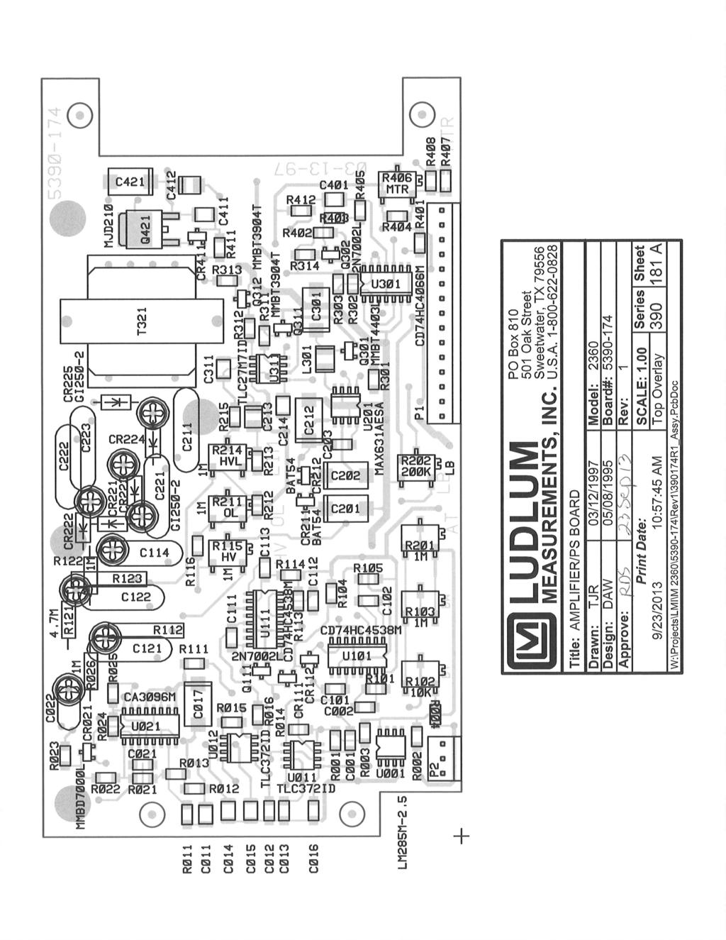
43 Model 2360 Technical Manual Section 8 Section 8 Technical Theory of Operation Refer to Amplifier/Power Supply Board Drawing for the following: Detector Input/Amplifier Negative-going detector pulses are coupled from the detector through C022 to Amplifier U021. R023 and CR021 protect the input of U021 from inadvertent shorts. Self-biased amplifier U021 provides gain in proportion to R021 divided by R022. Transistor pins 4, 5, and 6 of U021, provide amplification. Pins 12 and 15 of U021 are coupled as a constant current source to pin 6 of U021. The output self biases to 2Vbe (approximately 1.4 volts) at pin 7 of U021. This provides just enough bias current through pin 6 of U021 to conduct all of the current for the constant current source. Positive pulses from pin 7 of U021 are coupled to the discriminators through R011 and C011. Alpha/Beta Discriminator Positive pulses from amplifier U021 are coupled to comparator U012, pin 6, for alpha discrimination and pins 6 and 2 of U011 for beta discrimination. R201, alpha threshold, provides the reference voltage for alpha comparator U012. R102, beta threshold (defined as the lower threshold limit of the beta counting window), provides the reference voltage for beta threshold comparator pins 1, 2, and 3 of U011. R104, beta window (defined as the upper threshold limit of the beta counting window), provides the reference voltage for the beta window comparator pins 5, 6, and 7 of U011. Alpha/Beta Discriminator Logic Circuit Alpha pulses from U012 are coupled to univibrator U111. Pulses at pin 6 of U111 are inverted by Q111 for connection to reset (R) pins 3, 13 of U101. Pin 9 of U111 provides the pulses to be counted by the microprocessor (µp). Pulses from pin 9 of U111 are connected to pin 3 of U111 to provide a time delay for the µp clock cycle to complete before the next alpha pulse can be recognized by the µp. Ludlum Measurements, Inc. Page 8-1 July 2016
44 Model 2360 Technical Manual Section 8 Beta pulses from pin 1 of U011 are coupled to univibrator U101. Pulses are coupled to the µp from pin 7 of U101 as long as pins 3 and 13 of U011 remain high (+5 V). When an alpha and/or a beta window pulse is present, the reset (pins 3 and 13 of U101) function is enabled, and 7 of U101 remains high. Pin 7 of U101 is connected to pin 13 of U101 to provide a time delay for the µp clock cycle to complete before the next beta pulse can be recognized by the µp. Low Voltage Supply Battery voltage is coupled to switching regulator U201 and associated components to provide +5 V to power op-amps and logic circuitry. The charge pump (cp) output C202, CR211, CR212, and C201 form a voltage doubler circuit to provide +9 V for U201 amplifier supply. U001 and related components provide +2.5 V reference for HV SET and alpha/beta discriminator controls. R201 (LO BAT) is adjusted so that the meter pointer is aligned with the left vertical mark on the BAT OK line with 2.2 V battery input. High Voltage Supply High voltage is developed by blocking oscillator Q421, T321, C412, and rectified by voltage multiplier CR221-CR224, C221-C223, C211, and C114. High voltage increases as current through Q421 increases, with maximum output voltage with Q421 saturated. High voltage is coupled back through R123 to op-amp pin 2 of U311. Resistor network R completes the HV division circuit to ground. R214 provides HV limit at 2.0 kv when the HV SET control on the calibration board is at maximum. The regulated HV output is controlled by HV potentiometer located under the CAL cover on the front panel. This control provides the reference for comparator pin 3, U311. During stable operation, the voltage at pin 2 of U311 will equal the voltage at pin 3 of U311. Pin 1 of U311 will cause conduction of Q312 to increase or decrease until the HV finds a level of stability. R115 (HV TEST) calibrates the analog meter to the HV output when the HV test push-button switch is depressed. Detector Overload A voltage drop is developed across R121 and sensed by comparator U012 as detector current increases. When the voltage at pin 3 of U012 goes below pin 2, pin 1 goes low, illuminating the OL LED and driving the meter to full scale. R211, overload, provides adjustment for the overload set point. Ludlum Measurements, Inc. Page 8-2 July 2016
45 Model 2360 Technical Manual Section 8 Meter Drive Pulses are coupled from the µp board to the gate of Q302. Q302 inverts the pulses at CR403, and C401 provides integration. Integrated meter drive voltage is coupled from P1-13 via the battery (BAT) and HV test switch to pin 5 of U311. The meter is driven by the emitter of Q111, coupled as a voltage follower in conjunction with pin 6 and 7 of U311. R406, Meter Cal, is adjusted to calibrate the ratemeter reading corresponding to the incoming count rate. R407 and R408 provide temperature compensation for changes in the meter resistance due to temperature variations. Refer to Processor Board Drawing for the following: Power supply Battery voltage is coupled to switching regulator U321 and associated components to provide +5 V to power the µp and display drivers U211, 212. R101, C101, Q101, and Q201 form a delay switch, which allows U321 to stabilize before the load current is connected to the +5 V supply. Microprocessor (µp) U111, Intel N87C51FC, controls all of the data, control inputs, and display information. The clock frequency is crystal controlled by Y111 and related components at MHz. The µp incorporates internal memory (ROM) storing the program information. C211 resets the µp at power-up to initiate the start of the program routine. During the program loop the µp looks at all of the input switches for initiation or status changes and responds accordingly. The µp uses pulse-width modulation to control the analog ratemeter. The analog output, RATE (P1-3) is divided into 255 increments in a 166 µs period. At full meter deflection the low pulse period leading edge to leading edge will be 166 µs, 500 cpm = 163 µs, 400 cpm = 130 µs, 200 cpm = 65 µs, 100 cpm = 33 µs, and 0 = no pulse or +5 V. The pulses are inverted by Q302 on the amp/power supply board and then integrated by R403, C401. LCD Drive U101 and U001 make up the liquid crystal display drive circuitry. The display information is sent from the µp to U101 and U001 via DATA 0-1 lines. Each bit is latched into the drivers when the CLOCK line is brought high, then low by the µp. When 32 bits have been clocked to the drivers, the Ludlum Measurements, Inc. Page 8-3 July 2016
46 Model 2360 Technical Manual Section 8 LOAD line is brought high, and then low. The corresponding digits and segments are illuminated, corresponding to the stored-count information from the µp. Audio Alpha and/or beta audio pulse frequency is generated by the µp and coupled to Q211. Q211 then inverts the pulses and drives the low side of the audio transformer T321. Front-panel VOL control provides the bias voltage to the top of T321. Secondary winding of T321 is coupled to unimorph speaker via front-panel audio jack. Ludlum Measurements, Inc. Page 8-4 July 2016
47 Model 2360 Technical Manual Section 9 Section 9 Troubleshooting Occasionally, you may encounter problems with your LMI instrument or detector that may be repaired or resolved in the field, saving turn-around time and expense in returning the instrument to us for repair. Toward that end, LMI electronics technicians offer the following tips for troubleshooting the most common problems. Where several steps are given, perform them in order until the problem is corrected. Keep in mind that the most common problems encountered with this particular instrument are: (1) detector cables, (2) sticky meters, (3) battery contacts. Note that the first troubleshooting tip is for determining whether the problem is with the electronics or with the detector. A Ludlum Model 500 Pulser can be invaluable at this point because of its ability to simultaneously check high voltage, input sensitivity or threshold, and the electronics for proper counting. We hope these tips will prove to be helpful. As always, please call if you encounter difficulty in resolving a problem or if you have any questions. Troubleshooting Electronics that Utilize Proportional and Scintillator Type Detectors SYMPTOM No power (or meter does not reach BAT TEST or BAT OK mark) POSSIBLE SOLUTION 1. Check batteries and replace if weak. 2. Check polarity (see marks inside battery lid). Are the batteries installed backwards? Ludlum Measurements, Inc. Page 9-1 July 2016
48 Model 2360 Technical Manual Section 9 SYMPTOM No power (or meter does not reach BAT TEST or BAT OK mark) (continued) POSSIBLE SOLUTION 3. Check battery contacts. Clean them with rough sandpaper or use an engraver to clean the tips. 4. Check for loose or broken wires, especially between the main board and the calibration board. Nonlinear Readings 1. Check the high voltage (HV) by using a Ludlum Model 500 Pulser (or equivalent). If a multimeter is used to check the HV, ensure that one with high impedance is used, as a standard multimeter could be damaged in this process. 2. Check for noise in the detector cable by disconnecting the detector, placing the instrument on the lowest range setting, and wiggling the cable while observing the meter face for significant changes in readings. 3. Check for sticky meter movement. Does the reading change when you tap the meter? Does the meter needle stick at any spot? 4. Check the meter zero. Turn the power OFF. The meter should come to rest on 0. Meter goes full scale or pegs out 1. Replace the detector cable to determine whether or not the cable has failed, causing excessive noise. 2. Check the HV and, if possible, the input threshold for proper setting. Ludlum Measurements, Inc. Page 9-2 July 2016
49 Model 2360 Technical Manual Section 9 SYMPTOM Meter goes full scale or pegs out (continued) POSSIBLE SOLUTION 3. Open the instrument can and check for loose wires. 4. Ensure that the instrument s can is properly attached. When attached properly, the speaker will be located on the left side of the instrument. If the can is on backwards, interference between the speaker and the input preamplifier may cause noise. Ludlum Measurements, Inc. Page 9-3 July 2016
50 Model 2360 Technical Manual Section 10 Section 10 Recycling L udlum Measurements, Inc. supports the recycling of the electronics products it produces for the purpose of protecting the environment and to comply with all regional, national, and international agencies that promote economically and environmentally sustainable recycling systems. To this end, Ludlum Measurements, Inc. strives to supply the consumer of its goods with information regarding reuse and recycling of the many different types of materials used in its products. With many different agencies public and private involved in this pursuit, it becomes evident that a myriad of methods can be used in the process of recycling. Therefore, Ludlum Measurements, Inc. does not suggest one particular method over another, but simply desires to inform its consumers of the range of recyclable materials present in its products, so that the user will have flexibility in following all local and federal laws. The following types of recyclable materials are present in Ludlum Measurements, Inc. electronics products and should be recycled separately. The list is not all-inclusive, nor does it suggest that all materials are present in each piece of equipment: Batteries Glass Aluminum and Stainless Steel Circuit Boards Plastics Liquid Crystal Display (LCD) Ludlum Measurements, Inc. products, which have been placed on the market after August 13, 2005, have been labeled with a symbol recognized internationally as the crossed-out wheelie bin. This notifies the consumer that the product is not to be mixed with unsorted municipal waste when discarding; each material must be separated. The symbol will be placed near the AC receptacle, except for portable equipment where it will be placed on the battery lid. The symbol appears as such: Ludlum Measurements, Inc. Page 10-1 July 2016
51 Model 2360 Technical Manual Section 11 Section 11 Parts List Model 2360 Scaler/Ratemeter Reference Description Part Number UNIT Completely Assembled Model 2360 Scaler/Ratemeter Amplifier/Power Supply Board, Drawing BOARD Completely Assembled Amplifier/ Power Supply Board CAPACITORS C PF, 100V C002 47PF, 100V C µF, 50V C µF, 100V C µF, 100V C µF, 50V C F, 50V C µF, 100V C017 10µF, 20V C021 10PF, 100V C PF, 3KV C101 47PF, 100V C102 47PF, 100V C111 47PF, 100V C112 47PF, 100V C113 47PF, 100V C µF, 3KV C µF, 3KV C µF, 3KV C201 10µF, 20V C202 10µF, 20V C PF, 100V C µF, 3KV C212 68µF, 6.3V C213 1µF, 35V Ludlum Measurements, Inc. Page 11-1 July 2016
52 Model 2360 Technical Manual Section 11 Reference Description Part Number C µF, 50V C µF, 3KV C µF, 3KV C µF, 3KV C301 68µF, 6.3V C311 01µF, 50V C401 1µF, 50V C411 1µF, 50V C412 1µF, 35V C421 68µF, 6.3V TRANSISTORS INTEGRATED CIRCUITS DIODES THERMISTOR Q111 2N7002L Q301 MMBT4403LT Q302 2N7002L Q311 MMBT3904T Q312 MMBT3904T Q421 MJD U001 LM285M U011 TLC372ID U012 TLC372ID U021 CA3096M U101 CD74HC4538M U111 CD74HC4538M U201 MAX631AESA U301 CD74HC4066M U311 TLC27M7ID CR021 MMBD7000LT CR111 MMBD914L CR112 MMBD914L CR211 BAT CR212 BAT CR221 GI CR222 GI CR223 GI CR224 GI CR225 GI CR411 MMBD914L R , G Ludlum Measurements, Inc. Page 11-2 July 2016
53 Model 2360 Technical Manual Section 11 Reference Description Part Number POTENTIOMETERS RESISTORS R102 10K, BETA THRESH R103 1M, BETA WIN R115 1M, (HV) HV READOUT R406 5K, METER CAL (MTR) R214 1M, HV LIMIT R201 1M, ALPHA THRESH R K, LO BAT (LB) R211 1M, OVERLOAD R K, 125mW, 1% R K, 125mW, 1% R K, 125mW, 1% R K, 125mW, 1% R , 125mW, 1% R K, 125mW, 1% R K, 125mW, 1% R K, 125mW, 1% R K, 125mW, 1% R K, 125mW, 1% R K, 125mW, 1% R K, 125mW, 1% R K, 125mW, 1% R K, 125mW, 1% R K, 125mW, 1% R M, 250mW, 5% R K, 125mW, 1% R K, 125mW, 1% R K, 125mW, 1% R , 125mW, 1% R112 1G R K, 125mW, 1% R K, 125mW, 1% R K, 125mW, 1% R M, 250mW, 5% R M, 250mW, 5% R123 1G R M, 125mW, 1% R M, 125mW, 1% R M, 125mW, 1% R K, 125mW, 1% R K, 125mW, 1% Ludlum Measurements, Inc. Page 11-3 July 2016
54 Model 2360 Technical Manual Section 11 Reference Description Part Number R K, 125mW, 1% R K, 125mW, 1% R K, 125mW, 1% R K, 125mW, 1% R K, 125mW, 1% R , 1/8W, 1% R K, 125mW, 1% R K, 125mW, 1% R K, 125mW, 1% R M, 125mW, 1% R , 125mW, 1% R , 125mW, 1% R K, 125mW, 1% CONNECTORS INDUCTOR TRANSFORMER P P MTA L µH T T/100T, 200T Processor Board, Drawing BOARD Completely Assembled Processor Board CRYSTALS CAPACITORS Y111 MICRO XTAL MHZ Y401 MICRO XTAL KHZ C111 27PF, 100V C112 27PF, 100V C211 4.µ, 20V C221 47µF, 10V C311 68µF, 6.3V C312 68µF, 6.3V C313 68µF, 6.3V C314 68µF, 6.3V C315 68µF, 6.3V C316 68µF, 6.3V C401 10PF, 100V C411 10µF, 20V C µF, 20V C422 10µF, 20V Ludlum Measurements, Inc. Page 11-4 July 2016
55 Model 2360 Technical Manual Section 11 Reference Description Part Number C µF, 20V TRANSISTORS INTEGRATED CIRCUITS DIODES SWITCH RESISTORS RESISTOR NETWORKS CONNECTORS Q101 TRANS-2N7002L Q102 TRANS-2N7002L Q211 TRANS-2N7002L U101 IC-24C65ISM U111 IC-N87C51FC * SOCKET P U201 IC-24C65ISM U202 IC-PCF8574TD U311 IC-LT1304CS U401 IC-PCF8593TD U421 IC-MAX220CSE CR211 CXSH-4 EB CR212 CXSH-4 EB CR401 MMBD914L CR402 MMBD914L S301 CONFIGURE SWITCH R , 125mW, 1% R , 125mW, 1% R K, 125mW, 1% R K, 125mW, 1% R M, 125mW, 1% R K, 125mW, 1% R K, 125mW, 1% R K, 125mW, 1% R K, 125mW, 1% R K, 125mW, 1% R K, 125mW, 1% R K, 125mW, 1% R K, 125mW, 1% RN201 NETWORK-220K RN211 NETWORK-220K P MTA P MTA P MTA Ludlum Measurements, Inc. Page 11-5 July 2016
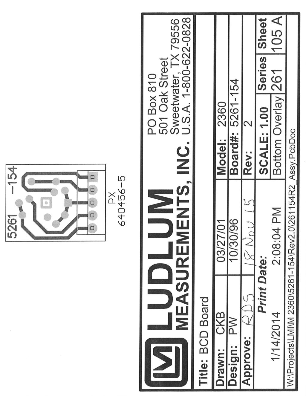
56 Model 2360 Technical Manual Section 11 Reference Description Part Number P MTA INDUCTOR BATTERY TRANSFORMER L211 22µH B411 DL2450 LITHIUM T321 XFMR- M 177 AUDIO LCD Display Board, Drawing BOARD Completely Assembled LCD Display Board CAPACITOR INTEGRATED CIRCUITS LEDS LCD RESISTORS C201 27PF, 100V U001 AY0438-I/L U101 AY0438-I/L DS001 E118, RED DS201 E118, RED DSP101 LCD-GD-7427WP 6 DIGIT R011 10K, 125mW, 1% R012 10K, 125mW, 1% R111 10K, 125mW, 1% R112 10K, 125mW, 1% Calibration Board, Drawing BOARD Completely Assembled Calibration Board POTENTIOMETER CONNECTOR R3 250K, HV SET P MTA BCD Board, Drawing BOARD Completely Assembled BCD Board SWITCH CONNECTOR S P MTA Ludlum Measurements, Inc. Page 11-6 July 2016
57 Model 2360 Technical Manual Section 11 Chassis Wiring Diagram, Drawing SWITCHES POTENTIOMETER CONNECTORS BATTERIES AUDIO MISCELLANEOUS Reference Description Part Number S1 SWITCH-PA S3 SWITCH-MPS-103F S4 PHONE JACK TINI #42A S5 SWITCH-7103SYZQE TOGGLE S6 SWITCH-7205SYZQE TOGGLE R1 10K, VOLUME J1 CONN MTA J2 CONN MTA J3 CONN MTA J4 CONN MTA J5 CONN MTA J6 D RECPT-RD9F000V3 9 PIN J7 JACK J8 CONN MTA J9 CONN MTA J12 CONN MTA J13 CONN MTA J14 Series C -UG706/U B1-B2 D DURACELL BATTERY DS1 S100RL-M, UNIMORPH M1 METER ASSEMBLY * METER-PORT BZL W/GLS * M2360 METERFACE * METER-MVT # MA * O RING-BEZEL * SPACER-#2 X.187 NYL * BATTERY CONTACT SET * MAIN HARNESS * LCD HARNESS * CAN-RS232 HARNESS Ludlum Measurements, Inc. Page 11-7 July 2016
58 Model 2360 Technical Manual Section 12 Section 12 Drawings and Diagrams MAIN BOARD, Drawing MAIN BOARD COMPONENT LAYOUT, Drawing A PROCESSOR BOARD, Drawing PROCESSOR BOARD COMPONENT LAYOUT, Drawing LCD DISPLAY BOARD, Drawing LCD DISPLAY BOARD COMPONENT LAYOUT, Drawing A (2 sheets) CALIBRATION BOARD, Drawing CALIBRATION BOARD COMPONENT LAYOUT, Drawing (2 sheets) BCD BOARD, Drawing BCD BOARD COMPONENT LAYOUT, Drawing A (2 sheets) WIRING DIAGRAM, Drawing Ludlum Measurements, Inc. Page 12-1 July 2016
59
60
61
62
63
64
65
66
67
68
69
70
71
LUDLUM MODEL 44-2 GAMMA SCINTILLATOR. February 2018 Serial Number PR and Succeeding Serial Numbers
 LUDLUM MODEL 44-2 GAMMA SCINTILLATOR February 2018 Serial Number PR361009 and Succeeding Serial Numbers LUDLUM MODEL 44-2 GAMMA SCINTILLATOR February 2018 Serial Number PR361009 and Succeeding Serial
LUDLUM MODEL 44-3 LOW ENERGY GAMMA SCINTILLATOR. May 2018 Serial Number PR and Succeeding Serial Numbers
 LUDLUM MODEL 44-3 LOW ENERGY GAMMA SCINTILLATOR May 2018 Serial Number PR134823 and Succeeding Serial Numbers LUDLUM MODEL 44-3 LOW ENERGY GAMMA SCINTILLATOR May 2018 Serial Number PR134823 and Succeeding
LUDLUM MODEL ALPHA, BETA, GAMMA HAND DETECTOR. June 2016 Serial Number and Succeeding Serial Numbers
 LUDLUM MODEL 44-25 ALPHA, BETA, GAMMA HAND DETECTOR June 2016 Serial Number 155835 and Succeeding Serial Numbers LUDLUM MODEL 44-25 ALPHA, BETA, GAMMA HAND DETECTOR June 2016 Serial Number 155835 and
LUDLUM MODEL AND LUDLUM MODEL ALPHA, BETA, & GAMMA DETECTORS
 LUDLUM MODEL 44-9-18 AND LUDLUM MODEL 44-9-19 ALPHA, BETA, & GAMMA DETECTORS January 2018 Serial Number PR254331 and Succeeding Serial Numbers LUDLUM MODEL 44-9-18 AND LUDLUM MODEL 44-9-19 ALPHA, BETA,
LUDLUM MODEL 44-7 Alpha, Beta, Gamma Detector. July 2012 Serial No. PR and succeeding Serial Numbers
 LUDLUM MODEL 44-7 Alpha, Beta, Gamma Detector July 2012 Serial No. PR090405 and succeeding Serial Numbers LUDLUM MODEL 44-7 Alpha, Beta, Gamma Detector July 2012 Serial No. PR090405 and succeeding Serial
LUDLUM MODEL 19A. Micro R Meter. May 2017 Serial No and Succeeding Serial Numbers
 LUDLUM MODEL 19A Micro R Meter May 2017 Serial No. 144020 and Succeeding Serial Numbers LUDLUM MODEL 19A Micro R Meter May 2017 Serial No. 144020 and Succeeding Serial Numbers Model 19A Micro R Meter
LUDLUM MODEL 25 AND 25-1 PERSONAL RADIATION MONITOR USER S MANUAL. October 2014 Serial Number and Succeeding Serial Numbers
 LUDLUM MODEL 25 AND 25-1 PERSONAL RADIATION MONITOR USER S MANUAL October 2014 Serial Number 25000100 and Succeeding Serial Numbers LUDLUM MODEL 25 AND 25-1 PERSONAL RADIATION MONITOR USER S MANUAL October
MODEL AND MODEL GAS PROPORTIONAL DETECTORS. December 2016 Serial No and Succeeding Serial Numbers
 MODEL 43-37 AND MODEL 43-37-1 GAS PROPORTIONAL DETECTORS Serial No. 086152 and Succeeding Serial Numbers MODEL 43-37 AND MODEL 43-37-1 GAS PROPORTIONAL DETECTORS Serial No. 086152 and Succeeding Serial
MODEL 23 AND 23-1 ELECTRONIC PERSONAL DOSIMETER. August 2017
 MODEL 23 AND 23-1 ELECTRONIC PERSONAL DOSIMETER August 2017 MODEL 23 AND 23-1 ELECTRONIC PERSONAL DOSIMETER August 2017 ii STATEMENT OF WARRANTY Ludlum Measurements, Inc. warrants the products covered
LUDLUM MODEL and PANCAKE CLUSTER DETECTORS. June 2016
 LUDLUM MODEL 44-89 and 44-94 PANCAKE CLUSTER DETECTORS June 2016 LUDLUM MODEL 44-89 and 44-94 PANCAKE CLUSTER DETECTORS June 2016 STATEMENT OF WARRANTY Ludlum Measurements, Inc. warrants the products covered
LUDLUM MODEL ALPHA/BETA RATEMETER. April 2018 Serial No and Succeeding Serial Numbers
 LUDLUM MODEL 177-84 ALPHA/BETA RATEMETER April 2018 Serial No. 128600 and Succeeding Serial Numbers LUDLUM MODEL 177-84 ALPHA/BETA RATEMETER April 2018 Serial No. 128600 and Succeeding Serial Numbers STATEMENT
LUDLUM MODEL 26 FRISKER USER S MANUAL. December 2016 Serial Number PF and Succeeding Serial Numbers
 LUDLUM MODEL 26 FRISKER USER S MANUAL December 2016 Serial Number PF001075 and Succeeding Serial Numbers LUDLUM MODEL 26 FRISKER USER S MANUAL December 2016 Serial Number PF001075 and Succeeding Serial
LUDLUM MODEL 26-1 FRISKER USER S MANUAL. April 2017 Serial Number PF and Succeeding Serial Numbers
 LUDLUM MODEL 26-1 FRISKER USER S MANUAL April 2017 Serial Number PF002366 and Succeeding Serial Numbers LUDLUM MODEL 26-1 FRISKER USER S MANUAL April 2017 Serial Number PF002366 and Succeeding Serial Numbers
LUDLUM MODEL 44-9 ALPHA, BETA, GAMMA DETECTOR. February 2010 Serial Number PR and Succeeding Serial Numbers
 LUDLUM MODEL 44-9 ALPHA, BETA, GAMMA DETECTOR February 2010 Serial Number PR090405 and Succeeding Serial Numbers LUDLUM MODEL 44-9 ALPHA, BETA, GAMMA DETECTOR February 2010 Serial Number PR090405 and
LUDLUM MODEL 3276 SERIES FRISKER/AREA MONITOR USER S MANUAL. November 2017 Serial Number: and Succeeding Firmware: 49830n30 and Higher
 LUDLUM MODEL 3276 SERIES FRISKER/AREA MONITOR USER S MANUAL November 2017 Serial Number: 25009185 and Succeeding Firmware: 49830n30 and Higher LUDLUM MODEL 3276 SERIES FRISKER/AREA MONITOR USER S MANUAL
LUDLUM MODEL ALARM RATEMETER. June 2017 Serial Number and Succeeding Serial Numbers
 LUDLUM MODEL 177-61 ALARM RATEMETER June 2017 Serial Number 101825 and Succeeding Serial Numbers LUDLUM MODEL 177-61 ALARM RATEMETER June 2017 Serial Number 101825 and Succeeding Serial Numbers STATEMENT
LUDLUM MODEL 35 SERIES DIGITAL SURVEY METER USER S MANUAL
 LUDLUM MODEL 35 SERIES DIGITAL SURVEY METER USER S MANUAL September 2016 LUDLUM MODEL 35 SERIES DIGITAL SURVEY METER USER S MANUAL September 2016 STATEMENT OF WARRANTY Ludlum Measurements, Inc. warrants
MODEL RWM RADIATION WASTE MONITOR LUDLUM MODEL RWM RADIATION WASTE MONITOR INSTALLATION MANUAL
 LUDLUM MODEL 3500-1000RWM RADIATION WASTE MONITOR INSTALLATION MANUAL August 2001 1 RECEIVING CONDITION EXAMINATION Be sure to verify that the shipping carton is received in good condition with no visible
LUDLUM MODEL 52 PORTABLE PORTAL MONITOR. November 2011 Serial No and Succeeding Serial Numbers
 LUDLUM MODEL 52 PORTABLE PORTAL MONITOR Serial No. 175872 and Succeeding Serial Numbers LUDLUM MODEL 52 PORTABLE PORTAL MONITOR Serial No. 175872 and Succeeding Serial Numbers TABLE OF CONTENTS 1. GENERAL...
Pipo Communications. Model ST-888. DTMF ANI/ENI Display Decoder
 Pipo Communications Model ST-888 DTMF ANI/ENI Display Decoder 1516 Cassil Place Hollywood, California 90028-7106 Phone: 323-466-5444 Fax: 323-466-1520 www.pipo.cc Manual # 68-9888 May 1, 2002 Rev. 5/02
Bacharach Bodyguard 4 User's Guide
 Bacharach Bodyguard 4 User's Guide This manual and the software described in it are copyrighted, with all rights reserved. Under the copyright laws, this manual or the software may not be copied, in whole
Contamination Meter Users Manual
 RDS-80 Contamination Meter U Users Manual Version 1.01 LAURUS Systems, Inc. - Ph: 410-465-5558 - Fax: 410-465-5257 - www.laurussystems.com NOTE This document and the information herewith are copyrighted
RAM GENE-1 ERK. Contamination & Radiation Meter. Operating Manual. Document #PRIR90N2.DOC Version 2.2 October 2009
 RAM GENE-1 ERK MK-Ι & MK-ΙΙ Contamination & Radiation Meter Operating Manual Document #PRIR90N2.DOC Version 2.2 October 2009 Version / Revision Log: RAM GENE-1 ERK/ Operating Manual Ver./Rev.# Date Revised
Sierra Series 900 Single & Dual Channel System. Instruction Manual
 Series 240/24 Instruction Manual Table of Contents Sierra Series 900 Single & Dual Channel System Instruction Manual Part Number IM-90-07/05 Revision D. 5 Harris Court, Building L Monterey, CA 93940 (83)
RAM GENE / RAM GENE-1
 RAM GENE / RAM GENE-1 Radiation Meters Operating Manual Document #PRIR69N0.DOC Version 6.1 - December 2000 ROTEM INDUSTRIES LTD. ROTEM Industrial Park P.O.Box 9046, Beer-Sheva 84190, ISRAEL Tel: 972-8-6571312/6568652
OPERATOR S MANUAL MODEL AP15/AP15-1/AP15-2 PC-ALARM PANEL
 ap15_2manual04/22/13 Page 1 4/22/2013 1 Serial Number : Option: OPERATOR S MANUAL MODEL AP15/AP15-1/AP15-2 PC-ALARM PANEL Micro Seven, Inc. 1095-K N.E. 25th Hillsboro, OR 97124 U.S.A. phone: 503-693-6982
Mark 25 Ultrapure Water Conductivity Analyzer
 Martek Instruments, Inc. Mark 25 Ultrapure Water Conductivity Analyzer Instruction Manual WARRANTY POLICY Unless otherwise stated, MARTEK INSTRUMENTS, INC. warrants this equipment to be free from defects
CO2 RESPONDER Portable Carbon Dioxide Detector QUICK REFERENCE GUIDE
 CO2 RESPONDER Portable Carbon Dioxide Detector QUICK REFERENCE GUIDE GasAlertMicro 5 IR from Refer to for more details. Manual provided on CD with unit at time of purchase 2 Table of Contents Getting Started.
ModSync Sequencing System Installation & Operation Manual. For use with Fulton Steam Boilers.
 ModSync Sequencing System Installation & Operation Manual For use with Fulton Steam Boilers. Revision 3.0 8/21/2008 - 2 - Table of Contents Introduction Page 4 Features Page 4 Sequence of Operation Page
OVEN INDUSTRIES, INC.
 OVEN INDUSTRIES, INC. OPERATING MANUAL Model 5C7-252 TEMPERATURE CONTROLLER With PLC Inputs Introduction Thank you for purchasing our controller. The Model 5C7-252 is an exceptionally versatile unit and
Sierra Model 951 Digital Flo-Box. Instruction Manual Part Number IM-951 Revision A 09-05
 Sierra Model 951 Digital Flo-Box Instruction Manual Part Number IM-951 Revision A 09-05 5 Harris Court, Building L Monterey, CA 93940 (831) 373-0200 (800) 866-0200 Fax (831) 373-4402 www.sierrainstruments.com
OPERATING MANUAL. EchoTherm PROGRAMMABLE DIGITAL CHILLING INCUBATOR MODELS IN35, IN45 and IN55-12VDC. DOCUMENT NUMBER IN35-03 Revised 15 May 2015
 OPERATING MANUAL EchoTherm PROGRAMMABLE DIGITAL CHILLING INCUBATOR MODELS IN35, IN45 and IN55-12VDC DOCUMENT NUMBER IN35-03 Revised 15 May 2015 TORREY PINES SCIENTIFIC, INC. 2713 Loker Ave. West Carlsbad,
Beacon 800 Gas Monitor Operator s Manual
 Beacon 800 Gas Monitor Operator s Manual Part Number: 71-0037RK Revision: F Released: 4/18/17 www.rkiinstruments.com Product Warranty RKI Instruments, Inc. warrants gas alarm equipment sold by us to be
Omniguard 4: Features
 OMNIGUARD 4 The clear choice for monitoring and documenting Vacuum and Pressure in a containment area. Ideal for Asbestos, Lead and Mold abatement and Clean Room monitoring. Omniguard 4: Features The Omniguard
Table of Contents SECTION PAGE SECTION 1 INTRODUCTION Description Features Models... SECTION 2 RS-232 COMMUNICATIONS...
 SECTION Table of Contents SECTION 1 INTRODUCTION...................... 1.1 Description............................... 1.2 Features................................. 1.3 Models..................................
Instruction Manual WARNING
 Controllers Instruction Manual WARNING THIS MANAUL MUST BE CAREFULLY READ BY ALL INDIVIDUALS WHO HAVE OR WILL HAVE THE RESPONSIBILITY FOR INSTALLING, USING OR SERVICING THIS PRODUCT. Like any piece of
Beacon 200 Gas Monitor Operator s Manual. Part Number: RK Released: 6/6/08
 Beacon 200 Gas Monitor Operator s Manual Part Number: 71-2102RK Released: 6/6/08 Table of Contents Chapter 1: Introduction.................................................3 Overview.............................................................3
DICKSON KT6 DICKSON. Temperature Chart Recorder. Specifications. Product. Display Symbols. Information & Operating. Contents:
 KT6 Temperature Chart Recorder Contents: Instructions, Alarm Relays & Started / Accessories Calibration, Warranty / Factory Service & Order Form Temperature Ranges (user selectable): Recorder Accuracy:
GG-2 2-CHANNEL GAS DETECTION CONTROL PANEL. Installation and Operation Manual
 GG-2 2-CHANNEL GAS DETECTION CONTROL PANEL Installation and Operation Manual 2 GG-2 Warning Use this product only in the manner described in this manual. If the equipment is used in a manner not specified
INSTALLATION INSTRUCTIONS
 TT-1343 5/06b INSTALLATION INSTRUCTIONS Original Issue Date: 8/03 Model: Automatic Transfer Switches Equipped with Series 1000 Programmable Controller Market: ATS Subject: Remote Annunciator Kits GM28938-KP1,
Refer to Bulletin E-1101 for detailed information on the FLAME-MONITOR System.
 The Fireye EP260, EP270 (early spark termination), or EP265 (pilot stabilization) programmer modules are used with the FLAME-MONITOR Burner Management Control System (P/N E110). Several operational characteristics
NexSysLink. 2 CAN Display Operation Manual. CAN Instruments Product Family
 NexSysLink CAN Instruments Product Family 2 CAN Display Operation Manual Contact Beede Beede Electrical Instrument Company, Inc. 88 Village Street Penacook, NH 03303 (603) 753-6362 Toll-free 800-451-8255
275HVD NON-CONTACT, HIGH VOLTAGE DETECTOR DETECTOR DE ALTA TENSIÓN SIN CONTACTO
 99 Washington Street Melrose, MA 02176 Phone 781-665-1400 Toll Free 1-800-517-8431 Visit us at www.testequipmentdepot.com 275HVD NON-CONTACT, HIGH VOLTAGE DETECTOR DETECTOR DE ALTA TENSIÓN SIN CONTACTO
Controllers. Instruction Manual WARNING
 Controllers Instruction Manual WARNING THIS MANUAL MUST BE CAREFULLY READ BY ALL INDIVIDUALS WHO HAVE OR WILL HAVE THE RESPONSIBILITY FOR INSTALLING, USING OR SERVICING THIS PRODUCT. Like any piece of
MGC Dock User s Manual
 User s Manual Contents Warnings Statements/Avertisseement... 3 READ FIRST BEFORE OPERATION... 3 Description... 4 Basic Operation... 5 Clip Dock Components... 5 LEDs... 5 User Operation... 6 Turning the
MGC Dock User s Manual
 Operator s Manual Contents Warnings Statements/Avertisseement... 3 READ FIRST BEFORE OPERATION... 3 Basic Operation... 4 Clip Dock Components... 4 LEDs... 4 Operation... 5 Turning the Clip Dock On and
DYGIZONE GJD910 Lighting Controller & Enunciator
 DYGIZONE GJD910 Lighting Controller & Enunciator MASTER WIRING IDENTIFICATION Power up to the DygiZone and you will see: All the LED s (red,yellow,green and blue buttons) will flash All the LCD icons will
CONsOlIDATOR 4 & 8. MulTI- C h ANNEl CONTROllERs. ConsoliDator 4 Model PD940 ConsoliDator 4 Features. ConsoliDator 8 Features.
 CONsOlIDATOR 4 & 8 MulTI- C h ANNEl CONTROllERs ConsoliDator 4 Model PD940 ConsoliDator 4 Features Four 4-20 Four 4-20 Outputs ConsoliDator 8 Features Eight 4-20 Two 4-20 Outputs Common Features Four Pulse
Carbon Monoxide Transmitter
 Introduction The CO Transmitter uses an electrochemical sensor to monitor the carbon monoxide level and outputs a field-selectable 4-20 ma or voltage signal. The voltage signal may also be set to 0-5 or
A1UL PERS. Personal Emergency Response System. For Technical Support Please Contact Your Service Provider Or Distributor
 A1UL PERS Personal Emergency Response System TABLE OF CONTENTS 1. READ THIS FIRST... 1 2. SYSTEM OVERVIEW.. 1 3. COMPONENTS 2 4. UNIT OPERATION! Standby Mode.. 3! Emergency Activation. 3! Answering Incoming
OPERATING MANUAL MOLECULAR DIMENSIONS, INC. PROGRAMMABLE DIGITAL CHILLING INCUBATOR MODELS MD5-601 AND MD5-603
 OPERATING MANUAL MOLECULAR DIMENSIONS, INC. PROGRAMMABLE DIGITAL CHILLING INCUBATOR MODELS MD5-601 AND MD5-603 DOCUMENT NUMBER DM5-601/603-1 January 21, 2011 MOLECULAR DIMENSIONS, INC. United Kingdom Office
USER MANUAL USB Multi-Function Datalogger Model RHT35
 USER MANUAL USB Multi-Function Datalogger Model RHT35 Additional User Manual Translations available at www.extech.com Introduction Thank you for selecting the Extech multi-function, easy-to-use, portable
OI-2400-DOCK Multi Gas Docking Station. Operation Manual trevision 2.2w
 OI-2400-DOCK Multi Gas Docking Station Operation Manual trevision 2.2w Table of Contents Introduction... 3 Warnings Statements/Avertisseement... 4 Basic Operation... 5 OI-2400-DOCK Components... 5 LEDs...
SENSIT HXG-2d. SENSIT TECHNOLOGIES 851 Transport Drive Valparaiso, IN Phone: (219) Fax: (219)
 Fax: (219)") WARRANTY AND REPAIR POLICY Your SENSIT HXG-2d instrument is warranted to be free from defects in materials and workmanship for a period of two years after purchase (excluding sensor, calibration and batteries).
WARRANTY AND REPAIR POLICY Your SENSIT HXG-2d instrument is warranted to be free from defects in materials and workmanship for a period of two years after purchase (excluding sensor, calibration and batteries).
HIn3550 Magnetic Field Monitor User's Manual
 HIn3550 Magnetic Field Monitor User's Manual Copyright 1993 by Holaday Industries, Inc. Manual #600053 10/97 $12.50 Revision Record Manual #600053 HIn3550 Magnetic Field Monitor Revision Description Date
The Kryos LN2 Liquid Level Control & Cryogenic Temperature Control
 The Kryos LN2 Liquid Level Control & Cryogenic Temperature Control Created for Taylor-Wharton Gas Equipment By Pacer Digital Systems, Inc. INTRODUCTION... 4 TEXT FORMAT NOTATION... 4 SYSTEM COMPONENTS...
IntelliPack : 800 Series
 800 Series Models by Function Guide 800T Intelligent Transmitters 800A Intelligent Alarms 890M Math/Computation IntelliPack transmitter units convert sensor inputs to isolated process current or voltage
LUDLUM MODEL RK RESPONSE KIT. January 2016 Serial Number and Succeeding Serial Numbers
 LUDLUM MODEL 2241-2RK RESPONSE KIT January 2016 Serial Number 237627 and Succeeding Serial Numbers LUDLUM MODEL 2241-2RK RESPONSE KIT January 2016 Serial Number 237627 and Succeeding Serial Numbers STATEMENT
II 2 G. SENSIT HXG-2d. Ex ib IIB T3 IP20. Suitable for combustible gases such as Methane, Butane, Propane and Natural Gas MADE IN USA
 SENSIT HXG-2d Combustible Gas Detector INSTRUCTION MANUAL Read and understand Instructions before use. PENDING II 2 G Ex ib IIB T3 IP20 PENDING (USA) Class 1, Division 1, Groups C and D, T3 Suitable for
Adaptive CyCLO Technical and HMI User Guide. CyCLO User Guide. Version th December 2017 REV
 CyCLO User Guide Version 2.00 19 th December 2017 REV 2.00 1 Contents 1. Hardware... 3 1.1. Introduction... 3 1.2. Electrical Specification... 3 1.3. Board Overview... 4 1.4. Electrical Installation...
AUTOMATION. Operator s Manual RST Series Web Enabled Input Module. Rev. A2, 1/12
 AUTOMATION P R O D U C T S GROUP, INC. Operator s Manual RST-5000 Series Web Enabled Input Module Rev. A2, 1/12 Tel: 1/888/525-7300 Fax: 1/435/753-7490 www.apgsensors.com E-mail: sales@apgsensors.com RST-5000
F PC and AO OUTPUT BOARDS INSTRUCTION MANUAL. Blue-White. Industries, Ltd.
 F-2000 PC and AO OUTPUT BOARDS INSTRUCTION MANUAL Blue-White R Industries, Ltd. 500 Business Drive Huntington Beach, CA 92649 USA Phone: 714-89-8529 FAX: 714-894-9492 E mail: sales@blue-white.com or techsupport@blue-white.com
LUDLUM MODEL RK2 RESPONSE KIT. October 2017 Serial Number and Succeeding Serial Numbers
 LUDLUM MODEL 2241-3RK2 RESPONSE KIT October 2017 Serial Number 238342 and Succeeding Serial Numbers LUDLUM MODEL 2241-3RK2 RESPONSE KIT October 2017 Serial Number 238342 and Succeeding Serial Numbers STATEMENT
Alarm Panel [ PRELIMINARY HARDWARE MANUAL ] USER MANUAL. v1.0a. May 7, 2008 D-OC-UM
![Alarm Panel [ PRELIMINARY HARDWARE MANUAL ] USER MANUAL. v1.0a. May 7, 2008 D-OC-UM](/thumbs/86/93788073.jpg "Alarm Panel [ PRELIMINARY HARDWARE MANUAL ] USER MANUAL. v1.0a. May 7, 2008 D-OC-UM") Alarm Panel USER MANUAL [ PRELIMINARY HARDWARE MANUAL ] Visit our website at www.dpstelecom.com for the latest PDF manual and FAQs. May 7, 2008 D-OC-UM085.07010 v1.0a Revision History April 28, 2008 May
Alarm Panel USER MANUAL [ PRELIMINARY HARDWARE MANUAL ] Visit our website at www.dpstelecom.com for the latest PDF manual and FAQs. May 7, 2008 D-OC-UM085.07010 v1.0a Revision History April 28, 2008 May
Apollo Intelligent Auto Aligning Beam Detector. User Guide
 Apollo Intelligent Auto Aligning Beam Detector User Guide EN 1. General Information 50cm 50cm 8-100m Ensure clear line of sight from Detector to Reflector Mount on solid surfaces (structural wall or girder)
GASGUARDIAN Channel Controller OPERATING & INSTALLATION MANUAL
 GASGUARDIAN 2 3 2-Channel Controller OPERATING & INSTALLATION MANUAL GasGuardian 2 3 Operating and Installation Manual Table of Contents General description.... 3 Installation. 3 Locating the GasGuardian-2..
Model: LD5 Dual Mode Refrigerant Gas Leak Detector. Operating Instructions
 99 Washington Street Melrose, MA 02176 Phone 781-665-1400 Toll Free 1-800-517-8431 Visit us at www.testequipmentdepot.com Operating Instructions Model: LD5 Dual Mode Refrigerant Gas Leak Detector PAGE
ENGINE MONITOR VOTT MODEL: YEAR WARRANTY
 INSTRUCTION MANUAL ENGINE MONITOR VOTT MODEL: 023-4400-0 3 YEAR WARRANTY INTRODUCTION The VOTT meter is an ideal engine monitor, which displays data via the J1939 CAN Bus. The meter utilizes a large LCD
Falcon-II Next Generation, Air Quality Monitor CO2 & Temperature
 Critical Environment Technologies Canada Inc. Falcon-II Next Generation, Air Quality Monitor CO2 & Temperature OPERATION MANUAL REV: A JUNE-2-2008 #145, 7391 Vantage Way Delta, BC V4G 1M3 Canada Phone:
USB Multi Function Dataloggers. RHT30 Humidity/Temperature Datalogger. TH30 Dual Temperature Datalogger
 USER MANUAL USB Multi Function Dataloggers RHT30 Humidity/Temperature Datalogger TH30 Dual Temperature Datalogger Additional User Manual Translations available at www.extech.com Introduction Thank you
TECHNICAL MANUAL CVM 20 C 5005 CV/04-99 GB
 Summary 1 CONNECTIONS... 3 1.1 TEMPERATURE PROBES...3 1.2 LOW VOLTAGE DIGITAL INPUTS...3 1.3 LIVE DIGITAL INPUTS...4 1.4 RELAY OUTPUTS...5 2 POWER SUPPLY... 6 3 SERIAL CONNECTIONS... 6 4 SOFTWARE... 7
LUDLUM MODEL DATA LOGGER
 LUDLUM MODEL 2350-1 DATA LOGGER February 2017 Serial No. 126167 and Succeeding Serial Numbers CPU Firmware 37122N32 I/O Firmware 37123N05 LUDLUM MODEL 2350-1 DATA LOGGER February 2017 Serial No. 126167
THL2. Temperature/Humidity USB Datalogger INSTRUCTION MANUAL
 The THL2 is compatible with computers using Windows 2000, XP, Vista, Windows 7 and Windows 8. INSTRUCTION MANUAL 2 THL2 1-800-547-5740 Fax: (503) 643-6322 www.ueitest.com email: info@ueitest.com Temperature/Humidity
Laptop / PC Programming Manual
 Laptop / PC Programming Manual Doc. # Fire PC Program rev B 01.07 This Document is property of Evax Systems, Inc. The Evax Fire Solutions Programmer Components 2 1.0 System Setup 4 1.1 Interface Setup
MODEL 5800A CARBON MONOXIDE (CO) MONITOR AND ALARM SAMPLE-DRAWING TYPE
 MONITOR AND ALARM SAMPLE-DRAWING TYPE") MODEL 5800A CARBON MONOXIDE (CO) MONITOR AND ALARM SAMPLE-DRAWING TYPE 11//07 A153-021500-1 INSTRUCTION MANUAL - MODEL 5800A CO ALARM I INTRODUCTION This MST Model 5800A Carbon Monoxide (CO) Alarm is a
MODEL 5800A CARBON MONOXIDE (CO) MONITOR AND ALARM SAMPLE-DRAWING TYPE 11//07 A153-021500-1 INSTRUCTION MANUAL - MODEL 5800A CO ALARM I INTRODUCTION This MST Model 5800A Carbon Monoxide (CO) Alarm is a
MYRIAD TRIPLEX PUMP CONTROLLER INSTRUCTION MANUAL
 MYRIAD TRIPLEX PUMP CONTROLLER INSTRUCTION MANUAL MYRIAD TPC VISIT OUR WEBSITE SIGMACONTROLS.COM MYRIADI&O062705 2 TABLE OF CONTENTS INTRODUCTION 3 Ordering Information Specifications Features WIRING 7,8
User Manual. Humidity-Temperature Chart Recorder. Model RH520
 User Manual Humidity-Temperature Chart Recorder Model RH520 Introduction Congratulations on your purchase of the Extech RH520 Temperature + Humidity Chart Recorder. The RH520 measures and displays Temperature,
ESSEX ENGINEERING CORPORATION
 WATER/WASTEWATER TREATMENT CONTROL SYSTEMS AND SUBSYSTEMS 2000 SERIES CONTROL SYSTEMS: 2000 series are for surface mounting inside a control cabinet Model 2024 Electronic Alternator Duplex (two pump) pump
INSTALLATION. and INSTRUCTION MANUAL. for QUALITY AIR BREATHING SYSTEMS. Model ABM - 700
 INSTALLATION and INSTRUCTION MANUAL for QUALITY AIR BREATHING SYSTEMS Model ABM - 700 M A R T E C H S E R V I C E S C O M P A N Y P.O. Box 7079 OFFICE: 800-831-1525 Mazeppa, MN 55956 Fax : (507)843-4953
Introduction. OM-THA2
 Introduction. The OM-THA2 is a multi-function product that monitors Temperature, Humidity and Dew Point, provides alarms for out of range conditions, and continuously logs data. It consists of a base unit
INSTALLATION. and INSTRUCTION MANUAL. for QUALITY AIR BREATHING SYSTEMS. Model ABM - 715
 INSTALLATION and INSTRUCTION MANUAL for QUALITY AIR BREATHING SYSTEMS Model ABM - 715 M A R T E C H S E R V I C E S C O M P A N Y P.O. Box 7079 OFFICE: 800-831-1525 Mazeppa, MN 55956 Fax : (507)843-4953
HOBO U14 Data Logger User Manual
 HOBO U14 Data Logger User Manual The U family of data loggers offers reliability and convenient monitoring for applications that require higher accuracy, better resolution, more memory, or USB connectivity
LUMA-NET 804CP / 808CP REMOTE CONTROL PANEL
 LUMA-NET 804CP / 808CP REMOTE CONTROL PANEL INSTALLATION AND OPERATION GUIDE INTRODUCTION The NSI 804CP and 808CP represents a key part of a state of the art, total lighting control system. Combined with
Communications None RS-232C RS-422* RS-485* BCD Transmission output*/** (4 to 20 ma) E5AX- E5AX- L(M)A02 L(M)A03
 E5AX- E5AX- L(M)A02 L(M)A03") Digital Controller A 96 x 96-mm (DIN) Digital Process Controller Optimum PID control with feed-forward control circuitry. High accuracy (+0.3% FS +1 digit max.). Replaceable Output Units. Models with communications
Digital Controller A 96 x 96-mm (DIN) Digital Process Controller Optimum PID control with feed-forward control circuitry. High accuracy (+0.3% FS +1 digit max.). Replaceable Output Units. Models with communications
GasScanner 1C. Single Channel Monitor. Operator s Manual. MINT-0278-XX Rev A
 GasScanner 1C Single Channel Monitor Operator s Manual MINT-0278-XX Rev A Product Warranty Matheson Tri-Gas, Inc., warrants gas alarm equipment sold by us to be free from defects in materials, workmanship,
SENSIT HXG-2d Combustible Gas Detector
 INSTRUCTION MANUAL SENSIT HXG-2d Combustible Gas Detector Read and understand instructions before use. 710183 UL 913 Intrinsically Safe for Use in Class I, Groups C and D, T3 Hazardous Locations For use
Identify the following features and specifications for the ESP1
 LEARNING OBJECTIVES: 2.17.01 List the factors which affect an RCT's selection of a portable contamination monitoring instrument, and identify appropriate instruments for contamination monitoring. (Also
Table of Contents. Part I SAFETY MESSAGE TO INSTALLERS OF EMERGENCY WARNING EQUIPMENT 2 Part II Vehicle Operation 4. Part III Safety Messages 13
 Manual I SS2000 TouchScreen Installation Guide Table of Contents Foreword 0 Part I SAFETY MESSAGE TO INSTALLERS OF EMERGENCY WARNING EQUIPMENT 2 Part II Vehicle Operation 4 1 Installing the... SS2000 TouchScreen
Automatic Phone-Out Home Monitoring Systems
 Automatic Phone-Out Home Monitoring Systems Power Outage, Freeze and Flood Alarm Product Description Model Number: THP201 These monitoring systems are intended to monitor homes, cabins, and other premises
Sentry LIQUID LEVEL GAUGE MODEL 200 or 200C OWNER MANUAL REV 1.7 SEPT08 PAGE 1 OF 12
 PAGE 1 OF 12 TABLE OF CONTENTS PAGE 1. SAFETY PRECAUTIONS 1.1. Electrical shock 3 2. APPLICATION 3 3. INSTALLATION 3.1. Mount indoor alarm display 3.2. Mount the outdoor junction box 3.3. Install interconnecting
Nov 08 PRODUCT SPECIFICATION SHEET
 Honeywell UDC1200 and UDC1700 MICRO-PRO SERIES UNIVERSAL DIGITAL CONTROLLERS 51-52-03-35 Nov 08 PRODUCT SPECIFICATION SHEET OVERVIEW The UDC1200 & UDC1700 are microprocessor-based 1/16 DIN and 1/8 DIN
GasScanner 8C. Eight Channel Monitor. Operator s Manual. MINT-0281-XX Rev. A 01/29/08
 GasScanner 8C Eight Channel Monitor Operator s Manual MINT-0281-XX Rev. A 01/29/08 Product Warranty Matheson Tri-Gas, Inc., warrants gas alarm equipment sold by us to be free from defects in materials,
SEC 2000 Millenium Infrared Gas Detector
 SEC 2000 Millenium Infrared Gas Detector Instruction and Operation Manual Sensor Electronics Corporation 5500 Lincoln Drive Minneapolis, Minnesota 55436 USA (952) 938-9486 Fax (952) 938-9617 Email: sales@sensorelectronic.com
Pakton Technologies Pty Ltd ABN Ferrier Road, Narangba Qld 4504
 Remote Monitor PTE0700 SECURITY ELECTRONICS User Manual PTE0700 V2 Series Remote Monitor Pakton Technologies Pty Ltd ABN 66 405 694 842 16 Ferrier Road, Narangba Qld 4504 PO Box 408, Narangba QLD 4504
LUDLUM MODEL 334AB ALPHA/BETA PARTICULATE MONITOR. December 2016
 LUDLUM MODEL 334AB ALPHA/BETA PARTICULATE MONITOR December 2016 LUDLUM MEASUREMENTS, INC Model 334AB Operations Manual Documentation version 2.0 December 2016 NO WARRANTY. The technical documentation
725B Configuration Software Manual
 725B Configuration Software Manual REV DATED DESCRIPTION AUTHOR APPROVED 0 09-03-10 First Issue P.Cartmell Page 1 of 80 SECTION 1 - SOFTWARE INSTALLATION... 5 725B ConfigurationSoftware Installation...
Operating Guide. English Version 3.3
 Operating Guide English Version 3.3 Keep this Guide in a safe place. Contents Page What is Deafgard? 2 First Check 3 Important Safety Information Prior to Use 4 LCD & Keypad 5 The LEDs - Strobe and Status
GG-CO-EXP CARBON MONOXIDE SENSOR. Installation and Operation Manual
 GG-CO-EXP CARBON MONOXIDE SENSOR Installation and Operation Manual 2 GG-CO-EXP Warning Use this product only in the manner described in this manual. If the equipment is used in a manner not specified by
Frequently asked questions: Intelligent Transmitter Series
 Frequently asked questions: Intelligent Transmitter Series The Wilcoxon family of Intelligent Transmitters, relay alarms, and communication modules can be used to implement low-cost online vibration monitoring
OPERATING MANUAL. EchoThermJ DIGITAL HOT PLATE MODEL HP30 AND HP30A. DOCUMENT NUMBER HP30-03 Revised 10 December 2011
 OPERATING MANUAL EchoThermJ DIGITAL HOT PLATE MODEL HP30 AND HP30A DOCUMENT NUMBER HP30-03 Revised 10 December 2011 TORREY PINES SCIENTIFIC, INC. 2713 Loker Ave. West Carlsbad, CA 92010 TELEPHONE: (760)-930-9400