LUDLUM MODEL 334AB ALPHA/BETA PARTICULATE MONITOR. December 2016
|
|
|
- Lauren Marsh
- 5 years ago
- Views:
Transcription
1 LUDLUM MODEL 334AB ALPHA/BETA PARTICULATE MONITOR December 2016

2
3 LUDLUM MEASUREMENTS, INC Model 334AB Operations Manual Documentation version 2.0 December 2016 NO WARRANTY. The technical documentation is being delivered to you AS-IS and Ludlum makes no warranty as to its accuracy or use. Any use of the technical documentation or the information contained therein is at the risk of the user. Documentation may contain technical or other inaccuracies or typographical errors. Ludlum reserves the right to make changes without prior notice. No part of this publication may be copied without the express written permission of Ludlum Measurements, Inc. 501 Oak Street, Sweetwater, Texas Trademarks Ludlum, the Ludlum logo, and Model 334AB are trademarks of Ludlum Measurements, Inc. Microsoft, Windows CE, ActiveSync, Excel and the Windows logo are registered trademarks of Microsoft Corporation. X-Scale is a registered trademark of Intel Corporation.
4
5 STATEMENT OF WARRANTY Ludlum Measurements, Inc. warrants the products covered in this manual to be free of defects due to workmanship, material, and design for a period of twelve months from the date of delivery. The calibration of a product is warranted to be within its specified accuracy limits at the time of shipment. In the event of instrument failure, notify Ludlum Measurements to determine if repair, recalibration, or replacement is required. This warranty excludes the replacement of photomultiplier tubes, G-M and proportional tubes, and scintillation crystals which are broken due to excessive physical abuse or used for purposes other than intended. There are no warranties, express or implied, including without limitation any implied warranty of merchantability or fitness, which extend beyond the description of the face there of. If the product does not perform as warranted herein, purchaser s sole remedy shall be repair or replacement, at the option of Ludlum Measurements. In no event will Ludlum Measurements be liable for damages, lost revenue, lost wages, or any other incidental or consequential damages, arising from the purchase, use, or inability to use product. RETURN OF GOODS TO MANUFACTURER If equipment needs to be returned to Ludlum Measurements, Inc. for repair or calibration, please send to the address below. All shipments should include documentation containing return shipping address, customer name, telephone number, description of service requested, and all other necessary information. Your cooperation will expedite the return of your equipment. LUDLUM MEASUREMENTS, INC. ATTN: REPAIR DEPARTMENT 501 OAK STREET SWEETWATER, TX FAX
6
7 Table of Contents GETTING STARTED... 1 PARTS OF THE MODEL 334AB... 1 UNDERSTANDING THE DETECTOR HEAD... 3 TURNING THE UNIT ON... 4 Charging the Batteries... 4 Power Button Functions... 5 STARTING THE PROGRAM... 5 Response Check... 5 Understanding the Display... 6 How to Change the Filter... 7 Password Security... 7 Setting the Clock... 8 CALIBRATION... 9 CALIBRATION OVERVIEW CALIBRATION EXPIRATION SOURCE REQUIREMENTS SET SOURCE PARAMETERS CALIBRATION INSTRUCTIONS Alpha Energy Calibration Alpha Efficiency Calibration Automatic Alpha Calibration Beta Efficiency Calibration Flow Calibration CONFIGURATION INSTRUMENT PROPERTIES INSTRUMENT OPTIONS General Tab Logging Tab Beta Tab Alarm Settings... 31
8 Isotope Tabs (with Alpha option) Flow Tab RadNet Tab (with WiFi option) ASCII Tab (with RS-232 or WiFi option) STARTING A DOSE MEASUREMENT RESPONSE CHECK ROUTINE NORMAL MEASUREMENT OPERATION Minimum-Detectable Levels & Window Times Display: Meter/Spectrum/Log Operational Duration MEASUREMENT CALCULATIONS ACUTE & CHRONIC MOVING-WINDOWS BETA MEASUREMENT CALCULATIONS ALPHA MEASUREMENT CALCULATIONS MINIMUM DETECTABLE MEASUREMENT CALCULATIONS RADON MODE CONSIDERATIONS RETRIEVING & ANALYZING THE DATA ENDING A DOSE MEASUREMENT PC SYNCING SOFTWARE CONNECTING TO A PC SYNCING LOG FILES GRAPHING DATA IN EXCEL MANUALLY GRAPHING DATA IN EXCEL WITH TEMPLATES Spectrum Chart Chronic & Acute Charts WIRELESS RADNET OPERATION ASCII OPERATION STATUS CONDITIONS SPECIFICATIONS... 60
9 SECTION 1 Getting Started General Description The Model 334AB is a portable beta air monitor designed to function both as a workplace monitor and a Continuous Air Monitor (CAM). Spectral analysis is conducted via a 1024-channel analyzer that feeds data to the embedded processor. Factory configuration provides either beta particulate measurements, special nuclear materials (SNM) measurements or radon progeny measurements of potential alpha energy concentration (PAEC). Measurements are taken in both fast-responding (acute) and high-sensitivity (chronic) assessments and report in English or SI units. The instrument stores acquired data in comma-separated-variable (.csv) format. Data may be saved in the instrument s internal memory or written to an SD card for later retrieval. The Model 334AB features an integrated LCD and touchscreen that displays information on instrument status and readings during operation. The estimated dose and instrument status is displayed at all times. A window below may be switched from showing historical readings and battery status, or to display the current spectrum. Unpacking and Repacking Remove the calibration certificate and place it in a secure location. Remove the instrument and ensure that all of the items listed on the packing list are in the carton. Check individual item serial numbers and insure calibration certificates match between instruments. To return an instrument for repair and calibration, provide sufficient packing material to prevent damaged during shipment. Every returned instrument must be accompanied by an Instrument Return Form, which can be downloaded from the Ludlum website at Find the form by clicking the Support tab and selecting Repair and Calibration from the dropdown menu. Then choose the appropriate Repair and Calibration division where you will find a link to the form. Ludlum Measurements, Inc 1 December 2016


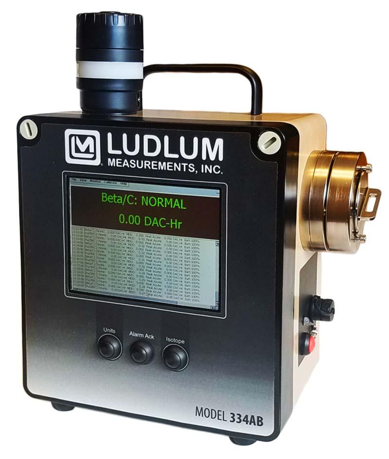
10 Parts of the Model 334AB The Model 334AB consists of a fiberglass NEMA enclosure containing the SabreMCA electronics, battery and pump assemblies. A detector head, mounted to the right side of the case, contains the detector, preamp, and a filter holder. A light stack containing an audible alarm and red light is mounted to the top of the case. On the front, the Model 334AB contains a 5.5-inch touch-screen display. The display is most easily operated using a stylus. There are three buttons located below the touch-screen display which allow the user to toggle displayed units and isotope/channel, as well as an alarm acknowledge to silence and clear an alarm. On the right side below the detector head, there is a red power button, mini USB port, charging port and LED charging indicator, along with other ports needed for additional options. The Model 334AB includes an annunciator (alarm light/audible alarm) that is used when radiological alarms have been enabled. The annunciator has an adjustable volume setting. To adjust the volume, twist the top of the light stack, mechanically limiting its sound. To make the alarm louder, twist counterclockwise, allowing more sound from the horn. To make the alarm softer, twist the ring clockwise. In addition to the Model 334AB itself, the package it comes in contains an AC Adapter for charging the Model 334AB, a USB sync cable for exchanging data with a PC, a flow calibration aid, and a CD with software, certificates and training videos. Ludlum Measurements, Inc 2 December 2016
11 Understanding the Detector Head The Model 334AB has an integrated head that houses the detector. Optionally, it can house an additional guard detector for use in gamma background subtraction. Also, an In-Line Sample Head on an umbilical is available as an option. The detector head has several components that function together to be able to accurately detect the decay of radioactive particulates. The following is a brief summary: The detector is mounted to the side of the case inside a cavity, covered by a removable filter holder. The detector is delicate and should not be touched. The filter holder captures a 37mm filter with a threaded ring and mounts it inside the cavity, opposite the detector face. Between the detector face and the filter is a small gap of air that creates a flow path by extending circularly around the outside of the Detector Head. Air-borne particulates are suctioned into the Head via the air flow path, through the radial gap and are captured on the filter. The air flow continues past the filter, through the side holes, and into the case, where it is pumped out the bottom of the case. As particulates on the filter decay, the emitted alpha and/or beta particles hit the face of the detector and are recorded by the 334AB. Below is a series of diagrams that illustrates the progression of particulates and their decay. Ludlum Measurements, Inc 3 December 2016

12 Turning the Unit On A red switch located on the side of unit below the detector head turns on the power to the Model 334AB. After pressing the switch, the Model 334AB application will execute automatically. In general, a cold startup takes about 20 seconds. If it does not, the unit needs to be charged. Charging the Batteries Upon receiving a new unit, or when preparing a unit that has been shut down for a length of time, the Lithium-Ion battery must be fully charged. The battery can be charged by plugging the AC Adapter into a wall socket (115 VAC only) and plugging the power connector into the jack at the lower right side of the case. A Red/Green LED next to the connector indicates the charging state. When the LED is Red, the battery is being charged. When the LED is Green, the battery is charged and the charger may be removed. The charging time is approximately 3 hours. Complete Battery Discharge The Model 334AB has persistent registry settings that are saved in non-volatile flash memory thus keeping your program configuration settings intact if the battery is fully discharged. Also the Model 334AB application will be stored on a non-volatile SD card and will be restored once power is returned to the unit. So after the battery is fully discharged, all that is needed is to reconnect the unit to AC power and allow the battery to charge again. Depending on user settings, measurement records can either be stored on the SD card or on the My Documents folder. The default save location for log data is the My Documents folder, but in the event of a full battery discharge, these files would not be restored. Only files saved on the SD card can withstand a full battery discharge. Ludlum Measurements, Inc 4 December 2016


13 NOTE: Two charge cycles may be required for completely discharged batteries. Simply unplug and re-plug the power connector to start a new charge cycle. Power Button Functions The unit can be put into standby/sleep mode at any time during operation by pressing the power button. This ends all measurement processes, and turns off the pump and LCD. From sleep mode, the unit can be turned back on by pressing the power button again. For a full shutdown, press and hold the power button for 5 seconds. Be aware that this clears all measurement files in My Documents. In most cases, standby mode will be sufficient for most storage situations, and a charge of at least 50% should last the weekend. Full shutdown should be used for shipping or storage longer than several days. Starting the Program Under normal circumstances, the Model 334AB program will start automatically when the instrument is turned on, and remain in the program when the instrument is put to sleep and resumed. If there is a need to exit the program, it can be restarted from the desktop screen by double tapping the icon labeled Ludlum 334A using a stylus. Once the Model 334AB program is running, you will not be able to perform any other Windows CE operations like running other applications or changing display or network settings. To close the Model 334AB program tap File Close in the menu. Response Check The Response Check dialog is the first screen to be displayed after starting the Model 334AB program. The Response Check function will be covered later in this manual. For now, and until the Model 334AB is fully calibrated, tap the Skip button to bypass the Response Check or wait for 60 seconds for it to time out and then automatically continue. The home screen is then displayed. Ludlum Measurements, Inc 5 December 2016
14 Understanding the Display The basic display for the Model 334AB includes a Menu bar across the top, a Meter in the upper half of the screen and a Log entry in the lower half that toggles to view the current Spectrum. Menu Meter Log & Spectrum The Menu bar across the top of the screen provides access to the various settings and other information. They will appear differently depending on whether the password security feature is enabled. These menu items and their sub-menus will be covered in detail in other sections of the manual. The Meter displays the status and current data of the selected channel. In Beta-Only mode, only the beta and flow channels are displayed. In Alpha-Beta mode, it will display up to two alpha isotopes of interest and the short-lived radon daughters: Po-212, Po-214 and Po-218. The first line indicates the channel name with a suffix character to denote the type of reading, Acute (/A) or Chronic (/C), which is followed by a status, usually normal. The second line reports the current reading with the default unit. The Log entry display in the lower half of the screen shows the readings for the beta channel and alpha channels (optional), logged once a minute. Each standard log entry lists the chronic reading, the minimum detectable dose, the highest acute reading of that minute and the battery charge level. Other log entries are listed as they occur. Possible log entry status conditions are high alarm, low battery, flow rate failure, and other types of failures. The Spectrum can also be viewed in the lower portion of the screen, in addition to the log entry display, by tapping View Spectrum in the menu. The spectrum is displayed as a bar graph made up of the detected counts. Each count is assigned to one of 256 channels, increasing in energy along the non-visible X-axis. The Y-axis is a non-visible scale of counts that compresses to fit the entire spectrum in view. The red line represents the mathematical peak-fit curve that best matches the actual data. After several hours, three peaks will have formed on the right end of the spectrum and illustrate the counts associated with the three radon daughters. The meter displays the various isotopes and variables being measured. To toggle the current channel displayed, press the Channel button on the front of the unit. Repeated presses of the Channel button will cycle through the channels, switching between acute and chronic info before cycling to the next channel. Ludlum Measurements, Inc 6 December 2016
15 Changing the units displayed on the meter is done by hitting the Units button. This will toggle through units of activity and concentration (e.g. pci, cps, DAC-Hr, DAC). Each Channel has its own set of four units, while Flow and Gamma (optional) channels only have one unit each. How to Change the Filter After a Model 334AB has been monitoring for some time, the filter will become laden with dust and need to be replaced. Do this regularly; either by a specific schedule or when the flow rate declines and indicates Lo Flow (see section 3 on configurations). Replace the filter by removing the Filter Holder from the Detector Head, unscrewing the ring that captures the filter, and discarding or storing the filter appropriately. With the Back or Pump Side facing up, lay a new filter into the retaining ring and screw it back onto the Filter Holder. It should be snug enough to create a good seal with the O-rings. The back side should not be visible. Insert the Filter Holder back into the Detector Head cavity. From the menu, tap Monitor Reset Instrument to start a new count that does not include data from the old filter. Always reset the instrument after a filter change. Password Security The Model 334AB supports password security to prevent unauthorized users from changing the instrument configuration or calibration. By default, password security is turned off and all menus and functions are accessible. Password security may be enabled by checking Use Password Security from the File Properties menu. The Properties dialog is explained fully in Section 3: Configuration. Tap File Login from the menu to enter a password. Security Levels and Default Passwords: Logged Out User level allows access to the View menu item only Configuration level allows access to the View and Monitor menu items- config Calibration level allows full access to the View, Monitor and Calibrate menu items - calib Ludlum Measurements, Inc 7 December 2016


16 When logged in to the calibration level, the user is able to change the password(s) by tapping File Security Options to open the Authorization Level Passwords dialog. Be sure to record the new passwords in a safe place, as a forgotten password would require factory support to reset. Setting the Clock The Model 334AB is configured with a real-time clock which can be manually set or set automatically when connected via the USB port to a PC. The unit is factory calibrated to the correct customer time-zone before shipment. Whenever the battery and external power are disconnected from the main processor board during maintenance or repair, the clock will be reset to a default date. The Model 334AB program will sense this condition and allow the operator to manually set the clock during startup. To access the Date/Time properties dialog, double tap the time displayed in the lower right of the desktop. Ludlum Measurements, Inc 8 December 2016
17 SECTION 2 Calibration To maintain accurate measurements of dose and concentration, the unit must be calibrated periodically. Separate Alpha, Beta, and Flow calibrations are required for complete calibration. The purpose of alpha calibration is to insure that the peak-fitting algorithm knows where in the spectrum to expect the radon peaks. This ensures that proper radon background subtraction of the beta channel is performed. If the radon peaks appear too far from the expected locations, the peak-fitting algorithm will fail (POOR FIT status) and the unit will fail to alarm properly. The purpose of beta calibration is to ensure that the unit is measuring beta counts with the highest possible counting efficiency and low noise. Flow calibration is also important, as it determines if the Model 334AB is converting the pump current into the measured flow rate correctly. The calibration functions are accessed from the Calibration item on the main menu. Two types of calibrations can be performed on the Model 334AB. The first is called the Automatic Alpha calibration, which is a source calibration check. The other type of calibration is the Advanced calibration, which separates Alpha Energy, Alpha Efficiency and Beta Efficiency calibrations. Advanced Calibrations should be performed in this order, for both Beta-only and Alpha/Beta configurations: Alpha Energy Alpha Efficiency Beta Efficiency NOTE: Ludlum instruments are shipped already calibrated at the factory elevation of 5100 feet. Because they are elevation-dependent, both the Advanced Alpha Energy Calibration and Flow Calibration should be repeated at the customer site, for elevation differences of greater than 1000 feet, before the instrument is put into service. For new instruments, the customer should perform the advanced alpha energy and efficiency calibrations so that subsequent Automatic Alpha calibrations start from an accurate calibration baseline. Ludlum Measurements, Inc 9 December 2016
18 Calibration Overview When performing a manual calibration, the Alpha energy calibration step should always be performed before doing the alpha or beta efficiency calibrations. Advanced Alpha Energy Calibration consists of: Roughing in the position of the IoI peak with a source and adjusting the Offset Running the unit for +8 hours to accumulate a radon daughter spectrum Adjusting the peak marker positions of the Po-212, Po-214 and Po-218 radon daughter peaks along with the IoI peak marker. Advanced Alpha Efficiency Calibration consists of: Determining the counting efficiency to an alpha calibration source. Automatic Alpha Calibration consists of: Using the Isotope of Interest source to run an Efficiency Calibration Adjusting the peak marker for the IoI, which automatically adjusts the radon peaks Advanced Beta Efficiency Calibration consists of: Adjusting threshold potentiometers on a PCB inside the case for desired beta background level Acquiring a 10 minute background count for confirmation of settings Performing an efficiency calibration using a beta source. Flow Calibration consists of: Setting up an apparatus: Flow Calibration Aid, Flowmeter, & flow restriction device Defining 3 flow rates and entering the measured flow of each in LPM Validating the calibration with a 4 th flow rate, which gives an error percentage Calibration Expiration The Model 334AB program keeps track of the last time the alpha energy calibration was performed and will indicate that the unit is out of service if one of two conditions is met: A user-defined number of days since the last calibration have elapsed. Default is 365 days. The unit has exceeded the user-defined number of hours of run-time since the last calibration. Default is 8800 hours. When the calibration expires, the Model 334AB display will indicate OUT OF CAL. Ludlum Measurements, Inc 10 December 2016
 in diameter, have an active area restricted to the center 25 mm (1 ), and have an activity between 10,000 and 150,000 DPM.")
19 Source Requirements When performing any of the alpha and beta calibrations, a calibration source is used. Calibration sources should be electroplated on stainless steel disks no larger than 32 mm (1.26 ) in diameter, have an active area restricted to the center 25 mm (1 ), and have an activity between 10,000 and 150,000 DPM. NOTE: It is vital that the surface of the source is the same distance from the detector face as the surface of a filter would be. Poor-fitting source holders and sources that are too large or have a bezel would severely impact calibration. Calibration source holders may be ordered which fit the Model 334AB detector head and hold a 32mm source in the proper position for repeatable calibration geometry. It is also very important that the alpha calibration source matches the first isotope-of-interest (IoI 1) and the beta calibration source is similar in energy to the expected betas. Set Source Parameters For the alpha calibrations, the source type and activity must first be entered in the Calibration Isotope Parameters dialog by tapping Calibrate Set Alpha Source Entering the calibration isotope parameters separately enables the user to use a source isotope for the Automatic and Advanced Alpha Calibration and for the Response Check. Enter parameters and tap ok. Ludlum Measurements, Inc 11 December 2016
20 Calibration Instructions Alpha Energy Calibration To begin the alpha energy calibration, tap Calibrate Advanced Alpha Energy on the menu. The Alpha Energy Calibration dialog will be displayed showing the alpha energy calibration settings and a window of the spectrum, if it has been collected. The horizontal axis represents the possible energies, assigned to channels 0 to 255. The vertical scale accumulates counts in each channel and adjusts automatically to display the highest peak. Several vertical red lines are scattered along the alpha spectrum. The number of lines depends on the operating configuration of the Model 334AB. These lines indicate the position of the alpha peaks, and can be adjusted by dragging to match up with the peak location. The numbers at the top of each red line correspond to the channel number of the peak location. There are either zero, one or two alpha isotopes-of-interest, plus the Po-218, Po-214 and Po-212 radon-progeny peaks. In radon mode, a peak marker for Po-210 will also appear. If operating in Alpha-Beta mode, the lower reference line(s) on the spectrum coincide with the isotope(s)-of-interest. In Beta-only mode, only the 3 markers for the radon peaks are used. Configuration Settings The four fields on the top of the Alpha Energy dialog each correspond to one of the four configuration settings. The parameters for Gain, Threshold, Offset and Scale, determine the view of the alpha spectrum on the display. These configuration settings affect the location, width, spacing and offset of alpha peaks on the spectrum. The threshold, gain and scale should not have to be adjusted from factory settings, so only the offset may have to be changed based on the elevation of the instrument s location. The instrument is initially calibrated at 5100 feet. Alpha calibration is altitude dependent, so it is important that this is taken note of. The values for these four settings are stored permanently on the SabreMCA board, and changing any of them will save the new values over the old values. The user can read the following descriptions of the four parameters to get a better understanding of how the Alpha spectrum is displayed: Ludlum Measurements, Inc 12 December 2016
21 Gain (Range 1 to 31) This value controls the amplitude of pulses coming from the detector. Increasing the gain broadens isotope peaks, shifts them to the right, and spreads individual peaks further apart. As the Gain is increased, the peak(s) can be shifted completely off the right end of the spectrum display. Shifting to the next Scale will bring the peaks back into view on the spectrum. Also, as Gain is increased, the noise amplitude will increase proportionally, requiring a compensating increase in Threshold level. Gain should not normally be changed from the factory setting. Threshold (Range 1 to 31) This value controls the amplitude threshold that pulses must exceed to be measured. It should be set just above the level where the amplifier noise is first observed. Default Threshold is 9. Less than 9 disables the threshold. Offset (Range 0 to 255, in 8 channel increments) Increases in this value shift the 256-channel spectrum the defined number of channels to the left. The Offset is elevation-dependent and may need to be adjusted by the user in increments of 8. Offset is related to the Scale setting by controlling the 256-channel window on the scaled discriminator output. If the Scale is zero, the Offset will allow the output of any consecutive 256 channels, from discriminator channel 1 to channel 512. If the Scale is one, Offset will allow the display of any 512-channels over the 1024-channel discriminator range (binned down to 256 spectrum channels). If the Scale is two, the Offset has no effect and the entire 1024-channel discriminator output is compressed 4::1 to the 256-channel spectrum. Default Offset is set at factory calibration. Scale (Range 0 to 2) This value controls the binning or compression of the channel discriminator output into the 256-channel spectrum value. A value of zero results in no compression. A value of one is a 2::1 compression, binning 512 channels of the discriminator output into 256 spectrum channels. A value of two is a 4::1 compression, binning all 1024 channels of the discriminator output into 256 spectrum channels. Default Scale is 1 and should not normally be changed. Performing the Calibration Alpha energy calibration consists of aligning the peak markers with the corresponding isotope peaks in the spectrum. This is most efficient when a mid-energy (e.g. 5 MeV) source is verified to appear near channel 120, then resetting the spectrum and accumulating a radon spectrum overnight. Once the spectrum is positioned, the peak markers may be aligned. Observe the following steps for more detail. Consideration for Radon Mode The Model 334A can be factory-configured to operate in Radon Mode where the radon/thoron progeny are used to determine the PAEC (potential alpha energy concentration) exposure to the worker in milli-working levels (mwl). There will be no marker for the PAEC channel. The PAEC reading will replace the first isotope-of-interest, but a second IoI can be enabled, usually Mixed Uranium, which will have a marker. In radon mode, a peak marker will also appear for Po210. The energy of the Po210 peak is at 5.3 MeV, left of the Po218 peak. Ludlum Measurements, Inc 13 December 2016

22 Roughing in the Source Peak Place a mid-energy alpha source such as Am-241 in the sampling head and verify that the peak appears just below mid spectrum (near channel 120) and that the peak tail narrows to near zero at the left end of the spectrum. Adjust the Offset if needed, tapping reset spectrum after each adjustment. This insures that the three radon progeny peaks should be visible after the overnight run. Collecting an Alpha Radon Spectrum Reset the spectrum, and then make sure a clean filter has been inserted into the detector head and leave the Alpha Energy Calibration window open on the screen before leaving the Model 334AB to collect the radon spectrum. Leave the Model 334AB operating in a high radon area for 8-12 hours so that a well-defined radon spectrum can be accumulated. NOTE: After a few hours, if the 3 peaks are not all visible, the Offset needs to be increased by 8, 16, or 24 channels to shift the peaks further left. Click Reset Spectrum and run the unit again for several hours to accumulate another spectrum. Lining Up the Daughter Radon Peaks After all three peaks of the Alpha radon spectrum are clearly visible on the screen; the radon daughter peaks can be calibrated. Line up each of the red lines with their respective peak location by dragging the lines across the screen until they line up with the top of the peak. Another number will appear while the line is being dragged that indicates the number of counts per channel. Release the line on the channel with the highest counts. Ludlum Measurements, Inc 14 December 2016
23 Calibrating the Isotope of Interest (Optional) For units with the Alpha measurement option, the isotope(s)-of-interest also needs to be energy calibrated at this point. Remove the filter and leave the detector exposed. Using an appropriate source holder, to provide repeatable geometry, place the desired isotope-of-interest calibration source in the detector recess so that the source face is the same distance from the detector as a filter would be. Leave it there as a well-defined peak becomes visible on the screen. Remove the source before the peak becomes too large. Then, drag the remaining red line and align it with the peak location. Repeat this procedure if necessary with a second source corresponding to the alternate isotope-of-interest. Alternatively, use the Isotope of Interest Channel Calculator (found on the CD) to determine the peak location, without a source. Finalizing the Energy Calibration Once all of the peaks have been successfully lined up, tap the Reset button on the screen to clear the spectrum. Then replace the filter and close up the detector head. Tap the OK button, then tap Yes when prompted to save the settings and update the calibration date. Ludlum Measurements, Inc 15 December 2016

.")
24 Alpha Efficiency Calibration Alpha Efficiency calibration is not an elevation-dependent function. So for brand new units, factory calibration of Alpha Efficiency will be sufficient and this calibration can be skipped. Performing the Alpha Efficiency Calibration is used to determine the detector counting efficiency to the isotope-of-interest energy. This efficiency is used to produce accurate exposure and concentrations in units of measure meaningful to the user (e.g. DAC-h and mwl). It also makes sure that the Model 334AB is counting at an acceptable rate. To begin the Alpha Efficiency Calibration, select Calibrate Advanced Alpha Efficiency from the menu. Indicate the source activity in DPM, which should be written on the source, its container or certification sheet. Remove the filter holder and insert the calibration source holder in the detector recess. In addition, be aware that the detector must only be exposed to 25mm of active area either by using a 25mm source or by masking the additional area. Once the source activity has been entered and the source inserted, tap Start Calibration. The calibration will run for two minutes or until it has reached 10,000 counts, whichever is longer. After the calibration has completed, it will report the efficiency. The Alpha 4-Pi Efficiency should be around 30 percent. Typical efficiencies are 25-33% for Am-241, and 18-24% for Th-230. If the efficiency falls outside these parameters, either Repeat Calibration or call a Ludlum Technician for assistance. If the efficiency is acceptable, remove the source from the detector, place the filter back, and close up the detector head. Tap OK to close the dialog and save the new efficiency setting. Ludlum Measurements, Inc 16 December 2016


25 Automatic Alpha Calibration Customers should first perform the Advanced Calibrations, using the same calibration isotope source, before running Automatic calibrations. The automatic alpha energy calibration is designed to make regular alpha energy calibration quick, easy, and accurate. This calibration mode will adjust the offset parameter in the MCA and the energy channels of the radon isotopes to compensate for a shift of the spectrum due to electronic drift over time, or from significant temperature and pressure changes. To start the Automatic calibration tap Calibrate Automatic Alpha on the menu. Open up the detector head and remove the filter. Insert the source defined as the Alpha Source and tap Start Calibration. The calibration routine will calculate the alpha efficiency and display the efficiency results. The Alpha 4-Pi Efficiency should be around 30 percent. An efficiency percent outside of the expected range would indicate a discrepancy in the process or possibly with the unit. Repeat Efficiency or call a Ludlum Technician for assistance. Hit Next to go to the Calibrate Energy step. In the Calibrate Energy step, the peak fitting process occurs. This is where the red lines that correspond to the isotopes energy levels (peak channels) line up with the peaks displayed by the spectrum. The peak should appear with the calibration source still inserted in the detector head. If the peak channel does not line up, then the user needs to drag the red marker to the height of the peak. Once the peak channel is lined up, select Finish. If you elect to save the new settings, then the offset, radon peaks and second IoI peak will be adjusted an equal amount to compensate for the new attenuation. For most users doing a re-calibration using the same isotopes, these Automatic Alpha steps will be sufficient to calibrate the instrument. Instruments that exhibit POOR_FIT status or erratic readings should be recalibrated using the advanced calibration procedure. Ludlum Measurements, Inc 17 December 2016
.")
26 Beta Efficiency Calibration Performing the Beta Efficiency Calibration is necessary to determine the detector counting efficiency to the beta particulates on the filter. This efficiency is used to produce accurate exposure and concentrations in meaningful units (e.g. DAC-h and pci). It also makes sure that the Model 334AB is subtracting beta background counts at an acceptable rate. This calibration procedure is characterized by manually adjusting several potentiometers (variable resistors) mounted to the Beta PCB within the unit in order to calibrate the thresholds of each setting. Summary The following section will describe the steps necessary for setting the beta background by adjusting manual potentiometers. Each time a pot is adjusted, reset the count and wait for at least a minute to get an accurate count. Longer count times improve the statistical accuracy of the background reading as the displayed value is an average since the Reset button was pressed. You will repeat the following process of adjusting the pots and checking the Gross CPM until the desired count rate is reached. Then the next steps will be a 10 minute background count to confirm the settings. Last, the actual beta efficiency calibration will be performed. Reset the Background Count Go to the menu at the top of the screen and tap on Calibrate Advanced Beta Efficiency First, remove the filter and return the filter holder to the radial head, so that the Model 334AB is operating under normal flow conditions but without a filter. Tap the Beta Reset button so the display reads zero for a brief period, then begins its cumulative average. In this dialog, you will watch for changes to the beta Gross CPM, as adjustments to the potentiometers are made. The acceptable target background for optimum sensitivity is between 5 and 15 CPM. If after a few minutes, the Gross CPM is reading within that tolerance, skip the threshold adjustment steps and proceed to Verifying the Background Count. Ludlum Measurements, Inc 18 December 2016


27 Understanding the Background Thresholds The Model 334AB has four settings that control the beta detection sensitivity; they are controlled by four manually adjustable potentiometers inside the unit. R18 controls the high voltage used to bias the beta-sensitive detector. It allows the bias voltage to be adjusted between zero and 90 volts DC. Default is 70 V. R15 controls the lower threshold for the beta channel. This setting defines the threshold below which, pulses will not be counted. It should be set above the electrical noise baseline so as to maximize the beta signal-to-noise ratio. Acceptable sensitivity is usually achieved at a background between 5 15 CPM. R11 controls the threshold for the alpha channel. This setting defines the threshold between beta pulses and the larger alpha pulses. Any pulse exceeding this threshold will not be counted as a beta pulse. R32 controls the lower threshold for the guard channel. This setting defines the threshold between noise and gamma pulses and should be set to produce equal beta and guard detector responses to a gamma source. For example, it should be set to produce approximately the same count rate in both the beta and guard detector channels when exposed to a 10 µci gamma source (Cs-137) about one foot away, in front of the unit. Ludlum Measurements, Inc 19 December 2016
28 Adjusting the Beta Background Threshold NOTE: Please use appropriate ESD precautions to protect the unit from electrostatic discharge while the case is open during this process. Only trained personnel should perform this particular step of calibration. To get to the potentiometers, first unscrew the large plastic screws that secure the Model 334AB lid to the base and open up the case. The 2-Channel board is located in the top half of the Model 334AB base, with the potentiometers mounted on blue casings. Turning the potentiometers counterclockwise lowers the threshold and increases the counts per minute, while turning it clockwise raises the threshold and lowers the counts per minute. 1. Adjust the beta threshold (R15) so that the beta background count is 5 10 CPM. Use a very small screw-driver to adjust the bias potentiometer appropriately. 2. To observe the effects of adjusting the potentiometers, check the Beta Net CPM in the dialog box. Remember to press the reset button and wait at least one minute each time after adjusting. Leave the lid closed, but not screwed shut, during these measurements. 3. If behavior is erratic, check that the alpha threshold (R11) is at max thresh: clockwise. 4. If necessary, check that the detector bias (R18) is set to 70V. A detector bias of 50 to 90V is necessary for beta and gamma pulses to be produced by the detector. Adjusting the Gamma Background Threshold If the optional guard detector was included with your Model 334AB, then the guard background thresholds must also be set. Setting the guard threshold follows a similar procedure to setting the beta threshold. The count rate for the guard detector is displayed below the beta information. If the Model 334AB does not include the guard detector, then the count rate in the guard field will be zero counts per minute. The emphasis in setting the Guard Threshold is so that both guard and beta detectors respond to gamma background the same way. 5. Remove the filter, and then re-insert the filter holder with the ring but no filter. 6. Place a 10µCi (Cs-137) gamma source in front of (or behind) the unit about 12 inches away. This arrangement orients the source equidistant from both detectors. 7. Adjust the gamma threshold (R32) until the Guard count rate reads approximately the same as the Beta rate. Press the Reset button and wait 1 minute each time it is adjusted. Ludlum Measurements, Inc 20 December 2016
.")

29 Verifying the Background Count After achieving the desired background count rate(s), close up the Model 334AB. Tap Start Calibration, and the ten minute background check will begin. Once the background check is complete, it should produce a gross count rate within the 5-15 CPM range (if it does not, reopen the case and adjust the threshold as before). If a guard detector is installed, the guard background will also be determined and should also be in the 5-15 CPM range. Beta Efficiency Calibration After the background check is complete, begin the Beta Efficiency calibration by removing the filter holder from the radial head. Insert the calibration source into the detector recess. A beta source with a 25 mm (1 ) active area and at least 10,000 DPM should be used for the calibration. Enter the DPM source activity in the in the Source DPM field. If the source activity is reported in CPM, double the activity to account for beta backscatter, and enter that amount. Then tap Start Efficiency. The calibration will run for two minutes or until it has reached 10,000 counts, whichever is longer. Ludlum Measurements, Inc 21 December 2016
30 After the beta source count is complete, the Model 334AB will display the 4-Pi beta efficiency. The efficiency should be in the range of 6-20%, depending on the beta isotope energy. Higher energy beta isotopes (e.g. Sr/Y-90) produce efficiencies between 14-20%. An efficiency result outside of this range could be the result of an improperly set Beta or Guard threshold or an activity calculation error. If the efficiency falls outside these parameters, either Repeat Calibration or call a Ludlum Technician for assistance. If the efficiency is acceptable, remove the source from the detector, place the filter back, and close up the detector head. Tap OK to close the dialog and save the new efficiency setting. Response Check After either an Alpha or Beta Calibration has been performed, it is good to double check the calibration by running a Response Check. The response check can also be done at any time if the user wants to verify the unit is still in calibration. Follow the detailed instruction is Section 4 of this manual. Ludlum Measurements, Inc 22 December 2016

31 Flow Calibration The Model 334AB sample flow rate is estimated by monitoring the pump s electrical current. Flow calibration is necessary to insure that the Model 334AB program is correctly monitoring and converting the pump current into a flow. This relationship is not linear. As a result, a three-point flow calibration is used, with validation at a fourth flow rate. Flow Calibration is also an elevation-dependent function, and thus is required before putting the unit into service. Setting Up the Apparatus To begin the flow calibration, first gather the appropriate equipment for the procedure: Volumetric Digital Flowmeter (a Rotameter will work as well) Tygon tubing Flow restriction device (a clamp or needle valve) Flow Calibration Aid (included with Model 334AB, 1 per order) Create the testing apparatus by attaching the flow restriction device to the Tygon tubing on the side of the digital flowmeter opposite the unit, and attaching the flow calibration aid to the end of the Tygon tubing on the other side. Place the Flow Calibration Aid over the entire detector head, with the edge pressed all the way up against the case, like pictured. NOTE: Ensure that the variable flow restriction does not completely cut off the airflow to the pump. The pump is not designed to operate at zero flow and the high vacuum could damage the pump diaphragm. Do not allow the pump to run below 3LPM for more than a few minutes. Ludlum Measurements, Inc 23 December 2016


32 Performing the Calibration To begin, make sure the pump is ON (Monitor Pump On in the menu). Then, open up the flow calibration dialogue under Calibrate Flow The flow calibration is a three-point calibration, meaning it takes measurements at three different flow rates (low, medium, and wide open), and the program then uses those measurements to create an equation for a curve. It can then use the curve to calculate the pump s flow later on. A fourth flow rate is used to validate this curve, and reports the measured difference in an error percentage. The flow calibration dialog instructs the user throughout the process. NOTE: Any flow rate will work as long as the measured flow entered is the same as what is reported by the flowmeter. So if the Flowmeter reports 4.11 then the Measured Flow is entered at 4.11 even if the instructions ask for 4.0 LPM. The first step in the flow calibration is to reduce the flow rate by adjusting the flow restriction device to a low flow rate, at about 4 LPM. Enter the actual value from the flowmeter in the dialogue under Measured Flow. Then hit Start Calibration. Each step in the process will take about 30 seconds as indicated by the progress bar. Repeat this process for the medium flow rate, at about 5 LPM. Ludlum Measurements, Inc 24 December 2016


33 In the third step, adjust the flow restriction device until it is completely open, providing maximum flow. Again, input the LPM indicated on the flowmeter into the Measured Flow box on the screen. Continue with the same process as before. The last step is to validate the calibration. Adjust the flow restriction device until the flowmeter reads approximately 80% of max flow, or near 5.5 LPM. Input the Measured Flow, and then tap Validate. The validation step will check to make sure the formula calculated by interpolation is correct, and will produce an error percentage, which should be less than 5 percent, and is usually less than 1 percent. The flow calibration is now completed and this example shows 0.4% error, which is acceptable. Tap Close and save the calibration settings. Remove the flow calibration aid from the detector head, which may be difficult because of the suction created. It is recommended that the pump is turned off temporarily and possibly a second set of hands are used for leverage. Lastly, replace the filter and close up the detector head. Ludlum Measurements, Inc 25 December 2016

34 SECTION 3 Configuration The Model 334AB program provides several dialogs to allow configuration of the instrument operation. These dialogs are accessed through the File and Monitor menus. Each dialog and its settings are described below. Instrument Properties This dialog controls the operation of the of the user interface aspects of the program. Tap the File Properties menu item to access the Instrument Properties dialog. Voice Update Frequency Voice output is not implemented in the Model 334AB, so the settings are disabled. Ludlum Measurements, Inc 26 December 2016
35 Meter Update Frequency The Meter Update Frequency settings control the regularity with which the meter is updated. While the instrument is in a Normal status condition, the meter will update at the interval specified by the Normal setting. Units are in seconds. Default is 1 second. Any Abnormal condition will cause meter updates to occur at the more frequent interval specified by the Abnormal setting. Default is 1 second. User Options The Use password security option provides a method of disabling certain calibration and configuration functions unless the user has entered an acceptable password. Two password levels are supported: calibration and configuration. The calibration level allows access to all menus and features, while the configuration level provides access only to alarm settings and other non-calibration-related functions. Default passwords are: calib for calibration, and config for configuration. The Alarm Silence by menu only check box, when checked, required that alarms are acknowledged from the Monitor Acknowledge Alarm menu selection. When unchecked, alarms may be silenced either from the menu, or by pressing the Alarm Ack button on the face of the Model 334AB. When paired with the Use Password Security option, the user must have at least a config-level password in order to acknowledge and silence the alarm. Default is unchecked. The Disable buttons when logged out setting prevents the use of all three front panel buttons by unauthorized users (not just Alarm Ack). It is only available when Use Password Security is checked. Default is unchecked. The Skip Response Check on startup option allows startup and use of the unit without performing a response check. When this setting is active, the Response Check is only performed from a menu command. When unchecked, after a startup, the user is prompted to perform a Response Check. Default is unchecked. The Backlight incremental scroll bar controls the level of light provided to the LCD screen. To achieve the 8-hr battery runtime, the unit should be set to the lowest setting. Instrument Options The Instrument Options dialog controls the functional behavior of the Model 334AB. Access the dialog from the menu by tapping Monitor Instrument Options The dialog consists of at least four tabs of settings and information: General, Logging, Beta, Flow, and optionally Isotope 1 and 2, RadNet, ASCII. Ludlum Measurements, Inc 27 December 2016

36 General Tab Serial No This is a non-editable field that identifies the factory-defined serial number of the Model 334AB. Default: Factory set Window Settings Acute Window This setting defines the count time used to determine the Acute Dose, NetCps and Activity. It should be set to provide the fastest response to high concentration spikes of a pre-determined level. Shorter times mean higher minimumdetectable levels but do not necessarily mean faster response times. Some experimentation may be required to achieve a desired alarm level and response time. Default is 120 Seconds. Chronic Window This setting define the count time used to determine the Chronic Dose, Concentration, NetCps and Activity. Longer times provide better sensitivity and lengthen the dose integration time. Default is 240 Minutes. Calibration Expiration Settings Calibration expires This non-editable item displays the latest date on which the Model 334AB calibration will expire. The expiration could occur sooner if the maximum runtime hours are exceeded. Calibrations are valid for XXX days This field sets the maximum number of days between calibrations. Default is 365 days. But not more than YYY runtime hours This field sets the maximum number of hours of Model 334AB runtime between calibrations. Default is 8800 hours. Ludlum Measurements, Inc 28 December 2016

37 Logging Tab The Logging Interval settings control the data logging behavior of the Model 334AB. Several types of log files are created on the Model 334AB during operation. See Section 6: Retrieving and Analyzing the Data, for more information on the log files. Log Acute readings every This setting controls the frequency in seconds that Acute readings are written to a log file (Pu239_AcuteYYYYMMDD.txt). Each filename created has the format NameYYYYMMDD.txt, where YYYY represents the year, MM represents the month, and DD represents the creation day. Default is 15 Seconds. Log Spectrums This setting controls whether spectrum snapshots are written to a log file (SpectrumYYYYMMDD.txt). If the setting is checked, the Log Spectrums frequency field will be enabled. Default is Spectrum Logging is ON. Log Spectrums every This setting defines the frequency in minutes that spectrums are time stamped and logged. Default is 10 Minutes. Log data destination This selection defines the location where Model 334AB data will be saved. My Documents folder This setting saves log files in the My Documents folder. This is a volatile folder that will be erased in the event of a complete battery discharge or loss of battery power. Default is the My Documents folder. SD Card this setting causes log data to be saved to the non-volatile SD memory card in the Model 334AB. Note: data saved to the SD Card is accessible from an attached PC/laptop, but data is not automatically synchronized with the PC as are files in the My Documents folder. Ludlum Measurements, Inc 29 December 2016

38 Beta Tab This page defines the parameters concerning the measurement of and alarming on the net beta reading. It supports both a fixed beta background, and the use of a guard detector for real-time subtraction of gamma interference. DAC Constant This setting defines the conversion constant to convert from Pico- Curies per liter to DAC, defined by 10CFR835. Note that the constant uses units of Pico-Curies per liter to avoid the need for scientific notation. Default is 1 DAC = 100 pci/liter Alarm Configuration Enable Alarms This checkbox controls the checking for and annunciation of alarms for this isotope of interest. Left unchecked, all alarming will be disabled and no alarm checking will be performed! Default is checked, Alarming performed. Latch Alarms This checkbox configures whether alarms are latching or non-latching. Non-latching alarms (un-checked) will clear automatically once the reading drops below the alarm set point. Latching alarms (checked) must be acknowledged by the user before the alarm status will be cleared. Alarms must be cleared manually through the Monitor - Acknowledge Alarm menu item, or with the Alarm Ack button. Default is unchecked, Nonlatching. Alarm Settings This button calls up the alarm settings dialog to configure the alarm set points for beta. See the dialog description under Alarm Settings below. Background Subtraction Radon subtraction This setting controls whether counts due to beta-emitting radon progeny are subtracted from the beta reading. When set, the alpha activities of the radon/thoron progeny, determined by alpha spectroscopy, are used to estimate the beta Ludlum Measurements, Inc 30 December 2016

39 activities of the progeny. Counts proportional to the estimated beta activity are then subtracted from the gross beta rate to determine the net beta rate. Default is selected. Subtraction factor This parameter is multiplied by the calculated radon/thoron beta activity to produce the value subtracted from the gross beta rate. Because the beta counting efficiency is dependent on the beta energy, the radon/thoron betas will have a higher or lower efficiency than the beta calibration efficiency. Default is 1.0. Guard Detector Present This checkbox is selected if the Model 334AB is factory configured with a guard detector. It is not user-editable. Fixed Subtraction Factor [Displayed if Guard detector not installed] This setting controls what portion of the fixed beta background count rate is subtracted from the gross beta count rate. The fixed background rate is determined during the beta efficiency calibration. Default is 1.0. Gamma Subtraction factor [Displayed if Guard detector present] This parameter is multiplied by the Net Gamma activity to produce the value subtracted from the gross beta rate. Default is 1.0. Alarm Settings This dialog allows configuration of the acute and chronic alarm set points for dose and concentration alarms. Separate Alarm Settings dialogs are applied for Beta and each Isotope. Chronic Alarms Chronic Dose This setting determines the alarm set point for a chronic dose alarm. Default is 20 DAC-h. Chronic Concen. This setting determines the alarm set point for a chronic concentration alarm. Default is 1000 DAC. Ludlum Measurements, Inc 31 December 2016

40 Acute Alarms Dose (DAC-h) This setting determines the alarm set point for an acute dose alarm. Default is 80 DAC-h. Acceptable False Alarm Rate This setting defines the acceptable number of false alarms per year. The limit has an effect on the calculated minimum-detectable dose and concentration limits. Therefore, it has an effect on the dose and concentration sensitivities. The setting is used to determine the sigma factor which is multiplied by the standard deviation of the calculated dose and concentration to yield the minimum-detectable level. Allowing more false alarms will provide better alarm sensitivity at the expense of more frequent false alarms. Default is 10 false alarms per year. Isotope Tabs (with Alpha option) The Iso 1 and 2 tabs define the parameters concerning the primary and secondary isotopeof-interest measurements. By default, the first isotope of interest is Pu-239, however, this isotope may be changed to support the measurement of other alpha-emitting isotopes. Note: The radon daughters (Po-218, Po-214 and Po-212) are always monitored, even in Beta-only configurations. They are used in the background subtraction algorithm and reported on the meter. Isotope This pull-down list provides for the selection of other isotopes of interest. This selection affects only the isotope of interest and not the measurement of radon daughters, which are always monitored. Default is Pu-239. Peak Channel (uneditable) This setting identifies the channel where the peak of the selected isotope-of-interest is expected by the peak-fit algorithm. Although it is not editable from this dialog page, it is set during the calibration procedure. Ludlum Measurements, Inc 32 December 2016

41 DAC Constant This setting defines the conversion constant to convert from Pico- Curies per liter to DAC, defined by 10CFR835. Note that the constant uses units of Pico-Curies per liter to avoid the need for scientific notation. Default is 1 DAC = pci/liter Alarm Configuration Enable Alarms This checkbox controls the checking for and annunciation of alarms for this isotope of interest. Left unchecked, all alarming will be disabled and no alarm checking will be performed! Default is checked, Alarming performed. Latch Alarms This checkbox configures whether alarms are latching or non-latching. Non-latching alarms (un-checked) will clear automatically once the reading drops below the alarm set point. Latching alarms (checked) must be acknowledged by the user before the alarm status will be cleared. Default is unchecked, Non-latching. Alarm Settings This button calls up the alarm settings dialog to configure the set points for the isotope-of-interest. See the dialog description under Alarm Settings above. Iso 2 Tab This page defines the parameters concerning the second isotope-of-interest measurements. By default, the isotope of interest is none, however, this isotope may be changed to support the measurement of other alpha-emitting isotopes. Ludlum Measurements, Inc 33 December 2016

42 Flow Tab This page defines the high, low, and failure limits for air flow measurement in liters per minute. It also offers a Fixed Flow setting for externally plumbed units. Low Limit This setting defines the limit in liters per minute below which the Model 334AB will indicate a LO FLOW status. A low flow status can indicate a loaded or wet filter. Default is 6.0 LPM High Limit This setting defines the limit in liters per minute above which the Model 334AB will indicate a HI FLOW status. A high flow status can indicate a missing filter, leaking or disconnected vacuum line. To achieve a missing filter limit, remove the filter, replace the filter holder, check the flow rate, and set just below this rate. Default is 7.5 LPM. Low Fail Limit This setting defines the limit in liters per minute below which the Model 334AB will indicate a FLOW FAIL status, go out of service, and will not alarm. A flow fail status can indicate a kinked or clogged vacuum line. Default is 4.5 LPM. Use Fixed Flow When checked, this setting is used for units with external pumps with no flow measurement capabilities. Default is Unchecked. Ludlum Measurements, Inc 34 December 2016

43 RadNet Tab (with WiFi option) This page contains the settings for RadNet Protocol broadcasts for Model 334AB units with the WiFi Option installed. This page will only appear for wireless-enabled instruments. Use WAN IP Address When checked, a specific WAN IP address can be entered. When unchecked, the unit broadcasts to the entire C-class subnet. Default is unchecked Broadcast Measurements This checkbox enables or disables the transmission of measurement packets to RadNet clients. Default is enabled and uneditable. Measurement Type List Box This list describes the options for measurement packet broadcasts. Allowable choices are Chronic and Acute data, Chronic Only, and Acute Only. Default is Chronic and Acute and is factory set to user specifications Broadcast Spectrums This checkbox enables or disables the transmission of Model 334AB spectrums to RadNet clients. Check the box to enable spectrum broadcasts. Spectrum Type List Box This list describes the options for spectrum packet broadcasts. Allowable choices are Chronic unless Acute Alarm, Chronic Only, and Acute Only. Default is Chronic unless Acute Alarm and is factory set to user specifications Port This field specifies the UDP Port number which RadNet packets are broadcast on. User editing of the port number is disabled. Default is Debug mode Checking this setting will insert wireless debug information into the status log. It can be of use by IT personnel when attempting to troubleshoot communications issues. Default is unchecked Ludlum Measurements, Inc 35 December 2016

44 ASCII Tab (with RS-232 or WiFi option) This page contains the settings for ASCII Communications Protocol broadcasts for Model 334AB units with either the RS-232 Option or the WiFi Option installed. The RS-232 option offers a DB-9 or RJ-9 connector on the side panel, while the WiFi option provides an internal antenna or broadcasting. RS-232 Enabled When checked, this setting transmits measurement packets via RS-232 using the ASCII Protocol. Default is checked if ordered COM This field specifies the Communications Port number of the PC that the RS-232 cable is connected to. Default is COM5. Baud This field specifies the bits per second with which ASCII packets are broadcast. Default is WiFi Enabled When checked, this setting transmits measurement packets wirelessly using the ASCII Protocol. Default is checked if ordered TCP This field specifies the TCP Port number which ASCII packets are broadcast on. Default is UDP This field specifies the UDP Port number which ASCII packets are broadcast on. Default is Enable Beta Data When checked, this setting includes beta data in the measurement packets. Default is checked Enable Alpha Data When checked, this setting includes alpha data in the measurement packets. If unit is Beta-only, this setting is disabled. Default is checked Ludlum Measurements, Inc 36 December 2016
45 SECTION 4 Starting a Dose Measurement Response Check Routine Before starting a dose measurement, the Model 334AB should be tested using the Response Check routine to make sure that it is operating properly and in calibration. The purpose of the Response Check is to verify the following: A consistent activity is reported from a source of known activity The detector and SabreMCA are functioning properly For beta response checks, that the noise/background is properly compensated for and the beta efficiency has not changed. For alpha response checks, that the source isotope is correctly identified, the peak area properly measured, and that the alpha efficiency has not changed. Source Requirements In both alpha and beta source checks, the source used should have an active (plated) diameter of at least 25mm (1-inch). If the active area is larger, the activity of the 25mm area must be known so that when masked to that size, the activity is accurate. The overall diameter of the source can be no larger than 32mm (1.26-inch). The sources also need to match the beta energy and/or the isotope-of-interest the Model 334AB is configured to measure. The activity for beta sources should take backscatter into account. It is suggested that the DPM activity be calculated from 2X the surface emission rate in CPM. Ludlum Measurements, Inc 37 December 2016

 This setting specifies an upper fail limit on the measured activity. Any reading above this value at the end of the test will cause the Response Check to fail.")
46 Running the Response Check After starting the Model 334AB program, the Response Check dialog is automatically initiated. It may also be initiated from the menu by tapping Monitor Response Check. There are four edit fields in the upper portion of the screen: Source This list box displays the applicable sources that can be used for the response check. The Beta choice is always available. If the user has specified an alpha calibration source, that isotope will also appear. For alpha-beta mode Model 334AB instruments, the primary isotope-of-interest will also be listed. High Limit (dpm) This setting specifies an upper fail limit on the measured activity. Any reading above this value at the end of the test will cause the Response Check to fail. The user should set this value to be approximately the source activity in dpm, plus 10%. Low Limit (dpm) This setting specifies a lower fail limit on the measured activity. Any reading below this value at the end of the test will cause the Response Check to fail. The user should set this value to be approximately the source activity in dpm, minus 10%. Count Time (sec) This setting defines the time window in seconds over which the activity will be averaged. The actual duration of the Response Check will be longer to account for stabilization of the reading. Set the High/Low Limits to reflect the desired tolerance and set the Count Time to produce a reading that will reliably fall within the limits. The tolerance of ±10% is only a suggested limit and actual tolerances may be varied based on customer procedures or preferences. Remove the filter holder, exposing the detector head, and place the source in the detector recess. The location and spacing of the source to the detector should be repeatable, and should produce geometry identical to the location and spacing of the filter. When the source is in position, tap the Start Count button to begin the test. A progress bar and Reading in dpm field provide visual feedback during the test. Ludlum Measurements, Inc 38 December 2016
47 When the test is complete, the final activity reading and results of the test are displayed with a Pass/Fail possibility. In the event of a Response Check: FAILED, it is up to the user to determine whether the instrument is still serviceable. As with any statistical test, given a mean and a set of limits, there is a finite probability that the test may fail, even though the instrument is operating normally. A reading slightly out of range may indicate only that the unit should be Response Checked again and the results compared to historical records. A reading significantly out of range is a warning that the instrument is not operational. Tap the Close button, or just wait for the dialog to time out after a minute of inactivity, to exit the Response Check routine. Another dialog will prompt you to remove the source, then install a clean filter, and reinsert the filter holder into the detector head. Normal Measurement Operation Once the Response Check is completed, the Model 334AB enters normal operation and begins monitoring for beta activity and, optionally, for the alpha isotope(s)-of-interest. The instrument will begin measuring dose and concentration immediately and can alarm on a measurable activity. Minimum-Detectable Levels & Window Times The minimum-detectable levels of concentration and dose will be elevated until the Acute and Chronic Window times have elapsed, defaulted to 120sec and 240min respectively. Until the full window times have elapsed, the Model 334AB is using incomplete spectrum accumulations to calculate the dose and concentration and has elevated statistical fluctuations of the results. This means that for the first 240 seconds (using twice the default Acute Window time), the Acute MDD will be elevated, and, for the first eight hours (again, using twice the default Chronic Window time), the Chronic MDC and MDD will be elevated. For the unit to alarm, it is required that the dose or concentration must exceed the minimum-detectable level and the alarm set point. In the beginning, the minimumdetectable levels will likely be above the alarm set points, but will gradually decline and plateau below the alarm set points. Display: Meter/Spectrum/Log The Model 334AB display components, the Meter, Log and Spectrum, were described in greater detail in Section 1. What follows is a brief summary. The meter displays readings on a continual basis during operation. The default meter display is the Chronic Dose reading for the beta channel. In alpha-beta mode, the Dose, Concentration, activity and net count rate for the isotope(s)-of-interest as well as the radon daughters, Po-212, Po-214, Po-218 may be displayed as well through the use of the buttons on the front panel of the Model 334AB. Ludlum Measurements, Inc 39 December 2016

48 To select between Acute and Chronic readings and the flow channel, press the Channel button to cycle through the various readings. Acute readings are denoted by the suffix /A, and chronic readings by the suffix /C. In alpha-beta mode, alpha channels are similar. For example, the Pu- 239 Acute reading is labeled, Pu239/A and the Pu-239 Chronic reading by Pu239/C. Press the Units button to cycle through DAC-h, DAC, NetCPS, pci/l, and other units. The Model 334AB spectrum may be displayed from the menu by tapping View Spectrum. In this view, the 256-channel spectrum is displayed instead of the log entries. Return to the log entry view by tapping View Log. In the event that a dose or concentration reading exceeds alarm limits, the Model 334AB will alarm visually and audibly, automatically display the channel of the chronic or acute reading that caused the alarm, and the status will be changed to High Alarm. Operational Duration For lengthy or continuous air monitoring, it is recommended that the unit be run using the AC adapter. When operating off the battery, the Model 334AB will run, under normal conditions, for approximately eight hours before the battery level forces a shutdown. The age of the battery, as well as the use of wireless reporting capability, will affect the run time. Note: In order to preserve program and log data, the Model 334AB will automatically shut down when the battery life reaches 15%. Ludlum Measurements, Inc 40 December 2016
49 SECTION 5 Measurement Calculations Acute & Chronic Moving-Windows In order to calculate a concentration, the counts for each counting channel are saved along with the flow rate and volume in a history array, so that the increase in counts over time can be used to determine the net count rate. For each counting channel, two different time intervals are used to determine concentrations and are referred to as the acute and chronic window times. These are sometimes referred to as the fast window and slow window. The peak counts based on the history values over one and two window times are used to determine the net count rates. For instance, if the window time is 60 seconds, then the net count rates for the last minute and also the minute previous, are calculated. For long-lived isotopes, the increase in net count rates over the two intervals is proportional to the concentration. The Acute window time offers a very quick response to measurement data, sacrificing some accuracy in the process. The Chronic window time provides a very accurate dose reading, but must take place over a substantial period of time. Ludlum Measurements, Inc 41 December 2016
50 Beta Measurement Calculations Because the counting efficiency for betas is dependent on the maximum isotope energy, the Model 334AB must be calibrated for the beta isotope-of-interest in order for the concentration and dose calculations to be accurate. Typically, it is calibrated to SrY-90. Beta Concentration Calculations To determine the net beta count rate, one or two forms of background subtraction are applied: fixed (or guard detector) compensation for gamma interference; and optional radon compensation. Net beta calculation without guard detector: Net beta calculation with guard detector: Where, B Gross = Gross beta counts G Bkg = Guard background B Bkg = Beta background F R = Radon subtraction factor F G = Fixed(Guard) subtraction factor Po 212 = Po 212 counts G Gross = Gross guard counts Po 214 = Po 214 counts Acute Net counts are stored in the acute history buffer every second, while Chronic Net counts are stored in the chronic history buffer every minute. The concentration equation used for the acute and chronic beta calculation is: Concentration T WA Vol Net1 Net K Cal Eff 0 Sample DAC Where, T WA = Actual window time in seconds Eff = Beta efficiency (4-Pi) Net 0 = Net counts: T 2T WA to T T WA Vol Sample = Air volume since filter change Net 1 Cal = Net counts: T T WA to T = Calibration constant K DAC = DAC conversion factor (equals 1 if DAC not used) Ludlum Measurements, Inc 42 December 2016
51 The T WA actual window time in seconds may be shorter than the user-defined window time. When a new spectrum is begun, following a spectrum reset or a filter change, a window time equal to the elapsed time, is used so that a best guess concentration value can be calculated. This actual window time will increase until it is equal to the user-defined time. This occurs when the user-defined window time has elapsed since the filter change or spectrum reset. After this point, the user-defined time is used. Beta Dose Calculation The Model 334AB program calculates dose according to the activity collected on the filter. Because the Model 334AB is typically used to continuously monitor the air in a facility, the concept of worker dose is dependent upon the portion of time the worker spends in the facility in comparison to the time the Model 334AB filter has been accumulating activity. For instance, if a unit has been sampling air at 1 CFM for 40 hours, and the activity of SrY- 90 is 150 dpm, the worker dose is dependent on how many of the 40 hours the worker spent inside the room being monitored. Therefore, the determination of worker dose must be accomplished administratively by noting the dose readings when the worker enters and leaves the area and calculating the increase in dose. Dose T WA K DAC Net1 Cal Eff Flow Sample 60 Where, T WA = Actual window time in seconds Eff = Beta efficiency (4-Pi) Net 1 = Net counts from T T WA to T Flow Sample = Flow rate Cal = Calibration constant K DAC = DAC conversion factor (equals one if DAC not used) Ludlum Measurements, Inc 43 December 2016
52 Alpha Measurement Calculations For alpha-beta mode configurations, the curve fit function produces coefficients for each isotope that correspond to the counts under the peak. Like the beta channel behavior, alpha channels use a history array, so that the increase in counts over time can be used to determine the net count rate. The peak counts based on the history values over one and two window times are used to determine the net count rates. For long-lived isotopes, the difference in net count rates over the two intervals is proportional to the concentration. Once the change in net count rate is known, the calibration constant and flow volume are used to derive the concentration in the specified measurement units. An additional term is included in the concentration calculation to account for the expected count rate losses due to activity that has decayed off during the last interval. For longer halflived isotopes the term Net 0 λ goes to zero. However, this term is very important for the proper treatment of the short-lived radon daughters. It should be noted that in situations where the counts under a peak are changing very slowly or not at all, slight variations may occur in the determination of the net count rate, which can result in small negative concentrations. These effects are minimized by the use of the two different evaluation intervals, with a longer interval providing greater precision in low-level measurements. Alpha Concentration Calculation The concentration equation used for the acute and chronic alpha calculation is: Concentration Net Net 1 0 / T WA Net 0 Vol Sample Yield K Cal Eff DAC Where, T WA = Actual window time in seconds Yield = Isotope Alpha yield Net 0 Net 1 Cal Eff = Net counts: T 2T WA to T T WA = Net counts: T T WA to T = Calibration constant = Detector efficiency (4-Pi) Vol Sample = Air volume since filter change K DAC = DAC conversion factor (equals one if DAC not used) ln 2 Lambda = decay constant, T½ where, T ½ = isotope half-life The flow measurement is used to accurately determine the volume of air collected on the filter paper during the count time. Ludlum Measurements, Inc 44 December 2016
53 Alpha Dose Calculation Like beta worker dose, the determination of alpha worker dose must be accomplished administratively by noting the dose readings when the worker enters and leaves the area and calculating the increase in dose. Activity Net Yield T Cal Eff 1 WA Dose Activity K DAC Flow Sample 60 Where, T WA = Actual window time in seconds Yield = Isotope Alpha yield Net 1 = Net counts from T T WA to T Flow Sample = Flow rate Cal Eff = Calibration constant = Alpha efficiency K DAC = DAC conversion factor (equals one if DAC not used) Minimum Detectable Measurement Calculations Uncertainties in Peak Counts In most ROI-based Alpha-CAM s, the minimum detectible concentration is based on the statistical uncertainty of the background counts that fall within the region, in combination with the uncertainty of any counts in excess of the background. In the Model 334AB, the minimum detectible concentration (MDC) is not directly related to the spectrum counts, but to the uncertainty in the peak fit. An examination of the peak area variances confirms that when the counts due to an interfering isotope greatly outnumber the counts due to the isotope of interest, the variance of the isotope of interest increases. Likewise, when there are very few interfering counts from other isotopes, the variance begins to approach a value equal to the peak area counts. When spectrum counts are zero, there is still a minimum variance of the peak areas. This minimum variance affects the minimum detectable levels of dose, concentration and activity. At the start of operation, the program calculates and saves the minimum variance for the Isotope of Interest for use later in the calculation of the minimum detectable levels. Uncertainties in Flow Rate The measurement of the flow rate and volume has a statistical variance that contributes to the MDC and MDD. This statistical variance is calculated by the program and applied in the MDC and MDD calculations. Ludlum Measurements, Inc 45 December 2016
54 Calculation of the Variance of Peak Counts The variances returned from the curve fit routine represent the uncertainties on the peak counts for each isotope during the last peak-fitting. The limit of detectability variance used is a combination of the fit variance with the previously saved zero-counts variance. Var LD K VarZero Variance 2 0 Where, K is the Sigma Factor a multiplier based on the False Alarm setting and the number of alarm determinations per year. Calculation of the Minimum Detectable Activity - MDA MDA T WA VarLD Cal Eff Calculation of the Minimum Detectable Concentration - MDC MDC Var LD Variance T WA Net Net Volume 1 0 K DAC T WA 0 Net Variance Error VOL 2 Concentration Calculation of Minimum Detectable Dose - MDD MDD MDA Activity 2 Error Flow Flow Sample 2 Dose K DAC Where, Variance 0 = Peak area variance for previous T WA Variance 1 = Peak area variance for most recent T WA Radon Mode Considerations The Model 334AB may be configured to operate as a radon progeny monitor, measuring and alarming on PAEC (potential alpha energy concentration) levels of milli-working Levels (mwl), and dose estimates in mwl-h. Alternatively, if configured for SI units, the instrument will display radon concentration in µj/m³ and dose estimates in µj-h/m³. The PAEC reading is treated as the primary isotope-of-interest and the chronic PAEC dose is shown as the default reading on the instrument (i.e. PAEC/C). Ludlum Measurements, Inc 46 December 2016
55 The PAEC is based on the individual radon decay product concentrations as measured off the filter. The beta-decay product Pb-214 is estimated from the concentrations of Po-218 and Po- 214 before its contribution to the PAEC can be added. The thoron contributions from Po-212 and Bi-212 are also included in the PAEC result and, when Bi-212 is present, the 6.0 MeV peak counts are corrected for known contributions from Bi-212 before the ultimate energy yield of MeV of Po-218 are summed. While its contribution is not included in the PAEC result, the Model 334AB does monitor for and report the concentration and dose estimate from Po-210. Ludlum Measurements, Inc 47 December 2016
56 SECTION 6 Retrieving & Analyzing the Data The log files stored on the Model 334AB may be retrieved and analyzed on a PC, laptop or workstation. The data can be imported into a spreadsheet or database and saved for future use. NOTE: This operation can be performed while the Model 334AB program is running, but it is sometimes preferable to end the dose measurement. Ending a Dose Measurement After a dose measurement period is complete, exit the Model 334AB program by tapping the File Close menu item. The program will terminate and close any open log data files. This should be unnecessary for continuous sampling mode operation. Note that if password security is enabled, the user will be required to log in before the File Close menu item will be accessible. PC Syncing Software To access the data on the Model 334AB, the user must install ActiveSync software from Microsoft and then connect the Model 334AB using the supplied USB cable. The latest version of ActiveSync can be found online on Microsoft.com as a free download. Computers running Windows 7 or Windows 8 come with software to automatically connect with the Model 334AB, called Windows Mobile Device Center, and do not require the ActiveSync software. Ludlum Measurements, Inc 48 December 2016


57 Connecting to a PC To connect to your Model 334AB, plug the USB sync cable from the computer to the mini-usb connection on the side of the unit. If the unit is turned on, the Model 334AB should automatically connect with the computer. Once connected, the Model 334AB will appear under Computer in the File Explorer. Your computer may categorize it as a camera, phone or portable device. A dialog will automatically pop up that requests to establish a permanent partnership. Click Set up your device and follow the process. Be sure to disable all options except Files, because we do not want tasks, contacts and appointments to be shared between the PC to the Model 334AB. If no automatic dialog pops up, double click the device icon in the File Explorer to open the files. Ludlum Measurements, Inc 49 December 2016
 and includes all the Model 334AB log files.")
58 Syncing Log Files ActiveSync or Windows Mobile Device Center Once connected to the Model 334AB, the program window is displayed on the PC and file synchronization will occur. When a partnership is created, a folder is created on the PC in the My Documents folder or desktop with a name corresponding to the Model 334AB name (e.g. M334AB_303 My Documents) and includes all the Model 334AB log files. Files will continue to sync each time the unit is plugged in to the PC. File Explorer Depending on where the log files are being stored, you may have to check both My Documents on the main drive (labeled / ) and the SD card. The files will be displayed there. You may select any or all of the log files and manually copy them to a more permanent storage location on the PC. The files can then be opened, imported into a spreadsheet or printed. Each log file contains time stamps in the name of the file. They are formatted with YYYY being the year, MM being the month, and DD being the day of the file creation. Each file begins with a header line describing the individual fields. Each subsequent entry in the log files is stamped with the time and date of its creation. The list below describes the files and their contents: Beta_Acute_YYYYMMDD.txt This text file contains the log of acute beta readings archived during the Model 334AB dose measurement period. New acute log files are started daily at midnight. Beta_Chronic_YYYYMMDD.txt This text file contains the log of chronic beta readings archived during the Model 334AB dose measurement period. New chronic log files are started weekly on Sunday morning at midnight. Ludlum Measurements, Inc 50 December 2016
59 Pu239_Acute_YYYYMMDD.txt Implemented in alpha-beta mode, this text file contains the log of acute readings archived during the Model 334AB dose measurement period. Note: the file name may be different if Pu-239 is not defined as the isotope-ofinterest. New acute log files are started daily at midnight. Pu239_Chronic_YYYYMMDD.txt Implemented in alpha-beta mode, this text file contains the log of chronic readings archived during the Model 334AB dose measurement period. Again, the file name may be different if Pu-239 is not defined as an isotope-of-interest. New chronic log files are started weekly on Sunday morning at midnight. StatusLog_YYYYMMDD.txt This text file contains a copy of the readings and status changes logged to the Model 334AB display during dose measurement. It includes a listing of any alarm and the time at which it occurred, along with chronic and peak acute readings. A new status log files is started daily at midnight. Spectrum_YYYYMMDD.txt These text files contain chronic spectrum snapshots at fixed (user-defined) intervals during the dose measurement period. Part of the filename is a timestamp indicating the year(yyyy), month(mm), and day(dd) into the dose measurement when the spectrum was archived. Each line in the file contains a set of peak-fit coefficients, a 255-channel spectrum of raw counts, and a 255-channel spectrum of the cumulative peak fit. A new spectrum log file is started weekly on Sunday morning at midnight. EnergyCalSpectrum.csv This comma-separated-variable format text file contains the last spectrum from the Energy Calibration if it was saved. Files with the.csv extension can be opened directly from Microsoft Excel. Once the Model 334AB log data has been retrieved, you may disconnect the USB cable from the computer to the unit. Disconnecting the USB cable will not affect the operation of the unit nor the files copied or synced. Graphing data in Excel Manually Data can be imported in Microsoft Excel and then manually graphed by following these instructions. Alternatively, the data can be graphed using the Excel templates on your CD, as described in the next section. Open a blank spreadsheet and select the Data tab - Get External Data From Text Find the beta chronic log file in the folder you synced or copied it to earlier and open it Proceed through the Text Import Wizard with these selections: Delimited Comma (not Tab) Date MDY Finish OK (=$A$1) The data can now be graphed as desired Save the spreadsheet to preserve the link to the imported data, for refresh later Ludlum Measurements, Inc 51 December 2016


60 Graphing data in Excel with Templates The best method for viewing data is to use the Excel templates to graph the data. The customer CD included with your order contains example Excel spreadsheets for displaying Chronic/Acute data and spectrums. They can easily be customized for your needs. There is one main template provided, but your CD may contain more templates depending on the configuration of your unit. Spectrum Chart Open the Excel document labeled Data Charting Template. You should see a chart of the spectrum, showing mostly the Radon daughter counts in three peaks on the right side. This first chart in the template is called the Spectrum Animate Chart which displays the spectrum data over time in a moving graph. You can press the Animate button to play the time-lapse graph of the previously imported spectrum data. Follow the instructions to refresh the template with new data from your unit. Spectrum Animate Chart Click the Spectrum Data tab to view the raw data. Click on any cell to begin To import new data, select the Data menu tab and click Refresh (not Refresh All) Ludlum Measurements, Inc 52 December 2016

61 Navigate to the folder where you synced or copied the log files to earlier. Find the spectrum file labeled Spectrum_YYYYMMDD and import it. Click back to the Spectrum Chart tab and press the Animate button again to view the new spectrum time-lapse. Double click the Y-axis and adjust as needed to keep the whole spectrum in view. A Fixed Maximum value of 500 or 1000 is recommended. Auto is difficult to interpret. Chronic & Acute Charts The subsequent tabs are charts for the Acute and Chronic windows for both Alpha and Beta data. You can follow the same instructions as above to refresh the template with new data from your unit. These points are supplemental and may help with instruction: Because there are several data tabs, you can either select Refresh All from the first data tab and choose the files one after the other in order, or select Refresh from each tab and choose one file at a time. When formatting the Y-axis, the whole chart does not need to be in view, as the minimum detectable line will likely be too high in the beginning to achieve good readability of the rest. The chart is best read when the typical readings are within the bottom fifth of the chart. See the example chart below for typical appearance. Once formatted, leave the axis set for better comparisons between data files. The X-axis may also need to be formatted for different dose measurement lengths. The length in time is automatic but the major unit needs to be fixed. For 1 hour increments use , for 2 hours use , for 4 hours use , and for 8 hours use Ludlum Measurements, Inc 53 December 2016
LUDLUM MODEL ALPHA, BETA, GAMMA HAND DETECTOR. June 2016 Serial Number and Succeeding Serial Numbers
 LUDLUM MODEL 44-25 ALPHA, BETA, GAMMA HAND DETECTOR June 2016 Serial Number 155835 and Succeeding Serial Numbers LUDLUM MODEL 44-25 ALPHA, BETA, GAMMA HAND DETECTOR June 2016 Serial Number 155835 and
LUDLUM MODEL 44-2 GAMMA SCINTILLATOR. February 2018 Serial Number PR and Succeeding Serial Numbers
 LUDLUM MODEL 44-2 GAMMA SCINTILLATOR February 2018 Serial Number PR361009 and Succeeding Serial Numbers LUDLUM MODEL 44-2 GAMMA SCINTILLATOR February 2018 Serial Number PR361009 and Succeeding Serial
MODEL AND MODEL GAS PROPORTIONAL DETECTORS. December 2016 Serial No and Succeeding Serial Numbers
 MODEL 43-37 AND MODEL 43-37-1 GAS PROPORTIONAL DETECTORS Serial No. 086152 and Succeeding Serial Numbers MODEL 43-37 AND MODEL 43-37-1 GAS PROPORTIONAL DETECTORS Serial No. 086152 and Succeeding Serial
LUDLUM MODEL AND LUDLUM MODEL ALPHA, BETA, & GAMMA DETECTORS
 LUDLUM MODEL 44-9-18 AND LUDLUM MODEL 44-9-19 ALPHA, BETA, & GAMMA DETECTORS January 2018 Serial Number PR254331 and Succeeding Serial Numbers LUDLUM MODEL 44-9-18 AND LUDLUM MODEL 44-9-19 ALPHA, BETA,
LUDLUM MODEL 44-3 LOW ENERGY GAMMA SCINTILLATOR. May 2018 Serial Number PR and Succeeding Serial Numbers
 LUDLUM MODEL 44-3 LOW ENERGY GAMMA SCINTILLATOR May 2018 Serial Number PR134823 and Succeeding Serial Numbers LUDLUM MODEL 44-3 LOW ENERGY GAMMA SCINTILLATOR May 2018 Serial Number PR134823 and Succeeding
LUDLUM MODEL 44-7 Alpha, Beta, Gamma Detector. July 2012 Serial No. PR and succeeding Serial Numbers
 LUDLUM MODEL 44-7 Alpha, Beta, Gamma Detector July 2012 Serial No. PR090405 and succeeding Serial Numbers LUDLUM MODEL 44-7 Alpha, Beta, Gamma Detector July 2012 Serial No. PR090405 and succeeding Serial
LUDLUM MODEL and PANCAKE CLUSTER DETECTORS. June 2016
 LUDLUM MODEL 44-89 and 44-94 PANCAKE CLUSTER DETECTORS June 2016 LUDLUM MODEL 44-89 and 44-94 PANCAKE CLUSTER DETECTORS June 2016 STATEMENT OF WARRANTY Ludlum Measurements, Inc. warrants the products covered
LUDLUM MODEL 25 AND 25-1 PERSONAL RADIATION MONITOR USER S MANUAL. October 2014 Serial Number and Succeeding Serial Numbers
 LUDLUM MODEL 25 AND 25-1 PERSONAL RADIATION MONITOR USER S MANUAL October 2014 Serial Number 25000100 and Succeeding Serial Numbers LUDLUM MODEL 25 AND 25-1 PERSONAL RADIATION MONITOR USER S MANUAL October
MODEL 23 AND 23-1 ELECTRONIC PERSONAL DOSIMETER. August 2017
 MODEL 23 AND 23-1 ELECTRONIC PERSONAL DOSIMETER August 2017 MODEL 23 AND 23-1 ELECTRONIC PERSONAL DOSIMETER August 2017 ii STATEMENT OF WARRANTY Ludlum Measurements, Inc. warrants the products covered
MODEL RWM RADIATION WASTE MONITOR LUDLUM MODEL RWM RADIATION WASTE MONITOR INSTALLATION MANUAL
 LUDLUM MODEL 3500-1000RWM RADIATION WASTE MONITOR INSTALLATION MANUAL August 2001 1 RECEIVING CONDITION EXAMINATION Be sure to verify that the shipping carton is received in good condition with no visible
LUDLUM MODEL 26 FRISKER USER S MANUAL. December 2016 Serial Number PF and Succeeding Serial Numbers
 LUDLUM MODEL 26 FRISKER USER S MANUAL December 2016 Serial Number PF001075 and Succeeding Serial Numbers LUDLUM MODEL 26 FRISKER USER S MANUAL December 2016 Serial Number PF001075 and Succeeding Serial
CO2 RESPONDER Portable Carbon Dioxide Detector QUICK REFERENCE GUIDE
 CO2 RESPONDER Portable Carbon Dioxide Detector QUICK REFERENCE GUIDE GasAlertMicro 5 IR from Refer to for more details. Manual provided on CD with unit at time of purchase 2 Table of Contents Getting Started.
PORTABLE ISOTOPE IDENTIFIER Search Tool / Sample Counting System
 FEATURES: HIGH GAMMA SENSITIVITY MULTI-CHANNEL ANALYZER (MCA) WORKS WITH VARIETY OF PROBES RADIONUCLIDE LIBRARY TAILORED TO CUSTOMER REQUEST SIMULTANEOUSLY MEASURES ; DISPLAYS; ALARMS 1-3 SEPARATE DETECTORS
A bright alpha numeric display and the simplified keypad (three buttons) allow the operation even under harsh conditions.
 allow the operation even under harsh conditions.") Personal Alpha/Beta Continuous Air Monitor (CAM) The pocamon (personal online continuous air monitor) monitors continuously the breathing air to detect airborne radioactive aerosols (LLRD). Typical application
Personal Alpha/Beta Continuous Air Monitor (CAM) The pocamon (personal online continuous air monitor) monitors continuously the breathing air to detect airborne radioactive aerosols (LLRD). Typical application
LUDLUM MODEL 35 SERIES DIGITAL SURVEY METER USER S MANUAL
 LUDLUM MODEL 35 SERIES DIGITAL SURVEY METER USER S MANUAL September 2016 LUDLUM MODEL 35 SERIES DIGITAL SURVEY METER USER S MANUAL September 2016 STATEMENT OF WARRANTY Ludlum Measurements, Inc. warrants
WinAMS AMS-4 Monitoring System for Windows
 Software Manual MA-WINAMS WinAMS AMS-4 Monitoring System for Windows REVISIONS SHEET: Rev. Rev. Dept. Name Rev. Cat. Explanation State resp. page *) 20.07.2010 RM&SI-SP Schmitt Transfer to Erlangen *)
LUDLUM MODEL 26-1 FRISKER USER S MANUAL. April 2017 Serial Number PF and Succeeding Serial Numbers
 LUDLUM MODEL 26-1 FRISKER USER S MANUAL April 2017 Serial Number PF002366 and Succeeding Serial Numbers LUDLUM MODEL 26-1 FRISKER USER S MANUAL April 2017 Serial Number PF002366 and Succeeding Serial Numbers
Falcon-II Next Generation, Air Quality Monitor CO2 & Temperature
 Critical Environment Technologies Canada Inc. Falcon-II Next Generation, Air Quality Monitor CO2 & Temperature OPERATION MANUAL REV: A JUNE-2-2008 #145, 7391 Vantage Way Delta, BC V4G 1M3 Canada Phone:
i.c³ User Guide For Helmer i.series Ultra-Low Freezers A/A
 i.c³ User Guide For Helmer i.series Ultra-Low Freezers 360175-A/A Document History Revision Date CO Supersession Revision Description A 18 APR 2014* 9275 n/a Initial release. * Date submitted or change
iminiplus PDF User Guide Version 2.0
 iminiplus PDF User Guide Version 2.0 Table of contents 1 Scope of this document... 3 2 Why PDF?... 3 3 Logger profile... 3 4 What you need to get started... 4 5 FDA 21 CFR Part 11 compliance... 5 6 How
Operations Manual TS400. Test Station for G450/G460 Gas Detector
 TS400 Test Station for G450/G460 Gas Detector Operations Manual 1194 Oak Valley Dr, Ste 20, Ann Arbor MI 48108 USA (800) 959-0329 (734) 769-0573 www.goodforgas.com GfG Products for Increased Safety Congratulations
AM-806. Waste/Door Radiation Monitor OPERATIONS MANUAL
 AM-806 Waste/Door Radiation Monitor OPERATIONS MANUAL Section Contents 1. SPECIFICATIONS 2. MAIN COMPONENTS 3. THEORY OF OPERATION 4. OPERATING INSTRUCTIONS 5. INSTALLATION Page 2 1.0 SPECIFICATIONS SENSITIVITY
User Manual. Digi-Sense TC9500 Advanced Multiparameter Temperature Controller with Thermocouple, Thermistor, and RTD Inputs
 User Manual Digi-Sense TC9500 Advanced Multiparameter Temperature Controller with Thermocouple, Thermistor, and RTD Inputs Models 89800-03 and 89800-04 THE STANDARD IN PRECISION MEASUREMENT Table of Contents
Table of Contents. Part I SAFETY MESSAGE TO INSTALLERS OF EMERGENCY WARNING EQUIPMENT 2 Part II Vehicle Operation 4. Part III Safety Messages 13
 Manual I SS2000 TouchScreen Installation Guide Table of Contents Foreword 0 Part I SAFETY MESSAGE TO INSTALLERS OF EMERGENCY WARNING EQUIPMENT 2 Part II Vehicle Operation 4 1 Installing the... SS2000 TouchScreen
LUDLUM MODEL 19A. Micro R Meter. May 2017 Serial No and Succeeding Serial Numbers
 LUDLUM MODEL 19A Micro R Meter May 2017 Serial No. 144020 and Succeeding Serial Numbers LUDLUM MODEL 19A Micro R Meter May 2017 Serial No. 144020 and Succeeding Serial Numbers Model 19A Micro R Meter
Dryer Master DM510 Commissioning Guide
 COMMISSIONING GUIDE Dryer Master DM510 Dryer Moisture Systems Inc. 640 Superior Drive Waterloo, Ontario Phone 519.725.4700 Fax 519.885.4300 USA & Canada Toll Free 1-888-318-0009 E-mail: info@dryermaster.com
User s Manual. TIGER S EYE E-Series Mark V Jockey. TIGERFLOW Systems, Inc Mint Way Dallas, Texas
 User s Manual TIGER S EYE E-Series Mark V Jockey TIGERFLOW Systems, Inc. 4034 Mint Way Dallas, Texas 75237 214-337-8780 www.tigerflow.com TABLE OF CONTENTS Introduction... 4 Sequence of Operation... 5
INSTALLATION. and INSTRUCTION MANUAL. for QUALITY AIR BREATHING SYSTEMS. Model ABM - 715
 INSTALLATION and INSTRUCTION MANUAL for QUALITY AIR BREATHING SYSTEMS Model ABM - 715 M A R T E C H S E R V I C E S C O M P A N Y P.O. Box 7079 OFFICE: 800-831-1525 Mazeppa, MN 55956 Fax : (507)843-4953
Monitoring Operator Guide. Access Control Manager Software Version
 Monitoring Operator Guide Access Control Manager Software Version 5.10.10 2018, Avigilon Corporation. All rights reserved. AVIGILON, the AVIGILON logo, ACCESS CONTROL MANAGER, ACM, ACM VERIFY AND TRUSTED
OVEN INDUSTRIES, INC.
 OVEN INDUSTRIES, INC. OPERATING MANUAL Model 5C7-252 TEMPERATURE CONTROLLER With PLC Inputs Introduction Thank you for purchasing our controller. The Model 5C7-252 is an exceptionally versatile unit and
Adaptive CyCLO Technical and HMI User Guide. CyCLO User Guide. Version th December 2017 REV
 CyCLO User Guide Version 2.00 19 th December 2017 REV 2.00 1 Contents 1. Hardware... 3 1.1. Introduction... 3 1.2. Electrical Specification... 3 1.3. Board Overview... 4 1.4. Electrical Installation...
HIn3550 Magnetic Field Monitor User's Manual
 HIn3550 Magnetic Field Monitor User's Manual Copyright 1993 by Holaday Industries, Inc. Manual #600053 10/97 $12.50 Revision Record Manual #600053 HIn3550 Magnetic Field Monitor Revision Description Date
LUDLUM MODEL 3276 SERIES FRISKER/AREA MONITOR USER S MANUAL. November 2017 Serial Number: and Succeeding Firmware: 49830n30 and Higher
 LUDLUM MODEL 3276 SERIES FRISKER/AREA MONITOR USER S MANUAL November 2017 Serial Number: 25009185 and Succeeding Firmware: 49830n30 and Higher LUDLUM MODEL 3276 SERIES FRISKER/AREA MONITOR USER S MANUAL
Ranger EXP RADIATION A L E R T
 RADIATION A L E R T TM Ranger EXP INTERNATIONAL S.E. International, Inc. P.O. Box 39, 436 Farm Rd. Summertown, TN 38483 USA 1.800.293.5759 1.931.964.3561 Fax: 1.931.964.3564 www.seintl.com radiationinfo@seintl.com
Portable Alpha/Beta Continuous Online Air Monitor (CAM)
") Aer 5000 Desktop Portable Alpha/Beta Continuous Online Air Monitor (CAM) The Aer5200 monitors the ambient air continuously to detect airborne radioactive aerosols (LLRD). Typical application fields are
Aer 5000 Desktop Portable Alpha/Beta Continuous Online Air Monitor (CAM) The Aer5200 monitors the ambient air continuously to detect airborne radioactive aerosols (LLRD). Typical application fields are
Contamination Meter Users Manual
 RDS-80 Contamination Meter U Users Manual Version 1.01 LAURUS Systems, Inc. - Ph: 410-465-5558 - Fax: 410-465-5257 - www.laurussystems.com NOTE This document and the information herewith are copyrighted
USB Multi Function Dataloggers. RHT30 Humidity/Temperature Datalogger. TH30 Dual Temperature Datalogger
 USER MANUAL USB Multi Function Dataloggers RHT30 Humidity/Temperature Datalogger TH30 Dual Temperature Datalogger Additional User Manual Translations available at www.extech.com Introduction Thank you
INSTALLATION INSTRUCTIONS
 TT-1343 5/06b INSTALLATION INSTRUCTIONS Original Issue Date: 8/03 Model: Automatic Transfer Switches Equipped with Series 1000 Programmable Controller Market: ATS Subject: Remote Annunciator Kits GM28938-KP1,
USER MANUAL. ITAG 4 / ITAG 4 Bio/ ITAG 4 TH DATA LOGGER. UM-ITAG REV.B 03/02/2016
 USER MANUAL EN ITAG 4 / ITAG 4 Bio/ ITAG 4 TH DATA LOGGER Updated@ 03/02/2016 CONTENTS Product Overview... 3 Logger... 3 LCD... 4 Technical Specifications... 5 TEMPCENTRE SOFTWARE... 6 How to download
Protégé Eclipse LED Keypad User Manual PRT-KLES
 Protégé Eclipse LED Keypad User Manual PRT-KLES The specifications and descriptions of products and services contained in this manual were correct at the time of printing. Integrated Control Technology
MGC Dock User s Manual
 User s Manual Contents Warnings Statements/Avertisseement... 3 READ FIRST BEFORE OPERATION... 3 Description... 4 Basic Operation... 5 Clip Dock Components... 5 LEDs... 5 User Operation... 6 Turning the
LUDLUM MODEL 44-9 ALPHA, BETA, GAMMA DETECTOR. February 2010 Serial Number PR and Succeeding Serial Numbers
 LUDLUM MODEL 44-9 ALPHA, BETA, GAMMA DETECTOR February 2010 Serial Number PR090405 and Succeeding Serial Numbers LUDLUM MODEL 44-9 ALPHA, BETA, GAMMA DETECTOR February 2010 Serial Number PR090405 and
USER MANUAL USB Multi-Function Datalogger Model RHT35
 USER MANUAL USB Multi-Function Datalogger Model RHT35 Additional User Manual Translations available at www.extech.com Introduction Thank you for selecting the Extech multi-function, easy-to-use, portable
User Manual. Humidity-Temperature Chart Recorder. Model RH520
 User Manual Humidity-Temperature Chart Recorder Model RH520 Introduction Congratulations on your purchase of the Extech RH520 Temperature + Humidity Chart Recorder. The RH520 measures and displays Temperature,
Alarm Client. Installation and User Guide. NEC NEC Corporation. May 2009 NDA-30364, Revision 9
 Alarm Client Installation and User Guide NEC NEC Corporation May 2009 NDA-30364, Revision 9 Liability Disclaimer NEC Corporation reserves the right to change the specifications, functions, or features,
Using the QRAE Plus personal multigas monitor
 Using the QRAE Plus personal multigas monitor Firmware v 1.10 QRAE Plus The Hazardous Environment Detection Company QRAE Plus features Turning on the QRAE Plus Recommended Daily Start-up Procedure User
User Manual. Digi-Sense TC9600 Advanced Multiparameter Temperature Controller with Thermocouple, Thermistor, and RTD Inputs
 User Manual Digi-Sense TC9600 Advanced Multiparameter Temperature Controller with Thermocouple, Thermistor, and RTD Inputs Models 89800-13 and 89800-14 THE STANDARD IN PRECISION MEASUREMENT Table of Contents
ENMET Corporation. PO Box 979 Ann Arbor, MI RECON. Manual. Manual Part Number MCN-410, 12/03/08
 PO Box 979 Ann Arbor, MI 48106-0979 RECON Manual Manual Part Number 80006-018 MCN-410, 12/03/08 Table of Contents 1.0 INTRODUCTION... 1 1.1 UNPACK... 1 1.2 CHECK ORDER... 1 1.3 SERIAL NUMBERS... 1 2.0
RAE Systems Systems. User Presentation. October Protection Through Detection
 RAE Systems Systems AreaRAE Inert User Presentation October 2009 www.raesystems.com AGENDA Overview & Features Basic Operation Turning the AreaRAE Inert monitor ON Warnings NORMAL & INERT Mode Displays
AUTOMATION. Operator s Manual RST Series Web Enabled Input Module. Rev. A2, 1/12
 AUTOMATION P R O D U C T S GROUP, INC. Operator s Manual RST-5000 Series Web Enabled Input Module Rev. A2, 1/12 Tel: 1/888/525-7300 Fax: 1/435/753-7490 www.apgsensors.com E-mail: sales@apgsensors.com RST-5000
GasScanner 1C. Single Channel Monitor. Operator s Manual. MINT-0278-XX Rev A
 GasScanner 1C Single Channel Monitor Operator s Manual MINT-0278-XX Rev A Product Warranty Matheson Tri-Gas, Inc., warrants gas alarm equipment sold by us to be free from defects in materials, workmanship,
MGC Dock User s Manual
 Operator s Manual Contents Warnings Statements/Avertisseement... 3 READ FIRST BEFORE OPERATION... 3 Basic Operation... 4 Clip Dock Components... 4 LEDs... 4 Operation... 5 Turning the Clip Dock On and
Operations Manual TS400. Test Station for G450/G460 Gas Detector
 TS400 Test Station for G450/G460 Gas Detector Operations Manual 1194 Oak Valley Dr, Ste 20, Ann Arbor MI 48108 USA (800) 959-0329 (734) 769-0573 www.gfg-inc.com GfG Products for Increased Safety Congratulations
INSTALLATION AND OPERATING INSTRUCTIONS FOR THE VEHICLE-MOUNTED RADIATION DETECTION SYSTEM
 INSTALLATION AND OPERATING INSTRUCTIONS FOR THE VEHICLE-MOUNTED RADIATION DETECTION SYSTEM D-tect Systems 11814 South Election Road, Suite 200 Draper, UT 84020 www.dtectsystems.com 1 Introduction The mini
MOVING FILTER AIR MONITOR ALPHA, BETA/GAMMA PARTICULATES
 FEATURES: MOVING AIR FILTER AIRBORNE ALPHA LESS RADON AND BETA/GAMMA PARTICULATES RUGGED, 100% DUTY CYCLE SETTABLE ALARM HIGH THROUGH-PUT UNATTENDED OPERATION 12 WEEKS PRINTED RECORD (Optional) 4 CHANNEL
Thermo Scientific Aerosol Monitor FHT 58 S Technical Specification ZT-221E
 Thermo Scientific Aerosol Monitor FHT 58 S Technical Specification ZT-221E Thermo Fisher Scientific Messtechnik GmbH Frauenauracher Straße 96 91056 Erlangen Germany www.thermo.com info.rmp.erlangen@thermofisher.com
Specification for On-Line UPS Battery Monitoring and Data Management System
 1 Scope This specification defines the minimum requirements for a predictive on-line Battery Monitoring BMDMS with test, analysis, and remote monitoring control capabilities. Unless noted otherwise, the
INSTALLATION. and INSTRUCTION MANUAL. for QUALITY AIR BREATHING SYSTEMS. Model ABM - 700
 INSTALLATION and INSTRUCTION MANUAL for QUALITY AIR BREATHING SYSTEMS Model ABM - 700 M A R T E C H S E R V I C E S C O M P A N Y P.O. Box 7079 OFFICE: 800-831-1525 Mazeppa, MN 55956 Fax : (507)843-4953
THX-DL Data Logger USER & INSTALLATION MANUAL V
 THX-DL Data Logger USER & INSTALLATION MANUAL V1.2012 www.thermomax-refrigeration.com Contents PRESENTATION Summary of Features 2 INSTALLATION Safety Precautions 4 THX Unit 4 Sensors 4 Alarm Relay 4 Power
Mark 25 Ultrapure Water Conductivity Analyzer
 Martek Instruments, Inc. Mark 25 Ultrapure Water Conductivity Analyzer Instruction Manual WARRANTY POLICY Unless otherwise stated, MARTEK INSTRUMENTS, INC. warrants this equipment to be free from defects
IMR IX176 Portable Gas Detector User Manual
 IMR Portable Gas Detector User Manual Read this manual carefully before using this device. (727) 328-2818 / (800) RING-IMR Fax: (727) 328-2826 www.imrusa.com Ver. 1.0A4 CONTENTS SERVICE GUIDELINES... 3
Trident User s Manual
 Labkotec Oy Myllyhaantie 6 33960 Pirkkala FINLAND Tel. +358 (0)29 006 260 18.05.2017 Fax +358 (0)29 006 1260 Internet: www.labkotec.fi 34 pages Trident Copyright 2017 Labkotec Oy 1/34 TABLE OF CONTENTS
Omniguard 4: Features
 OMNIGUARD 4 The clear choice for monitoring and documenting Vacuum and Pressure in a containment area. Ideal for Asbestos, Lead and Mold abatement and Clean Room monitoring. Omniguard 4: Features The Omniguard
Users Manual. LAURUS Systems, Inc. - Ph: Fax:
 Users Manual LAURUS Systems, Inc. - Ph: 410-465-5558 - Fax: 410-465-5257 - www.laurussystems.com Introduction The rad-d is a security and inspection system that detects emissions from radioactive material.
Centroid Snet 2. Battery Management Software. User Manual V1.1. Eagle Eye Power Solutions, LLC Keeping an Eye on Your Critical Power!
 Eagle Eye Power Solutions, LLC Keeping an Eye on Your Critical Power! Centroid Snet 2 Battery Management Software User Manual V1.1 www.eepowersolutions.com Tel: 1-877-805-3377 info@eepowersolutions.com
Sentry LIQUID LEVEL GAUGE MODEL 200 or 200C OWNER MANUAL REV 1.7 SEPT08 PAGE 1 OF 12
 PAGE 1 OF 12 TABLE OF CONTENTS PAGE 1. SAFETY PRECAUTIONS 1.1. Electrical shock 3 2. APPLICATION 3 3. INSTALLATION 3.1. Mount indoor alarm display 3.2. Mount the outdoor junction box 3.3. Install interconnecting
Simplex Panel Interface Guide
 Simplex Panel Interface Guide February 2016 SATEON Software Integrations Simplex Panel Interface Guide Issue 1.0, released February 2016 Disclaimer Copyright 2016, Grosvenor Technology. All rights reserved.
MPL3115A2 Sensor Toolbox User s Guide
 Freescale Semiconductor Document Number: MPL3115A2STUG User s Guide Rev. 0, 04/2012 MPL3115A2 Sensor Toolbox User s Guide 1 Introduction The Freescale DEMOSTBMPL3115A2 Sensor Toolbox provides the hardware
Beacon 800 Gas Monitor Operator s Manual
 Beacon 800 Gas Monitor Operator s Manual Part Number: 71-0037RK Revision: F Released: 4/18/17 www.rkiinstruments.com Product Warranty RKI Instruments, Inc. warrants gas alarm equipment sold by us to be
CASS9000 Standalone FingerPrint Door Access System. User Manual
 CASS9000 Standalone FingerPrint Door Access System User Manual CASS9000 COPYRIGHT Information furnished by Cass Technology Sdn. Bhd. is believed to be accurate and reliable. Cass Technology Sdn. Bhd. have
RK CO 2 Transmitter Operator s Manual
 65-2397RK CO 2 Transmitter Operator s Manual Part Number: 71-0185RK Revision: B Released: 7/18/14 RKI Instruments, Inc. www.rkiinstruments.com WARNING Read and understand this instruction manual before
WiFi Hints & Tips. Contents. WiFi Hints and Tips 1. Page No. Section No. Title
 WiFi Hints & Tips Contents Page No. Section No. Title Section.0 System Set-Up 3 Section. Sensor Set-Up 4-5 Section. Sensor Set-Up (Configuring Network) 6-9 Section.3 Sensor Set-Up (Configuring Settings)
Interscan Corporation. Instruction Manual Series Compact Portable Analyzer
 Interscan Corporation Instruction Manual 4000 Series Compact Portable Analyzer 1 2 INTERSCAN CORPORATION Simplified 4000 SERIES MANUAL TABLE OF CONTENTS SECTION TITLE PAGE 1.0 Equipment Description 4 2.0
ModSync Sequencing System Installation & Operation Manual. For use with Fulton Steam Boilers.
 ModSync Sequencing System Installation & Operation Manual For use with Fulton Steam Boilers. Revision 3.0 8/21/2008 - 2 - Table of Contents Introduction Page 4 Features Page 4 Sequence of Operation Page
Instruction manual MTL process alarm equipment. October 2016 CSM 725B rev 2 MTL RTK 725B. Configuration Software Manual
 Instruction manual MTL process alarm equipment October 2016 CSM 725B rev 2 MTL RTK 725B Configuration Software Manual SECTION 1 - INTRODUCTION... 5 Basic Requirements... 5 SECTION 2 - SOFTWARE INSTALLATION...
THL2. Temperature/Humidity USB Datalogger INSTRUCTION MANUAL
 The THL2 is compatible with computers using Windows 2000, XP, Vista, Windows 7 and Windows 8. INSTRUCTION MANUAL 2 THL2 1-800-547-5740 Fax: (503) 643-6322 www.ueitest.com email: info@ueitest.com Temperature/Humidity
Notice... 1 Trademarks... 1 US Patent Numbers... 1 Technical Services Contact Information... 2 Document Conventions... 2 Warranty...
 Table of Contents Preface 1 Notice... 1 Trademarks... 1 US Patent Numbers... 1 Technical Services Contact Information... 2 Document Conventions... 2 Warranty... 2 Chapter 1 Radius Overview 6 1.1 About
Section 8 System Operation
 Section 8 System Operation Operation of the control panel is simple. Menus guide you step-by-step through operations. This section of the manual is an overview of the operation menus. Please read this
Identify the following features and specifications for the ESP1
 LEARNING OBJECTIVES: 2.17.01 List the factors which affect an RCT's selection of a portable contamination monitoring instrument, and identify appropriate instruments for contamination monitoring. (Also
GG-2 2-CHANNEL GAS DETECTION CONTROL PANEL. Installation and Operation Manual
 GG-2 2-CHANNEL GAS DETECTION CONTROL PANEL Installation and Operation Manual 2 GG-2 Warning Use this product only in the manner described in this manual. If the equipment is used in a manner not specified
EasyLog Data Logger Series
 EasyLog Data Logger Series Overview EasyLog model EL-USB series products are a line of low cost, compact, battery-operated data loggers with built-in memory and USB interface. Each product in the line
725B Configuration Software Manual
 725B Configuration Software Manual REV DATED DESCRIPTION AUTHOR APPROVED 0 09-03-10 First Issue P.Cartmell Page 1 of 80 SECTION 1 - SOFTWARE INSTALLATION... 5 725B ConfigurationSoftware Installation...
ProStar 325 UV-Vis Detector
 Varian, Inc. 2700 Mitchell Drive Walnut Creek, CA 94598-1675/USA Star Chromatography Workstation Version 6 ProStar 325 UV-Vis Detector Control Software Varian, Inc. 2004 Printed in U.S.A. 03-914732-01:Rev.
Section 9 System Operation
 Section 9 System Operation Operation of the control panel is simple. Menus guide you step-by-step through operations. This section of the manual is an overview of the operation menus. Please read this
Dashboard for Windows V1.1.0
 User manual Dashboard for Windows V1.1.0 TBS Electronics BV De Factorij 46 1689 AL Zwaag The Netherlands www.tbs-electronics.com COPYRIGHT 2009 (rev1e) - 1 - TABLE OF CONTENTS 1. INTRODUCTION......................
Ion Gateway Cellular Gateway and Wireless Sensors
 Page 1 of 9 Account & Network Setup If this is your first time using the Ion Gateway online system site you will need to create a new account. If you have already created an account you can skip to the
status AW1 Plus WiFi Alarm System User Manual
 status AW1 Plus WiFi Alarm System User Manual Foreword Congratulations on your purchase of the AW1 Plus Alarm system. Before you commence installation we recommend that you unpack the product, familiarise
Carbon Monoxide Transmitter
 Introduction The CO Transmitter uses an electrochemical sensor to monitor the carbon monoxide level and outputs a field-selectable 4-20 ma or voltage signal. The voltage signal may also be set to 0-5 or
Refrigeration Controller Operator s Manual (HRC) PO Box 6183 Kennewick, WA
 PO Box 6183 Kennewick, WA") Refrigeration Controller Operator s Manual (HRC) PO Box 6183 Kennewick, WA 99336 www.jmcvr.com 1-509-586-9893 Table of Contents TABLE OF FIGURES...1 OVERVIEW OF THE HRC CAPABILITIES...2 INSTALLATION AND
Refrigeration Controller Operator s Manual (HRC) PO Box 6183 Kennewick, WA 99336 www.jmcvr.com 1-509-586-9893 Table of Contents TABLE OF FIGURES...1 OVERVIEW OF THE HRC CAPABILITIES...2 INSTALLATION AND
LogTag Recorders TRED30-16R. Temperature Recorder with Display and 30 Day Statistics Memory. Product User Guide
 LogTag Recorders TRED30-16R Temperature Recorder with Display and 30 Day Statistics Memory Product User Guide Document Release Version: 1.4 Published 1. March 2017 Copyright LogTag Recorders, 2004-2017
HOBO U14 Data Logger User Manual
 HOBO U14 Data Logger User Manual The U family of data loggers offers reliability and convenient monitoring for applications that require higher accuracy, better resolution, more memory, or USB connectivity
AGC 200 Advanced Gen-set Controller OPERATOR S MANUAL
 Advanced Gen-set Controller OPERATOR S MANUAL Display readings Push-button functions Alarm handling Log list Document no.: 4189340607A SW version 3.5X.X or later Table of contents 1. ABOUT THIS DOCUMENT...3
PowerLogic ION Setup Meter Configuration Software Configuration Guide
 PowerLogic ION Setup Meter Configuration Software Configuration Guide 70002-0293-03 12/2010 Conventions Used in this Manual This section describes the symbols and terminology used in this guide. Symbols
RAM GENE-1 ERK. Contamination & Radiation Meter. Operating Manual. Document #PRIR90N2.DOC Version 2.2 October 2009
 RAM GENE-1 ERK MK-Ι & MK-ΙΙ Contamination & Radiation Meter Operating Manual Document #PRIR90N2.DOC Version 2.2 October 2009 Version / Revision Log: RAM GENE-1 ERK/ Operating Manual Ver./Rev.# Date Revised
ANALOX 101 D2 PORTABLE OXYGEN MONITOR USER MANUAL
 ANALOX 101 D2 PORTABLE OXYGEN MONITOR USER MANUAL Analox Sensor Technology Ltd 15 Ellerbeck Court Stokesley Business Park Stokesley TS9 5PT Tel: +44 (0)1642 711400 Fax: +44 (0)1642 713900 Email: info@analox.net
Portable Survey Instruments NISP-RP-01
 NUCLEAR INDUSTRY STANDARD PROCESS Radiological Protection NISP-RP-01 This is an industry document for standardizing radiation protection processes used by supplemental radiation protection technicians.
SEC 2000 Millenium Infrared Gas Detector
 SEC 2000 Millenium Infrared Gas Detector Instruction and Operation Manual Sensor Electronics Corporation 5500 Lincoln Drive Minneapolis, Minnesota 55436 USA (952) 938-9486 Fax (952) 938-9617 Email: sales@sensorelectronic.com
Beacon 110 Gas Monitor Operator s Manual
 Beacon 110 Gas Monitor Operator s Manual Part Number: 71-0110RK Revision: H Released: 12/5/17 RKI Instruments, Inc. www.rkiinstruments.com Product Warranty RKI Instruments, Inc., warrants gas alarm equipment
Section PERIMETER SECURITY SYSTEMS
 Section 28 16 43 PERIMETER SECURITY SYSTEMS PART 1 GENERAL 1.1 SUMMARY A. Provide and install a perimeter security system as herein specified for the purpose of detecting entry into a designated security
Introduction...1 Specifications... 1 Limitations... 1
 Table of Contents Introduction...1 Specifications... 1 Limitations... 1 New Algorithms...2 Regions of Interest... 3 New Algorithm ROIs... 3 Calibration... 5 Update Interval... 5 K Factor... 5 Subscripts...