The Murphy EVS Electronic Vibration Switch. Installation and Operations Manual Section 20
|
|
|
- Buddy Booth
- 5 years ago
- Views:
Transcription


1 The Murphy EVS Electronic Vibration Switch Installation and Operations Manual Section 20

2 In order to consistently bring you the highest quality, full featured products, we reserve the right to change our specifications and designs at any time. The latest version of this manual can be found at Warranty A limited warranty on materials and workmanship for one year is given with this FW Murphy product. A copy of the warranty may be viewed or printed by going to Please read the following information before installing the EVS. This installation information is intended for all EVS models. A visual inspection of this product before installation for any damage during shipping is recommended. Disconnect all power and be sure machine is inoperative before beginning installation. Installation is to be done only by qualified technician according to the National Electrical Code. Observe all Warnings and Cautions at each section in these instructions. Please contact FW MURPHY immediately if you have any questions. FW MURPHY has made efforts to ensure the reliability of the Electronic Vibration Switch (EVS) and to recommend safe usage practices in system applications. Please note that in any application, operations and device failures can occur. These failures may result in full control outputs or other outputs which may cause damage to or unsafe conditions in the equipment or process connected to the EVS. Good engineering practices, electrical codes, and insurance regulations require that you use independent external protective devices to prevent potentially dangerous or unsafe conditions. Assume that the Murphy EVS system can fail with outputs full on, outputs full off, or that other unexpected conditions can occur.
3 Table of Contents Product Information... 1 Murphy EVS Overview...1 EVS Characteristic and Orientation...2 Installation... 4 Mounting...5 Wiring...11 Settings Setting the Set-point in Inches Per Second (IPS) Peak...16 Setting of Alarms...18 Vibration Limits Based on Class of Equipment Based on ISO Equipment Manufacturer Recommended Settings...21 Specifications Environmental...22 External DC Power Requirement...22 Sensor Accuracy / Noise...22 Trigger Level Feature...22 Time Delay Feature...22 Output...22 LED Outputs mA output (option)...23 Reset...23 Approvals (applied for)...23
4 (THIS PAGE INTENTIONALLY LEFT BLANK)
5 Product Information Murphy EVS Overview The Murphy Electronic Vibration Switch (EVS) protects against equipment failure by monitoring velocity-based vibration levels and providing an early warning or shutdown when abnormal vibration is detected. The EVS can be connected to Murphy s TTD annunciator, Centurion or Millennium controllers for increased functionality. Features NOTE: The Murphy EVS complements Murphy s VS2 shock and excessive vibration switch, which is designed to detect an abnormal shock due to equipment failure and to shutdown other equipment in a system to prevent further damage. Piezoelectric-crystal internal sensor with built-in microelectronics for reduced noise sensitivity Electronically integrated output signal that measures and trips on velocity (ips peak) Adjustable calibrated set-point controls Shutdown setpoint measured in velocity (ips peak) Optional 4-20 ma output for continuous monitoring capability Solid-state outputs for setpoint trip Adjustable time delay to prevent false tripping on high-vibration start-ups or nonrepetitive transient events Self-test and calibration Applications The Murphy EVS can be used on any equipment where abnormal vibration could lead to equipment damage, including: Cooling fans Engines Pumps Compressors Gear boxes Motors Generator sets The Murphy EVS can monitor and alert the operator of abnormal vibration caused by a variety of possible factors, including: Imbalance Misalignments Worn sleeve bearings Broken tie down bolts Worn ball or roller bearings Gear mesh Blade pass frequencies Detonation Broken parts


. Flashes once every six seconds to indicate unit is powered and operational.")
6 Upon detection of abnormal vibration, the operator can decide if there is an obvious problem or if additional troubleshooting is needed. A vibration spectrum analysis can be performed to determine the exact source of abnormal vibrations. EVS Characteristic and Orientation LED Indicators Red LED Green LED Illuminates during alarm activation, flashing twice per second for five minutes or until Reset is actuated. After five minutes, it will flash once every six seconds until Reset is actuated or vibration level returns below set point (in unlatched configuration). Flashes once every six seconds to indicate unit is powered and operational. When monitoring battery power, the power LED will turn from green to yellow and flash every six seconds when battery needs to be replaced. Figure 1 Inside view of Murphy EVS components

7 Replacement Parts Replacement Batteries (4-pack) Gasket Kit (weatherproof boot, cover gasket) Cover Kit Battery Powered Unit When the battery pack is used, the system will monitor the battery voltage level. Life expectancy of the battery pack is approximately years in normal operation. Normal battery voltage is above 6.4 VDC. If the voltage drops below 6.4 VDC, the Green LED power indicator will turn to yellow and continue to flash every six seconds indicating that the battery pack needs to be replaced. Should the battery voltage drop below 5 VDC, the unit will switch to a shut-down state, changing the contact output to a fault state. TIP: If the unit is allowed to remain in a fault state for an extended period of time, the battery life will greatly be shortened. If the unit will be out of operation, Murphy recommends disconnecting or removing the battery to preserve battery life. NOTE: The analog option is not available on battery powered unit. NOTE: The Murphy EVS switch output is activated for both alarm indication and loss of battery power. Latching/Non-Latching Modes The alarm outputs can be configured to operate in a latching or non-latching mode. Latching Mode (factory standard) - When an alarm or shut-down condition is reached, the output remains in the alarm condition until it is reset. A manual reset pushbutton is mounted on the right hand side of the Murphy EVS. A remote reset dry contact can be wired into terminals 3 and 4 of TB1 terminal block. Non-Latching Mode - The output is automatically reset when the alarm condition no longer exists. In this mode, the alarm LED and output stay on while the vibration level is above setpoint. To wire, place a jumper between terminals 8 & 3 on TB1 terminal block
8 Installation NOTE: The Murphy EVS must be mounted and set in accordance with the guidelines in this manual to obtain the desired and specified performance and equipment protection. NOTE: Some of the steps in this section call for a slotted, narrow-head screwdriver. The recommended dimensions are.0157 thick x.098 wide blade x 2.95 in. long (0.4 x 2.5 x 75 mm). A screwdriver with these dimensions is included with each unit. Figure 2 Product Dimensions and Sensitivity Axis
9 Mounting The sensitive vibration measuring axis is parallel to the base of the unit. Always mount the unit so that the desired vibration of the equipment being monitored will occur along this axis (see Sensitivity Axis graphic). In addition, the surface to which the base of the unit is attached must be flat. If the surface of the machinery housing to which you are mounting the switch is not flat, you need to grind or machine a flat surface or use a bracket according to guidelines illustrated on the following two pages. (Figures 2 and 5 thru 9) Choose or fabricate a solid (rigid) surface (on the equipment being monitored) for mounting the vibration switch. This will ensure transfer of the vibration to the vibration transducer, while not introducing other vibrations caused by mounting. Use two (2) 1/4 x 20 Hex Bolts to the required length if you are going to bolt the switch to the surface. Murphy recommends that you apply Loctite #242 to the bolt threads prior to installation. MOUNTING AND BRACKET NOTES: 1. Unit must be mounted firmly to the monitored device via smooth flat surface. 2. Unit is to be mounted with the sensitive axis in-line with the vibration of the monitored equipment, or perpendicular to the axis of rotation. See Typical Mounting Locations for examples. 3. All mounting brackets should be made of welded construction and should be bolted securely to the monitored device. DO NOT WELD BRACKET WITH MURPHY EVS INSTALLED. 4. Recommended material and thickness for brackets is to be 3/8 inch (min) thick 6061-T6 aluminum or 3/8 inch (min) thick mild carbon steel. 5. Unit can be mounted in any orientation without affecting performance. 6. The most effective monitoring point is normally found on the bearing housing. If that point is impractical, the Murphy EVS should be mounted close to the centerline of the crankshaft, coupling, or other monitored parameter


10 Features of a Good Bracket Figure 3 Bracket Example


11 Examples of Typical L Bracket Mounting Figure 4 Typical L Bracket Mounting
12 Examples of Typical Bearing Housing or Pipe Mounting Figure 5 Typical Bearing Housing or Pipe Mounting


13 Typical Mounting Locations NOTE: These are typical mounting locations for best operation. Other mountings are possible. Figure 6 - Cooling Tower Fan or Heat Exchanger Figure 7 - Two-Throw Balance-Opposed Compressor Figure 8 - Engine and Vertical Shaft Pump


14 Figure 9 - Generator Sets Figure 10 - Engine Compressor


15 Wiring The method chosen to electrically connect to the switch should be mechanically flexible to eliminate the measurement of vibration induced from conduit and to provide a moisture barrier as well. Although Sealtite and other flexible conduit have been used successfully, in areas of extreme humidity or moisture Murphy recommends using an SO type cable along with a Div. 2 suitable rain-tight CGB Gland/Strain relief fitting. No stress should be possible on the wiring to the terminal block. If such protection is not provided by the conduit system, some form of stress relief must be installed. To assure compatibility with EMI compliance standards, any signal level wiring such as transducer, reset, lockout alarm output, or 4-20 ma wiring should utilize shielded cable in EMI proof conduit, separate from any power wiring except the DC power for the EVS. AWG wire can be used. Terminals will accept one AWG 16 conductor or two AWG 20, or four AWG 22 wires can be used per terminal. Sealing It is important that the cover plate, glass and gaskets be evenly and firmly fastened down with the four screws provided. Although the switch enclosures are sealed, it will be ineffective if proper sealing measures of both cover and wiring entrances are not followed. Electrical conduit may conduct moisture. IMPORTANT! To avoid compromising the weatherproof integrity of the unit, the Weatherproof Boot for the Reset Push Button and the Cover Gasket should be replaced if either becomes torn. Replacement part number provides the Weatherproof Boot and Cover Gasket. IMPORTANT! Do not direct power-washing nozzle at the EVS

. Insert the wire lead into the wire terminal.")
) Pin 8 Pin 7 Pin 6 Pin 5 Pin 4 Pin 3 Pin 2 Pin 1 Short to Pin-7 or")
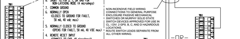
16 Electrical Installation Follow the steps below to wire TB1 and TB2 terminal blocks. Step 1 Step 2 Step 3 Step 4 Step 5 Step 6 Step 7 Use a slotted, narrow-head screwdriver blade to release the spring cage. Place the screwdriver blade into the spring cage. (See Wiring Detail illustration). Push the screwdriver straight down into the spring cage until it touches the bottom. Release the spring cage by pushing the screwdriver away from the wire terminal and holding it in place. (See TB1 Detail illustration). Insert the wire lead into the wire terminal. Release the tension on the screw driver and remove it from the cage. Gently pull on the installed wire to make sure the connection is reliable. Figure 11 - Wiring Detail Field Wiring for TB1 (See Figure 11 - TB1 Detail and Wiring Diagram schematic and Figure 13 EVS Hook-up)) Pin 8 Pin 7 Pin 6 Pin 5 Pin 4 Pin 3 Pin 2 Pin 1 Short to Pin-7 or ground for Non- Latching mode Common Ground Normally Open Alarm Output (closes to ground on fault) Normally Closed to ground Alarm Output (opens from ground on fault) External Reset Input Common Ground DC Power 8-32 VDC Positive 4-20 Current Output (if supplied w/ analog option) Figure 12 TB1 Wiring Diagram


17 Field Wiring for TB2 WARNING! DO NOT CONNECT FIELD WIRING FOR TB1 TO THE TB2 TERMINAL BLOCK. The TB2 Terminal Block is intended for wiring the Internal Battery Pack and the Local Reset Switch. Pin 1 Internal Reset Push Button Ground Pin 2 Internal Reset Push Button Input Pin 3 Internal Battery Pack Negative Pin 4 Internal Battery Pack Positive 7.2 VDC max Figure 13 - TB2 Detail NOTE: Once the Battery Pack has been installed and wired, unnecessary tampering may cause the Faston terminal to come loose, resulting in inaccurate analog/switch operation. WARNING! EXPLOSION HAZARD Do not replace battery unless the area is known to be non-hazardous. Use only batteries made specifically for the Murphy EVS

18 Figure 14 - EVS Hook-up
19 Figure 14 - EVS Hook-up (continued)
20 Settings Setting the Set-point in Inches Per Second (IPS) Peak NOTE: The unit must be set per the application upon installation. Figure 15 EVS Detail for setting IPS and Delay Set-points
21 Method 1 Refer to the monitored machine recommended setting and mounting information and make appropriate adjustments. To adjust the setpoint, open the Murphy EVS cover and follow these steps: 1. Use a slotted, narrow-head screwdriver to adjust the IPS SET potentiometer. 2. To increase the IPS setting, turn the IPS SET potentiometer clock-wise. Tick marks in the EVS indicate 0.1 to 1.5 IPS range in 0.1 IPS increments. 3. To decrease the IPS setting, turn the IPS SET potentiometer counter clockwise. 4. Set the Delay (0-10 seconds, one tick mark per second) according to the tick marks in the EVS. Method 2 When placing the Murphy EVS on a unit where no available instruments or systems identify exactly what the actual vibration of a unit is in IPS Peak, use the following method to customize the setting to the installation, after determining the switch is functioning properly. (Note: This can be performed in Latch or Non-Latching modes.) 1. Make sure that the machine to be monitored is powered on and in normal operation. 2. Press and continue to hold the Local Reset button, located on the right hand side of the Murphy EVS. In this mode the output contact will not change status, only the alarm LED will light. 3. Using a slotted head, screw driver turn the DELAY SET potentiometer to zero. 4. Slowly turn the IPS SET potentiometer counterclockwise until the Alarm LED comes on. 5. Slowly turn the IPS SET potentiometer clockwise until the Alarm LED goes off. 6. Now turn the IPS SET potentiometer 1 or 2 tenths of an IPS higher than the observed trip point. 7. Release the Reset push button. Determining & Adjusting The Delay Set-point The Delay Setpoint value can define the line between sensitivity and nuisance faults. A low delay allows a potentially catastrophic failure to be detected quickly. A higher delay helps prevent normal start-up vibrations from triggering an alarm. An evaluation of these two conditions should be made for each unique installation before setting the Delay Setpoint
22 If start-up vibrations trigger the alarm at the desired delay set-point, the unit can be configured for an unlatched output and wired to a Class B input timer on a Murphy annunciator or controller. If used with a PLC system, the input can be timed out for startup. With the reset input active (pushbutton depressed) the Alarm LED will activate, but the alarm outputs will not change to the alarm state. If the reset pushbutton is released while the unit is in an alarm state, the unit will shut down if that input is active on the annunciator. Optionally, a controller output can be used to hold the EVS in remote reset during startup. To adjust the delay set-point follow these steps: 1. Use a slotted, narrow-head screwdriver to adjust the DELAY SET potentiometer. 2. To increase the delay setting, turn the potentiometer clockwise. Tick marks in the EVS indicate 0 to 10 second range in one (1) second increments. 3. To decrease the delay setting, turn the potentiometer counter clockwise. Useful Vibration Formulas V = πfd V = g/f g = f 2 D g = Vf D = V/f D = g/f 2 V = inches / second g = inches / second 2 D = inches peak-to-peak f = RPM/60 rms = x peak peak-to-peak = 2 x peak π = Setting of Alarms The alarm values may vary considerably, up or down, for different machines. The values chosen will normally be set relative to a baseline value determined from experience for the measurement position or direction for that particular machine. In the following chart, it is recommended that the alarm value should be set higher than the baseline by an amount equal to 25% of the upper limit for Zone B. If the baseline is low, the alarm should be below Zone C. Where there is no established baseline (for example with a new machine) the initial alarm setting should be based either on experience with other similar machines or relative to agreed acceptance values. After a period of time, the steady-state baseline value will be established and the alarm setting should be adjusted accordingly


23 Recommended Alarm Settings The following are guidelines based on industry standards. Actual settings will vary depending on mounting and unit installation. (Note: Refer to the Appendix for recommended settings by specific manufacturers.) Experience with a given installation should be the major factor in deciding the settings. It is recommended that the alarm value should not normally exceed 1.25 times the upper limit of zone B. Vibration Limits Based on Class of Equipment Based on ISO
24 Typical Vibration Alarm Settings of Various Installations THE VALUES LISTED BELOW ARE GUIDELINES ONLY Actual vibration limits must be related to stress levels, which can be measured with strain gage equipment. In general, if vibration levels are below the guidelines mentioned below, the stress levels are well below the fatigue level of the equipment. If vibration problem is perceived, a spectral analysis should be performed on the unit by a qualified specialist. Velocity (IPS peak) Type of Equipment LOW HIGH Compressor, Centrifugal Compressor, Reciprocating Conveyors Electric Motors Engines Fans, Blowers Gear Boxes Generator Sets, Electric Driven Generator Sets, Engine Driven Machine Tools (unloaded) Pumps, Centrifugal Pumps, Gear Pumps, Reciprocating Turbines Reciprocating Compressor Vibration Setting Guidelines THE VALUES LISTED BELOW ARE GUIDELINES ONLY Cyclical failures generally occur in the range of 10 to 100 cycles. High velocity at high frequency will result in failure at a much greater rate than high velocities at a low frequency. Experience should also be a guideline in determining acceptance limits for a particular compressor package. Velocity (IPS peak) Type of Equipment (ips) (mm/sec) Motor Frame Compressor Frame Compressor Cylinder (outer end) Pulsation bottles (outer center) Skid Frame (top) Scrubber (6-6 elevation) Piping (saddles and 12 spans) PSV s (top of valves)
25 Equipment Manufacturer Recommended Settings ARIEL: SKID, FRAMES, CYLINDERS (provided by Ariel) MICROLOG CMVA60 SETUP: Velocity ins/sec, zero to peak If a vibration problem is perceived, a spectral analysis should be preformed on the unit by a qualified vibration specialist. The following chart indicates overall average limits for various models of Ariel equipment. THESE VALUES ARE GUIDELINES ONLY - Actual vibration limits must be related to stress levels, which can be measured with strain gage equipment. In general, if vibration levels are below the guidelines mentioned below, the stress levels are well below the fatigue level of the equipment. Model JG, A, M, N, JGJ, H, E, T, P, Q, R, W K JGC, D, B, V Skid <0.10 IPS <0.15 IPS <0.20 IPS Compressor Frame <0.20 IPS <0.40 IPS <0.20 IPS Compressor Cylinder <0.45 IPS <0.80 IPS <1.0 IPS Chart effective 10/01/00, Check latest limits on Ariel Web Site. Other manufacturer s data will be provided as authorized
26 Specifications Environmental Temperature: -40 and +85 C. Humidity: 0-95% non-condensing Vibration: 30 g s (Mechanical stability) External DC Power Requirement External power: 8-32 VDC. Input Current: 100mA Max Sensor Accuracy / Noise ±5% of full scale at 1.5 ips and 21 deg C. ±5% Variation over temperature from 21 deg C. Integration Stage End-to-End Noise: <0.01 ips RMS ±5%, at Bandwidth of 6 to 500 Hz ±3dB at Bandwidth of 3 to 850 Hz, worst case Trigger Level Feature Adjustable single turn potentiometer between 0.1 and 1.5 inches per second (ips) Peak, in 0.1 increments. Time Delay Feature Adjustable single turn potentiometer from 0 to 10 seconds in 1 second intervals Output Normally-Open (close to ground) on fault Open-collector outputs 50 ma sink capability Input voltage: 40 VDC maximum Output is supplied latched. Provision is incorporated for non-latch operation. Reset accomplished by reset pushbutton or external contact closure. Output circuits based on fault sensitive operation. Alarm activated on power loss
27 LED Outputs Red LED Alarm output: Flashes twice per second for the first 5 minutes when in Alarm mode. After 5 minutes it will flash once every second until reset. Green/Amber LED Power output: Green flash every 6 seconds: Battery status Normal. Amber flash every 6 seconds: Battery in Low-Battery range. 4-20mA output (option) Loop Resistance: 600 ohms max at 24 V and 20mA. Current loop accuracy ±5%. 20 ma corresponds to 1.5 ips Peak 4 ma corresponds to 0 ips Peak Reset Local reset switch w/momentary contact mounted to enclosure and connected to EVS PCB by means of a two wire connector TB2. Non-Incendive circuits for local Push Button and remote contact input External reset: Requires an external dry contact to activate the reset. Activation Period: Reset must be active for 0.5 sec. minimum to reset EVS Approvals (applied for) Class 1 Div 2 Hazardous Area, Groups B,C,D
28 (THIS PAGE INTENTIONALLY LEFT BLANK)
29 MURPHY, the Murphy logo, TTD, Centurion or Millennium and VS2 are registered and/or common law trademarks of Murphy Industries, Inc. This document, including textual matter and illustrations, is copyright protected by Murphy Industries, Inc., with all rights reserved. (c) 2005 Murphy Industries, Inc. Other third party product or trade names referenced herein are the property of their respective owners and are used for identification purposes only.
30
vibration switch
 user manual 440-450 vibration switch INSTALLATION - OPERATION - MAINTENANCE Z0592822_A ISSUED 06/2017 READ AND UNDERSTAND THIS MANUAL PRIOR TO OPERATING OR SERVICING THIS PRODUCT. contents Section 1 -
User's Manual: Series 260A Model 260A Process Current Loop-Powered Alarm
 User's Manual: Series 260A Model 260A Process Current Loop-Powered Alarm Table of Contents Page Introduction 1 Description 1 Specifications 2 Installation 3 Calibration 4 General Maintenance 5 List of
Analog Room Pressure Monitor RPC Series
 Description The Room Pressure Monitor is used to measure differential pressure in the range of 0.125 to 1"wc or 30 to 250 Pa. It combines precision high sensitivity silicon sensing capabilities and the
Thermo Scientific Ramsey TM Series Sensing Speed Conditions on Rotating Shafts and Machinery
 Thermo Scientific Ramsey TM Series 60-200 Sensing Speed Conditions on Rotating Shafts and Machinery The Thermo Scientific Ramsey Series 60-200 monitors under-speed, overspeed and zero-speed conditions
Ramsey Motion Monitoring Systems
 Ramsey Motion Monitoring Systems 60-200 Motion Monitoring Accurate Sensing of Underspeed, Overspeed and Zero Speed Conditions on Rotating Shafts and Machinery The Ramsey Series 60-200 Motion Monitoring
MAINTENANCE & TROUBLESHOOTING GUIDE LEAK ALARM CHANNEL DRY OIL WATER AUX ALARM HIGH LOW CRITICAL WATER TANK LEVEL ALARM MODEL LDE-740 ADVANCE PAPER
 PNEUMERCATOR Liquid Level Control Systems Electronic Systems Excluding LC2000 And TMS Series MAINTENANCE & TROUBLESHOOTING GUIDE 400 300 500 FUEL LEVEL LEAK MONITOR 1 200 600 OIL/GAS NORMAL WATER PNEUMERCATOR
STA16 SELECTRONIC ALARM ANNUNCIATORS DESIGN, INSTALLATION AND OPERATING MANUAL STA16
 ST-97106N Revised 07-04 Section 25 (00-02-0283) STA16 SELECTRONIC ALARM ANNUNCIATORS DESIGN, INSTALLATION AND OPERATING MANUAL STA16 Certain danger to human safety and to equipment may occur if some equipment
ESSEX ENGINEERING CORPORATION
 WATER/WASTEWATER TREATMENT CONTROL SYSTEMS AND SUBSYSTEMS 2000 SERIES CONTROL SYSTEMS: 2000 series are for surface mounting inside a control cabinet Model 2024 Electronic Alternator Duplex (two pump) pump
Ramsey Series Motion Monitoring Systems Accurate Sensing of Speed Conditions on Rotating Shafts and Machinery
 Ramsey Series 60-200 Motion Monitoring Systems Accurate Sensing of Speed Conditions on Rotating Shafts and Machinery Ramsey Series 60-200 Motion Monitoring Systems offer versatile and reliable packages
MODEL 5800A CARBON MONOXIDE (CO) MONITOR AND ALARM SAMPLE-DRAWING TYPE
 MONITOR AND ALARM SAMPLE-DRAWING TYPE") MODEL 5800A CARBON MONOXIDE (CO) MONITOR AND ALARM SAMPLE-DRAWING TYPE 11//07 A153-021500-1 INSTRUCTION MANUAL - MODEL 5800A CO ALARM I INTRODUCTION This MST Model 5800A Carbon Monoxide (CO) Alarm is a
MODEL 5800A CARBON MONOXIDE (CO) MONITOR AND ALARM SAMPLE-DRAWING TYPE 11//07 A153-021500-1 INSTRUCTION MANUAL - MODEL 5800A CO ALARM I INTRODUCTION This MST Model 5800A Carbon Monoxide (CO) Alarm is a
GG-EM ENTRANCE MONITOR. Installation and Operation Manual
 GG-EM ENTRANCE MONITOR Installation and Operation Manual 2 GG-EM Warning Use this product only in the manner described in this manual. If the equipment is used in a manner not specified by Calibration
Series DCT1000DC Dust Collector Timer Controller Specifications Installation and Operating Instructions
 Series DCT1000DC Dust Collector Timer Controller Specifications Installation and Operating Instructions Bulletin E-97DC Thank you for purchasing the Dwyer DCT1000DC Dust Collector Timer Controller. You
MASTER JOCKEY PUMP CONTROLLER. Model JPCE INSTRUCTION MANUAL. C 2018 Master Control Systems, Inc
 MASTER JOCKEY PUMP CONTROLLER Model JPCE INSTRUCTION MANUAL C 2018 Master Control Systems, Inc TABLE OF CONTENTS Important Safety Information. Page 3 General Description and Installation.. Page 4 Model
Dual Point General Purpose Heat Trace Control TRACON MODEL GPT 230 Installation and Operation Manual
 We manage heat MANUAL Dual Point General Purpose Heat Trace Control TRACON MODEL GPT 230 Installation and Operation Manual 1850 N Sheridan Street South Bend, Indiana 46628 (574) 233-1202 or (800) 234-4239
MASTER PRESSRE MAINTANENCE CONTROLLER. Models PMCE INSTRUCTION MANUAL. C 2018 Master Control Systems, Inc
 MASTER PRESSRE MAINTANENCE CONTROLLER Models PMCE INSTRUCTION MANUAL C 2018 Master Control Systems, Inc TABLE OF CONTENTS Important Safety Information. Page 3 General Description and Installation.. Page
Carbon Monoxide Transmitter
 Introduction The CO Transmitter uses an electrochemical sensor to monitor the carbon monoxide level and outputs a field-selectable 4-20 ma or voltage signal. The voltage signal may also be set to 0-5 or
DESIGN MANUAL. The information in this doucment is applicable to sensors built in September, 2009 or later (Firmware 3.0)
") DESIGN MANUAL MODEL GIR910 INFRARED CARBON DIOXIDE (CO 2 ) GAS SENSOR 70091 The information in this doucment is applicable to sensors built in September, 2009 or later (Firmware 3.0) The information and
DESIGN MANUAL MODEL GIR910 INFRARED CARBON DIOXIDE (CO 2 ) GAS SENSOR 70091 The information in this doucment is applicable to sensors built in September, 2009 or later (Firmware 3.0) The information and
Instructions R8471J Gas Controller for use with Model OPECL Open Path Eclipse IR Gas Detector 1.1 1/
 Instructions R8471J Gas Controller for use with Model OPECL Open Path Eclipse IR Gas Detector 1.1 1/08 Table Of Contents Section I Installation and Startup.................. 1 INSTALLATION............................................
Single Point Freeze Protection Heat Trace Control TRACON MODEL FPT 130 Installation and Operation Manual
 We manage heat MANUAL Single Point Freeze Protection Heat Trace Control TRACON MODEL FPT 130 Installation and Operation Manual 1850 N Sheridan Street South Bend, Indiana 46628 (574) 233-1202 or (800) 234-4239
MODEL FPT-130 SINGLE POINT FREEZE PROTECTION HEAT TRACE CONTROL
 TRACON MODEL FPT-130 SINGLE POINT FREEZE PROTECTION HEAT TRACE CONTROL TABLE OF CONTENTS FPT 130 Overview... 2 Installation... 3 Power Source and Load Connections... 4 Temperature Sensor... 5 External
Refrigeration Controller Operator s Manual (HRC) PO Box 6183 Kennewick, WA
 PO Box 6183 Kennewick, WA") Refrigeration Controller Operator s Manual (HRC) PO Box 6183 Kennewick, WA 99336 www.jmcvr.com 1-509-586-9893 Table of Contents TABLE OF FIGURES...1 OVERVIEW OF THE HRC CAPABILITIES...2 INSTALLATION AND
Refrigeration Controller Operator s Manual (HRC) PO Box 6183 Kennewick, WA 99336 www.jmcvr.com 1-509-586-9893 Table of Contents TABLE OF FIGURES...1 OVERVIEW OF THE HRC CAPABILITIES...2 INSTALLATION AND
Selectronic Tattletale Remote Alarm Annunciators
 Selectronic Tattletale Remote Alarm Annunciators ST-95046B Revised 08-06 Catalog Section 25 ST Series Provide Audible and Visual Alarm Simple and Inexpensive Wide Range of Applications Gen-Set Models Meet
MODEL A-316 CARBON MONOXIDE (CO) MONITOR AND ALARM FOR COMPRESSED AIR TESTING
 MONITOR AND ALARM FOR COMPRESSED AIR TESTING") MODEL A-316 CARBON MONOXIDE (CO) MONITOR AND ALARM FOR COMPRESSED AIR TESTING FOR OPERATION FROM 115 AC POWER Andersen Medical Gas 12 Place Lafitte Madisonville, LA 70447 http://www.themedicalgas.com 1-866-288-3783
MODEL A-316 CARBON MONOXIDE (CO) MONITOR AND ALARM FOR COMPRESSED AIR TESTING FOR OPERATION FROM 115 AC POWER Andersen Medical Gas 12 Place Lafitte Madisonville, LA 70447 http://www.themedicalgas.com 1-866-288-3783
Frequently asked questions: Intelligent Transmitter Series
 Frequently asked questions: Intelligent Transmitter Series The Wilcoxon family of Intelligent Transmitters, relay alarms, and communication modules can be used to implement low-cost online vibration monitoring
Vibration Of Cooling Tower Fans. Barry T. Cease Cease Industrial Consulting Vibration Institute 2015
 Vibration Of Cooling Tower Fans Barry T. Cease Cease Industrial Consulting Vibration Institute 2015 ceasevibration@icloud.com (843) 200-9705 1 WHAT IS A COOLING TOWER AND WHAT DOES IT DO? All cooling towers
LHE OIL LINE HEATER ELECTRIC TYPE
 INSTRUCTIONS LHE OIL LINE HEATER ELECTRIC TYPE WARNING These instructions are intended for use only by experienced, qualified combustion start-up personnel. Adjustment of this equipment and its components
SuperKlean Washdown Products
 DURAREEL DR8 & DR8S INSTALLATION AND MAINTENANCE INSTRUCTIONS **DO NOT THROW AWAY AFTER INSTALLATION** **SAVE AND DISPLAY PROMINENTLY WHERE THIS EQUIPMENT IS USED** GENERAL WARNINGS High pressure and hot
Pipe Freeze Protection Control SCFP-CO-F130 Installation and Operation Manual
 MANUAL Pipe Freeze Protection Control SCFP-CO-F130 Installation and Operation Manual Model FPT 130 Single Point Freeze Protection Heat Trace Control Table of Contents SCFP-CO-F130 Overview... 3 Installation...
Secure the other corner. bracket using the remaining screw,
 Mount the E-FENCE1 directly to the fabric of the chain link or wire mesh, on the interior side of the protected area as shown in the illustrated examples, at a height of 4 5 feet and 1 foot from a post.
ANSUL ANSUL AUTOMAN II-C RELEASING DEVICE
 ANSUL INSTALLATION OPERATION AND MAINTENANCE MANUAL ANSUL AUTOMAN II-C RELEASING DEVICE 001799 This manual is intended for use with the ANSUL AUTOMAN II-C Releasing Device. Those who install, inspect,
MANUAL RESET ALARM RELEASE
 Fire Door Release MODEL AR-D2 MANUAL RESET ALARM RELEASE INSTRUCTION MANUAL AR-D2 GENERAL INFORMATION 1. Review all installation instructions, procedures, cautions and warnings contained within this manual
Active Infrared Multi Beam Sensors
 Active Infrared Multi Beam Sensors D Series TECHNICAL MANUAL INDEX GENERAL SAFETY RECOMMENDATIONS 3 CONFORMITY 4 WARRANTY 4 INTRODUCTION 5 FEATURES 5 OPERATIONAL RANGE 6 SETUP TRANSMITTER (TX) 6 SETUP
rev3 INSTALLATION & OPERATION MANUAL OIL CIRCULATING HEATING SYSTEM MODEL OSM
 216279-000 rev3 INSTALLATION & OPERATION MANUAL OIL CIRCULATING HEATING SYSTEM MODEL OSM IDENTIFYING YOUR SYSTEM IOM216279-000 The HOTSTART heating system is designed to heat fluids for use in marine
SEC 2000 Millenium Infrared Gas Detector
 SEC 2000 Millenium Infrared Gas Detector Instruction and Operation Manual Sensor Electronics Corporation 5500 Lincoln Drive Minneapolis, Minnesota 55436 USA (952) 938-9486 Fax (952) 938-9617 Email: sales@sensorelectronic.com
SCR/SCRF Series Battery Charger
 JD0036-00 Installing and Calibrating the Combined Alarm-Status Monitor (CASM) Scope Reference Materials Required 1. Installing a new CASM option (EJ0837-##) 1 2. Replacing a CASM circuit board (EN0014-##)
Active Infrared Multi Beam Sensors. R Series
 Active Infrared Multi Beam Sensors R Series TECHNICAL MANUAL INDEX GENERAL SAFETY RECOMMENDATIONS 3 CONFORMITY 4 WARRANTY 4 INTRODUCTION 5 FEATURES 5 OPERATIONAL RANGE 6 SETUP TRANSMITTER (TX) 6 SETUP
DESCRIPTIVE AND INSTALLATION INSTRUCTION MANUAL FOR MODEL G1000 AND H1000 SERIES ANNUNCIATORS
 DESCRIPTIVE AND INSTALLATION INSTRUCTION MANUAL FOR MODEL G1000 AND H1000 SERIES ANNUNCIATORS SEEKIRK, INC. 2420 Scioto Harper Dr. Columbus, OH 43204 Tel: (614) 278-9200 FAX: (614) 278-9257 email: seekirk@seekirk.com
Dual Point General Purpose Heat Trace Control TRACON MODEL GPT 230 Installation and Operation Manual
 We manage heat MANUAL Dual Point General Purpose Heat Trace Control TRACON MODEL GPT 230 Installation and Operation Manual 1850 N Sheridan Street South Bend, Indiana 46628 (574) 233-1202 or (800) 234-4239
Design Manual Installation Operation Maintenance
 Design Manual Installation Operation Maintenance Model GT824 NOVA-Sensor ELITE Oxygen Monitoring Detector 70115 23282 Mill Creek Drive, Suite 215 Laguna Hills, CA 92653 USA +1.949.583.1857 Phone +1.949.340.3343
MANUAL RESET ALARM RELEASE
 Fire Door Release MODEL AR-D MANUAL RESET ALARM RELEASE INSTRUCTION MANUAL AR-D GENERAL INFORMATION 1. Review all installation instructions, procedures, cautions and warnings contained within this manual
Belt Conveyor Safety Monitoring Devices
 ISO-00:000 certified Belt Conveyor Safety Monitoring Devices More than just another level measurement company. Aplus Finetek Sensor, Inc. SRT CONVEYOR BELT MISALIGNMENT SWITCH PRODUCT INTRODUCTION The
DL424/425 DirectLine Sensor Module for Dissolved Oxygen Probes Series DL5000 Specifications
 DL424/425 DirectLine Sensor Module for Dissolved Oxygen Probes Series DL5000 Specifications 70-82-03-48 January 2003 Overview The DirectLine DL424/425 Sensor Modules are part of a family of products developed
Pioneer-R16 Gas Monitor Operator s Manual
 Pioneer-R16 Gas Monitor Operator s Manual Edition 7/2/97 RKI INSTRUMENTS, INC RKI Instruments, Inc. 33248 Central Ave, Union City, CA 94587 (510) 441-5656 Chapter 1: Description About the Pioneer-R16 Gas
Tachometer/Hourmeter/Trip. Installation and Operation Manual
 3211 Fruitland Ave Los Angeles, CA 90058 MTH-103E Tachometer/Hourmeter/Trip Installation and Operation Manual Rev. G P/N 145F-13048 PCO - 00010525 Copyright 2014-2017, Barksdale Inc. All Rights Reserved
EXTINGUISHING AGENT RELEASE MODULE
 EXTINGUISHING AGENT RELEASE MODULE Operation, Installation & Programming Manual Revision 3.00 Distributors For: 18-20 Brookhollow Ave telephone 02 8850 2888 www.firesense.com.au Baulkham Hills NSW 2153
Sierra Series 900 Single & Dual Channel System. Instruction Manual
 Series 240/24 Instruction Manual Table of Contents Sierra Series 900 Single & Dual Channel System Instruction Manual Part Number IM-90-07/05 Revision D. 5 Harris Court, Building L Monterey, CA 93940 (83)
DESCRIPTIVE AND INSTALLATION INSTRUCTION MANUAL FOR MODEL AH1000, BH1000, AND EH1000 SERIES ANNUNCIATORS
 DESCRIPTIVE AND INSTALLATION INSTRUCTION MANUAL FOR MODEL AH1000, BH1000, AND EH1000 SERIES ANNUNCIATORS SEEKIRK, INC. 2420 Scioto Harper Dr. Columbus, OH 43204 Tel: (614) 278-9200 FAX: (614) 278-9257
F PC and AO OUTPUT BOARDS INSTRUCTION MANUAL. Blue-White. Industries, Ltd.
 F-2000 PC and AO OUTPUT BOARDS INSTRUCTION MANUAL Blue-White R Industries, Ltd. 500 Business Drive Huntington Beach, CA 92649 USA Phone: 714-89-8529 FAX: 714-894-9492 E mail: sales@blue-white.com or techsupport@blue-white.com
1040 Gas Monitor INSTALLATION AND OPERATING INSTRUCTIONS AMC-1040 WITH INTEGRAL ELECTROCHEMICAL SENSOR
 1040 Gas Monitor INSTALLATION AND OPERATING INSTRUCTIONS AMC-1040 WITH INTEGRAL ELECTROCHEMICAL SENSOR IMPORTANT: Please read these installation and operating instructions completely and carefully before
TraceTek Sensing Module Installation, Operation and Maintenance Instructions DESCRIPTION SPECIFICATIONS APPROVALS TYPE NM
 TTC-1 TraceTek Sensing Module Installation, Operation and Maintenance Instructions DESCRIPTION The nvent RAYCHEM TraceTek TTC-1 sensing module is used with TraceTek sensing cables to detect liquid leaks.
RELEASE DEVICES RELEASE DEVICE-WPS MODELS A/B INSTALLATION MANUAL U.L. LISTED CANADIAN LISTED CSFM: :100 GENERAL DESCRIPTION:
 RELEASE DEVICES MADE IN THE U.S.A. RELEASE DEVICE-WPS MODELS A/B INSTALLATION MANUAL U.L. LISTED CANADIAN LISTED CSFM: 7300-1418:100 GENERAL DESCRIPTION: S/N: The "WPS" World Power Series, Time Delay Release
Instructions Oxygen Controller R8471C 2.1 8/
 Instructions 95-8405 Oxygen Controller R8471C 8/07 95-8405 Table Of Contents Section I - General Information APPLICATION...1 FEATURES...1 DESCRIPTION...1 SPECIFICATIONS...2 Controller...2 C7052C O2 Detector...2
S304 and S305 Dust Emission Monitors. User Manual. Distributor
 S304 and S305 Dust Emission Monitors User Manual Distributor Version 6.4 30/5/2012 Table of Contents 1. INTRODUCTION... 3 1.1 Safety... 3 1.2 Product overview... 4 1.3 Principle of operation... 4 2. INSTALLATION...
M Series Fan Filter Units
 M Series Fan Filter Units Product Specifications... 2 Safety Instructions... 3 Receiving and Unpacking... 3 Pre-Installation Instructions... 3-4 Installation Instructions... 4 Electrical Installation Instructions...
DESIGN MANUAL MODEL GIR900 INFRARED COMBUSTIBLE GAS SENSOR
 DESIGN MANUAL MODEL GIR900 INFRARED COMBUSTIBLE GAS SENSOR 70086 The information in this doucment is applicable to sensors built in September, 2008 or later (Firmware 3.0) The information and technical
RK CO 2 Transmitter Operator s Manual
 65-2397RK CO 2 Transmitter Operator s Manual Part Number: 71-0185RK Revision: B Released: 7/18/14 RKI Instruments, Inc. www.rkiinstruments.com WARNING Read and understand this instruction manual before
SOLID STATE SECURITIES, INC. THE "SS90" SERIES RELEASE DEVICES MADE IN THE U.S.A. SS90-WPS MODEL A/B INSTALLATION MANUAL
 S S S S S S LISTED L * PATENT PENDING S S 90 OLID TATE ECURITIES, INC SOLID STATE FAIL-SAFE UNIT U 99Y9 RESET RELEASING DEVICE SOLID STATE SECURITIES, INC. THE "SS90" SERIES RELEASE DEVICES MADE IN THE
Firefly II Multi Voltage RELEASE DEVICES. Firefly II & IIB-MV INSTALLATION MANUAL
 Firefly II Multi Voltage RELEASE DEVICES Firefly II & IIB-MV INSTALLATION MANUAL GENERAL DESCRIPTION: S/N The The Cookson Company Firefly II-MV time delay release devices are designed for use on rolling
Fiber Optic Cable Fence Disturbance Sensor
 Architectural & Engineering Specification for Fiber Optic Cable Fence Disturbance Sensor Purpose of document This document is intended to provide performance specifications and operational requirements
RK-05 Combustible Gas Transmitter Operator s Manual
 65-2405RK-05 Combustible Gas Transmitter Operator s Manual Part Number: 71-0180RK Revision: 0 Released: 2/16/11 RKI Instruments, Inc. www.rkiinstruments.com WARNING Read and understand this instruction
ANNUNCIATOR INSTRUMENTS Model PD141AFO Instruction Manual
 ANNUNCIATOR INSTRUMENTS Model PD141AFO Instruction Manual From urgent alarms to routine messages, the PD141AFO VIGILANTE handles all types of operational messages with simplicity and economy. The VIGILANTE
PTE0705 Electric Fence Monitor
 PTE0705 Electric Fence Monitor The JVA logo is a registered trademark of JVA Technologies. JVA Technologies. TABLE OF CONTENTS DESCRIPTION... 2 QUICK START GUIDE... 3 FEATURES... 4 EXPLANATION OF TERMS...
Isco 3700ZR Sampler. Manual Set
 Isco 3700ZR Sampler Manual Set Assembly #60-2744-045 Copyright 2001. All rights reserved, Teledyne Isco Revision D, December 14, 2012 This set of manuals supports the Isco 3700ZR Refrigerated Sampler.
Public Safety DAS Annunciator Panel
 Public Safety DAS Annunciator Panel 120 VAC Models: 1221-A, 1221-B, 1221-C Revision D 91117 48 VDC Models: 1221-A-48, 1221-B-48, 1221-C-48 24 VDC Models: 1221A-24, 1221-B-24, 1221-C-24 CAUTION: (Read This
52 CEILING FAN READ AND SAVE THESE INSTRUCTIONS FAN RATING AC 120V.
 Irene 52 CEILING FAN READ AND SAVE THESE INSTRUCTIONS FAN RATING AC 120V. 60Hz TABLE OF CONTENTS Tools and Materials Required... 1 Package Contents... 1 Safety Rules... 2 Mounting Options... 3 Hanging
INSTALLATION & OPERATION MANUAL
 216300-000 rev2 INSTALLATION & OPERATION MANUAL OIL CIRCULATING HEATING SYSTEM FOR HAZARDOUS LOCATIONS MODEL OSE OSX (this page intentionally left blank) IDENTIFYING YOUR SYSTEM IOM216300-000 The HOTSTART
DAGNY LK. Ceiling Mounted Rotational Fan READ AND SAVE THESE INSTRUCTIONS. FAN RATING AC 110V~60Hz
 DAGNY LK Ceiling Mounted Rotational Fan READ AND SAVE THESE INSTRUCTIONS FAN RATING AC 110V~60Hz Please do not use any electric or battery powered tools in the assembly and installation of this or any
RK Carbon Monoxide Transmitter Operator s Manual
 65-2434RK Carbon Monoxide Transmitter Operator s Manual Part Number: 71-0061RK Edition: First, Revision C Released: December 2001 65-2434RK CO Transmitter 1 Product Warranty RKI Instruments, Inc., warranties
XT Series Thermostats
 ISO 9001 Explosion-Proof & Moisture Resistant XT Series Thermostats Installation, Operation, & Maintenance Instructions XTWA Thermostat XTWL Thermostat XTB Thermostat Part No.MI133.Rev.2.00 Date of Issue:
DSD-3 DIFFERENTIAL SPEED DETECTOR
 DSD-3 DIFFERENTIAL SPEED DETECTOR Instruction Manual PL-207 June 1993 PROCESS MEASUREMENTS 33452070 ABOUT THIS MANUAL This manual covers the installation and operation of the DSD-3. It is essential that
RK Hydrogen Sulfide Transmitter Operator s Manual
 65-2331RK Hydrogen Sulfide Transmitter Operator s Manual Part Number: 71-0176RK Revision: B Released: 11/26/14 RKI Instruments, Inc. www.rkiinstruments.com WARNING Read and understand this instruction
SAFETY INFORMATION AND WARNINGS
 This manual refers to the Model SST-3 control panel manufactured since October 31, 2013, which uses a universal (100 277 VAC; 50/60 Hz) power supply. Older units use a voltage-specific power supply and
INTRODUCTION / TABLE OF CONTENTS
 1 2 INTRODUCTI / TABLE OF CTENTS Step One The LVCN 51 Series Continuous Relay Controller is a general purpose level controller which provides single tank level indication with dual relays and a repeater
BESF Box Ventilator USA CAN. Product Information. Mechanical Installation. ... Chapter 3. Electrical Installation. ... Chapter 4
 Installation & Operating Manual BESF Box Ventilator USA CAN Product Information... Chapter 1 + 2 Mechanical Installation... Chapter 3 Electrical Installation... Chapter 4 Start Up and Configuration...
KD-CLN-LP200 Ultrasonic Vinyl Record Cleaner User s Manual English v1.2 Printed in Korea
 TM TM www.klaudio.com KD-CLN-LP200 Ultrasonic Vinyl Record Cleaner User s Manual English v1.2 Printed in Korea s are updated regularly. Please be sure to check our support page for a newer version of this
Duct and Rough Service Carbon Monoxide Sensor
 Product Identification and Overview Duct and Rough Service Carbon Monoxide Sensor BAPI s Carbon Monoxide Sensor offers enhanced electrochemical sensing with outstanding accuracy at low concentrations.
THE "SS90" SERIES RELEASE DEVICES MADE IN THE U.S.A. MODELS A/B INSTALLATION MANUAL
 S S S S S S OLID TATE ECURITIES, INC S S 90 SOLID STATE FAIL-SAFE UNIT * PATENT PENDING LISTED 99Y9 RESET U L RELEASING DEVICE SOLID STATE SECURITIES, INC. THE "SS90" SERIES RELEASE DEVICES MADE IN THE
SERVICE MANUAL MULTI DECK 60 HOT MERCHANDISER MULTI DECK 100 HOT MERCHANDISER MULTI DECK 120 HOT MERCHANDISER CLASSIC DECK HOT MERCHANDISER
 SERVICE MANUAL MULTI DECK 60 HOT MERCHANDISER MULTI DECK 100 HOT MERCHANDISER MULTI DECK 120 HOT MERCHANDISER CLASSIC DECK HOT MERCHANDISER Classic Deck Hot Multi Deck 60 Multi Deck 100 Multi Deck 120
INSTALLATIONN GUIDE & OPERATION MANUAL
 INSTALLATION INSTRUCTIONS ECO # 1569 REVISION #0006 FCS SERIES MODEL 5025, 5045,7525 & 7545 INSTALLATION INSTRUCTIONS BY: DATE: 01/23/2013 INSTALLATIONN GUIDE & OPERATION MANUAL MOTOR OPERATOR (V3.02 Controls)
ACSI AO ELECTRIC LATCH RETRACTION CONTROLLER INSTALLATION INSTRUCTIONS I.D. 1089, REV. F
 II 1400-2 ACSI 1406-04-AO ELECTRIC LATCH RETRACTION CONTROLLER INSTALLATION INSTRUCTIONS I.D. 1089, REV. F INSTALLATION Transformer Model BE31763001 by Basler Electric, Transformer Model 2010028 by Galaxy
MagnaValve Shot Flow Controller
 Instruction Manual MagnaValve Shot Flow Controller Electronics Inc. 56790 Magnetic Drive Mishawaka, Indiana 46545 1-800-832-5653 (Toll Free) Phone: 1-574-256-5001 Fax: 1-574-256-5222 E-mail: sales@electronics-inc.com
ANSUL AUTOMAN II-C EXPLOSION PROOF RELEASING DEVICE Installation, Operation, and Maintenance Manual
 ANSUL AUTOMAN II-C EXPLOSION PROOF RELEASING DEVICE Installation, Operation, and Maintenance Manual 001799 This manual is intended for use with the ANSUL AUTOMAN Il-C Explosion-Proof Releasing Device.
Instruction Manual Model A
 706 Bostwick Avenue, Bridgeport, CT 06605 TEL: 203-368-6751 FAX: 203-368-3747 1-800-566-6822 www.devarinc.com Instruction Manual Model 18-232A LOOP POWERED ALARM MANUAL NO. 990029 MODEL 18-232A LOOP POWERED
Revision: None DCN No. First Issue Date: November 30, 1998 Product: Standard DCT, 120-volts
 Figure 1Document: SPEC-112 Revision: None DCN No. First Issue Date: November 30, 1998 Product: Standard DCT, 120-volts construction requirements of UL approved Class H (180 C) insulation system. Transformers
RK Carbon Monoxide Transmitter Operator s Manual
 65-2335RK Carbon Monoxide Transmitter Operator s Manual Part Number: 71-0177RK Revision: 0 Released: 4/12/11 RKI Instruments, Inc. www.rkiinstruments.com WARNING Read and understand this instruction manual
AMC-RAM-4. Refrigerant Alarm Module USER MANUAL. Please read the installation and operating instructions completely and carefully before starting.
 AMC-RAM-4 Refrigerant Alarm Module USER MANUAL IMPORTANT: Please read the installation and operating instructions completely and carefully before starting. Filename: 3310405B, DOC, AMC_RAM4_Manual.doc
INSTRUMENTATION AND CONTROL DEVICES FOR HVAC
 PART 1 GENERAL 1.01 RELATED REQUIREMENTS SECTION 23 0913 INSTRUMENTATION AND CONTROL DEVICES FOR HVAC A. Section 26 2717 - Equipment Wiring: Electrical characteristics and wiring connections. 1.02 ADMINISTRATIVE
MYRIAD TRIPLEX PUMP CONTROLLER INSTRUCTION MANUAL
 MYRIAD TRIPLEX PUMP CONTROLLER INSTRUCTION MANUAL MYRIAD TPC VISIT OUR WEBSITE SIGMACONTROLS.COM MYRIADI&O062705 2 TABLE OF CONTENTS INTRODUCTION 3 Ordering Information Specifications Features WIRING 7,8
21-light Remote Annunciator. Owner s Manual
 21-light Remote Annunciator Owner s Manual Annunciator Description... Inside Font Cover Detailed Specifications... 1 Environmental Specifications... 1 Power Supply Requirements... 1 Communication With
M2 Rig Monitor Operator s Manual
 M2 Rig Monitor Operator s Manual Part Number: 71-0234RK Revision: D Released: 9/30/14 RKI Instruments, Inc. www.rkiinstruments.com WARNING Read and understand this instruction manual before operating instrument.
SP-1000X. Panic Device Power Controller Installation Guide. Rev
 TM SP-1000X Panic Device Power Controller Installation Guide Rev. 120213 Overview: SP-1000X will operate up to two (2) 24VDC panic hardware devices simultaneously. It is designed to handle the high current
TCA-9102 Series Surface Mount Temperature Controllers with High and Low Alarm
 TCA-9102 Series Surface Mount Temperature Controllers with High and Low Alarm General Description & Applications The TCA-9102 Series Temperature Controller with Alarm offers a versatile solution for a
MODEL GPT-130 SINGLE POINT HEAT TRACE CONTROL THERMOSTAT
 TRACON MODEL GPT-130 SINGLE POINT HEAT TRACE CONTROL THERMOSTAT TABLE OF CONTENTS GPT 130 Overview... 2 Installation... 3 Power Source and Load Connection... 4 Temperature Sensor Installation... 5 Panel
BESB Box Ventilator USA CAN. Product Information. Mechanical Installation. ... Chapter 3. Electrical Installation. ... Chapter 4
 Installation & Operating Manual BESB Box Ventilator USA CAN Product Information... Chapter 1 + 2 Mechanical Installation... Chapter 3 Electrical Installation... Chapter 4 Start Up and Configuration...
INTRODUCTION / TABLE OF CONTENTS
 1 2 INTRODUCTION / TABLE OF CONTENTS Step One Offered in liquid and gas sensor types, the general purpose flow switch provides reliable low or no flow detection of relatively clean, non coating media with
RKA-LEL Sample Draw Combustible Gas Detector
 35-3000RKA-LEL Sample Draw Combustible Gas Detector Specifications Table 1 lists specifications for the sample draw combustible gas detector. Table 1: Specifications Target Gas Input Power Combustible
RK-05 Carbon Monoxide Transmitter Operator s Manual
 65-2432RK-05 Carbon Monoxide Transmitter Operator s Manual Part Number: 71-0113RK Revision: B Released: 11/26/14 www.rkiinstruments.com WARNING Read and understand this instruction manual before operating
Independent Zone Control (I.Z.C.)
") Operation and Installation Guide Independent Zone Control (I.Z.C.) DELAYED INSTANT ARMED 1 2 3 4 7 5 6 8 9 * * fi Radionics R D279A Operation & Installation Guide 46456B Page 2 Copyright 2000 Radionics
Operation and Installation Guide Independent Zone Control (I.Z.C.) DELAYED INSTANT ARMED 1 2 3 4 7 5 6 8 9 * * fi Radionics R D279A Operation & Installation Guide 46456B Page 2 Copyright 2000 Radionics
Alnor AirGard 410HE Air Flow Monitor for Hazardous Environment Fume Hoods
 Air Flow Monitors Alnor AirGard 410HE Air Flow Monitor for Hazardous Environment Fume Hoods Owner s Manual LIMITATION OF WARRANTY AND LIABILITY (effective June 2011) Seller warrants the goods sold hereunder,
FIREFLY II PLUS RELEASE DEVICES INSTALLATION MANUAL
 FIREFLY II PLUS RELEASE DEVICES INSTALLATION MANUAL MADE IN THE U.S.A. U.L. LISTED CANADIAN LISTED CSFM: 7300-1418:100 GENERAL DESCRIPTION SERIAL NUMBER The Cookson Company FIREFLY II PLUS Time Delay Release