Secure the other corner. bracket using the remaining screw,
|
|
|
- Lizbeth Thornton
- 5 years ago
- Views:
Transcription
1


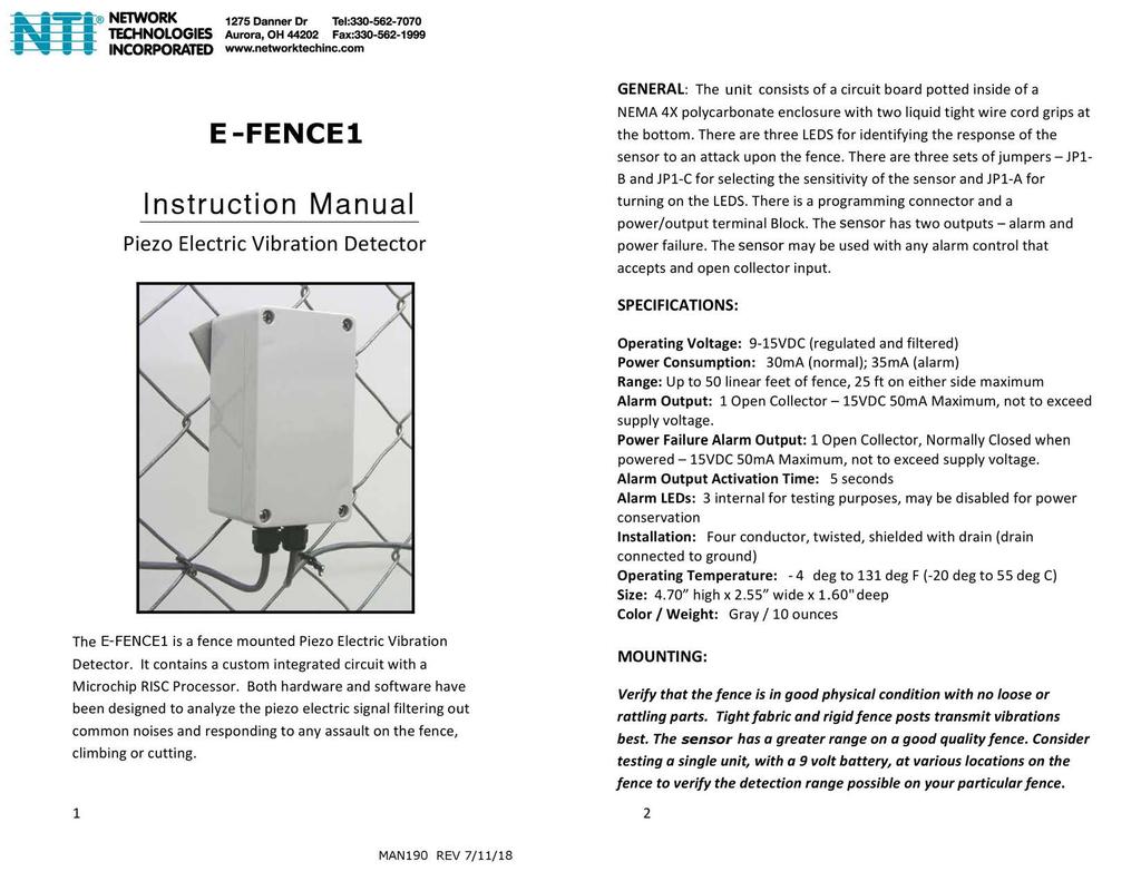
2 Mount the E-FENCE1 directly to the fabric of the chain link or wire mesh, on the interior side of the protected area as shown in the illustrated examples, at a height of 4 5 feet and 1 foot from a post. The mounting hardware consists of an aluminum plate with two screws, used to clamp the sensor enclosure to the fence fabric. Loosely secure the mounting bracket to the E-FENCE1, with one screw only in the upper corner of the E-FENCE1 Secure the other corner of the E-FENCE1 to the bracket using the remaining screw, centering the E-FENCE1 in the links and tighten so that the E-FENCE1 makes good contact with the chain links. DO NOT OVER TIGHTEN. Feed the bracket thru the fence fabric diagonally, down and to the right, capturing 2 3 wires, depending on link size. There is no need to tighten so much that the bracket is pulled fully to the case and bent or that the case of the E- FENCE1 case begins to twist and deform. This will prevent a water tight seal with the lid. 3 4
3 KEY COMPONENTS: LEDs: Each E-FENCE1 has three LEDs Green, Amber and Red. These LEDs indicate the response of the sensor to impacts or cuts to the fence. Red LED: Alarm Output Amber LED: Qualified Event Green LED: Activity on the Fence Green LED The Green LED will indicate that the E-FENCE1 has received a signal from the impact and will process that signal to qualify it as a valid event. If the Green LED does not flash during a valid attack upon the fence, the sensitivity of the E-FENCE1 must be increased, or the distance between the sensors reduced. Also, if there is a steady wind or the fence is vibrating as if there is a steady wind then the Green LED will not illuminate unless the impact exceeds the vibration due to wind. Note: Disconnect power after each test to reset LED function, see below TESTING. Programming Port: Factory Only ** Do Not Remove Cover ** A B C JP1 Yellow LED The Yellow LED will indicate that the E-FENCE1 has qualified a signal as a valid event. If the Green LED flashes, but the Yellow does not flash during a valid attack upon the fence, the sensitivity of the E-FENCE1 must be increased, or the distance between the sensors reduced. JP1A: On = LED Enable, Off = LED Disable JP1B AND C: Sensitivity Settings Red LED The Red LED will indicate that the E-FENCE1 has counted enough events to qualify as an alarm and has produced an alarm output. SELECTING THE SENSOR SENSITIVITY FOR YOUR FENCE: Terminal: 4 Positions: 12V Common, Alarm Output, +12V Power and Power Failure Output Each E-FENCE1 Sensor has four sensitivity settings High Sensitivity with Wind Mode, Low Sensitivity with Wind Mode, High Sensitivity and Low Sensitivity. A built in microprocessor counts and times the pulses generated by an impact to the fence. The different sensitivities allow you to select an alarm output specific to your fence that matches up with the quantity of pulses and duration of pulses of a valid attack. In order to select the desired sensitivity for your fence, there are two removable Jumpers, JP1 B and JP1 C. The Jumpers allow you to select from the four pre programmed alarm sensitivities. 5 6
4 JP1 B On, JP1 C On = High Sensitivity with Wind Mode JP1 B On, JP1 C Off = Low Sensitivity with Wind Mode JP1 B Off, JP1 C On = High Sensitivity JP1 B Off, JP1 C Off = Low Sensitivity Remove power to the E-FENCE1 Sensor prior to changing Jumpers. Once Jumpers are put back in the desired position reconnect power. Choosing the sensor sensitivity depends upon the quality of the fence loose or tight, heavy or light link gauge, old or new, the height of the fence short 5 ft. to regular 6 8 ft. to tall >8 ft. and the surrounding environment remote or public, protected or windy. Selecting the sensitivity is a balance between generating an alarm output upon a valid attack to the fence and filtering out nuisance events. On a new tight fence of regular height, the sensor will work well with a low sensitivity setting. On a loose or older fence, the E-FENCE1 will work best with a high sensitivity setting. High sensitivity settings can be selected for remote areas with no public access but low sensitivity settings are better for fences adjacent to public areas. In addition to two regular sensitivity settings, High and Low, the E-FENCE1 has two sensitivity settings with Wind Mode. In Wind Mode the E- FENCE1 measures vibration on the fence due to wind or a constant vibration source and measures an impact due to climbing or cutting against this constant vibration. In Wind Mode the sensitivity of the E-FENCE1 sensor will decrease with an increase in wind. For this reason the two sensitivity settings with Wind Mode are less sensitive than the two settings without Wind Mode. If the fence that is being protected is in a clear area with wind then select one of the sensitivity settings with Wind Mode. If the fence is in an area with little wind or protected by other buildings then choose one of the regular settings. 7 TESTING: With the VIB200 mounted to the fence and the cover removed, select the sensitivity with Jumpers JP1 B and JP1 C per the guidelines above. Hook up a 9V battery to the sensor. Test the ability of the sensor to detect impacts and climbs at the desired range (30 to 50 feet). Move the sensor to various parts of the fence and test. The LEDs will alert you to the response of the sensor. One of the unique aspects of the E-FENCE1 is that each individual sensor can be tuned to a particular fence section. Often the quality of the fence can vary from one section to the next. Decrease or increase the sensitivity of the sensor by changing Jumpers JP1 B and JP1 C to generate an alarm upon the degree of impact / attack to the fence you want to identify. A good rule of thumb is to select a sensitivity that generates an alarm at the 3 rd or 4 th step in a climb. At this sensitivity the sensor should not generate an alarm at a single impact to the fence. When testing with a battery, you must disconnect the battery from the sensor after each test in order for the sensor counter and timer to reset. The counters will also reset once the sensor produces an alarm output and the RED LED flashes. Don t forget to disconnect the battery when changing the sensitivity setting also. Once you have selected an appropriate sensitivity and sensor spacing, mount all of the sensors to the fence and wire to power and alarm control. At any time, the sensitivity of one or more of the E-FENCE1 sensors may be changed to tune them to a particular section of fence or desired response. 8

5 WIRING: The Alarm is an open collector output normally open. The Power Trouble is an open collector output normally closed. The Alarm Output will provide an electrical short to ground when activated. The Power Trouble Output will open when activated. Refer to your Alarm Control Panel s Instruction Manual for instructions on how to wire open collector outputs to the zone inputs of the panel. Diagram 1: Output Electrical Configuration WIRING (Continued): The E-FENCE1 may be wired with one loop for alarm and one loop for power trouble to be monitored by two zones on control panel or the alarm and power trouble may be combined on one loop. Always connect the End of Line Resistors in the last E-FENCE1 along the zone run. Note: On long runs you may need to adjust the value of the EOL Resistor to compensate for any voltage drop along the loop. Call NTI to work out best resistor value. Diagram 2: Wiring Diagram for combined alarm and power trouble loop Wrap wire around terminal for best connection. Jumpers JP1 A is used to turn On/Off LEDs. JP1 B and JP1 C are used to select sensitivity. Keep white five pin cover on serial port to protect pins. 9 10

6
TECHNICAL DATA SHEET CONVENTIONAL FIRE ALARM SYSTEMS Conventional Fire Alarm Control Panel
 CVENTIAL ALARM S Features: Description: The LF-CP Series Fire Alarm Control Panel is manufactured based on advanced technology while maintaining high quality during assembly. It is of solid state circuitry
Table of Contents 1. OVERVIEW SYSTEM LAYOUT SPECIFICATIONS FUNCTION... 11
 Table of Contents 1. OVERVIEW... 3 2. SYSTEM LAYOUT... 4 3. SPECIFICATIONS... 8 3.1 SYSTEM COMPONENTS...9 3.2 PLC INPUTS AND OUTPUTS...9 3.3 FUNCTION KEYS...10 3.4 DEFAULT SET POINTS AND TIMERS...10 4.
Section PERIMETER SECURITY SYSTEMS
 Section 28 16 43 PERIMETER SECURITY SYSTEMS PART 1 GENERAL 1.1 SUMMARY A. Provide and install a perimeter security system as herein specified for the purpose of detecting entry into a designated security
G.M. Advanced Fencing & Security Technologies Ltd
 GM Advanced Fencing & Security Technologies Ltd V-ALERT Perimeter Security Intrusion Detection System INSTALLATION MANUAL V2 GM Advanced Fencing & Security Technologies Ltd 14 Taas St PO Box 2327 Industrial
D-TEK -MS Vehicle Loop Detector. Operating Instructions
 D-TEK -MS Vehicle Loop Detector Operating Instructions We have designed the new D-TEK vehicle loop detector with the following objectives in mind: 1. Compact package to allow easy installation into small
PERMACONN PM1030 Includes DI300. Installation Manual
 PERMACONN PM1030 Includes DI300 Installation Manual Radio Data Comms Unit 5/20-30 Stubbs Street Silverwater NSW 2128 Telephone: 02 9352 1777 Facsimile: 02 9352 1700 Introduction The PERMACONN system provides
Fiber Optic Cable Fence Disturbance Sensor
 Architectural & Engineering Specification for Fiber Optic Cable Fence Disturbance Sensor Purpose of document This document is intended to provide performance specifications and operational requirements
"SS90" SERIES CONTROLS MODEL C INSTALLATION MANUAL
 S S S SS O L I D S S90 TATE ECURITIES, INC SOLID STATE FAIL-SAFE UNIT * PATENT PENDING LISTED U L 99Y9 RESET RELEASING DEVICE SOLID STATE SECURITIES, INC. "SS90" SERIES CONTROLS MADE IN THE U.S.A. MODEL
Installation Instructions
 Aluminum Blinds Installation Instructions Echelon, Traditions & Integra Aluminum Blinds 2 Metro Aluminum Blinds *Click on any page to return to the Table of Contents* Echelon, Traditions & Integra Aluminum
EXTINGUISHING AGENT RELEASE MODULE
 EXTINGUISHING AGENT RELEASE MODULE Operation, Installation & Programming Manual Revision 3.00 Distributors For: 18-20 Brookhollow Ave telephone 02 8850 2888 www.firesense.com.au Baulkham Hills NSW 2153
MVP-D-TEK Vehicle Loop Detector 9 Volts DC to 240 Volts AC. Operating Instructions
 MVP-D-TEK Vehicle Loop Detector 9 Volts DC to 240 Volts AC Operating Instructions We have designed the new MVP-D-TEK vehicle loop detector with the following objectives in mind: 1. Compact package to allow
Carbon Monoxide Transmitter
 Introduction The CO Transmitter uses an electrochemical sensor to monitor the carbon monoxide level and outputs a field-selectable 4-20 ma or voltage signal. The voltage signal may also be set to 0-5 or
FIREFLY II PLUS RELEASE DEVICES INSTALLATION MANUAL
 FIREFLY II PLUS RELEASE DEVICES INSTALLATION MANUAL MADE IN THE U.S.A. U.L. LISTED CANADIAN LISTED CSFM: 7300-1418:100 GENERAL DESCRIPTION SERIAL NUMBER The Cookson Company FIREFLY II PLUS Time Delay Release
SAFETY INFORMATION AND WARNINGS
 This manual refers to the Model SST-3 control panel manufactured since October 31, 2013, which uses a universal (100 277 VAC; 50/60 Hz) power supply. Older units use a voltage-specific power supply and
MODEL B2 INSTALLATION MANUAL
 RELEASE DEVICES GENERAL DESCRIPTION MODEL B2 INSTALLATION MANUAL S/N: The B2 Series Time Delay Release Devices are UL Listed, Canadian Listed, and CSFM Listed for use on rolling doors, single-slide and
FlexPS. Architectural & Engineering. Specification for FlexPS. Architectural/Engineering Specification for a
 Architectural/Engineering Specification for a Fence-Mounted Perimeter Intrusion Detection System FlexPS Disclaimer Senstar, and the Senstar logo are registered trademarks, and FlexPS, Silver Network and
Application, Installation, Operation & Maintenance Manual
 APPROVED BY:JBJ PRESCIENT III FIRE ALARM & GAS EXTINGUISHING CONTROL PANEL Application, Installation, Operation & Maintenance Manual PAGE 1 of 43 CONTENTS 1. INTRODUCTION... 3 2. GENERAL DESCRIPTION...
ACP10 & ACP50 Security Systems
 ACP10 & ACP50 Security Systems System Configuration LCD Keypad LCD Keypad LED Keypad LED Keypad 4-wire Bus ACP10 & ACP50 AEX10* AEX10* AEX10* AEX10* * ACP50 Only Control Panels The ACP10 control panel
RELEASE DEVICES RELEASE DEVICE-WPS MODELS A/B INSTALLATION MANUAL U.L. LISTED CANADIAN LISTED CSFM: :100 GENERAL DESCRIPTION:
 RELEASE DEVICES MADE IN THE U.S.A. RELEASE DEVICE-WPS MODELS A/B INSTALLATION MANUAL U.L. LISTED CANADIAN LISTED CSFM: 7300-1418:100 GENERAL DESCRIPTION: S/N: The "WPS" World Power Series, Time Delay Release
ENGINEERED PARKING SYSTEMS MODEL 3416D
 ENGINEERED PARKING SYSTEMS MODEL 3416D Vehicle Loop Detector Operating Instructions ENGINEERED PARKING SYSTEMS 25010 AVENUE TIBBITTS VALENCIA, CA 91355 (661) 294-0778, (800) 377-4636 www.epsinfo.com We
Installation Guide for models:
 140 58th St. Brooklyn, NY Access Power Controllers with Power Supplies Installation Guide for models: Maximal3FD - 12VDC @ 4.6 amp or 24VDC @ 5.2 amp. - Sixteen (16) PTC protected power-limited outputs.
Firefly II Multi Voltage RELEASE DEVICES. Firefly II & IIB-MV INSTALLATION MANUAL
 Firefly II Multi Voltage RELEASE DEVICES Firefly II & IIB-MV INSTALLATION MANUAL GENERAL DESCRIPTION: S/N The The Cookson Company Firefly II-MV time delay release devices are designed for use on rolling
ACCURATE ELECTRONICS INC PO BOX SW HALL BLVD BEAVERTON OR USA FAX
 Page 1 of 10 Model 10807800 January 2014 ACCURATE ELECTRONICS INC PO BOX 1654 97075-1654 8687 SW HALL BLVD 97008 BEAVERTON OR USA 503.641.0118 FAX 503.646.3903 WWW.ACCURATE.ORG Practice Section 10807800
Installation Guide for models:
 140 58th St. Brooklyn, NY Access Power Controllers with Power Supplies Installation Guide for models: Maximal11F - Power Supply 1: 12VDC @ 3.3 amp or 24VDC @ 3.6 amp. - Power Supply 2: 12VDC @ 3.3 amp
SunRotor Solar Pump Installation Guide
 SunRotor Solar Pump Installation Guide SunRotor Solar Pumps 304 W. 12 th St. Elk City, OK 73644 866-246-7652 FAX: 580-225-1120 1 Introduction To gain the highest level of service from your pump system
Product Data Sheet. Remote Terminals. Features:
 Remote Terminals Product Data Sheet Features: Based around two core products, the Mx- 4010 Remote Display Terminal (RDT) and the fully functional Mx-4020 Remote Control Terminal (RCT). Both remote terminals
Type 8001 PRIME MOVER CONTROLS INC. ALARM ANNUNCIATOR TYPE8001 FEATURES SB 8001B
 PRODUCT BULLETIN SB 8001B Type 8001 ALARM ANNUNCIATOR TYPE8001 FEATURES 16 or 32 alarm points per flush mount enclosure Displays are backlit with long life LEDs and engraved to suit Dimmer controls built
Addendum for STI-6406 with Dual Access Control
 Addendum for STI-6406 with Dual Access Control Description: This system contains a STI-6400 with a DPDT key switch to be mounted on one side of a door or wall; and a similar looking housing, also with
Property of Monitronics Inc
 Enter Program Program Location 1. Hold 8 key for 3 seconds, keypad will beep 2. Enter 4 5 6 7 8 9, display should show dash on display 1. Press [B/A] key display will show 3 dashs 2. Enter 3-digit location
SOLID STATE SECURITIES, INC. THE "SS90" SERIES RELEASE DEVICES MADE IN THE U.S.A. SS90-WPS MODEL A/B INSTALLATION MANUAL
 S S S S S S LISTED L * PATENT PENDING S S 90 OLID TATE ECURITIES, INC SOLID STATE FAIL-SAFE UNIT U 99Y9 RESET RELEASING DEVICE SOLID STATE SECURITIES, INC. THE "SS90" SERIES RELEASE DEVICES MADE IN THE
Conventional Fire Alarm System 2014 V1.2
 Conventional Fire Alarm System 2014 V1.2 Product Overview Control Panel 2 Conventional Fire Panel GST102A 2 zone Fire panel GST104A 4 zone Fire panel GST108A 8 zone Fire panel GST116A 16 zone Fire Panel
End To End Optical Beam Smoke Detector. Additional Information
 End To End Optical Beam Smoke Detector Additional Information EN 1. Multiple Zone Wiring When using more than one System Controller on a single zone of a conventional Fire Control Panel (FCP), it is important
USER MANUAL COMBINED FIRE & EXTINGUISHING CONTROL PANEL COMPLIES WITH BS EN PART 1 & EN54 PARTS 2 & 4
 PREMIER EX8 EXTINGUISHING PANEL USER MANUAL COMBINED FIRE & EXTINGUISHING CONTROL PANEL COMPLIES WITH BS EN 12094 PART 1 & EN54 PARTS 2 & 4 USER MANUAL Approved Document No: GLT.MAN-132 INDEX Extinguishing
Set-up/Operating Manual for Model X5-CD
 - 1 - www.equineautomation.com Set-up/Operating Manual for Model X5-CD Programmable Automatic Horse Feeder - 2 - Table of Contents Pages 3 6 Pages 7 9 Page 10 Page 11 Page 12 Set-up Instructions Programming
THE "SS90" SERIES RELEASE DEVICES MODEL B2 INSTALLATION MANUAL
 S S S S S S S S 90 OLID TATE ECURITIES, INC SOLID STATE FAIL-SAFE UNIT * PATENT PENDING LISTED U 99Y9 RESET L RELEASING DEVICE SOLID STATE SECURITIES, INC. THE "SS90" SERIES RELEASE DEVICES MADE IN THE
User Operation Manual
 APPROVED BY: JBJ PRESCIENT III FIRE ALARM & GAS EXTINGUISHING CONTROL PANEL User Operation Manual PAGE 1 of 6 1 CONTENTS 1. FIRE - GENERAL... 3 2. FIRE - ZONES 1 OR 2 - AUTOMATIC MODE... 3 3. FIRE - ZONES
X64 Wireless Training
 X64 Wireless Training IDS Contents 1 Contents Features 3 Wireless Hardware 4 IDS & Duevi integration PCB 5 LED operation 5 Wireless Device Hardware setup 6 Location 260 7 LED Keypad Instructions 7 Adding
BL Series INSTRUCTIONS
 BL Series Models: EX5204/BL514 EX5204/BL515 EX5214/BL524 EX5214/BL525 EXT5214/BL524 EXT5214/BL525 EX5404/BL614 EX5404/BL615 EX5414/BL624 EX5414/BL625 EXT5214H/BL528 EXT5214H/BL529 Automatic Backlatcher
MEGA WAY LCD 4-CHANNEL MOTORCYCLE ALARM SECURITY SYSTEM. Operation Manual MEGATRONIX CALIFORNIA, U.S.A. MEGA 3100 OPERATE 1
 MEGA 3100 2-WAY LCD 4-CHANNEL MOTORCYCLE ALARM SECURITY SYSTEM Operation Manual MEGATRONIX CALIFORNIA, U.S.A. MEGA 3100 OPERATE 1 MEGA 3100 OPERATE 2 A. TRANSMITTER OPERATION: OPERATION: Transmitter Button
TEMPERATURE CONTROLLER
 TEMPERATURE CONTROLLER E5CX(-H) DIN-sized super-compact (48 x 48-mm) Temperature Controller Featuring Advanced PID Control Advanced PID control with two degrees of freedom improves stability and response
D-TECT Introduction. Connecting the Unit. Quick Installation. Multi Beam Alignment & Masking. Mounting the Unit
 D-TECT 2 GJD300 Quad PIR Movement Detector Package Contents Package Contains: 1 x D-Tect 2 1 x Drilling template for fixing holes 3 x 31.75mm wall plugs 3 x 31.75mm screws 2 x Spare Sliding Curtains 2
Special Provision No. 682S27 June This Special Provision refers to the following standards, specifications or publications:
 CONTROLLER CABINETS, POLE MOUNTED - Item No. Special Provision No. 682S27 June 2017 1. SCOPE This Special Provision covers the requirements for the installation of pole mounted controller cabinets and
Installation Instructions Fascia for Dual Roller FlexShade by Draper
 Installation Instructions Fascia for Dual Roller FlexShade by Draper Caution 1 Inspect all boxes to make sure you have received the proper shades and parts. Controls may be shipped separately, or in same
OVEN INDUSTRIES, INC.
 OVEN INDUSTRIES, INC. OPERATING MANUAL Model 5C7-252 TEMPERATURE CONTROLLER With PLC Inputs Introduction Thank you for purchasing our controller. The Model 5C7-252 is an exceptionally versatile unit and
Series. Access Power Controllers. Installation Guide
 Series Access Power Controllers Installation Guide Models Include: Maxim11 - Power Supply 1: 12VDC @ 3.5 amp or 24VDC @ 2.7 amp. - Power Supply 2: 12VDC @ 3.5 amp or 24VDC @ 2.7 amp. - Sixteen (16) fuse
EVO192 v3.0 Fire and Burglary What s New
 EVO192 v3.0 Fire and Burglary What s New Compatibility: EVO192 v3.0 TM50 v1.31 K641 v2.41 Overview: CP-01 Compliancy Wiring Diagram The following sections/options have been added to the EVO192 panel. They
OPTICAL SMOKE DETECTOR Model: SPD-KADET
 OPTICAL SMOKE DETECTOR Model: SPD-KADET USER S MANUAL "ARTAR-PLUS" company 6 Prutska street Chernivtsi 58008 Ukraine EN 54-7 For further information please contact us: +38 0372 584373 www.artarplus.com.ua
ISC-PDL1-W18G-H. Installation Instructions Professional Series Dual Detector
 ISC-PDL1-W18G-H EN Installation Instructions Professional Series Dual Detector 1.0 General Information 1.1 Unlock and remove the cover The ISC-PDL1-W18x Professional Series TriTech Detectors are exceptionally
ACCURATE ELECTRONICS INC
 ACCURATE ELECTRONICS INC Page 1 of 7 Model 108078 2 Sept 09 WWW.ACCURATE.ORG PO BOX 1654 97075-1654 8687 SW Hall Blvd 97008 BEAVERTON OR USA 503.641.0118 FAX 503.646.3903 Practice Section 108078 Rev A
Series DV-100 VoiceLink Operation and Installation Manual
 Series DV-100 VoiceLink Operation and Installation Manual 273 Branchport Avenue Long Branch, NJ 07740 Telephone: (800) 631-2148 Fax: 732-222-8707 Part Number P82339 Revision G Assembly Number A82581 Revision
Movement Detector GJD 300
 Movement Detector GJD 300 Installation & Set Up Guide Introduction A CCTV event trigger utilising two independent passive infrared detectors combined in a T05 package. Both sensors have to trigger before
SU2000-SM. model OPTICAL TURNSTILES DESCRIPTIVE SPECIFICATIONS TYPICAL INSTALLATION SITES COMMON APPLICATIONS ALVARADOMFG.COM
 model The Supervisor 2000-SM is our thinnest barrier-free turnstile. Its compact form is well suited for applications where space is at a premium. COMMON APPLICATIONS Employee and Visitor Access Control
Multiplex Eight Input Remote Modules
 Multiplex Eight Input Remote Modules 1.0 Introduction These instructions cover the installation of the D7042/D7042B Eight Input Remote Modules in a fire system supervised by an FPD-7024 Fire Alarm Control
TECHNICAL DATA. Humidity: 85% Relative Humidity (non-condensing) at 90 F (32 C) maximum.
 at 90 F (32 C) maximum.") September 29, 1997 Firecycle III 433 a 1. PRODUCT NAME VIKING Model E-1 Manufactured 1997 Present 2. MANUFACTURED FOR THE VIKING CORPORATION 210 N Industrial Park Road Hastings, Michigan 49058, U.S.A.
September 29, 1997 Firecycle III 433 a 1. PRODUCT NAME VIKING Model E-1 Manufactured 1997 Present 2. MANUFACTURED FOR THE VIKING CORPORATION 210 N Industrial Park Road Hastings, Michigan 49058, U.S.A.
INSTRUCTION MANUAL (ATEX/IECEx/SIL2) BExBG05D-SIL Flameproof Xenon SIL 2 Beacons For use in Flammable Gas and Dust Atmospheres
 BExBG05D-SIL Flameproof Xenon SIL 2 Beacons For use in Flammable Gas and Dust Atmospheres") INSTRUCTION MANUAL (ATEX/IECEx/SIL2) BExBG05D-SIL Flameproof Xenon SIL 2 Beacons For use in Flammable Gas and Dust Atmospheres 1) Introduction The BExBG05D-SIL is a flameproof beacon which is certified
INSTRUCTION MANUAL (ATEX/IECEx/SIL2) BExBG05D-SIL Flameproof Xenon SIL 2 Beacons For use in Flammable Gas and Dust Atmospheres 1) Introduction The BExBG05D-SIL is a flameproof beacon which is certified
FiberSensor Fiber Optic Intrusion Detection System (IDS)
") FiberSensor Fiber Optic Intrusion Detection System (IDS) OPERATION & INSTALLATION MANUAL Dec 2009, Issue 3 1 Table of Contents 1.0 PRECAUTIONS... 2 2.0 GETTING STARTED... 3 System Components... 3 Operating
FiberSensor Fiber Optic Intrusion Detection System (IDS) OPERATION & INSTALLATION MANUAL Dec 2009, Issue 3 1 Table of Contents 1.0 PRECAUTIONS... 2 2.0 GETTING STARTED... 3 System Components... 3 Operating
THE "SS90" SERIES RELEASE DEVICES MADE IN THE U.S.A. MODELS A/B INSTALLATION MANUAL
 S S S S S S OLID TATE ECURITIES, INC S S 90 SOLID STATE FAIL-SAFE UNIT * PATENT PENDING LISTED 99Y9 RESET U L RELEASING DEVICE SOLID STATE SECURITIES, INC. THE "SS90" SERIES RELEASE DEVICES MADE IN THE
Operating Instructions
 D-TEK Vehicle Loop Detector Operating Instructions This product is an accessory or part of a system. Always read and follow the manufacturer s instructions for the equipment you are connecting this product
F PC and AO OUTPUT BOARDS INSTRUCTION MANUAL. Blue-White. Industries, Ltd.
 F-2000 PC and AO OUTPUT BOARDS INSTRUCTION MANUAL Blue-White R Industries, Ltd. 500 Business Drive Huntington Beach, CA 92649 USA Phone: 714-89-8529 FAX: 714-894-9492 E mail: sales@blue-white.com or techsupport@blue-white.com
Public Safety DAS Annunciator Panel
 Public Safety DAS Annunciator Panel 120 VAC Models: 1221-A, 1221-B, 1221-C Revision D 91117 48 VDC Models: 1221-A-48, 1221-B-48, 1221-C-48 24 VDC Models: 1221A-24, 1221-B-24, 1221-C-24 CAUTION: (Read This
Walk-Through Metal Detectors Technical Comparison Chart
 CHECK LIST FOR SPECIFICATIONS 1.Principal of Operation: Should be Microprocessor Based Digitally Controlled, pulse induction with very low frequency and No Harmful Affects on Human Health. 2. Dimensions:
FenceSecure. Perimeter Intrusion Detection System
 Perimeter Intrusion Detection System FenceSecure is a barrier mounted Perimeter Intrusion Detection System (PIDs). Designed to detect attempts to cut, climb or penetrate the fence on which it is mounted
MODEL 5100 VOTING LOGIC MODULE
 DESCRIPTION DESCRIPTION The SST Model 5100 Multi-Input Voting Logic Module is used to monitor the status of up to 14 different points in a hazard zone, and report when a selectable number of these points
FTEN1, FTEN2, & FTEN4 1, 2 & 4 ZONE FIRE DETECTION AND ALARM CONTROL PANELS
 QUICK USER GUIDE FOR, 2 & 4 ZONE PANELS INDICATORS COLOUR INDICATION MON FAULT Yellow On when a fault condition has occurred, or if no other fault Led is on, this indicates 24v auxiliary fuse failure.
MADE IN THE U.S.A. MODELS A/B INSTALLATION MANUAL
 RELEASE DEVICES MADE IN THE U.S.A. MODELS A/B INSTALLATION MANUAL U.L. LISTED CANADIAN LISTED CSFM: 7300-1418:100 GENERAL DESCRIPTION: S/N: These Time Delay Release Devices are U.L. Listed, Canadian Listed,
REC-8R Environmental Control. Operation and Installation Manual
 REC-8R Environmental Control Operation and Installation Manual This manual is published by Rotem Computerized Controllers Ltd. All rights to this publication are reserved. No part of this document may
Flair 500 Series Annunciators
 Flair 500 Series s Basics Flair Multi-Zone s (MZAs) are fully functional, flexible, programmable micro controller based alarm control panels. They can be used independently d or in conjunction with other
Installation & Programming Guide
 Alert Version 8 Zone Control Arrowhead Alarm Products Ltd Installation & Programming Guide Proudly Designed and Manufactured in New Zealand Arrowhead Alarm Products Ltd PHONE: (09) 579 7506 FAX: (09) 579
DEMA SOLID PRODUCT LAUNDRY MASTER TM MODEL: 581L-1W and 581L-2W INSTALLATION INSTRUCTIONS
 Included Parts: A. 581.1 Solid Bowl B. 58.1LA Vacuum Breaker C. 58.6 Stainless Steel Supply Tube D. 58.29 90º Compression Fitting E. 58.24 Straight Compression Fitting F. 58.7 Vinyl Discharge Tube G. 66.123
BT1 SINGLE ZONE FIRE ALARM SYSTEM OPERATORS MANUAL
 BT1 SINGLE ZONE FIRE ALARM SYSTEM OPERATORS MANUAL 26 Aug 2015 V1.8 Page 1 SECTION CONTENTS PAGE NO. 1.0 SYSTEMS DESCRIPTION 1.1 General descriptions 2 1.2 Master Alarm PCB 2 1.3 Zone Display Board 2 1.4
CONTENTS. GST102A/104A/108A/116A Conventional Fire Alarm Control Panel Installation and Operation Manual
 CONTENTS Installation Precautions... 1 EN 54 Information... 2 Chapter 1 Product Overview... 3 1.1 Features... 3 1.2 Technical Specifications... 3 1.2.1 Operating Voltage... 3 1.2.2 Batteries... 3 1.2.3
D-Tect 2 GJD300 Quad PIR Movement Detector
 D-Tect GJD0 Quad PIR Movement Detector Package Contents 3. Package Contains: x D-Tect x Drilling template for fixing holes x Allen Key 3 x 3.75mm wall plugs 3 x 3.75mm screws x Spare Sliding Curtains x
Centro-Matic Automated Lubrication Systems System Controls
 Selecting the right controls for your automated lubrication system is one of the last steps in the design process. Several different models may be chosen to control power-operated pumps, depending on the
POWERPATH PS-8 (105531) PS-8E (100263) PS-6 (105530) PS-6E (100262)
 PS-8E (100263) PS-6 (105530) PS-6E (100262)") PATH PS-8 (105531) PS-8E (100263) PS-6 (105530) PS-6E (100262) NAC ETENDER SUPPLIES Installation Instructions 273 Branchport Avenue, Long Branch, NJ 07740-6899 Ph: (800) 631-2148 Fax: (732) 222-8707 Web
PATH PS-8 (105531) PS-8E (100263) PS-6 (105530) PS-6E (100262) NAC ETENDER SUPPLIES Installation Instructions 273 Branchport Avenue, Long Branch, NJ 07740-6899 Ph: (800) 631-2148 Fax: (732) 222-8707 Web
G-MAX IVS R123 Vibration Sensors Perimeter Intrusion Detection System
 PS-4001-48461-A G-MAX IVS R123 Sensors Perimeter Intrusion Detection System Product Specifications G-Max Security Tech Ltd a l d o r e c o t e c L td. I n t e g r a t e d S e c u r i t y s y s t e m s
STEALTHFLEX Perimeter Protection System
 STEALTH LABORATORIES STEALTHFLEX Perimeter Protection System Installation Manual Stealth Laboratories, 600 Highland Avenue SE, Hickory, NC 28601. Tel. 800 360 4146 Fax. 828 328 1105 www.stealthlabs.com
HT-2 / 9600 Series Control Contents
 HT-2 / 9600 Series Control Contents Tools & Parts Tools Required Parts Required Error Messages 3 Flashing Dots Pressure or Flow Switch Not Activated Pressure or Flow Switch Activated Temperature Sensor
CORNELL Emergency Response Systems
 CORNELL Emergency Response Systems Door Monitor Systems Series 1000 CORNELL Communications, Inc. Milwaukee, WI USA 800-558-8957 - www.cornell.com rev 6/04 A-1000 SERIES DOOR MONITOR OPERATION AND WIRING
Table of Contents SECTION PAGE SECTION 1 INTRODUCTION Description Features Models... SECTION 2 RS-232 COMMUNICATIONS...
 SECTION Table of Contents SECTION 1 INTRODUCTION...................... 1.1 Description............................... 1.2 Features................................. 1.3 Models..................................
Product Specifications
 Southwest Microwave, Inc. 9055 S. McKemy Street Tempe, Arizona 85284 USA (480) 783-0201 Fax (480) 783-0401 Product Specifications Procurement Specifications INTREPID MicroPoint Cable System Perimeter Detection
English. Italiano. Português. Françias. Español
 DT AM Grade 3 Español Françias Português Italiano English High Ceiling Mount Detector Installation Guide English DT AM Grade 3 High Ceiling Mount Detector Installation Guide General Description The Industrial
Intrusion Outdoor Protection Perimeter
 Intrusion Outdoor Protection Perimeter Borders Commercial industrial Military base Correctional institution VIP Estates/Residences Communication Airports Warehouses Perimeter Sensors: the ideal solution
Model UVGMD-AL MULTIVERSA CAN PACKAGING MACHINE Operators Manual
 Model UVGMD-AL MULTIVERSA CAN PACKAGING MACHINE Operators Manual MODEL UVGMD-AL INTRODUCTION Model UVGMD-AL offers your choice of atmospheric, vacuum only, vacuum then gas, or multiflush double seaming.
USER MANUAL FOR OPERATING SYSTEM
 P2262 ALARM PANEL USER MANUAL FOR OPERATING SYSTEM 21765-07 September 1999 Associated Controls (Aust) PTY. LTD. 29 Smith Street, Hillsdale, NSW, 2036. PH (02) 9311 3255, FAX (02) 9311 3779 Page 1 of 177
Operating Instructions
 LP D-TEK Vehicle Loop Detector Operating Instructions This product is an accessory or part of a system. Always read and follow the manufacturer s instructions for the equipment you are connecting this
Document No Issue 02 operation & installation manual. ZXr-A ZXr-P
 ZXr-A ZXr-P Document No. 996-144 Issue 02 operation & installation manual MORLEY-IAS ZXr-A / ZXr-P Repeaters Table of Contents 1 INTRODUCTION... 3 1.1 NOTICE... 3 1.2 WARNINGS AND CAUTIONS... 3 1.3 NATIONAL
INSTALLATION INSTRUCTIONS TEC40 ELECTRONIC CONTROLLER
 INSTALLATION INSTRUCTIONS TEC40 ELECTRONIC CONTROLLER BARD MANUFACTURING COMPANY Bryan, Ohio 43506 Since 1914...Moving ahead, just as planned. Manual: 2100-393C Supersedes: 2100-393B File: Volume III Tab
Addressable NAC Output Module D327A
 Installation Instructions Notice Addressable NAC Output Module D327A These instructions cover the installation of the D327A Addressable NAC Output Module in an analog system controlled by a Bosch D8024,
AXI LED USER MANUAL (REV. 1.0)
") Security & Home Automation System AXI LED USER MANUAL (REV. 1.0) CONTENTS PREFACE FEATURES LED KEYPAD OUTLOOK 1.0 LIGHT INDICATION 1 2 4 6 CHAPTER 1: ALARM SYSTEM CONTROL 1.0 USING LED KEYPAD 1.0.1 ARMING
Security & Home Automation System AXI LED USER MANUAL (REV. 1.0) CONTENTS PREFACE FEATURES LED KEYPAD OUTLOOK 1.0 LIGHT INDICATION 1 2 4 6 CHAPTER 1: ALARM SYSTEM CONTROL 1.0 USING LED KEYPAD 1.0.1 ARMING
TT /97. Features INSTALLATION INSTRUCTIONS. Horn. Lamps
 TT-1023 1/97 INSTALLATION INSTRUCTIONS Original Issue Date: 2/94 Model: 6-2000 kw Market: Industrial Subject: Flush- or Surface-Mount Remote Annunciator Kits PA-293991 and PA-293991-SD The remote annunciator
PS6 SERIES. Installation PS6 SERIES. Power Supplies c/w Fire Panel Interface, EOL Trigger and Standby Power Option
 Installation PS6 SERIES Power Supplies PS6 SERIES Power Supplies c/w Fire Panel Interface, EOL Trigger and Standby Power Option Installation and Specifications Manual ISDPS6_SERIES 08121590 PCN15016 R05/15GR
HEXA PROGRAMMING: STREAMLINED SECTION PROGRAMMING
 -961212-0004 SOFTWARE VERSION 3.10 CONTROL PANEL RESET: Installer lock must be unlocked. ( 058: enter any value other than 147) Power down reset (1) Remove battery and AC to power down the unit. (2) Connect
GAS SUPRESSION CONTROL PANEL:
 GAS SUPRESSION CONTROL PANEL: MODEL NAME: COMPANY: DELTA 437/2, Main Road, Mandwali Fazalpur, Delhi-110092 Page 1 ABOUT THE PRODUCT ASES is very proud of to introduce DELTA the completely digital microprocessor
Architectural and Engineering Specification for a Fence-Mounted Perimeter Intrusion Detection System. FlexZone
 Architectural and Engineering Specification for a Fence-Mounted Perimeter Intrusion Detection System FlexZone April 15, 2014 Page 1 of 14 G6DA0115-001 This document is intended to provide performance specifications
SOFTWARE VERSION 2.20 CONTROL PANEL RESET: Installer lock must be unlocked. (Address 255: enter any value other than 147)
") -961112-0003 SOFTWARE VERSI 2.20 CTROL PANEL RESET: Installer lock must be unlocked. ( 255: enter any value other than 147) Power down reset (1) Remove battery and AC to power down the unit. (4) Wait 3
-961112-0003 SOFTWARE VERSI 2.20 CTROL PANEL RESET: Installer lock must be unlocked. ( 255: enter any value other than 147) Power down reset (1) Remove battery and AC to power down the unit. (4) Wait 3
INSTALLATION MANUAL & PROGRAM RECORD SHEET
 INSTALLATION MANUAL & PROGRAM RECORD SHEET TABLE OF DESCRIPTION CONTENTS PAGE WIRING MANUAL 2-6 MENU CHART 7 INSTALLER FUNCTIONS 8 MENU 1 SYSTEM TIMES 9 MENU 2 ZONE CONFIGURATION 10-14 MENU 3 SYSTEM OPTIONS
MINI RECEIVER. Installation and Operation Manual. Model # MR1214-MC 418 MHZ RECEIVER. Document #
 3126052 MINI RECEIVER Installation and Operation Manual Model # MR1214-MC 418 MHZ RECEIVER Document # 108124 General: The Mini Receiver is a 418 MHz wireless alerting device equipped with 24 hour battery
A36D/TPSD Modbus RTU (Serial) SCADA INTERFACE INSTRUCTIONS
 SCADA INTERFACE INSTRUCTIONS") SCADA INTERFACE INSTRUCTIONS - OPTION 21S - FOR A36D/TPSD SYSTEMS with option 500 and 550. A36D/TPSD Modbus RTU (Serial) SCADA INTERFACE OPTION 21S INSTRUCTIONS This manual is valid for A36D/TPSD Chargers
SCADA INTERFACE INSTRUCTIONS - OPTION 21S - FOR A36D/TPSD SYSTEMS with option 500 and 550. A36D/TPSD Modbus RTU (Serial) SCADA INTERFACE OPTION 21S INSTRUCTIONS This manual is valid for A36D/TPSD Chargers
HEXA PROGRAMMING: STREAMLINED SECTION PROGRAMMING
 48ESEP-01 SOFTWARE VERSION 3.10 CONTROL PANEL RESET: Installer lock must be unlocked. (Address 058: enter any value other than 147) Power down reset (1) Remove battery and AC to power down the unit. (2)
Lubrication cycle IP Enclosure Rating. 110 VAC, 220/230 VAC (50/60 Hz) Alarm Fault Relay Contacts. IP-55 (Liquid tight connector)
 Alarm Fault Relay Contacts. IP-55 (Liquid tight connector)") SMAC Controller Industrial Lubrication Systems Operation The SMAC Controller is a multi-purpose programmable controller used with industrial lubrication systems. Controller settings are saved whenever
SMAC Controller Industrial Lubrication Systems Operation The SMAC Controller is a multi-purpose programmable controller used with industrial lubrication systems. Controller settings are saved whenever