EN 54-2 EN 54-4 EN CPD CPD CPD-0230
|
|
|
- Barnard Hutchinson
- 5 years ago
- Views:
Transcription


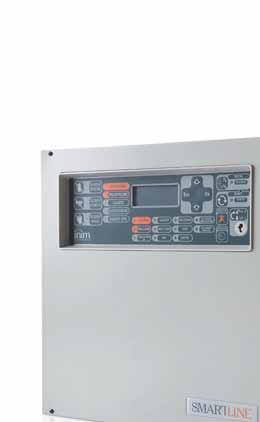


1 EN 54-2 EN 54-4 EN CPD CPD CPD-0230 SmartLine Conventional fire detection control panel Extinguishant system control panel User's manual
2 Chapter 1 Description of the Control panel 1.1 Manufacturer's name and address INIM Electronics s.r.l. Via Fosso Antico, Centobuchi Monteprandone (AP) - Italy Tel: Fax: info@inim.biz Device identifier Denomination: Conventional fire detection and extinguishing control panel Model: SmartLine 1.3 Copyright The information contained in this document is the sole property of INIM Electronics s.r.l. No part may be copied without written authorization from INIM Electronics s.r.l. All rights reserved. 1.4 In-box documentation User's manual (this manual) Installation and programming manual 1.5 Manual details Title: SmartLine user's manual Edition, Issue: 3.00 Month and year: May 2011 User manual code: DCMUINE0SLINE 1.6 Control panel user Interface G H X Y A1 B1 C1 D1 J A C D K L I Z E1 N T M O P S Q R W U V E F B Figure 1 - Control panel frontplate 2 Description of the Control panel
3 1.6.1 Commands Note: For further details refer to the Installation Manual, paragraph 5.1 SmartLine panel frontplate. Command Access level 1 Access level 2 [A] Navigation keys [B] Keyhole for the access level 2 key Key not inserted or inserted in vertical position Key inserted in horizontal position [C] SILENCE Push this button to silence (turn off) the panel beeper. Silences (turns off) active outputs with the silenceable attribute. The silenceable outputs will hold silenced status until a new event occurs that will release the outputs automatically. The SILENCE button operates as a toggle switch, therefore, silenced outputs can be unsilenced by pushing the button again. [D] RESET Push this button to clear any active events, delete the memory and restore standby conditions. [E] EVACUATE If this button is pressed during active pre-alarm conditions, the system will override the programmed pre-alarm time and generate an instant alarm (i.e. activate all evacuation-warning devices). If this button is pressed when pre-alarm conditions are not active, the system will generate a panel alarm. [F] INVESTIGATE If this button is pressed during active pre-alarm conditions, the system will add the preset investigation time to the running pre-alarm time (this operation can be done once only). Extinguishant module (accessory item) commands [G] DISABLE EXTINGUISH If this button is pressed once, the system will disable Extinguish commands. If this button is pressed again, the system will re-enable Extinguish commands. [H] DISABLE AUTO If you push this button once, the system will disable automatic extinguish commands generated by the Extinguishant module. If you push this button again, the system will re-enable automatic extinguish commands generated by the Extinguishant module. [I] DISABLE MANUAL If you push this button once, the system will disable manual extinguish commands. If you push this button again, the system will re-enable manual extinguish commands Signaling LED On solid: Blinking: [J] [K] [L] Display SILENCED RESET INHIBITED Indicates that the system has been silenced. In the event of pre-alarm/alarm, indicates that reset commands are not allowed. Reset will be allowed when all outputs have been silenced and this LED goes off. Description of the Control panel 3
4 LED On solid: Blinking: [M] ALARM (red) Indicates an alarm condition, that is, an input point (detector, callpoint, input module, etc.) set to generate alarms has detected alarm conditions. [N] PRE-ALARM (red) Indicates a pre-alarm condition, that is, an input point (detector, callpoint, input module, etc.) set with a pre-alarm time has activated. [O] FAULT Indicates an active fault condition. The display will provide the fault details. Indicates a restored fault condition in memory. To view the restored fault condition details, consult the events log using the Main menu (level 1). [P] CPU FAULT Indicates trouble with the panel CPU; the panel must be sent back immediately to the manufacturer for repair. Indicates that the CPU re-initialized (due to control panel shutdown or fault condition). [Q] DISABLED Indicates that one (or more) of the system components (zones or outputs) has been bypassed. [R] TEST Indicates that one or more components (points or zones) is undergoing tests. [S] ON (green) Indicates that the system is operating (on). [T] DIALLER ON (red) Indicates that the dialler activation output is active. [U] DISABLE/ FAULT DIALLER Indicates that the dialer activation output is disabled or faulty the display will provide the respective details. Indicates restoral of a fault event. This condition can be cleared by reset only (level 2). [V] DISABLE/ FAULT BELLS Indicates that the sounder/flasher activation output is disabled or faulty the display will provide the respective details. Indicates restoral of a fault event. This condition can be cleared by reset only (level 2). [W] NIGHT MODE Indicates that the panel is operating in night mode. [X] [Y] [Z] DISABLE EXTINGUISH DISABLE AUTO DISABLE MANUAL Extinguishant module signaling (optional system enhancement tool) Indicates disablement of all types of extinguish commands, via key [G] (refer to the previous table Commands). Indicates disablement of automatic extinguish commands, via key [H] (refer to the previous table Commands). Indicates disablement of manual extinguish commands, via key [I] (refer to the previous table Commands). [A1] EXTINGUISH Indicates that fire extinction is running. [B1] PRE- EXTINGUISH Indicates that the pre-extinction output is active. Indicates that only one zone is in alarm status, therefore, the extinguishant system will not be activated. If another zone latches in alarm, the extinguishant system will be activated. [C1] FAULT Indicates trouble with the fire extinction circuits. Indicates restoral of a fault event. [D1] STOP EXTINGUISH Indicates that the fire-extinction process has been interrupted by means of a remote Hold-off unit. Indicates restoral of a Stop extinction event. [E1] CPU FAULT Indicates a CPU fault that requires immediate repair. Indicates restoral of a fault event. 4 Description of the Control panel
5 1.7 Repeater This control panel supports up to four repeater panels. Connected repeater panels replicate all the information provided by the control panel and allow access to all Level 1 and 2 functions (View active events, Reset, Silence, etc.), but do not allow access to the Main menu. A K M V Y L N W Z O R X Z1 P S Q T U G F J E H C I D B Figure 2 - Front view of the repeater panel The SmartLetUSee/LCD repeater is supported by most control panel models. However, when it is connected to a SmartLine control panel, some of the command buttons are not operational. The following keys/ buttons will work: [A] Navigation keys Scroll keys which will allow navigation through menus, etc. [B] EVACUATE As per paragraph Commands [C] SILENCE As per paragraph Commands [D] RESET As per paragraph Commands [E] INVESTIGATE As per paragraph Commands [F] BUZZER Turns the panel beeper off [G] TEST Turns on al the LEDs to verify functionality. Repeaters provide the following signals Display The display provides same event data as the panel. For further details refer to paragraph 2.5 Signaling on the display. Description of the Control panel 5
6 1.7.2 LEDs LED On solid: On blinking: [H] SILENCED As per paragraph Commands [I] RESET DISABLED As per paragraph Commands [J] INVESTIGATE Indicates that investigation time has been requested. [K] ALARM As per paragraph Commands [L] PRE-ALARM As per paragraph Commands [M] FAULT As per paragraph Commands [N] CPU FAULT Indicates that the repeater CPU is faulty (it must be sent back to the manufacturer for repair) or that there is no communication with the control panel (check the connections). Indicates that the control panel CPU has been reset. [O] DISABLED As per paragraph Commands [P] TEST As per paragraph Commands [Q] NIGHT MODE As per paragraph Commands [R] BATTERY Indicates that the panel batteries are low or inefficient. Indicates restoral of the low/ inefficient battery event. [S] EARTH Indicates voltage dispersion to earth. Indicate restoral of the voltage dispersion to earth event. [T] FUSE Indicates that either the AUX or AUX-R output is shorted and the protection fuse has intervened. Indicates the restoral of AUX or AUX- R output-shorted event. [U] MAINS Indicates Mains failure. Indicates restoral of the Mains failure event. [V] BELLS - ACTIVE Indicates that the ALARM NAC output is active. [W] BELLS - FAULT Indicates that a fault has been detected on the ALARM NAC output. Indicates restoral of the ALARM output fault. [X] BELLS - DISABLED Indicates that the ALARM NAC output has been disabled. [Y] DIALLER - ACTIVE Indicates that the DIALER output is active. [Z] DIALLER - FAULT Indicates a DIALER output fault. Indicates restoral of the Dialer output fault. [Z1] DIALLER - DISABLED Indicates that the DIALER output has been disabled. 6 Description of the Control panel
7 Chapter 2 Using the Control Panel 2.1 For authorized persons Attention: Insert and turn the key. The panel will enable access level 2. The panel will hold level 2 status for 30 seconds. 2.2 Danger signaling Note: In the event of fire hazard, always follow the fire department approved fire drill For building occupants ALARM LED on PRE-ALARM LED on Evacuate the building immediately. In the event of real danger, press the EVACUATE button to broadcast the alarm and evacuate the building immediately. Or, if you consider evacuation to be an unnecessary measure, inform the person/s in charge of the safety of the building and its occupants immediately. To silence the beeper, press SILENCE For authorized persons To force the panel into alarm status, regardless of its status, press EVACUATE. ALARM/PRE- ALARM/RESET LED on At least one zone is in alarm/pre-alarm status: 1. If there is no intervention during a pre-alarm, the panel will generate an alarm when the pre-set pre-alarm time expires. 2. To request investigation time, press INVESTIGATE and check the building. Investigation time cannot be refreshed. 3. In the event of a false alarm, press SILENCE. The panel beeper and the silenceable outputs will be silenced until a new event occurs. If the panel is operating in Night mode, the panel beeper and the silenceable outputs will be unsilenced automatically after the pre-set time, and the panel will generate pre-alarm status. 4. If you wish to re-activate pre-alarm/alarm status after pressing the SILENCE button, press the SILENCE button again: pre-alarm/alarm signaling and the outputs will re-activate. 5. To clear all alarm/fault signaling and the memory, press RESET. If the conditions persist, the panel will generate another alarm. SILENCED LED on RESET LED on Indicates that the control panel has been silenced but has not yet been reset. The control panel is in alarm or pre-alarm status, you must press SILENCE before pressing RESET. Using the Control Panel 7
8 2.3 Fault signaling For building occupants FAULT LED on solid or blinking Inform security personnel immediately For authorized persons You must always ensure that faults are dealt with and cleared as soon as possible. However, in the meantime, you can bypass the zone/point/output concerned. FAULT LED on ON LED off CPU FAULT LED on DISABLE/FAULT DIALLER LED on DISABLE/FAULT DIALLER LED on Indicates at least one system fault condition. View the fault details on the display and ensure that it is dealt with and cleared. Indicates no mains or battery power supply. The system is not working, ensure that power is restored as soon as possible. The control panel is not operating properly and must be sent back to the manufacturer for repair. The dialler output is disabled or faulty. View the details on the display. Press RESET to turn off the LED. The Alarm NAC output is disabled or faulty. View the log details on the display. Press RESET to turn off the LED. 2.4 Informative signaling Signaling that does not require specific action. NIGHT MODE LED on The control panel is operating in night mode. Attention: The panel may have been programmed to generate instant alarms. During Night mode, SILENCE will be held for the pre-set silence time only. FAULT LED blinking DISABLE/FAULT BELLS LED blinking DISABLE/FAULT DIALLER LED blinking CPU FAULT LED blinking DISABLED LED on TEST LED on DIALLER ON LED on ON LED on Restoral of a system fault. View the log details on the display. Press RESET to turn off the LED. The ALARM NAC output fault has been cleared. View the log details on the display. Press RESET to turn off the LED. The Dialler output has signaled a fault and has restored. View the log details on the display. Press RESET to turn off the LED. The CPU has reset (due to control panel shutdown or jamming). Check the efficiency of the entire system. Press RESET to turn off the LED. A zone, point or output has been bypassed. View the details on the display. A zone or point is undergoing tests. View the details on the display. An alarm event has activated the dialler. CONTROL PANEL on. Viewing events The events represent the various conditions signaled by the panel and have the following order importance: alarm, pre-alarm, fault, early warning, bypass, test and monitor. The system displays information regarding real-time events of major importance and disregards those of minor importance (e.g.: if the system is dealing with three fault events when a pre-alarm event occurs, the fault events will be disregarded and cleared from the display and the pre-alarm will take priority). All events are saved to the log and can be viewed. 8 Using the Control Panel
9 2.5 Signaling on the display If several events of the same type occur, only the first will be shown on the display. If several alarms occur, the first alarm will remain on the first line of the display and the most recent alarm will be shown on the line below. Use the / keys to scroll the events on the display Alarm signaling Example of first alarm: a detector belonging to zone 02 goes into alarm status 1st line: number of the first zone to go into alarm status Alarm Z02 2nd line: description of the first zone to go into alarm status <Zone Descr. 02> 3rd line: - TOT. 001 ON 01 Z 4th line: total numbers of alarm events and total number of zones in alarm status. Example of successive alarm: a detector belonging to zone 29 goes into alarm status The total number of alarm events and zones involved will increase, however, the display will still show the details of the first alarm. Alarm Z02 <Zone Descr. 02> Fire alarm Z29 TOT. 002 ON 02 Z 1st line: unchanged 2nd line: unchanged 3rd line: number of the zone in alarm status 4th line: total number of alarm events and total number of zones in alarm status Example of several alarm event on the same zone: a callpoint connected to the Line I/O of the zone 29 goes also into alarm status Alarm Z02 <Zone Descr. 02> Fire alarm Z29 TOT. 003 ON 02 Z To view the alarm event details: 1st line: unchanged 2nd line: unchanged 3rd line: number of the zone in alarm status 4th line: total number of alarm events and total number of zones in alarm status Press the / keys; the details of the first alarm in zone 2 will be shown: Alarm Z02 <Zone Descr. 02> Las Z 29 TOT.02Z 1st line: number of the zone into alarm status 2nd line: description of the zone in alarm status 3rd line: - 4th line: number of the last zone and total zones in alarm status If no key is pressed within 20 seconds, the display will restore to the original template Pre-alarm, Early Warning and Monitor signaling Signaling is the same for these three event types, however, Monitor signaling is not associated with zones. Example of first pre-alarm event: a detector belonging to zone 02 goes into alarm status. Pre-alarm 01/01 Zone 02 <Zone Descr. 02> 1st line: pre-alarm event number and total number of pre-alarms 2nd line: number of the point in pre-alarm status 3rd line: description of the point in pre-alarm status Using the Control Panel 9
10 Example of successive pre-alarm event: User s manual The total number of pre-alarm events will increase but the display will still show the details of the first prealarm event. Pre-alarm 01/02 Zone 02 <Zone Descr. 02> 1st line: pre-alarm event number and total number of pre-alarms 2nd line: unchanged 3rd line: unchanged To view the pre-alarm events: 4th line: unchanged Press for the successive pre-alarm event. Press for the previous pre-alarm event. Pre-alarm 02/02 Zone 03 <Zone Descr. 03> 1st line: pre-alarm event number and total number of pre-alarms 2nd line: number of the zone in pre-alarm status 3rd line: description of the zone in pre-alarm status Fault signaling Fault signaling can be generated by a zone, or by the dialler, alarm NAC, fault NAC, 24V external loads outputs or by an anomalous condition found by the control panel. Example of first fault: fault on NAC output. Fault 01/01 SHORTED I/O Panel NAC 1st line: progressive number of the fault event and total number of fault events 2nd line: fault type 3rd line: output description Example of a successive fault: The total number of faults will increase but the display will still show the details of the first fault event. Fault 01/02 SHORTED I/O Panel NAC 1st line: progressive number of the fault event and total number of fault events 2nd line: unchanged 3rd line: unchanged To view the fault events: Press for the successive fault event. Press for the previous fault event. Fault 02/02 Ground fault 1st line: progressive number of the fault event and total number of fault events 2nd line: fault type 3rd line: - 10 Using the Control Panel
11 2.5.4 Bypassed and Test Signaling Bypassed signaling can be generated by a zone or an output. Test signaling can be generated only by a zone. Example of first bypassed zone event: zone 12 bypassed. Bypass 01/01 <Zone Descr. 12> 1st line: number of the first bypassed zone and total number of bypassed zones 2nd line: description of the bypassed zone 3rd line: - Example of a successive bypassed zone: The total number of bypassed zones will increase but the display will still show the details of the first bypassed zone event. Bypass 01/02 <Zone Descr. 20> 1st line: number of the first bypassed zone and total number of bypassed zones 2nd line: unchanged 3rd line: - To view all bypassed zones: Press for the successive bypassed zone. Press for the successive previous zone. Bypass 02/02 <Point Descr. 12> 1st line: number of the first bypassed zone and total number of bypassed zones 2nd line: description of the bypassed zone 2.6 View Events Log 3rd line: - Press any key, View log, Ok: all the recorded events will be shown in chronological order (maximum 100 events). 100 Alarm <Zone Descr. nn> 10/09/06 8:00 1st line: progressive number of the last event 2nd line: zone description 3rd line: 4th line: date and time Press / to scroll the log. Test Panel LEDs Press any key, Test LED, Ok; all the panel LEDs will go on briefly. Using the Control Panel 11
12 ISO 9001:2008 Registered Company via Fosso Antico Loc. Centobuchi Monteprandone (AP) ITALY Tel _ Fax info@inim.biz _ DCMUINE0SLINE-R
SmartLight Analogue fire alarm control panel Extinguishant system control panel Installation and programming manual CPR CPR-0223
 EN 54-2 EN 54-4 EN 12094-1 0051 0051-CPR-0222 0051-CPR-0223 SmartLight Analogue fire alarm control panel Extinguishant system control panel Installation and programming manual Analogue fire alarm control
SmartLoop Analogue fire alarm control panel Alarm transmission and fault warning routing equipment with integrated power supply equipment
 EN 54-2 EN 54-4 EN54-21 0051 0051-CPR-1415 0051-CPR-1416 0051-CPR-1417 0051-CPR-1418 0051-CPR-1419 0051-CPR-1420 SmartLoop Analogue fire alarm control panel Alarm transmission and fault warning routing
MANUAL FOR SYSTEM CONFIGURATION, COMMISSIONING AND MAINTENANCE. Configuration EN 54-2 manual
 Configuration EN 54-2 manual EN 54-4 EN 54-21 EN 12094-1 0051 0051-CPR-1498 0051-CPR-1499 ANALOG-ADDRESSABLE FIRE ALARM CONTROL PANEL, EXTINGUISHANT SYSTEM CONTROL PANEL, ALARM TRANSMISSION AND FAULT WARNING
Installation and Programming manual INSTALLATION MANUAL E PROGRAMMING INSTALLAZIONE PROGRAMMAZIONE
 SELF-POWERED S I R E N A A U SOUNDER/FLASHER T O A L I M E N T A T A FOR P E R OUTDOOR E S T E R NUSE O INSTALLATION MANUALE AND DI PROGRAMMING INSTALLAZIONE MANUAL E PROGRAMMAZIONE 1 Table of contents
NRB100. Installation and Programming Manual INSTALLATION NRB100 AND PROGRAMMING MANUAL
 S E L F - P O W E R E D H O R N S T R O B E F O R O U T D O O R U S E INSTALLATION AND PROGRAMMING MANUAL 1 Table of contents Table of contents............................... 2 Chapter 1 Overview...........................
6100 SINGLE LOOP DIGITAL ADDRESSABLE FIRE ALARM CONTROL PANEL
 6100 SINGLE LOOP DIGITAL ADDRESSABLE FIRE ALARM CONTROL PANEL USER MANUAL Protec Fire Detection plc, Protec House, Churchill Way, Nelson, Lancashire, BB9 6RT. Telephone: +44 (0) 1282 717171 Fax: +44 (0)
Intelligent Security & Fire Ltd
 full installation, commissioning and operating manuals can be downloaded from www.haes-systems.co.uk combined addressable / conventional fire alarm control panel User Guide Approved Document No. MFBU-04
Watchguard WGAP864 User Manual
 Watchguard WGAP864 User Manual v1.0 Issued September 2016 1 2 Table of Contents Glossary... 5 1. Introduction to your Watchguard WGAP864... 6 2. Before Operating your Alarm System... 6 3. Understanding
The complete R&TTE Declaration of Conformity for each Panel can be found at
 USER GUIDE FC200 - FC200/S - FC200/SL - FC100: Hereby, Bentel Security, declares the above mentioned Control Panels to be in compliance with the essential requirements and other relevant provisions of
ZX1e ZX2e ZX5e. Document No Issue 01 user manual
 ZX1e ZX2e ZX5e Document No. 996-130 Issue 01 user manual MORLEY-IAS ZX2E/ZX5E Fire Alarm Control Panels Table of Contents 1 INTRODUCTION... 4 1.1 NOTICE... 4 1.2 WARNINGS AND CAUTIONS... 4 1.3 NATIONAL
Ref. 1067/024 Ref. 1067/032A Ref. 1067/052A
 DS1067-062C Mod. 1067 LBT20063 REMOTE CONTROLLABLE ALARM CONTROL PANELS Ref. 1067/024 Ref. 1067/032A Ref. 1067/052A USER MANUAL TABLE OF CONTENTS INTRODUCTION... 6 1 CONTROL DEVICES... 7 1.1 1067/022 keypad
USER MANUAL COMBINED FIRE & EXTINGUISHING CONTROL PANEL COMPLIES WITH BS EN PART 1 & EN54 PARTS 2 & 4
 PREMIER EX8 EXTINGUISHING PANEL USER MANUAL COMBINED FIRE & EXTINGUISHING CONTROL PANEL COMPLIES WITH BS EN 12094 PART 1 & EN54 PARTS 2 & 4 USER MANUAL Approved Document No: GLT.MAN-132 INDEX Extinguishing
BSR Addressable Fire Detection control panel. Installation operation manual
 BSR-1116 Addressable Fire Detection control panel Installation operation manual ATTENTION!!! READ THE MANUAL BEFORE THE INSTALLATION AND PAY ATTENTION TO PARAGRAPH 2.6.3 AND 2.6.4. Page 2 from 36 Contents
SmartLoop Analogue fire alarm control panel Installation manual
 EN 54-2 EN 54-4 0051 0051-CPR-0225 0051-CPR-0226 0051-CPR-0227 0051-CPR-0228 0051-CPR-0231 0051-CPR-0232 SmartLoop Analogue fire alarm control panel Analogue fire alarm control panel Copyright The information
user manual Document No , Revision 03 November 2015
 user manual Document No. 996-202-600-3, Revision 03 November 2015 Contents 1 Introduction...1 1.1 Notice...1 1.2 Models...1 2 User Control Levels...2 2.1 Level Definition...2 2.2 User Passwords...2 3 Controls
FA-300 Series. LED Fire Alarm Control Panel. User Guide. FA-300 SERIES Fire Alarm Control Panel. FA-300 SERIES Fire Alarm Control Panel
 LAMP TEST REMOTE CPU FAULT GROUND FAULT SIGNAL SILENECE FIRE DRILL BUZZER SILENCE INFO AC ON ALARM SUPERVISORY BATTERY SYSTEM RESET AUXILIARY DISCONNECT LAMP TEST MENU LAMP TEST REMOTE CPU FAULT GROUND
User Operation Manual
 APPROVED BY: JBJ PRESCIENT III FIRE ALARM & GAS EXTINGUISHING CONTROL PANEL User Operation Manual PAGE 1 of 6 1 CONTENTS 1. FIRE - GENERAL... 3 2. FIRE - ZONES 1 OR 2 - AUTOMATIC MODE... 3 3. FIRE - ZONES
Saffire User & Installation Manual. IMPORTANT This manual should be left with the panel after installation.
 Saffire+ 8-12 User & Installation Manual IMPORTANT This manual should be left with the panel after installation. We reserve the right to change product specifications without prior notice. Copyright VRC
3500 CONVENTIONAL FIRE ALARM CONTROL PANEL
 3500 CONVENTIONAL FIRE ALARM CONTROL PANEL USER MANUAL Protec Fire Detection PLC, Protec House, Churchill Way, Nelson, Lancashire, BB9 6RT. Telephone: +44 (0) 1282 717171 Fax: +44 (0) 1282 717273 Web:
BENTEL SECURITY srl reserves the right to modify the technical specifications of this product without prior notice.
 BENTEL SECURITY srl reserves the right to modify the technical specifications of this product without prior notice. via Florida - Z.I. Valtesino - 63013 GROTTAMMARE (AP) - ITALY USER MANUAL: Digital communicator
U ser's Guide PC6010
 User's Guide PC6010 Quick Reference Guide This manual is for Basic and Advanced users. Each of these types of user can access a different set of functions. The and symbols next to the title of each procedure
Fire Command Keypad. XR5 User s Guide
 Fire Command Keypad XR5 User s Guide Silencing an Alarm While the fire alarm horns, strobes, or sirens are sounding use one of the following methods to silence the alarm depending on which type of keypad
Security System. User s Guide for the Text Command Center
 User s Guide for the Text Command Center MY ALARM COMPANY IS: CALL BEFORE TEST: THIS SECURITY SYSTEM IS CONNECTED TO TELEPHONE NUMBER: THE SECURITY CONTROL PANEL IS CONNECTED TO THE PHONE JACK LOCATED:
Guide for the integration with supervision systems FIRE DETECTION AND EXTINGUISHANT SYSTEMS GUIDE FOR INTEGRATION WITH SUPERVISION SYSTEMS
 Guide for the integration with supervision systems FIRE DETECTION AND EXTINGUISHANT SYSTEMS GUIDE FOR INTEGRATION WITH SUPERVISION SYSTEMS 1 Fire detection and extinguishant systems Obligations of the
CSP-204 CSP-208 CSP-104 CSP-108
 Fire Alarm Control Panel CSP-204 CSP-208 CSP-104 CSP-108 Operation manual Firmware version 1.1 csp-x_o_en 06/15 SATEL sp. z o.o. ul. Budowlanych 66 80-298 Gdańsk POLAND tel. 58 320 94 00 www.satel.eu CONTENTS
Syncro AS. Analogue Addressable Fire Control Panel. User Manual
 Syncro AS Analogue Addressable Fire Control Panel User Manual Man-1100 Issue 02 Nov. 2008 Index Section Page 1. Introduction...3 2. Safety...3 3. Panel Controls...4 3.1 Access Level 1...4 3.2 Access Level
SFC-200 SERIES LED FIRE ALARM PANEL
 SFC-200 SERIES LED FIRE ALARM PANEL USER GUIDE LT-953SUM SFC-200 Series LED Version User Guide Contents Contents... i Introduction... 1 About this Manual... 1 Technical Support... 1 Main Display... 2
Section 9 System Operation
 Section 9 System Operation Operation of the control panel is simple. Menus guide you step-by-step through operations. This section of the manual is an overview of the operation menus. Please read this
3200 NON-ADDRESSABLE FIRE ALARM CONTROL PANEL
 3200 NON-ADDRESSABLE FIRE ALARM CONTROL PANEL USER MANUAL Protec Fire Detection PLC, Protec House, Churchill Way, Nelson, Lancashire, BB9 6RT. Telephone: +44 (0) 1282 717171 Fax: +44 (0) 1282 717273 Web:
ZSC100 Gas Detection and Alarm System Controller
 ZSC100 Gas Detection and Alarm System Controller User Guide 1- Introduction... 3 1.1- General description... 3 1.2- Cautions and warnings... 3 2- Control panel... 4 2.1 Control panel overview... 4 2.2
Matrix2000. User Guide - CPD Advanced Analog Fire Alarm Control Panel 4 24 Zones. Version: 2.0 Revision: 1
 Matrix2000 User Guide - CPD Advanced Analog Fire Alarm Control Panel 4 24 s Version: 2.0 Revision: 1 IMPORTANT INFORMATION Limitation of liability It is mandatory, Matrix2000 panel to be installed in accordance
Master Code Arming Auto-Bypass Option - Home-Away Arming Entry Delay Off Arming
 Master Code The 4 digit Master Code is used for arming and disarming the system, for programming additional access codes, and for changing other features. The Master Code will be supplied to you by your
ViewMatrix. Software for Online Monitoring & Control of Matrix2000 Conventional Fire Alarm Panels. Version: 2.0 Revision: 0.1
 ViewMatrix Software for Online Monitoring & Control of Matrix2000 Conventional Fire Alarm Panels Version: 2.0 Revision: 0.1 CONTENTS 1. Introduction...3 2. Keyboard...5 2.1 POWER indication - Normal Operation...5
Contents. Glossary Introduction to the IDS Notes Understanding the Keypad Indicators Operation of the Keypad...
 2 Contents Glossary...7 1. Introduction to the IDS805...8 1.1 Notes...8 2. Understanding the Keypad Indicators...8 3. Operation of the Keypad...9 4. System Information...10 4.1 Programmed Functions...10
Operator's Handbook. Interactive Fire Alarm System Release 3. Information Panel, BV-320. Protecting life, environment and property...
 Interactive Fire Alarm System Release 3 Operator's Handbook Information Panel, BV-320 Protecting life, environment and property... ASAFE-IN/FE Rev. A, 010531 COPYRIGHT This publication, or parts thereof,
Section 8 System Operation
 Section 8 System Operation Operation of the control panel is simple. Menus guide you step-by-step through operations. This section of the manual is an overview of the operation menus. Please read this
Laptop / PC Programming Manual
 Laptop / PC Programming Manual Doc. # Fire PC Program rev B 01.07 This Document is property of Evax Systems, Inc. The Evax Fire Solutions Programmer Components 2 1.0 System Setup 4 1.1 Interface Setup
User s Guide. SUB-MA7240O-0001.OG.Solution doc. Created: 6/05/03. Last Updated: 23/09/03. MA7240AO-0001 Version 1.0
 User s Guide SUB-MA7240O-0001.OG.Solution40-111.doc Created: 6/05/03 Last Updated: 23/09/03 MA7240AO-0001 Version 1.0 2 Table Of Contents User List...6 Quick Reference..7 Features...7 Keypad User's Guide...8
IDS800 USER MANUAL. Summary of Operation. + [ ] 2 IDS800 USER MANUAL NO K ISSUED APR 2003 VER 1.44
![IDS800 USER MANUAL. Summary of Operation. + [ ] 2 IDS800 USER MANUAL NO K ISSUED APR 2003 VER 1.44](/thumbs/89/98095999.jpg "IDS800 USER MANUAL. Summary of Operation. + [ ] 2 IDS800 USER MANUAL NO K ISSUED APR 2003 VER 1.44") Summary of Operation A rm/ disarm [#] + [USER CODE] Quick Quick Quick Away Arm Stay Arm Stay Arm & Go H old down [ 1] for 1 second H old down [ 5] for 1 second H old down [ 6] for 1 second Panic Fire Medical
Summary of Operation A rm/ disarm [#] + [USER CODE] Quick Quick Quick Away Arm Stay Arm Stay Arm & Go H old down [ 1] for 1 second H old down [ 5] for 1 second H old down [ 6] for 1 second Panic Fire Medical
user manual and log book XFP NETWORKABLE ANALOGUE ADDRESSABLE FIRE ALARM CONTROL PANEL
 XFP NETWORKABLE ANALOGUE ADDRESSABLE FIRE ALARM CONTROL PANEL f i r e s a f e t y e q u i p m e n t 8 Arkwright Court, Fylde Industrial Estate, Blackpool, Lancashire FY4 5DR. Sales Tel: 01253 699500 (Fax:
XFP NETWORKABLE ANALOGUE ADDRESSABLE FIRE ALARM CONTROL PANEL. user manual and log book. approved document no. DFU Rev 1
 XFP NETWORKABLE ANALOGUE ADDRESSABLE FIRE ALARM CONTROL PANEL user manual and log book approved document no. DFU2000501 Rev 1 CONTENTS Important safety notes...3 Introduction...4 Fire alarm systems - an
Contents. Glossary
 Contents Glossary ------------------------------------------------------------------------------------------------------ 6 1. Introduction to the IDS 1632 -------------------------------------------------------------
Version 1.03 January-2002 USER S MANUAL
 Version 1.03 January-2002 1 USER S MANUAL 2 Version 1.03 January-2002 System Details CUSTOMER:...... PHONE:... FAX:... INSTALLED BY:...... PHONE:... FAX:... MAINTENANCE & SERVICE:...... PHONE:... FAX:...
Operator s Manual Part: InfoAlarm Product: 4100U, 4100ES Rev. B
 Operator s Manual Part: InfoAlarm Product: 4100U, 4100ES 579-685 Rev. B ii iii Cautions and Warnings Cautions and Warnings READ AND SAVE THESE INSTRUCTIONS- Follow the instructions in this installation
Summit 3208GLD USER MANUAL. Electronics Line
 Summit 3208GLD USER MANUAL Electronics Line Table of Contents 1: Introduction... 2 2: Overview... 3 3: Keypad Functions... 4 3.1: Keypads... 4 3.2: 3108 LCD Keypad Layout... 4 4: Basic System Operation...
TABLE OF CONTENTS TABLE OF CONTENTS 1
 TABLE OF CONTENTS TABLE OF CONTENTS 1 FEATURES 2 Keypad Programmable... 2 EEPROM Memory... 2 Static/Lightning Protection... 2 Supervision... 2 Operation... 2 SPECIFICATIONS 2 PC1550 Control Panel... 2
The EN54 Part 2 and 4 Fire System
 Scope of work: To design, supply, install and commission a Fire Alarm Control System in accordance with the details specified herein and in accordance with supplied drawings The EN54 Part 2 and 4 Fire
Security System. User Guide for the LED Command Center
 Security System User Guide for the LED Command Center National Security Systems Inc (800)457-1999 MY SECURITY COMPANY IS: CALL BEFORE TEST: THIS SECURITY SYSTEM IS CONNECTED TO TELEPHONE NUMBER: THE SECURITY
Installation, Operating and Maintenance Manual
 STATUS ZONES CONTROLS FIRE FAULT DISABLED FIRE 1 2 3 4 5 6 7 8 TEST FAULT DISABLED 1 5 BUZZER SILENCE RESET 1 2 TEST 2 6 LAMP TEST 3 SUPPLY 3 7 SYSTEM FAULT 4 8 SOUNDERS ACTIVATE/ SILENCE 4 FAULTS INSTRUCTIONS
Operator's Handbook. Release 3. Fire Alarm Control Panel, BS-310 / 320 / Operator Panel BS-330. System Program Version 3.8.0
 Release 3 System Program Version 3.8.0 Operator's Handbook Fire Alarm Control Panel, BS-310 / 320 / Operator Panel BS-330 Protecting life, environment and property... ASAFE-FO/FE Rev. I, 2009-02-27 COPYRIGHT
Algo-Tec 6500/6600 INTERACTIVE ADDRESSABLE FIRE CONTROL SYSTEM
 Algo-Tec 6500/6600 INTERACTIVE ADDRESSABLE FIRE CONTROL SYSTEM (1-4 LOOPS) USER MANUAL Protec Fire Detection plc, Protec House, Churchill Way, Nelson, Lancashire, BB9 6RT, ENGLAND +44 (0) 1282 717171 www.protec.co.uk
Control/Communicator Installation Manual
 DAS NETWORX NX-12 Control/Communicator Installation Manual General Description...2 Ordering Information...2 Option Definitions...3 Programming the LED Code Pads...5 Programming the NX-12...9 Types of Programming
D8024, D9024, D10024 Analog Fire Alarm Control Panels Programming Guide
 System Reset Trou ble Silence Ala rm Silence Manual Ala rm ENTER NO YES Letters Numb ers Keyword Radionics System Reset Trouble Silence Alarm Silence Manual Alarm ENTER NO YES Le ters Numbers Keyw ord
AFP-300/400 OPERATORS MANUAL INTELLIGENT FIRE DETECTION AND ALARM SYSTEM SOFTWARE VERSION 2.2 REVISION AUS 3
 OPERATORS MANUAL AFP-300/400 INTELLIGENT FIRE DETECTION AND ALARM SYSTEM SOFTWARE VERSION 2.2 REVISION AUS 3 NSW (Head Office) 7 Columbia Court Norwest Business Park Baulkham Hills NSW 2153 Ph: (02) 9899-4155
Fire Command Center. XR2400F User s Guide
 Fire Command Center XR2400F User s Guide Silencing an Alarm While the fire alarm horns, strobes, or sirens are sounding use one of the following methods to silence the alarm. 1. Turn the keyswitch to enable
IDS816 User Manual H Issued January 2009
 1 Contents Glossary-------------------------------------------------------------------------------------------------------------------6 1. Introduction to the IDS 816---------------------------------------------------------------------------7
CONTENTS Installation Precautions... 1 Chapter 1 Product Introduction... 2 Chapter 2 Technical Specifications... 3
 CONTENTS Installation Precautions... 1 Chapter 1 Product Introduction... 2 Chapter 2 Technical Specifications... 3 2.1 Electrical Specifications... 3 2.2 Communication Loop Parameters... 3 2.3 Dimensions...
Operating instructions SENTRI4 Control panel based Fire detection and alarm system
 1 2 3 4 5 6 7 8 9 10 11 12 13 14 15 16 17 18 19 20 21 22 23 24 25 26 27 28 29 30 30 32 Zones Healthy 15:45 Fault Power Fault System Fault SenTRI 4 Fire System Designed to EN54 Pt 2 & 4 Operating instructions
USER MANUAL & MAINTENANCE GUIDE OG OO
 M+48. USER MANUAL & MAINTENANCE GUIDE OG OO What to do if the Fire Alarm Panel shows an Alarm (Red LED) Write down which LEDs are lit (either in the log book, or on a piece of paper for transferring to
PNC 1000 SERIES 2, 4, 8 Zone Fire Alarm Control Panel
 PNC 1000 SERIES 2, 4, 8 Zone Fire Alarm Control Panel INSTALLATION, OPERATION AND MAINTENANCE MANUAL Version: CN-PM-1000.VER1.1-12/2012 EN54 INFORMATION In accordance with EN 54-2 clause 13.7, the maximum
AXI LED USER MANUAL (REV. 1.0)
") Security & Home Automation System AXI LED USER MANUAL (REV. 1.0) CONTENTS PREFACE FEATURES LED KEYPAD OUTLOOK 1.0 LIGHT INDICATION 1 2 4 6 CHAPTER 1: ALARM SYSTEM CONTROL 1.0 USING LED KEYPAD 1.0.1 ARMING
Security & Home Automation System AXI LED USER MANUAL (REV. 1.0) CONTENTS PREFACE FEATURES LED KEYPAD OUTLOOK 1.0 LIGHT INDICATION 1 2 4 6 CHAPTER 1: ALARM SYSTEM CONTROL 1.0 USING LED KEYPAD 1.0.1 ARMING
HARDWIRED CONTROL PANELS
 USER GUIDE 9651 HARDWIRED CONTROL PANELS Contents 1. Introduction...3 The Alarm System...3 The Keypad...3 About This Guide...5 2. Everyday Operation...6 How Do I Know if the System is Working?...6 Setting
Ref.1067/032 Ref.1067/042
 DS1067-033A Mod. 1067 LBT8631 BUS CONTROL PANEL 8/32 INPUTS Ref.1067/032 Ref.1067/042 USER MANUAL TABLE OF CONTENTS 1 PREFACE... 5 2 COMMAND DEVICES... 6 2.1 1067/021 DISPLAY KEYPAD... 6 2.2 ELECTRONIC
SmartLoop. Analogue Fire Alarm Control Panel. Installation manual. GameOver
 SmartLoop Analogue Fire Alarm Control Panel Installation manual GameOver Copyright The information contained in this document is the sole property of Inim Electronics s.r.l. No part may be copied without
Area Systems While the alarm bell or siren is sounding, enter your user code. The system silences the alarm bell or siren.
 XR20 User s Guide Silencing an Alarm All/Perimeter and Home/Away Systems While the alarm bell or siren is sounding, enter your user code. The keypad displays DISARM SILENCE. Press the Select key under
Document No Issue 4 user manual
 DX Document No. 996-148-000-4 Issue 4 user manual Dimension Series Table of Contents 1 INTRODUCTION... 5 1.1 NOTICE... 5 1.2 MODELS... 5 1.3 WARNINGS AND CAUTIONS... 7 1.4 NATIONAL APPROVALS... 7 1.5 EN54
Ref. 1067/024 Ref. 1067/032A Ref. 1067/052A
 DS1067-064D Mod. 1067 LBT20065 REMOTE CONTROLLABLE ALARM CONTROL PANELS Ref. 1067/024 Ref. 1067/032A Ref. 1067/052A PROGRAMMING MANUAL TABLE OF CONTENTS INTRODUCTION... 7 1 CONTROL DEVICES... 8 1.1 1067/022
User s Information Guide R2A
 Pi HSC505 Home Security Controller User s Information Guide R2A Page 1 of 15 of its development program. 1This document and product are copyrighted and all rights are reserved. Introduction Convention
NX-148 LCD CODE PAD TABLE OF CONTENTS
 NX-148 LCD CODE PAD TABLE OF CONTENTS Glossary Of Terms... 4 Understanding The Lights... 5 Code Pad Functions Arming In The ON Mode... 6 Making The System Ready To Arm... 7 Using Quick Arm... 7 Arming
BENTEL SECURITY reserves the right to modify the technical features of this product without prior notice.
 BENTEL SECURITY reserves the right to modify the technical features of this product without prior notice. via Florida Z.I. Valtesino - 63013 GROTTAMMARE (AP) - ITALY Installation and Quick guide: DUAL
ZM2 OPERATING AND MAINTENANCE INSTRUCTIONS
 ZM2 OPERATING AND MAINTENANCE INSTRUCTIONS CONTENTS 1. System Overview 2. User responsibilities 3. First Line controls and indications 3.1 Logging on to the fire alarm system 3.2 Checking system status
D1265. User's Guide. Touchscreen Keypad
 D1265 EN User's Guide Touchscreen Keypad D1265 User's Guide Contents This system includes a telephone line seizure feature. The system can be programmed to communicate with a central monitoring station
USER GUIDE HARDWIRED CONTROL PANELS
 USER GUIDE HARDWIRED CONTROL PANELS Scantronic Contents 1. Introduction... 3 The Alarm System... 3 The Keypads... 3 The 725r Remote Setting Device... 6 About This Guide... 6 2. Everyday Operation... 7
INTELLIGENT FIRE TECHNOLOGY. Twinflex and Multipoint V3. User Guide (TO BE RETAINED BY USER) Issue 3
 Issue 3") INTELLIGENT FIRE TECHNOLOGY Twinflex and Multipoint V3 User Guide (TO BE RETAINED BY USER) 26-0340 Issue 3 Rafiki Protection Limited Rafiki policy is one of continual improvement and the right to change
INTELLIGENT FIRE TECHNOLOGY Twinflex and Multipoint V3 User Guide (TO BE RETAINED BY USER) 26-0340 Issue 3 Rafiki Protection Limited Rafiki policy is one of continual improvement and the right to change
BENTEL SECURITY declines all responsibility in the event of unauthorized intervention on the FireClass200 control panel.
 V4.2 BUI 0.1 061099 The FireClass200 is available in the following models: FC200 - Master panel with 4 A Linear power supply; FC200/S - Master panel with 2.5 A Switching power supply; FC200/SL - Slave
Installation and user manual for the CF5000, MF5000 and FXP5000 range of fire panels
 CF5000, MF5000 and FXP5000 Installation and user manual for the CF5000, MF5000 and FXP5000 range of fire panels 16 zone panels Contents PANEL INSTALLATION...3 Installation...3 PANEL WIRING... 3 Mains power
FIRE ALARM CONTROL PANEL FVC01-08
 FIRE ALARM CONTROL PANEL FVC01-08 USER MANUAL, MAINTENANCE GUIDE & LOG BOOK Radal Technology Limited Unit 1, Webber Court Billington Road, Burnley Lancashire, BB11 5UB Tel: +44 (0) 1282 463 770 Fax: +44
NetworX Series. NX-8 Commercial Fire Panel Installation and Startup
 NetworX Series NX-8 Commercial Fire Panel Installation and Startup 2004 GE Security All rights reserved. Printed in the United States of America. These instructions do not purport to cover all details
MMX TM. Intelligent Fire Alarm Network. User Guide
 MMX TM Intelligent Fire Alarm Network User Guide LT-893SEC Rev 1 May 2017 MMX TM User Guide Table of Contents Introduction... 1 About this Manual... 1 Front Panel Indicators, Controls, and Operation...
PANELS, KEYPADS & MODULES. Take Fire Protection to the Next Level Fire Products from DSC
 Take Fire Protection to the Next Level Fire Products from DSC AFD2000 Addressable Fire Control Panel Series Provides Maximum Flexibility The new AFD2000 is a completely programmable series of addressable,
Scimitar user manual & log book. Petersfield Business Park, Bedford Rd, Petersfield, Hampshire GU32 3QA Tel: Fax:
 Petersfield Business Park, Bedford Rd, Petersfield, Hampshire GU32 3QA Tel: 01730 268 231. Fax: 01730 265 552 Scimitar user manual & log book SCIMITAR USER MANUAL Approved Document No. DFU7001001 Rev 2
Control Panel User Guide (TO BE RETAINED BY THE USER)
") Fire Detection & Alarm System Control Panel V3 (Suitable for Quadnet control panels from V2.00) Control Panel User Guide (TO BE RETAINED BY THE USER) 26-0585 Issue 7 Fike s policy is one of continual improvement
Fire Detection & Alarm System Control Panel V3 (Suitable for Quadnet control panels from V2.00) Control Panel User Guide (TO BE RETAINED BY THE USER) 26-0585 Issue 7 Fike s policy is one of continual improvement
DS9400 Series. Release Notes for Firmware V2.07. Fire Alarm Control Panel
 DS9400 Series EN Release Notes for Firmware V2.07 Fire Alarm Control Panel DS9400 Series Release Notes for Firmware V2.07 Trademarks Trademarks Gentex is a trademark of Gentex Corporation, Fire Protection
JUNO-NET. Fire Alarm Control Panel OPERATION & MAINTENANCE MANUAL
 Fire Alarm Control Panel & MANUAL CONTENTS SECTION -. Description of the fire control panel fascia.... Alarm.... Reset the system.... Sound and silence the alarms.... Read the Fire, Fault, Test and Disabled
Table of Contents. Appendix A Special Characters 31
 Table of Contents Introduction 2 Section 1: General System Operation 3 1.1 Getting to Know Your System... 3 1.2 How to Arm... 4 1.3 Alternate Arming Methods... 5 1.4 Disarming... 6 1.5 Alarm Memory...
To operate the 5207 you can use either the built-in touchpad or the Model 5230 Remote Annunciator.
 Section 5 Operation To operate the 5207 you can use either the built-in touchpad or the Model 5230 Remote Annunciator. Figure 5-1 Built-in Touchpad (Seven-Segment Display) Figure 5-2 Model 5230 Remote
TABLE OF CONTENTS. FOR THE RECORD 15 PROGRAMMING WORK SHEETS 16 CONTROL PANEL WIRING DIAGRAM inside back cover
 TABLE OF CONTENTS FEATURES 2 SPECIFICATIONS 2 INSTALLATION 3 Mounting the Panel... 3 Mounting the Keypad... 3 Auxiliary Power Connection... 3 PGM Terminal Connections... 3 Bell/Siren Connection... 3 Keypad
FIRE CONTROL PANEL. Revision 1.1 January 1997 USER MANUAL. Emergi-Lite Safety Systems Ltd Bruntcliffe Lane Morley Leeds LS27 9LL
 FIRE CONTROL PANEL Revision 1.1 January 1997 USER MANUAL Emergi-Lite Safety Systems Ltd Bruntcliffe Lane Morley Leeds LS27 9LL Tel: 0113 281 0600 Fax: 0113 281 0601 C O N T E N T S PAGE INTRODUCTION...
SILENCING AN ALARM When the alarm bell or siren is sounding, enter your user code or present your SecuraProx fob to your keypad.
 SYSTEM USER GUIDE SILENCING AN ALARM When the alarm bell or siren is sounding, enter your user code or present your SecuraProx fob to your keypad. IS THIS A FALSE ALARM? YES NO displays. REAL ALARM If
Control Panel User Guide
 Fire Detection & Alarm System Control Panel V4.14 Control Panel User Guide (TO BE RETAINED BY USER) 26-0397 Issue 6 Fike s policy is one of continual improvement and the right to change a specification
DEFA HOME. User Manual Base Unit PRO
 DEFA HOME User Manual Base Unit PRO Table of Contents Overview 5 Logging into the app 9 Home 10 Calendar 13 Adding an event 14 Editing an event 15 Zones 16 Switch mode 17 Thermostat mode 19 Regulator
Intelligent Security & Fire Ltd
 Product Data Sheet Mx-4000 Series User Manual MX-4100, MX-4200, MX-4400, Mx-4400/LE & Mx-4800 Fire Alarm Control Panels The operation and functions described in the manual are available from Software Versions
Operating manual and Log book for the range of 1,2,4 and 8 zone fire Control and Repeat panels
 Operating manual and Log book for the range of 1,2,4 and 8 zone fire Control and Repeat panels The panels are designed in accordance with the requirements of EN54 Part 2:1997 (and include optional clauses
Installation and user manual for the FX range of fire panels. 1, 2, 4 and 8 zone panels
 Installation and user manual for the FX range of fire panels 1, 2, 4 and 8 zone panels Contents Panel installation 3 Panel connections 3 Wiring connection drawings 4 Panel facilities 6 Installation check
EasyTronic III MANUAL SERVICE
 rev.6 EasyTronic III MANUAL SERVICE General characteristics: Power supply 24 Vac ±15% Max consumption at 24Vac 300mA Relay outputs 6 Maximum relay current 8 A res. Serial standard RS232 2 Serial standard
ID2000. operating manual
 ID2000 operating manual 997-434-000-2, Issue 2 Contents ID2000 Series Operating Manual Contents 1 Introduction 1 1.1 Associated Documents 1 1.2 The ID2000 Panels 1 1.3 Cleaning 2 2 Panel Controls and Indicators
Installation Instructions
 NX-148E-RF LCD Touchpad with Receiver 466-2198C February 2006 Copyright 2006, GE Security Inc. Contents Product summary 1 Installation 1 Transmitter programming 2 Touchpad programming 5 Reference tables
Master User Guide Premier Elite Series
 Master User Guide Premier Elite Series INS177-9 Overview Premier Elite Series Master User Guide Contents 1. Overview... 5 Introduction... 5 Keypads... 7 Emergency Keys... 8 The Quick Arm Keys... 9 Keypad
ADVISOR CD User Manual. Software from version: V
 ADVISOR CD 3403 User Manual Software from version: V6.0 142715999-1 COPYRIGHT SLC BV 1996. All rights reserved. No part of this publication may be reproduced, transmitted, stored in a retrieval system,
MR-2602 Two Zone Fire Alarm Control Panel
 MR-2602 Two Zone Fire Alarm Control Panel Installation Manual Secutron LT-2015 Rev.3 July 2010 Table of Contents 1 Introduction 1.1 The MR-2602 Fire Alarm Control Unit... 11 1.1.1 General features...