FlowJam Bulk Flow Detection
|
|
|
- Malcolm Stevens
- 5 years ago
- Views:
Transcription


1 EN Operating Instructions FlowJam Bulk Flow Detection SWR engineering Messtechnik GmbH
2 CONTENTS Page 1. Function Safety Mounting and installation Basic remarks Installation of the sensor in general Installation of the sensor on conveyor belts Electrical connection Commissioning Troubleshooting Notice Declaration of conformity Technical data
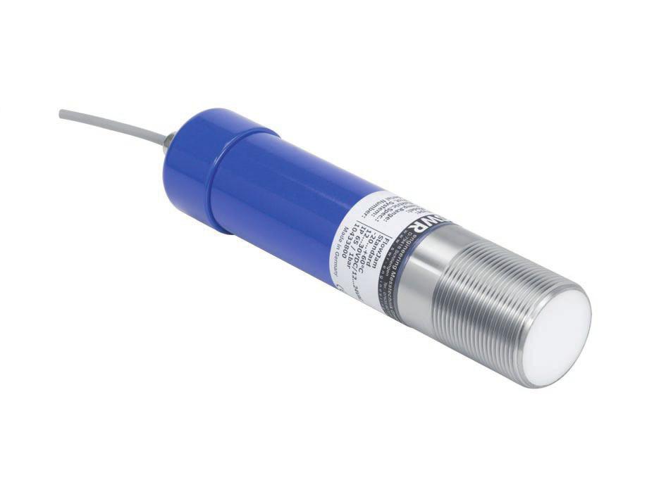
3 1. Function The radar flow detector FlowJam indicates the flow of bulk materials which move through the detection range (fig. 1) at a minimal required speed of 0.1 m/s. The detection is executed by evaluating the Doppler s effect, thus independent of the flow direction. The material flow, which can be in metallic or nonmetallic tubes, wells, free fall distances and discharge points, is indicated by a relay. The sensor distinguishes between two conditions: material flow material jam or standstill. FlowJam can be adapted to extreme process conditions like high process temperature by a separating flange equipped with a window especially for microwaves. Fig. 1: Detection range ø 52 G 1 1/2" Fig. 2: Dimensioned drawing 3
4 2. Safety The sensor FlowJam was designed, built and tested to be safe and was shipped in safe condition. Nevertheless persons or objects may be endangered by components of the system if these are operated in an inexpert manner. Therefore the operational instructions must be read completely and the safety notes must be followed. In case of inexpert or irregular use, the manufacturer will refuse any liability or warranty. 2.1 Regular Use Only original spare parts and accessories of SWR engineering must be used. 2.2 Identification of Dangers Possible dangers when using the sensor are marked in the operating instructions: 2.3 Operational Safety The sensor must be installed by trained and authorised personnel only. Switch off the supply voltage for all maintenance, cleaning or inspection works on the tubes or on components of the FlowJam. Before hot work the sensor must be removed from the installation place. The components and electrical connections must be checked for damages regularly. If a damage is found, it is to be repaired before further operation of the instrument. 2.4 Technical Progress The manufacturer reserves the right to adapt technical data to the technical progress without particular advance notice. If you have any questions, SWR engineering will be pleased to inform you on possible changes and extensions of the operating instructions. 4
5 3. Mounting and Installation 3.1 Basic remarks FlowJam has to be mounted at an angle between 45 and 90 to the flow direction of the bulk material. Be careful to mount the sensor in an vibration-free area and that there are no moving parts within the detection range, because they might be detected as a material flow. Moving parts within the area of detection have to be screened. 3.2 Installation of the sensor in general The installation of the sensor depends on the conditions of the site. For example, the sensor can be screwed directly into an existing thread type G 1 1/2 (fig. 3) fixed by a flange (fig. 4) mounted with the help of a pipe clamp (fig. 5) Before installation, make sure that neither the medium temperature nor the pressure within the piping or the container require additional measures like e.g. the mounting of a separating flange pervious for microwaves (fig. 6). When used non-conductive dielectric tubes, detection is carried from the outside of the tube. It is not necessary to make a separate hole into the tube. Fig. 3: Thread mounting Fig. 4: Flange mounting A B Fig. 5: Mounting with pipe clamp Fig. 6: Mounting with separating flange 5
6 3.3 Installation of the sensor on conveyor belts If possible, the installation on conveyor belts is to be executed in the area of the discharge point. If FlowJam is installed directly above a conveyor belt or if the bulk material to be detected does not show much profile, the sensor should be mounted at an angle of approx (fig. 7). Based on the formular for the Doppler frequency, the following relations can be pointed out: Df = 2 (V* cos α/c) fo (Fig. 8) V = resulting speed Df = frequency shift fo = transmitter frequency a = angle of the sensor to flow direction of the bulk material Angle approx. 90 : mainly the change of the surface profile is measured. Angle approx. 0 : mainly the material speed is measured. Fig. 7: Installation above conveyor belt Fig. 8: Determination of sensor s angle 6
7 4. Electrical Connection NO COM NC Signal strength (red) Material flow (green) Switching between working current / closed Coarse adjustment of sensitivity S1 S2 Threshold level P1 P2 Delay time Fig. 9: Terminal and operational controls NC COM NO ~ + ~ Power supply Relay V 110 V AC / 60 W 1 A Fig. 10: Wiring diagram for sensor For connection a 5-wired cable 5 x 0,25 mm 2 should be used. 7
8 5. Commissioning All operational controls required for the calibration are shown in fig. 11. Control elements: LED 1: Signal strength (red) LED 2: Material flow (green) S1: Switching between working current / closed current NO COM NC Signal strength (red) Material flow (green) Switching between working current / closed Coarse adjustment of sensitivity S2: P1: P2: Coarse adjustment of sensitivity Threshold level Delay time Threshold level P1 P2 S1 S2 Delay time Fig. 11: Position of operating controls Switch S1 The position of switch S1 determines, whether the relay is attracted up or released at material flow. Position 2 (off) causes alarm in case of material flow: material flow no material flow - relay is attracted - contacts closed - relay is released - contacts closed Position 1 (on) causes alarm when there is no material flow: material flow no material flow - relay is released - contacts closed - relay is attracted - contacts closed LED 1 LED 1 (red) indicates the signal strength by its brightness: that means, no lightning if no reception signal (no material flow, no vibrations, etc.), weak lightning if low and strong lightning if intense reception signal. LED 2 LED 2 (green) lights always up, if material flow is detected; this display is independent from the position of switch S1. 8
9 Adjustment of sensitivity Therefor use switch S2, potentiometer P1 and potentiometer P2. The default status for the control elements is as follows (setting for initial commissioning): P1 (fine adjustment of sensitivity): fully counter-clockwise, min. sensitivity S2 (coarse adjustment of sensitivity): switch at (on), less sensitivity P2 (delay time): fully counter-clockwise, minimal delay of 1 s Now start your system in order to guarantee material flow. In consequence LED 1 must light-up. If LED 1 doesn t light-up, switch S2 has to be set on (off). If there is still no indication, either the sensor has to be aligned differently, and/or you probably need a sensor with high sensitivity. Now choose the position of switch S1 accordingly, to define whether the relay has to be turned (on) or (off) at flow condition. Increase the sensitivity until LED 2 indicates and the relay switches (off) or (on). If you interrupt the material flow, both LED have to go out, whereas LED 2 indication stops not before end of delay time. Finally adjust the delay time according to your requirements with potentiometer P2 in the range of s. 6. Troubleshooting If LED 1 does not light up even with the highest possible sensitivity, the following points must be checked: properties of the material flow (see e.g. fig. 7) positioning of the installation distance between the sensor and the material flow If LED 1 lights up without an existing material flow and with minimal sensitivity adjusted on S2 and P1, it is very likely that the sensor detects the motion of any moving on vibrating part. Attention: Does LED 1 indicate continuously, then either there is no connection between sensor and transmitter, or the sensor is broken! 7. Notice Avoidance of reflection by vibration or moving line parts Setting of the sensitivity by potentiometer P1 up to the switching threshold (LED 2 lightening) 9
10 8. Declaration of conformity Conforms to the following Product Specifications: Number: Text: 89/336/EEC Electromagnetic Compatibility The product herewith complies to requirements of the EMC directive 89/336/EEC: Reference No. Date Reference No. Date DIN EN DIN EN DIN EN DIN EN DIN EN DIN EN DIN EN DIN EN Technical Data Housing Stainless steel Protective system IP 65 Process temperature C C (with process-adapter) Max C (with ceramic-flange) Ambient temperature C Dimensions see Fig. 2 Max. working pressure Detection range Min. required material speed for detection Power supply Power consumption Current consumption Relay max. Voltage Current Capacity Fall-delay time Measuring frequency Transmitting power Approvals Weight 1 bar m (dependent on application) 0.1 m/s V DC / AC approx. 1.7 VA 70 ma at 24 V 250 V AC 1 A AC 60 W 1 s s (continously adjustable) K-Band GHz / ± 100 MHz max. 5 mw FTZ and PTT 1.0 kg SWR engineering Messtechnik GmbH Gutedelstraße Schliengen (Germany) Fon Fax (All rights reserved.) EN 18/01/
FlowJam S Ex. Bulk Flow Detection. Operating Instructions. SWR engineering Messtechnik GmbH
 EN FlowJam S Ex Operating Instructions Bulk Flow Detection SWR engineering Messtechnik GmbH CONTENTS Page 1. Function.......................................................................... 3 2. Safety..............................................................................
M-Sens 2. Online moisture measurement for solids. Operating Instructions. SWR engineering Messtechnik GmbH PART OF THE ENVEA GROUP
 EN M-Sens 2 Operating Instructions Online moisture measurement for solids SWR engineering Messtechnik GmbH PART OF THE ENVEA GROUP CONTENTS Page 1. System overview.............................................
M-Sens 2. Online-Moisture Meter for Solids. Operating Instructions. SWR engineering Messtechnik GmbH
 EN M-Sens 2 Operating Instructions Online-Moisture Meter for Solids SWR engineering Messtechnik GmbH CONTENTS Page 1. System Overview......................................................................
SWARCO TRAFFIC SYSTEMS GMBH. TDD1-MW Traffic Detector User Manual TDD1-MW_BE_00
 TDD1-MW Traffic Detector User Manual TDD1-MW_BE_00 CONTENTS 1 Introduction... 3 1.1 About this manual... 3 1.2 Usage according to regulations... 3 1.3 Label... 4 1.4 Symbols... 4 1.5 Safety instructions...
Dusty / Dusty Ex Low-Cost Broken Bag Detection
 EN Operating Instructions Superior Dusty / Dusty Ex Low-Cost Broken Bag Detection SWR engineering Messtechnik GmbH PART OF THE ENVIRONNEMENT S.A GROUP CONTENTS Page 1. Introduction..............................................................
M-Sens 2 Application overview. FlowJam application overview. Online moisture measurement for solids. For measuring capillary and surface humidity
 Online moisture measurement for solids "Supplying intelligent measuring systems for industry since 1994" Development + Production + Sales + Commissioning + After-Sales FlowJam application overview For
MICROSENSE FLOW SWITCH
 MICROWAVE FLOW SWITCH Elec Iss. 03 MICROSENSE FLOW SWITCH FOR SOLIDS, GRANULES AND POWDERS MICROSENSE - PRINCIPLE OF OPERATION The Microsense microwave switch provides an effective way of detecting the
Dimensions. Electrical connection. Model Number. Features. Indicators/operating means. Product information RAVE-D. Radar sensor
 Dimensions 139.6 103 99.6 46 130.7 Electrical connection Model Number Radar sensor Features Degree of protection IP67 Differentiated detection of people and vehicles, each with one output relay Cross-traffic
UV Flame Supervision System
 7 783 UV Flame Supervision System DETACTOGYR LFE50 Series 02 ISO 9001 The LFE50 is a self-checking UV flame supervision system designed for use with continuously operating burners or for burners running
DHR3. Accessories. NOTE: Set up for this sensor should be performed by an AAADM-certified installer. INSTALLATION INSTRUCTIONS
 NOTE: Set up for this sensor should be performed by an AAADM-certified installer. Section 1 General Description The DHR3 is a combination microwave/infrared sensor providing both motion detection and presence
TABLE OF CONTENTS Flow Detect 1000 Specifications 3 Description 4 Principle of Operation 4 Detection Through Walls 4 Sensing Beam Shape 4 Installation
 DETECT 1000 DOPPLER DETECTION INSTALLATION AND OPERATING INSTRUCTIONS READ THOROUGHLY BEFORE INSTALLING EQUIPMENT TABLE OF CONTENTS Flow Detect 1000 Specifications 3 Description 4 Principle of Operation
Dimensions. Electrical connection. Model Number. Features. Indicators/operating means. Product information RAVE-D-NA. Radar sensor
 Dimensions 139.6 103 99.6 46 130.7 Electrical connection Model Number Radar sensor Features Degree of protection IP67 Differentiated detection of people and vehicles, each with one output relay Cross-traffic
Dimensions. Model Number 123. Electrical connection. Features. Indicators/operating means. Product information RMS-G-RC-NA.
 Dimensions ø.7 9.5 6.5 8.5 ø.7 65 57 Window for LED display Model Number Radar sensor Features Industrial gate opener with the ability to differentiate between people and vehicles Extra-wide detection
Microwave Doppler Flow Switch. Installation & Operation Manual
 Microwave Doppler Flow Switch Type Microsense DFS Installation & Operation Manual Hycontrol Limited, Larchwood House, Orchard Street,, Redditch, Worcestershire, B98 7DP, England Tel: + 00 44 (0)1527 406800
Wind Alarm Instrument
 THE WORLD OF WEATHER DATA - THE WORLD OF WEATHER DATA - THE WORLD OF WEATHER DATA Instruction for Use 020952/02/99 Wind Alarm Instrument 4 4.3242.02.000 ADOLF THIES GmbH & Co. KG Hauptstraße 76 37083 Göttingen
Dimensions. Model Number. Electrical connection. Features. Product information. Indicators/operating means RMS-G-RC. Radar sensor
 Dimensions ø.7 9.5 6.5 8.5 ø.7 65 57 Window for LED display Model Number Radar sensor Features Industrial gate opener with the ability to differentiate between people and vehicles Extra-wide detection
ProSens Dust Measurement
 EN Operating Instructions ProSens Dust Measurement SWR engineering Messtechnik GmbH CONTENTS Page 1. Introduction.......................................................................... 3 1.1 Safety............................................................................
SPACEMOTION SERIES SMM 01
 SPACEMOTION SERIES SMM 01 Description K-Band motion and direction detection Max sensing range: 3 metres Adjustable sensing field range Adjustable slow speed zone Selectable background suppression Selectable
Low-Cost, Non-Invasive, Microwave-Based Bulk Solids Flow Detector
 Low-Cost, Non-Invasive, Microwave-Based Bulk Solids Flow Detector Granuflow Principle Sensor Features The Granuflow, a non-contact flow sensor, is ideal for monitoring solids flow in pipelines, ducts,
LFE50. UV Flame Safeguard. Siemens Building Technologies HVAC Products DETACTOGYR. Series 02
 7 783 ISO 9001 DETACTOGYR Flame Safeguard Series 02 The... together with the QRA50M / QRA51M form a self-checking flame supervision system (DETACTOGYR ) designed for use with continuously operating oil
WIRELESS OUTDOOR DUAL TECHNOLOGY MOTION DETECTOR AOD-200
 aod-200_en 05/16 WIRELESS OUTDOOR DUAL TECHNOLOGY MOTION DETECTOR AOD-200 SATEL sp. z o.o. ul. Budowlanych 66 80-298 Gdańsk POLAND tel. +48 58 320 94 00 www.satel.eu Firmware version 1.0 WARNING The device
for relative humidity and temperature
 1 861 1861P01 Duct sensor for relative humidity and temperature QFM65 Operating voltage AC 24 V Signal output DC 0...10 V for relative humidity and temperature Measurement accuracy ±3 % r. h. within the
Reflective Optical Beam Smoke Detector User Guide
 Reflective Optical Beam Smoke Detector User Guide 1. Installation IMPORTANT NOTE: The infrared beam path MUST be kept clear of obstructions at all times! Failure to comply may result in the system initiating
Photobeam 5000 ISC-FPB1-W60QS, ISC-FPB1-W120QS, ISC-FPB1-W200QS. en Installation and Operation Guide
 Photobeam 5000 ISC-FPB-W60QS, ISC-FPB-W20QS, ISC-FPB-W200QS en Installation and Operation Guide Photobeam 5000 Table of Contents en 3 Table of contents Introduction 4. About documentation 4.2 Bosch Security
active infrared 875 nm < 250 mw/m² motion & presence 157 in x 157 in (emitting spots**) 2 in/s to activate detection 250 ms 15-45
 2 in/s to activate detection 250 ms 15-45") Please keep for further use Designed for color printing Other use of the device is outside the permitted purpose and can not be guaranteed by the manufacturer. The manufacturer cannot be held responsible
Please keep for further use Designed for color printing Other use of the device is outside the permitted purpose and can not be guaranteed by the manufacturer. The manufacturer cannot be held responsible
Instruction manual. Digital Radar Motion Detector with Infrared Remote Control MWD BF. FEIG ELECTRONIC GmbH Lange Straße Weilburg/Lahn
 Instruction manual Digital Radar Motion Detector with Infrared Remote Control MWD BF FEIG ELECTRIC GmbH Lange Straße 4 35781 Weilburg/Lahn 22.08.02 MWD BF Instruction manual General Copyright 2002 by FEIG
Safety instructions VEGAMIP MPR61(*).G*/DK****R/T*** VEGAMIP MPT61(*).G*/DK****T*** VEGAMIP MPR62(*).G******R/T*** IECEx BVS Ex t IIIC T..
.G*/DK****R/T*** VEGAMIP MPT61(*).G*/DK****T*** VEGAMIP MPR62(*).G******R/T*** IECEx BVS Ex t IIIC T..") Safety instructions VEGAMIP MPR61(*).G*/DK****R/T*** VEGAMIP MPT61(*).G*/DK****T*** VEGAMIP MPR62(*).G******R/T*** IECEx BVS 09.0054 Ex t IIIC T.. Da, Da/Db, Da/Dc, Db IP 66 0044 41673 Contents 1 Area
Safety instructions VEGAMIP MPR61(*).G*/DK****R/T*** VEGAMIP MPT61(*).G*/DK****T*** VEGAMIP MPR62(*).G******R/T*** IECEx BVS 09.0054 Ex t IIIC T.. Da, Da/Db, Da/Dc, Db IP 66 0044 41673 Contents 1 Area
Retroreflective sensor with polarization filter
 Dimensions 45 49 Receiver 27 74 Emitter 92 56 23 6 x 9 slots S 23 25 32 Internal thread (1/2-14 NP) External thread (M30 x 1.5) ø 6 mm Cable 10 Model Number Retroreflective sensor with fixed cable Features
Procedure for the Approval of New Fire Detection and Alarm Technologies
 VdS Guidelines for Automatic Fire Detection and Fire Alarm Systems VdS 3469en Procedure for the Approval of New Fire Detection and Alarm Technologies VdS 3469en : 2016-01 (01) Publisher and publishing
LFE50. UV Flame Safeguard. Building Technologies Division DETACTOGYR
 7 783 DETACTOGYR Flame Safeguard The... together with the QRA50M / QRA51M form a self-checking flame supervision system (DETACTOGYR ) designed for use with continuously operating oil or gas burners or
Universal fault annunciator for panel mounting
 Universal fault annunciator for panel mounting Communication over Ethernet USM - Universal-fault annunciator for panel mounting Low depth housing for panel mounting Versions with 8, 16, 32 or 48 inputs
OPTISENS TUR 2000 Technical Datasheet
 OPTISENS TUR 2000 Technical Datasheet Sensor for turbidity measurement in water and wastewater Rugged design for harsh applications Integrated transmitter with direct 4...20 ma output Near infrared light
HANDBUCH / MANUAL / MANUEL / MANUALE TopScan-S
 FACTORY AUTOMATION HANDBUCH / MANUAL / MANUEL / MANUALE TopScan-S Certification Type Tested Inhalt / Content / Sommaire / Indice Deutsch......................................................... 3 English.........................................................
Laser Distance Sensor Type M Analog-Output
 Laser Distance Sensor Type M Analog-Output Operating Manual Version 2.3, May 2009 ELAG Elektronik AG l Stegackerstrasse 14 l CH-8409 Winterthur Contents 1. Safety 1.1 Laser safety 1.2 Electrical safety
for relative humidity and temperature
 1 860 1860P01 Duct sensor for relative humidity and temperature QFM651 Operating voltage AC 24 V Signal output DC 010 V for relative humidity Signal output L&S Ni 1000 (passive) for temperature Measurement
TER Active Room Temperature Sensor (Controller),
,") Product sheet SN1.415 Type TER TER Active Room Temperature Sensors (Controllers) The TER active sensors are designed to detect temperature in the room spaces. The TER sensors have linear 0..10V signals
Product sheet SN1.415 Type TER TER Active Room Temperature Sensors (Controllers) The TER active sensors are designed to detect temperature in the room spaces. The TER sensors have linear 0..10V signals
MWS3 Ceiling Mount Microwave Occupancy Detector
 MWS3_0916/ISSUE1 MWS3 Ceiling Mount Microwave Occupancy Detector Description: the MW3SA offers a unique presence/absence detection capability by using an adjustable head. This incorporates an innovative
COMPACT FLAME CONTROLLER CFC 1000
 COMPACT FLAME CONTROLLER CFC 1000 TECHNICAL DESCRIPTION EDITION: TB CFC1000- REV.6 2012-03-07 Important: Please note, that all mounting and wiring as well as all changing or adjustment at the flame monitoring
FSTR- Series Microwave Motion Sensor (MSSD) Dimming Function/Detachable Version for LED Tri-proof Light & LED Batten. Introduction
 Dimming Function/Detachable Version for LED Tri-proof Light & LED Batten. Introduction") Dimming Function/Detachable Version for LED Tri-proof Light & LED Batten Introduction Unique split design makes it suitable to fix within lamps which have limited space. Automatic dimming when used in
Dimming Function/Detachable Version for LED Tri-proof Light & LED Batten Introduction Unique split design makes it suitable to fix within lamps which have limited space. Automatic dimming when used in
Emergency power automatics MS-2. High resistance to shock, vibrations and transients. All output are 2A relay contacts
 Emergency power automatics Type EPOMATIC MS-2, EC-2 4921240002D MS-2 EC-2 DEIF A/S All necessary functions: - mains supervision - start/supervision/stop of diesel engine - control of circuit breakers and
COMPACT FLAME CONTROLLER CFC 200 (Formerly 8.XX)
") COMPACT FLAME CONTROLLER CFC 200 (Formerly 8.XX) TECHNICAL DESCRIPTION EDITION: TB CFC200-REV3-2015-04-07 IMPORTANT: Please note, that all mounting and wiring as well as all changing or adjustment at the
COMPACT FLAME CONTROLLER CFC 200 (Formerly 8.XX) TECHNICAL DESCRIPTION EDITION: TB CFC200-REV3-2015-04-07 IMPORTANT: Please note, that all mounting and wiring as well as all changing or adjustment at the
Wind Alarm Instrument x.x0x
 THE WORLD OF WEATHER DATA - THE WORLD OF WEATHER DATA - THE WORLD OF WEATHER DATA Instruction for Use 000/0/0 Wind Alarm Instrument..0x.x0x ADOLF THIES GmbH & Co. KG Hauptstraße 0 Göttingen Germany Box
INSTRUCTION MANUAL T119 1MN0110 REV. 0. operates with ISO9001 certified quality system
 INSTRUCTION MANUAL 1MN0110 REV. 0 operates with ISO9001 certified quality system TECSYSTEM S.r.l. 20094 Corsico (MI) Tel.: +39-024581861 Fax: +39-0248600783 http://www.tecsystem.it R. 1.1 25/08/16 ENGLISH
Ex SOLENOID / ALARM DRIVER. PRepower 5203B. Table of contents. Applications Safety instructions Technical characteristics...
 14 Ex SOLENOID / ALARM DRIVER PRepower 5203B Table of contents Warnings... 16 Safety instructions... 17 Declaration of Conformity... 19 How to dismantle SYSTEM 5000... 20 Application... 21 Technical characteristics...
1 Safety instructions. 2 Device components. Presence detector. Operating instructions
 Presence detector Standard Art. No. 3361 WW Presence detector Standard Art. No. 3361 AL Presende detector Universal Art. No. 3361-1 WW Presende detector Universal Art. No. 3361-1 AL Operating instructions
CU 300 GRUNDFOS INSTRUCTIONS. Installation and operating instructions
 GRUNDFOS STRUCTIONS CU 300 Installation and operating instructions No contact Overvoltage Undervoltage Dry running Speed reduction Overtemperature Overload Sensor alarm Declaration of Conformity We Grundfos
COMPACT FLAME CONTROLLER CFC 2000
 COMPACT FLAME CONTROLLER CFC 2000 TECHNICAL DESCRIPTION EDITION: TB_CFC2000_EN_REV09_20150408 Important: Please note, that all mounting and wiring as well as all changing or adjustment at the flame monitoring
Movement-based energy control
 04 Movement-based energy control 94 International catalogue 2015 4.1 Microwave-based movement sensors 4.2 PIR-based movement sensors 4.2.1 Ceiling-mount 4.2.2 Wall-mount 4.3 Twilight switches 4.4 LED lights
English. Series. Installation and Use Manual
 English Series FOSTER Installation and Use Manual FOSTER Rev.13 03/2015 MITECH srl reserves the right to change the information in this document without warning. Index Anti-intrusion barrier 3 Main components
PRODUCT INFORMATION. Uses tough, high quality PC diffuser, resistant to fracture and to ultraviolet light to limit discolouring.
 Ø297mm Packing list in Ceiling Mount Lamp LEDS 96PCS Φ6 Wall plug 3x30 Screw Φ3 Sealing ring 4x12 Y type Stainless Screw Quantity 1X 4X 4X 3X 3X PRODUCT INFORMATION 98.5mm Ideal for energy saving this
FACTORY AUTOMATION HANDBUCH / MANUAL / MANUAL / MANUALE
 FACTORY AUTOMATION HANDBUCH / MANUAL / MANUAL / MANUALE Radar-Bewegungsmelder Radar Motion Sensor Avisador de movimientos radar Rilevatori di movimento radar RMS-D, RMS-D-RC, RMS-D BROAD RMS-D-NA, RMS-D-RC-NA
For the user / for the installer. Instructions for Use and Installation. time SWITCH hour time clock
 For the user / for the installer Instructions for Use and Installation time SWITCH 130 24 hour time clock GB GB Contents GB 24 hour time clock Operating instructions page 4-9 Installation instructions
XUBLAPCNL2 photo-electric sensor - XUB - thru beam - laser - Sn 100m VDC - cable 2m
 Characteristics photo-electric sensor - XUB - thru beam - laser - Sn 100m - 12..24VDC - cable 2m Buy online Complementary Enclosure material Lens material Blind zone Output type Status LED [Us] rated supply
ACTIV8 ONE OFF. 1 Tips USER S GUIDE COMBINED RADAR OPENING AND ACTIVE INFRARED SAFETY SENSOR. 1 Description. 2 Symbols.
 ACTIV8 ONE OFF USER S GUIDE COMBINED RADAR OPENING AND ACTIVE INFRARED SAFETY SENSOR 1 Description Cover 2 nd Radar Antenna Radar motion sensor Push-Buttons IR-Presence sensor Radar Antenna clip IR-Prism
Instruction Manual. Alarm Unit For Low Gas Level # Read manual before use! Observe all safety information! Keep manual for future use!
 Mess-, Regel- und Überwachungsgeräte für Haustechnik, Industrie und Umweltschutz Lindenstraße 20 74363 Güglingen Telefon +49 7135-102-0 Service +49 7135-102-211 Telefax +49 7135-102-147 info@afriso.de
Daylight harvest function to regulate light output for maintaining required lux level
 TM Ambient daylight threshold oop in oop out HF Aisle Sensor Trilevel Control with Daylight Harvest and Remote Control Applications Occupancy detector with trilevel dimming control suitable for below applications:
IP65 High Bay Dual Sense Sensor
 IP65 High Bay Dual Sense Sensor TM and, 1-10V Dimming with Remote Control Technical Data Input Characteristics Sensor Data Model No. Model No. Mains voltage 220-240VAC 50/60Hz Sensor principle High Frequency
Photobeam 5000 ISC-FPB1-W60QF, ISC-FPB1-W120QF, ISC-FPB1-W200QF. en Installation and Operation Guide
 Photobeam 5000 ISC-FPB-W60QF, ISC-FPB-W0QF, ISC-FPB-W00QF en Installation and Operation Guide Photobeam 5000 Table of Contents en 3 Table of contents Introduction 4. About documentation 4. Bosch Security
LC2200 Level Controller Installation and Maintenance Instructions
 4025250/9 IM-P402-77 AB Issue 9 LC2200 Level Controller Installation and Maintenance Instructions LC2200 ALARM TEST >50% >100%
Operating manual GTL 369 GTL 369M GTL 389 GTL 389M. Temperature probe. Please keep the manual for future use.
 Operating manual Temperature probe GTL 369 GTL 369M GTL 389 GTL 389M Please keep the manual for future use. L02.0.3X.6C-01 GREISINGER electronic GmbH Hans-Sachs-Str. 26 93128 Regenstauf Germany Fon +49(0)9402-9383-0
Residual current monitor RCM470LY/RCM475LY. for TN and TT systems (AC and pulsating DC currents)
") Residual current monitor RCM470LY/RCM475LY for TN and TT systems (AC and pulsating DC currents) TDB401003en/03.2010 Residual current monitor RCM470LY Residual current monitor for TN and TT systems (AC
Residual current monitor RCM470LY/RCM475LY for TN and TT systems (AC and pulsating DC currents) TDB401003en/03.2010 Residual current monitor RCM470LY Residual current monitor for TN and TT systems (AC
GMA4100-DP. Control Panel. Operation Manual. Worldwide Supplier of Gas Detection Solutions
 Worldwide upplier of Gas Detection olutions GfG Instrumentation 1194 Oak Valley Drive, uite 20 Ann Arbor, MI 48108 800-959-0329 tel 734-769-1888 fax email: info@gfg-inc.com GMA4100-DP Control Panel Operation
Instruction Manual. Electronic gas and smoke detector GRM
 Mess-, Regel- und Überwachungsgeräte für Haustechnik, Industrie und Umweltschutz Lindenstraße 20 DE-74363 Güglingen Telefon +49(0)7135-102-0 Service +49(0)7135-102-211 Telefax +49(0)7135-102-147 E-Mail
/ / 2018
 Original operating instructions Photoelectric safety sensors (safety light curtain / safety light grid) with IP69K protective tube Protected area width (range) 0...10 m OY4xxS UK 704859 / 05 02 / 2018
PHOTOELECTRIC AMPLIFIER SERIES
 PHOTOELECTRIC AMPLIFIER SERIES Telco s photoelectric amplifier series performs as good today as it did when it first appeared almost 25 years ago. But while the simple design of this iconic product has
Original operating instructions Photoelectric safety sensors (safety light curtain / safety light grid) Protected area width (range) 0...
 Protected area width (range) 0...") Original operating instructions Photoelectric safety sensors (safety light curtain / safety light grid) Protected area width (range) 0...12 m OY UK 704555 / 05 02 / 2018 Contents 1 Preliminary note...4
Original operating instructions Photoelectric safety sensors (safety light curtain / safety light grid) Protected area width (range) 0...12 m OY UK 704555 / 05 02 / 2018 Contents 1 Preliminary note...4
FLAME AMPLIFIER MODULE 3001
 SYSTEM 3000 / 4000 FLAME AMPLIFIER MODULE 3001 TECHNICAL DESCRIPTION EDITION TB_3001_EN_REV03 BFI Automation Mindermann GmbH, Eggerscheidter Str. 57, D-40883 Ratingen Phone +49 (0) 2102 96 82 0, Fax +49
Operating instructions Safety-monitoring module SRB 302X3. 1. About this document. Content
 8 Appendix 8.1 Wiring examples...4 8.2 Start configuration...4 8.3 Sensor configuration...4 8.4 Actuator configuration...5 Operating instructions.............pages 1 to 6 Original 9 EU Declaration of conformity
IP65 High Bay Dual Sense Sensor
 IP65 High Bay Dual Sense Sensor TM and, Daylight Harvest with Remote Control Technical Data Input Characteristics Sensor Data Model No. Model No. Mains voltage 220-240VAC 50/60Hz Sensor principle High
Vibracon LVL-A* Level limit switch for liquids, compact design
 Technical Information TI 364O/98/en/.07 8905 /07 0 Vibracon LVL-A* Level limit switch for liquids, compact design Application The Vibracon LVL-A* is a level limit switch for all kinds of fluids and is
Ultrasonic Level Measurement nivopuls FDU 10 S
 Technical Information TI 275F/00/en Ultrasonic Level Measurement nivopuls FDU 10 S Level limit switch for liquids with separate electronics unit Non-contact from outside Suitable for use in explosion hazardous
English. Italiano. Português. Françias. Español
 DT AM Grade 3 Español Françias Português Italiano English High Ceiling Mount Detector Installation Guide English DT AM Grade 3 High Ceiling Mount Detector Installation Guide General Description The Industrial
Operator's Manual. LIGHTNING 2 Laser Detector
 Operator's Manual LIGHTNING 2 Laser Detector Thank you for purchasing an Apache Technologies, Inc. product. Your LIGHTNING 2 Laser Detector is a premium quality tool that has been designed and manufactured
UV - flame detector dual fuel burners for intermittent burner operations
 KLC 11 1(formerly known as KLC 1001) Technical information UV - flame detector KLC 11 for oil -, gas- and dual fuel burners for intermittent burner operations 0085 Description The KLC 11 is a compact UV
Original operating instructions Safety switch with guard locking AC901S AC902S
 Original operating instructions Safety switch with guard locking AC901S AC902S 7390914/03 01/2017 Contents 1 Preliminary note...4 1.1 Explanation of symbols...4 2 Safety instructions...4 3 Items supplied...5
Tri-level Control HF Sensor
 Tri-level Control HF Sensor Standard Version Applications Occupancy detector with tri-level control suitable for indoor use. Suitable for building into the fixture: Office / Commercial Lighting Use for
System 2000 System 2000 presence detector Comfort top unit. 1 Safety instructions. 2 Device components
 pure white Order-No. : 0317 02 colour aluminium Order-No. : 0317 04 Operating instructions 1 Safety instructions Electrical equipment may only be installed and fitted by electrically skilled persons. Failure
DD205RF/TX Detector Installation Sheet
 GE Security DD205RF/ Detector Installation Sheet EN DE EL ES FR IT NL PT RU TR 2009 GE Security, Inc. 1 of 28 P/N 1060783 REV 1.00 ISS 26FEB09 2 of 28 P/N 1060783 REV 1.00 ISS 26FEB09 EN: Installation
REA 105 Arc Protection Module. Operator s Manual
 REA 105 1MRS 751005-MUM Issued: 20.04.1998 Version: B2/26.5.2000 Checked: Approved: REA 105 We reserve the right to change data without prior notice. Contents: 1. General...4 1.1. Features...4 2. Safety...5
DEIF A/S. Technical Manual. Type EC-2 Engine Control Unit D. Technical Manual
 Technical Manual Type EC-2 Engine Control Unit 4189340232D DEIF A/S Technical Manual DEIF A/S Tel.: (+45) 9614 9614 Frisenborgvej 33, DK-7800 Skive Fax: (+45) 9614 9615 Denmark E-mail: deif@deif.com Contents
Motorised Infrared Optical Beam Smoke Detector. User Guide
 Motorised Infrared Optical Beam Smoke Detector User Guide EN 1. General Information 50cm 50cm 8-100m Ensure clear line of sight from Detector to Reflector Mount on solid surfaces (structural wall or girder)
WM3000 WIRELESS MODULES
 WM3000 WIRELESS MODULES $$:05 $$:07 INSTALLATION INSTRUCTIONS Table of Contents Installation... 3 Mounting Instructions & Connections... 3 Setting the Dip Switches... 4 Setting the Recognition Time...
Snifter ATEX22 VERSION. User Manual. Distributor
 Snifter ATEX22 VERSION User Manual Distributor Version 1.4 09/09/2009 Table of Contents 1. INTRODUCTION... 3 1.1. Safety... 3 1.2. Product overview... 4 1.3. How does it work?... 4 2. INSTALLATION... 5
USER GUIDE. DRENA 2 - User Manual ELECTRICAL PANEL FOR 2 MOTORS - WASTE WATER -
 USER GUIDE DRENA 2 - User Manual ELECTRICAL PANEL FOR 2 MOTORS - WASTE WATER - II CONTENTS 1. SYMBOLS AND WARNINGS... 5 2. GENERAL INFORMATION... 6 3. WARNINGS... 7 4. GENERAL DESCRIPTION... 8 5. INSTALLATION...
MPAD-C 12-24V. Ceiling microwave presence/absence detector 12-24V AC/DC. Product Guide. Overview. Features
 Product Guide MPAD-C 12-24V Ceiling microwave presence/absence detector 12-24V AC/DC Overview The MPAD-C 12-24V Microwave presence detector provides automatic control of low voltage loads including lighting
Operating instructions Safety-monitoring module SRB 302X3. 1 About this document
 1 About this document Operating instructions... pages 1 to 6 Translation of the original operating instructions 1.1 Function This operating instructions manual provides all the information you need for
Table of Contents. 1. Mounting Tips... 2
 Table of Contents 1. Mounting Tips............................................. 2 1.1. Connections and DIP switch settings................................... 3 1.2. Mounting the Fireray 50/100RV........................................
Technical data lumina MS4
 1. Product description Technical data The is a combination of occupancy sensor, two light sensors and infrared remote control receiver. An external temperature sensor can be connected. The sensitive 4-element-PIR
LC3000 Level Controller Installation and Maintenance Instructions
 4025550/12 IM-P402-36 AB Issue 12 LC3000 Level Controller Installation and Maintenance Instructions 1. General safety information LC3000 NORM ALARM TEST 2. General product information 3. Installation 4.
QAF63.2 QAF63.6. Frost sensors for use on the air side. Building Technologies HVAC Products
 1 821 1821P01 Frost sensors for use on the air side Active capillary tube sensor for measuring the lowest temperature within a range of 0 15 C Operating voltage AC 24 V Signal output DC 0...10 V Use On
enproteko.com Specifications Ratings Item voltage to 24 VAC 5/6 Hz 24 VAC 5/6 Hz or 24 VDC Allowable voltage Characteristics 85% to 11% of power suppl
 enproteko.com Temperature Monitoring Relay K8AB-TH Compact and Slim Relay Ideal for Temperature Alarms and Monitoring Excessive increases can be prevented and abnormal s can be monitored. Temperature monitoring
Operating Manual UV Monitor UVT 18
 Operating Manual UV Monitor UVT 18 Software Version 1.2 stand: 21/11/2016 UV - Monitor UVT 18 Intended use The signal monitor UVT 18 was developed to control small- and medium-sized UV systems and is fully
Motorised Infrared Optical Beam Smoke Detector. User Guide
 Motorised Infrared Optical Beam Smoke Detector User Guide EN 1. General Information 50cm 50cm 8-100m Ensure clear line of sight from Detector to Reflector Mount on solid surfaces (structural wall or girder)
Temperature Sensor TRG Original Installation Instructions English
 Temperature Sensor TRG 5-6.. EN English Original Installation Instructions 818597-05 1 Contents Important notes Page Usage for the intended purpose...4 Function...4 Safety note...4 Directives and standards
DH400. Accessories. NOTE: Set up for this sensor should be performed by an AAADM-certified installer.
 NOTE: Set up for this sensor should be performed by an AAADM-certified installer. Section 1 General Description The is a high mount microprocessor controlled active infrared presence detector for all types
NO (SPST-NO) 10 A Internal installations Particularly suited for wall mounting
 10 A Internal installations Particularly suited for wall mounting") Features PIR movement detector for internal or external installations - wall mounting Small size Adjustable ambient light intervention threshold Adjustable Light On Time Universal mounting position - permits
Features PIR movement detector for internal or external installations - wall mounting Small size Adjustable ambient light intervention threshold Adjustable Light On Time Universal mounting position - permits
Pipe Freeze Protection Control SCFP-CO-F130 Installation and Operation Manual
 MANUAL Pipe Freeze Protection Control SCFP-CO-F130 Installation and Operation Manual Model FPT 130 Single Point Freeze Protection Heat Trace Control Table of Contents SCFP-CO-F130 Overview... 3 Installation...
Dissolved Oxygen Measurement liquisys M COM 223 / 253
 Technical Information TI 199C/24/ae Dissolved Oxygen Measurement liquisys M COM 223 / 253 Oxygen Controller Benefits at a glance Liquisys M COM 223 Liquisys M COM 253 Due to the modularity of its design,
MODEL: 47LPQ. Digital Panel Meters 47 Series. [3] ALARM OUTPUT 0: None 1: N.O. relay contact, 4 points 2: SPDT relay contact, 2 points
![MODEL: 47LPQ. Digital Panel Meters 47 Series. [3] ALARM OUTPUT 0: None 1: N.O. relay contact, 4 points 2: SPDT relay contact, 2 points](/thumbs/90/103092504.jpg "MODEL: 47LPQ. Digital Panel Meters 47 Series. [3] ALARM OUTPUT 0: None 1: N.O. relay contact, 4 points 2: SPDT relay contact, 2 points") Digital Panel Meters 47 Series PULSE INPUT TOTALIZER (6-digit, LED display type) Functions & Features 6-digit digital panel meter 1/8 DIN size Process integration/totalization with scaling factor adjustment
Digital Panel Meters 47 Series PULSE INPUT TOTALIZER (6-digit, LED display type) Functions & Features 6-digit digital panel meter 1/8 DIN size Process integration/totalization with scaling factor adjustment
Annunciator Unit SACO 16 D1. Product Guide
 Issued: Aprill 1999 Status: Updated Version: C/20.03.2006 Data subject to change without notice Features Flexible, field-customizable 16-channel annunciator unit Alarm channels activated by normally open