Dusty / Dusty Ex Low-Cost Broken Bag Detection
|
|
|
- Shonda Horn
- 5 years ago
- Views:
Transcription


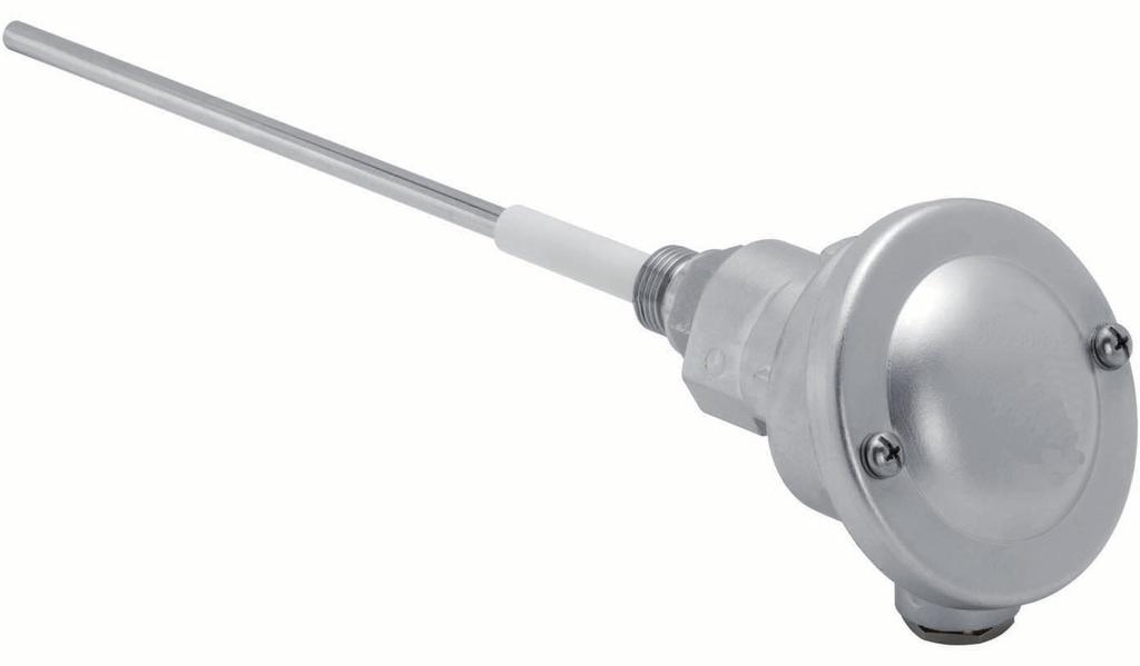
1 EN Operating Instructions Superior Dusty / Dusty Ex Low-Cost Broken Bag Detection SWR engineering Messtechnik GmbH PART OF THE ENVIRONNEMENT S.A GROUP
2 CONTENTS Page 1. Introduction Safety Product Overview How does it work Installation Selecting the Installation Location Installing the Sensor Electrical Connection Dusty as Stand Alone Dust Switch Dusty DIN Rail Converter Connecting Multiple Sensors using the C3-Box Dusty M12 plug DIN Rail Converter Use in Ex Hazardous Areas Dimensions Sensor DIN Rail Converter Dimensions C1-Box (opional) Dimensions C3-Box (opional) Operation Alert Level One Button Operation AutoSetup DIN Rail Converter Relay Output Configuration PC-Software Info Tab DRC Tab Sensor Tab Trend Tab DRC Multiple Sensors Register Sensors Leading Sensor Maintenance Troubleshooting Technical Data
3 1. Introduction 1.1 Safety Dusty requires 24 ±10 % V DC power supply. 24 ±10 % V DC voltage level is considered as safe. DIN Rail Converter requires 24 ±10 % V DC power supply. 24 ±10 % V DC voltage level is considered as safe. Precautions: The duct has to be opened at the installation and the maintenance. Thereby some risks have to be considered: The flow of gas or dust can be hazardous to health. The flow can be inflammable, explosive or toxic. The gas can be hot or under pressure. 1.2 Product Overview The Dusty is a microprocessor-based, pre-adjusted device, equipped 1 switch for setup, 1 relay output and 3 LED, viewable when the cover is open. The Dusty is designed for filter bag leak detection. It is a compact unit consisting of sensor and control electronics built into an IP 65 enclosure, which has been specifically designed for easy installation and operation. Pre-adjusted alert level is on 25 mg/m³ of organic dust material at 14 m/s air velocity. If the measure of dust is higher than this alert level the relay output will be switched. LEDs on the sensor show the status of measure, alarm output and internal function status. Easy One Button User Interface allows to increase/decrease the alert level, to perform a AutoSetup and to restore factory setting. Optional there is a DIN Rail Converter providing a ma trend signal and replacing the relay output. With the DIN Rail Converter there is a PC software to increase/decrease the alert level, to perform a AutoSetup and to restore factory setting. Optional there is a PC software to change additional parameter (filter time, hold time etc.) of the sensor, to view signal trends and to write protocol files. The Dusty is designed for applications at up to 2 bars and 140 C. As an option the system can also be used in Ex-areas of category 3 (gas + dust). The device is connected to a 4 wire cable in its internal terminal box. 3
4 1.3 How does it work The Dusty works its proven and reliable tribo-electric technology whereby the interaction of dust particles the sensor rod causes a small electric charge, when the particles pass or strike by the sensor rod. This small electric charge generates a signal proportional to the dust level even if there is an accumulation of particles on the sensor rod. Experience has shown that this method of sensing dust level in gases offers accurate results a minimum of maintenance. After start-up the sensor blinks on the LEDs for information purpose: the red LED blinks two times during system check, the orange LED blinks to inform about the actual factor of alert level (threshold). Then the device starts to monitor the dust level and the green LED will blink a frequency that shows the relation of actual measure against actual alert level: the lower the frequency the lower the measure. If the measure goes higher the frequency goes faster, if the measure is equal or higher than the alert level the green LED stops blinking and the orange LED switches on. If the orange LED is switched on, the relay output is switched to indicate the alarm situation. If the relay is used as normally closed (NC), the sensor is also monitored on power cut. Also any other fail will be alarmed via the relay. With optional DIN Rail Converter the system provides a ma output as a trend of the dust load. There is no need to maintain or set up the DIN Rail Converter and the output signal cannot be calibrated: a current of 4 ma means no dust in the duct, a current of 12 ma means that dust level is equal to alert level (switch-point of relay). Dust concentrations will be indicated linear up to 20 ma. If there is an error found by internal system checks the output is set to 2 ma. The relay output function of the sensor device is replaced by the DIN Rail Converter relay output due to alternative cabling between sensor and DIN Rail Converter. 4
5 2. Installation 2.1 Selecting the Installation Location The best location for installation of the Dusty is in a duct section where the flow has its most even distribution and the flow is as laminar as possible. The installation can be located in a horizontal or vertical duct. For duct diameters larger than DN 600 the installation should be positioned at the exit of a curve on the centrifugal force side (see figure 1). In some applications a compromise has to be made and the sensor will have to be fitted in a position that satisfies the majority of above requirements. The Dusty housing must be attached to metal ductwork so that they will be electrically shielded from interference and be provided a good grounding. For non-metal ducts, a section of the duct, approx. five diameters in length, should be covered a metal foil or fine-mesh on the periphery of the duct. 1. The unit shall be installed in a position, where the gas flow passes the sensor rod in a 90 angle. 2. In round cross-section ducts the unit can be installed in any position above the horizontal axis (between 9 and 3 o clock). (See figure 2a) 3. For square cross-section ducts, the unit must be positioned in the middle of the top or in the middle of one of the sides. (See figure 2b) 4. Although the sensor is not affected by vibration, very high vibration levels should be avoided. 5. The units should not be installed in direct sunlight or in areas where the ambient temperature is above 60 C. 5
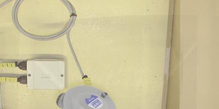
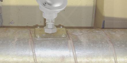
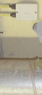
6 6. The sensor rod must not contact the opposite duct wall or any other obstacle inside the duct! In cases of need the sensor rod can be shorten to a minimum length of 70 mm. Be careful not to damage the plastic cap by doing this. The recommended length of the antenna is pipe diameter minus 10 mm. Certainly you have to insure that there will not come up any contact to the pipe, even there will grow any coating inside the pipe. The minimum length of the antenna should be 1/3 of the pipe diameter. A main rule is: the lower the dust concentration the longer the length of the antenna. 7. By monitoring a precipitator it is recommended to look for a sensor position behind the blower. If the sensor is to be used behind an electrostatic precipitator the distance to the precipitator should be a minimum of 20 m. Even so the sensor function is not affected due to vibration, the sensor should not be exposed to high vibration during a long time period. The unit above horizontal axis. Fig. 2a: Round cross-section duct The mounting socket in the middle of the side or in the middle of the top. Fig. 2b: Square cross-section duct 2.2 Installing the Sensor Once the location of the sensor has been selected, the G 1/2 female thread is welded on the duct wall and opened by drill completely. Then the G 1/2 male thread, of the sensor is screwed in until the connection is tight. Sealing has to be checked. Caution: Use the correct tool (wrench size S 27) and place it on the G 1/2 screw connector. Do not screw the sensor in by hand since the screw connector could come loose and this can damage the electronics. Do not undo the grub screw in the housing plinth. Incorrect installation will void the warranty. 6
7 + 24 V 0 V RS A RS B NO COM NC Superior 3. Electrical Connection The Dusty is fit out an internal wiring box, providing the plugs for different options: Plug number Signal name 1 V+ (24 V DC) 2 V- (0 V) 3 RS A 4 RS B 5 Relay NO 6 Relay C 7 Relay NC 3.1 Dusty as Stand Alone Dust Switch If used as a stand alone dust switch there are 4 wires to be installed. Plug number Signal name 1 V+ (24 V DC) 2 V- (0 V) 5 Relay NO 6 Relay C 7 Relay NC (alternative) 3.2 Dusty DIN Rail Converter If used the DIN Rail Converter the 4 cable wiring can still be used but has to be altered on the plugs: If the DIN Rail Converter is used the relay output of the sensor is replaced by the relay output of the DIN Rail Converter. Sensor Up to 300 m at sufficient wire cross section DIN Rail Converter 16 (+ 24 V) 15 (GND) 14 (A) 13 (B) For long distances and noisy environment shielded cables and twisted pair wiring is recommended! 7
8 3.3 Connecting Multiple Sensors using the C3-Box Up to three sensors can be connected to the DRC transmitter as an option via a C3-box to enable you to monitor large pipe cross-sections more easily. Sensor C3-Box S S Transmitter 16 (+ 24 V) 15 (GND) 14 (A) 13 (B) Sensor S Sensor S 2 m max. 300 m 3.4 Dusty M12 plug SWR Dusty M12 plug / socket Plug No. Signal 1 V (+24 V DC) 2 V (0 V) 3 ModBus A 4 ModBus B 5 Relay NO 6 Relay C 7 Relay NC 8
9 3.5 DIN Rail Converter 1 Current output 2 Current output 3 Input ma ma power supply 0 V DC 5 Not reserved 6 Alarm relay 7 Alarm relay 8 NC (Opener) C Input power supply + 24 V DC Alarm relay NO (Closer) Not reserved 10 Not reserved 11 RS interface data B RS 485- interface data A 13 Sensor connection 14 Sensor connection 15 Sensor connection 16 RS 485 RS 485 Power supply 0 V Data B Data A Sensor connection Power supply + 24 V 9
10 3.6 Use in Ex Hazardous Areas Marking DustEx: II 3D Ex ia/tc IIIC 120 C - Equipment group: 2 - Equipment category: 3 - For explosive mixtures of air and combustible dusts - IP-code 66 - Permitted process temperature -20 to 120 C Marking GasEx: II 3G Ex ia/d IIC T4 The sensor is not allowed to be used in areas of class IIC, in case of expected, intense charging processes. - Equipment group: 2 - Equipment category: 3 - For explosive mixtures of air and combustible gases - IP-code 66 - Permitted process temperature -20 to 120 C Hazardous Area DustEx-Zone 22 GasEx-Zone 2 DustEx-Zone 22 GasEx-Zone 2 Non-hazardous Area Tmax = 120 C Tmax = 60 C 10
11 ,5 81,8 14,1 Superior 4. Dimensions 4.1 Sensor ø90 91 S 27 G 1/2 81,8 66,0 14 G 1/2 S ø8 Ø8 Fig. 3: Dimensions of Dusty Dusty Ex 4.2 DIN Rail Converter Fig. 4: Dimensions of DIN Rail Converter 11
12 4.3 Dimensions C1-Box (optional) Sensor 1 Transmitter Cable gland M 16 x 1,5 Fig. 5: Dimensions C1-Box 4.4 Dimensions C3-Box (optional) Transmitter Sensor 1 Sensor 2 Sensor 3 Fig. 6: Dimensions C3-Box 12
13 5. Operation The sensor measures the dust level in a gas flow by collecting tribo-electric energy by dust particles hitting or passing near by the probe. After start-up the sensor blinks on the LEDs for information purpose: the red LED blinks to inform about the actual ModBus address, the orange LED blinks to inform about the actual factor of alert level and then the green LED starts to blink a frequency that shows the relation of actual measure against actual threshold: the lower the frequency the lower the measure. If the measure is high the frequency goes faster, if the measure is equal or higher than the alert level the LED stops blinking. Measuring levels higher than the alert level will be indicated by the yellow LED in ON status. The relay contact works as an alarm output. If the measured dust level is higher than the alert level, the relay is activated (accordingly to the yellow LED). Blinking of the red LED indicates an internal error. 5.1 Alert Level The alert level is factory pre-adjusted to a level of approx. 25 mg/m³ of organic dust material at 14 m/s of air velocity. This switching level is measured at the factory dust channel and is no absolute level for customers dust amount. To adjust to customer s desire there is one button to increase or decrease the switching level by simply changing a multiplier factor. To change the factor see chapter 5.2 One Button Operation. An internal measure value is pre-calibrated to 5 mg/m³ in factory test duct A multiplier factor is pre-set to 5 Alert level (threshold) is calculated [ factor * internal measure value ] = [ 5 * 5 mg/m³ ] Alert level = 25 mg/m³ Changing the factor to 4 means changing to alert level = 4*5 mg/m³ = 20 mg/m³ Changing the factor to 10 means changing to alert level = 10*5 mg /m³ = 50 mg/m³ Maximum factor is 30, maximum alert level = 30*5 mg/m³ = 150 mg/m³ Higher dust levels can be adjusted AutoSetup function. 5.2 One Button Operation Button S1 Pressing the button S1 will start a sequence of command options by blinking patterns. To get the desired function just RELEASE the button while it blinks accordingly! 13
14 1. Command sequence: Information only! Release the button while all three LEDs are blinking up to 5 times in common: the red LED will blink out the sensors address and the yellow LED will blink accordingly to the actual factor. 2. Command sequence: Setup of factor: Release the button while only the yellow LED is blinking: the factor is increased/decreased to the count of blinks of the yellow LED. Count the blinks to set new multiplier factor (max. 30 times) 3. Command sequence: AutoSetup! After a countdown of all 3 LEDs the LEDs are blinking up to 5 times in common: release the button while blinking of the LEDs. Sensor will enter AutoSetup mode (see chapter 5.3 for details) 4. Command sequence: Restore the factory setting: After a second countdown of all 3 LEDs the LEDs are blinking up to 5 times in common again: release the button while blinking of the LEDs to restore the factory pre-set for alert level (threshold) and factor. The LEDs will go to OFF status after the last sequence. No changes are made after the LEDs are OFF. 5.3 AutoSetup To set an individual alert level you can use the AutoSetup procedure. AutoSetup will count the actual level of dust in the duct and will store this value as internal measure value multiplied by factor as the new alert level (see chapter 5.1 alert level). To use AutoSetup procedure, make sure that the process is running a normal dust flow rate. Ensure that the device is powered on for at least 10 minutes. Open the cover of the device and initiate AutoSetup by pressing the button and release it accordingly to the description in chapter 5.2. The LEDs will flash consecutively and the sensor will look for peaks in the measurement value to keep the highest possible measurement value during the process of AutoSetup The highest peak will be the internal measure value that will be multiplied by the factor to calculate the new alert level. AutoSetup procedure takes 5 minutes to be completed, the LEDs stops flashing, green LED goes back into blinking state to indicate that the device is ready to use again. AutoSetup procedure can be cancelled by pressing the button S1 during AutoSetup procedure. No changes will be made when AutoSetup is cancelled. 5.4 DIN Rail Converter The DIN Rail Converter communicates the sensor via digital bus line, so it needs to be wired in an alternative way. If installed it takes the alert level value form the sensor as 12 ma point and zero as 4 ma point to calculate a linear function for the measure value. The measured value will be given as a current output value according to this linear function. So there is no need to set up any parameter on the DIN Rail Converter. If the alert level is changed by changing the factor or by changing the alert value due to AutoSetup procedure the gradient of the function automatically will be adjusted. The relay output of the DIN Rail Converter will show exactly the same behaviour as the relay output of the sensor. There is a simple software to use the DIN Rail Converter and its digital communication to the sensor to achieve a remote control to the sensor, e. g. if the sensor is in an inconveniently installation situation. 14
15 5.5 Relay Output Configuration By configuring the Dusty/DRC system correctly it is possible to achieve maximum monitoring and enable you to distinguish between sensor states Connection and Setting Use the NC relay connectors on the sensor (plug contacts 6+7). Plug No. Signal 1 V+ (24 V DC) 2 V- (0 V) 5 Relay NO 6 Relay C 7 Relay NC (alternative) Use the NC relay connectors on the DRC (terminals 6+7). 1 Current output 2 Current output 3 Input 4 Input ma ma power supply power supply 0 V DC + 24 V DC 5 Not reserved 6 Alarm relay 7 Alarm relay 8 Alarm relay NC (Opener) C NO (Closer) Set the Relay INV DIP switch in the sensor to the Relay INV position. In the PC-software the software parameter DIN Rail Relay is NC active (default setting). 15
16 5.5.2 Dusty Relay Function Relais geschlossen = 1 NC 0 ggf. undefiniert! NO 1 0 ggf. undefiniert! Power OFF Sensor OK MW < TRH Internal Sensor Error Sensor OFF (Kabelbruch, Busfehler etc.) Sensor OK MW > TRH Alarm In the event that a cable breaks or is crushed, the state of the relay, but not the signal can be forecast at the PLC input and may be undefined Relay/Power Output Function DIN Rail Converter Relais geschlossen = 1 NC 0 NO mA Power OFF Sensor OK MW < TRH Internal Sensor Error Sensor OFF (Kabelbruch, Busfehler etc.) Sensor OK MW > TRH Alarm Iout = 0mA Iout < 12mA Iout = 2mA Iout = 2mA Iout > 12 ma In the event that a cable breaks or is crushed, the state of the relay, but not the signal can be forecast at the PLC input and may be undefined. 16
 the DRC relay is enabled, otherwise it will be displayed in grey (disabled). Operation mixed systems is also possible.")
17 6. PC-Software The Dusty Base PC-software can communicate the system via ModBus. To achieve this the system must first be connected to the PC via the RS 486 interface. If the software finds a DIN rail on the bus (DRC = DIN rail converter) the DRC relay is enabled, otherwise it will be displayed in grey (disabled). Operation mixed systems is also possible. If the DRC has been parameterised for one sensor, the PC software will only show on sensor. If the DRC has been parameterised for multiple sensors, the display and operation will change. The changes for a system multiple sensors are summarised in the final paragraph of this section. 6.1 Info Tab This is where the COM port, Baud rate and sensor address are set: ModBus address for direct sensor communication: 2 ModBus address for DRC communication: 1 17
18 6.2 DRC Tab If a suitable DIN rail DRC is found, the DRC can be configured here: ModBus address saved in the DRC Baud rate between PC and DRC Calibration of the power output ModBus addresses of any sensors The sensors are registered their ModBus addresses in fields Sensor #1, #2, #3. If a zero is entered, the sensor is not scanned. 18
 can be observed here and the basic parameters (Parameters) for the sensor can be set.")
19 6.3 Sensor Tab Individual settings for the sensor can be made in the sensor tab. The measurements for the sensor (metering) can be observed here and the basic parameters (Parameters) for the sensor can be set. If errors are found in the sensor by internal system tests, they are marked and the sensor and the DRC display sensor error. 19
20 6.3.1 Basic Parameters A default parameter set is established for a new destination system an empty EEPROM: Parameter Default Meaning ModBus address: 2 Sensor 1 DRC TRH value: Current alarm threshold TRH factor: 5 Factor AutoSetup Time: 5 [min] time for AutoSetup function Alarm Delay: 2.5 [s] No alarm until x seconds after the threshold is exceeded Alarm Hold: 10 [s] The alarm is held for at least x seconds after the threshold value is exceeded. Alarm Hysteresis: 95 [%] Alarm cannot be regarded as able to be cancelled until it falls below a figure of x percent of the threshold value. Switch AutoSETUP Time is fix 1 Fixed, not automatically extended AutoSETUP time = AS Time 0 With each new maximum value the Auto SETUP is extended by the set AS Time HW Switch S1 is enabled 1 S1 is enabled 0 S1 is ignored DIN Rail Relais is NC 1 DIN rail relay is actuated as NC 0 DIN rail relay is actuated as NO AutoSetup AutoSetup starts a search of the alarm value: The sensor searched for the signal level which corresponds to the current dust load. See section 5.3 for a detailed description Sensor Measurement Data Dust: the measurement for the dust load Delta > TRH: Alarm threshold TRH exceeded Relais INVERT: Switch relay INV to ON so that the alarm output (flag and sensor relay) are inverted Auto Setup: an AutoSetup has been initiated and is currently running Internal Sensor Error The Error indicator shows the results of function tests which run permanently whilst the system is running. MOD conn: ModBus connection is defective Vitality Error: restricted measurement range due to coating formation (conductive) IIC disconn: IIC bus defective ADS Busy: incorrect internal timing PARA ACC: EEPROM cannot be read/written PARA CHK: EEPROM supplying inconsistent data 20

21 6.4 Trend Tab The measurement and calculation values of the sensor can be observed here. The sensor s dust value is always scaled on the left whilst the switch threshold or the relay output, for example, can be visualised on the right. 21
, use the following procedure: Program the leading sensor to address 2 in the DRC and the other sensors to 1 and 3 Connect the first")
22 7. DRC Multiple Sensors 7.1 Register Sensors To register multiple sensors on the DRC, their ModBus addresses are entered as Sensor #1, #2, #3 and sent to the DRC. If the sensors are in default mode (all at ModBus address 2), use the following procedure: Program the leading sensor to address 2 in the DRC and the other sensors to 1 and 3 Connect the first sensor, send its ModBus address (for example 3) to the sensor Connect the next sensor, send its ModBus address (for example 1) to the sensor Connect the last sensor: finished. 7.2 Leading Sensor Only the sensor registered as sensor #1 (leading sensor) is shown in the PC-software. In a 1-sensor system the DRC follows the sensor completely, in other words the sensor decides when the relay must switch and the DRC follows its relay. The power output is set to the TRH value at 12 ma and then moves around this point depending on the dust value. In a 2 or 3-sensor system, sensor #1 supplies the dust measurement and the TRH value switch threshold and the alarm delay and holding times to the DRC. The DRC uses all the dust values to calculate the arithmetic mean and then compares this mean to the TRH value of sensor #1. This means that the DRC decides in this case when its relay switches and the holding and delay times it should use. Sensor #1 only saves the values. The other sensors act as pure dust measurement suppliers but all sensors should be parameterised straight away. 22
23 Dust now shows the mean values. The single readings are displayed in an additional line. The Flag Dust > THR of the individual sensor is not shown for it any more. In trend the individual sensors are shown as thin and the average value as thicker line. 23

24 8. Maintenance For the maintenance the unit has to be removed from the process so that the sensor probe and the sensor insulation (white sleeve) can be cleaned. Hereby it s possible to prevent deposit bridges between the sensor rod and the duct wall which could induce to a function failure or short-circuit. If particles in the gas are sticky and tend to build up, the cleaning needs to be done more often. Inside the enclosure maintenance is not needed. 9. Troubleshooting 9.1 Output Relay Fails to Switch 1. Check the power supply and the connection contacts. 2. Check whether the green LED in the sensor is flashing (no alarm) or the yellow LED is lit (alarm): This indicates a problem the relay contact. 3. Check whether the red LED flashes during an active measurement: Error code!! If the sensor is still not supplying signals after these checks, contact our agents or SWR engineering Messtechnik GmbH direct. 9.2 Measured Value Not Displayed even after AutoSetup 1. Check whether the process is running normally and whether the conditions were normal during the AutoSetup procedure. 2. Check the flashing frequency of the green LED and status of the yellow LED. 3. Check the power supply and the cabling. 4. Check for bridge formation and short circuit on the specimen probe. Contact between probe and duct wall? Bridge formation between probe and duct? Casing formation around the probe due to condensate? 9.3 Relay Switches every Second: Coating Formation If the sensor detects the formation of a conductive coating between the specimen probe and pipeline, it will signal this for the duration of the coating formation but for at least one minute by switching the relay (sensor or DIN rail) every second. This instrument conforms to the following standards: Product standard - electrical equipment for measurement, control and laboratory use - EMC requirement Reference standard EN Publication year (1997) amendment(s) A1 (1998), A2 (2001), A3 (2003) 24

25 10. Technical Data Sensor Measurement objects Solid particles in a gas flow Measurement range From 0.1 mg/m 3 Range setup Pre-adjusted and automatic Process temperature Max. 140 C Ambient temperature C Pressure Max. 2 bar Air speed Min. 2 m/s Humidity 95 % RH (non-condensing) Measurement principle Tribo-electricity (electrostatic detection) Damping time 1 s Output signals 1 relay output (NO / NC) Alarm settings Alert - dust level > threshold Sensor rod Total length: 260 mm, length of stainless steel rod: approx. 194 mm Enclosure Aluminium Using in Ex-zones (Dusty Ex) Cat. 3 G/D (zone 2 gas / zone 22 dust) Protection category IP 65, Dusty Ex IP 66 Power supply 24 ± 10 % V DC Power consumption 1 W Electrical connections Internal connection box Cable (power + signal) 4 wires Process connection G 1/2 male thread Weight Approx. 0.7 kg DIN Rail Converter Power Supply 24 ± 10 % V DC Power consumption 20 W / 24 VA Protection category IP 40 according to EN Operating temperature C Dimensions 23 x 90 x 118 (W x H x D) Weight Approx. 172 g Cable cross section mm² [AWG 24-14] Current output signal ma, load < 500 W Alarm output Error output Relay toggle switch - max. 250 V AC, 1 A Digital interface ModBus RTU (RS 485) Data protection Flash memory Superior SWR engineering Messtechnik GmbH Gutedelstraße Schliengen (Germany) Fon Fax All rights reserved. EN 14/07/
Snifter. User Manual. Distributor
 Snifter User Manual Distributor Version 1.3 08/09/2009 1 Table of Contents 1. INTRODUCTION... 3 1.1 Safety... 3 1.2 Product overview... 3 1.3 How does it work?... 3 2. INSTALLATION... 4 2.1 Selecting the
ProSens Dust Measurement
 EN Operating Instructions ProSens Dust Measurement SWR engineering Messtechnik GmbH CONTENTS Page 1. Introduction.......................................................................... 3 1.1 Safety............................................................................
Snifter ATEX22 VERSION. User Manual. Distributor
 Snifter ATEX22 VERSION User Manual Distributor Version 1.4 09/09/2009 Table of Contents 1. INTRODUCTION... 3 1.1. Safety... 3 1.2. Product overview... 4 1.3. How does it work?... 4 2. INSTALLATION... 5
Sintrol Snifter A1+ Manual. Version 1.2.2
 Sintrol Snifter A1+ Manual Version 1.2.2 Table of Contents 1 INTRODUCTION... 3 1.1 Safety... 3 1.2 Product overview... 3 1.3 How does it work?... 3 2 INSTALLATION... 4 2.1 Selecting the installation location...
Sintrol Snifter A2 EX. Manual. Version 1.2.3
 Sintrol Snifter A2 EX Manual Version 1.2.3 Table of Contents 1 INTRODUCTION... 3 1.1 Safety... 3 1.2 Product overview... 4 1.3 How does it work?... 4 2 INSTALLATION... 4 2.1 Selecting the installation
S304 and S305 Dust Emission Monitors. User Manual. Distributor
 S304 and S305 Dust Emission Monitors User Manual Distributor Version 6.4 30/5/2012 Table of Contents 1. INTRODUCTION... 3 1.1 Safety... 3 1.2 Product overview... 4 1.3 Principle of operation... 4 2. INSTALLATION...
FlowJam S Ex. Bulk Flow Detection. Operating Instructions. SWR engineering Messtechnik GmbH
 EN FlowJam S Ex Operating Instructions Bulk Flow Detection SWR engineering Messtechnik GmbH CONTENTS Page 1. Function.......................................................................... 3 2. Safety..............................................................................
M-Sens 2. Online-Moisture Meter for Solids. Operating Instructions. SWR engineering Messtechnik GmbH
 EN M-Sens 2 Operating Instructions Online-Moisture Meter for Solids SWR engineering Messtechnik GmbH CONTENTS Page 1. System Overview......................................................................
M-Sens 2. Online moisture measurement for solids. Operating Instructions. SWR engineering Messtechnik GmbH PART OF THE ENVEA GROUP
 EN M-Sens 2 Operating Instructions Online moisture measurement for solids SWR engineering Messtechnik GmbH PART OF THE ENVEA GROUP CONTENTS Page 1. System overview.............................................
FlowJam Bulk Flow Detection
 EN Operating Instructions FlowJam Bulk Flow Detection SWR engineering Messtechnik GmbH CONTENTS Page 1. Function............................................................................. 3 2. Safety..............................................................................
Carbon Monoxide Transmitter
 Introduction The CO Transmitter uses an electrochemical sensor to monitor the carbon monoxide level and outputs a field-selectable 4-20 ma or voltage signal. The voltage signal may also be set to 0-5 or
RS485 MODBUS Module 8AI
 Version 1.4 15/04/2013 Manufactured for Thank you for choosing our product. This manual will help you with proper support and proper operation of the device. The information contained in this manual have
4-20mA CYBER Cyber Transmitter for flammable, toxic and IR gas detection Cyber Head Increased security in ATEX certified head
 4-20mA CYBER Cyber Transmitter for flammable, toxic and IR gas detection Cyber Head Increased security in ATEX certified head NET DRAFT version 2.1-2008 Pag. 1 4-20mA Cyber - DRAFT version 2.1-2008 Pag.
INTRINSICALLY SAFE S314X AND S315X
 INTRINSICALLY SAFE S314X AND S315X Ex SERIES DUST MONITORS Atex models S314X and S315X are not TUV approved versions User Manual Distributor Version 1.3 9.9.2009 Table of Contents 1. INTRODUCTION... 3
GMA 301. Operation Manual. Worldwide Supplier of Safety Solutions. Part Number
 Worldwide Supplier of Safety Solutions GfG Instrumentation 1194 Oak Valley Drive #20 Phone: 734-769-0573 Fax: 734-769-1888 E-Mail: info@gfg-inc.com Internet: www.gfg-inc.com GMA 301 Operation Manual Part
DMFPM-2R MULTIFUNCTIONAL
 Mounting and operating instructions Table of contents SAFETY AND PRECAUTIONS 3 PRODUCT DESCRIPTION 4 ARTICLE CODES 4 INTENDED AREA OF USE 4 TECHNICAL DATA 4 STANDARDS 4 OPERATIONAL DIAGRAMS 5 WIRING AND
MONITORING & CONTROL. the expert approach. Dust Sensors.
 Dust Sensors Continuous Trend Monitoring for Ambient Dust Improve Employee Health Conditions Protect Your Equipment Cost friendly Easy to use Low maintenance Ambient Dust Monitoring Sintrol Dumo Sintrol
Series Temperature Controller Instruction Sheet
 Series Temperature Controller Instruction Sheet Thank you very much for purchasing DELTA A Series. Please read this instruction sheet before using your A series to ensure proper operation and please keep
Danfoss gas detection unit Type GD Heavy Duty
 Data sheet Danfoss gas detection unit Type GD Heavy Duty The Heavy Duty gas detection units are used for monitoring and warning of hazardous Ammonia gas concentrations. They are intended for ATEX/ IECEx
Connections, displays and operating elements C D E G H. Installing the control unit
 1 2 3 GB Control unit 0-10 V REG-K/3-gang with manual mode Operating instructions Art. no. MTN646991 ¼ DANGER Risk of fatal injury from electrical current. All work on the device should only be carried
MO n : 12JMC rév A
 CTT8 MO n : rév A Page 2 / 18 MODIFICATIONS Rev. Description Date Checked by Approuved by Z Creation 2012/02/12 JMC LA A First issue 2012/02/14 JMC LA INDEX Page 3 / 18 GENERALITY 4 INTRODUCTION 4 ACCESSORIES
CTT8 TEMPERATURE MONITOR DEVICE
 INSTRUCTION MANUAL IM302-U v2.3 CTT8 TEMPERATURE MONITOR DEVICE GENERALITY The device of control temperatures CTT8 is used in the control of electric machine, transformer, motor, etc. where it s possible
Multi-Gas-Controller MGC2
 Page 1 Aug. 2018 Gas measuring, monitoring and warning controller based on state-of-the-art micro-technology for continuous monitoring of the ambient air to detect toxic and combustible gases, refrigerants
Analog Room Pressure Monitor RPC Series
 Description The Room Pressure Monitor is used to measure differential pressure in the range of 0.125 to 1"wc or 30 to 250 Pa. It combines precision high sensitivity silicon sensing capabilities and the
HP727S. Single speed swimming pool heat pump controller Operation manual TABLE OF CONTENTS
 HP727S Single speed swimming pool heat pump controller Operation manual TABLE OF CONTENTS 1. General Description 2. Specifications 3. Installation Instructions 4. Electrical Wiring 5. Instrument Wiring
Safety Instructions MS 10B ALARM UNIT MS 10B ALARM UNIT. Used symbols. Always observe this information to prevent damage to the device
 Safety Instructions Used symbols Important Comments Before starting with installation of the MS 10B Alarm Unit, we recommend you to read the important information beneath. Qualification The installation
OPTISENS TUR 2000 Technical Datasheet
 OPTISENS TUR 2000 Technical Datasheet Sensor for turbidity measurement in water and wastewater Rugged design for harsh applications Integrated transmitter with direct 4...20 ma output Near infrared light
Centaur TM II Cube Slave Alarm Signalling Equipment INSTALLATION GUIDE
 Centaur TM II Cube Slave Alarm Signalling Equipment INSTALLATION GUIDE General Description This guide provides a summary for installing and configuring the Centaur TM Cube Slave Alarm Signalling Equipment
TraceNet ECM Series Control System
 TraceNet ECM Series Control System ECM Operating Guide Thermon Manufacturing Company TraceNet is a registered trademark of Thermon Manufacturing Company. ECM Operating Guide 2014, 2015 Thermon Manufacturing
DPR-145 TEMPERATURE PROTECTION RELAY. DPR-145 User Manual V-2.0 ( ) PT100 INPUTS: 4 RELAY OUTPUTS: 4 RS-485 MODBUS PORT VDC SUPPLY -1-
 PT100 INPUTS: 4 RELAY OUTPUTS: 4 RS-485 MODBUS PORT VDC SUPPLY -1-") DPR-45 User Manual V-2.0 (2..206) DPR-45 TEMPERATURE PROTECTION RELAY PT00 INPUTS: 4 RELAY OUTPUTS: 4 RS-485 MODBUS PORT 9-50VDC SUPPLY DESCRIPTION DPR-45 is a precision unit designed for the temperature
DPR-45 User Manual V-2.0 (2..206) DPR-45 TEMPERATURE PROTECTION RELAY PT00 INPUTS: 4 RELAY OUTPUTS: 4 RS-485 MODBUS PORT 9-50VDC SUPPLY DESCRIPTION DPR-45 is a precision unit designed for the temperature
P2267 NETWORK INTERFACE
 P2267 NETWORK INTERFACE USER MANUAL FOR OPERATING SYSTEMS: 22031-03 23636-01 October 2009 Associated Controls (Australia) Pty. Limited 2-4 Norfolk Road Greenacre, NSW, 2190. PH +61 2 9642 4922, FAX +61
USER MANUAL FOR OPERATING SYSTEM
 P2262 ALARM PANEL USER MANUAL FOR OPERATING SYSTEM 21765-07 September 1999 Associated Controls (Aust) PTY. LTD. 29 Smith Street, Hillsdale, NSW, 2036. PH (02) 9311 3255, FAX (02) 9311 3779 Page 1 of 177
Product Manual SZ1145
 Product Manual SZ114 General Purpose Monitor Communicating Controls Description The SZ114 is a microprocessor-based monitoring and alarm interface designed to monitor up to four 1000 Ω platinum temperature
Duct and Rough Service Carbon Monoxide Sensor
 Product Identification and Overview Duct and Rough Service Carbon Monoxide Sensor BAPI s Carbon Monoxide Sensor offers enhanced electrochemical sensing with outstanding accuracy at low concentrations.
Danfoss gas detection units
 Data sheet Danfoss gas detection units Types GD Premium, Premium+, Premium Duplex, Premium Remote, Premium Flex and Premium Uptime The Premium line gas detection units are used for monitoring and warning
URD20SE. Gas detectors Carbon dioxide (CO 2 ) ATEX certified (II 2G Ex d IIC T6) Use. Operation. Ordering
 ATEX certified (II 2G Ex d IIC T6) Use. Operation. Ordering") Gas detectors Carbon dioxide (CO 2 ) ATEX certified (II 2G Ex d IIC T6) URD20SE 11 28Vdc power supply. Nondispersive infrared (NDIR) sensor designed for the detection of carbon dioxide (CO 2 ). Up to three
Gas detectors Carbon dioxide (CO 2 ) ATEX certified (II 2G Ex d IIC T6) URD20SE 11 28Vdc power supply. Nondispersive infrared (NDIR) sensor designed for the detection of carbon dioxide (CO 2 ). Up to three
Two-Channel Gas Controller
 Two-Channel Gas Controller Specifications subject to change without notice. USA 09 Page of DESCRIPTION Highly configurable, UL 0 performance-tested and -certified, and wall-mounted gas monitor; continuously
ModBus DE-1 INSTALLATION AND USER MANUAL
 ModBus DE-1 INSTALLATION AND USER MANUAL INTESIS Software, SL Distributed by DURAN ELECTRONICA S.L Tomás Bretón 50 28045 MADRID, España duran@duranelectronica.com www.duranelectronica.com 2 2010 DURAN
ELECTRONIC COMMUNICATING THERMOSTAT
 O M N I S T A T ELECTRONIC COMMUNICATING THERMOSTAT Installation Manual RC-81 Single Stage Heat/Cool Real Time Pricing System Document Number 13I00-2 January, 1997 Copyright 1997 Home Automation, Inc.
Table of Contents 1. OVERVIEW SYSTEM LAYOUT SPECIFICATIONS FUNCTION... 11
 Table of Contents 1. OVERVIEW... 3 2. SYSTEM LAYOUT... 4 3. SPECIFICATIONS... 8 3.1 SYSTEM COMPONENTS...9 3.2 PLC INPUTS AND OUTPUTS...9 3.3 FUNCTION KEYS...10 3.4 DEFAULT SET POINTS AND TIMERS...10 4.
Insulation fault evaluator EDS460-DG
 Insulation fault evaluator for localising insulation faults in DC IT systems with a number of branch circuits where high system leakage capacitances are involved Preliminary data sheet TDB108021en/09.2008
ISOMETER IRDH375. Insulation monitoring device for unearthed AC, AC/DC and DC systems (IT systems)
") Insulation monitoring device for unearthed AC, AC/DC and DC systems (IT systems) IRDH375_D00124_01_D_XXEN/07.2018 Insulation monitoring device for unearthed AC, AC/DC and DC systems (IT systems) Product
Insulation monitoring device for unearthed AC, AC/DC and DC systems (IT systems) IRDH375_D00124_01_D_XXEN/07.2018 Insulation monitoring device for unearthed AC, AC/DC and DC systems (IT systems) Product
OMC Ex interface unit. Manual. Version 1.2 August Author: Observator Instruments
 OMC-158-2 Ex interface unit Manual Version 1.2 August 2017 Author: Observator Instruments Revisions: 0.1 (October 2016) First issue 0.2 (December 2016) Prototype 0.3 (January 2017) Test release 1.0 (March
Pioneer-R16 Gas Monitor Operator s Manual
 Pioneer-R16 Gas Monitor Operator s Manual Edition 7/2/97 RKI INSTRUMENTS, INC RKI Instruments, Inc. 33248 Central Ave, Union City, CA 94587 (510) 441-5656 Chapter 1: Description About the Pioneer-R16 Gas
Air Check Ex O 2 Deficiency Monitor
 Air Check Ex O 2 Deficiency Monitor Instruction Manual Part number 99020 PureAire Monitoring Systems, Inc. 1140 Ensell Road Lake Zurich, Illinois 60047 Phone: 847-726-6000 Fax: 847-726-6051 Toll-Free:
M1000 Alarm Annunciator
 Data Sheet Alarm Annunciator Reliable Supervision and Control 10 inputs with LED indications Supports both NO/NC input contacts 10 open collector outputs Built-in siren relay Text label for alarm descriptions
Danfoss gas detection units
 Data sheet Danfoss gas detection units Types GD Premium, Premium+, Premium Duplex, Premium Remote, Premium Flex and Premium Uptime The Premium line gas detection units are used for monitoring and warning
Product Manual SZ1144
 Product Manual SZ1144 Refrigeration Temperature Monitor Communicating Controls Description The SZ1144 is a microprocessor-based monitoring and alarm interface designed to monitor up to four 1000 Ω platinum
M3092 Programmer. User s Manual. M3096B-33 E Copyright 2017 SELCO
 User s Manual Copyright 2017 SELCO SELCO Betonvej 11 - DK-4000 Roskilde Denmark Phone: 45 7026 1122 - Fax: 45 7026 2522 e-mail: selco@selco.com www.selco.com Table of contents 1 INTRODUCTION...4 2 SOFTWARE
Instruction VIBROCONTROL 850. Single channel vibration monitor. Keep it accessible for future reference.
 Instruction VIBROCONTROL 850 Single channel vibration monitor Keep it accessible for future reference. Copyright 2017 Brüel & Kjaer Vibro GmbH All rights to this technical documentation remain reserved.
Panel Mounted Fault Annunciator Series
 Panel Mounted Fault Annunciator Series BSM / USM Panel-mounted fault annunciator Annunciators for panel mounting with,,,, 0 and signal inputs Storage of the last state of inputs and sequence in the case
RCS Residential Control Systems Inc.
 RCS Residential Control Systems Inc. Model TZ16 Z-Wave Communicating Thermostat with Rev P HVAC Control Unit INSTALLATION AND OPERATION MANUAL DCN: 141-00882 Rev 02 5/18/06 This manual applies to the following
EOS INTERFACE GUIDE AND POINTS LIST For EOS BTCII Firmware Version J1239D-570 and newer
 Installation and interface must be performed by a qualified controls technician. IMPORTANT: THIS MANUAL CONTAINS INFORMATION REQUIRED FOR INSTALLATION, INTERFACE AND CONFIGURATION OF THIS EQUIPMENT. READ
MiLAB Oxygen Control MANUAL & INSTALLATION. MOC-100 Ver 3.0
 MiLAB Oxygen Control MANUAL & INSTALLATION MOC-100 Ver 3.0 Contents 1 INTRODUCTION...3 2 FUNCTIONS...4 2.1 O 2 REGULATION...4 2.2 DISPLAY BOARD...4 2.3 COMMUNICATION THROUGH PANEL...5 2.3.1 Set parameters...5
Universal Gas Detector
 Universal Gas Detector Instruction Manual PureAire Monitoring Systems, Inc. 557 Capital Drive Lake Zurich, Illinois 60047 Phone: 847-726-6000 Fax: 847-726-6051 Toll-Free: 888-788-8050 pureairemonitoring.com
SCHMIDT LED Measured Value Display MD Instructions for Use
 SCHMIDT LED Measured Value Display MD 10.010 Instructions for Use Table of Contents 1 Important Information... 3 2 Application range... 4 3 Mounting instructions... 4 4 Electrical connection... 6 5 Signalizations...
Ethernet General Purpose
 Ethernet General Purpose Technical Manual Revision 1.03 8 November 2013 Pakton Technologies IO PAE224 Ethernet GPIO Manual.docx Page 1 of 22 Revision 1.03 Last updated 8/11/2013 Table of Contents INTRODUCTION...3
Parameterisable compact fault annunciator with permanent display
 Parameterisable compact fault annunciator with permanent display FSM 10 Drop-flap fault annunciator 31.08.2010 Permanent display even on power failure Compact module for 10 alarms Supply and alarm signal
Revision November 2013 JVA Technologies. Ethernet General Purpose IO Technical Manual
 Revision 1.03 8 November 2013 JVA Technologies Ethernet General Purpose IO Technical Manual www.jva-fence.com.au Table of Contents INTRODUCTION...3 Scope and Purpose...3 Glossary...3 SPECIFICATIONS...4
Operating instructions Page 14. Refrigerator Read the operating instructions before switching on for the first time
 Operating instructions Page 14 Refrigerator Read the operating instructions before switching on for the first time 7085 039-00 LKv 5710 Content Disposal notes... 14 Description of the appliance... 14 Safety
SAPCON SMART-SSI. Continuous Speed Indicator. Users Manual. . Introduction. . General Description. . Principle of Operation. .
 CALIB CONTINUOUS SPEED INDICATOR EVALUATION UNIT ALRM 1 ALRM 2 ALRM 3 PULSE DISPLAY MESSAGES INSTRUMENT START/RESTART OVERSPEED OCCURED > UNDERSPEED OCCURED < SPEED IS
FIRERAY 5000 range USER GUIDE
 FIRERAY 5000 range USER GUIDE 0044-003-04 IMPORTANT PLEASE NOTE: The beam path MUST be kept clear of obstructions at all times! Failure to comply may result in the Detector initiating a Fire or Fault signal.
PLC INTERFACE UNIT CIT-200 INSTRUCTION MANUAL
 PLC INTERFACE UNIT CIT-200 INSTRUCTION MANUAL PREFACE Thank you for the purchase of our PLC Interface Unit CIT-200. This manual contains instructions for the mounting, functions, operations and notes when
TEMON 4-C. Doc. N MO-0368-ING TEMPERATURE MONITOR DEVICE TYPE TEMON 4-C OPERATION MANUAL. Microener- Copyright 2010 FW 2.1 Date Rev.
 TEMPERATURE MONITOR DEVICE TYPE TEMON 4-C OPERATION MANUAL Microener- Copyright 2010 FW 2.1 Date 01.12.2008 Rev. 0 1. Generality 3 2. Introduction 3 3. Accessories and Options 3 4. Installation 3 5. Connection
Air Check O 2 Sample Draw Monitor
 Air Check O 2 Sample Draw Monitor Instruction Manual Part number 99019 without horn, Part number 99029 with horn PureAire Monitoring Systems, Inc. 557 Capital Drive Lake Zurich, Illinois 60047 Phone: 847-726-6000
Operations Manual TS400. Test Station for G450/G460 Gas Detector
 TS400 Test Station for G450/G460 Gas Detector Operations Manual 1194 Oak Valley Dr, Ste 20, Ann Arbor MI 48108 USA (800) 959-0329 (734) 769-0573 www.gfg-inc.com GfG Products for Increased Safety Congratulations
ISOSCAN EDS460-DG. Insulation fault locator for DC IT systems with high system leakage capacitances
 ISOSCAN Insulation fault locator for DC IT systems with high system leakage capacitances _D00108_00_D_XXEN/05.2015 ISOSCAN Insulation fault locator for DC IT systems with high system leakage capacitances
RC-90 / RC-90B Single Stage Heat/Cool Thermostat for Zone Control Systems Installation Instructions
 RC-90 / RC-90B Single Stage Heat/Cool Thermostat for Zone Control Systems Installation Instructions DESCRIPTION The RC-90 is a precision digital thermostat designed for 24 VAC single stage heating and
Installation Manual Tracker 221
 Installation Manual Tracker 221 KSR KUEBLER AG Im Kohlstatterfeld 17 D-69439 Zwingenberg / Germany www.ksr-kuebler.com Contents About this Installation Manual...4 Description Tracker 220-series...4 Installing
1.7. Insulation fault evaluators EDS460/490 EDS461/491
 Dipl.-Ing. W. Bender GmbH & Co. KG Londorfer Str. 65 35305 Grünberg Tel.: 06401 807-0 Fax: 06401 807-59 Insulation fault evaluators EDS460/490 EDS461/491 Insulation fault evaluators with display and control
TS400. Operating Manual. Test Station for Microtector II Series (G450/G460)
") Operating Manual TS400 Test Station for Microtector II Series (G450/G460) GfG GESELLSCHAFT FÜR GERÄTEBAU MBH KLÖNNESTRASSE 99 44143 DORTMUND, Germany TEL. +49 / (0)2 31 / 5 64 00 0 FAX +49 / (0)2 31 /
Operating Manual TS400 Test Station for Microtector II Series (G450/G460) GfG GESELLSCHAFT FÜR GERÄTEBAU MBH KLÖNNESTRASSE 99 44143 DORTMUND, Germany TEL. +49 / (0)2 31 / 5 64 00 0 FAX +49 / (0)2 31 /
FlameGard 5 MSIR HART
 FlameGard 5 MSIR HART Multi-Spectral Infrared Flame Detector HART Communication with the FlameGard 5 Multi-spectral Infrared Detector The information and technical data disclosed in this document may be
RC-122BZ Two Stage Heat/Cool 2 Stage Heat / 2 Stage Cool Thermostat Installation Instructions
 RC-122BZ Two Stage Heat/Cool 2 Stage Heat / 2 Stage Cool Thermostat Installation Instructions DESCRIPTION The RC-122BZ is a precision digital thermostat designed for 24 VAC two-stage heating and cooling
RC-112 Two Speed Heat Pump 3 Stage Heat / 2 Stage Cool With Energy Efficient Control
 O M N I S T A T ELECTRONIC COMMUNICATING THERMOSTAT Installation Manual RC-112 Two Speed Heat Pump 3 Stage Heat / 2 Stage Cool With Energy Efficient Control Document Number 13I00-5 November, 1997 CONTENTS
Operations Manual TS400. Test Station for G450/G460 Gas Detector
 TS400 Test Station for G450/G460 Gas Detector Operations Manual 1194 Oak Valley Dr, Ste 20, Ann Arbor MI 48108 USA (800) 959-0329 (734) 769-0573 www.goodforgas.com GfG Products for Increased Safety Congratulations
FlameGard 5 UV/IR HART
 FlameGard 5 UV/IR HART HART Communication Manual The information and technical data disclosed in this document may be used and disseminated only for the purposes and to the extent specifically authorized
1.7. Insulation fault evaluators EDS460/490 EDS461/491
 Bender Incorporated 700 Fox Chase, Coatesville PA 1930 Tel.: (800) 356-466 Fax: (610) 383-7100 Insulation fault evaluators EDS460/490 EDS461/491 Insulation fault evaluators with display and control function
Dust Alert 75. *shown with optional external keypad and display
 Dust Alert 75 Designed to differentiate between gross failure and dust leakage from faulty/failing filter systems including bag filters Automatic internal zero and reference self-checks for regulatory
LZR -I100/ -I110. LASER SCANNERS for industrial doors. User s Guide for product version 0600 and more
 EN LZR -I00/ -I0 LASER SCANNERS for industrial doors I00: max. detection range of 9.9 m x 9.9 m I0: max. detection range of 5.0 m x 5.0 m User s Guide for product version 0600 and more SAFETY The device
Product Manual SZ1022/SZ1031/SZ1035/
 Product Manual SZ1022/SZ1031/SZ1035/ Conventional Heating & Cooling Thermostats Communicating Thermostats Description The SZ1022, SZ1031, and SZ1035, are microprocessorbased mable thermostats designed
Instructions OJ EC-Controller (Translation of the original) BA-ESR_OJ-EC /2013
 BA-ESR_OJ-EC /2013") Instructions OJ EC-Controller (Translation of the original) EN BA-ESR_OJ-EC 1.0 02/2013 Contents Contents... 2 1. Revision Index... 2 2. Introduction... 3 3. Features... 4 4. Installation... 4 5. Operation...
Instructions OJ EC-Controller (Translation of the original) EN BA-ESR_OJ-EC 1.0 02/2013 Contents Contents... 2 1. Revision Index... 2 2. Introduction... 3 3. Features... 4 4. Installation... 4 5. Operation...
System Overview F300K Compact Flame Scanner. Sensors and systems for combustion engineering.
 System Overview F300K Compact Flame Scanner Sensors and systems for combustion engineering www.lamtec.de LAMTEC F300K Compact Flame Scanner Approvals. 0085 Gas Appliances Directive 2009/142/EC, CE0085
Software Version 2.01 LEVEL MONITOR MODEL 220
 Software Version 2.01 LEVEL MONITOR MODEL 220 19 April 2000 CONTENTS 1. Introduction 1 1.1 Model Number Designation 2 1.2 Intrinsic Safety Considerations 3 2. Specification 4 3. Operation 6 3.1 Display
ENERGY LIGHT USER S GUIDE ENERGY LIGHT USER S GUIDE
 ENERGY LIGHT USER S GUIDE Release January 2001 CONTENTS 1.0 GENERAL CHARACTERISTICS... 4 1.1 MAIN CHARACTERIS TICS... 4 2.0 USER INTERFACE (CODE C5121230)... 5 2.1 DISPLAY... 5 2.2 MEANING OF THE LEDS...
OilSET-1000 (12 VDC)
") Labkotec Oy Myllyhaantie 6 FI-33960 PIRKKALA FINLAND Tel: +358 29 006 260 Fax: +358 29 006 1260 Internet: www.labkotec.fi 20.03.2009 1/11 OilSET-1000 (12 VDC) Oil Separator Alarm Device Copyright 2009
Labkotec Oy Myllyhaantie 6 FI-33960 PIRKKALA FINLAND Tel: +358 29 006 260 Fax: +358 29 006 1260 Internet: www.labkotec.fi 20.03.2009 1/11 OilSET-1000 (12 VDC) Oil Separator Alarm Device Copyright 2009
GL-CO-RFG Channel Gas Leak Alarm System
 Four Elms Road Edenbridge Kent TN8 6AB UK Features & Benefits Remote sensors for natural gas, LPG and CO 1 x SPST relay outputs DIN-rail as standard, panel mounting kit available Adjustable alarm thresholds
Replaceable LED modules. Sleep or unattended mode. Auto-silence and auto-acknowledge
 Replaceable LED modules 11 Alarm Sequences as per ISA-18.1 standard Each channel/window fully field programmable RS232 or RS485 MODBUS-RTU communication Repeat relay for each window and multifunction relays
LZR -I30. max. detection range of 30 ft x 30 ft LASER SCANNERS FOR INDUSTRIAL DOORS LZR-I Page 1 of 12
 EN LZR -I30 LASER SCANNERS FOR INDUSTRIAL DOORS max. detection range of 30 ft x 30 ft 75.5667.07 LZR-I30 0509 Page of SAFETY The device contains IR and visible laser diodes. IR laser: wavelength 905nm;
Universal fault annunciator for panel mounting
 Universal fault annunciator for panel mounting Communication over Ethernet USM - Universal-fault annunciator for panel mounting Low depth housing for panel mounting Versions with 8, 16, 32 or 48 inputs
MODEL P531, P532 AND P532UI FLAME MONITOR OPERATING MANUAL
 MODEL P531, P532 AND P532UI FLAME MONITOR OPERATING MANUAL TABLE OF CONTENTS DESIGN FEATURES OVERVIEW... 1 Viewing Head Selection...1 USER INTERFACE OVERVIEW... 1 Default Settings...2 Numerical configuration...2
Engineering Guideline. pac- Carriers Type Universal
 Engineering Guideline pac- Carriers Type 9195 Universal Integration of conventional process automation interfaces pac- Carrier The pac- Carrier reflects the intention of R. STAHL to provide state-of-the-art
TECHNICAL MANUAL CVM 20 C 5005 CV/04-99 GB
 Summary 1 CONNECTIONS... 3 1.1 TEMPERATURE PROBES...3 1.2 LOW VOLTAGE DIGITAL INPUTS...3 1.3 LIVE DIGITAL INPUTS...4 1.4 RELAY OUTPUTS...5 2 POWER SUPPLY... 6 3 SERIAL CONNECTIONS... 6 4 SOFTWARE... 7
HTC-915-CONT. Heat-Trace Control system
 Heat-Trace Control system Product overview The Raychem HTC-915 system is a compact, full-featured microprocessor-based single-point heat-trace controller. The HTC-915-CONT provides control and monitoring
HRX Technical Manual. Version 1.2
 HRX 5000 Technical Manual Version 1.2 Contents: Specification...2 Connectors...5 RS-485 Network Connectors (J6 and J7)...5 RS-232 to Printer (J19)...6 RS-232 to PC (J8)...7 TCP/IP...8 Power (J21)...9 Fire
QD6310. Fixed Gas Detector Operation Manual
 QD6310 Fixed Gas Detector Operation Manual Safety Information Before using the device, please first carefully read and follow the following information to operate the device: Please don't use the defective
PolyGard Single Point Controller SPC-X3-20XX for refrigerant gases and vapours
 PolyGard Single Point Controller SPC-X3-20XX for refrigerant gases and vapours DESCRIPTION Gas measuring, monitoring and warning controller based on state-of-the-art micro-technology with integrated sensor
Air Check O 2 Deficiency Monitor 0-25%
 Air Check O 2 Deficiency Monitor 0-25% Instruction Manual RS-485 Revision 4.05 Part number 99066 PureAire Monitoring Systems, Inc. 557 Capital Drive Lake Zurich, Illinois 60047 Phone: 847-726-6000 Fax:
INSTALLATION INSTRUCTIONS
 TT-1343 5/06b INSTALLATION INSTRUCTIONS Original Issue Date: 8/03 Model: Automatic Transfer Switches Equipped with Series 1000 Programmable Controller Market: ATS Subject: Remote Annunciator Kits GM28938-KP1,
GMA200-MT. Operation Manual. Gas detection controller for mounting rail assembly
 Operation Manual GMA200-MT Gas detection controller for mounting rail assembly GfG GESELLSCHAFT FÜR GERÄTEBAU MBH KLÖNNESTRASSE 99 44143 DORTMUND, Germany TEL. +49 / (0)231 / 564 00 0 FAX +49 / (0)231
SCAN200E USER S MANUAL
 SCAN200E USER S MANUAL Code No. 2071 1052 rev. 1.4 Code No. 2071 1052 Rev. 1.4 Page 2/16 SCAN200E User s Manual Foreword This manual is for SCAN200E Controller running software version 2.03 or later. We