eq PRIME COMMISSIONING
|
|
|
- Leslie Malone
- 5 years ago
- Views:
Transcription

1 eq PRIME COMMISSIONING
2
3 CONTENTS Unit parts...4 Safety regulations Commissioning...11 Pressure balance over rotor Handheld terminal Overview of the menu structure...14 Start page/main overview Main index/system overview Air handling unit ReCooler HP...45 Web interface...48 Modem/sms Questions and answers Alarm guide...54 Updating from an SD card...62 Limits of responsibilities Although FläktGroup has tested and reviewed the documentation contained in this manual, FläktGroup makes no warranty, neither expressed nor implied, with respect to this manual, including its quality, performance, or fitness for a particular purpose. FläktGroup shall under no circumstances be liable for direct, indirect, special, incidental or consequential damage arising from the use or the inability to use information contained in this manual. FläktGroup reserves the right to revise this publication at any time and to make changes to its content without prior notice and has no duty to provide notice to previous or current owners with respect to such revisions or changes.
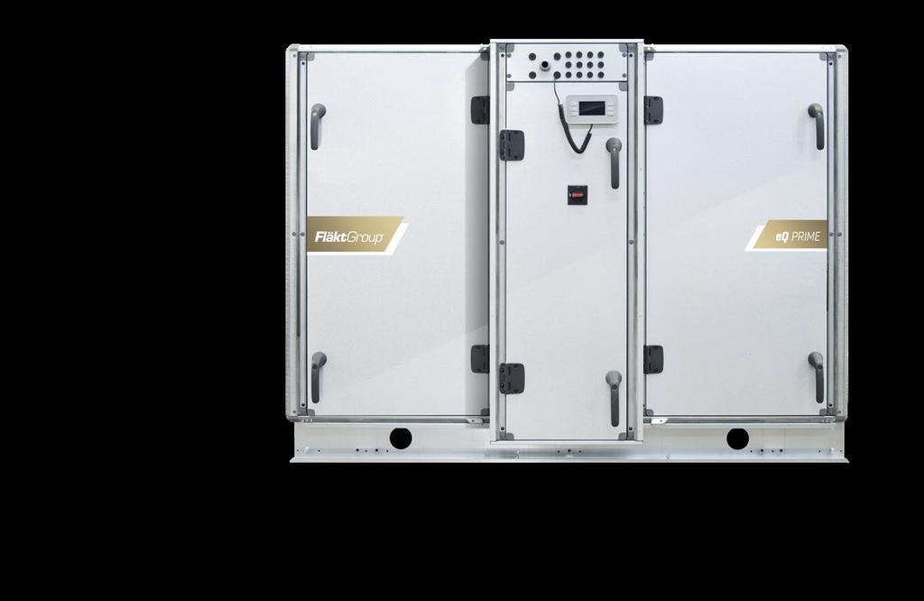
4 Unit parts eq PRIME size Simplified overview of installed components The pictured unit has the supply air at the bottom right-hand side. The unit is available with the supply air either at the top or at the bottom, and on the right or the left. 1. Outdoor air 2. Outdoor air damper with damper actuator 3. Supply air filter 4. Multifunction sensor (extract air flow, supply air filter, outdoor temperature) 5. Rotary heat exchanger 6. Drive system rotary heat exchanger 7. Drive motor rotary heat exchanger 8. Temperature sensor efficiency. Supply air fan with EC motor 10. Supply air 11. Extract air 12. Extract air filter 13. Multifunction sensor (supply air flow, extract air filter, extract air temperature) 14. Lockable main circuit breaker 15. Cable glands 16. Handheld terminal 17. AHU controller 18. Extract air fan with EC motor 1. Exhaust air damper with damper actuator 20. Exhaust air 21. Base frame FläktGroup DC_355GB _R0 4
5 Unit parts eq PRIME size Simplified overview of installed components The pictured unit has the supply air at the bottom right-hand side. The unit is available with the supply air either at the top or at the bottom, and on the right or the left. 1. Outdoor air 2. Outdoor air damper with damper actuator 3. Supply air filter 4. Multifunction sensor (extract air flow, supply air filter, outdoor temperature) 5. Rotary heat exchanger 6. Drive system rotary heat exchanger 7. Drive motor rotary heat exchanger 8. Temperature sensor efficiency. Supply air fan with motor 10. Frequency converter OJ-DV supply air 11. Supply air 12. Extract air 13. Extract air filter 14. Multifunction sensor (supply air flow, extract air filter, extract air temperature) 15. Lockable main circuit breaker 16. Cable glands 17. Handheld terminal 18. AHU controller 1. Extract air fan with motor 20. Frequency converter OJ-DV extract air 21. Exhaust air damper with damper actuator 22. Exhaust air 23. Base frame 24. Frequency converter extract air* 25. Frequency converter supply air* 1 *Optional for IE2 Motor. FläktGroup DC_355GB _R0 5
6 Unit parts eq PRIME size Simplified overview of installed components The pictured unit has the supply air at the bottom right-hand side. The unit is available with the supply air either at the top or at the bottom, and on the right or the left. 1. Outdoor air 2. Outdoor air damper with damper actuator 3. Supply air filter 4. Multifunction sensor (extract air flow, supply air filter, outdoor temperature) 5. Rotary heat exchanger 6. Drive system rotary heat exchanger 7. Drive motor rotary heat exchanger 8. Temperature sensor efficiency. Supply air fan with motor 10. Frequency converter OJ-DV supply air 11. Supply air 12. Extract air 13. Extract air filter 14. Multifunction sensor (supply air flow, extract air filter, extract air temperature) 15. Lockable main circuit breaker 16. Cable glands 17. Handheld terminal 18. AHU controller 1. Extract air fan with motor 20. Frequency converter OJ-DV extract air 21. Exhaust air damper with damper actuator 22. Exhaust air 23. Base frame 24. Option IE2 Motor - Frequency converter extract air 25. Option IE2 Motor - Frequency converter supply air FläktGroup DC_355GB _R0 6
7 Unit parts eq PRIME Active mixing Simplified overview of installed components Outdoor air 2. Supply air 3. Extract air 4. Exhaust air 5. Mixing damper 6. Return air 7. Extract air damper 1 FläktGroup DC_355GB _R0 7
8 Unit parts eq PRIME ReCooler HP Simplified overview of installed components Outdoor air 2. Supply air 3. Extract air 4. Exhaust air 5. Rotary heat exchanger - service hatch 6. Compressor 7. Inverter for compressor 8. AHU controller. Control system for the ReCooler way valve 11. Main switch disconnector 12. Electrical heater (with both auto reset, manual reset) 13. Cable glands 14. Electrical expansion valves 15. Handheld terminal for the ReCooler 16. Handheld terminal for AHU 17. Drainage FläktGroup DC_355GB _R0 8
9 Unit parts eq PRIME Counterflow Simplified overview of installed components Size Size Outdoor air 2. Extract air 3. Exhaust air 4. Supply air 5. Cable glands 6. Lockable main circuit breaker 7. AHU controller 8. Damper. Actuator 10. Heat exchanger 11. Drain tray 12. Droplet eleminator 13. Display 14. Control unit defrost FläktGroup DC_355GB _R0
10 Safety regulations Warning! Before the air handling unit is commissioned, any open connections must be protected with protective mesh. The air handling unit may not be commissioned until all electrical and mechanical safety apparatus has been installed. Take great care when opening the air purging connection for the hot water supplied to the air heater. Risk of liquid knock or steam leakage. If the eq PRIME is dismantled, FläktGroup will cease to be responsible for its compliance with the specified tightness class. The unit's doors are equipped with lockable handles. Always leave the unit locked and store the keys out of reach of unauthorised persons. Follow the separate instructions for replacement of casing parts. Local rules and regulations must always be followed. Make sure you have carefully read and understood these instructions before commissioning the unit. 2 The unit's owner or installation firm is responsible for ensuring that the valid safety rules are followed. No unauthorised persons may operate the unit. Only qualified staff members may use the unit. Make sure that all the included parts and tools used for installing the unit are removed before operating the unit. Main circuit breaker/safety circuit breaker The eq PRIME has an integrated safety circuit breaker in the electrical equipment cubicle. Access to the rotary switch is on the outside of the unit. Parts that are powered separately, such as electric heaters, require a separate safety circuit breaker. Prior to servicing or inspection, all the unit's safety circuit breakers must remain switched off for at least 1 minute before opening the inspection hatches. All the safety apparatus must be reset before restarting. The safety circuit breaker may not be used for normal starting and stopping of the unit. This must be done from the handheld terminal. FläktGroup DC_355GB _R0 10
11 Commissioning 1. Follow the instructions below regarding any parts that are included in your unit. Start by switching off the electricity supply. 2. Check that the unit is horizontal. 3. Check that the inspection doors open and close smoothly. Adjust the hinges if necessary. 4. Check that the unit is clean on the inside and outside. 5. Dampers with actuators Check that the connected dampers are in the closed position when the stepper motor is in its end position. 6. Filter Check that the filter cassettes are in place and the locking system is closed. 7. Rotor Check that the rotary heat exchanger rotates easily when pushed manually. If it does not, the rotor on the eq PRIME can be adjusted. 8. Manometers and flow metering instruments Check that the instruments are set on 0 and connected correctly (+/ ) to the test points.. For checking other functions, follow separate instructions. 10. Check that all the safety restraints have been removed. 11. Switch on the main power switch. 12. The basic control system settings are factory configured, but certain settings must be customised for each installation. Finish configuring the control system using the handheld terminal. See page 13 for further details. a) Log in. Password 2000 b) Set desired language c) Set date and time d) Set fan control setpoints e) Set temperature setpoints f) Set final pressure drop for the filters g) Set desired operating period 13. Set the operating switch to Auto. See page 15 for further details. 14. Adjust the duct system and the air terminal devices. 15. Adjust the unit's pressure balance, see page If the unit has active mixing. Run 0-calibration. See section Active mixing. 3 Questions and answers, page 51 Alarm guide, page 54 FläktGroup DC_355GB _R0 11
12 Pressure balance over rotor 4 If the eq unit is to be used in an application where it is important to prevent air leaking from the extract air to the supply air, ensure that the air leakage direction is correct. Static pressure (greater negative pressure) must be lower in the extract air than the supply air. Any risk of leakage in the wrong direction is indicated in the specifications for the eq unit if there is a value for extra restriction. On the eq PRIME, the correct leakage direction is ensured by increasing the pressure drop by installing pressure adjustment plates in front of the filter to further restrict the extract air flow. The pressure adjustment plates are perforated panels that can be spaced at various distances depending on how much air restriction is needed. The pressure adjustment plates are available as an accessory for the eq unit, and must be ordered separately. Fitting of pressure adjustment plates The pressure adjustment plates are supplied unfitted along with the unit. Separate installation instructions are included with the plates. The number of pressure adjustment plates supplied depends on the size of the unit. Enough plates are supplied to cover the whole duct opening. The number of pressure adjustment plates required for the unit depends on the degree of extra restriction needed. To fit the plates, bend them and wedge them into the filter frame. Adjusting the extra restriction The extra restriction should be adjusted after the unit and duct system are fully installed and ready for operation, so that the pressure difference between the extract air and supply air sides can be measured. Connect a differential pressure meter to the unit's measurement nipples. The nipples are intended for use with differential pressure and/or flow meters (U-tube type) over the fan and filter. If such meters are connected to the unit, they must be disconnected while adjustment is taking place. Metering must be done over the nipples on the side that is downstream from the rotor in the supply air flow. Connect one of the contacts on the pressure drop meter to the + connection on the fan section and the - connection on the filter section (see figure). Please note that it is the difference in negative pressure that is measured. 1. Start the unit on the chosen operating point. 2. Measure the pressure difference if the negative pressure is lower on the extract air side, increase the extra restriction. 3. Stop the unit. 4. Install one or several pressure adjustment plates. Repeat steps 1-4 until the pressure difference is in the correct direction. To prevent unnecessary pressure drop and energy loss, ensure that the extra restriction is no higher than is necessary in order for the pressure difference to stop at 20 Pa. Pressure balancing, of units with connection to the top above filter, must be done with a duct mounted damper with manual level actuator. Same procedure as above can be followed, where the damper is turned to more closed position to create additional air restriction. P<20Pa FläktGroup DC_355GB _R0 12
13 Handheld terminal 2. Info button Press to access Main Index. Extinguished = Stop, recooling. Green steady illumination = Normal operation. Flashes green = Startup, Night operation test, Night cooling or Night heating/night cooling. Orange steady illumination = Emergency stop and alarm with stop. Flashes orange = Fire damper exercising from Climatix. Alternating green/ orange = Manual control. 5. Up/increase Press to navigate up the list or to increase the parameter value. 4. Alarm button Function, see alarm acknowledgement. Flashes red = alarm. Red steady illumination = alarm acknowledged but persists. 1. Display Display of readings and settings. 3. ESC button Press to return to previous menu/ screen. Press to cancel the ongoing editing of a value. 6. Down/decrease Press to navigate down the list or to decrease the parameter value. 7. Enter button Press this button to enter a menu or to confirm a new reading. Hold down to go straight into the login menu if the value to be changed requires a login. 5 Navigation Use the up and down buttons (5, 6) to navigate in the handheld terminal. Press one of these buttons to move the cursor up or down to the desired row. To go into the submenu, press Enter (7). To go back to the previous menu, press ESC (3). Changing a value Place the cursor on the desired parameter using the up and down buttons (5, 6) Then press Enter (7). Set the desired value using the up and down buttons (5, 6). Confirm the change by re-pressing Enter (7). To abandon the change and return to the menu without confirming, press ESC (3). Please note: From now on in this document, navigation to a sub-menu will be illustrated with the symbol Ú. Navigation example The following example shows how to put the control unit into Auto, i.e. enable operation from the internal schedulers. 1. Place the cursor on the Main index row using the up and down buttons (5, 6). 2. Then press Enter (7) once to show the next level in the menu structure. 3. Move the cursor to the Unit row using the up and down buttons (5, 6). 4. Then press Enter (7) once to show the next level in the menu structure. 5. Move the cursor to the Operating mode row using the up and down buttons (5, 6). 6. Then press Enter (7) once to show the next level in the menu structure. 7. Move the cursor to the Manual operation row using the up and down buttons (5, 6). 8. Press Enter (7) to start editing the value.. Change the value to Auto using the up and down buttons (5, 6). 10. Confirm the selection by re-pressing Enter (7). 11. Press ESC (3) three times to return to the Start page. FläktGroup DC_355GB _R0 13
14 Overview of the menu structure The menu structure depends on which functions have been ordered. As a result, it may deviate from this overview. All functions can be accessed by using this overview. 6 Menu heading u Start page Note u Log in Password: u Main index u Unit u Main overview u Inputs u Outputs u Operating mode u Time switch program u Night cooling u Unoccupied mode u Boost u Setpoints/setting u Damper control u Balance control u Fan control u Supply air fan u Extract air fan u Summer compensation fans u Winter compensation fans u Temperature control u Setpoints u Cascade controller u Hrec damper u Crec damper u Heat recovery u Heating u Electric heaters u Cooling u Extra heating u ReCooler u Humidity control u Air quality control u Auxiliary u Controllers u Operating period u General functions u Summer and winter changeover u Alarm management u System overview u System settings u Configuration u Configuration 1 u Configuration 2 u Config. Inputs and outputs u Main overview First menu when switching on the power. Displays operating mode, mode switches and actual values for temperatures. All actual values and setpoints along with control signals and status. Status: Analogue and digital inputs. Alarm status. Status: Analogue and digital outputs. Setting of scheduler. Settings for free cooling outside operation. Settings for unoccupied mode heating and unoccupied mode cooling. Boost settings. Setpoints for fan control. Damper status and time constants. Settings for pressure balancing Supply air fan status and settings. Extract air fan status and settings. Summer setpoint compensation of fans. Winter setpoint compensation of fans. Setpoint and dead zones for the temperature controller. Controller settings for cascade control. Heat recovery damper for active mixing status and settings Cooling recovery damper for active mixing status and settings Heat recovery status and settings. Heater status and settings. Electric heater status and settings. Cooler status and settings Preheater status and settings. ReCooler status and settings. Humidity control and settings. Air quality control status and settings. Various auxiliary functions such as operational status indication. Status and settings of relevant controllers. Measured operating period and reset of runtime meter. Time and temperature settings when summer starts. Alarm resetting and alarm outputs. Time, language, software information, save/reset settings, communication. HMI, password management, diagnostics. General functions, accessories and sensors. Selection of functions and accessories. Allocation of physical input and output signals. Shortcut to the operating information menu. The following pages in this document describe the main functions that may be needed for commissioning and operation. FläktGroup DC_355GB _R0 14
15 Start page/main overview Start page When the handheld terminal is energized, the Start page will appear. You can easily reach the Start page with the INFO button (2). When INFO (2) is pressed, the Start page and the Main index will appear on alternate presses. Logging in To log in, select Log in on the Start page. The password is 2000 START PAGE Ú LOG IN Tip: You can easily reach the login page from any page in the menu structure by holding Enter (7) pressed for about 2 seconds. Start page Log in Main index Main overview Manual operation Act operating mode Outside air temp Supply air temp Act room tmp Exhaust air temp Off Off 11.5 C 20.7 C 22.6 C 22. C Manual operation To start or stop the unit manually, or to activate operation via the schedulers ( Auto ), select Manual operation from the Start page. START PAGE Ú MANUAL OPERATION 7 Main overview The Main overview menu shows a general operating status for the unit's operating system. Setpoints, actual values, control signals, status of fans, output signals to heating, cooling, heat exchanger etc., can be read off here. Exactly which values are shown will depend on the current configuration. START PAGE Ú MAIN OVERVIEW You can also reach Main overview from the Main index. MAIN OVERVIEW Main overview Act operating mode Off Time switch program Comf St1 Outside air temp 11.5 C Room temperature 22.6 C Exhaust air temp 22. C Supply air temp 20.7 C Outs air damper cmd Off Act fan step Off Act sply fan stpt 0 l/s Act sply fan value 0 l/s Supply fan 0% Act exh fan stpt Act exh fan value FläktGroup DC_355GB _R0 15
16 Main index/system overview Main index Most functions in the control unit can be accessed from the Main index. When INFO (2) is pressed, the Main index and the Start page will appear on alternate presses. Main index Unit Global functions System overview Overview IO config/rawvalues 8 System overview Date and Time To change the date and time, go to: Value date time MAIN INDEX Ú SYSTEM OVERVIEW Details DD.MM.YYYY hh:mm:ss System overview DD.MM.YYYY Language selection Application info Save / restore Communications Device Password handling hh:mm:ss HMI Diagnostic Diag object handler Version Language To change the language, go to: MAIN INDEX Ú SYSTEM OVERVIEW Ú LANGUAGE SELECTION And change the parameter HMI language. FläktGroup DC_355GB _R0 16
17 Main index/system overview Application info The Application info menu shows the software version, order number, sub-number and the date when the control unit was factory-configured. Here you can also enter the name of the application, address and city. Go to: MAIN INDEX Ú SYSTEM OVERVIEW Ú APPLICATION INFO Ú SETTINGS Place the cursor on the desired information row and press Enter to make the change. Application info FläktGroup eq fan v /00 Name Street City Settings Explanation Menu heading Unit manufacturer Soft version Date of factory setting Order number/sub-number AHU name Street address City Row for changing the above information 8 FläktGroup DC_355GB _R0 17
18 Air handling unit Air handling unit Most of the control settings are located in the Unit menu. This menu also contains Main overview, see previous page of this document. MAIN INDEX Ú UNIT Unit Main overview Inputs Outputs Operating mode Setpoints/settings Damper control Fan control Temp control Auxiliary Loop controllers Operating hours Done Inputs This menu shows detailed information from all activated inputs, divided by function, and also contains setting options for threshold values, input filters and alarm delay. INPUTS Filter eq PRIME is supplied with combined differential pressure sensors for filter monitoring and air flow measurement. Although the sensors are factory calibrated, alarm limits must be checked and, if necessary, adjusted when commissioning. Each filter is monitored with both a pre-alarm and an alarm. A pre-alarm is a Class C alarm that can be acknowledged even if the filter pressure is above the alarm limit. Alarm limit settings The alarm limit for the alarm and pre-alarm can easily be adjusted. INPUTS Ú FILTER Inputs Temperatures Pressures / flows Filter Digital inputs Digital alarms Manual operation After replacing the filter To retrieve the pre-alarm after replacing a filter, the function must be zeroed. This is done by confirming that the filter has been replaced. This is carried out using the parameter Filter changed, Pre Alm activ. The final pressure drop for the filter is normally set at double the starting pressure drop at the operating point, but at a maximum of 200 Pa. If the pressure drop is to include a prefilter, the maximum is 400 Pa. FläktGroup DC_355GB _R0 18
19 Air handling unit Fire protection unit If a fire protection unit is to be connected, it may be necessary to adjust the parameters. The control unit in eq PRIME supports connection of the following signals: Fire alarm Unit shutdown (damper exercise) Alarm from fire protection unit Different signals can be connected depending on the type of fire protection unit used. The table below shows available signals and their connection to eq PRIME. Fire protection unit Fire alarm Alarm from fire protection unit Fire protection unit with eq Prime bypass eq PRIME with bypass and seprate fire modes, can distinguish fire alarm in supply air and extract air. For this, seperate fire protection units in supply air and extract air is needed. See table below for connection to eq: Fire alarm The fire alarm is factory-configured to NC, but a bracket on the terminal block prevents the alarm from going off when there is no extinguishing equipment. The contact function or alarm delay can easily be changed from the menu. INPUTS Ú DIGITAL ALARMS Ú FIRE Unit shutdown ABAV-S N/A FCMA FICO Fire protection unit ABAV-S3 for supply air detector ABAV-S3 for extract/ room air detector FCMA-2 for supply air detector FCMA-2 for extract/ room air detector FICO-128 for supply air detector FICO-128 for extract/ room air detector Fire alarm Alarm from fire protection unit N/A N/A Unit shutdown Fire alarm mode For each fire input, it is possible to select a fire mode. Parameter InActv Stop Run Sply Run Exh Run Both Description The fire mode is inactive The unit will stop The supply fan will run in fix speed and the exhaust fan will stop The exhaust fan will run in fix speed and the supply fan will stop Both fan will run in fixed speed Ctrl St1 The fans will keep to run to fan setpoint Step 1 Ctrl St2 The fans will keep to run to fan setpoint Step 2 Alarm from fire protection unit To receive a B alarm from the fire protection unit, e.g. for an internal error, a digital or universal input must be reconfigured on the control unit. If both the external schedulers are not used, the function of one of them can be changed, e.g. digital input 3 (D3). The process is described below. 1. Log in as administrator (password 8888) 2. Go to CONFIGURATION Ú CONFIGURATION 1 3. Change EXT. CONTROL INPUT to ONE 4. Go to CONFIGURATION Ú CONFIGURATION 2 5. Change AUXILIARY INPUTtoALARM 6. Change RESTART to EXECUTE 7. Log in as administrator (password 8888) 8. Go to CONFIGURATION Ú CONFIGURATION IO's Ú DIGITAL ALARMS. Change AUX. ALARM to DI3 10. Go back to CONFIGURATION Ú CONFIGURATION IO's 11. Change RESTART to EXECUTE 12. Log in as usual (password 2000) 13. Go to AUXILIARY Ú ALARM INPUT and set the desired CONTACT FUNCTION Note that external control input 1 will now control against the fan step indicated by the parameter Fan Step, see page 22. Do not hesitate to contact FläktGroup support for advice or help with configuration. Tel FläktGroup DC_355GB _R0 1
20 Air handling unit Unit shutdown The external stop signal (e.g. for fire damper exer-cising) is factory set to NO. The contact function can easily be changed from the menu. INPUTS Ú DIGITAL INPUTS Ú EMERGENCY STOP Bypass The bypass damper shall be controlled by external fire controller. The air handling unit fans can be configured to handle higher temperatures for shorter times by activating Fire mode. For the EC-motor no activation is needed. To activate this fire mode in the inverter(danfoss) go to FAN CONTROL Ú FIREMODE, DANFOSS When function Fire mode is activated the fan operation are not reduced by high temperature or stopped by internal alarms. Note: If the inverter is damaged in this mode the warranty ceases to apply. Settings for operation and fan speed can be set in the Fan control menu: Fan Fan control control Supply fan Exhaust fan Actual step Firemode, Danfoss Fire mode 1 Supl.Fan fire setp.1 Exh.Fan fire setp.1 Fire mode 2 Supl.Fan fire setp.2 Exh.Fan fire setp.2 Rundown time el htg Disable high speed Op hours settings Fan override Flow control, unit off off off yes Run Both 80 % 80 % Run Both 0 % 0 % 180 sec C Auto 1/s FAN CONTROL Fan speed when activating the digital fire input 1 for fire/ smoke in the extract air: Supply fan fire setpoint 1 default value 80 % Exhaust fan fire setpoint 1 default value 80 % Fan speed when activating the digital fire input 2 for fire/ smoke in the supply air: Supply fan fire setpoint 2 default value 0 % Exhaust fan fire setpoint 2 default value 0 % FläktGroup DC_355GB _R0 20
21 Air handling unit Unit shutdown The external stop signal (e.g. for fire damper exercising) is factory set to NO. The contact function can easily be changed from the menu. INPUTS Ú DIGITAL INPUTS Ú EMERGENCY STOP Manual operation From the Manual operation menu, the inputs on the control unit can be overriden to the desired value. This can be used to simulate various operating conditions, e.g. during commissioning. Go to Change settings under the relevant sensor. Set the parameter Out of service to Active. The Present value can then be set as desired. Remember to restore the parameter Out of service to Passive to obtain correct measured values again. Outputs For detailed information, threshold values, etc. about all the activated outputs, go to: OUTPUTS Outputs Controller DO Controller AO Manual operation In the Manual operation menu, the outputs on the control unit can be overridden with the desired value. This can be used to simulate various operating conditions. To override an output, go to the relevant output and change the parameter Manual operation to the desired value. If changing an analogue output, the parameter Manual operation must be changed to Passive before the desired value can be set. Tip: Manual operation can be used during commissioning to simulate various operating conditions. FläktGroup DC_355GB _R0 21
22 Air handling unit Operating mode From the Operating mode menu, you can select settings for both internal and external schedulers as well as for other functions that affect operation, such as night cooling and unoccupied mode. The first row shows the activated operating mode. OPERATING MODE Operating mode Actual Manual operation Time switch program From BMS External control Night cooling Tmp start Operating hours Stop Off Comf St1 Auto Auto 10 sec Manual operation To start and stop the unit manually, and to activate operation via schedulers, select Manual operation and set the desired value. OPERATING MODE Ú MANUAL OPERATION Time switch program The control unit has three types of internal schedulers: Schedule, Calendar exception and Calendar fix off. Normally, the Schedule is first programmed according to the various preferences for each day of the week. After this, Calendar exception and Calendar fix off are used to enter exception periods such as weekends, holidays or times when the air handling unit should be shut down. The internal schedulers are configured from the Time switch program menu, but can be overriden with the parameter Manual operation. For operation via the Scheduler program, Manual operation should be set to Auto. OPERATING MODE Ú TIME SWITCH PROGRAM Week program The operating sequence is set for each day of the week in the Schedule menu. Six switchover times can be used per weekday. Time Unused switchover times must be set to passive (*.*). OPERATING MODE Ú TIME SWITCH PROGRAM Ú SCHEDULE Operating mode Eco St1 Temperature setpoint economy and fan setpoint 1 Comf St1 Temperature setpoint comfort and fan setpoint 1 Eco St2 Temperature setpoint economy and fan setpoint 2 Comf St2 Temperature setpoint comfort and fan setpoint 2 Off Unit stopped Tip: The function Copy schedule can be used if the Monday operating specifications are also to be used for Tuesday to Friday. FläktGroup DC_355GB _R0 22
23 Air handling unit Example Assume that you want to set the control unit so that the unit starts at 08:00 on Mondays for comfort operation with fan setpoint 2 and then resumes comfort operation with fan setpoint 1 at 12:00, then resumes comfort operation with fan setpoint 2 at 14:00 and shuts down at 18:00. The correct configuration for this specification is shown to the right. Please note: If you do not want the unit to start at midnight, Value 1 must be set to Off. Time 1 is locked until 00:00. Calendar exceptions In addition to the weekly plan, you can set dates, intervals and days of the week during the year in which you want to employ other operating modes or stop the unit. This is done by means of Calendar exception and Calendar fix off. For operation via calendar exceptions, use the following operating mode: Monday Day schedule Time 1 Value 1 Time 2 Value 2 Time 3 Value 3 Time 4 Value 4 Time 5 Value 5 Time 6 Value 6 Passive 00:00 Off 08:00 Comf St2 12:00 Comf St1 14:00 Comf St2 18:00 Off * :* Off OPERATING MODE Ú TIME SWITCH PROGRAM Ú SCHEDULE Ú EXCEPTION FläktGroup DC_355GB _R0 23
24 Air handling unit External schedulers The eq PRIME can be supplied with a timer, push button, CO 2 monitor and motion detector to activate extended or forced operation. The control unit can handle up to two external schedulers. On delivery, input 1 is available on terminal block and input 2 is available on terminal block The settings are set in the External control menu. External control Actual mode Tmp stpt input 1 Tmp stpt input 2 Off delay Fan steps Start/stop function Auto Economy Comfort 0.0 hrs Stage 1 No OPERATING MODE Ú EXTERNAL CONTROL The actual operating mode (Actual mode) is shown on the first row under the heading in this menu. The parameters Tmp stpt input 1 and Tmp stpt input 2 determine the temperature setpoints (Economy or Comfort) that will apply for each digital input. When input 1 is activated, the fans regulate towards step 1. When input 2 is activated, they regulate towards step 2. The parameter Fan steps is used to select the setpoints towards which the fans are to regulate when both the external schedulers are activated. If the external signal remains in place after activation, the timer function (Off delay) in the control unit should be set to 0.0 hrs. In other cases, the desired time should be set directly in the control unit. Function Timer Push button CO 2 monitor Occupancy detector Time 0.0 hours Desired time 0.0 hours 0.0 hours If a push button is used, it may be useful to have the option of interrupting the switch-off delay with the push button. This function is obtained if the parameter Start/stop function is set to Yes. In this case, alternate pulses on the inputs will start or stop/reset the timer. 10 7, min 2 15 min 1 min 60 Occupancy detector Remember to set the desired operating period directly in the occupancy detector (see figure). Frånslagsfördröjning Set the delay setting (10/60 min.) min) ställs using med the potentiometer on the längst far left till as vänster shown in enligt the figure. figur. FläktGroup DC_355GB _R0 24
25 Air handling unit Night cooling The night cooling setting is used during the summer, outside ordinary operating periods, to cool the premises at night with cool outdoor air. Function: When both the room temperature and outdoor temperature exceed the set threshold value and the difference between these threshold values exceeds the set differential, the air handling unit is started in order to cool the premises using fresh outdoor air. Coolers are disabled. If the unit was ordered with night cooling, a facade sensor and a room temperature sensor are included. Night cooling Room tmp setpoint Hysteresis Delta Min outs tmp Min run time 22.0 C 3.0 C 5.0 C 12.0 C 30.0 min Night cooling is activated when: Outdoor temperature is higher than Min outs tmp. Outdoor temperature < Room temperature - Delta. Room temperature > Room tmp setpoint + Hysteresis. Night purging is disabled when: The function has been operating for longer than the Min. operating time. External control is activated. Outdoor air temperature > Room temperature -1 C. Room temp Room tmp setpoint. To retrofit the unit with night purging, contact FläktGroup support ( ). FläktGroup DC_355GB _R0 25
26 Air handling unit Tmp start Night temp. start prevents the building from cooling down or heating up excessively at night outside normal operating times. This is controlled via a separate setpoint for heating and cooling. Function: The air handling unit starts at full power from the air heater or air cooler if the room temperature drops below or rises above the set value. If the unit was ordered with night heating, a room temperature sensor is always included. Tmp start Start stpt cooling Cooling setpoint Start stpt heating Heating setpoint Hysteresis Minimum off time Min run time 30.0 C 15.0 C 15.0 C 30.0 C 1.0 C 30 min 0.0 min Tmp start cooling is activated when Room temperature > Start stpt cooling. The Minimum off time has expired since unoccupied mode was most recently activated. Temperature control is done with Cooling setpoint. Tmp start cooling is deactivated when Room temperature < Start stpt cooling Hysteresis. The Min run time has expired since Tmp start cooling was activated. Tmp start heating (night heating) is activated when Room temperature < Start stpt heating. The Minimum off time has expired since unoccupied mode was most recently activated. Temperature control is done with Heating setpoint. Tmp start heating (night heating) is deactivated when Room temperature > Start stpt heating + Hysteresis. The Min run time has expired since Tmp start heating was activated. To retrofit the unit with Tmp start, or to change the extract air fan and damper function, contact FläktGroup support on ( ). FläktGroup DC_355GB _R0 26
27 Air handling unit Boost Boost is a function that ensures comfortable room temperature when the unit is started normally via internal schedulers. This function is not activated from the factory, but can easily be activated on site. See page 38. MAIN INDEX Ú CONFIGURATION Ú CONFIGURATION 2 Ú BOOST Boost Start stpt cooling Start stpt heating Hysteresis Compensation time 15.0 C 25.0 C 0.5 C 60 min Optimised start of heating and cooling is activated separately. Optimised start of cooling is activated when: Room temperature > Start stpt cooling + Hysteresis. The time until start via internal schedulers < Compensation time. Optimised start of cooling is deactivated when: Room temperature < Start stpt cooling. Optimised start of heating is activated when: Room temperature < Start stpt heating + Hysteresis. The time until start via internal schedulers < Compensation time. Optimised start of heating is deactivated when: Room temperature > Start stpt heating. If the function is activated without the room temperature sensor connected, the measured value from the air temperature sensor will be used instead. This function is always included in eq PRIME. FläktGroup DC_355GB _R0 27
28 Air handling unit Main setpoints To set the desired Main setpoints for temperature and fans, go to: SETPOINTS/SETTINGS This menu shows the Main setpoints for temperature and fans. Go to All settings to access the settings for sub-level functions. The content of this menu is changed according to the selected temperature and fan control settings. The active operating mode from the internal schedulers is shown directly under All settings. Temperature setpoints Heating setpoint for comfort operation (Comfort htg stpt) Heating setpoint for economy operation (Economy htg stpt) Dead zone between heating and cooling during comfort operation (Comfort tmp deadz) Dead zone between heating and cooling during economy operation (Economy tmp deadz) Lowest permitted supply air temperature (Supply tmp min stpt) Highest permitted supply air temperature (Supply tmp max stpt) Note: Cooling setpoint = Heating setpoint + dead zone. Main setpoints All settings Time switch program Comfort htg stpt Comfort tmp deadz Comfort htg stpt Economy tmp deadz Supply tmp min stpt Supply tmp max stpt Sply fan st1 stpt Sply fan st2 stpt Exh fan st1 stpt Exh fan st2 stpt Comf St C 22.0 C 22.0 C 22.0 C 22.0 C 22.0 C 250l/s 600l/s 250l/s 600l/s Fan setpoints Setpoint supply air fan step 1 (Sply fan st1 stpt) Setpoint supply air fan step 2 (Sply fan st2 stpt) Setpoint extract air fan step 1 (Exh fan st1 stpt) Setpoint extract air fan step 2 (Exh fan st2 stpt) Note: Fan setpoints are given in either l/s or Pa, depending on the activated control function. Important! Remember that electric heaters require at least one minimum air flow value. Refer to the minimum flows in the table on the next page. FläktGroup DC_355GB _R0 28
29 Air handling unit Minimum flows for duct-mounted electric heaters Connection Ø/WxH Output, kw Variant 1 Min. flow m 3 /s Ø Ø ( ) Ø x x x x Connection Ø/WxH Output, kw Variant 2 Min. flow m 3 /s Ø Ø ( ) Ø x x x x Minimum flows for air handling unit-mounted electric heaters Unit size aaa Min. flow m 3 /s Connection Ø/WxH Output, kw Variant 3 Min. flow m 3 /s Ø Ø ( ) Ø x x x x Rectangular air heater (400x400) with a circular connection for output variant 3 (15 kw) 2 Rectangular air heater (500x500) with circular connection, all output variants. FläktGroup DC_355GB _R0 2
30 Air handling unit Fan control All the necessary fan settings can be set from the Fan control menu. FAN CONTROL Ú This menu includes settings for: Alarm for deviation from fan setpoint Fire protection function Rundown of electric heater Disabling of fan step 1 at low outdoor temperatures Operating hours alarm Fan control Supply fan Exhaust fan Act fan step Fire mode Fire setpoint Rundown time el htg Disable high speed Summer comp Winter comp Op hours settings Off Off Off Stop 80% 180 sec C 0.0% 0.0% Deviation alarm The Deviation alarm monitors the unit's ability to keep to the configured fan setpoints. The supply and extract air fans are set separately. Supply air fan Deviation alarm Alarm Min limit Maximum deviation Start up delay Passive 20 l/s 300 l/s 180 sec FAN CONTROL Ú SUPPLY FAN Ú SETPOINTS/SETTINGS Ú DEVIATION ALARM Extract air fan FAN CONTROL Ú EXHAUST FAN Ú SETPOINTS/SETTINGS Ú DEVIATION ALARM Settings The lowest permitted value for feedback signal, i.e. flow or pressure (Min limit). Maximum permitted deviation from fan setpoint (Maximum deviation). Alarm delay during startup (Start up delay). Bear in mind that there is often a simple explanation why the deviation alarm is triggered. For troubleshooting tips, see Questions and answers on page 48. FläktGroup DC_355GB _R0 30
31 Air handling unit Fire mode The control unit in eq PRIME can be configured for various Fire modes, i.e. how the fans are controlled in the event of a fire alarm. For possible choices, see below and on the next page. FAN CONTROL Ú FIRE MODE The fire setpoint value refers to a constant control signal linked to one or both fans as indicated above. The value is entered in the control unit as a percentage ( %) of the maximum control signal. Note that the same control signal is linked to both fans if the control unit is configured so that both fans are controlled towards the fire setpoint. FAN CONTROL Ú FIRE SETPOINT Rundown If the control unit has been configured for a electrical heater, rundown will occur before the unit stops. Rundown is factory-set to 3 minutes, but this can easily be changed with the following parameters: FAN CONTROL Ú RUNDOWN TIME EL HTG Fan control Supply fan Exhaust fan Act fan step Fire mode Fire setpoint Rundown time el htg Disable high speed Summer comp Winter comp Op hours settings Fire mode Stop Run Sply Run Exh Run Both Ctrl St1 Ctrl St2 Off Off Off Stop 80% 180 sec C 0.0% 0.0% Explanation Both fans off. Supply air fans are controlled towards the fire setpoint. Extract air fan stopped. The extract air fan is controlled towards the fire setpoint. Supply air fan stopped. Both fans are controlled towards the fire setpoint. Both fans regulate towards the fan setpoints in step 1. Both fans regulate towards the fan setpoints in step 2. Disable high speed To reduce the risk of heat loss, the control unit can be configured to disable Fan stage 1 at low outdoor temperatures. The desired threshold value is set with the following parameters: FAN CONTROL Ú DISABLE HIGH SPEED Remember to also set Fan stage 2 when this function is used. FläktGroup DC_355GB _R0 31
32 Air handling unit Outdoor temperature compensation fan setpoints This function adjusts the fan setpoints up or down according to the outdoor temperature. This is done by means of break points in the Summer comp and Winter comp menus, which are accessed via the Fan control menu. FAN CONTROL Fan control Supply fan Exhaust fan Act fan step Fire mode Fire setpoint Rundown time el htg Disable high speed Summer comp Winter comp Op hours settings Off Off Off Stop 80% 180 sec C 0.0% 0.0% Börvärdesförändring Setpoint adjustment [%] Delta Summer Delta Winter Outside air temp Outs air tmp end Winter Outs air tmp start Winter Outs air tmp start Summer Outs air tmp end Summer [ C] FläktGroup DC_355GB _R0 32
33 Air handling unit Summer comp fan From this menu, fan setpoints can be offset at high outdoor temperatures. FAN CONTROL Ú SUMMER COMP If Delta is negative, the setpoints are lowered. If Delta is positive, the setpoints are raised. Summer comp fan Outs air tmp start Outs air tmp end Delta 25.0 C 30.0 C 0.0% Winter comp fan From this menu, fan setpoints can be offset at low outdoor temperatures. FAN CONTROL Ú WINTER COMP Winter comp fan Outs air tmp start Outs air tmp end Delta 5.0 C C 0.0% If Delta is negative, the setpoints are lowered. If Delta is positive, the setpoints are raised. FläktGroup DC_355GB _R0 33
34 Air handling unit Temp control The Temp control menu can be used to select all the necessary temperature settings. Temp control Act controlled tmp Tmp setpoints 21. C TEMP CONTROL Cascade controller 22.0 C 20.0 C The actual temperature value, current setpoints and control signals for the functions in the control sequence are shown directly in this menu. Heat recovery Heating Cooling 0% 0% 0% Some of the settings in the sub-menus: Temperature setpoints Max. and min. supply air temperature Weather compensation for temperature setpoints Cascade controller settings Controller settings Alarm settings etc. Pre heater A pre heater is used to warm up cold outdoor air before the air enters the AHU. This function is used during periods of low outdoor temperatures to prevent frost from building up in the filter. The pre heater controller operates with a separate set point that is adjustable from the HMI. El Heating 2 Controller Output signal Command Extra Seq setpoint 0 % 0 % Off -5.0 C TEMP CONTROL Ú HEATING 2 / EL HEATING 2 Alarm Start stage 1 Stage hys off OK 20 % 10 % Max limitation fan FläktGroup DC_355GB _R0 34
35 Air handling unit Weather compensation, temperature This function adjusts the temperature setpoints up or down according to the outdoor temperature. Increasing the temperature setpoints to compensate for high or low outdoor temperatures improves indoor comfort in cold winter and hot summer weather. It also saves energy in summer. The setpoints are changed by means of break points in the Summer comp and Winter comp menus, which are accessed via the Temp control menu. Börvärdesförändring Setpoint adjustment [%] Delta Summer Delta Winter Outs air tmp end Winter Outs air tmp start Winter Outs air tmp start Summer Outside air temp Outs air tmp end Summer [ C] FläktGroup DC_355GB _R0 35
36 Air handling unit Humidity control The controller settings for humidification and dehumidification can be viewed and changed in the Humidity control menu. HUMIDITY CONTROL Humidification can be disabled during the summer with the parameter Summer disable. Humidity control Act controlled hum Setpoints Max controller spl... Humidification Dehumidification Summer disable 25.1 %rh 0 % 0 % No Go to setpoint page with all setpoints related to humidity control. HUMIDITY CONTROL Ú SETPOINTS Hum setpoints Act controlled hum Room Act dehum stpt Act hum stpt Act sply dehum stpt Act sply hum stpt Dehum setpoint Hum setpoint Sply hum min stpt Supply hum max stpt Sply hum dev alarm Room hum dev alarm 0.0 %rh 60.0 %rh 40.0 %rh 60.0 %rh 40.0 %rh 60 %rh 40 %rh 30.0 %rh 70.0 %rh Control modes Room Supply Room Cascade Room/exhaust humidity control only Supply humidity control only Cascade control of humidity For room cascade mode, the humidity in the room will set the setpoint in the supply air. Supply air humidity will be limted by a max and min setpoint. In dehumidification mode, the cooling signal will consist of the maximum value from the cooling controller and the dehumidification controller. Deviation alarm It is possible to activate deviation alarm for the humidity. It monitors the unit s ability to keep the humidity setpoints. The room humidity and the supply humidity are set separately. Supply humidity Room humidity HUMIDITY CONTROL Ú SETPOINTS Ú SPLY HUM DEV ALARM HUMIDITY CONTROL Ú SETPOINTS Ú ROOM HUM DEV ALARM FläktGroup DC_355GB _R0 36
37 Air handling unit Air quality control Air quality control is available with normal or inverted function. With Normal Function, the fan setpoints are increased proportionally when the carbon dioxide level exceeds the set Setpoint. In this case, the carbon dioxide sensor should be installed in the room or in the extract air. Inverted function is used when a carbon monoxide sensor has been installed in the outdoor air. The fan setpoints are decreased proportionally if the carbon monoxide level exceeds the set Setpoint. The proportional adjustment of the setpoints is equal for both fans. Air quality control Controller Function Setpoint 0 % Normal 800 ppm AIR QUALITY CONTROL This menu includes settings for Setpoint, choice of Function and Controller. Note that the gain must be negative (measured values higher than the setpoint value must be negatively pressurised). Active mixing Active mixing is a flow controlled recirculation. The function is initialized with minimization of the differential pressure over the mixing damper. This is done with the extract air damper (optimal) and the outdoor damper, depending on the pressure setup of the installation. After that, the mixing damper and the outdoor damper are controlled in parallel for mixing the air. The exhaust fan is controlled to keep the flow balance in the unit. If full recirculation is allowed the exhaust air fan will stopped and the mixing damper will be fully open. 0-calibration For correct function of the active mixing, the unit must make a 0-calibration when commissioning the unit. To execute a 0-calibration set the Manual operation to Auto and go to: TEMP CONTROL Ú HREC DAMPER Ú SETTINGS Ú START Hrec damper Controller Output signal Recovery value Crec damper Controller Output signal Recovery value cooling FreshAir Limit/settings Min fresh air Min flow fresh air Controller, Q-min Output signal Q-min Out,signal Settings 0 % 100 % 100 % 0 % 100 % 100 % 0 % 4 % 14 1/s 0 % 0 % 0 % The air handling unit will first run in stable condition in max speed and then in fan setpoint Step 1. FläktGroup DC_355GB _R0 37
38 Air handling unit Settings can be done in the Heat recovery damper menu: TEMP CONTROL Ú HREC DAMPER There is a lower limit for the outdoor air flow during mixing in the controller. This limit can be set in sevral ways. Balance control Prs.balance setpoint Force damp. at start Max Bal.control time Max Bal. Prs. deviation 10 Pa 60 sec 60 sec 10Pa Parameter Unit Description Min fresh air % Limitation of the the mixing controller output value. Min flow fresh air l/s A controller is controlling the minimum amount of outdoor air in l/s to the supply air. Air quality setpoint ppm The air quality setpoint in the room is limiting the active mixing controller output. See page 34 for air quality settings. Balance Control Exh. Pres.balance Exh.damp Min. Prs.balance Exh.damp Exh.Bal. Contrl. Invert Balance Control outsideair Pres.balance Outsidedamp Min. Prs.balance Outs.damp Outs.Bal. Contrl. Invert 100 % 0 % 50 % Active 100 % 0 % 50 % Active Active mixing pressure balancing The settings for pressure balancing can be found in the Balance control menu: DAMPER CONTROL Ú BALANCE CONTROL Prs.balance setpoint is the setpoint when pressure balancing over mixing damper. When the pressure is within the setpoint as near as the max deviation, Max Bal. Prs. deviation, the mixing damper is starting to open. If the setpoint is not achieved within a time period, Max Bal. control time, the mixing damper is opened. FläktGroup DC_355GB _R0 38
39 Air handling unit Auxiliary The control unit has various auxiliary functions. These functions are managed from the Auxiliary menu. Auxiliary Op mode output Op mode outp select On Off AUXILIARY The eq PRIME is delivered with only the configurable operating mode output activated. For this reason, setting and reading of this function should be done via the Auxiliary menu. This output can be very useful if the unit's operation will affect other equipment. Do not hesitate to contact FläktGroup support for advice and assistance. Tel Loop controllers From the Loop controllers menu, you can adjust all thecontrollers for the control unit. LOOP CONTROLLERS This menu contains settings for Gain, integration time constant and derivative time constant. Note that the gain must be negative for cooling but positive for other controllers. Loop controllers Supply fan Exhaust fan Casc controller tmp 22.0 C Heat recovery Heating Heating frost Cooling 0% 0% 20.0 C 0% 0% 0% 0% However, the cascade controller settings are different from the other settings. In this case, it is not possible to set the actual PID controller. Instead, High limit and Low limit can be set for the supply air temperature. It is also possible to set Load compensation, which causes constant offsetting of the cascade controller's output signal (i.e. of the calculated supply air setpoints). FläktGroup DC_355GB _R0 3
40 Air handling unit Operating hours The control unit in the eq PRIME is equipped with operating time meters for fans and circulation pumps. They can be used to signal a need for maintenance, e.g. filter replacement. OPERATING HOURS If you want the control unit to emit an alarm signal after the fans have been operating for a certain period, this function must be activated during commissioning. OPERATING HOURS Ú FAN SETTINGS Operating hours Supply fan Reset Exhaust fan Reset Fan settings Heating pump Reset Cooling pump Reset 0 hrs Execute 0 hrs Execute 0 hrs Execute 0 hrs Execute The desired alarm time must be set with a parameter in the same menu. Alarms Alarms are indicated by a red LED on the alarm button (4) on the handheld terminal. Press the alarm button once to show the alarm on the display. Press the alarm button once more to show the entire alarm list. Alarms are presented in clear text in the alarm list. Scroll through the alarm list using the up and down buttons (5, 6). Repeatedly pressing the alarm button causes the alarm menus to circulate in the following order: ALARM LIST DETAIL Ú ALARM LIST Ú ALARM HISTORY Ú SETTINGS Ú ALARM LIST DETAIL... Return to the previous menu using the ESC button (3). Alarm acknowledgement Acknowledge an alarm by logging in and then pressing the alarm button (4) twice so that Alarm list appears on the display. The Acknowledge function is at the top of this page, along with the number of alarms. Place the cursor on this row using the up and down buttons (5, 6). Press the Enter button (7) and select Active to acknowledge an alarm. If the alarm persists, the light on the alarm button will shine continuously. Alarm list Acknowledge + MB comm alarm: Alarm + Exhaust air flow: Alarm 2 FläktGroup DC_355GB _R0 40
41 Air handling unit Activation/changing of functions The control unit in the eq PRIME has powerful standard software that allows functions to be activated, changed or removed retroactively. This is done from the Configuration menu. To access this menu, it is necessary to log in using Below is a list of the most common changes. Note that a new sensor may be required after making a change. Do not hesitate to contact FläktGroup support for further information, advice or help regarding settings. Tel It is usually necessary to restart the control unit in order or the changes to be applied. This can be done with a parameter at the bottom of each sub-menu. Function Search path (Parameter) Comment Weather compensation, temperature (Summer/Winter compensation) MAIN INDEX Ú CONFIGURATION Ú CONFIGURATION 2 Ú SU/WI COMP TMP For function description, see page 33. Outdoor temperature compensation fan setpoints Control mode fans Control mode, temperature MAIN INDEX Ú CONFIGURATION Ú CONFIGURATION 2 Ú FAN COMP OUTS TMP. MAIN INDEX Ú CONFIGURATION Ú CONFIGURATION 1 Ú FAN CONTROL MODE MAIN INDEX Ú CONFIGURATION Ú CONFIGURATION 1 Ú TMP CONTROL MODE For function description, see page 30. Available choices for eq PRIME: Fixed speed (Fixed speed) Flow (Flow control) Pressure (Pressure control) SupplySlv (Pressure control extract air, flow control supply air) ExhaustSlv (Pressure control supply air, flow control extract air) Available choices for eq PRIME: Supply air (Supply air control) RmSplyC (cascade control, room) ExhSplyC (Cascade control, extract air) RmSplyC Su (Summer room control, winter supply air control) ExSplyC Su (Summer extract air control, winter supply air control) Room (Room temperature control) Extract air (Extract air temperature control) HOTC (Heat exchanger optimised temperature control) Night cooling MAIN INDEX Ú CONFIGURATION Ú CONFIGURATION 2 Ú NIGHT COOLING For function description, see page 23. Unoccupied mode MAIN INDEX Ú CONFIGURATION Ú CONFIGURATION 2 Ú TMP START For function description, see page 24. Boost MAIN INDEX Ú CONFIGURATION Ú CONFIGURATION 2 Ú BOOST For function description, see page 25. FläktGroup DC_355GB _R0 41
42 Air handling unit Cooling recovery Filter alarm MAIN INDEX Ú CONFIGURATION Ú CONFIGURATION 2 Ú HREC CLG RECOVERY MAIN INDEX Ú CONFIGURATION Ú CONFIGURATION 1 Ú FILTER ALARM Start Outdoor temperature > Room temperature + 2K and Room temperature > Room setpoint + 1K Stop Outdoor temperature Room temperature or Room temperature Room setpoint The filter alarm on the eq PRIME is always activated at the factory (Supply air-ai+extract air-ai) CO 2 control MAIN INDEX Ú CONFIGURATION Ú CONFIGURATION 2 Ú FAN COMP AIR QUAL IPSUM MAIN INDEX Ú CONFIGURATION Ú INTEGRATIONS Ú IPSUM SYSTEM Function: The fan and/or temperature setpoints are controlled to achieve minimum energy consumption by the IPSUM system Humidity control mode MAIN INDEX Ú CONFIGURATION Ú CONFIGURATION 2 Ú HUM CONTROL MODE For control mode function see page 34 [ref to Humidity control]. Humidity control UNIT MAIN INDEX Ú CONFIGURATION Ú CONFIGURATION 2 Ú HUM CONTROL UNIT Change between absolute or relative humidity setpoint. Dehumidity or temperature priority MAIN INDEX Ú CONFIGURATION Ú CONFIGURATION 2 Ú DEHUM TEMP PRIO Give the temperature setpoint priority over the humidity setpoint. If heating valve position reaches 0 % it will reduce the dehumidification. Deviation alarm MAIN INDEX Ú CONFIGURATION Ú CONFIGURATION 2 Ú HUM DEVIATION ALARM Activation of humidity deviation alarm. FläktGroup DC_355GB _R0 42
43 Air handling unit Pressure/flow sensor Differential pressure sensors are supplied as separate accessories when the eq PRIME has been ordered with pressure control. The flow sensor is always factoryinstalled (included in multifunction sensor). The settings differ slightly between the pressure and flow sensors. Duct pressure sensor FläktGroup's duct pressure sensor has a settable measuring range. To obtain the best possible measurement signal from the differential pressure sensor, the lowest possible measuring range should be chosen. This setting should be performed for both the sensor and the control unit. 500Pa 1000Pa 1500Pa 2250Pa Jumper Bygel 1 Jumper Bygel 2 Jumper Bygel 3 The measuring range for the sensor is set with jumpers. The lowest measuring range (500Pa) is obtained by removing jumpers 1, 2 and Pa 3750Pa 5000Pa 7000Pa Jumper Bygel 1 Jumper Bygel 2 Jumper Bygel 3 Zero point calibration NOTE! Zero point calibration must be performed on the sensors during commissioning. They should then be zero calibrated annually. The sensors should have been energized for approximately one hour before calibration is performed. Disconnect the pressure hose from the sensor. To start calibration press the button next to the pressure range jumpers for approximately 4 seconds, until the LED lights up. When the LED goes out again, calibration is complete and the pressure hose can be reconnected. Response time The response time is also set using the button beside the jumpers. A short press of the button changes between 0.8 and 4 seconds. If the LED flashes 3 times after pressing the button, the response time is 0.8 seconds. If it flashes twice, the response time is 4 seconds. For optimum operating stability, a response time of 4 seconds is recommended. >4s LED: long blink... Zeroing LED: 3 x short blink means 0,8 s selected <1s <1s LED: 2 x long blink means 4 s selected FläktGroup DC_355GB _R0 43
44 Air handling unit Control unit To set the equivalent measuring range in the control unit, go to: OVERVIEW IO CONFIG/RAWVALUES Ú PRESSURES/FLOWS and set the same measuring range as in the sensor for supply air pressure and extract air pressure, respectively. IO conf press/flows HW IO: Pos: Fact: Scale: Supply air pressure X7 500Pa Type: 0-10V Exhaust air press X8 500Pa Type: 0-10V Modbus Fact: Flow sensor The flow sensors are installed, connected and configured at the factory. For this reason, they normally do not need to be set on site. However, it is still necessary to mention zero point calibration, flow calculation and temperature correction. Zero point-calibration Zero point-calibration can be performed, if necessary, by means of a push button placed underneath the sensor cover. Zero point calibration must be performed on sensors subjected to high overpressure. Flow calculation The control unit calculates the flow according to the following formula: q = 1 k Δp m3 /s In which q is the flow and Δp is the differential pressure from the sensor. The k factor is shown on the air handling unit data plate and in the control unit's menu. OVERVIEW IO CONFIG/RAWVALUES Ú PRESSURES/FLOWS IO conf press/flows Modbus Fact: Supply Flow Pressure Present value 0Pa Return Flow Pressure Present value 0Pa Temperature correction The flow scale on the display instrument and flow formula above apply to air at a temperature of +20 C. At other air temperatures the flow must be corrected using the formula: q = the actual flow through the fan, q 20 = the flow reading t = current temperature in C q = q (273+t) 20 m 3 /s 23 FläktGroup DC_355GB _R0 44
45 ReCooler HP ReCooler HP The ReCooler HP is an integrated reversible cooler. Depending if the air handling unit is in heating or cooling demand the ReCooler HP will alter between cooling and heating mode. Cooling Controller 0% Output signal 40% Disable by outs tmp 12.0 C Defrost fan compensating Under some conditions the ReCooler HP will go to a defrost mode during a couple of minute. During this time the fans will go on reduced speed. This reduced fan speed is configurable for each fan. The settings are % of actual fan setpoint. TEMP CONTROL Ú COOLING The ReCooler HP status is shown in the eq display, such as the cooling/heating demand and the actual operating status. If there is an alarm in the ReCooler HP, it could be viewed in the eq display. Act. Opstatus Alarm number Alarm No alarm Rotor alarm Comp. alarm Diff.press alarm Max.pressure Inverter alarm Inverter offline Min.pressure EEV fault Discharge temp Discharge press Suction pressure Superheat alarm High env. limit Low env. limit Stop LowEnv.limit Description No alarm Rotor alarm Compressor start alarm Differential pressure alarm Max. Discharge pressure alarm Frequency drive (power+) alarm Frequency drive offline alarm Min. Suction pressure alarm Expansion valve alarm (sensor) Discharge temperature alarm (sensor) Discharge pressure alarm (sensor) Suction pressure alarm (sensor) Low superheat alarm High envelope limit (pressure) Low envelope limit (pressure) 10 FläktGroup DC_355GB _R0 45
46 ReCooler HP Cooling/heating circuit 1: :1-3 2:1-3 2 VVX 3:1-3 3 Room Room Cooling mode Heating mode 15 15:1-3 12:1-3 13: :1-3 16: :1-3 10: : : : :1-3 17:1-3 11:1-3 14:1-3 POS PCS ITEM 1:1-3 1 Exhaust air coil 2:1-3 1 Inlet air coil 3: way valve 4:1-3 1 Compressor Size Size circuit 2 circuits 5:1-3 1 Liquid separator 6:1-3 1 Reciver 7:1-3 1 Filterdrier 8:1-3 1 Sightglass :1-3 1 EEV 2 10:1-3 1 EEV 1 11:1-3 1 High pressure sensor 12:1-3 1 Low pressure sensor 13:1-3 1 Suction temp sensor 14:1-3 1 Liquid temp sensor 15:1-3 1 Discharge temp sensor 16:1-3 1 Low pressure service connector 17:1-3 1 High pressure service connector 18:1-3 1 Extract air sensor 1 1 Rotor FläktGroup DC_355GB _R0 46


")


47 ReCooler HP Hand terminal ReCooler HP The ReCooler HP is equipped with an own display. This display is used for detail information of the Re-Cooler HP system. When the unit is powered up the following screen is displayed. The user is presented with the option to select a desired language. The ENTER button is used to change through the list of available languages and the ESC button selects the highlighted language. The home screen displays information related to the current status of the unit. This screen displays information related to the current status (operation mode) of the coils (condensing/evaporating) and whether the AHU is configured with supply air in the upper or lower level. 10 Displays information related to the temperature and pressure of the system. Displays information regarding the status of the unit. Select signal reference for controlling the ReCooler. Analog signals or Modbus for controlling from BMS. eq air handling unit with control uses Modbus. Software information of the system. Reset alarms can be restarted 5 times in 24 hours. If more alarms are generated then manual reset will be necessary. To restart the unit in this case press 5 sec on the Alarm button on the handheld terminal for the ReCooler HP. FläktGroup DC_355GB _R0 47
48 Web interface Two web interfaces are available for the eq PRIME for monitoring, operation and parameterisation via standard web browsers. This section of the instructions describes the integrated web interface that is always included in the control unit. The SmartWeb accessory is described in the separate instructions entitled 02 SE. Procedure 1. Connect the control unit to an Ethernet network, via the RJ45 connector. 2. Configure the TCP/IP settings in the control unit. 3. Open the web browser, enter address and log in. TCP/IP settings Go to: MAIN INDEX Ú SYSTEM OVERVIEW Ú COMMUNICATION Ú TCP/IP T-IP Ethernet 11 Explanation DHCP Shows the type of address allocation Active: The DHCP server allocates addresses. Passive: Fixed IP address. Actual IP: Shows the actual IP address. Actual Mask: Shows the actual mask address. Act. Gateway: Shows the actual gateway address. Given IP: The new IP address is specified here. Finish with #. Given Mask: The new mask address is specified here. Finish with #. Given Gateway: The new gateway address is specified here. Finish with #. 100 MBit: Actual transmission rate Active: rate of 100 Mbit Passive: rate of 10 Mbit Name: Shows name of controller. MAC: Shows controller's MAC address. Link: Shows Ethernet connection. Passive: No Ethernet connection. Active: Ethernet connection. User name: For logging on to web interface. Finish with #. Password: For logging on to web interface. Finish with #. FTP user name: For FTP connection (not used). FTP password: For FTP connection (not used). Restart: Restart is always required after making changes in this menu. Change to Execute to restart the control unit. TCP/IP DHCP Passive Actual IP Actual Mask Act.Gateway Given IP Given Mask Giv Gateway MBit Active Name POL638_ MAC 00-A Link Active User name - ADMIN Password - SBTAdmin! FTP user name - ADMIN FTP password - SBTAdmin! After modification of values Restart FläktGroup DC_355GB _R0 48
![Web interface Web browser 1. Open the web browser and enter address (Target name or IP address). 2. Enter user name [ADMIN]. 3. Enter password [SBTAdmin!]. 4.](/docs-images/84/89734890/images/49-0.jpg "Confirm with OK. The web browser will open and is now ready to use. The interface layout is similar to that of the handheld terminal.")
. To abandon the change, click the return arrow.")
49 Web interface Web browser 1. Open the web browser and enter address (Target name or IP address). 2. Enter user name [ADMIN]. 3. Enter password [SBTAdmin!]. 4. Confirm with OK. The web browser will open and is now ready to use. The interface layout is similar to that of the handheld terminal. To open a sub-menu, click the green arrow at the right side of the row. To change parameters, click the red arrow at the right side of the row. An editing field will open at the bottom edge of the page. To confirm the change, click save (floppy disk symbol). To abandon the change, click the return arrow. FlaktGroup 11 FläktGroup DC_355GB _R0 4
user s manual VUBMG102
 user s manual CONTROL SYSTEM DHP-R VUBMG102 2 Danfoss VUBMG102 Contents 1 Introduction... 5 2 Functional description... 7 2.1 Heating... 7 2.1.1 Primary supply temperature...7 2.1.2 Integral control...7
EXcon zone control. Control for up to 4 individual zones _ fm. EXHAUSTO A/S Odensevej 76 DK-5550 Langeskov
 3005925_2018-02-05.fm EXcon zone control Control for up to 4 individual zones EXHAUSTO A/S Odensevej 76 DK-5550 Langeskov Tel. +45 65 66 12 34 Fax +45 65 66 11 10 exhausto@exhausto.dk www.exhausto.dk OJ-Air2
Reference Guide for Microprocessor Controller
 Document 483586 Microprocessor Controller for Dedicated Outdoor Air System Reference Guide for Microprocessor Controller Please read and save these instructions for future reference. Read carefully before
TAP v2.10 Version Date: 6/12/13. Document Microprocessor Controller for Tempered Air Products
 Document 475595 Microprocessor Controller for Tempered Air Products Reference Guide for the Microprocessor Controller Please read and save these instructions. Read carefully before attempting to operate
SAUTER flexotron 800 Ventilation application User Guide
 SAUTER flexotron 800 Ventilation application User Guide P100012091 1 Table of content P100012091 2 Table of content Table of content Table of content... 2 1 About this user guide... 4 2 About flexotron
Climatix Basic reference addresses for eq Fläkt application v1.x
 Climatix Basic reference addresses for eq Fläkt application v1.x Modbus communication, slave mode Table of contents 1 About this document...3 1.1 Revision history...3 1.2 Before you start...3 1.3 Reference
Elegance. SMT-700 User manual. Ver
 Elegance SMT-700 User manual Ver 3.0. 0807 Congratulations on the purchase of your new Thermostat! Your new air conditioning system thermostat has been built using the best components and design philosophy
Digital Precise Air Control - DPAC
 Digital Precise Air Control - DPAC Mode Enable Sensor Options The temperature of this sensor will determine if the unit is in heating, cooling or vent mode during Occupied operation. The following options
VERSO-P, VERSO-R Series Air Handling Units with C3 Control System Electrical Installation and Operation Manual
 VERSO-P, VERSO-R Series Air Handling Units with C3 Control System Electrical Installation and Operation Manual EN Table of Contents 1. INSTALLATION MANUAL...3 1.1. Air Handling Units Sections Connection...3
SYX660 Commissioning Guide V Page 1 of 55
 Page 1 of 55 Table of Contents 1. INTRODUCTION... 4 1.1 Important Information Regarding Product Safety... 5 1.2 Notes on Disposal... 5 1.3 INPUTS... 6 1.4 ANALOGUE OUTPUTS... 7 1.5 OUTPUTS... 7 1.6 WEB
Operation and Maintenance Instructions
 Compact Air Handling Unit Operation and Maintenance Instructions Item# 415005 2015-06-23 Contents 1 Warnings...1 2 Product Description...1 2.1 Internal Components Topvex TR800-4000...1 2.2 Description
EMERSON BLUE Wireless Comfor t Inter face 1F98EZ-1621 HOMEOWNER USER GUIDE
 EMERSON BLUE Wireless Comfor t Inter face 1F98EZ-1621 HOMEOWNER USER GUIDE Emerson Blue Wireless Comfort Interface - Homeowner User Guide Message to Homeowners Congratulations on choosing the Emerson Blue
Reference Guide for Microprocessor Controller
 Document 483232 Microprocessor Controller for Energy Recovery Reference Guide for Microprocessor Controller Please read and save these instructions for future reference. Read carefully before attempting
SECTION SEQUENCE OF OPERATIONS FOR HVAC CONTROLS
 SECTION 23 09 93 SEQUENCE OF OPERATIONS FOR HVAC CONTROLS PART 1 - GENERAL 1.1 SUMMARY A. This Section includes control sequences for HVAC systems, subsystems, and equipment. B. See Division 23 Section
TC-9102 Applications
 Application Note January 7, 2004 APPLICATION NOTE TC-9102 Applications Configuring TC-9102 Applications...3 Introduction... 3 Key Concepts... 4 TC-9102 Controller... 4 Control Modes...8 Procedure Overview...
Topvex SX/C, Topvex TX/C Air Handling Unit
 Topvex SX/C, Topvex TX/C Air Handling Unit Operation and Maintenance Instructions Document in original language 131678 A003 GB Contents 1 Warnings...1 2 Product Description...2 2.1 Internal components...2
ModSync Sequencing System Installation & Operation Manual. For use with Fulton Steam Boilers.
 ModSync Sequencing System Installation & Operation Manual For use with Fulton Steam Boilers. Revision 3.0 8/21/2008 - 2 - Table of Contents Introduction Page 4 Features Page 4 Sequence of Operation Page
Modbus TCP Register List GreenManager for GreenMaster C-F Valid for firmware version 2.0 or later
 Modbus TCP Register List GreenManager for GreenMaster C-F Valid for firmware version 2.0 or later Overview Modbus can access single adresses or multiple addresses simultaneously; either reading or writing
USER MANUAL. OPTIMA 312 ES960C circuit board
 USER MANUAL OPTIMA 312 ES960C circuit board TABLE OF CONTENTS 1. Installation of Optima Design... 3 1.1 Installation of the Control Panel... 3 1.2 Mounting... 3 2. Control Panel... 4 3. Installation...
Description of the functions, IQlogic
 , IQlogic General Control...168 Status...168 IQnavigator hand-held terminal and image management...169 Dashboard...169 Main setup...170 Air flow Regulation mode...171 Boost...171 Unit...171 Air adjustment...171
HIGH EFFICIENCY FIRETUBE CONDENSING GAS BOILER
 This manual must be left with owner and should be hung on or adjacent to the boiler for reference. US HIGH EFFICIENCY FIRETUBE CONDENSING GAS BOILER MODELS CHS-85 through CHS-399 APPENDIX A CONTROLLER
SECTION SEQUENCE OF OPERATIONS FOR HVAC CONTROLS
 PART 1 - GENERAL SECTION 23 09 93 SEQUENCE OF OPERATIONS FOR HVAC CONTROLS 1.1 SUMMARY A. This Section includes control sequences for HVAC systems, subsystems, and other equipment. B. See Division 23 Section
USER MANUAL S203. Controller for three circuits. - control for 2 heating circuits - 1 domestic hot water control. Saving energy, creating comfort
 USER MANUAL S203 Controller for three circuits - control for 2 heating circuits - 1 domestic hot water control Saving energy, creating comfort This user manual consists of two parts. Issues that are intended
MAKING MODERN LIVING POSSIBLE. TP7001 Range Electronic 7 Day Programmable Room Thermostat. User Guide. Danfoss Heating
 MAKING MODERN LIVING POSSIBLE TP7001 Range Electronic 7 Day Programmable Room Thermostat Danfoss Heating User Guide TP7001 Electronic 7 Day Programmable Room Thermostat For a large print version of these
Installation Guide. ECL Comfort 210, application A Table of Contents
 1.0 Table of Contents 1.0 Table of Contents... 1 1.1 Important safety and product information..................... 2 2.0 Installation... 4 2.1 Before you start.....................................................
TopMaster Air Handling unit. Technical data
 Technical data Contents Page Description of the unit... 3 Design... 4 Technical data Size 030... 5 Size 0... 6 Accessories... 7 Controls... 9 Control functions... 10 Order codes... 11 Fläkt Woods 8180
1 DOCUMENT REVISION CONTROL ELEMENTS... 9
 CONTENTS Contents 1 DOCUMENT REVISION... 8 2 SOFTWARE VERSION... 8 3 BASIC DESCRIPTION... 8 4 CONTROL ELEMENTS... 9 4.1 BASIC DISPLAYS...10 4.2 CONTROL KEYS...11 4.2.1 Rotary button (Press / Turn)...11
Advanced Installation and Configuration Instructions
 TP-WEM01-A Performance Series AC/HP Wi- Fi Thermostat Carrier Côr Thermostat Advanced Installation and Configuration Instructions Table of contents How to Use This Document... 3 Wiring Diagrams... 4 Installations
eco TOP INSTALLATION AND MAINTENANCE MANUAL
 eco TOP INSTALLATION AND MAINTENANCE MANUAL 2 eco TOP - Installation and Maintenance Manual CONTENTS Page 1. SAFETY INSTRUCTIONS...3 VDI 6022...3 2. DESCRIPTION OG THE UNIT...4 3. TRANSPORT AND PLACEMENT...5
Series 9. Commissioning Checklist. MISSION CRITICAL Air Conditioning Systems. ClimateWorx International Inc.
 MISSION CRITICAL Air Conditioning Systems Series 9 Commissioning Checklist S9-CL2017.doc ClimateWorx International Inc. 14 Chelsea Lane, Brampton, Ontario, Canada L6T 3Y4 2 S9-CL2017.doc Commissioning
User manual for reversible heat pump
 User manual for reversible heat pump Heat pump system integrated in Geniox, DV or TIME air handling unit Manual version 1.01.14 Part number of this manual 90925374 Contents DECLARATION OF CONFORMITY EXAMPLE...2
EBC20. Instructions for fitting, installation and operation. Read and save these instructions!
 EBC20 UK Instructions for fitting, installation and operation Read and save these instructions! 2 3002878 EBC20 UK 290415 1. Product information............................................... 4 1.1 Delivery.............................................................
ENERGY LIGHT USER S GUIDE ENERGY LIGHT USER S GUIDE
 ENERGY LIGHT USER S GUIDE Release January 2001 CONTENTS 1.0 GENERAL CHARACTERISTICS... 4 1.1 MAIN CHARACTERIS TICS... 4 2.0 USER INTERFACE (CODE C5121230)... 5 2.1 DISPLAY... 5 2.2 MEANING OF THE LEDS...
N M AirControl AHU. Control manual
 N 10.63 M 03-2016 AirControl AHU Control manual EN CONTENTS PAGE 1 - MONITORING AND CONTROL 2 1.1 The program 2 1.2 The HMI terminal 2 1.3 The controller 4 1.4 Description of the air handling units 4
Homeowner s Guide / 1
 Overview Options Programming Your Homeowner s / 1 Message to the Homeowners Your premium Comfort Control 2 HD Communicating is designed to give you and your family the indoor comfort you desire. It s easy
TEC Controller Terminal Box Controller (VAV) - Series Fan Powered with Hot Water Reheat, Application Application Note
 - Series Fan Powered with Hot Water Reheat, Application Application Note") TEC Controller Terminal Box Controller (VAV) - Series Fan Powered with Hot Water Reheat, Application 2025 Application Note 140-1054 Building Technologies Table of Contents Overview... 4 Hardware Inputs...
TEC Controller Terminal Box Controller (VAV) - Series Fan Powered with Hot Water Reheat, Application 2025 Application Note 140-1054 Building Technologies Table of Contents Overview... 4 Hardware Inputs...
HEAT COOL. Meets Commercial California Title 24
 Digital Thermostat commercial THERMOSTAT T2900 7-DAY MABLE up to 3-heat & 2-cool HEAT COOL HEAT PUMP Control up to 3 Heat & 2 Cool Stages 3 Configurable Outputs Adjustable 2nd & 3rd Stage Timers & Deadbands
Operating instructions
 Operating instructions Control unit - CGL Zone 0.0 C Friday 3/0/08 : 6 Wolf GmbH Postfach 380 D-84048 Mainburg Tel. +49 (0)875/74-0 Fax +49 (0)875/74600 Internet: www.wolf-heiztechnik.de Document no.:
Verasys System Operation Overview Technical Bulletin
 Contents subject to change. Verasys System Operation Overview Technical Bulletin Code No. LIT-12012370 Issued January 2016 Refer to the QuickLIT Web site for the most up-to-date version of this document.
CELLTROL II BIOREACTOR CONTROL SYSTEM OPERATIONS MANUAL
 Operation Manual Celltrol II Bioreactor Control System Page 1 of 33 Table of Contents 1) Introduction... 3 1.1) Scope of Document... 3 1.2) Control System Overview... 3 1.3) Introduction to Celltrol II...
Elektros montavimo ir eksploatavimo instrukcija 2 Electrical installation and Operation Manual 18 Инструкция по электромонтажу и эксплуатации 34
 domekt rego / recu LT RU Elektros montavimo ir eksploatavimo instrukcija 2 Electrical installation and Operation Manual 18 Инструкция по электромонтажу и эксплуатации 34 Content 1. ELECTRICAL INSTALLATION
TEC Controller Single Compressor Heat Pump with Reversing Valve Control, Application Application Note Building Technologies
 TEC Controller Single Compressor Heat Pump with Reversing Valve Control, Application 2070 Application Note 140-1040 Building Technologies Table of Contents Overview... 4 Hardware Inputs... 5 Hardware
Emerson Inspire 1HDEZ Installation Instructions. Thermostat/Interface Equipment Control TROUBLESHOOTING
 Emerson Inspire 1HDEZ-1521 Installation Instructions Thermostat/Interface Equipment Control TROUBLESHOOTING FAILURE TO READ AND FOLLOW ALL INSTRUCTIONS CAREFULLY BEFORE INSTALLING OR OPERATING THIS CONTROL
Manual# User s Manual. 200 Series. DCU 210/208 Diesel Engine Control Unit RP 210 Remote Panel
 Manual# 1100334 User s Manual 200 Series DCU 210/208 Diesel Engine Control Unit RP 210 Remote Panel Rev. March 2012 User's Manual for the Marine Pro 200 Series ~~~ DCU 210 Diesel Engine Control Unit DCU
Mounting and Operating Instructions EB 5610 EN. TROVIS 5600 Automation System TROVIS 5610 Heating and District Heating Controller
 TROVIS 5600 Automation System TROVIS 5610 Heating and District Heating Controller Mounting and Operating Instructions Electronics from SAMSON EB 5610 EN Firmware version 1.40 Edition December 2014 Controller
C User manual
 C10...40 User manual Introduction COORIGO is a completely new range of controllers which has been designed to be easy to use and operate. The controllers have a display and built in panels for operation
6100 SINGLE LOOP DIGITAL ADDRESSABLE FIRE ALARM CONTROL PANEL
 6100 SINGLE LOOP DIGITAL ADDRESSABLE FIRE ALARM CONTROL PANEL USER MANUAL Protec Fire Detection plc, Protec House, Churchill Way, Nelson, Lancashire, BB9 6RT. Telephone: +44 (0) 1282 717171 Fax: +44 (0)
SYX66x Commissioning Guide V Page 1 of 61
 Page 1 of 61 Table of Contents 1. INTRODUCTION... 4 1.1 Important Information Regarding Product Safety... 5 1.2 Notes on Disposal... 5 1.3 INPUTS... 6 1.4 ANALOGUE OUTPUTS... 7 1.5 OUTPUTS... 7 1.6 WEB
MicroTech Self-Contained Air Conditioning System
 Open Protocol Data Information Packet Version 2.3 Group: Controls Date: October 1999 MicroTech Self-Contained Air Conditioning System Open Protocol Data Communications t 2002 McQuay International - C O
Topvex SR 09, 11, Topvex TR Compact Air Handling Units
 Topvex SR 09, 11, Topvex TR 09-15 Compact Air Handling Units Operation and Maintenance Instructions Document in original language 125594 A004 GB Copyright Systemair AB All rights reserved E&OE Systemair
Generator Control Unit, GCU 100 Push-buttons LEDs Display and menu structure Display readings Alarm handling and log list
 OPERATOR'S MANUAL Generator Control Unit, GCU 100 Push-buttons LEDs Display and menu structure Display readings Alarm handling and log list DEIF A/S Frisenborgvej 33 DK-7800 Skive Tel.: +45 9614 9614 Fax:
OWNER S MANUAL Venstar Inc. 08/07
 Digital Thermostat commercial SCHOOL THERMOSTAT T2900SCH MABLE up to 3-heat & 2-cool HEAT COOL HEAT PUMP Energy Saving Operation Morning Warm-up Period Programmable Override Unoccupied until button press
AirTrak. Digital Control System. User Manual. Touchscreen Systems
 AirTrak Digital Control System User Manual Touchscreen Systems Rev. 10-29-15 1 2 Table of Contents OVERVIEW... 8 NETWORKING... 9 AIRTRAK DEFAULT SETTINGS... 9 Unit Operating Modes... 10 MRT Controls...
Product Manual SZ1022/SZ1031/SZ1035/
 Product Manual SZ1022/SZ1031/SZ1035/ Conventional Heating & Cooling Thermostats Communicating Thermostats Description The SZ1022, SZ1031, and SZ1035, are microprocessorbased mable thermostats designed
TPOne-B. Electronic Programmable Room Thermostat. Installation Guide. Danfoss Heating
 TPOne-B Electronic Programmable Room Thermostat Danfoss Heating Installation Guide TPOne is an intelligent programmable heating control made easy. TPOne includes features which are designed to save energy.
TEC Controller Terminal Box Controller (VAV) - with Hot Water Reheat, Application Application Note Building Technologies
 - with Hot Water Reheat, Application Application Note Building Technologies") TEC Controller Terminal Box Controller (VAV) - with Hot Water Reheat, Application 2023 Application Note 140-1052 Building Technologies Table of Contents Overview... 4 Hardware Inputs... 6 Hardware Outputs...
TEC Controller Terminal Box Controller (VAV) - with Hot Water Reheat, Application 2023 Application Note 140-1052 Building Technologies Table of Contents Overview... 4 Hardware Inputs... 6 Hardware Outputs...
AGC 200 Advanced Gen-set Controller OPERATOR S MANUAL
 Advanced Gen-set Controller OPERATOR S MANUAL Display readings Push-button functions Alarm handling Log list Document no.: 4189340607A SW version 3.5X.X or later Table of contents 1. ABOUT THIS DOCUMENT...3
Ice Rink (Single and Dual Configurations) Custom Control Features
 Custom Control Features") & M&M Refrigeration, Inc. Computer Control System Ice Rink (Single and Dual Configurations) Custom Control Features REVISION DATE DESCRIPTION - 4/20/05 Original release. A 09/21/98 Update Chiller Pump
& M&M Refrigeration, Inc. Computer Control System Ice Rink (Single and Dual Configurations) Custom Control Features REVISION DATE DESCRIPTION - 4/20/05 Original release. A 09/21/98 Update Chiller Pump
Wiser Air User Interface Guide. Thermostat
 Wiser Air User Interface Guide Thermostat 2 User Guide Wiser Air Scope This document outlines the user interface features of the Wiser Air smart thermostat. It is intended to support individual users and
TEC Controller Unit Conditioner - Two-Pipe Fan Coil Cooling or Heating, Application Application Note Building Technologies
 TEC Controller Unit Conditioner - Two-Pipe Fan Coil Cooling or Heating, Application 2050 Application Note 140-1136 Building Technologies Table of Contents Overview... 4 Hardware Inputs... 5 Hardware Outputs...
Engine Control Unit, ECU 100 Push-buttons LEDs Display and menu structure Display readings Alarm handling and log list
 OPERATOR'S MANUAL Engine Control Unit, ECU 100 Push-buttons LEDs Display and menu structure Display readings Alarm handling and log list DEIF A/S Frisenborgvej 33 DK-7800 Skive Tel.: +45 9614 9614 Fax:
QuadraTouch Pro Software Manual Dryer Control System
 QuadraTouch Pro Software Manual Dryer Control System Software is constantly changing. Make sure you are up to date with Sukup s newest software. New software and manuals are available for download at:
HEAT HEAT HEAT COOL COOL PUMP OWNER S MANUAL 7-DAY TOTALINE
 OWNER S MANUAL COMMERCIAL THERMOSTAT P/N P374-2800 I 2 : 0 0 Su AUTO Pm 74 COOL 7 2 HEAT T O T A L I N E HEAT COOL 7-DAY HEAT PUMP PROGRAMMABLE DIGITAL THERMOSTAT 3 Configurable Outputs Control up to 2
EXact Control System Basic instructions for the VEX200 series
 3003246-2014-05-21 EXact_VEX200 EXact Control System Basic instructions for the VEX200 series OK OK Esc EXHAUSTO EXHAUSTO Original instructions EXHAUSTO A/S Odensevej 76 DK-5550 Langeskov Tel. +45 65 66
DPC-1 Programmable digital thermostat with communication Versión 2.0. Technical Information. Ref: N
 DPC-1 Programmable digital thermostat with communication Versión 2.0 Ref: N-27360 1108 Technical Information I S O 9 0 0 1 ER-0028/1991 Johnson Controls Manufacturing España, S.L. is participating in the
ATC32U03 igate Communicating, Programmable Thermostat
 ATC32U03 igate Communicating, Programmable Thermostat User Manual 97B0055N02 Rev.: 11/3/17 Table of Contents Section Title Page Menu Navigation Shortcuts 3 1.0 Operating Mode Selection 3 2.0 Temperature
Condensing Boiler RS100 Controller Training Program
 Condensing Boiler RS100 Controller Training Program Training Program #501102A 062311 www.rinnai.us 2009 Rinnai America Corporation Features and Benefits The RS100 connects directly to the boiler and acts
Reference Guide for Microprocessor Controller
 Document 482641 Microprocessor Controller for Make-Up Air Products Reference Guide for Microprocessor Controller Please read and save these instructions for future reference. Read carefully before attempting
AdaptAire. Digital Control System. User Manual
 AdaptAire Digital Control System User Manual Rev. 10-22-07 1 Table of Contents OVERVIEW... 6 NETWORKING... 7 ADAPTAIRE DEFAULT SETTINGS... 7 UNIT OPERATING MODES... 8 MDT Controls:... 8 UNIT OFF MODE...8
Product Manual SZ1009
 Product Manual SZ1009 Conventional Heating & Cooling Thermostats with Heat Pump Mode Communicating Thermostats Description The SZ1009 is a microprocessor-based mable thermostats designed for conventional
AIR HEATING UNIT HEATMASTER ACJB INSTALLATION, OPERATION, MAINTENANCE AND SPARE PARTS
 AIR HEATING UNIT HEATMASTER ACJB INSTALLATION, OPERATION, MAINTENANCE AND SPARE PARTS 2 Air Heating unit ACJB - Technical manual CONTENTS OPERATION AND MAINTENANCE (FOR USER) System, functions, main components...3
BACnet PTEC Controller VAV 0 to 10V Series Fan and 3- Stage Electric Heat, Application 6657
 BACnet PTEC Controller VAV 0 to 10V Series Fan and 3- Stage Electric Heat, Application 6657 140-1158 Building Technologies Table of Contents Overview... 5 BACnet 14 Hardware Inputs... 14 Room Unit Identification...
 ZIP Economizer Method of Operation Sequence of Operation States Virgin State The ZIP Economizer comes shipped from the factory in this state. Setup Incomplete will be displayed. No control will occur until
CERV WIRELESS TOUCHSCREEN CONTROLLER USER S MANUAL BUILD EQUINOX REVISION N. HIGH CROSS RD. URBANA, IL
 USER S MANUAL CERV WIRELESS TOUCHSCREEN CONTROLLER USER S MANUAL REVISION 1.3 BUILD EQUINOX 1103 N. HIGH CROSS RD. URBANA, IL 61802 1-773-492-1893 1 CONTROLLER OVERVIEW The CERV s wireless communication
Manual# User s Manual. 200E Series. DCU 210E/208E Diesel Engine Control Unit RP 210E Remote Panel
 Manual# 1006494 User s Manual 200E Series DCU 210E/208E Diesel Engine Control Unit RP 210E Remote Panel User's Manual Rev. 1.0 Marine Pro 200E Series ~~~ DCU 210E Diesel Engine Control Unit DCU 208E Diesel
Rev Pulse Modulating and Anti- Sweat Control (PMAC II Solo) Installation and Operation Manual
 Installation and Operation Manual") 026-1503 Rev 0 3-20-03 Pulse Modulating and Anti- Sweat Control (PMAC II Solo) Installation and Operation Manual 1640 Airport Road, Suite 104 Kennesaw, GA 31044 Phone: (770) 425-2724 Fax: (770) 425-9319
026-1503 Rev 0 3-20-03 Pulse Modulating and Anti- Sweat Control (PMAC II Solo) Installation and Operation Manual 1640 Airport Road, Suite 104 Kennesaw, GA 31044 Phone: (770) 425-2724 Fax: (770) 425-9319
Silencer Preheater unit Electric post-heating unit Water circulated post-heating unit CO 2 sensor %RH sensor Pressure difference switch LON converter
 VALLOX Product Code: 3158400 L 3158410 R SILENCER (OPTIONAL) INSTRUCTIONS FOR USE AND MAINTENANCE WATER CIRCULATED POST-HEATING UNIT (OPTIONAL) ELECTRIC POST-HEATING UNIT (OPTIONAL)) PREHEATER (OPTIONAL)
Compact Genset Controller, CGC 400 Push-buttons LEDs Display and menu structure Display readings Alarm handling and log list
 OPERATOR'S MANUAL Compact Genset Controller, CGC 400 Push-buttons LEDs Display and menu structure Display readings Alarm handling and log list DEIF A/S Frisenborgvej 33 DK-7800 Skive Tel.: +45 9614 9614
Retrocommissioning Findings Summary: Building X #1 Priority: Major Comfort/Control Problems
 IMPORTANT NOTICE: This sample document is provided for instructional purposes only. CCC is not rendering advice concerning any commission project or practices. This document is neither approved nor intended
Table of Contents. W2W Open
 W2W Open Points and Properties CARRIER CORPORATION 2013 A member of the United Technologies Corporation family Stock symbol UTX Catalog No. 11-808-457-01 3/27/2013 Table of Contents Introduction... 1
Sensor Control Panel
 USER S MANUAL PU SENS 01 Sensor Control Panel V55-6EN-03(SENS).indd 1 18.08.2015 10:37:16 2 PU SENS 01 CONTENTS Safety Requirements 2 Main Technical Data 3 Control Panel Mounting 3 Control Panel Operation
9901i 9915i 9920i. User's Manual. Menu Driven Display. Fresh Air Control DELUXE PROGRAMMABLE THERMOSTATS
 9901i 9915i 9920i DELUXE MABLE THERMOSTATS User's Manual Menu Driven Display Integrated Damper / Economizer Control 24 VAC with Worry-Free Memory Storage English and Spanish Menus Fresh Air Control 110-1069
USER'S MANUAL PU SENS 01 (A11) PU SENS 01 (A19) Sensor Control Panel
 PU SENS 01 (A19) Sensor Control Panel") USER'S MANUAL PU SENS 01 (A11) PU SENS 01 (A19) Sensor Control Panel PU SENS 01 CONTENTS Safety requirements... 3 Purpose... 4 Technical data... 4 Overall dimensions [mm]... 4 Mounting and set-up... 5
USER'S MANUAL PU SENS 01 (A11) PU SENS 01 (A19) Sensor Control Panel PU SENS 01 CONTENTS Safety requirements... 3 Purpose... 4 Technical data... 4 Overall dimensions [mm]... 4 Mounting and set-up... 5
ECL Comfort 110, application 116
 Operating Guide ECL Comfort 110, application 116 (valid as of software version 1.08) English version www.danfoss.com How to navigate? Adjust temperatures and values. Switch between menu lines. Select /
aura-t TP536/EU ventilation systems
 EN aura-t TP536/EU Product Manual HRV controller ventilation systems Warnings, Safety information and Guidance Important Information Read instructions fully before the installing this appliance. 1. This
Synco 900 Operating instructions
 Synco 900 Operating instructions Edition 2.0 Controller series B CE1B2707en 05.07.2007 We congratulate you on the selection of the Siemens Synco 900 system and thank you for your purchase of the central
4 Wiring Brochure Wiring and
 - Brochure tekmarnet 4 Thermostat 544 D 544 06/05 1 Information Brochure Choose controls to match application Application Brochure Design your mechanical applications 2 3 Rough In Wiring Rough-in 4 Wiring
TEC Controller Multiple Compressor Heat Pump with Reversing Valve & Mixed Air Control, Application Application Note
 TEC Controller Multiple Compressor Heat Pump with Reversing Valve & Mixed Air Control, Application 2273 Application Note 140-1045 Building Technologies Table of Contents Overview... 4 Hardware Inputs...
MC200. Users Instructions. HEATING DIVISION Hort Bridge Ilminster, Somerset TA19 9PS Tel: Fax:
 MC200 Users Instructions BSI Registered Firm HEATING DIVISION Hort Bridge Ilminster, Somerset TA19 9PS Tel: 01460 53535 Fax: 01460 52341 FM 414 Ind. & Comm. Air Heaters; Air Moving Equipment; Flues & Chimneys;
Corrigo E User Guide. Ventilation application
 Corrigo E User Guide Ventilation application Copyright AB Regin, Sweden, 2009 About this user guide This user guide covers all the models in the Corrigo E series used with the ventilation application.
ATC32U01 igate Communicating, Programmable Thermostat
 ATC32U01 igate Communicating, Programmable Thermostat User Manual 97B0055N02 Rev.: 7/2/12 Table of Contents Section Title Page Menu Navigation Shortcuts 3 1.0 Operating Mode Selection 3 2.0 Temperature
Owner s Manual. Part Number 33CS250-01
 33CS Commercial Programmable Thermostat IMPORTANT: Read entire instructions before programming the thermostat. Owner s Manual Part Number 33CS250-01 GENERAL Carrier s 7-day, commercial, programmable thermostats
Manual Supplement. Model Number: 8680-N2. Communications Protocol. Contents of this manual supplement include:
 Model Number: 8680-N2 Product/System Title: Room Pressure AOC Controller with N2 Communications Protocol Contents of this manual supplement include: 1) Sequence of Operation 2) Variable map 3) Description
Sauter flexotron 800 ventilation Manual
 Manual P100012082 Table of contents DISCLAIMER The information in this manual has been carefully checked and is believed to be correct. Fr. Sauter AG however, makes no warranties as regards the contents
Installation Instructions / User s Manual TSTAT0406 and TSTAT0408
 997-060180-5 Installation Instructions / User s Manual TSTAT0406 and TSTAT0408 4 HEAT 2 COOL DUAL FUEL TSTAT0406 & TSTAT0408-4 WIRE CAPABLE THERMOSTAT (NAXA00201DB Daughter Board sold separately) LEFT
Heating and D.h.w. Controller RVL482 Basic Documentation
 Heating and D.h.w. Controller RVL482 Basic Documentation Edition: 1.0 Controller series: A CE1P2542en 20.05.2008 Building Technologies Siemens Switzerland Ltd Building Technologies Group International
ggg Air Handling Unit RT 700/1000S-EC-RS INSTALLATION OPERATION & CONTROL PANEL MAINTENANCE & SERVICE
 ggg INSTALLATION DESIGN & TECHNICAL INFORMATION OPERATION & CONTROL PANEL MAINTENANCE & SERVICE Exhaust air filter, article No: Q4871 Supply air filter, article No: Q4872 June 2013 1 CONTENTS Page Installation
User s Manual. TIGER S EYE E-Series Mark V Jockey. TIGERFLOW Systems, Inc Mint Way Dallas, Texas
 User s Manual TIGER S EYE E-Series Mark V Jockey TIGERFLOW Systems, Inc. 4034 Mint Way Dallas, Texas 75237 214-337-8780 www.tigerflow.com TABLE OF CONTENTS Introduction... 4 Sequence of Operation... 5
CONTROLS MANUAL For all Innovent and Valent air handling products
 CONTROLS MANUAL For all Innovent and Valent air handling products TABLE OF CONTENTS TABLE OF CONTENTS IMPORTANT INFORMATION Safety information...................................................................................
AQUATROL Zone Synchronizing Universal Injection/Mixing Boiler Reset Controls AQ252
 AQUATROL Zone Synchronizing Universal Injection/Mixing Boiler Reset Controls AQ252 USER OPERATION AND MAINTENANCE WARNING Risk of electrical shock. Can cause severe injury, property damage or death. Only