For Signals Training onsortium Use Only
|
|
|
- Milton Neal Wade
- 5 years ago
- Views:
Transcription


1 onsortium Use Only Inspection and Maintenance of Switches and Derails Course 202 PARTICIPANT GUIDE
2 Inspection and Maintenance of Switches and Derails Participant Guide Signals Maintenance Training Consortium COURSE 202 July 2014 Draft
3 Disclaimer: This module is intended to educate employees of transit agencies that have agreed to voluntarily participate in the Signals Maintenance Consortium. It is intended only as informal guidance on the matters addressed, and should not be relied upon as legal advice. Anyone using this document or information provided in the associated training program should rely on his or her own independent judgment or, as appropriate, seek the advice of a competent professional in determining the exercise of care in any given circumstances. The Signals Consortium, it s participating agencies and labor unions, as well as the Transportation Learning Center, make no guaranty or warranty as to the accuracy or completeness of any information provided herein. The Signals Consortium, its participating agencies and labor unions, as well as the Transportation Learning Center, disclaims liability for any injury or other damages of any nature whatsoever, directly or indirectly, resulting from the use of or reliance on this document or the associated training program. Workbook Not for Distribution: For Consortium Use ONLY i
4 TABLE OF CONTENTS PAGE How to Use the Participant Guide... x MODULE 1: OVERVIEW AND SAFETY OVERVIEW SAFELY WORKING IN AN ELECTRIFIED TERRITORY SWITCH SPECIFIC SAFETY TOOLS TESTING SUMMARY MODULE 2: SWITCH AND DERAIL SPECIFIC PRINT READING OVERVIEW SWITCH AND DERAIL SPECIFIC NOMENCLATURE SWITCH AND DERAIL SPECIFIC SYMBOLS SWITCH AND DERAIL SPECIFIC RELAYS SWITCH SEQUENCE OF OPERATION SUMMARY MODULE 3: GENERAL INSPECTION & MAINTENANCE OF SWITCHES AND DERAILS OVERVIEW GENERAL INSPECTION AND MAINTENANCE LUBRICATION INSPECTING AND MAINTAINING RODS INSPECTING AND MAINTAINING CIRCUIT CONTROLLERS INSPECTING AND MAINTAINING ANCILLARY DEVICES SEASONAL INSPECTION AND MAINTENANCE TESTING INSPECTION AND MAINTENANCE CLEAN-UP SUMMARY Workbook Not for Distribution: For Consortium Use ONLY ii
5 MODULE 4: INSPECTION & MAINTENANCE OF MANUAL SWITCHES AND DERAILS OVERVIEW GENERAL INSPECTION AND MAINTENANCE LUBRICATION INSPECTING AND MAINTAINING CIRCUIT CONTROLLERS INSPECTING AND MAINTAINING ELECTRIC SWITCH LOCKS SEASONAL INSPECTION AND MAINTENANCE TESTING SUMMARY MODULE 5: INSPECTION & MAINTENANCE OF ELECTRIC SWITCHES AND DERAILS OVERVIEW GENERAL INSPECTION AND MAINTENANCE LUBRICATION INSPECTING AND MAINTAINING CIRCUIT CONTROLLERS SEASONAL INSPECTION AND MAINTENANCE TESTING SUMMARY MODULE 6: INSPECTION & MAINTENANCE OF PNEUMATIC SWITCHES AND DERAILS OVERVIEW GENERAL INSPECTION AND MAINTENANCE LUBRICATION INSPECTING AND MAINTAINING CP VALVES SEASONAL INSPECTION AND MAINTENANCE TESTING SUMMARY Workbook Not for Distribution: For Consortium Use ONLY iii
6 MODULE 7: INSPECTION & MAINTENANCE OF HYDRAULIC SWITCHES AND DERAILS OVERVIEW SENSORY INSPECTION LUBRICATION TESTING SUMMARY Workbook Not for Distribution: For Consortium Use ONLY iv
7 LIST OF FIGURES Figure 1.1 Signal Maintainer Wearing Proper PPE for Inspection and Maintenance of Switches - Courtesy SacRT... 4 Figure 1.2 Hand Throw Lever in Lever Lock Stand - Courtesy LIRR... 5 Figure 1.3 In Pavement Electro-Hydraulic Switch with Red Hand Lever in Place in Lever Box - Courtesy SacRT... 6 Figure 1.4 Switch Clamp - Courtesy SacRT... 7 Figure 1.5 Switch Clamp in Use - Courtesy SacRT... 7 Figure 1.6 Spike Against Closed Point - Courtesy LIRR... 7 Figure 1.7 Block Wedged Tightly between Open Point and Stock Rail - Courtesy LIRR... 7 Figure 1.8 The Wrong Way to Stand Near a Switch - Courtesy LIRR... 9 Figure 1.9 The Right Way to Stand Near a Switch - Courtesy LIRR... 9 Figure 1.10 Heater Wires - Courtesy LIRR Figure 1.11 Bonding Wires - Courtesy LIRR Figure 1.12 RSA Wrench - Courtesy LIRR Figure 1.13 Cup Gauge - Courtesy LIRR Figure 1.14 Spring Gauge - Courtesy LIRR Figure 1.15 Lock Rod Wrench - Courtesy LIRR Figure 1.16 Switch Crank - Courtesy LIRR Figure 1.17 Operating Wrench - Courtesy LIRR Figure 1.18 Obstruction Gauge - Courtesy LIRR Figure 1.19 Spanner Wrench - Courtesy LIRR Figure 1.20 Example Test Documentation Form - Courtesy MBTA Figure 2.1Example of a Typical Straight Line Locking Relay Circuit - Courtesy PATCO Figure 2.2 Example of a Typical Drop Line Locking Relay Circuit - Courtesy MBTA Figure 2.3 Overload Relay Represented on a Print Figure 2.4 Picture of Overload Relay - LIRR Figure 2.5 & SML represented on a print - LIRR Figure 2.6 Picture of SML - LIRR Figure 2.7 Reverse Indication Light on While Reverse Switch Repeater Relay is Energized Figure 2.8 Example Normal Configuration of an Electric Switch Figure 2.9 Example Reverse Configuration Control Circuit of an Electric Switch Figure 2.10 Example Reverse Configuration Motor Circuit of an Electric Switch Figure 2.11 Example Reverse Configuration Motor Circuit of an Electric Switch in an Overload Condition Figure 2.12 Example Reverse Configuration Indication Circuit of an Electric Switch Figure 2.13 Example of a Heater Circuit of an Electric Switch Figure 3.1 Switch Layout Highlighting Hardware to Inspect - Courtesy LIRR Figure 3.2 Insulation - Courtesy LIRR Figure 3.3 Switch Broom Bristles - Courtesy SacRT Figure 3.4 Switch Broom Scraper - Courtesy SacRT Figure 3.5 Liquefied Graphite and Graphite Brush - Courtesy LIRR Figure 3.6 Applying Graphite to a Switch Plate and Track Rod on an Open Point - Courtesy LIRR Figure 3.7 Applying Graphite to a Switch Plate on a Closed Point - Courtesy LIRR Workbook Not for Distribution: For Consortium Use ONLY v
8 Figure 3.8 Applying a Switch Plate Lubricant with a Spray Can and Applicator - Courtesy SacRT Figure 3.9 Oilet on a Circuit Controller - Courtesy LIRR Figure 3.10 Topical Application of Grease on a Motion Plate - Courtesy LIRR Figure 3.11 Application of Grease Via Grease Fitting - Courtesy LIRR Figure 3.12 Using a Rag to Tighten Coupling Between Grease Fitting and Grease Gun Nozzle - Courtesy LIRR Figure 3.13 Grease Fittings - Courtesy LIRR Figure 3.14 Close Up of a Grease Fitting - Courtesy LIRR Figure 3.15 US&S M3 with Grease to Specified Spot - Courtesy PATCO Figure 3.16 White Lithium Grease in Gearbox Coating the Gears - Courtesy LIRR Figure 3.17 Example Lubrication Inspection Sheet - Courtesy LIRR Figure 3.18 Cleaning Point Detector Bar - Courtesy LIRR Figure 3.19 Layout showing hardware to inspect - Courtesy NFTA and MBTA Figure 3.20 Locking Dogs and Drive Roller - Courtesy LIRR Figure 3.21 Lock Rods Vertical View - Courtesy LIRR Figure 3.22 Lock Rods Horizontal View - Courtesy LIRR Figure 3.23 Lock Rods Engaged with Bottom Locking Dog on Slide Bar before Switch Movement - Courtesy LIRR Figure 3.24 Lock Rods Engaged with Top Locking Dog on Slide Bar after Switch Movement - Courtesy LIRR Figure 3.25 New Lock Rod with Sharp Edges - Courtesy LIRR Figure 3.26 Old Lock Rod with Rounded Edges - Courtesy LIRR Figure 3.27 Discolored Contacts - Courtesy LIRR Figure 3.28 Pitted Contacts - Courtesy LIRR Figure 3.29 Burnt and Pitted Contact - Courtesy LIRR Figure 3.30 Contact Point of Separation - Courtesy LIRR Figure 3.31 Spring Gauge Reading - Courtesy LIRR Figure 3.32 CIL Monitor - Courtesy MBTA Figure 3.33 Circuit Controller Heater - Courtesy NFTA Figure 3.34 Movable Point Frog Diagram - Courtesy LIRR Figure 3.35 Movable Point Frog - Courtesy LIRR Figure 3.36 Locations of Switch Related Heaters - Courtesy LIRR Figure 3.37 Switch Heater Clamps - Courtesy LIRR Figure 3.38 Snow Melter Case on the Wayside - Courtesy LIRR Figure 3.39 Testing Switch Point Heater with Infrared Gun - Courtesy NFTA Figure 3.40 Testing Switch Point Heater with Spray Bottle - Courtesy NFTA Figure 3.41 Snow Covers - Courtesy MBTA Figure 3.42 Metal Basket Covers - Courtesy LIRR Figure 3.43 Clothe Basket Covers - Courtesy LIRR Figure 3.44 Appropriately Loosened Lock Rod Hardware - Courtesy LIRR Figure 3.45 Prying Point Open using a Operating Rod Wrench - Courtesy LIRR Figure 3.46 Adjusting Point Tension - Courtesy LIRR Figure 3.47 Point Detector Rod in Context of the Switch Layout - Courtesy LIRR Figure 3.48 Point Detector Rod in Context of the Circuit Controller - Courtesy LIRR Figure 3.49 Initial Check with Feeler Gauge between Roller and Bevel - Courtesy LIRR Workbook Not for Distribution: For Consortium Use ONLY vi
9 Figure 3.50 Cup Gauge in Place at Far Point and Reverse Indication Contacts Open - Courtesy LIRR Figure 3.51 Cup Gauge in Place at Near Point and Reverse Indication Contacts Open - Courtesy LIRR Figure 3.52 Obstruction Gauge in Place on a Switch - Courtesy LIRR Figure 3.53 Obstruction Gauge in Place on a Lifting Block Derail - Courtesy LIRR Figure 4.1 US&S T-21 Switch Machine - Courtesy LIRR Figure 4.2 U5 Auxiliary Circuit Controller - Courtesy SacRT Figure 4.3 W100 Auxiliary Circuit Controller Figure 4.4 Spring Switch - Courtesy SacRT Figure 4.5 Diagram of a Spring Switch - Courtesy SacRT Figure 4.6 High Target Staff Bearing - Courtesy MBTA Figure 4.7 Target Bearing Location on T-20 - Courtesy MBTA Figure Lubrication Inspection Sheet for a US&S T-21 Switch Figure 4.9 Pitted Contact - Courtesy LIRR Figure 4.10 Return Spring on an Auxiliary Circuit Controller - US&S Figure 4.11 U5 Circuit Controller Illustrating Clamp and Adjusting Screw - US&S Figure 4.12 Bolt and Ball Stud on Operating Crank Figure 4.13 Closed Circuit Controller Box with Padlock in Place on a Low Profile Electric Lock - Courtesy LIRR Figure 4.14 Electrical Locking on a Manual Switch on a Low Profile Electric Lock - Courtesy LIRR Figure 4.15 Alstom 9B Electric Lock High Stand in Context in a Lab Setting Courtesy METRA Figure 4.16 Alstom 9B Electric Lock High Stand Control Panel Courtesy METRA Figure 4.17 Alstom 9B Electric Lock High Stand Control Panel - Courtesy METRA Figure 4.18 Alcohol Bottle - Courtesy LIRR Figure 5.1 Safely Removing Cover of a 5F - Courtesy MBTA Figure 5.2 Moving Cutout Switch Mechanism to Cutout Position - Courtesy SacRT Figure 5.3 Plexiglass Commutator Cover on 5E Machine - Courtesy NFTA Figure 5.4 Permanent Magnet Type Motor- Courtesy MBTA Figure 5.5 Pinched Wire - Courtesy MBTA Figure 5.6 AAR Terminals and Wiring in Good Condition on an M23 Switch Machine - Courtesy MBTA Figure 5.7 Terminals and Wiring in Good Condition on GRS 5F - Courtesy MBTA Figure 5.8 Areas on a GRS 5E Commutator to Clean - Courtesy NFTA and MBTA Figure 5.9 M23 Motor Compartment Labeling Main Components - Courtesy MBTA Figure 5.10 M23 Commutator and Brushes Illustrating Beveled Edge - Courtesy MBTA Figure 5.11 Commutator and Brushes on M23A in Good Condition - Courtesy MBTA Figure 5.12 Commutator and Brushes on GRS 5F in Good Condition - Courtesy MBTA Figure 5.13 End of Clutch on M23 - Courtesy MBTA Figure 5.14 Diagram GRS 5 Series Detent - Courtesy NFTA Figure 5.15 GRS 5 Series Detent - Courtesy NFTA Figure 5.16 M23 and 5F Comparison Highlighting Motor Compartment, Gear Compartment and Circuit Controller - Courtesy MBTA Figure 5.17 Oilet on a M23 Circuit Controller - Courtesy LIRR Workbook Not for Distribution: For Consortium Use ONLY vii
10 Figure 5.18 Diagram of Point Detector Contact Yoke on a Model 5 - Courtesy NFTA Figure 5.19 Picture of a Point Detector Contact Yoke on a Model 5- Courtesy MBTA Figure 5.20 M23-A Circuit Controller Shaft Assembly - Courtesy MBTA Figure 5.21 Brush Arm Pivot Point on a GRS Switch Machine - Courtesy LIRR Figure 5.22 Oiling Crank Cutout Linkage on a 5E - Courtesy NFTA Figure 5.23 Selector Lever Cutout Linkage on GRS 5F - Courtesy MBTA Figure 5.24 Diagram of Motor and Indication Cutout Contacts Linkages on a M23 - Courtesy MBTA Figure 5.25 Oil Location Specific to GRS 5 Series - Courtesy MBTA Figure 5.26 Clutch Shifter Mechanism on a 5F Machine - MBTA Figure 5.27 Clutch Shifter Mechanism Lubrication Points on a 5F Machine - Courtesy MBTA Figure 5.28 Lubrication Inspection Sheet for a US&S M23 Switch - Courtesy LIRR Figure 5.29 GRS 5 Series Specific Oiling Points- Courtesy MBTA Figure F Circuit Controller Highlight Key Components - Courtesy MBTA Figure 5.31 AAR Terminals on an M23 Switch Machine - Courtesy MBTA Figure 5.32 AAR Terminals on a GRS 5F - Courtesy MBTA Figure 5.33 Shunt Straps on a 5F - Courtesy MBTA Figure 5.34 H-Bars - Courtesy MBTA Figure 5.35 Close-up of U-Shaped Spring on 5 Series - Courtesy MBTA Figure 5.36 Snub Rectifier and Thermal Resistive Snub Wire in GRS 5 Series Circuit Controller Compartment - Courtesy NFTA Figure 5.37 Snub Rectifier on a Series VDC Switch Machine - Courtesy MBTA Figure 5.38 Placing Clamp On Amp Meter for Overload Test - Courtesy LIRR Figure 5.39 Amperage Reading Taken by way of Analog Meter - Courtesy PATCO Figure 5.40 Wedging Clutch Housing to Prevent Movement - Courtesy MBTA Figure E Clutch Mechanism Highlighting Clutch Adjusting Nut, Locknut and Setscrew - Courtesy NFTA Figure E Clutch Mechanism Highlighting Hand crank and 5/16 Inch Diameter Pin - Courtesy NFTA Figure 6.1 Basic Components of an A-5 Electro-Pneumatic Switch - Courtesy LIRR Figure.6.2 Compressor Air Lines/Hoses are a Tripping Hazard - Courtesy LIRR Figure.6.3 NEVER Put Foot on Baseplate of a Pneumatic Switch/Derail - Courtesy LIRR Figure.6.4 Spanner Wrench Ensuring a Tight Cylinder Plug - Courtesy LIRR Figure.6.5 Deteriorated Air Hose/Line - Courtesy LIRR Figure.6.6 Dripping Oil onto Air Cylinder Piston Rod - Courtesy LIRR Figure.6.7 Smearing Oil using a Lint free shop towel - Courtesy LIRR Figure.6.8 Piston in Proper Position for Lubrication - Courtesy LIRR Figure.6.9 Piston in Wrong Position for Lubrication - Courtesy LIRR Figure.6.10 Greasing Walking Beam Shaft - Courtesy LIRR Figure.6.11 Removing Shifting Piston - Courtesy LIRR Figure.6.12 Applying New Grease - Courtesy LIRR Figure.6.13 A-5 Electro-Pneumatic Lubrication Inspection Sheet - Courtesy LIRR Figure.6.14 Exploded View of a CP Valve - Courtesy LIRR Figure.6.15 Valve Magnet Highlighting Armature Stem and Helper Spring - Courtesy LIRR 153 Figure.6.16 Using Operating Wrench to Simulate Creepage of Slide Bar - Courtesy LIRR Workbook Not for Distribution: For Consortium Use ONLY viii
11 Figure.6.17 Voltmeter on Indication Contacts for Switch Restoring Circuit Test - Courtesy LIRR Figure 6.18 Walking Beam at Center State During Minute Man Test - Courtesy LIRR Figure 6.19 Covers and Lock Magnet Valve Stem Removed - Courtesy LIRR Figure.6.20 Turning Off Globe Valve to Prepare for Switch and Valve Non-Correspondence Test - Courtesy LIRR Figure.6.21 Removing Plug From Reverse Side of Air Cylinder to Prepare for Switch and Valve Non-Correspondence Test - Courtesy LIRR Figure 7.1 Diagram of Pressure Measuring Points on H&K Switch - Courtesy SacRT Figure 7.2 Picture of H&K Switch Highlighting Pressure Measuring Points - Courtesy SacRT Figure 7.3 Electrical Connections on an H&K - Courtesy SacRT Figure 7.4 Lubrication Points - Courtesy SacRT Workbook Not for Distribution: For Consortium Use ONLY ix
12 How to Use the Participant Guide Purpose of the Course The purpose of the Inspection and Maintenance of Switches and Derails course is to assist the participant in demonstrating safe inspection and maintenance of switches, derails, and their associated components. Approach of the Book Each course module begins with an outline, a statement of purpose and objectives, and a list of key terms. The outline will discuss the main topics to be addressed in the module. A list of key terms identifies important terminology that will be introduced in this module. Learning objectives define the basic skills, knowledge, and abilities course participants should be able to demonstrate to show that they have learned the material presented in the module. A list of key terms identifies important terminology that will be introduced in each course module. Review exercises conclude each module to assist the participants in reviewing key information. Workbook Not for Distribution: For Consortium Use ONLY x
13 MODULE 1: Overview and Safety Module 1 Outline 1-1 Overview 1-2 Safely Working in an Electrified Territory 1-3 Switch and Derail Safety 1-4 Tools 1-5 Testing 1-6 Summary Purpose and Objectives: OVERVIEW AND SAFETY The purpose of this module is to provide the participant with an overview on how to safely inspect and maintain switches and derails. Following the completion of this module, the participant should be able to complete the exercises with an accuracy of 70% or greater: Identify trip, slip and fall hazards related to inspection and maintenance of switches and derails Identify pinch points related to inspection and maintenance of switches and derails Describe how to manually throw a switch Demonstrate ability to utilize secondary protection in order to stop switch from being thrown Describe procedures for working in electrified territory Identify proper PPE to be used during inspection and maintenance of switches and derails Identify and describe tools specific to inspection and maintenance of switches and derails List Tests Mandated by the FRA List pertinent timing for each test (monthly, quarterly, etc) as per your authority Demonstrate ability to complete proper documentation Key Terms 30 amp Current Meter Capacitors Cup Gauge Feeler Gauge Hand Position Insulation Job Briefing Meeting Lock Rod Wrench Lockout-Tagout Minute-Man Test Motor Overload Test Motor Position Obstruction Gauge Obstruction Test Operating Wrench Personal Protective Equipment (PPE) Pinch Points Point Detector Test Point Tension Test Road Worker in Charge RSA/AAR/Raco Wrench Selector Lever Switch Block And Spike Switch Crank Switch Lock Switch Restoring Circuit Test Switch Clamp Third Rail Time On The Line Trip, Slip, And Fall Hazards Workbook Not for Distribution: For Consortium Use ONLY 1

14 MODULE 1: Overview and Safety Securing the Area Table 1 Securing the Work Area Before Switch Inspection and Maintenance Manual Electric Electro-Pneumatic Electro-Hydraulic Request Time on Line X X X X Disconnect X X X Indication/Motor Power Secure Points X X X X Shut-off Pneumatic Valve X As with most inspection and maintenance of signals, it is important to always make sure that your first step is to request time on the line. This means that dispatchers know that you are in the field and will not route any trains in your direction until time is removed or the RWIC gives permission If the switch is electric and power is not needed, disconnect power to the motor. This can be done either by using the hand throw selector lever, if equipped. Otherwise, power can be removed by inserting the hand crank. This will prevent the possibility of the switch being thrown remotely. For electrical, throw the switch into manual. This will be done differently depending on the specific switch. As illustrated in the video below, for a US&S M23, start by first removing the switch lock which is located at the hand throw lever (which is located at the lever lock stand - see Figure 1.2). Next, step on the pedal. Now the selector lever is free to be moved. Move the selector lever from the motor position to the hand position. Figure 1.2 Hand Throw Lever in Lever Lock Stand Workbook Not for Distribution: For Consortium Use ONLY 5

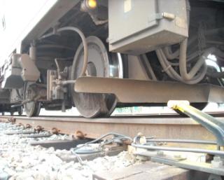
15 MODULE 1: Overview and Safety For electrical switches without hand throw ability, insert a hand crank which will open the crank contacts to switch, removing motor and in some instances indication power. If neither application is available remove power in the signal case by turning off breaker or removing the power fuse to the individual switch/s your are working on. See Video 1.1 Putting Switch into Hand Throw for an illustration on how to put an electrical switch into hand throw ( For electro-pneumatic switches and derails, use the shut off valve to remove pneumatic pressure (air) - unless it is needed for the inspection/maintenance to be performed. For in-pavement electro-hydraulic switches and derails, insert the hand throw lever into the lever box. At this point, the hand throw lever energizes the lever box proximity sensor, which deenergizes the motor and detector circuits. The switch can then be manually operated via the hand throw lever with a single stroke. Figure 1.3 In Pavement Electro-Hydraulic Switch with Red Hand Lever in Place in Lever Box - If it is not possible to remove power but the point will not need to be moved, the point should be secured using either a switch clamp or switch block and spike in order to diminish the chance of getting body parts pinched in the switch. Note that permissions may be required from dispatcher/center to block/clamp and spike the switch. Always follow your authority's procedures. Workbook Not for Distribution: For Consortium Use ONLY 6


16 MODULE 1: Overview and Safety Figure 1.4 Switch Clamp Figure 1.5 Switch Clamp in Use For the switch clamp, clamp the point against the rail as close to the end of the point as possible. If the switch will be out of service for a long period of time, a switch clamp with a lock (Figure 1.4 and Figure 1.5) may be used. As always, follow your authorities procedures. Figure 1.6 Spike Against Closed Point Figure 1.7 Block Wedged Tightly between Open Point and Stock Rail When using the switch block and spike technique, a standard wood wedge will be put in the open point, pushed back until it is tight against the stock rail. A spike will be placed through the tie plate tight against the closed point. Workbook Not for Distribution: For Consortium Use ONLY 7
17 INSPECTION AND MAINTENANCE OF SWITCHES AND DERAILS MODULE 2: Switch and Derail Specific Print Reading Module 2 Outline SWITCH AND DERAIL SPECIFIC PRINT READING 2-1 Overview 2-2 Switch and Derail Specific Nomenclature 2-3 Switch and Derail Specific Symbols 2-4 Switch and Derail Specific Relays 2-5 Switch and Derail Sequence of Operation 2-6 Summary Purpose and Objectives: The purpose of this module is to provide an overview of the specific nomenclature and relays used in railroad switch and derail systems and how they form the operation of railroad switches and derails. Following the completion of this module, the participant should be able to complete the exercises with an accuracy of 70% or greater: List switch and derail specific nomenclature List switch and derail specific relays and describe their functions Using a print, describe the sequence of operation for an M3 single ended switch Demonstrate ability to outline the sequence of operation of a single-ended switch Key Terms Call Clutch Control Circuit Correspondence Crank Cut-out Contact Field Wires Hand Crank Heater Circuit Indication Circuit Indicator Lock Lock Relay Motor Circuit Normal Normal Configuration Overload Coil Overload Relays o Stick Coil o Operation Coil Position Relay Reverse Reverse Configuration Shunting Strip Switch Control Relay (WR) Switch Machine Lock (SML) Switch Related Component Switch Repeater Relay Workbook Not for Distribution: For Consortium Use ONLY 17
18 INSPECTION AND MAINTENANCE OF SWITCHES AND DERAILS MODULE 2: Switch and Derail Specific Print Reading Table 3 Other Switch and Derail Specific Nomenclature (*Source: AREMA volume 4 page 208) Abbreviation Item* AREMA* Your Location Switch operating mechanism or lock valve W Relay, controller or contactor controlling both normal and reverse operations of a switch or an electric switch lock WR Relay, controller or contactor controlling the normal operation of a switch or an electric switch lock NWR Relay, controller or contactor controlling the reverse operation of a switch or an electric switch lock RWR Relay repeating WR WRPR Relay repeating position of switch WPR Relay repeating normal position of switch or normal NWPR position of WPR Relay repeating reverse position of switch or normal RWPR position of WPR Indicator of the positions of a switch WK Switch and derail lock operating mechanism on a switch WL Relay repeating normal position of a switch lock NWLPR Relay repeating normal position of a dual-control lever NJPR Relay repeating reverse position of dual-control lever RJPR Indicator of the normal position of a switch NWK Indicator of the reverse position of a switch RWK Indicator of the block condition in approach to a switch WAK Relay repeating reverse position of a switch lock RWLPR Normal Switch Correspondence Relay NWCR Reverse Switch Correspondence Relay RWCR Spring Switch SS Lock Relay LR Reverse Switch Request Relay RWZR Normal Switch Request Relay NWZR Restore to Normal Request Relay R-NWZR Workbook Not for Distribution: For Consortium Use ONLY 19 Notes
19 INSPECTION AND MAINTENANCE OF SWITCHES AND DERAILS MODULE 2: Switch and Derail Specific Print Reading Figure 2.9 Example Reverse Configuration Control Circuit of an Electric Switch Workbook Not for Distribution: For Consortium Use ONLY 28
20 Module 3 Outline COURSE 202: INSPECTION AND MAINTENANCE OF SWITCHES AND DERAILS MODULE 3: General Inspection & Maintenance of Switches and Derails 3-1 Overview 3-2 General Inspection and Maintenance 3-3 Lubrication 3-4 Inspecting and Maintaining Rods 3-5 Inspecting and Maintaining Circuit Controllers 3-6 Inspecting and Maintaining Ancillary Parts 3-7 Seasonal Inspection and Maintenance 3-8 Testing 3-9 Inspection and Maintenance Cleanup 3-10 Summary GENERAL INSPECTION & MAINTENANCE OF SWITCHES AND DERAILS Purpose and Objectives: The purpose of this module is to provide an overview of the inspection, maintenance and testing that is performed on all types of switches. More specific details for different types of switches will be covered in the following modules. Following the completion of this module, the participant should be able to complete the exercises with an accuracy of 70% or greater: Identify hardware which needs to be tightened Demonstrate ability to tighten appropriate hardware Ensure all locks are in place and secure Identify areas/components which need to be lubricated on a regular PM schedule Inspect and maintain switch layout (where applicable) Describe purpose and components of mechanical locking Inspect and maintain lock rod Inspect and maintain throw rod Inspect and maintain point detector rod Inspect and maintain switch circuit controller Inspect and maintain switch point heaters/snow melters (where applicable) Inspect and maintain moveable point frogs Demonstrate ability to perform point detector test Demonstrate ability to perform obstruction test Demonstrate ability to adjust point tension Inspect and maintain circuit control heaters (where applicable) Demonstrate ability to test electrical indication Workbook Not for Distribution: For Consortium Use ONLY 35


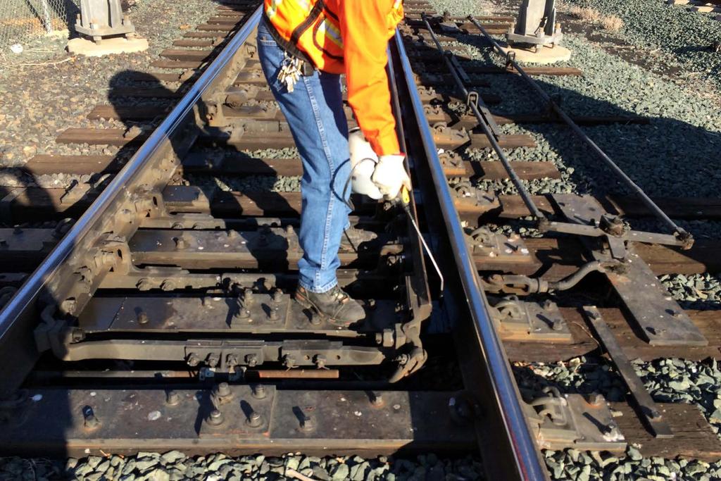
21 MODULE 3: General Inspection & Maintenance of Switches and Derails 3-2 GENERAL INSPECTION AND MAINTENANCE The first step in doing any inspection and maintenance is to perform a sensory inspection. For switches and derails this includes walking the length of the layout, both inside and outside, to make sure that all hardware is in place, clean and secure. Hardware that should be checked include nuts, bolts, ties, points, derails, etc. One visual sign that may indicate that hardware is not secure is the presence of rust around that hardware. Pay special attention looking for items that would inhibit smooth movement of the switch point and/or hang the switch up. The majority of hardware to check are nuts and bolts. These are found on operating rod, track rods, lock rods, point detector rods, yoke and on switch mounting bolts (on all four corners). Hardware to check include: Nuts and bolts Switch Heater Terminations Bonding Ground Wires Switch keeper* also known as Lock Stand Track braces* Plates* Stock Rail Spikes/Screw Spikes* Electro-Hydraulic Difference: do not inspect/maintain the following: Switch Keeper Plates Track Braces Stock Rail Spikes/Screw Spikes Figure 3.1 Switch Layout Highlighting Hardware to Inspect - Courtesy LIRR Workbook Not for Distribution: For Consortium Use ONLY 39


22 MODULE 3: General Inspection & Maintenance of Switches and Derails An operating rod wrench or pry bar is used to make sure that the point or derail is tight against the stock rail. Next, the switch should be thrown. Notice any excessive movement of the tie plates, ties, stock rail or the switch machine itself. Additionally, make sure all appropriate locks are in place and secure. Generally, the locks that should be in place include the keeper lock also known as the throw lock, circuit controller lock,, gear compartment locks, two motor locks and a junction box lock, if equipped. Make sure to tighten any lose hardware and replace any pieces that are missing. Table 7 Generic Sensory Inspection of Switches and Derails Sense Example Problems Sight Debris, dirt, clutter, untamped ballast, rotting, instabilities, rust, worn insulation, lubricant outside the gearbox, proper drainage, hairline damage or distortion to case, cover and/or other structural components, breaks/weak points or any other signs of physical damage. Smell Burning Touch loose points, hardware, etc Hear Grinding, clanging sound, loose or broken parts During this walkthrough, perform a visual inspection of switch rod and gauge plate insulation. Worn/deteriorated insulation will not only disrupt the track circuit but can also affect the integrity/alignment of the switch layout. This may be a problem the day of inspection or in the future if further deterioration occurs. If insulation is worn and/or deteriorating, notify the correct personnel in charge so that it will be replaced as soon as possible. Deteriorating Insulation Insulation is in Good Condition Figure 3.2 Insulation - Courtesy LIRR Workbook Not for Distribution: For Consortium Use ONLY 40
TECHNICAL MANUAL TRAY DRYER
 TECHNICAL MANUAL FOR TRAY DRYER MODEL TD321-3 TRAYDRYER MODEL: TD 321-3 Table of Contents Part 1 - Technical Information * Introduction * Catalogue Cut-sheet and Installation Drawing * Warranty Part 2
Technical Data. Name: ERIKA Automat fully automatic machine to divide and to round dough pieces of the same size
 AUTOMAT MANUAL 1 Technical Data Name: ERIKA Automat fully automatic machine to divide and to round dough pieces of the same size Type Divisions Dough Portions (in ounces) Plate Nos. 3 30 1.0 3.5 #35 4/40A
Preventative Maintenance Tables
 Preventative Maintenance Tables Table of Contents I. Table : Gas Fired Domestic Hot Water Heater II. III. IV. Table : Circulating Pump Table : Convectors Table 4: Grille and Diffusors V. Table 5: Unit
Electronic Circuit Controller
 Union Switch & Signal Inc., an Ansaldo Signal company 1000 Technology Drive, Pittsburgh, PA 15219 645 Russell Street, Batesburg, SC 29006 SM 9020, Field Test Unit (N42252601) for the Electronic Circuit
USER'S MANUAL PGE Single Package Rooftop
 USER'S MANUAL PGE Single Package Rooftop Gas Heating/Electric Cooling Units Sizes 036-150 3 to 12-1/2 Tons NOTE TO INSTALLER: This manual should be left with the equipment owner. WARNING: If the information
XPS-ProDry User s Guide Dryer Base
 XPS-ProDry User s Guide XPS-ProDry User s Guide Dryer Base For Use with Inkjet Imaging Systems Manual Part#: M-3120 Revision: August 2005 XPS-ProDry User s Guide Written by Frank Mauri & John Brand Published
USER MANUAL UN-200V / UN-200VH
 USER MANUAL UN-200V / UN-200VH CONTACT US PHONE/FAX Toll Free: 800.465.1004 Phone: 801.486.1004 Fax: 801.486.1007 ADDRESS LACO Technologies, Inc. 3085 West Directors Row Salt Lake City, UT 84104 WEB www.lacotech.com
SuperKlean Washdown Products
 DURAREEL DR8 & DR8S INSTALLATION AND MAINTENANCE INSTRUCTIONS **DO NOT THROW AWAY AFTER INSTALLATION** **SAVE AND DISPLAY PROMINENTLY WHERE THIS EQUIPMENT IS USED** GENERAL WARNINGS High pressure and hot
BLAST-IT-ALL BUMPER BLASTER
 LARRY HESS AND ASSOCIATES, INC 185 PIPER LANE / SALISBURY, NC 28147 PHONE: 1-800-535-2612 / FAX: 1-704-638-9311 WWW.BLAST-IT-ALL.COM BLAST-IT-ALL BUMPER BLASTER SUCTION BLAST CABINET NOTE: It is the responsibility
MANUAL COVER. To expedite parts ordering or technical questions, please include your Model and Serial Number listed below in all correspondence.
 MANUAL COVER We at Larry Hess & Associates, Inc. would like to take this opportunity to thank you for your patronage. The machine you have purchased has been manufactured and assembled in the USA with
Field Inspection: MART Parts Washer
 Page 1 of 5 Inspection completed by: Date: Company name: Phone: Location: Customer Contact: Job description: Phone: E-mail: Other Contacts: Job description: Phone: E-mail: Is this a service call? [ ] Is
Hakki Pilke Raven spare parts manual
 1 ENGLISH Hakki Pilke Raven spare parts manual Valimotie 1, FI-85800 Haapajärvi, FINLAND Tel. +358 8 772 7300, Fax +358 8 772 732 info@maaselankone.fi, www.maaselankone.fi 2 Table of contents 1 Upper section
Operation & Maintenance Manual
 Operation & Maintenance Manual Brail Fire Curtain m WARNING Improper use of rigging equipment can result in serious injury. Do not operate without proper training and authorization. Not for lifting people.
XC-18. NOTE: *Machine shown without Lift-Up Safety Guard. This guard is included with machine. Machine should not be operated without this guard.
 XC-18 NOTE: *Machine shown without Lift-Up Safety Guard. This guard is included with machine. Machine should not be operated without this guard. EXTREMA MACHINERY COMPANY, INC. PO BOX 1450, ALBANY, LOUISIANA
MAGNETIC ELLIPTICAL TRAINER SF-E3416 USER MANUAL
 MAGNETIC ELLIPTICAL TRAINER SF-E3416 USER MANUAL IMPORTANT: Please read this manual carefully before using the product. Retain owner s manual for future reference. For Customer Service, please contact:
Field Start-Up Sheet Direct Fired Gas Equipment
 Customer: Sales Representative: Model Number: Serial Number: Field Start-Up Sheet Direct Fired Gas Equipment ***Please Print*** INITIAL INSPECTION I. Installer Responsibilities 1. Remote Panel: All interconnecting
IMAGE V. Parts and Service Manual
 IMAGE 0V Section II Parts and Service Manual (88B) CLARKE TECHNOLOGY Image Operator's Manual Page AUTHORIZED PERSONNEL MAINTENANCE To Access Pump Motor. Remove brush housing from machine. See "Brush Motor
SECTION 1-1 SAFETY PRECAUTIONS DOUBLE ARM MIXER CHAPTER 1: SAFETY
 SECTION 1-1 SAFETY PRECAUTIONS Peerless mixers are designed and built to operate as safety as possible. However, if the precautions and procedures explained in this manual are not followed at all times,
Welcome! Today s topic: Small Home Repairs. November 14, 2015
 Welcome! Today s topic: Small Home Repairs November 14, 2015 Small Home Repairs Course Presented by Monique Johnson Environmental Green Solutions, LLC Objective Educate homeowners on basic technical skills
UHIR Series. Horizontal or Vertical Mounting Industrial / Commercial Electric Unit Heater. Owner s Manual
 UHIR Series Horizontal or Vertical Mounting Industrial / Commercial Electric Unit Heater Owner s Manual This manual covers installation, maintenance and repair parts. Read carefully before attempting to
Maintenance 5-1. Good maintenance is essential for cleaning results, and long economical life of the washer.
 Maintenance 5-1 5 Maintenance Purpose This chapter discusses the maintenance of your StingRay Parts Washer. In general, the washer is not maintenance-intensive. A few key items, however, need regular,
PATTERSON FAN MANUAL. Operating, Installation & Parts Manual (OIPM) Patterson Fan Company, Inc Blythewood, SC
 Patterson Fan Company, Inc Blythewood, SC") PATTERSON FAN MANUAL Operating, Installation & Parts Manual (OIPM) Patterson Fan Company, Inc Blythewood, SC 29016 www.pattersonfan.com 800.768.3985 Contents Page Assembly Instructions 3-10 Maintenance
PATTERSON FAN MANUAL Operating, Installation & Parts Manual (OIPM) Patterson Fan Company, Inc Blythewood, SC 29016 www.pattersonfan.com 800.768.3985 Contents Page Assembly Instructions 3-10 Maintenance
Indirect gas-fired air heater
 Indirect gas-fired air heater SERIES HD INSTALLATION AND SERVICE MANUAL MANUFACTURED BY : BROTHERS LIMITED WARNING Improper installation, modification, adjustment or maintenance may cause damage, injury
PRO 2000i LOW LEVEL DEPOSITOR
 DEPOSITORS AND AUTOMATED CAKE PRODUCTION SYSTEMS PRO 2000i LOW LEVEL DEPOSITOR OPERATION AND SPARE PARTS MANUAL Serial No. PR2L- (Please quote this number when ordering spares, and making service calls)
Operator s Manual. Model: TX31 Mini Round Baler. ibexequipment.com IBEX
 Operator s Manual Model: T31 Mini Round Baler 2018-07.1 ibexequipment.com 833-888-IBE Contents 1 Introduction... 1 1.1 Conditions of Use... 1 1.2 Machine Description... 1 1.2.1 Pickup Lift Lever and Lock
ILLUSTRATIONS ARE FOR REFERENCE ONLY AND ARE SUBJECT TO CHANGE WITHOUT NOTICE ITEM P/N DESCRIPTION
 TC-0 TURN PLATE TC-0 TURN PLATE 0 0 0 TC-0-000 TURNTABLE TC-0-00 TURNTABLE, TC-0 TC-0-00 SCREW, M X TC-0-00 COVER, TC-0 TC-0-00 RETAINING PIN TC-0-00 CLAMP TC-0-00 CLAMP SEAT TC-0-0 CLAMP SEAT, TC-0 TC-0-00
2 Installation Instructions For Vari-Fan Ceiling Fans Installation Instructions For Vari-Fan Ceiling Fans 11
 Installation Instructions For Installation Instructions For Vari-Fan Ceiling Fans Vari-Fan Ceiling Fans Installation Instructions For Vari-Fan Ceiling Fans Vari-Fan Ceiling Fans DC powered fans designed
Service Manual Q MODEL DISPENSER Q160/290/300
 Q MODEL DISPENSER Q160/290/300 Service Manual Thank you for selecting a Manitowoc Dispenser, the dependability leader in ice making equipment and related products. With proper care and maintenance, your
DryAire DRYING CABINET
 CONSUMER SERVICES TECHNICAL EDUCATION GROUP PRESENTS L-72 DryAire DRYING CABINET Model LMA1053L JOB AID Part No. 8178202 FORWARD This Whirlpool Job Aid, DryAire Drying Cabinet, (Part No. 8178202), provides
Control Panel For Water Wash Hoods AM2
 Control Panel For Water Wash Hoods AM2 For further information Call: (919) 554-1025 Or Fax: (919)554-1525 Aqua-Matic 117 Franklin Park Ave. Youngsville, NC 27506 TABLE OF CONTENTS AQUA-MATIC LIMITED WARRANTY
PERFECT FIT IN-DASH HEAT/ COOL/ DEFROST PLYMOUTH BELVEDERE
 PERFECT FIT IN-DASH HEAT/ COOL/ DEFROST 1966-67 PLYMOUTH BELVEDERE CONTROL & OPERATING INSTRUCTIONS The controls on your new Perfect Fit system. Offers complete comfort capabilities in virtually every
Hydraulic Crimping Heads and
 Hydraulic Crimping Heads 58422-1 and 2161730-1 Instruction Sheet 408-9535 30 MAY 17 REV D 1. INTRODUCTION Figure 1 This instruction sheet covers application, inspection and maintenance procedures for Crimping
User s Information Manual
 48AJ,AK,AW,AY020-060 Single-Package Rooftop Gas Heating Units with COMFORTLINK Controls and Scroll Compressors User s Information Manual NOTE TO INSTALLER This manual should be left with the equipment
INSTALLATION, OPERATION, AND MAINTENANCE MANUAL
 INSTALLATION, OPERATION, AND MAINTENANCE MANUAL TUBE AXIAL FANS BTA, WTA, HTA, DDA The purpose of this manual is to aid in the proper installation and operation of the fans. These instructions are intended
Power Washer Maintenance
 Power Washer Maintenance Purpose The maintenance of your MART Power Washer. In general, the washer is not maintenance-intensive. A few key items, however, need regular, scheduled care: Use the information
ORIGINAL SPARE PARTS CHD-6330
 ORIGINAL SPARE PARTS CHD-6330 85010075/02 Revision 02/2013 FRAME 1.0 FRAME 1.0 Rif Code Description 1 *4399880 SCREW TE 10x40 2 *4399378 WASHER D.10 (10,5x21x2) 3 *6611330 SUPPORT 4 *7910913 CHUCK 5 *4399288
Patterson Fan Manual. Operating, Installation & Parts Manual (OIPM) Patterson Fan Company, Inc Blythewood, SC
 Patterson Fan Company, Inc Blythewood, SC") Patterson Fan Manual Operating, Installation & Parts Manual (OIPM) Contents Page Assembly Instructions 3-10 Maintenance Instructions 12-14 Trouble Shooting 15 See Other Patterson Manuals: Patterson Wiring
Patterson Fan Manual Operating, Installation & Parts Manual (OIPM) Contents Page Assembly Instructions 3-10 Maintenance Instructions 12-14 Trouble Shooting 15 See Other Patterson Manuals: Patterson Wiring
HEATING AND VENTILATION
 SECTION 14-102.04 14-102.04/ 1 2007OC19 DESCRIPTION The heating, ventilation and air conditioning (HVAC) system is designed to optimize passenger comfort. The system regulates interior vehicle atmosphere,
CABINET PARTS. For Models: ED5SHAXMQ00, ED5SHAMXT00, ED5SHAXMB00 (White) (Biscuit) (Black) REFRIGERATOR. Part No Rev.A
 (Biscuit) (Black) REFRIGERATOR. Part No Rev.A") CABINET PARTS REFRIGERATOR 4 04 Printed In U.S.A. (kdj) 1 Part No. Rev.A LITERATURE PARTS 1 LIT2261135 Energy Guide LIT2255705 Owner s Manual LIT2255380 Service & Wiring Sheet LIT2220407 Modular Icemaker
CABINET PARTS REFRIGERATOR 4 04 Printed In U.S.A. (kdj) 1 Part No. Rev.A LITERATURE PARTS 1 LIT2261135 Energy Guide LIT2255705 Owner s Manual LIT2255380 Service & Wiring Sheet LIT2220407 Modular Icemaker
User s Information Manual
 62DA,DB,DC,DD07-38 Vertical or Horizontal Dedicated 100% Outdoor Air Unit with Optional Gas Heat User s Information Manual NOTE TO INSTALLER This manual should be left with the equipment owner. : If the
PISTON DEPOSITOR TABLE OF CONTENTS
 SAFETY TABLE OF CONTENTS CHAPTER 1. SAFETY 1-1 Safety Precautions...1-3 1-2 Personal Protective Equipment...1-5 1-3 LockOut/TagOut Procedures...1-6 Chart 1-3-1 Piston Depositor Energy Sources...1-6 Example
HEAT/ COOL/ DEFROST FORD THUNDERBIRD
 specializing in AIR CONDITIONING, PARTS AND SYSTEMS for your classic vehicle PERFECT FIT IN-DASH HEAT/ COOL/ DEFROST 1964-66 FORD THUNDERBIRD CONTROL & OPERATING INSTRUCTIONS The controls on your new Perfect
OPERATOR S MANUAL. For BURLY ATTACHMENTS
 OPERATOR S MANUAL For BURLY ATTACHMENTS April 4, 2018 Clod-Buster Topsoil Screener LIMITED WARRANTY Burly Attachments, LLC warrants to the original Purchaser, all products, manufactured by it, to be free
INSTALLATION INSTRUCTIONS
 INSTALLATION INSTRUCTIONS T CLASS TSA Series 6 to 20 Ton AIR CONDITIONERS 6 20 TONS 506147 01 06/11 Supersedes 3/11 Litho U.S.A. RETAIN THESE INSTRUCTIONS FOR FUTURE REFERENCE IMPORTANT The Clean Air Act
INSTALLATION INSTRUCTIONS FOR 6532 SERIES PACKAGE HEAT PUMP
 INSTALLATION INSTRUCTIONS FOR 6532 SERIES PACKAGE HEAT PUMP RV Products A Division of Airxcel, Inc. P.O. Box 4020 Wichita, KS 67204 1976-360 (1-02) PP TABLE OF CONTENTS 1. Warnings......................................................
SECTION 1-1 SAFETY PRECAUTIONS
 SECTION 1-1 SAFETY PRECAUTIONS Rotary Dough Feeders (RDF s) are designed and built to operate as safely as possible. However, if precautions and procedures explained in this manual are not followed at
Vari-Cyclone Ceiling Fans
 Installation Instructions For Vari-Cyclone Ceiling Fans Installation Instructions For Vari-Cyclone Ceiling Fans Vari-Cyclone Ceiling Fans DC powered fans designed to operate on 12 or 24 vdc only! Toll
OPERATIONS AND MAINTENANCE MANUAL FOR THE 8-TON TURF CART ENVIRONMENTAL CONTROL UNIT (ECU) PART NUMBER
 PART NUMBER") OPERATIONS AND MAINTENANCE MANUAL FOR THE 8-TON TURF CART ENVIRONMENTAL CONTROL UNIT (ECU) PART NUMBER 2001927 Prepared by: 860 Douglas Way PO Box 530 Natural Bridge Station, VA 24579 1 1.0 SCOPE: This
OPERATIONS AND MAINTENANCE MANUAL FOR THE 8-TON TURF CART ENVIRONMENTAL CONTROL UNIT (ECU) PART NUMBER 2001927 Prepared by: 860 Douglas Way PO Box 530 Natural Bridge Station, VA 24579 1 1.0 SCOPE: This
WSD-E WHEEL DETECTOR QUICK REFERENCE GUIDE JUNE 2016 DOCUMENT NO. SIG-QG VERSION A
 QUICK REFERENCE GUIDE WSD-E WHEEL DETECTOR JUNE 2016 DOCUMENT NO. SIG-QG-16-01 VERSION A Siemens Industry, Inc. Rail Automation 9568 Archibald Ave., Suite 100, Rancho Cucamonga, California 91730 1-800-793-SAFE
CABINET PARTS. For Models: GS5SHAXNQ02, GS5SHAXNT02, GS5SHAXNB02, GS5SHAXNS02, GS5SHAXNL02 (White) (Biscuit) (Black) (Stainless Steel) (Stainless VCM)
 (Biscuit) (Black) (Stainless Steel) (Stainless VCM)") CABINET PARTS REFRIGERATOR 10 05 Printed In U.S.A. (kdr) 1 Part No. CABINET PARTS 1 Literature Parts 2305895 Energy Guide 2315213 Owner s Manual 2255955 Service & Wiring Sheet 2220407 Modular Icemaker
CABINET PARTS REFRIGERATOR 10 05 Printed In U.S.A. (kdr) 1 Part No. CABINET PARTS 1 Literature Parts 2305895 Energy Guide 2315213 Owner s Manual 2255955 Service & Wiring Sheet 2220407 Modular Icemaker
Full Size Canister Service Manual Riccar Models 1700 / 1800 Power Nozzles RPB-100 / RPB-220 / RPB-224 / RPB-250
 Full Size Canister Service Manual Riccar Models 1700 / 1800 Power Nozzles RPB-100 / RPB-220 / RPB-224 / RPB-250 Table of Contents I. General Full Size Canister Issues...2 A. Full Bag Indicator...2 1. General
last editted by: Yuyang Chen last edited: 3/12/20152:52:00 PM Page 1 of 1
 Name Refill friction stir spot welder Description RPS 100 spot friction welding system Valid from software version V02.21 Manufacturer and Harms & Wende GmbH & Co KG Model Location E3 2118J SOP Creation
MULTIWASH 14 OPERATOR S MANUAL WARNING: OPERATOR MUST READ AND UNDERSTAND THIS MANUAL COMPLETELY BEFORE OPERATING THIS EQUIPMENT.
 MULTIWASH 4 OPERATOR S MANUAL WARNING: OPERATOR MUST READ AND UNDERSTAND THIS MANUAL COMPLETELY BEFORE OPERATING THIS EQUIPMENT. MW4-MAN 8-08 CONTENTS Page Product information.................................
MACHINE GUARDING: PROTECTING YOU FROM HAZARDS
 MACHINE GUARDING: PROTECTING YOU FROM HAZARDS This easy-to-use Leaders Guide is provided to assist in conducting a successful presentation. Featured are: INTRODUCTION: A brief description of the program
rev3 INSTALLATION & OPERATION MANUAL OIL CIRCULATING HEATING SYSTEM MODEL OSM
 216279-000 rev3 INSTALLATION & OPERATION MANUAL OIL CIRCULATING HEATING SYSTEM MODEL OSM IDENTIFYING YOUR SYSTEM IOM216279-000 The HOTSTART heating system is designed to heat fluids for use in marine
MODEL 4246 MIXER-GRINDER
 MODEL 4246 MIXER-GRINDER 4246S STANDARD (5 HP/1 HP) ML-134220 4246HD HEAVY DUTY (7.5 HP/1 HP) ML-134221 701 S. RIDGE AVENUE TROY, OHIO 45374-0001 937 332-3000 www.hobartcorp.com FORM 34850 (Dec. 2002)
MULTIWASH XL OPERATOR S MANUAL & PARTS LIST PFMW18. Save These Instructions
 OPERATOR S MANUAL & PARTS LIST MULTIWASH XL PFMW18 WARNING: OPERATOR MUST READ AND UNDERSTAND THIS MANUAL COMPLETELY BEFORE OPERATING THIS EQUIPMENT. Tacony, Inc., All rights reserved Save These Instructions
Reproduction or other use of this Manual, without the express written consent of Vulcan, is prohibited.
 SERVICE MANUAL ELECTRIC RESTAURANT RANGES E36LC SERIES ML-136624 E36SLC MODEL SHOWN - NOTICE - This Manual is prepared for the use of trained Vulcan Service Technicians and should not be used by those
MODEL PR16 POWER ROTARY
 MODEL PR16 POWER ROTARY OPERATION, PARTS & MAINTENANCE MANUAL 6926 Smithville Hwy. McMinnville, TN 37110 Phone: 931-934-2211 Fax: 931-934-2200 Email info@tennsmith.com www.tennsmith.com Proudly Made in
HEATING AND AIR CONDITIONING
 XJ HEATING AND AIR CONDITIONING 24-1 HEATING AND AIR CONDITIONING TABLE OF CONTENTS page DESCRIPTION AND OPERATION SERVICE WARNINGS AND PRECAUTIONS...1 COMPRESSOR - 2.5L VM DIESEL....3 COMPRESSOR CLUTCH
TECHNICAL GUIDE DESCRIPTION SPLIT-SYSTEM AIR-COOLED CONDENSING UNITS MODELS: HF-07 FEATURES B-0703
 TECHNICAL GUIDE SPLIT-SYSTEM AIR-COOLED CONDENSING UNITS MODELS: HF-07 DESCRIPTION These Sunline 2000 units are completely assembled, piped and wired at the factory to provide one-piece shipment and rigging.
NEMA Applications Guide
 Page 3 NEMA Applications Guide Carbon Monoxide Alarms and Detectors Published by National Electrical Manufacturers Association 1300 North 17 th Street, Suite 1752 Rosslyn, Virginia 22209 www.nema.org Page
Operator s Manual. Linear Asphalt Compactor. Jesse D. Doyle Isaac L. Howard, PhD Mississippi State University. January 2010 CMRC M 10-1 Version 1
 Operator s Manual Linear Asphalt Compactor Mississippi Department of Transportation Jesse D. Doyle Isaac L. Howard, PhD Mississippi State University An Industry, Agency & University Partnership January
SAFETY AND OPERATING MANUAL
 SAFETY AND OPERATING MANUAL 2 General Safety Warnings WARNING: Read all safety warnings and all instructions. Failure to follow the warnings and instructions may result in electric shock, fire and/or serious
PERFECT FIT IN-DASH HEAT/ COOL/ DEFROST 1968 CHEVROLET IMPALA
 specializing in AIR CONDITIONING, PARTS AND SYSTEMS for your classic vehicle PERFECT FIT IN-DASH HEAT/ COOL/ DEFROST 1968 CHEVROLET IMPALA CONTROL & OPERATING INSTRUCTIONS The controls on your new Perfect
INSTALLATION and OPERATION BALL WASHER MODEL NO: BW-022
 Easy Picker Golf Products, Inc. 415 Leonard Blvd. N., Lehigh Acres, FL 33971 PH: 239-368-6600 FAX: 239-369-1579 Service: 800-982-4653 SALES: 800-641-4653 www.easypicker.com salesdept@easypicker.com INSTALLATION
Industrial Sewing Machine TECHNICAL MANUAL SEWING MACHINE HEAD. Electronic Pattern Sewing Machine. Model PLK-G1010 A180E593P03
 Industrial Sewing Machine TECHNICAL MANUAL SEWING MACHINE HEAD Electronic Pattern Sewing Machine Model PLK-G1010 A180E593P03 FOR SAFE USE Before the installation, operation, and inspection for this product,
Service Manual Trash Compactor Models 15XESSEXF A November 2010 Broan-NuTone LLC 926 West State Street Hartford, WI
 Service Manual Trash Compactor Models 15XESSEXF 99044663A November 2010 Broan-NuTone LLC 926 West State Street Hartford, WI 53027 1-800-637-1453 2 Safe Servicing Practices Safe Servicing Practices To avoid
OWNERS MANUAL FOR MEC 300E ATA
 OWNERS MANUAL FOR MEC 300E ATA PLEASE READ AND FULLY UNDERSTAND THE INSTRUCTIONS PRIOR TO SETTING OR TUNING THE MACHINE. CAUTION: ANY MEC CLAY TARGET MACHINE MUST BE IN THE DISARMED STATE WITH THE BATTERY
ICED CAPPUCCINO MACHINE Taylor MODEL: 390
 4.8.6.3 ICED CAPPUCCINO MACHINE Taylor MODEL: 390 LOCATION: Front of House WHEN CLEANED: Daily, Weekly, Monthly, Seasonal TOOLS/SUPPLIES REQUIRED: Salmon Cloth 2 or 3-Compartment Sink Sink Detergent Sanitizer
ENVIRO-PAK. Operation and Maintenance Manual. Manufacturer of
 ENVIRO-PAK H Series Single Chamber Compactor Operation and Maintenance Manual Manufacturer of ENVIRO-PAK SAFESUB WINDCHILLER 800-737-5533 WWW.ENVIRO-PAK.NET SALES@ENVIRO-PAK.NET 4308 West Admiral Doyle
Junior hand dryer. All installation, maintenance and repair tasks must be carried out by qualified technicians.
 Junior hand dryer Safety regulations All installation, maintenance and repair tasks must be carried out by qualified technicians. Mediclinics remembers the importance of: 1. Becoming familiar with the
MODEL 6430T, 6460 & 6460T POTATO PEELER
 MODEL 6430T, 6460 & 6460T POTATO PEELER MODEL ML-137602 6430T ML-19630 6460 ML-137604 6460T ML-104562 6460C ML-137606 6460CT 701 S. RIDGE AVENUE TROY, OHIO 45374-0001 FORM 37005 (Apr. 2006) Installation,
EFFECTIVE: MAY, American Dish Service ADS MODEL: ASQ GLASSWASHER PARTS MANUAL. 900 Blake Street Edwardsville, Kansas (913) /08
 /08") EFFECTIVE: MAY, 2014 American Dish Service ADS MODEL: ASQ GLASSWASHER PARTS MANUAL 900 Blake Street Edwardsville, Kansas 66111 (913)422-3700 05/08 The American Dish Service part numbers contained in this
EFFECTIVE: MAY, 2014 American Dish Service ADS MODEL: ASQ GLASSWASHER PARTS MANUAL 900 Blake Street Edwardsville, Kansas 66111 (913)422-3700 05/08 The American Dish Service part numbers contained in this
Operating and Service Manual
 Operating and Service Manual TR-3-C 900 2000 PACKAGING TECHNOLOGY EN ISO 9001 70 100 M 745 EAM-MOSCA Corp. 675 Jaycee Drive Valmont Ind. Pk. Telephone (570) 459-3426 Fax (570) 455-2442 TR-3-C 1-1 CONTENTS
Smoke Vent with Manual Winch. Installation, Operation and Maintenance
 Smoke Vent with Manual Winch I. Overview Smoke vents are used, upgraded with manual winches, typically installed in theater applications. The winch is used to manually close the smoke vent from a remote
OPERATOR S MANUAL HWH HYDRAULIC SPACEMAKER ROOM EXTENSION SYSTEM FEATURING: DUAL CYLINDER ROOM EXTENSION (WITH RACK SENSING VALVE) HCORPORATION
 HCORPORATION") HCORPORATIONH W R OPERATOR S MANUAL HWH HYDRAULIC SPACEMAKER ROOM EXTENSION SYSTEM FEATURING: DUAL CYLINDER ROOM EXTENSION (WITH RACK SENSING VALVE) WH HCORPORATION HYDRAULIC ROOM EXTENSION R OFF EXTEND
HCORPORATIONH W R OPERATOR S MANUAL HWH HYDRAULIC SPACEMAKER ROOM EXTENSION SYSTEM FEATURING: DUAL CYLINDER ROOM EXTENSION (WITH RACK SENSING VALVE) WH HCORPORATION HYDRAULIC ROOM EXTENSION R OFF EXTEND
Service Manual. Trash Compactor. Models 15SSEXF 15BLEXF A November 2010
 Service Manual Trash Compactor Models 15SSEXF 15BLEXF 99044662A November 2010 Broan-NuTone LLC 926 West State Street Hartford, WI 53027 1-800-637-1453 2 Safe Servicing Practices Safe Servicing Practices
User manual Universal pipe notcher Type: AL100U V/400V
 User manual Universal pipe notcher Type: AL100U-01 230V/400V Page 1 of 26 Table of contents 1. Foreword... 4 1.1. Name of machine... 4 1.2. Warning... 4 1.3. Target group for each chapter... 4 1.4. Symbols...
SEMPEO SQA Unit Code H02H 04 Wiring electrical equipment and circuits
 Overview This standard covers a range of basic competences that you need to wire up electrical equipment and circuits. It will prepare you for entry into the engineering or manufacturing sectors, creating
User s Guide REO-MECH. Industrial Rebar Benders & Cutters
 User s Guide REO-MECH Industrial Rebar Benders & Cutters WARNING: PLEASE READ THIS MANUAL CAREFULLY BEFORE USING THIS MACHINE Machine is not rated and should not be used for commercial rebar production
Exploded View - Model J-7020M/J-7040M Miter Cut-off Saw Base
 22 Exploded View - Model J-7020M/J-7040M Miter Cut-off Saw Base Parts List - Model J-7020M/J-7040M Miter Cut-off Saw Base 1 J-5507591 Base, Machine 1 1-1 5512197 Plug, Drain (3/8in, PT) 2 5507592 Screw,
Pink Magnetic Elliptical Bike
 Pink Magnetic Elliptical Bike Model No. P8300 IMPORTANT! PLEASE READ THIS MANUAL CAREFULLY BEFORE USING THE BIKE. For Customer Service, please contact: support@sunnyhealthfitness.com IMPORTANT SAFETY INFORMATION
CABINET PARTS For Models: MSD2553WEW01, MSD2553WEB01, MSD2553WEM01 (White) (Black) (Stainless Steel)
 (Black) (Stainless Steel)") CABINET PARTS Refrigerator 4 10 Printed In U.S.A. (jdc)(bay) 1 Part No. Rev. A CABINET PARTS 1 Literature Parts W10210296 Energy Guide W10213163 Owner s Manual W10238215 Service & Wiring Sheet 2220407
CABINET PARTS Refrigerator 4 10 Printed In U.S.A. (jdc)(bay) 1 Part No. Rev. A CABINET PARTS 1 Literature Parts W10210296 Energy Guide W10213163 Owner s Manual W10238215 Service & Wiring Sheet 2220407
CABINET PARTS For Models: ASD2522WRS07 (Stainless)
") CABINET PARTS REFRIGERATOR 9 11 Litho In U.S.A. (wam) (psw) 1 Part No. Rev. A CABINET PARTS 1 Literature Parts W10321484 Use & Care Guide W10275776 Service & Wiring Sheet W10234042 Energy Guide 628370
CABINET PARTS REFRIGERATOR 9 11 Litho In U.S.A. (wam) (psw) 1 Part No. Rev. A CABINET PARTS 1 Literature Parts W10321484 Use & Care Guide W10275776 Service & Wiring Sheet W10234042 Energy Guide 628370
Guide To Troubleshooting INEFFICIENT COOLING FANS
 Guide To Troubleshooting INEFFICIENT COOLING FANS TABLE OF CONTENTS Introduction Enclosure Cooling Basics Key Attributes of Enclosure Cooling Symptoms of Poor Enclosure Cooling Typical Cooling Fan Problems
LBX-2000 POWER STRAPPING MACHINE
 LBX-2000 POWER STRAPPING MACHINE Copyright 2008, Signode 439998 9/2008 (EN) CONGRATULATIONS Thank you for purchasing your LBX-2000 Walk-Up Strapping Machine. The LBX- 2000 Strapping Machine was designed
PRESSURE WASHER MODEL NO: JETSTAR 1750 OPERATION & MAINTENANCE INSTRUCTIONS. WARNING Read the instructions before using the machine PART NO:
 WARNING Read the instructions before using the machine PRESSURE WASHER MODEL NO: JETSTAR 1750 PART NO: 7333230 OPERATION & MAINTENANCE INSTRUCTIONS LS0711 INTRODUCTION Thank you for purchasing this CLARKE
Revised March 2015 Fire Alarm Systems Verification. Schedule I(A) Services. *Manditory Site visit required*
 Services. *Manditory Site visit required*") 1.0 Description of Services Required: Revised March 2015 Fire Alarm Systems Verification Schedule I(A) Services *Manditory Site visit required* Perform the annual fire alarm system and sprinkler system
1.0 Description of Services Required: Revised March 2015 Fire Alarm Systems Verification Schedule I(A) Services *Manditory Site visit required* Perform the annual fire alarm system and sprinkler system
HB CDA SERIES WITH TEMPERATURE SETBACK
 HB CDA SERIES WITH TEMPERATURE SETBACK 2013 NOVATEC, Inc. All Rights Reserved Document: HB CDA IM 7-24-2013 NOTES: Please record the following information, which is specific to this piece of equipment,
Minor Home Repairs. November 4, County of Henrico Department of Community Revitalization
 Minor Home Repairs 1 November 4, 2017 County of Henrico Department of Community Revitalization Educate homeowners on basic technical skills that will help the homeowner understand daily operations of different
CABINET PARTS For Models: 7GS2SHEXPQ03, 7GS2SHEXPL03 (White) (Stainless VCM) REFRIGERATOR
 (Stainless VCM) REFRIGERATOR") CABINET PARTS REFRIGERATOR 03 07 Litho In U.S.A. (mat) 1 Part No. Rev A CABINET PARTS 1 Literature Parts 2261383 Use & Care Guide 2255955 Service & Wiring Sheet 2261377 Energy Guide 2220407 Modular Icemaker
CABINET PARTS REFRIGERATOR 03 07 Litho In U.S.A. (mat) 1 Part No. Rev A CABINET PARTS 1 Literature Parts 2261383 Use & Care Guide 2255955 Service & Wiring Sheet 2261377 Energy Guide 2220407 Modular Icemaker
OPERATING AND MAINTENANCE MANUAL FOR ELECTRIC STAINLESS STEEL HEATER FOR DEIONIZED (DI) WATER ELECTRIC HEATER COMPANY BASE MODEL D
 WATER ELECTRIC HEATER COMPANY BASE MODEL D") OPERATING AND MAINTENANCE MANUAL FOR ELECTRIC STAINLESS STEEL HEATER FOR DEIONIZED (DI) WATER ELECTRIC HEATER COMPANY BASE MODEL D HUBBELL ELECTRIC HEATER COMPANY P.O. BOX 288 STRATFORD, CT 06615 PHONE:
OPERATING AND MAINTENANCE MANUAL FOR ELECTRIC STAINLESS STEEL HEATER FOR DEIONIZED (DI) WATER ELECTRIC HEATER COMPANY BASE MODEL D HUBBELL ELECTRIC HEATER COMPANY P.O. BOX 288 STRATFORD, CT 06615 PHONE:
INSTALLATION AND SERVICE MANUAL FOR THE TAC1000-P FAN SERIES (PNEUMATIC CONTROL) TAC1000-H FAN SERIES (HYDRAULIC CONTROL)
 TAC1000-H FAN SERIES (HYDRAULIC CONTROL)") INSTALLATION AND SERVICE MANUAL FOR THE TAC1000-P FAN SERIES (PNEUMATIC CONTROL) TAC1000-H FAN SERIES (HYDRAULIC CONTROL) Publication No. 01553 Revision 8 Printed in Canada 1.1 INTRODUCTION This manual
INSTALLATION AND SERVICE MANUAL FOR THE TAC1000-P FAN SERIES (PNEUMATIC CONTROL) TAC1000-H FAN SERIES (HYDRAULIC CONTROL) Publication No. 01553 Revision 8 Printed in Canada 1.1 INTRODUCTION This manual
DUAL FUNCTION ROWING MACHINE SF-RW5612 USER MANUAL
 DUAL FUNCTION ROWING MACHINE SF-RW5612 USER MANUAL IMPORTANT! Please retain owner s manual for maintenance and adjustment instructions. Your satisfaction is very important to us, PLEASE DO NOT RETURN UNTIL
RHGN-H: COMMERCIAL AIR HANDLER WITH VARIABLE FREQUENCY DRIVE (VFD) NOMINAL 10 TONS R-410A REFRIGERANT 2-STAGE AIR-FLOW
 NOMINAL 10 TONS R-410A REFRIGERANT 2-STAGE AIR-FLOW") INSTALLATION INSTRUCTIONS RHGN-H: COMMERCIAL AIR HANDLER WITH VARIABLE FREQUENCY DRIVE (VFD) NOMINAL 10 TONS R-410A REFRIGERANT 2-STAGE AIR-FLOW 92-106595-01-00 TABLE OF CONTENTS Introduction.......................................
INSTALLATION INSTRUCTIONS RHGN-H: COMMERCIAL AIR HANDLER WITH VARIABLE FREQUENCY DRIVE (VFD) NOMINAL 10 TONS R-410A REFRIGERANT 2-STAGE AIR-FLOW 92-106595-01-00 TABLE OF CONTENTS Introduction.......................................
 www.whitakerbrothers.com The Challenge Machinery Company provides owner's manuals on its products solely as a courtesy to its customers. See the information below before using this manual. These manuals
SERVICE MANUAL VC3ED FULL SIZE ELECTRIC CONVECTION OVEN - NOTICE -
 SERVICE MANUAL VC3ED FULL SIZE ELECTRIC CONVECTION OVEN VC3ED ML-137013 - NOTICE - This Manual is prepared for the use of trained Vulcan Service Technicians and should not be used by those not properly
Equipment Maintenance Checklist
 The Hartford Steam Boiler Inspection and Insurance Co. One State Street P.O. Box 5024 Hartford, CT 06102-5024 Tel: 800-333-4677 Fax: 484-582-1811 Internet: http://www.hsb.com Equipment Maintenance Checklist
PERFECT FIT SERIES IN-DASH HEAT/ COOL/ DEFROST CHEVROLET NOVA
 specializing in AIR CONDITIONING, PARTS AND SYSTEMS for your classic PERFECT FIT SERIES IN-DASH HEAT/ COOL/ DEFROST 1966-67 CHEVROLET NOVA CONTROL & OPERATING INSTRUCTIONS The controls on your new Perfect