Model DewTech390. Model DewTech 390. Chilled Mirror Dew Point Hygrometer. Instruction Manual
|
|
|
- Sherman Lesley Griffith
- 5 years ago
- Views:
Transcription

1 Model DewTech 390 Chilled Mirror Dew Point Hygrometer Instruction Manual 1

2 Safety Information The Model DewTech390 is designed to be connected to hazardous electric voltages ( V) 50/60Hz and protected by a 13amp fused plug to the mains supply socket. The Model DewTech390 must be earthed. Check to establish that all wiring and connections are not damaged. If damage is observed to any electrical wiring or damage to the apparatus they must not be connected to the mains supply but returned to the supplier for rectification. Warnings Risk of electric shock - Do not open any part of the enclosures of the DewTech390 or any electrical apparatus whilst connected to the mains supply. Do not connect the DewTech390 or any electrical apparatus to the mains supply until they are in their permanent positions. Ignoring this safety information can result in severe personal injury and/or mechanical damage to the DewTech390. The product specifications must not be exceeded at anytime as this may cause damage to the Unit or cause risk of damage or fire. Do not connect the DewTech390 to any other device that is not recommended in this manual. If in any doubt - call Edgetech Instruments Inc. Ensure that the DewTech390 does not come into direct contact with water or any other liquids. To avoid the risk of electric shock, risk of damage or fire these safety instructions and guidelines must be followed. Only qualified personnel/technicians should install this instrument to the mains supply and ensure it is safe before use. Safe Isolation Switch off at the mains socket and remove the plugs before any maintenance is carried out by a qualified person. Always test components with an approved voltage meter before handling to ensure it is completely dead. YOU MUST ALSO READ THE SAFETY INFORMATION ON PAGES 16 and 38 2
3 Document Reference: DewTech Issue 01 ETI 24/09/2014 This is a step by step instruction manual to help you successfully set up correctly the Model before DewTech390 use. This manual should be kept with the DewTech390 Model for future reference. You must also observe the safety information on pages 16 and 38 before installation. Please read this manual carefully from the start Edgetech Instruments, Inc. 3
4 Index Introduction 6 Model DewTech390 Functional Description 7 General Overview 7 Chilled Mirror Model S3 7 Cooling Unit RPC 7 Temperature Controller 8 Temperature Controller Factory Default Settings 9 West Instruction (1) 10 West Instruction (2) 11 MIrror Balance 12 Programmable Functions 12 The ABC Cycle 12 Serial Port 12 The Data Output Function 12 The Control Function 12 Analogue Outputs: 12 Alarm Relays: 12 Programmable Functions Continued 13 Isolated 4-20mA Output: 13 Specifications Installation Unpacking 16 Mounting 16 General 16 Temperature Limits 16 Wiring Connections 16 Safe Isolation 16 Sample Connections 17 Sampling Configurations 17 Sampling Configurations Continued 18 Selection Of Components At Low Dew Points 19 Pressure Measurements 19 Sample Flow Rate 19 Information Display Functions 20 Operating the Dew Master 21 Information display in detail 21 Time and Date 21 System Status 21 Main Displays 21 Bar Graph 21 Information display in detail - continued 22 System Status 22 Main Displays 22 Programming the Dew Master 23 Scroll Menu (Using the Arrow Keys) 24 Display Setup 24 Sample Averaging (1-16) 24 Analogue Output 25 ABC Cycle 25 Alarm Relay 1 25 Programming the Alarm Relay 1 Setpoint 25 Locking In the Programming Changes 25 Programming the Serial Port 26 4
5 Serial Output 26 External Device Connection 26 PC or Terminal Setup 26 RS-232 Commands and Parameter Setting 26 General 26 Help Menu 26 Help Menu Table 27 Start an ABC Cycle 27 ABC Enable 27 ABC Start Time 28 ABC Internal 28 ABC Analog Hold 28 ALARM 1 AND (OPTIONAL) ALARM 2 28 Alarm 1 and Alarm 2 Latches 29 Number of Date Samples to Average 29 Analog Output (Low) (High) (Param) 29 Setting the Date 29 Output Interval 29 Poll for Output 30 Manual Heat 30 Manual Cool 30 Time 30 Units (F,C) 30 Status Report 30 DewMaster System Status Report 31 Help Menu Table. 32 Baud Rate 33 RS-232 Output Interval 33 Default Programmable Parameters 34 System Operation Temperature 35 Automatic Mirror Balance Control (ABC) 35 Microprocessor Control 35 Circuit Descriptions 36 Thermoelectric Dewpoint Temperature Control Circuit 36 Sensor PRT Resistance-to-Voltage Converter 36 Automatic Mirror Balance Control Circuits Alarm Set 37 Display 37 Track or Hold Circuit 37 Routine Maintenance 37 Mirror Cleaning Schedule 38 Mirror Cleaning Calibration of PRT 39 Calibration of the PRT amplifier Operating Adjustments 40 Optical Adjustment Procedure 40 Gain Suggested Spares 42 Trouble Shooting Test Points 45 Contact Information 46 5
6 Introduction Thank you for purchasing an Edgetech Instruments DewTech390 We are sure that you will agree that the DewTech390 is easy and friendly to use, reliable and accurate. At Edgetech Instruments Inc. we are committed to customer satisfaction, through continuous Research and Development, Quality and Customer Service. We encourage all our customers for feedback on our products and services, so please feel free to leave any comments or feedback you may wish to leave here at The Part Number DewTech390 stands for Chilled Mirror Hygrometer incorporating a Dew Master Control Panel and a Refrigerant Pre Cooler). Your DewTech390 has the most reliable quality components installed, the instrument has been hand built to your specification by our time served dedicated engineers. The components have undergone rigorous testing to ensure that you get the reliability, peace of mind and confidence you would expect from any Edgetech Instruments Inc products. You will notice that we have abbreviated the description in parts to CMH and/or DM on occasions throughout the manual. Please read the safety instructions carefully and call Edgetech Instruments Inc. Technical department should you be unclear on any point of this manual. Thank you. The Edgetech Instruments Team. 6
7 Model DewTech390 Functional Description General Overview The DewTech390 Instrument is designed to measure gas moisture as low as 90 C dewpoint. It comprises a standard Edgetech Instruments CMH three stage peltier cooled mirror hygrometer which gives a 95 C temperature depression across the peltier battery at 25 C with remote sensor and a fan cooled refrigerant condensing unit together with a temperature controller and associated electronics. Chilled Mirror Model CMH The CMH is available in two major configurations: 1. The CMH is a dewpoint instrument with the addition of pressure measurement to compute moisture concentration values, in ppm(v) as standard. 2. Can display concentrations at atmospheric pressure or an input from a pressure transducer to compensate for pressure variations. To measure low dewpoints, the hot junction of the peltier battery is pre-cooled to 35 C. To achieve this, a refrigerant pre-cooler (RPC) is used. The refrigerant expansion is designed to occur directly at the base of the peltier battery giving optimum and accurate cooling. At higher dewpoints the peltier base temperature is controlled at +20 C. The CMH alarm 1 relay is set to close at < 45 C dewpoint, at which point the peltier base temperature is controlled at 35 C. Using a primary measurement technique, the CMH is ideal for laboratory, scientific, and research applications, and can be equipped with a mirror microscope when used as a calibration standard. Equipped with provisions for self-checking and automatic mirror balancing, the Model CMH can verify its own performance on a timed sequential basis, making it suitable for process control and continuous unattended operation. Cooling Unit - RPC The cooling unit comprises a compressor and fan cooled condensing unit along with expansion and pressure release (return) valves. The refrigerant expansion valve is a mains powered solenoid valve intended for repetitive operation and driven by the Solid State Relay (SSR). Since the compressor and cooling fan run continuously, the situation arises when the expansion valve is off for long periods and the compressor has nothing to pump. This is especially true when running at Set Point 1. When this happens, the timer drives the return valve (which bypasses the expansion valve) and returns refrigerant to the compressor input. The timer is set to operate for 1 second and then break for 30 seconds. 7
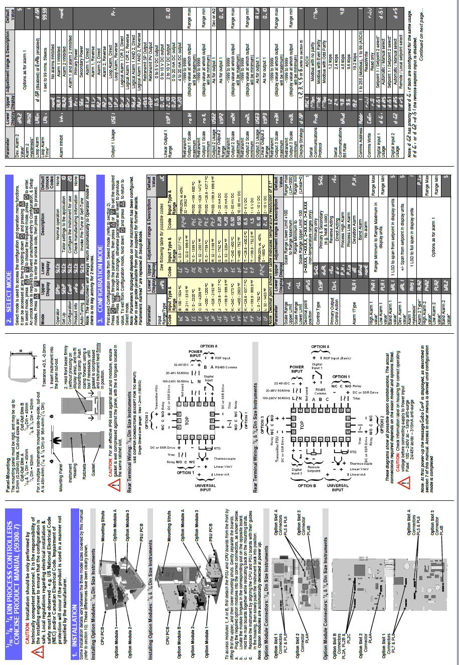
8 Temperature Controller The temperature controller is mounted on the front panel of the auxiliary cooling module. Its operation is fully automatic and does not need to be adjusted. A T type thermocouple is mounted in the wall between the peltier battery and the refrigerant expansion chamber. The thermocouple is read by the temperature controller, which displays the measured temperature in its top display. The refrigerant expansion valve is controlled by the controller output, through the mains rated, solid state relay. Full PID control of the temperature is achieved by PWM control of the output. The PWM period is set to 4 seconds, and the duty cycle range of 15% max. The control set point is +20 C (Set point 1) except when Alarm 1 on the CMH has tripped. In this event, the switch closure of the alarm relay is used to change the set point to 35 C (Set point 2). The instrument s lower display indicates the current set point. A concise product manual for the controller is attached on the next pages, for information and troubleshooting purposes. The tables on the next page give the factory setting for the instrument. 8
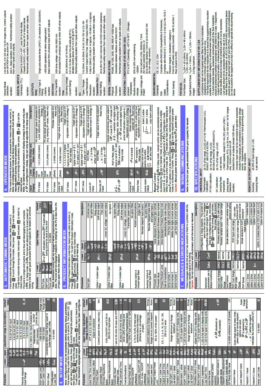
9 Temperature Controller Factory Default Settings 1) Configuration Mode - Unlock Code 20 Note: If any values are changed then the AUTO/MAN key must be pressed after each change to accept the new value. Parameter Value Input Range/Type t.c Scale Range Upper Limit 50.0 Scale Range Lower Limit Control Type SnGL Primary Output Control Action dir Alarm 1Type P_Hi High Alm 1 value 30 Alm 1 Hysteresis 0.1 Alarm 2 Type P_Lo Low Alm 2 value -42 Alm 2 Hysteresis 0.1 Loop Alarm disa Alarm Inhibit none Output 1 Usage Pri Display Strategy 2 Digital Input Usage dis1 Config Lock Code 20 2) Automatic Tuning mode Parameter Value Pre-Tune OFF Self-Tune Tune Lock OFF 0 3) Setup parameters - Unlock Code 10 Note: Any alterations in this menu are automatically changed. Parameter Value Input Filter Time constant 0 Process Variable Offset 0 Primary (Heat) power Read Only (Cannot be set from here) Primary Proportional Band 20 (As set on delivery) Automatic Reset (Integral Time) OFF Rate (Derivative Time) 0.05 Manual Reset (Bias) 0 Setpoint Upper Limit 50.0 Setpoint Lower limit Primary Output Power Limit 20% Output 1 Cycle Time 4 High Alarm 1 value 30 Alarm 1 Hysteresis 0.1 Low Alarm 2 value -42 Alarm 2 Hysteresis 0.1 Auto Pre-tune DISA Auto/manual Control selection EnAb Setpoint ramping DISA SP Ramp Rate Value Blank (Set above 99.99) SP1 Value +25 SP2 Value -35 Setup Lock Code 10 9
10 10
11 11
12 Mirror Balance The Model CMH incorporates an all-electronic, timed, circuit. To correct for changing dry mirror reflectance as a function of contamination, the mirror is heated periodically to a temperature in excess of the dewpoint, and the optical bridge output is balanced electronically for the prevailing reflectance. This heating is accomplished by reversal of the voltage across the thermoelectric cooler in the Sensor. The ABC cycle in the Model CMH can be programmed to start at a specific time and at any interval thereafter. The cycle can also be initiated manually by a pushbutton on the front panel, or via the serial port. This feature increases the time interval between sensor and sample-line cleanings without adversely affecting overall performance. Sensitivity to particularly troublesome impurities, such as salts and other soluble contaminants, is negligible with Alpha Moisture Systems chilled mirror hygrometers, because the compensation circuit and the low thermal mass of the Sensor design permit the use of a heavy condensate layer on the mirror surface without the need for a coalescence pre-cool cycle or other gimmicks to offset the servo instability, drift, and loss of accuracy often encountered in other chilled mirror hygrometers. Programmable Functions The ABC Cycle can be programmed to start at any specified time and repeated at programmed intervals, so that it can be programmed to operate at times when the re-standardisation will cause the least interruption of the sampling process, such as late at night or early in the morning. Serial Port: The serial port is RS-232C compatible and can be used to output data to a terminal, printer, or computer. The Data Output Function sends the date, time, dewpoint and alarm status to any serial device such as a computer, printer or data logger equipped with an RS-232C input. The data can be sent either on command from the external device or automatically at programmed intervals. The Control Function allows the user to start an ABC cycle, initiate maximum cool/heat, and send the status, such as alarm condition, ABC cycle or maximum heat/cool. All commands are listed on a Help menu that can be printed or displayed on a terminal. Analogue Outputs: Two outputs, 0-5 VDC and 4-20 ma, are available simultaneously at the rear terminal connectors. These can be scaled via the front panel keypad or the serial port to correspond to any dewpoint range allowing the user to set the range to suit a particular strip chart recorder or to expand the scale for greater precision. For instance, 0V/4mA could be set to -40 C and 5V/20mA could be set to +10 C. Alarm Relays: Two programmable relays are provided to control valves, enunciators, etc. Each alarm relay can be set independently for high or low, latching or unlatching and at any dewpoint. Alarm 1 is factory configured to operate in conjunction with the refrigerant ancillary cooler, but this function can be disconnected if not required. 12
13 Programmable Functions Continued Isolated 4-20mA Output: An isolated 4-20mA option is available for applications requiring complete isolation between the Model CMH and the 4-20 ma output. As with the standard 4-20mA output, the range matches the 0-5V output set on the Model CMH. Maximum loop resistance is 1000 ohms. 13
14 Specifications Dew/Frost Point Range Accuracy Dew/Frost Point Temperature Sensor -90 C to +20 C Dew point/frost ±0.2 C 3-wire Platinum Resistance Thermometer (PRT) 100 ohms at 0 C, nominal Depression S3 Sensor - 95 C, nominal at 25 C Auxiliary Coolant Sensor Materials Fan cooled, refrigerant condensing unit with temperature controller. Nickel Chromium mirror (Rhodium available), glass, epoxy, isofoam insulation, anodised aluminium sensor body. Depression Rate 1.7 C/second max. above 0 C Repeatability Hysteresis Sample Flow Rate Sample Pressure ±0.01 C None litres/minute 0-5 barg Operating Temperature Control Unit 0 to 50 C Display Keypad LCD graphics backlit display, 0.25-in. (6.35mm) high digits Soft keys for setup and operation: Displayed parameter selection: C/ F toggle: Scroll Menu to change time, date: digital averaging: baud ratio: Manual Auto Balance Cycle initiate: Program Auto Balance Cycle for start time, interval, output Track/Hold: Maximum Heat toggle: Maximum Cool toggle: View/change high and low limits for analog outputs: View/change Alarm parameters, high/low limits, high or low alarms, latched or unlatched relays. 14
15 Outputs Track or Hold Voltage (Standard) Current Outputs (analogue, digital, alarms) can be set to Track or Hold while in Auto Balance or Programming mode. (Factory default is HOLD) 0 to 5 VDC, scalable from 100 to 20 C (-148 to 68 F), 1KΩ minimum impedance Active or Passive (Standard) 4 to 20 ma, scalable from 100 to 20 C (-148 to 68 F), 1KΩ max. loop resistance Isolated (Optional) 4 to 20 ma, scalable from 100 to 20 C (-148 to 68 F), 1KΩ max. loop resistance Digital Mirror Condition (Contaminated) Alarms Auto Balance Control Dimensions Mounting Power Requirements Fuses RS /1200/2400/4800/9600/19CMH Baud N81 25-pin D-subminiature connector (female). Output of time and dew/frost point during operation. Output interval is user programmable. Programming of all keyboard functions, poll dew/frost point, output intervals, on-line Help menu. Rear panel TTL output and front panel LED Two Form C, SPDT alarm relays rated for 3 amps at 24 VDC, 120 VAC Alarm mode (high and low) programmable from keypad or RS-232 Alarm set point programmable from 99.9 to 99.9 C (-148 to 212 F) from keypad or RS-232 port. Alarms can be latched or unlatched. Manual initiation of ABC at any time Automatic ABC, start time and interval programmable from keypad or RS-232 port. Outputs programmable for Track or Hold during ABC. 522mm x 420mm x 604mm (width x height x depth) Free standing bench-top enclosure 100/115/230 VAC, ±10%, Hz, 75 watts maximum 240 VAC Operation 1A, 3AG, 250 VAC, Slo-Blo 120 VAC Operation 2A, 3AG, 250 VAC, Slo-Blo 15
16 Installation Unpacking Remove the Model DewTech390 Dewpoint Hygrometer from its carton and remove any shipping ties, clamps, and packing material (Please Recycle Packaging). Locate and keep the small box containing the Cleaner Kit. Heavy Item The DewTech390 is a heavy instrument weighing approx 40kg. We strongly recommend a minimum of two fit and capable people to lift the item into its permanent position. Consult your Health and Safety officer before lifting. Note: The instrument incorporates a refrigerant compressor. After transport handling the DewTech390 must be allowed to settle before power is applied. Place the instrument in its permanent operating position and allow a minimum of 12 hours before start-up. Mounting General The standard Model DewTech390 is designed for bench top operation. Place the instrument on a clean, flat surface. Ensure there are no obstructions to the free convection of air on the sides and back of the instrument. Temperature Limits Install the instrument in locations where the ambient temperature will be within the range 0 to 50 C. Wiring Connections The instrument requires a power source of 110/240 VAC (50-60Hz). When the Model CMH is received and before attaching it to a power source, examine the printed circuit card behind the window on the AC Power Module on the back of the unit. The card should show 120 or 240, depending on the intended usage. Also, confirm that the corresponding fuse is inserted in the AC Power Module: 2 amp 250V, 3 AG, Slo-Blo for 115 VAC or 1 amp 250V, 3 AG, Slo-Blow for 230 VAC. Safe Isolation Switch off at the mains socket and remove the plugs before any maintenance is carried out by a qualified person. Always test components with an approved voltage meter before handling to ensure it is completely dead. 16
17 Sample Connections A basic requirement of accurate dewpoint measurements is the proper design of the gas sampling system. In order that the Model CMH measures the actual moisture content of the gas, it is essential that the sampling components neither contribute to, nor absorb moisture from the gas. Also, the sampling components must not alter the pressure or temperature parameters of the gas such that they would affect the moisture content of the sample. When dewpoint measurements are made, it is essential that the temperature of sampling components is not allowed to drop below the dewpoint temperature of the sample. This prevents condensation from occurring within the line, causing an in-correct measurement. In general, the most common problem areas that affect the moisture of a sampled gas are: 1. Length of process line and sample line. 2. Leaks in the process line and sample line. 3. Adsorption or absorption of moisture in the process and sample lines due to the materials of construction. 4. Excessive elbows, tees, valves, or other fittings used in the sample lines. 5. Back diffusion of moisture, even into a pressurized system, particularly at low dewpoints. 6. Condensation within the process line and sample line at high dewpoints. 7. Diffusion through the sampling materials. 8. Construct the shortest and safest possible route to source. The procedures and parts recommended in this manual should be used only as a guide in selecting and designing sampling systems. If your application is of a special nature, call Edgetech Instruments for assistance in selecting sampling systems and components as we specialise in this area also. Sampling Configurations A suggested sampling system for use with the Model CMH Dewpoint Hygrometer is shown in Figure 2-1 on the next page. A sample of the gas is brought to the hygrometer location from tapping into the process line, either by venting to atmosphere, using a suitable vacuum pump or by returning the sample to a lower pressure point in the system. The flow rate through the sample line should be sufficient to ensure continuous flushing of the lines in order to provide fast response times. Usually, a flow rate of 0.25 to 2.0 lt/min in a ¼ in. OD. line is adequate. This must be adjusted, however, to suit the length of the line, the level of absolute moisture content of the sample and the desired response time of the sample system. 17
18 Sampling Configurations Continued A bypass line may be used to increase the sample velocity and improve the overall response time. It is necessary that the main sample line be equipped with a valve for adjusting the sample flow rate. The hygrometer s gas sample is obtained from the pressure drop across the bypass as shown in Figure 2-1 below. It is desirable to provide the hygrometer input with a filter, especially if the gas sample contains particulate contaminants. A sintered stainless steel filter is normally suitable Available from Edgetech Instruments. The filter will form a hygroscopic element that will contribute some lag to the sample system. In the design of hygrometer sample systems, minimise the number of components, such as valves, tees, and filters, upstream of the Sensor. Care should always be exercised when incorporating valves into a sample system to consider the influence of any pressure drop or back pressure on the measured value. NOTES Excessively high sample flow rates may cause a loss in the depression capability and unstable operation of the system. Savings can be obtained by recognizing that the sample exhaust lines and related components need not be of as high a quality and as non-hygroscopic as those upstream of the hygrometer. The gas to be sampled can be presented to the CMH using 1/4" OD tube and fitting on the front panel of the instrument. A sample shut-off valve may be used on the input side of the Sensor to extract the sample. Such a valve is especially useful when working with samples at high pressures and when opening the Sensor for periodic mirror cleaning. 18
19 Selection of Components At Low Dew Points Rubber, neoprene, tygon and most plastic tubing are unsuitable for use in hygrometer systems as sample lines from the sample point to the Sensor. Non-hygroscopic tubing, such as stainless steel, Teflon, or KEL- F with a minimum of joints and fittings is recommended. The actual selection of the sample line material should be based on the degree of permanency of the installation, and the type of fittings and connections to be used. Generally, 316 stainless steel is preferred. On stainless steel lines, either swage or flare-type fittings can be used. Leaks in the sampling system must be avoided, since leakage of ambient air into the sampling system will seriously offset the readings obtained. Pressure Measurements The dewpoint temperature of a gas is a measure of the absolute moisture content of the gas, at a given pressure, regardless of the temperature of the gas. Most conversion tables for dewpoint (or frost point) to concentration (ppm, etc.) are made at atmospheric pressure. If accurate absolute moisture content measurements are to be converted to atmospheric pressure reference values, therefore, the pressure must be known. If dewpoints are to be measured at sample operating pressures other than atmospheric, the hygrometer Sensor should be fitted with an appropriate pressure gauge Sample Flow Rate When setting sample flow rates at other than atmospheric pressure, or when gases other than air are involved, use Figures 2-3 and 2-4 to convert the indicated sample flow rate reading to the actual flow rate. Figure 2-3 gives the actual flow rate of air at pressures other than 1 atmosphere. For example, the actual flow rate of air at 30 psia is 3.3 SCFH when the sample flow rate reading is 2.3 SCFH. Figure 2-4 gives the actual flow rate of six different gases. The actual flow rate of helium, for example, when the sample flow rate indicates 1.2 SCFH is 3.3 SCFH (at 1 atmosphere). When gas pressures other than 2 atmosphere are used, use Figure 2-3 to convert the actual flow rate reading obtained from Figure 2-4 to the true flow rate. Using 30 psia, rather than 1 atmosphere in the helium gas example above, apply the 3.3 SCFH actual flow rate obtained from Figure 2-3 as the Flow Gauge Reading on Figure 2-4, and read 4.8 SCFH as the actual flow rate of helium at 30 psia. 19

20 Information Display Functions The Information Display Information Displayed THE LARGE LCD Display mounted on the Front Panel provides the user with all the information necessary to properly operate the DM. It can be used as the primary interface with the instrument, showing status of all parameters and allowing settings to be easily programmed by using the Keypad. NOTES: 1. The RS-232 Serial Port, along with a computer or terminal may also be remotely used for programming the DM. 2. All programming is in non-volatile memory, so that it is retained when power is off. 3. The real time clock continues to run when power is off, maintaining the correct Time and Date information. THE TOP ROW: DATE TIME CONTROL LOOP STATUS The current date The current time Shows Chilled Mirror Control Loop status CENTER ROW (MAIN DISPLAY): DEW POINT AIR TEMPERATURE RELATIVE HUMIDITY The actual measured Dew Point The actual measured Air Temperature The calculated Percent RH NOTES: 1. The three displays may be used to show any available parameter. 2. Temperature and Humidity information may be displayed in any desired sequence. BOTTOM ROW: BAR GRAPH DISPLAY: The Bar Graph displays an actual picture of the dew layer on the chilled mirror surface. The right hand vertical bar indicates the mirror itself, and the white bars show the actual dew layer. The layer can be seen to vary in thickness as the control loop brings the mirror into control at the dew point. Then, a thin layer of dew is maintained on the surface as the mirror temperature tracks the dew point temperature. 20
21 Operating the Dew Master In order to operate this instrument, it is assumed that you have read the INSTALLATION section of this manual, and preliminary tasks have been done. These include: 1. The instrument has been connected to a proper AC power source. 2. If desired, the Analog Outputs, Alarm Relays, and/or Serial Digital (RS-232) Output has been wired. 3. A dew point sensor sampling system, if needed, has been installed. Note: For dry gases, allow sufficient time for the sampling system to dry out (outgas) before taking measurements. If moisture content is only a few parts-per-million, it may be advisable to dry it out overnight. If you have not checked these points, the INSTALLATION chapter should be reviewed before proceeding. The Digital Display will: 1. Light up 2. Briefly indicates DEWMASTER by EDGETECH 3. Go into the normal display mode Information display in detail Time and Date Real time information is displayed in the upper left corner of the main Information Display window. This is programmable via the keypad. It is in non-volatile memory with battery backup, so that the information will remain correct when instrument power is shut off and later turned on again. System Status The status of the DewMaster control systems may be seen in the upper right corner of the Display. When first turned on, it may read HEAT or STARTUP. At other times, it may read MAX HEAT, or ABC: HEAT, or ABC: STABLE, or SEEKING DP. After several minutes, the Display will read SERVOLOCK. This is the normal operating condition, which indicates that the system is tracking the Dew Point. Do not take measurements until the SERVOLOCK indication appears. Main Displays Across the centre of the Information Display window are the three primary displays. They may be programmed to read any measurable parameter. For example, you may wish to display Dew Point, Gas Temperature, and Pressure (with optional pressure sensor) inside your process. In addition, the sequence of these displays is independently programmable. Bar Graph Horizontally across the bottom of the Information Display window is the Dew Layer Bar Graph. The vertical bar on the far right of the graph indicates the actual chilled mirror within the dew point sensor. The white boxes to the left of the mirror bar indicate the thin dew layer maintained on the mirror while tracking the dew point. In other words, the bars provide a magnified picture of the mirror condition during sensor operation. Generally, the dew layer indication will take up approximately 2/3 of the bar graph. 21
22 Information display in detail Continued Real time information is displayed in the upper left corner of the main Information Display window. This is programmable via the keypad. It is in non-volatile memory with battery backup, so that the information will remain correct when instrument power is shut off and later turned on again. System Status The status of the DewMaster control systems can be seen in the upper right corner of the Display. When first turned on, it will read HEAT. At other times, it may read MAX HEAT, or ABC: HEAT, or ABC: STABLE, or SEEKING DP. After several minutes, the Display will read SERVOLOCK. This is the normal operating condition, which indicates that the system is tracking the Dew Point. Do not take measurements until the SERVOLOCK indication appears. Main Displays Across the centre of the Information Display window are the three primary displays. They may be programmed to read any measurable parameter. For example, you may wish to display Dew Point, Gas Temperature, and Pressure (with optional pressure sensor) inside your process. In addition, the sequence of these displays is independently programmable. 22

23 Programming the Dew Master Keypad Operation The DM front panel keypad in Table 3-1 has six soft keys that support the user set up and operation. The label for each key, and its function are described below. Table 3-1. Identification of keys on front panel keypad. Key C/F Function Toggles the displayed parameters, internal parameters and RS-232 output between degrees Fahrenheit and Centigrade. Thus it is important to choose operation in C or F before any other set-up activity. Alarm values and output values are converted from Fahrenheit to Centigrade when the C/F soft key is pressed. The analog output level does not change when C/F is toggled, because ranges are converted. MABC HEAT Starts the Manual ABC cycle. If the DM is already in an ABC cycle, this key cancels the ABC cycle. Turns on/off MAX HEAT. Once this key is pressed, the sensor is kept in MAX HEAT until the MAX HEAT soft key is pressed again. In the MAX HEAT mode, SERVOLOCK is bypassed and the mirror is heated. The upper right section of the LCD flashes MAN MAX HEAT, and the RS-232 output indicates MAX HEAT. During an ABC cycle, MAX HEAT (MAX COOL) does not function. NOTE: Turning on MAX HEAT turns off MAX COOL and vice versa. Both cannot be activated simultaneously. COOL ENT ESC Turns on/off MAX COOL. The sensor is kept in MAX COOL until the MAX COOL soft key is pressed again. The upper right portion of the LCD flashes MAN MAX COOL. Enter to the SCROLL MENU. Exit from the SCROLL MENU. 23

24 Scroll Menu (Using the Arrow Keys) The SCROLL MENU facilitates access to DISPLAY Setup, ANALOG Setup, ALARM Setup, ABC Setup, and SERIAL Setup. In the SCROLL MENU, use the UP, DOWN, LEFT and RIGHT arrows to make your selection and then press the ENT key. The selected function will flash on and off and can now be set to the desired value using the keypad. Pressing the ENT key will stop the flashing and another function can be selected. Once all values have been set press the ESC key. The user will be prompted to accept all changes into non-volatile memory by pressing ENT, or reject them by pressing ESC. Either choice will return to the main DISPLAY. When entered in the SCROLL MENU, Note that lack of activity on the keypad for 30 seconds will cause an exit to the main DISPLAY and no changes will be saved. Display Setup Parameters to be viewed on the main DISPLAY: Left, Centre, or Right, can be set in any order. In the SCROLL MENU enter a display box : L, C, or R, and use the up, down arrows to choose a parameter (or select none). Then press the ENT key. Programming the Current Date Sample Averaging (1-16) With Average set to 1, as each determination is made, it is shown on the display. With the Average set to 2, the two most recent determinations are added together and divided by 2, then displayed. With Average set to 16, the 16 most recent determinations are averaged together for display. If Average is set to 1, the fastest dynamic response is achieved. However, if there is some noise or artefact, it will be displayed. If Average is set to 16, since one determinations are made per second, the most recent 16 seconds of data is averaged to provide each displayed value. If there is some random noise or small but irrelevant changes in dew point, setting Average to 16 will smooth out unwanted or irrelevant changes. This can help avoid false alarms. 24
 is also scaled by selecting the low (LO) and high (HI) range. The output is factory set at 0-5 VDC. 4-20 ma requires a field modification.")
 Range ABC Cycle The Automatic Balance Cycle (ABC) can be initiated manually at any time, or started at any specified time of day (ABC START), and repeated at regular")

25 Analogue Output Analog Output 1 is located on the rear panel. The SCROLL MENU is used to assign parameters to the analog output channel. The analog output (OUT1) is also scaled by selecting the low (LO) and high (HI) range. The output is factory set at 0-5 VDC ma requires a field modification. To change it, see Modifying the Analog Output in the Maintenance section. Setting the Analog Output 3 (RH) Range ABC Cycle The Automatic Balance Cycle (ABC) can be initiated manually at any time, or started at any specified time of day (ABC START), and repeated at regular intervals (ABC INTERVAL). The analog output can be programmed to track or HOLD the parameters during an ABC cycle and the alarm is automatically disabled. To program a periodic ABC from the SCROLL MENU the START function must be ON. If ABC HOLD is ON, the analog and serial outputs will be held at the values just prior to initiating the ABC cycle. The Display will contain the message ABC HOLD. The hold will be released when the ABC cycle is complete and the instrument has stabilized back on the dew point. Alarm Relay 1 From the SCROLL MENU, the relay can be programmed to be off (OFF), to activate when the low limit is reached (LOW), or to activate when the high limit is reached (HIGH). Programming the Alarm Relay 1 Set point Locking In the Programming Changes 25
26 Programming the Serial Port Serial Output The RS232-C serial port is located on the rear panel. To access serial communication it is necessary to have the Serial Enable on (ON), from the SCROLL MENU, and also to select the appropriate baud rate. The DewMaster serial port can be used to operate the unit, program parameters, or output data to a printer, data terminal, or personal computer. For bi-directional communications (such as with a PC or Terminal), a communication or terminal emulation software package is needed on the PC. There are many inexpensive communication programs readily available. Two such programs are HyperTerminal in Windows or PROCOMM PLUS by Quarterdeck/Datastorm Corp. External Device Connection Connect an RS-232 cable between the DewMaster 9-pin female D-Type connector and the RS-232 serial port of the external device. All hardware handshaking lines are available at the connector; however a 3-wire XON/XOFF cable is all that is normally required. The serial port is wired as a DTE device (Data Terminal Equipment); i.e., Transmit (TXD) is pin 2 and Receive (RXD) is pin 3. Circuit common is pin 5. For connection to a DCE device (Data Communications Equipment) such as a PC, a direct pin-to-pin cable can be used. For connection to another DTE device such as a printer, a null modem adapter is required. PC or Terminal Setup Set the DewMaster to the preferred baud rate via the SCROLL MENU. The available baud rates are 19.2K, 9600, 4800, 2400, and For optimum performance, the baud rate should be set to the highest rate that the connected device can accommodate reliably. Set up the PC s communication program for a baud rate to match the DewMaster. The protocol should be 8 data bits, 1 stop bit, and no parity (N81). RS-232 Commands and Parameter Setting General Several of the setup and operating features of the DewMaster are available via the serial port. Commands can be upper or lower case. When any key is pressed, the DewMaster will respond with Input: and the key that was pressed key. If the command is a single key command, pressing ENTER will initiate the command. For a two key command, press the second letter and then the ENTER key to initiate the command. Help Menu Once communication has been established, the available commands can be viewed by accessing the HELP menu. Type the letter H. The display will reply with INPUT: H. Press ENTER and the HELP menu as shown in Table 12-1 will be displayed on the screen. 26
27 Help Menu Table Commands Start a Manual ABC Cycle ABC enable toggle ABC Start Time (HH:MM) Analog Hold Toggle (on/off) ABC Interval (HH:MM) Alarm 1 (> or <) (Deg) (param) Alarm 2 (> or <) (Deg) (param) Analog 1 Output (Min) (Max) (param) Analog 2 Output (Min) (Max) (param) Analog 3 Output (Min) (Max) (param) Average (Number of Data Points) Enter New Date (MM/DD/YY) Latch Alarm1 Toggle ON/OFF Latch Alarm2 Toggle ON/OFF Max Heat Toggle ON/OFF Max Cool Toggle ON/OFF Output Interval RS232 (Secs) Poll for Parameters Display a Status Report Enter New Time (HH:MM:SS) Temperature Units (F, C) Examples (Max Entries Shown) AB <CR> AE <CR> AS <CR> 23:59 <CR> AH <CR> AI <CR> 23:59 <CR> AL1 <CR> > <CR> AL2 <CR> < <CR> AO1 <CR> <CR> AO2 <CR> <CR> AO3 <CR> <CR> AV <CR> 16 <CR> D <CR> 12/31/99 <CR> L1 <CR> L2 <CR> MH <CR> MC <CR> O <CR> 3600 <CR> P <CR> ST <CR> T <CR> 23:59:59 <CR> U <CR> C <CR> Press ENTER to continue.. Notes: When a param (parameter) entry is required, each parameter has a numeric value as follows: DP (Dew Point) = 1; AT (Ambient Temperature) = 2; RH (Relative Humidity) = 3; PPMV = 4; Gr/lb = 5; PSIA = 6; PSIG = 7 and Wet Bulb = 8. Whenever a setting is changed via the serial port, the serial output times are recalculated. Input characters are not case sensitive. Start an ABC Cycle This command initiates an ABC cycle at any time. The cycle is the same as a programmed ABC cycle. Type the letters AB and press the ENTER key. ABC Enable Type AE and then ENTER to alternately enable or disable the timed ABC function. The start time and interval settings will not be changed. NOTE: Two digits must be used for each entry field. 27
28 ABC Start Time Type the letters AS and press the ENTER key. Enter the time Hours: Minutes in 24 hr. format, and press the ENTER key. Examples: 02:00, is 2:00 AM: 14:30 is 2:30 PM. ABC Internal Type the letters AI and press the ENTER key. Type the time in Hours:Minutes and press the ENTER key. Example: If the ABC Start Time is 08:00 o clock in the morning and the ABC Interval is 02:00, the first ABC cycle for the day would occur at 8:00 AM and every two hours thereafter. ABC Analog Hold Typing the letters AH will toggle the ABC Hold feature on or off. If ABC Hold is on, the analog and serial outputs will be held at the values just prior to initiating the ABC Cycle. The serial output will contain the message ABC Hold. The hold will be released when the ABC Cycle is complete and the instrument has stabilized back on the dew point. ALARM 1 AND (OPTIONAL) ALARM 2 The alarm relays can be set to operate at predetermined parameter limits. Each relay can be set as a high or low set point by use of the greater than > and less than < symbols. Each relay can also be independently set to latch when the preset limit is exceeded. In the latch mode, the alarm will remain active even if the alarm condition returns to normal. To reset a latched alarm relay, press the SETUP key twice from the main screen. If the latch mode is not set, the relays will deactivate when the alarm condition is corrected. The front panel alarm indicators will flash to alert the operator of an alarm that has occurred. To enter or change the alarm limits, type the letters AL1 for alarm 1 or AL2 for alarm 2 and press ENTER. Enter the set point beginning with the > or < symbol followed by a space and the sign and value of the alarm limit, and the parameter number of the variable. When completed, press the ENTER key. Examples: > sets relay number one to activate at a level greater than degrees dew point (param 1). < sets relay number two to activate if RH (param 3) falls below 25%. 28
29 Alarm 1 and Alarm 2 Latches The alarms can be set to latch on an alarm condition by typing "L1" for alarm 1 or "L2" for alarm 2. A latched alarm will not reset itself when the alarm condition is resolved but requires operator intervention to reset. The L1 and L2 commands toggle the latch on or off. To reset a latched alarm, press the SETUP key twice. Number of Date Samples to Average This command sets the number of data samples to average. Data is sampled once per second. Therefore, a number of 4 would display a rolling average for the last 4 seconds. The limits are 1 to 16 samples. Type the letters AV and press the ENTER key. The DewMaster will respond with Enter SETTING =. Type the two-digit value and press the ENTER key. Analog Output (Low) (High) (Param) This function sets the 0-5 volt or 4-20 ma (analog) lower and upper output ranges and the parameter for each of three output channels. The instrument range is 100 to +100 C (-148 to +212 F). A plus (+) sign is not needed for positive temperature entries, but a minus (-) sign is necessary. Type the letters AO1 for channel one, AO2 for channel two, or AO3 for channel three, and press the ENTER key. Enter the limits with a minus sign first (if negative), then the lower limit, a space, the positive or negative upper limit, a space, and the parameter number. Press the ENTER key to record these values. Example: Entering sets a low value of -33, a high value of +45, and a parameter of Ambient Temperature (2). The units, C or F, will be whichever is active at the time of the setting. If the units are changed later, all affected parameters will be set to the new units. Setting the Date Type the letter D and then press ENTER. The DATE format is: MONTH/DAY/YEAR 01/01/00 = January 1, /31/99 = December 31, 1999 NOTE: Two digits must be used for each entry field and separated by a backslash character. Output Interval This is the interval in seconds between automatic data output transmissions of the serial data output. The time range is from 0 to 3600 seconds. Type the letter O and press the ENTER key. Enter the desired interval in seconds and press ENTER. 29
30 Poll for Output This command requests the DewMaster to send serial data at any time and is independent of the automatic interval. Type the letter P and press the ENTER key. Manual Heat This command toggles the Sensor s heater on or off. It can be initiated at any time and can be used to clear excessive moisture from the mirror in flooding situations. Type the letters MH and press the ENTER key. The DewMaster will display a flashing MAN MAX HEAT and the temperature will rise. To turn off the MANUAL HEAT mode, enter MH again. Manual Cool This command toggles the Sensor s cooler on or off. It can be used to test the maximum depression of the Sensor. Type the letters MC and press the ENTER key. The DewMaster will display a flashing MAN MAX COOL and the temperature will decrease. To turn off the MANUAL COOL mode, enter MC again. NOTE: After an extended period of time in the cool mode, excess moisture or frost will form on the mirror. It may be necessary to Manually Heat the mirror to shorten the drying time. Time Type the letter T and press ENTER. The time format is: Hours:Minutes:Seconds. Hours is expressed in 24-hour military time. Enter the desired time with colon delimiters: Examples: 00:00:00 = 12 midnight 23:59:59 = 11:59:59 pm Units (F,C) The DewMaster can display temperature in either Degrees C or Degrees F. The display and RS-232 data will reflect the selection. Type the letter U and press ENTER. Type C or F and press ENTER. Status Report This command gives the user a report of all of the current settings. To get a status report, do the following. Type the letters ST. The display will show: Input: ST Press the ENTER key. The following sample status report will display. 30
31 DewMaster System Status Report ABC data: State StartTime Interval Hold ENABLED 0:00:00 2:00 OFF ALARM data: # Item Type Value Latch State 1 DP HIGH 0.00 C ON READY 2 AT LOW C OFF ACTIVATED ANALOG data: # Item Low High 1 DP C C 2 DP C C 3 RH 25 % 75 % DISPLAY data: Left Middle Right Average DP PPMV GR 4 SERIAL data: Baud Interval State :00 ON Press ENTER to continue or ESC to return to normal operation. 31
32 Help Menu Table. Options Example (Max Entries Shown) Display the HELP Menu H <CR> Enter New Time (HH:MM:SS) T <CR> 23:59:59 Enter New Date (MM:DD:YY) D <CR> 12:31:99 Temperature Unit (F,C) U <CR> C <CR> ABC Start Time (HH:MM) AS <CR> 23:59 <CR> ABC Interval (HH:MM) AI <CR> 23:59 <CR> Alarm 1 (>,<) (+) (Deg) A1 <CR> < <CR> Alarm 2 (>,<) (+) (Deg) A1 <CR> < <CR> Analog Output (min) (Max) A0 <CR> <CR> Baud Rate (Baud) B <CR> <CR> Output Interval RS-232 (Sec Gap) O <CR> 3600 <CR> Poll for Dew Point P <CR> Start a Manual ABC Cycle AB <CR> Average (Number of Data Points) AV <CR> 16 <CR> Max Heat Toggle ON/OFF MH <CR> Max Cool Toggle ON/OFF MC <CR> Latch Alarm1 Toggle ON/OFF Latch Alarm2 Toggle ON/OFF L1 L2 32
33 Baud Rate The available baud rates in the CMH are: 19200, 9600, 4800, 2400, 1200, or 300 NOTE: Both the Model CMH and the computer must be set to the same baud rate for communication to take place. If the unit is not communicating properly, check the CMH baud rate setting via the front panel and set the communications software to match the CMH. Also verify that the data format is correct (i.e., Data Bits = 8, Stop Bits = 1, Parity Bit = N). RS-232 Output Interval This is the interval in seconds between automatic data output transmissions of the RS-232 data output. The time range is from 0 to seconds. NOTE: An entry of zero will stop the output of RS-232 data. Press the ENTER key on the computer keyboard. The Enter Command (H for Help): prompt is displayed. Type the letter O and press the ENTER key. Enter the desired interval in seconds and press ENTER. 33
34 Default Programmable Parameters If a fault is detected in the parameter memory, or if the non-volatile memory chip is replaced, the instrument will replace all of the user entered parameters with the default parameters listed in Table 3-5. Table 3-5. Default Programmable Parameters. System Operation Main Control Loop (General Description) Function Default Parameters ABC ST (HOURS MINUTES) ABC INT (HOURS MINUTES) OUT HIGH +60 DEGREES C OUT LOW -40 DEGREES C ALARM 1 >+50.0 DEGREES C ALARM 2 >+50.0 DEGREES C AVE 01 BAUD 2400 OUT INT 60 34
35 System Operation Continued The Model DewTech390 Dewpoint Hygrometer accurately measures the dewpoint of a gas by cooling a mirrored surface, over which the gas flows until a layer of dew forms on the surface. When the mirror is dry (no dew/frost), amplifier A1 outputs a positive voltage and A2 a positive current into the peltier device to cool the mirror surface. As dew forms on the mirrored surface the light reflectance is decreased, resulting in reduction in voltage from amplifier A1 (possibly becoming negative) causing a reversal of current to the peltier device and the mirror surface to heat. The surface of the mirror is maintained at a temperature to control a uniform layer of dew/frost. That temperature is the dewpoint. Temperature The PRT is a component in a bridge, the output of which, proportional to the temperature of the mirror surface, is amplified by A3 and converted into a digital value, approximately once per second, which is used for display of the dewpoint temperature, analogue output (via a digital-to-analogue converter), monitoring of alarm levels, and RS-232 digital outputs. Automatic Mirror Balance Control (ABC) At programmable intervals, the Model CMH can be forced into an Automatic Balance Control (ABC) cycle to compensate for any build-up of contaminants on the mirror surface, which may change the optical balance of the system. When an ABC is begun, the control loop is interrupted, the mirror is heated thus evaporating the dew, and the new balance point is found that compensates for contaminants that may have accumulated and caused a change in the reflectance of the mirror. The control loop is then reconnected, and, after some time, normal control operation is re-established. Microprocessor Control All timing functions, such as time and frequency of ABC cycles, parameter settings, such as alarm levels, and outputs, both analogue and RS-232, are microprocessor controlled. All parameters can be viewed and/or changed via both the front panel keypad and the RS-232 port. The keyboard menu system is arranged for ease of use. All functions can be accessed by no more than four key presses, some by two. When a key is pressed, the microprocessor stops its normal routine of temperature measurement to service the user. Normal operation is resumed when the task is completed, or when about 10 seconds passes without a key being pressed. When using the RS-232 port to communicate with the Model CMH normal operation is interrupted. 35
36 Circuit Descriptions Thermoelectric Dewpoint Temperature Control Circuit The thermoelectric dewpoint temperature control circuit heats and cools the mirror surface of the dewpoint sensor to the temperature at which a layer of dew on the mirror is in equilibrium with the moisture in the sample gas in the Sensor. It maintains that equilibrium, even though the temperature necessary to do so may vary. To do this, an LED light source shining on the mirror surface of the Sensor is driven from a constant current source. This circuit maintains the LED current constant, regardless of changes in cable resistance, cable length, temperature, etc. The light reflected from the mirror surface in the Sensor is detected by a phototransistor. If the mirror surface is dry, the Control Amplifier circuit calls for cooling of the mirror surface. When too much dew forms on the mirror surface the cooling level is reduced to heat the mirror surface, if necessary. These circuits, i.e., the phototransistor sensing the reflectivity of the Sensor mirror surface, the Control Amplifier circuit, and the Cool/Heat Amplifier, are connected to form a servo-controlled loop. When operating, this loop adjusts itself automatically to control the Sensor mirror surface at that temperature required to maintain a layer of dew on the mirror surface in equilibrium with the gas sample in contact with it. When the Model CMH is in the Automatic Mirror Balance Control (ABC) cycle mode, the servo loop described above is interrupted, the Cool/Heat Amplifier is forced to heat the mirror surface to evaporate any dew or frost present, and the circuitry automatically compensates for any changes in mirror reflectivity. Once this compensation has been achieved, the loop is re-established to control on the dewpoint temperature as before. Sensor PRT Resistance-to-Voltage Converter The temperature of the mirror surface is measured by means of a Platinum Resistance Thermometer (PRT) embedded beneath the mirror surface. The resistance of the PRT device varies almost linearly with changes in temperature. This circuit interfaces with the PRT and includes adjustments for ZERO, SPAN, and LINEARITY. Automatic Mirror Balance Control Circuits The Model CMH automatically verifies its own performance on a timed sequential basis by means of an automatic self-standardization circuit. This circuit adjusts for changes in the condition of the mirror surface, or for changes in any of the circuitry associated with the Sensor optical system and control loop. The Automatic Mirror Balance Control (ABC) cycle is initiated when the instrument is switched on, and can also be initiated automatically at programmable intervals. An ABC cycle may also be initiated manually at any time by depressing the MBAL (Manual Automatic Balance Control) key on the Control Unit front panel keypad, or remotely via the RS-232 port. 36
37 Automatic Mirror Balance Control Circuits Continued The duration of the heating period is pre-programme. At low temperatures more time is needed to evaporate the condensate. If the temperature at the beginning of the ABC cycle is greater than 0 C, the mirror is heated for 1 minute, between 0 C and 25 C, 2 minutes and below 25 C the heating period is 4 minutes. At the end of the heating period the circuit automatically balances the optical bridge and control loop and returns to normal operation. Alarm Set With the Model CMH Control Unit, it is possible to establish set points for operation of each of two alarm relays. Once the set point has been established, between 100 and 100 C, the alarm relay remains de-energised as long as the actual dewpoint does not satisfy the alarm set point, and energises as soon as the actual dewpoint satisfies the alarm set point. The outputs of each relay [a Single Pole, Double Throw (SPDT) contact] are all brought to the rear panel connector for use in customer provided alarm indicator circuits. Display The Model CMH is equipped with an 8-character alphanumeric LED display allowing presentation of numeric and alphanumeric information. Track or Hold Circuit When the system is controlling on the actual dewpoint temperature the Track or Hold circuit provides an analogue dewpoint temperature output identical to the direct dewpoint temperature output, the Track mode. During an ABC cycle it gives a steady output corresponding to the actual dewpoint value when the ABC cycle was initiated, the Hold mode. Using the output of the Track or Hold circuit, rather than the direct output of the Sensor mirror PRT, means that any process control operations can be isolated from the effects of the rise and fall of the mirror temperature during the ABC cycle. This feature can be disabled by turning HOLD off. During the initial ABC cycle when the Model CMH is switched on, the output of the Track or Hold circuit will be the ambient temperature. Routine Maintenance To ensure accurate and reliable operation of the Model CMH, a periodic maintenance programme should be established. A regular visual check should be made to ensure that nothing has been placed near or around the instrument that may impede the normal flow of air by natural convection around the instrument or that initiated by the fans within the auxiliary cooling unit. 37

38 Mirror Cleaning Schedule Contrary to what might be expected, the mirror surface in the Sensor need not be spotless for proper operation. In fact, mirror surface contaminants can act as nuclei for the condensate, thus hastening dew formation. The build-up of contamination on the mirror surface normally occurs very slowly. Dust and other matter borne by the sample gas adhere to the mirror surface, reducing the reflectivity the mirror surface. This is the same effect caused by the presence of dew on the mirror. It is necessary occasionally, therefore, to compensate for the change in reflectivity of the mirror surface due to contaminants. This can be done automatically in the Model CMH with each Automatic Balance Control (ABC) cycle. This feature adjusts automatically for any reduction in mirror surface reflectivity that occurs when the mirror is dry, and ensures that normal operation of the Model CMH will be proper, even after long periods of continuous unattended operation. Eventually, however, build-up of contaminants on the Sensor mirror surface may make it necessary to clean the mirror surface. The interval between routine mirror cleaning can normally be expected to be 90 days. If, however, operating conditions are particularly severe, more frequent mirror cleaning may be required. Whenever the instrument cannot electronically adjust for contamination, the ABC cycle cannot be completed. This is indicated by the illumination of the CLEAN MIRROR LED. When this occurs, clean the mirror surface and other optical parts. After cleaning the mirror press the MBAL key on the Model CMH front panel to allow the instrument to readjust for the clean mirror surface before returning to normal operation. Mirror Cleaning To clean the mirror surface remove the spin-off cover from the Sensor to expose the mirror. Caution When operating with a pressurised sampling system, be sure to remove pressure from the Sensor prior to removing the Sensor cover. When the cover has been removed, lightly dampen a cotton bud with isopropyl alcohol. Cotton buds and cleaner are provided in the Cleaning Kit shipped with the Model CMH. Do not use an excessive amount of cleaner on the cotton bud. Shake the cotton bud to remove excess fluid prior to cleaning the mirror surface. 38
39 Mirror Cleaning Continued After cleaning the mirror surface, remove all traces of the cleaning fluid with the dry end of the cotton bud. To remove particulate matter present around the mirror surface, use a clean, dry cotton bud, not isopropyl alcohol. If isopropyl alcohol is ineffective in removing hard deposits or varnishes, a fine polishing paste may be used sparingly. To prevent excessive eroding of the mirror surface, avoid using this material unless absolutely necessary. Calibration of PRT A Platinum Resistance Thermometer (PRT) is used in the dewpoint Sensor. To measure the temperature, the PRT resistance is converted to a voltage by a PRT amplifier. This amplifier has controls for ZERO, SPAN, and LINEARITY. These are factory set to give a linear output voltage proportional to the temperature sensed by the PRT and normally do not have to be changed. If there are changes in the length of cable used to mount the dewpoint Sensor remotely, however, they may require readjustment (there is approximately a 0.1 C change in output for a 50-foot change in cable length). Factory adjustments are made based on cable lengths specified at time of purchase. If it becomes necessary to check the operations of the PRT amplifier, or if the remote cable length is changed significantly after shipment, then the procedures described below should be followed. A precision calibrated resistance decade box with an accuracy of ±0.01% is required for making these adjustments. Calibration of the PRT amplifier When recalibration is attempted for the reasons discussed above, the following procedure is recommended: 1. Remove the Sensor from the end of the cable and prepare a precision resistance decade box to be used to simulate the PRT in the Sensor. 2. Turn on power to the Model CMH and wait ½ hour to ensure that all electronics have reached equilibrium. 3. Remove the internal top cover by removing the six retaining screws. 4. Set the resistance decade box to ohms. 5. Use three equal length and gauge wires to connect pins 4 and 10 of the connector removed from the Sensor to each other and to one terminal of the decade box. Connect the other terminal of the decade box to pin 9 of the Sensor cable connector. 6. The front panel digital meter should now read 00.0 C. Adjust the ZERO potentiometer, R76, on the Main Board until this reading is obtained. 7. Set the resistance decade box to ohms and adjust the SPAN potentiometer, R69, on the Main Board to give a display of 50.0 C. 8. Set the resistance decade box to ohms and adjust the LIN (Linearity) potentiometer, R83, on the Main Board to give a display of 90.0 C. 39
40 9. Repeat steps 6, 7, and 8 as often as required to bring each reading to within ±0.1 C of the values given. Each adjustment interacts slightly with the others so it may be necessary to repeat these steps several times. 10. By setting the resistance decade box to ohms, a lower value of 30 C can be checked. 11. Once calibration has been completed, remove the resistance decade box and reattach the Sensor to the cable. After the Sensor is reconnected, press the MABC key and replace the Control Unit cover. The resistor values to be used for calibration purposes (listed in the above procedure) are nominal values that serve for most Model CMH sensors. This allows for interchangeability of Sensors without recalibration. If, however, the calibration values for a particular Sensor differ from those listed here, the correct values will be included on a separate document shipped with the Sensor and the certificate of calibration. Operating Adjustments The Model CMH is designed to operate with minimal operator control. Although there are several potentiometers on the PC boards, all are factory set, and it is not normally necessary to adjust them. The user may, however, make certain adjustments after knowledge of the instrument and its capabilities has been achieved, and when familiarity with the instrument has been gained. These adjustments are BALANCE, THICKNESS, GAIN, and COMPENSATION. The BALANCE adjustment affects the static set-up of the instrument, and the other three affect the dynamic response of the instrument to changes in the dewpoint temperature of the sample. Optical Adjustment Procedure 1. Clean the mirror as described previously. 2. Remove the cover from the instrument chassis. 3. Connect the negative (-) lead of a Digital Volt Meter to TPAGND 4. Connect the positive (+) lead of the DVM to TP12 5. Press MBAL button on front panel. 6. Adjust R64 (Thickness) to give 6VDC (+/-0.1VDC). 7. Remove test leads. 8. Press MBAL button. 9. Adjust R47 to give between 3 to 5 LEDs illuminated on the CONTROL meter NOTE: The above adjustments must be made with the unit in ABC mode with the Mirror Balance LED on steady, NOT flashing. Gain GAIN control potentiometer R57 is a single-turn control similar to the THICKNESS control. The GAIN control adjusts the overall gain of the Model CMH control loop that controls the proper dewpoint temperature. The overall gain of the control loop is dependent on the electric gain of the control loop circuitry, and the gain of the condensation phenomenon on the dewpoint Sensor mirror surface. The gain of the condensation phenomenon is related to the mobility of the condensate, which is both a function of the absolute temperature and the state of the condensate (water or ice), being high for high temperatures and water deposits, and low for low temperatures and ice deposits. The GAIN adjustment compensates for this change in gain of the condensate phenomenon. 40
41 Gain Continued The GAIN control is set at the factory to give stable operation over the range of operation of the instrument. Before making adjustments to the GAIN control, always record the factory-set position to aid in returning to the original position at a later date. If, however, dynamic performance must be optimised for a particular operating dewpoint, the GAIN control may be adjusted clockwise as far as possible until unstable operation is experienced, as indicated by oscillation of the dewpoint temperature and the operation of the CONTROL indicator. When oscillation occurs during this adjustment, slowly turn the control anticlockwise until stable operation is established at a higher gain setting. Before returning to normal operation, press the MBAL key on the front panel of the Model CMH to instigate an ABC cycle. Compensation COMPENSATION control potentiometer R88 introduces phase lead into the amplifier circuit to compensate for the thermal phase lag characteristics of the thermoelectric cooler in the dewpoint Sensor. Introduction of this phase lead into the optical system and mirror temperature control loop permits the loop to operate at a higher gain setting without oscillation, resulting in improved dynamic performance. The frequency response of this compensation network is such that it is effective only at dewpoints of 0 C and above. The COMPENSATION control is set at the factory for optimum dynamic response when operating at high dewpoints and should not need to be adjusted. Before making adjustments to the COMPENSATION control, always record the factory-set position to aid in returning to the original position at a later date. Proper adjustment of the COMPENSATION control may be achieved, however, by introducing a gas sample into the Sensor at the highest dewpoint anticipated. With the instrument operating normally on this dewpoint, rotate the COMPENSATION control fully anticlockwise and advance the GAIN control until a steady oscillation is obtained. If oscillation occurs, rotate the COMPENSATION control clockwise slowly, noting the change in response for each increment of change until the oscillation ceases. If no oscillation occurs, it is possible to operate at maximum GAIN. Wetted Parts Since the Sensor comes into contact with the sample gas, it might be important to know the materials of construction of the wetted parts. The wetted parts include: Rigid polyurethane isofoam (closed cell) securing mirror Plastic Mylar foam protector Silicon rubber adhesive (RTV) Glass plate optics protector Stainless steel compression fittings with PTFE tape 41
42 Suggested Spares We recommend that instruments be returned to the factory for repairs or replacement of parts. Some users may, however, be capable of making repairs in the field. In these cases, spare parts that may be needed in infrequent circumstances may include. Part Number Description C Front PCB with switch matrix C Rear PCB D Main PCB A31966 EPROM, customized CMH-S3 S3 Sensor, 3-stage, 95 C depression D Cleaning kit with fuses C24359 Ambient Temperature PCB, Model CMH-2 only B24461 Ambient Temperature probe, Model CMH-2 only Trouble Shooting In some cases of faulty instrument operation, the source of trouble will be immediately apparent. In others, this will not be the case, since a given symptom may often be due to any one of several causes. In locating and eliminating such faults, two methods are recommended: 1. If trouble arises, a number of simple preliminary checks, listed in Table 6-1, should be made before proceeding with more elaborate tests. These checks, which can be performed without disturbing any components of the system, are designed to detect or correct those troubles most likely to occur. Symptom Instrument is completely inoperative with no LEDs lit. Line voltage and fuses are good, but still no indication of equipment operation. Replaced fuse blows when power is turned on again. Corrective Action Check the 120/240 volt PC card for proper position for the input AC voltage being used. If the fuse is good, check for line voltage across the AC terminals. Unplug the power lead and slide the clear plastic door to the left to check the AC voltage select card and fuse. Check that the cables connecting to the PCB are intact. Check that the proper fuse is being used. The fuse value should have a 2-amp rating for 120 VAC operation and a 1-amp rating for 240 VAC operation. Fuses should be rated 250V, 3 AG, Slo-Blo. 42
43 Trouble Shooting - Continued Symptom CONTROL indicator is too far left or too far right during the time the ABC indicator is on steady. Control indicator and dewpoint temperature output do not settle to a steady reading. Sluggish response to changes in dewpoint. Dew point reading is always too high. When operating at temperatures near 100 C, the instrument indicates ambient temperature rather than dewpoint temperature. Corrective Action This indication can occur if the Sensor is not plugged in, if the Sensor has been changed, or if the Sensor mirror surface is very dirty. If the sensor has been changed, adjustment of BALANCE potentiometer R52 can usually bring the indication back to centre scale. A dirty mirror causes the CONTROL indicator to indicate more to the left, cleaning the Sensor mirror should bring the indication back to the centre. Check that the gas sample flowing through the Sensor is at a constant pressure and not fluctuating, and that there are no leaks in the sample system. Assuming there is no problem with the sample, then either the GAIN or COMPENSATION control may be set too high, or the sample flow rate may be too high. The THICKNESS setting may be too high or the GAIN setting may be too low. The THICKNESS setting is too low or the GAIN setting is too low. If the Sensor base temperature has been allowed to exceed 105 C, the thermostat in the Sensor will open, preventing the mirror from cooling to the dewpoint. The mirror temperature will now rise to ambient. Reduce the Sensor temperature to 80 C or below to reset the Sensor thermostat. Table 6-1. Troubleshooting chart: preliminary checks. 2. If the trouble is not located or remedied by the preliminary checks, a series of tests, described in Table 6-2, can be used to isolate the fault to one of the major sections of the system. When this is done, the faulty section can then be replaced or checked systematically to locate the particular component causing trouble. 43
44 Symptom Not all three power supply voltages, +5V, +15V, and 15V, are present. Sensor mirror does not heat above ambient temperature during an ABC cycle, but operates on dewpoint readings. Mirror temperature cools below the actual dewpoint and large amounts of dew or frost build up on the mirror surface. Recommended checks and replacement This is probably caused by a failure in one of the power supplies or a poor cable connection from the transformer to the main PCB (connector J2). It can also be caused by an overload on one of the power supply regulator circuits. Turn the equipment off for a few minutes and then turn it back on. The overload protection circuits on the power supplies will reset and, if the overload was temporary, the fault will clear. Measure the voltage at TP2 during the Automatic Balance Control (ABC) cycle and while the ABC LED indicator is on steady, as during the selfstandardization cycle. This voltage should be +/-0.5 volt. Press the MBAL key to put the instrument in the ABC mode and clean the mirror surface with isopropyl alcohol. Make sure no detergents are allowed on the mirror surface. If trouble persists, it may be caused by dirty optics. Clean the optics with isopropyl alcohol and a pipe cleaner. When the optics are clean the voltage drop across R51should be greater than 5V. 44
45 Test Points The following test points are available on the main PC board: TP1 TP2 TP3 TP4 TP5 TP6 TP7 TP8 & 9 TP10 TP11 TP12 TPVCC TPAGND TPDGND The summing point of the main servo amplifier. Output of servo amplifier. This voltage ultimately controls the Sensor current and is also the voltage represented by the CONTROL LEDs. The Sensor current can be determined by measuring the voltage between TP3 and TPAGND (analogue ground) and dividing by 0.1. TP3 and TP4 represent both sides of the Sensor Represents the output of the PRT amplifier and is approximately 10V/100 C. Output of D/A converter that generates the balance voltage. The shifted balance voltage as presented to the summing point. The differential inputs of the PRT amplifier. The junction between the +15V and the phototransistors in the Sensor. The junction between the 15V and the phototransistors in the Sensor. The voltage generated by the thickness potentiometer (R64). The +5V supply. Analogue ground. Digital ground. 45

46 Contact Information Location Head Office: Edgetech Instruments, Inc. 19 Brigham Street Unit 8 Marlborough, MA Tel: Fax: h2o@edgetechinstruments.com Web: Office Opening hours Monday Thursday: 8.30am pm US time Friday: 8.30am pm Saturday / Sunday: Closed Notes 2014 Edgetech Instruments, Inc. 46
PDM 75 Portable Hygrometer OPERATORS MANUAL
 PDM 75 Portable Hygrometer OPERATORS MANUAL 19 Brigham Street Unit #8 Marlborough, MA USA 01752 Tel. [508] 263-5900 [800] 276-3729 Fax [508] 486-9348 E-mail h2o@edgetech.com www.edgetech.com REV. A, Nov.
User s Guide. RHCL-2 Portable RH/Temperature Calibrator. Shop online at omega.com
 MADE IN User s Guide Shop online at omega.com e-mail: info@omega.com For latest product manuals: www.omegamanual.info RHCL-2 Portable RH/Temperature Calibrator omega.com info@omega.com Servicing North
MODEL DPS1 Heated Dew Point Measuring System OPERATORS MANUAL
 MODEL DPS1 Heated Dew Point Measuring System OPERATORS MANUAL 19 Brigham Street Unit #8 Marlborough, MA USA 01752 Tel: (508) 263-5900 (800) 276-3729 Fax: (508) 486-9348 E-mail: h2o@edgetech.com www.edgetech.com
Using the DewMaster Deluxe Dew Point/ Humidity Hygrometer
 JAN 0 ::0 AM SERVOLOCK APPLICATION NOTE 0_0_ Rev Using the Deluxe Dew Point/ Humidity Hygrometer The Model is a versatile, multi-function, optical chilled mirror hygrometer designed to continuously measure
Table of Contents SECTION PAGE
 Table of Contents SECTION PAGE SECTION 1 INTRODUCTION................... 1.1 Description.............................. 1.2 Features................................ 1.3 Models.................................
OVEN INDUSTRIES, INC.
 OVEN INDUSTRIES, INC. OPERATING MANUAL Model 5C7-252 TEMPERATURE CONTROLLER With PLC Inputs Introduction Thank you for purchasing our controller. The Model 5C7-252 is an exceptionally versatile unit and
ModSync Sequencing System Installation & Operation Manual. For use with Fulton Steam Boilers.
 ModSync Sequencing System Installation & Operation Manual For use with Fulton Steam Boilers. Revision 3.0 8/21/2008 - 2 - Table of Contents Introduction Page 4 Features Page 4 Sequence of Operation Page
Digi-Sense TC9000 Advanced PID and On/Off Temperature Controller with Thermocouple Input
 User Manual 99 Washington Street Melrose, MA 02176 Phone 781-665-1400 Toll Free 1-800-517-8431 Visit us at www.testequipmentdepot.com Digi-Sense TC9000 Advanced PID and On/Off Temperature Controller with
ESSEX ENGINEERING CORPORATION
 WATER/WASTEWATER TREATMENT CONTROL SYSTEMS AND SUBSYSTEMS 2000 SERIES CONTROL SYSTEMS: 2000 series are for surface mounting inside a control cabinet Model 2024 Electronic Alternator Duplex (two pump) pump
VERTEX VT10 SERIES PID OPERATION MANUAL MICROPROCESSOR BASED PID CONTROLLER
 1 VERTEX VT10 SERIES PID OPERATION MANUAL MICROPROCESSOR BASED PID CONTROLLER 1. INTRODUCTION This manual contains information for the installation and operation and tuning of our Vertex VT10 series self-tuning
Table of Contents SECTION PAGE SECTION 1 INTRODUCTION Description Features Models... SECTION 2 RS-232 COMMUNICATIONS...
 SECTION Table of Contents SECTION 1 INTRODUCTION...................... 1.1 Description............................... 1.2 Features................................. 1.3 Models..................................
Carbon Monoxide Transmitter
 Introduction The CO Transmitter uses an electrochemical sensor to monitor the carbon monoxide level and outputs a field-selectable 4-20 ma or voltage signal. The voltage signal may also be set to 0-5 or
Mark 25 Ultrapure Water Conductivity Analyzer
 Martek Instruments, Inc. Mark 25 Ultrapure Water Conductivity Analyzer Instruction Manual WARRANTY POLICY Unless otherwise stated, MARTEK INSTRUMENTS, INC. warrants this equipment to be free from defects
User Manual. Digi-Sense TC9500 Advanced Multiparameter Temperature Controller with Thermocouple, Thermistor, and RTD Inputs
 User Manual Digi-Sense TC9500 Advanced Multiparameter Temperature Controller with Thermocouple, Thermistor, and RTD Inputs Models 89800-03 and 89800-04 THE STANDARD IN PRECISION MEASUREMENT Table of Contents
OPERATING MANUAL. EchoTherm PROGRAMMABLE DIGITAL CHILLING INCUBATOR MODELS IN35, IN45 and IN55-12VDC. DOCUMENT NUMBER IN35-03 Revised 15 May 2015
 OPERATING MANUAL EchoTherm PROGRAMMABLE DIGITAL CHILLING INCUBATOR MODELS IN35, IN45 and IN55-12VDC DOCUMENT NUMBER IN35-03 Revised 15 May 2015 TORREY PINES SCIENTIFIC, INC. 2713 Loker Ave. West Carlsbad,
Using the Model 1500 Portable Chilled Mirror Hygrometer
 APPLICATION NOTE 2016_0120 MODEL 1500 Rev C Using the Model 1500 Portable Chilled Mirror Hygrometer The Model 1500 is a portable, multi-function, optical chilled mirror hygrometer designed to accurately
Tempco Part Number PCT30006 Temperature Control Enclosure with Relay Output for Tote Tank Heating Applications
 Instruction Manual Tempco Part Number PCT30006 Temperature Control Enclosure with Relay Output for Tote Tank Heating Applications Manual PCT30006, Revision 9/20/2016 The PCT30006 control enclosure incorporates
Rooftop Thermostat Controller Specification and Installation Instructions. Model TRT2422
 ºF / º C Rooftop Thermostat Controller Model TRT2422 Description The TRT2422 is a combination controller and thermostat with a built-in scheduler, which is designed for simple and accurate control of single
DEW POINT HYGROMETER MODEL DPH-2020/2012 BULLETIN DPH-2020/2012 can be used to extend the lower measurement limit of the system.
 General Description The DPH-2020 is a two stage dew point hygrometer using the chilled mirror principle to determine the absolute humidity of a gas in terms of its dew- or frost-point temperature. It was
RCS Residential Control Systems Inc.
 RCS Residential Control Systems Inc. Model TZ16 Z-Wave Communicating Thermostat with Rev P HVAC Control Unit INSTALLATION AND OPERATION MANUAL DCN: 141-00882 Rev 02 5/18/06 This manual applies to the following
VAV Thermostat Controller Specification and Installation Instructions. Model TRO24T4XYZ1
 Model TRO24T4XYZ1 Description The TRO24T4XYZ1 is a combination controller and thermostat. The VAV Thermostat Controller is designed for simple and accurate control of any variable air volume box in a number
User Manual. Digi-Sense TC9600 Advanced Multiparameter Temperature Controller with Thermocouple, Thermistor, and RTD Inputs
 User Manual Digi-Sense TC9600 Advanced Multiparameter Temperature Controller with Thermocouple, Thermistor, and RTD Inputs Models 89800-13 and 89800-14 THE STANDARD IN PRECISION MEASUREMENT Table of Contents
OPERATING MANUAL MOLECULAR DIMENSIONS, INC. DIGITAL CHILLING INCUBATOR MODELS MD5-600, MD5-602, AND MD5-604
 OPERATING MANUAL MOLECULAR DIMENSIONS, INC. DIGITAL CHILLING INCUBATOR MODELS MD5-600, MD5-602, AND MD5-604 DOCUMENT NUMBER DM5-601/603-1 January 21, 2011 MOLECULAR DIMENSIONS, INC. United Kingdom Office
OPERATING MANUAL MOLECULAR DIMENSIONS, INC. PROGRAMMABLE DIGITAL CHILLING INCUBATOR MODELS MD5-601 AND MD5-603
 OPERATING MANUAL MOLECULAR DIMENSIONS, INC. PROGRAMMABLE DIGITAL CHILLING INCUBATOR MODELS MD5-601 AND MD5-603 DOCUMENT NUMBER DM5-601/603-1 January 21, 2011 MOLECULAR DIMENSIONS, INC. United Kingdom Office
PF1000 CONTROLLER. for the. Heateflex Corporation 405 E. Santa Clara St. Arcadia, CA TEL: (626) ; FAX: (626)
 ; FAX: (626)") PF1000 CONTROLLER for the AQUARIUS I/II DEIONIZED WATER HEATING SYSTEM Heateflex Corporation 405 E. Santa Clara St. TEL: (626)599-8566; FAX: (626)599-9567 Rev. 07 10/19/10, (PF1000) 1 2 TABLE OF CONTENTS
PF1000 CONTROLLER for the AQUARIUS I/II DEIONIZED WATER HEATING SYSTEM Heateflex Corporation 405 E. Santa Clara St. TEL: (626)599-8566; FAX: (626)599-9567 Rev. 07 10/19/10, (PF1000) 1 2 TABLE OF CONTENTS
User s Manual. TIGER S EYE E-Series Mark V Jockey. TIGERFLOW Systems, Inc Mint Way Dallas, Texas
 User s Manual TIGER S EYE E-Series Mark V Jockey TIGERFLOW Systems, Inc. 4034 Mint Way Dallas, Texas 75237 214-337-8780 www.tigerflow.com TABLE OF CONTENTS Introduction... 4 Sequence of Operation... 5
Refrigeration Controller Operator s Manual (HRC) PO Box 6183 Kennewick, WA
 PO Box 6183 Kennewick, WA") Refrigeration Controller Operator s Manual (HRC) PO Box 6183 Kennewick, WA 99336 www.jmcvr.com 1-509-586-9893 Table of Contents TABLE OF FIGURES...1 OVERVIEW OF THE HRC CAPABILITIES...2 INSTALLATION AND
Refrigeration Controller Operator s Manual (HRC) PO Box 6183 Kennewick, WA 99336 www.jmcvr.com 1-509-586-9893 Table of Contents TABLE OF FIGURES...1 OVERVIEW OF THE HRC CAPABILITIES...2 INSTALLATION AND
Oakton TEMP 9500 Advanced Multiparameter Controller
 Oakton TEMP 9500 Advanced Multiparameter Controller Models: 89800-03 & 89800-04 Oakton Instruments 625 E Bunker Ct. Vernon Hills, IL 60061, USA 1-888-4OAKTON (1-888-462-5866) info@4oakton.com Contents
Tempco PCT-3000 Series Temperature Control Console with Relay Output for Heating or Cooling Applications
 Instruction Manual Tempco PCT-3000 Series Temperature Control Console with Relay Output for Heating or Cooling Applications Manual PCT-3000 Revision 9/2014 The PCT-3000 series control console incorporates
Sierra Model 951 Digital Flo-Box. Instruction Manual Part Number IM-951 Revision A 09-05
 Sierra Model 951 Digital Flo-Box Instruction Manual Part Number IM-951 Revision A 09-05 5 Harris Court, Building L Monterey, CA 93940 (831) 373-0200 (800) 866-0200 Fax (831) 373-4402 www.sierrainstruments.com
Series Temperature Controller Instruction Sheet
 Series Temperature Controller Instruction Sheet Thank you very much for purchasing DELTA A Series. Please read this instruction sheet before using your A series to ensure proper operation and please keep
I/A Series 716C 1/16 DIN Temperature Controller
 Product Specifications I/A Series 716C 1/16 DIN Temperature Controller PSS 2C-1B5 A The Foxboro 716C is a powerful compact, 1/16 DIN, microprocessor-based temperature controller that offers a variety of
ORP (mv) Controller Model: ORP-XP2. UP DOWN ENTER Time & Date Main Menu Alarm Reset
 Controller Model: ORP-XP2. UP DOWN ENTER Time & Date Main Menu Alarm Reset") Instruction Manual ORP (mv) Controller Model: ORP-XP2 Power Control Alarm Comms UP DOWN ENTER Time & Date Main Menu Alarm Reset Supplied by: Convergent Water Controls Pty Ltd 2/4 Huntley Street, PO Box
Instruction Manual ORP (mv) Controller Model: ORP-XP2 Power Control Alarm Comms UP DOWN ENTER Time & Date Main Menu Alarm Reset Supplied by: Convergent Water Controls Pty Ltd 2/4 Huntley Street, PO Box
Temperature Controllers
 Model TEC-4100 1/4 DIN Model TEC-4100 1/4 DIN Temperature Controller Ordering Code: Power Input BOX 1 4 = 90-250 VAC 5 = 11-26 VAC / VDC TEC-4100- Configurable for 4 Programmable Outputs and NEMA 4X/IP65
CONsOlIDATOR 4 & 8. MulTI- C h ANNEl CONTROllERs. ConsoliDator 4 Model PD940 ConsoliDator 4 Features. ConsoliDator 8 Features.
 CONsOlIDATOR 4 & 8 MulTI- C h ANNEl CONTROllERs ConsoliDator 4 Model PD940 ConsoliDator 4 Features Four 4-20 Four 4-20 Outputs ConsoliDator 8 Features Eight 4-20 Two 4-20 Outputs Common Features Four Pulse
Superdew 3. Hygrometer. Operating Instructions
 Superdew 3 Hygrometer Operating Instructions Shaw Moisture Meters (UK) Ltd Len Shaw Building Bolton Lane Bradford BD2 1AF England t. +44 (0) 1274 733582 f. +44 (0) 1274 370151 e. mail@shawmeters.com www.shawmeters.com
Dryer Master DM510 Commissioning Guide
 COMMISSIONING GUIDE Dryer Master DM510 Dryer Moisture Systems Inc. 640 Superior Drive Waterloo, Ontario Phone 519.725.4700 Fax 519.885.4300 USA & Canada Toll Free 1-888-318-0009 E-mail: info@dryermaster.com
DT968C C.T. BATH CONTROLLER
 DT968C C.T. BATH CONTROLLER MANUAL (DT968C, 9-5-01) ICD/HEATEFLEX Page 1 DT968C CONSTANT TEMPERATURE BATH CONTROLLER The Model DT968C is a microprocessor based controller/timer. It monitors temperature
F4 Process Controller Installation and Operation Guide
 F4 Process Controller Installation and Operation Guide 1.Introduction 1.1.Highlight Features Space saving, only 55mm panel depth required Higher sampling rate (1mS) results in better control performance
Dryer Controller M720
 User Manual Dryer Controller M720 Hardware version 2.00 Software version 2.00 Manual M720 Dryer controller Page 1 of 60 Document history Preliminary version: - Created in April, 2009 Hardware Version 2.00,
ACCURATE ELECTRONICS INC PO BOX SW HALL BLVD BEAVERTON OR USA FAX
 Page 1 of 10 Model 10807800 January 2014 ACCURATE ELECTRONICS INC PO BOX 1654 97075-1654 8687 SW HALL BLVD 97008 BEAVERTON OR USA 503.641.0118 FAX 503.646.3903 WWW.ACCURATE.ORG Practice Section 10807800
MODEL 8144-RD CLOCK SELECTOR/DISTRIBUTION AMPLIFIER INSTRUCTION MANUAL. SPECTRACOM CORPORATION 95 Methodist Hill Drive, Suite 500 Rochester, NY 14623
 MODEL 8144-RD CLOCK SELECTOR/DISTRIBUTION AMPLIFIER INSTRUCTION MANUAL SPECTRACOM CORPORATION 95 Methodist Hill Drive, Suite 500 Rochester, NY 14623 PHONE 585-321-5800 FAX 585-321-5218 REVISIONS, IF ANY,
User s Guide. CN616 Series 1 4 DIN Economical 6-Zone PID Temperature Controllers. Shop online at omega.com SM
 User s Guide Shop online at omega.com SM e-mail: info@omega.com For latest product manuals: www.omegamanual.info CN616 Series 1 4 DIN Economical 6-Zone PID Temperature Controllers omega.com info@omega.com
PROCESS & TEMPERATURE UNIVERSAL INPUT DIGITAL METERS
 PROCESS & TEMPERATURE UNIVERSAL INPUT DIGITAL METERS NOVA PD56 Series Thermocouple, RTD, & Process Inputs Universal Power Supply 1-24 VAC Up to 3 Alarm Relays Retransmitting 4-2 ma Output Input Max/Min
TYPE CM-2201 NELSON SINGLE POINT CIRCUIT MANAGEMENT SYSTEM
 2 Line, 16 Characters/row LCD Display Temperature Input Range -50 C to +500 C -58 F to + 932 F Enclosure NEMA Type 4X Current Rating 30A max (resistive load only) Ambient Temperature -40 C to + 40 C -40
973 Dew Point Mirror. Portable Industrial Chilled Mirror Hygrometer. Typical applications: REFLECTING YOUR STANDARDS
 Portable Industrial Chilled Mirror Hygrometer Fundamental drift free humidity measurement Integral frost/dew point measuring head Internal sample pump Optimal Response Injection System for fast measurement
RPM1600 Series Room Pressure Monitors
 RPM1600 Series Room Pressure Monitors Technical Bulletin LB-RPM1611-0, LB--0 Code No. LIT-12012228 Issued October 2017 Refer to the QuickLIT website for the most up-to-date version of this document. How
INSTALLATION & USER MANUAL
 INSTALLATION & USER MANUAL HC Digital Automatic Humidistat (Y3760) CONTROLS 506808-01 3/2016 Supersedes 6/2011 picture goes here THIS MANUAL MUST BE LEFT WITH THE HOMEOWNER FOR FUTURE REFERENCE NOTICE
OPERATING AND MAINTENANCE MANUAL. for the G30 CARBON DIOXIDE MONITOR
 OM117 OPERATING AND MAINTENANCE MANUAL for the G30 CARBON DIOXIDE MONITOR (Part No: G30) (Intentionally Blank) APPROVAL SHEET DIVEX MANUAL NUMBER: ADVITIUM NUMBER: DOCUMENT TITLE: OM117 GA-OM-5715 G30
Dew Point Mirror 373. High Precision. Fast Response. Wide Measuring Range. Laboratory Reference. Touch Screen. Full Color High Resolution LCD
 Dew Point Mirror 373 High Precision Fast Response Wide Measuring Range Laboratory Reference Touch Screen Full Color High Resolution LCD Chilled Mirror Hygrometry Chilled mirror hygrometry, a process used
Process & TeMPerATUre UniversAl input DigiTAl MeTers
 Process & TeMPerATUre UniversAl input DigiTAl MeTers nova PD56 series Thermocouple, rtd, & Process inputs Universal Power supply 1-24 va c Up to 3 Alarm relays retransmitting 4-2 ma output input Max/Min
THA2 TEMPERATURE/ HUMIDITY/ DEWPOINT ALARM WITH LOGGING CAPABILITY. 99 Washington Street Melrose, MA Phone Toll Free
 99 Washington Street Melrose, MA 02176 Phone 781-665-1400 Toll Free 1-800-517-8431 Visit us at www.testequipmentdepot.com THA2 TEMPERATURE/ HUMIDITY/ DEWPOINT ALARM WITH LOGGING CAPABILITY Introduction.
Series Digital Controller Instruction Sheet
 216/3/11 Series Digital Controller Instruction Sheet Thank you very much for purchasing DELTA DTC Series Temperature Controller. Please read this instruction sheet before using your DTC series to ensure
OT-FX2 OLED TOUCH for the FX II Touch control panel OPERATOR S MANUAL. Technicold Marine Systems
 OT-FX2 OLED TOUCH for the FX II Touch control panel OPERATOR S MANUAL Technicold Marine Systems www.technicold.com Technicold by Northern Lights 1419 W. Newport Center Drive Deerfield Beach, FL 33442 Tel:
USER MANUAL FOR OPERATING SYSTEM
 P2262 ALARM PANEL USER MANUAL FOR OPERATING SYSTEM 21765-07 September 1999 Associated Controls (Aust) PTY. LTD. 29 Smith Street, Hillsdale, NSW, 2036. PH (02) 9311 3255, FAX (02) 9311 3779 Page 1 of 177
MYRIAD TRIPLEX PUMP CONTROLLER INSTRUCTION MANUAL
 MYRIAD TRIPLEX PUMP CONTROLLER INSTRUCTION MANUAL MYRIAD TPC VISIT OUR WEBSITE SIGMACONTROLS.COM MYRIADI&O062705 2 TABLE OF CONTENTS INTRODUCTION 3 Ordering Information Specifications Features WIRING 7,8
Nov 08 PRODUCT SPECIFICATION SHEET
 Honeywell UDC1200 and UDC1700 MICRO-PRO SERIES UNIVERSAL DIGITAL CONTROLLERS 51-52-03-35 Nov 08 PRODUCT SPECIFICATION SHEET OVERVIEW The UDC1200 & UDC1700 are microprocessor-based 1/16 DIN and 1/8 DIN
HOBO U14 Data Logger User Manual
 HOBO U14 Data Logger User Manual The U family of data loggers offers reliability and convenient monitoring for applications that require higher accuracy, better resolution, more memory, or USB connectivity
ENERGY LIGHT USER S GUIDE ENERGY LIGHT USER S GUIDE
 ENERGY LIGHT USER S GUIDE Release January 2001 CONTENTS 1.0 GENERAL CHARACTERISTICS... 4 1.1 MAIN CHARACTERIS TICS... 4 2.0 USER INTERFACE (CODE C5121230)... 5 2.1 DISPLAY... 5 2.2 MEANING OF THE LEDS...
TEMPERATURE CONTROLLER (STANDARD MODEL)
") OPERATING MANUAL TEMPERATURE CONTROLLER (STANDARD MODEL) 689-0000 689-0005 Barnant Company 28W092 Commercial Avenue Barrington, Illinois U.S.A. 60010-2392 (847) 381-7050 (847) 381-7053 (Fax) 800-637-3739
OPERATING MANUAL TEMPERATURE CONTROLLER (STANDARD MODEL) 689-0000 689-0005 Barnant Company 28W092 Commercial Avenue Barrington, Illinois U.S.A. 60010-2392 (847) 381-7050 (847) 381-7053 (Fax) 800-637-3739
AutomationDirect PM24. Microprocessor - Based Process/Temperature Limit Controller. Operator s Manual. Technical Support.
 AutomationDirect 1/16 DIN Series Technical Support We strive to make our manuals the best in the industry. We rely on your feedback to let us know if we are reaching our goal. If you cannot find the solution
CELLTROL II BIOREACTOR CONTROL SYSTEM OPERATIONS MANUAL
 Operation Manual Celltrol II Bioreactor Control System Page 1 of 33 Table of Contents 1) Introduction... 3 1.1) Scope of Document... 3 1.2) Control System Overview... 3 1.3) Introduction to Celltrol II...
Micro-controller X C C1 C2 AL1 AL2 AL3. Model: PXR4/5/9. Operation Manual SEL PXR. ECNO:406e
 C C1 C2 AL1 AL2 AL3 Micro-controller X Model: PXR4/5/9 PXR SEL Operation Manual ECNO:46e Table of Contents Part Names and Functions... 6 Operations... 7 2-1 Parameter list... 7 2-2 Basic operations...
Humidity Controller Specification and Installation Instructions. Model HRO20
 Model Description The Humidity Controller is an advanced application to control relative humidity for general purpose applications. They are specially designed to control humidifiers and dehumidification
User Manual. Dryer Controller M720
 User Manual Dryer Controller M720 Hardware version 1.00 Software version 1.00 Preliminary version Manual M720 Dryer controller Page 1 of 42 Document history Preliminary version: - Created in April, 2009
Analog Room Pressure Monitor RPC Series
 Description The Room Pressure Monitor is used to measure differential pressure in the range of 0.125 to 1"wc or 30 to 250 Pa. It combines precision high sensitivity silicon sensing capabilities and the
Introduction. OM-THA2
 Introduction. The OM-THA2 is a multi-function product that monitors Temperature, Humidity and Dew Point, provides alarms for out of range conditions, and continuously logs data. It consists of a base unit
The Kryos LN2 Liquid Level Control & Cryogenic Temperature Control
 The Kryos LN2 Liquid Level Control & Cryogenic Temperature Control Created for Taylor-Wharton Gas Equipment By Pacer Digital Systems, Inc. INTRODUCTION... 4 TEXT FORMAT NOTATION... 4 SYSTEM COMPONENTS...
ANALOX 5001 Carbon Dioxide Monitor. User Manual ANALOX Analox 5001 Carbon Dioxide Monitor User Manual
 ANALOX 5001 ANALOX 5001 Carbon Dioxide Monitor User Manual Analox Sensor Technology Ltd 15 Ellerbeck Court, Stokesley Business Park North Yorkshire, TS9 5PT T: +44 (0)1642 711400 F: +44 (0)1642 713900
OPERATING INSTRUCTIONS
 COMFORT CONTROL CENTER 2 THERMOSTAT OPERATING INSTRUCTIONS PROGRAMMABLE THERMOSTAT MODEL 3314080.000 BLACK 3314080.015 WHITE USA SERVICE OFFICE Dometic Corporation 1120 North Main Street Elkhart, IN 46514
DYGIZONE GJD910 Lighting Controller & Enunciator
 DYGIZONE GJD910 Lighting Controller & Enunciator MASTER WIRING IDENTIFICATION Power up to the DygiZone and you will see: All the LED s (red,yellow,green and blue buttons) will flash All the LCD icons will
Adaptive CyCLO Technical and HMI User Guide. CyCLO User Guide. Version th December 2017 REV
 CyCLO User Guide Version 2.00 19 th December 2017 REV 2.00 1 Contents 1. Hardware... 3 1.1. Introduction... 3 1.2. Electrical Specification... 3 1.3. Board Overview... 4 1.4. Electrical Installation...
VT4810 SINGLE / DUAL ZONE CONTROLLER INSTALLATION MANUAL
 Thermocouple Type BS4937 (IEC584-3): Outer / + / - BS1843 (Old UK Standard) Outer / + / - US Outer / + / - J : Iron / Copper-Nickel Black / Black / White Black / Yellow / Blue Black / White / Red VT4810
Table of Contents 1. OVERVIEW SYSTEM LAYOUT SPECIFICATIONS FUNCTION... 11
 Table of Contents 1. OVERVIEW... 3 2. SYSTEM LAYOUT... 4 3. SPECIFICATIONS... 8 3.1 SYSTEM COMPONENTS...9 3.2 PLC INPUTS AND OUTPUTS...9 3.3 FUNCTION KEYS...10 3.4 DEFAULT SET POINTS AND TIMERS...10 4.
CLEANROOM MONITOR CR3A Network - Installation Instructions
 CLEANROOM MONITOR CR3A Network - Installation Instructions INTRODUCTION The CR3 Series Cleanroom Monitor, was developed specifically to allow for monitoring of confined spaces with accuracy and reliability.
Intelligent Single Loop Fire Alarm Control Panel
 Intelligent Single Loop Fire Alarm Control Panel The CAX-CTL-1L Intelligent Single Loop Fire Alarm Control Panel is a member of the industry leading Axis AX Series Intelligent Fre Alarm Control Panels
Laptop / PC Programming Manual
 Laptop / PC Programming Manual Doc. # Fire PC Program rev B 01.07 This Document is property of Evax Systems, Inc. The Evax Fire Solutions Programmer Components 2 1.0 System Setup 4 1.1 Interface Setup
TC515 and TC600 Installation Manual. a Winters company
 THERMOLINE TEMPERATURE CONTROLLERS TC515 and TC600 Installation Manual a Winters company Guarantee 12 months Congratulations on the purchase of this new product. Special care with the design, workmanship
Fan Coil Thermostat Controller Specification and Installation Instructions. Model TFHB24F3XYZ1 with External Humidity Sensor and BACnet Communication
 Model TFHB24F3XYZ1 with External Humidity Sensor and BACnet Communication Description The TFHB24F3XYZ1 is a fully configurable controller designed specifically for 2 pipe and 4 pipe fan coil applications.
Installer Manual KNX Touchscreen Thermostat
 Installer Manual 02952 KNX Touchscreen Thermostat Index GENERAL FEATURES AND FUNCTIONALITY from page 5 ETS PARAMETERS AND COMMUNICATION OBJECTS from page 7 COMMUNICATION OBJECTS GENERAL FEATURES AND FUNCTIONALITY
TEMPERATURE CONTROL MODULE MODEL R3-TC2
 INSTRUCTION MANUAL R3-TC2 TEMPERATURE CONTROL MODULE MODEL R3-TC2 CONTENTS BEFORE USE... 2 POINTS OF CAUTION... 2 COMPONENT IDENTIFICATION... 2 INSTALLATION... 2 EXTERNAL DIMENSIONS unit: mm (inch)...
RC-112 Two Speed Heat Pump 3 Stage Heat / 2 Stage Cool With Energy Efficient Control
 O M N I S T A T ELECTRONIC COMMUNICATING THERMOSTAT Installation Manual RC-112 Two Speed Heat Pump 3 Stage Heat / 2 Stage Cool With Energy Efficient Control Document Number 13I00-5 November, 1997 CONTENTS
User s Manual
 997-060180-4e User s Manual 8403-060 Menu Driven Display 1120-445 I. CONTROLLER OPERATION ADJUSTING TEMPERATURE (Temporary Override when in Programmable mode) 1. Before you can adjust the temperature,
02/11/2015
 MIC48 With RS 485 link Part number 89422418 Heating and / or cooling function 2 independent alarms Load break detection 2 setpoint which can be selected remotely Manual / automatic power adjustment RS
Networkable Fan Coil Controller Specification and Installation Instructions
 Controller Models EFCB10T-OE1 (24Vac / 0 relays) EFCB12T-OE1 (240Vac / 0 relays) EFCB10TU4-OE1 (24Vac / 4 relays) EFCB12TU2-OE1 (240Vac / 2 relays) EFCB12TU4-OE1 (240Vac / 4 relays) TFL Series Thermostat
Pioneer-R16 Gas Monitor Operator s Manual
 Pioneer-R16 Gas Monitor Operator s Manual Edition 7/2/97 RKI INSTRUMENTS, INC RKI Instruments, Inc. 33248 Central Ave, Union City, CA 94587 (510) 441-5656 Chapter 1: Description About the Pioneer-R16 Gas
MR4PMUHV Electronic. Temperature/Defrost Control with Relay Pack
 Master Catalog 125 Temperature Controls Section A Product/Technical Bulletin Issue Date 1098 MR4PMUHV Electronic Temperature/Defrost Control with Relay Pack The MR series temperature controls are designed
UDC1000 and UDC1500 MICRO-PRO SERIES UNIVERSAL DIGITAL CONTROLLERS
 UDC1000 and UDC1500 MICRO-PRO SERIES UNIVERSAL DIGITAL CONTROLLERS EN0I-6041 4/01 PRODUCT SPECIFICATION SHEET OVERVIEW The UDC1000 and UDC1500 are microprocessor-based 1/16 DIN and 1/8 DIN controllers
F PC and AO OUTPUT BOARDS INSTRUCTION MANUAL. Blue-White. Industries, Ltd.
 F-2000 PC and AO OUTPUT BOARDS INSTRUCTION MANUAL Blue-White R Industries, Ltd. 500 Business Drive Huntington Beach, CA 92649 USA Phone: 714-89-8529 FAX: 714-894-9492 E mail: sales@blue-white.com or techsupport@blue-white.com
Advance Optima Module Magnos 17
 Advance Optima Module Magnos 17 Service Manual 43/24-1002-0 EN Table of Contents Page Chapter 1: Description of functions 1-1 Chapter 2: Module variants and components 2-1 Chapter 3: Analyzer variants
EasyTronic III MANUAL SERVICE
 rev.6 EasyTronic III MANUAL SERVICE General characteristics: Power supply 24 Vac ±15% Max consumption at 24Vac 300mA Relay outputs 6 Maximum relay current 8 A res. Serial standard RS232 2 Serial standard
Improve Performance and Reduce Maintenance Costs. Model Q45D. Dissolved Oxygen Monitor...
 Improve Performance and Reduce Maintenance Costs Model Q45D Dissolved Oxygen Monitor... Why Throw Away Money? Why Throw Away Money? ATI s Model Q45D Dissolved Oxygen monitor is designed to provide reliable
Safety & Installation Instructions
 Model 8800 Universal Communicating Thermostat Safety & Installation Instructions READ AND SAVE THESE INSTRUCTIONS Table of contents Installation Installation location recommendations... 2 Thermostat mounting...
CTT8 TEMPERATURE MONITOR DEVICE
 INSTRUCTION MANUAL IM302-U v2.3 CTT8 TEMPERATURE MONITOR DEVICE GENERALITY The device of control temperatures CTT8 is used in the control of electric machine, transformer, motor, etc. where it s possible
CONTROL PANEL INTERFACE ACTIVATE THE GENERATOR DISPLAY INTERFACE MENUS. Control Panel USING THE AUTO/OFF/MANUAL SWITCH
 CONTROL PANEL INTERFACE USING THE AUTO/OFF/MANUAL SWITCH With the switch set to AUTO, the engine may crank and start at any time without warning. Such automatic starting occurs when utility power source
Interactive Fire Control Panel IFS7002 four signal loops Instruction Manual
 Interactive Fire Control Panel IFS7002 four signal loops Instruction Manual Revision 6/01.17 Contents 1. Introduction... 6 2. Terminology... 6 3. Function... 8 4. Technical data... 8 4.1. Physical configuration...
TCA-9102 Series Surface Mount Temperature Controllers with High and Low Alarm
 TCA-9102 Series Surface Mount Temperature Controllers with High and Low Alarm General Description & Applications The TCA-9102 Series Temperature Controller with Alarm offers a versatile solution for a
Wallace & Tiernan Controllers & Analysers ChemTrim Disinfection Controller
 Wallace & Tiernan s & Analysers ChemTrim Disinfection Introduction The ChemTrim Disinfection is a modern, dedicated controller incorporating the latest advanced electronics and process control application
Communications None RS-232C RS-422* RS-485* BCD Transmission output*/** (4 to 20 ma) E5AX- E5AX- L(M)A02 L(M)A03
 E5AX- E5AX- L(M)A02 L(M)A03") Digital Controller A 96 x 96-mm (DIN) Digital Process Controller Optimum PID control with feed-forward control circuitry. High accuracy (+0.3% FS +1 digit max.). Replaceable Output Units. Models with communications
Digital Controller A 96 x 96-mm (DIN) Digital Process Controller Optimum PID control with feed-forward control circuitry. High accuracy (+0.3% FS +1 digit max.). Replaceable Output Units. Models with communications
INSTRUCTION MANUAL 4-WAY BALL VALVE Digital Manifold
 LOW VAC INSTRUCTION MANUAL 4-WAY BALL VALVE Digital Manifold REF HIGH SPECIAL FEATURES Low battery indicator Displays 63 refrigerants Displays corresponding saturation, dew or bubble point temperature