Contents. Outline of Product. Features of Product. Specifications of Product. Name and central function of section. Illustration of Terminal
|
|
|
- Alexina Dickerson
- 5 years ago
- Views:
Transcription


1 DA page
2 Contents Outline of Product 3 page Features of Product 3 page Specifications of Product 4 page Name and central function of section 5 page Illustration of Terminal 8 page Setting of Menu 9 page Description of Menu in detail 7~13 page External Dimension 13~14 page 2 page
3 [ Outline of Product ] DA-750 is a product to detect leakage of various toxic or combustible gases which may occur in the process of manufacturing at industrial places including a plant and gas storage, and thus to prevent an accident. By consecutively inhaling and sensing leaked gas at site using a micro pump, the gas sensing function can be smoothly carried out in an environment at which gas sensor cannot be installed or control is difficult. Also, it can output by changing a digital signal into a standard current signal of 4-20mA, and provides a signal to various external devices such as PLC, DDC and RECODER. Through these, the construction of environment of more expanded and generalized for gas monitoring will become easy. In case of gas leakage, with RS-485 communication signal it provides Relay Contact output by alarm signal. Also, DC 4-20mA standard output enables the transmission distance of output signal to connect up to maximum 2500m,and enables RS-485 communication up to 1000m of transmission. [ Features of Product ] Auto-Suction Type Using a micro pump, it inhales and detects consecutively leaked gas at site, and thus in the environment in which a gas sensor cannot be installed or control is difficult, the gas detective function can smoothly performed. Digital Process With various Artificial Intelligence Functions through the digital process based upon micro- process, more convenient, accurate and efficient gas detecting function can be carried out. LCD Display with Back-Light As the detected density is displayed on LCD, the instant confirmation of the density is possible, and the density can be confirmed in the dark surroundings. Isolation Circuit In order to effectively block electric noise, an isolation circuit is directly made inside the circuit, and thus the stability of sensor output is intensified. 3 page
4 Signal-Output With various output methods such as DC 4-20 ma, 2 Step-Relay Contact, and RS-485, signals are supplied to external devices. [Specifications of Product ] Classification Description Principle of detection Method of detection TCD, Ndir, Catalytic,PID(Photoionization) Suction Type Input power DC 20~24V Inhaled volume Accuracy Output signal Storage of gas leakage data Indication of density Alarm indication Setting of alarm value Alarm retarding time Alarm clearing Alarm output 1.0 Liter/min ~ 2.5 Liter/min 3%/Full Scale 4-20mA DC/F.S Storage of gas leakage record: 4,000 pieces LCD Display - PPM, %LEL, %,PPb may be arbitrarily set AL1 Alarm? AL1 LED (RED) AL2 Alarm? AL2 LED (RED) AL1/AL2 2 stages Alarm-User can optionally set. 0~99 seconds, User can optionally set Manually or automatically returning 2 stages (AL1/AL2) Alarm RELAY CONTACT Operating temperature -10 ~ 50 Operating humidity How to install Signal cable Gas inhaling Output option 5 ~ 95%RH (Non-Condensing) Wall Mounting Type CVVS & CVVSB 1.25sp*3 Wire-Shield Type 6 Tube RS page
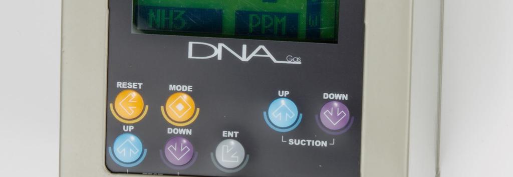
5 [Name and central function of section ] NO Description NO Description NO Description NO Description 1 Cover Case 13 Motor DOWN S/W 25 Pump 37 Alarm TB 2 Body Case 14 ENT Switch 26 Pump In 38 RS485 TB 3 LCD Display 15 JP3 27 Pump Out 4 Power LED 16 JP7 28 Sample Gas Inlet 5 Fault LED 17 JP2 29 Sample Gas Vent 6 AL1 LED 18 JP6 30 Cable Grand 7 AL2 LED 19 Flow Meter Out 31 Cover Fixed Screw 8 MODE Switch 20 FLOW METER 32 Battery Socket 9 RESET Switch 21 Flow Meter In 33 JP1 10 UP Switch 22 PHOTO TR 34 Fuse 11 DOWN Switch 23 Sensor Cap 35 Power/mA TB 12 Motor UP S/W 24 Sensor Out 36 Power Switch 5 page
6 1. Cover Case Sensor, Pump, and PCB board which are installed inside should be protected from external impact and environmental changes. 2. Body Case Sensor, Pump and Display board, Analog AMP board, Power board should be installed and protected from external impact and environmental changes. 3. LCD Display (128*64dot Graphic LCD) Gas density value measured at the sensor and setting parameter are displayed. 4. Power LED (Green) If power supply is normal, LED lights up. 5. Fault LED (Yellow) In case of fault circuit, erroneous setting of parameter, clogging of flow meter, the Fault LED lights up and fault signal outputs to the external contact signal. 6. AL1 LED (RED) If the density of measured gas is higher than the setting value of ALARM1, the LED blinks with 0.5 seconds interval, and the relay contact signal outputs externally. 7. AL2 LED(RED) If the density of measured gas is higher than the set value of ALARM2, the LED blinks with 0.25 seconds interval, and the relay contact signal outputs externally. 8. MODE Switch Function of entering into the setting mode at a normal condition. Press the MODE switch for longer than 3 seconds, and it enters into the setting mode. 9. RESET Switch Function of clearing external relay (In case of the kind of reset is manual at the setting menu). When in need of transfer the setting mode to the measuring mode, use the RESET Switch. 10. UP Switch This has a function of increasing the parameter value at the setting mode. 11. DOWN Switch This has a function of decreasing the parameter value at the setting mode. <11.1> UP+DOWN (TEST function) If the UP Switch and the DOWN Switch are simultaneously pressed for 3 seconds, the motion condition of the measured value, Alarm relay, Alarm LED, 4~20mA out put can be confirmed. 12. Motor UP Switch This has a function of increasing the sample gas volume. 13. Motor DOWN Switch This has a function of decreasing the sample gas volume. 6 page
7 14. ENT Switch This is used for storing the parameter value at the setting mode. 15. JP3 Connector This is a 40PIN Connector connecting Display PCB with AMP PCB. 16. JP7 Connector This is a 3PIN Connector connecting the out put signal cable at the Gas Sensor. 17. JP2 Connector This is a 2 PIN Connector connecting the out put electric signal cable at the Pump motor. 18,JP6 Connector This is a 20PIN Connector connecting POWER PCB with Analog PCB. 19. Flow Meter Out. Outlet direction of Flow Meter volume. 20. Flow Meter This indicates the Sample gas volume. The flowing velocity can be measured by the position of the ball. 21. Flow Meter In Inlet direction of Flow Meter volume. 22. PHOTO TR This has a function of inspecting if airflow is flowing or not. 23. Sensor Cap This is a place of inspecting gas leakage. 24. Sensor Out Outlet direction of the flow of Sensor Cap. 25. Pump A Motor generating the flow rate. 26. Pump In Inlet direction of the Pump flow rate. 27. Pump Out Outlet direction of the Pump flow rate. 28. Sample Gas Out Sample gas vent port (1/4 ) 29. Sample Gas Inlet Sample gas inlet port (1/4 ) 30. Cable Grand Power supply and signal Cable 31.Cover Fixed Screw A screw fixing the Cover case and Body. 32. Battery Socket 7 page
8 Power supply for storage of alarm data. 33. JP1 Connector Connector for downloading CPU Firmware. 34. FUSE Degaussing for protection of board when over-current occurs. 35. Power/4-20mA Terminal (24V, 0V, ma,e) Terminal for supplying power and connecting 4-20mA output. 36. Power Switch Power ON/OFF Switch. 37. Alarm Terminal Terminal for Fault, Alarm1, Alarm2, contacting output, 38. RS485 Terminal Terminal for data communication [ Illustration of Terminal ] Indicator DA-750 Terminal Block 8 page
9 [Setting of Menu] <Measuring Mode> <Setting Mode> 1.0 [MODE S/W] PUSH <LANGUAGE> KOREAN NH3 PPM ENGLISH Screen Screen [UP S/W] [RESET S/W] Dead Band Dead Time UNIT High Scale OFFSET Warming Up ALARM1 AL-TYPE1 Longview, Log Clear ALARM2 AL-TYPE2 COM CAL AL-RESET TIME Screen Scrren [DOWN S/W] Press MODE key for longer than 3 seconds at the measuring mode, and the setting mode is displayed (Screen2). Press ENT key after selecting one out of KOREAN,ENGLISH, and the next menu screen is displayed (Screen3). Whenever pressing DOWN key, the next menu is displayed. UNIT High Scale ALARM1 AL-TYPE1 ALARM2 AL-TYPE2 AL-RESET TIME Dead Band Dead Time OFFSET Warming Up Log View Log Clear COM CAL Whenever pressing UP key, the nest menu is displayed. UNIT High Scale ALARM1 AL-TYPE1 ALARM2 AL-TYPE2 AL-RESET TIME Dead Band Dead Time OFFSET Warming Up Log View Log Clear COM CAL Press ENT key, and Setting value is emerged. Press RETSET key, and Setting mode is changed to Measuring mode. 9 page
10 [Description of Menu in detail] N0 MENU DESCRIPTION 1 LANGUAGE Selection of language (KOREAN, ENGLISH) 2 UNIT Setting menu of Density unit of %,%LEL,PPM, 3 High Scale 20mA Setting menu comparing with Full Scale. 4 ALARM 1 Setting menu of Alarm1 value 5 AL-TYPE1 Kind of ALARM1 (H&H, L&L) 6 ALARM 2 Setting menu of Alarm2 menu 7 AL-TYPE2 Kind of ALARM2 (H&H, L&L) 8 AL-Reset Method for clearing Alarm 9 TIME Time adjustment 10 Dead Band ALARM DEAD BAND Menu. 11 Dead TIME ALARM DEAD TIME Menu 12 OFFSET Correction of error to measured value 13 Warming Up While power is supplied, time for initialization (0~99 seconds) 14 Log View Emerging menu of Alarm value 15 Log Clear Deleting menu of Log record 16 COM Setting menu of RS-485 communication. 17 CAL Correction of sensor (1) UNIT Setting of unit such as %, %LEL, PPM (2) High Scale Setting of 20mA compared with FULL SCALE. page 10
11 (ex) In case of setting SCALE: 100 In case of inputting 4mA analog: 0 Display In case of inputting 20mA analog: 100 Display (3) Alarm 1 Alarm output according to Kind1 setting. (ex1) ALARM-TYPE1: H&H, In case of setting Alarm value1: 20 In case that the display value is more than 20, ALARM1 operates. (ex2) ALARM-TYPE1: L&L, In case of setting Alarm value1: 20 In case that the display value is less than 20, ALARM1 operates. (4) AL-TYPE1 For inflammable or toxic gas: H&H(In case of more than the setting value, Alarm1 operates) For oxygen: L&L(In case of less than the setting value, Alarm1 operates) (5) Alarm 2 According to setting of kind 2, Alarm is output. (ex1) ALARM-TYPE2: In case of setting H&H, Alarm value 2: 20 In case that the display value is more than 20, ALARM2 operates. (ex2) ALARM-TYPE2: In case of setting L&L, Alarm value 2: 20 In case that the display value is less than 20, ALARM2 operates. (6) AL-TYPE2 For inflammable or toxic gas: H&H (In case of more than the setting value, Alarm2 operates) For oxygen: L&L(In case of less than the setting value, Alarm2 operates) (7) AL-Reset ALARM relay. AUTO HAND selectable. -AUTO: Regardless of the reset switch, LED is changed according to setting value. -HAND: Only if the reset switch is pressed, the Relay, LED are changed (8) Time Adjustment Setting Menu of year, month, day, hour, minute, second. page 11
12 (9) ALARM DEAD BAND As ON/OFF of the relay output continues near the Alarm setting value, this function exerts hysteresis value in order to eliminate this phenomenon. (ex1) In case of ALARM1: 20, ALARM TYPE: H&H, D-BAND:3 In case that the display value is more than 20, ALARM1 ON In case of less than 17, ALARM1 OFF. (ex2) In case of ALARM1: 20, ALARM TYPE: L&L, D-BAND:3 In case that the display value is less than 20, ALARM1 ON In case of more than 23, ALARM1 OFF. (10) Dead time (ALARM DELAY TIME) This is a menu for preventing an instant error by an effect of external impact or noise, etc. not by normal action of the sensor. (ex) In case of Alarm value: 50, DEAD TIME: 5 In case that the measured value is maintained for longer than 5 seconds with more than the Alarm setting value, it is regarded as Alarm value. (11) OFFSET (Correction of the measured value) Error to the measured value occurred at the sensed part is offset with plus and minus. (ex) In case of setting OFFSET: +5. In case that the output error at the sensed part is?5, the actual display is indicated?5, but by correcting of OFFSET as much as +5, the display is shown 0. (12) Warming up When power is supplied, time for initialization is set. (13) Log View Alarm value stored at memory is shown on the LCD screen. (14) Log Clear All information of alarm value stored at memory are deleted. (15) COM(Setting of communication) RS-485 Baud rate is set RS-485 Local number is set (16) CAL(Correction of sensor) (1.1) ZERO CALIBRATION page 12
13 Press ENT KEY at the state of CAL [ZERO], and an optional value of ZERO GAS READ..<0.0 %> is shown. And, by using a correction device, inject clean air or 100% nitrogen into 500ml/min flow volume for 1 minute. When the measured value became stable after injection of gas, press ENT KEY, and SUCCESS is shown. However, if the correction does not succeed, FAIL is shown for 2 seconds. <Caution> In case of the cancellation of the correction, press the RESET KEY. (1.2) SPAN CALIBRATION At the state of CAL [SPAN], press ENT KEY and an optional value of SPAN RANGE <20.9 %> is shown. Using UP,DOWN KEY, input the standard gas value. Press ENT KEY again, and an optional value of SPAN GAS READ. [20.9%] is shown. Using a correction device, inject standard gas into sensor part, and the flow volume of 500Ml/min into the detection degaussing. After injection of gas, when the measured value became stable, press ENT KEY, and SUCCESS is shown. However, if the correction was not succeeded, FAIL is shown for 2 seconds. <Caution> In case of cancellation of the correction, press the RESET KEY, [External Dimension] POWER FAULT AL1 AL F L O NH3 PPM W RESET MODE UP DOWM UP DOWN ENT MOTOR TEST 정면도 Front 측면도 Side page 13
SMART Gas Detector/Transmitter(4~20mA) with built-in LCD & explosion proof DA-500
 with built-in LCD & explosion proof DA-500") SMART Gas Detector/Transmitter(4~20mA) with built-in LCD & explosion proof DA-500 C-910C, Bupyeong Woolim Lion s Valley, #425, Cheongcheon-Dong, Bupyeong-Gu, Incheon, Korea TEL: +82-32-623-7507 FAX: +82-32-623-7510
SMART Gas Detector/Transmitter(4~20mA) with built-in LCD & explosion proof DA-500 C-910C, Bupyeong Woolim Lion s Valley, #425, Cheongcheon-Dong, Bupyeong-Gu, Incheon, Korea TEL: +82-32-623-7507 FAX: +82-32-623-7510
Carbon Monoxide Transmitter
 Introduction The CO Transmitter uses an electrochemical sensor to monitor the carbon monoxide level and outputs a field-selectable 4-20 ma or voltage signal. The voltage signal may also be set to 0-5 or
2-Channel Smoke Detector SD - 110
 2-Channel Smoke Detector SD - 110 GASDNA CO., LTD. Rm910C, Cdong Bupyeong Woolim Lion s Valley, #425, Cheongcheon-Dong, Bupyeong-gu, Incheon Korea TEL:+82-32-623-7507, FAX:+82-32-623-7510 Website: Http://www.gasdna.com
Table of Contents 1. OVERVIEW SYSTEM LAYOUT SPECIFICATIONS FUNCTION... 11
 Table of Contents 1. OVERVIEW... 3 2. SYSTEM LAYOUT... 4 3. SPECIFICATIONS... 8 3.1 SYSTEM COMPONENTS...9 3.2 PLC INPUTS AND OUTPUTS...9 3.3 FUNCTION KEYS...10 3.4 DEFAULT SET POINTS AND TIMERS...10 4.
INSTALLATION AND OPERATING INSTRUCTIONS
 INSTALLATI AND OPERATING INSTRUCTIS PRODUCTS CMD Series CO Detectors FGD Series Refrigerant Detectors AGD Series Toxic Gas Detectors CGD Series Combustible Gas Detectors (All transmitters are factory set
Multi-Channel Gas Detector Monitoring Unit GMS
 Multi-Channel Gas Detector Monitoring Unit GMS - 2000 C-910C, Bupyeong Woolim Lion s Valley, #425, Cheongcheon-Dong, Bupyeong-Gu, Incheon, Korea TEL: +82-32-623-7507 FAX: +82-32-623-7510 E-mail: sales@gasdna.com
Model D12-IR. Digital Gas Transmitter...
 Model D12-IR Digital Gas Transmitter... ATI s Series D12 gas transmitter line now includes a versatile Infrared system that can be configured for LEL or select toxic gases. The D12-IR utilizes a compact
Two-Channel Gas Controller
 Two-Channel Gas Controller Specifications subject to change without notice. USA 09 Page of DESCRIPTION Highly configurable, UL 0 performance-tested and -certified, and wall-mounted gas monitor; continuously
Analog Room Pressure Monitor RPC Series
 Description The Room Pressure Monitor is used to measure differential pressure in the range of 0.125 to 1"wc or 30 to 250 Pa. It combines precision high sensitivity silicon sensing capabilities and the
EAGLE 2. 6 Channel Capacity. Inlet fitting. Loud buzzer (95dB) IrDA communication port Low flow shutoff and alarm Alarm LED s with wide visibility
 IrDA communication port Low flow shutoff and alarm Alarm LED s with wide visibility") EAGLE 2 Inlet fitting Loud buzzer (95dB) IrDA communication port Low flow shutoff and alarm Alarm LED s with wide visibility Internal / external hydrophobic filters Self healing polyurethane protective
EAGLE 2 Inlet fitting Loud buzzer (95dB) IrDA communication port Low flow shutoff and alarm Alarm LED s with wide visibility Internal / external hydrophobic filters Self healing polyurethane protective
Indoor Oxygen Monitor OX-600 Operating Manual
 PT2E-1882 Indoor Oxygen Monitor OX-600 Operating Manual Contents 1 Outline of the Product... 3 Preface... 3 Purpose of use... 3 Definition of DANGER, WARNING, CAUTION and NOTE... 4 Method of confirmation
Toxic Gas Detection. Model F12. Toxic Gas Detection
 Toxic Gas Detection Model F12 Toxic Gas Detection Smart Sensor Technology The Series F12 Gas Transmitter is an Intrinsically Safe (IS) version of our explosion-proof D12 transmitter. In its standard form,
BST-MG08/09 Multi-gas Detecting Alarm. Manual Instruction
 BST-MG08/09 Multi-gas Detecting Alarm Manual Instruction 1. Application: This product is designed to ensure safety for users who work in dangerous places. It s used for detecting CO, O2, H2S, CH4 simultaneously
GMA 301. Operation Manual. Worldwide Supplier of Safety Solutions. Part Number
 Worldwide Supplier of Safety Solutions GfG Instrumentation 1194 Oak Valley Drive #20 Phone: 734-769-0573 Fax: 734-769-1888 E-Mail: info@gfg-inc.com Internet: www.gfg-inc.com GMA 301 Operation Manual Part
Air Check EX LEL Gas Monitor Instruction Manual
 Air Check EX LEL Gas Monitor Instruction Manual PureAire Monitoring Systems, Inc. 1140 Ensell Road Lake Zurich, Illinois 60047 Phone: 847-726-6000 Fax: 847-726-6051 Toll-Free: 888-788-8050 www.pureairemonitoring.com
Warranty Registration
 WARRANT Y AND LIMITS OF LIABILIT Y Vulcain Inc. warrants to the original purchaser that its product, and the component parts thereof, will be free from defects in workmanship and materials for a period
User Manual System 11
 User Manual System 11 www.pulseinstrument.com Copyright 2007 Pulse Instruments All Rights Reserved 943 Flynn Road, Camarillo, CA 93012 Phone: (800) 462-1926 Fax: (800) 878-9172 SYSTEM 11 Water Disinfection
QD6310. Fixed Gas Detector Operation Manual
 QD6310 Fixed Gas Detector Operation Manual Safety Information Before using the device, please first carefully read and follow the following information to operate the device: Please don't use the defective
5 Operating Modes GX Smallest 6 gas sample draw PID library of over 600 VOC s 2 Interchangable smart sensor slots
 5 Operating Modes GX-6000 Smallest 6 gas sample draw PID library of over 600 VOC s 2 Interchangable smart sensor slots GX-6000 5 Operating modes Normal Leak Check Inert Bar hole Snap Log Monitor up to
Pioneer-R16 Gas Monitor Operator s Manual
 Pioneer-R16 Gas Monitor Operator s Manual Edition 7/2/97 RKI INSTRUMENTS, INC RKI Instruments, Inc. 33248 Central Ave, Union City, CA 94587 (510) 441-5656 Chapter 1: Description About the Pioneer-R16 Gas
5 Operating Modes GX Smallest 6 gas sample draw PID library of over 600 VOC s 2 Interchangable smart sensor slots
 5 Operating Modes GX-6000 Smallest 6 gas sample draw PID library of over 600 VOC s 2 Interchangable smart sensor slots CONFINED SPACE ENTRY Monitor LEL, O2, CO, and H2S Internal sample pump Pull samples
Nitrogen Dioxide (NO2) Single-Point Gas Detection System
 Single-Point Gas Detection System") Nitrogen Dioxide (NO) Single-Point Gas Detection System DESCRIPTION Wall-mounted gas monitor with built-in nitrogen dioxide (NO)/diesel fume gas sensor, accepts one analog remote device such as a secondary
Nitrogen Dioxide (NO) Single-Point Gas Detection System DESCRIPTION Wall-mounted gas monitor with built-in nitrogen dioxide (NO)/diesel fume gas sensor, accepts one analog remote device such as a secondary
4-20mA CYBER Cyber Transmitter for flammable, toxic and IR gas detection Cyber Head Increased security in ATEX certified head
 4-20mA CYBER Cyber Transmitter for flammable, toxic and IR gas detection Cyber Head Increased security in ATEX certified head NET DRAFT version 2.1-2008 Pag. 1 4-20mA Cyber - DRAFT version 2.1-2008 Pag.
GG-2 2-CHANNEL GAS DETECTION CONTROL PANEL. Installation and Operation Manual
 GG-2 2-CHANNEL GAS DETECTION CONTROL PANEL Installation and Operation Manual 2 GG-2 Warning Use this product only in the manner described in this manual. If the equipment is used in a manner not specified
MODEL: SP2nd (Portable Single Gas Detector) Operating Manual
 Operating Manual") MODEL: SP2nd (Portable Single Gas Detector) Operating Manual Edaphic Scientific Pty Ltd www.edaphic.com.au info@edaphic.com.au Guarantee and Repair Senko Co., Ltd. guarantees the products of SP series
MODEL: SP2nd (Portable Single Gas Detector) Operating Manual Edaphic Scientific Pty Ltd www.edaphic.com.au info@edaphic.com.au Guarantee and Repair Senko Co., Ltd. guarantees the products of SP series
S304 and S305 Dust Emission Monitors. User Manual. Distributor
 S304 and S305 Dust Emission Monitors User Manual Distributor Version 6.4 30/5/2012 Table of Contents 1. INTRODUCTION... 3 1.1 Safety... 3 1.2 Product overview... 4 1.3 Principle of operation... 4 2. INSTALLATION...
PureAire Combo O 2 / CO 2 Monitor
 PureAire Combo O 2 / CO 2 Monitor Instruction Manual PureAire Monitoring Systems, Inc. 557 Capital Drive Lake Zurich, Illinois 60047 Phone: 847-726-6000 Fax: 847-726-6051 Toll-Free: 888-788-8050 pureairemonitoring.com
Meridian wiredhart. HART Field Device Specification Goldmine Rd. Monroe, NC USA
 HART Field Device Specification Meridian wiredhart 4320 Goldmine Rd. Monroe, NC 28110 USA HART is a registered trademark of the HART Communication Foundation TABLE OF CONTENTS 1. Introduction...5 1.1 Scope...5
MX43. Analog and digital controller. 4 or 8 lines / 16 to 32 detectors max. Highly versatile controller. Cost savings on wiring installation
 Gas Detection Control Panel MX Analog and digital controller or 8 lines / 6 to s max Highly versatile controller Cost savings on wiring installation The Fixed Gas Detection People www.oldhamgas.com an
MODEL: SP12C7. (Portable 4 gas detector) Operating Manual
 Operating Manual") MODEL: SP12C7 (Portable 4 gas detector) Operating Manual Guarantee and Repair Senko Co., Ltd. guarantees the products of SP series for 24 months from the shipping date and repairs or replaces the defected
MODEL: SP12C7 (Portable 4 gas detector) Operating Manual Guarantee and Repair Senko Co., Ltd. guarantees the products of SP series for 24 months from the shipping date and repairs or replaces the defected
S/601 Controller Installation Manual
 Checked Version Release date QA V4.6.5 PC1 EN 02.07.2012 2011 S/601 Controller Installation Manual FLOW CONTROL PC1 - Pump controller Introduction Thank you for using the S/601 flow, batch and pump control
ACCURATE ELECTRONICS INC
 ACCURATE ELECTRONICS INC Page 1 of 7 Model 108078 2 Sept 09 WWW.ACCURATE.ORG PO BOX 1654 97075-1654 8687 SW Hall Blvd 97008 BEAVERTON OR USA 503.641.0118 FAX 503.646.3903 Practice Section 108078 Rev A
Mark 25 Ultrapure Water Conductivity Analyzer
 Martek Instruments, Inc. Mark 25 Ultrapure Water Conductivity Analyzer Instruction Manual WARRANTY POLICY Unless otherwise stated, MARTEK INSTRUMENTS, INC. warrants this equipment to be free from defects
OPERATING INSTRUCTION MANUAL FOR OPTICAL INTERFEROMETIC GAS ANALYZER MODEL FI-800
 PT3E-0271 OPERATING INSTRUCTION MANUAL FOR OPTICAL INTERFEROMETIC GAS ANALYZER MODEL FI-800 FOR USERS Safety Precautions 1. Read and understand the instructions in this manual before operating this instrument.
2-wire Passive Intelligent Loop (LED) Display Meter
 Display Meter") Features Two-wire passive intelligent loop current (LED) digital meter 2-wire Passive Intelligent Loop (LED) Display Meter Embedded 2-wire Passive Programmable 4-20mA Loop (Four Digits LED) Display Meter
Features Two-wire passive intelligent loop current (LED) digital meter 2-wire Passive Intelligent Loop (LED) Display Meter Embedded 2-wire Passive Programmable 4-20mA Loop (Four Digits LED) Display Meter
IMR IX176 Portable Gas Detector User Manual
 IMR Portable Gas Detector User Manual Read this manual carefully before using this device. (727) 328-2818 / (800) RING-IMR Fax: (727) 328-2826 www.imrusa.com Ver. 1.0A4 CONTENTS SERVICE GUIDELINES... 3
DSGH. Radiation-Based Detector with GEN2000 Electronics for Density Measurement QUICK REFERENCE GUIDE
 DSGH Radiation-Based Detector with GEN2000 Electronics for Density Measurement QUICK REFERENCE GUIDE Revision History Revision History Version of manual Description Date 1.0 Initial release 051025 1.1
Toxic and Explosive Smart Gas Monitor PN / Installation and User Manual
 Toxic and Explosive Smart Gas Monitor PN 151022/151023 Installation and User Manual Quest Controls, Inc. 208 9 th Street Dr. West Palmetto, FL 34221 www.questcontrols.com Phone: (941) 729-4799 Fax: (941)
Inc Series Digital Gas Detector/Controller. Operation Manual
 5 Series Digital Gas Detector/Controller Operation Manual TABLE OF CONTENTS 1. 2. 3. 4. 5. 6. 7. General Description 1.1 Applications 1.2 Features Model Selection Guide Characteristics Installation 4.1
Universal Gas Detector
 Universal Gas Detector Instruction Manual PureAire Monitoring Systems, Inc. 557 Capital Drive Lake Zurich, Illinois 60047 Phone: 847-726-6000 Fax: 847-726-6051 Toll-Free: 888-788-8050 pureairemonitoring.com
ECOLOG TN2, TN3-P, TN4, TN4-L, TP2, TP4-L,TH1, TH2
 TN2, TN3-P, TN4, TN4-L, TP2, TP4-L,TH1, TH2 1. Product Overview 1.1 Display Large LCD display for measured values and status Time Alarm (will stay lit until Upper / Lower limit value (except for TN2) the
E1000 Portable gas detector
 E1000 Portable gas detector Operation manual Ver:HWWM161229CG Read this manual carefully before using the device Table of Contents SAFETY INFORMATION... - 1-1. BRIEF INTRODUCTION... - 3-2. MAIN FUNCTION
Analog and digital controller. 4 or 8 lines / 16 to 32 detectors max. Highly versatile controller. Cost savings on wiring installation
 Gas Detection Control Panel Analog and digital controller 4 or 8 lines / 6 to detectors max Highly versatile controller Cost savings on wiring installation Certifications The The Fixed Fixed Gas Gas Detection
BST-MG07 Multi-gas Detecting Alarm Manual Instruction
 BST-MG7 Multi-gas Detecting Alarm Manual Instruction 1. Application This BST-MG7 multi gas detecting alarm is applied to underground coal mine, petrochemical industry, municipal, environmental protection
Ammonia Leak Detector Manual
 Ammonia Leak Detector Manual Document No. 70-PHW-1023-R2.5 No part of this publication may be reproduced, stored in a retrieval system, or transmitted, in any form or by any means, electronic, mechanical,
MODEL: SP12C7. (Portable 4 gas detector) Operating Manual
 Operating Manual") MODEL: SP12C7 (Portable 4 gas detector) Operating Manual Guarantee and Repair Senko Co., Ltd. guarantees the products of SP series for 24 months from the shipping date and repairs or replaces the defected
MODEL: SP12C7 (Portable 4 gas detector) Operating Manual Guarantee and Repair Senko Co., Ltd. guarantees the products of SP series for 24 months from the shipping date and repairs or replaces the defected
IMR EX610. Portable Gas Detector. Operation Manual
 IMR EX610 Portable Gas Detector Operation Manual IMR Environmental Equipment, Inc. 3634 Central Ave. St. Petersburg, FL 33711 Phone: 727-328-2818 email: info@imrusa.com Read this manual carefully before
VT4810 SINGLE / DUAL ZONE CONTROLLER INSTALLATION MANUAL
 Thermocouple Type BS4937 (IEC584-3): Outer / + / - BS1843 (Old UK Standard) Outer / + / - US Outer / + / - J : Iron / Copper-Nickel Black / Black / White Black / Yellow / Blue Black / White / Red VT4810
EST User Manual. (Please read this manual carefully before using)
") EST-1000 Handheld Intelligent Toxic Gas Detector User Manual (Please read this manual carefully before using) ENVIRONMENTAL SENSOR TECHNOLOGY CO.INC. Contents I. Product Overview...1 II. Product Description...1
EST-1000 Handheld Intelligent Toxic Gas Detector User Manual (Please read this manual carefully before using) ENVIRONMENTAL SENSOR TECHNOLOGY CO.INC. Contents I. Product Overview...1 II. Product Description...1
No part of this publication may be reproduced, stored in an automated data file or made public in any form or by any means, whether electronic,
 No part of this publication may be reproduced, stored in an automated data file or made public in any form or by any means, whether electronic, mechanical, by photocopying, recording or in any other manner
Analox 1000 Series. User Manual. Analox Sensor Technology Ltd. 15 Ellerbeck Court, Stokesley Business Park North Yorkshire, TS9 5PT, UK
 Analox 1000 Series User Manual Analox Sensor Technology Ltd. 15 Ellerbeck Court, Stokesley Business Park North Yorkshire, TS9 5PT, UK T: +44 (0)1642 711400 F: +44 (0)1642 713900 W: www.analox.net E: info@analox.net
DFM. flow pressure temperature MULTI PARAMETER DIGITAL MASS FLOW METERS. Totalizer. Interface
 Multi Parameter flow meters provide accurate data on three different fluid parameters: flow pressure temperature The flow rate can be displayed in volumetric flow or mass flow engineering units for standard
Technicians Manual Single Compressor
 Technicians Manual Single Compressor HAC-FF-D WALL PAD Operating Manual Version PCB Version V2.3.5 Version wall pad Version Manual Page 1 Contents 1. Main features 2. Main technical data 3. Wall pad 4.
MX43. Analog and digital controller. 4 or 8 lines / 16 to 32 detectors max. Highly versatile controller. SIL1 reliability. Gas Detection Control Panel
 Gas Detection Control Panel MX Analog and digital controller or 8 lines / 6 to s max Highly versatile controller SIL reliability Fixed The Fixed Gas Gas Detection Detection Experts People www.oldhamgas.com
Air Check O 2 Deficiency Monitor 0-25%
 Air Check O 2 Deficiency Monitor 0-25% Instruction Manual RS-485 Revision 4.05 Part number 99066 PureAire Monitoring Systems, Inc. 557 Capital Drive Lake Zurich, Illinois 60047 Phone: 847-726-6000 Fax:
Micro-controller X C C1 C2 AL1 AL2 AL3. Model: PXR4/5/9. Operation Manual SEL PXR. ECNO:406e
 C C1 C2 AL1 AL2 AL3 Micro-controller X Model: PXR4/5/9 PXR SEL Operation Manual ECNO:46e Table of Contents Part Names and Functions... 6 Operations... 7 2-1 Parameter list... 7 2-2 Basic operations...
Ventostat Wall Mount. Amphenol Advanced Sensors. Telaire Wall Mount CO 2. , Humidity and Temperature Transmitters. Features:
 Ventostat Wall Mount Telaire Wall Mount, Humidity and Temperature Transmitters Features: Patented, Absorption Infrared Gas sensing engine provides high accuracy in a compact low cost package. Patented
2-wire Passive Intelligent Loop (LED) Display Meter
 Display Meter") Features Two-wire passive intelligent loop current (LED) digital meter 2-wire Passive Intelligent Loop (LED) Display Meter Embedded 2-wire Passive Programmable 4-20mA Loop (Four Digits LED) Display Meter
Features Two-wire passive intelligent loop current (LED) digital meter 2-wire Passive Intelligent Loop (LED) Display Meter Embedded 2-wire Passive Programmable 4-20mA Loop (Four Digits LED) Display Meter
DWYER INSTRUMENTS, INC. P.O. BOX 373 MICHIGAN CITY, INDIANA 46360, U.S.A. Series 670 Hood Monitor. Bulletin AV-670
 Bulletin AV-670 Series 670 Hood Monitor Specifications - Installation and Operating Instructions DWYER INSTRUMENTS, INC. P.O. BOX 373 MICHIGAN CITY, INDIANA 46360, U.S.A. Phone: 219/879-8000 Fax: 219/872-9057
Tri-Tech Medical Inc.
 Submittal Data Sheet Project Information Project Number Approval Features The Tri-Tech Area and Master Alarm Panel digitally displays gas pressure (1 psi increments) monitors and displays normal and alarm
Oxygen (O2) Single-Point Gas Detection System
 Single-Point Gas Detection System") Oxygen (O) Single-Point Gas Detection System DESCRIPTION Wall-mounted gas monitor with built-in oxygen (O) sensor, accepts one analog remote device such as a secondary gas sensor, temperature or humidity
Oxygen (O) Single-Point Gas Detection System DESCRIPTION Wall-mounted gas monitor with built-in oxygen (O) sensor, accepts one analog remote device such as a secondary gas sensor, temperature or humidity
CO2 & Oxygen Monitor Operating Instructions Model: RAD
 CO2 & Oxygen Monitor Operating Instructions Model: RAD-0200-2 Table of Contents 1. Overview 2. Package Contents and Description 3. Strobes (Optional) 4. LCD Display Symbols 5. SEU (Main Sensor Unit) 6.
Danfoss gas detection units
 Data sheet Danfoss gas detection units Types GD Premium, Premium+, Premium Duplex, Premium Remote, Premium Flex and Premium Uptime The Premium line gas detection units are used for monitoring and warning
Oxygen Monitor Operating Manual
 Oxygen Monitor Operating Manual Model: RAD-0002 Remote Oxygen Storage Safety System 1. Product Description Thank you for selecting the RAD-0002 Remote Oxygen Storage Safety System. This monitor is designed
SmarTemp Control fx 2.0
 Digital Timer Interface Installation / Operation Instructions General Thank you for choosing Webasto to meet your heating needs. The Webasto SmarTemp Control fx 2.0 enables you to preset start-up cycles
QA16 Addressable System
 QA16 Addressable System Operating Manual HORING LIH INDUSTRIAL CO., LTD. www.horinglih.com QA16 System Characteristics Each loop can connect with 250 devices. Easy system programming through PC to panel.
Danfoss gas detection unit Type GD Heavy Duty
 Data sheet Danfoss gas detection unit Type GD Heavy Duty The Heavy Duty gas detection units are used for monitoring and warning of hazardous Ammonia gas concentrations. They are intended for ATEX/ IECEx
Stand Alone DYNAGARD SP Operation Manual
 Stand Alone DYNAGARD SP Operation Manual Contents Page General Description 1 Detection Principle 1 For Your Safety 1 Design 2 Mounting 2 Mounting Position of DYNAGARD SP 2 Installation of Electrical Connections
Beacon 200 Gas Monitor Operator s Manual. Part Number: RK Released: 6/6/08
 Beacon 200 Gas Monitor Operator s Manual Part Number: 71-2102RK Released: 6/6/08 Table of Contents Chapter 1: Introduction.................................................3 Overview.............................................................3
Self-contained and intrinsically safe wireless stand-alone multi-point gas detector.
 Introduction United Safety applies the detection system as a multi-point monitoring for toxic gases, combustibles and oxygen hazards. Self-powered and solar-capable, the features unequaled versatility,
Air Check Ex O 2 Deficiency Monitor
 Air Check Ex O 2 Deficiency Monitor Instruction Manual Part number 99020 PureAire Monitoring Systems, Inc. 1140 Ensell Road Lake Zurich, Illinois 60047 Phone: 847-726-6000 Fax: 847-726-6051 Toll-Free:
Software Version 2.01 LEVEL MONITOR MODEL 220
 Software Version 2.01 LEVEL MONITOR MODEL 220 19 April 2000 CONTENTS 1. Introduction 1 1.1 Model Number Designation 2 1.2 Intrinsic Safety Considerations 3 2. Specification 4 3. Operation 6 3.1 Display
GASGUARDIAN Channel Controller OPERATING & INSTALLATION MANUAL
 GASGUARDIAN 2 3 2-Channel Controller OPERATING & INSTALLATION MANUAL GasGuardian 2 3 Operating and Installation Manual Table of Contents General description.... 3 Installation. 3 Locating the GasGuardian-2..
EKC 347 Liquid Level Controller REFRIGERATION AND AIR CONDITIONING. Manual
 EKC 347 Liquid Level Controller REFRIGERATION AND AIR CONDITIONING Manual Contents Introduction...3 Valve compatibility...3 Features...3 Application examples...3 Ordering...3 Operating the EKC 347...4-5
INSTALLATION AND OPERATION INSTRUCTIONS Before Installing or Operating, Read and Comply with These Instructions
 ADI5775-B INSTALLATION AND OPERATION INSTRUCTIONS Before Installing or Operating, Read and Comply with These Instructions Controls Corporation of America 1501 Harpers Road Virginia Beach, VA 23454 To Order
M2A Transmitter Operator s Manual
 M2A Transmitter Operator s Manual Part Number: 71-0305RK Revision: F Released: 1/8/18 RKI Instruments, Inc. www.rkiinstruments.com WARNING Read and understand this instruction manual before operating instrument.
ANALOX 5001 Carbon Dioxide Monitor. User Manual ANALOX Analox 5001 Carbon Dioxide Monitor User Manual
 ANALOX 5001 ANALOX 5001 Carbon Dioxide Monitor User Manual Analox Sensor Technology Ltd 15 Ellerbeck Court, Stokesley Business Park North Yorkshire, TS9 5PT T: +44 (0)1642 711400 F: +44 (0)1642 713900
User Manual. Digi-Sense TC9500 Advanced Multiparameter Temperature Controller with Thermocouple, Thermistor, and RTD Inputs
 User Manual Digi-Sense TC9500 Advanced Multiparameter Temperature Controller with Thermocouple, Thermistor, and RTD Inputs Models 89800-03 and 89800-04 THE STANDARD IN PRECISION MEASUREMENT Table of Contents
EMS510 Electrical Wiring Guide Volume 2, Rev 1.4
 EMS510 Electrical Wiring Guide Volume 2, Rev 1.4 Prepared by Michael L. Kominske Environmental Monitor Service Inc. PO Box 4340 Yalesville, CT 06492 Phone 203.935.0102 Fax 203.634.6663 Email: sales@emsct.com
P R O D U C T S P E C I F I C A T I O N MSA Ultima X Series Sensor/Transmitter Specification
 P R O D U C T S P E C I F I C A T I O N MSA Ultima X Series Sensor/Transmitter Specification 1.0 This specification details the attributes and operating characteristics of the MSA Ultima X Series sensors/transmitters.
Series 9000 Total Hydrocarbon Analyzer
 Series 9000 Total Hydrocarbon Analyzer Analyzer The Baseline Series 9000 is the candidate of choice whenever accurate, reliable total hydrocarbon analysis is required. The Series 9000 analyzer provides
SAFETY CERTIFIED MODEL FP-700 COMBUSTIBLE GAS DETECTOR
 SAFETY MANUAL SIL 2 Certified Model FP-700 Combustible Hydrocarbon Gas Sensor Version 2.0 1 SAFETY CERTIFIED MODEL FP-700 COMBUSTIBLE GAS DETECTOR This manual addresses the specific requirements and recommendations
INSTRUCTION MANUAL. Software Revision Card 3.2 DOCUMENT SES-KS E REV. 3
 2402 COMBUSTIBLE GAS CARD 2 CHANNELS 2404 TOXIC GAS CARD 2 CHANNELS 2407 OXYGEN GAS CARD 2 CHANNELS INSTRUCTION MANUAL Software Revision Card 3.2 DOCUMENT SES-KS-2402-04-07-E REV. 3 2402 2404 2407-2 CHANNELS
CLEANROOM MONITOR CR3A Network - Installation Instructions
 CLEANROOM MONITOR CR3A Network - Installation Instructions INTRODUCTION The CR3 Series Cleanroom Monitor, was developed specifically to allow for monitoring of confined spaces with accuracy and reliability.
Model D12. Digital Gas Transmitter
 Model D12 Digital Gas Transmitter Gas detection systems come in all shapes and sizes. Some require simple 4-20 ma transmission. Some are better suited to local alarm relay functions. Some really require
CO2 Monitor Operating Instructions
 1. Product Overview CO2 Monitor Operating Instructions Model: RAD-0102-6 Remote CO2 Storage Safety System Thank you for selecting the RAD-0102-6 CO2 Storage Safety Alarm. This monitor is designed to detect
Remote Display Alarm Indicator for Oxygen monitor
 Remote Display Alarm Indicator for Oxygen monitor (Part number 99091) The Remote Display Alarm Indicator is designed to display remote oxygen concentration information from PureAire oxygen monitors. All
RPM1600 Series Room Pressure Monitors
 RPM1600 Series Room Pressure Monitors Technical Bulletin LB-RPM1611-0, LB--0 Code No. LIT-12012228 Issued October 2017 Refer to the QuickLIT website for the most up-to-date version of this document. How
DPR-145 TEMPERATURE PROTECTION RELAY. DPR-145 User Manual V-2.0 ( ) PT100 INPUTS: 4 RELAY OUTPUTS: 4 RS-485 MODBUS PORT VDC SUPPLY -1-
 PT100 INPUTS: 4 RELAY OUTPUTS: 4 RS-485 MODBUS PORT VDC SUPPLY -1-") DPR-45 User Manual V-2.0 (2..206) DPR-45 TEMPERATURE PROTECTION RELAY PT00 INPUTS: 4 RELAY OUTPUTS: 4 RS-485 MODBUS PORT 9-50VDC SUPPLY DESCRIPTION DPR-45 is a precision unit designed for the temperature
DPR-45 User Manual V-2.0 (2..206) DPR-45 TEMPERATURE PROTECTION RELAY PT00 INPUTS: 4 RELAY OUTPUTS: 4 RS-485 MODBUS PORT 9-50VDC SUPPLY DESCRIPTION DPR-45 is a precision unit designed for the temperature
Operating Manual Hand-held Measuring Device GMH 3690 GL. for Gaseous Oxygen and Temperature with Alarm Function
 H36.0..6C-07 page of 8 Operating Manual Hand-held Measuring Device GMH 3690 GL for Gaseous Oxygen and Temperature with Alarm Function Version.3 How to Operate and Maintain Device: H36.0..6C-07 page of
User and Installation manual
 Toxic, explosive and oxygen gas detection control panel User and Installation manual FS82426 2018 DURAN ELECTRONICA S.L. - All rights reserved www.duranelectronica.com RANGE OF COMPATIBLE PRODUCTS Remote
Rev B, 9/2/2009. Kodiak Chiller Overview
 930-0001 Rev B, 9/2/2009 Kodiak Chiller Overview Presentation Outline Phone: 781-933-7300 Lytron Technical Support Contact Information 3 Introduction 4 Part I: Unpacking 5 Part II: Installation 7 Part
VERTEX VT10 SERIES PID OPERATION MANUAL MICROPROCESSOR BASED PID CONTROLLER
 1 VERTEX VT10 SERIES PID OPERATION MANUAL MICROPROCESSOR BASED PID CONTROLLER 1. INTRODUCTION This manual contains information for the installation and operation and tuning of our Vertex VT10 series self-tuning
HALOGUARD IR MULTI-POINT, COMPOUND SPECIFIC MONITOR INSTRUCTION MANUAL
 HALOGUARD IR MULTI-POINT, COMPOUND SPECIFIC MONITOR INSTRUCTION MANUAL S E R I A L N O. M O D E L N O. T e m p. R a n g e 1 - = > 6 0 o F 2 - = 4 0-6 0 o F 3 - = < 4 0 o F - G a s T y p e 1 - R -1 1 2
DGS - Danfoss Gas Sensor Check / Calibration Procedure
 User Guide DGS - Danfoss Gas Sensor Check / Calibration Procedure ADAP-KOOL Refrigeration Control System Content 1 - Introduction... 2 2 - Bump Test... 4 3 - Calibration... 5 4 - Additional recommendations...
Air Check O 2 Deficiency Monitor
 Air Check O 2 Deficiency Monitor Instruction Manual PureAire Monitoring Systems, Inc. 557 Capital Drive Lake Zurich, Illinois 60047 Phone: 847-726-6000 Fax: 847-726-6051 Toll-Free: 888-788-8050 pureairemonitoring.com
VASTHI ENGINEERS. Vasthi Multi Gas Monitor/Analyzer. Sheet No. 1 of 4. Vasthi Multi Gas monitor/analyzer with alarm and Graphical Display.
 Sheet No. 1 of 4 monitor/analyzer with alarm and Graphical Display. Sheet No. 2 of 4 It specially designed to analyze any gas of your choice, its automatic operation, accurate measurement and crystal clear
Counting Scales. HC-i Series.
 Counting Scales HC-i Series www.phoenixscales.co.uk Simple and Easy Operation with High Performance Counting Function! With the HC-i series and its accessories, you can easily build an inexpensive inventory
ORP (mv) Controller Model: ORP-XP2. UP DOWN ENTER Time & Date Main Menu Alarm Reset
 Controller Model: ORP-XP2. UP DOWN ENTER Time & Date Main Menu Alarm Reset") Instruction Manual ORP (mv) Controller Model: ORP-XP2 Power Control Alarm Comms UP DOWN ENTER Time & Date Main Menu Alarm Reset Supplied by: Convergent Water Controls Pty Ltd 2/4 Huntley Street, PO Box
Instruction Manual ORP (mv) Controller Model: ORP-XP2 Power Control Alarm Comms UP DOWN ENTER Time & Date Main Menu Alarm Reset Supplied by: Convergent Water Controls Pty Ltd 2/4 Huntley Street, PO Box
Digital Gas Transmitters with Auxiliary Inputs & Control. PolyGard 2 DC6
 Digital Gas Transmitters with Auxiliary s & Control Specifications subject to change without notice. USA 181011 Page 1 of 5 DESCRIPTION Digital RS-485 communicating, addressable toxic and combustible gas