See cover page See cover page
|
|
|
- Sibyl Beasley
- 5 years ago
- Views:
Transcription

1
2 Test Report issued under the responsibility of: TEST REORT Household and similar electrical appliances Safety art 2-60: articular requirements for whirlpool baths and whirlpool spas Report Number.... : Date of issue... : Total number of pages... Applicant s name... : Address... : Test specification: Standard... : Test procedure... : Non-standard test method..: Test Report Form No.... : Test Report Form(s) Originator... : See cover page See cover page Intex Development Company Limited. 9F., Dah Sing Financial Centre, 108 Gloucester Road, Wanchai, Hong Kong. :2002 (Third edition) + A1: A2:2008 in conjunction with IEC :2010 (Fifth Edition) + A1:2013 TÜV mark approval IEC60335_2_60I IMQ S.p.A. Master TRF... : Dated Copyright 2015 Worldwide System for Conformity Testing and Certification of Electrotechnical Equipment and Components (IECEE), Geneva, Switzerland. All rights reserved. This publication may be reproduced in whole or in part for non-commercial purposes as long as the IECEE is acknowledged as copyright owner and source of the material. IECEE takes no responsibility for and will not assume liability for damages resulting from the reader's interpretation of the reproduced material due to its placement and context. If this Test Report Form is used by non-iecee members, the IECEE/IEC logo and the reference to the CB Scheme procedure shall be removed. This report is not valid as a CB Test Report unless signed by an approved CB Testing Laboratory and appended to a CB Test Certificate issued by an NCB in accordance with IECEE 02. General disclaimer: The test results presented in this report relate only to the object tested. This report shall not be reproduced, except in full, without the written approval of the Issuing CB Testing Laboratory. The authenticity of this Test Report and its contents can be verified by contacting the NCB, responsible for this Test Report. Test item description... : Trade Mark... : Manufacturer... : Model/Type reference... : SA Intex Same as applicant SJB-HS-22; SJB-HS-33 Ratings... : V~; 50Hz; IX5; Class I; 2600W for SJB-HS-22; 2300W for SJB-HS-33
3 age 3 of 99 Report No Testing procedure and testing location: Testing Laboratory: See cover page Testing location/ address... : See cover page Associated CB Laboratory: Testing location/ address... : Tested by (name + signature)...: Approved by (name + signature)...: Testing procedure: TM Testing location/ address... : See cover page See cover page Tested by (name + signature)...: Approved by (name + signature)...: Testing procedure: WMT Testing location/ address... : Tested by (name + signature)...: Witnessed by (name + signature).. : Approved by (name + signature)...: Testing procedure: SMT Testing location/ address... : Tested by (name + signature)...: Approved by (name + signature)...: Supervised by (name + signature) : Testing procedure: RMT Testing location/ address... : Tested by (name + signature)... : Approved by (name + signature)... : Supervised by (name + signature) :
: See cover page Summary of testing: Tests performed (name of test and test clause): All tests have been carried")
4 age 4 of 99 Report No List of Attachments (including a total number of pages in each attachment): See cover page Summary of testing: Tests performed (name of test and test clause): All tests have been carried out on SJB-HS-22. Testing location: See cover page Summary of compliance with National Differences List of countries addressed: EU Group Differences Copy of marking plate The artwork below may be only a draft. The use of certification marks on a product must be authorized by the respective NCBs that own these marks.
5 age 5 of 99 Report No Test item particulars: Classification of installation and use... : Stationary Supply Connection... : Fixed power cord with plug Class of protection... : Class I Degree of protection... : IX5... :... : Whirlpool bath... : No Whirlpool spa... : Yes Whirlpool spa located outdoor... : Yes rovided with blower... : Yes rovided with pump... : Yes rovided with chlorinator... : Yes Thermal cut-out... : No Heating element... : Yes External supplied hot water... : No Automatically drained after each use... : No Level switch... : Yes Appliance with luminaries... : No Replaceable lamp... : No rovided with led luminary... : No... :... : ossible test case verdicts: - test case does not apply to the test object...: - test object does meet the requirement...: (ass) - test object does not meet the requirement...: F (Fail) Testing...: Date of receipt of test item...: Date (s) of performance of tests...: to
6 age 6 of 99 Report No General remarks: The test results presented in this report relate only to the object tested. This report shall not be reproduced, except in full, without the written approval of the Issuing testing laboratory. "(see Enclosure #)" refers to additional information appended to the report. "(see appended table)" refers to a table appended to the report. Throughout this report a comma / point is used as the decimal separator. Manufacturer s Declaration per sub-clause of IECEE 02: The application for obtaining a CB Test Certificate includes more than one factory location and a declaration from the Manufacturer stating that the sample(s) submitted for evaluation is (are) representative of the products from each factory has been provided... : Yes Not applicable Name and address of factory (ies)... : Intex Industries (Xiamen) Co., Ltd. No. 858 Wengjiao Road, Haicang District, Xiamen, Fujian rovince ,.R. China General product information: The SA is intended for household use only, the dimension of combine used inflatable pool as bellows: SJB-HS-22: type SIC6O 16R0, hexagon, 2160mm(outer), 1660mm(inner), height 710mm, material VC. SJB-HS-33: type SIB6R 16R0, round, 2150mm(outer), 1620mm(inner), height 710mm, material VC. Hard water connection tube fixed in SA heater, ready for use when SA heater is well connected. The SA has function of water filtrations, heating water from 20 C to 40 C and water jet as a kind of massage, heating function always combined with filtrations, water jet automatically stop after 1 hour operation. The power supply CB controls heater, water pump and the motor CB controls jet motor. The Safety insolating transformer provides SELV to control circuit. 1. Water pump works under 12V SELV which is supplied by safety isolating transformer. SELV coil wrapped on the plastic water tube for water purifying is also supplied by safety isolating transformer. 2. The TC heating elements are wrapped by 3 layers of film for electric insulation, mechanically fixed by metal frame and sealed at the end. The sealed heater is fixed inside another earthed metal plate and sealed at both ends by seal mat. Outside the heater 2 layers of film are additionally wrapped for insulation. So the TC elements are separated from water by two separate insulation and two independent seals. 3. Water jet pump motor has sealing to avoid water coming into motor and its motor shaft is enclosed by plastic completely. In motor CB, two independent water-detecting circuits are designed to shut down the motor when the leakage water is detected. 4. Air blower has two anti- flow back valves to prevent the water flow back to the motor and one drain hole. 5. The TC heating elements external metal enclosure is intended to be connected with external equipotential bonding terminals. For SJB-HS-22, heating, air blowing and water jetting 3 functions can be activated simultaneously. When 3 functions have been activated simultaneously, the power of the heating will be automatically reduced to the half. For SJB-HS-33, heating function can t be activated simultaneously with the air blowing and water jetting by electronic circuit control.
7 age 7 of 99 Report No GENERAL CONDITIONS FOR THE TESTS Tests performed according to clause 5, e.g. nature of supply, sequence of testing, etc. 5.7 If the tests are influenced by the temperature of the water, it is manteined at 40 C () Or at the maximum value allowed by the control () Controlled by SA heater, max 40 C water temperature 6 CLASSIFICATION 6.1 rotection against electric shock: Class 0, 0I, I, II, III : 6.1 ortable appliances: protection against electric shock: Class II, III... : () Stationary appliances: protection against electric shock: Class I, II, III... : () Class I Class I 6.2 rotection against harmful ingress of water Whirlpool bath and whirlpool spa appliances at least IX5 (/A1) Other appliances at least IX4 (/A1) 7 MARKING AND INSTRUCTIONS 7.1 Rated voltage or voltage range (V) : V IX5 Symbol for nature of supply, or : ~ Rated frequency (Hz) : 50Hz Rated power input (W), or : Rated current (A) : Manufacturer's or responsible vendor's name, trademark or identification mark : 2600W for SJB-HS-22; 2300W for SJB-HS-33 See marking label Model or type reference : SJB-HS-22; SJB-HS-33
8 age 8 of 99 Report No Symbol IEC , for class II appliances I number, other than IX : IX5 Symbol IEC , for class III appliances, unless the appliance is operated by batteries only Class II appliances and class III appliances incorporating a functional earth marked with the symbol IEC ( ). (IEC /A1) Symbol IEC , for the enclosure of electrically-operated water valves in external hosesets for connection of an appliance to the water mains, if the working voltage exceeds extra-low voltage 7.2 Warning for stationary appliances for multiple supply Warning placed in vicinity of terminal cover 7.3 Range of rated values marked with the lower and upper limits separated by a hyphen Different rated values marked with the values separated by an oblique stroke 7.4 Appliance adjustable for different rated voltages or rated frequencies, the voltage or the frequency is clearly discernible. (IEC /A1) Requirement met if frequent changes are not required and the rated voltage or rated frequency to which the appliance is to be adjusted is determined from a wiring diagram (IEC /A1) 7.5 Appliances with more than one rated voltage or one or more rated voltage ranges, marked with rated input or rated current for each rated voltage or range, unless the power input is related to the arithmetic mean value of the rated voltage range Relation between marking for upper and lower limits of rated power input or rated current and voltage is clear AC V 7.6 Correct symbols used Symbol for nature of supply placed next to rated voltage Symbol for class II appliances placed unlikely to be confused with other marking
9 age 9 of 99 Report No Units of physical quantities and their symbols according to international standardized system 7.7 Connection diagram fixed to appliances to be connected to more than two supply conductors and appliances for multiple supply, unless correct mode of connection is obvious 7.8 Except for type Z attachment, terminals for connection to the supply mains indicated as follows: - marking of terminals exclusively for the neutral conductor (letter N) - marking of protective earthing terminals (symbol IEC ) - markings of functional earthing terminals (symbol IEC ) (IEC /A1) - marking not placed on removable parts 7.9 Marking or placing of switches which may cause a hazard 7.10 Indications of switches on stationary appliances and controls on all appliances by use of figures, letters or other visual means : This applies also to switches which are part of a control If figures are used, the off position indicated by the figure 0 The figure 0 indicates only OFF position, unless no confusion with the OFF position Electronic operation button, marked with relevant symbol Marked symbol easily understand 7.11 Indication for direction of adjustment of controls By symbol 7.12 Instructions for safe use provided Details concerning precautions during user maintenance The instructions state that: - the appliance is not to be used by persons (including children) with reduced physical, sensory or mental capabilities, or lack of experience and knowledge, unless they have been given supervision or instruction - children being supervised not to play with the appliance See EN deviations
10 age 10 of 99 Report No For a part of class III construction supplied from a detachable power supply unit, the instructions state that the appliance is only to be used with the unit provided Instructions for class III appliances state that it must only be supplied at SELV, unless it is a battery-operated appliance, the battery being charged outside the appliance For appliances intended for use at altitudes exceeding m, the maximum altitude of use shall be stated. (IEC /A1) Instructions for appliances incorporating a functional earth (IEC /A1) Instructions providing cleaning details and other maintenance () Instructions for portable appliances states that no part of the appliance is to be located above the bath during use () Instructions for whirlpool spas providing information concerning: (/A1) - Maintenance of water puruty, especially ph values and chlorine concentrations. - Cleaning and disinfection. - Use and installation of a cover. - Disposal of water. - recaution to avoid damage due to water freezing. - recaution to avoid damage when the appliance is left empty for an extended period Sufficient details for installation supplied For an appliance intended to be permanently connected to the water mains and not connected by a hose-set, this is stated Instructions to adjust the appliance for operation at the required rated voltage or rated frequency (IEC /A1) - parts containing live parts, except parts supplied with safety extra-low voltage not exceeding 12 V, must be inaccessible to a person in the bath () - earthed appliances must be permanently connected to fixed wiring () Not connected to the water mains The appliance is with class II construction, only the heater assembly s metal enclosure is earthed.
11 age 11 of 99 Report No parts incorporating electrical components, except remote control devices, must be located or fixed so that they cannot fall into the bath. () - the appliance should be supplied through a residual current device (RCD) with a rated tripping current not exceeding 30 ma () Instruction giving details on how to follow the wiring rules. () Instructions ensuring that the installation is in the correct zone and that equipotential bonding is carried out. () Instructions for installation how to fix the appliance () Installation instructions for whirlpool spas stating that: () - the floor has to be capable of supporting the expected load (/A1) - an adequate drainage system has to be provided to deal with overflow water. (/A1) Stationary appliances not fitted with means for disconnection from the supply mains having a contact separation in all poles that provide full disconnection under overvoltage category III, the instructions state that means for disconnection must be incorporated in the fixed wiring in accordance with the wiring rules Insulation of the fixed wiring in contact with parts exceeding 50 K during clause 11; instructions state that the fixed wiring must be protected Instructions for built-in appliances: - dimensions of space - dimensions and position of supporting and fixing - minimum distances between parts and surrounding structure - minimum dimensions of ventilating openings and arrangement - connection to supply mains and interconnection of separate components - allow disconnection of the appliance after installation, by accessible plug or a switch in the fixed wiring, unless a switch complying with Replacement cord instructions, type X attachment with a specially prepared cord Replacement cord instructions, type Y attachment
12 age 12 of 99 Report No Replacement cord instructions, type Z attachment Caution in the instructions for appliances incorporating a non-self-resetting thermal cut-out that is reset by disconnection of the supply mains, if this cut-out is required to comply with the standard Instructions for fixed appliances stating how the appliance is to be fixed Instructions for appliances connected to the water mains: - max. inlet water pressure (a) : - min. inlet water pressure, if necessary (a)... : Instructions concerning new and old hose-sets for appliances connected to the water mains by detachable hose-sets 7.13 Instructions and other texts in an official language English 7.14 Marking clearly legible and durable, rubbing test as specified 7.15 Markings on a main part Marking clearly discernible from the outside, if necessary after removal of a cover For portable appliances, cover can be removed or opened without a tool For stationary appliances, name, trademark or identification mark and model or type reference visible after installation For fixed appliances, name, trademark or identification mark and model or type reference visible after installation according to the instructions Indications for switches and controls placed on or near the components. Marking not on parts which can be positioned or repositioned in such a way that the marking is misleading The symbol IEC ( ) shall be placed next to the symbol IEC ( ) or the symbol IEC ( ) as appropriate (IEC /A1) 7.16 Marking of a possible replaceable thermal link or fuse link clearly visible with regard to replacing the link Fuse on power supply CB is not replaceable. 8 ROTECTION AGAINST ACCESS TO LIVE ARTS 8.1 Adequate protection against accidental contact with live parts
13 age 13 of 99 Report No Requirement applies for all positions, detachable parts removed Lamps behind a detachable cover not removed, if conditions met Insertion or removal of lamps, protection against contact with live parts of the lamp cap Use of test probe B of IEC 61032, with a force not exceeding 1 N: no contact with live parts Use of test probe 13 of IEC 61032, with a force not exceeding 1 N, through openings in class 0 appliances and class II appliances/constructions: no contact with live parts Test probe 13 also applied through openings in earthed metal enclosures having a non-conductive coating: no contact with live parts For appliances other than class II, use of test probe 41 of IEC 61032, with a force not exceeding 1 N: no contact with live parts of visible glowing heating elements Energized parts regarded as live parts () Test finger can not contact any live parts Test pin can not contact with live part for class II construction Live parts protected at least by basic insulation before installation or assembly: - built-in appliances - fixed appliances - appliances delivered in separate units 8.2 Class II appliances and constructions constructed so that there is adequate protection against accidental contact with basic insulation and metal parts separated from live parts by basic insulation only Only possible to touch parts separated from live parts by double or reinforced insulation. 9 STARTING OF MOTOR-OERATED ALIANCES Requirements and tests are specified in part 2 when necessary 10 OWER INUT AND CURRENT 10.1 ower input at normal operating temperature, rated voltage and normal operation not deviating from rated power input by more than shown in table 1.. : (see appended table)
14 age 14 of 99 Report No If the power input varies throughout the operating cycle and the maximum value of the power input exceeds, by a factor greater than two, the arithmetic mean value of the power input occurring during a representative period, the power input is the maximum value that is exceeded for more than 10 % of the representative period. (IEC /A1) Otherwise the power input is taken as the arithmetic mean value. (IEC /A1) Test carried out at upper and lower limits of the ranges for appliances with one or more rated voltage ranges, unless the rated power input is related to the arithmetic mean value 10.2 Current at normal operating temperature, rated voltage and normal operation not deviating from rated current by more than shown in table 2... : If the current varies throughout the operating cycle and the maximum value of the current exceeds, by a factor greater than two, the arithmetic mean value of the current occurring during a representative period, then the current is the maximum value that is exceeded for more than 10 % of the representative period. (IEC /A1) Otherwise the current is taken as the arithmetic mean value. (IEC /A1) Test carried out at upper and lower limits of the ranges for appliances with one or more rated voltage ranges, unless the rated current is related to the arithmetic mean value of the range (see appended table) 11 HEATING 11.1 No excessive temperatures in normal use 11.2 The appliance is held, placed or fixed in position as described... : 11.3 Temperature rises, other than of windings, determined by thermocouples Temperature rises of windings determined by resistance method, unless the windings are non-uniform or it is difficult to make the necessary connections 11.4 Heating appliances operated under normal operation at 1.15 times rated power input (W)... :
15 age 15 of 99 Report No Motor-operated appliances operated under normal operation at most unfavourable voltage between 0.94 and 1.06 times rated voltage (V)... : 11.6 Combined appliances operated under normal operation at most unfavourable voltage between 0.94 and 1.06 times rated voltage (V)... : 11.7 Operation duration corresponding to the most unfavourable conditions of normal use 11.8 Temperature rises monitored continuously and not exceeding the values in table 3... : If the temperature rise of a motor winding exceeds the value of table 3, or if there is doubt with regard to classification of insulation, tests of Annex C are carried out Sealing compound does not flow out rotective devices do not operate, except components in protective electronic circuits tested for the number of cycles specified in In appliaces incorating heating element the water temperature at the inlet of the bath or spa not exceed 50 C (/A1) Tested at 0,94Un and 1,06Un, 1,06Un is most unfavourable condition Filter pump and heater are in operation, heated water from ambient (about 25 C) to water temp. sensor control operated (40 C), then water jet pump and air pump operate. (see appended table) Max. water temp. 41,5 C 13 LEAKAGE CURRENT AND ELECTRIC STRENGTH AT OERATING TEMERATURE 13.1 Leakage current not excessive and electric strength adequate Heating appliances operated at 1.15 times the rated power input (W)... : Motor-operated appliances and combined appliances supplied at 1.06 times the rated voltage (V)... : rotective impedance and radio interference filters disconnected before carrying out the tests 13.2 For class 0, class II and class III appliances, leakage current measured by means of the circuit described in figure 4 of IEC For other appliances, a low impedance ammeter may be used 254,4V Tested as class II appliance
16 age 16 of 99 Report No Leakage current measurements... : (see appended table) 13.3 The appliance is disconnected from the supply Electric strength tests according to table 4... : (see appended table) No breakdown during the tests 14 TRANSIENT OVERVOLTAGES Appliances withstand the transient over-voltages to which they may be subjected Clearances having a value less than specified in table 16 subjected to an impulse voltage test, the test voltage specified in table 6... : No flashover during the test, unless of functional insulation if the appliance complies with clause 19 with the clearance short-circuited (see appended table) 15 MOISTURE RESISTANCE 15.1 Enclosure provides the degree of moisture protection according to classification of the appliance Compliance checked as specified in , taking into account , followed by the electric strength test of 16.3 No trace of water on insulation which can result in a reduction of clearances or creepage distances below values specified in clause 29 Traces of water on insulation in components operating at safety extra-low voltage not exceeding 12 V are ignored () Appliances, other than IX0, subjected to tests as specified in IEC : Water valves containing live parts in external hoses for connection of an appliance to the water mains tested as specified for IX7 appliances Hand-held appliance turned continuously through the most unfavourable positions during the test Built-in appliances installed according to the instructions Appliances placed or used on the floor or table placed on a horizontal unperforated support Appliances normally fixed to a wall and appliances with pins for insertion into socket-outlets are mounted on a wooden board IX5
17 age 17 of 99 Report No For IX3 appliances, the base of wall mounted appliances is placed at the same level as the pivot axis of the oscillating tube For IX4 appliances, the horizontal centre line of the appliance is aligned with the pivot axis of the oscillating tube, and for appliances normally used on the floor or table, the movement is limited to two times 90 for a period of 5 min, the support being placed at the level of the pivot axis of the oscillating tube Wall-mounted appliances, take into account the distance to the floor stated in the instructions Appliances normally fixed to a ceiling are mounted underneath a horizontal unperforated support, the pivot axis of the oscillating tube located at the level of the underside of the support, and for IX4 appliances, the movement of the tube is limited to two times 90 from the vertical for a period of 5 min Appliances with type X attachment fitted with a flexible cord as described Detachable parts subjected to the relevant treatment with the main part However, if a part has to be removed for user maintenance and a tool is needed, this part is not removed Whirlpool bath and whirlpool spas are tested without side panels fitted unless they are integral part of the appliance (/A1) 15.2 Spillage of liquid does not affect the electrical insulation Appliances with type X attachment fitted with a flexible cord as described Appliances incorporating an appliance inlet tested with or without an connector, whichever is most unfavourable Detachable parts are removed Overfilling test with additional amount of water, over a period of 1 min (l)... : The appliance withstands the electric strength test of 16.3 Integral part of the appliance
18 age 18 of 99 Report No No trace of water on insulation that can result in a reduction of clearances or creepage distances below values specified in clause Appliances proof against humid conditions 25 C; 93% Checked by test Cab: Damp heat steady state in IEC Detachable parts removed and subjected, if necessary, to the humidity test with the main part Humidity test for 48 h in a humidity cabinet Reassembly of those parts that may have been removed The appliance withstands the tests of clause LEAKAGE CURRENT AND ELECTRIC STRENGTH 16.1 Leakage current not excessive and electric strength adequate rotective impedance disconnected from live parts before carrying out the tests Tests carried out at room temperature and not connected to the supply 16.2 Single-phase appliances: test voltage 1.06 times rated voltage (V)... : Three-phase appliances: test voltage 1.06 times rated voltage divided by 3 (V)... : 254,4V Leakage current measurements... : (see appended table) Limit values doubled if: - all controls have an off position in all poles, or - the appliance has no control other than a thermal cut-out, or - all thermostats, temperature limiters and energy regulators do not have an off position, or - the appliance has radio interference filters With the radio interference filters disconnected, the leakage current do not exceed limits specified... : (see appended table) 16.3 Electric strength tests according to table 7... : (see appended table) Test voltage applied between the supply cord and inlet bushing and cord guard and cord anchorage as specified... : No breakdown during the tests (see appended table) 17 OVERLOAD ROTECTION OF TRANSFORMERS AND ASSOCIATED CIRCUITS
19 age 19 of 99 Report No No excessive temperatures in transformer or associated circuits in event of short-circuits likely to occur in normal use... : Appliance supplied with 1.06 or 0.94 times rated voltage under the most unfavourable short-circuit or overload likely to occur in normal use (V)... : Basic insulation is not short-circuited Temperature rise of insulation of the conductors of safety extra-low voltage circuits not exceeding the relevant value specified in table 3 by more than 15 K Temperature of the winding not exceeding the value specified in table 8 However, limits do not apply to fail-safe transformers complying with sub-clause 15.5 of IEC Test repeated with chlorinator cells loaded so that the current is 95 % of the lowest current that causes a protective device to operate. (/A1) Test is continued until steady conditions are established. (/A1) (see appended table) Transformer on power supply CB 18 ENDURANCE This clause of art 1 is not applicable (IEC ) 19 ABNORMAL OERATION 19.1 The risk of fire, mechanical damage or electric shock under abnormal or careless operation obviated Electronic circuits so designed and applied that a fault will not render the appliance unsafe... : Appliances incorporating heating elements subjected to the tests of 19.2 and 19.3, and if the appliance also has a control that limit the temperature during clause 11 it is subjected to the test of 19.4, and if applicable, to the test of 19.5 Appliances incorporating TC heating elements are also subjected to the test of 19.6 Appliances incorporating motors subjected to the tests of 19.7 to 19.10, as applicable Approved power supply CB
20 age 20 of 99 Report No Appliances incorporating electronic circuits subjected to the tests of and 19.12, as applicable Appliances incorporating contactors or relays subjected to the test of 19.14, being carried out before the tests of Appliances incorporating voltage selector switches subjected to the test of Unless otherwise specified, the tests are continued until a non-self-resetting thermal cut-out operates, or until steady conditions are established If a heating element or intentionally weak part becomes open-circuited, the relevant test is repeated on a second sample 19.2 Test of appliances with heating elements with restricted heat dissipation; test voltage (V), power input of 0.85 times rated power input (W)... : Appliances in which water is circulated, bath or spa is filled and operated, after which it is switched off and the bath emptied (/A1) Heating elements are then switched on () The pump being operated or at rest whichever more unfavourable () Appliances in which air is circulated, air inlets and outlets are blocked () Heating elements are then switched on () 19.3 Test of 19.2 repeated; test voltage (V), power input of 1.24 times rated power input (W)... : 19.4 Test conditions as in clause 11, any control limiting the temperature during tests of clause 11 short-circuited Tested under 202,8V Tested with water filled, filter pump on. Then empty bath, failure of water flow sensor 1, fuse on the heating element operated in 2 minutes, no hazard. Tested under 267,3V Temperature sensor 40 C was shorted, the heating element not operated, the function of protective circuit was evaluated in approved main power supply CB.
21 age 21 of 99 Report No Test of 19.4 repeated on Class 0I and I appliances with tubular sheathed or embedded heating elements. No short-circuiting, but one end of the element connected to the sheath The test repeated with reversed polarity and the other end of the heating element connected to the sheath The test is not carried out on appliances intended to be permanently connected to fixed wiring and on appliances where an all-pole disconnection occurs during the test of Appliances with TC heating elements tested at rated voltage, establishing steady conditions The working voltage of the TC heating element is increased by 5% and the appliance is operated until steady conditions are re-established. The voltage is then increased in similar steps until 1.5 times working voltage or until the TC heating element ruptures (V)... : 19.7 Stalling test by locking the rotor if the locked rotor torque is smaller than the full load torque, or locking moving parts of other appliances Locked rotor, capacitors open-circuited one at a time Test repeated with capacitors short-circuited one at a time, unless capacitor is of class 2 of IEC Appliances with timer or programmer supplied with rated voltage for each of the tests, for a period equal to the maximum period allowed... : If the timer or programmer is an electronic type that operates to ensure compliance with the test before the maximum period under the conditions of Clause 11 is reached, it is considered to be a protective electronic circuit as well as a control that operates under the conditions of Clause 11. (IEC /A1) Other appliances supplied with rated voltage for a period as specified... : Winding temperatures not exceeding values specified in table 8... : 19.8 Multi-phase motors operated at rated voltage with one phase disconnected Combined tested with annex D (see appended table)
22 age 22 of 99 Report No Running overload test on appliances incorporating motors intended to be remotely or automatically controlled or liable to be operated continuously Motor-operated and combined appliances for which is applicable and that use overload protective devices relying on electronic circuits to protect the motor windings, are also subjected to the test Winding temperatures not exceeding values as specified... : Series motor operated at 1.3 times rated voltage for 1 min (V)... : During the test, parts not being ejected from the appliance Electronic circuits, compliance checked by evaluation of the fault conditions specified in for all circuits or parts of circuits, unless they comply with the conditions specified in Appliances incorporating an electronic circuit that relies upon a programmable component to function correctly, subjected to the test of , unless restarting does not result in a hazard Appliances having a device with an off position obtained by electronic disconnection, or a device placing the appliance in a stand-by mode, subjected to the tests of If the safety of the appliance under any of the fault conditions depends on the operation of a miniature fuse-link complying with IEC 60127, the test of is carried out During and after each test the following is checked: - the temperature of the windings do not exceed the values specified in table 8 - the appliance complies with the conditions specified in any current flowing through protective impedance not exceeding the limits specified in (see appended table) If a conductor of a printed board becomes open-circuited, the appliance is considered to have withstood the particular test, provided both of the following conditions are met: - the base material of the printed circuit board withstands the test of Annex E
23 age 23 of 99 Report No any loosened conductor does not reduce clearance or creepage distances between live parts and accessible metal parts below the values specified in clause Fault conditions a) to g) in are not applied to circuits or parts of circuits meeting both of the following conditions: - the electronic circuit is a low-power circuit, that is, the maximum power at low-power points does not exceed 15 W according to the tests specified - the protection against electric shock, fire hazard, mechanical hazard or dangerous malfunction of other parts of the appliance does not rely on the correct functioning of the electronic circuit Fault conditions applied one at a time, the appliance operating under conditions specified in clause 11, but supplied at rated voltage, duration of the tests as specified: a) short circuit of functional insulation if clearances or creepage distances are less than the values specified in clause 29 b) open circuit at the terminals of any component c) short circuit of capacitors, unless they comply with IEC d) short circuit of any two terminals of an electronic component, other than integrated circuits This fault condition is not applied between the two circuits of an optocoupler e) failure of triacs in the diode mode f) failure of microprocessors and integrated circuits g) failure of an electronic power switching device Each low power circuit is short-circuited by connecting the low-power point to the pole of the supply source from which the measurements were made If the appliance incorporates a protective electronic circuit which operates to ensure compliance with clause 19, the relevant test is repeated with a single fault simulated, as indicated in a) to g) of Appliances having a device with an off position obtained by electronic disconnection, or a device that can be placed in the stand-by mode, Approved power supply CB
24 age 24 of 99 Report No subjected to the tests of to , the device being set in the off position or in the stand-by mode Appliances incorporating a protective electronic circuit subjected to the tests of to , the tests being carried out after the protective electronic circuit has operated, except that appliances operated for 30 s or 5 min during the test of 19.7 are not subjected to the tests for electromagnetic phenomena. Surge protective devices disconnected, unless They incorporate spark gaps The appliance is subjected to electrostatic discharges in accordance with IEC , test level The appliance is subjected to radiated fields in accordance with IEC , test level The appliance is subjected to fast transient bursts in accordance with IEC , test level 3 or 4 as specified The power supply terminals of the appliance subjected to voltage surges in accordance with IEC Earthed heating elements in class I appliances disconnected The appliance is subjected to injected currents in accordance with IEC , test level Appliances having a rated current not exceeding 16 A are subjected to the Class 3 voltage dips and interruptions in accordance with IEC Appliances having a rated current exceeding 16 A are subjected to the Class 3 voltage dips and interruptions in accordance with IEC The appliance is subjected to mains signals in accordance with IEC , test level class The appliance is supplied at rated voltage and operated under normal operation. After 60s the power supply is reduced to a level such that the appliance ceases to respond or parts controlled by the programmable component cease to operate The appliance continues to operate normally, or requires a manual operation to restart
25 age 25 of 99 Report No If the safety of the appliance for any of the fault conditions specified in depends on the operation of a miniature fuse-link complying with IEC 60127, the test is repeated, measuring the current flowing through the fuse-link; measured current (A); rated current of the fuse-link (A)... : During the tests the appliance does not emit flames, molten metal, poisonous or ignitable gas in hazardous amounts Temperature rises not exceeding the values shown in table 9... : Compliance with clause 8 not impaired If the appliance can still be operated it complies with 20.2 (see appended table) Insulation, other than of class III appliances or class III constructions that do not contain live parts, withstands the electric strength test of 16.3, the test voltage as specified in table 4: - basic insulation (V)... : See table supplementary insulation (V)... : - reinforced insulation (V)... : See table 13.3 After operation or interruption of a control, clearances and creepage distances across the functional insulation withstand the electric strength test of 16.3, the test voltage being twice the working voltage The appliance does not undergo a dangerous malfunction, and no failure of protective electronic circuits, if the appliance is still operable Appliances tested with an electronic switch in the off position, or in the stand-by mode: - do not become operational, or - if they become operational, do not result in a dangerous malfunction during or after the tests of If the appliance contains lids or doors that are controlled by one or more interlocks, one of the interlocks may be released provided that: - the lid or door does not move automatically to an open position when the interlock is released, and - the appliance does not start after the cycle in which the interlock was released
26 age 26 of 99 Report No The temperature at the inlet of whirlpool bath that have provision for water heating and whirlpool spas not exceed 55 C when measured in accordance with clause 11. (/A1) Appliances operated under the conditions of clause 11, any contactor or relay contact operating under the conditions of clause 11 being short-circuited For a relay or contactor with more than one contact, all contacts are short-circuited at the same time A relay or contactor operating only to ensure the appliance is energized for normal use is not shortcircuited If more than one relay or contactor operates in clause 11, they are short-circuited in turn For appliances with a mains voltage selector switch, the switch is set to the lowest rated voltage position and the highest value of rated voltage is applied K10 & K11 20 STABILITY AND MECHANICAL HAZARDS 20.1 Appliances having adequate stability Tilting test through an angle of 10, appliance placed on an inclined plane/horizontal support, not connected to the supply mains; appliance does not overturn Tilting test repeated on appliances with heating elements, angle of inclination increased to 15 ossible heating test in overturned position; temperature rise does not exceed values shown in table Moving parts adequately arranged or enclosed as to provide protection against personal injury rotective enclosures, guards and similar parts are non-detachable, and have adequate mechanical strength Enclosures that can be opened by overriding an interlock are considered to be detachable parts Self-resetting thermal cut-outs and overcurrent protective devices not causing a hazard, by unexpected reclosure Not possible to touch dangerous moving parts with the test probe described Covered by external enclosure All fixed by screws 21 MECHANICAL STRENGTH
27 age 27 of 99 Report No Appliance has adequate mechanical strength and is constructed as to withstand rough handling Checked by applying 3 blows to every point of the enclosure like to be weak, in accordance with test Ehb of IEC , spring hammer test, with an impact energy of 0,5 J The appliance shows no damage impairing compliance with this standard, and compliance with 8.1, 15.1 and clause 29 not impaired If doubt, supplementary or reinforced insulation subjected to the electric strength test of 16.3 If necessary, repetition of groups of three blows on a new sample Whirlpool spas are subjected to the impact test. (IEC /A1) The appliance has been mantained at a temperature of -10 C for 24 h. (/A1) For water containers that provide protection against access to live parts, the value of the impact energy is 1 J. (/A1) 21.2 Accessible parts of solid insulation having strength to prevent penetration by sharp implements Test not applicable if the thickness of supplementary insulation is at least 1 mm and reinforced insulation at least 2 mm The insulation is tested as specified, and does withstand the electric strength test of J applied to enclosure and control panel The film on control panel tested 22 CONSTRUCTION 22.1 Appliance marked with the first numeral of the I system, relevant requirements of IEC are fulfilled IX Stationary appliance: means to ensure all-pole disconnection from the supply being provided: - a supply cord fitted with a plug, or - a switch complying with 24.3, or - a statement in the instruction sheet that a disconnection incorporated in the fixed wiring is to be provided, or - an appliance inlet
28 age 28 of 99 Report No Singe-pole switches and single-pole protective devices for the disconnection of heating elements in single-phase, permanently connected class 01 and class I appliances, connected to the phase conductor 22.3 Appliance provided with pins: no undue strain on socket-outlets Applied torque not exceeding 0.25 Nm ull force of 50N to each pin after the appliance has being placed in the heating cabinet; when cooled to room temperature the pins are not displaced by more than 1mm Each pin subjected to a torque of 0.4Nm; the pins are not rotating, unless rotating does not impair compliance with this standard 22.4 Appliance for heating liquids and appliance causing undue vibration not provided with pins for insertion into socket-outlets No risk of electric shock when touching the pins of the plug, for appliances having a capacitor with rated capacitance exceeding 0,1 F, the appliance being disconnected from the supply at the instant of voltage peak 22.5 No risk of electric shock when touching the pins of the plug, for appliances having a capacitor with rated capacitance equal or greater than 0,1 F, the appliance being disconnected from the supply at the instant of voltage peak(iec /A1) Voltage not exceeding 34 V (V)... : 23V If compliance relies on the operation of an electronic circuit, the electromagnetic phenomena tests of and are applied one at a time to the appliance. (IEC /A1) The discharge test is then repeated three times and for each test, the voltage shall not exceed 34 V (IEC /A1) 22.6 Electrical insulation not affected by condensing water or leaking liquid Electrical insulation of Class II appliances not affected if a hose ruptures or seal leaks ower supply CB, control CB, jet pump motor and air pump motor all covered by plastic housing Adequate drain hole and waterproof construction incorporated
29 age 29 of 99 Report No In case of doubt, test as described 22.7 Adequate safeguards against the risk of excessive pressure in appliances containing liquid or gases or having steam-producing devices 22.8 Electrical connections not subject to pulling during cleaning of compartments to which access can be gained without the aid of a tool, and that are likely to be cleaned in normal use 22.9 Insulation, internal wiring, windings, commutators and slip rings not exposed to oil, grease or similar substances, unless the substance has adequate insulating properties Not possible to reset voltage-maintained non-selfresetting thermal cut-outs by the operation of an automatic switching device incorporated within the appliance, if: - a non-self-resetting thermal cut-out is required by the standard, and - a voltage maintained non-self-resetting thermal cut-out is used to meet it Non-self-resetting thermal motor protectors have a trip-free action, unless they are voltage maintained Reset buttons of non-self-resetting controls so located or protected that accidental resetting is unlikely Reliable fixing of non-detachable parts that provide the necessary degree of protection against electric shock, moisture or contact with moving parts Obvious locked position of snap-in devices used for fixing such parts No deterioration of the fixing properties of snap-in devices used in parts that are likely to be removed during installation or servicing Tests as described Snap-in not used, all fixing by screws Handles, knobs etc. fixed in a reliable manner No such parts Fixing in wrong position of handles, knobs etc. indicating position of switches or similar components not possible Axial force 15 N applied to parts, the shape being so that an axial pull is unlikely to be applied
30 age 30 of 99 Report No Axial force 30 N applied to parts, the shape being so that an axial pull is likely to be applied Unlikely that handles, when gripped as in normal use, make the operator s hand touch parts having a temperature rise exceeding the value specified for handles which are held for short periods only No ragged or sharp edges creating a hazard for the user in normal use, or during user maintenance No exposed pointed ends of self-tapping screws or other fasteners, likely to be touched by the user in normal use or during user maintenance Storage hooks and the like for flexible cords smooth and well rounded Automatic cord reels cause no undue abrasion or damage to the sheath of the flexible cord, no breakage of conductors strands and no undue wear of contacts Cord reel tested with 6000 operations, as specified Electric strength test of 16.3, voltage of 1000 V applied Spacers not removable from the outside by hand or by means of a screwdriver or a spanner Current-carrying parts and other metal parts resistant to corrosion Driving belts not relied upon to provide the required level of insulation, unless constructed to prevent inappropriate replacement Direct contact between live parts and thermal insulation effectively prevented, unless material used is non-corrosive, non-hygroscopic and non-combustible Wood, cotton, silk, ordinary paper and fibrous or hygroscopic material not used as insulation, unless impregnated This requirement does not apply to magnesium oxide and mineral ceramic fibres used for the electrical insulation of heating elements Appliances not containing asbestos Oils containing polychlorinated biphenyl (CB) not used
31 age 31 of 99 Report No Bare heating elements, except in class III appliances or class III constructions that do not contain live parts, adequately supported In case of rupture, the heating conductor is unlikely to come in contact with accessible metal parts Sagging heating conductors, except in class III appliances or class III constructions that do not contain live parts, cannot come into contact with accessible metal parts For class III constructions the insulation between parts operating at safety extra-low voltage and other live parts complies with the requirements for double or reinforced insulation arts connected by protective impedance separated by double or reinforced insulation Metal parts of Class II appliances conductively connected to gas pipes or in contact with water, separated from live parts by double or reinforced insulation Class II appliances permanently connected to fixed wiring so constructed that the required degree of access to live parts is maintained after installation arts serving as supplementary or reinforced insulation fixed so that they cannot be removed without being seriously damaged, or so constructed that they cannot be replaced in an incorrect position, and so that if they are omitted, the appliance is rendered inoperable or manifestly incomplete Neither clearances nor creepage distances over supplementary and reinforced insulation reduced below values specified in clause 29 as a result of wear Neither clearances nor creepage distances between live parts and accessible parts reduced below values for supplementary insulation if wires, screws etc. become loose Supplementary and reinforced insulation constructed or protected against pollution so that clearances or creepage distances are not reduced below the values in clause 29 Supplementary insulation of natural or synthetic rubber resistant to ageing, or arranged and dimensioned so that creepage distances are not reduced below values specified in 29.2 No such bare heating elements SELV provided by safety isolated transformer, reinforced insulation relay provided. Not used as insulation
32 age 32 of 99 Report No Ceramic material not tightly sintered, similar materials or beads alone not used as supplementary or reinforced insulation Insulating material in which heating conductors are embedded is considered to be basic insulation, not reinforced insulation Oxygen bomb test at 70 C for 96 h and 16 h at room temperature Conductive liquids that are or may become accessible in normal use and conductive liquids that are in contact with unearthed accessible metal parts or unearthed metal parts that are separated from live parts by basic insulation only (IEC /A1) are not in direct contact with live parts Electrodes not used for heating liquids For class II constructions, conductive liquids that are or may become accessible in normal use and conductive liquids that are in contact with unearthed accessible metal parts, not in direct contact with basic or reinforced insulation, unless the reinforced insulation consists of at least 3 layers For class II constructions, conductive liquids which are in contact with live parts, not in direct contact with reinforced insulation, unless the reinforced insulation consists of at least 3 layers An air layer not used as basic or supplementary insulation in a double insulation system if likely to be bridged by leaking liquid Conductive liquid in direct contact with live parts supplied at safety extra low voltage not exceeding 12 V. (/A1) Components accessible to the user in the bath or spa supplied at safety extra-low voltage not exceeding 12 V (/A1) Shafts of operating knobs, handles, levers etc. not live, unless the shaft is not accessible when the part is removed Conductive liquids in contact with earthed metal part are isolated from live parts by double insulation. No conductive liquid in direct contact with SELV parts
33 age 33 of 99 Report No For other than class III constructions, handles, levers and knobs, held or actuated in normal use, not becoming live in the event of a failure of basic insulation Such parts being of metal, and their shafts or fixings are likely to become live in the event of a failure of basic insulation, are either adequately covered by insulation material or their accessible parts are separated from their shafts or fixings by supplementary insulation This requirement does not apply to handles, levers and knobs on stationary appliances, and cordless appliances (IEC /A1) other than those of electrical components, provided they are reliably connected to an earthing terminal or earthing contact, or separated from live parts by earthed metal Insulating material covering metal handles, levers and knobs withstand the electric strength test of 16.3 for supplementary insulation For appliances other than class III, handles continuously held in the hand in normal use so constructed that when gripped as in normal use, the operators hand is not likely to touch metal parts, unless they are separated from live parts by double or reinforced insulation Capacitors in Class II appliances not connected to accessible metal parts and their casings, if of metal, separated from accessible metal parts by supplementary insulation, unless the capacitors comply with Capacitors not connected between the contacts of a thermal cut-out Such parts have class III constructions. No such handles Lamp holders used only for the connection of lamps Motor-operated appliances and combined appliances intended to be moved while in operation, or having accessible moving parts, fitted with a switch to control the motor. The actuating member of the switch being easily visible and accessible
34 age 34 of 99 Report No If the appliance cannot operate continuously, automatically or remotely without giving rise to a hazard, appliances for remote operation being fitted with a switch for stopping the operation. The actuating member of the switch being easily visible and accessible No components, other than lamps, containing mercury rotective impedance consisting of at least two separate components Values specified in not exceeded if any one of the components are short-circuited or opencircuited Resistors checked by the test of 14.1 a) in IEC Capacitors checked by the tests for class Y capacitors in IEC Appliances adjustable for different voltages, accidental changing of the setting of the voltage unlikely to occur Appliances not having an enclosure that is shaped or decorated like a toy When air is used as reinforced insulation, clearances not reduced below the values specified in due to deformation as a result of an external force applied to the enclosure For programmable protective electronic circuits used to ensure compliance with the standard, the software contains measures to control the fault/error conditions in table R.1 Software that contains measures to control the fault/error conditions specified in table R.2 is to be specified in parts 2 for particular constructions or to address specific hazards These requirements are not applicable to software used for functional purpose or compliance with clause Appliances connected to the water mains withstand the water pressure expected in normal use No leakage from any part, including any inlet water hose Appliances connected to the water mains constructed to prevent backsiphonage of nonpotable water
35 age 35 of 99 Report No For remote operation, the duration of operation is to be set before the appliance can be started, unless the appliance switches off automatically or can operate continuously without hazard Controls incorporated in the appliance take priority over controls actuated by remote operation There is a control on the appliance manually adjusted to the setting for remote operation before the appliance can be operated in this mode There is a visual indication showing that the appliance is adjusted for remote operation These requirements not necessary on appliances that can operate as follows, without giving rise to a hazard: - continuously, or - automatically, or - remotely Socket-outlets on appliances accessible to the user in accordance with the socket-outlet system used in the country in which the appliance is sold Class II appliances and class III appliances that incorporate functionally earthed parts shall have at least double insulation or reinforced insulation between live parts and the functionally earthed parts. (IEC /A1) Button cells and batteries designated R1 shall not be accessible without the aid of a tool unless the cover of their compartment can only be opened after at least two independent movements have been applied simultaneously. (IEC /A1) Appliances in which air is circulated shall be constructed so that water cannot penetrate into the motor and come into contact with live parts or basic insulation (/A1) The overflow outlet of whirlpool baths and whirlpool spas is blocked and the bath or spa is filled until water overflows. Non-return valves are rendered inoperative one at a time. Separate appliances intended to be used with a conventional bath are placed on the floor. except that portable mats are placed in a bath filled with water. Water only contact jet motor shaft which is insulated from motor live parts by double insulation, meanwhile, sealing and two independent leakage water detecting circuit are used to avoid water penetrate into motor.
36 age 36 of 99 Report No The mat is t raised to the most unfavourable position allowed by the construction of the appliance but to a height not exceeding 2 m. Non-return valves are rendered inoperative one at a time. After the test there shall be no trace of water on insulation that could result in a reduction of clearances and creepage distances below the values specified in Clause Whirlpool baths constructed that the quantity of water which remains not exceed 0,5 I or 0,2% of the capacity (/A1) Whirlpool baths and whirlpool spas constructed that hair cannot be drawn into apertures (IEC /A1) The appliance is filled as specified for normal operation. A mass of 50 g of medium or fine natural human hair attached to a wooden rod having a diameter of 25 mm, the free length of hair being 400 mm. The rod with sufficient length for the hair to reach the suction opening. Hair is saturated for at least 2 min in the water. The free end of the hair placed over the suction opening and the appliance operated while supplied at rated voltage. Hair is moved from side to side for up to 2,5 min in an attempt to get it sucked completely into the opening. The rod is pulled in order to withdraw the hair from the water and the pull force is measured with: the rod pulled vertically. the rod pulled at an angle of approximately 40 to the vertical. The force shall not exceed 20 N. <20N If the bath or spa is provided with a detachable cover for the suction opening. the test is also carried out with the cover in place. During the test, the hair is used to sweep the cover in an attempt to displace it ortable appliances shall be constructed to prevent a hazard resulting from objects penetrating the bottom surface. () Whirlpool spas incorporating a water filtration system in order that the required level of water purity can be achieved. (/A1) Not portable, but live parts more than 60mm away from the floor. 23 INTERNAL WIRING
37 age 37 of 99 Report No Wireways smooth and free from sharp edges Wires protected against contact with burrs, cooling fins etc. Wire holes in metal well-rounded or provided with bushings Wiring effectively prevented from coming into contact with moving parts 23.2 Beads etc. on live wires cannot change their position, and are not resting on sharp edges Beads inside flexible metal conduits contained within an insulating sleeve 23.3 Electrical connections and internal conductors movable relatively to each other not exposed to undue stress Flexible metallic tubes not causing damage to insulation of conductors Open-coil springs not used Adequate insulating lining provided inside a coiled spring, the turns of which touch one another No damage after flexings for conductors flexed during normal use, or 100 flexings for conductors flexed during user maintenance Electric strength test of 16.3, 1000 V between live parts and accessible metal parts Not more than 10% of the strands of any conductor broken, and not more than 30% for wiring supplying circuits that consume no more than 15W 23.4 Bare internal wiring sufficiently rigid and fixed No such internal wiring 23.5 The insulation of internal wiring subjected to the supply mains voltage withstanding the electrical stress likely to occur in normal use Basic insulation electrically equivalent to the basic insulation of cords complying with IEC or IEC 60245, or no breakdown when a voltage of 2000 V is applied for 15 min between the conductor and metal foil wrapped around the insulation
38 age 38 of 99 Report No Sleeving used as supplementary insulation on internal wiring retained in position by clamping at both ends, or be such that it can only be removed by breaking or cutting 23.7 The colour combination green/yellow only used for earthing conductors 23.8 Aluminium wires not used for internal wiring 23.9 Stranded conductors not consolidated by soldering where they are subjected to contact pressure, unless the contact pressure is provided by spring terminals The insulation and sheath of internal wiring, incorporated in external hoses for the connection of an appliance to the water mains, at least equivalent to that of light polyvinyl chloride sheathed flexible cord (60227 IEC 52) 24 COMONENTS 24.1 Components comply with safety requirements in relevant IEC standards List of components... : (see appended table) If components have not been tested and found to comply with relevant IEC standard for the number of cycles specified, they are tested in accordance with to For components mentioned in to no additional tests specified in the relevant component standard are necessary other than those specified in to Components not tested and found to comply with relevant IEC standard and components not marked or not used in accordance with its marking, tested under the conditions occurring in the appliance Lampholders and starterholders that have not being tested and found to comply with the relevant IEC standard, tested as a part of the appliance and additionally according to the gauging and interchangeability requirements of the relevant IEC standard No additional tests specified for nationally standardized plugs such as those detailed in IEC/TR or connectors complying with the standard sheets of IEC and IEC 60309
39 age 39 of 99 Report No Capacitors likely to be permanently subjected to the supply voltage and used for radio interference suppression or for voltage dividing, complying with IEC If the capacitors have to be tested, they are tested according to Annex F Safety isolating transformers complying with IEC If they have to be tested, they are tested according to Annex G The relevant standard for transformers in associated switch mode power supplies is Annex BB of IEC Clause 26 of IEC and Annex H of IEC are not applicable. (IEC /A1) Switches complying with IEC , the number of cycles of operation being at least If they have to be tested, they are tested according to Annex H If the switch operates a relay or contactor, the complete switching system is subjected to the test If the switch only operates a motor staring relay complying with IEC with the number of cycles of a least as specified, the complete switching system need not be tested Transformer on power supply CB No such switch Automatic controls complying with IEC with the relevant part 2. The number of cycles of operation being at least: - thermostats: temperature limiters: self-resetting thermal cut-outs: voltage maintained non-self-resetting thermal cut-outs: other non-self-resetting thermal cut-outs: 30 - timers: energy regulators: The number of cycles for controls operating during clause 11 need not be declared, if the appliance meets the requirements of this standard when they are short-circuited Thermal motor protectors are tested in combination with their motor under the conditions specified in Annex D See Annex D
40 age 40 of 99 Report No For water valves containing live parts and that are incorporated in external hoses for connection of an appliance to the water mains, the degree of protection declared for subclause of IEC is IX7 Thermal cut-outs of the capillary type shall comply with the requirements for type 2.K controls in IEC (IEC /A1) Appliance couplers complying with IEC However, for class II appliances classified higher than IX0, the appliance couplers complying with IEC Interconnection couplers complying with IEC Small lamp holders similar to E10 lampholders complying with IEC 60238, the requirements for E10 lampholders being applicable For remote operation of the appliance via a telecommunication network, the relevant standard for the telecommunication interface circuitry in the appliance is IEC The relevant standard for thermal links is IEC Thermal links not complying with IEC are considered to be an intentionally weak part for the purposes of Clause Contactors and relays, other than motor starting relays, tested as part of the appliance They are also tested in accordance with Clause 17 of IEC , the number of cycles of operations in selected according to the contactor or relay function in the appliance... : 24.2 Appliances not fitted with: - switches or automatic controls in flexible cords RCD is not a switch or automatic control - devices causing the protective device in the fixed wiring to operate in the event of a fault in the appliance - thermal cut-outs that can be reset by soldering, unless the solder has a melding point of at least 230 C
41 age 41 of 99 Report No Switches intended for all-pole disconnection of stationary appliances are directly connected to the supply terminals and have a contact separation in all poles, providing full disconnection under overvoltage category III conditions 24.4 lugs and socket-outlets for extra-low voltage circuits and heating elements, not interchangeable with plugs and socket-outlets listed in IEC/TR or IEC or with connectors and appliance inlets complying with the standard sheets of IEC Capacitors in auxiliary windings of motors marked with their rated voltage and capacitance, and used accordingly Voltage across capacitors in series with a motor winding does not exceed 1,1 times rated voltage, when the appliance is supplied at 1,1 times rated voltage under minimum load 24.6 Working voltage of motors connected to the supply mains and having basic insulation that is inadequate for the rated voltage of the appliance, not exceeding 42 V In addition, the motors comply with the requirements of Annex I 24.7 Detachable hose-sets for connection of appliances to the water mains comply with IEC They are supplied with the appliance Appliances intended to be permanently connected to the water mains not connected by a detachable hose-set 24.8 Motor running capacitors in appliances for which is applicable and that are permanently connected in series with a motor winding, not causing a hazard in event of a failure One or more of the following conditions are to be met: - the capacitors are of class 2 according to IEC the capacitors are housed within a metallic or ceramic enclosure - the distance of separation of the outer surface to adjacent non-metallic parts exceeds 50 mm - adjacent non-metallic parts within 50 mm withstand the needle-flame test of Annex E 335V 374V
42 age 42 of 99 Report No adjacent non-metallic parts within 50 mm classified as at least V-1 according to IEC Thermal cut-outs incorporated in appliances for compliance with 19.4 not self resetting () Class III appliances provided with a safety isolating transformer classified at least IX4 () Considered in approved power supply CB 25 SULY CONNECTION AND EXTERNAL FLEXIBLE CORDS 25.1 Appliance not intended for permanent connection to fixed wiring, means for connection to the supply: - supply cord fitted with a plug, the current rating and voltage rating of the plug being not less than the corresponding ratings of its associated appliance (IEC /A1) - an appliance inlet having at least the same degree of protection against moisture as required for the appliance, or - pins for insertion into socket-outlets Class I appliances shall only be provided with means for permanent connection to fixed wiring () 25.2 Appliance not provided with more than one means of connection to the supply mains Stationary appliance for multiple supply may be provided with more than one means of connection, provided electric strength test of 1250 V for 1 min between each means of connection causes no breakdown The appliance is with Class II construction, only the heater assembly s metal enclosure is earthed Appliance intended to be permanently connected to fixed wiring provided with one of the following means for connection to the supply mains: - a set of terminals allowing the connection of a flexible cord - a fitted supply cord - a set of supply leads accommodated in a suitable compartment - a set of terminals for the connection of cables of fixed wiring, cross-sectional areas specified in 26.6, and the appliance allows the connection of the supply conductors after the appliance has been fixed to its support
43 age 43 of 99 Report No a set of terminals and cable entries, conduit entries, knock-outs or glands, allowing connection of appropriate types of cable or conduit, and the appliance allows the connection of the supply conductors after the appliance has been fixed to its support For a fixed appliance constructed so that parts can be removed to facilitate easy installation, this requirement is met if it is possible to connect the fixed wiring without difficulty after a part of the appliance has been fixed to its support 25.4 Cable and conduit entries, rated current of appliance not exceeding 16 A, dimension according to table 10 (mm)... : Introduction of conduit or cable does not reduce clearances or creepage distances below values specified in clause Method for assembling the supply cord to the appliance: - type X attachment - type Y attachment - type Z attachment, if allowed in relevant part 2 Type X attachment, other than those with a specially prepared cord, not used for flat twin tinsel cords For multi-phase appliances supplied with a supply cord and that are intended to be permanently connected to fixed wiring, the supply cord is assembled to the appliance by type Y attachment 25.6 lugs fitted with only one flexible cord 25.7 Supply cords, other than for class III appliances, being one of the following types: - rubber sheathed (at least IEC 53) - polychloroprene sheathed (at least IEC 57) H07RN-F - cross-linked polyvinyl chloride sheathed (at least IEC 88) - polyvinyl chloride sheathed. Not used if they are likely to touch metal parts having a temperature rise exceeding 75 K during the test of clause 11 light polyvinyl chloride sheathed cord (60227 IEC 52), for appliances not exceeding 3 kg ordinary polyvinyl chloride sheathed cord (60227 IEC 53), for other appliances
44 age 44 of 99 Report No heat resistant polyvinyl chloride sheathed. Not used for type X attachment other than specially prepared cords heat-resistant light polyvinyl chloride sheathed cord (60227 IEC 56), for appliances not exceeding 3 kg heat-resistant polyvinyl chloride sheathed cord (60227 IEC 57), for other appliances Supply cords for class III appliances adequately insulated Test with 500 V for 2 min for supply cords of class III appliances that contain live parts 25.8 Nominal cross-sectional area of supply cords not less than table 11; rated current (A); cross-sectional area (mm²)... : 25.9 Supply cords not in contact with sharp points or edges Supply cord of class I appliances have a green/yellow core for earthing In multi-phase appliances, the colour of the neutral conductor of the supply cord, if any, shall be blue. (IEC /A1) Conductors of supply cords not consolidated by soldering where they are subject to contact pressure, unless the contact pressure is provided by spring terminals Insulation of the supply cord not damaged when moulding the cord to part of the enclosure Inlet openings so constructed as to prevent damage to the supply cord If it is not evident from the construction of the appliance that the supply cord can be introduced without risk of damage, a non-detachable lining or non-detachable bushing shall be provided that complies with 29.3 for supplementary insulation. (IEC /A1) If unsheathed supply cord, a similar additional bushing or lining is required, unless the appliance is class 0, or a class III appliance not containing live parts Supply cords moved while in operation adequately protected against excessive flexing Current<16A; 1,5mm 2 cord used
45 age 45 of 99 Report No Flexing test, as described: - applied force (N)... : - number of flexings... : The test does not result in: - short-circuit between the conductors, such that the current exceeds a value of twice the rated current - breakage of more than 10% of the strands of any conductor - separation of the conductor from its terminal - loosening of any cord guard - damage to the cord or the cord guard - broken strands piercing the insulation and becoming accessible For appliances with supply cord and appliances to be permanently connected to fixed wiring by a flexible cord, conductors of the supply cord relieved from strain, twisting and abrasion by use of cord anchorage The cord cannot be pushed into the appliance to such an extent that the cord or internal parts of the appliance can be damaged ull and torque test of supply cord, values shown in table 12: mass (kg); pull (N); torque (not on automatic cord reel) (Nm)... : Cord not damaged and max. 2 mm displacement of the cord 100N, 25 times; 0,35Nm, for 1min 1mm on cord Cord anchorages for type X attachments constructed and located so that: - replacement of the cord is easily possible - it is clear how the relief from strain and the prevention of twisting are obtained - they are suitable for different types of supply cord - cord cannot touch the clamping screws of cord anchorage if these screws are accessible, unless they are separated from accessible metal parts by supplementary insulation - the cord is not clamped by a metal screw which bears directly on the cord - at least one part of the cord anchorage securely fixed to the appliance, unless
46 age 46 of 99 Report No it is part of a specially prepared cord - screws which have to be operated when replacing the cord do not fix any other component, unless the appliance becomes inoperative or incomplete or the parts cannot be removed without a tool - if labyrinths can be bypassed the test of is nevertheless withstood - for class 0, 0I and I appliances they are of insulating material or are provided with an insulating lining, unless failure of the insulation of the cord does not make accessible metal parts live - for class II appliances they are of insulating material, or if of metal, they are insulated from accessible metal parts by supplementary insulation After the test of 25.15, under the conditions specified, the conductors have not moved by more than 1 mm in the terminals Adequate cord anchorages for type Y and Z attachment, test with the cord supplied with the appliance Cord anchorages only accessible with the aid of a tool, or Constructed so that the cord can only be fitted with the aid of a tool Type X attachment, glands not used as cord anchorage in portable appliances Tying the cord into a knot or tying the cord with string not used The insulated conductors of the supply cord for type Y and Z attachment additionally insulated from accessible metal parts Space for supply cord for type X attachment or for connection of fixed wiring constructed: - to permit checking of conductors with respect to correct positioning and connection before fitting any cover - so there is no risk of damage to the conductors or their insulation when fitting the cover
47 age 47 of 99 Report No for portable appliances, so that the uninsulated end of a conductor, if it becomes free from the terminal, prevented from contact with accessible metal parts 2 N test to the conductor for portable appliances; no contact with accessible metal parts Appliance inlets: - live parts not accessible during insertion or removal Requirement not applicable to appliance inlets complying with IEC connector can be inserted without difficulty - the appliance is not supported by the connector - not for cold conditions if temp. rise of external metal parts exceeds 75 K during clause 11, unless the supply cord is unlikely to touch such metal parts Interconnection cords comply with the requirements for the supply cord, except that: - the cross-sectional area of the conductors is determined on the basis of the maximum current during clause 11 - the thickness of the insulation may be reduced If necessary, electric strength test of Interconnection cords not detachable without the aid of a tool if compliance with this standard is impaired when they are disconnected Dimensions of pins that are inserted into socketoutlets compatible with the dimensions of the relevant socket-outlet. Dimensions of pins and engagement face in accordance with the dimensions of the relevant plug in IEC/TR TERMINALS FOR EXTERNAL CONDUCTORS 26.1 Appliances provided with terminals or equally effective devices for connection of external conductors Terminals only accessible after removal of a nondetachable cover, except for class III appliances that do not contain live parts
48 age 48 of 99 Report No Earthing terminals may be accessible if a tool is required to make the connections and means are provided to clamp the wire independently from its connection 26.2 Appliances with type X attachment and appliances for the connection of cables to fixed wiring provided with terminals in which connections are made by means of screws, nuts or similar devices, unless the connections are soldered Screws and nuts not used to fix any other component, except internal conductors, if so arranged that they are unlikely to be displaced when fitting the supply conductors If soldered connections used, the conductor so positioned or fixed that reliance is not placed on soldering alone, unless barriers provided so that neither clearances nor creepage distances between live parts and other metal parts reduced below the values for supplementary insulation if the conductor becomes free at the soldered joint 26.3 Terminals for type X attachment and for connection of cables of fixed wiring so constructed that the conductor is clamped between metal surfaces with sufficient contact pressure but without damaging the conductor Terminals fixed so that when the clamping means is tightened or loosened: - the terminal does not become loose - internal wiring is not subjected to stress - neither clearances nor creepage distances are reduced below the values in clause 29 Compliance checked by inspection and by the test of subclause 9.6 of IEC , the torque applied being equal to two-thirds of the torque specified (Nm)... : No deep or sharp indentations of the conductors 26.4 Terminals for type X attachment, except those having a specially prepared cord and those for the connection of cables of fixed wiring, no special preparation of conductors such as by soldering, use of cable lugs, eyelets or similar, and
49 age 49 of 99 Report No so constructed or placed that conductors prevented from slipping out when clamping screws or nuts are tightened 26.5 Terminals for type X attachment so located or shielded that if a wire of a stranded conductor escapes, no risk of accidental connection to other parts that result in a hazard Stranded conductor test, 8 mm insulation removed No contact between live parts and accessible metal parts and, for class II constructions, between live parts and metal parts separated from accessible metal parts by supplementary insulation only 26.6 Terminals for type X attachment and for connection of cables of fixed wiring suitable for connection of conductors with cross-sectional area according to table 13; rated current (A); nominal cross-sectional area (mm²)... : If a specially prepared cord is used, terminals need only be suitable for that cord 26.7 Terminals for type X attachment, except in class III appliances not containing live parts, accessible after removal of a cover or part of the enclosure 26.8 Terminals for the connection of fixed wiring, including the earthing terminal, located close to each other 26.9 Terminals of the pillar type constructed and located as specified Terminals with screw clamping and screwless terminals not used for flat twin tinsel cords, unless conductors ends fitted with means suitable for screw terminals ull test of 5 N to the connection For type Y and Z attachment, soldered, welded, crimped or similar connections may be used For Class II appliances, the conductor so positioned or fixed that reliance is not placed on soldering, welding or crimping alone If soldering, welding or crimping alone used, barriers provided so that clearances and creepage distances between live parts and other metal parts are not reduced below the values for supplementary insulation if the conductor becomes free
50 age 50 of 99 Report No ROVISION FOR EARTHING 27.1 Accessible metal parts of Class 0I and I appliances permanently and reliably connected to an earthing terminal or earthing contact of the appliance inlet Earthing terminals and earthing contacts not connected to the neutral terminal Class 0, II and III appliances have no provision for earthing Class II appliances and class III appliances may incorporate an earth for functional purposes. (IEC /A1) Safety extra-low voltage circuits not earthed, unless protective extra-low voltage circuits 27.2 Clamping means of earthing terminals adequately secured against accidental loosening Terminals for the connection of external equipotential bonding conductors allow connection of conductors of 2.5 to 6 mm², and do not provide earthing continuity between different parts of the appliance, and conductors cannot be loosened without the aid of a tool Class I appliances provided with a terminal for the connection of external equipotential bonding conductors () These requirements are not applicable to class II appliances and class III appliances that incorporate an earth for functional purposes. (IEC /A1) 27.3 For a detachable part having an earth connection and being plugged into another part of the appliance, the earth connection is made before and separated after current-carrying connections when removing the part For appliances with supply cords, current-carrying conductors become taut before earthing conductor, if the cord slips out of the cord anchorage These requirements are not applicable to class II appliances and class III appliances that incorporate an earth for functional purposes. (IEC /A1) TC heating elements metal enclosure is reliably earthed.
51 age 51 of 99 Report No No risk of corrosion resulting from contact between parts of the earthing terminal and the copper of the earthing conductor or other metal arts providing earthing continuity, other than parts of a metal frame or enclosure, have adequate resistance to corrosion If of steel, these parts provided with an electroplated coating with a thickness at least 5 µm Adequate protection against rusting of parts of coated or uncoated steel, only intended to provide or transmit contact pressure In the body of the earthing terminal is a part of a frame or enclosure of aluminium or aluminium alloys, precautions taken to avoid risk of corrosion These requirements are not applicable to class II appliances and class III appliances that incorporate an earth for functional purposes. (IEC /A1) 27.5 Low resistance of connection between earthing terminal and earthed metal parts This requirement does not apply to connections providing earthing continuity in the protective extralow voltage circuit, provided the clearances of basic insulation are based on the rated voltage of the appliance Resistance not exceeding 0,1 Ω at the specified low-resistance test (Ω )... : These requirements are not applicable to class II appliances and class III appliances that incorporate an earth for functional purposes. (IEC /A1) 27.6 The printed conductors of printed circuit boards not used to provide earthing continuity in hand-held appliances. They may be used to provide earthing continuity in other appliances if at least two tracks are used with independent soldering points and the appliance complies with 27.5 for each circuit These requirements are not applicable to class II appliances and class III appliances that incorporate an earth for functional purposes. (IEC /A1) 0,018Ω 28 SCREWS AND CONNECTIONS
52 age 52 of 99 Report No Fixings, electrical connections and connections providing earthing continuity withstand mechanical stresses Screws not of soft metal liable to creep, such as zinc or aluminium Diameter of screws of insulating material min. 3 mm No such screw Screws of insulating material not used for any electrical connections or connections providing earthing continuity Screws used for electrical connections or connections providing earthing continuity screwed into metal Screws not of insulating material if their replacement by a metal screw can impair supplementary or reinforced insulation For type X attachment, screws to be removed for replacement of supply cord or for user maintenance, not of insulating material if their replacement by a metal screw impairs basic insulation For screws and nuts; torque-test as specified in table : 28.2 Electrical connections and connections providing earthing continuity constructed so that contact pressure is not transmitted through non-ceramic insulating material liable to shrink or distort, unless there is resiliency in the metallic parts to compensate for shrinkage or distortion of the insulating material (see appended table) This requirement does not apply to electrical connections in circuits of appliances for which: is applicable and that carry a current not exceeding 0,5 A is applicable and that carry a current not exceeding 0,2 A 28.3 Space-threaded (sheet metal) screws only used for electrical connections if they clamp the parts together Thread-cutting (self-tapping) screws and thread rolling screws only used for electrical connections if they generate a full form standard machine screw thread Not for electrical connections
53 age 53 of 99 Report No Thread-cutting (self-tapping) screws not used if they are likely to be operated by the user or installer Thread-cutting, thread rolling and space threaded screws may be used in connections providing earthing continuity provided it is not necessary to disturb the connection: - in normal use, - during user maintenance, - when replacing a supply cord having a type X attachment, or - during installation At least two screws being used for each connection providing earthing continuity, unless the screw forms a thread having a length of at least half the diameter of the screw 28.4 Screws and nuts that make mechanical connection secured against loosening if they also make electrical connections or connections providing earthing continuity This requirement does not apply to screws in the earthing circuit if at least two screws are used, or if an alternative earthing circuit is provided Rivets for electrical connections or connections providing earthing continuity secured against loosening if the connections are subjected to torsion 29 CLEARANCES, CREEAGE DISTANCES AND SOLID INSULATION Clearances, creepage distances and solid insulation withstand electrical stress For coatings used on printed circuits boards to protect the microenvironment (Type 1) or to provide basic insulation (Type 2), Annex J applies... : The microenvironment is pollution degree 1 under type 1 protection For type 2 protection, the spacing between the conductors before the protection is applied is not less than the values specified in Table 1 of IEC These values apply to functional, basic, supplementary and reinforced insulation... : 29.1 Clearances not less than the values specified in table 16, taking into account the rated impulse voltage for the overvoltage categories of table 15, unless... : (see appended table)
54 age 54 of 99 Report No for basic insulation and functional insulation they comply with the impulse voltage test of clause 14 However, if the distances are affected by wear, distortion, movement of the parts or during assembly, the clearances for rated impulse voltages of 1500V and above are increased by 0,5 mm and the impulse voltage test is not applicable For appliances intended for use at altitudes exceeding m, the clearances in Table 16 shall be increased according to the relevant multiplier values in Table A.2 of IEC (IEC /A1) Impulse voltage test is not applicable: - when the microenvironment is pollution degree 3, or - for basic insulation of class 0 and class 01 appliances - or to appliances intended for use at altitudes exceeding m. (IEC /A1) Appliances are in overvoltage category II A force of 2 N is applied to bare conductors, other than heating elements A force of 30 N is applied to accessible surfaces Clearances of basic insulation withstand the overvoltages, taking into account the rated impulse voltage The values of table 16 or the impulse voltage test of clause 14 are applicable... : Clearance at the terminals of tubular sheathed heating elements may be reduced to 1,0 mm if the microenvironment is pollution degree 1 Lacquered conductors of windings considered to be bare conductors Clearances of supplementary insulation not less than those specified for basic insulation in table 16 : Clearances of reinforced insulation not less than those specified for basic insulation in table 16, using the next higher step for rated impulse voltage... : For double insulation, with no intermediate conductive part between basic and supplementary insulation, clearances are measured between live parts and the accessible surface, and the insulation system is treated as reinforced insulation (see appended table) (see appended table) (see appended table)
55 age 55 of 99 Report No Clearances for functional insulation are the largest values determined from: - table 16 based on the rated impulse voltage... : (see appended table) - table F.7a in IEC , frequency not exceeding 30 khz - clause 4 of IEC , frequency exceeding 30 khz If values of table 16 are largest, the impulse voltage test of clause 14 may be applied instead, unless the microenvironment is pollution degree 3, or the distances can be affected by wear, distortion, movement of the parts or during assembly However, clearances are not specified if the appliance complies with clause 19 with the functional insulation short-circuited Lacquered conductors of windings considered to be bare conductors However, clearances at crossover points are not measured Clearance between surfaces of TC heating elements may be reduced to 1mm Appliances having higher working voltages than rated voltage, clearances for basic insulation are the largest values determined from: - table 16 based on the rated impulse voltage... : - table F.7a in IEC , frequency not exceeding 30 khz - clause 4 of IEC , frequency exceeding 30 khz If clearances for basic insulation are selected from Table F.7a of IEC or Clause 4 of IEC , the clearances of supplementary insulation are not less than those specified for basic insulation If clearances for basic insulation are selected from Table F.7a of IEC , the clearances of reinforced insulation dimensioned as specified in Table F.7a are to withstand 160% of the withstand voltage required for basic insulation If clearances for basic insulation are selected from Clause 4 of IEC , the clearances of reinforced insulation are twice the value required for basic insulation
56 age 56 of 99 Report No If the secondary winding of a step-down transformer is earthed, or if there is an earthed screen between the primary and secondary windings, clearances of basic insulation on the secondary side not less than those specified in table 16, but using the next lower step for rated impulse voltage Circuits supplied with a voltage lower than rated voltage, clearances of functional insulation are based on the working voltage used as the rated voltage in table Creepage distances not less than those appropriate for the working voltage, taking into account the material group and the pollution degree... : ollution degree 3 applies, unless () - precautions taken to protect the insulation; pollution degree 1 - precautions taken to protect the insulation; pollution degree 2 A force of 2 N is applied to bare conductors, other than heating elements A force of 30 N is applied to accessible surfaces In a double insulation system, the working voltage for both the basic and supplementary insulation is taken as the working voltage across the complete double insulation system Creepage distances of basic insulation not less than specified in table : However, if the working voltage is periodic and has a frequency exceeding 30 khz, the creepage distances are also determined from table 2 of IEC , these values being used if exceeding the values in table : Except for pollution degree 1, corresponding creepage distance not less than the minimum specified for the clearance in table 16, if the clearance has been checked according to the test of clause : Creepage distances of supplementary insulation at least those specified for basic insulation in table 17, or... : Table 2 of IEC , as applicable... : (see appended table) Only for main CB, this is coated by alkyd insuiating varnish and mounted in the plastic enclosure. For transformer, relay inside. (see appended table) (see appended table)
57 age 57 of 99 Report No Creepage distances of reinforced insulation at least double those specified for basic insulation in table 17, or... : (see appended table) Table 2 of IEC , as applicable... : Creepage distances of functional insulation not less than specified in table : However, if the working voltage is periodic and has a frequency exceeding 30 khz, the creepage distances are also determined from table 2 of IEC , these values being used if exceeding the values in table : Creepage distances may be reduced if the appliance complies with clause 19 with the functional insulation short-circuited 29.3 Supplementary and reinforced insulation have adequate thickness, or a sufficient number of layers, to withstand the electrical stresses Compliance checked: (see appended table) - by measurement, in accordance with , or Adequate thickness provided - by an electric strength test in accordance with , or - by an assessment of the thermal quality of the material combined with an electric strength test, in accordance with for insulation, other than single layer internal wiring insulation (IEC /A1) for accessible parts of reinforced insulation consisting of a single layer, by measurement in accordance with , or -by an assessment of the thermal quality of the material according to combined with an electric strength test in accordance with 23.5, for each single layer internal wiring insulation touching each other (IEC /A1) - as specified in subclause 6.3 of IEC for insulation that is subjected to any periodic voltage having a frequency exceeding 30 khz Supplementary insulation have a thickness of at least 1 mm Insulation film around TC heating element Thickness of external enclosure is 3,0mm, thickness of power supply CB housing 2,2mm, thickness of cover for display circuit 1,5mm, thickness of plastic enclosed around motor shaft 1,2mm.
58 age 58 of 99 Report No Reinforced insulation have a thickness of at least 2 mm Each layer of material withstand the electric strength test of 16.3 for supplementary insulation Supplementary insulation consist of at least 2 layers 2 layers of insulation film wrapped around the heater. Reinforced insulation consist of at least 3 layers The insulation is subjected to the dry heat test Bb of IEC , followed by the electric strength test of 16.3 If the temperature rise during the tests of clause 19 does not exceed the value specified in table 3, the test of IEC is not carried out Thickness of accessible parts of reinforced insulation consisting of a single layer not less than specified in table : 3 layers of insulation wrapped around the live parts of the TC heating elements. 3 layers of insulation wrapped around the leading wire of the heater from the terminal to the 2cm place, where the leading wire protrudes the metal casing. 30 RESISTANCE TO HEAT AND FIRE 30.1 External parts of non-metallic material, parts supporting live parts, and parts of thermoplastic material providing supplementary or reinforced insulation sufficiently resistant to heat Ball-pressure test according to IEC External parts tested at 40 C plus the maximum temperature rise determined during the test of clause 11, or at 75 C, whichever is the higher; temperature ( C)... : arts supporting live parts tested at 40 C plus the maximum temperature rise determined during the test of clause 11, or at 125 C, whichever is the higher; temperature ( C)... : (see appended table) (see appended table)
59 age 59 of 99 Report No arts of thermoplastic material providing supplementary or reinforced insulation tested at 25 C plus the maximum temperature rise determined during clause 19, if higher; temperature ( C)... : 30.2 arts of non-metallic material resistant to ignition and spread of fire This requirement does not apply to: parts having a mass not exceeding 0,5 g, provided the cumulative effect is unlikely to propagate flames that originate inside the appliance by propagating flames from one part to another, or decorative trims, knobs and other parts unlikely to be ignited or to propagate flames that originate inside the appliance Compliance checked by the test of , and in addition: (see appended table) - for attended appliances, applies - for unattended appliances, applies For appliances for remote operation, applies For base material of printed circuit boards, applies arts of non-metallic material subjected to the glowwire test of IEC at 550 C However, test not carried out if the material is classified as having a glow-wire flammability index according to IEC of at least 550 C, or the material is classified at least HB40 according to IEC arts for which the glow-wire test cannot be carried out need to meet the requirements in ISO 9772 for material classified HBF Not applicable.() Appliances operated while unattended, tested as specified in and The tests are not applicable to conditions as specified... : arts of non-metallic material supporting connections carrying a current exceeding 0,2 A during normal operation, and parts of non-metallic material, other than small parts, within a distance of 3 mm,
60 age 60 of 99 Report No subjected to the glow-wire test of IEC with a test severity of 850 C Glow-wire applied to an interposed shielding material, if relevant The glow-wire test is not carried out on parts of material classified as having a glow-wire flammability index according to IEC of at least 850 C arts of non-metallic material supporting connections, and parts of non-metallic material within a distance of 3mm, subjected to glow-wire test of IEC The test severity is: C, for connections carrying a current exceeding 0,2 A during normal operation C, for other connections Glow-wire applied to an interposed shielding material, if relevant However, the glow-wire test of 750 C or 650 C as appropriate, is not carried out on parts of material fulfilling both or either of the following classifications: - a glow-wire ignition temperature according to IEC of at least: 775 C, for connections carrying a current exceeding 0,2 A during normal operation 675 C, for other connections - a glow-wire flammability index according to IEC of at least: C, for connections carrying a current exceeding 0,2 A during normal operation C, for other connections The glow-wire test is also not carried out on small parts. These parts are to: - comprise material having a glow-wire ignition temperature of at least 775 C or 675 C as appropriate, or - comprise material having a glow-wire flammability index of at least 750 C or 650 C as appropriate, or - comply with the needle-flame test of Annex E, or Terminal sheath
61 age 61 of 99 Report No comprise material classified as V-0 or V-1 according to IEC The consequential needle-flame test of Annex E applied to non-metallic parts that encroach within the vertical cylinder placed above the centre of the connection zone and on top of the non-metallic parts supporting current-carrying connections, and parts of non-metallic material within a distance of 3 mm of such connections if these parts are those: - parts that withstood the glow-wire test of IEC of 750 C or 650 C as appropriate, but produce a flame that persist longer than 2 s, or - parts that comprised material having a glow-wire flammability index of at least 750 C or 650 C as appropriate, or - small parts, that comprised material having a glow-wire flammability index of at least 750 C or 650 C as appropriate, or - small parts for which the needle-flame test of Annex E was applied, or - small parts for which a material classification of V- 0 or V-1 was applied However, the consequential needle-flame test is not carried out on non-metallic parts, including small parts, within the cylinder that are: - parts having a glow-wire ignition temperature of at least 775 C or 675 C as appropriate, or - parts comprising material classified as V-0 or V-1 according to IEC , or - parts shielded by a flame barrier that meets the needle-flame test of Annex E or that comprises material classified as V-0 or V-1 according to IEC Base material of printed circuit boards subjected to the needle-flame test of Annex E Test not applicable to conditions as specified... : 31 RESISTANCE TO RUSTING Relevant ferrous parts adequately protected against rusting Tests specified in part 2 when necessary 32 RADIATION, TOXICITY AND SIMILAR HAZARDS Appliance does not emit harmful radiation or present a toxic or similar hazard due to their operation in normal use
62 age 62 of 99 Report No A B Compliance is checked by the limits or tests specified in part 2, if relevant ANNEX A (INFORMATIVE) ROUTINE TESTS Description of routine tests to be carried out by the manufacturer Heating element will be completely tested in aspects of electrical strength, waterproof character, etc. ANNEX B (NORMATIVE) Appliances powered by rechargeable batteries that are recharged in the appliance (IEC /A1) C D E ANNEX C (NORMATIVE) AGEING TEST ON MOTORS Tests, as described, carried out when doubt with regard to the temperature classification of the insulation of a motor winding Test conditions as specified ANNEX D (NORMATIVE) THERMAL MOTOR ROTECTORS Applicable to appliances having motors that incorporate thermal motor protectors necessary for compliance with the standard Test conditions as specified ANNEX E (NORMATIVE) NEEDLE-FLAME TEST Needle-flame test carried out in accordance with IEC , with the following modifications: 7 Severities The duration of application of the test flame is 30 s ± 1 s 9 Test procedure 9.1 The specimen so arranged that the flame can be applied to a vertical or horizontal edge as shown in the examples of Figure The first paragraph does not apply If possible, the flame is applied at least 10 mm from a corner 9.3 The test is carried out on one specimen
63 age 63 of 99 Report No If the specimen does not withstand the test, the test may be repeated on two additional specimens, both withstanding the test 11 Evaluation of test results F The duration of burning not exceeding 30 s However, for printed circuit boards, the duration of burning not exceeding 15 s ANNEX F (NORMATIVE) CAACITORS Capacitors likely to be permanently subjected to the supply voltage, and used for radio interference suppression or voltage dividing, comply with the following clauses of IEC , with the following modifications: 1.5 Terms and definitions Class X capacitors tested according to subclass X This subclause is applicable 1.6 Marking Items a) and b) are applicable 3.4 Approval testing Table 3 is applicable as described 4.1 Visual examination and check of dimensions This subclause is applicable 4.2 Electrical tests This subclause is applicable This subclause is applicable Only table 11 is applicable Values for test A apply However, for capacitors in heating appliances the values for test B or C apply 4.12 Damp heat, steady state This subclause is applicable Only insulation resistance and voltage proof are checked 4.13 Impulse voltage This subclause is applicable 4.14 Endurance
64 age 64 of 99 Report No Subclauses , , and are applicable Only insulation resistance and voltage proof are checked No visible damage 4.17 assive flammability test This subclause is applicable 4.18 Active flammability test G This subclause is applicable ANNEX G (NORMATIVE) SAFETY ISOLATING TRANSFORMERS The following modifications to this standard are applicable for safety isolating transformers: 7 Marking and instructions 7.1 Transformers for specific use marked with: -name, trademark or identification mark of the manufacturer or responsible vendor... : -model or type reference... : 17 Overload protection of transformers and associated circuits Fail-safe transformers comply with subclause 15.5 of IEC Construction Subclauses 19.1 and of IEC are applicable 29 Clearances, creepage distances and solid insulation 29.1, 29.2, 29.3 The distances specified in items 2a, 2c and 3 in table 13 of IEC apply For insulated winding wires complying with subclause of IEC there are no requirements for clearances or creepage distances For windings providing reinforced insulation, the distance specified in item 2c of table 13 of IEC is not assessed For safety isolating transformers subjected to periodic voltages with a frequency exceeding 30 khz, the clearances, creepage distances and solid insulation values specified in IEC are applicable, if greater than the values specified in items 2a, 2c and 3 in table 13 of IEC See appended table
65 age 65 of 99 Report No H ANNEX H (NORMATIVE) SWITCHES Switches comply with the following clauses of IEC , as modified below: The tests of IEC carried out under the conditions occurring in the appliance Before being tested, switches are operated 20 times without load 8 Marking and documentation Switches are not required to be marked However, a switch that can be tested separately from the appliance marked with the manufacturer s name or trade mark and the type reference 13 Mechanism The tests may be carried out on a separate sample 15 Insulation resistance and dielectric strength 15.1 Not applicable 15.2 Not applicable 15.3 Applicable for full disconnection and microdisconnection 17 Endurance Compliance is checked on three separate appliances or switches For , the number of cycles declared according to is , unless otherwise specified in of the relevant part 2 of IEC : Switches for operation under no load and which can be operated only by a tool, and switches operated by hand that are interlocked so that they cannot be operated under load, are not subjected to the tests However, switches without this interlock are subjected to the test of for 100 cycles of operation Subclauses and not applicable The ambient temperature during the test is that occurring in the appliance during the test of Clause 11 in IEC
66 age 66 of 99 Report No The temperature rise of the terminals not more than 30 K above the temperature rise measured in clause 11 of IEC (K)... : 20 Clearances, creepage distances, solid insulation and coatings of rigid printed board assemblies I Clause 20 is applicable to clearances across full disconnection and micro-disconnection. It is also applicable to creepage distances for functional insulation, across full disconnection and microdisconnection, as stated in Table 24. (IEC /A1) ANNEX I (NORMATIVE) MOTORS HAVING BASIC INSULATION THAT IS INADEQUATE FOR THE RATED VOLTAGE OF THE ALIANCE The following modifications to this standard are applicable for motors having basic insulation that is inadequate for the rated voltage of the appliance: 8 rotection against access to live parts 8.1 Metal parts of the motor are considered to be bare live parts 11 Heating 11.3 The temperature rise of the body of the motor is determined instead of the temperature rise of the windings 11.8 The temperature rise of the body of the motor, where in contact with insulating material, not exceeding values in table 3 for the relevant insulating material 16 Leakage current and electric strength 16.3 Insulation between live parts of the motor and its other metal parts is not subjected to the test 19 Abnormal operation 19.1 The tests of 19.7 to 19.9 are not carried out 19.I.101 Appliance operated at rated voltage with each of the following fault conditions: - short circuit of the terminals of the motor, including any capacitor incorporated in the motor circuit - short circuit of each diode of the rectifier - open circuit of the supply to the motor - open circuit of any parallel resistor, the motor being in operation Only one fault simulated at a time, the tests carried out consecutively
67 age 67 of 99 Report No Construction 22.I.101 J For class I appliances incorporating a motor supplied by a rectifier circuit, the d.c. circuit being insulated from accessible parts of the appliance by double or reinforced insulation Compliance checked by the tests specified for double and reinforced insulation ANNEX J (NORMATIVE) COATED RINTED CIRCUIT BOARDS Testing of protective coatings of printed circuit boards carried out in accordance with IEC with the following modifications: 5.7 Conditioning of the test specimens When production samples are used, three samples of the printed circuit board are tested Cold The test is carried out at -25 C Rapid change of temperature Severity 1 is specified 5.9 Additional tests K This subclause is not applicable ANNEX K (NORMATIVE) OVERVOLTAGE CATEGORIES The information on overvoltage categories is extracted from IEC Overvoltage category is a numeral defining a transient overvoltage condition Equipment of overvoltage category IV is for use at the origin of the installation Equipment of overvoltage category III is equipment in fixed installations and for cases where the reliability and the availability of the equipment is subject to special requirements Equipment of overvoltage category II is energy consuming equipment to be supplied from the fixed installation If such equipment is subjected to special requirements with regard to reliability and availability, overvoltage category III applies
68 age 68 of 99 Report No L M N Equipment of overvoltage category I is equipment for connection to circuits in which measures are taken to limit transient overvoltages to an appropriate low level ANNEX L (INFORMATIVE) GUIDANCE FOR THE MEASUREMENT OF CLEARANCES AND CREEAGE DISTANCES Information for the determination of clearances and creepage distances ANNEX M (NORMATIVE) OLLUTION DEGREE The information on pollution degrees is extracted from IEC ollution The microenvironment determines the effect of pollution on the insulation, taking into account the macroenvironment Means may be provided to reduce pollution at the insulation by effective enclosures or similar Minimum clearances specified where pollution may be present in the microenvironment Degrees of pollution in the microenvironment For evaluating creepage distances, the following degrees of pollution in the microenvironment are established: - pollution degree 1: no pollution or only dry, nonconductive pollution occurs. The pollution has no influence - pollution degree 2: only non-conductive pollution occurs, except that occasionally a temporary conductivity caused by condensation is to be expected - pollution degree 3: conductive pollution occurs or dry non-conductive pollution occurs that becomes conductive due to condensation that is to be expected - pollution degree 4: the pollution generates persistent conductivity caused by conductive dust or by rain or snow ANNEX N (NORMATIVE) ROOF TRACKING TEST Only for main CB, this is coated by alkyd insuiating varnish and mounted in the plastic enclosure. For transformer, relay inside. The proof tracking test is carried out in accordance with IEC with the following modifications:
69 age 69 of 99 Report No Test apparatus 7.3 Test solutions Test solution A is used 10 Determination of proof tracking index (TI) 10.1 rocedure The proof voltage is 100V, 175V, 400V or 600V... : 175V The test is carried out on five specimens In case of doubt, additional test with proof voltage reduced by 25V, the number of drops increased to Report O The report states if the TI value was based on a test using 100 drops with a test voltage of (TI-25) V ANNEX O (INFORMATIVE) SELECTION AND SEQUENCE OF THE TESTS OF CLAUSE 30 Description of tests for determination of resistance to heat and fire ANNEX (INFORMATIVE) GUIDANCE FOR THE ALICATION OF THIS STANDARD TO ALIANCES USED IN WARM DAM EQUABLE CLIMATES Modifications applicable for class 0 and 01 appliances having a rated voltage exceeding 150V, intended to be used in countries having a warm damp equable climate and that are marked WDaE Modifications may also be applied to class 1 appliances having a rated voltage exceeding 150V, intended to be used in countries having a warm damp equable climate and that are marked WdaE, if liable to be connected to a supply mains that excludes the protective earthing conductor 5.7 The ambient temperature for the tests of clauses 11 and 13 is 40 +3/0 C 7.1 The appliance marked with the letters WDaE 7.12 The instructions state that the appliance is to be supplied through a residual current device (RCD) having a rated residual operating current not exceeding 30 ma The instructions state that the appliance is considered to be suitable for use in countries having a warm damp equable climate, but may also be used in other countries 11.8 The values of Table 3 are reduced by 15 K
70 age 70 of 99 Report No The leakage current for class I appliances not exceeding 0,5 ma 15.3 The value of t is 37 C 16.2 The leakage current for class I appliances not exceeding 0,5 ma (ma): The leakage current test of 16.2 is applied in addition to the electric strength test of 16.3 Q R ANNEX Q (INFORMATIVE) SEQUENCE OF TESTS FOR THE EVALUATION OF ELECTRONIC CIRCUITS Description of tests for appliances incorporating electronic circuits ANNEX R (NORMATIVE) SOFTWARE EVALUATION S ANNEX S (NORMATIVE) BATTERY OERATED ALIANCES OWERED BY BATTERIES THAT ARE NON-RECHARGEABLE OR NOT RECHARGED IN THE ALIANCE (IEC /A1)
71 age 71 of 99 Report No TABLE: ower input deviation Input deviation of/at: rated (W) measured (W) d (W, %) Required d (W, %) Remark 230V/50Hz ,0% -10%, +5% Only heating for SJB-HS V/50Hz ,1% -10%, +5% Heating+bubble +jet function for SJB-HS-22 Supplementary information: measured current under 230V/50Hz is 9,7A for SJB-HS-33, measured current under 230V/50Hz is 11,4A for SJB-HS TABLE: Current deviation Current deviation of/at: I rated (A) I measured (A) di (A, %) Supplementary information: Required di (A, %) Remark 11.8 TABLE: Heating test, thermocouple measurements (heating + water jet function + air pump function) Test voltage (V)... : 254,4 Ambient ( C)... : 25,0 Thermocouple locations Max. temperature rise measured, dt (K) Max.temperature rise limit, dt (K) ower Cord 29,6 50 Relay K7 on main CB 44,1 T-25=45 Relay K8 on main CB 43,2 T-25=45 Relay K9 on main CB 40,8 T-25=45 Relay K10 on main CB 41,1 T-25=45 Relay K11 on main CB 37,9 T-25=45 Transformer winding on main CB 54,1 80 Black terminal J16 on main CB 32,0 See 30.1 Main CB material 36,4 120 Main CB plastic enclosure 33,6 See 30.1 Rectifier 16,0 For ref. X2 capacitor for air pump 30,3 T-25=75 Stator winding of air pump 66,9 115 Internal wire of air pump 56,3 T-25=80
72 age 72 of 99 Report No Enclosure of air pump 31,0 See 30.1 Running capacitor for jet pump motor 14,5 T-25=60 Main winding of jet pump motor 56,9 115 Sub winding of jet pump motor 57,1 115 Internal wire of jet pump motor 37,4 T-25=80 Enclosure of jet pump motor 30,4 See 30.1 Relay K1 on motor CB 29,9 T-25=60 Relay K2 on motor CB 31,5 T-25=60 Transformer winding on motor CB 40,8 80 Motor CB enclosure 25,3 See 30.1 Water pump surface 15,6 For ref. Surface of adapter for water pump 18,4 For ref. Coil winding of hard water 13,5 For ref. Surface of heating element near fuse 20,1 For ref. Internal wire of heating element 20,2 T-25=175 Surface of control panel 4,5 60 lastic enclosure(inside) 9,1 See 30.1 Water temperature at the inlet 40,6 50 Water temperature at the outlet 41,5 50 Supplementary information: 11.8 TABLE: Heating test, resistance method Test voltage (V)... : 254,4 Ambient, t1 ( C)... : 25,0 Ambient, t2 ( C)... : 25,0 Temperature rise of winding R1 (Ω) R2 (Ω) dt (K) Max. dt (K) Insulation class Main winding of jet pump motor 4,92 6,05 59,6 95 Class130 Sub winding of jet pump motor 4,70 5,87 64,6 95 Class130 Stator winding of air pump 2,250 2,80 63,4 95 Class130 Winding of water pump 0,411 0,470 37,3 95 Class130 ri winding of transformer on main CB 1,926k 2,480k 74,6 90 Class120
73 age 73 of 99 Report No Sec winding of transformer on main CB ri winding of adapter for water pump Sec winding of adapter for water pump ri winding of transformer on motor CB Sec winding of transformer on motor CB Supplementary information: 6,13 7,91 75,4 90 Class120 18,01 20,92 41,9 90 Class ,1m 139,7m 37,4 90 Class120 1,925k 2,360k 58,6 90 Class120 6,18 7,68 63,0 90 Class TABLE: Heating test, thermocouple measurements (only heating function) Thermocouple locations Test voltage (V)... : 254,4 Ambient ( C)... : 25,0 Max. temperature rise measured, dt (K) Max.temperature rise limit, dt (K) ower Cord 11,8 50 Relay K9 on main CB 32,4 T-25 Relay K10 on main CB 36,4 T-25 Relay K11 on main CB 34,7 T-25 Transformer winding on main CB 40,1 80 Black terminal J16 on main CB 12,7 See 30.1 Main CB material 31,8 120 Main CB plastic enclosure 13,2 See 30.1 Rectifier 14,0 For ref. Water pump surface 14,2 For ref. Surface of adapter for water pump 17,7 For ref. Coil winding of hard water 12,6 For ref. Surface of heating element near fuse 17,2 For ref. Internal wire of heating element 19,6 T-25 Surface of control panel 3,2 60 lastic enclosure(inside) 6,4 See 30.1 Water temperature at the inlet 40,6 50 Water temperature at the outlet 41,5 50 Supplementary information:
74 age 74 of 99 Report No TABLE: Heating test, resistance method Test voltage (V)... : 254,4 Ambient, t1 ( C)... : 25,0 Ambient, t2 ( C)... : 25,0 Temperature rise of winding R1 (Ω) R2 (Ω) dt (K) Max. dt (K) Insulation class Winding of water pump 0,411 0,465 34,1 ri winding of transformer on main CB Sec winding of transformer on main CB ri winding of adapter for water pump Sec winding of adapter for water pump Supplementary information: 95 Class130 1,926k 2,386k 62,0 90 Class120 6,13 7,59 61,8 90 Class120 18,01 20,7 38,8 90 Class ,1m 138,8m 35,5 90 Class TABLE: Leakage current Heating appliances: 1.15 x rated input (W)... : Motor-operated and combined appliances: 1.06 x rated voltage (V)... : 254,4V Leakage current between I (ma) Max. allowed I (ma) L/N to heating element surface 0,262/0,168 0,35 peak L/N to enclosure, control panel 0,002/0,002 0,35 peak Supplementary information: 13.3 TABLE: Electric strength Test voltage applied between: Voltage (V) Breakdown (Yes/No) L/N to SELV 3000 No L/N to heater metal enclosure 3000 No SELV to control panel 500 No L/N to air pump motor core 1000 No L/N to jet pump motor enclosure 1100 No L/N to jet pump shaft 3200 No Supplementary information:
75 age 75 of 99 Report No TABLE: Transient overvoltages Clearance between: Cl (mm) Required Cl (mm) Rated impulse voltage (V) Impulse test voltage (V) Flashover (Yes/No) Supplementary information: 16.2 TABLE: Leakage current Single phase appliances: 1.06 x rated voltage (V)... : Three phase appliances 1.06 x rated voltage divided by 3 (V)... : 254,4V Leakage current between I (ma) Max. allowed I (ma) L/N to heating element surface 0,152 0,25 L/N to control panel 0,002 0,25 Supplementary information: 16.3 TABLE: Electric strength Test voltage applied between: Voltage (V) Breakdown (Yes/No) L/N to SELV 3000 No L/N to heater metal enclosure 3000 No SELV to control panel 500 No L/N to air pump motor core 1250 No L/N to jet pump motor enclosure 1350 No L/N to jet pump shaft 3200 No Supplementary information: 17 TABLE: Overload protection, thermocouple measurements (Transformer on main CB) Temperature rise of part/at: T ( C) Max. T ( C) lastic enclosure 126,9 175 Test corner 83,2 125 Supplementary information: only the max. value was listed
76 age 76 of 99 Report No Abnormal operation conditions Operational characteristics YES/NO Operational conditions Are there electronic circuits to control the appliance operation? Are there off or stand-by position? The unintended operation of the appliance results in dangerous malfunction? Sub-clause Operating conditions description 19.2 Tested under 0,85* n, failure of one water flow sensor 19.3 Tested under 1,24* n, failure of one water flow sensor Tested under 1,24* n, air inlets and outlets blocked 19.4 Failure of 40 C temperature sensor Test results descripti on Fuse on the heating element operated in 2 minutes, no hazard Same as above Motor protector operated The heating element not operated, no hazard. Yes Yes No EC description EM N.A Software type required EC Increase working voltage of TC until 1,5 times working No rupture of TC N.A Final result
77 age 77 of 99 Report No voltage 19.7 Lock the jet pump motor, water pump motor, air pump motor Motor protector operated Air pump motor teste under 264V, no hazard Short D9, C8, D5, Q4, D11, U1 (power supply CB); short D1, C2, J2, J3(motor CB) No danger K10, K11 SC No danger Supplementary information: 19.7 TABLE: Abnormal operation, locked rotor/moving parts (air pump motor) Test voltage (V)... : 240 Ambient, t1 ( C)... : 25,0 Ambient, t2 ( C)... : --- Temperature of winding R1 (Ω) R2 (Ω) dt (K) T ( C) Max. T ( C) Stator winding(with motor protector C17AM211A5) Stator winding(with motor protector 17AM1031A5) Supplementary information: 2,463 2, , ,302 2, , TABLE: Abnormal operation, locked rotor/moving parts (water pump motor) Test voltage (V)... : 12,0 Ambient, t1 ( C)... : 23,0
78 age 78 of 99 Report No Ambient, t2 ( C)...: --- Temperature of winding R1 (Ω) R2 (Ω) dt (K) T ( C) Max. T ( C) Winding 411m 542m ,1 215 Supplementary information: 19.7 TABLE: Abnormal operation, locked rotor/moving parts (jet pump motor) Test voltage (V)...: 240 Ambient, t1 ( C)...: 25,0 Ambient, t2 ( C)...: --- Temperature of winding R1 (Ω) R2 (Ω) dt (K) T ( C) Max. T ( C) Total winding(lock rotor) 9,6 13, ,7 200 Total winding(capacitor OC) 9,6 13, ,6 200 Supplementary information: 19.9 TABLE: Abnormal operation, running overload Test voltage (V)...: Ambient, t1 ( C)...: Ambient, t2 ( C)...: Temperature of winding R1 (Ω) R2 (Ω) dt (K) T ( C) Max. T ( C) Supplementary information: TABLE: Abnormal operation, temperature rises Thermocouple locations Max. temperature rise measured, dt (K) Max.temperature rise limit, dt (K) ower cord 33,4 150 Water temp. 43,9( C) 55( C) Supplementary information: only the max. value was listed 24.1 TABLE: Components information Object / part No. ower plug Manufacturer/ trademark Intex Industries (Xiamen) Co., Ltd. Type / model Technical data Standard Mark(s) of conformity 1 ) CE-514MD 250VAC,16A,I44 DIN VDE 0620 TUV R
79 age 79 of 99 Report No ower cord RCD TC Heating element Film around heating tube Thermal link on heating element Air pump X2 capacitor for air pump Motor protector on air pump Jet pump motor FUND RESOURCES ELECTRIC INDUSTRY CO LTD SHANGHANG Kaper Electrical Co., Ltd SHANGHAI ZIYU ELECTRONIC CERAMICS CO., LTD Changshu Changjiang Tape Co., Ltd Therm-O-Disc Europe B.V. Goldcentrum Technology(xiamen) Co.,Ltd H07RN-F K-G16B TC+ALUMIN IUM ALLOY OLYIMIDE FILM G4 GC8222S23- MD04 3G1,5mm² VAC,16A, 10mA, I66 EN HD 639 S1 AC 230V,2200W EN Thickness:0.04mm, 260 AC 250V, 10A, 84 AC V, 50Hz, Class 155; stator winding: 2,25ΩX2 rotor winding: 3,67Ω (diagonal)(25,0ºc) --- EN EN VDE Intertek Tested with appliance UL E300797& tested with appliance VDE Tested with appliance DAIN ELECTRONIC VDE MX 275V; 0,47μF IEC CO., LTD CARLI VDE ELECTRONICS CO MX 275V; 0,47μF IEC LTD XIAMEN WANMING VDE ELECTRONICS CO MX 275V; 0,47μF IEC LTD TENTA ELECTRIC INDUATRIAL CO LTD MEX 275V; 0,47μF IEC VDE Jiangsu Engfee EN VDE Electric Appliance C17AM211A5 AC 250V, 120 EN Technology Co., Ltd You Xian Lian Cheng Electron Co., Ltd Intex Industries (Xiamen) Co., Ltd. 17AM1031A5 AC 250V, M AC V, 50Hz, main winding:4,92ω sub winding:4,70ω (25,0ºC) Class B EN EN EN VDE Tested with appliance rotector on jet pump motor Electronic centrifugal switch for jet pump motor Sensata Technologies Holland B.V. Shenzhen Renaissance Technology Co., Ltd. 17AM029A5 AC 250V, 110 RECS-220 AC230V, 50/60Hz, max.start current 60A, T70 EN EN EN KEMA Tested with appliance
80 age 80 of 99 Report No Jet pump motor capacitor Relay K2 on motor CB Relay K1 on motor CB Fuse on motor CB Water pump Motor protector for water pump motor Adapter for water pump Main power supply CB Connection wire for heating element Internal wire for jet pump motor and thermal cutout used in jet motor Zhejiang Wufeng Capacitors Co., Ltd. Xiamen Hongfa Electronic Co., Ltd. Xiamen Hongfa Electronic Co., Ltd. CBB60 HF116F-2 JZC-32FA /HF32FA AC450V; 20uF+50uF; 40/85/21; S3 AC 240V; 25A; DC12V; T85 AC 250V; 5A; DC12V; T85 Hollyland Co.,Ltd. 32S AC 250V, 250mA Shenzhen Lanson Electronics Co.,Ltd. Intex Industries (Xiamen) Co., Ltd. Sensata Technologies Holland, B.V SHIH NENG ENTERRISE CO.,LTD Intex Development Company Limited. Qifurui Electronics Co., Ltd GUANGZHOU JIN- YING SECIAL WIRE FACTORY JIANGSU JIANGYIN QIAN LI MA ELECTRICAL MATERIAL CO LTD FOSHAN SHUNDE GUYUAN ELECTRIC ALIANCES CO LTD XINYA ELECTRONIC CO LTD TAICANG GUIXING ELECTRIC WIRE CO 3K SS-H-20-M AC 250V, 250mA 12VAC, 50W, Class B, winding:411mω (25,0ºC) EN EN EN EN EN EN EN EN AM 025A5 AC 250V,90±5 ºC EN SN Input: VAC 50Hz, Output N1: 12VAC/5A, Output N2: 10,8VAC/1A, I67 AC V, 50/60Hz, I00, T AWG, AC300V, AWG, AC300V, AWG, AC300V, AWG, AC300V, AWG, AC600V, AWG, AC600V, 105 EN EN EN EN EN EN EN EN EN EN TUV R TUV R VDE VDE VDE Test with appliance DEKRA TUVR TUVR UL E & tested with appliance UL E & tested with appliance UL E & tested with appliance UL E & tested with appliance UL E & tested with appliance UL E & tested with appliance
81 age 81 of 99 Report No Coil for water purifier NINGBO ACIFIC CABLE CO LTD DONGGUAN NISTAR TRANSMITTING TECHNOLOGY CO INC RUNFA(XIAMEN) CABLE CO LTD FUND RESOURCES ELECTRIC INDUSTRY CO LTD SHANGHANG XINYA ELECTRONIC CO LTD TAICANG GUIXING ELECTRIC WIRE CO NINGBO ACIFIC CABLE CO LTD DONGGUAN NISTAR TRANSMITTING TECHNOLOGY CO INC FUND RESOURCES ELECTRIC INDUSTRY CO LTD SHANGHANG Shenzhen Dong Ju Wire & Cable Co., Ltd JIANGSU TAICANG JIN KAI SECIAL WIRE & CABLE MFG XINYA ELECTRONIC CO LTD RUNFA(XIAMEN) CABLE CO LTD LEONI KABEL HOLDING GMBH H R SILVINE-CMC CO LTD AWG, AC600V, AWG, AC600V, AWG, AC600V, AWG, AC600V, AWG, AC300V/600V, AWG, AC300V/600V, AWG, AC300V/600V, AWG, AC300V/600V, AWG, AC300V/600V, AWG, AC600V, AWG, AC600V, AWG, AC600V, AWG, AC600V, AWG, AC600V, AWG, AC600V, 105 EN EN EN EN EN EN EN EN EN UL E & tested with appliance UL E & tested with appliance UL E & tested with appliance UL E & tested with appliance UL E & tested with appliance UL E & tested with appliance UL E & tested with appliance UL E & tested with appliance UL E & tested with appliance --- UL E UL E UL E UL E UL E47543 UL E69326
82 age 82 of 99 Report No Electrolytic cell lastic enclosure ool FUND RESOURCES ELECTRIC INDUSTRY CO LTD SHANGHANG Intex Industries (Xiamen) Co., Ltd. LG CHEMICAL LTD Intex Development Company Limited. Intex Development Company Limited. Supplementary information: AWG, AC600V, x87,5x0,6 (±2mm), 3 pieces C G1006FM SIB6R 16R0 SIC6O 16R0 Min. 3,2mm, 5VA, RTI 110 Round, 2150mm(outer), 1620mm(inner), height 710mm, material VC Hexagon, 2160mm(outer), 1660mm(inner), height 710mm material VC 1 ) rovided evidence ensures the agreed level of compliance. See OD-CB EN EN fG 1669 & EN fG 1669 & EN UL E Test with appliance UL E67171 & tested with appliance Test with appliance Test with appliance 28.1 TABLE: Threaded part torque test Threaded part identification Diameter of thread (mm) Column number (I, II, or III) Applied torque (Nm) Screw of terminal on CB 3,92 II 1,2 Screw for earthing 3,92 II 1,2 Supplementary information: 29.1 TABLE: Clearances Rated impulse voltage (V): Overvoltage category : II Min. cl (mm) Basic (mm) Type of insulation: Supplementary (mm) Reinforced (mm) Functional (mm) Verdict / Remark 330 0,2* / 0,5 / 0,8** 3,5 0, ,2* / 0,5 / 0,8** 800 0,2* / 0,5 / 0,8** ,5 / 0,8** / 1,0*** ,5 / 2,0*** 4,2 4,0 3, ,0 / 3,5*** 7,0
83 age 83 of 99 Report No ,5 / 6,0*** ,0 / 8,5*** ,0 / 11,5*** Supplementary information: *) For tracks on printed circuit boards if pollution degree 1 and 2 **) For pollution degree 3 ***) If the construction is affected by wear, distortion, movement of the parts or during assembly ower supply CB(2): Reinforced insulation: live parts to SELV: Cr.=Cl.=8,8mm; Functional insulation: L to N: Cr=Cl=4,1mm; terminals of 104ºC thermal fuse: Cr=Cl=0,5mm; Control CB(3): Basic insulation: SELV parts to accessible surface: Cr=3,5mm; Heating element(3): Basic insulation: live parts of heating element to end of film: Cr=Cl=6,0mm; Supplementary insulation: basic insulated metal to external metal tube: Cr=Cl=10,0mm; leading wires of the heating elements to external metal tube: Cr=Cl=15,0mm; Functional insulation: L to N: Cr.=Cl.=3,2 mm; Jet pump motor(3): Basic insulation: winding to core: Cr.=Cl.=4,3mm; Supplementary insulation: thickness of the plastic enclosed the motor shaft is 1,2mm; Air pump motor(3): Basic insulation: rotor winding to core: Cr.=Cl.=2,5mm; brush holder to motor frame/core: Cr.>Cl.=12,5mm; commutator to shaft/motor frame:cr.>cl.=4,0mm; Transformer on power supply CB (2): Basic insulation: pri. winding to core: Cl=Cr=8,2mm; Supplementary insulation: sec. winding to core: Cl=Cr=4,0mm; Reinforced insulation: Input winding-output winding: Cl=7,0mm,Cr=8,5mm; Motor CB(3): Basic insulation: terminal of capacitor to live parts: Cr=Cl=20,0mm; Reinforced insulation: live parts to SELV: Cr.=Cl.=8,0mm; Functional insulation: L to N: Cr.=Cl.=6,1mm
84 age 84 of 99 Report No TABLE: Creepage distances, basic, supplementary and reinforced insulation Working voltage (V) Creepage distance (mm) ollution degree Type of insulation Material group Material group I II IIIa/IIIb I II IIIa/IIIb* ) B** ) S** ) R** ) Verdict 50 0,18 0,6 0,85 1,2 1,5 1,7 1,9 50 0,18 0,6 0,85 1,2 1,5 1,7 1,9 50 0,36 1,2 1,7 2,4 3,0 3,4 3, ,28 0,75 1,05 1,5 1,9 2,1 2, ,28 0,75 1,05 1,5 1,9 2,1 2, ,56 1,5 2,1 3,0 3,8 4,2 4, ,56 1,25 1,8 2,5 3,2 3,6 4, ,56 1,25 1,8 2,5 3,2 3,6 4, ,12 2,5 3,6 5,0 6,4 7,2 8, ,0 2,0 2,8 4,0 5,0 5,6 6, ,0 2,0 2,8 4,0 5,0 5,6 6, ,0 4,0 5,6 8,0 10,0 11,2 12, ,3 2,5 3,6 5,0 6,3 7,1 8, ,3 2,5 3,6 5,0 6,3 7,1 8, ,6 5,0 7,2 10,0 12,6 14,2 16,0 630 and 800 1,8 3,2 4,5 6,3 8,0 9,0 10,0 630 and 800 1,8 3,2 4,5 6,3 8,0 9,0 10,0 630 and 800 3,6 6,4 9,0 12,6 16,0 18,0 20,0 800 and ,4 4,0 5,6 8,0 10,0 11,0 12,5 800 and ,4 4,0 5,6 8,0 10,0 11,0 12,5 800 and ,8 8,0 11,2 16,0 20,0 22,0 25, and ,2 5,0 7,1 10,0 12,5 14,0 16, and ,2 5,0 7,1 10,0 12,5 14,0 16, and ,4 10,0 14,2 20,0 25,0 28,0 32, and ,2 6,3 9,0 12,5 16,0 18,0 20, and ,2 6,3 9,0 12,5 16,0 18,0 20,0
85 age 85 of 99 Report No and ,4 12,6 18,0 25,0 32,0 36,0 40, and ,6 8,0 11,0 16,0 20,0 22,0 25, and ,6 8,0 11,0 16,0 20,0 22,0 25, and ,2 16,0 22,0 32,0 40,0 44,0 50, and ,5 10,0 14,0 20,0 25,0 28,0 32, and ,5 10,0 14,0 20,0 25,0 28,0 32, and ,0 20,0 28,0 40,0 50,0 56,0 64, and ,0 12,5 18,0 25,0 32,0 36,0 40, and ,0 12,5 18,0 25,0 32,0 36,0 40,0 >2500 and ,0 25,0 36,0 50,0 64,0 72,0 80, and ,5 16,0 22,0 32,0 40,0 45,0 50, and ,5 16,0 22,0 32,0 40,0 45,0 50, and ,0 32,0 44,0 64,0 80,0 90,0 100, and ,0 20,0 28,0 40,0 50,0 56,0 63, and ,0 20,0 28,0 40,0 50,0 56,0 63, and ,0 40,0 56,0 80,0 100,0 112,0 126, and ,0 25,0 36,0 50,0 63,0 71,0 80, and ,0 25,0 36,0 50,0 63,0 71,0 80, and ,0 50,0 72,0 100,0 126,0 142,0 160, and ,0 32,0 45,0 63,0 80,0 90,0 100, and ,0 32,0 45,0 63,0 80,0 90,0 100, and ,0 64,0 90,0 126,0 160,0 180,0 200, and ,0 40,0 56,0 80,0 100,0 110,0 125, and ,0 40,0 56,0 80,0 100,0 110,0 125, and ,0 80,0 112,0 160,0 200,0 220,0 250, and ,0 50,0 71,0 100,0 125,0 140,0 160, and ,0 50,0 71,0 100,0 125,0 140,0 160, and ,0 100,0 142,0 200,0 250,0 280,0 320,0 Supplementary information: * ) Material group IIIb is allowed if the working voltage does not exceed 50 V ** ) B = Basic insulation, S = Supplementary insulation, R = Reinforced insulation
86 age 86 of 99 Report No TABLE: Creepage distances, functional insulation Working voltage (V): Creepage distance (mm) ollution degree Material group Material group I II IIIa/IIIb I II IIIa/IIIb* Verdict / Remark 10 0,08 0,4 0,4 0,4 1,0 1,0 1,0 50 0,16 0,56 0,8 1,1 1,4 1,6 1, ,25 0,71 1,0 1,4 1,8 2,0 2, ,42 1,0 1,4 2,0 2,5 2,8 3, ,75 1,6 2,2 3,2 4,0 4,5 5, ,0 2,0 2,8 4,0 5,0 5,6 6,3 630 and 800 1,8 3,2 4,5 6,3 8,0 9,0 10,0 800 and ,4 4,0 5,6 8,0 10,0 11,0 12, and ,2 5,0 7,1 10,0 12,5 14,0 16, and ,2 6,3 9,0 12,5 16,0 18,0 20, and ,6 8,0 11,0 16,0 20,0 22,0 25, and ,5 10,0 14,0 20,0 25,0 28,0 32, and ,0 12,5 18,0 25,0 32,0 36,0 40, and ,5 16,0 22,0 32,0 40,0 45,0 50, and ,0 20,0 28,0 40,0 50,0 56,0 63, and ,0 25,0 36,0 50,0 63,0 71,0 80, and ,0 32,0 45,0 63,0 80,0 90,0 100, and ,0 40,0 56,0 80,0 100,0 110,0 125, and ,0 50,0 71,0 100,0 125,0 140,0 160,0 Supplementary information: *) Material group IIIb is allowed if the working voltage does not exceed 50 V
87 age 87 of 99 Report No TABLE: Resistance to heat and fire Object/ part No. Manufacturer/ trademark Type/ model Ball pressure test C Glow wire test (GWT) C Glow-wire flammability index (GWFI) C Glow- wire ignition temp. (GWIT) C Needle - flame test (NFT) Verdict lastic enclosure ower supply CB transformer bobbin Water pump transformer resin Connector of water pump Water pump motor insulation material Jet pump motor insulation material Jet pump motor cover /electric box Film around heater cl cl te ti te ti X X X X X X X 0s --- 0s --- X 0s --- X 0s --- 0s --- X X 0s --- X X
88 age 88 of 99 Report No Relay(all suppliers listed in CDF) Running capacitor(all suppliers listed in CDF) Terminal on power supply CB Motor protector sheath X 0s --- 0s --- 0s --- X 0s --- X CB X X Terminal sheath X Electronic centrifugal switch for jet motor Supplementary information: X 0s --- 1) arts of material classified at least HB40 or if relevant HBF 2) arts of material classified as V-0 or V-1 3) Flame persisting longer than 2 s (= te ti) need only be reported for unattended appliances 4) Surrounding parts subjected to the needle-flame test of annex E 5) Base material classified as V-0 or if relevant VTM-0 6) The GWIT pre-selection option, the 850 C GWFI pre-selection option, and the 850 C GWT are not applicable for attended appliances X X X
89 age 89 of 99 Report No List of test equipment used: See attachment 2 A completed list of used test equipment to be provided in the Test Report when a Manufacturer Testing Laboratory according to TM or WMT has been used. The list of test equipment is optional for SMTL and RMTL where quality system, verified by the NCB during the assessment, ensures appropriate document control system in place. Other forms with a different layout but containing corresponding information are also acceptable. Clause Measurement / testing Testing / measuring equipment / material used, (Equipment ID) Range used Last Calibration date Calibration due date
90 age 90 of 99 Report No IEC60335_2_60H - ATTACHMENT ATTACHMENT TO TEST REORT EUROEAN GROU DIFFERENCES AND NATIONAL DIFFERENCES (HOUSEHOLD AND SIMILAR ELECTRICAL ALIANCES SAFETY art 2-60: articular requirements for whirlpool baths and whirlpool spas) Differences according to : EN : A1: A2: A11: A12:2010 used in conjunction with: Attachment Form No. : Attachment Originator : EN :2012+A11 EN 62233:2008 EU_GD_IEC60335_2_60H IMQ Master Attachment : Date Copyright 2012 IEC System for Conformity Testing and Certification of Electrical Equipment (IECEE), Geneva, Switzerland. All rights reserved. CENELEC COMMON MODIFICATIONS (EN) 6 CLASSIFICATION 6.1 Delete class 0 and class 01 rotection against electric shock: Class I, II, III Class I 7 MARKING AND INSTRUCTIONS 7.1 Single-phase appliances to be connected to the supply mains: 230 V covered Multi-phase appliances to be connected to the supply mains: 400 V covered 7.10 Devices used to start/stop operational functions of the appliance distinguished from other manual devices by means of shape, size, surface texture, position, etc. An indication that the device has been operated is given by: a tactile feedback, or an audible and visual feedback 7.12 The instructions include the substance of the following: - this appliance can be used by children aged from 8 years and above and persons with reduced physical, sensory or mental capabilities or lack of experience and knowledge if they have been given supervision or instruction concerning use of the appliance in a safe way and understand the hazards involved - children shall not play with the appliance
91 age 91 of 99 Report No IEC60335_2_60H - ATTACHMENT 7.12.Z1 - cleaning and user maintenance shall not be made by children without supervision The specific instructions related to the safe operation of this appliance is collated together in the front section of the user instructions The height of the characters, measured on the capital letters, is at least 3 mm These instructions are also available in an alternative format, e.g. on a website Not applicable for this appliance 8 ROTECTION AGAINST ACCESS TO LIVE ARTS Also test probe 18 of EN is applied The appliance being in every possible position during the test The force on the probe in the straight position is increased to 10 N when probe 18 is used When using test probe 18 the appliance is fully assembled as in normal use without any parts removed, and parts intended to be removed for user maintenance are also not removed 8.2 Compliance is checked by applying the test probes of EN For built-in appliances and fixed appliances, the test probe B and probe 18 of EN are applied only after installation 11 HEATING 11.8 Footnotes to External enclosure of motor-operated appliances to be taken into account 15 MOISTURE RESISTANCE Appliances with an automatic cord reel tested with the cord in the most unfavourable position so that the reeling of the wet cord may affect electrical insulation during operation, the cord not being dried before reeling 20 STABILITY AND MECHANICAL HAZARDS 20.2 When using the test probe similar to test probe B with a circular stop face, the accessories and detachable covers are removed Test probe 18 applied with a force of 2,5N on the appliance fully assembled
92 age 92 of 99 Report No IEC60335_2_60H - ATTACHMENT 22 CONSTRUCTION For whirlpool spas, conductive liquids may be in direct contact with live parts supplied at safety extralow voltage not exceeding 12 V during maintenance (e.g. water quality checking) or cleaning operations. (EN :2003/A11:2010) Not direct contact with live parts supplied at SELV 24 COMONENTS 24.1 Components comply with the safety requirements specified in the relevant standards as far as they reasonably apply The requirements of Clause 29 of this standard apply between live parts of components and accessible parts of the appliance. The requirements of 30.2 of this standard apply to parts of non-metallic material in components including parts of non-metallic material supporting current-carrying connections inside components Components that have not been previously tested or do not comply with the standard for the relevant component are tested according to the requirements of 30.2 Components that have been previously tested and shown to comply with the resistance to fire requirements in the standard for the relevant component need not be retested provided that: - the severity specified in the component standard is not less than the severity specified in 30.2, and - the test report for the component states whether it complied with the standard for the relevant component with or without flame, flames not exceeding 2 s during the test are ignored Unless components have been previously tested and found to comply with the relevant standard for the number of cycles specified, they are tested in accordance with to For components mentioned in to , no additional tests specified in the relevant standard for the component are necessary other than those specified in to Components that have not been separately tested and found to comply with the relevant standard, and components that are not marked or not used in accordance with their marking, are tested in accordance with the conditions occurring in the appliance, the number of samples being that required by the relevant standard
93 age 93 of 99 Report No IEC60335_2_60H - ATTACHMENT Lamp holders and starter holders that have not been previously tested and found to comply with the relevant standard are tested as a part of the appliance and additionally comply with the gauging and interchangeability requirements of the relevant standard under the conditions occurring in the appliance Where the relevant standard specifies these gauging and interchangeability requirements at elevated temperatures, the temperatures measured during the tests of Clause 11 are used lugs and socket-outlets and other connecting devices of interconnection cords are not interchangeable with plugs and socket-outlets listed in IEC/TR or IEC , or with connectors and appliance inlets complying with the standard sheets of IEC , if direct supply to these parts from the supply mains gives rise to a hazard If the remote operation of the appliance is via a telecommunication network, the relevant standard for the telecommunication interface circuitry in the appliance is EN Compliance with Clause 8 of this standard is not impaired by connecting the appliance to a device covered by EN Hose-sets do not need to be supplied with the appliance. (EN :2003/A12:2010) 24.Z1 For motor running capacitors (IEC type 2) with a metallic enclosure having an overpressure fuse the flame testing of internal plastic parts supporting current carrying connections as required in and is not necessary 25 SULY CONNECTION AND EXTENAL FLEXIBLE CORDS 25.6 Supply cords of single-phase portable appliances having a rated current not exceeding 16 A, fitted with a plug complying with the following standard sheets of IEC/TR 60083: - for Class I appliances: standard sheet C2b, C3b or C4... : - for Class II appliances: standard sheet C5 or C6... : 25.7 Rubber sheathed cords (60245 IEC 53) are not suitable for appliances intended to be used outdoors or when they are liable to be exposed to significant amount of ultraviolet radiation
94 age 94 of 99 Report No IEC60335_2_60H - ATTACHMENT Halogen-free thermoplastic compound sheathed supply cords have properties at least those of: halogen-free thermoplastic compound sheathed cords (H03Z1Z1H2-F or H03Z1Z1-F), for appliances having a mass not exceeding 3 kg halogen-free thermoplastic compound sheathed cords (H05Z1Z1H2-F or H05Z1Z1-F), for other appliances Cross-linked halogen-free compound sheathed supply cords have properties at least those of cross-linked halogen-free compound sheathed cords (H07ZZ-F) 26 TERMINALS FOR EXTERNAL CONDUCTORS Conductors connected by soldering are not considered to be positioned or fixed so that reliance is not placed upon the soldering alone to maintain them in position unless they are held in place near the terminals independently of the solder 29 CLEARANCES, CREEAGE DISTANCES AND SOLID INSULATION 29.3.Z1 Appliance constructed so that if there is a possibility of damaging the insulation during installation, the insulation withstands the scratch and penetration test of RADIATION, TOXICITY AND SIMILAR HAZARDS 32 Compliance regarding electromagnetic fields is checked according to EN or EN ANNEX I Annex I, 19.I.101 MOTORS HAVING BASIC INSULATION THAT IS INADEQUATE FOR THE RATED VOLTAGE OF THE ALIANCE The appliance is supplied at rated voltage and operated under normal operation with each of the fault conditions specified The duration of the test is as specified in 19.7 ZA ANNEX ZA (NORMATIVE), SECIAL NATIONAL CONDITIONS (EN) 25.6 and Information concerning National plug and socket- outlets is available from the CENELEC website, under the following hyperlink: ftp://cencenelec.eu/cenelec/tcs/61/lugssockets.pdf Denmark
95 age 95 of 99 Report No IEC60335_2_60H - ATTACHMENT 7.12 Requirements regarding marking tag of power supply cord and connection of earthing wire for class I appliances delivered without a plug Norway 19.5 The test is also applicable to appliances intended to be permanently connected to fixed wiring France and Norway 22.2 The second paragraph of this subclause, dealing with single-phase, permanently connected class I appliances having heating elements, is not applicable due to the supply system Belgium, France, Spain and United Kingdom 25.6 lugs according to standard sheet C2b not allowed Austria, Finland, Germany, Iceland, Ireland, Italy, Luxembourg, Netherlands, Norway, ortugal, Spain, Sweden, Switzerland and United Kingdom 25.6 lugs according to standard sheet C3b not allowed Denmark 25.6 Supply cords of single-phase portable appliances having a rated current not exceeding 13 A provided with a plug according to the following: Class I appliances: Section D1, ed , Standard Sheet DK 2-1a For appliances covered by a art 2 of EN 60335, also plugs in accordance with Section D1, ed. 3, 1998, Standard Sheet C2b, C3b or C4 are allowed Class II appliances: Section D1, ed , Standard Sheet C1b, C5, C6, DKA 2-1a and DKA 2-1b Stationary single-phase appliances, having a rated current not exceeding 13 A, and provided with a supply cord and a plug, the plug is in accordance with the requirements above
96 age 96 of 99 Report No IEC60335_2_60H - ATTACHMENT Multi-phase appliances and single-phase appliances having a rated current exceeding 13 A, and provided with a supply cord and a plug, the plug is in accordance with the requirements below: Class I appliances: Section D1, Standard Sheet DK 6-1a / EN , Standard Sheet 2-II, 2-IV Class II appliances: Section D1, Standard Sheet DK 6-1a / EN , Standard Sheet 2-II, 2-IV, the earthing contact not being connected The current for the plug not exceeding the values specified; standard sheet (no.); current (A) : Ireland 25.6 Only plugs according to Standard Sheets B2 and C5 allowed Italy 25.6 Only plugs listed in CENELEC Report R0BT- 005:2001 allowed Spain 25.6 For appliances for household use, only the following plugs are allowed: according to UNE 20315: ESC 10-1b, C2b, C4, C6 or ESB 25-5b according to UNE-EN Switzerland 25.6 Supply cords of portable household and similar electrical appliances having a rated current not exceeding 10 A, provided with a plug complying with SEV 1011 or IEC and one of the following dimension sheets: SEV , plug type 15, 3+N+E, 250/400 V, 10 A SEV , plug type 11, L+N, 250 V, 10 A SEV plug type 12, L+N+E, 250 V, 10 A United Kingdom
97 age 97 of 99 Report No IEC60335_2_60H - ATTACHMENT 25.6 Only plugs according to Standard Sheets B2 and C5 allowed Ireland and United Kingdom 25.8 Replacement of figures (rated current/crosssectional area) in the table ZB ANNEX ZB (INFORMATIVE), NATIONAL DEVIATIONS (EN) Switzerland 4 Information about batteries with carbon-zinc and alkali-manganese Italy 7.1 The voltage is 220 V/380 V Ireland 25.6 These regulations apply to all plugs for domestic use at a voltage of not less than 200 V and allow only plugs complying with I.S. 401:1997, or equivalent, to be fitted to domestic appliances. United Kingdom 25.6 These regulations apply to all plugs for domestic use at a voltage of not less than 200 V and allow only plugs to BS 1363 to be fitted to domestic appliances. It also allows plugs to BS 4573 and standard sheet C5 to be fitted to shavers and toothbrushes. Germany 29.3 Third dashed item not applicable for appliances where the insulation is accessible. Additional measures, such as a multi-layered insulation or adequate thickness, taken. ZC ANNEX ZC (NORMATIVE) NORMATIVE REFERENCES TO INTERNATIONAL UBLICATIONS WITH THEIR CORRESONDING EUROEAN UBLICATIONS A list of referenced documents in this standard
98 age 98 of 99 Report No IEC60335_2_60H - ATTACHMENT ZD ANNEX ZD (INFORMATIVE) IEC and CENELEC CODE DESIGNATIONS FOR FLEXIBLE CORDS A list of code designations for different types of flexible cords ZE ANNEX ZE (INFORMATIVE) SECIFIC ADDITIONAL REQUIREMENTS FOR ALIANCES AND MACHINES INTENDED FOR COMMERCIAL USE Not for commercial use ZF ANNEX ZF (INFORMATIVE) CRITERIA ALIED FOR THE ALLOCATION OF RODUCTS COVERED BY STANDARDS IN THE EN SERIES UNDER LVD OR MD A list of standards under CENELEC/TC61 with the consequent allocation of standards under LVD or MD Under LVD ZZ ANNEX ZZ (INFORMATIVE) COVERAGE OF ESSENTIAL REQUIREMENTS OF EC DIRECTIVES Description of the background for the European standard Annex EN 62233:2008 Clause Requirement + Test Result - Remark Verdict EMF- ELECTROMAGNETICS FIELDS The tested product also complies with the requirements of EN 62233:2008 Limit 100% Measured max.: 14,23%
99 age 99 of 99 Report No Additional safety requirement for parts in contact with water of transportable SA Clause Requirement + Test Result - Remark Verdict When spas don t use fixed wiring, and working voltage of parts in contact with water exceeding SELV 12V, other protective means are necessary in order to enhance the safety and comply with ADCO The spa should be class I with equipotential bonding. The insulation between live part and earthed metal parts in contact with water should comply with the requirement of Class II construction. Under two protective means are failed, there is no risk coming from electric parts in contact with water. That means, the spas still comply with the requirements of class I or class II appliance. Or, the spa stop to work and the metal parts in contact with water are not energized. The metal parts in contact with water shall be earthed. During the normal use or abnormal condition, the inflatable pool doesn t impair the compliance with relevant standards and above requirements.
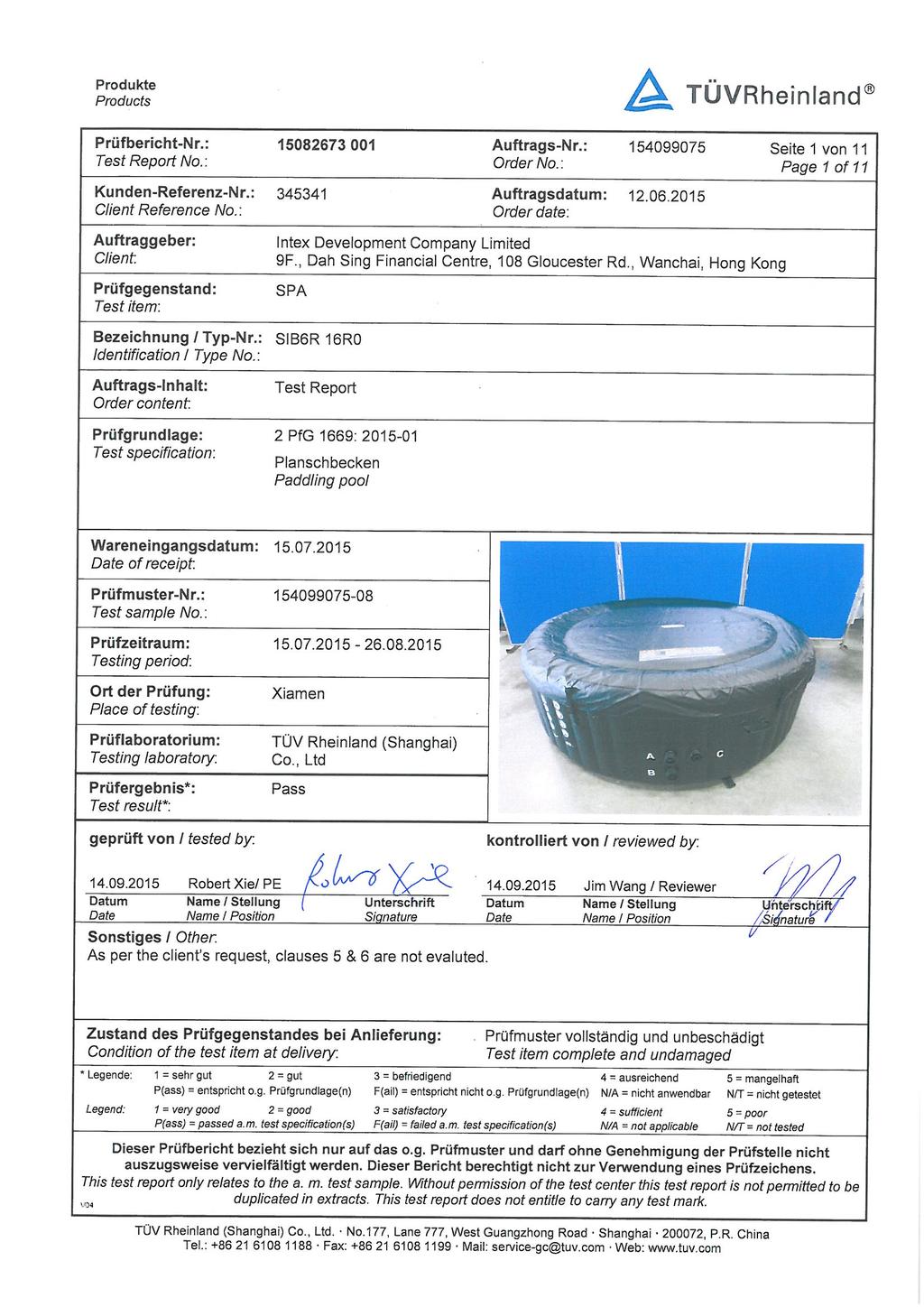
100
101 rodukte roducts rüfbericht-nr.: Test Report No.: Seite 2 von 11 age 2 of 11 Liste der verwendeten rüfmittel List of used test equipment rüfmittel Test equipment rüfmittel-nr. / ID-Nr. Equipment No. / ID-No. Nächste Kalibrierung Next calibration List of used test equipment could be traceable and provided separately upon request. Rev.:01

102 rodukte roducts rüfbericht-nr.: Test Report No.: Seite 3 von 11 age 3 of 11 roduktbeschreibung roduct description 1 roduktdetails roduct details Model No.: SIB6R 16R0 Capacity : 6 adults Rated pressure of air chamber: bar 2 Maße / Gewicht Dimensions / Weight 3 Bedienelemente Operating elements 4 Ausstattung / Zubehör Equipment / Accessories Inflated size: Height: Content: Net weight: / SA Cover 215cm (Outer) / 162cm 71cm 1098L 26.4kg w/o cover, 6.4kg for cover. 5 Verwendete Materialien Used materials 6 Sonstiges Other Overview (with cover) VC for the air chamber and cover. See page 1 and remarks in last page. Overview (without cover) Rev.:01
103 rodukte roducts rüfbericht-nr.: Test Report No.: Seite 4 von 11 age 4 of 11 Absatz 2 fg 1669: Messergebnisse - Bemerkungen Bewertung Clause Anforderungen - rüfungen / Requirements - Tests Measuring results - Remarks Evaluation 1 Anwendungsbereich Scope Diese rüfgrundlage gilt für demontierbare Kunststoff -lanschbecken und Schwimmbecken für den häuslichen Bereich, selbsttragend oder mit Gestell. This test specification applies to removable plastic - addling pools and swimming pools for domestic use, self-supporting or with frame. 2 Allgemeine Anforderungen General requirements lanschbecken und Zubehörteile Elektrokomponenten, Leitern, umpen etc. müssen den gültigen Normen und technischen Regeln entsprechen. addling pool and accessories electrical components, ladders, pumps, etc. must comply with the applicable standards and regulations. This is test report for mechanical safety test, not including chemical testing, LMFBG, Electric component standards. F N/T 3 Konstruktion Construction 3.1 Ecken und Kanten Edges and corners Die Ecken und Kanten mit denen der Benutzer in unmittelbaren Kontakt kommt müssen abgerundet oder gefast sein. Alle sonstigen Ecken und Kanten, die während der Benutzung erreichbar sind, müssen mit einem Radius von mindestens 2 mm abgerundet sein. The corners and edges where the user comes in direct contact, must be rounded or beveled. All other corners and edges that are accessible during use shall be rounded to a radius of at least 2 mm. No sharp corner or edge on the samples F N/T 3.2 Zugängliche Teile Accessible parts Alle anderen zugänglichen Teile, müssen so gestaltet sein, dass sie bei Körperkontakt durch den Benutzer für diesen keine Verletzungsgefahr darstellen. All other accessible parts must be designed so that if the user comes into contact with it no injury can happen. No mechanical injury could be caused from all the accessible parts. F N/T Rev.:01
104 rodukte roducts rüfbericht-nr.: Test Report No.: Seite 5 von 11 age 5 of 11 Absatz 2 fg 1669: Messergebnisse - Bemerkungen Bewertung Clause Anforderungen - rüfungen / Requirements - Tests Measuring results - Remarks Evaluation 3.3 Fingerfangstellen Finger entrapment Im gebrauchsfertig zusammengebauten Zustand dürfen in keiner Anordnung Öffnungen und Zwischenräume über 5 mm und unter 12 mm vorhanden sein, außer, wenn die Eindringtiefe weniger als 10 mm beträgt. Die Enden von rohrförmigen Bauteilen müssen abgedeckt bzw. verschlossen sein. Tube shaped components, openings and gaps which are accessible during usage must be covered. Testing with a testing finger diameter 5 mm or 12 mm from individual direction and a maximum force of 30 N and max. 10 mm depth. The ends of tube shaped components have to be covered 3.4 Hängenbleiben von Gliedmaßen Stucking from limb Innerhalb des Zugangsbereiche, mit Ausnahme von Teilen, die im normalen Gebrauch nicht erreichbar sind, dürfen keine zugänglichen Löcher, Zwischenräume und Öffnungen vorhanden sein, die eine größere Breite als 25 mm aufweisen und kleiner als 45 mm sind. In the access area, except areas which are not accessible during usage, no holes, gaps and openings are allowed with following dimensions: 25 to 45 mm Tube shaped components are covered with plug caps. Tested with testing finger, all the inlets or outlets will not trap finger. Test sample checked with positive results. F N/T F N/T 3.5 Hängen bleiben des Kopfes, des Halses und des Rumpfes Stucking from head, neck and body Innerhalb des Zugangsbereichs sind keine keilförmigen Öffnungen zulässig. Alle Löcher Zwischenräume oder Öffnungen innerhalb des Zugangsbereiches müssen entweder verhindern, daß die Kopfsonde des Typs 1 vollständig hindurchpasst oder müssen einen vollständigen Durchgang der Kopfsonde des Typs 2 zulassen, während sie den niedrigsten unkt der Öffnung berührt, wenn nach EN ,4 geprüft wird In the access area no v-shaped openings are allowed. All holes, gaps and clearances have to prohibit that either the head probe type 1 gets through or they must allow a full access of the head probe type 2 until you contact the lowest point in the opening according to EN ,4 No V- shape openings on the samples. F N/T Rev.:01
105 rodukte roducts rüfbericht-nr.: Test Report No.: Seite 6 von 11 age 6 of 11 Absatz 2 fg 1669: Messergebnisse - Bemerkungen Bewertung Clause Anforderungen - rüfungen / Requirements - Tests Measuring results - Remarks Evaluation 3.6 Scher- und Quetschstellen Shear- and squeezing points Scher- und Quetschstellen, die nur beim Aufstellen oder Zusammenfalten entstehen, sind zulässig, sofern davon ausgegangen werden kann, dass der Benutzer seine Bewegungen unter Kontrolle hat und in der Lage ist, die Krafteinwirkung bei Schmerzempfindung sofort zurückzunehmen. Die Kanten gegeneinander beweglicher Teile müssen jedoch gerundet sein, wenn sie Scher- und Quetschstellen beim Aufstellen oder Zusammenlegen erzeugen. Squeezing and Shearing points, which are during building up available, are acceptable as long the user can control it. All edges of which are moving against each other must rounded which can be a squeezing and shearing point during assembly or disassembly. No squeezing and shearing points accessible on the samples. F N/T 3.7 Seile, Schnüre und andere schmale Gewebe Ropes, cords and other narrow fabrics Seile Schnüre und andere schmale Gewebe (z. B. solche, die als Verbindungen benutzt werden) dürfen keine freie Länge von mehr ais 220 mm haben. Ropes, cord and other narrow textile (e.g. used as connections) must not have a longer free length than 220 mm 3.8 Schlaufen Loops Schlaufen dürfen kein größeres Umfangsmaß als 360 mm haben. Loops circumference must not be larger than 360 mm. 4 rüfungen Tests 4.1 Beckenhaut ool skin Bei Beschädigung der Haut, Schnittlänge ca. 3 bis 5 cm, darf diese nicht plötzlich versagen, platzen oder weiterreißen. If the skin of the pool get a cut of about 3 to 5 cm it must not fail immediately or go on tearing automatically. The straps end on the buckles fulfilled the test requirements. The circumference of Loops is less than 360mm. After cut with 5cm on the skin, the test sample did not fail immediately or go on tearing automatically. F N/T F N/T F N/T Rev.:01
106 rodukte roducts rüfbericht-nr.: Test Report No.: Seite 7 von 11 age 7 of 11 Absatz 2 fg 1669: Messergebnisse - Bemerkungen Bewertung Clause Anforderungen - rüfungen / Requirements - Tests Measuring results - Remarks Evaluation 4.2 Stützrohre und Verbindungselemente Support tubes and connectors aus Kunststoff müssen UV- und alterungsbeständig sein. Stützrohre und Verbindungselemente dürfen bei Bruch nicht splittern. Stützrohre und Verbindungs-elemente aus Metall müssen ausreichend gegen Korrosion geschützt sein. Rohre und Verbindungen, Rohre und ähnlich starre Teile: Die Enden von Rohren, rofilen, Hebeln und ähnlich starren Teilen, die über die Oberfläche herausragen, und die durch Beschaffenheit, Durchmesser oder Länge die Gefahr des Eindringes in die Haut bergen, müssen entschärft sein. Rohrenden müssen verschlossen sein. Support tubes and connecting elements made of plastic must be resistant against weathering and UV light. The tubes must have date until it can be used. The supporting tubes and connecting elements must not splitter during breakage. Support and connecting elements made of metel must be coated sufficiently against corrosion. Tubes and similar stiff components. The ends of tubes, profiles, lever and other similar stiff components, which octruct out of the surface and their dimensions or length can cause stiching into the skin must be duburred. Tubes must be plugged. 4.3 Festigkeit Strength Das Becken muss den mechanischen Beanspruchungen (hydrostatischer Druck) standhalten. Dies ist durch Berechnung oder rüfung nachzuweisen. Der Beckenrand muss einer vertikalen Belastung von 100 kg an ungünstigster Stelle standhalten. (Sitzen auf dem Rand) The pool must withstand mechanical stress (hydrostatic pressure). This is demonstrated by calculation or testing. The upper pool edge must resist a vertical load of 100 kg at the most unfavourable position. (e.g. sitting on the edge). Free standing swimming pool. No support tubes and connecting elements used. Tested with positive results. The test sample tested with sand with density 2 times of the water. No breakage and no damage. When tested with 100kg on the edge, no unsatisfactory findings found. F N/T F N/T Rev.:01
107 rodukte roducts rüfbericht-nr.: Test Report No.: Seite 8 von 11 age 8 of 11 Absatz 2 fg 1669: Messergebnisse - Bemerkungen Bewertung Clause Anforderungen - rüfungen / Requirements - Tests Measuring results - Remarks Evaluation 4.4 Luftkammern Air chambers rüfung der Festigkeit der Tragschlauchsysteme (Luftkammern) Die Festigkeit wird mit einem rüfzyklus nachgewiesen. Durchzuführen sind 50 Zyklen je Kammer des Tragschlauchsystemes in der Reihenfolge der Aufblasangabe (Herstellerangabe), danach folgt eine ause von 12 Stunden unter dem vom Hersteller angegebenen zulässigen Betriebsüberdruck. Anschließend werden weitere 25 Zyklen durchgeführt. Während der Zyklusprüfung darf kein Versagen der Nahtverbindung auftreten. rüfbedingungen: a) Normalklima b) um 10% erhöhter zulässiger Betriebsüberdruck aufgebracht in etwa 20 Minuten c) 5 Minuten Standzeit bei konstantem Überdruck d) 5 Minuten Ruhezeit im drucklosen Zustand Kammern sind separat zu prüfen, indem jeweils die 2. Kammer nach Erreichen des zulässigen Betriebsdruck zu verschließen ist. Tested with positive results as required. F N/T Testing of the stability of load bearing air chambers. The resistance of the air camber will be proven by a cycling test. The cycle works as follow: Inflate the pool according to the instruction up to the max. rated pressure for 50 times. Afterwards keep the pressure for 12 hours. The next 25 cycles work as follow: a.) normal climate b.) additional 10% increased pressure of the rated load c.) 5 minutes holding time d.) 5 minutes holding time in condition without pressure. Each chamber has to be checked separate, while every 2 nd chamber has to be loaded at the rated pressure. No fail of the seams is allowed. Rev.:01
108 rodukte roducts rüfbericht-nr.: Test Report No.: Seite 9 von 11 age 9 of 11 Absatz 2 fg 1669: Messergebnisse - Bemerkungen Bewertung Clause Anforderungen - rüfungen / Requirements - Tests Measuring results - Remarks Evaluation 4.5 rüfung der Füllgasundurchlässigkeit bei Luftkammern Examination of air loss of air chambers Die rüfung erfolgt im Anschluss an die Zyklenprüfung bei Normalklima. Das Becken wird nach Gebrauchsanweisung mit dem zulässigen Betriebsüberdruck aufgepumpt, verschlossen und 15 Minuten stehen lassen. Dann wird innerhalb einer Minute um 50% erhöht und verschlossen. Tested with positive results as required. F N/T Nachdem der Kammerdruck um 50% erhöht wurde, werden an der Stelle des größten Durchmessers 2 Markierungspunkte im Abstand von 100 mm aufgetragen. nach 12 Stunden darf der Abstand nicht kleiner sein als 100 mm. The test will be performed at normal climate after the cycling test. The pool has to be inflated according to the manual with the rated pressure. Then the pressure has to be kept for 15 minutes. Afterwards increases the pressure 50% and close the plugs. Apply 2 marks in the distance of 100mm at the biggest diameter. After 12 hours the distance between the 2 marks should not be smaller than 100mm. Rev.:01
109 rodukte roducts rüfbericht-nr.: Test Report No.: Seite 10 von 11 age 10 of 11 Absatz 2 fg 1669: Messergebnisse - Bemerkungen Bewertung Clause Anforderungen - rüfungen / Requirements - Tests Measuring results - Remarks Evaluation 5 Kennzeichnung (Typenschild) Marking Die rodukte sind dauerhaft mit mindestens den folgenden Angaben zu kennzeichnen: Name + Adresse des Herstellers / Inverkehrbringers Typbezeichnung Warnhinweise: ACHTUNG! - Lassen Sie ihr Kind nicht unbeaufsichtigt - Gefahr durch Ertrinken! - Nur für den Hausgebrauch und zur Verwendung im Freien! - Nicht springen! Nicht tauchen! - Nur auf ebenem, glatten Untergrund aufstellen! Werden die Hinweise in Form von iktogrammen aufgebracht, sind diese in der Gebrauchsanleitung zu wiederholen und vollständig zu erläutern. Not tested acc. to client s request. F N/T The products are permanently marked with at least the following information: Name + address of the manufacturer / Distributor type designation Warnings: ATTENTION! - Never leave your child unattended Risk of drowning! - Only for domestic use and for outdoor use! - Do not jump! Do not dive! - lace only on flat, smooth surfaces! If the information in the form of pictograms applied, these must be repeated in the instruction manual and to fully explain. Rev.:01
110 rodukte roducts rüfbericht-nr.: Test Report No.: Seite 11 von 11 age 11 of 11 Absatz 2 fg 1669: Messergebnisse - Bemerkungen Bewertung Clause Anforderungen - rüfungen / Requirements - Tests Measuring results - Remarks Evaluation 6 Gebrauchsanleitung User manual Das rodukt muss mit einer Gebrauchsanleitung in deutscher Sprache mit mindestens folgenden Angaben versehen sein: - Gerätetyp - Herstelleradresse - Montage - Handhabung - flege - Lagerung - Anwendungsbereich - Reparaturhinweise Warnhinweise: ACHTUNG! - Lassen Sie ihr Kind nicht unbeaufsichtigt - Gefahr durch Ertrinken! - Nur für den Hausgebrauch und zur Verwendung im Freien! - Nicht springen! Nicht tauchen! - Nur auf ebenem, glatten Untergrund aufstellen! The product must be provided with an owner's manual in German, stating at least: - Device type - Manufacturer's address - Installation - Handling - Care - Storage - Scope - Repair instructions warnings: ATTENTION! - Never leave your child unattended - Risk of drowning! - Only for domestic use and for Outdoor use! - Do not jump! Do not dive! - lace only on flat, smooth surfaces! Not tested acc. to client s request. F N/T Remark: This test report does not evidence compliance of the provided sample with the relevant standard but only with the referred tests. This test report documents the findings of examination conducted on the delivered test samples in page 3. This report only does not entitle the application to carry any safety mark on this or similar products. Further for sales or other application purposes of the tested product, any reference to TÜV Rheinland or a test through TÜV Rheinland is only permissible with prior written consent of TÜV Rheinland. - END - Rev.:01
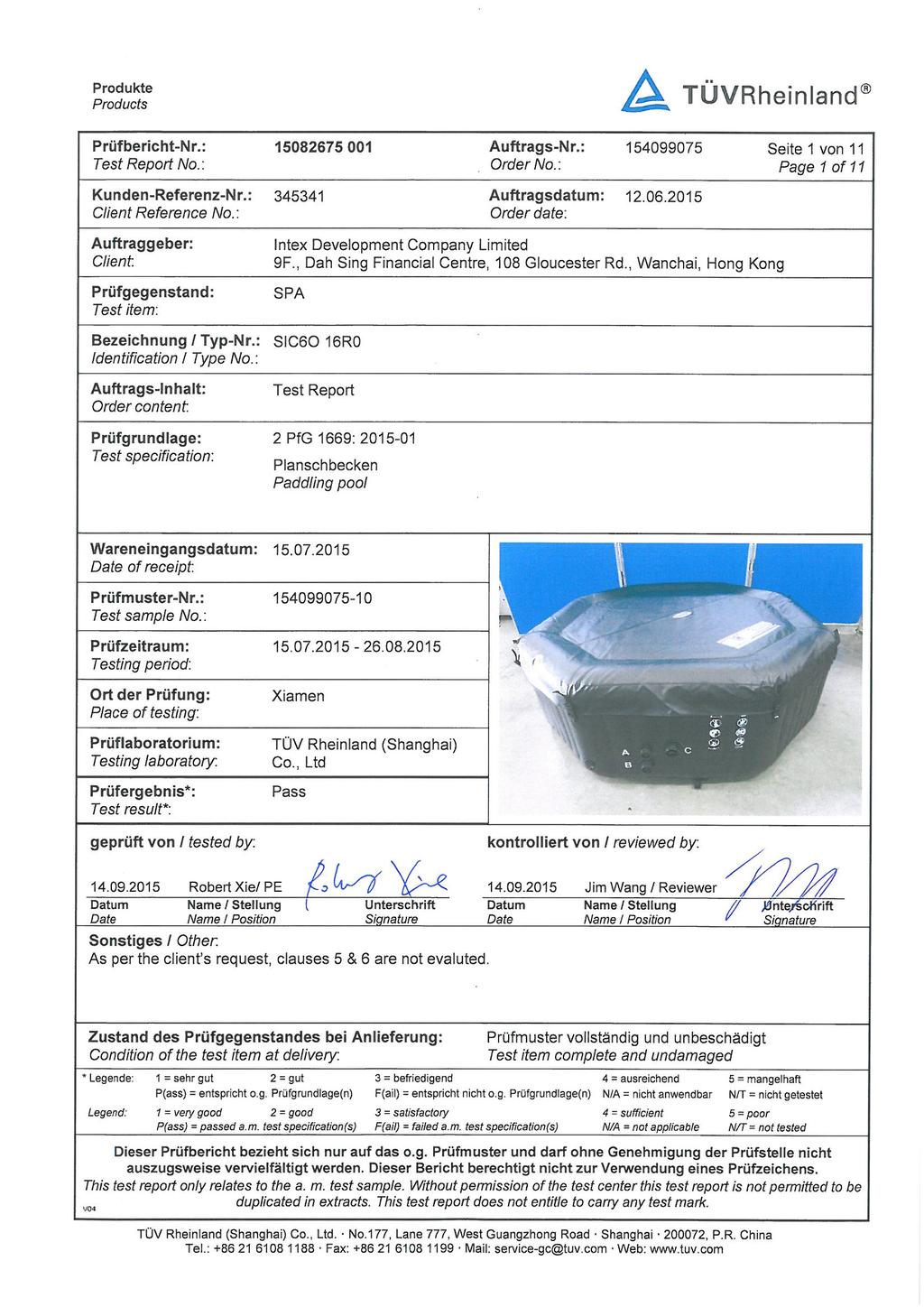
111
112 rodukte roducts rüfbericht-nr.: Test Report No.: Seite 2 von 11 age 2 of 11 Liste der verwendeten rüfmittel List of used test equipment rüfmittel Test equipment rüfmittel-nr. / ID-Nr. Equipment No. / ID-No. Nächste Kalibrierung Next calibration List of used test equipment could be traceable and provided separately upon request. Rev.:01

 / 166cm (Inner) 71cm 1098L 25.2kg w/o cover, 6.4kg for cover.")
113 rodukte roducts rüfbericht-nr.: Test Report No.: Seite 3 von 11 age 3 of 11 roduktbeschreibung roduct description 1 roduktdetails roduct details Model No.: SIC6O 16R0 Capacity : 6 adults Rated pressure of air chamber: bar 2 Maße / Gewicht Dimensions / Weight 3 Bedienelemente Operating elements 4 Ausstattung / Zubehör Equipment / Accessories Inflated size: Height: Content: Net weight: / SA Cover 216cm (Outer) / 166cm (Inner) 71cm 1098L 25.2kg w/o cover, 6.4kg for cover. 5 Verwendete Materialien Used materials 6 Sonstiges Other Overview (with cover) VC for the air chamber and cover. See page 1 and remarks in last page. Overview (without cover) Rev.:01
TEST REPORT IEC Safety of household and similar electrical appliances
 Test Report issued under the responsibility of: TEST REORT Safety of household and similar electrical appliances Report Number.... : 160100083SHA-001 Date of issue... : 2016-05-10 Total number of pages...
TEST REPORT IEC Safety of household and similar electrical appliances Part-2-41: Particular requirements for pumps
 Test Report issued under the responsibility of: TEST REORT Safety of household and similar electrical appliances art-2-41: articular requirements for pumps Report Number.... : ITD-14A0233HCS Date of issue...
Tested by (name + signature)... : see on page 1. Approved by (name + signature)... : see on page 1. Tested by (name + signature)...
... : see on page 1. Approved by (name + signature)... : see on page 1. Tested by (name + signature)...") age 2 of 101 Report No. 28225175 001 Testing procedure and testing location: CB Testing Laboratory: Testing location/ address... : TÜV Rheinland InterCert Kft H-1132 Budapest, Váci út 48/A-B., Hungary
age 2 of 101 Report No. 28225175 001 Testing procedure and testing location: CB Testing Laboratory: Testing location/ address... : TÜV Rheinland InterCert Kft H-1132 Budapest, Váci út 48/A-B., Hungary
TEST REPORT IEC Safety of household and similar electrical appliances
 Test Report issued under the responsibility of: TEST REORT Safety of household and similar electrical appliances Report Number....: T211-0590/12 Date of issue...: 2012-11-22 Total number of pages... 93
TEST REPORT IEC Safety of household and similar electrical appliances Part 2: Particular requirements for massage appliance
 Test Report issued under the responsibility of: SGS- CSTC TEST REORT Safety of household and similar electrical appliances art 2: articular requirements for massage appliance Report Reference No....: GZES100800181503
NCB TÜV SÜD PSB Pte Ltd 1 Science Park Drive, Singapore Singapore
 age 1 of 100 Test Report issued under the responsibility of: NCB TÜV SÜD SB te Ltd 1 Science ark Drive, 118221 Singapore Singapore TEST REORT Safety of household and similar electrical appliances 删除的内容
TEST REPORT ON THE SAFETY OF ELECTRICAL EQUIPMENT FOR PRODUCT INNOVATORS LTD ON A INFRARED TANKLESS HOT WATER SYSTEM
 TEST REPORT ON THE SAFETY OF ELECTRICAL EQUIPMENT FOR PRODUCT INNOVATORS LTD ON A INFRARED TANKLESS HOT WATER SYSTEM MODEL: IR 3000/4000/6000/8000 RH 3500/4500/6500/8500 REPORT NO. TRA-015720-34-00A Test
TEST REPORT EN Household and similar electrical appliances - Safety Part 1: General requirements
 age 1 of 105 Test Report issued under the responsibility of: AN LAB CO d.o.o. Trgovacka 79 Belgrade 11030 Serbia TEST REORT EN 60335-1 Household and similar electrical appliances - Safety art 1: General
TEST REPORT IEC Safety of household and similar electrical appliances
 age 1 of 76 TEST REORT Safety of household and similar electrical appliances Report Number.... : 311280 Date of issue... : 11/11/2016 Total number of pages... : 76 Applicant s name... : Address... : Monotile
TEST REPORT IEC Safety of household and similar electrical appliances
 Test Report issued under the responsibility of: TEST REORT Safety of household and similar electrical appliances Report Number.... : 27113131 001 Date of issue... : 22.10.2013 Total number of pages...
TEST REPORT EN Household and similar electrical appliances. Safety. General requirements
 TEST REORT EN 60335-1 Household and similar electrical appliances. Safety. General requirements Report Reference No.... : 08.01.16.0258.01 Compiled by (+ signature)... : Approved by (+ signature)... :
Safety of household and similar electrical appliances
 Test Report issued under the responsibility of: TEST REORT Safety of household and similar electrical appliances Report Number....: GZES171101935301 Date of issue...: 2018-03-16 Total number of pages...:
CERTIFICATE OF APPROVAL
 Certificate Number: TUV16069EA CERTIFICATE OF AROVAL.. TUVRheinland Authorised marking: TUV16069EA This is to certify that TOV Rhein/and Australia ty Ltd as accredited by JAS-ANZ in accordance with /SOI/EC
TEST REPORT IEC Safety of household and similar electrical appliances Part 2 : Particular requirements for fans Report Reference No.
 Test Report issued under the responsibility of: TEST REORT Safety of household and similar electrical appliances art 2 : articular requirements for fans Report Reference No...: 28210014 001 Date of issue...:
TEST REPORT IEC/EN Safety of household and similar electrical appliances
 age 1 of 69 TEST REORT Safety of household and similar electrical appliances Report Number.... : Complied by (+ signature)... : Gyewan, Kim Approved by (+ signature)... : Kangsun, Lee Date of issue...
TEST REPORT IEC Safety of household and similar electrical appliances Part 2 : Particular requirements for fans
 Test Report issued under the responsibility of: SGS Fimko Ltd. TEST REORT Safety of household and similar electrical appliances art 2 : articular requirements for fans Report Number.... : GZES151101346201
re : CERTIFICATE OF APPROVAL TUV15998EA Certificate Number:
 Certificate Number: TUV15998EA CERTIFICATE OF AROVAL.. TUVRheinland Authorised marking: TUV15998EA This is to certify that TOV Rhein/and Australia ty Ltd as accredited by JAS-ANZ in accordance with /SOI/EC
HISTORICAL OF SAMPLE RECEIVED
 TEST REORT N : LMO-14SE1873DTS HISTORICAL OF SAMLE RECEIVED LCIE CHI RECORDED N DETAIL OF THE SAMLE SECIAL REMARKS -- Original sample None COY OF RATING LATE: Other marking plates are same as above except
TEST REPORT IEC/EN Safety of household and similar electrical appliances Part 2: Particular requirements for portable heating tools
 TEST REORT IEC/E 60335-2-45 Safety of household and similar electrical appliances art 2: articular requirements for portable heating tools Report umber....: DE113487 Date of issue...: 2015-06-09 Total
Report No.: F690501/RF-SAF Testing location:
 age 2 of 81 Summary of testing: The tested samples comply with the requirement of the test specification Tests performed (name of test and test clause): All test Testing location: Copy of marking plate
TEST REPORT IEC Safety of household and similar electrical appliances Part 2: Particular requirements for room heaters
 Test Report issued under the responsibility of: TEST REORT Safety of household and similar electrical appliances art 2: articular requirements for room heaters Report Number.... : 21140671 009 Date of
ZH0505-GR-HT N/A IEC60335_2_9H LCIE
 Test Report issued under the responsibility of TEST REORT Safety of household and similar electrical appliances art 2: articular requirements for grills, toasters and similar cooking appliances Report
INSTITUTE OF TESTING AND CERTIFICATION (INDIA) PVT. LTD. COPY OF MARKING PLATE
 PVT. LTD. COPY OF MARKING PLATE") INSTITUTE OF TESTING AND CERTIFICATION (INDIA) VT. LTD. COY OF MARKING LATE Report No.-ITC/TEST/NN/1508/01 age 3 of 51 (INDIA) VT. LTD. 6 Classification Appliances shall be of one of the following 6.1
INSTITUTE OF TESTING AND CERTIFICATION (INDIA) VT. LTD. COY OF MARKING LATE Report No.-ITC/TEST/NN/1508/01 age 3 of 51 (INDIA) VT. LTD. 6 Classification Appliances shall be of one of the following 6.1
TEST REPORT IEC Safety of household and similar electrical appliances Part 2 : Particular requirements for fans
 age 1 of 114 Report o.: STUESO017022702211HS TEST REORT Safety of household and similar electrical appliances art 2 : articular requirements for fans Report umber.... : STUESO017022702211HS Date of issue...
HW C.K. Park. H.S. Choi. KTC(Korea Testing Certification)
") Korea Testing Certification TEST REORT Household and similar electrical appliances - Safety art 2-17: articular requirements for blankets, pads and similar flexible heating appliances Report Reference
Korea Testing Certification TEST REORT Household and similar electrical appliances - Safety art 2-17: articular requirements for blankets, pads and similar flexible heating appliances Report Reference
Test Report issued under the responsibility of: Report Number... : Date of issue... : Total number of pages...
 Test Report issued under the responsibility of: TEST REORT Household and similar electrical appliances - Safety art 2-17: articular requirements for blankets, pads and similar flexible heating appliances
TEST REPORT EN Safety of household and similar electrical appliances
 age 1 of 54 TEST REORT EN 60335-1 Safety of household and similar electrical appliances Report Reference No.... : Complied by (+ signature)... : Approved by (+ signature)... : TK-CL110016 Byung il, Lee
TEST REPORT IEC Safety of household and similar electrical appliances Part 2: Particular requirements for room heaters
 SHEZHE LCS COMLIACE TESTIG LABORATORY LTD REORT O.: LCS170407067AS Report umber.... : TEST REORT IEC 60335-2-30 Safety of household and similar electrical appliances art 2: articular requirements for room
EC Declaration of Conformity According to Low Voltage Directive 2006/95/EC
 EC Declaration of Conformity According to Low Voltage Directive 2006/95/EC Manufacturer's Name: Dae Yeon Co., Ltd. Manufacturer's Address: San 31, Nokchon-ri, hwado-eup, Namyangju-si, Gyeonggi-do, Republic
Test Report issued under the responsibility of: Report Reference No... : Date of issue... : Total number of pages...
 Test Report issued under the responsibility of: TEST REORT IEC/EN 60 335-2-64 Safety of household and similar electrical appliances art 2-64: articular requirements for commercial electric kitchen machines
BS EN : A2:2015 used in conjunction with BS EN : A11:2014 and BS EN 62233:2008
 Test Report Report No 8587907 Client Regal Care Shower Trays Ltd. Regal House, Smithy Lane, Scarisbrick, L40 8HN Authority & date SMO: 8587907, Date: August 9, 2016 Items tested ARESF Body Dryer with alternative
TEST REPORT EN :2012/AC:2014 Household and similar electrical appliances Safety Part 1:General requirements
 age 1 of 54 Ref. o: SCC(15)-40712A-3-10- LVD TEST REORT E 60335-1:2012/AC:2014 Household and similar electrical appliances Safety art 1:General requirements Report Reference o....: SCC(15)-40712A-3-10-
Test Report. Hotpoint Fridge Freezer Model FF175B
 Davy Avenue, Knowlhill Milton Keynes MK5 8NL, United Kingdom Telephone: +44 1908 85 7777 www.intertek.com age 1 of 95 Test Report Hotpoint Fridge Freezer Model FF175B Report No. 103250895MKS-001 Commercial-in-confidence
KALDEWEI SKIN TOUCH WELLNESSPRODUKT
 KALDEWEI SKIN TOUCH WELLNESSRODUKT GS-Zertifikat für roduktsicherheit. SKIN TOUCH wurde durch den TÜV Rheinland untersucht. Die Untersuchung ergab, dass das SKIN TOUCH System für Badewannen den gestellten
APPLICATION FOR LOW VOLTAGE DIRECTIVE On Behalf of BestSub Technologies Co Ltd 3D Vacuum Sublimation Machine Model: SZM3D
 ALICATIO FOR LOW VOLTAGE DIRECTIVE On Behalf of BestSub Technologies Co Ltd 3D Vacuum Sublimation Machine Model: SZM3D repared For : BestSub Technologies Co Ltd Rm810 Exchange Square, o.268, Dongfeng Zhong
IECEx TEST REPORT IEC Explosive atmospheres Part 0: Equipment General requirements
 ExTR Reference Number...: ExTR Free Reference Number...: 223531 Compiled by + signature (ExTL)...: Reviewed by + signature (ExTL)...: NO/NEM/ExTR12.0018/00 Stig André Norheim Arne Hortman Date of issue...:
Page 2 of 51. Copy of the marking plate: Refrigerant: R22
 12011921 001 age 2 of 51 Copy of the marking plate: Refrigerant: R22 ELECTRA MODEL:K-36SH ROD O.: Fuse: 25 A(G) TYE: COS =0.95 380-400V~ 50Hz I20 Rev.A Dehumidification: 4.0 l/h R22 rated: 3120 W S: 4.4Ma
COSφ= V~ 50Hz IP20 Rev.A DehumiDification:1.0 l/h R22: Prated:45W PS: 4.4MPa Ps: 0.6MPa Temp.Class: T1 Weight:19kg
 12011245 001 age 2 of 60 Copy of the marking plate: Refrigerant: R22 ELECTRA MODEL: XD9 RODO.: Fuse: 10A(G) TYE: COSφ=0.95 220-230V~ 50Hz I20 Rev.A DehumiDification:1.0 l/h R22: rated:45w S: 4.4Ma s: 0.6Ma
Modified Clauses of EN /A1:2004
 age 2 of 19 Report No.: 17003895 002 7. MARKING AND INSTRUCTIONS Modified Clauses of EN 60335-1/A1:2004 7.1 Symbol IEC 60417-5036, for the enclosure of electrically-operated water valves in external hosesets
TEST REPORT IEC Safety of laser products - Part 1: Equipment classification and requirements
 SHENZHEN LCS COMLIANCE TESTING LABORATORY LTD REORT NO.: LCS1611293204S TEST REORT Safety of laser products - art 1: Equipment classification and requirements Report Number.... : LCS1611293204S Date of
ZHEJIANG MAXGE ELECTRIC TECHNOLOGY CO., LTD. Address...:
 Test Report issued under the responsibility of: TEST REORT IEC 61008-1 Residual current operated circuit-breakers without integral overcurrent protection for household and similar uses (RCCBs) art 1: General
APPLICATION FOR LOW VOLTAGE DIRECTIVE On Behalf of. Pest repeller Model: AN-A339
 age 1 of 71 Report o. 201404684S ALICATIO FOR LOW VOLTAGE DIRECTIVE On Behalf of Shenzhen Aosion hotoelectricity Co., Ltd. est repeller Model: A-A339 repared For : Shenzhen Aosion hotoelectricity Co.,
Oldal/ Page 2 / 2 Test report No.: Submersible Pump Test item description... :
 www.meei.hu Oldal/ age 2 / 2 Test report No.: 28205370 004 Test item description... : Trade Mark... : Submersible ump ELUMS Manufacturer... : ELUMS Kft. 4900 Fehérgyarmat, Vasvári ál u. 65. Model/Type
TEST REPORT IEC Safety of laser products - Part 1: Equipment classification and requirements
 Test Report issued under the responsibility of: TEST REPORT IEC 60825-1 Safety of laser products - Part 1: Equipment classification and requirements Report Number.... : 102254161MPK-001L Date of issue...
Page 1 of 90 Report No. J0908CE
 age 1 of 90 Report o. J0908CE8888-0324 TEST REORT IEC/E 60 335-2-40 Household and similar electrical appliances Safety art 2-40: articular requirements for electrical heat pumps,air conditioners and dehumidifiers
TEST REPORT IEC Safety of laser products - Part 1: Equipment classification and requirements. TÜV Rheinland Shanghai Co., Ltd.
 Test Report issued under the responsibility of: TEST REORT IEC 60825-1 Safety of laser products - art 1: Equipment classification and requirements Report Number.... : 50089797 001 Date of issue... : 2017.07.25
ENEC NO2187. Nemko hereby grants the following manufacturer as licensee the right to affix this ENEC mark on the product(s) specified below.
 specified below.") ENEC NO2187 age 1/1 Order No. 135699 Licence for use of the here shown ENEC conformity mark : Based on: Agreement on the use of a commonly agreed Mark on Conformity for equipment complying with European
ENEC NO2187 age 1/1 Order No. 135699 Licence for use of the here shown ENEC conformity mark : Based on: Agreement on the use of a commonly agreed Mark on Conformity for equipment complying with European
TEST REPORT IEC , 2 nd Edition Part 1: Equipment classification and requirements
 Test Report issued under the responsibility of: TEST REORT IEC 60825-1, 2 nd Edition art 1: Equipment classification and requirements Report Reference No....: EFSH15041135-IE-01-L01 Date of issue...: May
K-SQ13, KA-SQ13, K-SQ14, KA-SQ14, KO-SQ13, KOA-SQ13, KO-SQ14, KOA-SQ14, K-SQ13C, KA-SQ13C, K-SQ14C, KA- SQ14C, KO-SQ13C, KOA-SQ13C, KO-SQ14C,
 age 2 of 14 Model/Type reference...: Ratings...: K-SQ13, KA-SQ13, K-SQ14, KA-SQ14, KO-SQ13, KOA-SQ13, KO-SQ14, KOA-SQ14, K-SQ13C, KA-SQ13C, K-SQ14C, KA- SQ14C, KO-SQ13C, KOA-SQ13C, KO-SQ14C, KOA-SQ14C,
IEC60601_1J. Medical electrical equipment Part 1: General requirements for basic safety and essential performance
 Page 1 of 157 Report No.: E309264-D1009-1-CB CB - IEC REPORT: Test Report issued under the responsibility of: IEC 60601-1 Medical electrical equipment Part 1: General requirements for basic safety and
STANDARDS UPDATE NOTICE (SUN) ISSUED: August 23, 2017
 ISSUED: August 23, 2017") STANDARDS UPDATE NOTICE (SUN) ISSUED: August 23, 2017 STANDARD INFORMATION Standard Number: UL 412 Standard Name: Refrigeration Unit Coolers Standard Edition and Issue Date: 5 th Edition Dated August 22,
STANDARDS UPDATE NOTICE (SUN) ISSUED: August 23, 2017 STANDARD INFORMATION Standard Number: UL 412 Standard Name: Refrigeration Unit Coolers Standard Edition and Issue Date: 5 th Edition Dated August 22,
TEST REPORT EN :2002+A1:2004+A11:2004+A2:2006+A12:2006 EN : 2003+A1:2008
 TEST REORT E 60335-1:2002+A1:2004+A11:2004+A2:2006+A12:2006 E 60335-2-23: 2003+A1:2008 Safety of household and similar electrical appliances art 2-23: articular requirements for appliances for skin or
Amendment to Test Report
 - Page 1 of 5 - Test Report issued under the responsibility of: Amendment to Test Report www.nemko.com This Amendment is valid only together with the main Test Report Report o....: 221968 Main Report o...:
KINGDOM OF SAUDI ARABIA SASO/IEC /2012 SASO IEC
 SASO IEC 60335-2-6 HOUSEHOLD AND SIMILAR ELECTRICAL APPLIANCES- SAFETY PART 2-6: PARTICULAR REQUIREMENTS FOR STATIONARY COOKING RANGES, HOPS, OVENS AND SIMILAR APPLIANCES Date of SASO Board of Directors
INTERNATIONAL STANDARD
 INTERNATIONAL STANDARD IEC 60335-2-6 Fifth edition 2002-07 Household and similar electrical appliances Safety Part 2-6: Particular requirement for cooking ranges, hobs, ovens and similar appliances Appareils
IEC60601_1K. Medical electrical equipment Part 1: General requirements for basic safety and essential performance
 Page 1 of 165 Report No.: E309264-D1028-1/A0/C0-UL Test Report issued under the responsibility of: IEC 60601-1 Medical electrical equipment Part 1: General requirements for basic safety and essential performance
Test Report issued under the responsibility of:
 Test Report issued under the responsibility of: NCB TÜ V SÜ D PSB Pte Ltd 1 Science Park Drive, Singapore 118221 TEST REPORT IEC 61347-2-13 Part 2: Particular requirements: Section Thirteen d.c. or a.c.
FINAL ATEX REPORT ON EQUIPMENT FOR USE IN POTENTIALLY EXPLOSIVE ATMOSPHERES FOR GOLDEN PROMISE EQUIPMENT INC. FLOW MONITOR, GPE3000 SERIES,
 FINAL ATEX REPORT ON EQUIPMENT FOR USE IN POTENTIALLY EXPLOSIVE ATMOSPHERES FOR GOLDEN PROMISE EQUIPMENT INC. ON FLOW MONITOR, GPE3000 SERIES, REPORT NO. TRA-015825-33-00A ExTR Reference No. TRA-015825-33-00A
INTERNATIONAL STANDARD NORME INTERNATIONALE
 IEC 62031 INTERNATIONAL STANDARD NORME INTERNATIONALE Edition 1.0 2008-01 2 62031 IEC:2008 CONTENTS FOREWORD...3 INTRODUCTION...5 1 Scope...6 2 Normative references...6 3 Terms and definitions...7 4 General
INTERNATIONAL STANDARD
 INTERNATIONAL STANDARD IEC 60335-2-30 Edition 5.0 2009-11 Household and similar electrical appliances Safety Part 2-30: Particular requirements for room heaters INTERNATIONAL ELECTROTECHNICAL COMMISSION
Test report. ifesesws^ Date: Number: T /17 Project file: C Pages: Product: Fixed general purpose LED luminaire
 Sl/Q ifesesws^ SLOVENSKA AKREDITACIJA SIST EN ISO/ 1EC 17025 L-009 Test report Number: roduct: roject file: Fixed general purpose LED luminaire Date: ages: C20170767 2017-04-26 12 Type reference: LA-FL/G-xxW-xxxxK-Rxxx/xxx-(D10kGy)
AS/NZS :2003 Luminaires - Part 1: General requirements and tests
 Menu Home About this portal Latest updates Print Save Email Resource detail Citations AS/NZS 60598.1:2003 Luminaires - Part 1: General requirements and tests Table of Contents View on Information Provider
Rules for Classification and Construction Additional Rules and Guidelines
 VI Rules for Classification and Construction Additional Rules and Guidelines 7 Guidelines for the Performance of Type Approvals 7 Test Requirements for Statical Converters with Semi-Conductors Edition
INTERNATIONAL STANDARD
 INTERNATIONAL STANDARD IEC 60335-2-6 Fifth edition 2002-07 Household and similar electrical appliances Safety Part 2-6: Particular requirements for stationary cooking ranges, hobs, ovens and similar appliances
INTERNATIONAL STANDARD
 INTERNATIONAL STANDARD IEC 62052-11 First edition 2003-02 Electricity metering equipment (AC) General requirements, tests and test conditions Part 11: Metering equipment This English-language version is
TECHNICAL REPORT IEC TR General testing procedures for medical electrical equipment. Edition
 TECHNICAL REPORT IEC TR 62354 Edition 3.0 2014-09 General testing procedures for medical electrical equipment INTERNATIONAL ELECTROTECHNICAL COMMISSION PRICE CODE XH ICS 11.040 ISBN 978-2-8322-1856-3 Warning!
TEST REPORT IEC MEDICAL ELECTRICAL EQUIPMENT
 Test Report issued under the responsibility of: TEST REORT MEDICAL ELECTRICAL EQUIMENT art 1-11: General requirements for basic safety and essential performance Collateral Standard: Requirements for medical
INTERNATIONAL STANDARD
 INTERNATIONAL STANDARD IEC 60335-2-41 Edition 3.1 2004-03 Edition 3:2002 consolidated with amendment 1:2004 Household and similar electrical appliances Safety Part 2-41: Particular requirements for pumps
3KW ELECTRIC FAN HEATER
 3KW ELECTRIC FAN HEATER MODEL NO: DEVIL 7003 PART NO: 6935452 OPERATION & MAINTENANCE INSTRUCTIONS LS0615 INTRODUCTION Thank you for purchasing this CLARKE product. Before attempting to use this product,
Contact Details. Please note that some of the contact details on this PDF document may not be current.
 Contact Details Please note that some of the contact details on this PDF document may not be current. Please use the following details if you need to contact us: Telephone: 0844 879 3588 Email: customer.services@gdcgroup.co.uk
RE-PR3-E-27 3-Phase Panel Mount 27kW
 Page 1 of 6 RE-PR3-E-27 3-Phase Panel Mount 27kW Features: Benefits: 0-10Vdc, 0-5Vdc, 4-20mA or manual via potentiometer control input Over temperature protection with auto reset Enclosed panel mounting
INTERNATIONAL STANDARD
 INTERNATIONAL STANDARD IEC 62040-1-2 First edition 2002-08 Uninterruptible power systems (UPS) Part 1-2: General and safety requirements for UPS used in restricted access locations Alimentations sans interruption
16 Stand Fan with Remote Control Model No: FS3-40R-30
 16 Stand Fan with Remote Control Model No: FS3-40R-30 FEATURES Remote Control 3 Speed Settings 4 Hour Auto-off Timer Oscillation LED Display Panel Adjustable Height Adjustable Tilt Head Whisper Quiet Operation
IEC60601_1J. Medical electrical equipment Part 1: General requirements for basic safety and essential performance
 Page 1 of 170 Report No.: E309264-D1021-1/A1/C0-UL IEC REPORT: Test Report issued under the responsibility of: IEC 60601-1 Medical electrical equipment Part 1: General requirements for basic safety and
Table of Contents FOREWORD... 3 INTRODUCTION SCOPE NORMATIVE REFERENCES DEFINITIONS AND ABBREVIATIONS REQUIREMENTS...
 TITLE SPECIFICATION FOR PHOTOELECTRIC CONTROL UNITS (PECUs) REFERENCE REV DATE: JUNE 2017 PAGE: 1 OF 16 REVISION DATE: Table of Contents FOREWORD... 3 INTRODUCTION... 4 1 SCOPE... 4 2 NORMATIVE REFERENCES...
PAKISTAN STANDARD LED MODULES FOR GENERAL LIGHTING (SAFETY SPECIFICATIONS) PS: _5211/2017 ICS:
 PS: _5211/2017 ICS:") PS: _5211/2017 ICS: 29.140.99 PAKISTAN STANDARD LED MODULES FOR GENERAL LIGHTING (SAFETY SPECIFICATIONS) (All Rights Reserved) PAKISTAN STANDARDS AND QUALITY CONTROL AUTHORITY, STANDARDS DEVELOPMENT CENTRE,
PS: _5211/2017 ICS: 29.140.99 PAKISTAN STANDARD LED MODULES FOR GENERAL LIGHTING (SAFETY SPECIFICATIONS) (All Rights Reserved) PAKISTAN STANDARDS AND QUALITY CONTROL AUTHORITY, STANDARDS DEVELOPMENT CENTRE,
Lloyd s Register Type Approval System Test Specification Number 3
 Working together for a safer world Lloyd s Register Type Approval System Test Specification Number 3 July 2015 Performance Test Specification for Equipment to be used in Marine Applications: Electric Cables
Report reference No...: 10TH0052_AS4777_+_ISR_3 Tested by (printed name and signature)...: Urs Seifert. Approved by (printed name and signature)...
...: Urs Seifert. Approved by (printed name and signature)...") TEST REORT AS 4777.2:2005 and AS 4777.3:2005 with additional deviations for Israel Grid connection of energy systems via inverters Grid protection requirements Report reference No...: 10TH0052_AS4777_+_ISR_3
TEST REORT AS 4777.2:2005 and AS 4777.3:2005 with additional deviations for Israel Grid connection of energy systems via inverters Grid protection requirements Report reference No...: 10TH0052_AS4777_+_ISR_3
General safety precautions English
 English 1 1 1.1 About the documentation The original documentation is written in English. All other languages are translations. The precautions described in this document cover very important topics, follow
TC 61. Technical Committee 61 SAFETY OF HOUSEHOLD AND SIMILAR ELECTRICAL APPLIANCES
 Technical Committee 61 SAFETY OF HOUSEHOLD AND SIMILAR ELECTRICAL APPLIANCES Ensuring performance and safety of household electrical appliances in industrializing countries Seattle, Washington, USA: 2010-13-10
18 INCHES, OSCILLATING STAND FAN
 To Buy: Contact Sylvane at 800-934-9194 or visit www.sylvane.com For Product Support: Contact Soleus Air at (888) 876-5387 18 INCHES, OSCILLATING STAND FAN OWNER S MANUAL Model # FSM-45 PLEASE READ AND
INTERNATIONAL STANDARD
 INTERNATIONAL STANDARD IEC 60335-2-69 Edition 3.1 2005-01 Edition 3:2002 consolidated with amendment 1:2004 Household and similar electrical appliances Safety Part 2-69: Particular requirements for wet
40cm Pedestal Fan with Remote Control
 Instruction Manual 40cm Pedestal Fan with Remote Control Model: HF40BRG READ AND SAVE THESE INSTRUCTIONS Please read and follow the instructions in this user manual even if you feel you are familiar with
STANDARDS UPDATE NOTICE (SUN) ISSUED: March 2, 2018
 ISSUED: March 2, 2018") STANDARDS UPDATE NOTICE (SUN) ISSUED: March 2, 2018 STANDARD INFORMATION Standard Number: UL 1082 Standard Name: Standard for Household Electronic Coffee Makers and Brewing-Type Appliances Standard Edition
STANDARDS UPDATE NOTICE (SUN) ISSUED: March 2, 2018 STANDARD INFORMATION Standard Number: UL 1082 Standard Name: Standard for Household Electronic Coffee Makers and Brewing-Type Appliances Standard Edition
Electrical Safety Requirements
 Electrical Safety Requirements Purpose This document defines the minimum required control measures to reduce the risk of injury or illness related to electricity. Scope Applicable to all Coca-Cola system
AS/NZS IEC :2013
 AS/NZS IEC 61347.2.13:2013 (IEC 61347-2-13, Ed.1.0 2006, MOD) Australian/New Zealand Standard Lamp controlgear Part 2.13: Particular requirements for d.c. or a.c. supplied electronic controlgear for LED
INTERNATIONAL STANDARD
 INTERNATIONAL STANDARD IEC 60044-7 First edition 1999-12 Instrument transformers Part 7: Electronic voltage transformers This English-language version is derived from the original bilingual publication
INTERNATIONAL STANDARD
 INTERNATIONAL STANDARD IEC 60335-2-3 Edition 5.1 2005-01 Edition 5:2002 consolidated with amendment 1:2004 Household and similar electrical appliances Safety Part 2-3: Particular requirements for electric
General safety precautions English
 English A min (m 2 ) 550 530 540 510 520 490 500 470 480 450 460 430 440 410 420 390 400 370 380 350 360 330 340 310 320 290 300 270 280 250 260 230 240 210 220 190 200 170 180 150 160 130 140 110 120
General safety precautions English
 English A min (m 2 ) 550 530 540 510 520 490 500 470 480 450 460 430 440 410 420 390 400 370 380 350 360 330 340 310 320 290 300 270 280 250 260 230 240 210 220 190 200 170 180 150 160 130 140 110 120
Operating instructions Safety-monitoring module SRB 302X3. 1. About this document. Content
 8 Appendix 8.1 Wiring examples...4 8.2 Start configuration...4 8.3 Sensor configuration...4 8.4 Actuator configuration...5 Operating instructions.............pages 1 to 6 Original 9 EU Declaration of conformity
INTERNATIONAL STANDARD
 INTERNATIONAL STANDARD IEC 60335-1 Edition 4.1 2004-07 Edition 4:2001 consolidated with amendment 1:2004 Household and similar electrical appliances Safety Part 1: General requirements This English-language
General safety precautions English
 English 1 1 1.1 About the documentation The original documentation is written in English. All other languages are translations. The precautions described in this document cover very important topics, follow
Model No.: VS806-6N ( ) V~ 50/60Hz LED 6x4W
 V~ 50/60Hz LED 6x4W") Reference o.:wtf13f1210249r1s age 2 of 10 Test item description... : Trade Mark... : --- Model/Type reference... : Ratings... : Copy of marking plate: Ceiling Lamp VS806-6(180.003590); VS806-6(180.003591),
Reference o.:wtf13f1210249r1s age 2 of 10 Test item description... : Trade Mark... : --- Model/Type reference... : Ratings... : Copy of marking plate: Ceiling Lamp VS806-6(180.003590); VS806-6(180.003591),
INTERNATIONAL STANDARD
 INTERNATIONAL STANDARD IEC 60335-2-15 Fifth edition 2002-07 Household and similar electrical appliances Safety Part 2-15: Particular requirements for appliances for heating liquids Appareils électrodomestiques
5KW ELECTRIC FAN HEATER
 5KW ELECTRIC FAN HEATER MODEL NO: DEVIL 7005 PART NO: 6935452 OPERATION & MAINTENANCE INSTRUCTIONS LS0615 INTRODUCTION Thank you for purchasing this CLARKE product. Before attempting to use this product,
General safety precautions English
 English 1 1 Units are marked with the following symbol: 1.1 About the documentation The original documentation is written in English. All other languages are translations. The precautions described in
Cooker Hood LA-72-CAN.
 Cooker Hood LA-72-CAN EN www.luxairhoods.com WARNINGS Safety This equipment can be used by children aged 8 or more, people with physical, mental and sensory disabilities or inexperienced users it they
Girona. Operating Instructions. Glass Panel Heaters. Models: GFP050 W/B GFP075 W/B GFP100 W/B GFP150 W/B GFP200 W/B. A world of expertise
 A world of expertise Operating Instructions These instructions should be read carefully and retained for future use. Note also the information presented on the appliance. Girona Glass Panel Heaters Models:
INTERNATIONAL STANDARD
 INTERNATIONAL STANDARD IEC 60335-2-17 Second edition 2002-10 Household and similar electrical appliances Safety Part 2-17: Particular requirements for blankets, pads and similar flexible heating appliances