Oldal/ Page 2 / 2 Test report No.: Submersible Pump Test item description... :
|
|
|
- Brice Patrick
- 6 years ago
- Views:
Transcription

1
2 Oldal/ age 2 / 2 Test report No.: Test item description... : Trade Mark... : Submersible ump ELUMS Manufacturer... : ELUMS Kft Fehérgyarmat, Vasvári ál u. 65. Model/Type reference... : See on page 1 Ratings... : 230V; 50Hz, 1400W (B10/4); 1600 W (B 14/4); 1000W (B 18/3); 1100 W (B 22/3); 1300 W (B1/4); IX8 Factory : ELUMS Kft Fehérgyarmat, Vasvári ál u. 65. Copy of marking plate: Summary of testing: This test report is based on, and valid only together with the Test Report ref. No and and issued by MEEI Kft. The samples of type B 1/4 are identical in respect of construction to the samples of types B 10, B 14 tested under Test Report ref. No and types B 18/3 and B 22/3 tested under Test Report ref. No The only difference diameter of Submersible ump, the carry out of starter box, and rated power. Note: According to the manufacturer's declaration the B 10 and B 14 types were renamed on B 10 / 4 and B 14 / 4 types. This difference does not affect safety of the appliances based on the above and in addition test results of Test Report ref. No
3
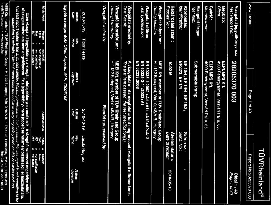
4 age 2 of 40 Report No TEST REORT Safety of household and similar electrical appliances art 2: articular requirements for pumps Report Reference No...: Tested by (name + signature)...: Tibor esze See on page 1 Witnessed by (name + signature)...: Supervised by (name + signature)...: László Nógrádi See on page 1 Approved by (name + signature)...: --- Date of issue...: CB Testing Laboratory...: Address...: Hungarian Institute for Testing and Certification of Electrical Equipment Ltd. (MEEI Ltd.) the member of TÜV Rheinland group H Budapest, Váci út 48. a-b Hungary Testing location/ procedure...: CBTL RMT SMT WM TM Type test Testing location/ address...: Applicant s name...: Hungarian Institute for Testing and Certification of Electrical Equipment Ltd. (MEEI Ltd.) the member of TÜV Rheinland group H Budapest, Váci út 48. a-b Hungary ELUMS Kft. Address...: 4900 Fehérgyarmat, Vasvári ál u. 65. Test specification: Standard...: Test procedure...: Non-standard test method..: Test Report Form No...: Test Report Form(s) Originator...: IEC :2002 (Third edition) + A1:2004 used in conjunction with IEC :2001 (Fourth Edition) modified + A1:2004+ A2:2006(added by MEEI) and/or EN : A1:2004 used in conjunction with EN : A11: A1:2004+A12:2006+A2:2006+A13:2008 (added by MEEI) and EN 62233:2008 Type test IECEN60335_2_41B + modified by MEEI VDE + modified by MEEI
5 age 3 of 40 Report No Master TRF...: Dated Copyright 2005 IEC System for Conformity Testing and Certification of Electrical Equipment (IECEE), Geneva, Switzerland. All rights reserved. This publication may be reproduced in whole or in part for non-commercial purposes as long as the IECEE is acknowledged as copyright owner and source of the material. IECEE takes no responsibility for and will not assume liability for damages resulting from the reader's interpretation of the reproduced material due to its placement and context. This report is not valid as a CB Test Report unless signed by an approved CB Testing Laboratory and appended to a CB Test Certificate issued by an NCB in accordance with IECEE 02. Test item description...: Trade Mark...: Submersible ump ELUMS Manufacturer...: ELUMS Kft Fehérgyarmat, Vasvári ál u. 65. Model/Type reference...: See page 1 Ratings...: 230V; 50Hz, 1400W (B10/4); 1600 W (B 14/4); 1000W (B 18/3); 1100 W (B 22/3); 1300 W (B1/4); IX8 Factory : ELUMS Kft Fehérgyarmat, Vasvári ál u modified by MEEI

6 age 4 of 40 Report No Copy of marking plate: Summary of testing: - The samples of type B 1/4 are identical in respect of construction to the samples of types B 10, B 14 tested under Test Report ref. No and types B 18/3 and B 22/3 tested under Test Report ref. No The only difference diameter of Submersible ump, the carry out of starter box, and rated power. Note: According to the manufacturer's declaration the B 10 and B 14 types were renamed on B 10 / 4 and B 14 / 4 types. This difference does not affect safety of the appliances based on the above and in addition test results on page This test report is based on, and valid only together with the Test Report ref. No and issued by MEEI Kft. Tests were conducted on model: B 1/4. The structures of other appliances are basically same as the unit type. During the documentation check the Hungarian User s Manual was evaluated. + modified by MEEI


7 age 5 of 40 Report No hotos: + modified by MEEI


8 age 6 of 40 Report No hotos: + modified by MEEI
9 age 7 of 40 Report No Test item particulars... : Classification of installation and use... : ortable Supply Connection... : Supply cord fitted with a plug... : -... : - ossible test case verdicts: - test case does not apply to the test object...: - test object does meet the requirement...: (ass) - test object does not meet the requirement...: F(Fail) Testing...: Date of receipt of test item...: Date (s) of performance of tests...: roduct verification per IECEE 02, Clause 6.2.5: - Steps taken by the NCB to ensure that the products - from all the factories stated in the CB Test Certificate are equal... General remarks: The test results presented in this report relate only to the object tested. This report shall not be reproduced, except in full, without the written approval of the Issuing testing laboratory. "(see Enclosure #)" refers to additional information appended to the report. "(see appended table)" refers to a table appended to the report. Throughout this report a comma (point) is used as the decimal separator. General product information / Additional remarks :-
10 age 8 of 40 Report No MARKING AND INSTRUCTIONS 7.1 Rated voltage or voltage range (V) V Nature of supply... - Rated frequency (Hz) Hz Rated power input (W): W Rated current (A)... - Manufacturer's or responsible vendor's name, ELUMS trademark or identification mark... Model or type reference... B 1/4 Symbol 5172 of IEC 60417, for Class II appliances I number, other than IX0... I X8 The enclosure of electrically-operated water valves incorporated in external hose-sets for connection of an appliance to the water mains shall be marked with symbol IEC (DB: ) if their working voltage exceeds extra-low voltage. (IEC /A1) umps having a rated power input exceeding 50 W shall be marked with: (IEC ) -the minimum total head in metres, if > 0 metres) (IEC ) -the maximum operating depth in metres, if > 1 metres (for submersible pumps) (IEC ) -the direction of rotation (three phase motor only) (IEC ) umps shall be marked with the maximum liquid temperature, which shall not be less than 35 C. (IEC ) If the temperature exceeds 35 C, they shall be marked with the maximum period of operation, unless they are intended for continuous operation. (IEC ) 7.2 Warning for stationary appliances for multiple supply 10 m
11 age 9 of 40 Report No Warning placed in vicinity of terminal cover 7.3 Range of rated values marked with the lower and upper limits separated by a hyphen Different rated values marked with the values separated by an oblique stroke 7.4 Appliances adjustable for different rated voltages, the voltage setting is clearly discernible 7.5 Appliances with more than one rated voltage or one or more rated voltage ranges, marked with rated input or rated current for each rated voltage or range, unless the power input is related to the mean value of the rated voltage range Relation between marking for upper and lower limits of rated power input or rated current and voltage is clear 7.6 Correct symbols used [symbol IEC (DB: )] equipotentiality (IEC /A1) symbol IEC (DB: )] dangerous voltage (IEC /A1) 7.7 Connection diagram fixed to appliances to be connected to more than two supply conductors and appliances for multiple supply 7.8 Except for type Z attachment, terminals for connection to the supply mains indicated as follows: - marking of terminals exclusively for the neutral conductor (N) - marking of protective earthing terminals (symbol 5019 of IEC 60417) - marking not placed on removable parts 7.9 Marking or placing of switches which may cause a hazard 7.10 Indications of switches on stationary appliances - and controls on all appliances by use of figures, letters or other visual means...
12 age 10 of 40 Report No The figure 0 indicates only OFF position, unless no confusion with the OFF position 7.11 Indication for direction of adjustment of controls 7.12 Instructions for safe use provided The instruction for use of class I portable pumps for cleaning and other maintenance of swimming pools shall include the substance of the following: (IEC ) -the pump must not be used when people are staying in the water (IEC ) -the pump must supplied through a residual current device (RCD) with a rated residual operating current < 30 ma (IEC ) The instructions for use for pumps marked with a temperature exceeding 35 C shall state the maximum period of operation and the minimum rest period, unless the pump is intended for continuous operation at this temperature. (IEC ) Sufficient details for installation supplied The installation instruction shall provide information on requirements specified for the electrical installation and shall include reference to national wiring rules If reference is made to zones, the corresponding shall be included The installation instruction shall state the substance of the following: (IEC ) - the maximum total head, in meters (for pumps having a rated power input >50W) (IEC ) - pollution of the liquid could occur due to leakage of lubricants (for submersible pumps and vertical wet pit pumps contaiming lubricants) (IEC ) - Additional information for installation of stationary pumps having a three-phase motor not incorporating a protective device as specified (IEC )
13 age 11 of 40 Report No The instructions for installation shall state that pumps for outdoor fountains, garden ponds and similar places have to be supplied through a RCD (operating current < 30 ma) (IEC ) The instructions for installation shall give full informations for installation of class I pumps for operating in swimming pools as specified (IEC ) The installation instructions for class III pumps intended to be installed in zone 0 of a swimming pool shall state that the transformer is located outside zone1 (IEC ) The installation instructions for class II pumps intended to be fixed in zone 1 of a swimming pool, or fixed close to a garden pond or similar place, shall state that the pump is to be located where flooding cannot occur (IEC ) Stationary appliances not fitted with means for disconnection from the supply mains having a contact separation in all poles that provide full disconnection under overvoltage category III, the instructions state that means for disconnection must be incorporated in the fixed wiring in accordance with the wiring rules Insulation of the fixed wiring in contact with parts exceeding 50 K during clause 11; instructions stating that the fixed wiring must be protected Instructions for built-in appliances: - dimensions of space - dimensions and position of supporting means - distances between parts and surrounding structure - dimensions of ventilation openings and arrangement - connection to supply mains and interconnection of separate components
14 age 12 of 40 Report No necessity to allow disconnection of the appliance from the supply after installation, unless the appliance incorporates a switch complying with (IEC /A1) The disconnection may be achieved by having the plug accessible or by incorporating a switch in the fixed wiring in accordance with the wiring rules. (IEC /A1) Replacement cord instructions, type X attachment with a specially prepared cord Replacement cord instructions, type Y attachment Replacement cord instructions, type Z attachment The instructions for heating appliances incorporating a non-self-resetting thermal cut-out that is reset by disconnection of the supply mains shall contain the substance of the following: (IEC /A1) CAUTION: In order to avoid a hazard due to inadvertent resetting of the thermal cut-out, this appliance must not be supplied through an external switching device, such as a timer, or connected to a circuit that is regularly switched on and off by the utility. (IEC /A1) The instructions for fixed appliances shall state how the appliance is to be fixed to its support. (IEC /A1) The instructions for appliances connected to the water mains shall state (IEC /A1) - the maximum inlet water pressure, in pascals; (IEC /A1) - the minimum inlet water pressure, in pascals, if this is necessary for the correct operation of the appliance. (IEC /A1) The instructions for appliances connected to the water mains by detachable hose-sets shall state that the new hose-sets supplied with the appliance are to be used and that old hosesets should not be reused. (IEC /A1)
15 age 13 of 40 Report No Instructions and other texts in an official language 7.14 Marking clearly legible and durable 7.15 Marking on a main part Marking clearly discernible from the outside, if necessary after removal of a cover For portable appliances, cover can be removed or opened without a tool For stationary appliances, name, trademark or identification mark and model or type reference visible after installation For fixed appliances, name, trademark or identification mark and model or type reference visible after installation according to the instructions Indications for switches and controls placed on or near the components. Marking not on parts which can be positioned or repositioned in such a way that the marking is misleading 7.16 Marking of a possible replaceable thermal link or fuse link clearly visible with regard to replacing the link 10 OWER INUT AND CURRENT 10.1 ower input at normal operating temperature, rated voltage and normal operation not deviating from rated power input by more than shown in table Current at normal operating temperature, rated voltage and normal operation not deviating from rated current by more than shown in table 2 11 HEATING 11.1 No excessive temperatures in normal use 11.2 lacing and mounting of appliance as described 11.3 Temperature rises, other than of windings, determined by thermocouples
16 age 14 of 40 Report No Temperature rises of windings determined by resistance method, unless the windings makes it difficult to make the necessary connections By resistance 11.4 Heating appliances operated under normal operation at 1.15 times rated power input..: 11.5 Motor-operated appliances operated under normal operation at most unfavourable voltage between 0.94 and 1.06 times rated voltage : 11.6 Combined appliances operated under normal operation at most unfavourable voltage between 0.94 and 1.06 times rated voltage : 11.7 umps are operated with the liquid maintained at the temperature marked on the pump. (IEC /A1) They are operated until steady conditions are established unless they are marked with a maximum period of operation. In this case, they are operated for the marked period followed by the rest period specified in the instructions, the test being carried out for three cycles of operation. (IEC /A1) Shower-boost pumps that are also supplied with cold water are operated with the cold water at 15 ºC ± 2 ºC. (IEC /A1) umps, other than shower-boost pumps, marked with a maximum period of operation are also operated with the liquid maintained at 35 ºC until steady conditions are established. (IEC /A1) If the pumb is marked with a maximum period of operation x - - the liquid temperature is 35 C instead of the marked temperature; it is also operated for this period followed by the rest period specified in the instructions for use, the liquid being maintained at the marked temperature. This test is carried out for three cycles of operation. (IEC ) 11.8 Temperature rises not exceeding values in table 3 (see appended tables)
17 age 15 of 40 Report No rotective devices do not operate However, components in protective electronic circuits are allowed to operate provided they are tested for the number of cycles of operation specified in (IEC /A1) The temperature rise limit does not apply to switches or controls tested in accordance with the conditions occurring in the appliance. (IEC /A1) Sealing compound does not flow out For pumps marked with a temperature exceeding 35 C, the temperature rise of the external enclosure is not measured. (IEC ) 13 LEAKAGE CURRENT AND ELECTRIC STRENGTH AT OERATING TEMERATURE 13.1 Leakage current not excessive and electric strength adequate Heating appliances operated at 1.15 times - rated power input... Motor-operated appliances and combined 243,8 V appliances supplied at 1.06 times rated voltage... rotective impedance and radio interference filters disconnected before carrying out the tests 13.2 Leakage current measured by means of the circuit described in figure 4 of IEC Leakage current measurements (see appended table) 13.3 The appliance is disconnected from the supply and the insulation is immediately subjected to a voltage having a frequency of 50 Hz or 60 Hz for 1 min, in accordance with IEC (IEC /A1) The high-voltage source used for the test is to be capable of supplying a short circuit current Is between the output terminals after the output voltage has been adjusted to the appropriate test voltage. (IEC /A1)
18 age 16 of 40 Report No The overload release of the circuit is not to be operated by any current below the tripping current Ir. The values of Is and Ir are given in Table 5 for various high-voltage sources. (IEC /A1) 15 MOISTURE RESISTANCE 15.1 Enclosure provides the degree of moisture protection according to classification of the appliance Compliance checked as specified in , taking into account , followed by the electric strength test of 16.3 No trace of water on insulation which can result in a reduction of clearances and creepage distances below values specified in clause Appliances, other than IX0, subjected to tests I X8 as specified in IEC Water valves containing live parts and that are incorporated in external hoses for connection of an appliance to the water mains are subjected to the test specified for IX7 appliances. (IEC /A1) Shower-boost pumps are subjected to the appropriate test of IEC both at rest and in operation while supplied at rated voltage. (IEC /A1) Hand-held appliance turned continuously through the most unfavourable positions during the test Built-in appliances installed according to the instructions Appliances placed or used on the floor or table placed on a horizontal unperforated support Appliances normally fixed to a wall and appliances with pins for insertion into socketoutlets are mounted on a wooden board For IX3 appliances, the base of wall mounted appliances is placed at the same level as the pivot axis of the oscillating tube
19 age 17 of 40 Report No For IX4 appliances, the horizontal centre line of the appliance is aligned with the pivot axis of the oscillating tube However, for appliances normally used on the floor or table, the movement is limited to two times 90 for a period of 5 min, the support being placed at the level of the pivot axis of the oscillating tube Wall-mounted appliances, take into account the distance to the floor stated in the instructions Appliances normally fixed to a ceiling are mounted underneath a horizontal unperforated support that is constructed to prevent water spraying onto its top surface. The pivot axis of the oscillating tube is located at the same level as the underside of the support and aligned centrally with the appliance. The spray is directed upwards. (IEC /A1) For IX4 appliances, the movement of the tube is limited to two times 90º from the vertical for a period of 5 min. (IEC /A1) Appliances with type X attachment fitted with a flexible cord as described Detachable parts tested as specified I X4 pumps are tested as specified (IEC ) I X7-pumps (submersible pumps) are immersed for 24 h in water as specified (IEC ) 1,5 times the pressure occurring at the maximum operation depth, when this depth does not exceed 10m (IEC ) 1,3 times the pressure occurring at the maximum operating depth, or 15 m, if this is higher. (IEC /A1) 15.2 Spillage of liquid does not affect the electrical insulation Appliances with type X attachment fitted with a flexible cord as described
20 age 18 of 40 Report No Appliances incorporating an appliance inlet tested with or without an connector, whichever is most unfavourable Detachable parts removed Overfilling test with additional amount of - water, over a period of 1 min (l)... The appliance withstands the electric strength test of 16.3 No trace of water on insulation that can result in a reduction of clearances and creepage distances below values specified in clause Appliances proof against humid conditions Humidity test for 48 h in a humidity cabinet (not for submersible pumps) (IEC ) The appliance withstands the tests of clause 16 controlling box 16 LEAKAGE CURRENT AND ELECTRIC STRENGTH 16.1 Leakage current not excessive and electric strength adequate rotective impedance disconnected from live parts before carrying out the tests 16.3 Electric strength tests according to table 7 (see appended table) No breakdown during the tests 17 OVERLOAD ROTECTION OF TRANSFORMERS AND ASSOCIATED CIRCUITS No excessive temperatures in transformer or associated circuits in event of short-circuits likely to occur in normal use (see appended table) Appliance supplied with 1.06 or 0.94 times rated voltage and the most unfavourable shortcircuit or overload likely to occur in normal use applied... - Temperature rise of insulation of the conductors of safety extra-low voltage circuits not exceeding the relevant value specified in table 3 by more than 15 K
21 age 19 of 40 Report No Temperature of the winding not exceeding the value specified in table 8, however limits do not apply to fail-safe transformers complying with sub-clause 15.5 of IEC ABNORMAL OERATION 19.1 The risk of fire or mechanical damage under abnormal or careless operation obviated Electronic circuits so designed and applied that a fault will not render the appliance unsafe umps are also subjected to the tests of and (IEC ) 19.2 Test of appliance with heating elements with restricted heat dissipation; test voltage (V): power input of 0.85 times rated power input Test of 19.2 repeated; test voltage (V): power input of 1.24 times rated power input Test conditions as in cl. 11, any control limiting the temperature during tests of cl. 11 short-circuited 19.5 Test of 19.4 repeated on Class 0I and I appliances with tubular sheathed or embedded heating elements. No short-circuiting, but one end of the element connected to the elements sheath The test repeated with reversed polarity and the other end of the heating element connected to the sheath The test is not carried out on appliances intended to be permanently connected to fixed wiring and on appliances where an all-pole disconnection occurs during the test of Appliances with TC heating elements tested at rated voltage, establishing steady conditions The working voltage of the TC heating element is increased by 5% and the appliance is operated until steady conditions are reestablished. The voltage is then increased in similar steps until 1.5 times working voltage or until the TC heating element ruptures
22 age 20 of 40 Report No Stalling test by locking the rotor if the locked rotor torque is smaller than the full load torque or locking moving parts of other appliances Locked rotor, motor capacitors open-circuited or short-circuited, if required Locked rotor, capacitors open-circuited one at a time Test repeated with capacitors short-circuited one at a time, if required Appliances with timer or programmer supplied with rated voltage for each of the tests, for a period equal to the maximum period allowed Other appliances supplied with rated voltage for a period as specified Winding temperatures not exceeding values specified in table Three-phase motors operated at rated voltage with one phase disconnected (see appended table) Series motor operated at 1.3 times rated - voltage for 1 min... During the test, parts not being ejected from the appliance Electronic circuits, compliance checked by evaluation of the fault conditions specified in for all circuits or parts of circuits, unless they comply with the conditions specified in Appliances incorporating a protective electronic circuit are subjected to the tests of and (IEC /A1) Appliances having a switch with an off position obtained by electronic disconnection, or a switch that can place the appliance in a standby mode, are subjected to the tests of (IEC /A1) During and after each test the following is checked: - the temperature rise of the windings do not exceed the values specified in table 8
23 age 21 of 40 Report No the appliance complies with the conditions specified in any current flowing through protective impedance not exceeding the limits specified in If a conductor of a printed board becomes open-circuited, the appliance is considered to have withstood the particular test, provided all three of the following conditions are met: - the material of the printed circuit board withstands the burning test of annex E - any loosened conductor does not reduce the clearances or creepage distances between live parts and accessible metal parts below the values specified in cl the appliance withstands the tests of with open-circuited conductor bridged Before applying the fault conditions a) to f) in , it is checked if circuits or parts of circuit meet both of the following conditions: - the electronic circuit is a low-power circuit, that is, the maximum power at low-power points does not exceed 15 W according to the tests specified - the protection against electric shock, fire hazard, mechanical hazard or dangerous malfunction in other parts of the appliance does not rely on the correct functioning of the electronic circuit Fault conditions applied one at a time, the appliance operated under conditions specified in cl. 11, but supplied at rated voltage, the duration of the tests as specified: a) short circuit of functional insulation if clearances or creepage distances are less than the values specified in 29 b) open circuit at the terminals of any component c) short circuit of capacitors, unless they comply with IEC
24 age 22 of 40 Report No d) short circuit of any two terminals of an electronic component, other than integrated circuits. This fault condition is not applied between the two circuits of an optocoupler e) failure of triacs in the diode mode f) failure of an integrated circuit. In each case, the test is ended if a non-selfresetting interruption of the supply occurs within the appliance. (IEC /A1) If the appliance incorporates a protective electronic circuit which operates to ensure compliance with clause 19, the relevant test is repeated with a single fault simulated, as indicated in a) to f) of Appliances having a switch with an off position obtained by electronic disconnection, or a switch that can be placed in the stand-by mode, are subjected to the tests of to The tests are carried out with the appliance supplied at rated voltage, the switch being set in the off position or in the stand-by mode. (IEC /A1) Appliances incorporating a protective electronic circuit are subjected to the tests of to The tests are carried out after the protective electronic circuit has operated during the relevant tests of Clause 19 except 19.2, 19.6 and However, appliances that are operated for 30 s or 5 min during the test of 19.7 are not subjected to the tests for electromagnetic phenomena. (IEC /A1) The tests are carried out with surge arresters disconnected, unless they incorporate spark gaps (IEC /A1) The appliance is subjected to electrostatic discharges in accordance with IEC , test level 4 being applicable. Ten discharges having a positive polarity and ten discharges having a negative polarity are applied at each preselected point (IEC /A1) The appliance is subjected to radiated fields in accordance with IEC , test level 3 being applicable. (IEC /A1)
25 age 23 of 40 Report No The appliance is subjected to fast transient bursts in accordance with IEC Test level 3 s applicable for signal and control lines. Test level 4 is applicable for the power supply lines. The bursts are applied for 2 min with a positive polarity and for 2 min with a negative polarity (IEC /A1) The power supply terminals of the appliance are subjected to voltage surges in accordance with IEC , five positive impulses and five negative impulses being applied at the selected points. Test level 3 is applicable for the line-to-line coupling mode, a generator having a source impedance of 2 Ω being used. Test level 4 is applicable for the line-toearth coupling mode, a generator having a source impedance of 12 Ω being used. (IEC /A1) Earthed heating elements in class I appliances are disconnected during this test (IEC /A1) For appliances having surge arresters incorporating spark gaps, the test is repeated at a level that is 95 % of the flashover voltage (IEC /A1) The appliance is subjected to injected currents in accordance with IEC , test level 3 being applicable. During the test, all frequencies between 0,15 MHz to 80 MHz are covered. (IEC /A1) The appliance is subjected to voltage dips and interruptions in accordance with IEC The durations specified in Table 1 of IEC are applied to each test level, the dips and interruptions being applied at zero crossing of the supply voltage (IEC /A1) The appliance is subjected to mains signals in accordance with IEC , test level class 2 being applicable (IEC /A1)
26 age 24 of 40 Report No If the safety of the appliance for any of the fault conditions specified in depends on the operation of a miniature fuse-link complying with IEC 60127, the test is repeated, measuring the current flowing through the fuse-link; measured current (A); rated current of the fuselink (A) During the tests the appliance does not emit flames, molten metal, poisonous or ignitable gas in hazardous amounts Temperature rises not exceeding the values shown in table 9 Enclosures not deformed to such an extent that compliance with cl. 8 is impaired If the appliance can still be operated it complies with 20.2 The appliance shall not undergo a dangerous malfunction, and there shall be no failure of protective electronic circuits if the appliance is still operable. (IEC /A1) Appliances tested with an electronic switch in the off position, or in the stand-by mode, shall not become operational (IEC /A1) Insulation, other than of class III appliance, withstand the electric strength test of 16.3, the test voltage specified in table 4: - basic insulation V - supplementary insulation V - reinforced insulation V The pump is supplied at rated voltage and operated at approximately half at the maximum total head for 5 min, (IEC ) After which the inlet is removed from the liquid and the operation continued for 7h (IEC ) umps are operated again for 5 min at approximately half the maximum total head (IEC )
27 age 25 of 40 Report No If the pump becomes inoperable during the test., it is disconnected from the supply and filled with water (IEC ) umps marked with a maximum period of operation are supplied at rated voltage and operated under normal operation until steady conditions are established. (IEC ) 30 RESISTANCE TO HEAT AND FIRE 30.1 External parts of non-metallic material, parts supporting live parts, and thermoplastic material providing supplementary or reinforced insulation, sufficiently resistant to heat Ball-pressure test according to IEC External parts: at 40 C plus the maximum temperature rise determined during the test of clause 11, or at 75 C, whichever is the higher; temperature ( C) arts supporting live parts: at 40 C plus the maximum temperature rise determined during the test of clause 11, or at 125 C, whichever is the higher; temperature ( C) arts of thermoplastic material providing supplementary or reinforced insulation, 25 C plus the maximum temperature rise determined during clause 19, if higher; temperature ( C) Relevant parts of non-metallic material adequately resistant to ignition and spread of fire Glow-wire test of IEC at 550 C, unless the material is classified at least HB40 according to IEC arts for which the glow-wire test cannot be carried out meet the requirements in ISO9772 for category HBF material Appliances operated while unattended, tested as specified in and
28 age 26 of 40 Report No Test not applicable to conditions as specified arts of insulating material supporting connections carrying a current exceeding 0.2A during normal operation, and parts of insulating material within a distance of 3mm, having a glow-wire flammability index of at least 850 C according to IEC arts of insulating material supporting currentcarrying connections, and parts of insulating material within a distance of 3mm, subjected to glow-wire test of IEC Test not carried out on material having a glowwire ignition temperature according to IEC as specified Glow-wire test of IEC , the temperature being: C, for connections carrying a current exceeding 0,2A during normal operation C, for other connections arts that during the test produce a flame persisting longer than 2 s, tested as specified If a flame persists longer than 2 s during the test, parts above the connection, as specified, subjected to the needle-flame test of annex E, unless the material is classified as V-0 or V-1 according to IEC Base material of printed circuit boards subjected to needle-flame test of annex E Test not applicable to conditions as specified D ANNEX D (NORMATIVE) THERMAL MOTOR ROTECTORS Applicable to appliances having motors that incorporate thermal motor protectors
29 age 27 of 40 Report No AENDIX 1: To complete the assessment according to EN / EN the following requirements are considered as well : GROU DIFFERENCES to IEC , 4 th ed (CB Bulletin 107B) 7.1 Rated voltage or voltage range shall cover V for single-phase appliances V for multi-phase appliances 230 V Appendix 1: Tables with test results Tables: 10.1 TABLE: ower input deviation Input deviation of/at: rated (W) measured (W) d (W) Required d 230 V % (195W) Remark 10.2 TABLE: Current deviation Current deviation of/at: I rated (A) I measured (A) di Required di Remark -
30 Oldal/ age 28 / 40 Test report No.: 282xxxxx yyy 11.8 TABLE: Heating test, thermocouples Test voltage (V)... : 243,8 Ambient ( C)... : 22,6 Thermocouple locations dt (K) Max. dt (K) Capacitor 15,5 20 Supply cord 16,4 50 Switch 30,7 75 Internal wire 15,8 50 Enclosure 8, TABLE: Heating test, resistance method Test voltage (V)... : 243,8 Ambient, t 1 ( C)... : 35 Ambient, t 2 ( C)... : 35 Temperature rise of winding R 1 ( ) R 2 ( ) dt (K) Max. dt (K) Insulation class Main winding 6,17 6,99 35, Auxiliary winding 8,56 9,70 35, TABLE: Leakage current Heating appliances: 1.15 x rated input... : Motor-operated and combined appliances: 1.06 x rated voltage... : 243,8 Leakage current between I (ma) Max. allowed I (ma) Basic insulation 0,32 0,75 Reinforced insulation 0,01 0, TABLE: Electric strength Test voltage applied between: Voltage (V) Breakdown (Yes/No) Basic insulation 1000 No Reinforced insulation 3000 No
31 age 29 of 40 Report No TABLE: Electric strength * Test voltage applied between: Voltage (V) Breakdown (Yes/No) Basic insulation 1250 No Reinforced insulation 3000 No *carried out after TABLE: Abnormal operation, locked rotor/moving parts* Test voltage (V)... : Ambient, t 1 ( C)... : Ambient, t 2 ( C)... : Temperature of winding R 1 ( ) R 2 ( ) dt (K) T ( C) Max. T ( C)
32 age 30 of 40 Report No TABLE: Components Object / part No. Manufacturer/ trademark Motor B 18/3 Jiadi pump Industry Co, Ltd. Type / model Technical data Standard Mark(s) of conformity 75QJ2 230V/1000W EN EN Tested in appliance Motor B22/3 Jiadi pump Industry Co, Ltd. 75QJ2 230V/1100W EN EN Tested in appliance Motor B 1/4 Motor B10/4 Motor B14/4 lug B 10/4, B14/4 B 18/3 B 22/3 B 1/4 Jiadi pump Industri Co.,Ltd. 4 SKm V/1300W EN EN Zheijang LEO Ltd. 4XR series 230V/1400W EN EN Zheijang LEO Ltd. 4XR series 230V/1600W EN EN Zheijang JT 3F 16A/250V DIN VDE VDE Tested in appliance Tested in appliance Tested in appliance alternativ Zheijang SY-08 16A/250V DIN VDE VDE alternativ Ningbo YD3-F 10/16 DIN VDE Cord and flexible cable B 10/4, B14/4 B18/3,B22/3 B1/4 Capacitor B 18/3; B22/3 Capacitor B14/4 B10/4 B 1/4 Overload protection in motor B10/4,B14/4 B18/3,B22/3 B 1/4 ump cord B10/4,B14/4 B 1/4 various H07RN-F 3G1 245IEC66 VDE AEG Components a.s. Zheijang Taizhou Shuangfeng Electronic Co., Ltd. Hangzou Yongqiang Cable Co., Ltd. MK F 330V~ 50/60Hz CBB F 450V~ 50/60Hz EN EN EN EN VDE VDE Tested in appliance H07RN- F 4G1,0mm 2 245IEC66 VDE
33 age 31 of 40 Report No ump cord B 18/3;B22/3 Overload protection in control box B10/4,B14/4 Ningbo Huashun Electronics Co., Ltd. H07RN-F 4G0,75 245IEC66 VDE RONG FENG RFMB 8 A 250 V EN EN készülékben vizsgálva Overload protection in control box B18/3.B 22/3 B 1/4 Switch B10/4,B14/4 B 1/4 Switch B18/3;B 22/3 Terminal block B10/4,B14/4 B18/3,B22/3 B 1/4 Kuoyoh W.L.. Enterprise Co. 88, 98 AC V, DC 32 V, 3-16 A GAOTIAN KR-06 16A 250V~ T85 1E4 Ningbo Soken Electrical Co., Ltd. Ningbo Soken Electrical Co., Ltd. EN EN VDE TÜV RK-1, RK 2 16A 250V~ T100 EN VDE K 10 A 400 V EN VDE 1) An asterisk indicates a mark which assures the agreed level of surveillance
34 age 32 of 40 Report No TABLE: Ball pressure art Test temperature ( C) Impression diameter (mm) Allowed impression diameter (mm) controlling box cover 75 1,5 2 IEC / EN /A2 7 MARKING AND INSTRUCTIONS 7.5 The power input is related to the arithmetic mean value of the rated voltage range 7.6 Correct symbols used 7.12 Instructions for safe use provided The instructions state that: - the appliance is not to be used by children or persons with reduced physical, sensory or mental capabilities, or lack of experience and knowledge, unless they have been given supervision or instruction 10 OWER INUT AND CURRENT 10.1 The permissible deviations apply for both limits of the range for appliances marked with a rated voltage range having limits differing by more than 10 % of the arithmetic mean value of the range. Test for an appliance with one or more rated voltage ranges Note 1 and 2 do not apply 10.2 The permissible deviations apply for both limits of the range for appliances marked with a rated voltage range having limits differing by more than 10 % of the arithmetic mean value of the range. Test for an appliance with one or more rated voltage ranges
35 age 33 of 40 Report No HEATING IEC / EN /A2 Table 3 First entry: Replace the terms class A, class B, class F and class H by the terms class 105, class 120, class 130, class 155 and class 180 Table 3: Fifth entry: Rubber, polychloroprene or polyvinyl chloride insulation of internal and external wiring, including supply cords: without temperature rating or with a temperature rating not exceeding 75 C with temperature rating (T) where T exceeds 75 C Footnote: The temperature rise limit of windings in transformers and inductors mounted on printed circuit boards is equal to the thermal class of the winding insulation reduced by 25 K provided the largest dimension of the winding does not exceed 5 mm in cross section or length. j: IEC Types 53, 57 and 87 supply cords have a T rating of 60 C; IEC Types 52 and 53 supply cords have a T rating of 70 C; IEC Types 56 and 57 supply cords have a T rating of 90 C. 16 LEAKAGE CURRENT AND ELECTRIC STRENGTH 16.3 Electric strength tests according to table 7 (accordance with IEC ) Note 2: The characteristics of the high-voltage source used for the test are described in Table 5. Delete the penultimate paragraph of the test specification. 19 ABNORMAL OERATION 19.1 Appliances incorporating contactors or relays subjected to the test of In the second paragraph, replace IEC by IEC (see appended table)
36 age 34 of 40 Report No IEC / EN /A Replace the second and third paragraphs by the following: Appliances incorporating an electronic circuit are subjected to the tests of and Appliances incorporating an electronic circuit that relies upon a programmable component to function correctly, subjected to the test of In the existing third paragraph, replace switch by device in two places. In the sixth paragraph replace all three by both and delete the last dashed item g) failure of an electronic power switching device in a partial turn-on mode with loss of gate (base) control. During this test, winding temperatures shall not exceed the values given in In the first paragraph, replace switch by device in three places. In the last paragraph, replace "arresters" by "protective devices The appliance is subjected to the Class 3 voltage dips and interruptions in accordance with IEC The appliance is supplied at rated voltage and operated under normal operation. After 60s the power supply is reduced to a level such that the appliance ceases to respond or a programmable component cease to operate. The appliance continues to operate normally or requires a manual operation to restart After the tests, and when the appliance has cooled to approximately room temperature, compliance with Clause 8 shall not be impaired and the appliance shall comply with 20.2 if it can still be operated. After operation or interruption of a control, clearances and creepage distances across the functional insulation withstanding the electric strength test of the test voltage being twice the working voltage Appliances tested with an electronic switch in the off position, or in the stand-by mode: - do not become operational, or - if they become operational, do not result in a dangerous malfunction during or after the tests of Note: Unintended operation that may impair safety can result from careless use of appliances, such as: - storage of small appliances while connected to the supply;
37 age 35 of 40 Report No IEC / EN /A2 placing flammable material on working surfaces of heating appliances; or placing objects in areas near motorized appliances that are not expected to start Appliances operated under the conditions of Clause 11. Contactors or relays contacts operating under the conditions of clause 11 short-circuited
38 age 36 of 40 Report No RESISTANCE TO HEAT AND FIRE IEC / EN /A arts of non-metallic material adequately resistant to ignition and spread of fire. This requirement does not apply to decorative trims, knobs and other parts unlikely to be ignited or to propagate flames that originate inside the appliance. Compliance checked by the test of In addition: - attended appliances, applies - unattended appliances, applies Appliances for remote operation, applies. Base material of printed circuit board, applies. The tests are carried out on parts of non-metallic material that have been removed from the appliance. When the glow-wire test is carried out, the parts are placed in the same orientation, as they would be in normal use Glow-wire test of IEC at 550 C, unless the material is classified at least HB40 according to IEC arts for which the glow-wire test cannot be carried out meet the requirements in ISO9772 for category HBF material Appliances operated while attended, parts of nonmetallic material supporting current-carrying connections, and parts of non-metallic material within a distance of 3mm of such connections, are subjected to the glow-wire test of IEC The glow-wire test is not carried out on parts of material classified as having a glow-wire flammability index according to IEC of at least: -750 C, for connections carrying a current exceeding 0,5 A during normal operation -650 C, for other connections Test as specified for an interposed shielding material When the glow-wire test of IEC is carried out, the temperatures are: -750 C, for connections carrying a current exceeding 0,5 A during normal operation -650 C, for other connections Test not applicable to conditions as specified Appliances operated while unattended, tested as specified in and Tests not applicable to conditions as specified
39 age 37 of 40 Report No IEC / EN /A arts of non-metallic material supporting connections that carry a current exceeding ,2 A during normal operation, and parts of nonmetallic material within a distance of 3 mm of such connections, are subjected to the glow-wire test of IEC with a test severity of 850 C. However, the glow-wire test is not carried out on parts of material classified as having a glow-wire flammability index of at least 850 C according to IEC If the glow-wire flammability index is not available for a sample with a thickness within ± 0,1 mm of the relevant part, then the test sample shall have a thickness equal to the nearest preferred value specified in IEC that is no thicker than the relevant part. NOTE 1 The preferred values in IEC are 0,75 mm ± 0,1 mm, 1,5 mm ± 0,1 mm and 3,0 mm ± 0,2 mm. NOTE 2 Contacts in components such as switch contacts are considered to be connections. NOTE 3 The tip of the glow-wire is applied to the part in the vicinity of the connection. The glow-wire test is also not carried out on small parts that comply with the needle-flame test of Annex E or on small parts of material classified as V-0 or V-1 according to IEC provided that the test sample used for the classification was no thicker than the relevant part of the appliance. NOTE 4 Small parts are as defined in IEC Where a non-metallic material is within 3 mm of a current carrying connection, but is shielded from the connection by a different material, the glow-wire test of IEC is carried out at the relevant temperature with the tip of the glow-wire applied to the interposed shielding material with the shielded material in place and not directly to the shielded material. arts of non-metallic material supporting currentcarrying connections, and parts of non-metallic material within a distance of 3 mm of such connections, are subjected to the glow-wire test of IEC However, the glow-wire test is not carried out on parts of material classified as having a glow-wire ignition temperature according to IEC of at least 775 C, for connections that carry a current exceeding 0,2 A during normal operation, 675 C, for other connections.
40 age 38 of 40 Report No IEC / EN /A2 If the glow-wire ignition temperature is not available for a sample with a thickness within ± 0,1 mm of the relevant part, then the test sample shall have a thickness equal to the nearest preferred value specified in IEC that is no thicker than the relevant part. NOTE 1 The preferred values in IEC are 0,75 mm ± 0,1 mm, 1,5 mm ± 0,1 mm and 3,0 mm ± 0,2 mm. Where an non-metallic material is within 3 mm of a current carrying connection, but is shielded from the connection by a different material, the glow-wire test of IEC is carried out at the relevant temperature with the tip of the glow-wire applied to the interposed shielding material with the shielded material in place and not directly to the shielded material. When the glow-wire test of IEC is carried out, the temperatures are 750 C, for connections that carry a current exceeding 0,2 A during normal operation, 650 C, for other connections. NOTE 2 Contacts in components such as switch contacts are considered to be connections. NOTE 3 The tip of the glow-wire is applied to the part in the vicinity of the connection. If parts that withstand the glow-wire test of IEC , but during the test produce a flame that persists for longer than 2 s, then these parts and adjacent parts are further tested as follows. arts above the connection within the envelope of a vertical cylinder having a diameter of 20 mm and a height of 50 mm are subjected to the needleflame test of Annex E. However, parts shielded by a flame barrier that meets the needle-flame test of Annex E are not tested. The needle-flame test is not carried out on parts of material classified as V-0 or V-1 according to IEC provided that the test sample used for the classification was no thicker than the relevant part of the appliance.
41 age 39 of 40 Report No IEC / EN /A Base material of printed circuit boards subjected to needle-flame test of annex E No CB D Test is not applicable to conditions as specified ANNEX D (NORMATIVE) THERMAL MOTOR ROTECTORS Delete the note EN :2002/A13:2008 Clause Requirement Test Result Remark Verdict 24 Components Remote operation is via telecommunication network. (Telecommunication interface circuity: EN and EN :2006, subclause 6.3) EMF EN 62233:2008 The tested product also complies to the requirements of EN 62233:2008 Limit 100% Measured max. : 64 %
42 age 40 of 40 Report No List of test equipment used: Mér eszköz Measuring equipment Gyártó Manufactu rer Típus Type Leltári sz. / széria sz. Inventory / Serial No. Köv. kalibráció Next calibration Dielectric strength tester Kikusui TOS Leakage current measurer HIOKI Data acquisition system DATCON DT Digital wattmeter Waldsee Electronic LVM Ohm meter Ganz DKE / DMM Norma M Megjegyzés / Remark:


43
44 age 2 of 37 Report No TEST REORT Safety of household and similar electrical appliances art 2: articular requirements for pumps Report Reference No...: Tested by (name + signature)...: Tibor esze See on page 1 Witnessed by (name + signature)...: Supervised by (name + signature)...: Zoltán Zsákai See on page 1 Approved by (name + signature)...: --- Date of issue...: CB Testing Laboratory...: Address...: Hungarian Institute for Testing and Certification of Electrical Equipment Ltd. (MEEI Ltd.) the member of TÜV Rheinland group H Budapest, Váci út 48. a-b Hungary Testing location/ procedure...: CBTL RMT SMT WM TM Type test Testing location/ address...: Applicant s name...: Hungarian Institute for Testing and Certification of Electrical Equipment Ltd. (MEEI Ltd.) the member of TÜV Rheinland group H Budapest, Váci út 48. a-b Hungary ELUMS Kft. Address...: 4900 Fehérgyarmat, Vasvári ál u. 65. Test specification: Standard...: Test procedure...: Non-standard test method..: Test Report Form No...: Test Report Form(s) Originator...: IEC :2002 (Third edition) + A1:2004 used in conjunction with IEC :2001 (Fourth Edition) modified + A1:2004+ A2:2006(added by MEEI) and/or EN : A1:2004 used in conjunction with EN : A11: A1:2004+A12:2006+A2:2006+A13:2008 (added by MEEI) and EN 50366: A1:2006 Type test IECEN60335_2_41B + modified by MEEI VDE Master TRF...: Dated modified by MEEI
45 age 3 of 37 Report No Copyright 2005 IEC System for Conformity Testing and Certification of Electrical Equipment (IECEE), Geneva, Switzerland. All rights reserved. This publication may be reproduced in whole or in part for non-commercial purposes as long as the IECEE is acknowledged as copyright owner and source of the material. IECEE takes no responsibility for and will not assume liability for damages resulting from the reader's interpretation of the reproduced material due to its placement and context. This report is not valid as a CB Test Report unless signed by an approved CB Testing Laboratory and appended to a CB Test Certificate issued by an NCB in accordance with IECEE 02. Test item description...: Trade Mark...: Submersible ump ELUMS Manufacturer...: ELUMS Kft Fehérgyarmat, Vasvári ál u. 65. Model/Type reference...: B 8; B 10; B 14; B18/3; B 22/3 Ratings...: 230V; 50Hz, 1400W (B 8; B10); 1600 W (B 14); 1000W (B 18/3); 1100 W (B 22/3); IX8 Factory : ELUMS Kft Fehérgyarmat, Vasvári ál u modified by MEEI


46 age 4 of 37 Report No Copy of marking plate: Summary of testing: - The samples of type B 18/3 and B 22/3 are identical in respect of construction to the samples of types B 8, B 10, B 14 tested under Test Report ref. No The only difference less diameter of Submersible ump, the carry out of starter box, and rated power. This difference does not affect safety of the appliances based on the above and in addition test results on page This test report is based on, and valid only together with the Test Report ref. No issued by MEEI Kft. Tests were conducted on model: B 22/3. The structures of other appliances are basically same as the unit type. During the documentation check the Hungarien User s Manual was evaluated. hotos: + modified by MEEI


 - test object does not meet the requirement...: F(Fail) Testing.")
47 age 5 of 37 Report No Test item particulars... : Classification of installation and use... : ortable Supply Connection... : Supply cord fitted with a plug... : -... : - ossible test case verdicts: - test case does not apply to the test object...: - test object does meet the requirement...: (ass) - test object does not meet the requirement...: F(Fail) Testing...: Date of receipt of test item...:
48 age 6 of 37 Report No Date (s) of performance of tests...: roduct verification per IECEE 02, Clause 6.2.5: - Steps taken by the NCB to ensure that the products - from all the factories stated in the CB Test Certificate are equal... General remarks: The test results presented in this report relate only to the object tested. This report shall not be reproduced, except in full, without the written approval of the Issuing testing laboratory. "(see Enclosure #)" refers to additional information appended to the report. "(see appended table)" refers to a table appended to the report. Throughout this report a comma (point) is used as the decimal separator. General product information / Additional remarks : The basic part of this report covers the assessment of the general IEC requirements. The AENDIX 1 includes the assessment of all group differences and national deviations to complete the assessment for CENELEC countries (according the last valid edition of the CB-Bulletin and the relevant EN standards). The AENDIX 2 includes all tables with the test results and photos of the appliances. The AENDIX 3 (if any) includes the assessment of further national differences as requested by the applicant (according to the last valid edition of the CB-Bulletin). 7 MARKING AND INSTRUCTIONS 7.1 Rated voltage or voltage range (V) V Nature of supply... - Rated frequency (Hz) Hz Rated power input (W): ; 1100 W Rated current (A)... - Manufacturer's or responsible vendor's name, ELUMS trademark or identification mark... Model or type reference... B 18/3; B 22/3
49 age 7 of 37 Report No Symbol 5172 of IEC 60417, for Class II appliances I number, other than IX0... I X8 The enclosure of electrically-operated water valves incorporated in external hose-sets for connection of an appliance to the water mains shall be marked with symbol IEC (DB: ) if their working voltage exceeds extra-low voltage. (IEC /A1) umps having a rated power input exceeding 50 W shall be marked with: (IEC ) -the minimum total head in metres, if > 0 metres) (IEC ) -the maximum operating depth in metres, if > 1 metres (for submersible pumps) (IEC ) -the direction of rotation (three phase motor only) (IEC ) umps shall be marked with the maximum liquid temperature, which shall not be less than 35 C. (IEC ) If the temperature exceeds 35 C, they shall be marked with the maximum period of operation, unless they are intended for continuous operation. (IEC ) 7.2 Warning for stationary appliances for multiple supply Warning placed in vicinity of terminal cover 7.3 Range of rated values marked with the lower and upper limits separated by a hyphen Different rated values marked with the values separated by an oblique stroke 7.4 Appliances adjustable for different rated voltages, the voltage setting is clearly discernible 7.5 Appliances with more than one rated voltage or one or more rated voltage ranges, marked with rated input or rated current for each rated voltage or range, unless 10 m
50 age 8 of 37 Report No the power input is related to the mean value of the rated voltage range Relation between marking for upper and lower limits of rated power input or rated current and voltage is clear 7.6 Correct symbols used [symbol IEC (DB: )] equipotentiality (IEC /A1) symbol IEC (DB: )] dangerous voltage (IEC /A1) 7.7 Connection diagram fixed to appliances to be connected to more than two supply conductors and appliances for multiple supply 7.8 Except for type Z attachment, terminals for connection to the supply mains indicated as follows: - marking of terminals exclusively for the neutral conductor (N) - marking of protective earthing terminals (symbol 5019 of IEC 60417) - marking not placed on removable parts 7.9 Marking or placing of switches which may cause a hazard 7.10 Indications of switches on stationary appliances - and controls on all appliances by use of figures, letters or other visual means... The figure 0 indicates only OFF position, unless no confusion with the OFF position 7.11 Indication for direction of adjustment of controls 7.12 Instructions for safe use provided The instruction for use of class I portable pumps for cleaning and other maintenance of swimming pools shall include the substance of the following: (IEC ) -the pump must not be used when people are staying in the water (IEC ) -the pump must supplied through a residual current device (RCD) with a rated residual operating current < 30 ma (IEC )
51 age 9 of 37 Report No The instructions for use for pumps marked with a temperature exceeding 35 C shall state the maximum period of operation and the minimum rest period, unless the pump is intended for continuous operation at this temperature. (IEC ) Sufficient details for installation supplied The installation instruction shall provide information on requirements specified for the electrical installation and shall include reference to national wiring rules If reference is made to zones, the corresponding shall be included The installation instruction shall state the substance of the following: (IEC ) - the maximum total head, in meters (for pumps having a rated power input >50W) (IEC ) - pollution of the liquid could occur due to leakage of lubricants (for submersible pumps and vertical wet pit pumps contaiming lubricants) (IEC ) - Additional information for installation of stationary pumps having a three-phase motor not incorporating a protective device as specified (IEC ) The instructions for installation shall state that pumps for outdoor fountains, garden ponds and similar places have to be supplied through a RCD (operating current < 30 ma) (IEC ) The instructions for installation shall give full informations for installation of class I pumps for operating in swimming pools as specified (IEC ) The installation instructions for class III pumps intended to be installed in zone 0 of a swimming pool shall state that the transformer is located outside zone1 (IEC )
52 age 10 of 37 Report No The installation instructions for class II pumps intended to be fixed in zone 1 of a swimming pool, or fixed close to a garden pond or similar place, shall state that the pump is to be located where flooding cannot occur (IEC ) Stationary appliances not fitted with means for disconnection from the supply mains having a contact separation in all poles that provide full disconnection under overvoltage category III, the instructions state that means for disconnection must be incorporated in the fixed wiring in accordance with the wiring rules Insulation of the fixed wiring in contact with parts exceeding 50 K during clause 11; instructions stating that the fixed wiring must be protected Instructions for built-in appliances: - dimensions of space - dimensions and position of supporting means - distances between parts and surrounding structure - dimensions of ventilation openings and arrangement - connection to supply mains and interconnection of separate components - necessity to allow disconnection of the appliance from the supply after installation, unless the appliance incorporates a switch complying with (IEC /A1) The disconnection may be achieved by having the plug accessible or by incorporating a switch in the fixed wiring in accordance with the wiring rules. (IEC /A1) Replacement cord instructions, type X attachment with a specially prepared cord Replacement cord instructions, type Y attachment Replacement cord instructions, type Z attachment
53 age 11 of 37 Report No The instructions for heating appliances incorporating a non-self-resetting thermal cut-out that is reset by disconnection of the supply mains shall contain the substance of the following: (IEC /A1) CAUTION: In order to avoid a hazard due to inadvertent resetting of the thermal cut-out, this appliance must not be supplied through an external switching device, such as a timer, or connected to a circuit that is regularly switched on and off by the utility. (IEC /A1) The instructions for fixed appliances shall state how the appliance is to be fixed to its support. (IEC /A1) The instructions for appliances connected to the water mains shall state (IEC /A1) - the maximum inlet water pressure, in pascals; (IEC /A1) - the minimum inlet water pressure, in pascals, if this is necessary for the correct operation of the appliance. (IEC /A1) The instructions for appliances connected to the water mains by detachable hose-sets shall state that the new hose-sets supplied with the appliance are to be used and that old hosesets should not be reused. (IEC /A1) 7.13 Instructions and other texts in an official language 7.14 Marking clearly legible and durable 7.15 Marking on a main part Marking clearly discernible from the outside, if necessary after removal of a cover For portable appliances, cover can be removed or opened without a tool For stationary appliances, name, trademark or identification mark and model or type reference visible after installation
54 age 12 of 37 Report No For fixed appliances, name, trademark or identification mark and model or type reference visible after installation according to the instructions Indications for switches and controls placed on or near the components. Marking not on parts which can be positioned or repositioned in such a way that the marking is misleading 7.16 Marking of a possible replaceable thermal link or fuse link clearly visible with regard to replacing the link 10 OWER INUT AND CURRENT 10.1 ower input at normal operating temperature, rated voltage and normal operation not deviating from rated power input by more than shown in table Current at normal operating temperature, rated voltage and normal operation not deviating from rated current by more than shown in table 2 11 HEATING 11.1 No excessive temperatures in normal use 11.2 lacing and mounting of appliance as described 11.3 Temperature rises, other than of windings, determined by thermocouples Temperature rises of windings determined by resistance method, unless the windings makes it difficult to make the necessary connections By resistance 11.4 Heating appliances operated under normal operation at 1.15 times rated power input..: 11.5 Motor-operated appliances operated under normal operation at most unfavourable voltage between 0.94 and 1.06 times rated voltage : x 11.6 Combined appliances operated under normal operation at most unfavourable voltage between 0.94 and 1.06 times rated voltage : -
55 age 13 of 37 Report No umps are operated with the liquid maintained at the temperature marked on the pump. (IEC /A1) They are operated until steady conditions are established unless they are marked with a maximum period of operation. In this case, they are operated for the marked period followed by the rest period specified in the instructions, the test being carried out for three cycles of operation. (IEC /A1) Shower-boost pumps that are also supplied with cold water are operated with the cold water at 15 ºC ± 2 ºC. (IEC /A1) umps, other than shower-boost pumps, marked with a maximum period of operation are also operated with the liquid maintained at 35 ºC until steady conditions are established. (IEC /A1) If the pumb is marked with a maximum period of operation- - the liquid temperature is 35 C instead of the marked temperature; it is also operated for this period followed by the rest period specified in the instructions for use, the liquid being maintained at the marked temperature. This test is carried out for three cycles of operation. (IEC ) 11.8 Temperature rises not exceeding values in table 3 rotective devices do not operate However, components in protective electronic circuits are allowed to operate provided they are tested for the number of cycles of operation specified in (IEC /A1) The temperature rise limit does not apply to switches or controls tested in accordance with the conditions occurring in the appliance. (IEC /A1) Sealing compound does not flow out (see appended tables)
56 age 14 of 37 Report No For pumps marked with a temperature exceeding 35 C, the temperature rise of the external enclosure is not measured. (IEC ) 13 LEAKAGE CURRENT AND ELECTRIC STRENGTH AT OERATING TEMERATURE 13.1 Leakage current not excessive and electric strength adequate Heating appliances operated at 1.15 times - rated power input... Motor-operated appliances and combined 243,8 V appliances supplied at 1.06 times rated voltage... rotective impedance and radio interference filters disconnected before carrying out the tests 13.2 Leakage current measured by means of the circuit described in figure 4 of IEC Leakage current measurements (see appended table) 13.3 The appliance is disconnected from the supply and the insulation is immediately subjected to a voltage having a frequency of 50 Hz or 60 Hz for 1 min, in accordance with IEC (IEC /A1) The high-voltage source used for the test is to be capable of supplying a short circuit current Is between the output terminals after the output voltage has been adjusted to the appropriate test voltage. (IEC /A1) The overload release of the circuit is not to be operated by any current below the tripping current Ir. The values of Is and Ir are given in Table 5 for various high-voltage sources. (IEC /A1) 15 MOISTURE RESISTANCE 15.1 Enclosure provides the degree of moisture protection according to classification of the appliance Compliance checked as specified in , taking into account , followed by the electric strength test of 16.3
57 age 15 of 37 Report No No trace of water on insulation which can result in a reduction of clearances and creepage distances below values specified in clause Appliances, other than IX0, subjected to tests I X8 as specified in IEC Water valves containing live parts and that are incorporated in external hoses for connection of an appliance to the water mains are subjected to the test specified for IX7 appliances. (IEC /A1) Shower-boost pumps are subjected to the appropriate test of IEC both at rest and in operation while supplied at rated voltage. (IEC /A1) Hand-held appliance turned continuously through the most unfavourable positions during the test Built-in appliances installed according to the instructions Appliances placed or used on the floor or table placed on a horizontal unperforated support Appliances normally fixed to a wall and appliances with pins for insertion into socketoutlets are mounted on a wooden board For IX3 appliances, the base of wall mounted appliances is placed at the same level as the pivot axis of the oscillating tube For IX4 appliances, the horizontal centre line of the appliance is aligned with the pivot axis of the oscillating tube However, for appliances normally used on the floor or table, the movement is limited to two times 90 for a period of 5 min, the support being placed at the level of the pivot axis of the oscillating tube Wall-mounted appliances, take into account the distance to the floor stated in the instructions
58 age 16 of 37 Report No Appliances normally fixed to a ceiling are mounted underneath a horizontal unperforated support that is constructed to prevent water spraying onto its top surface. The pivot axis of the oscillating tube is located at the same level as the underside of the support and aligned centrally with the appliance. The spray is directed upwards. (IEC /A1) For IX4 appliances, the movement of the tube is limited to two times 90º from the vertical for a period of 5 min. (IEC /A1) Appliances with type X attachment fitted with a flexible cord as described Detachable parts tested as specified I X4 pumps are tested as specified (IEC ) I X7-pumps (submersible pumps) are immersed for 24 h in water as specified (IEC ) 1,5 times the pressure occurring at the maximum operation depth, when this depth does not exceed 10m (IEC ) 1,3 times the pressure occurring at the maximum operating depth, or 15 m, if this is higher. (IEC /A1) 15.2 Spillage of liquid does not affect the electrical insulation Appliances with type X attachment fitted with a flexible cord as described Appliances incorporating an appliance inlet tested with or without an connector, whichever is most unfavourable Detachable parts removed Overfilling test with additional amount of - water, over a period of 1 min (l)... The appliance withstands the electric strength test of 16.3
59 age 17 of 37 Report No No trace of water on insulation that can result in a reduction of clearances and creepage distances below values specified in clause Appliances proof against humid conditions Humidity test for 48 h in a humidity cabinet (not for submersible pumps) (IEC ) The appliance withstands the tests of clause 16 controlling box 16 LEAKAGE CURRENT AND ELECTRIC STRENGTH 16.1 Leakage current not excessive and electric strength adequate rotective impedance disconnected from live parts before carrying out the tests 16.3 Electric strength tests according to table 7 (see appended table) No breakdown during the tests 17 OVERLOAD ROTECTION OF TRANSFORMERS AND ASSOCIATED CIRCUITS No excessive temperatures in transformer or associated circuits in event of short-circuits likely to occur in normal use (see appended table) Appliance supplied with 1.06 or 0.94 times rated voltage and the most unfavourable shortcircuit or overload likely to occur in normal use applied... - Temperature rise of insulation of the conductors of safety extra-low voltage circuits not exceeding the relevant value specified in table 3 by more than 15 K Temperature of the winding not exceeding the value specified in table 8, however limits do not apply to fail-safe transformers complying with sub-clause 15.5 of IEC ABNORMAL OERATION 19.1 The risk of fire or mechanical damage under abnormal or careless operation obviated
60 age 18 of 37 Report No Electronic circuits so designed and applied that a fault will not render the appliance unsafe umps are also subjected to the tests of and (IEC ) 19.2 Test of appliance with heating elements with restricted heat dissipation; test voltage (V): power input of 0.85 times rated power input Test of 19.2 repeated; test voltage (V): power input of 1.24 times rated power input Test conditions as in cl. 11, any control limiting the temperature during tests of cl. 11 short-circuited 19.5 Test of 19.4 repeated on Class 0I and I appliances with tubular sheathed or embedded heating elements. No short-circuiting, but one end of the element connected to the elements sheath The test repeated with reversed polarity and the other end of the heating element connected to the sheath The test is not carried out on appliances intended to be permanently connected to fixed wiring and on appliances where an all-pole disconnection occurs during the test of Appliances with TC heating elements tested at rated voltage, establishing steady conditions The working voltage of the TC heating element is increased by 5% and the appliance is operated until steady conditions are reestablished. The voltage is then increased in similar steps until 1.5 times working voltage or until the TC heating element ruptures 19.7 Stalling test by locking the rotor if the locked rotor torque is smaller than the full load torque or locking moving parts of other appliances Locked rotor, motor capacitors open-circuited or short-circuited, if required Locked rotor, capacitors open-circuited one at a time Test repeated with capacitors short-circuited one at a time, if required
61 age 19 of 37 Report No Appliances with timer or programmer supplied with rated voltage for each of the tests, for a period equal to the maximum period allowed Other appliances supplied with rated voltage for a period as specified Winding temperatures not exceeding values specified in table Three-phase motors operated at rated voltage with one phase disconnected (see appended table) Series motor operated at 1.3 times rated - voltage for 1 min... During the test, parts not being ejected from the appliance Electronic circuits, compliance checked by evaluation of the fault conditions specified in for all circuits or parts of circuits, unless they comply with the conditions specified in Appliances incorporating a protective electronic circuit are subjected to the tests of and (IEC /A1) Appliances having a switch with an off position obtained by electronic disconnection, or a switch that can place the appliance in a standby mode, are subjected to the tests of (IEC /A1) During and after each test the following is checked: - the temperature rise of the windings do not exceed the values specified in table 8 - the appliance complies with the conditions specified in any current flowing through protective impedance not exceeding the limits specified in If a conductor of a printed board becomes open-circuited, the appliance is considered to have withstood the particular test, provided all three of the following conditions are met:
62 age 20 of 37 Report No the material of the printed circuit board withstands the burning test of annex E - any loosened conductor does not reduce the clearances or creepage distances between live parts and accessible metal parts below the values specified in cl the appliance withstands the tests of with open-circuited conductor bridged Before applying the fault conditions a) to f) in , it is checked if circuits or parts of circuit meet both of the following conditions: - the electronic circuit is a low-power circuit, that is, the maximum power at low-power points does not exceed 15 W according to the tests specified - the protection against electric shock, fire hazard, mechanical hazard or dangerous malfunction in other parts of the appliance does not rely on the correct functioning of the electronic circuit Fault conditions applied one at a time, the appliance operated under conditions specified in cl. 11, but supplied at rated voltage, the duration of the tests as specified: a) short circuit of functional insulation if clearances or creepage distances are less than the values specified in 29 b) open circuit at the terminals of any component c) short circuit of capacitors, unless they comply with IEC d) short circuit of any two terminals of an electronic component, other than integrated circuits. This fault condition is not applied between the two circuits of an optocoupler e) failure of triacs in the diode mode f) failure of an integrated circuit. In each case, the test is ended if a non-selfresetting interruption of the supply occurs within the appliance. (IEC /A1)
63 age 21 of 37 Report No If the appliance incorporates a protective electronic circuit which operates to ensure compliance with clause 19, the relevant test is repeated with a single fault simulated, as indicated in a) to f) of Appliances having a switch with an off position obtained by electronic disconnection, or a switch that can be placed in the stand-by mode, are subjected to the tests of to The tests are carried out with the appliance supplied at rated voltage, the switch being set in the off position or in the stand-by mode. (IEC /A1) Appliances incorporating a protective electronic circuit are subjected to the tests of to The tests are carried out after the protective electronic circuit has operated during the relevant tests of Clause 19 except 19.2, 19.6 and However, appliances that are operated for 30 s or 5 min during the test of 19.7 are not subjected to the tests for electromagnetic phenomena. (IEC /A1) The tests are carried out with surge arresters disconnected, unless they incorporate spark gaps (IEC /A1) The appliance is subjected to electrostatic discharges in accordance with IEC , test level 4 being applicable. Ten discharges having a positive polarity and ten discharges having a negative polarity are applied at each preselected point (IEC /A1) The appliance is subjected to radiated fields in accordance with IEC , test level 3 being applicable. (IEC /A1) The appliance is subjected to fast transient bursts in accordance with IEC Test level 3 s applicable for signal and control lines. Test level 4 is applicable for the power supply lines. The bursts are applied for 2 min with a positive polarity and for 2 min with a negative polarity (IEC /A1)
64 age 22 of 37 Report No The power supply terminals of the appliance are subjected to voltage surges in accordance with IEC , five positive impulses and five negative impulses being applied at the selected points. Test level 3 is applicable for the line-to-line coupling mode, a generator having a source impedance of 2 Ω being used. Test level 4 is applicable for the line-toearth coupling mode, a generator having a source impedance of 12 Ω being used. (IEC /A1) Earthed heating elements in class I appliances are disconnected during this test (IEC /A1) For appliances having surge arresters incorporating spark gaps, the test is repeated at a level that is 95 % of the flashover voltage (IEC /A1) The appliance is subjected to injected currents in accordance with IEC , test level 3 being applicable. During the test, all frequencies between 0,15 MHz to 80 MHz are covered. (IEC /A1) The appliance is subjected to voltage dips and interruptions in accordance with IEC The durations specified in Table 1 of IEC are applied to each test level, the dips and interruptions being applied at zero crossing of the supply voltage (IEC /A1) The appliance is subjected to mains signals in accordance with IEC , test level class 2 being applicable (IEC /A1) If the safety of the appliance for any of the fault conditions specified in depends on the operation of a miniature fuse-link complying with IEC 60127, the test is repeated, measuring the current flowing through the fuse-link; measured current (A); rated current of the fuselink (A) During the tests the appliance does not emit flames, molten metal, poisonous or ignitable gas in hazardous amounts
65 age 23 of 37 Report No Temperature rises not exceeding the values shown in table 9 Enclosures not deformed to such an extent that compliance with cl. 8 is impaired If the appliance can still be operated it complies with 20.2 The appliance shall not undergo a dangerous malfunction, and there shall be no failure of protective electronic circuits if the appliance is still operable. (IEC /A1) Appliances tested with an electronic switch in the off position, or in the stand-by mode, shall not become operational (IEC /A1) Insulation, other than of class III appliance, withstand the electric strength test of 16.3, the test voltage specified in table 4: - basic insulation V - supplementary insulation V - reinforced insulation V The pump is supplied at rated voltage and operated at approximately half at the maximum total head for 5 min, (IEC ) After which the inlet is removed from the liquid and the operation continued for 7h (IEC ) umps are operated again for 5 min at approximately half the maximum total head (IEC ) If the pump becomes inoperable during the test., it is disconnected from the supply and filled with water (IEC ) umps marked with a maximum period of operation are supplied at rated voltage and operated under normal operation until steady conditions are established. (IEC ) 30 RESISTANCE TO HEAT AND FIRE 30.1 External parts of non-metallic material,
66 age 24 of 37 Report No parts supporting live parts, and thermoplastic material providing supplementary or reinforced insulation, sufficiently resistant to heat Ball-pressure test according to IEC External parts: at 40 C plus the maximum temperature rise determined during the test of clause 11, or at 75 C, whichever is the higher; temperature ( C) arts supporting live parts: at 40 C plus the maximum temperature rise determined during the test of clause 11, or at 125 C, whichever is the higher; temperature ( C) arts of thermoplastic material providing supplementary or reinforced insulation, 25 C plus the maximum temperature rise determined during clause 19, if higher; temperature ( C) Relevant parts of non-metallic material adequately resistant to ignition and spread of fire Glow-wire test of IEC at 550 C, unless the material is classified at least HB40 according to IEC arts for which the glow-wire test cannot be carried out meet the requirements in ISO9772 for category HBF material Appliances operated while unattended, tested as specified in and Test not applicable to conditions as specified arts of insulating material supporting connections carrying a current exceeding 0.2A during normal operation, and parts of insulating material within a distance of 3mm, having a glow-wire flammability index of at least 850 C according to IEC arts of insulating material supporting currentcarrying connections, and
67 age 25 of 37 Report No parts of insulating material within a distance of 3mm, subjected to glow-wire test of IEC Test not carried out on material having a glowwire ignition temperature according to IEC as specified Glow-wire test of IEC , the temperature being: C, for connections carrying a current exceeding 0,2A during normal operation C, for other connections arts that during the test produce a flame persisting longer than 2 s, tested as specified If a flame persists longer than 2 s during the test, parts above the connection, as specified, subjected to the needle-flame test of annex E, unless the material is classified as V-0 or V-1 according to IEC Base material of printed circuit boards subjected to needle-flame test of annex E Test not applicable to conditions as specified D ANNEX D (NORMATIVE) THERMAL MOTOR ROTECTORS Applicable to appliances having motors that incorporate thermal motor protectors AENDIX 1: To complete the assessment according to EN / EN the following requirements are considered as well : GROU DIFFERENCES to IEC , 4 th ed (CB Bulletin 107B) 7.1 Rated voltage or voltage range shall cover V for single-phase appliances V for multi-phase appliances 230 V
68 age 26 of 37 Report No Tables: Appendix 1: Tables with test results 10.1 TABLE: ower input deviation Input deviation of/at: rated (W) measured (W) d (W) Required d 230 V % (165W) Remark 10.2 TABLE: Current deviation Current deviation of/at: I rated (A) I measured (A) di Required di Remark -
69 Oldal/ age 27 / 37 Test report No.: 282xxxxx yyy 11.8 TABLE: Heating test, thermocouples Test voltage (V)... : 243,8 Ambient ( C)... : 25 Thermocouple locations dt (K) Max. dt (K) Capacitor Supply cord 5 50 Switch Internal wire Enclosure TABLE: Heating test, resistance method Test voltage (V)... : 243,8 Ambient, t 1 ( C)... : 35 Ambient, t 2 ( C)... : 35 Temperature rise of winding R 1 ( ) R 2 ( ) dt (K) Max. dt (K) Insulation class Main winding 8,7 9,7 37, Auxiliary winding 13, , TABLE: Leakage current Heating appliances: 1.15 x rated input... : Motor-operated and combined appliances: 1.06 x rated voltage... : 243,8 Leakage current between I (ma) Max. allowed I (ma) Basic insulation 0,24 0,75 Reinforced insulation 0,01 0, TABLE: Electric strength Test voltage applied between: Voltage (V) Breakdown (Yes/No) Basic insulation 1000 No Reinforced insulation 3000 No
70 age 28 of 37 Report No TABLE: Electric strength * Test voltage applied between: Voltage (V) Breakdown (Yes/No) Basic insulation 1250 No Reinforced insulation 3000 No *carried out after TABLE: Abnormal operation, locked rotor/moving parts* Test voltage (V)... : 230 Ambient, t 1 ( C)... : 24 Ambient, t 2 ( C)... : 24 Temperature of winding R 1 ( ) R 2 ( ) dt (K) T ( C) Max. T ( C) Main winding 8,3 9, Auxiliary winding 13,2 14, ,5 225 *After test of Annex D
71 age 29 of 37 Report No TABLE: Components Object / part No. Manufacturer/ trademark Type / model Technical data Standard Mark(s) of conformity dugaszoló villa Zheijang JT 3F 16A/250V DIN VDE VDE alternativ Ningbo YD3-F 10/16 DIN VDE hálózati csatlakozó vezeték kondenzátor (B 18/3; B 22/3) alternativ (B 8; B10; B 14); túlterhelés védelem (motorban) szivattyúvezeték (B 8; B10; B 14); alternativ (B 18/3; B 22/3) túlterhelés védelem (vezérl dobozban) (B 8; B10; B 14); alternatív (B 18/3; B 22/3) kapcsoló (B 8; B10; B 14); alternatív (B 18/3; B 22/3) various H07RN-F 3G1 245IEC66 VDE AEG Components a.s. MK F 330V~ 50/60Hz KAI LU CBB F 450V~ 50/60Hz Hangzou Yongqiang Cable Co., Ltd. Ningbo Huashun Electronics Co., Ltd. EN MSZ EN MSZ EN MSZ EN MSZ EN VDE készülékben vizsgálva készülékben vizsgálva H07RN- F 4G1,0mm 2 245IEC66 VDE H07RN-F 4G0,75 245IEC66 VDE RONG FENG RFMB 8 A 250 V MSZ EN Kuoyoh W.L.. Enterprise Co. 88, 98 AC V, DC 32 V, 3-16 A GAO TIAN KR-06 16A 250V~ T85 1E4 Ningbo Soken Electrical Co., Ltd. MSZ EN EN EN készülékben vizsgálva VDE TÜV RK-1, RK 2 16A 250V~ T100 EN VDE sorkapocs K 10 A 400 V EN VDE 1) An asterisk indicates a mark which assures the agreed level of surveillance
72 age 30 of 37 Report No TABLE: Ball pressure art Test temperature ( C) Impression diameter (mm) Allowed impression diameter (mm) controlling box cover 75 1,2 2 IEC / EN /A2 7 MARKING AND INSTRUCTIONS 7.5 The power input is related to the arithmetic mean value of the rated voltage range 7.6 Correct symbols used 7.12 Instructions for safe use provided The instructions state that: - the appliance is not to be used by children or persons with reduced physical, sensory or mental capabilities, or lack of experience and knowledge, unless they have been given supervision or instruction 10 OWER INUT AND CURRENT 10.1 The permissible deviations apply for both limits of the range for appliances marked with a rated voltage range having limits differing by more than 10 % of the arithmetic mean value of the range. Test for an appliance with one or more rated voltage ranges Note 1 and 2 do not apply 10.2 The permissible deviations apply for both limits of the range for appliances marked with a rated voltage range having limits differing by more than 10 % of the arithmetic mean value of the range. Test for an appliance with one or more rated voltage ranges
73 age 31 of 37 Report No HEATING IEC / EN /A2 Table 3 First entry: Replace the terms class A, class B, class F and class H by the terms class 105, class 120, class 130, class 155 and class 180 Table 3: Fifth entry: Rubber, polychloroprene or polyvinyl chloride insulation of internal and external wiring, including supply cords: without temperature rating or with a temperature rating not exceeding 75 C with temperature rating (T) where T exceeds 75 C Footnote: The temperature rise limit of windings in transformers and inductors mounted on printed circuit boards is equal to the thermal class of the winding insulation reduced by 25 K provided the largest dimension of the winding does not exceed 5 mm in cross section or length. j: IEC Types 53, 57 and 87 supply cords have a T rating of 60 C; IEC Types 52 and 53 supply cords have a T rating of 70 C; IEC Types 56 and 57 supply cords have a T rating of 90 C. 16 LEAKAGE CURRENT AND ELECTRIC STRENGTH 16.3 Electric strength tests according to table 7 (accordance with IEC ) Note 2: The characteristics of the high-voltage source used for the test are described in Table 5. Delete the penultimate paragraph of the test specification. 19 ABNORMAL OERATION 19.1 Appliances incorporating contactors or relays subjected to the test of In the second paragraph, replace IEC by IEC (see appended table)
74 age 32 of 37 Report No IEC / EN /A Replace the second and third paragraphs by the following: Appliances incorporating an electronic circuit are subjected to the tests of and Appliances incorporating an electronic circuit that relies upon a programmable component to function correctly, subjected to the test of In the existing third paragraph, replace switch by device in two places. In the sixth paragraph replace all three by both and delete the last dashed item g) failure of an electronic power switching device in a partial turn-on mode with loss of gate (base) control. During this test, winding temperatures shall not exceed the values given in In the first paragraph, replace switch by device in three places. In the last paragraph, replace "arresters" by "protective devices The appliance is subjected to the Class 3 voltage dips and interruptions in accordance with IEC The appliance is supplied at rated voltage and operated under normal operation. After 60s the power supply is reduced to a level such that the appliance ceases to respond or a programmable component cease to operate. The appliance continues to operate normally or requires a manual operation to restart After the tests, and when the appliance has cooled to approximately room temperature, compliance with Clause 8 shall not be impaired and the appliance shall comply with 20.2 if it can still be operated. After operation or interruption of a control, clearances and creepage distances across the functional insulation withstanding the electric strength test of the test voltage being twice the working voltage Appliances tested with an electronic switch in the off position, or in the stand-by mode: - do not become operational, or - if they become operational, do not result in a dangerous malfunction during or after the tests of Note: Unintended operation that may impair safety can result from careless use of appliances, such as: - storage of small appliances while connected to the supply;
75 age 33 of 37 Report No IEC / EN /A2 placing flammable material on working surfaces of heating appliances; or placing objects in areas near motorized appliances that are not expected to start Appliances operated under the conditions of Clause 11. Contactors or relays contacts operating under the conditions of clause 11 short-circuited
76 age 34 of 37 Report No RESISTANCE TO HEAT AND FIRE IEC / EN /A arts of non-metallic material adequately resistant to ignition and spread of fire. This requirement does not apply to decorative trims, knobs and other parts unlikely to be ignited or to propagate flames that originate inside the appliance. Compliance checked by the test of In addition: - attended appliances, applies - unattended appliances, applies Appliances for remote operation, applies. Base material of printed circuit board, applies. The tests are carried out on parts of non-metallic material that have been removed from the appliance. When the glow-wire test is carried out, the parts are placed in the same orientation, as they would be in normal use Glow-wire test of IEC at 550 C, unless the material is classified at least HB40 according to IEC arts for which the glow-wire test cannot be carried out meet the requirements in ISO9772 for category HBF material Appliances operated while attended, parts of nonmetallic material supporting current-carrying connections, and parts of non-metallic material within a distance of 3mm of such connections, are subjected to the glow-wire test of IEC The glow-wire test is not carried out on parts of material classified as having a glow-wire flammability index according to IEC of at least: -750 C, for connections carrying a current exceeding 0,5 A during normal operation -650 C, for other connections Test as specified for an interposed shielding material When the glow-wire test of IEC is carried out, the temperatures are: -750 C, for connections carrying a current exceeding 0,5 A during normal operation -650 C, for other connections Test not applicable to conditions as specified Appliances operated while unattended, tested as specified in and Tests not applicable to conditions as specified
77 age 35 of 37 Report No IEC / EN /A arts of non-metallic material supporting connections that carry a current exceeding ,2 A during normal operation, and parts of nonmetallic material within a distance of 3 mm of such connections, are subjected to the glow-wire test of IEC with a test severity of 850 C. However, the glow-wire test is not carried out on parts of material classified as having a glow-wire flammability index of at least 850 C according to IEC If the glow-wire flammability index is not available for a sample with a thickness within ± 0,1 mm of the relevant part, then the test sample shall have a thickness equal to the nearest preferred value specified in IEC that is no thicker than the relevant part. NOTE 1 The preferred values in IEC are 0,75 mm ± 0,1 mm, 1,5 mm ± 0,1 mm and 3,0 mm ± 0,2 mm. NOTE 2 Contacts in components such as switch contacts are considered to be connections. NOTE 3 The tip of the glow-wire is applied to the part in the vicinity of the connection. The glow-wire test is also not carried out on small parts that comply with the needle-flame test of Annex E or on small parts of material classified as V-0 or V-1 according to IEC provided that the test sample used for the classification was no thicker than the relevant part of the appliance. NOTE 4 Small parts are as defined in IEC Where a non-metallic material is within 3 mm of a current carrying connection, but is shielded from the connection by a different material, the glow-wire test of IEC is carried out at the relevant temperature with the tip of the glow-wire applied to the interposed shielding material with the shielded material in place and not directly to the shielded material. arts of non-metallic material supporting currentcarrying connections, and parts of non-metallic material within a distance of 3 mm of such connections, are subjected to the glow-wire test of IEC However, the glow-wire test is not carried out on parts of material classified as having a glow-wire ignition temperature according to IEC of at least 775 C, for connections that carry a current exceeding 0,2 A during normal operation, 675 C, for other connections.
78 age 36 of 37 Report No IEC / EN /A2 If the glow-wire ignition temperature is not available for a sample with a thickness within ± 0,1 mm of the relevant part, then the test sample shall have a thickness equal to the nearest preferred value specified in IEC that is no thicker than the relevant part. NOTE 1 The preferred values in IEC are 0,75 mm ± 0,1 mm, 1,5 mm ± 0,1 mm and 3,0 mm ± 0,2 mm. Where an non-metallic material is within 3 mm of a current carrying connection, but is shielded from the connection by a different material, the glow-wire test of IEC is carried out at the relevant temperature with the tip of the glow-wire applied to the interposed shielding material with the shielded material in place and not directly to the shielded material. When the glow-wire test of IEC is carried out, the temperatures are 750 C, for connections that carry a current exceeding 0,2 A during normal operation, 650 C, for other connections. NOTE 2 Contacts in components such as switch contacts are considered to be connections. NOTE 3 The tip of the glow-wire is applied to the part in the vicinity of the connection. If parts that withstand the glow-wire test of IEC , but during the test produce a flame that persists for longer than 2 s, then these parts and adjacent parts are further tested as follows. arts above the connection within the envelope of a vertical cylinder having a diameter of 20 mm and a height of 50 mm are subjected to the needleflame test of Annex E. However, parts shielded by a flame barrier that meets the needle-flame test of Annex E are not tested. The needle-flame test is not carried out on parts of material classified as V-0 or V-1 according to IEC provided that the test sample used for the classification was no thicker than the relevant part of the appliance.
79 age 37 of 37 Report No IEC / EN /A Base material of printed circuit boards subjected to needle-flame test of annex E No CB D Test is not applicable to conditions as specified ANNEX D (NORMATIVE) THERMAL MOTOR ROTECTORS Delete the note EN :2002/A13:2008 Clause Requirement Test Result Remark Verdict 24 Components Remote operation is via telecommunication network. (Telecommunication interface circuity: EN and EN :2006, subclause 6.3) EMF EN 50366: A1:2006 The tested product also complies to the requirements of EN 50366/A1: 2006 Limit 100% Measured max. : 64 %
80 Mér eszköz lista Measuring equipment list Melléklet 1 / Attachment Jegyz könyv szám / Test report No Oldal / age 1 / 1 Mér eszköz Measuring equipment Gyártó Manufacturer Típus Type Leltári sz. / széria sz. Inventory / Serial No. Köv. kalibráció Next calibration Dielectric strength tester Kikusui TOS /23246/ Ohm meter Ganz DKE 2110/ Leakage current measurer HIOKI / Wattmeter Norma D /23065/ DMM Norma M Thermometer ULTRAKUST 4444b Megjegyzés / Remark: F 27-X1_1_0 age 1/ t l


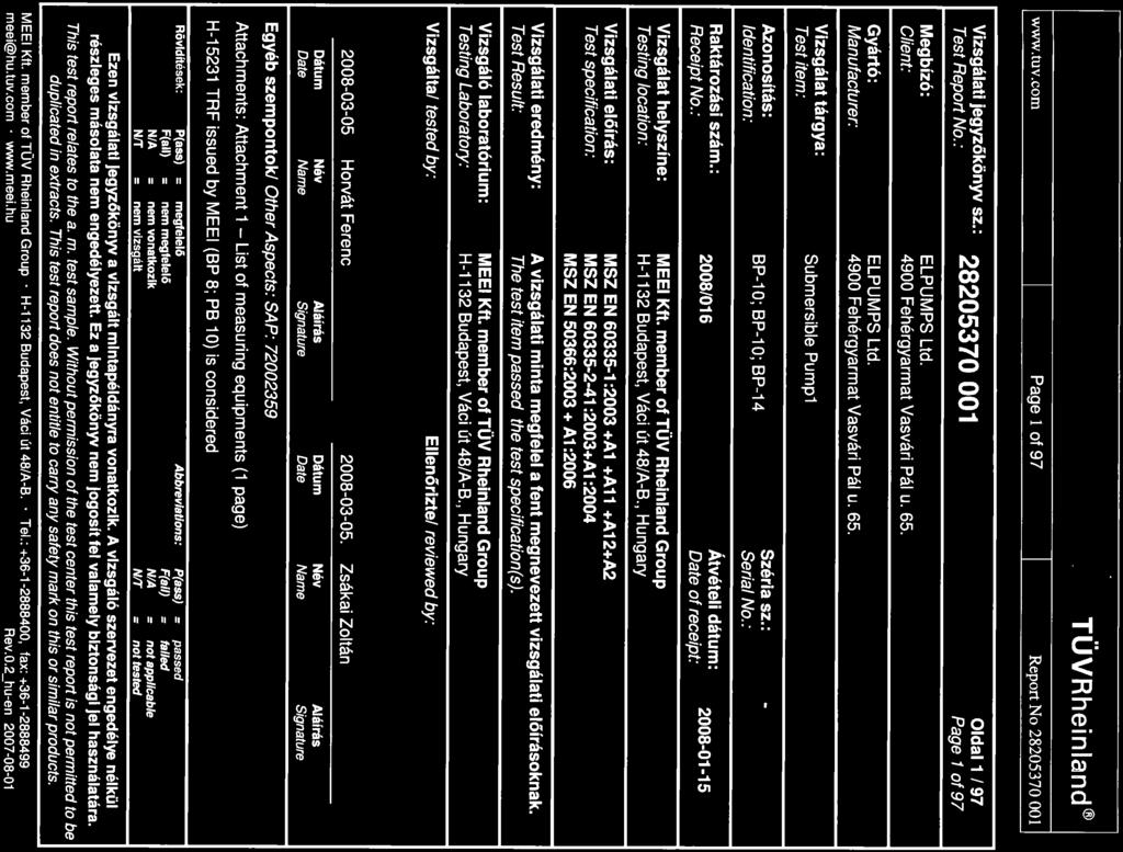
81
...: Horvát Ferenc See on page 1 Witnessed by (name + signature)...: Supervised by (name + signature).")
82 age 2 of 97 Report No TEST REORT Safety of household and similar electrical appliances art 2: articular requirements for pumps Report Reference No...: Tested by (name + signature)...: Horvát Ferenc See on page 1 Witnessed by (name + signature)...: Supervised by (name + signature)...: Zsákai Zoltán See on page 1 Approved by (name + signature)...: --- Date of issue...: CB Testing Laboratory...: Address...: Hungarian Institute for Testing and Certification of Electrical Equipment Ltd. (MEEI Ltd.) the member of TÜV Rheinland group H Budapest, Váci út 48. a-b Hungary Testing location/ procedure...: CBTL RMT SMT WM TM Type test Testing location/ address...: Applicant s name...: Hungarian Institute for Testing and Certification of Electrical Equipment Ltd. (MEEI Ltd.) the member of TÜV Rheinland group H Budapest, Váci út 48. a-b Hungary ELUMS Kft Address...: 4900 Fehérgyarmat Vasvári ál u. 65. Test specification: Standard...: Test procedure...: Non-standard test method..: Test Report Form No...: Test Report Form(s) Originator...: IEC :2002 (Third edition) + A1:2004 used in conjunction with IEC :2001 (Fourth Edition) modified + A1:2004+ A2:2006(added by MEEI) and/or EN : A1:2004 used in conjunction with EN : A11: A1:2004+A12:2006+A2:2006(added by MEEI) and EN 50366: A1:2006 Type test IECEN60335_2_41B VDE Master TRF...: Dated

83 age 3 of 97 Report No Copyright 2005 IEC System for Conformity Testing and Certification of Electrical Equipment (IECEE), Geneva, Switzerland. All rights reserved. This publication may be reproduced in whole or in part for non-commercial purposes as long as the IECEE is acknowledged as copyright owner and source of the material. IECEE takes no responsibility for and will not assume liability for damages resulting from the reader's interpretation of the reproduced material due to its placement and context. This report is not valid as a CB Test Report unless signed by an approved CB Testing Laboratory and appended to a CB Test Certificate issued by an NCB in accordance with IECEE 02. Test item description...: Submersible ump Trade Mark...: ELUMS Manufacturer...: ELUMS Kft 4900 Fehérgyarmat Vasvári ál u. 65. Model/Type reference...: B 8; B 10; B 14 Ratings...: 230V; 50Hz, 1400W (B 8; B10); 1600 W (B 14); IX8 Factory : ELUMS Kft 4900 Fehérgyarmat Vasvári ál u. 65. Copy of marking plate:


84 age 4 of 97 Report No Summary of testing: All applicable tests were performed and the test items passed the specifications. Tests were conducted on model: B 14 hotos:
85 age 5 of 97 Report No Test item particulars... : Classification of installation and use... : ortable Supply Connection... : Supply cord fitted with a plug... : -... : - ossible test case verdicts: - test case does not apply to the test object...: - test object does meet the requirement...: (ass) - test object does not meet the requirement...: F(Fail) Testing...: Date of receipt of test item...: Date (s) of performance of tests...: roduct verification per IECEE 02, Clause 6.2.5: - Steps taken by the NCB to ensure that the products - from all the factories stated in the CB Test Certificate are equal... General remarks: The test results presented in this report relate only to the object tested. This report shall not be reproduced, except in full, without the written approval of the Issuing testing laboratory. "(see Enclosure #)" refers to additional information appended to the report. "(see appended table)" refers to a table appended to the report. Throughout this report a comma (point) is used as the decimal separator. General product information / Additional remarks : The basic part of this report covers the assessment of the general IEC requirements. The AENDIX 1 includes the assessment of all group differences and national deviations to complete the assessment for CENELEC countries (according the last valid edition of the CB-Bulletin and the relevant EN standards). The AENDIX 2 includes all tables with the test results and photos of the appliances. The AENDIX 3 (if any) includes the assessment of further national differences as requested by the applicant (according to the last valid edition of the CB-Bulletin).
86 age 6 of 97 Report No GENERAL CONDITIONS FOR THE TESTS Tests performed according to cl. 5, e.g. nature of supply, sequence of testing, etc. 5.2 If the test of Annex D has to be carried out, an additional appliance may be used. (IEC /A1) 5.3 The tests of Clause 14 and 21.2 and are carried out after the tests of Clause 29. (IEC /A1) 5.7 Temperature of liquid is maintained within +0, -5K of the temperaturemarked on the pumb. (IEC ) 5.14 NOTE: Guidance is given in Annex for enhanced requirements that may be used to ensure an acceptable level of protection against electrical and thermal hazards for particular types of appliances used in an installation without a protective earthing conductor in countries that have warm damp equable climates. (IEC /A1) umps are tested as portable appliances, unless they are intended to be fixed (IEC ) Stationary pumps having a three-phase motor which does not incorporate a protective device are installed with an appropiate device, in accordance with the instructions (IEC ) 6 CLASSIFICATION 6.1 rotection against electric shock: I. Class 0, 0I, I, II, III... Submersible pumps for use in swimming pools when persons are in the pool shall be of class III with a rated voltage < 12V (IEC )
87 age 7 of 97 Report No Other submersible pumps for use in water and other conducting liquids shall be of class I or class III. However, aquarium pumps may be of class II (IEC ) ortable pumps for cleaning and other maintenance of swimming pools shall be of class I or class III (IEC ) Other pumps shall be class I, class II or class III (IEC ) Table fountain pumps for indoor use may also be class II as long as their rated power input does not exceed 25 W. (IEC /A1) I. 6.2 Submersible pumps shall be at least I X8 (IEC ) ortable pumps for cleaning and other maintenance of swimming pools shall be at least I X7 (IEC ) Other pumps shall be at least I X4 (IEC ) Shower-boost pumps intended for installation outside of zones 1 and 2, as specified in IEC , shall be at least IX2. (IEC /A1) I X8 7 MARKING AND INSTRUCTIONS 7.1 Rated voltage or voltage range (V) V Nature of supply... - Rated frequency (Hz) Hz Rated power input (W): ; 1600 W Rated current (A)... - Manufacturer's or responsible vendor's name, ELUMS trademark or identification mark... Model or type reference... B 8; B 10; B 14 Symbol 5172 of IEC 60417, for Class II appliances I number, other than IX0... I X8
88 age 8 of 97 Report No The enclosure of electrically-operated water valves incorporated in external hose-sets for connection of an appliance to the water mains shall be marked with symbol IEC (DB: ) if their working voltage exceeds extra-low voltage. (IEC /A1) umps having a rated power input exceeding 50 W shall be marked with: (IEC ) -the minimum total head in metres, if > 0 metres) (IEC ) -the maximum operating depth in metres, if > 1 metres (for submersible pumps) (IEC ) -the direction of rotation (three phase motor only) (IEC ) umps shall be marked with the maximum liquid temperature, which shall not be less than 35 C. (IEC ) If the temperature exceeds 35 C, they shall be marked with the maximum period of operation, unless they are intended for continuous operation. (IEC ) 7.2 Warning for stationary appliances for multiple supply Warning placed in vicinity of terminal cover 7.3 Range of rated values marked with the lower and upper limits separated by a hyphen Different rated values marked with the values separated by an oblique stroke 7.4 Appliances adjustable for different rated voltages, the voltage setting is clearly discernible 7.5 Appliances with more than one rated voltage or one or more rated voltage ranges, marked with rated input or rated current for each rated voltage or range, unless the power input is related to the mean value of the rated voltage range 10 m
89 age 9 of 97 Report No Relation between marking for upper and lower limits of rated power input or rated current and voltage is clear 7.6 Correct symbols used [symbol IEC (DB: )] equipotentiality (IEC /A1) symbol IEC (DB: )] dangerous voltage (IEC /A1) 7.7 Connection diagram fixed to appliances to be connected to more than two supply conductors and appliances for multiple supply 7.8 Except for type Z attachment, terminals for connection to the supply mains indicated as follows: - marking of terminals exclusively for the neutral conductor (N) - marking of protective earthing terminals (symbol 5019 of IEC 60417) - marking not placed on removable parts 7.9 Marking or placing of switches which may cause a hazard 7.10 Indications of switches on stationary appliances - and controls on all appliances by use of figures, letters or other visual means... The figure 0 indicates only OFF position, unless no confusion with the OFF position 7.11 Indication for direction of adjustment of controls 7.12 Instructions for safe use provided The instruction for use of class I portable pumps for cleaning and other maintenance of swimming pools shall include the substance of the following: (IEC ) -the pump must not be used when people are staying in the water (IEC ) -the pump must supplied through a residual current device (RCD) with a rated residual operating current < 30 ma (IEC )
90 age 10 of 97 Report No The instructions for use for pumps marked with a temperature exceeding 35 C shall state the maximum period of operation and the minimum rest period, unless the pump is intended for continuous operation at this temperature. (IEC ) Sufficient details for installation supplied The installation instruction shall provide information on requirements specified for the electrical installation and shall include reference to national wiring rules If reference is made to zones, the corresponding shall be included The installation instruction shall state the substance of the following: (IEC ) - the maximum total head, in meters (for pumps having a rated power input >50W) (IEC ) - pollution of the liquid could occur due to leakage of lubricants (for submersible pumps and vertical wet pit pumps contaiming lubricants) (IEC ) - Additional information for installation of stationary pumps having a three-phase motor not incorporating a protective device as specified (IEC ) The instructions for installation shall state that pumps for outdoor fountains, garden ponds and similar places have to be supplied through a RCD (operating current < 30 ma) (IEC ) The instructions for installation shall give full informations for installation of class I pumps for operating in swimming pools as specified (IEC ) The installation instructions for class III pumps intended to be installed in zone 0 of a swimming pool shall state that the transformer is located outside zone1 (IEC )
91 age 11 of 97 Report No The installation instructions for class II pumps intended to be fixed in zone 1 of a swimming pool, or fixed close to a garden pond or similar place, shall state that the pump is to be located where flooding cannot occur (IEC ) Stationary appliances not fitted with means for disconnection from the supply mains having a contact separation in all poles that provide full disconnection under overvoltage category III, the instructions state that means for disconnection must be incorporated in the fixed wiring in accordance with the wiring rules Insulation of the fixed wiring in contact with parts exceeding 50 K during clause 11; instructions stating that the fixed wiring must be protected Instructions for built-in appliances: - dimensions of space - dimensions and position of supporting means - distances between parts and surrounding structure - dimensions of ventilation openings and arrangement - connection to supply mains and interconnection of separate components - necessity to allow disconnection of the appliance from the supply after installation, unless the appliance incorporates a switch complying with (IEC /A1) The disconnection may be achieved by having the plug accessible or by incorporating a switch in the fixed wiring in accordance with the wiring rules. (IEC /A1) Replacement cord instructions, type X attachment with a specially prepared cord Replacement cord instructions, type Y attachment Replacement cord instructions, type Z attachment
92 age 12 of 97 Report No The instructions for heating appliances incorporating a non-self-resetting thermal cut-out that is reset by disconnection of the supply mains shall contain the substance of the following: (IEC /A1) CAUTION: In order to avoid a hazard due to inadvertent resetting of the thermal cut-out, this appliance must not be supplied through an external switching device, such as a timer, or connected to a circuit that is regularly switched on and off by the utility. (IEC /A1) The instructions for fixed appliances shall state how the appliance is to be fixed to its support. (IEC /A1) The instructions for appliances connected to the water mains shall state (IEC /A1) - the maximum inlet water pressure, in pascals; (IEC /A1) - the minimum inlet water pressure, in pascals, if this is necessary for the correct operation of the appliance. (IEC /A1) The instructions for appliances connected to the water mains by detachable hose-sets shall state that the new hose-sets supplied with the appliance are to be used and that old hosesets should not be reused. (IEC /A1) 7.13 Instructions and other texts in an official language 7.14 Marking clearly legible and durable 7.15 Marking on a main part Marking clearly discernible from the outside, if necessary after removal of a cover For portable appliances, cover can be removed or opened without a tool For stationary appliances, name, trademark or identification mark and model or type reference visible after installation
93 age 13 of 97 Report No For fixed appliances, name, trademark or identification mark and model or type reference visible after installation according to the instructions Indications for switches and controls placed on or near the components. Marking not on parts which can be positioned or repositioned in such a way that the marking is misleading 7.16 Marking of a possible replaceable thermal link or fuse link clearly visible with regard to replacing the link 8 ROTECTION AGAINST ACCESS TO LIVE ARTS 8.1 Adequate protection against accidental contact with live parts Requirement applies for all positions, detachable parts removed Insertion or removal of lamps, protection against contact with live parts of the lamp cap Use of test probe B of IEC 61032: no contact with live parts Use of test probe 13 of IEC through openings in class 0 appliances and class II appliances/ constructions: no contact with live parts Test probe 13 also applied through openings in earthed metal enclosures having a nonconductive coating: no contact with live parts For appliances other than class II, use of test probe 41 of IEC 61032: no contact with live parts of visible glowing heating elements Accessible part not considered live if: - safety extra-low a.c. voltage: peak value not exceeding 42.4 V - safety extra-low d.c. voltage: not exceeding 42.4 V - or separated from live parts by protective impedance
94 age 14 of 97 Report No If protective impedance: d.c. current not exceeding 2 ma, and a.c. peak value not exceeding 0.7 ma - for peak values over 42.4 V up to and including 450 V, capacitance not exceeding 0,1 µf - for peak values over 450 V up to and including 15 kv, discharge not exceeding 45 µc The quantity of electricity in the discharge is measured using a resistor having a nominal non-inductive resistance of (IEC /A1) Live parts protected at least by basic insulation before installation or assembly: - built-in appliances - fixed appliances - appliances delivered in separate units 8.2 Class II appliances and constructions constructed so that there is adequate protection against accidental contact with basic insulation and metal parts separated from live parts by basic insulation only Only possible to touch parts separated from live parts by double or reinforced insulation 9 STARTING OF MOTOR-OERATED ALIANCES Requirements and tests are specified in part 2 when necessary 10 OWER INUT AND CURRENT 10.1 ower input at normal operating temperature, rated voltage and normal operation not deviating from rated power input by more than shown in table Current at normal operating temperature, rated voltage and normal operation not deviating from rated current by more than shown in table 2
95 age 15 of 97 Report No HEATING 11.1 No excessive temperatures in normal use 11.2 lacing and mounting of appliance as described 11.3 Temperature rises, other than of windings, determined by thermocouples Temperature rises of windings determined by resistance method, unless the windings makes it difficult to make the necessary connections By resistance 11.4 Heating appliances operated under normal operation at 1.15 times rated power input..: 11.5 Motor-operated appliances operated under normal operation at most unfavourable voltage between 0.94 and 1.06 times rated voltage : 11.6 Combined appliances operated under normal operation at most unfavourable voltage between 0.94 and 1.06 times rated voltage : 11.7 umps are operated with the liquid maintained at the temperature marked on the pump. (IEC /A1) They are operated until steady conditions are established unless they are marked with a maximum period of operation. In this case, they are operated for the marked period followed by the rest period specified in the instructions, the test being carried out for three cycles of operation. (IEC /A1) Shower-boost pumps that are also supplied with cold water are operated with the cold water at 15 ºC ± 2 ºC. (IEC /A1) umps, other than shower-boost pumps, marked with a maximum period of operation are also operated with the liquid maintained at 35 ºC until steady conditions are established. (IEC /A1) x -
96 age 16 of 97 Report No If the pumb is marked with a maximum period of operation- - the liquid temperature is 35 C instead of the marked temperature; it is also operated for this period followed by the rest period specified in the instructions for use, the liquid being maintained at the marked temperature. This test is carried out for three cycles of operation. (IEC ) 11.8 Temperature rises not exceeding values in table 3 rotective devices do not operate However, components in protective electronic circuits are allowed to operate provided they are tested for the number of cycles of operation specified in (IEC /A1) The temperature rise limit does not apply to switches or controls tested in accordance with the conditions occurring in the appliance. (IEC /A1) Sealing compound does not flow out For pumps marked with a temperature exceeding 35 C, the temperature rise of the external enclosure is not measured. (IEC ) (see appended tables) 13 LEAKAGE CURRENT AND ELECTRIC STRENGTH AT OERATING TEMERATURE 13.1 Leakage current not excessive and electric strength adequate Heating appliances operated at 1.15 times - rated power input... Motor-operated appliances and combined 243,8 V appliances supplied at 1.06 times rated voltage... rotective impedance and radio interference filters disconnected before carrying out the tests
97 age 17 of 97 Report No Leakage current measured by means of the circuit described in figure 4 of IEC Leakage current measurements (see appended table) 13.3 The appliance is disconnected from the supply and the insulation is immediately subjected to a voltage having a frequency of 50 Hz or 60 Hz for 1 min, in accordance with IEC (IEC /A1) The high-voltage source used for the test is to be capable of supplying a short circuit current Is between the output terminals after the output voltage has been adjusted to the appropriate test voltage. (IEC /A1) The overload release of the circuit is not to be operated by any current below the tripping current Ir. The values of Is and Ir are given in Table 5 for various high-voltage sources. (IEC /A1) 14 TRANSIENT OVERVOLTAGES Appliances withstand the transient overvoltages to which they may be subjected Clearances having a value less than specified in table 16 subjected to an impulse voltage test, the test voltage specified in table 6 No flashover during the test, unless of functional insulation In case of flashover of functional insulation, the appliance complies with clause 19 with the clearance short circuited (see appended table) 15 MOISTURE RESISTANCE 15.1 Enclosure provides the degree of moisture protection according to classification of the appliance Compliance checked as specified in , taking into account , followed by the electric strength test of 16.3
98 age 18 of 97 Report No No trace of water on insulation which can result in a reduction of clearances and creepage distances below values specified in clause Appliances, other than IX0, subjected to tests I X8 as specified in IEC Water valves containing live parts and that are incorporated in external hoses for connection of an appliance to the water mains are subjected to the test specified for IX7 appliances. (IEC /A1) Shower-boost pumps are subjected to the appropriate test of IEC both at rest and in operation while supplied at rated voltage. (IEC /A1) Hand-held appliance turned continuously through the most unfavourable positions during the test Built-in appliances installed according to the instructions Appliances placed or used on the floor or table placed on a horizontal unperforated support Appliances normally fixed to a wall and appliances with pins for insertion into socketoutlets are mounted on a wooden board For IX3 appliances, the base of wall mounted appliances is placed at the same level as the pivot axis of the oscillating tube For IX4 appliances, the horizontal centre line of the appliance is aligned with the pivot axis of the oscillating tube However, for appliances normally used on the floor or table, the movement is limited to two times 90 for a period of 5 min, the support being placed at the level of the pivot axis of the oscillating tube Wall-mounted appliances, take into account the distance to the floor stated in the instructions
99 age 19 of 97 Report No Appliances normally fixed to a ceiling are mounted underneath a horizontal unperforated support that is constructed to prevent water spraying onto its top surface. The pivot axis of the oscillating tube is located at the same level as the underside of the support and aligned centrally with the appliance. The spray is directed upwards. (IEC /A1) For IX4 appliances, the movement of the tube is limited to two times 90º from the vertical for a period of 5 min. (IEC /A1) Appliances with type X attachment fitted with a flexible cord as described Detachable parts tested as specified I X4 pumps are tested as specified (IEC ) I X7-pumps (submersible pumps) are immersed for 24 h in water as specified (IEC ) 1,5 times the pressure occurring at the maximum operation depth, when this depth does not exceed 10m (IEC ) 1,3 times the pressure occurring at the maximum operating depth, or 15 m, if this is higher. (IEC /A1) 15.2 Spillage of liquid does not affect the electrical insulation Appliances with type X attachment fitted with a flexible cord as described Appliances incorporating an appliance inlet tested with or without an connector, whichever is most unfavourable Detachable parts removed Overfilling test with additional amount of - water, over a period of 1 min (l)... The appliance withstands the electric strength test of 16.3
100 age 20 of 97 Report No No trace of water on insulation that can result in a reduction of clearances and creepage distances below values specified in clause Appliances proof against humid conditions Humidity test for 48 h in a humidity cabinet (not for submersible pumps) (IEC ) The appliance withstands the tests of clause 16 controlling box 16 LEAKAGE CURRENT AND ELECTRIC STRENGTH 16.1 Leakage current not excessive and electric strength adequate rotective impedance disconnected from live parts before carrying out the tests 16.2 Single-phase appliances: test voltage ,8 V times rated voltage... Three-phase appliances: test voltage times rated voltage divided by 3... Leakage current measurements (see appended table) 16.3 Electric strength tests according to table 7 (see appended table) No breakdown during the tests 17 OVERLOAD ROTECTION OF TRANSFORMERS AND ASSOCIATED CIRCUITS No excessive temperatures in transformer or associated circuits in event of short-circuits likely to occur in normal use (see appended table) Appliance supplied with 1.06 or 0.94 times rated voltage and the most unfavourable shortcircuit or overload likely to occur in normal use applied... - Temperature rise of insulation of the conductors of safety extra-low voltage circuits not exceeding the relevant value specified in table 3 by more than 15 K Temperature of the winding not exceeding the value specified in table 8,
101 age 21 of 97 Report No however limits do not apply to fail-safe transformers complying with sub-clause 15.5 of IEC ENDURANCE Requirements and tests are specified in part 2 when necessary 19 ABNORMAL OERATION 19.1 The risk of fire or mechanical damage under abnormal or careless operation obviated Electronic circuits so designed and applied that a fault will not render the appliance unsafe umps are also subjected to the tests of and (IEC ) 19.2 Test of appliance with heating elements with restricted heat dissipation; test voltage (V): power input of 0.85 times rated power input Test of 19.2 repeated; test voltage (V): power input of 1.24 times rated power input Test conditions as in cl. 11, any control limiting the temperature during tests of cl. 11 short-circuited 19.5 Test of 19.4 repeated on Class 0I and I appliances with tubular sheathed or embedded heating elements. No short-circuiting, but one end of the element connected to the elements sheath The test repeated with reversed polarity and the other end of the heating element connected to the sheath The test is not carried out on appliances intended to be permanently connected to fixed wiring and on appliances where an all-pole disconnection occurs during the test of Appliances with TC heating elements tested at rated voltage, establishing steady conditions
102 age 22 of 97 Report No The working voltage of the TC heating element is increased by 5% and the appliance is operated until steady conditions are reestablished. The voltage is then increased in similar steps until 1.5 times working voltage or until the TC heating element ruptures 19.7 Stalling test by locking the rotor if the locked rotor torque is smaller than the full load torque or locking moving parts of other appliances Locked rotor, motor capacitors open-circuited or short-circuited, if required Locked rotor, capacitors open-circuited one at a time Test repeated with capacitors short-circuited one at a time, if required Appliances with timer or programmer supplied with rated voltage for each of the tests, for a period equal to the maximum period allowed Other appliances supplied with rated voltage for a period as specified Winding temperatures not exceeding values specified in table Three-phase motors operated at rated voltage with one phase disconnected (see appended table) Series motor operated at 1.3 times rated - voltage for 1 min... During the test, parts not being ejected from the appliance Electronic circuits, compliance checked by evaluation of the fault conditions specified in for all circuits or parts of circuits, unless they comply with the conditions specified in Appliances incorporating a protective electronic circuit are subjected to the tests of and (IEC /A1) Appliances having a switch with an off position obtained by electronic disconnection, or a switch that can place the appliance in a standby mode, are subjected to the tests of (IEC /A1)
103 age 23 of 97 Report No During and after each test the following is checked: - the temperature rise of the windings do not exceed the values specified in table 8 - the appliance complies with the conditions specified in any current flowing through protective impedance not exceeding the limits specified in If a conductor of a printed board becomes open-circuited, the appliance is considered to have withstood the particular test, provided all three of the following conditions are met: - the material of the printed circuit board withstands the burning test of annex E - any loosened conductor does not reduce the clearances or creepage distances between live parts and accessible metal parts below the values specified in cl the appliance withstands the tests of with open-circuited conductor bridged Before applying the fault conditions a) to f) in , it is checked if circuits or parts of circuit meet both of the following conditions: - the electronic circuit is a low-power circuit, that is, the maximum power at low-power points does not exceed 15 W according to the tests specified - the protection against electric shock, fire hazard, mechanical hazard or dangerous malfunction in other parts of the appliance does not rely on the correct functioning of the electronic circuit Fault conditions applied one at a time, the appliance operated under conditions specified in cl. 11, but supplied at rated voltage, the duration of the tests as specified: a) short circuit of functional insulation if clearances or creepage distances are less than the values specified in 29 b) open circuit at the terminals of any component
104 age 24 of 97 Report No c) short circuit of capacitors, unless they comply with IEC d) short circuit of any two terminals of an electronic component, other than integrated circuits. This fault condition is not applied between the two circuits of an optocoupler e) failure of triacs in the diode mode f) failure of an integrated circuit. In each case, the test is ended if a non-selfresetting interruption of the supply occurs within the appliance. (IEC /A1) If the appliance incorporates a protective electronic circuit which operates to ensure compliance with clause 19, the relevant test is repeated with a single fault simulated, as indicated in a) to f) of Appliances having a switch with an off position obtained by electronic disconnection, or a switch that can be placed in the stand-by mode, are subjected to the tests of to The tests are carried out with the appliance supplied at rated voltage, the switch being set in the off position or in the stand-by mode. (IEC /A1) Appliances incorporating a protective electronic circuit are subjected to the tests of to The tests are carried out after the protective electronic circuit has operated during the relevant tests of Clause 19 except 19.2, 19.6 and However, appliances that are operated for 30 s or 5 min during the test of 19.7 are not subjected to the tests for electromagnetic phenomena. (IEC /A1) The tests are carried out with surge arresters disconnected, unless they incorporate spark gaps (IEC /A1) The appliance is subjected to electrostatic discharges in accordance with IEC , test level 4 being applicable. Ten discharges having a positive polarity and ten discharges having a negative polarity are applied at each preselected point (IEC /A1)
105 age 25 of 97 Report No The appliance is subjected to radiated fields in accordance with IEC , test level 3 being applicable. (IEC /A1) The appliance is subjected to fast transient bursts in accordance with IEC Test level 3 s applicable for signal and control lines. Test level 4 is applicable for the power supply lines. The bursts are applied for 2 min with a positive polarity and for 2 min with a negative polarity (IEC /A1) The power supply terminals of the appliance are subjected to voltage surges in accordance with IEC , five positive impulses and five negative impulses being applied at the selected points. Test level 3 is applicable for the line-to-line coupling mode, a generator having a source impedance of 2 Ω being used. Test level 4 is applicable for the line-toearth coupling mode, a generator having a source impedance of 12 Ω being used. (IEC /A1) Earthed heating elements in class I appliances are disconnected during this test (IEC /A1) For appliances having surge arresters incorporating spark gaps, the test is repeated at a level that is 95 % of the flashover voltage (IEC /A1) The appliance is subjected to injected currents in accordance with IEC , test level 3 being applicable. During the test, all frequencies between 0,15 MHz to 80 MHz are covered. (IEC /A1) The appliance is subjected to voltage dips and interruptions in accordance with IEC The durations specified in Table 1 of IEC are applied to each test level, the dips and interruptions being applied at zero crossing of the supply voltage (IEC /A1) The appliance is subjected to mains signals in accordance with IEC , test level class 2 being applicable (IEC /A1)
106 age 26 of 97 Report No If the safety of the appliance for any of the fault conditions specified in depends on the operation of a miniature fuse-link complying with IEC 60127, the test is repeated, measuring the current flowing through the fuse-link; measured current (A); rated current of the fuselink (A) During the tests the appliance does not emit flames, molten metal, poisonous or ignitable gas in hazardous amounts Temperature rises not exceeding the values shown in table 9 Enclosures not deformed to such an extent that compliance with cl. 8 is impaired If the appliance can still be operated it complies with 20.2 The appliance shall not undergo a dangerous malfunction, and there shall be no failure of protective electronic circuits if the appliance is still operable. (IEC /A1) Appliances tested with an electronic switch in the off position, or in the stand-by mode, shall not become operational (IEC /A1) Insulation, other than of class III appliance, withstand the electric strength test of 16.3, the test voltage specified in table 4: - basic insulation V - supplementary insulation V - reinforced insulation V The pump is supplied at rated voltage and operated at approximately half at the maximum total head for 5 min, (IEC ) After which the inlet is removed from the liquid and the operation continued for 7h (IEC ) umps are operated again for 5 min at approximately half the maximum total head (IEC )
107 age 27 of 97 Report No If the pump becomes inoperable during the test., it is disconnected from the supply and filled with water (IEC ) umps marked with a maximum period of operation are supplied at rated voltage and operated under normal operation until steady conditions are established. (IEC ) 20 STABILITY AND MECHANICAL HAZARDS 20.1 Adequate stability Submersible pumps are not subjected to the test (IEC ) Tilting test through an angle of 10 (appliance placed on an inclined plane/horizontal plane); appliance does not overturn Tilting test repeated on appliances with heating elements, angle of inclination increased to 15 ossible heating test in overturned position; temperature rise does not exceed values shown in table Moving parts adequately arranged or enclosed as to provide protection against personal injury rotective enclosures, guards and similar parts are non-detachable Adequate mechanical strength and fixing of protective enclosures Self-resetting thermal cut-outs and overcurrent protective devices not causing a hazard, by unexpected reclosure Not possible to touch dangerous moving parts with test probe 21 MECHANICAL STRENGTH Appliance has adequate mechanical strength and is constructed as to withstand rough handling
108 age 28 of 97 Report No Compliance is checked by applying blows to the appliance in accordance with test Ehb of IEC , the spring hammer test. (IEC /A1) The appliance is rigidly supported and three blows, having an impact energy of 0,5 J, are applied to every point of the enclosure that is likely to be weak. (IEC /A1) For pumps, other than shower-boost pumps, the impact energy is increased to 1,0 J. No damage after three blows applied to various parts of the enclosure (IEC ) If necessary, repetition of groups of three blows on a new sample If necessary, supplementary or reinforced insulation subjected to the electric strength test of Accessible parts of solid insulation shall have sufficient strength to prevent penetration by sharp implements. (IEC /A1) Compliance is checked by subjecting the insulation to the following test, unless the thickness of supplementary insulation is at least 1 mm and that of reinforced insulation is at least 2 mm. (IEC /A1) The insulation is raised to the temperature measured during the test of Clause 11. (IEC /A1) The surface of the insulation is then scratched by means of a hardened steel pin, the end of which has the form of a cone with an angle of 40 : Its tip is rounded with a radius of 0,25 mm ± 0,02 mm. (IEC /A1) The pin is held at an angle of to the horizontal and loaded so that the force exerted along its axis is 10 N ± 0,5 N. (IEC /A1) The scratches are made by drawing the pin along the surface of the insulation at a speed of approximately 20 mm/s. Two parallel scratches are made. (IEC /A1) 2 mm
109 age 29 of 97 Report No They are spaced sufficiently apart so that they are not affected by each other, their length covering approximately 25 % of the length of the insulation. (IEC /A1) Two similar scratches are made at 90o to the first pair without crossing them. (IEC /A1) The test fingernail of Figure 7 is then applied to the scratched surface with a force of approximately 10 N. No further damage, such as separation of the material, shall occur. The insulation shall then withstand the electric strength test of (IEC /A1) The hardened steel pin is then applied perpendicularly with a force of 30 N 0,5 N to an unscratched part of the surface. The insulation shall then withstand the electric strength test of 16.3 with the pin still applied and used as one of the electrodes. (IEC /A1) 22 CONSTRUCTION 22.1 Appliance marked with the first numeral of the I system, relevant requirements of IEC are fulfilled 22.2 Stationary appliance: means to provide all-pole disconnection from the supply provided, the following means being available: - a supply cord fitted with a plug - a switch complying with a statement in the instruction sheet that a disconnection incorporated in the fixed wiring is to be provided - an appliance inlet Singe-pole switches and single-pole protective devices for the disconnection of heating elements in single-phase permanently connected class I appliances, connected in the phase conductor 22.3 Appliance provided with pins: no undue strain on socket-outlets
110 age 30 of 97 Report No Applied torque not exceeding 0.25 Nm ull force of 50N to each pin after the appliance has being placed in the heating cabinet; when cooled to room temperature the pins are not displaced by more than 1mm Each pin subjected to a tork of 0.4Nm; the pins are not rotating unless rotating does not impair compliance with the standard 22.4 Appliance for heating liquids and appliance causing undue vibration not provided with pins for insertion into socket-outlets 22.5 No risk of electric shock when touching the pins of the plug The appliance is supplied at rated voltage. Any switch is then placed in the off position and the appliance is disconnected from the supply mains at the instant of voltage peak. One second after disconnection, the voltage between the pins of the plug is measured with an instrument that does not appreciably affect the value to be measured. (IEC /A1) The voltage shall not exceed 34 V 22.6 Electrical insulation not affected by condensing water or leaking liquid Compliance is checked by inspection and for pumps of class II by the test with removal seal of the pump shaft as specified (IEC ) Electrical insulation of Class II appliances not affected in case of a hose rupture or seal leak Shower-boost pumps having a separate enclosure shall have a drain hole in the enclosure positioned so that the water can drain out without impairing electrical insulation, unless water cannot accumulate within the enclosure in normal use. (IEC ) The hole shall be at least 5 mm in diameter or 20 mm 2 in area with a width of least 3 mm. (IEC )
111 age 31 of 97 Report No Adequate safeguards against the risk of excessive pressure in appliances provided with steam-producing devices 22.8 Electrical connections not subject to pulling during cleaning of compartments to which access can be gained without the aid of a tool, and that are likely to be cleaned in normal use 22.9 Insulation, internal wiring, windings, commutators and slip rings not exposed to oil, grease or similar substances Adequate insulating properties of oil or grease to which insulation is exposed It shall not be possible to reset voltagemaintained non-self-resetting thermal cut-outs by the operation of an automatic switching device incorporated within the appliance. (IEC /A1) NOTE 1 : Voltage-maintained controls will automatically reset if they become deenergized (IEC /A1) Non-self-resetting thermal motor protectors shall have a trip-free action unless they are voltage maintained. (IEC /A1) NOTE 2: Trip-free is an automatic action that is independent of manipulation or position of the actuating member. (IEC /A1) Reset buttons of non-self-resetting controls shall be located or protected so that their accidental resetting is unlikely to occur if this could result in a hazard. (IEC /A1) NOTE 3: For example, this requirement precludes the location of reset buttons on the back of an appliance, which could result in them being reset by pushing the appliance against a wall. (IEC /A1) Reliable fixing of non-detachable parts that provide the necessary degree of protection against electric shock, moisture or contact with moving parts Obvious locked position of snap-in devices used for fixing such parts
112 age 32 of 97 Report No No deterioration of the fixing properties of snapin devices used in parts that are likely to be removed during installation or servicing Tests as described Handles, knobs etc. fixed in a reliable manner Fixing in wrong position of handles, knobs etc. indicating position of switches or similar components not possible Axial force 15 N applied to parts, the shape being so that an axial pull is unlikely to be applied Axial force 30 N applied to parts, the shape being so that an axial pull is likely to be applied Unlikely that handles, when gripped as in normal use, make the operators hand touch parts having a temperature rise exceeding the value specified for handles which are held for short periods only No ragged or sharp edges creating a hazard for the user in normal use, or during user maintenance No exposed pointed ends of self tapping screws etc., liable to be touched by the user in normal use or during user maintenance Storage hooks and the like for flexible cords smooth and well rounded Automatic cord reels cause no undue abrasion or damage to the sheath of the flexible cord, no breakage of conductors strands, no undue wear of contacts Cord reel tested with 6000 operations, as specified Electric strength test of 16.3, voltage of 1000 V applied Spacers not removable from the outside by hand or by means of a screwdriver or a spanner Current-carrying parts and other metal parts resistant to corrosion under normal conditions of use
113 age 33 of 97 Report No Current-carrying parts and other metal parts resistant to corrosion under normal conditions of use. Direct contact between opper and aluminium or their alloys is to be avoided (IEC ) Driving belts not used as electrical insulation Direct contact between live parts and thermal insulation effectively prevented, unless material used is non-corrosive, non-hygroscopic and non-combustible Compliance is checked by inspection and, if necessary, by appropriate test Wood, cotton, silk, ordinary paper and fibrous or hygroscopic material not used as insulation, unless impregnated Appliances not containing asbestos Oils containing polychlorinated biphenyl (CB) not used Bare heating elements adequately supported In case of rupture, the heating conductor is unlikely to come in contact with accessible metal parts Sagging heating conductors cannot come into contact with accessible metal parts The insulation between parts operating at safety extra-low voltage and other live parts complies with the requirements for double or reinforced insulation arts connected by protective impedance separated by double or reinforced insulation Metal parts of Class II appliances conductively connected to gas pipes or in contact with water: separated from live parts by double or reinforced insulation Class II appliances permanently connected to fixed wiring so constructed that the required degree of access to live parts is maintained after installation arts serving as supplementary or reinforced insulation fixed so that they cannot be removed without being seriously damaged, or
114 age 34 of 97 Report No so constructed that they cannot be replaced in an incorrect position, and so that if they are omitted, the appliance is rendered inoperable or manifestly incomplete Clearances and creepage distances over supplementary and reinforced insulation not reduced below values specified for supplementary insulation Creepage distances and clearances over supplementary or reinforced insulation not reduced to less than 50% of values specified in 29 if wires, screws etc. become loose Supplementary and reinforced insulation designed or protected against deposition of dirt or dust Supplementary insulation of natural or synthetic rubber resistant to ageing, or arranged and dimensioned so that creepage distances are not reduced below values specified in 29.2 Ceramic material not tightly sintered, similar material or beads alone not used as supplementary or reinforced insulation Oxygen bomb test at 70 C for 96 h and 16 h at room temperature Conductive liquids that are or may become accessible in normal use are not in direct contact with live parts Electrodes not used for heating liquids For class II constructions, conductive liquids that are or may become accessible in normal use, not in direct contact with basic or reinforced insulation For class II constructions, conductive liquids which are in contact with live parts, not in direct contact with reinforced insulation Shafts of operating knobs, handles, levers etc. not live, unless the shaft is not accessible when the part is removed Handles, levers and knobs, held or actuated in normal use, not becoming live in the event of an insulation fault
115 age 35 of 97 Report No Such parts being of metal, and their shafts or fixings are likely to become live in the event of an insulation fault, they are either adequately covered by insulation material, or their accessible parts are separated from their shafts or fixings by supplementary insulation This requirement does not apply to handles, levers and knobs on stationary appliances other than those of electrical components, provided they are either reliably connected to an earthing terminal or earthing contact, or separated from live parts by earthed metal Handles continuously held in the hand in normal use are so constructed that when gripped as in normal use, the operators hand is not likely to touch metal parts, unless they are separated from live parts by double or reinforced insulation Capacitors in Class II appliances not connected to accessible metal parts, unless complying with Metal casings of capacitors in Class II appliances separated from accessible metal parts by supplementary insulation, unless complying with Capacitors not connected between the contacts of a thermal cut-out Lamp holders used only for the connection of lamps Motor-operated appliances and combined appliances intended to be moved while in operation, or having accessible moving parts, fitted with a switch to control the motor. The actuating member of the switch being easily visible and accessible The requirement is not applicable to submersible pumps and vertical wet pit pumps (IEC ) No components, other than lamps, containing mercury rotective impedance consisting of at least two separate components
116 age 36 of 97 Report No Values specified in not exceeded if any one of the components are short-circuited or open-circuited Appliances adjustable for different voltages, accidental changing of the setting of the voltage unlikely to occur Appliances are not allowed to have an enclosure that is shaped and decorated so that the appliance is likely to be treated as a toy by children When air is used as reinforced insulation, clearances not reduced below the values specified in due to deformation as a result of an external force applied to the enclosure Software used in protective electronic circuits shall be software class B or software class C (IEC /A1) NOTE 1: Failure of software class B in the presence of another fault in the appliance, or failure of software class C alone, could result in dangerous malfunction, electric shock, fire, mechanical or other hazards. Software class A denotes software used for functional purposes. (IEC /A1) Compliance is checked by evaluating the software in accordance with Annex R. (IEC /A1) NOTE 2: If the software program is modified, the evaluation and relevant tests are repeated if the modification can influence the results of the test involving protective electronic circuits. (IEC /A1) Appliances intended to be connected to the water mains shall withstand the water pressure expected in normal use. (IEC /A1) Compliance is checked by connecting the appliance to a water supply having a static pressure equal to twice the maximum inlet water pressure or 1,2 Ma, whichever is higher, for a period of 5 min (IEC /A1)
117 age 37 of 97 Report No There shall be no leakage from any part, including any inlet water hose (IEC /A1) Appliances intended to be connected to the water mains shall be constructed to prevent backsiphonage of non-potable water into the water mains. (IEC /A1) Compliance is checked by the relevant tests of IEC (IEC /A1) umps shall withstand the static liquid pressure occuring in normal use as specified: (Submersible pumps and vertical wet pit pumps are not subjected to this test) (IEC ) The pressure test is carried out for 1 min at a pressure of 1,2 times the pressure occuring at maximum pump total head:... m (IEC ) The material of the pump shall not be affected by the liquid for which the pump is intended if a hazard could result (IEC ) Submersible pumps and vertical wet pit pumps shall be constructed so that pollution of liquid by lubricants is prevented as far as possible (IEC ) Submersible pumps and vertical wet pit pumps having a mass > 3 Kg shall be constructed so that means for hoisting can be attached (IEC ) Class I submersible pumps having a plastic enclosure shall be so constructed so that leakage of liquid into the motor does not result in a hazard (IEC ) After the specified test the accumulating water shall come in contact with earthed metal before it reaches live parts (IEC ) Shower-boost pumps shall be constructed so that they can be permanently connected to the water supply. (IEC /A1) Shower-boost pumps for wall mounting shall be constructed so that they can be securely fixed independently of the connection to the water supply. (IEC /A1) Water
118 age 38 of 97 Report No INTERNAL WIRING 23.1 Wireways smooth and free from sharp edges Wires protected against contact with burrs, cooling fins etc. Wire holes in metal well rounded or provided with bushings Wiring effectively prevented from coming into contact with moving parts 23.2 Beads etc. on live wires cannot change their position, and are not resting on sharp edges or corners Beads inside flexible metal conduits contained within an insulating sleeve 23.3 Electrical connections and internal conductors movable relatively to each other not exposed to undue stress Flexible metallic tubes not causing damage to insulation of conductors Open-coil springs not used Adequate insulating lining provided inside a coiled spring, the turns of which touch one another No damage after flexings for conductors flexed during normal use or 100 flexings for conductors flexed during user maintenance Electric strength test, 1000 V between live parts and accessible metal parts 23.4 Bare internal wiring sufficiently rigid and fixed 23.5 The insulation of internal wiring withstanding the electrical stress likely to occur in normal use No breakdown when a voltage of 2000 V is applied for 15 min between the conductor and metal foil wrapped around the insulation 23.6 Sleeving used as supplementary insulation on internal wiring retained in position by positive means
119 age 39 of 97 Report No The colour combination green/yellow used only for earthing conductors 23.8 Aluminium wires not used for internal wiring 23.9 No lead-tin soldering of stranded conductors where they are subject to contact pressure, unless clamping means so constructed that there is no risk of bad contact due to cold flow of the solder The insulation and sheath of internal wiring, incorporated in external hoses for the connection of an appliance to the water mains, shall be at least equivalent to that of light polyvinyl chloride sheathed flexible cord (code designation IEC 52). (IEC /A1) NOTE The mechanical characteristics specified in IEC are not evaluated (IEC /A1) 24 COMONENTS 24.1 Components comply with safety requirements in relevant IEC standards List of components (see appended table) Components not tested and found to comply with relevant IEC standard for the number of cycles specified are tested in accordance with to Components not tested and found to comply with relevant IEC standard, components not marked or not used in accordance with its marking, tested under the conditions occurring in the appliance Motors are not required to comply with IEC (IEC /A1) Capacitors likely to be permanently subjected to the supply voltage and used for radio interference suppression or for voltage dividing, complying with IEC , or tested according to annex F
120 age 40 of 97 Report No Safety isolating transformers complying with IEC , or tested according to annex G Switches complying with IEC , the number of cycles of operation being at least , or tested according to annex H Level switches are tested for cycles of operation (IEC ) Automatic controls complying with IEC with relevant part 2. The number of cycles of operation being: - thermostats: temperature limiters: self-resetting thermal cut-outs: voltage-maintained non-self-resetting thermal cut-outs: other non-self-resetting thermal cut-outs: 30 - timers: energy regulators: Thermal motor protectors are tested in combination with their motor under the conditions specified in Annex D. (IEC /A1) For water valves containing live parts and that are incorporated in external hoses for connection of an appliance to the water mains, the degree of protection provided by enclosures against harmful ingress of water declared for subclause of IEC shall be IX7 (IEC /A1) Appliance couplers complying with IEC However, appliances classified higher than IX0, the appliance couplers complying with IEC The relevant standard for interconnection couplers is IEC (IEC /A1)
121 age 41 of 97 Report No Small lamp holders similar to E10 lampholders complying with IEC 60238, the requirements for E10 lampholders being applicable 24.2 No switches or automatic controls in flexible cords No devices causing the protective device in the fixed wiring to operate in the event of a fault in the appliance No thermal cut-outs that can be reset by soldering Level switches may be incorporated in interconnection cords (IEC ) 24.3 Switches intended for all-pole disconnection of stationary appliances are directly connected to the supply terminals and having a contact separation in all poles, providing full disconnection under overvoltage category III conditions 24.4 lugs and socket-outlets for extra-low voltage circuits and heating elements, not interchangeable with plugs and socket-outlets listed in IEC or IEC or with connectors and appliance inlets complying with the standard sheets of IEC Capacitors in auxiliary windings of motors marked with their rated voltage and capacitance and used accordingly Capacitors in appliances for which is applicable and that are permanently connected in series with a motor winding, are of class 1 or 2 of IEC Voltage across capacitors in series with a motor winding does not exceed 1,1 times rated voltage, when the appliance is supplied at 1,1 times rated voltage under minimum load 24.6 Working voltage of motors connected to the supply mains and having basic insulation that is inadequate for the rated voltage of the appliance, not exceeding 42V. In addition, the motors are complying with the requirements of Annex I
122 age 42 of 97 Report No Hose-sets for the connection of appliances to the water mains shall comply with IEC They shall be supplied with the appliance. (IEC /A1) 25 SULY CONNECTION AND EXTERNAL FLEXIBLE CORDS 25.1 Submersible pumps, other than class III, shall be provided with a supply cord fitted with a plug (IEC ) 25.2 Appliance not provided with more than one means of connection to the supply mains Stationary appliance for multiple supply may be provided with more than one means of connection, provided electric strength test of 1250 V for 1 min between each means of connection causes no breakdown 25.3 Submersible pumps, other than class III, shall be provided with a flexible cord (IEC ) 25.4 Cable and conduit entries, rated current of appliance not exceeding 16 A, dimensions according to table 10 Introduction of conduit or cable does not reduce clearances or creepage distances below values specified in 29 interconnection cords 25.5 Method for assemble supply cord with the appliance: - type X attachment is not allowed for submersible pumps (IEC ) controlling box - type Y attachment interconnection cords - type Z attachment, allowed for pumps having a rated power input not exceeding 100W and for pumps for garden ponds (IEC ) Type X attachment, other than those with a specially prepared cord, not used for flat twin tinsel cords 25.6 lugs fitted with only one flexible cord
123 age 43 of 97 Report No Supply cord not lighter than: IEC 66 (for pumps intended for outdoor use having a rated input > 1000 W and portable pumps having a mass > 5 Kg) (IEC ) IEC 66 (for pumps intended for use in swimming pools other than class III pumps) (IEC ) IEC 57 (for fixed pumps having a rated input < 1000 W and portable pumps for outdoor use having a mass < 5 Kg) (IEC ) IEC 57 (for pumps for indoor use, except table fountain pumps and aquarium pumps, shower-boost pumps and class III pumps (IEC /A1) Temperature rise of external metal parts exceeding 75 K, VC cord not used, unless appliance so constructed that the supply cord is not likely to touch external metal parts in normal use, or the supply cord is appropriate for higher temperatures, type Y or type Z attachment used 25.8 Nominal cross-sectional area of supply cords 7,1 A; 1,0 mm 2 according to table 11; rated current (A); crosssectional area (mm²)... The supply cord of submersible pumps other than class III pumps intended for outdoor use shall have a length of at least 10 m (IEC ) 25.9 Supply cord not in contact with sharp points or edges Green/yellow core for earthing purposes in Class I appliance Conductors of supply cords not consolidated by lead-tin soldering where they are subject to contact pressure, unless clamping means so constructed that there is no risk of bad contacts due to cold flow of the solder
124 age 44 of 97 Report No Moulding the cord to part of the enclosure does not damage the insulation of the supply cord Inlet opening so shaped as to prevent damage to the supply cord Unless the enclosure at the inlet opening is of insulation material, a non-detachable lining or bushing complying with 29.3 for supplementary insulation provided If unsheathed supply cord, a similar additional bushing or lining is required, unless the appliance is class Supply cords adequately protected against excessive flexing ortable pumps, except table fountain pumps and aquarium pumps, are subjected to the test (EN /A1) Flexing test: - applied force (N) N - number of flexings The test does not result in: - short circuit between the conductors - breakage of more than 10% of the strands of any conductor - separation of the conductor from its terminal - loosening of any cord guard - damage, within the meaning of the standard, to the cord or the cord guard - broken strands piercing the insulation and becoming accessible Conductors of the supply cord relieved from strain, twisting and abrasion by use of cord anchorage The cord cannot be pushed into the appliance to such an extent that the cord or internal parts of the appliance can be damaged
125 age 45 of 97 Report No ull and torque test of supply cord, values shown in table 10: pull (N); torque (not on automatic cord reel) (Nm)... Max. 2 mm displacement of the cord, and conductors not moved more than 1 mm in the terminals Creepage distances and clearances not reduced below values specified in 29.1 ull: 30 N; Torque: 0,1N (controlling box) Cord anchorages for type X attachments constructed and located so that: - replacement of the cord is easily possible controlling box - it is clear how the relief from strain and the prevention of twisting are obtained - they are suitable for different types of cord - cord cannot touch the clamping screws of cord anchorage if these screws are accessible, unless separated from accessible metal parts by supplementary insulation - the cord is not clamped by a metal screw which bears directly on the cord - at least one part of the cord anchorage securely fixed to the appliance, unless part of a specially prepared cord - screws which have to be operated when replacing the cord do not fix any other component, if applicable - if labyrinths can be bypassed the test of is nevertheless withstood - for Class 0, 0I and I appliances: they are of insulating material or are provided with an insulating lining, unless a failure of the insulation of the cord does not make accessible metal parts live - for Class II appliances: they are of insulating material, or if of metal, they are insulated from accessible metal parts by supplementary insulation Adequate cord anchorages for type Y and Z attachment pump interconnection cords
126 age 46 of 97 Report No Cord anchorages only accessible with the aid of a tool, or so constructed that the cord can only be fitted with the aid of a tool Type X attachment, glands not used as cord anchorage in portable appliances Tying the cord into a knot or tying the cord with string not used Conductors of the supply cord for type Y and Z attachment adequately additionally insulated Space for supply cord for type X attachment or for connection of fixed wiring constructed to permit checking of conductors with respect to correct positioning and connection before fitting any cover, no risk of damage to the conductors when fitting the cover, no contact with accessible metal parts if a conductor becomes loose, etc Appliance inlet: For portable appliances, the uninsulated end of a conductor prevented from any contact with accessible metal parts, unless the end of the cord is such that the conductors are unlikely to slip free controlling box controlling box pump interconnection cords controlling box - live parts not accessible during insertion or removal - connector can be inserted without difficulty - the appliance is not supported by the connector - is not for cold conditions if temp. Rise of external metal parts exceeds 75 K, unless the supply cord is not likely to touch such metal parts Interconnection cords comply with the requirements for the supply cord, except as specified If necessary, electric strength test of 16.3
127 age 47 of 97 Report No Interconnection cords not detachable without the aid of a tool if compliance with the standard is impaired when they are disconnected Dimensions of pins compatible with the dimensions of the relevant socket-outlet. Dimensions of pins and engagement face in accordance with the relevant plug in IEC TERMINALS FOR EXTERNAL CONDUCTORS 26.1 Appliances provided with terminals or equally effective devices for connection of external conductors However, earthing terminals may be accessible if a tool is required to make the connections and means are provided to clamp the wire independently from its connection. (IEC /A1) Terminals only accessible after removal of a non-detachable cover 26.2 Appliances with type X attachment and appliances for connection to fixed wiring provided with terminals in which connections are made by means of screws, nuts or similar devices, unless the connections are soldered Screws and nuts serve only to clamp supply conductors, except internal conductors, if so arranged that they are unlikely to be displaced when fitting the supply conductors If soldered connections used, the conductor so positioned or fixed that reliance is not placed on soldering alone Soldering alone used, barriers provided, clearances and creepage distances satisfactory if the conductor becomes free at the soldered joint 26.3 Terminals for type X attachment and for connection to fixed wiring so constructed that the conductor is clamped between metal surfaces with sufficient contact pressure and without damaging the conductor controlling box
128 age 48 of 97 Report No Terminals for type X attachment and those for connection to fixed wiring so fixed that when tightening or loosening the clamping means: - the terminal does not loosen - internal wiring is not subjected to stress - clearances and creepage distances are not reduced below the values in 29 Compliance checked by inspection and by the test of subclause 8.6 of IEC , the torque applied being equal to two-thirds of the torque specified. Nominal diameter of thread (mm); screw category; torque (Nm)... 0, Terminals for type X attachment, except those with a specially prepared cord, and those for connection to fixed wiring, no special preparation of conductors required, and so constructed or placed that conductors prevented from slipping out 26.5 Terminals for type X attachment so located or shielded that if a wire of a stranded conductor escapes, no risk of accidental connection to other parts that result in a hazard Stranded conductor test, 8 mm insulation removed No contact between live parts and accessible metal parts and, for class II constructions, between live parts and metal parts separated from accessible metal parts by supplementary insulation only 26.6 Terminals for type X attachment and for connection to fixed wiring suitable for connection of conductors with required crosssectional area according to table 13; rated current (A); nominal cross-sectional area (mm²).. 7,1 A; 1,0 mm 2 Terminals only suitable for a specially prepared cord 26.7 Terminals for type X attachment accessible after removal of a cover or part of the enclosure 26.8 Terminals for the connection to fixed wiring, including the earthing terminal, located close to each other
129 age 49 of 97 Report No Terminals of the pillar type constructed and located as specified Terminals with screw clamping and screwless terminals not used for flat twin tinsel cords, unless conductors ends fitted with a device suitable for screw terminals ull test of 5 N to the connection For type Y and Z attachment: soldered, welded, crimped and similar connections may be used For Class II appliances: the conductor so positioned or fixed that reliance is not placed on soldering, welding or crimping alone For Class II appliances: soldering, welding or crimping alone used, barriers provided, clearances and creepage distances satisfactory if the conductor becomes free pump interconnection cords 27 ROVISION FOR EARTHING 27.1 Accessible metal parts of Class 0I and I appliances, permanently and reliably connected to an earthing terminal or contact of the appliance inlet Earthing terminals not connected to neutral terminal Class 0, II and III appliance have no provision for earthing Safety extra-low voltage circuits not earthed, unless protective extra-low voltage circuits 27.2 Clamping means adequately secured against accidental loosening Terminals used for the connection of external equipotential bonding conductors allow connection of conductors of 2.5 to 6 mm², and do not provide earthing continuity between different parts of the appliance Conductors cannot be loosened without the aid of a tool
130 age 50 of 97 Report No For appliances with supply cord, currentcarrying conductors become taut before earthing conductor, if the cord slips out of the cord anchorage If a detachable part having an earth connection is plugged into another part of the appliance, the earth connection shall be made before the current-carrying connections are established. The current-carrying connections shall be separated before the earth connection when removing the part. (IEC /A1) 27.4 No risk of corrosion resulting from contact between metal of earthing terminal and other metal Adequate resistance to corrosion of coated or uncoated parts providing earthing continuity, other than parts of a metal frame or enclosure arts of steel providing earthing continuity provided at the essential areas with an electroplated coating, thickness at least 5 µm Adequate protection against rusting of parts of coated or uncoated steel, only intended to provide or transmit contact pressure In case of aluminium alloys precautions taken to avoid risk of corrosion 27.5 Low resistance of connection between earthing terminal and earthed metal parts This requirement does not apply to connections providing earthing continuity in the protective extra-low voltage circuit, provided that clearances of basic insulation are based on the rated voltage of the appliance Resistance not exceeding 0,1 at the specified low-resistance test 27.6 The printed conductors of printed circuit boards not used to provide earthing continuity in hand held appliances They may be used in other appliances if: - at least two tracks are used with independent soldering points and the appliance complies with requirements of 27.5 for each circuit
131 age 51 of 97 Report No the material of the printed circuit board complies with IEC or IEC SCREWS AND CONNECTIONS 28.1 Fixings, electrical connections and connections providing earthing continuity withstand mechanical stresses Screws not of soft metal liable to creep, such as zinc or aluminium Diameter of screws of insulating material min. 3 mm Screws of insulating material not used for any electrical connection or connections providing earthing continuity Screws used for electrical connections or connections providing earthing continuity screw into metal Screws not of insulating material if their replacement by a metal screw can impair supplementary or reinforced insulation Type X attachment, screws to be removed for replacement of supply cord or for user maintenance, not of insulating material if their replacement by a metal screw can impair basic insulation For screws and nuts; test as specified (see appended table) 28.2 Electrical connections and connections providing earthing continuity constructed so that contact pressure not transmitted through insulating material liable to shrink or distort, unless shrinkage or distortion compensated This requirement does not apply to electrical connections in circuits carrying a current not exceeding 0.5A 28.3 Space-threaded (sheet metal) screws only used for electrical connections if they clamp the parts together
132 age 52 of 97 Report No Thread-cutting (self-tapping) screws only used for electrical connections if they generate a full form standard machine screw thread Such screws not used if they are likely to be operated by the user or installer unless the thread is formed by a swaging action Thread-cutting and space-threaded screws may be used in connections providing earthing continuity, provided unnecessary to disturb the connection and at least two screws are used for each connection 28.4 Screws and nuts that make mechanical connection secured against loosening if they also make electrical connections or connections providing earthing continuity Rivets for electrical connections or connections providing earthing continuity secured against loosening if subjected to torsion 29 CLEARANCES, CREEAGE DISTANCES AND SOLID INSULATION Clearances, creepage distances and solid insulation withstand electrical stress If coatings are used on printed circuit boards to protect the microenvironment (Type A coating) or to provide basic insulation (Type B coating), Annex J applies. The microenvironment is pollution degree 1 under Type A coating. There are no creepage distance or clearance requirements under Type B coating. (IEC /A1) 29.1 Clearances shall not be less than the values specified in Table 16, taking into account the rated impulse voltage for the overvoltage categories of Table 15, unless, for basic insulation and functional insulation, they comply with the impulse voltage test of Clause 14.However, if the construction is such that the distances could be affected by wear, by distortion, by movement of the parts or during assembly, the clearances for rated impulse voltages of V and above are increased by 0,5 mm and the impulse voltage test is not applicable. (IEC /A1)
133 age 53 of 97 Report No The impulse voltage test is not applicable when the microenvironment is pollution degree 3 or for basic insulation of class 0 appliances and class 0I appliances. (IEC /A1) Appliances are in overvoltage category II Compliance is checked by inspection and measurements as specified Clearances of basic insulation withstand the overvoltages, taking into account the rated impulse voltage Clearance at the terminals of tubular sheathed heating elements may be reduced to 1mm if the microenvironment is pollution degree 1 Lacquered conductors of windings are considered to be bare conductors. (IEC /A1) Clearances of supplementary insulation not less than those specified for basic insulation in table Clearances of reinforced insulation not less than those specified for basic insulation in table 16, but using the next higher step for rated impulse voltage For functional insulation, the values of table 16 are applicable, unless the appliance complies with clause 19 with the functional insulation short-circuited Clearances at crossover points of lacquered conductors not measured Clearance between surfaces of TC heating elements may be reduced to 1mm Lacquered conductors of windings are considered to be bare conductors. However, clearances at crossover points are not measured. (IEC /A1)
134 age 54 of 97 Report No Appliances having higher working voltage than rated voltage, the voltage used for determining clearances from table 16 is the sum of the rated impulse voltage and the difference between the peak value of the working voltage and the peak value of the rated voltage If the secondary winding of a step-down transformer is earthed, or if there is an earthed screen between the primary and secondary windings, clearances of basic insulation on the secondary side not less than those specified in table 16, but using the next lower step for rated impulse voltage Circuits supplied with a voltage lower than rated voltage, clearances of functional insulation based on the working voltage used as the rated voltage in table Creepage distances not less than those appropriate for the working voltage, taking into account the material group and the pollution degree ollution degree 2 applies, unless precautions taken to protect the insulation; pollution degree 1 insulation subjected to conductive pollution; pollution degree 3 Compliance is checked by inspection and measurements as specified Creepage distances of basic insulation not less than specified in table 17 For pollution degree 1, creepage distance not less than the minimum specified for the clearance in table 16, if the clearance has been checked according to the test of clause Creepage distances of supplementary insulation at least as specified for basic insulation in table Creepage distances of reinforced insulation at least double as specified for basic insulation in table Creepage distances of functional insulation not less than specified in table 18
135 age 55 of 97 Report No Creepage distances may be reduced if the appliance complies with clause 19 with the functional insulation short-circuited 29.3 Supplementary insulation and reinforced insulation shall have adequate thickness, or have a sufficient number of layers, to withstand the electrical stresses that can be expected during the use of the appliance. (IEC /A1) The thickness of the insulation shall be at least (IEC /A1) - 1 mm for supplementary insulation; (IEC /A1) - 2 mm for reinforced insulation. (IEC /A1) Each layer of material shall withstand the electric strength test of 16.3 for supplementary insulation. Supplementary insulation shall consist of at least 2 layers of material and reinforced insulation of at least 3 layers. (IEC /A1) The insulation is subjected to the dry heat test Bb of IEC for 48 h at a temperature of 50 K in excess of the maximum temperature rise measured during the test of Clause 19. At the end of the period, the insulation is subjected to the electric strength test of 16.3 at the conditioning temperature and also after it has cooled down to room temperature. (IEC /A1) 30 RESISTANCE TO HEAT AND FIRE 30.1 External parts of non-metallic material, parts supporting live parts, and thermoplastic material providing supplementary or reinforced insulation, sufficiently resistant to heat Ball-pressure test according to IEC
136 age 56 of 97 Report No External parts: at 40 C plus the maximum temperature rise determined during the test of clause 11, or at 75 C, whichever is the higher; temperature ( C) arts supporting live parts: at 40 C plus the maximum temperature rise determined during the test of clause 11, or at 125 C, whichever is the higher; temperature ( C) arts of thermoplastic material providing supplementary or reinforced insulation, 25 C plus the maximum temperature rise determined during clause 19, if higher; temperature ( C) Relevant parts of non-metallic material adequately resistant to ignition and spread of fire Glow-wire test of IEC at 550 C, unless the material is classified at least HB40 according to IEC arts for which the glow-wire test cannot be carried out meet the requirements in ISO9772 for category HBF material Appliances operated while unattended, tested as specified in and Test not applicable to conditions as specified arts of insulating material supporting connections carrying a current exceeding 0.2A during normal operation, and parts of insulating material within a distance of 3mm, having a glow-wire flammability index of at least 850 C according to IEC arts of insulating material supporting currentcarrying connections, and parts of insulating material within a distance of 3mm, subjected to glow-wire test of IEC Test not carried out on material having a glowwire ignition temperature according to IEC as specified
137 age 57 of 97 Report No Glow-wire test of IEC , the temperature being: C, for connections carrying a current exceeding 0,2A during normal operation C, for other connections arts that during the test produce a flame persisting longer than 2 s, tested as specified If a flame persists longer than 2 s during the test, parts above the connection, as specified, subjected to the needle-flame test of annex E, unless the material is classified as V-0 or V-1 according to IEC Base material of printed circuit boards subjected to needle-flame test of annex E Test not applicable to conditions as specified 31 RESISTANCE TO RUSTING Relevant ferrous parts adequately protected against rusting 32 RADIATION, TOXICITY AND SIMILAR HAZARDS Appliance does not emit harmful radiation Appliance does not present a toxic or similar hazard A ANNEX A (INFORMATIVE) ROUTINE TESTS Description of routine tests to be carried out by the manufacturer
138 age 58 of 97 Report No B ANNEX B (NORMATIVE) ALIANCES OWERED BY RECHARGEABLE BATTERIES The following modifications to this standard are applicable for appliances powered by batteries that are recharged in the appliance This annex does not apply to battery chargers Appliance operated under the following conditions: -the appliance, supplied by its fully charged battery, operated as specified in relevant part 2 -the battery is charged, the battery being initially discharged to such an extent that the appliance cannot operate -if possible, the appliance is supplied from the supply mains through its battery charger, the battery being initially discharged to such an extent that the appliance cannot operate. The appliance is operated as specified in relevant part 2 If the appliance incorporates inductive coupling between two parts that are detachable from each other, the appliance is supplied from the supply mains with the detachable part removed art to be removed in order to discard the battery is not considered to be detachable Appliances supplied from the supply mains tested as specified for motor-operated appliances 7.1 Battery compartment for batteries intended to be replaced by the user, marked with battery voltage and polarity of the terminals 7.12 The instructions for appliances incorporating batteries intended to be replaced by the user includes required information Details about how to remove batteries containing materials hazardous to the environment given
139 age 59 of 97 Report No Markings placed on the part of the appliance connected to the supply mains 8.2 Appliances having batteries that according to the instruction may be replaced by the user need only have basic insulation between live parts and the inner surface of the battery compartment If the appliance can be operated without batteries, double or reinforced insulation required 11.7 The battery is charged for the period described 19.1 Appliances subjected to tests of , and Appliances supplied at rated voltage for 168 h, the battery being continually charged Short-circuiting of the terminals of the battery, being fully charged, for appliances having batteries that can be removed without the aid of a tool Appliances having batteries replaceable by the user supplied at rated voltage under normal operation with the battery removed or in any position allowed by the construction Appliances having pins for insertion into socketoutlets have adequate mechanical strength, checked according to procedure 2 of IEC art of the appliance incorporating the pins subjected to the free fall test, procedure 2, of IEC , the number of falls being: - 100, the mass of part does not exceed 250 g - 50, the mass of part exceeds 250 g After the test, the requirements of 8.1, , 16.3 and clause 29 are met 22.3 Appliances having pins for insertion into socketoutlets tested as fully assembled as possible An additional lining or bushing not required for interconnection cords operating at safety extralow voltage
140 age 60 of 97 Report No For parts of the appliance connected to the supply mains during the charging period, applies For other parts, applies C ANNEX C (NORMATIVE) AGEING TEST ON MOTORS Tests, as described, carried out when doubt with regard to the temperature classification of the insulation of a motor winding D ANNEX D (NORMATIVE) THERMAL MOTOR ROTECTORS Applicable to appliances having motors that incorporate thermal motor protectors E ANNEX E (NORMATIVE) NEEDLE-FLAME TEST Needle-flame test carried out in accordance with IEC , with the following modifications: 5 Severities The duration of application of the test flame is 30 s ± 1 s 8 Test procedure 8.2 The specimen so arranged that the flame can be applied to a vertical or horizontal edge as shown in the examples of figure The first paragraph does not apply If possible, the flame is applied at least 10 mm from a corner 8.5 The test is carried out on one specimen
141 age 61 of 97 Report No If the specimen does not withstand the test, the test may be repeated on two further specimens, both withstanding the test 10 Evaluation of test results The duration of burning not exceeding 30 s However, for printed circuit boards, the duration of burning not exceeding 15 s F ANNEX F (NORMATIVE) CAACITORS Capacitors likely to be permanently subjected to the supply voltage, and used for radio interference suppression or voltage dividing, comply with the following clauses of IEC , with the following modifications: 1.5 Terminology Class X capacitors tested according to subclass X This subclause is applicable 1.6 Marking Items a) and b) are applicable 3.4 Approval testing Table II is applicable as described 4.1 Visual examination and check of dimensions This subclause is applicable 4.2 Electrical tests This subclause is applicable This subclause is applicable Only table IX is applicable
142 age 62 of 97 Report No Values for test A apply However, for capacitors in heating appliances the values for test B or C apply 4.12 Damp heat, steady state This subclause is applicable Only insulation resistance and voltage proof are checked 4.13 Impulse voltage This subclause is applicable 4.14 Endurance Subclauses , , and applicable Only insulation resistance and voltage proof are checked Visual examination, no visible damage 4.17 assive flammability test This subclause is applicable 4.18 Active flammability test This subclause is applicable G ANNEX G (NORMATIVE) SAFETY ISOLATING TRANSFORMERS The following modifications to this standard are applicable for safety isolating transformers: 7 Marking and instructions 7.1 Transformers for specific use marked with: -name, trademark or identification mark of the manufacturer or responsible vendor
143 age 63 of 97 Report No model or type reference 17 Overload protection of transformers and associated circuits Fail-safe transformers comply with subclause 15.5 of IEC Construction Subclauses 19.1 and of IEC are applicable 29 Clearances, creepage distances and solid insulation 29.1, 29.2 and 29.3 The distances specified in items 2a, 2c and 3 in table 13 of IEC apply H ANNEX H (NORMATIVE) SWITCHES Switches comply with the following clauses of IEC , as modified: -The tests of IEC carried out under the conditions occurring in the appliance -Before being tested, switches are operated 20 times without load 8 Marking and documentation Switches are not required to be marked However, switches that can be tested separately from the appliance marked with the manufacturer s name or trade mark and the type reference 13 Mechanism The tests may be carried out on a separate sample 15 Insulation resistance and dielectric strength 15.1 Not applicable
144 age 64 of 97 Report No Not applicable 15.3 Applicable for full disconnection and microdisconnection 17 Endurance Compliance is checked on three separate appliances or switches For , the number of cycles is , unless otherwise specified in of the relevant part 2 of IEC Switches for operation under no load and which can be operated only by a tool and switches operated by hand that are interlocked so that they cannot be operated under load, are not subjected to the tests Subclauses and not applicable (IEC :2001/A1) The ambient temperature during the test is that occurring in the appliance during the test of Clause 11 in IEC (IEC :2001/A1) Temperature rise of the terminals not more than 30 K above the temperature rise measured in clause 11 of IEC Clearances, creepage distances, solid insulation and coatings of rigid printed board assemblies This clause is applicable to clearances and creepage distances for functional insulation, across full disconnection and microdisconnection, as stated in table 24 I ANNEX I (NORMATIVE) MOTORS HAVING BASIC INSULATION THAT IS INADEQUATE FOR THE RATED VOLTAGE OF THE ALIANCE The following modifications to this standard are applicable for motors having basic insulation that is inadequate for the rated voltage of the appliance:
145 age 65 of 97 Report No rotection against access to live parts 8.1 Metal parts of the motor are considered to be bare live parts 11 Heating 11.3 Temperature rise of the body of the motor is determined instead of the temperature rise of the windings 11.8 Temperature rise of the body of the motor, where in contact with insulating material, not exceeding values in table 3 for the relevant insulating material 16 Leakage current and electric strength 16.3 Insulation between live parts of the motor and its other metal parts not subjected to the test 19 Abnormal operation 19.1 The tests of 19.7 to 19.9 not carried out Appliance operated at rated voltage with each of the following fault conditions: - short circuit of the terminals of the motor, including any capacitor incorporated in the motor circuit - short circuit of each diode of the rectifier - open circuit of the supply to the motor - open circuit of any parallel resistor, the motor being in operation Only one fault simulated at a time, the tests carried out consecutively 22 Construction For class I appliances incorporating a motor supplied by a rectifier circuit, the d.c. circuit being insulated from accessible parts of the appliance by double or reinforced insulation
146 age 66 of 97 Report No Compliance checked by the tests specified for double and reinforced insulation J ANNEX J (NORMATIVE) COATED RINTED CIRCUIT BOARDS Testing of protective coatings of printed circuit boards carried out in accordance with IEC with the following modifications: 6.6 Climatic sequence When production samples are used, three samples of the printed circuit board are tested Cold The test is carried out at -25 C Rapid change of temperature Severity 1 is specified artial discharge extinction voltage Type A coatings not subjected to a partial discharge test 6.9 Additional tests This subclause is not applicable K ANNEX K (NORMATIVE) OVERVOLTAGE CATEGORIES The information on overvoltage categories is extracted from IEC Overvoltage category is a numeral defining a transient overvoltage condition Equipment of overvoltage category IV is for use at the origin of the installation
147 age 67 of 97 Report No Equipment of overvoltage category III is equipment in fixed installations and for cases where the reliability and the availability of the equipment is subject to special requirements Equipment of overvoltage category II is energy consuming equipment to be supplied from the fixed installation If such equipment is subjected to special requirements with regard to reliability and availability, overvoltage category III applies Equipment of overvoltage category I is equipment for connection to circuits in which measures are taken to limit transient overvoltages to an appropriate low level L ANNEX L (INFORMATIVE) GUIDANCE FOR THE MEASUREMENT OF CLEARANCES AND CREEAGE DISTANCES Sequences for the determination of clearances and creepage distances M ANNEX M (NORMATIVE) OLLUTION DEGREE The information on pollution degrees is extracted from IEC ollution The microenvironment determines the effect of pollution on the insulation, taking into account the microenvironment Means may be provided to reduce pollution at the insulation by effective enclosures or similar Minimum clearances specified where pollution may be present in the microenvironment Degrees of pollution in the microenvironment
148 age 68 of 97 Report No For evaluating creepage distances, the following degrees of pollution in the microenvironment are established: - pollution degree 1: no pollution or only dry, non-conductive pollution occurs. The pollution has no influence - pollution degree 2: only non-conductive pollution occurs, except that occasionally a temporary conductivity caused by condensation is to be expected - pollution degree 3: conductive pollution occurs or dry non-conductive pollution occurs that becomes conductive due to condensation that is to be expected - pollution degree 4: the pollution generates persistent conductivity caused by conductive dust or by rain or snow N ANNEX N (NORMATIVE) ROOF TRACKING TEST The proof tracking test is carried out in accordance with IEC with the following modifications: 7 Test apparatus 7.3 Test solutions Test solution A is used (IEC :2001/A1) 10 Determination of proof tracking index (TI) (IEC :2001/A1) 10.1 rocedure (IEC :2001/A1) The proof voltage is 100V, 175V, 400V or 600V.. (IEC :2001/A1) The last paragraph of Clause 3 applies (IEC :2001/A1) The test is carried out on five specimens (IEC :2001/A1)
149 age 69 of 97 Report No In case of doubt, additional test with proof voltage reduced by 25V, the number of drops increased to 100 (IEC :2001/A1) 10.2 Report The report stating if the TI value was based on a test using 100 drops with a test voltage of (TI-25) V (IEC :2001/A1) O ANNEX O (INFORMATIVE) SELECTION AND SEQUENCE OF THE TESTS OF CLAUSE 30 Description of tests for determination of resistance to heat and fire ANNEX (INFORMATIVE) GUIDANCE FOR THE ALICATION OF THIS STANDARD TO ALIANCES USED IN WARM DAM EQUABLE CLIMATES (IEC :2001/A1) Modifications applicable for class 0 and 01 appliances having a rated voltage exceeding 150V, intended to be used in countries having a warm damp equable climate and that are marked WDaE (IEC :2001/A1) Modifications may also be applied to class 1 appliances having a rated voltage exceeding 150V, intended to be used in countries having a warm damp equable climate and that are marked WdaE, if liable to be connected to a supply mains that excludes the protective earthing conductor (IEC :2001/A1) 5 General conditions for the tests (IEC :2001/A1) 5.7 The ambient temperature for the tests of Clauses 11 and 13 is / 0 (IEC :2001/A1) 7 Marking and instructions (IEC :2001/A1) 7.1 The appliance marked with the letters WdaE (IEC :2001/A1)
150 age 70 of 97 Report No The instructions state that the appliance is to be supplied through a RCD having a rated residual operating current not exceeding 30 ma (IEC :2001/A1) The instructions state that the appliance is considered to be suitable for use in countries having a warm damp equable climate, but may also be used in other countries (IEC :2001/A1) 11 Heating (IEC :2001/A1) 11.8 The values of Table 3 are reduced by 15 K (IEC :2001/A1) 13 Leakage current and electric strength at operating temperature (IEC :2001/A1) 13.2 The leakage current for class I appliances not exceeding 0,5 ma (IEC :2001/A1) 15 Moisture resistance (IEC :2001/A1) 15.3 The value of t is 37 C (IEC :2001/A1) 16 Leakage current and electric strength (IEC :2001/A1) 16.2 The leakage current for class I appliances not exceeding 0,5 ma (IEC :2001/A1) 19 Abnormal operation (IEC :2001/A1) The leakage current test of 16.2 is applied in addition to the electric strength test of 16.3 (IEC :2001/A1) Q ANNEX Q (INFORMATIVE) SEQUENCE OF TESTS FOR THE EVALUATION OF ELECTRONIC CIRCUITS Description of tests for appliances incorporating electronic circuits (IEC :2001/A1)
151 age 71 of 97 Report No R ANNEX R (NORMATIVE) SOFTWARE EVALUATION (IEC :2001/A1) Software evaluated in accordance with the following clauses of Annex H of IEC , as modified (IEC :2001/A1) H.2 Definitions (IEC :2001/A1) Only definitions H.2.16 to H.2.20 applicable (IEC :2001/A1) H.7 Information (IEC :2001/A1) Only footnotes 12) to 18) of Table 7.2, as modified, applicable (IEC :2001/A1) H Controls using software (IEC :2001/A1) All the subclauses of H.11.12, as modified, except H and H , applicable (IEC :2001/A1) H Delete text (IEC :2001/A1) H H For appliances using software class C having a single channel with self-test and monitoring structure, the manufacturer provides the measures necessary to address the fault/errors in safety related segments and data (IEC :2001/A1) Software fault/error detection occurs before compliance with of IEC is impaired (IEC :2001/A1) H Replace text (IEC :2001/A1) H Software and safety related hardware under its control initializes and terminates before compliance with of IEC is impaired (IEC :2001/A1)
152 age 72 of 97 Report No AENDIX 1: To complete the assessment according to EN / EN the following requirements are considered as well : GROU DIFFERENCES to IEC , 4 th ed (CB Bulletin 107B) 6.1 rotection against electric shock: Class 0, 0I (IEC ), I, II, III Class:.I 7.1 Rated voltage or voltage range shall cover V for single-phase appliances V for multi-phase appliances 230 V 25.6 Supply cords of single-phase portable appliances having a rated current not exceeding 16 A shall be provided with a plug complying with the following standard sheets of IEC : 1975: for Class I appliances (standard sheet C2b, C3b or C4) for Class II appliances (standard sheet C5 or C6) 25.7 Add - ordinary polychloroprene sheathed flexible cord (code designation IEC 57) ( H05RN-F)... When supply cords having high flexibility are used, they shall not be lighter than : - rubber insulated and sheathed cord (code designation IEC 86) (H03RR-H); - rubber insulated, cross linked VC sheathed cord (code designation IEC 87) (H03RV4-H); - cross linked VC insulated and sheathed cord (code designation IEC 88) (H03V4V4-H). NOTE Z1 The harmonized code designations corresponding to the IEC cord types are given in Annex ZD.
153 age 73 of 97 Report No ANNEX ZC (normative) Normative references to international publications with their corresponding European publications ANNEX ZD (informative) IEC and CENELEC code designations for flexible cords ZA ANNEX ZA, SECIAL NATIONAL CONDITIONS (EN :2002) 7.12 DENMARK: requirements regarding marking tag of power supply cord and connecting of earthing wire 19.5 NORWAY: the test is also applicable to appliances intended to be permanently connected to fixed wiring 22.2 FRANCE, NORWAY: The second paragraph of this subclause dealing with single-phase Class I permanently connected appliances with heating elements is not applicable due to the supply system 25.6 BELGIUM, FRANCE, SAIN, UNITED KINGDOM: plugs according to Standard Sheet C2b not allowed AUSTRIA, FINLAND, GERMANY, ICELAND, IRELAND, ITALY, LUXEMBOURG, NETHERLANDS, NORWAY, ORTUGAL, SAIN, SWEDEN, SWITZERLAND, UNITED KINGDOM: plugs according to Standard C3b not allowed DENMARK: Supply cords of single-phase portable appliances having a rated current not exceeding 13 A provided with a plug according to the following: - Class I appliances: Section D1 Standard Sheet DK2-1a For appliances covered by a art 2 of EN , also plugs in accordance with Section D1 Standard Sheet C2b, C3b or C4 are allowed - Class II appliances: Section D1, Standard Sheet C1b,C5, C6, DKA2-1a and DKA2-1b
154 age 74 of 97 Report No Stationary single-phase appliances, having a rated current not exceeding 13 A, and provided with a plug, the plug is in accordance with the requirements above Multi-phase appliances and single-phase appliances having a rated current exceeding 13 A, and provided with a plug, the plug is in accordance with the requirements below: - Class I appliances: Section D1, Standard Sheet DK6-1a/EN , Standard Sheet 2-II, 2-IV - Class II appliances: Section D1, Standard Sheet DK6-1a*/2-II, 2-IV* For max. allowed current values see EN IRELAND: plug is in accordance with Standard Sheets B2 and C2b (see annex ZB as well) ITALY: Only plugs listed in CENELEC Report ROBT-005:2001 are allowed SAIN: For household appliances the following plugs only are allowed: - UNE :ESC 10-1b, C2b, C4, C6, or ESB 25-5b ; - UNE-EN SWITZERLAND: supply cords of portable household and similar electrical appliances, rated current not exceeding 10 A, provided with a plug complying with SEV 1011 or IEC and one of the following dimension sheets: SEV :1991 plug type 15 3+N+E 250/400 V, 10 A SEV :1991 plug type 11 L+N 250 V, 10 A SEV :1991 plug type 12 L+N+E 250 V, 10 A UNITED KINGDOM: plug according to Standard Sheet B2 or C5 used (refer to Annex ZB) 25.8 IRELAND, UNITED KINGDOM: replacement of figures (rated current/cross-sectional area) in the table
155 age 75 of 97 Report No ZB ANNEX ZB, A-DEVIATIONS (EN :2002) 4 SWITZERLAND: information about batteries 7.1 ITALY: the voltage is 220 V/380 V SAIN: the voltages are 127 V/220 V and 220 V/380 V 25.6 IRELAND / UNITED KINGDOM: regulations concerning plugs to be fitted to domestic appliances
156 age 76 of 97 Report No Appendix 1: Tables with test results Tables: 10.1 TABLE: ower input deviation Input deviation of/at: rated (W) measured (W) d Required d Remark 230 V % (240W) 10.2 TABLE: Current deviation Current deviation of/at: I rated (A) I measured (A) di Required di Remark -
157 Oldal/ age 77 / 97 Test report No.: 282xxxxx yyy 11.8 TABLE: Heating test, thermocouples Test voltage (V)... : 243,8 Ambient ( C)... : 20 Thermocouple locations dt (K) Max. dt (K) Capacitor Supply cord Terminal Switch Internal wire Enclosure TABLE: Heating test, resistance method Test voltage (V)... : 243,8 Ambient, t 1 ( C)... : 35 Ambient, t 2 ( C)... : 35 Temperature rise of winding R 1 ( ) R 2 ( ) dt (K) Max. dt (K) Insulation class Main winding 5,4 5,9 24,1 95 B Auxiliary winding 11,7 12,8 26,1 95 B 13.2 TABLE: Leakage current Heating appliances: 1.15 x rated input... : Motor-operated and combined appliances: 1.06 x rated voltage... : 243,8 Leakage current between I (ma) Max. allowed I (ma) Basic insulation 0,22 0,75 Reinforced insulation 0,02 0, TABLE: Electric strength Test voltage applied between: Voltage (V) Breakdown (Yes/No) Basic insulation 1000 No Reinforced insulation 3000 No
158 age 78 of 97 Report No TABLE: Transient overvoltages Clearance between: Cl (mm) Required Cl (mm) - Rated impulse voltage (V) Impulse test voltage (V) Flashover (Yes/No) 16.2 TABLE: Leakage current Single phase appliances: 1.06 x rated voltage... : 243,8 Three phase appliances 1.06 x rated voltage divided by 3:... : Leakage current between I (ma) Max. allowed I (ma) Basic insulation 0,19 0,75 Reinforced insulation 0,021 0, TABLE: Electric strength Test voltage applied between: Voltage (V) Breakdown (Yes/No) Basic insulation 1250 No Reinforced insulation 3000 No 17 TABLE: Overload protection, temperature rise Temperature rise of part/at: dt (K) Max. dt (K) TABLE: Abnormal operation, locked rotor/moving parts Test voltage (V)... : 230 Ambient, t 1 ( C)... : 35 Ambient, t 2 ( C)... : 35 Temperature of winding R 1 ( ) R 2 ( ) dt (K) T ( C) Max. T ( C)
159 age 79 of 97 Report No Main winding 5,4 6, Auxiliary winding 11,7 13, TABLE: Abnormal operation, running overload Test voltage (V)... : - Ambient, t 1 ( C)... : - Ambient, t 2 ( C)... : - Temperature of winding R 1 ( ) R 2 ( ) dt (K) T ( C) Max. T ( C) TABLE: Abnormal operation, temperature rises Thermocouple locations dt (K) Max. dt (K) TABLE: Components Object / part No. Manufacturer/ trademark Type / model Technical data Standard Mark(s) of conformity dugaszoló villa JT 3F 16A/250V DIN VDE VDE hálózati csatlakozó vezeték kondenzátor KAI LU CBB F 450V~ 50/60Hz túlterhelés védelem (motorban) szivattyúvezeték Hangzou Yongqiang Cable Co., Ltd. túlterhelés védelem (vezérl dobozban) H07RN-F 3G1 245IEC66 VDE MSZ EN MSZ EN MSZ EN MSZ EN készülékben vizsgálva készülékben vizsgálva H07RN- F 4G1,0mm 2 245IEC66 VDE RONG FENG RFMB 8 A 250 V MSZ EN MSZ EN készülékben vizsgálva
160 age 80 of 97 Report No kapcsoló GAO TIAN KR-06 16A 250V~ T85 1E4 EN sorkapocs K 10 A 400 V EN VDE TÜV 1) An asterisk indicates a mark which assures the agreed level of surveillance 28.1 TABLE: Threaded part torque test Threaded part identification Diameter of thread (mm) Column number (I, II, or III) Applied torque ( Nm ) Screw of electric box cover 4 II 1, TABLE: Clearances Rated impulse voltage (V): Overvoltage category : Min. cl (mm) 330 0, , , ,5 II Type of insulation: Basic Functional Supplementary Reinforced Verdict / Remark , , , , ,0
161 age 81 of 97 Report No TABLE: Creepage distances, basic, supplementary and reinforced insulation Working voltage (V) Creepage distance (mm) ollution degree Type of insulation Material group Material group I II IIIa/IIIb I II IIIa/IIIb B* ) S* ) R* ) Verdict >50 0,2 0,6 0,9 1,2 1,5 1,7 1,9 >50 0,2 0,6 0,9 1,2 1,5 1,7 1,9 >50 0,4 1,2 1,8 2,4 3,0 3,4 3,8 >50 and 125 0,3 0,8 1,1 1,5 1,9 2,1 2,4 >50 and 125 0,3 0,8 1,1 1,5 1,9 2,1 2,4 >50 and 125 0,6 1,6 2,2 3,0 3,8 4,2 4,8 >125 and 250 0,6 1,3 1,8 2,5 3,2 3,6 4,0 >125 and 250 0,6 1,3 1,8 2,5 3,2 3,6 4,0 >125 and 250 1,2 2,6 3,6 5,0 6,4 7,2 8,0 >250 and 400 1,0 2,0 2,8 4,0 5,0 5,6 6,3 >250 and 400 1,0 2,0 2,8 4,0 5,0 5,6 6,3 >250 and 400 2,0 4,0 5,6 8,0 10,0 11,2 12,6 >400 and 500 1,3 2,5 3,6 5,0 6,3 7,1 8,0 >400 and 500 1,3 2,5 3,6 5,0 6,3 7,1 8,0 >400 and 500 2,6 5,0 7,2 10,0 12,6 14,2 16,0 >500 and 800 1,8 3,2 4,5 6,3 8,0 9,0 10,0 >500 and 800 1,8 3,2 4,5 6,3 8,0 9,0 10,0 >500 and 800 3,6 6,4 9,0 12,6 16,0 18,0 20,0 >800 and ,4 4,0 5,6 8,0 10,0 11,0 12,5 >800 and ,4 4,0 5,6 8,0 10,0 11,0 12,5 >800 and ,8 8,0 11,2 16,0 20,0 22,0 25,0 >1000 and ,2 5,0 7,1 10,0 12,5 14,0 16,0 >1000 and ,2 5,0 7,1 10,0 12,5 14,0 16,0 >1000 and ,4 10,0 14,2 20,0 25,0 28,0 32,0 >1250 and ,2 6,3 9,0 12,5 16,0 18,0 20,0 >1250 and ,2 6,3 9,0 12,5 16,0 18,0 20,0 >1250 and ,4 12,6 18,0 25,0 32,0 36,0 40,0 >1600 and ,6 8,0 11,0 16,0 20,0 22,0 25,0 >1600 and ,6 8,0 11,0 16,0 20,0 22,0 25,0
162 age 82 of 97 Report No >1600 and ,2 16,0 22,0 32,0 40,0 44,0 50,0 >2000 and ,5 10,0 14,0 20,0 25, 0 28,0 32,0 >2000 and ,5 10,0 14,0 20,0 25, 0 28,0 32,0 >2000 and ,0 20,0 28,0 40,0 50,0 56,0 64,0 >2500 and ,0 12,5 18,0 25,0 32,0 36,0 40,0 >2500 and ,0 12,5 18,0 25,0 32,0 36,0 40,0 >2500 and ,0 25,0 36,0 50,0 64,0 72,0 80,0 >3200 and ,5 16,0 22,0 32,0 40,0 45,0 50,0 >3200 and ,5 16,0 22,0 32,0 40,0 45,0 50,0 >3200 and ,0 32,0 44,0 64,0 80,0 90,0 100,0 >4000 and ,0 20,0 28,0 40,0 50,0 56,0 63,0 >4000 and ,0 20,0 28,0 40,0 50,0 56,0 63,0 >4000 and ,0 40,0 56,0 80,0 100,0 112,0 126,0 >5000 and ,0 25,0 36,0 50,0 63,0 71,0 80,0 >5000 and ,0 25,0 36,0 50,0 63,0 71,0 80,0 >5000 and ,0 50,0 72,0 100,0 126,0 142,0 160,0 >6300 and ,0 32,0 45,0 63,0 80,0 90,0 100,0 >6300 and ,0 32,0 45,0 63,0 80,0 90,0 100,0 >6300 and ,0 64,0 90,0 126,0 160,0 180,0 200,0 >8000 and ,0 40,0 56,0 80,0 100,0 110,0 125,0 >8000 and ,0 40,0 56,0 80,0 100,0 110,0 125,0 >8000 and ,0 80,0 112,0 160,0 200,0 220,0 250,0 >10000 and ,0 50,0 71,0 100,0 125,0 140,0 160,0 >10000 and >10000 and ,0 50,0 71,0 100,0 125,0 140,0 160,0 80,0 100,0 142,0 200,0 250,0 280,0 320,0 * ), B=Basic, S=Supplementary and R=Reinforced
163 age 83 of 97 Report No TABLE: Creepage distances, functional insulation Working voltage (V) Creepage distance (mm) ollution degree Material group Material group I II IIIa/IIIb I II IIIa/IIIb Verdict / Remark > 50 0,2 0,6 0,8 1,1 1,4 1,6 1,8 >50 and 125 0,3 0,7 1,0 1,4 1,8 2,0 2,2 >125 and 250 0,4 1,0 1,4 2,0 2,5 2,8 3,2 >250 and 400 0,8 1,6 2,2 3,2 4,0 4,5 5,0 >400 and 500 1,0 2,0 2,8 4,0 5,0 5,6 6,3 >500 and 800 1,8 3,2 4,5 6,3 8,0 9,0 10,0 >800 and ,4 4,0 5,6 8,0 10,0 11,0 12,5 >1000 and ,2 5,0 7,1 10,0 12,5 14,0 16,0 >1250 and ,2 6,3 9,0 12,5 16,0 18,0 20,0 >1600 and ,6 8,0 11,0 16,0 20,0 22,0 25,0 >2000 and ,5 10,0 14,0 20,0 25,0 28,0 32,0 >2500 and ,0 12,5 18,0 25,0 32,0 36,0 40,0 >3200 and ,5 16,0 22,0 32,0 40,0 45,0 50,0 >4000 and ,0 20,0 28,0 40,0 50,0 56,0 63,0 >5000 and ,0 25,0 36,0 50,0 63,0 71,0 80,0 >6300 and ,0 32,0 45,0 63,0 80,0 90,0 100,0 >8000 and ,0 40,0 56,0 80,0 100,0 110,0 125,0 >10000 and ,0 50,0 71,0 100,0 125,0 140,0 160, TABLE: Ball pressure art Test temperature ( C) Impression diameter (mm) Allowed impression diameter (mm) controlling box cover 75 1,2 2
164 age 84 of 97 Report No IEC / EN /A2 5 GENERAL CONDITIONS FOR THE TESTS Tests performed according to cl. 5, e.g. nature of supply, sequence of testing, etc. The test of is carried out before the tests of MARKING AND INSTRUCTIONS 7.5 The power input is related to the arithmetic mean value of the rated voltage range 7.6 Correct symbols used 7.12 Instructions for safe use provided The instructions state that: - the appliance is not to be used by children or persons with reduced physical, sensory or mental capabilities, or lack of experience and knowledge, unless they have been given supervision or instruction 8 ROTECTION AGAINST ACCESS TO LIVE ARTS Without appreciable force is considered to be a force not exceeding 1N (Note 2) Without appreciable force is considered to be a force not exceeding 1N (Note 2) Without appreciable force is considered to be a force not exceeding 1N (Note1) for peak values over 15kV, the energy in the discharge not exceeding 350 mj 8.2 Note 1 does not apply 10 OWER INUT AND CURRENT 10.1 The permissible deviations apply for both limits of the range for appliances marked with a rated voltage range having limits differing by more than 10 % of the arithmetic mean value of the range. Test for an appliance with one or more rated voltage ranges Note 1 and 2 do not apply 10.2 The permissible deviations apply for both limits of the range for appliances marked with a rated voltage range having limits differing by more than 10 % of the arithmetic mean value of the range. Test for an appliance with one or more rated voltage ranges
165 age 85 of 97 Report No HEATING IEC / EN /A2 Table 3 First entry: Replace the terms class A, class B, class F and class H by the terms class 105, class 120, class 130, class 155 and class 180 Table 3: Fifth entry: Rubber, polychloroprene or polyvinyl chloride insulation of internal and external wiring, including supply cords: without temperature rating or with a temperature rating not exceeding 75 C with temperature rating (T) where T exceeds 75 C Footnote: The temperature rise limit of windings in transformers and inductors mounted on printed circuit boards is equal to the thermal class of the winding insulation reduced by 25 K provided the largest dimension of the winding does not exceed 5 mm in cross section or length. j: IEC Types 53, 57 and 87 supply cords have a T rating of 60 C; IEC Types 52 and 53 supply cords have a T rating of 70 C; IEC Types 56 and 57 supply cords have a T rating of 90 C. 14 TRANSIENT OVERVOLTAGES The impulse test voltage has a no-load wave shape corresponding to the 1,2/50 s standard impulse specified in IEC It is supplied from a generator having conventional impedance not exceeding 42. The impulse test voltage is applied three times for each polarity with intervals of at least 1 s. 16 LEAKAGE CURRENT AND ELECTRIC STRENGTH 16.3 Electric strength tests according to table 7 (accordance with IEC ) Note 2: The characteristics of the high-voltage source used for the test are described in Table 5. Delete the penultimate paragraph of the test specification. 19 ABNORMAL OERATION (see appended table)
166 age 86 of 97 Report No IEC / EN /A Appliances incorporating contactors or relays subjected to the test of In the second paragraph, replace IEC by IEC Replace the second and third paragraphs by the following: Appliances incorporating an electronic circuit are subjected to the tests of and Appliances incorporating an electronic circuit that relies upon a programmable component to function correctly, subjected to the test of In the existing third paragraph, replace switch by device in two places. In the sixth paragraph replace all three by both and delete the last dashed item g) failure of an electronic power switching device in a partial turn-on mode with loss of gate (base) control. During this test, winding temperatures shall not exceed the values given in In the first paragraph, replace switch by device in three places. In the last paragraph, replace "arresters" by "protective devices The appliance is subjected to the Class 3 voltage dips and interruptions in accordance with IEC The appliance is supplied at rated voltage and operated under normal operation. After 60s the power supply is reduced to a level such that the appliance ceases to respond or a programmable component cease to operate. The appliance continues to operate normally or requires a manual operation to restart After the tests, and when the appliance has cooled to approximately room temperature, compliance with Clause 8 shall not be impaired and the appliance shall comply with 20.2 if it can still be operated. After operation or interruption of a control, clearances and creepage distances across the functional insulation withstanding the electric strength test of the test voltage being twice the working voltage Appliances tested with an electronic switch in the off position, or in the stand-by mode: - do not become operational, or - if they become operational, do not result in a dangerous malfunction during or after the tests of
167 age 87 of 97 Report No IEC / EN /A2 Note: Unintended operation that may impair safety can result from careless use of appliances, such as: - storage of small appliances while connected to the supply; placing flammable material on working surfaces of heating appliances; or placing objects in areas near motorized appliances that are not expected to start Appliances operated under the conditions of Clause 11. Contactors or relays contacts operating under the conditions of clause 11 short-circuited 22 CONSTRUCTION 22.2 Singe-pole switches and single-pole protective devices for the disconnection of heating elements in single-phase, permanently connected class 0I and class I appliances, connected to the phase conductor 22.5 No risk of electric shock from charged capacitors having a rated capacitance exceeding 0,1 F when touching the pins of the plug, the appliance being disconnected from the supply at the instant of voltage peak Delete the note This requirement does not apply to magnesium oxide and mineral ceramic fibres used for the electrical insulation of heating elements. Delete note Insulating material in which heating conductors are embedded is considered to be basic insulation and not reinforced insulation. Delete Note 1 and renumber existing Note 2 as Note Instead of first paragraph: actuated in normal use shall not become live in the event of a failure of basic insulation. If these handles, levers and knobs are of metal and if their shafts or fixings are likely to become live in the event of a failure of basic insulation, they shall be adequately covered by insulating material or their accessible parts shall be separated from their shafts or fixings by supplementary insulation Unless the appliance can operate continuously, automatically or remotely without giving rise to a hazard, appliances for remote operation being fitted with a switch. The actuating member of the switch being easily visible and accessible Appliances shall not have an enclosure that is shaped or decorated like a toy
168 age 88 of 97 Report No IEC / EN /A For remote operation, the duration of operation shall be set before the appliance can be started, unless the appliance switches off automatically or can operate continuously without hazard Controls incorporated in the appliance take priority over controls actuated by remote operation A control on the appliance shall be manually adjusted to the setting for remote operation before the appliance can be operated in this mode. There shall be a visual indication on the appliance showing that the appliance is adjusted for remote operation. The manual setting and the visual indication of the remote mode are not necessary on appliances that can - operate continuously, or - operate automatically, or - be operated remotely, without giving rise to a hazard Socket-outlets on appliances accessible to the user in accordance with the socket-outlet system used in the country in which the appliance is sold. 24 COMONENTS 24.1 NOTE 1: Compliance with the IEC standard for the relevant component does not necessarily ensure compliance with the requirements of this standard. NOTE 2: Motors are not required to comply with IEC NOTE 3: Unless otherwise specified, the requirements of Clause 29 of this standard apply between live parts of components and accessible parts of the appliance. NOTE 4: Unless otherwise specified, the requirements of 30.2 of this standard apply to parts of non-metallic material in components including parts of non-metallic material supporting current-carrying connections inside components. Components that have been previously tested and shown to comply with the resistance to fire requirements in the IEC standard for the relevant component need not be retested provided that the severity specified in the component standard is not less than the severity specified in 30.2 of this standard and unless the preselection alternative is used, the test report for the component states whether it complied IEC standard for the relevant component with or without flame. Flames existing for a cumulative time not exceeding 2 s during the test are ignored.
169 age 89 of 97 Report No IEC / EN /A2 If the above two conditions are not satisfied, the component is tested as part of the appliance. There are two levels of severity specified for appliances for which is applicable. Components that have not been previously tested and shown to comply with the IEC standard for the relevant component are tested according to the requirements of 30.2 of this standard. In the first paragraph of the test specification, replace to by to Renumber Note 2 as Note 5. Lampholders and starterholders not being tested and found to comply with the relevant IEC standard, tested as a part of the appliance and additionally according to the gauging and interchangeability requirements of the relevant IEC standard. NOTE 6: Where the relevant IEC standard specifies these gauging and interchangeability requirements at elevated temperatures, the temperatures measured during the tests of Clause 11 are used If the remote operation of the appliance is via a telecommunication network, the relevant standard for the telecommunication interface circuitry in the appliance is IEC The relevant standard for thermal links is IEC Thermal links not complying with IEC are considered to be an intentionally weak part for the purposes of Clause Relays, other than motor starting relays, are tested as part of the appliance. However, they are also tested in accordance with Clause 17 of IEC under the maximum load conditions occurring in the appliance for at least the number of operations in selected according to the relay function in the appliance. 25 SULY CONNECTION AND EXTERNAL FLEXIBLE CORDS 25.7 Supply cords being one of the following types: - rubber sheathed (at least IEC 53) - polychloroprene sheathed (at least IEC 57) H07 RN-F - cross-linked polyvinyl chloride sheathed (at least IEC 87) olyvinyl chloride sheathed: Not used if they are likely to touch metal parts having a temperature rise exceeding 75K during the test of Clause light polyvinyl chloride sheathed cord (at least IEC 52), appliances not exceeding 3 kg
170 age 90 of 97 Report No IEC / EN /A2 - ordinary polyvinyl chloride sheathed cord (at least IEC 53), other appliances Heat resistant polyvinyl chloride sheathed: Not used for type X attachment other than specially prepared cords. - Heat-resistant light polyvinyl chloride sheathed cord (at least IEC 56), appliances not exceeding 3 kg - heat-resistant polyvinyl chloride sheathed cord (60227 IEC 57), other appliances 26 TERMINALS FOR EXTERNAL CONDUCTORS 26.2 NOTE: Conductors connected by soldering are not considered to be positioned or fixed so that reliance is not placed upon the soldering alone to maintain it in position unless they are held in place near the terminals independently of the solder. In Table 13, replace the last two rows by the following: >32 and 50 6 and 10 6 to 16 >50 and and to Compliance checked by inspection and by the test of subclause 9.6 of IEC Replace Notes 1 and 2 by the following: NOTE: Conductors connected by soldering are not considered to be positioned or fixed so that reliance is not placed upon the soldering alone to maintain it in position unless they are held in place near the terminals independently of the solder. 27 ROVISION FOR EARTHING 27.6 The printed conductors of printed circuit boards shall not be used to provide earthing continuity in handheld appliances. They may be used to provide earthing continuity in other appliances if at least two tracks are used with independent soldering points and the appliance complies with 27.5 for each circuit 28 SCREWS AND CONNECTIONS Replace the penultimate row of Table 14 by the following: >4,7 and 5,3 0,8 2,0 1, Thread-cutting (self-tapping) screws and thread rolling screws shall only be used for electrical connections if they generate a full form standard machine screw thread. However, thread-cutting (selftapping) screws shall not be used if they are likely to be operated by the user or installer.
171 age 91 of 97 Report No IEC / EN /A2 Thread-cutting, thread rolling and space-threaded screws may be used in connections providing earthing continuity provided it is not necessary to disturb the connection in normal use, during user maintenance, when replacing a supply cord having a type X attachment, or during installation. At least two screws must be used for each connection providing earthing continuity unless the screw forms a thread having a length of at least half the diameter of the screw. 29 CLEARANCES, CREEAGE DISTANCES AND SOLID INSULATION If coatings are used on printed circuit boards to protect the microenvironment (Type 1 coating) or to provide basic insulation (Type 2 coating), Annex J applies. The microenvironment is pollution degree 1 under Type 1 coating. There are no clearance or creepage distance requirements under Type 2 coating In Note 2, replace suppression by protective. NOTE 6: For appliances intended for use at altitudes exceeding m, the altitude correction factors for clearances specified in Table A.2 of IEC should be taken into account The values of Table 16, or the impulse voltage test of Clause 14, are applicable NOTE 1 The working voltage for parts connected to the neutral is the same as for parts connected to the phase and this is the working voltage for basic insulation. Add the following new note: NOTE 6 In a double insulation system, the working voltage for both the basic insulation and supplementary insulation is taken as the working voltage across the complete double insulation system. It is not divided according to thickness and dielectric constant of the basic insulation and supplementary insulation. 30 RESISTANCE TO HEAT AND FIRE 30.2 arts of non-metallic material adequately resistant to ignition and spread of fire. This requirement does not apply to decorative trims, knobs and other parts unlikely to be ignited or to propagate flames that originate inside the appliance.
172 age 92 of 97 Report No Compliance checked by the test of In addition: - attended appliances, applies - unattended appliances, applies IEC / EN /A2 Appliances for remote operation, applies. Base material of printed circuit board, applies. The tests are carried out on parts of non-metallic material that have been removed from the appliance. When the glow-wire test is carried out, the parts are placed in the same orientation, as they would be in normal use Glow-wire test of IEC at 550 C, unless the material is classified at least HB40 according to IEC arts for which the glow-wire test cannot be carried out meet the requirements in ISO9772 for category HBF material Appliances operated while attended, parts of nonmetallic material supporting current-carrying connections, and parts of non-metallic material within a distance of 3mm of such connections, are subjected to the glow-wire test of IEC The glow-wire test is not carried out on parts of material classified as having a glow-wire flammability index according to IEC of at least: -750 C, for connections carrying a current exceeding 0,5 A during normal operation -650 C, for other connections Test as specified for an interposed shielding material When the glow-wire test of IEC is carried out, the temperatures are: -750 C, for connections carrying a current exceeding 0,5 A during normal operation -650 C, for other connections Test not applicable to conditions as specified Appliances operated while unattended, tested as specified in and Tests not applicable to conditions as specified
173 age 93 of 97 Report No IEC / EN /A arts of non-metallic material supporting connections that carry a current exceeding ,2 A during normal operation, and parts of nonmetallic material within a distance of 3 mm of such connections, are subjected to the glow-wire test of IEC with a test severity of 850 C. However, the glow-wire test is not carried out on parts of material classified as having a glow-wire flammability index of at least 850 C according to IEC If the glow-wire flammability index is not available for a sample with a thickness within ± 0,1 mm of the relevant part, then the test sample shall have a thickness equal to the nearest preferred value specified in IEC that is no thicker than the relevant part. NOTE 1 The preferred values in IEC are 0,75 mm ± 0,1 mm, 1,5 mm ± 0,1 mm and 3,0 mm ± 0,2 mm. NOTE 2 Contacts in components such as switch contacts are considered to be connections. NOTE 3 The tip of the glow-wire is applied to the part in the vicinity of the connection. The glow-wire test is also not carried out on small parts that comply with the needle-flame test of Annex E or on small parts of material classified as V-0 or V-1 according to IEC provided that the test sample used for the classification was no thicker than the relevant part of the appliance. NOTE 4 Small parts are as defined in IEC Where a non-metallic material is within 3 mm of a current carrying connection, but is shielded from the connection by a different material, the glow-wire test of IEC is carried out at the relevant temperature with the tip of the glow-wire applied to the interposed shielding material with the shielded material in place and not directly to the shielded material. arts of non-metallic material supporting currentcarrying connections, and parts of non-metallic material within a distance of 3 mm of such connections, are subjected to the glow-wire test of IEC However, the glow-wire test is not carried out on parts of material classified as having a glow-wire ignition temperature according to IEC of at least 775 C, for connections that carry a current exceeding 0,2 A during normal operation, 675 C, for other connections.
174 age 94 of 97 Report No IEC / EN /A2 If the glow-wire ignition temperature is not available for a sample with a thickness within ± 0,1 mm of the relevant part, then the test sample shall have a thickness equal to the nearest preferred value specified in IEC that is no thicker than the relevant part. NOTE 1 The preferred values in IEC are 0,75 mm ± 0,1 mm, 1,5 mm ± 0,1 mm and 3,0 mm ± 0,2 mm. Where an non-metallic material is within 3 mm of a current carrying connection, but is shielded from the connection by a different material, the glow-wire test of IEC is carried out at the relevant temperature with the tip of the glow-wire applied to the interposed shielding material with the shielded material in place and not directly to the shielded material. When the glow-wire test of IEC is carried out, the temperatures are 750 C, for connections that carry a current exceeding 0,2 A during normal operation, 650 C, for other connections. NOTE 2 Contacts in components such as switch contacts are considered to be connections. NOTE 3 The tip of the glow-wire is applied to the part in the vicinity of the connection. If parts that withstand the glow-wire test of IEC , but during the test produce a flame that persists for longer than 2 s, then these parts and adjacent parts are further tested as follows. arts above the connection within the envelope of a vertical cylinder having a diameter of 20 mm and a height of 50 mm are subjected to the needleflame test of Annex E. However, parts shielded by a flame barrier that meets the needle-flame test of Annex E are not tested. The needle-flame test is not carried out on parts of material classified as V-0 or V-1 according to IEC provided that the test sample used for the classification was no thicker than the relevant part of the appliance.
175 age 95 of 97 Report No IEC / EN /A Base material of printed circuit boards subjected to needle-flame test of annex E Test is not applicable to conditions as specified 32 RADIATION, TOXICITY AND SIMILAR HAZARDS D E Appliance shall not emit harmful radiation, present a toxic or similar hazard due to their operation in normal use Compliance is checked by the limits or tests specified in art 2. However, if no limits or tests are specified in art 2, then the appliance is deemed to comply with the requirement without testing. ANNEX D (NORMATIVE) THERMAL MOTOR ROTECTORS Delete the note 7 Severities ANNEX E (NORMATIVE) NEEDLE-FLAME TEST Needle-flame test carried out in accordance with IEC , with the following modifications: The duration of application of the test flame is 30 s ± 1 s No CB
176 age 96 of 97 Report No Test procedure IEC / EN /A2 9.1 The specimen so arranged that the flame can be applied to a vertical or horizontal edge as shown in the examples of figure The first paragraph does not apply If possible, the flame is applied at least 10 mm from a corner 9.3 The test is carried out on one specimen If the specimen does not withstand the test, the test may be repeated on two additional specimens, both withstanding the test 11 Evaluation of test results J The duration of burning not exceeding 30 s However, for printed circuit boards, the duration of burning not exceeding 15 s ANNEX J (NORMATIVE) COATED RINTED CIRCUIT BOARDS Testing of protective coatings of printed circuit boards carried out in accordance with IEC with the following modifications: 5.7 Conditioning of the test specimens Cold When production samples are used, three samples of the printed circuit board are tested The test is carried out at -25 C Rapid change of temperature Severity 1 is specified 5.9 Additional tests This subclause is not applicable Q ANNEX Q (INFORMATIVE) SEQUENCE OF TESTS FOR THE EVALUATION OF ELECTRONIC CIRCUITS Replace "19.10 " by " and 19.14" in two places.
177 age 97 of 97 Report No EN /A Z1 If accessible reinforced insulation consists of a single layer, the thickness of this layer shall comply with Table Z1 EMF EN 50366:2003 The tested product also complies to the requirements of EN 50366/A1: 2006 Limit 100% Measured max. : 67,09 %

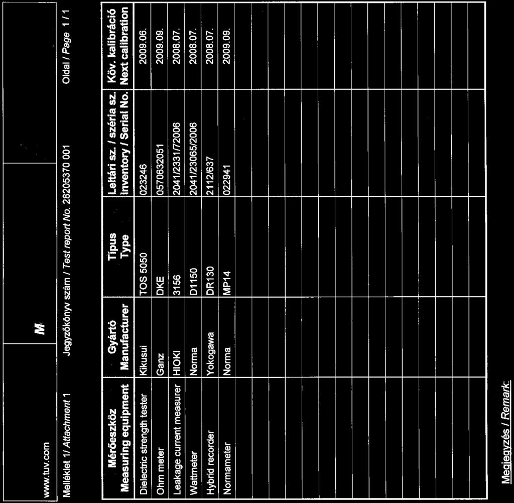
178
TEST REPORT IEC Safety of household and similar electrical appliances Part 2: Particular requirements for massage appliance
 Test Report issued under the responsibility of: SGS- CSTC TEST REORT Safety of household and similar electrical appliances art 2: articular requirements for massage appliance Report Reference No....: GZES100800181503
Tested by (name + signature)... : see on page 1. Approved by (name + signature)... : see on page 1. Tested by (name + signature)...
... : see on page 1. Approved by (name + signature)... : see on page 1. Tested by (name + signature)...") age 2 of 101 Report No. 28225175 001 Testing procedure and testing location: CB Testing Laboratory: Testing location/ address... : TÜV Rheinland InterCert Kft H-1132 Budapest, Váci út 48/A-B., Hungary
age 2 of 101 Report No. 28225175 001 Testing procedure and testing location: CB Testing Laboratory: Testing location/ address... : TÜV Rheinland InterCert Kft H-1132 Budapest, Váci út 48/A-B., Hungary
TEST REPORT IEC Safety of household and similar electrical appliances Part-2-41: Particular requirements for pumps
 Test Report issued under the responsibility of: TEST REORT Safety of household and similar electrical appliances art-2-41: articular requirements for pumps Report Number.... : ITD-14A0233HCS Date of issue...
BS EN : A2:2015 used in conjunction with BS EN : A11:2014 and BS EN 62233:2008
 Test Report Report No 8587907 Client Regal Care Shower Trays Ltd. Regal House, Smithy Lane, Scarisbrick, L40 8HN Authority & date SMO: 8587907, Date: August 9, 2016 Items tested ARESF Body Dryer with alternative
TEST REPORT IEC Safety of household and similar electrical appliances
 Test Report issued under the responsibility of: TEST REORT Safety of household and similar electrical appliances Report Number.... : 160100083SHA-001 Date of issue... : 2016-05-10 Total number of pages...
HISTORICAL OF SAMPLE RECEIVED
 TEST REORT N : LMO-14SE1873DTS HISTORICAL OF SAMLE RECEIVED LCIE CHI RECORDED N DETAIL OF THE SAMLE SECIAL REMARKS -- Original sample None COY OF RATING LATE: Other marking plates are same as above except
TEST REPORT IEC Safety of household and similar electrical appliances Part 2 : Particular requirements for fans Report Reference No.
 Test Report issued under the responsibility of: TEST REORT Safety of household and similar electrical appliances art 2 : articular requirements for fans Report Reference No...: 28210014 001 Date of issue...:
See cover page See cover page
 Test Report issued under the responsibility of: TEST REORT Household and similar electrical appliances Safety art 2-60: articular requirements for whirlpool baths and whirlpool spas Report Number.... :
TEST REPORT ON THE SAFETY OF ELECTRICAL EQUIPMENT FOR PRODUCT INNOVATORS LTD ON A INFRARED TANKLESS HOT WATER SYSTEM
 TEST REPORT ON THE SAFETY OF ELECTRICAL EQUIPMENT FOR PRODUCT INNOVATORS LTD ON A INFRARED TANKLESS HOT WATER SYSTEM MODEL: IR 3000/4000/6000/8000 RH 3500/4500/6500/8500 REPORT NO. TRA-015720-34-00A Test
TEST REPORT IEC Safety of household and similar electrical appliances
 Test Report issued under the responsibility of: TEST REORT Safety of household and similar electrical appliances Report Number....: T211-0590/12 Date of issue...: 2012-11-22 Total number of pages... 93
TEST REPORT IEC Safety of household and similar electrical appliances Part 2: Particular requirements for room heaters
 Test Report issued under the responsibility of: TEST REORT Safety of household and similar electrical appliances art 2: articular requirements for room heaters Report Number.... : 21140671 009 Date of
NCB TÜV SÜD PSB Pte Ltd 1 Science Park Drive, Singapore Singapore
 age 1 of 100 Test Report issued under the responsibility of: NCB TÜV SÜD SB te Ltd 1 Science ark Drive, 118221 Singapore Singapore TEST REORT Safety of household and similar electrical appliances 删除的内容
TEST REPORT EN Household and similar electrical appliances. Safety. General requirements
 TEST REORT EN 60335-1 Household and similar electrical appliances. Safety. General requirements Report Reference No.... : 08.01.16.0258.01 Compiled by (+ signature)... : Approved by (+ signature)... :
TEST REPORT IEC Safety of household and similar electrical appliances
 age 1 of 76 TEST REORT Safety of household and similar electrical appliances Report Number.... : 311280 Date of issue... : 11/11/2016 Total number of pages... : 76 Applicant s name... : Address... : Monotile
TEST REPORT EN Household and similar electrical appliances - Safety Part 1: General requirements
 age 1 of 105 Test Report issued under the responsibility of: AN LAB CO d.o.o. Trgovacka 79 Belgrade 11030 Serbia TEST REORT EN 60335-1 Household and similar electrical appliances - Safety art 1: General
Modified Clauses of EN /A1:2004
 age 2 of 19 Report No.: 17003895 002 7. MARKING AND INSTRUCTIONS Modified Clauses of EN 60335-1/A1:2004 7.1 Symbol IEC 60417-5036, for the enclosure of electrically-operated water valves in external hosesets
TEST REPORT IEC Safety of household and similar electrical appliances
 Test Report issued under the responsibility of: TEST REORT Safety of household and similar electrical appliances Report Number.... : 27113131 001 Date of issue... : 22.10.2013 Total number of pages...
CERTIFICATE OF APPROVAL
 Certificate Number: TUV16069EA CERTIFICATE OF AROVAL.. TUVRheinland Authorised marking: TUV16069EA This is to certify that TOV Rhein/and Australia ty Ltd as accredited by JAS-ANZ in accordance with /SOI/EC
Safety of household and similar electrical appliances
 Test Report issued under the responsibility of: TEST REORT Safety of household and similar electrical appliances Report Number....: GZES171101935301 Date of issue...: 2018-03-16 Total number of pages...:
TEST REPORT IEC/EN Safety of household and similar electrical appliances
 age 1 of 69 TEST REORT Safety of household and similar electrical appliances Report Number.... : Complied by (+ signature)... : Gyewan, Kim Approved by (+ signature)... : Kangsun, Lee Date of issue...
re : CERTIFICATE OF APPROVAL TUV15998EA Certificate Number:
 Certificate Number: TUV15998EA CERTIFICATE OF AROVAL.. TUVRheinland Authorised marking: TUV15998EA This is to certify that TOV Rhein/and Australia ty Ltd as accredited by JAS-ANZ in accordance with /SOI/EC
Test Report issued under the responsibility of: Report Number... : Date of issue... : Total number of pages...
 Test Report issued under the responsibility of: TEST REORT Household and similar electrical appliances - Safety art 2-17: articular requirements for blankets, pads and similar flexible heating appliances
TEST REPORT IEC Safety of household and similar electrical appliances Part 2 : Particular requirements for fans
 Test Report issued under the responsibility of: SGS Fimko Ltd. TEST REORT Safety of household and similar electrical appliances art 2 : articular requirements for fans Report Number.... : GZES151101346201
TEST REPORT IEC Safety of household and similar electrical appliances Part 2: Particular requirements for room heaters
 SHEZHE LCS COMLIACE TESTIG LABORATORY LTD REORT O.: LCS170407067AS Report umber.... : TEST REORT IEC 60335-2-30 Safety of household and similar electrical appliances art 2: articular requirements for room
TEST REPORT IEC/EN Safety of household and similar electrical appliances Part 2: Particular requirements for portable heating tools
 TEST REORT IEC/E 60335-2-45 Safety of household and similar electrical appliances art 2: articular requirements for portable heating tools Report umber....: DE113487 Date of issue...: 2015-06-09 Total
HW C.K. Park. H.S. Choi. KTC(Korea Testing Certification)
") Korea Testing Certification TEST REORT Household and similar electrical appliances - Safety art 2-17: articular requirements for blankets, pads and similar flexible heating appliances Report Reference
Korea Testing Certification TEST REORT Household and similar electrical appliances - Safety art 2-17: articular requirements for blankets, pads and similar flexible heating appliances Report Reference
Report No.: F690501/RF-SAF Testing location:
 age 2 of 81 Summary of testing: The tested samples comply with the requirement of the test specification Tests performed (name of test and test clause): All test Testing location: Copy of marking plate
Test Report issued under the responsibility of: Report Reference No... : Date of issue... : Total number of pages...
 Test Report issued under the responsibility of: TEST REORT IEC/EN 60 335-2-64 Safety of household and similar electrical appliances art 2-64: articular requirements for commercial electric kitchen machines
ZH0505-GR-HT N/A IEC60335_2_9H LCIE
 Test Report issued under the responsibility of TEST REORT Safety of household and similar electrical appliances art 2: articular requirements for grills, toasters and similar cooking appliances Report
INSTITUTE OF TESTING AND CERTIFICATION (INDIA) PVT. LTD. COPY OF MARKING PLATE
 PVT. LTD. COPY OF MARKING PLATE") INSTITUTE OF TESTING AND CERTIFICATION (INDIA) VT. LTD. COY OF MARKING LATE Report No.-ITC/TEST/NN/1508/01 age 3 of 51 (INDIA) VT. LTD. 6 Classification Appliances shall be of one of the following 6.1
INSTITUTE OF TESTING AND CERTIFICATION (INDIA) VT. LTD. COY OF MARKING LATE Report No.-ITC/TEST/NN/1508/01 age 3 of 51 (INDIA) VT. LTD. 6 Classification Appliances shall be of one of the following 6.1
EC Declaration of Conformity According to Low Voltage Directive 2006/95/EC
 EC Declaration of Conformity According to Low Voltage Directive 2006/95/EC Manufacturer's Name: Dae Yeon Co., Ltd. Manufacturer's Address: San 31, Nokchon-ri, hwado-eup, Namyangju-si, Gyeonggi-do, Republic
TEST REPORT IEC Safety of household and similar electrical appliances Part 2 : Particular requirements for fans
 age 1 of 114 Report o.: STUESO017022702211HS TEST REORT Safety of household and similar electrical appliances art 2 : articular requirements for fans Report umber.... : STUESO017022702211HS Date of issue...
KALDEWEI SKIN TOUCH WELLNESSPRODUKT
 KALDEWEI SKIN TOUCH WELLNESSRODUKT GS-Zertifikat für roduktsicherheit. SKIN TOUCH wurde durch den TÜV Rheinland untersucht. Die Untersuchung ergab, dass das SKIN TOUCH System für Badewannen den gestellten
Test Report. Hotpoint Fridge Freezer Model FF175B
 Davy Avenue, Knowlhill Milton Keynes MK5 8NL, United Kingdom Telephone: +44 1908 85 7777 www.intertek.com age 1 of 95 Test Report Hotpoint Fridge Freezer Model FF175B Report No. 103250895MKS-001 Commercial-in-confidence
TEST REPORT EN Safety of household and similar electrical appliances
 age 1 of 54 TEST REORT EN 60335-1 Safety of household and similar electrical appliances Report Reference No.... : Complied by (+ signature)... : Approved by (+ signature)... : TK-CL110016 Byung il, Lee
ZHEJIANG MAXGE ELECTRIC TECHNOLOGY CO., LTD. Address...:
 Test Report issued under the responsibility of: TEST REORT IEC 61008-1 Residual current operated circuit-breakers without integral overcurrent protection for household and similar uses (RCCBs) art 1: General
IECEx TEST REPORT IEC Explosive atmospheres Part 0: Equipment General requirements
 ExTR Reference Number...: ExTR Free Reference Number...: 223531 Compiled by + signature (ExTL)...: Reviewed by + signature (ExTL)...: NO/NEM/ExTR12.0018/00 Stig André Norheim Arne Hortman Date of issue...:
K-SQ13, KA-SQ13, K-SQ14, KA-SQ14, KO-SQ13, KOA-SQ13, KO-SQ14, KOA-SQ14, K-SQ13C, KA-SQ13C, K-SQ14C, KA- SQ14C, KO-SQ13C, KOA-SQ13C, KO-SQ14C,
 age 2 of 14 Model/Type reference...: Ratings...: K-SQ13, KA-SQ13, K-SQ14, KA-SQ14, KO-SQ13, KOA-SQ13, KO-SQ14, KOA-SQ14, K-SQ13C, KA-SQ13C, K-SQ14C, KA- SQ14C, KO-SQ13C, KOA-SQ13C, KO-SQ14C, KOA-SQ14C,
TEST REPORT EN :2012/AC:2014 Household and similar electrical appliances Safety Part 1:General requirements
 age 1 of 54 Ref. o: SCC(15)-40712A-3-10- LVD TEST REORT E 60335-1:2012/AC:2014 Household and similar electrical appliances Safety art 1:General requirements Report Reference o....: SCC(15)-40712A-3-10-
STANDARDS UPDATE NOTICE (SUN) ISSUED: August 23, 2017
 ISSUED: August 23, 2017") STANDARDS UPDATE NOTICE (SUN) ISSUED: August 23, 2017 STANDARD INFORMATION Standard Number: UL 412 Standard Name: Refrigeration Unit Coolers Standard Edition and Issue Date: 5 th Edition Dated August 22,
STANDARDS UPDATE NOTICE (SUN) ISSUED: August 23, 2017 STANDARD INFORMATION Standard Number: UL 412 Standard Name: Refrigeration Unit Coolers Standard Edition and Issue Date: 5 th Edition Dated August 22,
IEC60601_1J. Medical electrical equipment Part 1: General requirements for basic safety and essential performance
 Page 1 of 157 Report No.: E309264-D1009-1-CB CB - IEC REPORT: Test Report issued under the responsibility of: IEC 60601-1 Medical electrical equipment Part 1: General requirements for basic safety and
APPLICATION FOR LOW VOLTAGE DIRECTIVE On Behalf of BestSub Technologies Co Ltd 3D Vacuum Sublimation Machine Model: SZM3D
 ALICATIO FOR LOW VOLTAGE DIRECTIVE On Behalf of BestSub Technologies Co Ltd 3D Vacuum Sublimation Machine Model: SZM3D repared For : BestSub Technologies Co Ltd Rm810 Exchange Square, o.268, Dongfeng Zhong
TEST REPORT IEC , 2 nd Edition Part 1: Equipment classification and requirements
 Test Report issued under the responsibility of: TEST REORT IEC 60825-1, 2 nd Edition art 1: Equipment classification and requirements Report Reference No....: EFSH15041135-IE-01-L01 Date of issue...: May
ENEC NO2187. Nemko hereby grants the following manufacturer as licensee the right to affix this ENEC mark on the product(s) specified below.
 specified below.") ENEC NO2187 age 1/1 Order No. 135699 Licence for use of the here shown ENEC conformity mark : Based on: Agreement on the use of a commonly agreed Mark on Conformity for equipment complying with European
ENEC NO2187 age 1/1 Order No. 135699 Licence for use of the here shown ENEC conformity mark : Based on: Agreement on the use of a commonly agreed Mark on Conformity for equipment complying with European
TEST REPORT IEC Safety of laser products - Part 1: Equipment classification and requirements. TÜV Rheinland Shanghai Co., Ltd.
 Test Report issued under the responsibility of: TEST REORT IEC 60825-1 Safety of laser products - art 1: Equipment classification and requirements Report Number.... : 50089797 001 Date of issue... : 2017.07.25
INTERNATIONAL STANDARD
 INTERNATIONAL STANDARD IEC 60335-2-41 Edition 3.1 2004-03 Edition 3:2002 consolidated with amendment 1:2004 Household and similar electrical appliances Safety Part 2-41: Particular requirements for pumps
APPLICATION FOR LOW VOLTAGE DIRECTIVE On Behalf of. Pest repeller Model: AN-A339
 age 1 of 71 Report o. 201404684S ALICATIO FOR LOW VOLTAGE DIRECTIVE On Behalf of Shenzhen Aosion hotoelectricity Co., Ltd. est repeller Model: A-A339 repared For : Shenzhen Aosion hotoelectricity Co.,
Amendment to Test Report
 - Page 1 of 5 - Test Report issued under the responsibility of: Amendment to Test Report www.nemko.com This Amendment is valid only together with the main Test Report Report o....: 221968 Main Report o...:
TEST REPORT IEC Safety of laser products - Part 1: Equipment classification and requirements
 Test Report issued under the responsibility of: TEST REPORT IEC 60825-1 Safety of laser products - Part 1: Equipment classification and requirements Report Number.... : 102254161MPK-001L Date of issue...
COSφ= V~ 50Hz IP20 Rev.A DehumiDification:1.0 l/h R22: Prated:45W PS: 4.4MPa Ps: 0.6MPa Temp.Class: T1 Weight:19kg
 12011245 001 age 2 of 60 Copy of the marking plate: Refrigerant: R22 ELECTRA MODEL: XD9 RODO.: Fuse: 10A(G) TYE: COSφ=0.95 220-230V~ 50Hz I20 Rev.A DehumiDification:1.0 l/h R22: rated:45w S: 4.4Ma s: 0.6Ma
Page 1 of 90 Report No. J0908CE
 age 1 of 90 Report o. J0908CE8888-0324 TEST REORT IEC/E 60 335-2-40 Household and similar electrical appliances Safety art 2-40: articular requirements for electrical heat pumps,air conditioners and dehumidifiers
TEST REPORT IEC Safety of laser products - Part 1: Equipment classification and requirements
 SHENZHEN LCS COMLIANCE TESTING LABORATORY LTD REORT NO.: LCS1611293204S TEST REORT Safety of laser products - art 1: Equipment classification and requirements Report Number.... : LCS1611293204S Date of
Page 2 of 51. Copy of the marking plate: Refrigerant: R22
 12011921 001 age 2 of 51 Copy of the marking plate: Refrigerant: R22 ELECTRA MODEL:K-36SH ROD O.: Fuse: 25 A(G) TYE: COS =0.95 380-400V~ 50Hz I20 Rev.A Dehumidification: 4.0 l/h R22 rated: 3120 W S: 4.4Ma
Report reference No...: 10TH0052_AS4777_+_ISR_3 Tested by (printed name and signature)...: Urs Seifert. Approved by (printed name and signature)...
...: Urs Seifert. Approved by (printed name and signature)...") TEST REORT AS 4777.2:2005 and AS 4777.3:2005 with additional deviations for Israel Grid connection of energy systems via inverters Grid protection requirements Report reference No...: 10TH0052_AS4777_+_ISR_3
TEST REORT AS 4777.2:2005 and AS 4777.3:2005 with additional deviations for Israel Grid connection of energy systems via inverters Grid protection requirements Report reference No...: 10TH0052_AS4777_+_ISR_3
EN50438 TEST REPORT SUMMARY. Requirements for the connection of micro-generators in parallel with public low-voltage distribution networks
 TEST REORT SUMMARY EN 50438 Requirements for the connection of micro-generators in parallel with public low-voltage distribution networks Report reference number... : 12TH0525-EN50438_SUM_0 Date of issue......:
INTERNATIONAL STANDARD
 INTERNATIONAL STANDARD IEC 60044-7 First edition 1999-12 Instrument transformers Part 7: Electronic voltage transformers This English-language version is derived from the original bilingual publication
Rules for Classification and Construction Additional Rules and Guidelines
 VI Rules for Classification and Construction Additional Rules and Guidelines 7 Guidelines for the Performance of Type Approvals 7 Test Requirements for Statical Converters with Semi-Conductors Edition
Test report. ifesesws^ Date: Number: T /17 Project file: C Pages: Product: Fixed general purpose LED luminaire
 Sl/Q ifesesws^ SLOVENSKA AKREDITACIJA SIST EN ISO/ 1EC 17025 L-009 Test report Number: roduct: roject file: Fixed general purpose LED luminaire Date: ages: C20170767 2017-04-26 12 Type reference: LA-FL/G-xxW-xxxxK-Rxxx/xxx-(D10kGy)
AS/NZS IEC :2013
 AS/NZS IEC 61347.2.13:2013 (IEC 61347-2-13, Ed.1.0 2006, MOD) Australian/New Zealand Standard Lamp controlgear Part 2.13: Particular requirements for d.c. or a.c. supplied electronic controlgear for LED
INTERNATIONAL STANDARD
 INTERNATIONAL STANDARD IEC 60335-2-6 Fifth edition 2002-07 Household and similar electrical appliances Safety Part 2-6: Particular requirement for cooking ranges, hobs, ovens and similar appliances Appareils
An Urgent Bulletin from CSA Group
 Ref No: I16-140 Appliances No. 48 (Supersedes Informs Appliances No. 21, Ref No: I12-107) Date: December 21, 2016 An Urgent Bulletin from CSA Group Existing Certification not affected Apply any time to
AS/NZS :2003 Luminaires - Part 1: General requirements and tests
 Menu Home About this portal Latest updates Print Save Email Resource detail Citations AS/NZS 60598.1:2003 Luminaires - Part 1: General requirements and tests Table of Contents View on Information Provider
Consumer Products Services Germany GmbH Türkheim Germany
 TEST REORT SUMMARY EN 50438 Requirements for the connection of micro-generators in parallel with public low-voltage distribution networks Report reference number... : 11TH0290-EN50438_SUM_2 Date of issue......:
IEC60601_1K. Medical electrical equipment Part 1: General requirements for basic safety and essential performance
 Page 1 of 165 Report No.: E309264-D1028-1/A0/C0-UL Test Report issued under the responsibility of: IEC 60601-1 Medical electrical equipment Part 1: General requirements for basic safety and essential performance
FINAL ATEX REPORT ON EQUIPMENT FOR USE IN POTENTIALLY EXPLOSIVE ATMOSPHERES FOR GOLDEN PROMISE EQUIPMENT INC. FLOW MONITOR, GPE3000 SERIES,
 FINAL ATEX REPORT ON EQUIPMENT FOR USE IN POTENTIALLY EXPLOSIVE ATMOSPHERES FOR GOLDEN PROMISE EQUIPMENT INC. ON FLOW MONITOR, GPE3000 SERIES, REPORT NO. TRA-015825-33-00A ExTR Reference No. TRA-015825-33-00A
Operating instructions Safety-monitoring module SRB 302X3. 1. About this document. Content
 8 Appendix 8.1 Wiring examples...4 8.2 Start configuration...4 8.3 Sensor configuration...4 8.4 Actuator configuration...5 Operating instructions.............pages 1 to 6 Original 9 EU Declaration of conformity
This is a preview - click here to buy the full publication ICS ISBN
 CONSOLIDATED VERSION IEC 60691 Edition 4.1 2019-01 colour inside Thermal-links Requirements and application guide INTERNATIONAL ELECTROTECHNICAL COMMISSION ICS 29.120.50 ISBN 978-2-8322-6430-0 Warning!
Test Report issued under the responsibility of:
 Test Report issued under the responsibility of: NCB TÜ V SÜ D PSB Pte Ltd 1 Science Park Drive, Singapore 118221 TEST REPORT IEC 61347-2-13 Part 2: Particular requirements: Section Thirteen d.c. or a.c.
Operating instructions Safety-monitoring module SRB 302X3. 1 About this document
 1 About this document Operating instructions... pages 1 to 6 Translation of the original operating instructions 1.1 Function This operating instructions manual provides all the information you need for
INTERNATIONAL STANDARD NORME INTERNATIONALE
 IEC 62031 INTERNATIONAL STANDARD NORME INTERNATIONALE Edition 1.0 2008-01 2 62031 IEC:2008 CONTENTS FOREWORD...3 INTRODUCTION...5 1 Scope...6 2 Normative references...6 3 Terms and definitions...7 4 General
Table of Contents FOREWORD... 3 INTRODUCTION SCOPE NORMATIVE REFERENCES DEFINITIONS AND ABBREVIATIONS REQUIREMENTS...
 TITLE SPECIFICATION FOR PHOTOELECTRIC CONTROL UNITS (PECUs) REFERENCE REV DATE: JUNE 2017 PAGE: 1 OF 16 REVISION DATE: Table of Contents FOREWORD... 3 INTRODUCTION... 4 1 SCOPE... 4 2 NORMATIVE REFERENCES...
TEST REPORT EN :2002+A1:2004+A11:2004+A2:2006+A12:2006 EN : 2003+A1:2008
 TEST REORT E 60335-1:2002+A1:2004+A11:2004+A2:2006+A12:2006 E 60335-2-23: 2003+A1:2008 Safety of household and similar electrical appliances art 2-23: articular requirements for appliances for skin or
INTERNATIONAL STANDARD
 INTERNATIONAL STANDARD IEC 60335-2-55 Third edition 2002-11 Household and similar electrical appliances Safety Part 2-55: Particular requirements for electrical appliances for use with aquariums and garden
INTERNATIONAL STANDARD
 INTERNATIONAL STANDARD IEC 62052-11 First edition 2003-02 Electricity metering equipment (AC) General requirements, tests and test conditions Part 11: Metering equipment This English-language version is
INTERNATIONAL STANDARD
 INTERNATIONAL STANDARD IEC 60335-2-3 Edition 5.1 2005-01 Edition 5:2002 consolidated with amendment 1:2004 Household and similar electrical appliances Safety Part 2-3: Particular requirements for electric
IEC60601_1J. Medical electrical equipment Part 1: General requirements for basic safety and essential performance
 Page 1 of 170 Report No.: E309264-D1021-1/A1/C0-UL IEC REPORT: Test Report issued under the responsibility of: IEC 60601-1 Medical electrical equipment Part 1: General requirements for basic safety and
INTERNATIONAL STANDARD
 INTERNATIONAL STANDARD IEC 60335-2-30 Edition 5.0 2009-11 Household and similar electrical appliances Safety Part 2-30: Particular requirements for room heaters INTERNATIONAL ELECTROTECHNICAL COMMISSION
TEST REPORT IEC MEDICAL ELECTRICAL EQUIPMENT
 Test Report issued under the responsibility of: TEST REORT MEDICAL ELECTRICAL EQUIMENT art 1-11: General requirements for basic safety and essential performance Collateral Standard: Requirements for medical
INTERNATIONAL STANDARD
 INTERNATIONAL STANDARD IEC 61810-1 Second edition 2003-08 Electromechanical elementary relays Part 1: General and safety requirements Relais électromécaniques élémentaires Partie 1: Exigences générales
INTERNATIONAL STANDARD
 INTERNATIONAL STANDARD IEC 60335-2-23 Fifth edition 2003-01 Household and similar electrical appliances Safety Part 2-23: Particular requirements for skin or hair care Sécurité des appareils électrodomestiques
INTERNATIONAL STANDARD
 INTERNATIONAL STANDARD IEC 60335-2-15 Fifth edition 2002-07 Household and similar electrical appliances Safety Part 2-15: Particular requirements for appliances for heating liquids Appareils électrodomestiques
TC 61. Technical Committee 61 SAFETY OF HOUSEHOLD AND SIMILAR ELECTRICAL APPLIANCES
 Technical Committee 61 SAFETY OF HOUSEHOLD AND SIMILAR ELECTRICAL APPLIANCES Ensuring performance and safety of household electrical appliances in industrializing countries Seattle, Washington, USA: 2010-13-10
INTERNATIONAL STANDARD
 INTERNATIONAL STANDARD IEC 60335-2-11 Sixth edition 2002-03 Household and similar electrical appliances Safety Part 2-11: Particular requirements for tumble dryers Appareils électrodomestiques et analogues
INTERNATIONAL STANDARD
 INTERNATIONAL STANDARD IEC 60335-2-13 Edition 6.0 2009-12 Household and similar electrical appliances Safety Part 2-13: Particular requirements for deep fat fryers, frying pans and similar appliances INTERNATIONAL
Test procedure/ method name. method identification. Testing of industrial and explosion isolation valves and tank lining
 The Laboratory is qualified to update standards identifying the test procedures. The laboratory requires/applies a flexible scope of accreditation permitted as detailed in the Annex. Updated list of activities
INTERNATIONAL STANDARD
 INTERNATIONAL STANDARD IEC 60335-2-24 Sixth edition 2002-10 Household and similar electrical appliances Safety Part 2-24: Particular requirements for refrigerating appliances, ice-cream appliances and
INTERNATIONAL STANDARD
 INTERNATIONAL STANDARD IEC 60335-2-11 Edition 6.1 2003-02 Edition 6:2002 consolidated with amendment 1:2003 Household and similar electrical appliances Safety Part 2-11: Particular requirements for tumble
INTERNATIONAL STANDARD
 INTERNATIONAL STANDARD IEC 60335-2-17 Second edition 2002-10 Household and similar electrical appliances Safety Part 2-17: Particular requirements for blankets, pads and similar flexible heating appliances
Page 2 of 14 Report Ref. No
 age 2 of 14 Summary of testing: Tests performed (name of test and test clause): Clause 6.1, Initial measurements: - MST 01: Visual inspection - 10.2: Maximum power determination - MST 16: Dielectric withstand
Cat. N. Cat. N (s) 1. DESCRIPTION - USE 3. OVERALL DIMENSIONS. Technology : 4. PREPARATION - CONNECTION 2. PRODUCT RANGE
 1. DESCRIPTION - USE 3. OVERALL DIMENSIONS. Technology : 4. PREPARATION - CONNECTION 2. PRODUCT RANGE") Cat. N STOP & GO automatic resetting 87045 LIMOGES Cedex - FRANCE Telephone : + 33 5 55 06 87 87 Fax: + 33 5 55 06 88 88 Cat. N (s) : 4 062 88 / 4 062 89 CONTENTS PAGE 1. Description - Use... 1 2. Product
Cat. N STOP & GO automatic resetting 87045 LIMOGES Cedex - FRANCE Telephone : + 33 5 55 06 87 87 Fax: + 33 5 55 06 88 88 Cat. N (s) : 4 062 88 / 4 062 89 CONTENTS PAGE 1. Description - Use... 1 2. Product
Model No.: VS806-6N ( ) V~ 50/60Hz LED 6x4W
 V~ 50/60Hz LED 6x4W") Reference o.:wtf13f1210249r1s age 2 of 10 Test item description... : Trade Mark... : --- Model/Type reference... : Ratings... : Copy of marking plate: Ceiling Lamp VS806-6(180.003590); VS806-6(180.003591),
Reference o.:wtf13f1210249r1s age 2 of 10 Test item description... : Trade Mark... : --- Model/Type reference... : Ratings... : Copy of marking plate: Ceiling Lamp VS806-6(180.003590); VS806-6(180.003591),
This is a preview - click here to buy the full publication. High-voltage switchgear and controlgear
 IEC/PAS 62271-109 Edition 1.0 2002-07 High-voltage switchgear and controlgear Part 109: Alternating-current series capacitor by-pass switches PUBLICLY AVAILABLE SPECIFICATION INTERNATIONAL ELECTROTECHNICAL
KINGDOM OF SAUDI ARABIA SASO/IEC /2012 SASO IEC
 SASO IEC 60335-2-6 HOUSEHOLD AND SIMILAR ELECTRICAL APPLIANCES- SAFETY PART 2-6: PARTICULAR REQUIREMENTS FOR STATIONARY COOKING RANGES, HOPS, OVENS AND SIMILAR APPLIANCES Date of SASO Board of Directors
INTERNATIONAL STANDARD
 INTERNATIONAL STANDARD IEC 60335-2-70 Second edition 2002-03 Household and similar electrical appliances Safety Part 2-70: Particular requirements for milking machines Appareils électrodomestiques et analogues
INTERNATIONAL STANDARD
 INTERNATIONAL STANDARD IEC 60335-2-60 Third edition 2002-11 Household and similar electrical appliances Safety Part 2-60: Particular requirements for whirlpool baths Appareils électrodomestiques et analogues
INTERNATIONAL STANDARD
 INTERNATIONAL STANDARD IEC 62052-21 First edition 2004-05 Electricity metering equipment (a.c.) General requirements, tests and test conditions Part 21: Tariff and load control equipment IEC 2004 Copyright
HMN-D2 Insert Series
 HMN-D2 Insert Series Table of contents 1. SCOPE... 2 1.1. Content... 2 1.2. Qualification... 2 2. APPLICABLE DOCUMENTS... 2 2.1. TE Connectivity Documents... 2 2.2. Other Documents... 2 3. REQUIREMENTS...
INTERNATIONAL STANDARD
 INTERNATIONAL STANDARD IEC 60335-2-74 Second edition 2002-10 Household and similar electrical appliances Safety Part 2-74: Particular requirements for portable immersion heaters Appareils électrodomestiques
INTERNATIONAL STANDARD
 INTERNATIONAL STANDARD IEC 60335-2-65 Second edition 2002-10 Household and similar electrical appliances Safety Part 2-65: Particular requirements for air-cleaning appliances Appareils électrodomestiques
INTERNATIONAL STANDARD
 INTERNATIONAL STANDARD IEC 60335-2-6 Fifth edition 2002-07 Household and similar electrical appliances Safety Part 2-6: Particular requirements for stationary cooking ranges, hobs, ovens and similar appliances