University of Miami Interdisciplinary Laboratory. Benjamin J. Burgoyne Mechanical Option Spring 2007 Faculty Consultant: Jim Freihaut
|
|
|
- Curtis Kelley
- 5 years ago
- Views:
Transcription


1 University of Miami Benjamin J. Burgoyne Spring 2007 Faculty Consultant: Jim Freihaut


2
3 Table of Contents Executive Summary... page 3 Introduction page 4 Building. page 5 Mechanical System page 7 -Office System... page 7 -Laboratory System page 7 -Penthouse System. page 8 -FCU System.. page 8 System Enhancement- Depth. page 9 -CAV-VAV.. page 9 -Spray Desiccant page 12 -Comparison.. page 16 System Enhancements- Breadths... page 17 -Structure... page 18 -Electrical System.. page 21 Economic Analysis page 24 Conclusion. page 25 Acknowledgements page 26 Figures -Figure 1. page 5 -Figure 2. page 11 -Figure 3. page 13 -Figure 4. page 17 -Figure 5. page 19 -Figure 6. page 19 -Figure 7. page 19 -Figure 8. page 20 Ben Burgoyne University of Miami
4 -Figure 9. page 20 -Figure page 22 -Figure page 22 Schematics -S.5. page A-1 -S.6. page A-2 -S.7. page A-3 -S.8. page A-4 -S.9. page A-5 Tables -Table 1.. page B-1 -Table 2.. page B-2 -Table 3.. page 10 -Table 4.. page B-5 -Table 5.. page 14 -Table 6.. page B-6 -Table 7.. page 16 -Table 8.. page B-7 -Table 9.. page B-8 -Table 10 page 19 -Table 11 page B-9 -Table 12 page 22 -Table 13 page 23 -Table 14 page 24 Calculations -Calculation 1... page C-1 -Calculation 2... page C-4 Ben Burgoyne University of Miami
5 Executive Summary: This report presents the current mechanical design of the University of Miami Interdisciplinary laboratory, then suggests and implements, via calculation, additions and alterations meant to make it more energy efficient. The building is 10 floors high and is 178,000 square feet. Separate mechanical systems serve the laboratory and vivarium section, the office section, the penthouse mechanical floor, and general technical and equipment rooms. The Laboratory System is the focus of enhancements because it is the largest system, and because of the large potential for improvement for the current air distribution and dehumidification processes. The Laboratory System is controlled air volume (CAV). The change introduced is making it variable air volume (VAV). This is carried out by replacing the constant volume terminal units with variable volume terminal units. The maximum air flow is set at the existing CAV levels, and the minimum flow is set at minimum ventilation requirements according to ASHRAE Standard Energy consumption analysis is carried out through simulation. A Percent Load Profile is thereby derived and combined with the peak load, which is the calculated cooling load. The annual energy savings is 14,062 MMBtu, and the associated economic savings is $16,700 per year. The payback period is 4-5 years. The existing system dehumidification uses cooling coils to dehumidify. The proposed change is to use a spray desiccant. Kathabar Systems produces equipment to spray a water/lithium chloride solution into the supply air stream, removing the moisture. Cooled solution cools the supply air as well. Peak cooling loads from this process are also combined with the Percent Load Profile, with both the CAV and VAV profiles. CAV Kathabar savings are 27,949 MMBtu and $33,300 per year with a year payback. VAV Kathabar savings are 33,284 MMBtu and $39,600 per year with a 6-9 year payback. The big difference in payback between CAV Kathabar and VAV Kathabar occurs because the spray desiccant system makes terminal reheat unnecessary. Savings on that material are significant enough to cause that difference. Structural and electrical studies are also carried out to ensure that the new Kathabar equipment will be adequately supported and receive the necessary power. New precast concrete joists are sized at12rb28, but the other structural elements are sufficient, and new circuits are run off an existing panel board. Despite the longer payback, significant energy savings with the VAV/spray desiccant dehumidification enhancements cause that system to be the recommended alternative. Ben Burgoyne University of Miami

6 Introduction The focus of this study is the University of Miami, an office and research laboratory building currently being constructed on the campus of the University of Miami in Florida. Hereafter, the building shall be referred to as the UMIL. The UMIL s being located in a hot, humid climate, and its use requiring strict air conditions, make the effectiveness of the mechanical system an item of interest. Can it supply the necessary conditioning with minimal energy consumption? In this study, the design of the UMIL is analyzed with a focus on the mechanical system. Reviews of the current design strategies, equipment efficiencies, and energy consumption, as well as envelope, electrical system, and location demographic, can all reveal measures that may be taken to improve the system. This report presents the current mechanical design of the UMIL, then suggests and implements, via calculation, additions and alterations meant to improve it. The improvement shall be measured by total energy consumption with accompanying economic impacts. The results will show whether the system changes are worth implementing. courtesy of Google Maps Ben Burgoyne University of Miami


7 Building The UMIL is a research facility, designed for the keeping and studying of animals. It comprises approximately 10 floors and is 178,000 square feet. The first two floors contain animal vivaria, along with spaces to treat the animals, maintain and clean their confinement equipment, and store their food. Floors three through nine are typical, and they include two large general laboratories, with fume hoods, and several smaller research spaces. On all the floors, the listed science-focused spaces are located on the east side of the building. The west side contains office space. The technical spaces are located on the tenth floor, which is a mechanical penthouse, and on the first floor. The first floor footprint is significantly larger than the upper floors, which retain relatively the same perimeter dimensions. A large extension off the north side of the building is the focus of the first floor technical rooms, including general electrical and telecommunications rooms, a boiler room, and a generator room. Figure 1 shows the locations of the general space systems. 1 st Floor Plan 2 nd Floor Plan 3 rd -9th Floor Plans Penthouse Plan Office System FCU Systems Laboratory System Penthouse System Figure 1 UMIL Systems Ben Burgoyne University of Miami


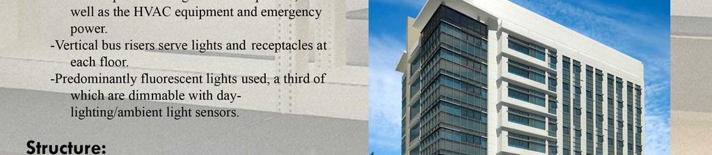
8 The typical architectural style of the University of Miami campus includes a white, concrete façade, blue-green fenestration, and palm tree dotted landscaping. The UMIL uses the same coloring and architectural elements, thus fitting in with the surrounding structures. This style also includes a large percentage window area. Mechanically speaking, too much window area is unfavorable in the hot Miami climate. Excessive solar heat gain adds to the already high cooling load. The UMIL avoids this issue with the use of aluminum spandrels colored the same as the glass, thereby creating an illusion of windows without the solar gain. The thermal resistance of the spandrel is indeed lower than the remaining façade s concrete panel assembly. However, the spandrel, in terms of energy efficiency, is still more favorable than glass. Less window area is acceptable even from an interior-aesthetic perspective, because the presence of windows in many of the spaces is either inappropriate or unnecessary. Those spaces include cage wash rooms, mechanical spaces, and animal holding rooms. The animal rooms, for instance, may require strict lighting and thermal conditions that can be adversely affected by a window. In other spaces where windows are present, the extra light is used to soften the burden of electrical consumption. Automatic day lighting controls are used with the perimeter lamps, turning them off when ambient light is sufficient. In addition, perimeter ceilings are angled in such a way as to reflect the outside light more effectively to work spaces. A building-wide 1250 kw capacity electrical system supplies the fluorescent lights as well as all receptacles, equipment, and emergency power. In addition to its use for the façade, concrete is the primary element in the UMIL structural system. Each floor is a cast-in-place concrete slab, with the first floor being slab on grade. The upper slabs are supported by a one-way system consisting of specially made 16 inch precast concrete joists. These are mostly spaced 5 6 apart and the longest span is 33. Supporting the joists are concrete beams and columns. The exception to the concrete norm is the roof assembly, which is held up by steel members. The mechanical system shall be discussed in detail in the Mechanical System section. Ben Burgoyne University of Miami
9 Mechanical System Cooling at the UMIL is supplied by a 20,000 ton campus chiller plant, and the heating by two 10,043 MBH steam boilers located in the first floor boiler room. The chilled water is supplied to UMIL at about 3,300 gpm and 44 F. It is returned at 56 F. The boilers create 80 psig steam that is used by glass and cage washing equipment and to create about 500 gpm of 180 F hot water via a heat exchanger. That hot water returns to the heat exchanger at 150 F. These plants supply four mechanical systems in the UMIL: the Office System serving the office spaces located on the first through ninth floors; the Laboratory System serving the laboratory and vivarium spaces on the first through ninth floors; the Penthouse System serving the penthouse mechanical floor; and the FCU system serving the first floor mechanical and other technical spaces. The following is a detailed description of each system. -Office System One 48,500 cfm air handling unit serves 50,000 square feet of office space. It is a return air system, drawing air from the spaces via ceiling plenums to mix with outside air. The supply air is cooled and dehumidified with chilled water coils, then reheated by hot water, variable volume terminal units. Dedicated exhaust systems serve the restrooms, kitchen areas, and janitor closets. The air schematic of the system is shown in Schematic S-8 and Schematic S-9. -Laboratory System Four 51,000 cfm air handling units supply 108,000 square feet of laboratory and vivarium space. Like the Office System, supply air is cooled and dehumidified by cooling coils, then reheated by hot water terminal units. However, the Laboratory System differs in that it supplies 100% outside air and the terminal units supply it at constant volume, adjusting the hot water flow through the coils to control the supply air temperature. All the space air is exhausted outside of the building. There is a series of laboratory exhaust configurations for the system air. Nine risers with accompanying fans serve exclusively seven radioisotope and two necropsy rooms within the system. There is one radioisotope room located on each of the third through ninth floors. The necropsy rooms are found on the first and second floor. Additionally, there are dedicated exhaust systems for the cage wash areas and vivarium spaces on the first and second floors. The remaining laboratory spaces are served by fume hoods and a general exhaust system. The fume hoods are activated by Phoenix controls whenever the hoods are manually opened. They exhaust at constant volume. An energy saving technique is used with the general exhaust system. It is powered by four 35,000 cfm energy recovery units, with a heat recovery runaround coil connecting these units with the Laboratory System air handling units. In the summer, this coil captures sensible heat in the hot, entering air stream and releases it into the cool, exhaust air stream. At design conditions, the runaround coil lowers entering air 10 F. Ben Burgoyne University of Miami
10 Entering that temperature difference, along with air handling unit maximum air flow rate of 204,000 cfm, into the sensible heat equation, Qsensible = q dt where Qsensible is sensible heat (Btu/hr), q is air volume flow (cfm), and dt is temperature difference ( F), gives Qsensible = ,000cfm 10F Qsensible = 2,203,200Btu / hr or Qsensible = 183.6tons in energy saved. Even taking into account the energy required to pump the heat recovery water through the runaround coil, this can amount to significant savings. In another section, actual system flow rates will be used in energy calculation. The air schematics for this system are found in Schematic S-5, Schematic S-6, and Schematic S-7. -Penthouse System Two 4,000 cfm air handling units serve the12,000 square foot, tenth floor mechanical penthouse. This is a simple system, using only cooling coils and drawing in 100% return air. Because it is a non-occupied space, there are no outside air or exhaust requirements. -FCU System Three 1,200 cfm fan coil units (FCU s) serve the first floor technical spaces, which amount to 8,000 square feet. These are cooling coil only, and, like the Penthouse system, outside air and exhaust are non-issues. Ben Burgoyne University of Miami
11 System Enhancement-Depth It is my supposition that a significant portion of the total building energy consumption can be saved with two changes to the Laboratory System. First, the controlled air volume (CAV) system should be changed to variable air volume (VAV). Second, a spray desiccant should be used instead of cooling coils to perform dehumidification. It is generally accepted that CAV and cooling coil dehumidification tend to be simpler to design than other air distribution and dehumidification alternatives, and that they carry lower first costs. Assuming these are correct statements, the alternatives need to not just save energy, but save enough energy, and thus money, to make up for the difference within a reasonable amount of time. This information can be determined by assessing the existing system energy consumption, followed by the energy consumed by the new system. Affixing a cost to the energy and comparing to the added first cost of the new system will reveal the time it takes to save an amount equal to the amount spent. The following sections will describe the two changes in detail, and calculate the energy consumption. -CAV-VAV There was no energy-related motivation to use a CAV system with the laboratory spaces. According to the design engineers, the decision to go with CAV came directly from the owner, who did not want a more complicated VAV system to be faultily designed or maintained. This is understandable; consistently maintaining design conditions is too important, especially in a laboratory setting. Evidently, bad prior experience with VAV had left the owner disinclined to try it again. In this situation, making the design equipment change to VAV is not difficult. The air handling units and exhaust fans are already equipped to handle variable volume flow. Their fans run on variable frequency drives. Likewise, the air handling unit cooling coil control valves can modulate to control flow. The system maintains constant volume with the terminal units. Based on the preset supply duct air pressure, they are adjusted to allow only the preset air flow rate through. Those set flow rates, per terminal unit, are shown in Table 1. In order to change the system to variable volume, the terminal units need to be exchanged with variable volume counterparts. Aside from the return air, this new system is extremely similar to the Office System, and those same terminal units can be used. With the new terminal units, ranges of air flow rates, instead of single flow rates, need to be determined. It is assumed that the existing system can adequately meet design conditions. Therefore, the fans and coils shall not be upsized. Also, the maximum set point for the new variable volume terminal units will equal the CAV set points. The fluctuation will occur when the system is at less than peak load. Only minimum flow rates, then, need to be determined. The lowest load a space can possibly have is zero. However, the building code requires a minimum supply of outside air. Therefore, a satisfactory minimum setpoint for the terminal units would be the standard ventilation requirement for the spaces they supply. The required rates are calculated based on ASHRAE Standard The calculation of the Laboratory System room Ben Burgoyne University of Miami
12 ventilation rates is found in Table 2a, Table 2b, and Table 2c. When those flow rates are applied to the rooms terminal units, the minimum terminal unit flow rates are achieved. These are shown in Table 1. Based on the maximum and minimum flow rates, the associated system range is obtained. According to Table 1, the maximum is 171,710 cfm, and the minimum is 26,919 cfm. This is the extent for the system, but a building simulation needs to be carried out in order to determine how much time the system spends at different points within the that range. That information, comprising an energy load profile, can be applied over a year, and will show the energy consumption. Trace 700, a product of Trane, is the mechanical simulation program that is used in this study. With Trace 700, an accurate model can be created with the exception of one factor. The program does not allow for 100% outdoor air, it will only simulate a return air system. For this reason, an accurate final energy consumption total is not given. However, some products of the simulation are assumed to be independent of percent outdoor air. One such product is the System Load Summary. The data in this report divides the peak load into five percentile increments. It then lists the percent of the time (per year) that the system was at each load percentile. For example, one could use the report to look up how many hours in the year the system was at 50% load. We will call the percentage part of the System Load Summary the Percent Load Profile. Table 3 shows the Percent Load Profile for the Laboratory System Trace 700 simulation. In order to approach the real system, the assumption is made that, with all else equal, the Percent Load Profile for a 100% outdoor air system is the same as for a return air system, even though the peak loads are different. Subsequent energy calculations will be based on this assumption. Table 3 Percent Load Profile Laboratory System Ben Burgoyne University of Miami

13 Figure 2 CAV/VAV Design Conditions Psychrometric Chart In order apply the Percent Load Profile, the true Laboratory system peak load needs to be determined. Here, another simulation product is used: peak supply air flow rate. For the same building and conditions, the same amount of supply air must be maintained to meet the load, regardless of whether it was partially returned or not. At the outlet stage, in both cases, the air conditions are the same. Therefore it is assumed that the peak supply air flow rate for a return air system is the same as that for a 100% outdoor air system. According to the simulation, the peak flow rate is 100,000 cfm, and it is used in the sensible and latent heat equations to determine the peak cooling load. The latent heat equation used is Qlatent = q dw where Qlatent is sensible heat (Btu/hr), q is air volume flow (cfm), and dw is difference in humidity ratio (grains moisture/pounds dry air). Using the psychrometric chart, shown in Figure 2, initial conditions are determined as 81 F and 120 grains/lbmda. This condition is a cooling degree day, as given by project specifications, minus 10 F (taken care of by the runaround coil). The final condition, also taken from specifications, is 50 F and 50 grains/lbmda. This is the air leaving the cooling coil. Taking the temperature and humidity differences, and inserting them into the equations gives: Ben Burgoyne University of Miami
14 Sensible Qsensible = 1.08 q dt Qsensible = ,000cfm 31F Qsensible = 3,348,000Btu / hr or Qsensible = 279tons Latent Total Qlatent = 0.68 q dw Qlatent = ,000cfm 66gr / lbmda Qlatent = 4,488,000Btu / hr or Qlatent = 374tons Qtotal = Qsensible + Qlatent Qtotal = 3,348,000Btu / hr + 4,488,000Btu / hr Qtotal = 7,836,000Btu / hr or Qtotal = 653tons As shown, the total cooling load is calculated simply by adding the sensible and latent loads. Now that the peak cooling load is determined, it is inserted into the Percent Load Profile to discover the total yearly energy consumption for each system. This is shown in Table 4, and the resulting consumptions are 45,034 MMBtu and 30,973 MMBtu for the CAV and VAV systems respectively. As expected, the VAV system consumption is less than the CAV system. In the Economic Analysis section, the difference in resulting cost with be analyzed in detail, and a final judgment regarding system decision can be made. In preparation for that section, it is noted that this assessment only compares energy in terms of actual cooling, not in heating, reheat, fan energy, or other total energy considerations. It is the purpose of this study to determine if the savings on cooling alone would warrant a system change. -Spray Desiccant As stated in the Introduction, designing an effective mechanical system can be difficult in a hot, humid climate, especially with a demand for 100% outside air. Using a cooling coil for dehumidification requires the incoming air to be cooled below the desired supply set point, then to be reheated. An alternative that doesn t require air to go through the extra cooling and reheating (which is, of course, energy consuming) is worth investigating. Ben Burgoyne University of Miami
15 Based on building use, a spray desiccant is the most appropriate alternative to cooling coil dehumidification for the UMIL. With other buildings, an enthalpy wheel would be considered; with one circular motion, the solid desiccant material would absorb heat and moisture from the incoming air stream and deposit it into the outgoing air stream. This process is known to greatly increase the efficiency of a system, and high first cost is the greatest limitation to its use. However, the unfavorable exhaust air quality of the Laboratory System discourages use of the enthalpy wheel. System air can become saturated with dangerous chemicals, biological products, and other contaminants, which necessitates 100% outside air to replace it. An enthalpy wheel exposed to such exhaust can possibly pick up that contamination and return it to the incoming stream, and is thus excluded from consideration. A spray desiccant system would preserve incoming air quality while still creating energy savings. Such a system is offered by Kathabar Systems. With Kathabar, a liquid desiccant solution is sprayed into the supply air stream to dehumidify as well as cool it. Figure 3 illustrates the process that the desiccant solution undergoes. The substance is a water/lithium chloride salt solution, called Kathene, which is ton-toxic. Within the conditioner unit, located in the supply air stream, the Kathene is cooled by chilled water in a heat exchanger, and is sprayed into the supply air stream. The solution cools the air Figure 3 Kathabar System Schematic Ben Burgoyne University of Miami

16 and naturally absorbs the water vapor. It then falls from the air, and is gathered at the bottom of the unit. At this stage, the solution is lithium chloride lean (excess water). A portion is therefore pumped to the regenerator unit, located on the exterior of the building. It is heated with the hot water heat exchanger and sprayed into a forced outdoor air current. Because it is heated, the solution wants to get rid of the moisture it contains, which is taken away via evaporation. The remaining lithium chloride rich solution is gathered at the bottom of the unit and pumped back to the conditioner. In this way, the solution concentration is controlled. That concentration determines the amount of moisture removed from the air stream, and is variable, so it can adjust automatically to meet any sensible or latent load. Supply air quality is preserved because the regenerator can be placed anywhere, well away from the exhaust. Additionally, an eliminator system in the conditioner unit serves as a filter, trapping particulates. The lithium chloride carryover into the building equates to about 2 ppb when the system is adequately maintained. It is necessary here to note that Kathabar Systems are usually applied to small spaces or special design conditions, such as industrial or refrigeration uses, where extremely cold, dry air is required. Nevertheless, the Kathabar system is analyzed for the UMIL to see if, despite the unorthodox application to a large laboratory building, sufficient energy is saved to warrant the change. The actual application to a building system, including equipment sizing and peak load determining, is shown in Kathabar literature, namely Kathabar Systems Application Manual for Kathapac Dehumidification. These calculations run for the Laboratory System are found in Calculation 1. In addition to the information shown there, special charts are used to obtain some of the given values. These charts are found in the manual, but because of copyright and space purposes, they are not reprinted here. Table 5 summarizes the data required to run the calculation and the ultimate information derived. One key aspect is the determination of required chilled water temperature. This depends on the difference between the air conditions entering the conditioner unit and leaving it. The existing chilled water temperature for the UMIL is 44 F. Using air coming directly from the runaround coils, assumed at 81 F maximum, the chilled water temperature required by the Kathabar calculation is less than 44 F. This deficiency can be remedied in one of two ways. A small chiller can be designed and installed to lower the Table 5 Calculation Input/Outcome Kathabar System Ben Burgoyne University of Miami
17 campus chilled water temperature to the required level, or the supply air can be cooled further before it reaches the conditioner unit. The second option is taken in this study, because the cooling coils are already in place within the existing air handling unit assemblies. It is assumed that making use of those coils would be much simpler and more cost efficient than a whole new chiller or chillers. Working backwards in the calculations from the desired 44 F CHW, it is determined that the necessary conditioner entering air conditions are 72 F and 115 gr/lb. At design conditions, with dt = 81F 72F and q = 100,000cfm the extra required cooling becomes dt = 81F 72F q = 100,000cfm Qsensible = ,000 9 Qsensible = 972,000Btu / hr or Qsensible = 81tons This extra cooling is taken into account, in addition to the given Kathabar System values. Added together, they become the peak cooling load, and can therefore be input into the Percent Load Profile to obtain the energy usage. The yearly cooling energy consumptions are show in Table 6. The same Percent Load Profiles for CAV and VAV are used as before because the same expected flow rates are assumed to pass through the Kathabar system. The Kathabar system energy consumptions are 17,086 MMBtu for CAV application and 11,571 MMBtu for VAV. Again, the CAV requires more energy than the VAV Kathabar configuration. The Kathabar System creates a significant change in the air distribution system. The air temperature leaving the conditioner unit is 55 F. The terminal units receiving this air are specified to receive 50 F air, heat it, and distribute it at 55 F. This was the reheat stage of the cooling coil dehumidification. With the supply air already at the design temperature, the reheat becomes unnecessary. Also, the original CAV system modulated the reheat water flow in order to control fluctuating space conditions. With the VAV system, the air flow becomes the modulated medium. For these reasons, a number of Laboratory System terminal units do not need heating coils with the use of Kathabar equipment. Perimeter space terminal units will keep theirs because of heating they may need to perform while other spaces are cooled. However, the materials that are saved by decreasing the hot water connections can constitute significant cost savings. To restate from the CAV-VAV section, cooling energy (in terms of chilled water use) is the exclusive method of analysis for this study. There are heating requirements for Ben Burgoyne University of Miami

18 the regenerator unit and differences in fan energy consumption. However, these factors are not addressed here. -Comparison Enough energy data is now available to compare the various system enhancements. There are four possible system choices, shown with accompanying energy consumptions in Table 7. The original system is constant air volume with cooling coil dehumidification. One possible change is variable air volume with cooling coil dehumidification. Another is constant air volume with spray desiccant dehumidification. Finally, the system can be variable air volume with spray desiccant dehumidification. In terms of lowest energy expenditure, the VAV-spray desiccant system is clearly the favorite. It is followed by CAV-spray desiccant, and then VAV-cooling coil and CAVcooling coil respectively. Table 7 System Energy Comparison Ben Burgoyne University of Miami

19 System Enhancement-Breadths The addition of a Kathabar, spray-desiccant system creates more of an impact on a building than just on the mechanical system. Other elements of the building may need to be altered, upsized, or added onto in order to adjust to new requirements. Two such elements are the structure and the electrical system. The following sections discuss the structural and electrical considerations that have to be taken into account with the addition of a Kathabar system. Penthouse Plan Partial Roof Plan Figure 4 Kathabar Equipment Placement Ben Burgoyne University of Miami
20 -Structure The Kathabar equipment, namely the regenerator unit and especially the conditioner units, are significantly in size. They each contain motors, and, when operating, they hold water. These facts, along with actual manufacturer-supplied weights suggest that this equipment may be heavy enough to require special structural design. For these reasons, an analysis of the structure supporting a UMIL Laboratory Kathabar System is undertaken. First, the placement of the equipment is ascertained. The two 4000FV conditioner units need to be placed in a location that is down the air stream from the air handling units. The configuration in the Figure 4 Penthouse Plan shows an appropriate option. The blue entities are existing equipment. Those on the plan north are air handling units, and on the plan south are energy recovery units. The red entities are the new conditioner units. They are located apart from the air handling units in order to allow for relatively straight duct run coming in. They are also out of the way of access doors and walkways. The Partial Roof Plan shows a good location for the regenerator unit (shown in red). The blue entities are existing high induction exhaust fans. Their exhaust streams are designed to rise at least 36 feet before dissipating, so no regenerator contamination will occur there. Now that the equipment is placed, accurate structural calculations can be carried out. Attention is paid to the joists that the new equipment sits on, the girders supporting those joists, and the columns supporting those girders. Table 8 shows the loads due to the Kathabar equipment, the air handling units, general dead and live loads, and the concrete slab self-weight. These values are taken from product specifications as well as ASCE 7-05, Chapter 4, Table 4-1. Two load cases are calculated, and the higher values for each item are highlighted. Joists The resulting loads are used to calculate reactions in the supporting joists and to formulate bending moment equations. This is done in Table 9. The equations are taken from the AISC Manual of Steel Construction, Third Edition, Table 5-17, 4. Simple Beam- Uniform Load Partially Distributed. It is assumed that the joists supporting the equipment are simply supported. Combining the moment equations for the different loads on the same joist, total bending moment graphs can be created. The peaks of the graphs will give the maximum bending moment on the joists. These graphs are shown in Figure 5 and Figure 6. The roof joists are steel members, size W14x22, with a capacity of kip-ft over 21 feet. They are sufficient. The penthouse joists are specially made precast concrete, and their capacity is unavailable. However, a sufficiently strong precast rectangular joist spanning 33 feet is a 12RB28, with 336 in. 2 cross section and a strength Ben Burgoyne University of Miami

21 Figure 5 Figure 6 Penthouse Joist Bending Moments Roof Joist Bending Moments kip-ft max kip-ft max of 2525 plf. Referring to Table 8, the maximum plf that occurs at any time along the joist is 1,824. This joist is found in the PCI Design Handbook 6 th Edition page Because the joists are fixed to the slab they are supporting, it is assumed that they are braced along their entire length. Girders The resulting load on the girders supporting the joists is determined from the end reactions of the joists on those girders. These reactions are given in Table 10. R1 refers to the girder to the building south of the joist, and R2 to the girder to the building north. For the penthouse girders, the reactions double count the air handling units and slab weight to account for the reactions on the girder from the opposite direction. Table 10 Joist End Reactions Ben Burgoyne University of Miami
22 Figure 7 Roof Girder Bending Moments kip-ft max As shown in Figure 7, the maximum bending moment on the roof girders is kip-ft. These members are also W14x22 s, holding up to kip-ft. They are sufficient. Penthouse girder R1, Figure 8, is referred to in the beam schedule as SB21 and can hold 290 kip-ft and 150 kips shear. This is enough to handle the 231 kip-ft and 41.5 kips loaded on it with the new Kathabar equipment. It is sufficient. Penthouse girder R2, Figure 9, is named SB20 and can hold 275 kip-ft and 140 kips shear. It is loaded with 240 kip-ft and 41.5 kips shear. Likewise, this member will handle the extra equipment load. Figure 8 Figure 9 Penthouse Girder R1 Bending Moments Penthouse Girder R2 Bending Moments 231 kip-ft max 240 kip-ft max Ben Burgoyne University of Miami
23 Columns The columns supporting the extra penthouse equipment are designated as C1 in the column schedule. They are 24 x24 and are 4ksi concrete. As shown in Table 8, the collective pressure, including new equipment, of the greatest tributary area to each of these columns is 0.33 ksi, well below the limit. These columns are near the top of the building, so additional weight from higher spaces will not likely be an issue. These columns are acceptable. The columns supporting the roof where the regenerator unit will be located are steel members, namely HSS 12x8x5/8. According to the AISC Manual of Steel Construction Third Edition, Table 4-13, the axial design strength, at an effective length of 18 feet, is DesignStrength = 766kips φc φc = 0.85 DesignStrength = 651.1kips The load on each column, as shown in Table 8, is 103 kips. These columns are sufficient. Conclusion To sum up the structural findings, all existing joists, girders, and columns are strong enough to support the extra Kathabar System equipment. The exception to this is the precast concrete penthouse joists, whose strength is unknown. A satisfactory rectangular joist size, however, has been identified to carry the extra load. -Electrical System In addition to the structure, the new Kathabar equipment affects the UMIL electrical system. Motors contained in that equipment require sufficient electrical power with an adequate conductor. These motors drive a pump in each conditioner unit and a pump and fan in the regenerator unit. Naturally, these motors were not taken into account during the initial electrical system design, but space was kept on a number of panelboards in lieu of future electrical expansion such as this. A close panelboard with spare circuits is EHEQPB. It currently serves the high induction and cage wash exhaust fans, which take up only 400 of the 600 amp capacity. The panelboard is located on the penthouse level, on the east end, which is the closest panelboard to where the Kathabar equipment will be placed. Offering eighteen spare poles, it is a suitable possibility. Table 11 outlines the steps for design of the circuit assemblies that serve the Kathabar equipment. A branch circuit is used for each conditioner pump, and one branch circuit for both the regenerator pump and fan. The designed circuits are shown in Figure 10 and Figure 11. Aluminum conductors are used, as opposed to copper, because of the rising copper prices. Ben Burgoyne University of Miami

24 Figure 10 Regenerator Unit Branch Circuit Figure 11 Conditioner Unit Branch Circuit If there is a significant length between the panelboard and the equipment, voltage drop may become a factor. Voltage drop calculations for the new branch circuits are shown in Table 12. Conductor sizes are determined based on 2% maximum allowable Table 12 Voltage Drops Kathabar Equipment Branch Circuits Ben Burgoyne University of Miami

25 voltage drop, then are compared to the already established sizes. In both cases, the sizes are already adequate to limit the voltage drop to 2%. No change is necessary. These circuits are then inserted into the panelboard. Table 12 shows the updated panelboard, highlighting the added circuits. The extra load comprises 52 amps, which keeps the total of 452 amps well below the 600 amp capacity. Table 13 Exhaust Fan/Kathabar Equipment Panelboard Ben Burgoyne University of Miami
26 Economic Analysis All the information that is used to determine the total system costs is found in Calculation 2. Prices of mechanical, structural, and electrical materials added or removed are given. These are used to determine system first costs. The annual energy consumption values, which are cooling loads, are combined with the COP of the campus chilled water plant to give the amount of electricity, in kilowatt-hours, that is expended. That electricity is multiplied by the price per kilowatt hour to determine the annual system operation costs. Florida Power & Light is the UMIL utility company, from which that price is obtained. Once the system first costs and operation costs are given, pay back periods are determined using two methods: the simple payback method and the net present value method. With both, a system change is compared to the original system. The new operation cost is subtracted from the old to obtain a yearly payback amount. With simple payback, the new system cost is divided by that yearly payback, giving the number of years it will take for the system to pay for itself. The net present value method uses the same numbers, but also incorporates interest. For this study, 5% interest is used. With each succeeding year down the timeline, the present value of that future amount decreases more and more because of the interest factor. This method is more conservative, resulting in a greater payback period than that given by the simple payback method. The values just discussed are summarized in Table 14. It shows that the VAV, coil dehumidification system has the lowest payback period, followed by the VAV, spray desiccant system and the CAV, spray desiccant system. Table 14 Economic Analysis Summary Ben Burgoyne University of Miami
27 Conclusion Reviewing the various mechanical systems of the UMIL led to a focus on the Laboratory System for enhancement. The Penthouse and FCU Systems are not large or significant compared to the others, and they are relatively simple in makeup. With those, the logical equipment is used to accomplish basic condition requirements. The Office System is much closer to the Laboratory System in terms of square footage served and complexity. It is actually the difference between those two strategies that inspires the change in the Laboratory System. Contrary to the Laboratory System, the Office System employs return air and variable air volume distribution. It is correctly inferred that the Laboratory System has much higher energy consumption. What can be done to offset that difference? The procedures carried out to answer that question were changing the Laboratory System from constant air volume to variable volume and using a spray desiccant instead of cooling coils to dehumidify. Three system alternatives to the existing CAV with cooling coil dehumidification were thereby created: VAV with cooling coil dehumidification, CAV with spray desiccant dehumidification, and VAV with spray desiccant dehumidification. These enhancements were carried out, with their perspective cooling loads as the means of quantifying and comparing them. Other types of energy expenditures, such as for hot water, pumps, and fans, could also be factored in to the total, but they were not included, in an effort to minimize variables and assumptions. With the difficulties in these systems simulations, using more basic results would hopefully be more reliable. Additionally, including those extra elements would increase economic and energy savings, so the present estimates are conservative. Results show that VAV with spray desiccant dehumidification is the most energy saving, but the VAV with cooling coil dehumidification has the shortest payback period. An owner would probably favor the shorter payback at first. However, the VAV with spray desiccant dehumidification carries such a large energy saving in operation, that it would still be the wiser choice. The drastic first cost pushes back the payback period, but once it is reached, the money saved just keeps adding and adding. That factor is compounded by the outlook of escalating energy costs in the future. Also, the environmental element is satisfied with the lower energy consumption. With these arguments in mind, I recommend the VAV with spray desiccant dehumidification system. Ben Burgoyne University of Miami
28 Acknowledgements I d like to thank all those who have helped me in any way with this project. They have taught me that engineering really is a team sport. Jim Freihaut- Faculty Consultant Jeff Linde- Newcomb & Boyd John Shaw- Newcomb & Boyd The people at Kathabar Systems Jonathan Williams- Structural Option Jennifer Sanborn- Lighting/Electrical Option Ben Burgoyne University of Miami
29 Appendix A Schematics
30 Ben Burgoyne - A-1 - University of Miami
31 Ben Burgoyne - A-2 - University of Miami
32 Ben Burgoyne - A-3 - University of Miami
33 Ben Burgoyne - A-4 - University of Miami
34 Ben Burgoyne - A-5 - University of Miami
35 Appendix B Tables

36 Table 1 Terminal Unit CFM s CAV/VAV Systems Ben Burgoyne - B-1 - University of Miami

37 Table 2a Room Required Ventilation CFMs- 3 rd -9 th Floors ASHRAE Std Ben Burgoyne - B-2 - University of Miami

38 Table 2b Room Required Ventilation CFMs- 2 nd Floor ASHRAE Std Ben Burgoyne - B-3 - University of Miami
39 Table 2c Room Required Ventilation CFMs- 1 st Floor and Total ASHRAE Std Ben Burgoyne - B-4 - University of Miami

40 Table 4 Yearly Energy Consumption CAV/VAV Systems Ben Burgoyne - B-5 - University of Miami

41 Table 6 Yearly Energy Consumption Kathabar CAV/VAV Systems Ben Burgoyne - B-6 - University of Miami

42 Table 8 Structural Loads Ben Burgoyne - B-7 - University of Miami

43 Table 9 Moment/Reaction Calculations Joists Ben Burgoyne - B-8 - University of Miami
44 Table 11 Circuit Design Steps Regenerator and Conditioner Units Ben Burgoyne - B-9 - University of Miami
45 Appendix C Calculations
46 Calculation 1 Kathabar System Ben Burgoyne - C-1 - University of Miami
47 Calculation 1 Kathabar System (continued) Ben Burgoyne - C-2 - University of Miami
48 Calculation 1 Kathabar System (continued) Ben Burgoyne - C-3 - University of Miami

49 Calculation 2 Economic Analysis Ben Burgoyne - C-4 - University of Miami
 Ben Burgoyne - C-5 -")
50 Calculation 2 Economic Analysis (continued) Ben Burgoyne - C-5 - University of Miami
51 Calculation 2 Economic Analysis (continued) Ben Burgoyne - C-6 - University of Miami
 Ben Burgoyne - C-7 -")
52 Calculation 2 Economic Analysis (continued) Ben Burgoyne - C-7 - University of Miami
Technical Assignment 3
 0 David H. Koch Institute for Integrative Cancer Research Senior Capstone Mechanical Option Technical Assignment 3 Mechanical Systems and Existing Conditions Report David H. Koch Institute for Integrative
100% Outdoor Air Dehumidification Methods
 Technical Bulletin 16 100% Outdoor Air ehumidification Methods I NTROUCTION As consulting engineers and end users implement the ASHRAE 6 ventilation code, they are faced with selecting an appropriate method
Redesign of Bennett Hall HVAC System
 MEE 488 April 18, 2006 Redesign of Bennett Hall HVAC System Greg Andreasen Michael Chicoine Florent Hohxa Jason Jacobe Mechanical Engineering, University of Maine, Orono ME 04473, USA ABSTRACT Our task
Dehumidifying with Dedicated Outdoor Air
 Dehumidifying with Dedicated Outdoor Air System Configurations Figure 71. Configurations for dedicated outdoor-air systems A dedicated outdoor-air handler separately filters, cools, dehumidifies, heats,
PINNACLE SERIES DEDICATED OUTDOOR AIR SYSTEM ENERGY EFFICIENT DEHUMIDIFICATION
 ENERGY EFFICIENT DEHUMIDIFICATION PINNACLE SERIES DEDICATED OUTDOOR AIR SYSTEM Provides a very high degree of latent cooling using only a minimal amount of conventional cooling input Substantial energy
Existing Mechanical System Operation
 majority of the air handlers. There are louvers along the north side of the building that allow for outdoor air to come in and feed the air handlers. On levels 4-8 the research laboratories are variable
Challenges and Methods of Estimating a Conceptual HVAC Design
 Challenges and Methods of Estimating a Conceptual HVAC Design ABSTRACT In any conceptual HVAC design, estimators are faced with the challenge of trying to capture all of the pieces that complete a system.
Adding More Fan Power Can Be a Good Thing
 This article was published in ASHE Journal, May 14. Copyright 14 ASHE. Posted at www.ashrae.org. This article may not be copied and/or distributed electronically or in paper form without permission of
4.0 Mechanical Redesign
 4.0 Mechanical Redesign As my depth area of research, I have performed a detailed analysis of the existing air handling units and the existing conditions of the FIT Science Lab. After one semester of breaking
Liquid desiccant dehumidification systems. Product guide
 Liquid desiccant dehumidification systems Product guide Advanced dehumidification systems Economic value comparison Performance guarantee Leading liquid desiccant technology Alfa Laval Kathabar dehumidification
Session: HVAC 101 HVAC 101. Steve Sain Sain Engineering Associates, Inc. August 9, Rhode Island Convention Center Providence, Rhode Island
 Session: HVAC 101 HVAC 101 Steve Sain Sain Engineering Associates, Inc. August 9, 2016 Rhode Island Convention Center Providence, Rhode Island Why? 2 Acknowledgements 3 Disclaimer I m gonna shoot down
By Thomas H. Durkin, P.E., Member ASHRAE, and James B. (Burt) Rishel, P.E., Fellow/Life Member ASHRAE
 Rishel, P.E., Fellow/Life Member ASHRAE") By Thomas H. Durkin, P.E., Member ASHRAE, and James B. (Burt) Rishel, P.E., Fellow/Life Member ASHRAE T he advent of the small scroll or screw chiller, capable of producing condenser water as high as 140
By Thomas H. Durkin, P.E., Member ASHRAE, and James B. (Burt) Rishel, P.E., Fellow/Life Member ASHRAE T he advent of the small scroll or screw chiller, capable of producing condenser water as high as 140
Mechanical Redesign, Proposal Elizabeth C. Krauss Mechanical Option September 18, 2013
 Mechanical Redesign, Proposal Elizabeth C. Mechanical Option September 18, 2013 State Institute of Rehabilitation T e c h n i c a l R e p o r t I 1 Mechanical Redesign, Proposal... 0 Executive Summary...
Senior Thesis Centre Community Hospital East Wing Addition - Proposal Keith Beidel Mechanical Option 12/05/02 1
 Table of Contents Page Number(s) Executive Summary 2 Project Background 3 Proposed Depth Alternatives 4 Proposed Depth Redesign 5-7 Justification of Proposed Depth Redesign 8 Proposed Breath Redesign 9
F.W. Olin Physical Science Laboratory
 Mechanical Systems Existing Conditions Evaluation Presented on Page 1 of 16 Table of Contents Executive Summary Depth p.3 Executive Summary Breadth p.4 Introduction & Background p.5 Alternatives p.7 Breadth
Energy Recovery Ventilation
 Published on Business Energy Advisor (https://oncor.bizenergyadvisor.com) Home > Energy Recovery Ventilation Energy Recovery Ventilation Proper ventilation is essential for maintaining good indoor-air
ASHRAE Region VI CRC Track III: Session 3 Ventilation Energy Recovery. Steven T. Taylor, PE Principal Taylor Engineering
 ASHRAE Region VI CRC Track III: Session 3 Ventilation Energy Recovery Steven T. Taylor, PE Principal Taylor Engineering This program is registered with the AIA/CES for continuing professional education.
National Institutes of Health Building 37 Modernization Bethesda, Maryland MECHANICAL DEPTH EXISTING MECHANICAL SYSTEM
 MECHANICAL DEPTH EXISTING MECHANICAL SYSTEM The need to maintain occupancy during the renovation and the strict NIH Design Guidelines were the main driving forces behind the design. The mechanical engineering
Technical Assignment 1
 0 Technical Assignment 1 ASHRAE Standard 62.1 Ventilation and Standard 90.1 Energy Design Evaluations Compliance Analysis David H. Koch Institute for Integrative Cancer Research Massachusetts Institute
MT. AIRY MIDDLE SCHOOL CARROLL COUNTY PUBLIC SCHOOLS
 CARROLL COUNTY PUBLIC SCHOOLS LIFE CYCLE COST ANALYSIS SUMMARY DGS PROCEDURES FOR THE IMPLEMENTATION OF LIFE CYCLE COST ANALYSIS AND ENERGY CONSERVATION OCTOBER, 2010 G.A.I.#09090 GIPE ASSOCIATES, INC.
The School District of Philadelphia Administration Headquarters Shell and Core Renovations 440 North Broad Street Philadelphia, PA
 2.0 Depth Work - Alternative Mechanical Designs 2.1 Objectives The goal of designing alternative systems is to compare energy usage, system costs, emissions, lost rentable space, and constructability.
Benefits Offered by Passive Dehumidification Wheel Speed Control
 Benefits Offered by Passive Dehumidification Wheel Speed Control White paper By John Fischer Benefits Offered by Passive Dehumidification Wheel Speed Control The most significant advantage of the Pinnacle
7. MECHANICAL SYSTEM DESIGN
 7. MECHANICAL SYSTEM DESIGN The second primary topic of this thesis is to investigate the application of a dedicated outdoor air system (DOAS) to the SLCC. The stated goals for this thesis of improved
CARRIER edesign SUITE NEWS. Modeling 100% OA Constant Volume Air Systems. Volume 6, Issue 1. Page 1 Modeling 100% OA Constant Volume Air Systems
 Volume 6, Issue 1 CARRIER edesign SUITE NEWS Modeling 100% OA Constant Volume Air Systems This article provides an overview of how to model a stand-alone constant air volume (CAV) 100% OA system in HAP.
INTRODUCTION HVAC BASICS AND HVAC SYSTEM EFFICIENCY IMPROVEMENT SECTION O 4/19/2012
 HVAC BASICS AND HVAC SYSTEM EFFICIENCY IMPROVEMENT SECTION O INTRODUCTION HVAC systems or Heating, Ventilating and Air-Conditioning systems control the environment for people and equipment in our facilities.
Air Conditioning Clinic
 Air Conditioning Clinic Psychrometry One of the Fundamental Series D C B A C B D A July 2012 TRG-TRC001-EN Psychrometry One of the Fundamental Series A publication of Trane Preface Psychrometry A Trane
Mechanical System Redesign. Dedicated Outdoor Air System. Design Criteria
 Mechanical System Redesign Dedicated Outdoor Air System Design Criteria The outdoor air conditions used were for Philadelphia, Pennsylvania IAP at a 0.4% occurrence. The supply air conditions were developed
White Paper Dehumidification in Humid Climates - A Theoretical Case Study
 White Paper Dehumidification in Humid Climates - A Theoretical Case Study This white paper provides details of a theoretical comparison of operating costs associated with mechanical dehumidification systems
Mechanical Analysis Energy Savings Graph 1 Built-up Roof Graph 2 Green Roof
 4.1 - Energy Savings It is known that a green roof reduces the energy use of a building. The extra layer of insulation and reduced roof temperatures cause the heat flux through a thermal roof to be less
The School District of Philadelphia Administration Headquarters
 Jayme Antolik Architectural Engineering Mechanical Option Senior Thesis 2006 Presentation Outline Reason for Renovations School District Administration Relocation Previous to move Originally in 4 offices
Technical Report Three
 Technical Report Three Existing Conditions for Mechanical Systems Contents Executive Summary...2 Building Overview...2 Mechanical Systems Overview...2 Mechanical System...3 Outdoor & Indoor Design Conditions...3
CHAPTER 4. HVAC DELIVERY SYSTEMS
 CHAPTER 4. HVAC DELIVERY SYSTEMS 4.1 Introduction 4.2 Centralized System versus Individual System 4.3 Heat Transfer Fluids 4.4 CAV versus VAV Systems 4.5 Common Systems for Heating and Cooling 4.6 Economizer
Energy Savings Potential of Passive Chilled Beam System as a Retrofit Option for Commercial Buildings in Different Climates
 Purdue University Purdue e-pubs International High Performance Buildings Conference School of Mechanical Engineering 2014 Energy Savings Potential of Passive Chilled Beam System as a Retrofit Option for
THE PSYCHROMETRIC CALCULATOR By: Stanley F. Gallos, The Bastian-Blessing Company INTRODUCTION PROPERTIES OF THE RSES CALCULATOR
 Source Application Manual SAM Chapter 620-20 Section 03 THE PSYCHROMETRIC CALCULATOR By: Stanley F. Gallos, The Bastian-Blessing Company INTRODUCTION Problems involving changes in temperature, humidity,
Single Zone System. One duct system Used mostly in small buildings Forced air system All spaces controlled by a single thermostat Single air return
 Single Zone System One duct system Used mostly in small buildings Forced air system All spaces controlled by a single thermostat Single air return Multi Zone System Used in small to medium sized buildings
The Creative and Performing Arts High School (CAPA) Pittsburgh, PA 11/11/2002 Andrew Tech Mechanical Option Prof. S. A. Mumma
 Pittsburgh, PA 11/11/2002 Andrew Tech Mechanical Option Prof. S. A. Mumma") Objectives and Requirements For the Creative and Performing Arts High School (CAPA), the main objective of the mechanical design is to provide an energy efficient system that is easily maintainable and
Objectives and Requirements For the Creative and Performing Arts High School (CAPA), the main objective of the mechanical design is to provide an energy efficient system that is easily maintainable and
A/C Cooling Load calculation and measurement
 Testo Inc. 40 White Lake Rd. Sparta NJ 07871 (800) 227-0729 A/C Cooling Load calculation and measurement When we talk about sizing an air conditioning appliance (tons of cooling, BTU/h or KW), we are specifying
Feasibility of Controlling Heat and Enthalpy Wheel Effectiveness to Achieve Optimal Closed DOAS Operation
 Purdue University Purdue e-pubs International Refrigeration and Air Conditioning Conference School of Mechanical Engineering July 2018 Feasibility of Controlling Heat and Enthalpy Wheel Effectiveness to
Heat pump and energy recovery systems
 SBS5311 HVACR II http://ibse.hk/sbs5311/ Heat pump and energy recovery systems Ir. Dr. Sam C. M. Hui Faculty of Science and Technology E-mail: cmhui@vtc.edu.hk Oct 2017 Contents Basic concepts Air-to-air
AHRI 920 Performance Rating and Comparisons of DX-DOAS Unit Efficiency
 Application Note 24 AHRI 920 Performance Rating and Comparisons I NTRODUCTION In 2015, the Air-Conditioning, Heating, and Refrigeration Institute (AHRI) introduced a performance rating for dedicated outside
Modular Active. Chilled. Beams
 Modular Active Chilled Beams How Twa MAC Beams Work Primary air (100% outside air) is dehumidified to between 50-57 F dew point and is used to: control the latent requirements of the space, provide fresh
8 5.11: Finned-Tube Coils and Heat Exchangers : Humidifiers and Water Spray Systems : Access for Inspection, Cleaning, and Maintenance
 Table of Contents 3 Executive Summary 4 Building Overview 5 Mechanical Systems Overview 6 ASHRAE Standard 62.1 2013 Evaluation 6 Section 5: Systems and Equipment 6 5.1: Ventilation Air Distribution 6 5.2:
4. OVERVIEW OF MECHANICAL SYSTEM
 4. OVERVIEW OF MECHANICAL SYSTEM The 87,000 SF SLCC is served by six (6) Trane M-Series Climate Changer Air Handing Units (AHUs). Each unit serves a distinct zone within the facility that is unique in
4-Pipe VAV vs. Active Chilled Beams for Labs
 Steven T. Taylor 4-Pipe VAV vs. Active Chilled Beams for Labs BY STEVEN T. TAYLOR, P.E., FELLOW ASHRAE Variable air volume (VAV) laboratory HVAC systems, including VAV fume hoods, are now standard practice
FAST AND ROBUST BUILDING SIMULATION SOFTWARE. Chilled Beam Performance: 1 Shelly Street, Sydney
 FAST AND ROBUST BUILDING SIMULATION SOFTWARE Chilled Beam Performance: 1 Shelly Street, Sydney 3D Model Creation 1 Shelley Street, Sydney 3D Model Creation 1 Shelley Street, Sydney Daylight Analysis 1
UNIVERSITY OF MISSOURI Heating Ventilating and Air-Conditioning (HVAC) 2016 Q1
 2016 Q1") GENERAL: This section provides general standards for overall sizing and design of Heating, Ventilating, and Air Conditioning (HVAC) systems. Other sections contain specific standards for each system per
GENERAL: This section provides general standards for overall sizing and design of Heating, Ventilating, and Air Conditioning (HVAC) systems. Other sections contain specific standards for each system per
APPLICATION GUIDE BEAMS
 BEAMS There is an increasing need for energy efficient air conditioning systems as energy codes become more stringent. Chilled beam systems are one such alternate to traditional all air conditioning systems.
Hello, my name is Sarah Hilden and I am a Marketing Engineer in the C.D.S. group at Trane.
 Slide 1 TRACE 700 Waterside Economizers Hello, my name is Sarah Hilden and I am a Marketing Engineer in the C.D.S. group at Trane. Today, we will be going over how to model waterside economizers in TRACE
MSP WRAP-AROUND MULTIPLE SMALL PLATE DEHUMIDIFICATION TECHNOLOGY VS. CONVENTIONAL DEHUMIDIFICATION IN DEDICATED OUTDOOR AIR SYSTEMS (DOAS)
") MSP WRAP-ARUND MULTIPLE SMALL PLATE DEHUMIDIFICATIN TECHNLGY VS. CNVENTINAL DEHUMIDIFICATIN IN DEDICATED UTDR AIR SYSTEMS (DAS) ++++++++++++++++++++++++++++++++++++++++++++++++++++++++++++++++++++++++++++++
MSP WRAP-ARUND MULTIPLE SMALL PLATE DEHUMIDIFICATIN TECHNLGY VS. CNVENTINAL DEHUMIDIFICATIN IN DEDICATED UTDR AIR SYSTEMS (DAS) ++++++++++++++++++++++++++++++++++++++++++++++++++++++++++++++++++++++++++++++
Feasibility of a Liquid Desiccant Application in an Evaporative. Cooling Assisted 100% Outdoor Air System
 Feasibility of a Liquid Desiccant Application in an Evaporative Cooling Assisted 100% Outdoor Air System M.H.Kim 1, S.K.Han 1, S.Y. Cho 2, and J.W.Jeong 1* 1 Department of Architectural Engineering, Hanyang
Application of Air Source Variable Refrigerant Flow in Cold Climates
 PREPARED BY Seventhwave with the assistance of Daikin North America, LLC Masters Building Solutions Application of Air Source Variable Refrigerant Flow in Cold Climates A White Paper March 2015 275-1
December 6, 2018 Optimizing Solutions through Superior Dehumidification Technology SM
 Humidity Control and Heating and Cooling Applications December 6, 2018 Optimizing Solutions through Superior Dehumidification Technology SM Today s Discussion Discussion of cooling, heating and dehumidification
Appendix A. Glossary of Common Terms
 Glossary of Common Terms Glossary of Common Terms Absorption chiller A refrigeration machine using heat as the power input to generate chilled water. Adjustable speed drive A means of changing the speed
SYNOPSIS. Part-Load Control Strategies for Packaged Rooftop Units. In this issue... Bin Hour Profile Charlotte, NC
 VOLUME ONE NUMBER THREE SYNOPSIS A N H V A C N E W S L E T T E R F O R B U I L D I N G O W N E R S A N D M A N A G E R S In this issue... Part-Load Strategies Why they re important.......... 1 What Things
Daikin Blueprint: Delivering Hot Water with a Chiller
 Daikin Blueprint: Delivering Hot Water with a Chiller Analyzing the design of heat recovery on air-cooled chillers and the effect it has on building energy consumption By Paul Crisman Daikin Chiller Applications
Pharmaceutical Facility Design
 PhEn-602 Pharmaceutical Facility Design J. Manfredi Notes 9A PhEn-602 J. Manfredi 1 Primary & Secondary HVAC units Primary Primary air handling unit arrangement: One unit is responsible for all of the
COMPARING AIR COOLER RATINGS PART 1: Not All Rating Methods are Created Equal
 By Bruce I. Nelson, P.E., President, Colmac Coil Manufacturing, Inc. COMPARING AIR COOLER RATINGS PART 1: Not All Rating Methods are Created Equal Summary Refrigeration air coolers (evaporators) are widely
Heat Pumps M2 SERIES. Modular Self-Contained Unit Water-Source Heat Pumps (3-70 tons) Features:
 Features:") Heat Pumps M2 SERIES Modular Self-Contained Unit Water-Source Heat Pumps (3-70 tons) Features: Water-source and geothermal heat pump self-contained units with capacities from 3-70 tons 10%-100% variable
Heat Pumps M2 SERIES Modular Self-Contained Unit Water-Source Heat Pumps (3-70 tons) Features: Water-source and geothermal heat pump self-contained units with capacities from 3-70 tons 10%-100% variable
BRINE CIRCULATED ICE THERMAL STORAGE SYSTEM DESIGN - CASE ILLUSTRATION - Partial Ice Storage for Air Conditioning Application
 1 BRINE CIRCULATED ICE THERMAL STORAGE SYSTEM DESIGN - CASE ILLUSTRATION - Partial Ice Storage for Air Conditioning Application By: T. S. Wan Date: Oct. 7, 1995 Copy Right 1995 by T. S. Wan All rights
ASHRAE JOURNAL ON REHEAT
 Page: 1 of 7 ASHRAE JOURNAL ON REHEAT Dan Int-Hout Chief Engineer Page: 2 of 7 Overhead Heating: A lost art. March 2007 ASHRAE Journal Article Dan Int-Hout Chief Engineer, Krueger VAV terminals provide
Shippensburg University
 Shippensburg University Horton Hall HVAC Feasibility Study PREPARED FOR: Shippensburg University 1871 Old Main Dr. Shippensburg, PA 17257 SHIPPENSBURG PROJECT: SU-2017/25 RPA PROJECT: 17118.001 DATE: December
Managing HVAC in High Performance Buildings
 Managing HVAC in High Performance Buildings Ultra-Aire is one of five brands manufactured in Madison, WI under Therma-Stor, LLC. Our company, established in 1977, is considered the pioneer of whole-house
Trane CDQ Desiccant Dehumidification
 Engineering Bulletin Trane CDQ Desiccant Dehumidification September 2004 CLCH-PRB020-EN Preface This engineering bulletin presents the Trane CDQ desiccant dehumidification system. It explains the features
COMMERCIAL HVAC PACKAGED EQUIPMENT. Split Systems
 COMMERCIAL HVAC PACKAGED EQUIPMENT Split Systems Technical Development Programs (TDP) are modules of technical training on HVAC theory, system design, equipment selection and application topics. They are
TOTAL SYSTEM EFFICIENCY: AN INTRODUCTION TO CONDENSING BOILERS. David Grassl PE Mechanical Engineer Principal
 TOTAL SYSTEM EFFICIENCY: AN INTRODUCTION TO CONDENSING BOILERS David Grassl PE Mechanical Engineer Principal Boilers are closed pressure vessels that are used to heat fluids -- either water or steam. They
BOOK 1 OVERVIEW RD2XRT INSTALLATION AND OPERATION MANUAL. Table of Contents ABOUT BOOK 1:
 4510 Helgesen Drive, Madison, WI, 53718 608.221.4499, 800.627.4499, Fax: 608.221.2824 support@renewaire.com www.renewaire.com RD2XRT INSTALLATION AND OPERATION MANUAL BOOK 1 OVERVIEW ABOUT BOOK 1: This
THERMAL ICE STORAGE: Application & Design Guide
 THERMAL ICE STORAGE: Application & Design Guide Table of Contents: 1. Introduction A. History of Thermal Energy Storage B. Operating and Cost Benefits 2. Applications A Fundamental System B. HVAC Cooling
Mechanical Technical Report 1. ASHRAE Standard 62.1 Ventilation Compliance Evaluation
 Mechanical Technical Report 1 Standard 62.1 Ventilation Compliance Evaluation Lutheran Theological Seminary at Philadelphia The New Learning Center Prepared For: William P. Bahnfleth, Ph.D., P.E. Department
b.) Technical Information:
 Technical Information:") Section VI- Strategies a.) Summary: It is important for new construction designers to consider the heating, ventilation, and air conditioning needs within a building. There are many different systems,
Section VI- Strategies a.) Summary: It is important for new construction designers to consider the heating, ventilation, and air conditioning needs within a building. There are many different systems,
PRESSURE-ENTHALPY CHARTS AND THEIR USE By: Dr. Ralph C. Downing E.I. du Pont de Nemours & Co., Inc. Freon Products Division
 INTRODUCTION PRESSURE-ENTHALPY CHARTS AND THEIR USE The refrigerant in a refrigeration system, regardless of type, is present in two different states. It is present as liquid and as vapor (or gas). During
CARRIER edesign SUITE NEWS. Interpreting High (Low) Peak Design Airflow Sizing Results for HVAC. Equipment Selection.
 Peak Design Airflow Sizing Results for HVAC. Equipment Selection.") Volume 5, Issue 1 CARRIER edesign SUITE NEWS Interpreting High (Low) Peak Design Airflow Sizing Results for HVAC Equipment Selection A design challenge sometimes occurs when computing design loads using
Volume 5, Issue 1 CARRIER edesign SUITE NEWS Interpreting High (Low) Peak Design Airflow Sizing Results for HVAC Equipment Selection A design challenge sometimes occurs when computing design loads using
BOOK 1 OVERVIEW RD2XIN INSTALLATION AND OPERATION MANUAL. Table of Contents ABOUT BOOK 1:
 4510 Helgesen Drive, Madison, WI, 53718 608.221.4499, 800.627.4499, Fax: 608.221.2824 support@renewaire.com www.renewaire.com RD2XIN INSTALLATION AND OPERATION MANUAL BOOK 1 OVERVIEW ABOUT BOOK 1: This
Summary Comparison of Simulation Program Features
 Summary Comparison of Simulation Program Features FEATURE DOE2.2 equest TRACE 700 HAP Public/Proprietary Public Domain Proprietary Proprietary Proprietary Simulation Method 8760 hours 8760 hours 8760 hours
EADQUARTERS. Technical Report One. Stephanie Kunkel Mechanical Option
 EADQUARTERS 707 N. Calvert St. Technical Report One ASHRAE Standard 62.1 Ventilation ASHRAE Standard 90.1 Energy Design Stephanie Kunkel www.engr.psu.edu/ae/thesis/portfolios/2011/slk5061 Mechanical Option
Selection of air conditioning systems
 Selection of air conditioning systems Prof. M. Ramgopal Department of Mechanical Engineering IIT Kharagpur Objectives 1. List the criteria used in the selection of air conditioning systems 2. List typical
Air Conditioning and process cooling Energy Components at a Glance
 Energy Components at a Glance What is it? A means of providing cooling with mechanical refrigeration equipment. Where is it found? Chilled water is found in many plants, non-existent in others. Essential
Section 4 of 6 DOAS Core Technologies
 Section 4 of 6 DOAS Core Technologies Desiccant dehumidification Air-to-air energy recovery Evaporative cooling 1 Desiccant dehumidification Industrial Desiccant Dehumidifier Hybrid DX + Desiccant Dehumidifier
Urbana Free Library HVAC Analysis. Prepared for the Urbana Free Library. Prepared by Paul Boland, P.E., and Nathan Alderman, E.I.T.
 Urbana Free Library HVAC Analysis Prepared for the Urbana Free Library Prepared by Paul Boland, P.E., and Nathan Alderman, E.I.T. Report Dated August 8, 2016 1. Introduction The Urbana Free Library is
Humidity Control Systems for Civil Buildings in Hot Summer and Cold. Winter Zone in China
 Humidity Control Systems for Civil Buildings in Hot Summer and Cold Winter Zone in China Xiaoping Yu Doctoral Candidate Chongqing University of Science & Technology Chongqing, China, 400042 xiaoyup@163.com
ENGINEERING BULLETIN. Overview of Chilled Beam Technology. Purpose. Summary. Theory
 Overview of Chilled Beam Technology Purpose Chilled beam technology is new to the United States but has been used in Europe since the 1950 s. Chilled beams can reduce energy costs, improve indoor air quality,
Technical Assignment 3 11/15/04. Executive Summary
 Executive Summary This report is an analysis of the existing systems within the Outreach Innovation Building in University Park, PA. One significant design criteria was a lower than average noise criteria
Computing Services Center
 Continuous Commissioning Report for the Computing Services Center Building #516 Submitted to: Utilities Energy Office Physical Plant Department Texas A&M University Prepared by: Energy Systems Laboratory
ASHRAE Standard 90.1 Energy Requirements Wrap-Around Heat Pipes
 ASHRAE Standard 90.1 Energy Requirements Wrap-Around Heat Pipes In Humid Climates BY DAVID A. JOHN, P.E., MEMBER ASHRAE; DREW ELSBERRY, MEMBER ASHRAE Designing g a building s HVAC system requires designers
Comparison Simulation between Ventilation and Recirculation of Solar Desiccant Cooling System by TRNSYS in Hot and Humid Area
 Comparison Simulation between Ventilation and Recirculation of Solar Desiccant Cooling System by TRNSYS in Hot and Humid Area MMS DEZFOULI, SOHIF MAT, K.SOPIAN Solar Energy Research Institute (SERI, Universiti
VH Series B ENVIRO-STAC Vertical Hi-Rise Fan Coil Unit with Enhanced Humidity Control
 VH Series B ENVIRO-STAC Vertical Hi-Rise Fan Unit with Enhanced Humidity Control Motorized Bypass Damper Temperature and Humidity Controller Reheat Control Elastomeric Foam Insulation High Efficiency,
REPRODUCTION/DISTRIBUTION IS PROHIBITED. Energy-Savings Strategies for. Rooftop
 Energy-Savings Strategies for Rooftop VAV Systems Occupied set-point temperature Unoccupied set-point temperature Rooftop variable-air-volume (VAV) s are used to provide comfort in a wide range of building
Desiccant Cooling with Solar Energy
 Desiccant Cooling with Solar Energy Gerrit Höfker 1,2, Ursula Eicker 2, Kevin Lomas 1, Herbert Eppel 1 1 De Montfort University Leicester, Institute of Energy and Sustainable Development 2 Hochschule für
A Treatise on Liquid Subcooling
 A Treatise on Liquid Subcooling While the subject of this article is Liquid Refrigerant Subcooling, its affect on the operation of the thermostatic expansion valve (TEV), and ultimately on system performance
SAMPLE. added benefit of reduced operating costs during low demand periods, such as spring and fall.
 Chapter 4 Variable-speed pumps. A variable-speed pump varies the flow rate by maintaining a constant pressure differential as zone valves open and close. A sensor measures the difference in pressure between
REFRIGERATION CYCLE Principles of Mechanical Refrigeration Level 2: Cycle Analysis
 REFRIGERATION CYCLE Principles of Mechanical Refrigeration Level 2: Cycle Analysis Technical Development Program Technical Development Programs (TDP) are modules of technical training on HVAC theory, system
COMMERCIAL HVAC PACKAGED EQUIPMENT. Rooftop Units Level 1: Constant Volume
 COMMERCIAL HVAC PACKAGED EQUIPMENT Rooftop Units Level 1: Constant Volume Technical Development Programs (TDP) are modules of technical training on HVAC theory, system design, equipment selection and application
ENERGY EFFICIENCY WITH SUPERIOR INDOOR AIR QUALITY
 SUPERIOR IAQ LOW FIRST COST BEST ROI ENERGY EFFICIENCY WITH SUPERIOR INDOOR AIR QUALITY Pinnacle manages 100% of a building s ventilation and indoor humidity load in a single package. Chilled beams have
Technical Investigation, Part Three Elizabeth C. Krauss Mechanical Option September 18, 2013
 Technical Investigation, Part Three Elizabeth C. Mechanical Option September 18, 2013 State Institute of Rehabilitation T e c h n i c a l R e p o r t I 1 Technical Investigation, Part Three... 0 Executive
Air-Conditioning Buying Guide
 Air-Conditioning Buying Guide Buying a new air-conditioning system is a big decision. This Air-Conditioning Buying Guide can help you make the right choice, save energy and money. Shop with confidence
For an administrative fee of $9.97, you can get an un-locked, printable version of this book.
 The System Evaluation Manual and Chiller Evaluation Manual have been revised and combined into this new book; the Air Conditioning and Refrigeration System Evaluation Guide. For an administrative fee of
ENGINEERING. Edition No. 13 October 2002
 Edition No. 13 October 2002 ENGINEERING S Y S T E M S O L U T I O N S W e at McQuay are very proud of our tradition of producing industry leading water source heat pumps. Our heritage stretches back more
D-PAC. Digital Precise Air Control System. Functionality Factory Testing Ease of Installation Ease of Maintenance Energy Efficiency
 Digital Precise Air Control System D-PAC Functionality Factory Testing Ease of Installation Ease of Maintenance Energy Efficiency AAON 24 South Yukon Avenue Tulsa, Oklahoma 747 (918) 583-2266 Fax (918)
Optimizing Electric Humidifier Operation with an Air Side Economizer
 Optimizing Electric Humidifier Operation with an Air Side Economizer Usama F. Shami, P.E. Senior Project Engineer Savage Engineering, Inc. Foster City, CA Abstract Air side economizer cycle is a control
Design Considerations For Dedicated OA Systems BY HUGH CROWTHER, P.ENG, MEMBER ASHRAE; YI TENG MA, ASSOCIATE MEMBER ASHRAE
 ASHRAE www.ashrae.org. Used with permission from ASHRAE Journal. This article may not be copied nor distributed in either paper or digital form without ASHRAE s permission. For more information about ASHRAE,
In the past, contractors sized heating and cooling systems GETTING HVAC RIGHT
 GETTING HVAC RIGHT Calculating loads is just the first step. For a trouble-free system that s long on comfort, you need to specify the equipment, design the ductwork, and make certain everything is correctly