AC Quality Care Rebate Program Technician Training and SA Mobile Introduction
|
|
|
- Tamsyn Cunningham
- 5 years ago
- Views:
Transcription


1 AC Quality Care Rebate Program Technician Training and SA Mobile Introduction
2 Build It Green Energy Savings Assistance AC Quality Care Rebate Program Technician Training and SA Mobile Introduction
3 Title 24 Slides The following series of slides indicates the information presented is part of the California Title 24 Part 6, requirements. All other slides are part of Build It Green, PG&E Quality Maintenance Program.
4 3 Why are there programs? Energy Consumption per Capita


5 4 Why are there programs? Growth of Central Air Conditioning

6 5 Why are there programs? Residential Peak Usage
7 PG&E ACQC ACCA 4 Quality Maintenance Program


8 Understanding this Manual The following slides have these indicators in the bottom left corner: ACCA Standard 4 ACQC Program Requirement SA Mobile Building Science Best Practices 7
9 Agenda and Objectives Program Details What is the ACCA Standard 4? (Air Conditioning Contractors of America) ACQC Objectives (Air Conditioning Quality Care) Introducing SA Mobile Installation + Loading the app The Homeowner Interview Adding a Unit 8
10 Agenda and Objectives The ACQC Assessment Checklist 7.1 Air Distribution Checklist 7.3 Gas Furnace Checklist 7.6 Evaporator Coil Checklist 7.7 Condensing Unit Refrigeration Charge Adjustment Inspections Approved Motors & Relays Approved Tools Toolkit Safety 9

11 AC Quality Care Objectives After assessment, you should be able to: Explain why Airflow is critical Perform the ACCA 4 inspections using the SA Mobile application Recommend retrofits needed to achieve minimum airflow Assess duct repair work 10
12 Program Details PG&E s AC Quality Care Rebate Program utilizes the ACCA Standard 4, which supports increased HVAC performance baseline conditioning and enhanced planned maintenance of HVAC units. 11

13 Program Details Contractors and technicians participating in this program use their expertise to make their customer s HVAC systems more energy efficient helping to accomplish a Peak Load Reduction in the State of California. 12

14 Program Details All homeowners could benefit from the type of service and communication that will be learned here today. Unfortunately not all of your customers can benefit from the rebates offered as part of the AC Quality Care Rebate Program. Old or deteriorated equipment may need replacement. 13
15 Technician Qualifications Technician(s) must have a minimum of two years HVAC field service, EPA certification type II or Universal and approval by BIG. Technician(s) must be listed on exhibit D and receive approval by BIG prior to program participation. Technician(s) must attend a one day Technical Training and pass the Technical Training Quiz at the conclusion of the training. 14
16 Customer Eligibility To participate in this program, customers must: Live in a home with PG&E electrical serviced to address, gas can be any provider including propane. Live in a detached Single- Family Residence or Duplex. NO MOBILE, or MODULAR HOMES. Have a Central Forced Air Conditioner or Heat Pump 15
17 ACCA Standard 4
18 What is the ACCA Standard 4? Residential HVAC Maintenance Standard Developed by contractors, manufacturers and mechanical engineers Written as an ANSI Standard (American National Standards Institute) Sets a minimum acceptable level of maintenance for residential systems 17
19 Goal of the ACCA Standard 4 The checklists that make up the standard were written to ensure that HVAC systems: Perform Reliably Provide Occupant Comfort Maintain Indoor Air Quality Operate in an Energy Efficient manner 18
20 What does the ACCA Standard 4 do? Sets inventory, inspection, and maintenance requirements for residential systems. Systems such as split systems, packaged DX, furnaces, heat pumps, as recognized in the ACQC Program. 19


21 What does the ACCA Standard 4 do? ONLY Split Systems, Packaged DX, Natural Gas, Propane, oil Furnaces, and Heat Pumps are eligible for this program that have PG&E Electric Single Family and Duplex Homes 3 stories or less Neither ACCA 4 nor this program supersedes any environmental, health or safety regulations 20
22 PG&E ACQC Program Introducing SA Mobile
23 The SA Mobile Application SA Mobile is an HVAC management software with patented refrigeration diagnostic algorithms. Key Aspects of SA Mobile: Maintenance Task Check Lists Data Collection and Storage Data Access and Report Generation Recommended Repairs 22


24 Installing the SA Mobile Application On the Home Screen you will find Applications that have been installed and shipped with your Device. Locate your Device s Web Browser and tap to launch. Google Chrome is the recommended browser for SA Mobile. Internet connection required for initial installation 23
25 Loading the SA Mobile Application If you have an Internet Connection your browser should open to your default Home Page. Tap on the Web Address Bar to begin to typing the address where SA Mobile can be found for download to your Device. 24

26 Loading the SA Mobile Application Enter and tap the Go button to begin your Download. The installation of the Software is automatic but could take several minutes to complete depending on your connection speed and signal strength. Download progress will indicate the status of the Software transfer. 25
27 Creating a New Customer Site To create a Site you will need the Customer s: Name Address City and State Phone Number Utility Tap in the Name Cell to Activate the cursor and Keyboard. Customer Name is required to start a site. 26
28 Creating a New Customer Site You have now created and opened a Customer s Site. From this screen you can: Check Site location for accuracy Call the Customer Complete Specialized Site Tasks Create and Add Units 27

29 Conducting the Homeowner Interview Talking to your customer is as important as any service you, the technician, provide. A simple dialogue will: Put your customer at east by making them feel heard. Set expectations around your visit by discussing what will be accomplished. 28 Give you specific areas for improvement that, when addressed, will leave your customer completely satisfied.

30 Conducting the Homeowner Interview Before getting started you should talk to your customer about some of the simpler, often overlooked, things like: Comfort in the home Operation of the system Specific areas of concern Keeping this conversation in mind will bring a new level of focus to every task you accomplish. Listening has been undervalued. 29

31 Conducting the Homeowner Interview Example SA Mobile screenshot for homeowner interview 30
32 Reporting to Customer Code Violations - Identify and report code issues or concerns to the customer. Performance Objectives: Manufacturer s performance data. Homeowner requirements for safety, efficiency and comfort. Condition of existing duct system. Appliance Safety issues. 31

33 Adding a Unit Creating an inventory is as easy as reading a few nameplates. The information entered will help track the equipment you encounter and set thresholds used when evaluating a systems performance. Care should be taken when entering data because this information will become a permanent record for this equipment. 32 This record can be used for tracking, reporting, and analyzing system performance.

34 Adding a Unit Select Add Unit. Once the unit has been named and unit type selected, you will need to provide some information on the following: Air Handler Make Model Serial Indoor Metering Device Drive Type Speed Control Condenser Make Model Serial System Efficiency Refrigerant Subcooling Goal System Capacity And DON T forget the PG&E Sticker Number! 33
35 The ACQC Assessment
36 ACQC Assessment In the performance of the ACCA 4 Inspection, data is collected and recorded in SA Mobile. The HVAC system is cycled to determined proper functionality. Filters must be replaced at the time of the ACQC ACCA 4 Assessment dated and initialed by Tech. Condensers must be washed and fins straightened at Assessment. 35
37 ACQC Assessment A customer insisting that he/she keep his filter or in the event the filter is clean upon inspection, that information should be noted on the filter as well as the date of the filter inspection. If the External Static Pressure is greater than 1.0 IWC, explain to the customer the performance impact this will have on the system. Reduced airflow Potential icing of coil and compressor damage Refrigeration charge adjustment can only be performed after the assessment has been completed. 36
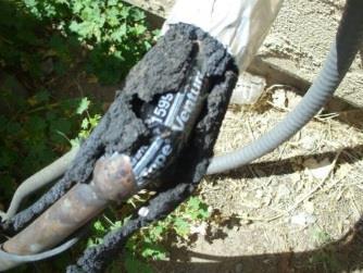
38 ACQC Assessment Condensers that are 15% or more deteriorated may not participate in a Refrigeration Charge Adjustment unless properly repaired when practical, or replaced. Refrigeration Charge Adjustment can be performed at anytime after the Assessment has been performed as long as the home is still eligible under the ACQC Program and that the External Static Pressure is between 0.5 and 1.0 IWC. 37
39 ACCA Standard 4 Requirements Documentation (Section 5.0) for the maintenance program should include at least: Inventory of the HVAC equipment, controls, components and accessories A list of inspection and maintenance tasks Code violations Performance objectives External conditions Inaccessible items Catastrophic duct disconnects or blockages Zoning controls and/or bypass issues Recommended corrective actions 38
40 Maintenance Inspection Tasks Quality Maintenance Program Requires Completion of the following ACCA 4 Checklists: Checklist Equipment 7.1 Air Distribution System 7.3 Gas Furnace 7.6 Evaporator Coil 7.7 Condensing Unit 39
41 Checklist 7.1 Air Distribution

42 CEC Title 24 Ducts Sheet metal duct and collar sealing 41

43 CEC Title 24 Ducts Sheet metal fittings to flex duct connections using Mastic 42

44 CEC Title 24 Ducts Sheet metal fittings to flex duct connections using Mastic 43
45 CEC Title 24 Ducts Proper flex duct mounting and routing to maintain aerodynamic air flow 44

46 7.1 The Air Distribution System More than 30% of Residential ductwork falls short when we consider Sizing, Sealing, Routing, and Insulation Problems in these areas lead to a host of problems including: Hot and cold zones in the home Increased energy costs Decreased indoor air quality 45
47 7.1 The Air Distribution System Duct Air Flow Capacity Assessment Foundation for Duct Retrofit and Restoration Duct system assessment Visual inspection Return plenum ducts Supply plenum ducts Inspect all duct, plenum, and boot connections for proper seal Turn on blower in high speed or cooling mode and check for air flowing out of each register 46
48 7.1 The Air Distribution System Duct system assessment Inventory duct sizes to achieve a minimum of 350 cfm/ton. Record filter size and return air register size in SA Mobile to determine if it is sized correctly. Open all registers when testing airflow to ensure air is being supplied to all registers. 47

49 System Assessment Test In The first section you will need to complete is the Test In Section This is the as found condition of the equipment on site Any improvements or repairs will be listed here for discussion with the homeowner Tap on 7.1 Air Distribution System to get started 48
50 CFM/Nominal Ton Dry Climate Cooling System Airflow (California)

51 7.1 The Air Distribution System Walking through SA Mobile s Air Distribution Checklist will bring to the surface everything that a home s duct system might need. This check list focuses on the systems: Filter type and airflow potential Supply and Return Sizing Need for sealing Insulation 50
52 7.1 The Air Distribution System Procedure Sum potential air flow using SA Mobile Air Distribution Test In 7.1 Compare to target air flow (350 cfm/ton) Done for both supply and return Determine filter grill or return grill size and filter size If automatic damper zoning installed follow enhanced procedures (test with both zones open and check the functionality of the zone system) Enter supply and return duct sizing in SA Mobile and the condition of all duct connections in Air Distribution Test In
53 Three Types of Pressure 1. STATIC Bursting pressure. The pressure exerted against the sides of the duct. 2. VELOCITY The pressure created by the flow of air through the duct. 3. TOTAL The combined effect of both static and velocity pressure. 52
54 External Static Pressure This is a combination of all the static pressure (return and supply) outside of the air handler. Abbreviated as ESP. Return pressure, which is negative, and supply pressure, which is positive, is added together without regard for positive or negative to arrive at the total external static pressure. Every furnace and air handler has a blower performance table. 53
55 External Static Pressure (cont.).5 in External Static Pressure is the Total Difference Between Supply and Return Pressure. 54

56 Probe Locations The supply probe is installed at the supply discharge of the air handler with the probe pointing into the supply air stream. The return probe is installed at the return air entry point of the air handler with the probe pointing into the return air stream. 55
57 Pressure Drop, IWC Cooling Airflow External Static Pressure by Component Supply 0.8 Coil 0.6 Return

58 7.1 The Air Distribution System: The Filters SA Mobile s Filter Calculations evaluate the filter(s) impact on the system by determining the airflow potential and comparing it to the system s requirements. We begin by counting the number of stand alone filters and filter returns and entering them in to SA Mobile. 57
: 16 Media Dimensions - Nominal Length (in.): 25 Media Dimensions - Nominal Thickness (in.): 5 Media Dimensions - Actual Width (in.): 15-3/4 Media Dimensions - Actual Length (in.")
59 Example Filter Trion Air Bear MERV 8 Media Filter Replacement 5 in. x 16 in. x 25 in. (3/Case) Installation Location: Filter Cabinet Media Dimensions - Nominal Width (in.): 16 Media Dimensions - Nominal Length (in.): 25 Media Dimensions - Nominal Thickness (in.): 5 Media Dimensions - Actual Width (in.): 15-3/4 Media Dimensions - Actual Length (in.): 24-1/4 Media Dimensions - Actual Thickness (in.): 5 MERV Rating: 8 Rated Air Flow (CFM): 1400 Pressure Drop at 600 CFM (in. W.C.): 0.04 Pressure Drop at 800 CFM (in. W.C.): 0.08 Pressure Drop at 1000 CFM (in. W.C.): 0.12 Pressure Drop at 1200 CFM (in. W.C.): 0.18 Pressure Drop at 1400 CFM (in. W.C.): 0.24 Cross Reference / Fits Models:

60 Table C (For new duct installation)

61 Table D (For new duct installation)
62 Common Pressure Drops (PD) Component Cooling coil Filters Pleated Filters Electrostatic Filters Disposable RA Grilles and SA Diffusers ACCA Manual D Transitions, Boots Elbows, (Use Turning Vanes) Pressure Drops IWC
63 62 Interesting Report prepared by Davis Energy Building America 2009 Annual Report Consortium for Advanced Residential Buildings

64 63 Interesting Report prepared by Davis Energy Building America 2009 Annual Report Consortium for Advanced Residential Buildings
65 64 Interesting Report prepared by Davis Energy Building America 2009 Annual Report Consortium for Advanced Residential Buildings

66 7.1 The Air Distribution System The Return The System Return Select the duct connection and location from the appropriate drop down menu Count the number of return air duct trunks and enter a quantity in the space provided Select the shape of the duct from the drop down menu Next enter the dimensions for each trunk 65

67 7.1 The Air Distribution System The Supply The System Supply Select the duct location from the appropriate drop down menu Count the number of supply duct trunks and enter a quantity in the space provided Select the shape of the duct from the drop down menu Next enter the dimensions for each trunk 66

68 7.1 The Air Distribution System The Inspection The Inspection Section Please note the filter type Inspect the supply plenum, connections, and seams Inspect for disconnected ducts Inspect platform returns In situations where the technician finds any of these areas to be unacceptable a proposed solution will be entered in the space provided 67

69 7.1 The Air Distribution System The Inspection Duct Sizing As it turns out, undersized duct systems with highfriction fittings, major air leaks, excessive run lengths, and crippling twists, kinks, and bends are the norm in the U.S., not the exception. A 1994 Department of Energy study estimated that nationwide, heating and cooling systems were operating at 60% of the designed airflow because of undersized ductwork. 68

70 CEC Title 24 Ducts Flex Duct R-values for various insulation thicknesses 69
71 Duct System Repair All work to use UL181 materials and T24 standards approved methods. All accessible duct work treated Major sites of leakage Take-off collars on plenums where are the highest pressures Sheet metal fittings Duct board triangles and boxes Boot connection to duct and gap between boot and drywall or floor 70
72 Duct System Repair (cont.) Duct mounting for aerodynamic airflow Runs are straight No kinks or twisted turns Flex ducts are fully extended Insulation R-4.2 minimum (Existing insulated Ducts) R-6.0, R-8.0 zone dependent (New Duct) Plenums insulated Outer jacket in place 71

73 72 Supplies and Returns/ Number and Diameter


74 Hall of Shame We want to see your before and after pictures for the Duct Restoration Hall of Fame 73
75 Checklist 7.3 Gas Furnace

76 Gas Furnace The ACCA 4 Inspection of the Gas Furnace is a visual inspection of the combustion device including it's Cabinet, Electrical Components, Blower Assembly, Condensate Removal, Gas Combustion and Ventilation to ensure these areas are all in safe, operating order. 75
77 Checklist 7.6 The Evaporator Coil
78 7.6 The Evaporator Coil During the Service the technician should inspect: Condition of the cabinet and fasteners Condition of the condensate pan and drain line The condition of the condensate pump The production of condensate For any signs of refrigerant leaks The suction line insulation The evaporator fins: Clean and Straight? TXV sensing bulb mounting and insulation if applicable 77
79 7.6 The Evaporator Coil With system OFF Ensure fins are straight Clean to remove debris blocking air flow Inspect refrigerant line, joints, components and coil for signs of leakage. Insulate refrigerant suction line If TXV present attach and insulate per program requirements With system ON Measure dry bulb temperature difference across the coil Measure pressure difference between the supply and return plenums 78

80 7.6 The Evaporator Coil SA mobile s Evaporator Coil Checklist follows the ACCA Standard 4 section 7.4. During the inspection the technician evaluate the components that make up the evaporator section. Each component will be deemed as acceptable or unacceptable. In cases where Unacceptable is the choice a proposed solution will be noted. 79
81 Checklist 7.7 The Condensing Unit
82 7.7 The Condensing Unit During the Service the technician should inspect: Cabinet integrity Electrical Refrigeration Fan Motor Coil Heat Pump 81
83 7.7 The Condensing Unit During the Service the technician should inspect: Condition of the Cabinet and fasteners Clearance around unit Electrical Supply and Disconnect The Equipment Grounding The Supply Voltage The compressor s amp draw The fan motor s amp draw The condition of the fan blades 82
84 7.7 The Condensing Unit With system OFF Verify and repair as needed: Cabinet Electrical disconnect meets code and is functional Grounding meets code and is correctly wired All wiring connections tight and repair as needed Capacitors and contactors Condenser coil Ensure fins are straight Clean or wash coil to remove debris blocking air flow Inspect refrigerant line, joints, components and coil for signs of leakage 83

85 7.7 The Condensing Unit During the Service the technician will record their findings in SA Mobile. 84
86 7.7 The Condensing Unit SA mobile s Condensing Unit Checklist follows ACCA Standard 4 section 7.7 During the inspection the technician evaluate the components that make up the condenser Each component will be deemed as acceptable or unacceptable In cases where Unacceptable is the choice a proposed solution will be noted Wash condenser coil upon inspection Straighten fins if necessary 85
87 7.7 The Condensing Unit With system On Electrical Measure and record incoming line voltage both high and low Measure and record amp draw of unit, compressor and fan motor Refrigeration System Diagnostic Procedure Measure indoor and outdoor temperatures and only continue if they are within the range required by the diagnostic software tool 86
88 7.7 The Condensing Unit With system On (cont.) Refrigeration System Diagnostic Procedure (cont.) Attach program approved gages and probes as directed by program protocol Run at least 15 minutes or until steady state operation is achieved Take the required readings Follow the software tool directions to first determine faults and then to correct them in the right order Complete final test showing the state of the refrigeration system 87
89 Refrigeration Cycle Testing
90 Refrigeration Cycle Test Refrigerant Charge Adjustment (RCA) can only be performed after the Assessment. In the event the condenser has 15% or greater damage, or deterioration, then a Refrigeration Cycle Test can not be performed. Total external Static Pressure must be between 0.5 and 1.0 IWC in order to proceed with RCA. 89
91 Refrigerant Charge Adjustment Prior to performing the Refrigerant Charge Adjustment: The condenser may not exceed 15% damage The condenser must be washed Suction line must be completely insulated And the total static pressure must be.5 to 1.0 iwc prior to performing Refrigeration Adjustment. Locking Caps are REQUIRED only after performing a Refrigerant Charge Adjustment 90

92 Refrigerant Charge Acceptable Unacceptable 91

93 Straighten Bent Fins Straighten bent or damaged fins. 92

94 93 Determining Condenser Corrosion/Damage Measure the total surface area of the condenser in square inches Measure the damaged or corroded section(s) in square inches Divide the damaged area by the total area and multiply by 100 to determine percent of damage Example: 37in sq. damaged. 418in sq total surface area. 37/418 =.088 X 100 = 9% damage. OK to perform Refrigerant Charge Adjustment
95 Refrigerant and the Compressor Superheat is the heat absorbed into a substance over its saturation temperature The temperature over the boiling point The difference between the temperature we estimate from measuring the suction pressure and the temperature of the suction line entering the compressor 94

96 The Condenser The refrigerant enters as a hot gas that is cooled to the saturation temperature in the De-Superheating section The Condensing section is where the refrigerant vapor becomes a liquid The Subcooling section is where the liquid is cooled down further 95

97 The Condenser Subcooling is the measure of the heat rejected from a substance below its saturation temperature The temperature below the condensing point The difference between the temperature we estimate from measuring the high- side pressure and the temperature of the liquid line leaving the condenser 96
98 The Refrigerant Diagnostic System
99 Example of Refrigerant Diagnostic LT ST DB WB 80 MR1 98

100 Example of Refrigerant Diagnostic LT ST DB WB 80 MR1 99
101 Fault Detection and Diagnostics Overview High side evaluation Low side evaluation Ambient temperature SA Mobile Fault Detection 100

102 Refrigeration Cycle Testing SA Mobile uses all of the required inputs and calculate four indices used to evaluate a systems performance relative to an expectation at the current operating conditions. ET = Evaporating Temperature SH = Superheat COA = Condensing Temperature Over Ambient SC = Subcooling 101
103 Refrigeration Cycle Testing Safe and Reasonable Performance All four of the indices are within the acceptable range indicating that there is now further work to do. Systems in this condition are more likely to provide reliable performance and capacity for your customer throughout the cooling season. Comfort and Reliability is what your Customer wants. 102
104 High Side Evaluation COA - Condensing Temperature Over Ambient Causes of high COA Dirty or blocked Coil Damaged coil Condenser fan problem Overcharge Non condensables Causes of low COA Undercharge Liquid line restriction 103
105 High Side Evaluation SC Sub-cooling Causes of high sub-cooling Overcharge Liquid line Restriction Causes of low sub-cooling Undercharge 104
106 High Head Pressure There are three primary causes for high head pressure. 1) High side heat transfer problem 2) Overcharge 3) Noncondensables COA Condensing Temperature Over Ambient 105
107 High Head Pressure 1) High side heat transfer problem This means the condenser is hot with no sign of over charge. SA Mobile doesn t know if the condenser fans are running. A high condenser air T with running fans proves a dirty condenser. 106

108 High Head Pressure 2) Overcharge When the sub-cooling is high it means the refrigerant charge is excessive. 107
109 High Head Pressure 3) Non-Condensables A high condenser air T with running fans proves a dirty condenser If T is not hot, a standing pressure test will prove noncondensables Non-condensables are unusual but not rare 108
110 High Head Pressure What about liquid line restrictions? Restrictions reduce the refrigerant flow to the evaporator This reduces the amount of heat absorbed in the evaporator With less heat to reject, the condenser is large compared to it s heat load Head pressure is lower 109
111 Low Side Evaluation ET - Evaporator Temperature Causes of high Evaporating Temperature Overcharge Too much airflow or load Causes of low Evaporating Temperature Undercharge or Low side heat transfer problem Filters Dirty fan Closed and/or blocked registers Dirty and/or blocked coil Undersized ductwork 110
112 111 Nomenclature SP LP (ET) (CT) ST LT AMB RA RWB SA SWB COA RTU AHU Suction Line Pressure Liquid Line Pressure Evaporator Pressure/Temperature Conversion Condenser Pressure/Temperature Conversion Suction Line Temperature Liquid Line Temperature Ambient Condensing Unit Return Air Dry Bulb Temperature Return Air Wet Bulb Temperature Supply Air Dry Bulb Temperature Supply Air Wet Bulb Temperature Condenser Over Ambient Rooftop Unit Air Handling Unit
113 Inspections
114 Inspection Frequencies If unacceptable conditions or performance are found during two successive inspections (Section 7.4.2) The owner should be notified and possible causes should be investigated, such as: Poor field practices Insufficient time budgeted for task Repairs pending such as refrigerant leakage resulting in reoccurring low charge Design issues Obsolete equipment External factors 113
115 Inspection Frequencies QM Agreement Rebate Two Seasonal visits are required, but depending on investigation, inspection frequency or maintenance task, this may need to be adjusted. Only if the customer elects to sign the QM Agreement. 114
116 PG&E Approved Motors & Relays

117 Approved Blower Motor Replacement PG&E has approved the following permanent magnet motors: 116

118 Approved Fan Delay Relays PG&E has approved the following fan delay relays: 117
119 PG&E Approved Tools
120 HVAC Residential Instrumentation Technicians will be required to use instruments that meet the minimum accuracy requirement of the program They will include: Temperature analyzers to read wet and dry bulb temperatures Digital manifold sets Multi-meters to read voltage and amperage Digital manometers 119
121 Instrument Accuracy Digital Manifold Lo Side + 1 PSI Hi Side + 3 PSI Digital Temperature Analyzer Degrees Fahrenheit Digital Manometer Inches of Water Column (IWC) 120


122 Digital Temperature Analyzer and Probe Temperature Analyzer with Dry and Wet Sock Probes 121

123 Digital Manifold Set Digital Manifold (less hoses and thermocouples) 122

124 123 Volt/Amp Multi-Meters


125 Digital Manometer-Test Equipment Dwyer Series 475 Mark III UEI EM200 Retrotec DM2 Energy Conservatory DG 700 Either Digital or Analog test equipment are acceptable as long as they are approved by this program 124
126 Toolbox Safety Topics


127 Safety Topics Covered Think Safety First when out in the field! Electrical Safety Ladder Safety Tool Safety 126
128 Electrical Safety Did you know that over 1,000 workers are killed by electricity annually with another 30,000 plus injured? This is from working or coming in contact with live electrical without proper protection or not having turned off the power prior to the start of work. 127
129 Electrical Safety Severe electrical shock can cause the following serious, and life threatening injuries. Ventricular fibrillation resulting in cardiac arrest Loss of limbs and eyes Severe burns, tissue damage, muscle damage and kidney failure 128

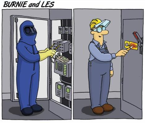
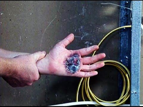
130 129 Electrical Safety
131 Electrical Safety Death by electrocution resulting in ventricular fibrillation, doesn t need a lot of current. It only takes about 100 milliamps for a few seconds running through your body to cause Ventricular fibrillation and kill you, compare this to a 100 watt light bulb which is about 909 milliamps. 130


132 Electrical Safety Electrical hazards can be in the home and in crawl spaces so be alert and watch out. 131


133 Electrical Hazards to Avoid Electrical hazards can be in the home and in crawl spaces so be alert and watch out. 132

134 133 Proper Ladder Safety


135 134 Improper Ladder Use
136 Tool Safety Eye injuries are quite common. Metal shavings from drilling or grinding, or wire bristles from wire brushes can fly off and enter the eye that is why eye protection should always be worn. Power saws can cause amputations of fingers or limbs. Broken bones and head injuries can result from tools falling from heights. A tool falling from above on an unprotected head could be lethal always wear a hard hat. 135


137 136 Tool Safety: Protect Eyes and Limbs


138 137 Tool Safety: Be Aware of What You Are Doing

139 Questions and Answers WHY ARE HOME AIR CONDITIONERS A LOT LIKE CARS? THEY BOTH RUN BETTER AFTER A TUNE-UP. 138

140 139 Questions before the Quiz
AC Quality Care Rebate Program. Technical Training and SA Mobile Introduction
 AC Quality Care Rebate Program Technical Training and SA Mobile Introduction Title 24 Slides Throughout this presentation the LOGO in the upper right corner indicates the information presented is part
How to Take Basic Readings to Show Energy Efficiency
 How to Take Basic Readings to Show Energy Efficiency NADCA Energy White Paper Readings & Copyright 2017 NADCA, All Rights Reserved No part of this publication may be reproduced or distributed by any means,
SERVICE ASSISTANT OVERVIEW FDSI Online Training
 Author: Dale T. Rossi Online Editor: Zachary Williams SERVICE ASSISTANT OVERVIEW FDSI Online Training May 5, 2009 Table Service Assistant Description... 2 Installing the Main Unit... 3 Ambient Temperature...
Published by the California Building Performance Contractors Association
 TO THE FOR PRESCRIPTIVE COMPLIANCE OF FOR RESIDENTIAL ALTERATIONS The to the 2008 Energy Code for prescriptive compliance for Refrigerant Charge & Airflow for residential alterations is a guide for those
Technical Standards for the Air Conditioning and Heat Pump Professional BPI STANDARDS
 Technical Standards for the Air Conditioning and Heat Pump Professional BPI STANDARDS THE SYMBOL OF EXCELLENCE FOR HOME PERFORMANCE CONTRACTORS VERSION 1.1, FEBRUARY 2003 TABLE OF CONTENTS: TECHNICAL STANDARDS
Table of Contents. Service Procedures. Service Procedures. Measuring Superheat (4) Measuring Subcooling (5) Airflow Calculation (6-8)
 Measuring Subcooling (5) Airflow Calculation (6-8)") Table of Contents Refrigeration Cycle Service Procedures Measuring Superheat (4) Measuring Subcooling (5) Airflow Calculation (6-8) Solving Problems Identifying Low System Charge (9-11) Identifying High
Table of Contents Refrigeration Cycle Service Procedures Measuring Superheat (4) Measuring Subcooling (5) Airflow Calculation (6-8) Solving Problems Identifying Low System Charge (9-11) Identifying High
ENERGY STAR Qualified Homes
 ENERGY STAR Qualified Homes HVAC SYSTEM QUALITY INSTALLATION RATER CHECKLIST 1 For Version 3 Part 2 of HVAC Quality Installation PRESENTED BY: Rocky Mountain Power wattsmart New Homes Program & Questar
TO THE FOR PRESCRIPTIVE COMPLIANCE OF FOR RESIDENTIAL ALTERATIONS
 TO THE FOR PRESCRIPTIVE COMPLIANCE OF FOR RESIDENTIAL ALTERATIONS The to the 2013 Energy Code for prescriptive compliance for HERS required measures for residential alterations is a guide for those who
For an administrative fee of $9.97, you can get an un-locked, printable version of this book.
 The System Evaluation Manual and Chiller Evaluation Manual have been revised and combined into this new book; the Air Conditioning and Refrigeration System Evaluation Guide. For an administrative fee of
Instructors: Contact information. Don Reynolds Doug McGee Factory Tech Support
 Contact information Instructors: Don Reynolds 616-560-9903 Doug McGee 517-294-3932 Factory Tech Support 888-593-9988 Product Improvements for 2017 Todays Objectives Job Site Information Sheets Low Ambient
Duct Design and Installation
 Duct Design and Installation John Proctor, P.E. Proctor Engineering Group, Ltd. San Rafael, CA 2004 Proctor Engineering Group, Ltd. 1-888-455-5742 mail@proctoreng.com www.proctoreng.com Duct Design ACCA
HVAC Systems What the Rater Needs to Know in the Field CALCS-PLUS
 HVAC Systems What the Rater Needs to Know in the Field This presentation used CASE* studies from the following *CASE Copy And Steal Everything HVAC Systems - What the Rater Needs to Know in the Field This
In the past, contractors sized heating and cooling systems GETTING HVAC RIGHT
 GETTING HVAC RIGHT Calculating loads is just the first step. For a trouble-free system that s long on comfort, you need to specify the equipment, design the ductwork, and make certain everything is correctly
Service Step by Step Trouble-Shooting Check-List
 WARNING: Only Data Aire trained technician or experience technicians should be working on Data Aire Equipment. Protect yourself at all times and work safe. Date: Dates at the job site: From: to Job#: Serial#:
Otherwise, you can continue reading the file on the following pages.
 If you d like to be able to print this file out to study off-line or use on the job, a printable version is available for an administrative fee of $3.97 USD. To download the unlocked file, click here.
Certification Information. Qualifications. Test Specifications
 AIR CONDITIONING INSTALLATION CERTIFICATION Certification Information Scope - Tests a candidate's knowledge of the installation, service, maintenance, and repair of HVAC systems. System sizes are limited
Warm Case Troubleshooting Guide 9/18/2014
 Introduction Warm cases can be caused by various problems which require thorough troubleshooting. Begin the investigation with questions to store personnel asking for information such as when the last
2016 BUILDING ENERGY EFFICIENCY STANDARDS RESIDENTIAL HVAC ALTERATIONS
 B 2016 BUILDING ENERGY EFFICIENCY STANDARDS RESIDENTIAL HVAC ALTERATIONS COMMUNITY DEVELOPMENT DEPARTMENT 345 N. EL DORADO STREET STOCKTON, CA 95202 (209) 937-8561 www.stocktongov.com/cdd/building BUSINESS
wattsmart New Homes Contractor-Certified HVAC Quality Assurance (HVAC-QI)
") Contractor-Certified HVAC Quality Assurance (HVAC-QI) HVAC Quality Assurance (HVAC-QI) Checklists The following checklists are required, with all applicable items completed and checked, including final
Contractor-Certified HVAC Quality Assurance (HVAC-QI) HVAC Quality Assurance (HVAC-QI) Checklists The following checklists are required, with all applicable items completed and checked, including final
Introduction to HVAC. American Standard Inc Air Conditioning Clinic TRG-TRC018-EN
 Introduction to HVAC Agenda Psychrometrics Human Comfort Heat Transfer Refrigeration Cycle HVAC Terminology HVAC Systems Introduction to HVAC Psychrometrics 2000 TRG-TRC002-EN Properties of Air Dry-bulb
Installation Instructions
 Installation Instructions PAM3 SERIES PACKAGE AIR CONDITIONERS TABLE OF CONTENTS SAFETY LABELING AND SIGNAL WORDS... 2 UNIT DIMENSIONS... 3 SAFE INSTALLATION REQUIREMENTS... 3 LOCATING THE UNIT... 3 CLEARANCES...
City of Duluth Festival Center 04/25
 SECTION 230593 - TESTING, ADJUSTING, AND BALANCING FOR HVAC PART 1 - GENERAL 1.1 RELATED DOCUMENTS A. Drawings and general provisions of the Contract, including General and Supplementary Conditions and
VERTICAL AHU INSTALLATION MANUAL BULLETIN
 VERTICAL AHU INSTALLATION MANUAL BULLETIN 30-015003 TABLE OF CONTENTS MOUNTING 4 LOCATION 5 DUCT CONNECTION 5 AIR FILTRATION 6 PIPING 7 SEQUENCE OF OPERATION 11 CHECKING AIRFLOW 11 CHARGING A COOLING SYSTEM
HVAC for Raters & Inspectors
 HVAC for Raters & Inspectors A Practical Overview of HVAC Impacts On Home Performance With Useful Take-Away Tools Presenter: David Slater 2010 Stream Residential LLC. All Rights Reserved. February 23,
Promoting quality installation of central AC (and heat pump) systems
 systems") Promoting quality installation of central AC (and heat pump) systems Energy Design Conference and Expo Duluth, MN February 26, 2014 and gas furnaces In accordance with the Department of Labor and Industry
Promoting quality installation of central AC (and heat pump) systems Energy Design Conference and Expo Duluth, MN February 26, 2014 and gas furnaces In accordance with the Department of Labor and Industry
INSTALLATION INSTRUCTIONS Cased N Coil, Horizontal ENH4X
 INSTALLATION INSTRUCTIONS Cased N Coil, Horizontal ENH4X NOTE: Read the entire instruction manual before starting the installation. TABLE OF CONTENTS PAGE SAFETY CONSIDERATIONS... 1 INTRODUCTION... 1 INSTALLATION...
Installation Guide. Dehumidification. Fresh Air Ventilation. Compact Size. Energy Efficient. RXID-AW90A Whole House Dehumidifier
 RXID-AW90A Whole House Dehumidifier with fresh air ventilation Installation Guide Dehumidification Fresh Air Ventilation Compact Size Energy Efficient The whole house dehumidifier integrates highcapacity
CROWN. Boiler Co. Santa-Fe Series. Hydronic Air Handlers INSTALLATION, OPERATION & MAINTENANCE INSTRUCTIONS
 CROWN Boiler Co Santa-Fe Series Hydronic Air Handlers INSTALLATION, OPERATION & MAINTENANCE INSTRUCTIONS These instructions must be affixed on or adjacent to the air handler Models: SAC049A20 SAC059A25
Residential Quality Maintenance Unitary Air Conditioner Fault Detection & Diagnostics
 Residential Quality Maintenance Unitary Air Conditioner Fault Detection & Diagnostics ET Project Number: ET11PGE5261 Project Manager: Marshall Hunt, P.E. Pacific Gas and Electric Company Prepared By: Marshall
In accordance with the Department of Labor and Industry s statute , Subd. 11,
 In accordance with the Department of Labor and Industry s statute 326.0981, Subd. 11, This educational offering is recognized by the Minnesota Department of Labor and Industry as satisfying 1 hours of
INSTALLATION INSTRUCTIONS TXV Horizontal Duct Coils EHD
 TXV Horizontal Duct s EHD These instructions must be read and understood completely before attempting installation. It is important that the Blower and Duct System be properly sized to allow the system
Capt. Tim s s Duct Design Mythbusters. The bitterness of poor quality is remembered long after the sweetness of low price is forgotten!
 Capt. Tim s s Duct Design Mythbusters The bitterness of poor quality is remembered long after the sweetness of low price is forgotten! WHY CARE ABOUT THE DUCTS? Human Comfort Zone (After All, it s s only
UNDERSTANDING AND USING THE HVAC DESIGN REVIEW FORM
 Page 1 UNDERSTANDING AND USING THE HVAC DESIGN REVIEW FORM Each of the 38 points of requested information is discussed, and references to the supporting manual are given to substantiate the requirement.
Union County Vocational - Technical Schools Scotch Plains, New Jersey
 SECTION 230593 - TESTING, ADJUSTING, AND BALANCING FOR HVAC PART 1 - GENERAL 1.1 SUMMARY A. Section Includes: 1. Balancing Air Systems: a. Constant-volume air systems. b. Variable-air-volume systems. 2.
When Duct Sealing Kills HVAC Equipment and Efficiency
 When Duct Sealing Kills HVAC Equipment and Efficiency National Comfort Institute is an international training and development company headquartered in Cleveland, Ohio, with offices in Nashville, Tennessee,
INSTALLATION INSTRUCTIONS TXV Coils EDM, EDD, EDA
 TXV Coils EDM, EDD, EDA These instructions must be read and understood completely before attempting installation. It is important that the Blower and Duct System be properly sized to allow the system to
INSTALLATION INSTRUCTIONS
 2011 Lennox Industries Inc. Dallas, Texas, USA INSTALLATION INSTRUCTIONS 13HPP UNITS PACKAGED HEAT PUMP UNIT (2 5 TONS) 506750 01 06/11 Supersedes 03/11 Litho U.S.A. RETAIN THESE INSTRUCTIONS FOR FUTURE
Have you downloaded the groovy show App? Search in the Apple App store or the Google Play Store for Everything Under the Sun
 Have you downloaded the groovy show App? Search in the Apple App store or the Google Play Store for Everything Under the Sun Don t forget to complete surveys at the end of each class. You can complete
INSTALLATION INSTRUCTIONS Cased N Coil, Horizontal ENH4X
 INSTALLATION INSTRUCTIONS Cased N Coil, Horizontal ENH4X NOTE: Read the entire instruction manual before starting the installation. TABLE OF CONTENTS PAGE SAFETY CONSIDERATIONS... 1 INTRODUCTION... 1 INSTALLATION...
SECTION 7 AIR CONDITIONING (COOLING) UNIT 41 TROUBLESHOOTING
 UNIT 41 TROUBLESHOOTING") SECTION 7 AIR CONDITIONING (COOLING) UNIT 41 TROUBLESHOOTING UNIT OBJECTIVES After studying this unit, the reader should be able to Select the correct instruments for checking an air conditioning unit
SECTION 7 AIR CONDITIONING (COOLING) UNIT 41 TROUBLESHOOTING UNIT OBJECTIVES After studying this unit, the reader should be able to Select the correct instruments for checking an air conditioning unit
INSTALLATION INSTRUCTIONS
 INSTALLATION INSTRUCTIONS T CLASS TSA Series 6 to 20 Ton AIR CONDITIONERS 6 20 TONS 506147 01 06/11 Supersedes 3/11 Litho U.S.A. RETAIN THESE INSTRUCTIONS FOR FUTURE REFERENCE IMPORTANT The Clean Air Act
Field Manual Models: HG1 & HG2. v.38
 Field Manual Models: HG1 & HG2 ELDPIECE.COM WWW.FIELDPIECE.COM WWW.FIELDPIECE.COM WWW.FIELDPIECE.COM WWW.FIELDPIECE.COM WWW.FIELDPIECE v.38 HVAC Guide Analyzer Field Manual HG1 & HG2 Do it right the first
SEVEN STEPS TO EFFECTIVE PRE- SEASON COOLING CHECKUPS
 SEVEN STEPS TO EFFECTIVE PRE- SEASON COOLING CHECKUPS by Dennis Kalchuk While temperatures are still tolerable, it's time to prepare your customers' systems to deal with the blasts of summer heat and humidity
Mortex INSTALLATION INSTRUCTIONS AIR CONDITIONING & HEAT PUMP INDOOR COILS
 Mortex INSTALLATION INSTRUCTIONS AIR CONDITIONING & HEAT PUMP INDOOR COILS INTRODUCTION Please note that HUD Manufactured Home Construction and Safety Standard Section 3280.714, paragraph (a) and subparagraph
SECTION 8 AIR SOURCE HEAT PUMPS UNIT 43 AIR SOURCE HEAT PUMPS
 SECTION 8 AIR SOURCE HEAT PUMPS UNIT 43 AIR SOURCE HEAT PUMPS UNIT OBJECTIVES After studying this unit, the reader should be able to Describe the operation of reverse-cycle refrigeration (heat pumps) Explain
Liebert Small System MCD and PFH Condensers (1-5 Ton) Warranty Inspection Check Sheet
 Warranty Inspection Check Sheet") The following information must be fully completed and forwarded to your local Liebert sales office to establish your equipment warranty. Installer Address Owner Address Owner e-mail address Installation
The following information must be fully completed and forwarded to your local Liebert sales office to establish your equipment warranty. Installer Address Owner Address Owner e-mail address Installation
Cased Aluminum Coils "Dedicated Upflow / Downflow" Convertible to horizontal with separately purchased kit
 18-AD32D1-3 Cased Aluminum Coils "Dedicated Upflow / Downflow" Convertible to horizontal with separately purchased kit Upflow models: 4PXCAU24BS3HAA 4PXCBU24BS3HAA 4PXCBU30BS3HAA 4PXCCU30BS3HAA 4PXCBU36BS3HAA
HEALTHY HOME AIR PURIFICATION SYSTEM
 HEALTHY HOME AIR PURIFICATION SYSTEM MODELS: TRIO 1200 & TRIO 2000 INSTALLATION AND OPERATION Field Controls, 2630 Airport Road, Kinston, NC 28504 *(252)522-3031* www.fieldcontrols.com Table of Contents
AIR CONDITIONING. Carrier Corporation 2002 Cat. No
 AIR CONDITIONING Carrier Corporation 2002 Cat. No. 020-016 1. This refresher course covers topics contained in the AIR CONDITIONING specialty section of the North American Technician Excellence (NATE)
Supplement A- Improving Forced Air Heating Systems
 Supplement A Improving Forced Air Heating Systems The Challenge Recent research and testing of new homes in the Pacific Northwest and across the United States shows the importance of a properly installed
INSTALLATION INSTRUCTIONS TXV Coils EBU, EBA
 TXV s EBU, EBA These instructions must be read and understood completely before attempting installation. It is important that the Blower and Duct System be properly sized to allow the system to operate
INSTALLATION INSTRUCTIONS TXV Coils EBD, EBA
 TXV Coils EBD, EBA These instructions must be read and understood completely before attempting installation. It is important that the Blower and Duct System be properly sized to allow the system to operate
INSTALLATION INSTRUCTIONS
 INSTALLATION INSTRUCTIONS 13CHPX SERIES UNITS PACKAGED HEAT PUMPS (2 5 TONS) 505,136M (38152A071) 12/09 Supersedes 05/09 Litho U.S.A. RETAIN THESE INSTRUCTIONS FOR FUTURE REFERENCE WARNING Improper installation,
APPLICATION DATA SHEET
 APPLICATION DATA SHEET General Piping Recommendations and Refrigerant Line Length for Split-System Air Conditioners and Heat Pumps GENERAL GUIDELINES This Split-System (Air Conditioning Condensing/Heat
INSTALLATION MANUAL SINGLE PIECE STANDARD ECM AIR HANDLERS MODELS: AHX61 SERIES LIST OF SECTIONS LIST OF FIGURES LIST OF TABLES SECTION I: GENERAL
 INSTALLATION MANUAL SINGLE PIECE STANDARD ECM AIR HANDLERS MODELS: AHX61 SERIES GENERAL.............................................. 1 SAFETY................................................ 1 UNIT INSTALLATION.....................................
Installation Instructions
 CNPHP Cased N Coils Horizontal Heating --- Cooling NOTE: Read the entire instruction manual before starting the installation. TABLE OF CONTENTS PAGE SAFETY CONSIDERATIONS... 1 INTRODUCTION... 1 INSTALLATION...
Maintaining Packaged Rooftop Units
 Published on Business Energy Advisor (https://fpl.bizenergyadvisor.com) Home > Maintaining Packaged Rooftop Units Maintaining Packaged Rooftop Units Packaged air-conditioner and heat-pump systems, also
INSTALLATION INSTRUCTIONS Cased N Coil, Horizontal ENH4X
 INSTALLATION INSTRUCTIONS Cased N, Horizontal ENH4X NOTE: Read the entire instruction manual before starting the installation. SAFETY CONSIDERATIONS Improper installation, adjustment, alteration, service,
Experienced Worker Assessment Blueprint HVAC - Heating, Ventilation and Air Conditioning
 Blueprint HVAC - Heating, Ventilation and Air Conditioning Test Code: 0144 / Version: 02 Specific Competencies and Skills Tested in this Assessment: Electricity Demonstrate understanding of basic AC/DC
Technical Development Program. COMMERCIAL HVAC PACKAGED EQUIPMENT Split Systems PRESENTED BY: Ray Chow Sigler
 Technical Development Program COMMERCIAL HVAC PACKAGED EQUIPMENT Split Systems PRESENTED BY: Ray Chow Sigler Menu Section 1 Section 2 Section 3 Section 4 Section 5 Section 6 Section 7 Introduction System
INSTALLATION INSTRUCTION
 INSTALLATION INSTRUCTION MODULAR AIR HANDLER MODEL: N*AH CONTENTS GENERAL... 1 INSPECTION... 2 REFERENCE... 2 LIMITATIONS... 2 LOCATION... 2 BLOWER/COIL ASSEMBLY UPFLOW AND HORIZONTAL INSTALLATIONS...
Packaged Heat Pump. 20 Ton Rooftop Units with ReliaTel TM Controls NOTICE
 Service Facts Customer Property: Contains wiring and service information. Please retain. WC*240-SF-1H Library Service Literature Product Section Unitary Product Package Air Conditioner Model WC* Literature
power Describe the purpose of lockout/tag-out devices Demonstrate use of lockout/tagout
 c. All contestants are required to remain in the contest area until the contest has been torn down and excused by the Chairperson. Note: Your contest may also require a hard copy of your résumé as part
Your safety and the safety of others are very important.
 VARIABLE SPEED ELECTRIC FURNACE INSTALLATION INSTRUCTIONS VARIABLE SPEED ELECTRIC FURNACE SAFETY...1 INSTALLATION REQUIREMENTS...2 Tools and Parts...2 Location Requirements...2 Installation Configurations...3
System Components with ` Emphasis on Packaged Rooftop Application and Installation. Jerry Cohen President Jacco & Assoc.
 System Components with ` Emphasis on Packaged Rooftop Application and Installation Jerry Cohen President Jacco & Assoc. Agenda Define and relate in practical terms the following components: System Effect
INSTALLATION INSTRUCTIONS
 INSTALLATION INSTRUCTIONS T CLASS TPA Series HEAT PUMPS 7.5 TO 10 TONS 506148 01 12/08 Litho U.S.A. RETAIN THESE INSTRUCTIONS FOR FUTURE REFERENCE IMPORTANT The Clean Air Act of 1990 bans the intentional
INSTALLATION INSTRUCTIONS WALL MOUNTED PACKAGE AIR CONDITIONERS WA121
 INSTALLATION INSTRUCTIONS WALL MOUNTED PACKAGE AIR CONDITIONERS Model: WA121 Bard Manufacturing Company Bryan, Ohio 43506 Since 1914...Moving ahead just as planned. Manual : 2100-234 G Supersedes: 2100-234
TECHNICAL GUIDE MODELS: P*DH GAS-FIRED CONDENSING / HIGH EFFICIENCY DOWNFLOW / HORIZONTAL FURNACES 91 AFUE DESCRIPTION WARRANTY FEATURES
 036-1354-001 Rev. D (110) Heating TECHNICAL GUIDE MODELS: P*DH GAS-FIRED CONDENSING / HIGH EFFICIENCY DOWNFLOW / HORIZONTAL FURNACES 91 AFUE NATURAL GAS 37-111 MBH OUTPUT Air Conditioning EFFICIENCY RATING
INSTALLATION INSTRUCTIONS TXV Horizontal Slab Coils WLSH
 TXV Horizontal Slab Coils WLSH These instructions must be read and understood completely before attempting installation. It is important that the Blower and Duct System be properly sized to allow the system
Installation Instructions
 CNPHP Cased N s Horizontal Heating --- Cooling Installation Instructions NOTE: Read the entire instruction manual before starting the installation. TABLE OF CONTENTS PAGE SAFETY CONSIDERATIONS... 1 INTRODUCTION...
BasicTroubleshooting Information and Guidelines
 BasicTroubleshooting Information and Guidelines BasicTroubleshooting Information and Guidelines Information and Guidelines May 2017 BasicTroubleshooting PRIOR TO CONTACTING CLIMATEMASTER TECHNICAL SUPPORT,
INSTALLATION INSTRUCTIONS TXV Coils for Manufactured Housing EMA
 TXV Coils for Manufactured Housing EMA NOTE: Read the entire instruction manual before starting the installation. SAFETY CONSIDERATIONS Improper installation, adjustment, alteration, service, maintenance,
Electric Heat Inspection Form Revised September 2012
 Client name: Address: Primary Heat Source: Auxiliary Heat Application: Heat Pump Information: Equipment Information Electric Electric Heat Inspection Form Revised September 2012 Audit Existing furnace
P.O. Box , Dallas, TX USER'S INFORMATION MANUAL Single-Stage Warm Air Gas Furnaces
 P.O. Box 799900, Dallas, TX 75379-9900 USER'S INFORMATION MANUAL Single-Stage Warm Air Gas Furnaces This is a safety alert symbol and should never be ignored. When you see this symbol on labels or in manuals,
INSTALLATION INSTRUCTIONS TXV Horizontal Duct Coils EHD
 TXV Horizontal Duct s EHD These instructions must be read and understood completely before attempting installation. It is important that the Blower and Duct System be properly sized to allow the system
Packaged Gas/Electric Units. Owner s Guide to Operating and Maintaining Your Gas/Electric Unit
 Packaged Gas/Electric Units Owner s Guide to Operating and Maintaining Your Gas/Electric Unit ELECTRICAL SHOCK HAZARD. FIRE OR EXPLOSION HAZARD Disconnect power at fuse box or service panel before performing
USER S INFORMATION MANUAL
 2017 Lennox Industries Inc. Dallas, Texas, USA 506737-01 04/2017 Supersedes 03/2017 USER S INFORMATION MANUAL EL195UHE SERIES GAS FURNACE Improper installation, adjustment, alteration, service or maintenance
Ducted Heat Pump Program Equipment and Installation Specifications Site-Built and Manufactured Homes Exhibit A
 Ducted Heat Pump Program Equipment and Installation Specifications Site-Built and Manufactured Homes Exhibit A 1.0 GENERAL REQUIREMENTS... 3 1.1 INTERPRETATION OF SHALL AND SHOULD... 3 1.2 INSTALLATION
MODELS B1PA024, 030 AND 036
 STELLAR 2000 SINGLE PACKAGE HEAT PUMPS INSTALLATION INSTRUCTION Supersedes: 511.26-N1Y (892) 511.26-N1Y (893) MODELS B1PA024, 030 AND 036 035-11622 GENERAL YORK Model B1PA units are factory assembled heat
MANUAL J/S Summary One summary sheet for each system
 MANUAL J/S Summary One summary sheet for each system NOTE: The load calculation must be calculated on a room basis. Room loads are a mandatory requirement for making Manual D duct sizing calculations.
Venting of Gas Fired Equipment RV
 PLEASE DO NOT BOOKMARK ANY ANYTIMECE WEBPAGES! Our system will remember the last page you viewed when logging out and back in but please DO NOT exit out when taking a test. Your place will NOT be saved.
Event #1 Brazing. In this event you will demonstrate how to:
 Event #1 Brazing Read and interpret the refrigerant circuit drawing Follow all normal safety procedures Use proper brazing techniques to join tubing, fittings, and components Return all tools, instruments,
Installation Instructions
 FAVXXR6C2100-A01 Vent Damper and Control Installation Instructions FAMILIARIZE YOURSELF WITH THE INSTALLATION INSTRUCTIONS BEFORE STARTING ATTENTION INSTALLER: This product must be installed by a qualified
Laboratory Measurements and Diagnostics of Residential HVAC Installation and Maintenance Faults
 Laboratory Measurements and Diagnostics of Residential HVAC Installation and Maintenance Faults Robert Mowris, Ean Jones, and Robert Eshom, Robert Mowris & Associates, Inc. ABSTRACT Laboratory test results
Summary of Comments (Washington Revisions November 7, 2000) Update November 27, 2000
 Update November 27, 2000") SAE Alternate Refrigerant Cooperative Research Program Summary of Comments (Washington Revisions November 7, 2000) Update November 27, 2000 To: Alternate Refrigerant Task Force Members From: Ward Atkinson
SAE Alternate Refrigerant Cooperative Research Program Summary of Comments (Washington Revisions November 7, 2000) Update November 27, 2000 To: Alternate Refrigerant Task Force Members From: Ward Atkinson
Determining Real Time Performance of Residential AC Systems. Presented at the RESNET Conference San Antonio, TX February 28, 2006
 Determining Real Time Performance of Residential AC Systems Presented at the RESNET Conference San Antonio, TX February 28, 2006 Bill Spohn testo, Inc. testo Worldwide 100 90 80 70 60 50 40 30 20 10 0
USER S, MAINTENANCE and SERVICE INFORMATION MANUAL
 CONTENTS SAFETY INFORMATION................ 2 FOR YOUR SAFETY....................... 2 SYSTEM OPERATION.................. 2 THERMOSTATS.......................... 2 INTERMITTENT IGNITION DEVICE...........
INSTALLATION MANUAL UN-CASED A COILS UPFLOW FOR COOLING/HEAT PUMPS FLEX COILS FOR FIELD INSTALLED TXV MODELS: UC LIST OF SECTIONS LIST OF FIGURES
 INSTALLATION MANUAL UN-CASED A COILS UPFLOW FOR COOLING/HEAT PUMPS FLEX COILS FOR FIELD INSTALLED TXV MODELS: UC ISO 9001 Certified Quality Management System SAFETY................................................
KGA092 SHOWN READ ALL INSTRUCTIONS IN THIS MANUAL AND RETAIN FOR FUTURE REFERENCE WARNING
 See unit nameplate for manufacturer and address. 506380 01 11/2009 KGA024, 030, 036, 048, 060, 072 (2, 2 1/2, 3, 4, 5, and 6 Tons) KGA092, 102, 120, 150 (7 1/2, 8-1/2, 10, and 12 Tons) KGA180, 210, 240,
Installation Guide.
 Installation Guide www.evergreendealer.com www.thedealertoolbox.com When Regal Beloit acquired General Electric s Commercial and HVACR Motors and Capacitors businesses in 2004, it also acquired the rights
Service Guide. Service Guide NATIONAL COMFORT PRODUCTS GAS & ELECTRIC MODELS. 2nd Edition
 2nd Edition Service Guide Thru-the-Wall Packaged Heating & Cooling Units Service Guide GAS & ELECTRIC MODELS NATIONAL COMFORT PRODUCTS HEATING & A/C EQUIPMENT National Comfort Products A Division of National
Chapter 4 Gas Furnaces
 Chapter 4 Gas Furnaces 4.1 Selection and Sizing of Gas Furnaces: Specification. 4.1.1 Equipment Efficiency Ratings. (a) Gas heating equipment should comply with the required efficiency of local or utility
ZG Shown READ ALL INSTRUCTIONS IN THIS MANUAL AND RETAIN FOR FUTURE REFERENCE WARNING
 See unit nameplate for manufacturer and address. 507258-04 7/2018 Supersedes 10/2017 ZG 036, 048, 060, 072, 074 (3, 4, 5 and 6 Tons) ZG 092, 102, 120, 150 (7-1/2, 8-1/2, 10 and 12 Tons) ROOFTOP UNITS ZG
USER'S MANUAL PGE Single Package Rooftop
 USER'S MANUAL PGE Single Package Rooftop Gas Heating/Electric Cooling Units Sizes 036-150 3 to 12-1/2 Tons NOTE TO INSTALLER: This manual should be left with the equipment owner. WARNING: If the information
Math. The latent heat of fusion for water is 144 BTU s Per Lb. The latent heat of vaporization for water is 970 Btu s per Lb.
 HVAC Math The latent heat of fusion for water is 144 BTU s Per Lb. The latent heat of vaporization for water is 970 Btu s per Lb. Math F. to C. Conversion = (f-32)*(5/9) C. to F. Conversion = C * 9/5 +
INSTRUMENTATION AND CONTROL DEVICES FOR HVAC
 PART 1 GENERAL 1.01 RELATED REQUIREMENTS SECTION 23 0913 INSTRUMENTATION AND CONTROL DEVICES FOR HVAC A. Section 26 2717 - Equipment Wiring: Electrical characteristics and wiring connections. 1.02 ADMINISTRATIVE
USER S MANUAL AND INSTALLATION INSTRUCTIONS IMPORTANT
 USER S MANUAL AND INSTALLATION INSTRUCTIONS P3BD Series 13 SEER Single Package Air Conditioner IMPORTANT Read this owner information to become familiar with the capabilities and use of your appliance.
DUCT LEAKAGE (Page 1 of 3)
") (Page 1 of 3) Note: Submit one Certificate of Acceptance for each system that Enforcement Agency Use: Checked by/date must demonstrate compliance. HERS verification required. This form used for duct pressure
(Page 1 of 3) Note: Submit one Certificate of Acceptance for each system that Enforcement Agency Use: Checked by/date must demonstrate compliance. HERS verification required. This form used for duct pressure
KG 092 SHOWN READ ALL INSTRUCTIONS IN THIS MANUAL AND RETAIN FOR FUTURE REFERENCE WARNING
 See unit nameplate for manufacturer and address. 507350-03 3/2016 Supersedes 9/2015 KG 024, 030, 036, 048, 060, 072, 074, 090 (2, 2-1/2, 3, 4, 5, 6 and 7-1/2 Tons) KG 092, 102, 120, 150 (7-1/2, 8 1/2,
SAFETY AND INSTALLATION MANUAL MODEL 8100
 SAFETY AND INSTALLATION MANUAL ENERGY RECOVERY VENTILATORS MODEL 8100 Provides year-round fresh air Recovers 77% of the apparent heating or cooling energy from the exhausted air See Warnings Page 3 Table