Field Manual Models: HG1 & HG2. v.38
|
|
|
- Emerald Tyler
- 5 years ago
- Views:
Transcription

1 Field Manual Models: HG1 & HG2 ELDPIECE.COM v.38
2 HVAC Guide Analyzer Field Manual HG1 & HG2 Do it right the first time! The HVAC Guide System Analyzer will reduce your call-backs by improving the quality of your work. By increasing your capability, the HVAC Guide analyzer makes you less reliant on outside technical assistance. The display leads the technician step-by-step through the most common HVAC tests reducing testing and diagnosis time. It then makes a diagnosis and recommends action. The HVAC Guide analyzer makes the service call or installation faster, easier, cleaner, and more complete. Improper refrigerant charge is one of the primary reasons for call-backs. It can cause compressor noise, shorten compressor life, and lower capacity. Using the built-in Superheat and Subcooling tests, the HVAC Guide analyzer leads the technician through a step by step procedure to determine if the refrigerant charge is correct. With the proper accessory heads, no calculations, charts, or data entry are needed. Improper airflow can cause customers to complain that they are too hot or too cold. Once you ve checked the duct system for restrictions and leaks, adjust the airflow with the Target Evaporator Exit Temperature procedure that s built into the HVAC Guide analyzer. An improperly adjusted furnace or water heater will cause your customers to call you and complain about the temperature being too cold or the hot water not being hot enough. Use the Combustion test built into the HVAC Guide analyzer to determine if you have the right air/fuel mixture by analyzing the combustion products. You can then make adjustments to ensure the equipment works as it should. The CheckMe! test (model HG2 only) is a much more sophisticated air conditioner test procedure that will help diagnose more complex problems by looking at the air conditioning system as a whole. Do it right the first time, do it faster, do it easier, do it more completely and avoid call-backs in the process. Copyright Fieldpiece Instruments 2009 v.38 2 Table of Contents Do it Right the First Time!... 2 Table of Contents HVAC Guide System Analyzer Controls... 4 Select the Test (Switch Positions)... 6 Fill in the INPUT FORM... 8 Read the OUTPUT FORM... 9 What Accessory Heads Do I Need?...10 How to Connect Accessory Heads...11 Tests Target Evaporator Exit Temperature Superheat...16 Superheat and Subcooling FAQ part Subcooling...22 Superheat and Subcooling FAQ part Combustion CheckMe!...34 Advanced Operations...50 Time...50 Memory (MEM) Units Customer ID Clearing a single input or INPUT FORM...52 Saving Data...52 Recalling Saved Tests...53 Contrast Adjustment...53 PC Software...54 Installing the PC Software...54 Communicating with a PC...54 Transfer Tests from the HVAC Guide Analyzer to a PC. 56 Transfer Tests From a PC to the HVAC Guide Analyzer...58 Looking at Downloaded Data...60 Editing Jobsite Information...61 Editing Technician Information...62 Problems Communicating with PC...63 Keep Your HVAC Guide Updated...63 Air Conditioning Basics...64 Combustion Basics...66 Product Specifications...68 Limited Warranty Obtaining Service...70 Disclaimer John Proctor and Title


3 HVAC Guide Controls Input Jacks Connect accessory heads here. Input Button Returns you to the INPUT FORM. Top View Dot Matrix LCD Display Displays INPUT FORMS and OUTPUT FORMS. Output Button Triggers calculations and takes you to the OUTPUT FORM. Backlight Button Turns on the backlight for 30 sec. Arrow Buttons Navigate within FORMS and screens. Switch Position Dial Rotates to select test. Clear Button Clears a single input or the entire INPUT FORM by holding for 3 seconds. Enter Button Makes a selection or enters data. Battery Cover After "POWER OFF" clears, unscrew the two screws to replace the 6AA batteries. Save Button Saves the current INPUT FORM. Inputs are saved with Customer ID and Time Stamp. See Saving Data section for details. Recall Button Recalls previous tests within each switch position. Previous tests can only be accessed through the switch position in which they were performed and are sorted by Customer ID and Time Stamp. PC Cable Interface PC cable plugs into the bottom to transfer data. Bottom View 4


4 Select the Test Switch Positions MEM: Erase a single test, an entire customer s set of tests, or all data. MEM also allows you to check memory status, firmware version, and communicate with a PC for data transfer. TIME: Set current time and date for internal clock. All tests are time stamped and cannot be changed later. Target Evaporator Exit Temperature: By measuring the return wet bulb and dry bulb, the HVAC Guide analyzer calculates a target evaporator exit temperature; essentially temp split. To ensure that the A/C system has the proper airflow per tonnage, the actual evaporator exit temperature must be within ±3 F of the target evaporator exit temperature as outlined in CA title 24. Superheat: For a fixed restrictor air conditioning system, the HVAC Guide analyzer uses the indoor wet bulb and outside dry bulb to calculate a target superheat and uses the suction line temperature and pressure to calculate actual superheat. Subcooling: For a TXV/EXV air conditioning system, the HVAC Guide analyzer uses liquid line temperature and pressure to calculate actual subcooling. If the manufacture s target subcooling is not available, the HVAC Guide analyzer provides a conservative estimate. Combustion: For combustion equipment, the HVAC Guide analyzer uses %O 2, flue temperature, primary temperature and CO ppm to calculate %CO 2, % Excess Air, CO (air free), Net Temperature, Standard Efficiency and Siegert Efficiency. CheckMe! (model HG2): This is a more advanced test for determining the overall state of an air conditioning system. The CheckMe! test will give you a diagnosis of the system in plain English and a list of potential problems in the system. 6

 by pressing the RIGHT arrow and then, character-by-character, use the UP/DOWN arrows and the RIGHT arrow to type in")
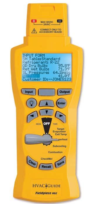
5 Fill in the INPUT FORM Read the OUTPUT FORM Figure 1. INPUT FORM for the Superheat test. The INPUT FORM lists parameters in the order of expected entry. Three ways to enter data: 1. Automatic: Attach appropriate head, select appropriate line with the UP/DOWN arrows, press ENTER to start measuring, and press ENTER again to lock in the value. 2. Drop down menu: To change a parameter that has a default, press RIGHT arrow or ENTER, use UP/DOWN arrows to scroll through the dropdown list, and press ENTER again. 3. Manual: Enter system data (or to enter test data not taken with an accessory head) by pressing the RIGHT arrow and then, character-by-character, use the UP/DOWN arrows and the RIGHT arrow to type in the value. When finished, press ENTER. Figure 2. OUTPUT FORM for the Superheat test. To display the OUTPUT FORM, fill in the INPUT FORM correctly and press the OUTPUT button or scroll down. If the INPUT FORM is missing inputs, the appropriate lines on the OUTPUT FORM will be blank. If the data entered on the INPUT FORM is out of range or physically impossible, an error message is displayed. The OUTPUT FORM displays the results of the calculations. The See Sec: at the bottom of the OUTPUT FORM tells you what section in the manual has more information about how to perform the specific test and what the results mean. To ensure that your changes have optimized the system, retest after the system is stabilized. The CheckMe! test (model HG2) has a more detailed OUTPUT FORM. If everything on the INPUT FORM is filled out properly, the CheckMe! OUTPUT FORM will rank the possible problems in order of likelihood and describe how to fix them. If you haven t taken all the necessary measurements, the first line will tell you what you need to do for a complete diagnosis. 8


6 What Accessory Heads Do I Need? How to Connect Accessory Heads Refer to the chart below to find the recommended accessory head and thermocouple for each measurement. Automatically input measurements with Fieldpiece accessory heads for maximum accuracy and speed, or manually input from Fieldpiece standalone instruments, or non-fieldpiece test equipment. AOX2 ASX14 ACH4 (model HG2) ACM3 ATH4 on HVAC Guide Analyzer OD Dry Bulb Cond Amps 10


7 Tests 1.1 Target Evaporator Exit Temperature Dry Bulb T/C Supply Plenum For given return plenum air conditions, Target Evaporator Exit Temperature gives you an indication of the proper indoor airflow. This test can be easily performed simultaneously with superheat or subcooling tests. Direction of Airflow Fan If actual evaporator exit temperature is more than 3 F above or below the Target Evaporator Exit Temperature, an airflow problem may exist. Ensure that filters are clear, dampers are adjusted properly and the fan speed is set correctly if it can be varied. The Target Evaporator Exit Temperature switch position uses the table from California Title 24. Dry Bulb and Wet Bulb T/C A-Coil Filter Figure 3. Setting up the ATH4 and HVAC Guide analyzer to measure return dry bulb and wet bulb temperatures between the air filter and evaporator coil. 12
8 1.2 Target Evaporator Exit Temperature INPUT FORM 1.3 Target Evaporator Exit Temperature OUTPUT FORM Can be measured automatically with Fieldpiece accessory heads. Customer ID is useful for record keeping. Units can be changed to either English or Metric. If Target and Actual are more than 3 F apart, a modification is needed. Diagnostic text and sections of manual with more information about this test. Figure 4. INPUT FORM for Target Evaporator Exit Temperature. Into Evap Return Dry Bulb and Wet Bulb: Take measurements as close to the inlet of the air handler as possible. If the filter is just before the air handler, the easiest way is to clip an ATWB1 and ATA1 to the filter on the side facing the evaporator and take the measurements. If the filter is not before the evaporator, make small holes in the return plenum just big enough for the probes. Seal any holes before leaving the jobsite. Out of Evap Supply DB (dry bulb temp leaving the evaporator): Measure in the center of the supply plenum. Punch a small hole in the supply plenum and insert a calibrated dry bulb thermocouple such as the ATA1 or ATB1. Make sure the thermocouple is in the center of the plenum cross-section. Seal the hole when finished. An Actual Evap Exit DB Temp below the Target Evap Exit DB Temp indicates low airflow. Increasing airflow can be accomplished by eliminating restrictions in the duct system, increasing blower speed, cleaning filters or opening registers. After corrective measures are taken, repeat measurement procedures as often as necessary to establish adequate airflow range. Allow system to stabilize for 15 minutes before repeating measurement procedure. 1 Figure 5. OUTPUT FORM for Target Evaporator Exit Temperature. Press OUTPUT for the Target Evaporator Exit Temperature OUTPUT FORM. Target Evap Exit DB Temp (Target Evaporator Exit Dry Bulb Temperature): This is the target exit temperature based on the measured indoor conditions. Actual Evap Exit DB Temp (Actual Evaporator Exit Dry Bulb Temperature): This is the measured temperature of the air in the supply. The Actual Evap Exit DB Temp should be within ±3 F of the Target Evap Exit DB Temp. If the temperature is outside of this range, the technician should make modifications to correct the problem. An Actual Evap Exit DB Temp above the Target Evap Exit DB Temp usually indicates low capacity. Occasionally airflow is higher than expected. Look for causes of low capacity such as refrigerant mischarge or dirty condenser coil. If the airflow is high, correct by lowering the fan speed. Because everything within the system is interdependent, one adjustment can affect other parts of the system. For example, increasing airflow increases the superheat, which may require adding refrigerant. After modifications, allow 15 minutes to stabilize; and then retest Residential ACM Manual, Page RD-5, (#5-7) 14

9 2.1 Superheat 2 Superheat is the temperature rise above the boiling point of the refrigerant after the evaporator. Too high, and the refrigerant boils off early in the evaporator and wastes most of the capacity of the evaporator. Too low, and you risk liquid going into the compressor. Using superheat is the best way to obtain proper refrigerant charge for a fixed restrictor metering device system. If the air conditioner is in good working order and the airflow is adjusted properly, comparing the actual and target superheat will tell you if refrigerant needs to be added or recovered. Ensure the pressure never exceeds the manufacturer's maximum overload pressure guidelines. On a fixed restrictor system, the target superheat is determined based upon the indoor wet bulb and outdoor dry bulb temperatures. Proper superheat ensures the compressor doesn't flood under a low indoor load and that the maximum efficiency and capacity are maintained. 2 The Superheat test (switch position) will not work correctly with systems using a variable speed compressor. 16 Figure 6. Using the ASX14 Superheat/Subcooling Head to gather suction line temperature and pressure for the HVAC Guide analyzer Superheat Test.
10 2.2 Superheat INPUT FORM Figure 7. INPUT FORM for Standard Table Superheat Test. Figure 8. INPUT FORM for Custom Table Superheat Test. Standard table uses the Title 24 target superheat table. Can be measured automatically with Fieldpiece accessory heads. Customer ID is useful for record keeping. Custom table allows you to enter your own target superheat value. Can be measured automatically with Fieldpiece accessory heads. Units can be changed to either English or Metric. SH Table: Default: Standard uses the target superheat table from Title 24 for fixed restrictor systems. Other selection: Custom allows you to enter your own target superheat by displaying the Target SH input. Target SH (Custom SH Table): Change the SH Table to Custom and enter the manufacturer s recommended superheat in the Target SH input. Refrigerant: Default: R-22. Other selections: R-410A, R-134A, R-404A, R-407C, R-409A, R-408A, R-507A, R-414B (Hotshot TM ), R-422C (Oneshot TM ), R-422B (NU222B TM ) or R-12. ID Wet Bulb (indoor wet bulb, Standard SH Table): Take measurements very close or within the return air side of the inlet to the air handler (not at the return grill since temperatures change by the time the air reaches the indoor coil). Wet the wet bulb sensor (ATWB1) and insert it after 15 minutes of continuous running. Clip downstream of the filter if the filter is just before the air handler. Clip on the side facing the evaporator and take the measurements. If the filter is not before the evaporator, make small holes in the return plenum just big enough for the probes. Seal any holes before leaving the jobsite. Watch the wet bulb temperature; it will drop and then stabilize. The wet bulb temperature is the stabilized reading. If the sensor starts to dry out, the reading will rise and the wrong temperature will be recorded. SL Pressure (suction line pressure): Connect the ASX14 to the suction side service port. Select pressure mode on the ASX14 head. The system must be stabilized before taking the measurements. Enter data manually if you want to get pressure from your gauges. The analysis is only as good as the measurements. The Fieldpiece ASX14 has better resolution than most gauge sets. SL Temp (suction line temperature): Measure near SL service port (within 6 inches). Use the ATC1, ATC2 or ATC3 to get a good pipe temperature. The clamp should be perpendicular to the pipe and should be securely seated with the sensor in contact with the suction line. If working on a package unit make sure you are at least 6 inches away from the compressor. OD Dry Bulb (outdoor dry bulb, Standard SH Table): Clip a calibrated ATA1 to the inlet of the condenser fins (typically on the side of the condenser), in the shade if possible. Note that the temperature of the air entering the outdoor coil can be considerably different than the ambient temperature due to recirculation of air exiting the unit. Determine the average temperature of the air entering the condenser. Figure 9. ATC1 pipe clamp thermocouple attached to a pipe correctly. 18
11 2.3 Superheat OUTPUT FORM Figure 10. Superheat Test OUTPUT FORM. If Target SH and Actual SH are more than 5 F apart, as in this example, you need to make adjustments to the system. Boiling point is used to calculate Superheat. Diagnostic text and sections of manual with more information about this test. Press OUTPUT for the Superheat OUTPUT FORM. Target SH (Superheat): Indicates what the superheat should be as calculated from outdoor dry bulb and indoor wet bulb Actual SH (Superheat): Shows the superheat calculated from the measured suction line temperature and suction line pressure. Vapor Sat: This is the saturation temperature of the refrigerant in the evaporator coil. This is the temperature a refrigerant will boil at a given pressure. It is one of the temperatures from which superheat is calculated. The Actual SH (superheat) should be within ±5 F of the Target SH to ensure optimum performance. If the actual SH is outside this range, modifications to the charge or adjustments to the restrictor (TXV) are necessary. Adding refrigerant lowers your Actual SH. Recovering refrigerant increases your Actual SH. The amount of refrigerant necessary to add or recover will vary based on the size of the system and the difference between the Actual and Target SH. Because everything within the system is interdependent, one adjustment can affect other parts of the system. For example, increasing airflow increases the superheat, which may require adding refrigerant. After modifications, allow 15 minutes to stabilize and then retest. Superheat and Subcooling FAQ Q: How do superheat/subcooling tools work? A: Superheat tools measure suction line pressure and suction line temperature, and calculate the actual superheat. Subcooling tools measure the liquid line pressure and liquid line temperature and calculate actual subcooling. The refrigerant charts for calculations are incorporated into the software of the HVAC Guide analyzer. Q: When should I take my actual and target superheat/subcooling? A: Superheat and subcooling readings must be taken when the system is in a steady state. Typically a residential system will be in a steady state after minutes. Turn the system on and set the thermostat low to ensure that the system doesn t turn off during your testing. Once the system s temperatures and pressures are not fluctuating, the system is in a steady state. Wet bulb temperature, outdoor dry bulb, suction line pressure and suction line temperature must be taken within a short time period to ensure valid results. Conditions that affect your target superheat and target subcooling can change by the minute. Q: What do I do with my ACTUAL superheat or ACTUAL subcooling measurements? A: Compare actual readings against the target superheat/ subcooling. As a general rule, if superheat is too high, add refrigerant. If too low, remove refrigerant. If subcooling is too low, remove refrigerant. If subcooling is too high, add refrigerant. Consult the manufacturer s specifications before adding or recovering refrigerant as further diagnostic tests may be needed Continued on page 27 20
12 3.1 Subcooling 3 Subcooling is the temperature decrease below the boiling point (same as the condensing point) in the condenser. Too high, and refrigerant condenses too early in the condenser and wastes most of the capacity of the condenser. Too low, and a mixture of gas and liquid can be delivered to the expansion valve, reducing efficiency. Subcooling is the best way to obtain proper refrigerant charge for a TXV/EXV system. If the air conditioner is in good working order and the airflow is adjusted properly, comparing the actual and target subcooling will tell you if refrigerant needs to be added or recovered (ensure the pressure never exceeds the manufacturer's maximum overload pressure guidelines). In a properly working TXV/EXV system, the superheat is held constant. Ensure the TXV/EXV bulb is installed properly, there is proper refrigerant to obtain target subcooling, and there are no liquid line restrictions. Adjust refrigerant charge so that the actual subcooling is within ±3 F of target subcooling. 3 The Subcooling test (switch position) will not work correctly with systems using a variable speed compressor. 22 Figure 11. Using the ASX14 Superheat/Subcooling Head to gather liquid line temperature and pressure for the HVAC Guide analyzer Subcooling Test.

13 3.2 Subcooling INPUT FORM Figure 12. Subcooling Test INPUT FORM question. Answering Yes or No takes you to a different INPUT FORM. Always use the manufacturer's recommended subcooling when available. Target SC must be entered from the equipment specifications. Can be measured automatically with Fieldpiece accessory heads. Units can be changed to either English or Metric. Figure 13. Subcooling Test INPUT FORM with Manufacturer's Data. Target SC (WITH Manufacturer s Data): Manually input the manufacturer s target subcooling. LL Pressure (liquid line pressure): Connect the ASX14 to the liquid line service port. Set the accessory head to measure pressure and ensure the reading stabilizes before locking in the reading. Enter data manually if you want to get pressure from your gauges. The analysis is only as good as the measurements. The Fieldpiece ASX14 has better resolution than most gauge sets. LL Temp (liquid line temperature): Measure near the same location LL Pressure was taken. Use the ATC1, ATC2 or ATC3 to get a good pipe temperature. The clamp should be perpendicular to the pipe and should be securely seated with the sensor in contact with the liquid line. If working on a package unit make sure you are at least 6 inches away from the compressor. Without manufacturer's recommended subcooling data, the HVAC Guide analyzer makes a conservative Target SC estimate. Can be measured automatically with Fieldpiece accessory heads. Current time is set within TIME switch position (see page 50). Figure 14. Subcooling Test INPUT FORM without Manufacturer's Data. Does the manufacturer have a recommended subcooling? Default: Yes. Always answer "YES" if you have a manufacturer s recommended subcooling. Other selection: "NO" will use a conservative estimate for Target SC (Subcooling). Refrigerant: Default: R-22. Other selections: R410A, R-134A, R-404A, R-407C, R-409A, R-408A, R-507A, R-414B (Hotshot TM ), R-422C (Oneshot TM ), R-422B (NU222B TM ) or R-12. Figure 15. ATC1 pipe clamp thermocouple attached to a pipe correctly. 24
14 3.3 Subcooling OUTPUT FORM Figure 16. Subcooling Test OUTPUT FORM. If Target SC and Actual SC are more than 3 F apart, as in this example, you need to make adjustments to the system. Boiling point is used to calculate Subcooling. Diagnostic text and sections of manual with more information about this test. Press OUTPUT for the Subcooling OUTPUT FORM. Target SC (Subcooling): Indicates what the subcooling should be from the manufacturer s specifications. The HVAC Guide analyzer uses a built in conservative estimate when manufacturer s specifications are not available. Actual SC (Subcooling): Displays the subcooling calculated from the measured liquid line temperature and liquid line pressure. Liquid Sat: This is the saturation temperature of the refrigerant in the condenser coil. It is one of the temperatures from which subcooling is calculated. The Actual SC (subcooling) should be within ±3 F of the Target SC for correct refrigerant charge. Temperatures outside of this range indicate that you need to make adjustments. Adding refrigerant increases your Actual SC. Recovering refrigerant decreases your Actual SC. The amount of refrigerant necessary to add or recover will vary based on the size of the system and the difference between the Actual and Target SC. Because everything is interdependent, changes in one part of the system affect other parts of the system. For example, increasing airflow decreases the subcooling, which may require adding refrigerant. After modifications, allow 15 minutes for the system to stabilize; and then retest. Superheat and Subcooling FAQ Part 2 (continued from page 21) Q: What if my ACTUALS are far different from my TARGETS, but the system seems to be running properly? A: Many poor performing systems have actual superheat/subcooling measurements well outside the target. The system may be drastically overcharged or undercharged. Comparing actual superheat/subcooling readings with the manufacturer s equipment specific target superheat/subcooling often confirms the system s condition. Sometimes there is something else wrong. Make sure the system has been in operation for at least 15 minutes and is stable. Make sure it continues to operate throughout the test. Take your readings in as short of a time period as possible. Things can change, even for a system that appears stable. Make sure your test equipment is calibrated. Refer to the manual of the accessory head for calibration instructions. Make certain the unit selected corresponds to the reading you are taking. For superheat on accessory heads (ASX14, ASX24), make certain the large switch on the face of the head is switched to superheat and small switch is in the SH position. Make certain that you are testing for superheat/subcooling at the proper location in the system. Test the evaporator/suction line side of the system for superheat. Test the condenser/high side of the system for subcooling. If you still get readings that don t seem right, you can perform a manual test using your gauges, a wet sock for wet bulb (ATWB1 wet bulb thermocouple), thermometer, refrigerant chart, and manufacturer s target superheat chart. If it still appears your unit is reading superheat/subcooling incorrectly, call Fieldpiece technical support. Q: Where can I find more info on Superheat and Subcooling? A: Visit 26


15 4.1 Combustion Combustion Test helps you determine the effectiveness of the combustion by analysis of combustion products and temperature. The Combustion Test will only tell you about combustion and does not take into account any losses from poor insulation, or cycling and standby losses. It does not measure any losses in the distribution system such as uninsulated hydronic piping, air duct leakage or insulation levels. Properly tuned gas combustion equipment will produce little or no carbon monoxide, no soot, and will consume less fuel. Supply Plenum Flue Figure 17. CO measurement of flue gas for the Combustion Test using an ACM3 Carbon Monoxide Head and the AOXP2 pump that s included with the AOX2 Combustion Check Head. 28
16 4.2 Combustion INPUT FORM Overview 4.3 Combustion OUTPUT FORM Overview Figure 18. Combustion Test INPUT FORM. Select the Fuel and what type of equipment you are working on. Can be measured automatically with Fieldpiece accessory heads. Customer ID is useful for record keeping. Combustion gases should be sampled close to the exit from the heat exchanger within an area where all gasses would be well mixed and before dilution air enters the venting systems (i.e. draft hoods, barometric dampers, etc). Testing within 18 inches of the breech is a typical location for most oil-fired equipment. If the appliance is an atmospheric gas with a draft hood, the test would be taken in the top flue passage prior to mixing with dilution air. After testing is complete, the hole in the flue/stack must be patched with temperature silicone or a comparable plug. Fuel: Select Natural Gas, Oil #2 or Propane for the fuel type of the system or appliance. Type: Default: Condensing. Other selection: Non-Condensing. The presence of a condensate line indicates a condensing unit, otherwise it is a non-condensing unit. O 2 : Connect the AOX2 with the switch on %O 2 and take a sample of the combustion products in the flue/stack (within 18 inches from the start of the flue). Flue Temp: Connect the ATR1 temperature probe to the AOX2. Set the AOX2 on TEMP and measure the temperature of the combustion products in the flue/ stack (18 inches from the start of the flue). CO: Connect the ACM3 and take a sample of the combustion products in the flue/stack in the same location as the O2% measurement (within 18" from the start of the flue). Primary Temp: Measure the temperature of the air being introduced to the combustion process. Measure the air temperature as close as possible to the entry point of the appliance. Figure 19. Combustion Test OUTPUT FORM. Modify combustion equipment to bring these calculations to the manufacturer's specifications. Diagnostic text and sections of manual with more information about this test. Press OUTPUT for the Combustion OUTPUT FORM. CO 2 : The %CO 2 in the combustion products. Excess O 2 : The amount of O 2 above the minimum theoretical amount needed for complete combustion. For complete and efficient combustion, excess O 2 must be adjusted to manufacturer s specifications. COAF (carbon monoxide air free): The amount of CO in the combustion products taking into account the dilution effect of excess O 2. Net Temp: The stack (vent) temperature minus the primary air temperature. Standard Eff (Efficiency): The actual efficiency of the combustion equipment calculated by analyzing the losses up the exhaust. Siegert Eff (Efficiency): The European standard for combustion efficiency. 30
 should be below 400PPM in the flue.")
 6-9% Stack Temperature 325-500 F Condensing Natural Gas or LPG Oxygen (O2) 6-9% Stack Temperature 90-140 F Natural Gas/LPG Power Burners Oxygen")
17 The following tables show acceptable results from the Combustion Test for different types of equipment 4. For all combustion equipment, ANSI Manufacturing Standards recommends carbon monoxide (CO) should be below 400PPM in the flue. Technical Standards and Safety Authority recommends repair above 100PPM in the flue. Atmospheric Fan Assisted Natural Gas or LPG Oxygen (O2) 6-9% Stack Temperature F Condensing Natural Gas or LPG Oxygen (O2) 6-9% Stack Temperature F Natural Gas/LPG Power Burners Oxygen (O2) 3-6% Stack Temperature F Fuel Oil Flame Retention Power Burners Oxygen (O2) 3-7% Stack Temperature F Fuel Oil Non-Flame Retention Power Burners Oxygen (O2) 6-9% Stack Temperature F Condensing Oil Oxygen (O2) 3-7% Stack Temperature F Erik Rasmussen Erik Rasmussen has been an expert in the combustion analysis field for over 20 years. Rasmussen has helped Fieldpiece in providing many of the tables and much of the content of the combustion section in this manual to reflect the best real-world practices and knowledge of today. Rasmussen has also authored and co-authored several books on combustion analysis which go into much greater depth on the fundamentals of the operation and diagnosis of combustion equipment. Sixteen 16 years as a service and installation specialist of: * Natural gas * Propane * Oil heat * Air conditioning Contractor HVACR Instructor Co-author, "Carbon Monoxide: A Clear and Present Danger", ESCO Press Author, Combustion Analysis and Fuel Efficiency, ESCO Press International Programs Director for COSA, the Carbon Monoxide Safety Association Board Member HVAC Excellence President of ESCO press international, (Canada) 4 From Carbon Monoxide a Clear and Present Danger Third Edition, Dwyer, Leatherman, Manclark, Kimball, Rasmussen, ESCO Press Rasmussen continues to stay current on all technologies and procedures through the operation of his own service organization.

18 5.1 CheckMe! 5 6 The CheckMe! test is included on model HG2. It is available for purchase on model HG1. CheckMe! is the most advanced real-world method for troubleshooting A/C systems. It looks at the big picture to diagnose problems. Superheat, Subcooling, and Target Evaporator Exit Temperature tests look at individual performance indicators to determine if they are within proper range. CheckMe! looks at the system as a whole to give a more complete diagnosis. CheckMe! saves time and money by quickly diagnosing a range of potential problems or even multiple problems. CheckMe! recommends actions to tune the air conditioner or heat pump to its optimum with minimal retests. This leads to even fewer call backs. The algorithms built into CheckMe! are based on the real world servicing of over 250,000 air conditioners. The testing procedure and accuracy of the diagnosis have been refined over many years by Proctor Engineering. The CheckMe! switch position is a real time-saver because it can give you a more accurate diagnosis than looking at individual aspects of the air conditioner. The CheckMe! position has diagnoses that will help you pinpoint problems with the system. Besides providing better diagnoses, it also checks the test numbers and warns you if there is a likely testing error. In these cases, you will want to retake some measurements. CheckMe! in the HG2 will analyze with almost any amount of data. The more information supplied, the more accurate and comprehensive the diagnoses. CheckMe! determines the current state of the equipment. It is recommended that you pretest before repairs and posttest to confirm the improvement. 5.2 CheckMe! INPUT FORM Overview Figure 20. CheckMe! INPUT FORM. General Information: The type of system and the nominal tonnage. Can be measured automatically with Fieldpiece accessory heads. Model HG2 can measure AC amps automatically with Fieldpiece accessories ACH4 or ACDC6. True Flow: The measurements are only visible if you select Yes for True Flow. These are manual inputs. Grant: These are all manual inputs which are used for record keeping when participating in a grant program or third party verification. Units can be changed to either English or Metric. For full documentation, pretest before any changes are made. Clean the coils and filters prior to the initial test to faster achieve an optimized system. The outside coil must be dry for accurate diagnoses. Completely fill out the CheckMe! INPUT FORM for more comprehensive and accurate diagnoses. 5 CheckMe! is the registered trademark of Proctor Engineering Group, Ltd. 6 The CheckMe! test (switch position) will not work correctly with systems using a variable speed compressor. 34
19 CheckMe! INPUT FORM Sys Type (System Type): Default: AC (Air Conditioning). Other selections: H Pump Heat (heat pump in heating mode), H Pump Cool (heat pump in cooling mode) or Geothermal. Grant and Sys Info:Default: None. Other selections: New, None or a previously created Grant. Unless you are working under a Grant program, usually through a utility or government, then the Grant will remain as None. If you are using this for a grant proceed to the GRANT section of this manual for more details. INDOOR UNIT All temperature and pressure measurements must be taken after the unit reaches steady state (generally 15 minutes of continuous operation). Metering Device: Default: TXV/EXV. Other selection: Fixed. Return DB (dry bulb) and Return WB (wet bulb):take measurements very close to or within the return air side of the air handler (not at the return grill since temperatures change by the time the air reaches the indoor coil). Wet the wet bulb sensor (ATWB1) and insert it after 15 minutes of continuous running. Insert the dry bulb sensor (ATA1) through the same hole. They can be clipped together on the downstream side of the filter if the filter is just before the air handler. Watch the wet bulb temperature; it will drop and then stabilize. The wet bulb temperature is the stabilized reading. If the sensor starts to dry out, the reading will rise and the wrong temperature will be recorded. If the filter is not directly upstream of the air handler, make small holes in the return plenum just big enough for the probes. Seal any holes before leaving the jobsite. Supply DB (dry bulb leaving the indoor coil): Measure in the center of the supply plenum. Make a small hole in the supply plenum and insert a calibrated dry bulb thermocouple such as the ATA1 or ATB1. Determine the average air temperature in the supply plenum. OUTDOOR UNIT Refrigerant: Default: R-22. Other selection: R410A. Rated Amps (rated amperage of the outside unit): This can be found on the nameplate along with the outdoor voltage and the refrigerant. Target Subcool: Manufacturer s recommended subcooling for TXV/EXV systems. This varies by manufacturer, and may also change depending on weather conditions. Always charge to the equipment manufacturer s specifications when available. If no target subcooling is available then the HVAC Guide analyzer will make a conservative estimate. SL Pressure (suction line pressure): Connect the ASX14 to the suction side service port. Select pressure mode on the ASX14 head. The system must be stabilized before taking the measurements. Enter data manually if you want to get pressure from your gauges. The analysis is only as good as the measurements. The Fieldpiece ASX14 has better resolution than most gauge sets. SL Temp (suction line temperature): Measure near SL service port (within 6 inches). Use the ATC1, ATC2 or ATC3 to get a good pipe temperature. The clamp should be perpendicular to the pipe and should be securely seated with the sensor in contact with the suction line. On a package unit make sure you are at least 6 inches away from the compressor and not on the hot gas discharge line. 36
20 LL Pressure (liquid line pressure): Connect the ASX14 to the liquid line service port. Set the accessory head to measure pressure and ensure the reading stabilizes before locking in the reading. Enter data manually if you want to get pressure from your gauges. The analysis is only as good as the measurements. The Fieldpiece ASX14 has better resolution than most gauge sets. Sup Plen Pres: TrueFlow system operating pressure with the filter installed and no TrueFlow grid. This is the normal supply operating pressure (NSOP) and is measured using the static pressure probe included with the TrueFlow plate. Flow Pressure: This is the TFSOP and is measured using the TrueFlow plate. LL Temp (liquid line temperature): Measure near the same location that the LL Pressure was taken. Use the ATC1, ATC2 or ATC3 to get a good pipe temperature. The clamp should be perpendicular to the pipe and should be securely seated with the sensor in contact with the liquid line. OD Dry Bulb (outdoor dry bulb temperature): Clip a calibrated ATA1 to the inlet of the condenser (typically on the side of the condenser), in the shade if possible. Note that the temperature of the air entering the outdoor coil can be considerably different than the ambient temperature due to recirculation of air exiting the unit. Determine the average temperature of the air entering the condenser. Cond Amps Draw (actual condensing unit amp draw): For a package system this is the total amp draw of the unit. With a factory HG2, use an ACH4 amp clamp and take measurement automatically. To use another amp clamp (such as the SC77) and for HG1s upgraded to an HG2, input this measurement manually. TrueFlow 7 The TrueFlow meter measures the airflow directly via a grid installed in place of the filter (or other location that has all the indoor unit airflow through it). For more information please visit TrueFlow : Default: NO. If NO, skip ahead to the Customer ID. Answering YES unlocks the inputs for this section. Nom Ton: Nominal tonnage of the A/C system. Grid Size: Default: 14 inches. Other selection: 20 inches. Choose the grid size you are using. 7 TrueFlow is the registered trademark of The Energy Conservatory. 38 Sup Plen Pressure with Grid: TrueFlow system operating pressure with the filter and the TrueFlow grid installed. This is the TF SOP and is measured using the static pressure probe included with the TrueFlow plate. GRANT FORM If you are working under a grant you are typically required to track additional information about the system in order to qualify for the tax rebates or other incentives. In parts of the Unites States, CheckMe! is used to verify that a system is tuned to the highest standards and qualify the work for grants. Air conditioning comprises a significant portion of power consumption in the United States but more importantly is often the cause of peak power usage periods. Grants are often funded by utilities or government agencies in order to reduce the peak electrical power consumption and power infrastructure needed to support that. In order to participate in these grants, a technician will usually have to work through a third party verifier. Contact your local utility to learn on how to become a grant participant. After you have selected "New" or a pre-existing grant from the list of grants you will be taken to the GRANT FORM. The Grant form allows you to create new grants in accordance with particular specifications. Grant and Sys Info: Use alpha-numeric characters to manually input and name this grant. Once created you can access this grant for future tests. Optional Inputs: Optional inputs are inputs that you want to be present on the INPUT FORM for the
, Furnace Model No.")
21 new grant you have created. These inputs are simply for bookkeeping and are not used for any diagnosis or performance calculations. By turning these to "Yes" you will see them on the INPUT FORM when this grant is selected. List of inputs: Indoor Model No. (number), Furnace Model No. (number), ID VOLTS (voltage of indoor unit), ID Full Ld Amps (full load running amperage of indoor unit), Sup Plen Press (supply plenum pressure, static), Ret Plen Press (return plenum pressure, static), Evap Fan Amp (evaporator Fan amperage), Test (initial or after repair), Outdoor Model No (number), Outdoor Year (year manufactured of the outdoor unit), Outdoor Serial No (serial number of the outdoor unit), OD Volts (voltage of the outdoor unit). Advanced Tolerances: These are some of the basic error tolerances which the CheckMe! program uses to determine if a system is performing properly. Some grants have different tolerences on parameters such as superheat and airflow. This is where you can adjust the tolerances. By adjusting these numbers you will change the way systems are evaluated by the CheckMe! for this particular grant. The superheat and subcooling tolerances are: Initial SH Tol (superheat tolerance for initial test), After SH Tol (superheat tolerance for test after repair), Initial SC Tol (subcooling tolerance for initial test), After SC Tol (subcooling tolerance for test after repair). These tolerances apply only when the optional input "Test" is yes. The airflow tolerances are: Temp SPLIT Tol (maximum allowable difference between target temperature split and actual temperature split), Aflow Min (minimum allowable airflow before a unit is considered to have low airflow) and Aflow Max (maximum allowable airflow before a unit is considered to have high airflow). Press the SAVE button to save your changes and return to the CheckMe! INPUT FORM. 5.3 CheckMe! OUTPUT FORM Overview Figure 21. CheckMe! OUTPUT FORM. Press the OUTPUT for the CheckMe! OUTPUT FORM. The diagnoses and recommendations are listed in order with the most likely diagnosis first. Because all parts of an A/C system are interdependent, changes made to one part of the system can influence other parts of the system. For example, increasing airflow may increase the superheat, which may require adding refrigerant. To be efficient, continually check the superheat and/or subcooling as you make refrigerant charge adjustments. After modifications, allow 15 minutes to stabilize before your final test. 5.4 Indoor Coil Airflow Diagnostic text and sections of manual with more information about this test are displayed in order of likelihood. Low airflow across the inside coil is one of the most common problems and should be corrected before final decisions are made about refrigerant charge and many other issues. Airflows in most climates should usually be between 350 to 400 cfm per ton. Airflows in Dry climates are limited by the rapidly increasing watt draw of the fan motor at higher airflows. 40
22 5.401 Airflow OK: The indoor coil airflow was directly measured using the TrueFlow grid and is OK Probable OK airflow: The indoor coil airflow was tested by an indirect means (temperature split) and is probably OK Airflow unknown, check airflow: The measurements are insufficient to diagnose the indoor coil airflow. Either measure the Return Plenum Dry Bulb, Wet Bulb and Supply Plenum Dry Bulb or use a True- Flow Plate Low airflow, increase airflow until actual temp split matches target temp split. Actual temp split is F and target temp split F: The indoor coil airflow is low based on the temperature split. Check the filter and coil, inspect for any restrictions and blockages. Make sure all registers are open. If the airflow remains low, consider increased blower speed and duct system modifications. Supply and return plenum static pressures can be used to diagnose the causes of low airflow Low airflow, increase airflow: The indoor coil airflow was directly measured using the True- Flow grid and is low. Check the filter and coil, inspect for any restrictions and blockages. Make sure all registers are open. If the airflow remains low after a retest, consider increased blower speed and duct system modifications. Supply and return plenum static pressures can be used to diagnose the causes of low airflow Low capacity or possible high airflow, measure airflow directly: The temperature split is low. This usually means that the capacity of the system has been reduced due to incorrect refrigerant charge. Higher than expected airflow is rare, but does occur occasionally. Measuring the airflow directly would identify if high airflow is the cause of the low temperature split High airflow, possibly reduce airflow: The indoor coil airflow was directly measured using the TrueFlow grid and is higher than expected. Consider reducing the airflow particularly if the unit is in a damp climate. In heat pumps high airflow causes uncomfortably low delivery temperatures Possible plenum temperature measurement error, retake plenum temperatures: The reported wet and dry bulb temperature readings from the return and supply plenums are unlikely. Retake the measurements in the INPUT FORM. See Return DB and Return WB sections for detailed instructions on how to take these measurements properly. 5.5 Refrigerant Charge Incorrect refrigerant charge is the most common mechanical problem with air conditioners and heat pumps. There are widespread poor practices and misinformation regarding refrigerant levels. The primary method for correctly adjusting the charge for Fixed (non-txv) metering devices systems is superheat. The actual superheat needs to be matched to the target superheat, which changes with indoor and outdoor conditions. The optimum refrigerant charge as indicated by superheat is influenced by the airflow across both the indoor and outdoor coils. Repair any airflow problems before setting the final refrigerant charge. The primary method for correctly adjusting the charge for TXV or EXV systems is subcooling. The actual subcooling needs to be matched to the target subcooling. The target subcooling is usually on the manufacturer's nameplate along with the model and serial numbers (also in the installation manual for the equipment). For heat pumps, it is best to set the refrigerant levels in the summer in the cooling mode. The HG2 can also check the capacity of heat pumps in the winter which is an indicator of correct refrigerant charge but will not provide as accurate or thorough a diagnosis as checking the heat pump in cooling mode during the warmer months. 42
23 5.501 Charge OK: Refrigerant charge was tested using the appropriate method, and it is OK Possible OK charge: The primary indicator of refrigerant charge (subcooling for TXV/EXV or superheat for non-txv) indicates the refrigerant level was OK. However, a secondary indicator reduces the confidence in that diagnosis. Check out any other potential problems indicated Charge unknown, check charge: The measurements are insufficient to diagnose the refrigerant charge. For best results return to the INPUT FORM by pressing the INPUT button and fill out the INPUT FORM completely before pressing the OUTPUT button again Possible undercharge, possibly add refrigerant: Try fixing other conditions first and retesting but if this diagnosis persists the system may be undercharged, if no other conditions are triggered, consider adding refrigerant to correct. The amount of refrigerant to add will vary based on the size of the system and the difference between Target and Actual superheat/subcooling Undercharged, add refrigerant until actual superheat reaches target superheat. Your actual superheat is F and your target superheat is F: This fixed metering device system is low on refrigerant. Add refrigerant until the actual superheat is within ±5 F (Grant = None) of the target superheat. The closer the actual superheat is to the target superheat, the better Undercharged, add refrigerant to obtain 6 F of superheat: This fixed metering device system is low on refrigerant. Since the test conditions are hot outside, dry inside, or both, the exact target superheat cannot be determined. Because the actual superheat is greater than 6 F the unit is undercharged. Add refrigerant until the superheat is 6 F Charge unknown, raise indoor temperature to obtain a target superheat 5 F and retest: Since the test conditions are hot outside, dry inside, or both, the exact target superheat cannot be determined. This fixed metering device system may be correctly charged or overcharged. It may be possible to open windows or run the furnace to change the indoor conditions enough to obtain a target superheat upon a retest Possible overcharge, possibly remove refrigerant: Try fixing other conditions first and retesting, but if this diagnosis persists, the system may be overcharged. If no other conditions are triggered, consider recovering refrigerant to correct. The amount of refrigerant to recover will vary based on the size of the system and the difference between Target and Actual superheat/subcooling Overcharged, recover refrigerant until actual superheat reaches target superheat. Your actual superheat is _ F and your target superheat is _ F: There is too much refrigerant in this non-txv system. Remove refrigerant until the superheat is within ±5 F of the target superheat. The closer the superheat is to the target, the better Overcharged, recover refrigerant until actual subcooling reaches target subcooling. Actual subcooling is _ F and target subcooling is _ F: There is too much refrigerant in this TXV/EXV system. Remove refrigerant until the actual subcooling is within ±3 F (Grant = None) of the target subcooling. The closer the actual subcooling is to the target subcooling, the better Undercharged, add refrigerant until actual subcooling reaches target subcooling. Your actual subcooling is _ F and your target subcooling is _ F: This TXV/EXV system is low on refrigerant. Add refrigerant until the subcooling is within ±3 F (Grant = None) of the target subcooling. The closer the actual subcooling is to the target subcooling, the better. 44
24 5.6 Refrigerant Lines and Metering Devices Refrigerant line restrictions, incorrect orifice sizes, and TXVs improperly installed are not uncommon. Any of these problems can lead to premature compressor failure. If there are restrictions in the refrigerant lines (pinches, dirty filter driers), the charge measurements will provide contradictory information; and getting proper performance will not be possible. Similarly if the orifice of the metering device is too small or partially blocked by foreign material in the refrigerant (such as chips and flakes from improper brazing techniques), the unit will not perform to specifications. If a fixed orifice is too large (not matched to the inside coil), the refrigerant will not meter properly, contradictory measurements will be obtained, and performance will suffer. A thermostatic expansion valve (TXV) only works when the sensing bulb is in solid contact with the suction line and only senses the temperature of the suction line. Therefore, it must be well insulated from surrounding air. The TXV is designed to maintain a constant superheat Possible oversized metering orifice, consult manufacturer s specifications: The metering orifice is suspected of letting too much refrigerant through. Check that the orifice is sized properly. Find the metering device part number and obtain the orifice size from the manufacturer or distributor and verify the size is appropriate for the air conditioner Probable oversized metering orifice, consult manufacturer s specifications: The metering orifice lets too much refrigerant through. Check that the orifice is sized properly. Find the metering device part number and obtain the orifice size from the manufacturer or distributor and verify the size is appropriate for the air conditioner Check TXV to ensure proper functioning: This TXV is not maintaining proper superheat. Check that the TXV bulb is adjusted properly and in continuous contact with the suction line and well -insulated from the surrounding air Possible liquid line restriction, check liquid line: Make sure the service shut-off valves are open. Check the liquid line for kinks, tight bends or sections that may have been stepped on or crushed. Check for a large temperature difference between the liquid line at the compressor and at the metering device. 5.7 Condenser Coil Performance Condenser airflow OK: The condenser airflow and capacity indications are OK Condenser approach unknown, check condenser approach: Liquid line temperature and liquid line pressure measurements need to be taken for the condenser approach. These measurements give indications of the performance of the air conditioner including diagnoses of compressor problems, low capacity, and low condenser airflow Low condenser airflow, clean condenser, check condenser fan: There is insufficient airflow going across the condenser for the needed heat transfer. Check that the condenser coils and fins are clean, aligned and free of nearby obstructions. Check the fan motor bearings to ensure that the fan is rotating freely. 5.8 Outdoor Unit Amp Draw The outdoor unit amp draw gives indications of the health of the compressor as well as overcharge and condenser coil performance Outdoor amp draw OK: The outdoor unit is running at the proper amperage for the current conditions. 46
25 5.802 Condensing unit amps unknown, check condensing unit amps: The outdoor unit amp draw was not measured High outdoor amp draw, probable excessive compressor friction: Check other possible causes of high amp draw (low condenser airflow and refrigerant overcharge) before condemning the compressor. Check that condenser coils and fins are clean, aligned, and free of nearby obstructions Low outdoor amp draw, possible compressor valve or motor problem: Check the refrigerant charge before condemning the compressor. 5.9 Cooling Capacity The heat rejection at the outside unit is another measurement that gives indication of the health of the compressor as well as other potential problems Low capacity: This unit is operating under its expected capacity. Check the refrigerant charge, repair if needed, and retest Low capacity, check compressor amps and coil saturation temperatures: Full diagnosis of this situation requires a complete set of data including compressor amps, high and low side pressures, and liquid and suction line temperatures Heat Pump in Heating Test the refrigerant charge for a heat pump in the summer in the cooling mode if possible for the best result. This procedure checks the heating capacity of the heat pump against the expected capacity for the test conditions. In order to determine the capacity of a heat pump, the airflow through the inside coil must be directly measured with the TrueFlow Heating Capacity OK: The heat pump is delivering the proper heating Capacity unknown, check capacity: The TrueFlow inputs, outdoor unit entering temperature, return plenum temperature, and supply plenum temperature need to be measured before determining capacity Low capacity, defrost outside coil or adjust charge and retest: Verify that the outside coil is not frosted or iced. Frost reduces the capacity of the heat pump. If the unit is not frosted, adjust the refrigerant charge per the manufacturer s specification High temp split, make sure strip heat is NOT on, recheck airflow if necessary: Check amperage to the electric strip heaters to verify they are turned off. 48


26 Advanced Operations Time The internal clock is the basis for the time stamps saved with test data. The time cannot be altered once data is taken; therefore, setting up the time before taking data is important to maintain records in the correct order. The TIME is shown on the bottom of the LCD on most INPUT FORMs. Rotate the dial to the TIME switch position. Press RIGHT arrow to change time if needed. LEFT and RIGHT arrows cycle through month, day, year, military clock, and minutes. UP and DOWN arrows adjusts. Press ENTER to set time. Memory (MEM) From the Memory switch position you can delete a single test, entire customer file or all data or any grants you have created. You can also check your version of firmware to see if you are up to date and your memory status, to see how much memory you have left. You can also communicate with the PC and transfer data to and from with the Com with PC option. See page 56 for more details. Units On every INPUT FORM there is a Units line. The default is English units. Metric units can be used by pressing the RIGHT arrow when Units is highlighted. Scroll Up or DOWN to toggle between English and Metric units. Press ENTER to lock in your selection. The HVAC Guide analyzer will convert any measurements you have taken when units are changed mid test. The units change is universal throughout all switch positions. CUSTOMER ID On every INPUT FORM there is a Customer ID line used for record keeping and long-term customer tracking. Press ENTER when CUSTOMER ID is highlighted to select a previously saved Customer ID. To enter a new (unsaved) Customer ID, press the RIGHT arrow when CUSTOMER ID is highlighted. Now adjust the value character-by-character using the UP/DOWN arrows and the RIGHT arrow. When finished press ENTER to input the new Customer ID. Figure 23. Selecting a previously saved Customer ID. Figure 22. Screenshot of Memory (MEM) switch. 50


27 Clearing a single input or INPUT FORM Press CLEAR when an input is highlighted to erase a single input. Hold the CLEAR button for three seconds and select Yes to clear an entire INPUT FORM. Recalling Saved Tests While in the desired test, press the RECALL button to access previously saved test data. Highlight the Customer ID from the list, and press ENTER, and then highlight the date and time of the test you wish to recall, and press ENTER again. The INPUT FORM for that switch position will then be populated with the previous test s data. No Outputs are saved on the HVAC Guide analyzer, they are simply recalculated from the saved inputs. Figure 24. Deleting the entire INPUT FORM of a Superheat Test. Saving Data Press the SAVE button and press ENTER while Yes is highlighted when in an INPUT FORM to save test data. Test data is saved along with Customer ID and a time stamp. You will be prompted to input a Customer ID before saving. Figure 26. Selecting the Customer ID of the test to Recall. Figure 27. Selecting which test time to Recall. Figure 25. Saving data for Superheat analysis. Contrast Adjustment To adjust the contrast level of the display hold the BACKLIGHT button until the Contrast Adjustment Screen shows. Press UP and DOWN arrows to adjust, and ENTER to set. 52

28 PC Software Installing the PC Software 1. To install the HVAC Guide analyzer software onto your PC, insert the CD into the CD-ROM drive. The installation window should pop-up automatically. If not, manually open the CD contents through "My Computer." 5. Launch the HVAC Guide analyzer software from your Desktop or the Start menu on your PC. 2. Click the grey button next to "Install PC Software," for your operating system. Follow the on-screen instructions. 3. Exit out of the installation screen. Overview: Communicating with a PC 1. Make sure the HVAC Guide analyzer is off. Plug the IR2 USB cable into the bottom of the HVAC Guide analyzer. 2. Plug the USB end of the IR2 USB cable into a USB port of your PC. 3. Turn the dial to "MEM" on the HVAC Guide analyzer. 4. Scroll down to "Com with PC", and press ENTER. 6. The New Technician screen will pop-up. Fill out the screen. Click save. This information will be printed on work orders you generate. 7. The Data Transfer screen is displayed if the HVAC Guide analyzer is detected. If it's not initially detected, click "Auto-Detect". 8. To open transferred files, go to My Documents/ HVAC Guide/Jobsite Files. The files will be listed by their Customer IDs. 54


29 Transferring Tests from the HVAC Guide Analyzer to a PC 1. Press the Transfer arrow pointing to the right. 3. If you want to change where the files are saved to, press the "Browse Desination" button. Browse your PC for a folder in which you would like to save the files from the HVAC Guide analyzer, and press "Select Cur Dir" to assign. Destination folder Click if you want to create a new folder. 2. Highlight the files you wish to transfer to the destination folder on your PC, and press the "Transfer to PC" button to transfer. Click on headers to sort. Current files in the destination folder on PC. 56


30 Transferring Tests From a PC to the HVAC Guide Analyzer 1. Press the Transfer arrow pointing left. 3. If you want to change where the files are located on your PC, press the "Browse" button. Browse the PC for a folder containing files for transfer the HVAC Guide analyzer and click "Select Cur Dir" to bring those files to the transfer screen. 2. Click to highlight any files you wish to transfer to the HVAC Guide analyzer and press "Transfer" to send. Files applicable for transfer from the destination folder on PC. 58


31 Looking at Downloaded Data Locate the HVAC Guide analyzer files on your PC with Windows Explorer or My Computer. The files will be located in the directory you specified them to be transferred to when you clicked the Browse button on the Transfer to PC screen. You must have a program that opens.xls spreadsheets such as Microsoft Excel TM. Open the file(s) by double clicking. The Filename is the customer ID followed by the test type and the time stamp in the following format: xxxxxxxxxxwwyymmddhhmmss.xls. Where x's represent the Customer ID and ww represents the abreviation of the test performed: ET: Target Evaporator Exit Temperature SH: Superheat SC: Subcooling CA: Combustion Analysis CM: CheckMe! Once you have opened the file you can print it from your PC. Test type Jobsite information Your company logo Editing Jobsite Information You will get to the Edit Jobsite screen when transferring data from the HVAC Guide analyzer to the PC when the Customer ID is not in the PC database. Figure 29. New jobsite entered. Click to cancel without saving changes. Customer ID is linked to Jobsite information. Saves changes to a jobsite. Deletes a jobsite You can also edit jobsite information in the database by clicking on "Setup" then "Edit Jobsite" from the drop-down menu. Technician information Customer ID Measurements and results of test Diagnosis Sections in this manual to find more information Figure 28. Test Data on PC. Technician information 60


32 Editing Technician Information You can edit technician information in the database by clicking on "Setup" then "Edit Technician" from the drop-down menu. Using the Name select drop down menu select technician from the list or Select to create a new technician. Click to browse for company logo for technician. Problems Communicating with PC You will be taken to the Com Port Setup screen if there is any error in communicating with the HVAC Guide analyzer while starting the program. Only attempt to manually select the COM port if the Auto- Detect has failed, and you are sure the meter is connected and ready for communication. The COM port used can be found in the hardware wizard. Figure 32. COM Port Setup. Reconnect the HVAC Guide analyzer, select Com with PC press ENTER, and press AUTO-Detect to reestablish the connection with the HVAC Guide analyzer. You can look in the Windows Hardware Wizard to see if the HVAC Guide analyzer is communicating properly with the PC and to troubleshoot the driver if it is not. About Figure 30. Editing Technician Information. Click on About from the Setup drop down menu to view the About screen. Keep Your HVAC Guide Updated The latest HG1 and HG2 firmware and PC Software can be found at our website, Figure 31. About. Number of tests saved on the HVAC Guide analyzer. Firmware is the software installed on the meter itself. PC Software is installed on your computer and allows you to transfer tests between the HVAC Guide and the PC. Firmware which adds the CheckMe! test (switch position) can be purchased and installed onto HG1 models. Having the latest firmware and PC Software ensures the best possible performance for your HVAC Guide. 62

33 Air Conditioning Basics The Evaporator, Condenser, Restrictor (Throttling valve) and Compressor are the four basic components of an air conditioner. Following one pound of refrigerant through the system shows the function of each component. is controlled by the throttle valve. Subcooling measurements are taken on the liquid line between the condenser and TXV/EXV (fig. 33). Then the subcooled liquid enters the restrictor, and the cycle starts again. Subcooled liquid refrigerant at high pressure enters the restrictor and is throttled to saturated refrigerant at a lower pressure. The restrictor can be of either a fixed or TXV/EXV type. The fixed type must be charged to a target superheat that varies with indoor and outdoor conditions. The evaporator capacity varies with the indoor heat load on a fixed restrictor. The TXV/EXV regulates the size of the restriction to maintain a constant superheat. This essentially adjusts the capacity of the evaporator responding to the indoor heat load. TXV/ EXV systems must be charged to subcooling. After the restrictor, refrigerant enters the evaporator at a low temperature and pressure and boils (evaporates) into a gas by absorbing heat from the indoor air. The refrigerant stays at the same temperature and pressure until all the refrigerant evaporates into a gas. After the refrigerant becomes a gas, it will become superheated and the temperature will change. The superheat measurement is the best indication of refrigerant charge level in a fixed restrictor system and a TXV/EXV system will keep the superheat constant. There must be superheat present to ensure liquid does not flood the compressor. Superheat measurements are taken on the suction line between the evaporator and compressor. The compressor takes this low temperature, low pressure, and slightly superheated refrigerant and compresses it into a much higher temperature and pressure. The highly superheated gas enters the condenser and rejects heat into the outside air. The refrigerant condenses back into a liquid. Once all of the gas is condensed into a liquid then additional removal of heat causes a temperature drop known as subcooling. TXV/ EXV systems are charged to subcooling since superheat Figure 33. The Refrigeration Diamond. 64

34 Combustion Basics Combustion is the rapid oxidation of fuel. Oxygen from air (20.9% oxygen & 79.1% Nitrogen) is used to burn fuel producing heat. The appliances installed and serviced by technicians rely on clean efficient flames to produce the energy needed to heat homes and hot water, etc. Combustion testing is necessary to maximize the efficiency of the combustion systems and to minimize the harmful emissions produced. Carbon monoxide and carbon dioxide (greenhouse gas emissions) are products of combustion. Proper tuning of the combustion process by combustion testing will reduce the production of harmful carbon monoxide and decrease the amount of fuel burned through the increase in efficiency. Combustion efficiency can typically be increased by creating a more balanced Air to Fuel ratio. The ratio of air to fuel determines how much CO 2 is produced and how efficient the flame is. Tuning of the O 2, CO 2, excess air, stack temperature, and temperature rise to match the appliance manufacturers specifications will increase the efficiency and help to maximize the performance and life expectancy of the equipment. It is also safer because the equipment will produce minimal CO as a byproduct. A properly tuned atmospheric natural gas or propane fired appliance will have approximately 6 to 9% O 2 in the flue gases. Fuel oil appliances with flame retention burners will have approximately 3 to 7% O 2 in the flue gases. For more details see the chart on page 32. Testing and adjustment to the combustion process ensures that the highest combustion efficiency is safely achieved, thereby, reducing the overall amount of fuel used in producing the energy needed. It is still necessary to test and adjust the appliance to the manufacturer's specification for airflow in the duct system, temperature rise across the heat exchanger, and anything else that may need testing. Testing and balancing of appliances to meet manufacturers specifications helps to ensure maximum system efficiency and equipment longevity. 8 Combustion testing does not take into account start up losses, standby losses, cabinet/boiler body losses, or distribution losses in ducts or piping. Supply Plenum Flue Figure 34. Entering the CO measurement for the Combustion Test us ing an ACM3 Carbon Monoxide Head and the pump that's included with the AOX2 Combustion Check Head. Below is Fig 4-9 from the book Combustion Analysis and Fuel Efficiency, Erik Rasmussen ESCO Press Content adapted from Erik Rasmussen's book Combustion Analysis and Fuel Efficiency 66
35 Product Specifications Features Dot matrix display mode (128 x 64 dot) Scrolling display USB (RS-323) & PC dual way transmission Input types: drop down menu, signal (automatic) input, manual input Display contrast adjustment Firmware updates through PC software PC compatible Output reports in Excel TM format (.xls) Blue Backlight Test Data Diagnosis: Target Evaporator Exit Temperature Superheat Analysis Subcooling Analysis Combustion Analysis CheckMe! Analysis (model HG2) Data Record: Customer I.D./Time Time (Date/Time Setting) Accessing Saved Tests Clear Saved Data Specifications Display: 21 characters X 8 rows Low battery indication: " " is displayed when the battery voltage drops below the operating level. To prevent data corruption wait until "Power Off " is cleared from the display before removing batteries. Battery: AA x 6. Operating environment: 0 C (32 F) to 50 C (122 F) at <70% R.H. Storage temperature: -20 C (-4 F) to 60 C (140 F) to 80% R.H. with battery removed from meter. Dimensions: 210mm (8.27in) (H) x 80mm (3.15in) (W) x 30mm (1.18in) (D) Weight: approx. 400g (0.88lb)including battery. Accessory Head Input Voltage DC Ranges: 400mVDC, 4VDC DC Accuracy: ±(0.5%rdg+2dgts) AC Range: 400mVAC (model HG2) AC Accuracy: ±(0.8%rdg+6dgts) (model HG2) Input protection: Max. 30VDC/24VAC Resolution: 0.1mV = 1 count on 400mV range Limited Warranty This meter is warranted against defects in material or workmanship for one year from date of purchase. Fieldpiece will replace or repair the defective unit, at its option, subject to verification of the defect. This warranty does not apply to defects resulting from abuse, neglect, accident, unauthorized repair, alteration, or unreasonable use of the instrument. Any implied warranties arising from the sale of a Fieldpiece product, including but not limited to implied warranties of merchantability and fitness for a particular purpose, are limited to the above. Fieldpiece shall not be liable for loss of use of the instrument or other incidental or consequential damages, expenses, or economic loss, or for any claim of such damage, expenses, or economic loss. State laws vary. The above limitations or exclusions may not apply to you. 68
36 Obtaining Service Prior to sending the meter in for repair, try taking the batteries out and reinstalling them or replacing them. Send the meter freight prepaid to Fieldpiece Instruments. For warranty service, send proof of date and location of purchase. For out-of-warranty service, send $100, check or money order. The meter will be repaired or replaced, at the option of Fieldpiece, and returned via same shipping service (speed) as shipped to Fieldpiece. For help with the CheckMe! switch position, contact Proctor Engineering: Proctor Engineering Phone: (415) Fax: (415) Mission Avenue San Rafael, CA For help with the PC Software, or general How to Use questions as well as Warranty Repair Issues contact Fieldpiece Instruments. Disclaimer Neither this book nor the HVAC Guide analyzer makes you an expert in HVAC. The purpose of the HVAC Guide analyzer and this manual is to make the necessary tests to optimize an air conditioner easier and to refresh your memory on how to perform those tests. This book and the HVAC Guide analyzer by no means replace experience or completion of an HVAC program from a qualified school. John Proctor and Title 24 John Proctor and Proctor Engineering Group have been working with Fieldpiece Instruments to create a better tool for the diagnosis of air conditioning systems in the real world. Proctor's research exposed the need for tuning air conditioners and prompted the California Energy Commission to add the procedures to California's Title 24 Building Standards. John Proctor is a professional engineer, 1965 graduate of MIT, and wrote most of the residential cooling section of Title 24. His knowledge is based on a close association with journeymen HVAC technicians as well as his research monitoring HVAC systems in homes and commercial buildings across North America. Proctor s research confirmed that the vast majority of air conditioners were working well below their designed efficiency, were experiencing premature failures, and were responsible for customer dissatisfaction as well as expensive call backs. These problems are caused by the widespread use of rules of thumb and incorrect adjustment techniques. His research and the research of others prompted regulators to add manufacturerapproved procedures to California's Title 24. Proctor concluded that a straightforward system to support and assist technicians in implementing these techniques was needed. This conclusion spawned the CheckMe! program, the first third-party computerized quality assurance system for technicians. CheckMe! is based on a massive data set including: over 250,000 operating residential and commercial A/C systems over 1,000 laboratory tests on a wide variety of makes and models thousands of hours of data from monitored units in homes and businesses CheckMe! is continously refined with new data. In 1989, John Proctor founded Proctor Engineering Group to focus on methods of improving air conditioners. The company is based in San Rafael, California and is in continual contact with CheckMe! certified technicians from coast to coast. 70


37
Model HG3 Field Manual
 Model HG3 Field Manual 1 HVAC Guide System Analyzer Field Manual Model HG3 Do it right the first time! The HVAC Guide System Analyzer will reduce call-backs by giving you a wide variety of tests to diagnose
Published by the California Building Performance Contractors Association
 TO THE FOR PRESCRIPTIVE COMPLIANCE OF FOR RESIDENTIAL ALTERATIONS The to the 2008 Energy Code for prescriptive compliance for Refrigerant Charge & Airflow for residential alterations is a guide for those
For an administrative fee of $9.97, you can get an un-locked, printable version of this book.
 The System Evaluation Manual and Chiller Evaluation Manual have been revised and combined into this new book; the Air Conditioning and Refrigeration System Evaluation Guide. For an administrative fee of
Tune-Rite Software Operation Manual
 Software Operation Manual P/N: 0024-9504 Revision 0 July 2014 Product Leadership Training Service Reliability Table of Contents SECTION 1. INTRODUCTION... 3 SECTION 2. SAFETY... 4 2.1. Conventions... 4
INSTRUCTION MANUAL 4-WAY BALL VALVE Digital Manifold
 LOW VAC INSTRUCTION MANUAL 4-WAY BALL VALVE Digital Manifold REF HIGH SPECIAL FEATURES Low battery indicator Displays 63 refrigerants Displays corresponding saturation, dew or bubble point temperature
Instruction Manual DIGITAL MANIFOLD FOR HVAC/R SYSTEMS
 English Instruction Manual DIGITAL MANIFOLD FOR HVAC/R SYSTEMS 99 Washington Street Melrose, MA 02176 Phone 781-665-1400 Toll Free 1-800-517-8431 Visit us at www.testequipmentdepot.com Instruction Manual
Table of Contents. Service Procedures. Service Procedures. Measuring Superheat (4) Measuring Subcooling (5) Airflow Calculation (6-8)
 Measuring Subcooling (5) Airflow Calculation (6-8)") Table of Contents Refrigeration Cycle Service Procedures Measuring Superheat (4) Measuring Subcooling (5) Airflow Calculation (6-8) Solving Problems Identifying Low System Charge (9-11) Identifying High
Table of Contents Refrigeration Cycle Service Procedures Measuring Superheat (4) Measuring Subcooling (5) Airflow Calculation (6-8) Solving Problems Identifying Low System Charge (9-11) Identifying High
SERVICE ASSISTANT OVERVIEW FDSI Online Training
 Author: Dale T. Rossi Online Editor: Zachary Williams SERVICE ASSISTANT OVERVIEW FDSI Online Training May 5, 2009 Table Service Assistant Description... 2 Installing the Main Unit... 3 Ambient Temperature...
Thermohygrometer with Single Type K Input and Superheat Function
 User Manual 99 Washington Street Melrose, MA 02176 Phone 781-665-1400 Toll Free 1-800-517-8431 Visit us at www.testequipmentdepot.com Thermohygrometer with Single Type K Input and Superheat Function with
Otherwise, you can continue reading the file on the following pages.
 If you d like to be able to print this file out to study off-line or use on the job, a printable version is available for an administrative fee of $3.97 USD. To download the unlocked file, click here.
Summary of Comments (Washington Revisions November 7, 2000) Update November 27, 2000
 Update November 27, 2000") SAE Alternate Refrigerant Cooperative Research Program Summary of Comments (Washington Revisions November 7, 2000) Update November 27, 2000 To: Alternate Refrigerant Task Force Members From: Ward Atkinson
SAE Alternate Refrigerant Cooperative Research Program Summary of Comments (Washington Revisions November 7, 2000) Update November 27, 2000 To: Alternate Refrigerant Task Force Members From: Ward Atkinson
Indiana WX Oil Furnace Inspection Guide
 Indiana WX Oil Furnace Inspection Guide Client: Job # : Address: Phone: Client Interview: Oil Dealer: Date of last service: Comments/Billing information: Standard Inspection / Clean and Tune Follow-up:
THERMAX Efficiency Monitor
 INSTALLATION & OPERATION INSTRUCTIONS THERMAX Efficiency Monitor Oil & Gas Fired Heating Equipment Efficiency Monitoring Instrument Important Safety Instructions Read and safe these instructions before
What Can 13,000 Air Conditioners Tell Us?
 What Can 13,000 Air Conditioners Tell Us? Tom Downey, Proctor Engineering Group, Ltd. John Proctor, Proctor Engineering Group, Ltd. ABSTRACT Performance data on more than 13,000 air conditioners on residential
ASSIGNMENT OBJECTIVES
 LESSON 2 HVAC DIAGNOSIS covers the diagnosis, or troubleshooting, of the HVAC system and the tools used to perform that diagnosis. The lesson contains one reading assignment. ASSIGNMENT 1 HEATING AND AIR-CONDITIONING
Workshop on AFDD for RTUs Moving from R&D to Commercialization July 13, Introduction
 Workshop on AFDD for RTUs Moving from R&D to Commercialization July 13, 2014 Introduction Jim Braun Ray W. Herrick Laboratories Purdue University West Lafayette, IN 47907 Slide 1 Acknowledgement This workshop
Checking the Charge on a Heat Pump in the Winter
 Checking the Charge on a Heat Pump in the Winter When you ask many people nowadays how to check the charge on a heat pump during low outdoor temps they will say that you need to weigh in and weigh out
Union County Vocational - Technical Schools Scotch Plains, New Jersey
 SECTION 230593 - TESTING, ADJUSTING, AND BALANCING FOR HVAC PART 1 - GENERAL 1.1 SUMMARY A. Section Includes: 1. Balancing Air Systems: a. Constant-volume air systems. b. Variable-air-volume systems. 2.
When Duct Sealing Kills HVAC Equipment and Efficiency
 When Duct Sealing Kills HVAC Equipment and Efficiency National Comfort Institute is an international training and development company headquartered in Cleveland, Ohio, with offices in Nashville, Tennessee,
HVAC Systems What the Rater Needs to Know in the Field CALCS-PLUS
 HVAC Systems What the Rater Needs to Know in the Field This presentation used CASE* studies from the following *CASE Copy And Steal Everything HVAC Systems - What the Rater Needs to Know in the Field This
TO THE FOR PRESCRIPTIVE COMPLIANCE OF FOR RESIDENTIAL ALTERATIONS
 TO THE FOR PRESCRIPTIVE COMPLIANCE OF FOR RESIDENTIAL ALTERATIONS The to the 2013 Energy Code for prescriptive compliance for HERS required measures for residential alterations is a guide for those who
SECTION TESTING, ADJUSTING, AND BALANCING FOR HVAC
 PART 1 GENERAL 1.01 SECTION INCLUDES SECTION 23 0593 TESTING, ADJUSTING, AND A. Testing, adjustment, and balancing of air systems. B. Testing, adjustment, and balancing of hydronic, steam, and refrigerating
Instructors: Contact information. Don Reynolds Doug McGee Factory Tech Support
 Contact information Instructors: Don Reynolds 616-560-9903 Doug McGee 517-294-3932 Factory Tech Support 888-593-9988 Product Improvements for 2017 Todays Objectives Job Site Information Sheets Low Ambient
Duct Design and Installation
 Duct Design and Installation John Proctor, P.E. Proctor Engineering Group, Ltd. San Rafael, CA 2004 Proctor Engineering Group, Ltd. 1-888-455-5742 mail@proctoreng.com www.proctoreng.com Duct Design ACCA
CUSTOMIZED TEACHER ASSESSMENT BLUEPRINT HVAC MAINTENANCE TECHNOLOGY. Test Code: 5937 Version: 01
 CUSTOMIZED TEACHER ASSESSMENT BLUEPRINT HVAC MAINTENANCE TECHNOLOGY Test Code: 5937 Version: 01 Specific competencies and skills tested in this assessment: Introduction to HVAC Identify HVAC systems Demonstrate
City of Duluth Festival Center 04/25
 SECTION 230593 - TESTING, ADJUSTING, AND BALANCING FOR HVAC PART 1 - GENERAL 1.1 RELATED DOCUMENTS A. Drawings and general provisions of the Contract, including General and Supplementary Conditions and
INSTALLATION & OPERATING INSTRUCTIONS FOR CEILING MOUNT AIR HANDLERS AC SERIES
 C US INSTALLATION & OPERATING INSTRUCTIONS FOR CEILING MOUNT AIR HANDLERS AC SERIES Made in the USA by: Goodman Manufacturing Company, L.P. I0-240B 2550 North Loop West, Suite 400, Houston, TX 77092 www.goodmanmfg.com
Promoting quality installation of central AC (and heat pump) systems
 systems") Promoting quality installation of central AC (and heat pump) systems Energy Design Conference and Expo Duluth, MN February 26, 2014 and gas furnaces In accordance with the Department of Labor and Industry
Promoting quality installation of central AC (and heat pump) systems Energy Design Conference and Expo Duluth, MN February 26, 2014 and gas furnaces In accordance with the Department of Labor and Industry
State of ALASKA, Weatherization Assistance Program. Technical Support Document. Combustion Safety
 5.3.1A(2) Page 1 of 2 State of ALASKA, Weatherization Assistance Program Technical Support Document Combustion Safety This document is intended to support in detail the Combustion Safety Test Report. The
Electric Heat Inspection Form Revised September 2012
 Client name: Address: Primary Heat Source: Auxiliary Heat Application: Heat Pump Information: Equipment Information Electric Electric Heat Inspection Form Revised September 2012 Audit Existing furnace
COMBUSTION APPLIANCE SAFETY INSPECTION FOR VENTED APPLIANCES*
 COMBUSTION APPLIANCE SAFETY INSPECTION FOR VENTED APPLIANCES* *Vented appliances refer to natural draft appliances equipped with a barometric draft regulator or Category I appliances equipped with a draft
CENTRAL, SPLIT SYSTEM REFRIGERATED AIR-CONDITIONING INSPECTION INTERIOR
 Consulting, Resource, Education, Training, and Support Services for Home Inspectors A candle loses no light when it lights another candle. CENTRAL, SPLIT SYSTEM REFRIGERATED AIR-CONDITIONING INSPECTION
AIR CONDITIONING. Carrier Corporation 2002 Cat. No
 AIR CONDITIONING Carrier Corporation 2002 Cat. No. 020-016 1. This refresher course covers topics contained in the AIR CONDITIONING specialty section of the North American Technician Excellence (NATE)
HVAC/R Refrigerant Cycle Basics
 HVAC/R Refrigerant Cycle Basics This is a basic overview of the refrigeration circuit and how it works. It isn t a COMPLETE description by any means, but it is designed to assist a new technician or HVAC/R
INSTALLATION INSTRUCTIONS
 INSTALLATION INSTRUCTIONS FOR COMBINATION HEATING AND COOLING ROOFTOP UNITS RKKB SERIES 7.5, 8.5, 10, 12.5 & 15 TON [26.4, 29.9, 35.2 44 & 52.8 kw] RKMB SERIES 7.5, 8.5, 10 & 12.5 TON [26.4, 29.9, 35.2
Determining Real Time Performance of Residential AC Systems. Presented at the RESNET Conference San Antonio, TX February 28, 2006
 Determining Real Time Performance of Residential AC Systems Presented at the RESNET Conference San Antonio, TX February 28, 2006 Bill Spohn testo, Inc. testo Worldwide 100 90 80 70 60 50 40 30 20 10 0
Often fellow technicians, co-workers and field personnel CHARGE REFRIGERANT DETERMINING PROPER SYSTEM
 Image courtesy of Mastercool. DETERMINING PROPER SYSTEM REFRIGERANT CHARGE Troubleshooting refrigerant system issues is one of the toughest jobs HVACR technicians will ever face. BY RICH PERROTTA A wireless
Technical Development Program. COMMERCIAL HVAC PACKAGED EQUIPMENT Split Systems PRESENTED BY: Ray Chow Sigler
 Technical Development Program COMMERCIAL HVAC PACKAGED EQUIPMENT Split Systems PRESENTED BY: Ray Chow Sigler Menu Section 1 Section 2 Section 3 Section 4 Section 5 Section 6 Section 7 Introduction System
How to Take Basic Readings to Show Energy Efficiency
 How to Take Basic Readings to Show Energy Efficiency NADCA Energy White Paper Readings & Copyright 2017 NADCA, All Rights Reserved No part of this publication may be reproduced or distributed by any means,
Before I start on this one At HVAC School we focus on a wide range of topics, many of them are very basic. My experience as a trainer for over 16
 Refrigerant Charging Basics For Air Conditioning & Heat Pump Systems Before I start on this one At HVAC School we focus on a wide range of topics, many of them are very basic. My experience as a trainer
Installation Manual for ETI AVS Series and NON-ETI Air Handlers with SC or SD Compressor Units and R-410A Refrigerant
 EarthLinked TXV Kit Installation Manual for ETI AVS Series and NON-ETI Air Handlers with SC or SD Compressor Units and R-410A Refrigerant CONTENTS PAGE Pre-Installation 3 Air Handler Conversion 4 System
Superheat charging curves for technicians
 This website requires certain cookies to work and uses other cookies to help you have the best experience. By visiting this website, certain cookies have already been set, which you may delete and block.
Energy Saver 101: Home Energy Audits
 Energy Saver 101: Home Energy Audits Take the first step to improving your home s energy efficiency: get a home energy audit. What is a home energy audit? A home energy audit helps you pinpoint where your
Warm Case Troubleshooting Guide 9/18/2014
 Introduction Warm cases can be caused by various problems which require thorough troubleshooting. Begin the investigation with questions to store personnel asking for information such as when the last
Technical Standards for the Air Conditioning and Heat Pump Professional BPI STANDARDS
 Technical Standards for the Air Conditioning and Heat Pump Professional BPI STANDARDS THE SYMBOL OF EXCELLENCE FOR HOME PERFORMANCE CONTRACTORS VERSION 1.1, FEBRUARY 2003 TABLE OF CONTENTS: TECHNICAL STANDARDS
AC Quality Care Rebate Program Technician Training and SA Mobile Introduction
 AC Quality Care Rebate Program Technician Training and SA Mobile Introduction Build It Green Energy Savings Assistance AC Quality Care Rebate Program Technician Training and SA Mobile Introduction Title
Calhoon MEBA Engineering School. Study Guide for Proficiency Testing Refrigeration
 Calhoon MEBA Engineering School Study Guide for Proficiency Testing Refrigeration 1. To prevent an injury when working with refrigerants, what safety precautions are necessary? 2. When halogens are in
ATTACHMENT D #1 - HVAC (OIL) - SINGLE FAMILY DWELLINGS Category C: OIL
 - SINGLE FAMILY DWELLINGS Category C: OIL") LINE ITEM # ATTACHMENT D #1 - HVAC (OIL) - SINGLE FAMILY DWELLINGS Category C: OIL LINE ITEM DETAIL Labor Material FURNACE COMPONENTS 1 Furnish & Install Sight-Impaired Thermostat For Heating and Cooling
LINE ITEM # ATTACHMENT D #1 - HVAC (OIL) - SINGLE FAMILY DWELLINGS Category C: OIL LINE ITEM DETAIL Labor Material FURNACE COMPONENTS 1 Furnish & Install Sight-Impaired Thermostat For Heating and Cooling
The Saturation process
 SOUTH METROPOLITAN TAFE WA The Saturation process Dennis Kenworthy 8/5/2016 A student study guide to measuring and interpreting the saturation process of refrigeration and air-conditioning equipment System
L CONNECTION NETWORK Commercial Controls
 L CONNECTION NETWORK Commercial Controls SIMPLIFIED, CENTRAL CONTROL Simplified Control for Your Facility The L Connection Network not only enhances comfort and energy-efficiency throughout your facilities,
TECHNOLOGY GUIDE. :: the dawn of a new era in commercial HVAC technology. The all-new Rheem Commercial Renaissance Line featuring:
 COMMERCIAL 7.5 12.5 TON HVAC LINE :: the dawn of a new era in commercial HVAC technology The all-new Rheem Commercial Renaissance Line featuring: VFD Technology Rheem HumidiDry Rheem ClearControl 7.5 12.5
Improving Performance with a Building Tune-Up. Janice Peterson, P.E. LEED AP Market Manager, Building Operations BetterBricks
 Improving Performance with a Building Tune-Up Janice Peterson, P.E. LEED AP Market Manager, Building Operations BetterBricks How much is too much? Most buildings can cut total energy use by 5-30% while
Installation Instructions / User s Manual TSTAT0406 and TSTAT0408
 997-060180-5 Installation Instructions / User s Manual TSTAT0406 and TSTAT0408 4 HEAT 2 COOL DUAL FUEL TSTAT0406 & TSTAT0408-4 WIRE CAPABLE THERMOSTAT (NAXA00201DB Daughter Board sold separately) LEFT
Building America AC Installation Using CheckMe!
 Prepared by: Proctor Engineering Group, Ltd. San Rafael, CA 94901 (415) 451-2480 Building America AC Installation Using CheckMe! Prepared for: Building Science Corporation Pulte Homes Sierra Air Final
EAGLE 2X: C155KIT EAGLE 3X: C157KIT
 EAGLE 2X: C155 C155 Analyzer Particle Filter Quick Start Guide Owners Manual EAGLE 3X: C157 C157 Analyzer Particle Filter Quick Start Guide Owners Manual EAGLE 2X: C155KIT C155 Analyzer EAGLE 3X: C157KIT
Southwest Air Conditioning
 Southwest Air Conditioning John Proctor, P.E. Proctor Engineering Group, Ltd. San Rafael, CA 94901 415-451-2480 mail@proctoreng.com SWEEP 2012 Copyright 2012 Proctor Engineering Group, Ltd. Southwest Climate
Model 8191 & 8192 Ventilator with Dehumidification Installation and Operating Instructions
 Model 8191 & 8192 Ventilator with Dehumidification Installation and Operating Instructions ON/OFF button used to turn the ventilator on and off Up/Down buttons used to change humidity or vent time setting
Model 8191 & 8192 Ventilator with Dehumidification Installation and Operating Instructions
 Model 8191 & 8192 Ventilator with Dehumidification Installation and Operating Instructions ON/OFF button used to turn the ventilator on and off Up/Down buttons used to change humidity or vent time setting
13 GEP A L P - 1 A
 PRODUCT SPECIFICATIONS PACKAGED GAS / ELECTRIC 3GEP MERIT SERIES Residential - R-40A Bulletin No. 20602 December 202 Supersedes October 202 SEER - 3.00 AFUE - 80% 2 to 5 Tons Cooling Capacity - 22,800
SYNOPSIS. Part-Load Control Strategies for Packaged Rooftop Units. In this issue... Bin Hour Profile Charlotte, NC
 VOLUME ONE NUMBER THREE SYNOPSIS A N H V A C N E W S L E T T E R F O R B U I L D I N G O W N E R S A N D M A N A G E R S In this issue... Part-Load Strategies Why they re important.......... 1 What Things
Model 1820 Dehumidifier
 Model 1820 Dehumidifier Installation Instructions SAFETY INSTRUCTIONS WARNING 1. 120 Volts may cause serious injury from electric shock. Disconnect electrical power before starting installation or servicing.
Building Technologies. FDUL221 en Line tester operating instructions for electricians
 FDUL221 en Line tester operating instructions for electricians 1. Intended use The FDUL221 line tester is used to diagnose an addressed detector line in FDnet/C-NET. During diagnosis, the detector line
BasicTroubleshooting Information and Guidelines
 BasicTroubleshooting Information and Guidelines BasicTroubleshooting Information and Guidelines Information and Guidelines May 2017 BasicTroubleshooting PRIOR TO CONTACTING CLIMATEMASTER TECHNICAL SUPPORT,
RSG16**S1M. Split System Air Conditioner 16 SEER
 RSG16**S1M Split System Air Conditioner 16 SEER COMPRESSOR High-efficiency 2 stage Copeland UltraTechTM scroll compressor R410a refrigerant Grommet-mounted compressor for quiet operation Internally protected
Indoor Air Quality Meter Rev. 2.x Meters. The Value Leader TM
 Indoor Air Quality Meter 1010 Rev. 2.x Meters The Value Leader TM www.tpi-thevalueleader.com Contents 1. Introduction 2. General Overview 3. Familiarization 3.1 Front View 3.2 Soft Keys 3.3 Back View 4.
Installation Guide.
 Installation Guide www.evergreendealer.com www.thedealertoolbox.com When Regal Beloit acquired General Electric s Commercial and HVACR Motors and Capacitors businesses in 2004, it also acquired the rights
SECTION TESTING, ADJUSTING, AND BALANCING FOR HVAC INTRODUCTORY INFORMATION
 SECTION 15990 TESTING, ADJUSTING, AND BALANCING FOR HVAC INTRODUCTORY INFORMATION The purpose of this guide specification is to assist the Specifier in correctly specifying Mechanical System Testing Adjusting
Which Refrigerant Analyzer do I have? Ultima ID Model RI-2004HV Series
 Which Refrigerant Analyzer do I have? 1. Neutronics has manufactured many different Refrigerant Analyzers over the past 25 years. They manufacture these analyzers as Neutronics branded products and also
FF1DNA, FF1DNE FAN COIL UNITS. Sizes 018, 024, 030. Form No. PDS FF1D.18.3 FEATURES FF1D
 FAN COIL UNITS FF1DNA, FF1DNE Sizes 018, 024, 030 FF1D FEATURES The FF1DNA and FF1DNE Fan Coil units are designed as upflow indoor air handlers for split-system heat pumps and air conditioners. They are
Hayward/Summit Heat Pump Troubleshooting Guide Hayward Industries
 Hayward/Summit Heat Pump Troubleshooting Guide 2012 Hayward Industries Leave Blank- Inside Front Cover Heat Pumps Covered by This Guide HeatPro HP50TA, HP20654T, HP20654BT, HP20654TC, HP20854T, HP20854BT,
Natural Gas & Propane Burners
 Natural Gas & Propane Burners WARNING! IF YOUR PARTS WASHER USES A GAS BURNER: If you do not follow installation and operating instructions exactly, a fire or explosion may result, causing loss of life,
99 Washington Street Melrose, MA Phone Toll Free Visit us at
 99 Washington Street Melrose, MA 02176 Phone 781-665-1400 Toll Free 1-800-517-8431 Visit us at www.testequipmentdepot.com EAGLE X: AT A GLANCE................................ LOWEST COST OF OWNERSHIP NO
SA Series Start up Report
 SA Series Start up Report Important To ensure warranty validation and continued customer satisfaction, complete this form and return it to Desert Aire immediately after start-up. Validation of this report
Negative Superheat? Time to Check Your Tools
 Negative Superheat? Time to Check Your Tools I was fresh out of school working as an apprentice at my first real HVAC job and I was listening in on a shop conversation between a few techs. They were talking
RGE 13 A T - 1 A
 PRODUCT SPECIFICATIONS PACKAGED GAS / ELECTRIC 3GEP / RGE3 Rooftop Units 60HZ Bulletin No. 2063 December 202 Supersedes October 202 MODEL NUMBER IDENTIFICATION -PHASE MODELS SEER - 3.00 (3GEP Shown) AFUE
Installation Manual for. Series HWM and Non-ETI HYDRONIC WATER MODULE with SC and SD COMPRESSOR UNITS and R-410 REFRIGERANT
 EarthLinked TXV Kit Installation Manual for Series HWM and Non-ETI HYDRONIC WATER MODULE with SC and SD COMPRESSOR UNITS and R-410 REFRIGERANT CONTENTS PAGE Pre-Installation 3 Hydronic Water Module Conversion
97.501B. Prepared by: (415) Sponsored By: Final Report. Author: Presented at: ASHRAE. Meeting SF Me!
 Sponsored By: Final Report. Author: Presented at: ASHRAE. Meeting SF Me!") 97.501B Prepared by: Proctor Engineering Group, Ltd. San Rafael, CA 94901 (415) 451-24800 Monitored In-Situ Performance of Residential Air-Co onditioning Systems Sponsored By: Arizona Public Service Company
97.501B Prepared by: Proctor Engineering Group, Ltd. San Rafael, CA 94901 (415) 451-24800 Monitored In-Situ Performance of Residential Air-Co onditioning Systems Sponsored By: Arizona Public Service Company
Advanced Installation and Configuration Instructions
 TP-WEM01-A Performance Series AC/HP Wi- Fi Thermostat Carrier Côr Thermostat Advanced Installation and Configuration Instructions Table of contents How to Use This Document... 3 Wiring Diagrams... 4 Installations
N4H4. Product Specifications 14 SEER HEAT PUMP. ENVIRONMENTALLY SOUND R 410A REFRIGERANT 1½ THRU 5 TONS SPLIT SYSTEM 208 / 230 Volt, 1 phase, 60 Hz
 ENVIRONMENTALLY SOUND REFRIGERANT N4H4 Performance Series Product Specifications 14 SEER HEAT PUMP ENVIRONMENTALLY SOUND R 410A REFRIGERANT 1½ THRU 5 TONS SPLIT SYSTEM 208 / 230 Volt, 1 phase, 60 Hz REFRIGERATION
Split System Heat Pumps
 Split System Heat Pumps Split System Heat Pumps 7 1/2-20 Tons - 60 Hz Air Handlers 5-20 Tons - 60 Hz SSP-PRC001-EN Introduction Split System Heat Pump Units... Designed With Your Needs In Mind. The Trane
Energy Use in Refrigeration Systems
 2012 Rocky Mountain ASHRAE Technical Conference Energy Use in Refrigeration Systems PRESENTED BY: Scott Martin, PE, LEED AP BD+C Objectives Understand mechanical refrigeration terms Describe how heat is
Ambient Weather WS-DP02 Digital Psychrometer with Temperature, Humidity, Heat Index, Dew Point, Wet Bulb Temperature and Clock User Manual
 Ambient Weather WS-DP02 Digital Psychrometer with Temperature, Humidity, Heat Index, Dew Point, Wet Bulb Temperature and Clock User Manual Table of Contents 1 Introduction... 2 2.4 Display Console Set
icomfort Residential Communicating Control System icomfort Touch Communicating Thermostat
 C O N T R O L S icomfort Residential Communicating Control System icomfort Touch Communicating Thermostat P R O D U C T S P E C I F I C AT I O N S Bulletin No. 210538 March 2012 Supersedes October 2011
R7DA Series TECHNICAL SPECIFICATIONS. FEATURES and BENEFITS. 6 and 7 ½ Ton DOAS Packaged Gas/Electric Units
 TECHNICAL SPECIFICATIONS R7DA Series 6 and 7 ½ Ton DOAS Packaged Gas/Electric Units 5.4 ISMRE Commercial System 81% Steady State Efficiency Standard Features Fits Pre-Existing Curbs High-Efficiency Low
Evaluation of a Virtual Refrigerant Charge Sensor
 Purdue University Purdue e-pubs International Refrigeration and Air Conditioning Conference School of Mechanical Engineering 2008 Evaluation of a Virtual Refrigerant Charge Sensor Woohyun Kim Purdue University
User s Information and Installation Instructions
 Outdoor Air Conditioner User s Information and Installation Instructions 2-Stage R-410A Split System These units have been designed and tested for capacity & efficiency in accordance with A.H.R.I. Standards.
HP50HA ABG Heat Pump
 HP50HA ABG Heat Pump Troubleshooting Guide Residential TSG-ABGHPa Copyright 2017 Hayward Industries Inc. Safety Precautions Warning! High Voltage Electrocution Hazard Hazardous voltage can shock, burn,
PRESSURE-ENTHALPY CHARTS AND THEIR USE By: Dr. Ralph C. Downing E.I. du Pont de Nemours & Co., Inc. Freon Products Division
 INTRODUCTION PRESSURE-ENTHALPY CHARTS AND THEIR USE The refrigerant in a refrigeration system, regardless of type, is present in two different states. It is present as liquid and as vapor (or gas). During
Some of these procedures need to be performed to conform to requirements of the Clean Air Act.
 Leak Detection, Recovery, Evacuation and Charging Four basic service procedures used to repair and maintain a mechanical refrigeration system are leak detection, evacuation, recovery, and refrigerant charging.
MODEL URS-1: FACTORY RETROFIT PROGRAM
 MODEL URS-1: FACTORY RETROFIT PROGRAM The USR-1 unit has gone through extensive testing in order to attain maximum performance. It has been determined that in order to set the unit for all weather operation,
OPERATING MANUAL Enertronic Control System 2
 OPERATING MANUAL Enertronic Control System 2 The integrated control system for Lennox chillers in the Ecologic range Manufacturer: Lennox Benelux B.V. Postbus 1028, 3860 BA NIJKERK Watergoorweg 87, 3861
Exhaust Duct Design Page 1 of (C)
") Exhaust Duct Design Page 1 of 16 2016-10-07 (C) Oven Exhaust Guide Version: R5 Exhaust Duct Design The following section is for your guidance in establishing a design to suit your Exhaust duct design requirements.
Exhaust Duct Design Page 1 of 16 2016-10-07 (C) Oven Exhaust Guide Version: R5 Exhaust Duct Design The following section is for your guidance in establishing a design to suit your Exhaust duct design requirements.
Oakton TEMP 9500 Advanced Multiparameter Controller
 Oakton TEMP 9500 Advanced Multiparameter Controller Models: 89800-03 & 89800-04 Oakton Instruments 625 E Bunker Ct. Vernon Hills, IL 60061, USA 1-888-4OAKTON (1-888-462-5866) info@4oakton.com Contents
D-PAC. Digital Precise Air Control System. Functionality Factory Testing Ease of Installation Ease of Maintenance Energy Efficiency
 Digital Precise Air Control System D-PAC Functionality Factory Testing Ease of Installation Ease of Maintenance Energy Efficiency AAON 24 South Yukon Avenue Tulsa, Oklahoma 747 (918) 583-2266 Fax (918)
Refrigeration/Troubleshooting Manual
 Refrigeration/Troubleshooting Manual P.O. Box 245 Syracuse, NY 13211 www.roth-america.com 888-266-7684 P/N: 2300100910 Table of Contents: Section 1: Geothermal Refrigeration Circuits Overview... 2 Water-to-Air
Sporlan Valve Division Parker Hannifan/CIC Group
 www.parker.com/cic Sporlan Valve Division Parker Hannifan/CIC Group Matt McGrath, SW Regional Sales Manager Bob Dolan, Sales Engineer - Atlanta www.parker.com/cic Why Discuss TEVs Today? Expansion Valves
SERVICE MANUAL FOR 6795B,C,D SERIES PACKAGED AIR CONDITIONERS
 SERVICE MANUAL FOR 6795B,C,D SERIES PACKAGED AIR CONDITIONERS TABLE OF CONTENTS 1. Warnings.................................................................. 2 2. Unit Dimensions And Specifications............................................
User Manual. Humidity-Temperature Chart Recorder. Model RH520
 User Manual Humidity-Temperature Chart Recorder Model RH520 Introduction Congratulations on your purchase of the Extech RH520 Temperature + Humidity Chart Recorder. The RH520 measures and displays Temperature,
UP TO 17.5 SEER / 13.5 EER / 9.5 HSPF HEAT PUMP ENVIRONMENTALLY BALANCED R- 410A REFRIGERANT 2 THRU 5 TONS SPLIT SYSTEM
 EFFICIENT UP TO 17.5 SEER / 13.5 EER / 9.5 HSPF HEAT PUMP ENVIRONMENTALLY BALANCED R- 410A REFRIGERANT 2 THRU 5 TONS SPLIT SYSTEM 208/230 Volt 1- phase REFRIGERATION CIRCUIT S 2- stage scroll compressors
Warning: 230V / 1ph / 50Hz V / 3ph / 50Hz. Remarks: Make sure that you have enough power. (See page 15 Cable table)
") 1 2 Warning: - Do not place your hand or any other objects into the air outlet and fan. It could damage the heat pump and cause injuries; - In case of any abnormality with the heat pump, cut off the power
1 2 Warning: - Do not place your hand or any other objects into the air outlet and fan. It could damage the heat pump and cause injuries; - In case of any abnormality with the heat pump, cut off the power