.Page 8. General Description
|
|
|
- Darrell Mathews
- 5 years ago
- Views:
Transcription

1 Instruction Manual WLF Steam Boilers December 2005
2 General Description A. Boiler Design B. Boiler Connections C. Boiler Trim D. Fuel Burning System E. Fuel Train F. Control Panel G. Combustion Safeguard H. Guarantees I. Factory Tests J. Nameplates & Stamping Section I: Installation A. Unloading B. Rigging C. Placement of Boiler D. Combustion Air E. Stack F. Boiler Shipped with Controls Removed G. Steam Outlet H. Blowdown Piping I. Safety Valve J. Gas Train Piping K. Boiler Feed Systems L. Electrical Connections M. Before Firing The Boiler N. Pressuretrols: Controller & Limit O. Start Up of Standard Burners Section II: Boiler Care A. General B. New Boiler Clean Out C. Water Conditions D. Water Treatments & Chemicals E. Water Softener F. Foaming, Bouncing, & Chemicals G. Water Treatment Summary H. Blowdown I. Feedwater System J. Burner Adjustment K. Sight Glass L. External Inspections M. Internal Inspections Section III: Maintenance A. Daily Blowdown B. Weekly Maintenance C. General Maintenance.Page Page Page Page
3 D. Table 1: Recommended Testing Schedule E. Hand Hole Plate Removal & Re-Installation F. Sight Glass Removal & Re- Installation G. McDonnell Miller Servicing H. Cleaning Interconnecting Pipe I. Warrick Relay Replacement J. Auxiliary Low Water Cut-Off Probe Cleaning Section IV: Troubleshooting A. Normal Operation B. Basic Service Tools C. Before You Begin Lattner Boiler Limited Warranty Standard Terms & Conditions Product Support Literature Page Page 28..Page 29...Page 30
4 General Description WARNING: All installation procedures must be followed completely by a competent installer familiar with boilers and boiler accessories. CAUTION: Read and follow all instructions before installing any boiler equipment. All cover plates, enclosures and guards must be maintained and in place at all times, except during maintenance and servicing. A. Boiler Design The Model WLF is a four pass carbon steel vertical boiler of the waterleg tubeless design that includes an integral furnace and extended conductive heat transfer surfaces. The furnace is completely submerged within the normal operating water level. In accordance with the latest edition of the ASME Code, the boiler is constructed for either low pressure steam or high pressure steam to 150 psi. 1. Gas Flow Heat transfer design of the Model WLF boiler provides four pass flow to ensure maximum heated gas travel and heat transfer. Refractory lined steel exhaust ports are incorporated for heated gas flow direction from the furnace to the finned convection surfaces. Symmetrical finned design and layout provides equalized flow of heat into each convection section from the furnace and successive gas passes, ensuring high efficiency. 2. Water Circulation Feedwater make-up and/or return enter the bottom of the vessel below the steaming surface. By directing the make-up into a non-steaming portion of the boiler, we eliminate the possibility of collapsing steam bubbles and thereby work in harmony with the natural water circulating pattern within the boiler. 3. Tubeless Boiler tubes are eliminated with the use of extended finned heat transfer surfaces. These fins are seal welded to the pressure vessel to enhance heat absorption into the boiler water. Fouling, plugging, and replacement of tubes are eliminated with the use of extended finned surfaces. 4. Furnace The combustion chamber or furnace is centrally located within the pressure vessel. It consists of a single cylindrical tube attached to the top of the pressure vessel with ASME Code required stay bolts. It is symmetrical in layout and completely water backed, assuring a balanced flow circulating pattern under all load conditions. 5. Inner Casing A non-metallic gas barrier encases the heat transfer fins, to ensure proper gas travel from the combustion chamber into each heat transfer zone. This barrier is covered with a steel wrapper that is in turn covered with a minimum 1-1/4 ceramic blanket, minimizing heat loss and ensuring high fuel to steam efficiency. Blanket density exceeds 8 pounds per cubic foot. The steel inner wrapper ensures that the combustion byproducts will not diffuse through the blanket insulation and into the boiler room. 6. Outer Casing The removable outer casing is fabricated of four 16 gauge octagonal steel panels. Each panel is painted by a powder coating process on the inner and outer surfaces, ensuring corrosion resistance and longevity. Air space between the insulation and outer casing as well as the extra thick inner insulation provides a jacket temperature near ambient conditions. 7. Waterside Inspection A minimum of two hand hole inspection plates are provided in the pressure vessel near the bottom for visual inspection and cleaning of the waterside internals. One hand hole inspection plate is located on the top of the boiler for additional waterside inspection. 8. Flame Observation Port For visual inspection of the pilot and main flame ignition, a sight port is provided in the burner housing. 9. Boiler Lifting Lugs One lug for 10 to 20 horsepower and two lugs on larger units are provided to facilitate lifting and rigging the boiler into place. The lug(s) is located on the top centerline of the pressure vessel. 10. Boiler Base Frame A structural steel welded base is provided upon which the boiler is placed. The minimum height of the structural base is 4 inches and the boiler is welded to the base at four points. B. Boiler Connections The following connections are factory installed in accordance with the ASME: 1. Steam Connection The system supply connection is located on the top of the boiler and is threaded as standard. In some instances or for specific project requirements, the nozzle connection may be flanged. 4
5 2. Boiler Blowdown Valve/Drain A boiler blowdown valve is provided on the front right side of the pressure vessel to completely drain the boiler as required, and for periodic bottom blowdown. 3. Feedwater Make-Up A valve is provided on the front centerline of the pressure vessel near the bottom for connection to the system make-up and/or condensate return. 4. Exhaust Gas Vent The connection for the stack or breaching is located at the rear near the top of the boiler. This is a sleeve connection, with the opening in accordance with the nominal dimension and rating sheets. C. Boiler Trim The following are factory installed standard trim and control items. Trim items are provided in accordance with the ASME Code and the controls and are UL listed. 1. Relief Valve In compliance with the ASME Code, a steam boiler pressure relief valve(s) is provided. Size and quantity are determined by the valve setting, valve capacity, and the ASME Code. These may be shipped loose to prevent possible damage during shipment. 2. Water Column Factory mounted and piped complete with gauge glass, gauge glass drain valve, gauge glass isolation valves, column drain valve, and a minimum of 1 equalized piping and crosses for inspection and clean-out. 3. Low Water Cut-Off To prevent burner operation whenever a low water condition occurs, an electronic probe-sensing device, or float operated control is furnished in the water column. This device is wired in series to the burner combustion safeguard control to prevent burner operation whenever a low water condition occurs. 4. Pump Control When a probe sensing main level control is furnished, two stainless steel probes are furnished in the water column to provide pump ON/OFF operation for water make-up. These probes are wired to an electronic interlock relay for pump or water valve control. However, if the column is a float-actuated device, a snap acting single pole single throw switch activates a pump contactor for ON/OFF pump or solenoid valve operation. 5. Auxiliary Low Water Cut-Off An additional control, separate from the primary low water control is provided to prevent burner operation if a low-low water condition exists. This device is an internal probe control located on the top of the pressure vessel, and requires manual reset whenever a low-low water condition occurs. 6. Steam Pressure Gauge A 3-1/2" dial pressure gauge is furnished as standard. The range of the gauge will be in accordance with the safety valve setting, based on 1.5 times the valve setting for high-pressure units, and two times the design pressure of low-pressure units. 7. Steam Pressure Controls 9-1/2 to 25 Horsepower Two controls are furnished; one for ON/OFF operation while the other is to prevent burner operation if excess steam pressure is sensed and requires a manual reset. 30 to 50 Horsepower Three (3) controls are supplied as standard. One control provides for ON/OFF operation in response to system demand and one is provided as a safety lockout with a manual reset requirement. The third control is for burner positioning at either low fire or high fire relative to steam demand. 8. Valves Standard valve piping package, 9-1/2 to 30 horsepower, consists of: one (1) main steam stop valve, one (1) feedwater stop valve, one (1) feedwater spring loaded check valve, one (1) quick open bottom blowdown valve, and one (1) slow open blowdown valve. Valves for larger sizes are not provided unless requested. D. Fuel Burning System The factory-assembled boiler is furnished with a UL approved fuel burning forced draft packaged system. The packaged system is mounted and wired integral with the front centerline of the boiler. 1. Burner Type The forced draft burner is designed for Natural or LP gas only. 2. Burner Operation The burner is designed to operate in an ON/OFF mode for sizes 9-1/2 to 25 horsepower and LOW/HIGH/OFF for boilers 30 to 50 horsepower. Modulating burners are optional. 5
6 3. Ignition/Pilot Gas-fired units are equipped with a spark ignited gas pilot assembly. The gas pilot assembly includes a pilot gas cock, gas pressure regulator, ignition transformer, and pilot solenoid valve. 4. Forced Draft Fan An integral fan assembly direct connected to a NEMA fan motor supplies the required combustion air. As standard, the fan motor is an open drip proof, high efficiency type, operating at 3,450 RPM. 5. Air Proving Switch An air pressure-sensing switch is mounted on the burner to prevent fan or burner operation if sufficient air is not available for proper combustion or pilot ignition. 6. Fuel/Air Control The control of combustion air is managed with an integral inlet air damper operating as follows: 9-1/2 to 25 Horsepower Mechanically fixed for the correct combustion air to fuel ratio for ON/OFF firing. 30 to 50 Horsepower Mechanically linked with the fuel valve and air damper to provide fuel/air ratio at low fire and high fire. E. Fuel Train The burner is equipped with factory mounted fuel safety control and safety shutoff valves for either natural gas or LP gas. Each fuel piping assembly is equipped, as a minimum with the following: 1. Gas Assembly Boiler base rail mounted, piped and wired gas piping assembly, consisting of main gas pressure regulator, safety shutoff valves, manual shutoff cocks, fuel input control valve, in accordance with the latest UL and CSD-1 requirements. F. Control Panel A NEMA 1A enclosed (powder coated finish) control panel is mounted integral to the burner or on an independent bracket mounted on the boiler. This panel contains as a minimum the following components: 1. Boiler ON/OFF Switch Provided to interrupt control power to the 120 volt control circuit. Does not disconnect the main power source. 2. Pump ON/OFF Switch Provided to isolate the pump control circuit. 3. Terminals Provided for the connection of the 120/1/60 volt supply and for external connections for field wiring. 4. Relays Water level control relays as described above. 5. Wiring/Controls All devices and wiring are in accordance with the latest UL/NFPA 70 requirements. Each device is UL listed or recognized and bears the UL label or stamp. 6. Wiring/Controls As standard, flexible conduit is used and as deemed necessary or in accordance with specifications, thin wall or rigid and seal tight may be used. G. Combustion Safeguard 1. Solid State Control This pre-programmed solid state control is mounted adjacent to the burner, and provides for the safe start sequencing of the burner from start-up, run, normal shutdown, and safety shutdown. 2. UV Scanner A flame-sensing device of the UV scanning principle is furnished on all boilers. Status indicating lights are furnished on the front face of this control for visual indication of the burner/boiler operation. H. Guarantees 1. Efficiency The boiler package is guaranteed to operate at a minimum of 80% or greater, fuel input to steam pounds per hour output efficiency. 2. Warranty The complete package is warranted for a period of one (1) year from the date of initial start-up or 18 months from the date of shipment or notice to ship, whichever occurs first. 3. Damage This guarantee does not include items that are damaged due to circumstances of carelessness, neglect, or operating the unit beyond its capacity and rating. 6
7 I. Factory Tests 1. Pressure Vessel The boiler is subjected to an ASME certified hydrostatic pressure test to ensure the pressure vessel meets the standards of the ASME. In accordance with the ASME Code (Section IV Heating Boilers or Section I Power Boilers), this test is supervised by an independent inspection agency. Upon acceptance of the test by the authorized independent inspector, the unit is stamped with the "H" symbol for 15 psi design units and with the "S" symbol for 150 psi and greater designs. One copy of the ASME data sheets is provided to the purchaser. One copy is sent to the National Board of Pressure Vessel Inspectors. The original copy is archive at Lattner. 2. Boiler Piping Hydro Each Section I High Pressure Boiler ("S" stamped), is subjected to an additional hydrostatic pressure test. This test includes the integral steam and water trim piping and the trim valves. An ASME P-6 piping hydro certificate can be provided for an additional cost. 3. Burner/Controls To ensure proper operation of the combustion safeguard control, ignition, and main fuel light off the burner manufacturer subjects the packaged burner to a preliminary factory fire test. All burner and boiler controls are checked for circuit continuity and operation after mounting and wiring the burner onto the boiler. J. Nameplates & Stamping 1. National Board of Pressure Vessel Inspectors The National Board of Pressure Vessel Inspectors registration number is stamped on the pressure vessel along with the boiler serial number, year built, maximum boiler output and minimum safety valve capacity. This information is stamped on the top head of the pressure vessel. A facsimile nameplate of this data stamping is mounted near or on the front door of the boiler control panel. 7
8 Section I: Installation WARNING: All installation procedures must be followed completely by a competent installer familiar with boilers and boiler accessories. CAUTION: Read and follow all instructions before installing any boiler equipment. All cover plates, enclosures and guards must be maintained and in place at all times, except during maintenance and servicing. A. Unloading The boiler was loaded by Lattner (including any accessories) and accepted by the transport company as undamaged. Therefore, before unloading the equipment, determine whether any shipping damage is apparent. Once the equipment is lifted from the trailer, any damage sustained during transit and not filed with the transport company will be the responsibility of the rigger or purchaser. 1. Lifting The boiler will arrive secured to a wooden skid/pallet and will include a lifting lug (top of the boiler). When moving or lifting the unit, DO NOT attach slings around the boiler or to the burner in an attempt to pull the boiler. 2. Forklift If lifting with a forklift, extended forks should be used and placed beneath the skid. Care must be taken to ensure that the boiler sits correctly on the forks such that the unit does not topple. Always note the weight of the boiler relative to the lifting capacity of the forklift. 3. Crane or Boom When lifting with a crane or boom, attach the hook to the lifting lug on top of the boiler. DO NOT attach slings or chains to any part of the boiler, boiler piping, or burner. B. Rigging Always use a competent rigger that has experience moving and setting boilers. If the unit will be moved into the permanent location with a forklift, crane, or boom follow the directions in section A. However, if moving the unit through a tight space or into an area that will not permit a forklift, etc., place the boiler on rollers or on 2 pipes and roll the boiler into place. If the unit is dragged, attach chains to the base frame only. CAUTION: DO NOT lay the boiler on its side as the panels will not support the weight of the boiler without sustaining damage. If the entry is too narrow for the boiler and controls to pass through, removal of the trim and controls can be executed. One should properly denote all wiring and piping connections and match mark accordingly for attachment after the boiler is placed. It may be helpful to use a digital camera to record the location of trim items for reference. C. Placement of Boiler 1. Floor Boiler must be placed on a level, noncombustible surface. NEVER install boiler on a wood floor or any other combustible surface (i.e., carpet, linoleum). 2. Combustible Surface Underwriter s Laboratories specifies the following minimum clearances to combustible surfaces: Top 48 Sides 36 Flue Pipe Non-Combustible Surface When placing boiler near non-combustible surfaces (i.e., cement or cinder block walls), maintain 18 around the boiler for servicing. NOTE: Any state or local fire and building codes requiring additional clearances take precedence over the above requirements. D. Combustion Air 1. Ventilation The boiler room must be adequately ventilated to supply combustion air to the boiler. The vent must be opened to the outside to allow air to flow into the room. Proper sizing of the vent is important to ensure that sufficient free air is available for complete combustion and proper venting of the flue gases. 2. Vent Size Use the following chart to determine vent size for Lattner boilers. Chart based on a minimum of 1 sq. in. per 4,000 BTU input. Ideal is 1 sq. in. per 2,000 BTU input. HP Opening In 2 Req d 9-1/2 or x in x in x in x in x in x in x in 2 3. Additional Ventilation The above chart shows vent sizes for one gas fired boiler. 8
9 If there is other equipment in the room that uses air (large water heaters, air compressors, other boilers, exhaust fans, etc.), additional venting capacity is required. E. Stack 1. Specifications Install all stacks in compliance with state and local codes. Lattner recommends double wall stack per ANSI Z2231.1, appliance category III for positive vent pressure systems for boilers operating with a maximum continuous temperature not exceeding 1000 F. 2. Stack Size The entire stack must be the same size as the stack outlet on the boiler or one size larger. If the boiler stack is connected to other equipment, the stack size must be increased. NOTE: Any equipment with a forced draft burner must be vented separately from equipment with atmospheric burners. NEVER tie these stacks together. 3. Connections Limit connections to one of the following combinations: Two 90 degree elbows, One 90 degree elbow and one tee, One 90 degree and two 45 degree elbows, or Four 45 degree elbows. 4. Overall Length Avoid long runs of stack. A general rule is not to exceed 15 feet for every inch of stack diameter. For example, if the stack is 6 in diameter then the overall stack should not exceed 90 feet in length and height combined. 5. Horizontal Stack 2. Wiring Re-wiring the controls will be covered in L: Electrical Connections. DO NOT connect the power supply at this time. G. Steam Outlet 1. Pipe Size Size steam pipe according to system requirements. 2. Outlet Size Refer to product literature sheet for steam outlet size on a particular boiler model. 3. Steam Stop Valve Install a steam stop valve in the steam line as close to the boiler as is practical. This allows boiler to be isolated from the system during service work and may be helpful in throttling steam flow. Required by ASME Code if the boiler is operated over 15 psi. Valve shall be rising stem or gate type valve. 4. Steam Piping Steam line should be pitched downward away from the boiler and toward a steam trap. If using a steam solenoid valve, the steam line should slope upward slightly to the solenoid valve, and after the solenoid valve, the steam line should slope downward. 5. Code Standards Piping must comply with all industry standards (ex. ANSI B31.1) and all state and local codes. H. Blowdown Piping (See diagram below) Avoid any horizontal runs of stack. If unavoidable, horizontal runs should have a minimum incline of 3 per foot. If a long horizontal run (4 feet or more) cannot be avoided, a draft inducer may be required to properly vent combustion gases. 6. Draft Regulation A barometric draft regulator should be utilized if unusual drafts exist or stack is abnormally high (tall). 7. Walls & Ceilings When passing through combustible walls or ceilings, a stack thimble is required. The thimble must be double wall stack, 6 larger in diameter than the vent stack. The material used to close the opening between the stack and the stack thimble must be non-combustible. F. Boiler Shipped with Controls Removed 1. Reassemble See assembly print in this section, p Boiler Bottom Blowdown DO NOT REDUCE. Blowdown piping and all fittings must be the same size as the boiler blowdown connection (refer to product literature sheets). Low pressure boilers, operating at 15 psi or less, require one blowdown or drain valve. The pressure rating of the valve must be equal to or greater than the pressure of the boiler safety valve but not lower than 30 psi. 9
10 Boilers operating 16 psi to 100 psi inclusive require a y- type gate or a ball valve rated for 125 WSP. Boilers operating 101 psi to 150 psi require piping designed for a pressure of 125% of the boiler safety valve set pressure (schedule 80 blowdown piping), one quick opening, and one slow opening blowdown valve. If cast iron, these valves must be class 250, or if steel, these valves must be class 150, or if bronze, a WSP rating of at least 200. Standard globe valves that form a pocket inside the valve are not acceptable blowdown valves. Y-type, gate, and ball valves are acceptable blowdown valves. Galvanized piping is not acceptable for boiler blowdown piping. 2. Automatic Bottom Blowdown A Lattner automatic bottom blowdown valve may be used in place of one of the manual blowdown valves. 3. Control/Water Column Blowdown A water column level control is supplied with drain valve. Connect the control line to the bottom blowdown line after the second bottom blowdown valve. 4. Blowdown Discharge All boiler blowdown water must be discharged to a safe location, specifically to a blowdown separator. 5. Blowdown Separator Select a Lattner blowdown separator according to the size of the boiler blowdown connection. Blowdown Connection Separator Model / or / Inspection Opening The extra coupling in the separator vessel is an inspection opening. The inspection opening will be plugged. 7. Vent The blowdown separator must be vented to atmosphere. Vent pipe must discharge through the roof outside. DO NOT reduce the vent pipe size. NEVER connect the vent pipe from the condensate tank to the separator vent. 8. Separator Drain The water leaving the separator through the drain should be piped to the sewer. Some codes require the water to pass through an air gap before entering the sewer. 9. Aftercooler If the water must be cooled before entering the sewer (required by some codes), then an aftercooler must be used. The aftercooler attaches to the separator drain connection and mixes cold water with the hot drain water. Units may be either manual or automatic. Select the aftercooler according to separator drain size. Separator Manual Automatic M 205A 1450, M 301A M 525A M 625A 10. Cooling Water Supply Connect cold water supply pipe to aftercooler. 11. Dead Boiler Drain Valve For draining the boiler when it is cool and not under pressure, the entire drain line must be lower than the bottom of the boiler. Pipe to sewer or floor drain. Valve must be rated up to the maximum allowable working pressure of the boiler. 12. Codes & Standards All blowdown piping, drain and sewer connections, water piping and separator connections must be done in strict compliance with all applicable codes. I. Safety Valve 1. Installation Be sure safety valve is threaded securely into the boiler or into the elbow supplied with boiler. The safety valve will always be installed in the upright position 2. Discharge Pipe the safety valve outlet to a safe point of discharge. DO NOT reduce the safety valve discharge piping. NEVER plug the safety valve outlet. 3. Supports Safety valve piping should be secured by clamps or braces to a wall or structural member. Do not allow the discharge piping to hang on the safety valve. 4. Codes & Standards All safety valve piping and supports must conform to all applicable codes. J. Gas Train Piping 1. Components In general, a gas train should include a manual gas cock, a main gas pressure regulator, a main gas valve, a safety shut-off gas valve, a pilot gas pressure regulator, a pilot gas valve, and a flame failure control. 10
11 2. Diaphragm Gas Valve This valve is the main gas valve. A separate gas pressure regulator must be used to regulate main burner pressure. 3. Motorized Gas Valve With the motorized gas valve, the main gas valve and pressure regulator are two separate components. The motorized gas valve is a two-piece valve. The lower section is the valve body, which is a plunger valve. The upper section is the actuator. The actuator has a small built-in hydraulic system. The hydraulic system opens and closes the valve. The motorized gas valve is a gas valve only, and has no other functions. This gas train requires a separate main gas pressure regulator, pilot gas pressure regulator and pilot valve. The boiler will be supplied with a Honeywell flame safeguard control and an ignition transformer. With these controls, the boiler will have a spark-ignited pilot. This system will shut off the main and pilot gas within four seconds of a pilot failure. NOTE: For additional information on the gas train refer to the assembly prints and product literature sheets (power burner manual included). 4. Gas Supply Pipe The gas pipe to the boiler must be at least the same size as the gas train supplied with the boiler. DO NOT reduce. 5. Drip Leg Gas supply piping must be installed with a proper drip leg ahead of any gas train components. 6. Gas Supply Pressure Natural Gas: Supply pressure should be between 6 to 11 water column ahead of the gas pressure regulator. Minimum supply pressure when the boiler is operating should be 4-1/4 to 4-1/2 water column. Liquid Propane: Gas supply pressure is normally 11 water column. WARNING: NEVER use Teflon tape on any part of the gas train piping. This will void any warranty on the gas train assembly. 7. Codes & Standards All gas piping must be done in accordance with all applicable codes (National Fuel Gas Code, utility company requirements, local building codes etc.). K. Boiler Feed Systems 1. Condensate Return Systems a. Make-Up Water Supply Connect city water line to the float valve provided with the boiler feed system. LV5 through LV35 use 1/2 NPT R1-Jr through R5 use 1/2 NPT LV60 though LV100 use 3/4 NPT R7 through R12 use 3/4 NPT Install a manual shut-off valve in the water line. b. Pump Suction Line This is pre-piped from the factory with an isolation valve and strainer. c. Pump Discharge Line DO NOT reduce. Use 1 NPT pipe and fittings between pump and boiler. Install two spring-loaded check valves. Install a hand shut-off valve between the last check valve and the boiler. Keep the number of elbows and fittings to a minimum. d. Condensate Return Vent Condensate return tank must be properly vented to atmosphere. Vent should discharge through the roof or through a wall to the outside. Do not reduce the vent pipe size. LV5 through LV35 use 1 NPT R1-Jr through R5 use 1 NPT LV60 though LV100 use 1-1/2 NPT R7 through R12 use 1-1/2 NPT e. Overflow Pipe to floor drain. Overflow connection should be at least as large as the condensate return. f. Drain Connection Pipe to floor drain. Install a valve in the line. 1 NPT line is sufficient. 2. Solenoid Water Valve a. Water Pressure This system will work only if the water supply pressure is at least 10 psi higher than the boiler pressure. b. Water Inlet Refer to the boiler assembly print for correct connection and location of feedwater inlet. c. Piping The solenoid water valve assembly shall be piped in the following order: Y-type strainer, solenoid valve, spring loaded check valve, globe valve, and 11
12 boiler. All pipe is 1/2 NPT. d. Water Supply Connect water supply to the strainer. L. Electrical Connections CAUTION: All electrical work shall be done by a competent electrician. All wiring must be done in strict accordance with the National Electrical Code and any state or local codes. 1. Reconnecting Controls If the boiler was shipped with controls removed, reconnect the wires according to the wiring diagram. All wires that need to be reconnected will have a tag indicating the control or terminals to which they must be connected. 2. Electrical Supply Supply 120 volt single phase from a separate fused disconnect. Use a 15 amp circuit breaker or fused disconnect if the boiler has a solenoid water feed valve or a pump motor 1/2 hp or less or a motor starter for a three phase pump. Use a 20 amp circuit breaker or fused disconnect if the boiler has a 3/4 hp pump motor, 120 volt single phase. 3. Power Supply Connect the power supply to the terminals in the panel box as shown on the wiring diagram. "Hot" side will be marked L1. Neutral will be marked L2. 4. Secure Connections After all wiring is complete and before any power is supplied to the boiler, be sure all wiring connections are tight. M. Before Firing The Boiler 1. Spare Fittings Check that all unused pipe nipples are plugged or capped. 2. Float Block Remove the float block screwed into the body of the McDonnell Miller level control. Replace with a malleable iron plug (supplied with the boiler). 3. Condensate Return System Make sure there is make-up water supply to the tank. Make sure there is water in the tank. 4. Turn On Turn on the pump switch. Pump or solenoid valve should start immediately. If not, see troubleshooting section. 5. Check for Leaks While the boiler is filling, check for leaks in the piping and around boiler. If there are leaks, turn off the pump switch and fix all leaks before continuing. 6. Solenoid Feedwater Valve If a solenoid water valve is used, make sure the water supply is connected. N. Pressuretrols: Controller & Limit 1. Standard All Lattner steam boilers will have at least two pressure switches, a "controller" and a "limit. 2. Controller Before the boiler is started, the steam pressure is 0 psi. At this point, the controller is in the "ON" condition and is calling for heat. When the boiler switch is turned on, the boiler will fire and start generating steam. As the boiler fires, the steam pressure will rise. When the steam pressure reaches the controller's set point, the controller will shut off the burner. As steam is used, the pressure will begin to drop. When steam pressure drops enough, the controller will start the burner again. The controller will continue to operate in this manner to maintain boiler pressure. 3. Setting The Controller (see diagram next page) On the left side of the pressuretrol is the set point indicating scale labeled "MAIN". Turn the main scale adjustment screw until the set point indicator aligns with the desired operating pressure. Turn screw clockwise to increase pressure, counterclockwise to decrease pressure. 4. Differential When the boiler pressure reaches the main set point the controller shuts off the burner. The pressure must drop by a set amount before the controller will turn on the burner again. This amount is called the differential. The differential is adjustable. 5. Setting The Differential (see diagram next page) On the far left side of the pressuretrols is the differential indicating scale labeled "DIFF". Turn the differential adjusting screw until the indicator aligns with the desired differential. A minimum differential will maintain the boiler pressure closer to the set point. A larger differential will help prevent rapid on and off cycling of the boiler. 6. Limit The limit switch is similar in operation to the controller but has a slightly higher set point. If the controller fails to shut off the boiler and the steam pressure continues to rise, the limit switch will shut down the boiler. The controller is an operating switch; the limit serves as an 12
13 auxiliary safety cut-off. The limit switch is supplied with a manual reset function. If the steam pressure trips the high limit switch, the limit locks in the off position. The limit switch will not reset until the manual reset lever is pressed. 7. Setting The Limit (see diagram below) This is done using the same procedure as for the controller. The limit setting will be slightly higher than the controller's set point. Low pressure boilers (less than 15 psi): Set the limit switch 4 psi higher than the controller and 3 psi lower than the safety valve setting. High pressure boilers (greater than 15 psi): Set the limit switch at least 10 psi higher than the controller and 5 psi lower than the safety valve setting. 8. Night Operating Pressure Switch A third pressure switch may be supplied as an option. This switch allows the boiler to operate at low pressure at night for heating the building. Set the night operating pressure switch at approximately 10 psi. 9. Example Boiler with a 100 psi safety valve. Set the controller at 80 psi with an 8 to 10 psi differential. Set the limit switch at 90 psi. Turn on the boiler, burner will fire. When the steam pressure reaches 80 psi, the controller shuts down the burner. When the pressure drops to 70 to 72 psi the burner restarts. The boiler continues to cycle to maintain 80 psi. If for some reason the steam pressure should rise to 90 psi, the limit switch shuts off the boiler. The manual reset on the limit switch must then be reset before the boiler will operate again. 10. More Information For any additional information on the Honeywell Pressuretrols, refer to the Honeywell product sheet in the back of this manual. O. Start Up of Standard Burners CAUTION: All work performed on gas fired equipment or gas train components must be done by qualified personnel. 1. Turn boiler switch OFF 2. Purge gas line 3. Turn OFF the main gas supply cock 4. Turn ON the pilot supply gas cock 5. Turn boiler switch ON 6. Burner fan will initiate a pre-purge sequence followed by ignition of the pilot 7. Main gas valve will energize and open but will not fire 8. Check pilot for adequate flame signal (2.0 mv minimum) 9. Slowly open main gas cock to allow main burner to light 10. If everything is normal, then adjust the main gas pressure regulator for proper pressure as shown on the burner As Built specification sheet 11. Turn OFF boiler switch 12. Turn ON boiler switch 13. Check for proper burner ignition Refer to the burner manufacturer s installation manual for more specific burner start up instructions. *For warranty validation, complete start up check list (included with boiler) and return it to Lattner. Failure to return check list may void warranty. 14. Burner Head Pressure Check gas pressure at burner head. Burner head pressure should be as specified in the burner manual. 15. Adjust Pressure If the burner head pressure is not within that range, adjust the gas pressure regulator. Remove large slotted cover screw and turn the adjusting screw underneath. Refer to Maxitrol product sheet for complete instructions. 13
14 16. Check for Gas Leaks Brush a soapy water solution on each connection in the main gas and pilot gas lines. Look for bubbles. If there are any gas leaks, shut off the main gas supply and fix any leaks before continuing. Repeat steps 1 through 6. Do not use a match or other types of fire to locate a gas leak. 17. Adjust The Burners Forced draft burners can only be properly set up by using combustion test equipment. These burners cannot be set up on how the flame looks. Refer to the burner manual in the product literature section for proper carbon monoxide, carbon dioxide, and excess oxygen levels. 19. Pressuretrols Allow the boiler to reach its operating pressure. Check the pressuretrols to be certain they re are set as described and functioning properly. 20. Level Controls Make certain the level control feeds water into the boiler and maintains a proper water level. 21. Odor It is normal for a new boiler to give an odor when it first fires. This odor will generally go away within two days. 18. Burning Tuning Objectives The following measures are approximations only. Data may vary by location, environment, fuel, gas pressure, BTU content and more. Refer to burner manual for more specific instructions, including low-nox burner instructions for California and Texas. Constituent Value Gas Supply Pressure 6 w.c. (minimum) Manifold Pressure 4-1/4 w.c. (minimum) O 2 4.5% to 7.5% CO 2 8% to 10% CO Less than 100 ppm NO x Less than 60 ppm Stack Temperature 425 F to 475 F Efficiency 80% to 83% 14
15 WARRANTY VALIDATION & BOILER START UP REPORT The following information must be recorded during each boiler start up. This information must be returned to Lattner Boiler Manufacturing Company for warranty validation. If this information is not returned, warranty consideration may not be extended. Lattner Boiler Model: National Board Number ( NB ): Lattner Dealer Name: Start Up Company: Start Up Date: Start Up Technician: Owner Name: Company Name: Street Address (start up location): State: Zip Code: Telephone Number: Natural Gas or LP (Propane) Gas Voltage: v / ph / hz Gas Pressure at Train Inlet: w.c. (boiler OFF) Pilot Signal Reading: VDC Gas Pressure at Train Inlet: w.c. (boiler ON) O 2 : % Manifold Pressure: w.c. (boiler OFF) CO 2 : % Manifold Pressure: w.c. (boiler ON) CO: parts per million (ppm) Gas Pressure at Pilot Tee: w.c. (boiler OFF) NO x : parts per million (ppm) Gas Pressure at Pilot Tee: w.c. (boiler ON) Stack Temperature: degrees Fahrenheit Input: btu/hr (clocked at meter) Combustion Efficiency: % Limit Control Setting (cut out): psi or F Modulating Control Setting: psi or F Operating Control Setting: psi or F Modulating Control Differential Setting: psi or F Operating Control Differential Setting: psi or F Checked for proper operation of: Low Water Cut Off yes no Barometric Damper yes no High Water Cut Off yes no Boiler Combustion Air yes no Flame Safeguard Control Ignition yes no Boiler Flue/Stack Compliance yes no Flame Safeguard Main Flame yes no Gas Line Leakage yes no Air Flow Switch yes no Gas Equipment Ventilation yes no Notes: IMPORTANT: For warranty validation, return this document to (mail, fax, or ): Lattner Boiler Manufacturing Company P.O. Box 1527 Cedar Rapids, IA T: (319) F: (319) E: info@lattner.com
16 Section II: Boiler Care CAUTION: Read and follow all instructions before servicing any boiler. A. General The life expectancy of any boiler will depend on the routine care given to the boiler. The condition of the water inside the boiler is probably the most important single factor in determining the life of the boiler. The new boiler must be cleaned, proper water treatment must be used over the life of the boiler, and a regular blowdown schedule must be followed. To ensure continuous reliable operation, it is also important that the water feed system be maintained, the burners operate correctly, and the boiler be inspected periodically. B. New Boiler Clean Out 1. Purpose Regardless of the care used in the manufacture of steel boilers, a certain amount of oil, grease and pipe dope will still be in the boiler when shipped from the factory. Oil in a boiler can cause water to foam and bounce. This creates an unstable water line and causes water to carry over in the steam lines. To remove oil and grease from a new boiler, use the supply of Lattner Boiler Compound sent with the boiler. 2. Directions When installation is complete and boiler has been filled with water, remove the safety valve or use any capped or plugged opening above the water line. Pour in a mixture of Lattner Boiler Compound with water. Follow instructions on the label of the boiler compound and use initial dose as outlined. Fire the boiler and maintain steam pressure of at least 20 psi for a minimum of two hours. This permits the boiler compound to cook and loosen the oil and grease from all metal surfaces. Then shut off the boiler switch, allowing the boiler to cool for one hour and the steam pressure to drop to 0 psi. Open the blowdown valve to the wide open position allowing all water and steam to be blown out of the boiler. Allow boiler to cool to approximately room temperature before filling with cool water. When using a condensate return system with a boiler, it is advisable to waste all of the condensate for the first day or two. This will keep the oils not taken care of by the boiler compound from going back through the pump and into the boiler. If this is not possible then the new boiler clean out procedure becomes imperative. NOTE: Never fill a hot, empty boiler with cold water. C. Water Conditions 1. Oxygen Scavenging Generally, boiler feedwater will contain oxygen and dissolved minerals. Inside the boiler, the heat will cause the oxygen to separate from the water. The oxygen will then attack exposed metal surfaces. This leads to corrosion and localized pitting of the metal. 3. Scale Deposits As the water boils, the dissolved minerals will separate from the water and attach to the boiler shell forming scale deposits. Scale will deposit on all surfaces below the water line. Scale deposits will plug the piping and damage the controls. Layers of scale on the boiler shell act as an insulator, preventing heat transfer to the water. This will lower the boiler efficiency and cause the boiler shell to retain heat. Overheating the boiler shell will cause permanent damage to the pressure vessel. Scale deposits inside the boiler can retain enough heat to cause the pressure to continue to rise after the burner is shut off. The pressure may rise enough to lift the safety valve. D. Water Treatments & Chemicals 1. Purpose of Water Treatment Water treatment chemicals are added to the boiler water to prevent the damaging effects of scale and oxygen corrosion. A complete chemical treatment program must also control the ph level in addition to providing both an oxygen scavenger and control of dissolved solids. The chemicals react with the dissolved solids and dissolved oxygen. This prevents the solids and the oxygen from attacking the boiler. 2. Selecting Water Treatment The boiler feedwater should always be tested by a competent water treatment company that can analyze the boiler water and recommend the best water treatment program for the boiler based on water quality. Some water treatment companies will ask for more samples after the boiler has been in use, to make sure that the water treatment used is adequate. There are several competent water treatment companies that can test, analyze, recommend and supply a boiler feedwater treatment program. E. Water Softener A water softener by itself is not a complete treatment program. A softener controls a substantial portion of the dissolved solids. However, it does not remove dissolved oxygen nor does it control the ph level. Never use zero grain soft water without additional chemical treatment. Whenever a softener is used, chemical treatment is still necessary for oxygen scavenging and controlling ph. 15
17 F. Foaming, Bouncing, & Carryover 1. Causes of Foaming It is normal for the water line of Lattner boilers to fluctuate about one inch. However, excessive foaming and bouncing (an unstable water line) can be caused by several different conditions. The presence of oil or grease in the boiler water will cause serious foaming. Foaming can also be caused by excessive concentrations of boiler water solids. A third cause is excessive alkalinity (high ph level). Water that s too soft will also cause the water level to bounce. 2. New Boiler Foaming In a new boiler, foaming has two primary causes. Oil from the steam piping and the boiler metal has accumulated at the water line. Secondly, Lattner cleanout compound contains trisodium phosphate. This must be thoroughly flushed out of the boiler. Trisodium phosphate, if left in the boiler, will raise the alkalinity, causing foaming. 3. Carryover Carryover (often called priming) is small droplets of water leaving the boiler with steam. Foaming, as described before, is a key cause of carryover. If the foaming problem is eliminated, the carryover should stop as well. If the system uses steam faster than the boiler can make steam, water carryover may occur as well. Be certain that all steam traps function properly, all piping is insulated, there are no leaks in the steam piping, and the burner combustion is set properly. G. Water Treatment Summary These are general guidelines for water treatment. Lattner is not a water treatment company and cannot make specific recommendations for each boiler installation. To ensure proper operation and extend the life of the boiler, a complete water treatment program must be used. Contact a qualified company with experience in this field to provide a treatment program for your installation. Insufficient or too much chemical treatment can damage your boiler. The following are guidelines for boiler water quality: Constituent Value ph 8.5 to 10 Total Dissolved Solids 2,000 ppm or grains maximum. Oxygen 0 ppm Alkalinity Less than 300 ppm Chloride Less than 500 ppm Sodium Phosphate Less than 100 ppm H. Blowdown 1. Purpose of Blowdown The boiler and the boiler level controls should be blown down at least DAILY. The water treatment chemicals keep these substances suspended in the water. Eventually, the concentration of these substances increases and must be removed. This is done by blowdown. Blowdown removes a portion of the water in the boiler in order to reduce the amount of dissolved solids. Blowdown will also remove some of the loose deposits that may be in the boiler. 2. Blowdown Instructions The boiler may be blown down at any pressure, provided the blowdown piping is piped to a safe location (see Installation Instructions). To blowdown, open the boiler bottom blowdown valve (see assembly print) to the fully open position. Watch the sight glass. When the boiler water level drops about one inch, close the blowdown valve. Lattner recommends 30 psi. NEVER blowdown a hot boiler to a level where no water is visible in the sight glass. 3. Control Blowdown Scale can also deposit in the water level controls and piping, just as it can deposit in the boiler. The McDonnell Miller level control and auxiliary low water cut-off water column MUST also be blown down daily. If scale blocks these controls or the piping connected to them, the boiler may dry fire. Dry-firing the boiler will permanently damage the boiler shell. I. Feedwater System 1. General A boiler cannot operate without water. For proper operation, the boiler must have a reliable water supply. 2. Pump Cavitation Always use spring-loaded check valves in the feedwater piping. Swing check valves (even when new) are not suitable for boiler feed applications. A bad check valve will allow hot water from the boiler to back-feed to the pump. When the pump starts, this water flashes to steam. This condition, known as cavitation, causes the pump to sound like there are ball bearings in the water and prevents the pump from working properly, especially when the boiler pressure rises. Bad steam traps may also cause the pump to cavitate. Bad traps allow steam to return to the condensate tank and heat the water in the tank. As the water temperature gets above 180 F, cavitation becomes more likely and prevents the pump from working properly. 3. Check Valves & Steam Traps To check for bad steam traps or check valves, look at the vent pipe from the condensate return tank. If there is an abnormally high steam flow from the vent, either the traps or check valves are leaking. 16
18 A thermal sensor may be used to help detect which traps are malfunctioning. J. Burner Adjustment 1. Danger Only competent personnel familiar with forced draft burners and having proper test equipment to measure burner input and analyze flue gases should attempt adjusting the burner. Refer to the burner manual for proper settings of the forced draft burner. 2. Insufficient Air A properly adjusted burner will burn with an orange-blue flame. If the flame burns brilliant yellow, incomplete combustion is occurring. A yellow flame will deposit soot on the boiler heating surfaces and decrease efficiency. A yellow flame in general terms is caused by too much gas or too little air. Check burner adjustment, air supply to the room, proper gas pressure, draft conditions and the actual gas input according to the gas meter. 3. Excess Air In adjusting the burner air shutters, it is also important not to open them too far. Too much air will cause the burners to backfire when lighting. When burners backfire, they frequently extinguish the pilot flame. This will shut down the boiler. Additionally, when there is excess combustion air, efficiency declines. Heat is wasted warming the excess air instead of making steam. K. Sight Glass 1. Maintenance The sight glass and water gauge set must be properly maintained in order to observe the boiler water level. Open the bottom drain cock (on the lower sight glass fixture) periodically to flush scale and sediment out of the sight glass. 2. Regular Placement Replace the sight glass about every six months with new gaskets and brass washers. The continual movement of water through the water gauge set wears the sight glass. The combined effects of wear and high pressure cause small cracks to develop in the sight glass over a period of time. Eventually the sight glass will shatter. This is avoided by replacing the sight glass regularly. 3. Gaskets & Washers When installing a new sight glass, also replace the gaskets and brass washers. If the brass washers are not in place, the gasket will twist, causing the glass to break. 4. Proper Installation Always be certain the sight glass is cut to proper length. Make sure the fixtures are plumb. If these two conditions are not checked, the glass may crack. L. External Inspections 1. Maintenance External inspections are routine observations of the visible portions of the boiler. By noticing the normal boiler operation, many problems can be detected before they become serious. 2. Piping Check the piping for leaks. This includes steam pipes, condensate pipes, feedwater pipes, blowdown pipes and all fittings on the boiler. If leaks are found, tighten the fittings or connections. If the pipe threads show extensive corrosion, replace the section of pipe. Remember, NEVER use galvanized pipe for a steam system or for condensate lines. 3. Dust & Debris If dust, lint, or other debris collect on and around the boiler, then use pressurized air or a rag to clean the exterior surfaces. Also, it is very important to remove dust and debris that accumulate inside the boiler panel box. When working in and around the panel box always shut the power off at the circuit breaker or disconnect switch (do not use the boiler switch). Use an air hose to blow out the panel box and controls. 4. Safety Valve Check that steam is not leaking from the safety valve. If the safety valve is not seating properly, then replace it with a new valve. 5. Level Controls When making an external boiler inspection, it is also necessary to inspect the McDonnell Miller and auxiliary low water cut-off level controls. Disassemble the McDonnell Miller control per instructions in the Maintenance section. Check for scale build-up in the float chamber, around the float ball and the float rod. Check the float for leaks. Hold the float completely submerged in a bucket of water and look for air bubbles. If the float leaks or is damaged, it must be replaced. Remove the auxiliary low water cut-off probe and remove any scale that has deposited on the probe. Important: Inspect and clean all interconnecting piping on the auxiliary low water cut-off and the McDonnell Miller. 6. Surface Rust Occasionally sheet metal surfaces will rust, especially near the stack. Water, a normal product of combustion, and the high temperatures present will cause rust. Perchloroethylene, used in dry cleaning, will accelerate corrosion. Check the entire length of the stack to be sure there is no leakage of combustion gases. Any rust appearing on the boiler jacket will only affect the boiler's appearance and should not harm the boiler operation. 17
19 M. Internal Inspections 1. Purpose of Inspections Internal boiler inspections are required to check the structural integrity of the boiler shell and look for scale accumulations inside the boiler. 2. New Boiler Inspection Make the initial inspection of a new boiler within 30 days of start-up. Depending on the condition of the boiler at this time, have a second inspection in six months or less. The results of these internal inspections can be used to set a time interval for future internal inspections. 3. In Service Boilers The time between inspections will vary from 180 days to one year. This depends on the amount and the quality of the boiler feedwater, and also on how the boiler is being used. If the boiler uses large quantities of untreated hard water, the boiler may need to be inspected every 60 days. If the boiler uses minimal quantities of make-up water (i.e., closed loop systems) and the water is treated, the boiler may need to be inspected only once a year. Many state and/or city codes require annual internal boiler inspections. 4. Gaskets The hand hole gaskets and the McDonnell Miller head gasket must be replaced after each internal inspection. If any leaks are present around the gasket surfaces, replace the gasket immediately. High pressure water and steam leaks will erode the metal surfaces and cause damage to the boiler which will require expensive repairs. Keep a full set of hand hole gaskets and a McDonnell Miller head gasket in stock at all times. 5. Sight Glass A sight glass with gaskets and washers should be kept in stock. Replace the sight glass with new gaskets and washers. 6. Routine Service These standard maintenance items are considered routine and are not covered under warranty. 18
20 Section III: Maintenance WARNING: All maintenance procedures must be followed completely by competent personnel familiar with boilers and boiler accessories. CAUTION: Read and follow all instructions thoroughly before working on any boiler equipment. NOTE: Certain maintenance items concerning specific components may be found in the product literature specifications section of this manual. A. Daily Blowdown The boiler and controls may be blown down at any pressure but the blowdown lines must be piped to a safe location. Lattner recommends blowing down at 30 psi. 1. Boiler Blowdown Turn the boiler blowdown valve to the full open position. Watch the sight glass. Let the water drop one inch in the sight glass. Approximately 10 to 12 seconds. Shut the boiler blowdown valve. 2. McDonnell Miller/Water Column Blowdown Turn the McDonnell Miller blowdown valve to the full open position. Leave the valve open for 3 to 5 seconds. Shut the water column blowdown valve. 3. Auxiliary Low Water Blowdown (if applicable) Turn the auxiliary low water column blowdown valve to the full open position. Leave the valve open for 3 to 5 seconds. Shut the low water column blowdown valve. B. Weekly Maintenance 1. Check the sight glass for excessive wear or leaks. 2. Test the McDonnell Miller and auxiliary low water cut-off for proper operation. By opening the blowdown valves with the boiler firing, the burners must shut off during this test. If the burners do not shut off, the control may require immediate servicing. C. General Maintenance (Refer to Table 1, Page 20) 1. Do the following every 6 to 12 months depending on water quality: Remove hand hole plate and clean inside boiler. Reassemble each hand hole with a new gasket. Clean McDonnell Miller float chamber. Reassemble the operating mechanism with a new head gasket. Clean scale off the auxiliary low water cut-off probe. Clean the interconnecting piping between the boiler and McDonnell Miller. Clean the interconnecting piping between the boiler and auxiliary low water column if applicable. 2. Open the boiler for a complete internal inspection at least once a year. 3. Replace the sight glass with gaskets and washers every six months or less if signs of wear appear. 4. Rebuild or replace the check valves in the water feed line at least once a year. Always use springloaded check valves. 5. Inspect the pilot burner and flame scanner for soot or dirt accumulations. 3. Drain the sight glass. 4. Visually inspect the boiler and water feed system for any water or steam leaks in the piping. 5. Check the vent pipe from the condensate return tank for excessive steam loss. This would indicate bad steam traps or check valves. 19
21 D. Table 1: Recommended Testing Schedule Item Frequency Responsibility Remarks Gauges and Sight Glass Daily Operator Make visual inspection and record readings in a log. Instrument and Boiler Settings Daily Operator Make visual check against manufacturer s recommended specifications. Refer to product literature sheets. Low Water Fuel Cut-Off Monthly Operator Refer to manufacturer s instructions. Pilot and Main Fuel Valves Monthly Operator Make visual inspection. Flame Failure Response Time Monthly Operator Close manual fuel valve supply. Check safety shutoff timing. Log results. Flame Signal Strength Monthly Operator If appropriate equipment is installed to measure flame signal, read and log results for pilot flame. Notify service organization if readings are high, low, or fluctuating. Hand Hole Plates Monthly Operator Visually check for leakage and replace gaskets as necessary. Firing Rate Control Annually Service Technician Verify BTU input and gas pressure and check with combustion test/analyzer. Igniter or Pilot Annually Operator Make visual inspection and check flame strength with appropriate equipment. Flue, Vent, and Stack Annually Operator Make visual inspection and check for proper operation. Pilot Turndown Test Annually Service Technician Required after any adjustments to pilot or gas pressure. High Limit Safety Control Annually Service Technician Refer to product literature. Operating Control Annually Service Technician Refer to product literature. Safety Valve As Required Operator In accordance with ASME Boiler and Pressure Vessel Code, Recommended Rules for Care and Operation of Heating Boilers. 20
22 E. Hand Hole Plate Removal & Re-Installation 1. Disconnect all power to the boiler. 2. The boiler must be cool and drained of all water. 3. See assembly print for hand hole location. 4. Remove the hand hole plate nut. Use a 7/8" socket. 5. Remove arch over hand hole plate. 6. Remove hand hole plate. Sometimes it is necessary to tap on the hand hole plate to loosen it. Make sure the hand hole plate does not fall inside the boiler. 7. Scrape the inside of the boiler around the hand hole area to remove any scale or old gasket material. 8. Scrape the old gasket material off the hand hole plate. 9. Make sure there are no burrs around the hand hole opening. Remove any burrs with a file. 10. Place the hand hole plate back into the boiler hand hole plate opening without the gasket. If the plate rocks back and forth, remove the high spots on the hand hole plate with a file. Note: Do not leave the hand hole plate installed without the gasket. 11. Install the gasket on the hand hole plate. Make sure the gasket is pressed firmly down on to the hand hole plate. Do not use any grease, lubricants, or adhesives when installing handhold gaskets. 12. Reinstall the hand hole plate into the boiler. 13. Replace the arch over the stud of the hand hole plate. The arch should extend across the width (short way) of the hand hole opening. 14. Replace the nut on the hand hole plate stud. Tighten the nut hand tight, then turn the nut ¼ turn with a socket. Do not compress the gasket excessively. This will only shorten the life of the gasket. 15. Reconnect the power to the boiler. 16. Check the hand hole plate for leakage with pressure on the boiler. If leaks are noted, remove the pressure from the boiler, let the boiler cool and drain to reposition the hand hole plate. Repeat steps 12 through
23 F. Sight Glass Removal & Re-Installation 1. Boiler and pump should be switched off. 2. Boiler should be cool and the water level should be below the lower water gauge fixture. 3. Close the upper and lower water gauge valves. 4. Loosen both sight glass packing nuts (top and bottom) with a wrench. 5. Slide glass carefully upward into the upper fixture. Glass should lift out of the lower fixture. 6. Pull glass down, out of the upper fixture tilting the glass slightly to clear the lower fixture. Be careful not to break the sight glass when removing. 7. Assemble the new sight glass as shown. ALWAYS replace the gaskets and brass washers when installing a new sight glass. 8. Slide the new glass into the upper fixture. Glass should clear the lower fixture and tilt into position. 9. Slide the sight glass down into the lower fixture. Equalize the gap between the upper and lower fixtures. 10. Tighten the sight glass packing nuts hand tight. 11. Use a wrench to tighten 1/4 turn past hand tight. NEVER over tighten the sight glass. This will crack the glass and cause it to shatter under pressure. 12. Open the upper and lower gauge valves. 13. Switch on boiler and pump. 22

24 G. McDonnell Miller Servicing 1. Disconnect all power to the boiler. 2. The boiler should be cool and drained of all water just below the McDonnell Miller control. 3. Make sure all water is drained from the McDonnell Miller control by opening the control blowdown valve. 16. Flush out all piping with water after cleaning. 17. Replace all pipe plugs and pipe caps. Tighten with a wrench enough to prevent water or steam leaks. 18. Reconnect power to the boiler. 4. Disconnect the wiring and conduit connection to the McDonnell Miller. Tag all wires to ensure they are reconnected properly. 5. Remove the eight bolts holding the operating mechanism to the McDonnell Miller body. Use a 9/16" wrench or a crescent wrench. 6. It may be necessary to tap near the base of the operating mechanism to free it from the body. 7. Lift the McDonnell Miller operating mechanism out of the body. Be careful to avoid damaging the float and float arm which extend into the body of the McDonnell Miller. 8. Carefully scrape the old gasket from the body and the operating mechanism of the McDonnell Miller. 9. Remove any scale in the McDonnell Miller body. Always check the operating mechanism for any scale that might be blocking the float or float arm. 10. Check the float for any holes. Hold the float submerged in a bucket of water and look for any air bubbles coming from the float. 11. Always reassemble the McDonnell Miller operating mechanism to the body with a new gasket. 12. Reinstall the eight bolts to the operating mechanism. Draw up the bolts evenly to prevent damage to the gasket, body or operating mechanism. Do not over tighten the bolts. 13. Reconnect the McDonnell Miller per wiring diagram. 14. Reconnect all power to the boiler. 15. Use a steel rod or a hard brush and clean inside of the piping. H. Cleaning Interconnecting Pipe (McDonnell Miller) 1. Disconnect all power to the boiler. 2. The boiler must be cool and drained of water below the level controls. 3. Make sure all water is drained from the McDonnell Miller or auxiliary low water cut-off control by opening the blowdown valve. 4. Clean all interconnecting piping by removing the pipe plugs or pipe caps. Remove all 1" pipe plugs with a 13/16" wrench or a crescent wrench. Remove the pipe caps with a pipe wrench. 23
25 I. Warrick Relay Replacement 1. Disconnect all power to the boiler. 2. Pull relay out by hand. This may take a little force but be careful. 3. Replace the Warrick with a new 26M series Warrick. The relay has a small tab so that it can be installed only one way. 4. Reconnect the power to the boiler. J. Auxiliary Low Water Cut-Off Probe Cleaning 1. Disconnect all power to the boiler. 2. Remove the four screws on top of the probe enclosure with a Phillips screwdriver. 3. Remove the wire from the probe using a 5/16" wrench or a crescent wrench. Only the wire on the probe is to be removed. 4. Use a 13/16" spark plug socket and remove the probe. 5. Clean the stainless steel probe and probe fitting. 6. Reinsert the probe using a 13/16" spark plug socket. Only tighten the probe enough to stop any steam leaks. Over tightening will destroy the threads of the enclosure. 7. Reinstall the probe wire to the probe. 8. Reassemble the cover to the enclosure with the four Phillips screws. 9. Reconnect power to the boiler. 24
26 Section IV: Troubleshooting WARNING: All troubleshooting procedures must be followed completely by competent personnel familiar with boilers and accessories. CAUTION: Read and follow all instructions before troubleshooting any boiler equipment. A. Normal Operation All Lattner forced draft gas-fired boilers follow the same operating sequence: 1. Turn the pump switch ON. 2. McDonnell Miller pump control turns on the pump or solenoid water valve. 3. Pump or solenoid valve fills boiler. 4. McDonnell Miller shuts off the pump or solenoid water valve when water is at normal operating level. 5. Turn boiler switch to the ON position. 6. Gas valve opens and main burners light. 7. Boiler pressure will rise to the pressure controller s set point. The then controller will shut off the gas valve. 8. When the boiler calls for water, the McDonnell Miller level control will turn on the pump or solenoid water valve. 9. If the pump cannot fill the boiler, the McDonnell Miller low water cut-off will shut down the boiler. If the McDonnell Miller does not shut down the boiler, the auxiliary low water cut-off will shut down the boiler. C. Before You Begin Before you begin any troubleshooting procedures, check the following: 1. Make sure the pilot is lit. 2. Be certain boiler switch is on and that there are 115 volts supplied to the boiler control circuit. 3. Be certain pump switch is ON and check for proper pump voltage and phase if different from boiler circuit. 4. Check if breaker is tripped or if fuse is blown. 5. Make sure there is water in the boiler. 6. Be certain manual gas cock is open and that gas is supplied to the boiler. 7. Be certain that all manual resets have been pushed. Note: All Lattner boiler controls are wired in series. The boiler operating controls and limits form a series circuit. When all switches close, the boiler should fire. 10. If the boiler has optional controls, refer to the wiring diagram. B. Basic Service Tools The following basic equipment will aid in troubleshooting Lattner boilers. Not all equipment is needed for every repair: 1. Schematic diagram of the boiler 2. Volt/ohm meter 3. Ammeter 4. Gas pressure gauge 5. Flame simulator 6. Continuity tester 7. Flue gas analyzer 8. Carbon monoxide sampler 25
27 Possible Boiler Problems Boiler and pump switch are ON, pump does not run and low water level in boiler. Possible Causes 1. Circuit breaker is tripped or fuse is blown. 2. McDonnell Miller piping is plugged. 3. McDonnell Miller float is stuck. 4. McDonnell Miller is wired incorrectly. 5. Pump or solenoid water valve is wired incorrectly. Pump runs but does not maintain water level in boiler. 1. Valve between boiler pump and boiler is closed. 2. Bad check valve. Always replace check valves with spring-loaded check valves. 3. Bad steam trap(s). 4. Feedwater temperature is too high (pump is cavitating). 5. Strainer is plugged. 6. Pump isolation valve is closed. 7. No water supplied to pump. Pump or solenoid overfills boiler. 1. Solenoid water valve is not seating properly. 2. McDonnell Miller float operating incorrectly (snap switches sticking ). 3. McDonnell Miller mercury tube is malfunctioning. 4. McDonnell Miller is wired incorrectly. 5. Pump is wired incorrectly. Boiler takes excessive time to reach pressure. 1. Burner is improperly adjusted. 2. Improper gas pressure or insufficient supply of gas to boiler. 3. Boiler flue passages need to be cleaned. 4. Scale build-up inside boiler. 5. Gas valves not operating properly. 6. Pump not feeding enough water to the boiler. Limit switch always shuts down boiler. 1. Operating pressure switch is set higher than limit switch. 2. Scale build-up inside of boiler. 3. Operating pressure switch (Honeywell Controller ) is not operating correctly. Boiler shuts down on auxiliary low water cut-off. 1. Pump switch is turned OFF. 2. Probe wired incorrectly. 3. Probe has scale, dirt, or debris on it. 4. Probe not seated in probe socket properly. 5. Auxiliary level control relay wired incorrectly. 6. Foaming problem in boiler (possible chemical over treatment). 7. Water in boiler is too soft (possible water softener over treatment). 8. McDonnell Miller primary low water cut-off isn t operating properly. 9. Pump is not functioning properly. 10. Malfunctioning check valve. Always replace check valves with spring-loaded check valves. 11. No water supplied to the pump. Burner fails to start. 1. Bad fuse or switch open on incoming power source or motor overload out. 2. Control circuit has an open control such as operating, limit, or low water cut-off. 3. Reset button on motor or flame safeguard programming control open (push reset button). 4. Loose or faulty wiring. Tighten all terminal screws. Check wiring against wiring diagram furnished with burner. 5. Regulator vent plugged. Burner motor runs but pilot does not light. 1. Be sure gas is turned on at meter and pilot cock is open. 2. Place hand on pilot valve to feel it open. Check gauge at tee in pilot line for gas pressure and prompt opening of pilot valve. 3. Check visually or by sound for spark arcing. 4. Check air switch. Be sure its circuit closes during start. Be sure timing card is inserted into flame safeguard. 5. Bad igniter. 6. Bad pilot solenoid valve. 7. Pilot regulator vent plugged. Burner motor runs and pilot lights but main gas valve does not open. 1. Check flame strength signal (digital display module). If low, adjust pilot gas pressure and air settings for improved readings. 26
28 2. Possible dirty scanner lens. 3. Check gas valve circuit, both main valve and proof of closure switch (if so equipped). 4. Main valve opening too slow. Adjust bleed on diaphragm valve. 5. Shut-off cock or test cock not open. 6. Defective main valve. Occasional lockout for no apparent reason. 1. Re-check microamp or D.C. voltage readings. If sufficient, check gas pressure an air damper setting. Check electrodes setting. If flame rod pilot, flame rod may have to be re-positioned. 2. Check ignition cable and electrode porcelain for damage or breaks which could cause short. 3. Check for loose or broken wires. Burner will not start even though burner has never failed before or has been running on normal cycle without failure. 1. Operating control circuit open. 2. Starting interlock such as proven low fire switch or proof of closure switch open. 3. Defective control or loose wiring. 4. Limit circuit open. Flame Safeguard For information on Honeywell flame safeguard and relay troubleshooting, refer to Honeywell technical literature number
29 LATTNER BOILER LIMITED WARRANTY A Lattner boiler shell is guaranteed to be constructed in accordance with the ASME Code. An independent ASME boiler inspector inspects the construction of each boiler and (1) checks mill test reports on all materials used to insure that the chemical and physical analysis of such materials complies with the ASME Code; (2) inspects each boiler shell during construction to see that workmanship complies with the Code; and (3) witnesses the final hydrostatic test and then places the ASME stamp on the boiler shell and signs an ASME data report certifying the boiler is ASME approved. Lattner warrants the boiler and any other equipment of its manufacture to be free from defects in material and workmanship for one (1) year from the date of shipment from the factory, provided the boiler is operated under the normal use and service for which it was intended, and only if the boiler has been properly installed by a qualified technician in accordance with but not limited to ASME, ANSI, and NFPA Codes and applicable local, state and national codes. Lattner s obligation under this Warranty is limited, at Lattner s option, to replacing or repairing any defective part of the boiler or other equipment of it manufacture. No allowance will be made for labor, transportation, or other charges incurred in the replacement or repair of defective parts. Merchandise not manufactured by the Company, supplied in one piece or in component assemblies, is not covered by the above warranty, but the Company will give the Purchased the benefit of such adjustment as it can make with the manufacturer of such items. Lattner shall not be liable for special, indirect, or consequential damages. Lattner shall not be liable for any loss or damage resulting, directly or indirectly, from the use or loss of use of the boiler. This exclusion from liability includes the purchaser s expenses for downtime or for making up downtime, damages for which the Purchaser may be liable to other persons, or damages to property. The remedies set forth in this Warranty are exclusive, and the liability of Lattner with respect to any contract or sale shall not exceed the cost of repair or replacement of the boiler or other equipment manufactured by Lattner. The above Warranty shall not apply to any boiler or other equipment manufactured by Lattner which: 1) has been repaired or altered without Lattner s written consent; 2) has been altered in any way so as, in the judgment of Lattner, to adversely affect the stability or reliability of the boiler; 3) has been subject to improper water treatment, scale, corrosion, misuse, negligence, or accident; 4) has not been operated in accordance with Lattner s printed instructions or specifications; 5) has been operated under conditions more severe than or otherwise exceeding those set forth in the specifications for such boiler; or 6) has not been properly installed by a qualified technical in accordance with but not limited to ASME, ANSI and NFPA Codes and all applicable local, state and national codes. THIS WARRANTY IS EXPRESSLY MADE IN LIEU OF ALL OTHER WARRANTIES, EXPRESS OR IMPLIED. LATTNER MAKES NO WARRANTLY OF MERCHANTABILITY OR OF FITNESS FOR ANY PARTICULAR PURPOSE. Purchaser must notify Lattner of a breach of warranty within thirty (30) days after discovery thereof, but not later than the one-year guarantee period; otherwise, such claims shall be deemed waived. No allowance will be granted for any repairs or alterations made by Purchaser without Lattner s prior verbal or written consent. Items returned to Lattner must be accompanied by a factory-supplied return goods authorization (RGA). Such authorization may be obtained by calling the factory at (319) or by writing to P.O. Box 1527, Cedar Rapids, IA Lattner neither assumes nor authorizes any person to assume for it any other liability in connection with the sale or use of the boiler or other equipment manufactured by Lattner, and there are no oral agreements or warranties collateral to or affecting this Agreement. LATTNER BOILER COMPANY Cedar Rapids, IA USA 28
30 STANDARD TERMS & CONDITIONS LIMITATION ON QUOTATION Unless otherwise stated in the quotation, the quotation will remain valid for a period of thirty (30) days from the date hereof, at which time it will automatically expire unless extended by a signed document issued by the Company, from its headquarters in Cedar Rapids, IA. EQUIPMENT SELECTION The Purchasers selection of sizes, types, capacities, and specifications and suitability thereof for the specific application shall be the unshared responsibility of the Purchaser or Purchaser s representative or consultant. PRICES Unless defined otherwise in the quotation, prices are F.O.B. Cedar Rapids, IA USA, exclusive of freight, storage, off-loading, installation, service, startup, extended warranty or local delivery charges, if any. TAXES Purchaser shall be liable for all Federal, State, and local taxes with respect to the purchase of the equipment proposed, unless exclusively exempted from any taxes and proof thereof is on file with the Company. PAYMENT Purchaser shall pay with US funds, the full amount of the invoiced purchase price within 30 (30) days of the Company s invoice, whether the equipment has shipped or has been delayed through no fault of the Company and subject to approved credit. Beginning thirty (30) days after the invoice date, Purchaser shall pay a late payment charge of two percent (2%) per month, which is an annual rate of 24%, on any unpaid portion of the purchase price. The Company reserves the right to revoke or modify these credit terms. SHIPMENT Any shipping date shown in the body of the quotation or order acknowledgement, represents the Company s approximated schedule as of the date of the quotation, and is subject o change as determined by shop loading if and when this quotation should be realized as an actual sale. The Company shall no incur any liability of any kind for failure to ship on any particular date unless a firm shipping date has been expressly agreed to by an officer of the Company, in a separate written document. CANCELLATION AND DELAYS Subsequent to the receipt of Purchaser s Purchase Order and the Company s issued order acknowledgement, the Purchaser may not change nor cancel the order in whole or in part, without the written approval and acceptance by the Company of such cancellation or change. The price change to reflect the Company s cost to implement the change, or to offset costs incurred by the Company in order preparation, engineering, purchasing, and or in actual production of the order in the event of a cancellation. In the event that Purchaser delays shipment of the equipment up the Company s notice to ship, the equipment shall be place in storage at the Purchaser s risk and expense, and transfer to storage shall occasion shipment and the order shall be invoice as if shipped. RETURNS AND RESTOCKING Equipment may be returned to Lattner at th Street SW, Cedar Rapids, IA 52406, only upon prior written authorization of the Company. Consent, if given, will be upon the condition the purchaser assumes all carrier charges, responsibility for damages in transit, and a minimum 15% restocking charge, and the only if the so authorized material is in new and.unused condition and returned within one year from original date of shipment. The credit will be based on the original invoice price or the current price; whichever is lower, less the applicable restocking charge. SECURITY INTEREST For the purposes of securing payment, the Company may issue a lien on the equipment, following the invoice 30 days time, and until such time that payment has been received in full. Upon receipt of payment in full, the Company will rescind the lien. FORCE MAJEURE In no event shall the Company be liable for loss or damage resulting from any delay or failure to ship or other failure, loss or damage that is the proximate result of any act of government authority, revolution, riot, civil disorder, art of war, delay or default in transportation, inability to obtain materials or facilities from normal sources, fire, flood, act of God, or any cause not within the reasonable control of the Company. The Company may, without causing a breach or incurring liability, allocate goods which are in short supply irrespective of the reasons therefore among customers in any manner which the Company in its sole discretion deems advisable. If an event occurs that is beyond the control of the Company, and that even delays the Company s performance and causes its cost of production to increase because of the delay, the Company may pass such increased cost(s) on to the Purchaser. DAMAGE LIMITATION Under no circumstance shall the Company be held liable for any loss of profits, down time, or any incidental or consequential damages of any kind with respect to its products or the transaction by which its products are sold. WARRANTY AND PERFORMANCE Products shall be warranted in accordance with the Company s standard warranty statement, form No The Company s warranty shall be voiced by any abuse, misuse, neglect, unauthorized modification or service, lack of maintenance and service, or use not in accordance with the Company s instructions. Warranty shall also be voided if water treatment has not been provided or by improper start-up of the equipment. The Company s sole warranty statement and this paragraph contain the Company s sole warranty and the Company makes no implied warranty, and there is no implied warranty of merchantability or fitness for any particular purpose. SERVICE Unless otherwise noted herein, the cost of the equipment does not include service or installation. All services performed by the Company are subject to purchaser s payment of the Company s prevailing charges plus necessary travel and living expenses. Whenever service is quoted, please refer to Lattner s Service Policy for specific details. EXCLUSION OF OTHER TERMS This constitutes an offer on behalf of Lattner Boiler Manufacturing (the Company); to sell the goods described in the quotation, exclusively on the terms and conditions stated. Acceptance of this by the Purchaser is hereby expressly limited to these Terms and Conditions and shall be applicable to any order issued by the Purchaser unless other terms have been agreed to in a written document issued by the Company. GOVERNING LAW The transaction with respect to the goods, which are subject hereof, shall be governed by the interpreted and construed in accordance with the laws of the State of Iowa. The Courts in the State of the Iowa. The Courts in the State of Iowa will have the sole jurisdiction over any claim arising under this contract of sale. ASSIGNMENT All sales as evidenced by the Company s acknowledgement hall be binding up on and inure to the benefit of the Purchaser and the Company and their respective heirs, successors, or assigns. LATTNER BOILER COMPANY Cedar Rapids, IA USA 29

31 48 Easy Topog-E Boiler Installation Instructions 1. Remove old gasket and thoroughly clean the surface on boiler and on cover plate. Sometimes it is necessary to buff each surface. 2. Place Topog-E Gasket on handhole cover plate. Be sure the gasket is pushed down tight on the plate. Do not use any grease, lubricant, or adhesive. 3. After cover plate is in boiler and gasket is in place, make one last cleaning swipe of the mating surface in the boiler. Use a rag wrapped around your finger. 4. Set crab, then center plate in opening and tighten nut enough to give a snug fit. Then, snug up with 1/4 turn of wrench. SPECIAL NOTES: If gasket leaks while pressure is being built up, tighten only enough to stop leakage. Never over-compress a gasket. Gaskets on the bottom of a boiler shell are usually hard to install without leaking because particles of scale or sand tend to run down onto the mating surface between the time the surface is cleaned and the handhole cover plate is put into place ready Lattner Boiler Company Instruction Manual WLF Models February 2005

32 49 to be tightened. When this happens, drain the boiler again and start over, or expect to replace the gasket in a very short time. As pressure builds up in the boiler the bolt and crab will loosen. It takes some time for the gasket to reach its ultimate compression, so the operator should watch this for several days and keep the bolt tight until it no longer loosens. This is especially true if the boiler is operated intermittently; i.e., shut off at night to allow pressure to drop. In this case, vacuum pressure in the boiler would suck the cover plate in and allow the water to leak out of the boiler. Re-using gaskets after they have been in service is not recommended! Topog-E Bolt Gaskets (when required) should be used with Topog-E Handhole Gaskets. Topog-E Gaskets are sold for use in steam, water, air, and other selected applications only. Recommendations for use of Topog-E Gaskets are based on tests believed to be reliable and on actual customer experience. Since their installation and use is beyond our control we cannot guarantee the results, whether or not such use is in accordance with directions. We disclaim any responsibility North Utica Tulsa, OK Fax: topogesales@topog-e.com Lattner Boiler Company Instruction Manual WLF Models February 2005
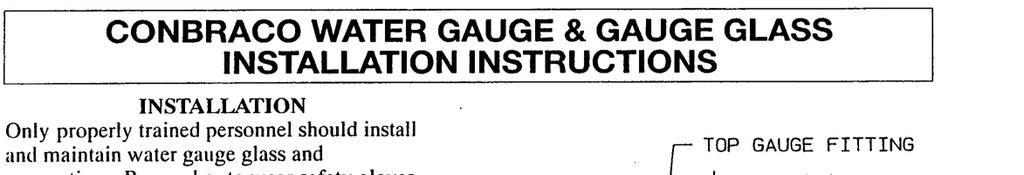
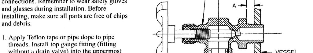
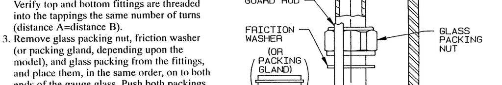
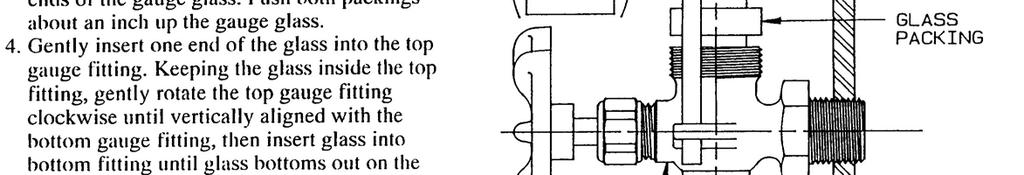

33
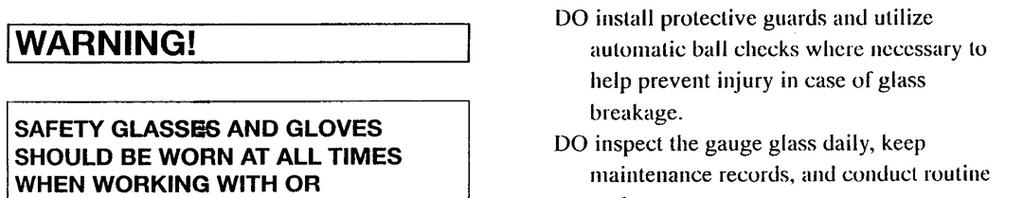
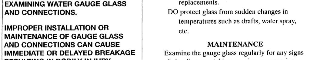
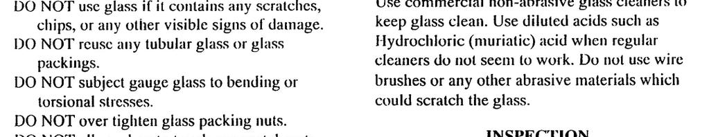
34
. Can be used with steam, air, non-combustible gases, or fluids non-corrosive to the pressure sensing element.")
35 L404A-D,F; L604A,L,M Pressuretrol Controllers L404 and L604 Pressuretrol Controllers are line voltage pressure controllers that provide operating control, automatic limit protection, or manual reset limit protection for pressure systems of up to 300 psi (21.1 kg/cm 2 or 2068 kpa). Can be used with steam, air, non-combustible gases, or fluids non-corrosive to the pressure sensing element. Stainless steel diaphragm (except 300 psi [21.1 kg/ cm 2 (2068 kpa)] models) also allows use with ammonia, oxygen, distilled water, and similar media. L404B is recommended for supervision of atomizing medium pressure in oil burner systems. Models are available with spst, spdt, or dpst switching and in variety of operating ranges. Dustproof, trouble-free mercury switches (all models except L404F, which has snap-acting switch). Automatic reset models have adjustable, subtractive differential (except L604M). Trip-free mechanism on manual reset models assures that limit function of controller cannot be defeated by jamming reset lever. Screw adjustments made on top of case. Scaleplates marked in English (psi) and Metric (kg/cm 2 ) units. L404F models available with European enclosure, British Standard Pipe Threads, ground screw, and scaleplates marked in kg/cm 2 and either psi or kpa. Clear plastic cover on case to observe pressure settings and switch action. Leveling indicator visible through cover. Hexagonal fitting with 1/4-18 NPT internal threads for direct mounting to Steam Trap (siphon loop). Surface mount is available using screws through holes (knockouts) in case backing. CONTENTS Specifications... 2 Ordering Information... 2 Installation... 5 Setting and Checkout... 8 Service Information L. Z. Rev Honeywell Inc
36 L404A-D,F; L604A,L,M SPECIFICATIONS ORDERING INFORMATION TRADELINE MODELS TRADELINE models are selected and packaged to provide ease of stocking, ease of handling, and maximum replacement value. Specifications of TRADELINE controls are the same as those of standard models except as noted below. TRADELINE MODELS AVAILABLE: L604A Pressuretrol Controllers Available in 2 to 15, 5 to 50, 10 to 150, and 20 to 300 psi (.14 to 1.1 kg/cm 2 [14 to 103 kpa],.4 to 3.5 kg/cm 2 [34 to 345 kpa],.7 to 10.6 kg/ cm 2 [69 to 1034 kpa], and 1.4 to 21.0 kg/cm 2 [138 to 2068 kpa]). ADDITIONAL FEATURES: TRADELINE pack with cross-reference label. STANDARD MODELS MODELS: L404A-D,F and L604A,L,M Pressuretrol Controllers. See Table 1. A Steam Trap (siphon loop) Specifications is available, except where noted in Table 1. The steam trap is necessary for boiler installations. SWITCH(ES): Mercury switch(es) in all models except the L404F, which has a Micro Switch snap-acting switch. PRESSURE SENSING ELEMENT: Stainless steel diaphragm (brass bellows in 300 psi [21.1 kg/cm 2, (2068 kpa)] models). MAXIMUM AMBIENT TEMPERATURE: 150 F (66 C). MINIMUM AMBIENT TEMPERATURE: Minus 35 F (minus 37 C); also refer to the note in the Location and Mounting section. ADJUSTMENT MEANS: Screws on top of controller case. Scales are marked in psi and kpa. ELECTRICAL CONNECTIONS: Internal screw terminals; hole in side of case for 1/2 in. conduit. MOUNTING MEANS: Hexagonal fitting on diaphragm has 1/4-18 NPT internal threads for mounting on a pipe or steam trap (siphon loop). Also can be surface-mounted using screws through two holes (knockouts) in back of case. Ordering Information When purchasing replacement and modernization products from your TRADELINE wholesaler or distributor, refer to the Tradeline Catalog or price sheets for complete ordering number, or specify 1. Order number (TRADELINE model, if desired). 2. Operating range (see Table 1). 3. Model without steam trap, if desired and available (see Table 1, Note b). 4. Optional specifications, if desired (see Table 1). 5. Replacement parts, if desired. 6. Accessories, if desired. If you have additional questions, need further information, or would like to comment on our products or services, please write or phone: 1. Your local Home and Building Control Sales Office (please check the white pages of your phone directory). 2. Home and Building Control Customer Logistics Honeywell Inc., 1885 Douglas Drive North Minneapolis, Minnesota (612) In Canada Honeywell Limited/Honeywell Limitée, 740 Ellesmere Road, Scarborough, Ontario M1P2V9. International Sales and Service Offices in all principal cities of the world. Manufacturing in Australia, Canada, Finland, France, Germany, Japan, Mexico, Netherlands, Spain, Taiwan, United Kingdom, U.S.A
37 TABLE 1 MODELS AVAILABLE. Switching Action on Midscale Subtractive Differential a Pressure Rise Operating Ranges a (Adjustable) L404A-D,F; L604A,L,M SPECIFICATIONS L604M spdt circuit 10 to to to 1034 fixed: 3.5 psi (24.1 kpa) makes R-W, breaks R-B a Scaleplates are marked in both psi and kg/cm 2 b Model available with special fixed low differential. Switch rated for 0.5A at 120 Vac. c L404A,B and L604A models are available with 1 to 6 psi midscale subtractive differential in 2 to 15 psi models. d Brass bellows replaces stainless steel diaphragm. Not suitable for use with ammonia, oxygen, or other corrosive materials. e Model available with minimum operating pressure of 1.25 psi (0.09 kg/cm 2 or 8.62 kpa) and minimum subtractive differential of 0.5 psi (0.035 kg/cm 2 or 3.45 kpa). f Model available with special fixed low differential. Switch rated for 0.5A at 120 Vac. g L404C,D and L604L models are designated as Manual Reset 2 controllers; the trip-free reset mechanism does not permit the controller to function as an automatic-reset device when the manual reset lever is held in the reset position. The subtractive differential is fixed at the minimum value of the adjustable differential of the L404A for each corresponding operating range. h L404F only; all other models have mercury switches. i Model available with sealed bell crank adjustment. j Spst switches operate in unison; spdt action when jumper is installed between R1 and R2. k Also recommended for supervision of atomizing medium pressure (air or steam) in an oil burner system. SWITCH CONTACT RATING (in amperes at 50/60 Hz): Model Load 120 Vac 240 Vac 120 Vdc 240 Vdc L404A L604A,L b Full Load Locked Rotor Noninductive a Full Load Locked Rotor Noninductive a L404F (snap-acting) does not have non-inductive or dc ratings. b L604A and L have also been tested (and listed by Underwriters Laboratories Inc.) and breaking (not making) a load with a total rating of 9.8 A full load, plus 360 VA ignition, plus 250 VA pilot duty at 120 Vac Maximum Surge Pressure Model to Setpoint psi kg/cm 2 kpa psi kg/cm 2 kpa psi kg/cm 2 kpa L404A L404B i L404C L404D L404F L604A L604L spst, breaks circuit spst, makes circuit spst, breaks circuit spst, makes circuit spdt snap-acting switch, h makes R-W, breaks R-B 2 isolated spst circuits, or 1 spdt, j makes R1- W, breaks R2-B spdt circuit makes R-W, breaks R-B 2 to 15 b,c 5 to to 150 b 20 to 300 d 2 to 15d, c,e,f 5 to to 150 e,b 20 to 300 d 2 to 15 5 to to to 300 d 2 to to to 15 5 to 50 i 10 to to 300 d 2 to 15 c 5 to to to 300 d.14 to to to to to to to to to to to to to to to to to to to to to to to to to to to to to to to to to to to to to to to to to to to to to 6 4 to 12 8 to to 40 2 to 6 4 to 12 8 to to to to to to to to to to to to to to to to to to 276 manual reset (fixed, subtractive differential) manual reset g (fixed, subtractive differential) 2 to 6 6 to to to 50 2 to 6 4 to 12 8 to to to to to to to to to to to to to to to to to to to to to 103 manual reset g (fixed, subtractive differential) L604M Full Load
38 L404A-D,F; L604A,L,M SPECIFICATIONS DIMENSIONS: See Fig. 1. See Fig. 2 for mounting steam trap (siphon loop). WEIGHT: 2 IBC. (0.91 kg). FINISH: Gray. APPROVALS: Underwriters Laboratories Inc. listed (L404A,B,C,D,F; L604A,L,M only): file no. MP466, vol.10; guide no. MBPR. Canadian Standards Association certified (L404A,B,C,D,F; L604A,L only): file no. LR1620; guide no.400-e-0. REPLACEMENT PARTS: Thermoplastic Cover Steam Trap (siphon loop) 1/4 in. black iron pipe. Necessary for boiler installations. ACCESSORIES: 33312B Knurled Adjustment Knob with setscrew; fits on main scale pressure adjusting screw. 4074BWJ Limit Stop Assembly to limit set point ranges; includes Range Stop, Range Stop Screw, and Wrench. TABLE 2 CONVERSION TABLE (psi to kpa). Operating Range Subtractive Differential Scale-Plate Equivalent Scale-Plate Equivalent (psi) (kg/cm 2) (kpa) (psi) (kg/cm 2) (kpa) 0 to 15 0 to 10 0 to to to to to 6 2 to 6 07 to 4.14 to.4 7 to to 41 5 to 50.3 to to to 12 5 to 14.3 to.8.4 to to to 97 5 to to to to to to to to 22.6 to to to to to to to to to to to to to 345 Fig. 1 Mounting dimensions of the L404A,B,C,D,F and L604A,L,M Pressuretrol Controllers, in in. (mm). L404A-D,F; L604A,L,M 1-15/16 (49.2) 3-3/16 (81.0) 1-5/32 (29.4) 4-1/2 (114.3) (COVER) 4-11/32 (110.3) (CASE) 1-61/64 (49.6) 1 2-3/4 (69.9) 1 1-1/16 (27.0) 13/16 (20.6) 1/2 (12.7) 3-7/8 (98.4) 3-23/32 (94.5) 4-31/32 (126.2) /16 (46.0) 3 13/16 (20.6) 3/16 (4.8) X 21/64 (8.3) KNOCKOUT (2) 7/8 (22.2) DIA. 2-1/8 (54.0) 1/4-18 NPT 1-3/16 (30.2) 1-1/16 (27.0) 1 RESET LEVER (ON MANUAL RESET MODELS ONLY.) 1-1/2 (38.1) 2 3 THIS DIMENSION IS 4-27/32 IN. (123.0 MM) ON L604 MODELS WITH A 2 TO 15 PSI (.14 TO 1.0 kg/cm 2 (14 TO 103 kpa)) OPERATING RANGE, AND 5-3/4 IN. (146.A MM) ON L604 MODELS WITH A 20 TO 300 PSI (1.4 TO 20.7 kg/cm 2 (138 TO 2068 kpa) OPERATING RANGE. ONLY ON L604 MODELS WITH A 2 TO 15 PSI (.14 TO 1.0 kg/cm 2 (14 TO 103 kpa)) OPERATING RANGE. M
39 L404A-D,F; L604A,L,M INSTALLATION Installation WHEN INSTALLING THIS PRODUCT Read these instructions carefully. Failure to follow them could damage the product or cause a hazardous condition. 2. Check the ratings given in the instructions and on the product to make sure the product is suitable for your application. 3. Installer must be a trained, experienced, flame safeguard control technician. 4. After installation is complete, check out product operation as provided in these instructions. CAUTION 1. Disconnect power supply before beginning installation to prevent possible equipment damage or electrical shock. 2. When using the controller with a compressor, install a dampening device (such as a needle valve, header, or surge tank) to dampen pulsations that can damage the controller or reduce its life. Fig. 2 Right and wrong mounting of a steam trap (siphon loop), with approximate dimensions in in. (mm). 4-1/2 TO 5-1/2 (114.3 TO 139.7) PRESSUR CONTROLLER TEE BOILER PRESSURE GAUGE STEAM TRAP (SIPHON LOOP) CORRECT BOILER 2-1/4 (57.2) DIA. INCORRECT IMPORTANT: 1. Locate the controller where the ambient temperature will not exceed 150 F (66 C). 2. Use pipe compound sparingly to avoid clogging the hole in the pipe or diaphragm fitting. 3. Do not tighten the controller by hand by holding the case. 4. Accurately level the controller for proper operation. LOCATION AND MOUNTING NOTE: For most accurate operation; add supplemental heat to installations where the temperature falls below minus 20 F (minus 29 C). Never locate the controller where the temperature falls below minus 35 F (minus 37 C), because mercury in the switch freezes at this temperature. When used with steam boilers, always mount the controller above the water line in the boiler. A steam trap (siphon loop) must always be connected between the controller and the boiler (Fig. 2) to prevent boiler scale and corrosive vapors from attacking the diaphragm. The loop on the steam trap must always be perpendicular to the face of the controller. If the loop is parallel to the controller, expansion or contraction of the loop tips the controller and causes the switch to operate inaccurately. The controller can be mounted (1) alongside the pressure gauge, (2) in a fitting on the boiler provided by the manufacturer, (3) at a remote location in case of excessive vibration, or (4) in a special mounting on a low water cutoff. 1 1/4 IN. BLACK IRON PIPE WITH 1/4-18 NPT EXTERNAL TRHEADS ON BOTH ENDS. BEND THE STEAM TRAP (SIPHON LOOP) TO LEVEL THE CONTROLLER. M8934 Make all pipe connections in accordance with approved standards. Use only a small amount of pipe compound to seal the connection joints. Excess pipe compound can clog the small hole in the fitting and prevent the controller from operating properly. To avoid leaks and damage to the case, use a parallel jaw wrench on the controller s hexagonal fitting. Do not tighten the controller by hand by holding the case. Leveling A controller with a mercury switch must be accurately leveled for proper operation. It is level when the leveling indicator (Fig. 11) hangs freely with its pointer directly over the index mark inside the back of the case. Level the controller by carefully bending the steam trap (siphon loop). Mounting Alongside a Pressure Gauge To mount the controller alongside a pressure gauge (Fig. 2), remove the gauge. In its place, install a steam trap (siphon loop) with a tee on top. Using elbows and pipe nipples, mount the controller and pressure gauge on the ends of the tee. Level the controller after installation
40 L404A-D,F; L604A,L,M INSTALLATION Mounting on a Boiler If it is not convenient to mount the controller alongside the pressure gauge, install a steam trap (siphon loop) in the fitting provided by the boiler manufacturer. If there is no fitting, mount the steam trap at a location recommended by the boiler manufacturer. Screw the controller directly to the steam trap, and level the controller. Mounting at a Remote Location If there is excessive vibration at the boiler that can adversely affect the operation of the controller, mount the controller at a remote location. All piping from the boiler must be suitable and solidly mounted. The piping must be properly pitched to drain all condensation back to the boiler. A steam trap (siphon loop) must be mounted between the remote piping and the controller. Level the controller after installation. Supervision of Atomizing Medium Pressure (Air or Steam) L404B When air or steam is used as an atomizing medium in an oil burner system, authorities having jurisdiction (approval bodies and codes) often require a low limit to prevent opening the main oil valve until sufficient atomizing pressure is present, and to shut down the system when the atomizing pressure falls too low. The L404B is recommended for this application. It makes a circuit when the pressure rises to the set point, and breaks when the pressure falls to the set point minus the differential (Fig. 10). WIRING 1. Disconnect the power supply before beginning wiring to prevent electrical shock or equipment damage. 2. Assume all wiring complies with applicable electrical codes, ordinances, and regulations. Use NEC Class 1 (line voltage) wiring. 3. For normal installations, use moisture-resistant No. 14 wire suitable for at least 167 F (75 C) when you are using the controller with a flame safeguard primary control, or at least 194 F (90 C) when using it with a programming control. 4. For high temperature installations, use moisture-resistant No. 14 wire, selected for a temperature rating above the maximum operating temperature. 5. All models have a terminal block inside the cover (Fig. 3 and 4) and a 7/8 in. (22.2 mm) hole in one side for 1/2 in. conduit, cable, or wires. Remove the front cover by loosening the screw at the bottom of the main scale. 6. Refer to Fig. 5 through 9 for typical hookups. Follow the burner or boiler manufacturer s wiring diagram if provided. 7. Make sure the loads do not exceed the Switch Contact Ratings in the Specifications section. 8. Replace the front cover when wiring is completed. Fig. 3 L404 terminal blocks and internal schematics. RISE BREAKS ON PRESSURE RISE TO SETPOINT RISE RISE L404A,C L404B,D L404F (SNAP-ACTING) MAKES ON PRESSURE RISE TO SETPOINT Fig. 4 L404 terminal block and internal schematic. RISE 1 1 JUMPER B R2 R1 W L604A MAKES R1-W BREAKS R2-B ON PRESSURE RISE TO SETPOINT. RISE SPDT SWITCH ACTION WITH JUMPER INSTALLED; OTHERWISE, TWO ISOLATED SPST SWITCHES. W R W B R R W B B BREAKS R-B, MAKES R-W ON PRESSURE RISE TO SETPOINT B R W L604L,M M8941 M8935 Fig. 5 L404 used as a limit or as an operating controller. L1 (HOT) POWER SUPPLY 1 2 L2 1 SPST CONTROLLER 2 PROVIDE DISCONNECT MEANS AND OVERLOAD PROTECTION AS REQUIRED. HIGH LIMIT L404A OR C BREAKS WHEN PRESSURE RISES TO SETPOINT. LOW LIMIT L404B BREAKS WHEN PRESSURE FALLS TO SETPOINT MINUS DIFFERENTIAL. OPERATING CONTROLLER L404A BREAKS WHEN PRESSURE RISES TO SETPOINT, AND MAKES AGAIN WHEN PRESSURE FALLS TO SETPOINT MINUS DIFFERENTIAL. M8936 L2 FLAME SAFEGUARD CONTROL, MOTOR, OR OTHER LOAD
41 L404A-D,F; L604A,L,M INSTALLATION Fig. 6 L404 with a low voltage relay. Fig. 8 L404F, L604A (with jumper installed) or L604M, used as a low limit, with an alarm circuit. 24 VOLT THERMOSTAT LOW VOLTAGE RELAY 1 2 L404 POWER SUPPLY L1 (HOT) 1 L2 SPDT CONTROLLER (HIGH LIMIT) W 2 B R THERM L1 (HOT) POWER SUPPLY L2 1 L2 FLAME SAFEGUARD CONTROL, MOTOR, OR OTHER LOAD LOAD 1 PROVIDE DISCONNECT MEANS AND OVERLOAD PROTECTION AS REQUIRED. M ALARM PROVIDE DISCONNECT MEANS AND OVERLOAD PROTECTION AS REQUIRED. 2 BREAKS R TO B AND MAKES R TO W WHEN PRESSURE RISES TO SETPOINT. M8938 Fig. 7 L404F, L604A (jumper installed) used as a high limit, with an alarm circuit. L1 (HOT) POWER SUPPLY L SPDT CONTROLLER (LOW LIMIT) W 2 R ALARM B PROVIDE DISCONNECT MEANS AND OVERLOAD PROTECTION AS REQUIRED. BREAKS R TO W AND MAKES R TO B WHEN PRESSURE FALLS TO SETPOINT MINUS DIFFERENTIAL. M8937 L2 FLAME SAFEGUARD CONTROL, MOTOR, OR OTHER LOAD Fig. 9 L404F, or L604 with jumper installed, controlling an M644B motor. L1 (HOT) POWER SUPPLY L2 1 SPDT CONTROLLER 2 1 W B R WHITE RED BLUE BLACK BLACK LINE VOLTAGE TWO-POSITION MOTOR W1 CLOSED (LOW FIRE) R1 PROVIDE DISCONNECT MEANS AND OVERLOAD PROTECTION AS REQUIRED. B1 L1 L2 OPEN (HIGH FIRE) M644B 2 BREAKS R TO B AND MAKES R TO W WHEN PRESSURE RISES TO SETPOINT. M
42 L404A-D,F; L604A,L,M SETTING AND CHECKOUT SETTING In all models, the differential is subtractive from the main scale set point. The upper operating point is determined by the main scale set point, while the lower operating point is determined by the main scale setting less the differential setting. The L404F and L604A (with jumper installed), L,M have spdt switching action. Operating points are shown in Fig. 10. Setting and Checkout main scale setpoint. They will not automatically return to their former positions. To reset one of these controllers, wait until the pressure falls to the set point minus the differential (Fig. 10). Then depress the manual reset lever (Fig. 11) and release it. The controller will not be reset until you release the manual reset lever. This prevents the controller from becoming an automatic-reset device if the reset lever is stuck, held in, or tied down. Fig. 10 L404 and L604 operating points. Fig. 11 Setting a Pressuretrol Controller. L404A,C PRESSURE RISE MAIN SCALE SETPOINT (SWITCH BREAKS) SUBTRACTIVE DIFFERENTIAL DIFFERENTIAL SETTING (SWITCH MAKES) 1 DIFFERENTIAL ADJUSTING SCREW 1 SCALEPLATES MAIN SCALE ADJUSTING SCREW 2 MANUAL RESET LEVER MERCURY SWITCH MAIN SCALE SETPOINT (SWITCH MAKES) L404B,D PRESSURE RISE L404F; L604L,M PRESSURE RISE SUBTRACTIVE DIFFERENTIAL DIFFERENTIAL SETTING (SWITCH BREAKS) MAIN SCALE SETPOINT (BREAKS R-B, MAKES R-W) SUBTRACTIVE DIFFERENTIAL DIFFERENTIAL SETTING (MAKES R-B, BREAKS R-W) DIFFERENTIAL SETTING INDICATOR DIFF PSI MAIN L604A PRESSURE RISE MAIN SCALE SETPOINT (MAKES R1-W, BREAKS R2-B) SUBTRACTIVE DIFFERENTIAL DIFFERENTIAL SETTING (BREAKS R1-W, MAKES R2-B) L404C,D AND L604L MANUAL RESET MODELS HAVE A SMALL, FIXED DIFFERENTIAL. THEY CAN BE MANUALLY RESET WHEN THE PRESSURE FALLS TO THE MAIN SCALE SETPOINT MINUS THE DIFFERENTIAL. 1 MAIN SCALE SETTING INDICATOR DIAPHRAGM ASSEMBLY POINTER LEVELING INDICATOR INDEX MARK ADJUSTABLE DIFFERENTIAL ON THE L404A,B,F; L404L WITH A 5 TO 150 PSI (0.34 TO 10.3 kg/cm 2 [34 TO 134 kpa] OPERATING RANGE; AND L604A MODELS ONLY. 2 L604M HAS A SMALL, FIXED DIFFERENTIAL OF 3.5 PSI (0.25 kg/cm2) OR 24.1 kpa.) M TRIP-FREE MANUAL RESET LEVER ON THE L404C,D AND L604L MODELS ONLY. M8943 Adjust the main scale set point for the desired operating pressure by turning the main scale adjusting screw (Fig. 11) on the top of the case until the main scale setting indicator is at the desired value. On an L404A,B,F with a 5 to 150 psi (.3 to 10.3 kg/cm 2 [34 to 1034 kpa]) operating range, or an L604A, adjust the differential setting by turning the differential adjusting screw (Fig. 11) until the differential setting indicator is at the desired value. L404C,D and L604L are manual reset models: see the next paragraph. The L604M has a fixed differential. The scaleplates are marked psi and kg/cm 2. Trip-Free Manual Reset Feature (L404C,D and L604L only) The L404C breaks, the L404D makes, and the L604L makes R-W and breaks R-B when the pressure rises to the CHECKOUT After the controller has is installed, wired, and set, test it with the system in operation. First allow the system to stabilize. Then observe the operation of the controller while raising and lowering its setpoint. Pressure should increase when the setpoint is raised and decrease when the set point is lowered. Also check the make and break points of the controller. If they do not agree with a separate, accurately calibrated pressure gauge, a slight adjustment of the scaleplate(s) may be necessary. Use accurate pressure testing equipment when checking out the controller. Do not rely on inexpensive gauges. The controllers are carefully calibrated at the factory
43 L404A-D,F; L604A,L,M SETTING AND CHECKOUT Boiler Installation If the controller is being used on a boiler installation, test it as follows: 1. Note the boiler pressure by checking the boiler pressure gauge. (To perform this test properly, the boiler should have a pressure reading near the middle of the controller s main scale range.) 2. Turn the main scale adjusting screw (Fig. 11) until the main scale setting indicator on the controller corresponds to the boiler pressure gauge reading. 3. The L404A or C should break the control circuit(s) automatically when the boiler pressure gauge reading equals or slightly exceeds the controller setting. The L404B or D should make the circuit under the same circumstances. The L404F; L604L,M should make the R-W circuit and break the R-B circuit under the same circumstances. The L604A should make the R1-W circuit and break the R2-B circuit under the same circumstances. 4. If the controller is operating properly, turn the main scale adjusting screw (Fig. 11) until the main scale setting indicator is at the desired set point. If a Controller Seems to Operate Improperly If the controller is suspected of operating improperly, it may be further checked as follows (Fig. 12): 1. Disconnect all power to the controller, loosen the cover screw, and remove the cover. 2. Disconnect the wires from the controller. 3. Connect an ohmmeter between the switch terminals. 4. Lower the set point of the controller (simulating a pressure increase) through a range greater than the differential. The switch should either make or break, depending on the model of the controller. (An L404A or C should break, an L404B or D should make, an L404F; L604L,M should break R-B and make R-W, and an L604A should break R2-B and make R1-W.) If it makes, the ohmmeter reads zero; if it breaks, the ohmmeter reads infinity. 5. Raise the set point of the controller (simulating a pressure decrease) through a range greater than the differential. The switch should break or make, just the opposite of its action in step 4 (except for the L404C,D and L604L manual reset models). NOTE: An approximation of the differential can be made by observing the change in set point required for a resistance change from zero to infinity. 6. If the controller operates improperly, replace it. 7. When the controller is operating properly, reconnect the wires to the terminal block, replace the cover and tighten the cover screw, and reconnect the power. CAUTION Do not put the system into service until you have satisfactorily completed all applicable tests described in this Checkout section, in the Checkout section of the applicable instructions for the flame safeguard control, and any others required by the burner and boiler manufacturers. Fig. 12 Checking controller operation using an ohmmeter. DIFFERENTIAL SETTING INDICATOR MAIN SCALE SETTING INDICATOR OHMMETER INPUT ZERO ADJ DIFF MAIN PSI KG CM 2 KG CM 2 DIFF. IS SUBTRACTIVE OUTPUT 0 MAIN SCALE ADJUSTING SCREW PSI B W R1 R2 R W SETPOINT DECREASE ZERO OHMS (INFINITY WHEN R-B BREAKS) 1 AN L604, WITH JUMPER INSTALLED BETWEEN R1 AND R2, IS SHOWN; AN L404F OPERATES SIMILARLY (SPDT SWITCHING). AN L404A, B, C OR D HAS ONLY TWO TERMINALS (SPST SWITCHING); AN L404A OR C BREAKS AND L404B OR D MAKES WHEN THE SETPOINT IS DECREASED FAR ENOUGH. M B
44 L404A-D,F; L604A,L,M SERVICE INFORMATION Service Information CALIBRATION The controller was carefully calibrated during manufacturing and should not require recalibration. Most calibration errors are caused by improper leveling. The controller should be level when the pointer on the leveling indicator is directly over the index mark (Fig. 11). In some cases, the leveling indicator may not be accurate enough. The pointer may be over the index mark, but the controller still may not be operating within the tolerance of its scale setting. In this case, carefully bend the steam trap (siphon loop) until the controller switches properly. MAINTENANCE The cover of the controller should be in place at all times to protect the internal components from dirt, dust, and physical damage. Routine maintenance should consist of occasional inspection and blowing or brushing away any accumulated dirt and dust. To ensure proper functioning of the controller at all times, perform an operational check of the entire system during routine maintenance checks
45 KUNKLE PRESSURE RELIEF VALVES Installation and Operating Instructions Pre-Installation Handling This pressure relief valve is designed to protect equipment from overpressure. The valve should be handled with care, not subjected to heavy shock loads, and protected to prevent contamination from getting inside. It should be installed correctly per A.S.M.E. Boiler & Pressure Vessel Code requirements. Failure to do so could result in property damage or serious injury to personnel. When hoisting the valve into position for installation, care should be exercised so that lifting straps do not contact the valve lift lever. Installation Always wear proper safety equipment, including safety glasses and ear protection. 1. Mount the valve in a vertical position so that the valve body is self-draining. If a body drain port is provided, make sure it is open when required by the ASME code. Do not plug any bonnet vent openings. The inlet piping should be as short as possible, with no elbows, and equal to or greater than the size of the pressure relief valve inlet connection. This will help to limit the inlet pressure drop to 3% or less when the valve is relieving. 2. When discharge piping is connected to valve outlet, make sure it is self draining if a body drain port is not used. The valve should not be connected to any discharge pipe that contains pressure before the valve opens or to any pipe where the pressure build-up is greater than 10% of the set pressure when the valve is open and relieving. Discharge piping, other than a short tailpipe, must be supported. For steam service, a drip pan elbow or flexible connection between the valve and the pipe should be used to prevent excessive pipe stress, due to thermal expansion, from being imposed on the valve body. 3. For threaded valves, to prevent sealing compound from entering and damaging the valve, apply a small amount of pipe thread sealing compound to external threads only. Do not put any sealing compound on the first thread or on any internal threads. To do so may cause the sealing compound to enter the valve and cause seat leakage. Do not use the valve body or bonnet for installing the valve in threaded connections. Use the wrench flats provided to tighten the valve to the connecting pipe, and do not overtighten. To do so may cause valve leakage. 4. For flanged valves, use new gaskets and tighten the mounting studs evenly. Operation 1. Maintain a system operating pressure at least 5 psig or 10% below the set pressure of the valve, whichever is greater. Operating too close to the valve set pressure will cause seat leakage and will shorten the time between valve maintenance. 2. Do not use the safety valve as a control valve to regulate system operating pressure. Excessive operation will cause the seat to leak and will require more frequent valve maintenance. 3. ASME Section I and VIII valves equipped with lift levers are designed to be operated only when the system pressure is 75% of set pressure or greater. ASME Section IV valves may be operated at any set pressure. When hand operating the valve, hold it open long enough to purge any foreign matter from the seat area. If a cable or wire is attached to the lift lever for remote actuation, make sure the direction of pull is the same as it would be if the lever were pulled directly by hand. Maintenance Maintenance should be performed on a regular basis. An initial inspection interval of 12 months is recommended. Depending on the service conditions and the condition of the valve, the inspection interval may be decreased or increased. Use only Kunkle parts for repair. Depending on the local jurisdictional requirements where the valve is installed, repairs may have to be made by a repair facility holding a VR stamp. WARNING! Removal of the seal wires or any attempt to adjust, repair or modify this product by non-qualified or non-authorized persons voids the product guarantee and may cause serious damage to equipment, personal injury, and death. Kunkle Valve is not liable for any damage resulting from misuse or misapplication of its products. Kunkle Valve Division Rev B 01/14/2002 Phone: Old US 70, Black Mountain, NC Fax:
46 BULLETIN MS /04 Gas Appliance Pressure Regulators Straight-Thru-Flow Design RV52, RV53, RV61, RV81, RV91, RV111, and RV131 1/2", 3/4", 1", 1¼", 1½", 2", 2½", 3" & 4" design certified Maximum Pressure CSA Rated (except RV131)... 1/2 psi (35 mbar) Maxitrol Tested* RV52 & RV /2 psi (35 mbar) RV61, RV81, RV91, & RV psi (70 mbar) RV psi (140 mbar) * Do not use if inlet pressure is more than 10 times desired outlet pressure EMERGENCY EXPOSURE LIMITS (Maxitrol Tested) RV52 & RV psi (210 mbar) RV61, RV81, RV91 & RV psi (350 mbar) RV psi (1050 mbar) GAS CONTAINMENT EXPOSURE LIMITS* RV 52 & RV psi (1050 mbar) RV61, RV81, RV91, RV111, & RV psi (1750 mbar) * Please note that internal damage may occur when exposed to these pressures. AMBIENT TEMPERATURE LIMITS RV52, RV53, RV61, RV81, RV91 & RV to 205 F (-40 to 96 C) RV to 125 F (-40 to 52 C)... S-T-F Series GASES: Natural, manufactured, mixed, liquefied petroleum, or LP gas-air mixture.

47 Straight-Thru-Flow Design RV series RV52, RV53, RV61, RV81, RV91, RV111, and RV131 FEATURES Greater accuracy higher pressure drop capacity Outlet pressures available to 42 w.c. Available in full range of pipe sizes from 1/2" to 4" All models tapped with NPT vent bosses CSA Design Certified (except RV131) BENEFITS Unique conical valve design fills need of combining good regulation with high capacity in low to intermediate pressure range Allows more pressure drop to be assigned to piping and valves permits reduction in manifold size Provides accurate, sensitive regulation at inlet pressures as low as 3 w.c. RV131 only, provides bonus benefits of high capacity and good performance at pressures of 1 psi or higher Ease of installation and replacement All models except RV131 are CSA design certified for 1/ 2 psi rated pressure under the ANSI standard for gas pressure regulators; and CSA listed to certify compliance with nationally published safety, construction, and performance standards. They are main burner only, non-lockup type. They should not be used as a line gas pressure regulator ahead of low pressure controls. Use only where downstream controls can operate at line pressure. Refer to other Maxitrol sales bulletins for proper types. The RV52, RV53, & RV61 are suitable for multipoise mounting. The RV81, RV91, RV111, & RV131 are recommended for normal horizontal position only. Maxitrol's original Straight-Thru-Flow design meets your needs for high capacities at low inlet pressures. The basic difference between S-T-F design and other type regulators lies in the conical valve. The cone principal permits gas to flow straight through the regulator without changing directions. Frictional flow resistance is reduced, resulting in greater capacity. The improved flow pattern provides accurate sensitive regulation at extremely low pressure differentials. The ability of the regulator to handle large capacity appliances with limited supply pressure offers a definite advantage to designers of commercial and industrial gas-fired equipment. Models up to the three inch pipe size have high strength pressure cast aluminum housings. The RV131 four inch model is of cast iron and steel construction. RV61, RV81, RV91, RV111, & RV131 internal conical valves are coated with Teflon for long life. Diaphragm material is cut from the finest synthetic coated fabrics available. All other parts are carefully specified corrosion-resistant or plated material. Pipe sizes of 1/2, 3/4, 1, 1-1/4, 1-1/2, 2, 2-1/2", 3, and 4 are available. Models through the 3" size are threaded, the 4" RV131 is flanged. At the emergency exposure limits, there may be no regulation, but all models will contain gas. They will suffer no internal damage and will resume regulation when normal pressure is restored. Straight-Thru-Flow appliance regulators are intended for use with all fuel gases, and may also be used with air or other noncorrosive gases within their pressure limits. Typical applications include all types of residential, commercial and industrial gas-fired appliances and equipment used on low pressure gas supply. See Maxitrol s Spring Selection Chart for part numbers, color and size of springs. Teflon is a registered trademark of DuPont Corporation. NOTE: All Maxitrol appliance regulators should be installed in accordance with Maxitrol s Safety Warning bulletin. 2
48 Capacities and Pressure Drop CAPACITIES expressed in CFH (m 3 /h) 0.64 sp gr gas Model Number and Pipe Size A.G.A. CSA MAX Pressure DropÑinches w.c. (mbar) RV52 1/2 x 1/2 3/4 x 3/4 450 (12.7) 151 (4.2) 214 (6.1) 262 (7.4) 302 (8.5) 338 (9.5) 370 (10.5) 400 (11.3) 427 (12.1) 453 (12.8) 478 (13.5) 676 (19.1) 828 (23.4) 956 (27.1) RV53 3/4 x 3/4 1 x (20.1) 217 (6.1) 306 (8.6) 375 (10.6) 433 (12.2) 484 (13.7) 530 (15) 573 (16.2) 612 (17.3) 650 (18.4) 684 (19.3) 968 (27.4) 1185 (33.5) 1369 (38.7) RV61 1 x 1 1-1/4 x 1-1/ (31.1) 379 (10.7) 536 (15.1) 675 (19.1) 759 (21.5) 848 (24) 929 (26.3) 1004 (28.4) 1073 (30.4) 1138 (32.2) 1200 (34.0) 1742 (49.3) 2134 (60.4) 2464 (69.8) RV81 1-1/4 x 1-1/4 1-1/2 x 1-1/ (70.8) 780 (22.1) 1102 (31.2) 1350 (38.2) 1559 (44.1) 1743 (49.5) 1909 (54) 2062 (58.4) 2204 (62.4) 2339 (66.2) 2465 (69.8) 3485 (98.7) 4269 (120) 4929 (139) RV91 2 x 2 2-1/2 x 2-1/ (92.7) 1212 (34.3) 1714 (48.5) 2100 (59.4) 2424 (68.6) 2711 (76.7) 2969 (84.1) 3208 (90.8) 3429 (97.1) 3637 (103) 3834 (108) 5422 (153) 6640 (188) 7668 (217) RV /2 x 2-1/2 3 x (212) 2742 (78) 3878 (110) 4750 (134) 5485 (155) 6132 (175) 6718 (190) 7256 (205) 7757 (219) 8227 (233) 8572 (243) (343) (420) (486) RV131 4 x (134) Sizing Instructions 6695 (190) 8200 (232) 9468 (268) In order to select the proper size regulator, you must know the available inlet pressure, desired outlet pressure, and the required maximum flow rate. Example No. 1 To select a regulator of ample capacity to handle flow (300) KNOWN: Pipe size 2-1/2", flow rate 8,000 CFH (0.64 sp gr), inlet pressure 9" w.c., desired outlet pressure 5" w.c. SOLUTION: 1. Determine differential pressure available: Inlet pressure 9" w.c. Subtract outlet pressure - 5" w.c. Available differential pressure 4" w.c. 2. When determining capacity Maxitrol recommends that the pressure drop not exceed 1/2 of available differential pressure (1/2 of 4" w.c. = 2" w.c.). 3. Check Capacity Chart to determine which regulator has a pressure drop of 2" w.c. or less at a flow rate of 8,000 CFH. 4. The RV111 meets these standards with a flow rate of 12,134 CFH for the 2-1/2" pipe size at 2" w.c. pressure drop. The 2-1/2" RV91 flows 5422 CFH at 2" w.c. pressure drop. Therefore, the RV /2" is the correct regulator to use (328) (354) (380) (402) (424) (600) SOLUTION: 1. Check capacity Chart above for 4" regulator, RV Note that at a flow rate of 21,172 CFH the pressure drop is 2" w.c. 3. Multiply this by two to obtain recommended differential pressure (4" w.c.). 4. Subtract 4" differential pressure from 10" w.c. inlet pressure to obtain maximum recommended outlet pressure setting of 6" w.c. Pressure Drop Chart (734) (848) Example No. 2 To determine maximum recommended operating outlet pressure. KNOWN: Pipe size 4", flow rate 21,000 CFH, inlet pressure 10" w.c. 3
49 Dimensions and Spring Ranges RV81 & 91 RV52 & 53 A RV61 A A C DIMENSIONS* inches (millimeters) Model & Illustration Number D Vent Tap B Swing Radius C D Call-Outs A B C D B C RV111 D B A RV52 RV53 RV61 RV81 RV91 2" pipe 1/8" NPT 1/8" NPT 1/8" NPT 3/8" NPT 1/2" NPT 3.6 (91) 3.9 (99) 4.8 (122) 6.4 (162) 8.5 (216) 4.9 (124) 5.2 (132) 6.4 (164) 8.4 (213) 10.8 (275) 3.2 (81) 3.75 (95) 4.4 (111) 6 (153) 6.5 (165) 3.25 (83) 3.9 (99) 5.4 (138) 7 (178) 9.1 (232) 1.25 (32) 1.3 (33) 1.6 (41) 2 (51) 2.3 (60) C RV131 D B RV91 2.5" pipe RV111 RV131 1/4" NPT 3/4" NPT 3/4" NPT 8.3 (212) 11.5 (284) 18.2 (462) 10.5 (267) 15.1 (373) (590) 7.1 (181) 9 (229) 13.9 (353) 9.1 (232) 13.4 (324) 18 (458) 2.4 (62) 3.5 (89) 5.1 (129) C A * Dimensions are to be used only as an aid in designing clearance for the valve. Actual production dimensions may vary somewhat from those shown. D SPRING SELECTION CHART inches w.c. (mbar) B Model Number A.G.A. CSA Certified Springs Other Springs Available RV52 3 to 6 (7.5-15) 4-8 (10-20) 5-12 ( ) (2.5-9) 2-5 (5-12.5) 3-8 (7.5-20) 4-12 (10-30) RV53 3 to 6 (7.5-15) 4-8 (10-20) 5-12 ( ) (2.5-9) 2-5 (5-12.5) 3-8 (7.5-20) 4-12 (10-30) RV61 3 to 6 (7.5-15) 4-8 (10-20) 5-12 ( ) (2.5-9) 2-5 (5-12.5) 3-8 (7.5-20) (25-55) RV81 3 to 6 (7.5-15) 4-8 (10-20) 5-12 ( ) (2.5-9) 2-5 (5-12.5) 3-8 (7.5-20) 4-12 (10-30) 5-15 ( ) (25-55) RV91 3 to 6 (7.5-15) 4-8 (10-20) 5-12 ( ) (2.5-9) 2-5 (5-12.5) 3-8 (7.5-20) 4-12 (10-30) 5-15 ( ) (25-55) RV111 3 to 6 (7.5-15) 4-8 (10-20) 5-12 ( ) (2.5-9) 2-5 (5-12.5) 3-8 (7.5-20) 4-12 (10-30) 5-15 ( ) (25-55) RV131 3 to 6 (7.5-15) ( ) (5-12.5) 3-8 (7.5-20) 4-12 (10-30) (25-55) (38-75) (50-105) NOTE: The area within the heavy line indicates CSA certified springs. A copyrighted publication of Maxitrol Company Telegraph Rd., P.O. Box 2230 Southfield, MI U.S.A Fax European Representatives Warnstedter Strasse Thale, Germany Fax Industriestrasse Senden, Germany Fax
50 BULLETIN MI2010-5/00 SAFETY WARNING INSTRUCTIONS FOR MAXITROL GAS PRESSURE REGULATORS NOTE: GAS PRESSURE REGULATORS WILL NOT TURN OFF THE FLOW OF GAS. INSTRUCCIONES PARA PRECAUCIONES DE SEGURIDAD PARA REGULADORES DE PRESION DE GAS MAXITROL SPECIAL WARNINGS IF YOU DO NOT FOLLOW THESE INSTRUCTIONS EXACTLY, A FIRE OR EXPLOSION MAY RESULT CAUSING PROPERTY DAMAGE, PERSONAL INJURY OR LOSS OF LIFE. NO UNTRAINED PERSON SHOULD ATTEMPT TO INSTALL, MAINTAIN OR SERVICE GAS PRESSURE REGULATORS. To minimize the possibility of FIRE, EXPLOSION, and OTHER HAZARDS: 1. All products, including gas pressure regulators, used with combustible gas must be installed and used strictly in accordance with the instructions of the manufacturer, with government codes and regulations, and plumbing codes and practices. 2. Do not use a gas pressure regulator if it appears to have been subjected to high temperatures, damaged in any way, or to have been taken apart or tampered with. Any of these may be signs of possible leakage or other damage that may affect proper operation and cause potentially dangerous combustion problems 3. a. Install the regulator properly with gas flowing as indicated by the arrow on the casting. b. Use pipe compound or thread sealant, properly threaded pipes and careful assembly procedure so that there is no cross threading, etc., which might cause damage or leakage. c. Apply wrench or vise pressure only to the flat areas around the pipe tappings at the end being threaded to the pipe to avoid possible fracture of the regulator body which could result in leakage d. Make sure markings or wording on regulator are not painted over or obliterated. 4. Check carefully for gas leaks immediately after the regulator has been installed and the gas turned on. Do this before attempting to operate the appliance or other gas burning device. Use a rich soap solution (or other accepted leak tester) around the diaphragm flanges, bottom plate, vent opening, seal cap, pipe connections, and all other joints. Wipe clean with a damp rag. It is a good practice to periodically check for leakage during use of the appliance. Absolutely no leakage should occur, otherwise there is a danger of fire or explosion depending upon conditions. Never use if leakage is detected. CAUTION NEVER CONNECT REGULATOR DIRECTLY TO THE PROPANE SUPPLY SOURCE. MAXITROL REGULATORS REQUIRE AN EXTERNAL REGULATOR (NOT SUPPLIED). INSTALL THE EXTERNAL REGULATOR BETWEEN THE PROPANE SUPPLY SOURCE AND MAXITROL REGULATOR. NOTA: LOS REGULADORES DE PRESION DE GAS NO CORTAN EL FLUJO DE GAS PRECAUCIONES ESPECIALES! SI USTED NO SIGUE ESTAS INSTRUCCIONES EXACTAMENTE, PUEDE OCURRIR UN INCENDIO O UNA EXPLOSION, CAUSANDO DAÑOS A LA PROPIEDAD, LESIONES PERSONALES O PERDIDA DE VIDAS. NADIE QUE NO HAYA SIDO ENTRENADO DEBERA DE TRATAR DE INSTALAR, DAR SERVICIO O DAR MANTENIMIENTO A LOS REGULADORES DE PRESION DE GAS Para reducir la posibilidad de INCENDIO, EXPLOSION Y OTROS RIESGOS: 1. Todos los productos, incluyendo los reguladores de presión de gas, que se usan con gases combustibles deberán instalarse y usarse estrictamente de acuerdo con las instrucciones del fabricante, usando los códigos y reglamentos gubernamentales así como los códigos y prácticas de plomería. 2. No usar un regulador de presión de gas si parece haber estado expuesto a altas temperaturas, dañado en alguna forma o que se haya desmantelado o maltratado. Cualquiera de éstas pueden ser señales de posibles fugas u otros daños que pueden afectar el funcionamiento correcto y causar problemas de combustión potencialmente peligrosos. 3. a. Instalar el regulador correctamente con el gas fluyendo como se indica en la flecha en la carcasa de fundición. b. Usar un compuesto sellador de tubería o hilo sellador de rosca, tuberías correctamente roscadas y procedimientos de ensamble cuidadoso, asegurándose de que no haya trasroscados, lo cual podría causar daños o fugas. c. Aplicar únicamente la presión de una llave o tornillo de banco en las áreas planas alrededor de las roscas de la tubería del extremo a enroscar para evitar la posible rotura del cuerpo del regulador que podría resultar en fugas. d. Asegurarse de que no se pinten o tachen las marcas o escritura en el regulador. 4. Verificar inmediatamente que no haya fugas de gas después de que el regulador haya sido instalado y se haya abierto el paso del gas. Esto deberá hacerse antes de tratar de operar el aparato electrodoméstico o cualquier otro dispositivo quemador de gas. Usar una solución espesa de jabón (u otro probador de fugas aceptado) alrededor de las bridas del diafragma, el fondo del plato, la apertura de ventilación, la tapa selladora y las conexiones de la tubería y todas las demás juntas. Limpiar con un trapo húmedo. Es una buena práctica verificar periódicamente que no haya fugas durante el uso del aparato electrodoméstico. Absolutamente no deberá haber ninguna fuga. De otra forma hay peligro de incendio o explosión dependiendo de las condiciones. Nunca deberá usarse si se detectan fugas. PRECAUCION! NUNCA CONECTAR EL REGULADOR DIRECTAMENTE AL SUMINISTRO DE PROPANO. LOS REGULADORES MAXITROL REQUIEREN UN REGULADOR EXTERNO (NO PROVISTO). INSTALAR EL REGULADOR EXTERNO ENTRE EL SUMINISTRO DE PROPANO Y EL REGULADOR MAXITROL 5. Very high pressure surges in the gas supply line (or as a result of exposing the system to high pressure) may result in serious internal damage and cause leakage or affect regulator operation. If you suspect that a Maxitrol regulator has been exposed to more than twice the maximum operating inlet pressure, as shown in the following chart, turn off the gas and have the system checked by an expert. (over) 5. Aumentos grandes de presión en la línea de suministro de gas (o como resultado de exponer el sistema a alta presión) pueden resultar en daños internos y causar fugas o afectar el funcionamiento del regulador. Si usted sospecha que un regulador Maxitrol ha sido expuesto a más del doble de la presión máxima de entrada, como se muestra en la tabla siguiente, cierre el paso del gas y haga que el sistema sea verificado por un experto. (a la vuelta) Telegraph Rd. P.O. Box 2230 Southfield, MI U.S.A Phone Fax
51 6. Venting must be controlled in accordance with government and plumbing codes and regulations to avoid the danger of escaping gas should there be internal leakage. Vent pipes must be open and the open end protected against entry of foreign matter, including water. 7. The outlet pressure of the regulator must be measured to make sure it is in accordance with intended usage. If a spring change is required to develop the required outlet pressure, the spring must be one specified by MAXITROL 8. Caution should be used to guarantee that there is sufficient inlet pressure to achieve the desired outlet pressure and no readjustment of the outlet pressure setting should be made unless the inlet pressure is within the proper limits for the regulator. Failure to follow this may result in overfiring of the appliance or other gas burning device. The MAXITROL bulletin for the regulator should be consulted for specific inlet and outlet pressure relationships. 9. A MAXITROL regulator must be used within the temperature range and not in excess of the maximum inlet pressure shown in the following table and should be in the mounting position indicated. Maxitrol regulators can be used with all fuel gases. 10. In case of any doubt, please contact the Service Manager, Maxitrol Company, Southfield, MI USA. Phone: 248/ La ventilación deberá estar controlada de acuerdo con los códigos y reglamentos gubernamentales de plomería para evitar el peligro de que se escape el gas en caso de una fuga interna. Los tubos de ventilación deberán estar abiertos y el extremo abierto deberá estar protegido contra cualquier materia extraña, incluyendo el agua. 7. La presión de salida del regulador deberá medirse para asegurarse que está de acuerdo para el uso que se pretende. Si se necesita cambiar un resorte para desarrollar la presión de salida requerida, el resorte deberá ser especificado por MAXITROL y la nueva presión de salida deberá anotarse en el regulador. 8. Deberá usarse precaución para garantizar que hay suficiente presión interna para alcanzar la presión de salida deseada y no deberá hacerse ningún reajuste en la presión de salida a menos que la presión interna esté dentro de los límites correctos para el regulador. Si esto no se lleva a cabo podría resultar en una llama excesiva del aparato electrodoméstico u otro dispositivo quemador de gas. Deberá consultarse el boletín MAXITROL para el regulador para ver la relación específica entre la presión de entrada y la de salida. 9. Un regulador MAXITROL deberá usarse dentro del rango de temperatura y no deberá excederse la presión máxima de entrada que se muestra en la tabla siguiente y deberá estar en la posición indicada de montaje. Los reguladores MAXITROL pueden usarse con todo tipo de gases combustibles. 10. En caso de dudas, favor de comunicarse con el Service Manager (Gerente de Servicio), Maxitrol Company, Southfield, MI USA. Teléfono: Model Number (Número de Modelo) Maximum Operating Inlet Pressure (Presión Máxima de Entrada para Operación) Ambient Temperature Range (Rango de Temperatura Ambiente) Mounting Position [see below] (Posiciónde Montaje) [ver abajo] RV12LT, RV20LT 1/2 psi (34 mbar) -40 to 275 F (-40 to 135 C) A, B, C, D RV20L 2 psi (138 mbar) -40 to 225 F (-40 to 107 C) A, B, C, D RV47, RV48 (*1) 1/2 psi (34 mbar) 32 to 225 F (0 to 107 C) A, B, C, D, (*1) RV48T (*1) 1/2 psi (34 mbar) 32 to 275 F (0 to 135 C) A, B, C, D, (*1) RV52, RV53, (*1) 1/2 psi (34 mbar) -40 to 205 F (-40 to 96 C) A, B, C, D, (*1) RV61, (*1) 1 psi (69 mbar) -40 to 205 F (-40 to 96 C) A, B, C, D, (*1) RV81, RV91 1 psi (69 mbar) -40 to 205 F (-40 to 96 C) A only (únicamente) RV111 1 psi (69 mbar) -40 to 205 F (-40 to 96 C) A only (únicamente) RV131 2 psi (138 mbar) -40 to 125 F (-40 to 52 C) A only (únicamente) R400, R500, R600, (*1) 1 psi (69 mbar) -40 to 205 F (-40 to 96 C) A, B, C, D, (*1) R400S, R500S, R600S, (*1) 5 psi (345 mbar) -40 to 205 F (-40 to 96 C) A, B, C, D, (*1) R400Z, R500Z, R600Z 1psi (69 mbar) -40 to 205 F (-40 to 96 C) A, B, C, D, (*1) 210D, E, G, J 10 psi (690 mbar) -40 to 205 F (-40 to 96 C) A only (únicamente) 210DZ, EZ, GZ, JZ 5 psi (345 mbar) -40 to 205 F (-40 to 96 C) A only (únicamente) 220D, E, G, J 10 psi (690 mbar) -40 to 205 F (-40 to 96 C) A only (únicamente) (*1), 325-5A (*1), psi (690 mbar) (*1) -40 to 205 F (-40 to 96 C) A, B, C, D, (*1) (*1) When equipped with a ball-check type automatic vent limiting device (12A04, 12A09, 12A39), regulators must be in upright position (A) with non-integral vent limiter installed directly into vent threads. Any other mounting position may interfere with lockup or cause pilot outage, where applicable. Maximum inlet pressure for regulators with 12A09 or 12A39 is 2 psi (LP) or 5 psi (natural). Inlet pressures exceeding 2 psi (LP) or 5 psi (natural) require a vent line. (*1) Para estar seguro que el regulador responde con rapidez cuando está equipado con un dispositivo limitador de ventilación automático tipo bola (12A04, 12A09,12A39), los reguladores deberán estar en posición vertical (A) con el limitador de ventilación instalado directamente a las roscas del tubo de ventilación. Si se usa cualquier otra posición durante su instalación, esto podrá interferir con el cierre o causar que el piloto se apague. La presión máxima de admisión para reguladores con los dispositivos 12A09 o 12A39 es de 2 psi (gas licuado) o 5 psi (gas natural). Las presiones de admisión que excedan 2 psi (gas licuado) o 5 psi (gas natural) requerirán una línea de ventilación. Mounting Position (Posición de Montaje) A D Vertical Flow (Flujo Vertical) B C B Horizontal Flow (Flujo Horizontal) LITHO IN U.S.A. 110MMP
52 Installation & Maintenance Instructions MM-217(F) Series 150 and 157 (Mercury Switch) Series 150S and 157S (Snap Switch, All Models except 157S-RB-P) Low Water Cut-Off/Pump Controllers For Steam Boilers and Other Level Control Applications Series 150 and 150S Typical Applications: Primary or secondary pump controller/ low water fuel cut-off for steam boilers Motorized valve controller Low water cut-off High water cut-off Alarm actuator Series 157 and 157S Before using this product read and understand instructions. Save these instructions for future reference. All work must be performed by qualified personnel trained in the proper application, installation, and maintenance of plumbing, steam, and electrical equipment and/or systems in accordance with all applicable codes and ordinances. To prevent serious burns, the boiler must be cooled to 80 F (27 C) and the pressure must be 0 psi (0 bar) before servicing. To prevent electrical shock, turn off the electrical power before making electrical connections. This low water cut-off must be installed in series with all other limit and operating controls installed on the boiler. After installation, check for proper operation of all of the limit and operating controls, before leaving the site. We recommend that secondary (redundant) Low Water Cut-Off controls be installed on all steam boilers with heat input greater than 400,000 BTU/hour or operating above 15 psi of steam pressure. At least two controls should be connected in series with the burner control circuit to provide safety redundancy protection should the boiler experience a low water condition. Moreover, at each annual outage, the low water cut-offs should be dismantled, inspected, cleaned, and checked for proper calibration and performance. To prevent serious personal injury from steam blow down, connect a drain pipe to the control opening to avoid exposure to steam discharge. To prevent a fire, do not use this low water cut-off to switch currents over 7.4A, 1/3 Hp at 120 VAC or 3.7A, 1/3 Hp at 240 VAC, unless a starter or relay is used in conjunction with it. Failure to follow this warning could cause property damage, personal injury or death. WARNING CAUTION! WARNING
53 OPERATION Maximum Pressure: 150 psi (10.5 kg/cm 2 ) Electrical Ratings PumpCircuit Rating (Amperes) Voltage Full Load Locked Rotor Pilot Duty 120 VAC VA at 240 VAC or 240 VAC Enclosure rating: NEMA 1 General Purpose Settings and Differential Pressures Values are ± 8 (3.2mm). Alarm Circuit Rating Voltage Amps 120 VAC VAC 1/2 Motor Horsepower Voltage Hp 120 VAC 1/3 240 VAC 1/3 Series 150, 150S, 157 and 157S Pressure 0 psi (0 kg/ cm 2 ) 150 psi (10.5 kg/ cm 2 ) Approximate Distance Above Cast Line Differential Setting In. (mm) In. (mm) Pump Off 15 /16 (24) Pump On 5 /8 (16) 5/16 (8) Burner On 5 /8 (16) Burner Off 1 /4 (6.4) 3/8 (16) Pump Off 1 3 /8 (41) Pump On 5 /8 (16) 3/4 (19) Burner On 7 /8 (22) Burner Off 0 (0) 7/8 (22) Model 150-MD, 150S-MD, 157-MD and 157S-MD Pressure 0 psi (0 kg/ cm 2 ) 150 psi (10.5 kg/ cm 2 ) Approximate Distance Above Cast Line Differential Setting In. (mm) In. (mm) Pump Off 15 /16 (24) Pump On 9 /16 (14) 3/8 (16) Burner Off 0 (0) N/A Pump Off 1 7 /16 (37) 3/4 (19) Pump On 11/16 (17) Burner Off - 3/8 (-16) N/A 150 psi (10.5 kg/cm 2 ) Levels 150 psi (10.5 kg/cm 2 ) Levels PUMP OFF BURNER OFF PUMP OFF PUMP ON 1 3 /8" DIFFERENTIAL (35mm) 3/4" DIFFERENTIAL (19mm) NORMAL BOILER WATER LINE BURNER CUT-OFF LEVEL AT CAST LINE 1 13 /16" DIFFERENTIAL (46mm) PUMP OFF BURNER OFF 3 /4" DIFFERENTIAL (19mm) NORMAL BOILER WATER LINE BURNER CUT-OFF LEVEL 3 /8 " (9.5mm) BELOW CAST LINE PUMP OFF PUMP ON 7/8" DIFFERENTIAL (22mm) BURNER ON BURNER OFF 2
54 Settings and Differential Pressures (continued) Values are ± 8 (3.2mm). Model 158/158S Pressure 0 psi (0 kg/ cm 2 ) 150 psi (10.5 kg/ cm 2 ) MOTORIZED VALVE CLOSED BURNER OFF Approximate Distance Above Cast Line Differential Setting In. (mm) In. (mm) Motorized 15 /16 (24) Valve Closed Motorized 5 /8 (16) 5/16 (8) Valve Open Burner On 5 /8 (16) Burner Off 1 /4 (6.4) 3/8 (16) Motorized 1 3 /8 (41) Valve Open Valve Closed Burner On 7 /8 (22) Motorized Burner Off 5 /8 0 (16) (0) 3 /4 7/8 (19) (22) 150 psi (10.5 kg/cm 2 ) Levels 1 3 /8" DIFFERENTIAL (35mm) 3/4" DIFFERENTIAL MOTORIZED (19mm) VALVE CLOSED MOTORIZED VALVE OPEN 7/8" DIFFERENTIAL (22mm) NORMAL BOILER WATER LINE BURNER CUT-OFF LEVEL AT CAST LINE Model 158-MD/158S-MD Pressure 0 psi (0 kg/ cm 2 ) 150 psi (10.5 kg/ cm 2 ) 1 13 /16" DIFFERENTIAL (46mm) MOTORIZED VALVE CLOSED BURNER OFF Approximate Distance Above Cast Line Differential Setting In. (mm) In. (mm) Pump Off 15 /16 (24) Pump On 9 /16 (14) 3/8 (16) Burner Off 0 (0) N/A Pump Off 1 7 /16 (37) 3/4 (19) Pump On 11/16 (17) Burner Off - 3/8 (-16) N/A 150 psi (10.5 kg/cm 2 ) Levels 3 /4" DIFFERENTIAL MOTORIZED (19mm) VALVE OPEN CLOSED NORMAL BOILER WATER LINE BURNER CUT-OFF LEVEL 3 /8 " (9.5mm) BELOW CAST LINE NOTE: Due to the slower operation of some motorized valves, complete valve opening or closing will occur at slightly different levels than indicated above. BURNER ON BURNER OFF NOTE: Due to the slower operation of some motorized valves, complete valve opening or closing will occur at slightly different levels than indicated above. 3
55 Settings and Differential Pressures (continued) Values are ± 8 (3.2mm). Model 159/159S Pressure 0 psi (0 kg/ cm 2 ) 150 psi (10.5 kg/ cm 2 ) Approximate Distance Above Cast Line Differential Setting In. (mm) In. (mm) Pump #1 Off 15 /16 (24) Pump #1 On 5 /8 (16) 5/16 (8) Pump #2 Off 5 /8 (16) Pump #2 On 1 /4 (6.4) 3/8 (16) Pump #1 Off 1 3 /8 (41) Pump #1 On 5 /8 (16) 3/4 (19) Pump #2 Off 7 /8 (22) Pump #2 On 0 (0) 7/8 (22) 150 psi (10.5 kg/cm 2 ) Levels PUMP #1 OFF PUMP #2 ON 1 3 /8" DIFFERENTIAL (35mm) NORMAL BOILER WATER LINE PUMP #2 ON AT CAST LINE 3/4" DIFFERENTIAL (19mm) PUMP #1 OFF PUMP #1 ON NORMAL BOILER WATER LINE 7/8" DIFFERENTIAL (22mm) PUMP #2 OFF PUMP #2 ON PUMP #2 ON AT CAST LINE 4
56 INSTALLATION TOOLS NEEDED: Two (2) pipe wrenches, one (1) flathead screw driver, and pipe sealing compound. IMPORTANT: Follow the boiler manufacturer's instructions along with all applicable codes and ordinances for piping, blow down valve and water gauge glass requirements. STEP 1 - Determine the Elevation at Which the Low Water Cut-Off/Pump Controller Must be Installed If the control will be the primary low water fuel cut-off, size the steam (top) and water (bottom) equalizing pipe lengths so that the horizontal cast line on the body is 1a (35mm) below the boiler s normal water level, but not lower than the lowest, safe permissible water level, as determined by the boiler manufacturer. OR LOWEST PERMISSIBLE WATER LEVEL 1 3 /8" (35mm) WATER EQUALIZING PIPE STEAM EQUALIZING PIPE AS A PRIMARY LOW WATER CUT-OFF/PUMP CONTROLLER VERTICAL EQUALIZING PIPE NORMAL BOILER WATER LINE BURNER CUT-OFF LEVEL AT CAST LINE If the control will be the secondary low water fuel cut-off, size the steam (top) and water (bottom) equalizing pipe lengths so that the horizontal cast line on the body is at or above, the lowest, safe permissible water level, as determined by the boiler manufacturer. BURNER OFF BLOW DOWN VALVE STEAM EQUALIZING PIPE AS A SECONDARY LOW WATER CUT-OFF/PUMP CONTROLLER LOWEST PERMISSIBLE WATER LEVEL BURNER CUT-OFF LEVEL AT CAST LINE WATER EQUALIZING PIPE VERTICAL EQUALIZING PIPE BLOW DOWN VALVE STEP 2 - Installing the Low Water Cut-Off a. Using a pipe wrench, unscrew the plastic float blocking plug (A) from the low water cut-off body (B). Series 150 and 150S (except Model 150-B and 150S-B) B Models 150-B and 150S-B A Series 157 and 157S A A B B 5
57 b. For Models 150-B and 150S-B and Series 157 and 157S (For all other models, proceed to Step 3). Screw the w NPT steel plug (C) (provided) in tapping (A).! CAUTION The plug must be reinstalled before control is shipped installed on the boiler, and removed when boiler is installed after shipment. Failure to follow this caution may damage float and operating mechanism. Models 150-B and 150S-B C A Series 157 and 157S A C c. Mount and pipe the low water cut-off (D) on a vertical equalizing pipe (E) at the required elevation level, as determined in Step 1. E Install a full ported blow down valve (G) directly below the lower cross of the water equalizing pipe (F). D Note: 1 NPT tappings are provided, with the exception of some 157 and 157S models which are 14 NPT. F G STEP 3 - Installing a Water Gauge Glass (Required on all steam boilers) a. Install a water column (H) (not included with product) for all models except Series 157 and 157S (with integral water column). Series 157 and 157S J All Other Models H J b. Install a water gauge glass (J). Note: Gauge glass and tri-cocks not included with product. 6
58 STEP 4 - Electrical Wiring Switch Operation! WARNING To prevent a fire, do not use this product to switch currents over 7.4A, 1/3 Hp at 120 VAC or 3.7A, 1/3 Hp at 240 VAC, unless a starter or relay is used in conjunction with it. To prevent electrical shock, turn off the electrical power before making electrical connections. This low water cut-off must be installed in series with all other limit and operating controls installed on the boiler. After installation, check for proper operation of all of the limit and operating controls, before leaving the site. Modification of the switch assembly before or after installation could cause damage to the boiler and/or boiler system. Failure to follow this warning could cause electrical shock, an explosion and/or a fire, which could result in property damage, personal injury or death. For all Models except 158/158S and 159/159S Boiler feed pump off, burner on, alarm off. Boiler feed pump on, burner on, alarm off. Boiler feed pump on, burner off, alarm on For Models 158 and 158S Motorized valve closed, burner on, alarm off. Motorized valve open, burner on, alarm off. Motorized valve open, burner off, alarm on For Models 159 and 159S Pump #1 off, pump #2 off. Pump #1 on, pump #2 off. Pump #1 on, pump #2 on a. Using a flathead screwdriver, remove the junction box cover (K). K 7
59 b. Following the appropriate wiring diagram, (refer to page 9) based on your application requirements, and using BX armored cable or Thinwall electrical metal tubing connector fittings, make electrical connections to the junction box (L). Snap Switches (Series 150S and 157S) IMPORTANT: There must be a minimum space of 1/2 (13mm) between connector fittings and electrical live metal parts. PUMP CIRCUIT TERMINALS ALARM CIRCUIT TERMINALS LOW WATER CUT-OFF TERMINALS MOTORIZED VALVE TERMINALS ALARM CIRCUIT TERMINALS LOW WATER CUT-OFF TERMINALS PUMP #1 CIRCUIT TERMINALS PUMP #2 CIRCUIT TERMINALS L L L PUMP SWITCH LOW WATER CUT-OFF AND ALARM SWITCH MOTORIZED VALVE SWITCH LOW WATER CUT-OFF AND ALARM SWITCH PUMP #1 SWITCH PUMP #2 SWITCH Automatic Reset (All models except 158S and 159S) Automatic Reset Model 158S Automatic Reset Model 159S PUMP CIRCUIT TERMINALS ALARM CIRCUIT TERMINALS LOW WATER CUT-OFF TERMINALS PUMP CIRCUIT TERMINALS ALARM CIRCUIT TERMINALS LOW WATER CUT-OFF TERMINALS L L PUMP SWITCH LOW WATER CUT-OFF AND ALARM SWITCH PUMP SWITCH LOW WATER CUT-OFF AND ALARM SWITCH Manual Reset (All models except 158S) Manual Reset Model 158S-M Mercury Switches (Series 150 and 157) PUMP CIRCUIT TERMINALS ALARM CIRCUIT TERMINALS LOW WATER CUT-OFF TERMINALS TO ELECTRIC VALVE TO LOW WATER ALARM TO LOW WATER CUT-OFF NO. 1 PUMP CIRCUIT NO. 2 PUMP CIRCUIT L L L PUMP SWITCH CUT-OFF AND ALARM SWITCH (All models except 158 and 159) Model 158 Model 159 8
60 WIRING DIAGRAMS For Motorized Valves, refer to the valve manufacturer's wiring instructions. Low Water Cut-Off Only 1. Main Line Switch - For burner circuits within the switch s electrical rating. 2. Pilot Switch - To holding coil of a starter when the burner circuit exceeds the switch s electrical rating. LINE LINE LOAD OR LOAD Pump Control Only 1. Main Line Switch - For pump motors within the switch s electrical rating. 2. Pilot Switch - To holding coil of a starter when the pump circuit exceeds the switch s electrical rating. LINE LOAD LINE OR Note: For Models 159 and 159S, use terminals 5 and 6 for pump #2. Alarm Circuit Only LOAD 1. Low Water Alarm 2. High Water Alarm ALARM ALARM NEUTRAL OR NEUTRAL HOT HOT Combination Pump Control, Low Water Cut-Off and Alarm 1. Main Line Switch - For burner circuits within the switch s electrical rating. 2. Pilot Switch - To holding coil of a starter when the burner circuit exceeds the switch s electrical rating. SEE PUMP CONTROL CIRCUIT ALARM HOT OR SEE PUMP CONTROL CIRCUIT ALARM LINE (3 PHASE) TO NEUTRAL TO BURNER CONTROL CIRCUIT LOAD 9
61 6. Re-attach the junction box cover (K). K Note: Cover must be installed correctly as shown STEP 5 - Testing This control is factory calibrated for specific applications. The following testing procedure is only meant to serve as a verification of proper operating sequence. Dimensions provided are typical for a boiler not being fired and/or not at pressure. Actual operating ranges are shown on page 2 in the "Operation" section. IMPORTANT: Follow the boiler manufacturer s start-up and operating instructions along with all applicable codes and ordinances. Note: Water levels stated below are only for 150 psi (10.5 kg/cm 2 ) operation. a. Turn on the electric power to the boiler. With the boiler empty the pump should go on and the burner must remain off. ON! WARNING If the burner comes on, immediately turn the boiler off and make the necessary corrections. Failure to follow this warning could cause an explosion or fire and result in property damage, personal injury or death. OFF b. The boiler should begin to fill with water. Watch the gauge glass (J) until the water level reaches approximately d (22mm) above the horizontal cast line (M) on the low water cut-off. IMPORTANT: If water does not start filling the boiler, immediately turn off the the boiler and make the necessary corrections. J 7 /8" (22mm) M 10
62 c. For automatic reset models only. When the water level reaches approximately d (22mm) above the horizontal cast line (lower for MD models) the burner should come on (pump #2 should shut off with Models 159 and 159S). OR N Snap Switch Models For manual reset models only. When the water level reaches approximately d (22mm) above the horizontal cast line press the reset button (N). The burner should then come on. Mercury Switch Models N d. Continue watching the gauge glass (J) to see that the water continues to rise to approximately 1a (35mm) (1 7 /16 (37mm) for MD models) above the horizontal cast line (M). The pump should shut off (the motorized valve should close with Models 158 and 158S, or with Models 159 and 159S, pump #1 should shut off). J 7 /8" (22mm) M! CAUTION To prevent serious personal injury from steam pipe blow down, connect a pipe to avoid exposure to steam discharge. Failure to follow this caution could cause personal injury. e. Blow down the control when the water in the boiler is at its normal level and the burner is on. Follow Blow Down Procedure found in Maintenance Section on the last page of these instructions. INSTALLATION COMPLETE 11
63 MAINTENANCE SCHEDULE: Blow down control as follows when boiler is in operation. Daily if operating pressure is above 15 psi. Weekly if operating pressure is below 15 psi. NOTE More frequent blow-down may be necessary due to dirty boiler water and/or local codes. Disassemble and inspect annually. Replace the low water cut-off/pump controller if it is worn, corroded, or if components no longer operate properly. Inspect the float chamber and equalizing piping annually. Remove all sediment and debris. Replace head mechanism every 5 years. More frequent replacement may be required when severe conditions exist such as rapid switch cycling, surging water levels, and use of water treatment chemicals. We recommend head mechanism replacement when the switch(es) no longer operate properly. If you choose to replace the switch(es), order the proper McDonnell & Miller replacement switch or switch assembly and follow the Repair Procedure provided. BLOW DOWN PROCEDURE:! CAUTION To prevent serious personal injury from steam pipe blow down, connect a drain pipe to the control opening to avoid exposure to steam discharge. Failure to follow this caution could cause personal injury. Blow down the control when the water in the boiler is at its normal level and the burner is on. Slowly open the upper then the lower blow-down valves and observe the water level fall in the sight glass. Close the valves (lower first then upper) after verifying that the pump contacts have closed and the burner shuts off. If this does not happen, immediately shut off the boiler, correct the problem and retest. For Models 158 and 158S, close the blow down valve after the motorized valve opens and the burner shuts off. For Models 159 and 159S, close the blow down valve after both pumps come on. If this does not happen, immediately shut off the boiler and correct the problem. Replacement Switch Assembly 2-Wire Pump 3-Wire Burner Replacement Mercury Tubes Valve #1! CAUTION Snap switches must be replaced as an assembly. Valve # N. Spaulding Avenue Chicago, Illinois tel: fax: ITT Industries Inc. Printed in U.S.A

64 Form 261 Sheet P/N Rev. H Warrick Series 26M Controls Installation and Operation Bulletin This bulletin should be used by experienced personnel as a guide to the installation of series 26M controls. Selection or installation of equipment should always be accompanied by competent technical assistance. We encourage you to contact Gems Sensors or its local representative if further information is required. Specifications Control Design: Solid State components enclosed in clear lexan plug-in style housing. Housing carries no NEMA ratings. Contact Design: SPDT (1 form C): One normally open (N.O.) and one normally closed (N.C.) powered contacts. Contact Ratings: ,240 VAC resistive (120 F), 120, 240 VAC resistive (150 F), 1/3 120, 240 VAC (120 F) Contact Life: Mechanical- 5 million operations Electrical- 100,000 operations minimum at rated load. Supply Voltage: 120, 240 or 24 VAC models: +10% -15% 50/ 60 Hz. 208/240 model: 187 Vmin to 255 Vmax. VAC 50/60Hz Supply Current: Relay energized at 4.4 VA Secondary Circuit: 12 VAC RMS Voltage on probes. 1.5 milli-amp Current. Sensitivity: Models operate from 4.7K to 100K maximum specific resistance. Temperature: -40 TO 150 F ambient Terminals: All connections #6-32 screw type terminals with pressure clamps. Time Delays: Standard LLCO probe, 3 seconds standard for lowering level. Listings: U.L. limit control recognition (353). 240 and 208 volt units are not U.L. limit control recognized. Installation 1. Install octal socket in appropriate enclosure using two #6 or #8 metal screws. 1A. Install rail mount socket on appropriate rail (DIN mount) in appropriate enclosure if applicable. 2. Wire control per wiring diagram, following N.E.C. and local codes 3. Install control module in socket. Sensitivities vs Maximum Probe Wire Distance* SENSITIVITY CHARACTER A B C D E SENSITIVITY (KOHMS) * Based on type MTW or THHN wire, #14 or #16 Awg DISTANCE (FT) Dimensional Diagram 2-3/8 1-5/32 2-5/16 2-3/ /2 1-11/16 11/64 Dia. 5/8
: When the liquid rises to the electrode on terminal 6, the control energizes, changing state of the load contacts.")
65 L2 AC Power L G NC 9 10 NO LWCO Low Level Cut-0ff Probe Reference Probe Wiring Diagram Reset IF METALLIC, TANK MAY BE USED INSTEAD OF REFERENCE PROBE Options: Automatic Reset: (Reset terminals not used): When the liquid rises to the electrode on terminal 6, the control energizes, changing state of the load contacts. (LED will be lit) The control remains energized until the liquid level recedes below electrode on terminal 6. The control then de-energizes, (LED will not be lit) returning load contacts to original state. Unless otherwise specified, there is a three second time delay on decreasing level. Liquid must be below probe on terminal 6 for a full three seconds before control de-energizes. Manual Reset : (Normally closed pushbutton installed across terminals #7 and #8): When the liquid rises to the electrode on terminal 6, the control will remain de-energized until the pushbutton is depressed. The control will then energize, (LED will be lit) changing the state of the contacts. The control remains energized until the liquid level recedes below electrode on terminal 6. The control then de-energizes, (LED will not be lit) returning load contacts to their original state. Unless otherwise specified, there is a three second time delay on decreasing level. Liquid must be below probe on terminal 6 for full three seconds before control de-energizes. Manual Reset with Optional Power Outage Feature: (Normally closed pushbutton across reset terminals) Control will ignore power loss to control. With liquid above electrode on terminal 6, a power outage will cause the control to de-energize, but will automatically energize upon return of power. However, loss of liquid will cause control to de-energize and remain so until liquid again rises to electrode and pushbutton is depressed. Dirty Electrode Detection: The LED will flash every half-second once the probe resistance reaches a value greater than the nominal control sensitivity rating. The relay state will not change until it exceeds the nominal sensitivity by more than 25% (typically) at nominal input voltage. At which time the LED and relay contact return to the dry state. Such a condition may suggest electrode maintance is required. Test Feature Allows LLCO circuit to be tested. Holding down the reset button for 3 seconds will allow the LLCO circuit to trip which simulates the loss of water, without the need of draining the water level in the boiler. The control will return to normal operation once the reset button is pressed a second time. 26M X X X X X XX XX X Dirty Probe: Blank = No Dirty Probe, A = With Dirty Probe Time Delay Increasing Level: seconds. Blank = 0 seconds Time Delay Decreasing Level: seconds. Blank = 3 seconds Optional Character: Optional character chart Enclosure: 0=None, 1=NEMA 1, 4=NEMA 4 Socket Style: A=11 Pin Octal, B=DIN mount, M=None,module only Supply Voltage: 1=120VAC, 2=240VAC, 3=24VAC, 8=208/240VAC Sensitivity : A=4.7K, B=10K, C=26K, D=50K, E=100K A B C E F Y Z X Optional Character Chart N.C. Pushbutton X X X X No Option Power Outage X X X X Test Feature X X X X Gems Sensors Inc. One Cowles Road Plainville, CT Tel: Fax:
Lattner Boiler Company Scotch Marine Steam & Hot Water Boilers
 Lattner Boiler Company Scotch Marine Steam & Hot Water Boilers INSTRUCTION MANUAL December 2005 Lattner Boiler Company 1411 9 th St. SW Cedar Rapids, IA 52404 T: (800) 345-1527 F: (319) 366-0770 E: info@lattner.com
Lattner Boiler Company Model HRT Steam Boilers with Forced Draft Burners
 Model HRT Steam Boilers with Forced Draft Burners INSTRUCTION MANUAL 2006 to 2007 T: (800) 345-1527 F: (319) 366-0770 E: info@lattner.com www.lattnerboiler.com Index Page 1 Index Section I: General Description
LATTNER BOILER COMPANY 9.5 HP Low-NOx Installation and Start-Up Checklist for Dry Cleaners
 1 1. General Installation Information (to be completed by technician) Date installed: Location (city & state): Cleaner s name: National Board number (boiler): Installed by (company): Installed by (technician):
Series 300 VTB. Installation Instructions
 Series 300 VTB Installation Instructions Sizes 7 12 16 20 30 HP #2 Fuel Oil Gas (500 to 2500 BTU) Gas Light Oil Combination High Pressure Steam Sizes 7 thru 16 HP (125 PSI) Sizes 20 and 30 HP (150 PSI)
Lattner Boiler Company Electric Cabinet Style Steam Boilers
 OPERATIONS MANUAL December 2006 T: (800) 345-1527 F: (319) 366-0770 E: info@lattner.com www.lattnerboiler.com Index Page 1 Index Section I: General Description Page 2 1. Boiler Design 2 2. Boiler Connections.2
SECTION HEATING BOILERS
 SECTION 23 52 00 HEATING BOILERS PART 1 - GENERAL 1.1 SUMMARY A. Section includes boilers, controls and boiler trim, steam and condensate connections, hot water connections, fuel burning system and connections,
SAMPLE SPECIFICATIONS
 Page 1 of 6 3-03 SAMPLE SPECIFICATIONS The following sample specifications are provided by Superior Boiler Works to assist you in providing your customer with the specific needs for that application. The
PART 0 A/E INSTRUCTIONS 0.01 DESIGN REQUIREMENTS
 PART 0 A/E INSTRUCTIONS 0.01 DESIGN REQUIREMENTS A. General: 1. To obtain maintenance and repair standards for boiler burners (Section 15555A) and boiler tubes (Section 15555B), contact the DPS Project
!!! Sample Written Program For Your Company. For BOILER SAFETY. Provided By:!!!
 Sample Written Program For Your Company For BOILER SAFETY Provided By: P.O. Box 2136 Slidell, LA 70458 Phone: 985-781-1444 Fax: 985-781-1446 Email: info@se-safety.com Purpose Boiler Safety Program The
LGB Gas fired boiler
 LGB Gas fired boiler Control Supplement LGB-5 Series 2 Propane gas CSD-1 Control System Part Number 550-110-682/0304 Please read this page first Hazard definitions To the installer... The following terms
A-8-01 Typical questions and answers on the boiler specifications on tender and boiler contract documents
 Boiler specifications A-8-01 Typical questions and answers on the boiler specifications on tender and boiler contract documents Burner General: Q. Burner and burner safeguards shall comply with the CGA
MOHICAN. MOHICAN 4-Pass Water Boiler, HP, PSI Section
 SPECIFICATION SHEETS Steam Sample Specification Water Sample Specification MOHICAN SPECIFICATION SHEET The following sample specifications are provided by Superior Boiler Works to assist you in providing
HORIZONTAL FIRE TUBE BOILERS Piping (HVAC) Pumping Equipment (HVAC).
 Pumping Equipment (HVAC).") SECTION 15555 HORIZONTAL FIRE TUBE BOILERS PART 1 GENERAL 1.01 SUMMARY A. Related Sections: 1. 15510 - Piping (HVAC). 2. 15540 - Pumping Equipment (HVAC). 1.02 SUBMITTALS A. Submit properly identified
SECTION 15555 HORIZONTAL FIRE TUBE BOILERS PART 1 GENERAL 1.01 SUMMARY A. Related Sections: 1. 15510 - Piping (HVAC). 2. 15540 - Pumping Equipment (HVAC). 1.02 SUBMITTALS A. Submit properly identified
Internet Version for Reference Only INDUCED DRAFT COMMERCIAL WATER HEATERS SUPPLEMENT INSTRUCTIONS TO PART #
 INDUCED DRAFT COMMERCIAL WATER HEATERS SUPPLEMENT INSTRUCTIONS TO PART #238-39387-00 THIS INSTRUCTION SUPPLEMENT IS ONLY INTENDED TO GIVE INSTALLATION INSTRUCTIONS AND INFORMATION RELATED TO THE INDUCED
Instruction Manual STR MODEL RESISTO-FLO ELECTRIC BOILER
 Page 1 of 18 Instruction Manual STR MODEL RESISTO-FLO ELECTRIC BOILER Page 2 of 18 FOREWORD The STR Resisto-Flo Electric Steam Boiler is designed to provide a compact packaged unit requiring a minimum
southbend A MIDDLEBY COMPANY INSTALLATION AND OPERATION MANUAL CG214 (E) CG314 (E) CG414 (E) CG220 (E) CG320 (E) CG325 (E) GAS BOILERS MODELS:
 CG314 (E) CG414 (E) CG220 (E) CG320 (E) CG325 (E) GAS BOILERS MODELS:") INSTALLATION AND OPERATION MANUAL GAS BOILERS MODELS: CG214 (E) CG314 (E) CG414 (E) CG220 (E) CG320 (E) CG325 (E) southbend A MIDDLEBY COMPANY 1100 Old Honeycutt Road Fuquay-Varina, NC 27526 (919) 552-9161
INSTALLATION AND OPERATION MANUAL GAS BOILERS MODELS: CG214 (E) CG314 (E) CG414 (E) CG220 (E) CG320 (E) CG325 (E) southbend A MIDDLEBY COMPANY 1100 Old Honeycutt Road Fuquay-Varina, NC 27526 (919) 552-9161
Instruction Manual HWR MODEL RESISTO-FLO ELECTRIC BOILER
 Page 1 of 16 Instruction Manual HWR MODEL RESISTO-FLO ELECTRIC BOILER Page 2 of 16 FOREWORD The HWR Resisto-Flo Electric Hot Water Boiler is designed to provide a compact packaged unit requiring a minimum
ALDRICH COMPANY THREE PASS FIRETUBE BOILER CLASSIC SERIES OPERATING & MAINTENANCE MANUAL
 ALDRICH COMPANY THREE PASS FIRETUBE BOILER CLASSIC SERIES OPERATING & MAINTENANCE MANUAL ALDRICH COMPANY 341 EAST WILLIAMS ST WYOMING, IL 61491 PH: 309-695-2311 FAX: 309-695-5779 1 General Information:
Bryan Flexible Water Tube. Ultra-High Efficiency Condensing Hot Water Boilers. 3,000,000 BTUH Natural Gas Fired
 Form No. 8700 Bryan Flexible Water Tube TM Triple-Flex Series Ultra-High Efficiency Condensing Hot Water Boilers 3,000,000 BTUH Natural Gas Fired Minimum 90% Thermal Efficiency at 160 F Return with 20
INSTALLATION, OPERATING & MAINTENANCE INSTRUCTIONS FOR 350 SERIES CIRCULATION HEATERS
 INDEECO Circulation Heaters are designed to provide years of trouble free operation if properly installed and maintained. Please read and follow these instructions for installing and maintaining the heater.
BuildingName The Description of the Project P DOCUMENTS
 ARCHITECTURE, ENGINEERING AND CONSTRUCTION P00000000 0000 DOCUMENTS ARCHITECTURE & ENGINEERING 326 East Hoover, Mail Stop B Ann Arbor, MI 48109-1002 Phone: 734-764-3414 Fax: 734-936-3334 SPECIFICATION
Installation & Service Instructions for Jackson & Church Flexaire Packaged Furnaces SDF-125 thru SDF-400 Gas Firing
 Installation & Service Instructions for Jackson & Church Flexaire Packaged Furnaces SDF-125 thru SDF-400 Gas Firing Important: To protect the unit and avoid damage to the heat exchanger, the blower speed
THE ALLIANCE FOR BANGLADESH WORKER SAFETY BOILER SAFETY
 THE ALLIANCE FOR BANGLADESH WORKER SAFETY BOILER SAFETY 1 Boiler Room Hazards A Risk Of Explosion Exists High Pressure steam Combustion Gases Chemicals Moving Machinery Hot Surfaces www.bangladeshworkersafety.org
GENERAL BASIC INSTALLATION INSTRUCTIONS DIRECT FIRED HOT WATER BOILERS PARKER BOILER CO.
 GENERAL BASIC INSTALLATION INSTRUCTIONS DIRECT FIRED HOT WATER BOILERS PARKER BOILER CO. GBI 201-5 3C For a proper installation and in order to receive the best in operating life and efficiency from your
ClearFire. Startup Guide. Model CFH. Horizontal Steam Boiler
 ClearFire Model CFH Horizontal Steam Boiler Startup Guide 750-293 www.cleaverbrooks.com Improper installation, adjustment, service, or maintenance can cause equipment damage, personal injury, or death.
Design and Construction Standards SECTION PLUMBING EQUIPMENT
 SECTION 15450 PLUMBING EQUIPMENT PART 1 GENERAL 1.1 SECTION INCLUDES: A. Water heaters. B. Packaged water heating systems. C. Water storage tanks. D. Water softeners. E. Pumps. F. Circulators. 1.2 REFERENCES
C. Shop Drawings: For boilers, boiler trim, and accessories. Include plans, elevations, sections, details, and attachments to other work.
 Buchtel/Perkins Community Learning Center GPD -2007271.15 OSFC Project # 55-7110-9029425 Phase 3 CLC Package Bidding Documents July 1, 2010 SECTION 15513 CONDENSING BOILERS PART I- GENERAL 1.1 RELATED
INSTALLATION, OPERATION AND MAINTENANCE MANUAL FOR COMMERCIAL INDIRECT POWERED WATER HEATER
 INSTALLATION, OPERATION AND MAINTENANCE MANUAL FOR COMMERCIAL INDIRECT POWERED WATER HEATER ELECTRIC HEATER COMPANY BASE MODEL T Edition 0 HUBBELL ELECTRIC HEATER COMPANY P.O. BOX 88 STRATFORD, CT 0665
SECTION PLUMBING EQUIPMENT
 PART 1 GENERAL 1.1 SECTION INCLUDES A. Water heaters B. Packaged water heating systems C. Water storage tanks D. Water softeners E. Pumps F. Circulators 1.2 REFERENCES SECTION 22 30 00 PLUMBING EQUIPMENT
OPERATING AND MAINTENANCE MANUAL FOR PLATE HEAT EXCHANGER INDIRECT FIRED WATER HEATER. Electric Heater Company Base Model "BWXP"
 OPERATING AND MAINTENANCE MANUAL FOR PLATE HEAT EXCHANGER INDIRECT FIRED WATER HEATER Electric Heater Company Base Model "BWXP" HUBBELL ELECTRIC HEATER COMPANY P.O. BOX 288 STRATFORD, CT 06615 PHONE: (203)
OPERATING AND MAINTENANCE MANUAL FOR VERTICAL IMMERSION HEATED STEAM BOILERS. Technical Control Systems Limited MODELS "VIHS"
 OPERATING AND MAINTENANCE MANUAL FOR VERTICAL IMMERSION HEATED STEAM BOILERS Technical Control Systems Limited MODELS "VIHS" Technical Control Systems Ltd Treefield Industrial Estate Gildersome, Leeds
SECTION DOMESTIC WATER HEATERS
 SECTION 223500 PART 1 - GENERAL 1.1 RELATED DOCUMENTS A. Drawings and general provisions of the Contract, including General and Supplementary Conditions and Division 01 Specification Sections, apply to
SECTION STEAM CONDENSATE PUMPS
 PART 1 - GENERAL 1.1 DESCRIPTION SECTION 23 22 23 STEAM CONDENSATE PUMPS SPEC WRITER NOTES: 1. Delete between // ---- // if not applicable to project. Also delete any other item or paragraph not applicable
FUEL-FIRED VERTICAL TUBELESS BOILERS
 FUEL-FIRED VERTICAL TUBELESS BOILERS 4 60 P orizontal and Vertical Feedwater / Condensate Return Systems and Blow-down Tanks FULTON FUEL-FIRED VERTICAL TUBELESS BOILERS FULTON: AN INDUSTRY LEADER SINCE
CELDEK Evaporative Cooler Module Installation, Operation, and Maintenance Manual. CELDEK Evaporative Cooler
 CELDEK Evaporative Cooler Module Installation, Operation, and Maintenance Manual CELDEK Evaporative Cooler RECEIVING AND INSPECTION Upon receiving unit, check for any interior and exterior damage, and
ECLIPSE INFORMATION GUIDE
 ECLIPSE INFORMATION GUIDE JUNIOR INDUSTRIAL BURNERS Models 0 & 6 JIB Info 80 0/9 Easy to install and operate. Rugged construction for long life in industrial environments. Protection against overheating
Preventative Maintenance Tables
 Preventative Maintenance Tables Table of Contents I. Table : Gas Fired Domestic Hot Water Heater II. III. IV. Table : Circulating Pump Table : Convectors Table 4: Grille and Diffusors V. Table 5: Unit
SECTION (15486) - FUEL-FIRED, DOMESTIC WATER HEATERS
 - FUEL-FIRED, DOMESTIC WATER HEATERS") SECTION 22 34 00 (15486) - FUEL-FIRED, DOMESTIC WATER HEATERS System shall provide a complete hot water return throughout the entire system with balancing (flow control) valves not less than 10 feet from
SECTION 22 34 00 (15486) - FUEL-FIRED, DOMESTIC WATER HEATERS System shall provide a complete hot water return throughout the entire system with balancing (flow control) valves not less than 10 feet from
INSTALLATION and OPERATION MANUAL DIRECT STEAM KETTLES MOUNTED ON ELECTRIC BOILER BASE CABINET MODELS: EMT-6 EMT-10 EMT-12 EMT-6-6 EMT-10-6 EMT-10-10
 INSTALLATION and OPERATION MANUAL DIRECT STEAM KETTLES MOUNTED ON ELECTRIC BOILER BASE CABINET MODELS: EMT-6 EMT-10 EMT-12 EMT-6-6 EMT-10-6 EMT-10-10 CROWN FOOD SERVICE EQUIPMENT LTD. 70 OAKDALE ROAD,
SECTION PLUMBING EQUIPMENT
 PART 1 GENERAL 1.01 SECTION INCLUDES A. Water heaters. B. Packaged water heating systems. C. Domestic water heat exchangers. D. Water storage tanks. E. Water softeners. F. Reverse osmosis equipment. G.
SAMPLE SPECIFICATION FOR RIELLO ARRAY MODULATING BOILER
 SAMPLE SPECIFICATION FOR RIELLO ARRAY MODULATING BOILER PART 1 GENERAL 1.01 RELATED DOCUMENTS A. ANSI Z21.13 American National Standard for Gas-Fired Low Pressure Steam and Hot Water Boilers B. ASME Section
Standard and CELDEK Evaporative Cooler Modules Installation, Operation, and Maintenance Manual
 Standard and CELDEK Evaporative Cooler Modules Installation, Operation, and Maintenance Manual Standard Evaporative Cooler CELDEK Evaporative Cooler RECEIVING AND INSPECTION Upon receiving unit, check
DIVISION FINNED WATER-TUBE BOILERS
 MVB, TYPE H - MODELS 503A-2003A SUGGESTED SPECIFICATIONS Catalog No.: 2000.932C Effective: 04-01-14 Replaces: 07-15-13 DIVISION 23 52 33.13 FINNED WATER-TUBE BOILERS PART 1 - GENERAL 1.1 SUMMARY A. Section
DIVISION COMMERCIAL, GRID-TYPE, FINNED-TUBE, GAS DOMESTIC WATER HEATERS
 MVB, TYPE WH - MODELS 503A-2003A SUGGESTED SPECIFICATIONS Catalog No.: 3500.952C Effective: 06-25-15 Replaces: 12-22-09 DIVISION 23 34 36.29 COMMERCIAL, GRID-TYPE, FINNED-TUBE, GAS DOMESTIC WATER HEATERS
Title: YALE OFFICE OF FACILITIES PROCEDURE MANUAL Chapter: 01 - Yale Design Standard Division: HVAC Standards
 Date Description of Change Pages / Sections Modified ID 6/15/16 Entire document - mgl44 PART 1 - INTRODUCTION 1.1 PURPOSE A. This section is intended to define the general installation and minimum product
SECTION GENERAL-SERVICE COMPRESSED-AIR SYSTEMS
 PART 1 GENERAL 1.01 SECTION INCLUDES A. Pipe and Pipe Fittings. B. Air compressor. C. Air receiver and accessories. D. Aftercooler. E. Refrigerated air dryer. F. Pressure reducing station. 1.02 RELATED
SECTION COMPRESSED AIR SYSTEM. A. Pipe and pipe fittings, including valves, unions and couplings.
 SECTION 15481 COMPRESSED AIR SYSTEM PART 1 - GENERAL 1.1 SECTION INCLUDES A. Pipe and pipe fittings, including valves, unions and couplings. B. Air compressor. C. After cooler. D. Refrigerated air dryer.
GP COMBUSTION EQUIPMENT INC 100 Sheldon Dr., Units 16/17 Cambridge, Ontario N1R 7S7. Model C Forced Draft Burners. Natural Gas or Propane MODEL C10
 Model C Forced Draft Burners Natural Gas or Propane MODEL C10 MODEL C4 GP COMBUSTION EQUIPMENT INC 100 Sheldon Dr., Units 16/17 Cambridge, Ontario N1R 7S7 Telephone: (519) 620-0230 Telefax: (519) 620-0232
Serial No.: and Up OPERATING INSTRUCTIONS MODEL AR. STEAM GENERATORS CAUTIONS:
 ELECTRA STEAM, INC. 4407 MARTINSBURG PIKE CLEAR BROOK, VA 22624 PHONE 540-662-3811, FAX 800-726-4215 Serial No.: 61107 and Up OPERATING INSTRUCTIONS MODEL AR. STEAM GENERATORS The REIMERS MODEL AR is available
DIVISION FINNED WATER-TUBE BOILERS
 MVB, TYPE H - MODELS 504A-2004A SUGGESTED SPECIFICATIONS Catalog No.: 2000.933C Effective: 06-25-15 Replaces: 12-21-09 DIVISION 23 52 33.13 FINNED WATER-TUBE BOILERS PART 1 - GENERAL 1.1 SUMMARY A. Section
USER S INFORMATION MANUAL
 USER S INFORMATION MANUAL HOT WATER HEATING BOILERS DOMESTIC WATER HEATERS 150,000-300,000 Btu/hr MODELS EB-EWU-02 IMPORTANT INSTALLER - AFFIX INSTALLATION MANUAL ADJACENT TO THE BOILER CONSUMER - RETAIN
OPERATING AND MAINTENANCE MANUAL FOR ELECTRIC STAINLESS STEEL HEATER FOR DEIONIZED (DI) WATER ELECTRIC HEATER COMPANY BASE MODEL D
 WATER ELECTRIC HEATER COMPANY BASE MODEL D") OPERATING AND MAINTENANCE MANUAL FOR ELECTRIC STAINLESS STEEL HEATER FOR DEIONIZED (DI) WATER ELECTRIC HEATER COMPANY BASE MODEL D HUBBELL ELECTRIC HEATER COMPANY P.O. BOX 288 STRATFORD, CT 06615 PHONE:
OPERATING AND MAINTENANCE MANUAL FOR ELECTRIC STAINLESS STEEL HEATER FOR DEIONIZED (DI) WATER ELECTRIC HEATER COMPANY BASE MODEL D HUBBELL ELECTRIC HEATER COMPANY P.O. BOX 288 STRATFORD, CT 06615 PHONE:
INSTALLATION AND OPERATION MANUAL STEAM COIL BASE CONVECTION STEAMER MODEL SCX-16
 INSTALLATION AND OPERATION MANUAL STEAM COIL BASE CONVECTION STEAMER MODEL SCX-16 CROWN FOOD SERVICE EQUIPMENT LTD. 70 OAKDALE ROAD, DOWNSVIEW, (TORONTO), ONTARIO, CANADA, M3N 1V9 TELEPHONE: (416) 746-2358,
MODELS R & RH 10 THRU 20 RB SERIES ELECTRIC STEAM BOILERS
 REIMERS ELECTRA STEAM, INC. 4407 MARTINSBURG PIKE CLEAR BROOK, VA 22624-0037 PHONE:540-662-3811 FAX:540-665-8101 April 01, 2001 MODELS R & RH 10 THRU 20 RB SERIES ELECTRIC STEAM BOILERS INSTALLATION, OPERATING,
Fuel-Fired Vertical Tubeless Boilers
 Fuel-Fired Vertical Tubeless Boilers Fulton Classic (4-60P), The EDGE (6-30P) orizontal and Vertical Feedwater / Condensate Return Systems and Blow-down Separators FULTON FUEL-FIRED VERTICAL TUBELESS BOILERS
Revitalize Building Mechanical Systems (4619)
") SECTION 235216 FIRE-TUBE CONDENSING BOILERS PART 1 - GENERAL 1.1 RELATED DOCUMENTS A. Drawings and general provisions of the Contract, including General and Supplementary Conditions and Division 01 Specification
SECTION 235216 FIRE-TUBE CONDENSING BOILERS PART 1 - GENERAL 1.1 RELATED DOCUMENTS A. Drawings and general provisions of the Contract, including General and Supplementary Conditions and Division 01 Specification
Owner s Guide Installation & Operation
 Owner s Guide Installation & Operation Hot Top HHT Series Hestan Commercial Corporation 3375 E. La Palma Ave Anaheim, CA 92806 (888) 905-7463 RETAIN THIS MANUAL FOR FUTURE REFERENCE P/N 002130 REV 1 IMPORTANT
WATER-TUBE POOL HEATERS
 XTHERM, TYPE P - MODELS 1005A-2005A SUGGESTED SPECIFICATIONS Catalog No.: 6000.63B Effective: 3-01-15 Replaces: 9-01-09 WATER-TUBE POOL HEATERS PART 1 - GENERAL 1.1 SUMMARY A. Section includes condensing,
RSIF power venter USA CAN READ AND SAVE THESE INSTRUCTIONS! Installation and operation manual. Product information Chapters 1 + 2
 3002239 RSIF 2014-04-04 Installation and operation manual RSIF power venter READ AND SAVE THESE INSTRUCTIONS! Product information Chapters 1 + 2 Mechanical installation Chapter 3 Electrical installation
SECTION WATER-TUBE BOILERS
 PART 1 - GENERAL 1.1 RELATED DOCUMENTS A. Drawings and general provisions of the Contract, including General and Supplementary Conditions and Specification Sections, apply to this Section. B. Related Sections
DIVISION FINNED WATER-TUBE WATER HEATERS
 HI DELTA, TYPE WH - MODELS 992C-2342C SUGGESTED SPECIFICATIONS Catalog No.: 3500.932A Effective: 04-01-17 Replaces: 10-31-16 DIVISION 23 52 33.13 FINNED WATER-TUBE WATER HEATERS - GENERAL 1.1 SUMMARY A.
RSIF Power Venter USA CAN. Product Information. ... Chapters Mechanical Installation. ... Chapter 3. Electrical Installation. ...
 Installation & Operating Manual RSIF Power Venter USA CAN Product Information... Chapters 1 + 2 Mechanical Installation... Chapter 3 Electrical Installation... Chapter 4 Start Up and Configuration... Chapter
J120 STEAM BOOSTER INSTALLATION, OPERATION, AND SERVICE MANUAL J120 STEAM BOOSTER. J120 Steam Booster Manual D
 INSTALLATION, OPERATION, AND SERVICE MANUAL J120 STEAM BOOSTER J120 STEAM BOOSTER J120 Steam Booster Manual REVISION HISTORY Revision Letter Revision Date Made by Applicable ECNs Details A 10-27-04 CBW
User s Information Manual
 User s Information Manual Galaxy GG, GXH & GXHA Series, Sentry Series and Sentinel SE Series Gas Boilers with Intermittent Pilot Ignition Device System (IID) FOR YOUR SAFETY: Before operating this boiler,
C. ASSE 1013: Performance Requirements for Reduced Pressure Principle Backflow Preventers.
 SECTION 22 10 00 PLUMBING PIPING AND PUMPS PART 1 - GENERAL 1.1 Purpose: A. This standard is intended to provide useful information to the Professional Service Provider (PSP) to establish a basis of design.
WATER-TUBE POOL HEATERS
 XTHERM, TYPE P - MODELS 2505-4005 SUGGESTED SPECIFICATIONS Catalog No.: 6000.70 Effective: 09-15-16 Replaces: NEW WATER-TUBE POOL HEATERS - GENERAL 1.1 SUMMARY A. Section includes condensing, gas-fired
GENERAL BASIC INSTALLATION INSTRUCTIONS INDIRECT GAS FIRED WATER HEATERS PARKER BOILER CO.
 GENERAL BASIC INSTALLATION INSTRUCTIONS INDIRECT GAS FIRED WATER HEATERS PARKER BOILER CO. GBI 210 3C For a proper installation and in order to receive the best in operating life and efficiency from your
Conversion Instructions Logano G234X. Gas boiler. Please read carefully before installing and servicing. Gas boiler
 Gas boiler UPON COMPLETION OF THE INSTALLATION THE INSTALLER MUST INSTRUCT THE OWNER AND OPERATOR ON THE FUNCTIONALITY AND THE PROPER OPERATION OF THE BOILER AND THE HEATING SYSTEM. INSTALLER MUST REVIEW
INSTALLATION & MAINTENANCE MANUAL FOR QuickDraw
 INSTALLATION & MAINTENANCE MANUAL FOR QuickDraw SEMI-INSTANTANEOUS ENERGY: STEAM TO WATER U-TUBE SINGLE-WALL & DOUBLE-WALL HEAT EXCHANGERS FLOOR DRAIN Typical Construction Figure 34-1 FLOOR DRAIN 1. U-tube
POWER VENTER SYSTEM. Model: PVO-300, PVO-600
 POWER VENTER SYSTEM Model: PVO-300, PVO-600 Included is one ETL and cetl listed Power Venter to be used primarily with a single 120VAC controlled oil fired furnace, boiler, or water heater. The PVO may
Electra Steam, Inc. RLP 100k 500kW Low Pressure and RHP 100kW 500kW High Pressure Steam Boiler Models. Instructions Manual
 MODEL: Electra Steam, Inc. P.O. Box 37 Phone: 540-662-3811 4407 Martinsburg Pike Fax: 540-665-8101 Clear Brook, VA 22624 email: Sales@reimersinc.com USA web: www.reimersinc.com SERIAL #: RLP 100k 500kW
Standard and CELDEK Evaporative Cooler Modules Installation, Operation, and Maintenance Manual
 Standard and CELDEK Evaporative Cooler Modules Installation, Operation, and Maintenance Manual Standard Evaporative Cooler CELDEK Evaporative Cooler RECEIVING AND INSPECTION Upon receiving unit, check
PVE SERIES POWER VENTER SYSTEM MANUAL
 PVE SERIES POWER VENTER SYSTEM MANUAL Contents Page I. Typical Venting System Components 2 II. System Operation 3 III. Power Venter Sizing 3,4 IV. Installation Safety Instructions 5,6 V. Installation of
XTHERM, TYPE WH - MODELS 1005A- 2005A DIVISION COMMERCIAL, WATER-TUBE, CONDENSING GAS DOMESTIC WATER HEATERS
 XTHERM, TYPE WH - MODELS 1005A- 2005A Catalog No.: 3500.801 Effective: 11-15-14 Replaces: NEW PART 1 - GENERAL 1.1 SUMMARY DIVISION 23 34 36.29 COMMERCIAL, WATER-TUBE, CONDENSING GAS DOMESTIC WATER HEATERS
RS Chimney Fan For Gas & Oil Applications. Installation & Operating Manual USA CAN
 Installation & Operating Manual 3000270 10.01 USA CAN RS Chimney Fan For Gas & Oil Applications 1200 Northmeadow Parkway, STE 180 Roswell, GA 30076 (770) 587-3238 (800) 255-2923 Fax (770) 587-4731 info@exhausto.com
Burner Comparisons. Typical Competitor s Burner
 Burner Comparisons INOV8 s Typical Competitor s Burner Automatic nozzle cleanout Yes No Available BTUs rated as input 100,000 to 1,000,000 76,500 to 500,000 Burner Motor - hp 1/5 1/7 Combustion safety
PBG PACKAGED GAS BURNER
 INSTRUCTIONS PBG PACKAGED GAS BURNER WARNING These instructions are intended for use only by experienced, qualified combustion start-up personnel. Adjustment of this equipment and its components by unqualified
USERS INFORMATION MANUAL FOR GAS FIRED BOILERS
 USERS INFORMATION MANUAL FOR GAS FIRED BOILERS CATALOG NO.: 2000.52G Effective: 06-01-00 Replaces: 07-01-94 WARNING: If the information in this manual is not followed exactly, a fire or explosion may result
Diocese of Cleveland Facilities Services Corporation
 Diocese of Cleveland Facilities Services Corporation BOILER MAINTENANCE and SERVICING SEASONAL MAINTENANCE - to be performed by trained boiler technician or boiler contractor only: 1. Disassemble the low
Form 2143 Date: 4/3/03 Repl: 2/1/99 BRYAN STEAM LLC. Installation and Operating Service Manual BOILER FEED SYSTEM
 0 Form 2143 Date: 4/3/03 Repl: 2/1/99 BRYAN STEAM LLC Installation and Operating Service Manual BOILER FEED SYSTEM INSTALLATION AND OPERATION SERVICE MANUAL BOILER FEED SYSTEM Bryan Steam LLC 783 North
Indirect gas-fired air heater
 Indirect gas-fired air heater SERIES HD INSTALLATION AND SERVICE MANUAL MANUFACTURED BY : BROTHERS LIMITED WARNING Improper installation, modification, adjustment or maintenance may cause damage, injury
A. Product Data: Include rated capacities, furnished specialties and accessories.
 BASE BID: SECTION 15542 FUEL-FIRED RADIANT HEATERS PART 1 - GENERAL 1.1 SUMMARY A. Furnish and install a Co-Ray-Vac Low Intensity Vented Infrared Radiant Vacuum Gas Heating System. System must be certified
SERVICE MANUAL. Bradford White ElectriFLEX HD (Heavy Duty) Commercial Electric Water Heater CEHD SERIES Immersion Thermostat Models
 Commercial Electric Water Heater CEHD SERIES Immersion Thermostat Models") Bradford White ElectriFLEX HD (Heavy Duty) Commercial Electric Water Heater CEHD SERIES Immersion Thermostat Models SERVICE MANUAL Troubleshooting Guide and Instructions for Service (To be performed ONLY
Bradford White ElectriFLEX HD (Heavy Duty) Commercial Electric Water Heater CEHD SERIES Immersion Thermostat Models SERVICE MANUAL Troubleshooting Guide and Instructions for Service (To be performed ONLY
Installation and Operating Instructions. Precision Flextube Boilers. FTS Series STEAM BOILERS
 Installation and Operating Instructions Precision Flextube Boilers FTS Series STEAM BOILERS 1 Installation and Operating Instructions Precision Flextube Boilers FTS Series HOT WATER BOILERS FOR YOUR SAFETY
POWER VENTER. Model: PVE Series
 POWER VENTER Model: PVE Series CONTENTS Typical Venting System Components... System Operation... Power Venter Sizing... Installation Safety Instructions... Installation of Power Venter... Connecting Power
MAXIM. Power Combustion Storage Water Heater Gas, Oil or Combination Gas/Oil. 199 to 1200 MBH 125 and 250 Gallon Tanks 15-year Warranty. PVI.
 MAXIM Power Combustion Storage Water Heater Gas, Oil or Combination Gas/Oil ENGINEERED DUPLEX ALLOY 199 to 1200 MBH 125 and 250 Gallon Tanks 15-year Warranty PVI.com The Hard Water Water Heater MAXIM is
Math & Physics. Complete combustion requires an Air-FuelRatio of 14.7 to 1 for combustion.
 Plant OPS Math & Physics Complete combustion requires an Air-FuelRatio of 14.7 to 1 for combustion. Math & Physics Increasing oxygen levels by 9 to 15% improves boiler efficiency. Math & Physics Draft
DIVISION FINNED WATER-TUBE WATER HEATERS
 DELTA LIMITED, TYPE WH - MODELS 399B-899B SUGGESTED SPECIFICATIONS Catalog No.: 3500.97B Effective: 04-01-17 Replaces: 11-15-08 DIVISION 23 52 33.13 FINNED WATER-TUBE WATER HEATERS - GENERAL 1.1 SUMMARY
T-CLASS GAS-FIRED UNIT HEATERS Separated Combustion - Direct Vent - Horizontal - 60 HZ. Thermal Efficiency - up to 82% Input - 40,000 to 300,000 Btuh
 PRODUCT SPECIFICATIONS GAS UNIT HEATERS / DUCT FURNACES TU T-CLASS GAS-FIRED UNIT HEATERS Separated Combustion - Direct Vent - Horizontal - 60 HZ Bulletin No. 20402 November 207 Supersedes November 206
STR-Series Indirect-Fired Air Turnover Units
 STR-Series Indirect-Fired Air Turnover Units Equipment Specifi cations 1.800.589.3691 www.weather-rite.com GAS/OIL HEATING ONLY INDIRECT-FIRED AIR TURNOVER UNIT GUIDE SPECIFICATIONS PART 1 GENERAL [Gas][Oil][Gas/Oil
SECTION PACKAGED ROOFTOP AIR CONDITIONING UNITS
 SECTION 15732 - PACKAGED ROOFTOP AIR CONDITIONING UNITS PART 1 - GENERAL 1.1 SECTION INCLUDES A. Package roof top unit. B. Heat exchanger. C. Refrigeration components. D. Unit operating controls. E. Roof
B.C.S. Shop Heaters 26, 30 & 36 (36 shown)
") BIOMASS COMBUSTION SYSTEMS, INC. 67 MILLBROOK ST., SUITE 502 WORCESTER, MA 01606 508-798-5970 - FAX 508-798-5971 B.C.S. Shop Heaters 26, 30 & 36 (36 shown) INSTALLATION MANUAL HAND FIRED SYSTEMS 8-09 Biomass
BIOMASS COMBUSTION SYSTEMS, INC. 67 MILLBROOK ST., SUITE 502 WORCESTER, MA 01606 508-798-5970 - FAX 508-798-5971 B.C.S. Shop Heaters 26, 30 & 36 (36 shown) INSTALLATION MANUAL HAND FIRED SYSTEMS 8-09 Biomass
Technical Data TYPE T14 & T14D TEMPERATURE PILOT SPENCE ENGINEERING COMPANY, INC. 150 COLDENHAM ROAD, WALDEN, NY SD 4511A T14 PILOT
 Technical Data SD 4511A SPENCE ENGINEERING COMPANY, INC. 150 COLDENHAM ROAD, WALDEN, NY 12586-2035 TYPE T14 & T14D TEMPERATURE PILOT PRINTED IN U.S.A. SD 4511A/9811 5 13 /16 D 4 7 /8 1 13 /16 T14 PILOT
Corn Flame Energy Corn Stove Model 3000
 Corn Flame Energy Corn Stove Model 3000 Installation and Operation Guide Read thoroughly before starting installation Save this manual for future reference SAFETY NOTICE If this stove is not properly installed,
TECHNICAL INSTRUCTIONS
 TECHNICAL INSTRUCTIONS 24-Month Maintenance Kit P/N 58015-02 For BMK2.0 (Nozzle Mix) Description of Document: This TID provides the procedures to perform recommended 24-Month maintenance on the following
Columbia Boiler Company
 EMG Series Boilers Available in Natural Gas & Propane Rev 12012 Columbia Boiler Company PO Box 1070 Pottstown, PA 19464 Tel (610) 473-8457 Fax (610) 367-6800 Website www.columbiaboiler.com Email cbcsales@ptd.net
PACKAGED COMMERCIAL WATERTUBE BOILERS
 PACKAGED COMMERCIAL WATERTUBE BOILERS PACKAGED COMMERCIAL WATERTUBE BOILER American Boiler Manufacturers Association 4001 N. 9 th Street, Suite 226 Arlington, VA 22203-1900 703/522-7350 2003, American
INSTALLATION & MAINTENANCE MANUAL PVI ELECTRIC HOT WATER SUPPLY BOILER
 INSTALLATION & MAINTENANCE MANUAL PVI ELECTRIC HOT WATER SUPPLY BOILER Installation and service must be performed by a qualified service installer or service agency. IMPORTANT: THIS MANUAL CONTAINS INFORMATION
MODELS LFP4218/LFP6018 TOP VENT GAS FIREPLACE
 MODELS LFP4218/LFP6018 TOP VENT GAS FIREPLACE PFS APPROVED FOR NATURAL GAS OR PROPANE GAS Z21.50-2014 If your plans do not allow for the venting system as outlined previously in the installing chimney/vent
DIVISION FINNED WATER-TUBE BOILERS
 MVB, TYPE H - MODELS 2503-4003 SUGGESTED SPECIFICATIONS Catalog No.: 2000.934A Effective: 04-01-14 Replaces: 06-01-13 DIVISION 23 52 33.13 FINNED WATER-TUBE BOILERS PART 1 - GENERAL 1.1 SUMMARY A. Section