ZENOTEC easy Operating Instructions Version 1.0
|
|
|
- Corey Day
- 6 years ago
- Views:
Transcription


1 ZENOTEC easy Operating Instructions Version 1.0
2 Table of Contents Table of Contents Basic Information Intended Use Using these Operating Instructions Safety Information Safety Equipment Further Safety Information Symbol Key Machine Description Technical data Milling Machine High Frequency Spindle Suction Unit Ambient/Installation Conditions Milling Machine Pressurized-Air Connector Set-up and Initial Operation System Set-up Machine Front Right Side of Machine Connector Panel Suction Installation Power Connector Pressurized-Air Connector High-Frequency Spindle Startup Unpacking and Set-up Requirements for the Set-up Site Set-up and Initial Operation Operation Switching On and Shutting Off the Machine Referencing the Machine Function of the Controls on the Machine Operation Mode Automatic Operation Mode Set-up Structure of the Control Software Overview Illustration Function Buttons Tool Fields Register Tools to the Software Information Toolbar Operation of the Milling Unit Insertion and Removal of a Blanc Tool places Tool change Equipping the Milling Device with New Tools Replacing a Broken Milling Cutter
3 5.6 Milling Maintenance and Care Cleaning Agents Electrical Components Pneumatics Maintenance Booklet for the ZENOTEC easy General Cleanliness Blanc-Fixtures Tool-Fixtures and Length-Gauging Button Spindle Collet Positioning the Cleaning Pipe Water Separator Guide Rails and Motor Shafts Control Calibration Body Regular Maintenance Faults and Error Messages Error Messages in ZENOTEC easy Return of Old Electric and Electronic Equipment for Disposal Customer Information Warranty Limitation of Liability
4 1 Basic Information 1.1 Intended Use ZENOTEC easy is a milling machine for production of restorations and is part of the ZENOTEC CAD/CAM system. ZENOTEC EASY has been developed to fulfill the needs of the dental industry. ZENOTEC easy is not suitable for conventional milling techniques. 1.2 Using these Operating Instructions Chapter 1 contains general information Chapter 2 contains safety information for working with the system Chapter 3 provides information on the technical data and configuration of the system Chapter 4 provides information on set-up and taking the machine into service Chapter 5 describes the operation of the system Chapter 6 covers the necessary maintenance and care Chapter 7 provides information on correcting faults that may occur Chapter 8 provides information about the disposal of the system Chapter 9 contains general information for the customer These Operating Instructions should not be discarded for the duration of use of the device. 3
5 2 Safety Information Attention! Read these Operating Instructions carefully before connecting and starting up the machine! As with all technical systems, proper functioning and safety can only be guaranteed for this machine if both generally used safety precautions and the specific safety information in these Operating Instructions are observed. 1. Installation and startup of the machine may be carried out by an authorized WIELAND Service technician only. 2. The machine should not be used except in accordance with these instructions. WIELAND shall not be held liable for any damages caused by the use of this machine for any other applications. 3. The machine may only be operated with those materials and accessory parts already approved by WIELAND. The use of any non-approved materials and accessory parts (i.e., milling cutters) can result in damage to the machine or to the materials tooled by this machine. In such cases, we rule out any liability for damages on our part. 4. Before taking the machine into service, the operator must verify that the power supply voltage at the installation location matches the voltage indicated on the type plates of the individual components. Incorrect power supply voltage can destroy the machine and its components. 5. Do not insert any objects into the machine to prevent the danger of electric shocks. This does not apply to the proper replacement of parts in accordance with these Operating Instructions. 6. Always disconnect the machine from the power supply before completing any maintenance work. 7. Never operate the machine at locations where water or other liquids may enter the device or PC. 8. The floor space for the machine must be sufficiently stable; please note the permissible floor load. 9. The machine may only be opened and/or repairs completed by authorized WIELAND Service technicians. 10. Please note that a milling cutter mounted in the milling spindle can cause injuries. 11. The milling machine may only be operated with original WIELAND accessories or with WIELAND authorized accessories. Only original WIELAND parts may be used when replacing parts in accordance with these Operating Instructions. No liability is assumed for damages resulting from the use of non-authorized accessories or non-original parts. 12. Do not place the milling machine in areas where there is danger of explosion. 13. Be sure to lay the power line and data line in such a way that personnel cannot trip over them and so that the lines cannot be damaged. 14. Any changes made to the milling machine or its components without the written authorization of WIELAND will invalidate the EC declaration of conformity. 15. Avoid breathing in the dust created during the cleaning of the machine. 16. Clean the machine only with suitable cleaning agents (standard, non-scouring household cleaners). 17. Mobile phones should not be used in the vicinity of the machine. Interfering influences on the CNC controls cannot be ruled out. 4

6 2.1 Safety Equipment Emergency off switch: On the control panel of the milling device, there is an emergency off switch within you can stop the machine as quick as possible. The emergency off switch must always remain unobstructed and freely accessible. Please note: The machine's main switch has no emergency stop function. Protective cover: The protective cover is the cover which enables access to the area in which work is performed with this machine. The protective cover shields you during operation from hazards as well as from the formation of dust and the occurrence of noise. The machine's casing shields you from moving tools and parts, reduces the noise level and retains the chippings. During operation, the protective cover is locked and cannot be opened. This safety device may neither be removed nor modified. Monitoring of protective cover: The protective cover is monitored. If the protective cover is open, the machine cannot be activated. Cover lock: During operation, the protective cover cannot be opened. Cover button: The cover button enables the opening of the cover and with that, the access to the area in which work is performed with this machine. The operation of the cover button is only possible when the machine is not moving in any axis or spindle. Before activating the machine, the protective cover must be re-closed and the safety latch must catch. The cover must be opened to equip the machine with the material to be milled and with milling tools. 5
7 2.2 Further Safety Information Accessories The installation of accessory parts to the machine as well as any other modifications is as a rule not permitted. In exceptional cases, modifications require prior approval by WIELAND Dental + Technik GmbH. Any fixtures and modifications which can impair the operational safety of the machine may not be installed or carried out. Environmental protection To prevent environmental damage, always dispose of spent resources properly. Observe the safety tips on the data sheets. Blancs Always ensure that blancs are securely fastened. Particulate matter / respirable dust In the course of the milling process, particulate matter / respirable dust forms. Particulate matter / respirable dust is hazardous to one's health. Always ensure sufficient ventilation in the event of dust formation due to the handling of materials. Always ensure that the suction installation is functioning properly. Work on any materials may only be performed in areas equipped with an appropriatelyequipped suction installation. Machine interior Always ensure that no loose tools or objects are in the machine's interior. If the machine's operational processes are blocked, this blockage can lead to a defect on the device and with that, to significant property damage. 6
8 2.3 Symbol Key In these Operating Instructions, specific symbols are used to emphasize particularly important sections. All sections marked with one of the symbols indicated here must be observed particularly carefully. DANGER! Personal injury will result from failure to carefully follow these instructions! This symbol is used in every section where lack of attention to proper operation can lead to personal injury or even life-threatening situations, or where a manner of working which deviates from the indicated description and is therefore not appropriate can result in damage to the installation and/or to the machine. WARNING: Danger to Life! Electricity can be life-threatening! This symbol is used to emphasize those sections which warn of the presence of voltage and the associated hazards. WARNING: Danger of Fire and Explosion! This symbol is used in every section where lack of attention to proper operation can lead to the danger of fire and explosion - and with that, to personal injury or even life-threatening situations. WARNING: Danger of Crushing! This symbol is used in every section where lack of attention to proper operation can lead to personal injury. 7
9 3 Machine Description ZENOTEC easy is a computer-controlled precision milling machine. Together with the other components of the ZENOTEC system, this machine serves the production of dental restorations. The ZENOTEC easy is a tool machine with three linear axes and a rotational axis. The machine is controlled via the buttons on the machine and via computer. 3.1 Technical data ZENOTEC easy The following tables feature a summary of the technical data for this milling device. The compliance with the indicated specifications is the unconditional requirement for proper operation of the milling unit as well as for the continued validity of the accompanying warranty. 8
10 3.1.1 Milling Machine Dimensions when closed (WxHxD), in mm 620 x 695 x 640 Dimensions when open (WxHxD), in mm 620 x 1140 x 640 Weight, in kg Actuator type approx. 130 kg AC servo motors Control CAN-Bus control ism 5 Protective cover Guides Ranges of motion Pivoting cover (to be raised) Precision steel guides in X, Y, Z axes X axis: 145 mm Y axis: 190 mm Z axis: 105 mm A axis: 360 degrees Encoder resolution Necessary air pressure Necessary air volume Voltage / frequency / power input Nominal output Noise level (milling in plastic, with closed cover) X, Y, Z axes: 1.25 m A axis: degrees 6 9 bar (with constant application) 100 L/min 230 V / 50 Hz / 1.5 A or 115 V / 60 Hz / 3 A 550 W < 70 db(a) Min./ max. ambient temperature min. 18 C up to max. 25 C Maximum setup height 2000 m above AMSL Fuse (microfuse 5x20 mm) T10AH / 250V UL/CSA 9
11 3.1.2 High Frequency Spindle Casing Collet expansion range Acceleration/deceleration value Max. rpm Temperature control Weight Ø 33 / 52 mm 3 mm 10,000 U/sec rpm via PTC approx. 1.1 kg Suction Unit Negative pressure Min. 12,000 Pa up to max. 20,000 Pa Air volume Min. 60 m 3 /h up to max. 115 m 3 /h 3.2 Ambient/Installation Conditions Please note: The delivered devices may not be operated for a given time period following a sudden change in the ambient temperature. Otherwise, the devices can be damaged by the formation of condensation. The data for ambient temperature and humidity are configured for AMSL conditions Milling Machine Operation Ambient temperature: min. +18 C up to max. +26 C (deviation in the temperature-range can lead to losses in precision) Humidity: max. 60%, non-condensing Maximum setup height: 2000 m above AMSL Storage precautions Ambient temperature: Humidity: min. +10 C up to max. +50 C max. 80%, non-condensing Transport Ambient temperature: Humidity: min. -10 C up to max. +55 C max. 80%, non-condensing Pressurized-Air Connector The connected pressurized air must expressly conform to the following conditions: 10
12 Specification according to the norm ISO , Pressurized air for general applications, Section 1: Contaminants and Quality Levels Air pressure P 6-9 bar Air purity Solid contaminants Class 3 filtration level better 5 μm for solids Water content Class 4 - maximum pressure dew point +3 C Total oil content Class 3 - maximum oil content 1 mg/m 3 11
13 4 Set-up and Initial Operation 4.1 System Set-up The specifications for the exterior dimensions in the Technical Data refer to the dimensions when closed. In addition, on the right-hand side of the machine, there must be sufficient space available for cable and hose connectors (min. 150 mm). Behind the machine, there must be sufficient space available for ventilation (min. 150 mm). The machine is equipped with a pivoting protective cover. In order to be able to open it completely, sufficient space must be available in the front and above. Total height when opened: 1140 mm. The machine is activated via software, with the furnished controller PC. This PC must be set up in the immediate vicinity of the machine. To warrant the ergonomically sound performance of such work, we recommend the set-up of the controller PC on the right-hand side, next to the milling unit. In front of the machine, sufficient space must be kept clear for proper operation and set-up. The machine must be set up horizontally, on a firm and level surface. This surface must have sufficient load capacity to hold the machine's weight. Positioning takes place by way of adjustable rubber legs. With that, slightly uneven spots on the base surface can be compensated. The set-up and positioning are performed by duly authorized specialist persons. 12
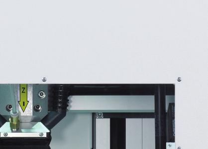
14 4.1.1 Machine Front Buttons: Power, Cover, Stop, Start 2 Milling chamber 3 Protective cover 4 Emergency off switch 5 Legs at base 13


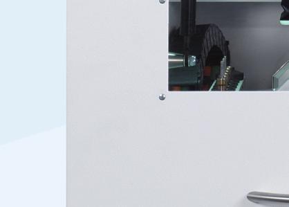
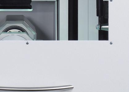
15 4.1.2 Right Side of Machine Connector for suction installation 2 Pressurized air for maintenance unit 3 Pressurized air connector for suction 4 Service flap Y axis 5 Connector panel Connector Panel 1 CAN connection 2 Connector for suction installation 3 Power connector
16 4.1.4 Suction Installation Attention: A suction installation is necessary for the operation of the milling machine. Always use the original TBH suction installation (Type FP150), since this model is designed to conform to the machine's requirements. The use of any other suction installations requires prior approval by WIELAND. The suction component must be directly connected to the ZENOTEC easy with a controller cable. Connect the furnished controller cable to the 9-poled Sub-D plug (Connector 2). Only connect the original cables to the suction component's controller connector. Never touch the machine's plug contact when no controller cable is connected. The mode at which the machine is set may be associated with voltage levels which pose a contact hazard Power Connector The power connector serves as a separator. Only use the furnished connector cables! The machine may only be connected to an isolated ground receptacle, since the protective conductor is connected via the power connector line. 15
 2 Adjustment valve for incoming pressurized air (>6-9 bar) 3 Pressure indicator 4 Pressurized-air connector 5 Separator container 6 Drain valve 7 Pressurized-air outlet for extraction 4.")
17 4.1.6 Pressurized-Air Connector 1 Minimum-pressure monitoring module (5.8 bar) 2 Adjustment valve for incoming pressurized air (>6-9 bar) 3 Pressure indicator 4 Pressurized-air connector 5 Separator container 6 Drain valve 7 Pressurized-air outlet for extraction 4.2 High-Frequency Spindle To warrant a long useful life for the high-frequency spindle, the following guidelines must be observed in the course of handling: Always take precautions and perform work thoroughly. Any application of force (such as strokes, impacts, excess pressure on the shaft or forcible clamping) must be avoided, since these would diminish the precision and useful life of the spindle. For further details, please refer to the separatelyfurnished operation instructions. Ball bearings: The spindle's hybrid ball bearing is equipped with a greasing fixture to ensure a long useful life; this feature renders it maintenance-free. 16
18 4.3 Startup Unpacking and Set-up Attention! Heavy milling device. During the transport of the milling device, there is a risk of crush injuries and damage to the device. The transport of the milling device may only be performed using suitable aids (i.e., elevating platform trucks). The hoisting of the device must be performed by the help of elevating devices or by minimum four people. In this process, always wear safety gloves. 1. Remove the packaging. If possible, keep the packaging material for possible use in a subsequent transport. 2. Ensure that all parts indicated in the given scope of supply are in fact included in the delivery package. 3. Check the delivery for any transport damage. Issue any complaints immediately. 4. Transport the milling device to the designated set-up site Requirements for the Set-up Site The set-up site must meet the following requirements, Technical Data and Ambient Conditions: Set the milling device onto a dry, level and firm surface. This surface must have sufficient load capacity to hold the weight of the milling device. This surface must also be sufficiently stable to compensate the vibrations emanating from the milling device. The ventilation openings on the milling device must remain unobstructed to warrant cooling air circulation. Two mains outlets and a pressurized-air connector must be located near the device and be freely accessible. In the event of relocation (for instance, also after moving the device), the calibration must be checked Set-up and Initial Operation Set-up and initial operation are performed solely by duly authorized specialist personnel. 17
19 5 Operation Please note: When operating the milling device, always observe the guidelines Safety. The milling device is operated via the controls on the machine, as well as by the activation of the machine via the furnished controller PC with the corresponding controller software. 5.1 Switching On and Shutting Off the Machine Switching On Attention: Prior to starting the software, the machine must be switched on! Switch the milling machine on: The main switch on the milling device is located on the rear right-hand side of the milling device. After the machine is switched on, the controller for the milling device is booted up; this can take up to one minute. Switch the controller PC on: The main switch on the controller PC is located at the device. After the controller PC of the milling device is switched on, it is booted up; this can take up to one minute. Switch the monitor on: The monitor's main switch is located on the front of the device. Shutoff The device is shut off with the same switches that it is switched on. When the controller PC is shut off, the monitor automatically switches to Standby mode. To avoid loss of data, it is recommended to close the software before shutting off the machine. 5.2 Referencing the Machine Please note: With each start of the controller software ZENOTEC easy, the machine must be referenced. No movements can be performed with the machine if it has not yet been initialized! Referencing Process: 1. After the control PC is started, start the controller software ZENOTEC easy. If the software does not start, you can start it by double-clicking the icon. 2. The initialization process between the control PC and the machine begins. 18


20 3. During the initialization process, you will be prompted to switch the output stages on. Press the Power button on the front of the milling device. Please note: If the Power button on the machine was pressed beforehand, this message does not appear. 4. Then, you will be prompted to execute a reference run. Confirm this message by checking the box. Without a reference run, no milling program can be started. Please note: Before confirming this message, check the interior of the milling device. No loose objects may be in the interior of the machine which could possible block the movement of the axes! 5. Following this confirmation, the milling device performs referencing for all axes. Following the successful conclusion of the reference run, the machine is in the home position and ready to operate. 5.3 Function of the Controls on the Machine The machine is activated with software, via the furnished controller PC. However, some of the basic operation buttons are located directly on the machine itself Operation Mode Automatic When the protective cover is closed, the machine is in the operation mode Automatic. Only in this operation mode can the actuators and milling spindle be activated. When the protective cover is open, the actuators and milling spindle are electronically blocked. A program start can only be performed with the protective cover closed. 19

21 If a movement command is nevertheless initiated while the protective cover is open, a window with the protective-cover symbol appears along with a prompt to close the cover. Closing the cover also closes the prompt window, and the movement command is started Operation Mode Set-up Attention! When the protective cover is open, the machine is in the operation mode Set-up. The operation mode Set-up is used for equipping the machine with material and milling tools or for cleaning. The protective cover can be opened in any axis position when all actuators are shut off. To open, hold the Cover button down and open the cover. The actuators and the milling spindle cannot be activated in this operation mode! If an attempt is made to activate an actuator or start the machine when the protective cover is open, the power supply to the installation's output stages is immediately interrupted, and a corresponding error message appears. Always observe the safety tips! Cover: If the button is lit, the cover can be opened by pressing the button. The cover can only be opened when all actuators are shut off. Power: With this button, the output electronics module for the actuators is switched on, as long as the conditions indicated by all safety-relevant features on the machine are fulfilled. When you start the control software ZENOTEC easy, you will be prompted to switch the Power button on. 20


22 Emergency off switch: With this button, you can bring the machine to a halt as quick as possible. All actuators will be shut off without delay. To unlock this button, turn it slightly to the right so that it returns to its default position. The emergency off switch must always remain unobstructed and freely accessible. Please observe the safety tips. When you initiate a movement command while the emergency off switch is pressed, the following error message appears: and then: Do not unlock the emergency off switch until you are prompted to do so by the menu window. Start: The Start button is used to start a milling program. A corresponding milling program can then be selected on the software interface. If a milling program is already selected, the machine directly starts processing. Stop: The Stop button interrupts a milling program in progress. If the Stop button is pressed once, the work in progress with the current milling program stops on the current position. If the Start button is then pressed, the machine continues the work in progress with the current milling program. If the Stop button is pressed two times, the milling device stops the work in progress and automatically returns to the home position. 21


23 5.4 Structure of the Control Software Overview Illustration Function Buttons 1 Controller reset This button exits the software and resets the controller. Then, the ZENOTEC easy software must be re-started. To re-start the software, double-click the shortcut on the Desktop ZENOTEC easy. 22

24 2 Transmission of milling files With the aid of this button, the milling files will be transferred from CAM and moves to the folder C:/NC_Daten/Zenotec easy. 3 Open milling program Then, select the program to be milled. The subfolder Archiv contains the milling files which have been moved via the function Archive milling files 4 Archive milling files This button moves all files from the ZENOTEC easy folder to the archive folder. 5 Execute a reference run When this button is pressed, the machine performs a reference run for all axes. After the reference run, the machine is in the home position. 6 Move to service position When the button Service function is pressed, the milling cutter is deposited to the assigned tool place and the Y axis positioned with the open collet in the midpoint across the work piece holding device. The following dialog window appears: 23

25 This function is suitable for: being able to clean the collet when it is freely accessible being able to replace the splash guard depositing a milling cutter already in the collet for replacement positioning the air blast nozzle After the selection and confirmation of a tool place, the corresponding tool is accepted into the collet and measured. 7 Move to cleaning position With this button, the X axis is moved to the rear in order to enable cleaning under the X axis. 8 Suction on/off When the suction component (along with a control cable) is connected to the device, you can manually switch the suction on and off with this button for cleaning. In Automatic mode, the suction is automatically switched on and off. 9 Program START With this button, you start a selected milling program. If a program has not yet been selected, you can access the menu Open milling program with this button, in which you can select the corresponding milling program to be run. 10 Program STOP With this button, you stop a currently-running milling program. The machine then returns to the home position. 24

 has been lodged, this error can cause severe damaged to the milling cutters, the material or the device itself!")
26 5.4.3 Tool Fields To enable the proper access by the milling device to the tools, all tools positioned on tool places must be mapped on the software interface. This is the only way to ensure that the milling machine uses the correct tools for performing work. Caution: The software does not verify whether the milling cutters registered in the tool fields are also in fact placed in the device. If no milling-cutter type (or the wrong type) has been lodged, this error can cause severe damaged to the milling cutters, the material or the device itself! The mapping of the tools in the software takes place via the tool fields, which indicate the following functions: 1 Tool place number (symbol: tool holder) Displays the tool place number. 2 Collet (symbol: collet) This symbol shows the tool which is currently in the milling-spindle. The tool field for the currentlyclamped tool also features a blue background. 3 Tool type (symbol: milling cutter) This field displays the tool type for the respectively used tool. 4 Information field (symbol: i) In this display field, information such as, i.e., milling-cutter length, life time, etc., is displayed via the assigned milling cutter. If no milling cutter has been lodged, the indicated milling-cutter type is indicated as???. When a new milling cutter is registered in the system, the previous cutter length is automatically deleted and a yellow warning symbol appears. This symbol merely indicates that the cutter length is unknown. 25

27 If a value outside of the designated limits is determined during the measurement of the milling cutter (e.g., after breakage of a milling cutter), a red warning triangle appears. This symbol is also displayed in the tool field instead of the symbol tool holder. 5 Units (symbol: tooth with tally) This field displays the number of restoration units which can still be processed with this milling cutter. This value is calculated arithmetically from the remaining life time for the milling cutter and should give an impression of whether one can still work with the given milling cutter. The calculation is based on an average unit size. During each use of the milling cutter, its actual life time is gauged and deducted from the remaining life time. This means that due to differing life times for individual restoration jobs, errors in estimation of the unit calculation may occur. For the display value?, no value is available i.e., because no tool type was assigned. If no more units are available on the milling cutter, the number 0 is displayed. 6 Edit tool field (symbol: cog wheel with milling cutter) To edit tool fields, this button must be pressed. The function is not active when the milling cutter is deposited in the collet. 7 Unit indicator (display as bar) The tool's wear is visually indicated with the aid of the bar display. If only approx. 10% of the total units are still available, the bar changes color from green to red Register Tools to the Software After pressing the button Edit tool field, the following template appears: 1 Tool type (symbol: milling cutter) 26

28 In this field, the tool type (milling-cutter type) is assigned to the corresponding tool place. Each tool type can only be registered once. If an attempt is made to register a given tool type to an additional place, the following error message appears: Please note: The tool field to which the milling cutter is already registered appears highlighted in yellow. 2 Delete (symbol: red x) This command deletes the value from the field Tool type. 3 Tool type list The registration of a milling-cutter type to the field Tool type can also be performed by selecting a suitable milling cutter from the given list. Here, you will also find additional information on the various milling-cutter types: 4 Remaining life time (symbol: milling cutter with clock highlighted in green) The remaining life time corresponds to the interval up to which a milling cutter can operate without quality losses. Overshooting this value can lead to an increase in quality deficiencies during the milling process (i.e., chipping of Zirconia). Following the entry to the field Tool type, the last remaining life time saved for the given tool is automatically assigned to the field Remaining life time. It is possible to change this specification by overwriting the existing value with a new value. However, the input of a value which exceeds the maximum life time for a given milling-cutter type is not possible. In this case, an automatic limitation to the maximum life time for the given milling-cutter type takes place. When using several milling cutters of the same type, we recommend that you note the value for the remaining life time. 27
29 5 Reset remaining life time (symbol: clock highlighted in red) The Clock button reflects the maximum lodged life time for a given tool in the field Remaining life time. With this function, the remaining life time for a new milling cutter can be set to the maximum value. 6 Units (symbol: tooth with tally) This field displays the number of restoration units which can still be processed with the milling cutter. 7 Unit indicator (display as bar) The tool's wear is visually indicated with the aid of the bar display. If only approx. 10% of the total units are still available, the bar changes color from green to red Information Toolbar 1 Current axis positions Displays the current axis position. 2 Spindle RPM Displays the current spindle RPM. 3 Progress indicator Displays (in %) the progression of an already-started milling program. 4 Running time Displays the current running time for the given milling program. 5 Tool information Displays the tool currently in the collet, along with its virtual length. 28
. Then, attach them with six screws.")

30 5.5 Operation of the Milling Unit Insertion and Removal of a Blanc Insertion or removal of a blanc: open the protective cover of the machine. Insert the blanc in the fitting position (into the blanc holder). Then, attach them with six screws. Always ensure that the blanc is securely fastened. Remove all loose tools or objects from the interior of the machine and close the protective cover Tool places The tool places are numbered as shown in the above picture. A total of 5 tool places are available. The tool-length gauge button is located above tool place 1. 29

31 5.5.3 Tool change After the elapse of a pre-defined work interval, the milling tools are worn and must be replaced. Replacement is also required in the event of tool breakage. In general, tools are always replaced in the tool magazine. Attention! To be able to replace a tool, you must be familiar with the basic operation of the machine and its control software. This may only be performed by those who have been accordingly briefed on the machine's operation. If a malfunction occurs when replacing tools and it is unclear which tool is currently in the collet, the following error message appears: By entering the respective tool place and confirming this entry, the tool change can be concluded. If there is no tool in the collet, enter 0 as the tool place. Always observe the safety tips! 30
32 5.5.4 Equipping the Milling Device with New Tools In general, tools are always replaced in the tool magazine. The milling device can be equipped with a maximum of 5 tools. Any tool type can by assigned to any tool place. Insertion or removal of tools: open the protective cover on the machine. Place the tools with rings attached into the tool places with their blades facing downward. During the insertion or removal of tools, always ensure that you do not strike or damage them. Set tools to their positions with the corresponding fixation ring until it catches. Always ensure that the tools are in their proper positions. If a tool to be replaced is in the collet, the milling cutter can be deposited to its tool place with the aid of the service function and removed from there Replacing a Broken Milling Cutter After a tool is accepted into the collet, it is measured for length. In this process, the length of the tool must lie within the range specified for this milling-cutter type. Before a tool is deposited, it is likewise measured once again. If any deviation is detected in the course of this measurement, the following error message appears: Following the confirmation of the error message with the button OK, the broken milling cutter can be deposited and replaced via the service position. The pertinent tool field displays a red warning triangle instead of the tool place symbol so that defect tools can be identified more easily. This warning does not disappear until the milling cutter has been replaced and the milling socket has been released by the software. A milling process which may have been interrupted must be re-started from the beginning. 31
33 5.6 Milling Please familiarize yourself with the specifications before starting a milling program. Please observe the safety tips. Ensure that the machine has been referenced. Insert a blanc into the corresponding holder and attach the blanc sufficiently. Ensure that all necessary milling tools are already in the tool changer. Close the protective cover. Select the desired milling program with the menu option Open milling program. To identify the milling files: In the course of data processing in CAM, a file with the ending.iso is generated (among others). This file contains all data necessary for performing milling work on the ZENOTEC easy. For definite identification, the filename contents the blanc-name with the number of the milling-job. After the START button is pressed, the selected milling-program cycle starts. As an alternative, the milling program can also be started by pressing the Start button on the door. 32
34 6 Maintenance and Care Please note: Regular maintenance and care maintain the machine's operational safety and increase its useful life. Shut off the machine prior to any cleaning and maintenance work which does not require specific items (service item or cleaning item). Pull the mains plug to prevent accidental activation. Attention! Even when the main switch is switched off, some parts of the electrical system are still live. Please wait a few minutes before starting maintenance work. Always observe the safety tips! 6.1 Cleaning Agents To clean the machine, use a moist cloth and, if necessary, a suitable cleaning agent. Never use scouring agents! Cleaning agents which damage plastics, rubber or paint may not be used. Theses can damage hoses (in pneumatics) as well as cables and seals. Cleaning agents may contain substances which are health hazards. Please always observe the manufacturers' indications. 6.2 Electrical Components WARNING! Danger to life from electrocution! All work on the electrical components (such as the connection to the mains as well as maintenance and repairs) may only be performed by qualified specialist personnel. Even when the main switch is switched off, some parts of the electrical system are still live. 6.3 Pneumatics Please note: All work performed on the pneumatics installation (such as initial operation, maintenance and repairs) may only be performed by qualified specialist personnel. Prior to performing any work on the pneumatics installation, the system must be shut off and de-pressurized. 33
35 6.4 Maintenance Booklet for the ZENOTEC easy General Cleanliness Cleanliness lengthens the useful life of the individual components and prevents malfunctions. Therefore, clean the machine regularly with a vacuum cleaner. In the process, ensure that no dirt reaches the machine's mechanical parts. Clean the plastic discs and surfaces with a suitable liquid cleaning agent. Cleaning with pressurized air is not permitted, since fine dust can enter the mechanical parts of the installation and damage them Blanc-Fixtures Dust and chippings must always be removed from the blanc-fixtures and clamping rings before a blanc is inserted to ensure optimum clamping. We recommend the use of a suitable brush for this purpose. Keep the screws and screw threads clean at all times Tool-Fixtures and Length-Gauging Button Tool-fixtures and length-gauging button must likewise be cleaned to remove dust and chippings; this guarantees a trouble-free working of the device. Defective or work tool holders must be replaced. In this case, please contact the service department Spindle Attention! Never spray any sprayable oils, liquids or pressurized air directly onto the spindle-nose, since moisture or dirt can enter the mechanical parts up to the bearings. The spindle nose and the inserted tools must be clean. Impurities and the increased centripetal force which ensues as a result place a great deal of strain on the spindle bearings Collet For cleaning and maintaining the collet, use the furnished collet-maintenance set. 34

36 The collet-maintenance set contains the following: Cleaning brush 2 Ejector rod 3 Screw-attachment part 4 Felt cone 5 Gripper grease The collet must be removed and cleaned at least once a week, as well as after each incidence of tool breakage. It also must be checked for possible damage. Important: Never close the collet without a tool inserted! If the spindle rotates without a tool, it may be destroyed as a result! Proper procedure for cleaning: Move the spindle to the Service position. Ensure that the shaft is not rotating. Open the collet with the button Service position. With the screw-attachment part (3), unscrew the collet from the shaft. Then, clean the cone in the shaft with the designated felt cone (4). Clean the collet with the designated brush (1). Ensure that there is no more dirt in the collet and that no dirt is transferred to the collect in the course of cleaning. If a tool should break off and a remnant remains stuck in the collet, you can remove it with the aid of the ejector rod (2). Apply a light grease film (gripper grease (5)) to the exterior cone of the collet. Then, manually screw the collet back into the spindle. The collet must be screwed in until it catches (hand-tight). If the collet cannot be manually screwed back until it catches, please use the screw-attachment part (3). End the service position. Then, the spindle is ready. 35
37 Caution: Extensive skin contact with the gripper grease can lead to skin irritation and/or dermatitis. The following precautions are recommended: Avoid extensive and intense skin contact. After completing work and prior to taking breaks, make sure to clean your skin thoroughly. Preventive skin protection by the use of protective agents is recommended. A safety data sheet for the gripper grease can be obtained from WIELAND Positioning the Cleaning Pipe To achieve the most effective cleaning process, the cleaning pipe must be positioned towards the milling-cutter tip. Insert the ejection rod (2) into the pipe and move the pipe so that the ejector rod touches the milling-cutter tip in order to position the pipe. Then, remove the ejector rod once again Water Separator Attention! On the right side of the machine, there is a water separator. This device extracts the remaining moisture from the pressurized air. However, the condition for its proper operation is the use of clean, dry and oil-free pressurized air. If nevertheless water accumulates in the inspection window, there is a drainage screw below the inspection window. By turning this screw, you can empty the water separator. The water separator must be checked at least once daily and emptied if necessary. If impurities occur, always have the pressurized-air supply checked! Guide Rails and Motor Shafts The guide rails and motor shafts require little maintenance and are equipped with a long-term lubrication fixture. These are, if necessary, re-greased in the context of maintenance work performed by specialist personnel from WIELAND. 36
38 6.4.9 Control Calibration Body To test the accuracy of the milling machine, you should mill one calibration body per month. Send the calibration body to the WIELAND Service Team for evaluation. If positioning system adjustments are necessary, these will be completed through the remote maintenance system by WIELAND Regular Maintenance Maintenance Checklist Prior to each start of the machine Daily maintenance Weekly maintenance or after a tool failure Clean the acceptance of blanks, tool acceptances, tool shaft for all tools and length-gauging button. Check the water separator and empty if necessary. If impurities occur, always check the pressurized-air supply! Remove the collet, then clean it and check for damage; also grease the cone. Clean the collet acceptor with the furnished felt cone. 37
39 7 Faults and Error Messages Error Possible cause Possible solution The unit cannot be turned on The POWER button does not work Reference run not performed properly The propulsion engine is not responding Cover cannot be opened Power connector not available The main switch is not switched on The machine is not turned on The cover is not closed Emergency off has been pressed Power is not switched on Cover is not properly closed Communication error Connection between the machine and the controller PC is interrupted No voltage supply to output stage The cover is not closed An axis is in motion. The spindle is rotating Plug in the mains plug Turn on the main switch Switch on the machine Close the cover Unlock emergency off Switch on Power Close cover properly Shut off the machine and shut down the control computer's operating system. Then, wait 30 sec before once again switching the machine and PC on. Close the protective cover. Switch on Power. Re-start the control software Check the connection and reestablish it as necessary Re-start the control software. Switch the output stages on with the POWER button. Close the cover and re-start the control software Wait until the program cycle has ended. End the program cycle manually Collet cannot be opened Pressurized air supply too low Check pressurized air level (min. 6 bar) The spindle does not work No clearance by the software Re-start software and try again The cover is not closed Close the cover 38


40 7.1 Error Messages in ZENOTEC easy Possible cause: Control software started when the machine is shut off No communication between the machine and the controller PC Solution: Close the control software, switch the machine on, re-start the control software and follow the dialogue on the screen Check the connector line between the controller PC and the machine Possible cause: Control software started when the machine is shut off Solution: Close the control software, switch the machine on, re-start the control software and follow the dialogue on the screen 39
41 No communication between the machine and the controller PC Check the connector line between the controller PC and the machine Possible cause: Control software started when the machine is shut off No communication between the machine and the controller PC Solution: Close the control software, switch the machine on, re-start the control software and follow the dialogue on the screen Check the connector line between the controller PC and the machine 40
42 Possible cause: Control software started, Power not switched on Attempt to perform a movement process when cover is open Communication error during a movement process Solution: Close the control software, switch the machine on, re-start the control software and follow the dialogue on the screen Close the cover Close and re-start the software 41
43 Possible cause: EMERGENCY OFF has been pressed Control software started, Power not switched on Attempt to perform a movement process when cover is open Communication error during a movement process Solution: Unlock the EMERGENCY OFF and, if necessary, re-start the software Close the control software, switch the machine on, re-start the control software and follow the dialogue on the screen Close the cover Close and re-start the software Possible cause: EMERGENCY OFF activated while program is running Interruption in the power supply to the output stages Solution: Unlock the EMERGENCY OFF and, if necessary, re-start the software Close the control software, switch the machine on, re-start the control software and follow the dialogue on the screen 42
44 Possible cause: Cover open at program start Safety circuit activated Solution: Close cover, perform reference run, re-start program Check to see whether the cover is properly closed, Power is set to ON and the EMERGENCY OFF is unlocked. Restart the software. Possible cause: Communication error between the controller PC and the machine's output stages Solution: Check the connector cable between the controller PC and the machine. Restart the control software. 43
45 Possible cause: Solution: Tool length irregularity, tool too short Move the machine to the service position. Check the following items: - the affected tool for the possibility of breakage or attachment of the wrong ring, - the possibility of having attached the wrong tool. - Check and clean the collet. Possible cause: Solution: Tool length irregularity, tool too long Move the machine to the service position. Check the following items: - the affected tool for the possibility of breakage or attachment of the wrong ring, - the possibility of having attached the wrong tool. - Check the proper position of the collet and clean it. 44

46 Possible cause: Pressurized air supply too low Solution: Check the machine's initial pressure level. The machine continues the ongoing process as soon as sufficient pressure is introduced Please contact the WIELAND Service Team for assistance or information if other faults occur. 45
47 8 Return of Old Electric and Electronic Equipment for Disposal 1. Collection Users of electric and electronic equipment are required to collect their old equipment separately from other waste in accordance with the regulations of the specific country. Old electric and electronic equipment must not be disposed of with unsorted household waste. This separate collection is a prerequisite for recycling and reprocessing as an important method for preserving environmental resources. 2. Return and Collection Systems When your ZENOTEC easy is no longer usable, do not dispose of the device with household waste. WIELAND has set up special disposal facilities to handle the equipment. For details please contact WIELAND. 3. Meaning of the Symbols The EU Directive prohibits the disposal of any electric or electronic devices marked with these symbols in combination with household waste. 46
48 9 Customer Information No person is authorized to provide any information that deviates from the information provided in this instruction sheet. 9.1 Warranty IMES-ICORE warrants this product will be free from defects in material and manufacture. IMES- ICORE MAKES NO OTHER WARRANTIES INCLUDING ANY IMPLIED WARRANTY OF MERCHANTABILITY OR FITNESS FOR A PARTICULAR PURPOSE. User is responsible for determining the suitability of the product for user s application. If this product is defective within the warranty period, your exclusive remedy and IMES-ICORE s sole obligation shall be repair or replacement of the IMES-ICORE product. 9.2 Limitation of Liability Except where prohibited by law, IMES-ICORE will not be liable for any loss or damage arising from this product, whether direct, indirect, special, incidental or consequential, regardless of the theory asserted, including warranty, contract, negligence or strict liability. Information valid as of August
Lava CNC 240. Milling Machine for Partially-Sintered Ceramic Products and Plastics by 3M ESPE. Original Operating Instructions
 Lava CNC 240 Milling Machine for Partially-Sintered Ceramic Products and Plastics by 3M ESPE Original Operating Instructions 3M ESPE AG Dental Products D-82229 Seefeld - Germany 3M ESPE Dental Products
Operator s Manual. IP-100 Immersion Probe Cooler
 Operator s Manual IP-100 Immersion Probe Cooler 110-810 04.27.11 Table of Contents Introduction... 3 General Information... 3 General Safety Information... 3 Safety Recommendations... 4 Unpacking Your
Millo / Millo pro. Nr x000 / 1805-x000. Ideen für die Dentaltechnik A
 Millo / Millo pro Nr. 1804-x000 / 1805-x000 0609 21-6543 A Ideen für die Dentaltechnik 1 2 3 4 5 6 7 8 9 10 11 12 Millo / Millo pro No. 1804-x000 / 1805-x000 ENGLISH Content Introduction... 15 Symbols...
User Manual GV25 GV35 GV702. Company information: Original instructions GV12066 (1)
") User Manual Original instructions GV25 GV35 GV702 Company information: www.vipercleaning.eu info-eu@vipercleaning.com GV12066 (1) 2012-04-10 USER MANUAL ENGLISH TABLE OF CONTENTS Introduction... 4 Manual
User Manual Original instructions GV25 GV35 GV702 Company information: www.vipercleaning.eu info-eu@vipercleaning.com GV12066 (1) 2012-04-10 USER MANUAL ENGLISH TABLE OF CONTENTS Introduction... 4 Manual
Installation and Operating Instructions DÜRR Regeneration Unit for X-ray developers XR 24, XR24 II, XR 24 Nova, XR 24 Pro
 Installation and Operating Instructions DÜRR Regeneration Unit for X-ray developers XR 24, XR24 II, XR 24 Nova, XR 24 Pro 2006/01 Content Important Information 1. Notes... 3 1.1 CE - Labeling... 3 1.2
Thank You & Congratulations On Your Purchase of: ARBE Model # SS-206 Table Top Dust Collector
 Thank You & Congratulations On Your Purchase of: ARBE Model # SS-206 Table Top Dust Collector "The Most Powerful Dust Collector In Its Class... Guaranteed!" IMPORTANT INSTRUCTIONS DO NOT DISCARD I Thank
Cercon brain expert Instructions for use. Cercon smart ceramics the zirconium oxide full ceramic system
 Cercon brain expert Instructions for use Cercon smart ceramics the zirconium oxide full ceramic system These operating instructions help you to use the Cercon brain expert, briefly referred to as the device,
Instruction Manual Hydraulic Crimping Tool
 Instruction Manual Hydraulic Crimping Tool 902-480 Due to continuing improvements, actual product may differ slightly from the product described herein. Read this material before using this product. Failure
CEREC MC XL Premium Package / MC XL / MC X / MC and inlab MC XL. Cleaning and Maintenance
 CEREC MC XL Premium Package / MC XL / MC X / MC and inlab MC XL Cleaning and Maintenance Contents 03 04 04 05 06 07 07 07 08 08 09 09 09 09 10 12 15 Maintenance Schedule Water System Changing the Filter
EN Z Subject to change due to technical improvements! Operating instructions
 SOLARTHERMIE - SOLAR THERMAL - SOLAR TÉRMICO - SOLAIRE THERMIQUE Operating instructions Temperature differential controller 3 inputs, 1 output These operating instructions are part of the product. Read
Industrial Vacuums, Inc
 Instructions/Spare Parts Manual Nilfisk Model GWD255 Drum Top Vacuum CAUTION: This Nilfisk vacuum cleaner is not to be used in explosion-hazardous areas, as serious injury could result. Under no circumstances
Trotec PAC FT 2600 Portable air conditioner
 Trotec PAC FT 2600 Portable air conditioner The PAC FT 2600 portable room air conditioner comes with an infrared remote control and an air outlet hose with a flat nozzle.the unit s primary function is
TTV 1500 / TTV 3000 OPERATING MANUAL CONVEYING FAN TRT-BA-TTV TC EN
 TTV 1500 / TTV 3000 EN OPERATING MANUAL CONVEYING FAN TRT-BA-TTV1500-3000-TC2016-26-004-EN Table of contents Notes regarding the operating manual... 2 You can download the current version of the operating
Operating and Maintenance Instructions
 EATON Germany GmbH Werk Lohmar D-53797 Lohmar Operating and Maintenance Instructions WALFORM Machine Electronically controlled - Conforms to CE MEG-WF385X Status: Sept 2011 MEG-WF385X_Stand Sept 2011 SUITABILITY
Operation Manual Vortex mixer unitexer 1
 Operation Manual Vortex mixer unitexer 1 CONTENTS 1. Introduction...1 2. Intended Use...1 3. Features...1 4. Standard Part Listing...1 5. Safety Precautions... 2 6. Operation... 2 7. Technical Specification...
Operator s Manual. Histology Bath
 Operator s Manual Histology Bath 110-827 05.09.12 Table of Contents Introduction... 2 General Safety Information... 2 Safety Recommendations... 3 Unpacking Your Histology Bath...4 Contents...4 Components
Air Pump Up to 800 gallons
 Air Pump Up to 800 gallons REMINDER CALL 1-888-755-6750 BEFORE RETURNING TO STORE. PACKAGE CONTENTS ITEM #PBPAPK40W Questions, problems, missing parts? Before returning to your retailer, call our customer
SILENT compact /
 SILT compact 2934 0000 / 2934 1000 TRANSLATION OF THE ORIGINAL INSTRUCTIONS FOR USE Made in Germany Ideas for dental technology 21-2245 21052015 / A Contents 1. Introduction...3 1.1 Symbols...3 2. Safety...3
High Output Vacuum/Pressure Pump
 High Output Vacuum/Pressure Pump User Guide Catalogue Numbers: WP62 115 60 (115 V, 60 Hz) WP62 220 50 (230 V, 50 Hz, 1.1 A) WP62 100 60 (100 V, 50/60 Hz) Notice The information in this document is subject
Installation and assembly instructions. for standard configuration radial blowers
 Installation and assembly instructions for standard configuration radial blowers 001_KL01_01 Printed in Germany We reserve the right to change the information and illustrations shown in this operating
Installation and operating instructions. Temperature difference controller 6 inputs, 3 outputs, integrated data logger for SD card
 SOLARTHERMIE - SOLAR THERMAL - SOLAR TÉRMICO - SOLAIRE THERMIQUE - SOLARE TERMICO Installation and operating instructions Temperature difference controller 6 inputs, 3 outputs, integrated data logger for
Combivac Operating Instructions Combivac
 Combivac 17-36 Operating Instructions Combivac General Table of contents General...2 Table of contents...2 Information about the operating instructions...3 Liability...3 Notices in the operating instructions...3
GRUNDFOS INSTRUCTIONS. Sololift2 C-3. Installation and operating instructions
 GRUNDFOS INSTRUCTIONS Sololift2 C-3 Installation and operating instructions English (US) English (US) Installation and operating instructions Original installation and operating instructions. CONTENTS
Original operating instructions Safety switch with guard locking AC901S AC902S
 Original operating instructions Safety switch with guard locking AC901S AC902S 7390914/03 01/2017 Contents 1 Preliminary note...4 1.1 Explanation of symbols...4 2 Safety instructions...4 3 Items supplied...5
HW-17 Record Cleaning Machine Setup and Instruction Manual
 HW-17 Record Cleaning Machine Setup and Instruction Manual VPI Industries, Inc., 77 Cliffwood Ave. #3B, Cliffwood, NJ 07721 Phone: 732-583-6895, Email: Sales@vpiindustries.com http://www.vpiindustries.com
OPERATING MANUAL. for the modular heat presses. Secabo TC5 SMART and TC7 SMART
 OPERATING MANUAL for the modular heat presses Secabo TC5 SMART and TC7 SMART Congratulations on the purchase of your Secabo heat press! Please read this operating manual carefully to ensure a smooth production
H-16.5 Record Cleaning Machine Setup and Instruction Manual
 H-16.5 Record Cleaning Machine Setup and Instruction Manual VPI INDUSTRIES, INC., 77 CLIFFWOOD AVE., #3B, CLIFFWOOD, NJ 07721 PHONE: 1-732-583-6895, FAX: 1-732-946-8578 http://www.vpiindustries.com 1 Table
Alarm System SECURE AS 302
 Alarm System SECURE AS 302 Operating Manual SECURE Light app now available! Table of Contents Before You Start.................................. 4 User Information....................................4
USER S MANUAL ATH WH220
 USER S MANUAL ATH WH220 INDEX INTRODUCTION... - 3 - General information s... - 3 - Description of pneumatic jack... - 4 - Operation of jack... - 5 - Technical data... - 6 - Dimension drawing... - 6 - INSTALLATION...
Compressed-air grinder. AirMAX 230F. Instruction manual
 Compressed-air grinder AirMAX 230F Instruction manual 1 List of Contents 1 List of contents... Page 02 2 Tips on using the manual... Page 03 3 Safety instructions... Page 04 4 Warranty/Identification...
CENTRIFUGAL FAN IN SCROLL CASING. Helix S-Vent OPERATION MANUAL
 CENTRIFUGAL FAN IN SCROLL CASING Helix S-Vent EN OPERATION MANUAL Helix / S-Vent www.blaubergventilatoren.de CONTENTS CONTENTS 3 Introduction 3 Use 3 Delivery set 4 Technical data 10 Safety requirements
USER S MANUAL. VCU/VCUN Series CENTRIFUGAL FAN IN SCROLL CASING
 USER S MANUAL VCU/ Series CENTRIFUGAL FAN IN SCROLL CASING 2 CONTENTS Introduction Use Delivery set Designation key Technical data Safety requirements Design and operating logic Mounting and set-up Connection
User instructions. VA20HD, VA55HD, VA55IND and VA75IND. Commercial wet/dry vacuum cleaners CAUTION - READ THESE INSTRUCTIONS BEFORE USING THE MACHINE
 User instructions VA20HD, VA55HD, VA55IND and VA75IND Commercial wet/dry vacuum cleaners CAUTION - READ THESE INSTRUCTIONS BEFORE USING THE MACHINE 03-8112-0000 Iss.3 07/08 http://www.truvox.com/products/vacuums/valet_aqua
POLYMIX PX-IG 2000 Operating Instructions
 POLYMIX PX-IG 2000 Operating Instructions Voltage D 100-120V, 50/60 Hz D 210-250V, 50/60 Hz Please check that the voltage is correct and corresponds with the nameplate on the back of the machine. Manual
Zfx. Mill inhouse. User manual
 TM Zfx Mill inhouse User manual 1 Content 1. General Information... 4 1.1 The Manual... 4 1.2 Characteristics of the Machines... 5 1.3 Technical Data... 5 1.3.1 Basic System... 5 1.3.2 Rotary Axis...
INLINE СENTRIFUGAL FAN BOX BOX-R OPERATION MANUAL
 INLINE СENTRIFUGAL FAN BOX BOX-R OPERATION MANUAL CONTENT 3 Introduction 3 General 3 Safety rules 3 Storage and transportation rules 3 Manufacturer s warranty 4 Fan design 4 Delivery set 5 Technical data
JASOPELS ROTATING FLESHING MACHINE 1-BEAM
 USER MANUAL JASOPELS ROTATING FLESHING MACHINE 1-BEAM ITEM NO. 32200067 Our quality Your choice 2 www.jasopels.com TABLE OF CONTENTS About this document... 3 Declaration of Conformity... 6 Safety... 6
SOUND-INSULATED FAN. Iso-K OPERATION MANUAL. Iso-K_v.1(2)-EN.indd :20:59
-EN.indd :20:59") SOUND-INSULATED FAN OPERATION MANUAL _v.1(2)-en.indd 1 10.08.2015 15:20:59 CONTENT Introduction 3 General 3 Safety rules 3 Transport and storage requirements 3 Manufacturer's warranty 3 Fan design 4 Delivery
SOUND-INSULATED FAN OPERATION MANUAL _v.1(2)-en.indd 1 10.08.2015 15:20:59 CONTENT Introduction 3 General 3 Safety rules 3 Transport and storage requirements 3 Manufacturer's warranty 3 Fan design 4 Delivery
20 High velocity Air
 20 High velocity Air Circulator 66878 Set up and Operating Instructions Distributed exclusively by Harbor Freight Tools. 3491 Mission Oaks Blvd., Camarillo, CA 93011 Visit our website at: http://www.harborfreight.com
MODEL 7000 SUCTION UNIT
 MODEL 7000 SUCTION UNIT OPERATOR S MANUAL Caution Federal law restricts this device to sale by or on order of a physician, or any other practitioner licensed by the law of the State in which he practices
NON-CYCLING REFRIGERATED AIR/GAS DRYERS QPNC 75 to QPNC 250 OPERATOR S MANUAL
 NON-CYCLING REFRIGERATED AIR/GAS DRYERS QPNC 75 to QPNC 250 OPERATOR S MANUAL DATE OF PURCHASE: MODEL: SERIAL NO.: Record above information from nameplate. Retain this information for future reference.
STEAM WALLPAPER STRIPPER MODEL HTW5
 STEAM WALLPAPER STRIPPER MODEL HTW5 From Serial Number 75154 (110 Volt North America only) OWNERS MANUAL & OPERATING INSTRUCTIONS 2016/11 Hiretech Part # 007717 WARNING For safe operation of this machine,
Version 1.6. Operating instructions HYDROMETTE BL COMPACT TF 2. Hydromette BL Compact TF 2
 Version 1.6 Operating instructions HYDROETTE BL COPACT TF 2 EN 1 Table of contents 0.1 Publication statement... 3 0.2 General notes... 4 0.3 WEEE directive 2002/96/EC law on electrical and electronic equipment...
Focus 4010\ Focus 4010 HT porcelain firing furnace
 INSTRUCTION MANUAL Focus 4010\ Focus 4010 HT porcelain firing furnace Warning You have available one of the most precise dental furnaces equipped with a heating muffle made by the original manufacturer
CAD/CAM TECHNOLOGY. DC1 Milling System
 CAD/CAM TECHNOLOGY DC1 Milling System Technological lead in the modern compact class! Dental Concept Systems has completed its range with the DC1 and offers a basic device in the compact class of modern
EVAPORATIVE COOLER W
 EVAPORATIVE COOLER 972-1003-W USER MANUAL INTRODUCTION READ AND SAVE THESE INSTRUTIONS! 1 Thanks for your support and choice of our unique tower fan, in order to help you use the product more conveniently,
Illustration shows item no Z Original operating manual. Operating manual. BlueMobil eco. Item no: Z-3278
 Illustration shows item no Z-3278 Operating manual BlueMobil eco Item no: Z-3278 Original operating manual Important Copyright It is essential that you read this manual thoroughly before the initial operation
Pressurized Filter Up to 1250 gallons
 Pressurized Filter Up to 1250 gallons REMINDER CALL 1-888-755-6750 BEFORE RETURNING TO STORE. ITEM #FP1250UV Questions, problems, missing parts? Before returning to your retailer, call our customer service
POWER SWEEP N VAC 1800W Model No. 101BV1800
 POWER SWEEP N VAC 1800W Model No. 101BV1800 Operator s Manual WARNING To reduce the risk of injury, the user must read and understand the Operator s Manual. Save this manual. Introduction Thank you for
USER S MANUAL. Heat Recovery Ventilator. Vents Brig HRV 200 Vents Brig HRV 300
 USER S MANUAL Heat Recovery Ventilator Vents Brig HRV 200 Vents Brig HRV 300 2 Brig HRV 200 (300) CONTENT Introduction... 3 Application... 3 Delivery set... 3 Unit designation key... 4 Basic unit dimensions...
Waste water ejection unit
 Waste water ejection unit Over ground box SWH 500/50-80 SWH 500/50-80 Operation manual Table of contents: Page Declaration of conformity... 3 1. General... 4 1.1 Introduction... 4 1.2 Enquiries and orders...
DELUXE ELECTRIC POWER BRUSH
 DELUXE ELECTRIC POWER BRUSH MODEL: BN200! FOR HOUSEHOLD USE ONLY! AB0008 HOMEOWNERS OPERATING INSTRUCTIONS READ AND SAVE THESE INSTRUCTIONS Broan-NuTone Canada Inc.; Mississauga, Ontario www.broan.ca or
Operating instructions
 SOLARTHERMIE - SOLAR THERMAL - SOLAR TÉRMICO - SOLAIRE THERMIQUE Operating instructions Temperature Differential Controller inputs, 1 output These operating instructions are part of the product. US Read
Operating instructions
 MA00929301 09/2015 Operating instructions ED10429002 ESYLUX GmbH An der Strusbek 40 22926 Ahrensburg Germany info@esylux.com www.esylux.com 1 Table of contents 1 Using the manual 8 2 Safety instructions
INLINE CENTRIFUGAL FAN. Centro-M OPERATION MANUAL
 INLINE CENTRIFUGAL FAN OPERATION MANUAL www.blaubergventilatoren.de CONTENT 3 Introduction 3 General 3 Safety rules 3 Transport and storage requirements 3 Manufacturer's warranty 4 Fan design 4 Delivery
THE MW-1 Cyclone RECORD CLEANING MACHINE
 THE MW-1 Cyclone RECORD CLEANING MACHINE SETUP AND INSTRUCTION MANUAL VPI INDUSTRIES INC., 77 CLIFFWOOD AVE #3B CLIFFWOOD, N.J. 07721 **IMPORTANT***IMPORTANT***IMPORTANT***IMPORTANT** YOUR WARRANTEE MAY
OPERATING AND INSTALLATION MANUAL
 OPERATING AND INSTALLATION MANUAL TANKLESS ELECTRIC WATER HEATER WITH ELECTRO-MECHANICAL FLOW SWITCH» MINI 2» MINI 2.5» MINI 3» MINI 3.5» MINI 4» MINI 6 The Mini series is tested and certified by WQA against
AXIS-QA G TUBO-M/MZ AXIAL FANS. Axis / Tubo OPERATION MANUAL
 TUBO-M/MZ AXIS-QA AXIS-Q TUBO-F AXIS-QR AXIS-F AXIS-QRA AXIS-QA G AXIAL FANS EN OPERATION MANUAL www.blaubergventilatoren.de CONTENT 3 Introduction 3 General 3 Safety rules 3 Transport and storage requirements
K 5.80 M ( ) Caution! Do not use the unit without first having read the operating instructions.
 Caution! Do not use the unit without first having read the operating instructions.") K 5.80 M 5.960-830 (2004330-04-03) Caution! Do not use the unit without first having read the operating instructions. Contents Short instructions... 2 Assembly... 3 Safety Notes... 4 Before first use...
K 5.80 M 5.960-830 (2004330-04-03) Caution! Do not use the unit without first having read the operating instructions. Contents Short instructions... 2 Assembly... 3 Safety Notes... 4 Before first use...
Decentralised ventilation units
 Notes on installation Decentralised ventilation units FSL / SCHOOLAIR GB/en TROX GmbH Heinrich-Trox-Platz 47504 Neukirchen-Vluyn Germany Phone: +49 (0) 2845 2020 Fax: +49 (0) 2845 202265 E-mail: trox@trox.de
Nilfisk Model VHS255 Drum Top Vacuum
 Instructions/Spare Parts Manual Nilfisk Model VHS255 Drum Top Vacuum CAUTION: This Nilfisk vacuum cleaner is not to be used in classified (hazardous) environments, as serious injury could result. Under
Portable Dehumidifier
 Portable Dehumidifier OPERATING INSTRUCTIONS HMT-D30-A Model Numbers: HMT-D30-A HMT-D45E-A HMT-D70E-A HMT-D45E-A HMT-D70E-A 3058080 V.161115 PURCHASE INFORMATION Thank you for choosing a Soleus Air Portable
FSW300 Series Flow Switch
 . FSW300 Series Flow Switch - 2 - Series FSW300 Series FSW300 Table of contents page 0 About this operating manual... 4 1 Device description... 5 1.1 Intended use... 5 1.1.1 Reed contact - Switching of
HD 525 S 06/03 A ! 5.960
 HD 525 S 5 960 845 A2005225 06/03! Please read these operating instructions before starting and strictly observe the Safety Instructions for High Pressure Cleaners (5.951-949). WARNING DO NOT SPRAY ELECTRICAL
Operation Manual. For. Herbicide Sprayer
 Operation Manual For Herbicide Sprayer NIKO GmbH Maschinen- & Fahrzeugbau. Im Mühlgut 1a. D-77815 Bühl-Weitenung Introduction Dear Customer, Thank you for the trust in us you have demonstrated by purchasing
Instruction Manual. Alarm Unit For Low Gas Level # Read manual before use! Observe all safety information! Keep manual for future use!
 Mess-, Regel- und Überwachungsgeräte für Haustechnik, Industrie und Umweltschutz Lindenstraße 20 74363 Güglingen Telefon +49 7135-102-0 Service +49 7135-102-211 Telefax +49 7135-102-147 info@afriso.de
Crimping machine RC AS Operating instructions
 Crimping machine RC AS 4050.456 Operating instructions Contents Contents About this documentation... 4 General safety notes... 5. Intended use... 5. Material that can be processed and crimping shape...
Installation and Operating instructions for. C9900-U battery pack. Version: 2.0 Date:
 Installation and Operating instructions for C9900-U330-0010 battery pack Version: 2.0 Date: 2017-03-23 Table of contents Table of contents 1 Foreword 3 1.1 Notes on the Documentation 3 1.1.1 Liability
Installation & Maintenance Instructions
 IMPORTANT INSTRUCTIONS READ AND SAVE THESE INSTRUCTIONS Saving energy and creating healthy, comfortable environments No. II-450 Date July, 2015 DRIVE-THRU UNIT 3 AIR CURTAIN SERIES DTU03 for outdoor use
USER MANUAL. Version: 1.0. ROBE Show Lighting s.r.o. Czech Republic
 USER MANUAL Version: 1.0 ROBE Show Lighting s.r.o. Czech Republic www.robe.cz Table of contents 1.Introduction 4 2.Cautions 4 3. Unpacking & Inspection 5 4. Setup 5 5. Operation 5 5.1.Control Module Operation
VETO CLEANER 500 FLUE GAS CLEANER
 As of serial number 3100 0001 VETO CLEANER 500 FLUE GAS CLEANER USER MANUAL SPARE PARTS LIST Manufacturer: ALA TALKKARI Veljekset Ala-Talkkari Oy FI-62130 HELLANMAA TEL. +358 6 433 6333 FAX +358 6 437
PORTABLE DEHUMIDIFIER
 PORTABLE DEHUMIDIFIER User s Manual For information or assistance, please contact: Soleus International 9451 Telstar Ave. El Monte, CA 91731 Tel: 1-888-876-5387 www.soleusair.com POWERED BY: KEEP THESE
OPERATING AND INSTALLATION MANUAL
 OPERATING AND INSTALLATION MANUAL TANKLESS ELECTRIC WATER HEATER WITH ELECTRO-MECHANICAL FLOW SWITCH» MINI 2» MINI 2.5» MINI 3» MINI 3.5» MINI 4» MINI 6 The Mini series is tested and certified by WQA against
SSS BPV- 40 Backpack Vacuum
 SSS BPV- 40 Backpack Vacuum Manual The contents of this manual are based on the latest product information available at the time of publication. Triple S reserves the right to make changes or improvements
Cleaning unit for coolant. :_decftez`_>r_fr] Book No.: V2
![Cleaning unit for coolant. :_decftez`_>r_fr] Book No.: V2](/thumbs/90/104143238.jpg "Cleaning unit for coolant. :_decftez`_>r_fr] Book No.: V2") Cleaning unit for coolant :_decftez`_>r_fr] Book No.: 1271526-02 V2 Alfa Laval Separation AB Separator Manuals, dept. SKEL S-147 80 Tumba, Sweden Telephone: +46 8 53 06 50 00 Telefax: +46 8 53 03 10 40
Cleaning unit for coolant :_decftez`_>r_fr] Book No.: 1271526-02 V2 Alfa Laval Separation AB Separator Manuals, dept. SKEL S-147 80 Tumba, Sweden Telephone: +46 8 53 06 50 00 Telefax: +46 8 53 03 10 40
Silent TS. Nr / Ideas for dental technology / A. Made in Germany
 Silent TS Nr. 2921-0050 / 2921-1050 21-9191 30102012 / A Made in Germany Ideas for dental technology 1 2 3 4 5 6 7 8 9 10 11 12 13 14 15 16 17 18 19 20 21 22 23 24 25 26 27 28 29 30 31 Silent TS Nr. 2921-0050
Operating Instructions
 Operating Instructions Varioset Standard After-sales service For after-sales service please contact the Veit representative in your country. GmbH & Co. Justus - von - Liebig - Str. 15 D - 86899 Landsberg
HPS-C-MULTI 6. Hotrunner Controllers. Operating manual. Valid for item numbers:
 Valid for item numbers: HPS-C-MULTI 6: 69010.306 (6-zone) 69010.312 (12-zone) 69010.324 (24-zone) 69010.336 (36-zone) HPS-C-MULTI 6 Hotrunner Controllers Operating manual HPS-C-MULTI 6 with WIRE TEST (WT):
OPERATING INSTRUCTIONS. for the heat press. Secabo TPD7 PREMIUM
 OPERATING INSTRUCTIONS for the heat press Secabo TPD7 PREMIUM Congratulations on the purchase of your Secabo heat press! Please carefully read the operating manual to easily integrate your unit into your
Garment Steamer Model SC620
 OWNER S MANUAL Garment Steamer Model SC620 For information or assistance: EURO-PRO Corporation 178 West Service Rd. Champlain, NY 12919 1-800-798-7398 www.euro-pro.com IMPORTANT SAFETY INSTRUCTIONS When
Reacti-Therm I and III Heating Modules
 INSTRUCTIONS Reacti-Therm I and III Heating Modules TS-18822 TS-18824 Number TS-18822 TS-18824 Description Reacti-Therm I Heating Module (single block) Reacti-Therm III Heating Module (triple block) 2101.1
USER S OPERATING AND INSTRUCTION MANUAL
 Grand Rapids, Michigan, U.S.A. 49504-5298 USER S OPERATING AND INSTRUCTION MANUAL MODEL 1508-NLG SELF-ACTUATING TRAY LIDDER 1508S20000CV2 INDEX SAFETY INSTRUCTIONS... 1508S20002 SET UP... 1508S20003 OPERATING
Operation Manual. Mobile Dustfree Pressure Air Blasting System HSP-20
 Operation Manual Mobile Dustfree Pressure Air Blasting System HSP-20 Clemco International GmbH Carl-Zeiss-Straße 21 Tel.: +49 (0) 8062 90080 83052 Bruckmühl Mail: info@clemco.de Germany Web: www.clemco-international.com
Operating Instructions. Accessory Units Melitta Cafina XT Series. Melitta Professional Coffee Solutions
 Operating Instructions Accessory Units Melitta Cafina XT Series Melitta Professional Coffee Solutions Contents General... 4. Manufacturer information... 4.2 About these instructions... 4.3 Explanation
DELUXE ELECTRIC POWER BRUSH
 DELUXE ELECTRIC POWER BRUSH MODEL: 30635615! FOR HOUSEHOLD USE ONLY! AB0008 HOMEOWNERS OPERATING INSTRUCTIONS READ AND SAVE THESE INSTRUCTIONS Venmar Ventilation ULC, Drummondville, Québec 1-844-670-2334
Model K 520 M Part No
 Model K 520 M Part No. 1.069-680.0 High Pressure Washer Operator Manual Overview... 2 Precautions... 2-4 Assembly Instructions... 4 Operating Instructions... 5 Using the Accessories... 6 Working with Detergents...
Bona DCS70/Portable DCS Manual and safety instruction
 Bona DCS70/Portable DCS Manual and safety instruction WARNING Read the instructions manual before using the machine AMO530002 AMO530005 Bruksanvisning i original v1.1 TECHNICAL DATA Motor type: DCS70 Portable
WET/DRY VACUUM. QUEST for Continuous Improvement Windsor s Quality Management System is Certified ISO MODEL: T1. Operating Instructions (ENG)
") WET/DRY VACUUM Operating Instructions (ENG) MODEL: T1 y QUEST for Continuous Improvement Windsor s Quality Management System is Certified ISO 9001. Read these instructions before operating the machine.
WET/DRY VACUUM Operating Instructions (ENG) MODEL: T1 y QUEST for Continuous Improvement Windsor s Quality Management System is Certified ISO 9001. Read these instructions before operating the machine.
CP-200 Push Button. CP Warewash Pump Instruction & Operation Manual Push Button , Rev1.0,
 CP-200 - Warewash Pump Instruction & Operation Manual Push Button 20-08881-01, Rev1.0, 25.06.2012, Page 1 of 8 Contents A) Description B) Site Survey and Installation Requirements C) Package Contents D)
SSS Intrepid 16 FMS. Manual
 SSS Intrepid 16 FMS Manual The contents of this manual are based on the latest product information available at the time of publication. Triple S reserves the right to make changes or improvements to its
Acquaer Ltd. H-4900, Fehérgyarmat, Szatmári út 11. CENTRIFUGAL PUMP Instruction Manual ACm60 / ACm75 / ACm150 / ACm150B2
 CENTRIFUGAL PUMP Instruction Manual ACm60 / ACm75 / ACm150 / ACm150B2 Congratulations on your purchase of a LEO Centrifugal Pump It is important that you read, fully understand and observe the following
Operating Manual. English. Refrigerators for chemicals KRC 50 KRC 180
 English Operating Manual Refrigerators for chemicals KRC 50 KRC 180 1.951.6610-V1 12/12 JULABO GmbH 77960 Seelbach / Germany Tel. +49 (0) 7823 / 51-0 Fax +49 (0) 7823 / 24 91 info@julabo.de www.julabo.de
CoMo-Control. Operating Manual. English (translation of original instructions) Documentation no.: a
 Documentation no.: a") Operating Manual English (translation of original instructions) Documentation no.: 3404207a Trademarks The trademarks of other companies are exclusively used for the products of those companies. Copyright
Operating Manual English (translation of original instructions) Documentation no.: 3404207a Trademarks The trademarks of other companies are exclusively used for the products of those companies. Copyright
AirUnit. Operating manual. mfh systems modern floor heating. Decentralised domestic ventilation
 mfh systems modern floor heating AirUnit Decentralised domestic ventilation Operating manual List of contents, Operating manual Page 1. General information... 02 2. Device description... 03 3. Adjustment
AIRGOCLEAN 10 E OPERATING MANUAL AIR CLEANER TRT-BA-AIRGOCLEAN10E-TC-001-EN
 AIRGOCLEAN 10 E EN OPERATING MANUAL AIR CLEANER TRT-BA-AIRGOCLEAN10E-TC-001-EN Table of contents Notes regarding the operating manual... 1 You can download the current version of the operating manual and
Kitchen Appliance Lift INSTRUCTION MANUAL
 Kitchen Appliance Lift INSTRUCTION MANUAL Contents Section: Headline: Page: 1. Introduction...4 2. Declaration of Conformity...4 3. Intended use - Technical data...4 Installation instructions: 4.1 Mechanical
Operating instructions
 Operating instructions for Winterhalter Gastronom dishwasher GS 502 and GS 515 Contents Page 1 Intended use... 1 2 Installation and commissioning... 1 3 Safety instructions... 2 4 Operating panel... 3
Model No.: PS08-01 PS10-01 Ref: KY80 KY100
 8,000/10,000/12,000 BTU Portable Air Conditioner Operating Instructions Model No.: PS08-01 PS10-01 Ref: KY80 KY100 Model No.: PS12-03 Ref: KY120 3119233 V160310 Thank you for choosing a Soleus Air Portable
SASE BULL 240C. Dust Collection System Manual
 SASE BULL 240C Dust Collection System Manual www.sasecompany.com 800.522.2606 sales@sasecompany.com Contents 2 Symbols 3 Safety Instructions 3 Intended Use 4 Design of the Bull 240 5 Product Description
HMT-D30-A HMT-D45E-A HMT-D70E-A. Model Numbers: HMT-D30-A HMT-D45E-A HMT-D70E-A. Portable Dehumidifier Operating Instructions V.
 HMT-D30-A HMT-D45E-A HMT-D70E-A Model Numbers: HMT-D30-A HMT-D45E-A HMT-D70E-A Portable Dehumidifier Operating Instructions 3058080 V.151201 General Dehumidifier Information RECOMMENDED HUMIDITY LEVELS