Parker Sporlan Refrigeration. & Air Conditioning Catalogue
|
|
|
- Ralph Berry
- 6 years ago
- Views:
Transcription


1 Refrigeration & Air Conditioning Catalogue


2 Refrigeration & Air Conditioning Europe is a Division of Parker Hannifin. With sales exceeding $ 12 billion in fiscal year 2011, Parker Hannifin is the world's leading diversified manufacturer of motion & control technologies and systems providing precision-engineered solutions for a wide variety of mobile, industrial and aerospace applications. We employ approximately people in 47 countries around the world. At Parker, we're motivated by a relentless drive to help our customers make anything possible. It means looking at customer applications from many angles to find new ways to create value. Whatever the motion and control need, Parker has the experience, breadth of product and global reach to deliver consistently. No company knows more about motion than Parker. The group is actively present on several technology markets and is a pioneer in innovation in many areas such as: Aerospace, Hydraulics, Filtration and Process Control. For further information, please call us on RACE Catalogue R & A/C gal-1a/uk - Ed. November 2011


3 Parker s Motion & Control Technologies At Parker, we re guided by a relentless drive to help our customers become more productive and achieve higher levels of profitability by engineering the best systems for their requirements. It means looking at customer applications from many angles to find new ways to create value. Whatever the motion and control technology need, Parker has the experience, breadth of product and global reach to consistently deliver. No company knows more about motion and control technology than Parker. For further info call AEROSPACE Key Markets Aircraft engines Business & general aviation Commercial transports Land-based weapons systems Military aircraft Missiles & launch vehicles Regional transports Unmanned aerial vehicles Key Products Flight control systems & components Fluid conveyance systems Fluid metering delivery & atomization devices Fuel systems & components Hydraulic systems & components Inert nitrogen generating systems Pneumatic systems & components Wheels & brakes CLIMATE CONTROL Key Markets Agriculture Air conditioning Food, beverage & dairy Life sciences & medical Precision cooling Processing Transportation Key Products CO 2 controls Electronic controllers Filter driers Hand shut-off valves Hose & fi ttings Pressure regulating valves Refrigerant distributors Safety relief valves Solenoid valves Thermostatic expansion valves ELECTROMECHANICAL Key Markets Aerospace Factory automation Food & beverage Life science & medical Machine tools Packaging machinery Paper machinery Plastics machinery & converting Primary metals Semiconductor & electronics Textile Wire & cable Key Products AC/DC drives & systems Electric actuators Controllers Gantry robots Gearheads Human machine interfaces Industrial PCs Inverters Linear motors, slides and stages Precision stages Stepper motors Servo motors, drives & controls Structural extrusions FILTRATION Key Markets Food & beverage Industrial machinery Life sciences Marine Mobile equipment Oil & gas Power generation Process Transportation Key Products Analytical gas generators Compressed air & gas fi lters Condition monitoring Engine air, fuel & oil fi ltration & systems Hydraulic, lubrication & coolant fi lters Process, chemical, water & microfi ltration fi lters Nitrogen, hydrogen & zero air generators FLUID & GAS HANDLING Key Markets Aerospace Agriculture Bulk chemical handling Construction machinery Food & beverage Fuel & gas delivery Industrial machinery Mobile Oil & gas Transportation Welding Key Products Brass fi ttings & valves Diagnostic equipment Fluid conveyance systems Industrial hose PTFE & PFA hose, tubing & plastic fi ttings Rubber & thermoplastic hose & couplings Tube fi ttings & s Quick disconnects HYDRAULICS Key Markets Aerospace Aerial lift Agriculture Construction machinery Forestry Industrial machinery Mining Oil & gas Power generation & energy Truck hydraulics Key Products Diagnostic equipment Hydraulic cylinders & accumulators Hydraulic motors & pumps Hydraulic systems Hydraulic valves & controls Power take-offs Rubber & thermoplastic hose & couplings Tube fi ttings & adapters Quick disconnects PNEUMATICS Key Markets Aerospace Conveyor & material handling Factory automation Food & beverage Life science & medical Machine tools Packaging machinery Transportation & automotive Key Products Air preparation Compact cylinders Field bus valve systems Grippers Guided cylinders Manifolds Miniature fl uidics Pneumatic accessories Pneumatic actuators & grippers Pneumatic valves and controls Rodless cylinders Rotary actuators Tie rod cylinders Vacuum generators, cups & sensors PROCESS CONTROL Key Markets Chemical & refi ning Food, beverage & dairy Medical & dental Microelectronics Oil & gas Power generation Key Products Analytical sample conditioning products & systems Fluoropolymer chemical delivery fi ttings, valves & pumps High purity gas delivery fi ttings, valves & regulators Instrumentation fi ttings, valves & regulators Medium pressure fi ttings & valves Process control manifolds SEALING & SHIELDING Key Markets Aerospace Chemical processing Consumer Energy, oil & gas Fluid power General industrial Information technology Life sciences Military Semiconductor Telecommunications Transportation Key Products Dynamic seals Elastomeric o-rings EMI shielding Extruded & precision-cut, fabricated elastomeric seals Homogeneous & inserted elastomeric shapes High temperature metal seals Metal & plastic retained composite seals Thermal management


4 Refrigeration & Air Conditioning Europe Refrigeration & Air Conditioning Europe belongs to the Climate & Industrial Control platform which has the mission to provide comfort, convenience and control for a better quality of life. Our European Headquarters are in Geneva, Switzerland where our R&D, marketing, application support, as well as product management are located. With our main brands : Parker, Sporlan and Virginia we are active on many markets: residential and commercial air conditioning, transport refrigeration, food preservation, ice machines and heating. With over 70 years of knowledge in Refrigeration and Air Conditioning industries, Parker Sporlan is the assurance of a quality process perfected over many years. Sporlan s success is built on a history of innovation, from pioneering selective charges for expansion valves, to our current precision step motor technology and electronic "smart" valves. has both products and system solutions for you. We work closely with OEMs to develop products tailored to specific applications. By staying actively involved in the industry, we gain insight into the future needs of our customers. For many years, has been partnering with the best distributors, cooperating with very well known professional installers and maintenance companies to provide you with a wide and important expertise to serve your customers. has the expertise and the technical competences to provide you with the best solutions with a wide range of products offering performance, enhancing solutions, top quality material and outstanding product reliability. 4 RACE Catalogue R & A/C gal-1a/uk - Ed. November 2011


5 Applications Markets Air Conditioning Refrigeration Residential Commercial Transportation Food Retail Food Preservation Food Service Transportation Domestic Heat Pumps Chillers Air Handling Units Roof Tops Bus & Rail AC Compressor Racks Vending Machines Display Cases Ice Machines Catering Equipment Domestic Refrigerators and Freezers Super Heat Controler, Variable Speed Drives, Electronic Expansion Valve, Filter Dryers, Receivers, Accumulators, Pressure Regulating Valves, Solenoid Valves, Copper Fittings, Lubricants, Maintenance Products, Suction Line. 5 RACE Catalogue R & A/C gal-1a/uk - Ed. November 2011


6 RAC - Europe Commercial Sales close to you BRAMPTON WROCLAW PARIS GENEVE MÜNCHEN MILANO MADRID ISTANBUL Head Offi ce Sales Offi ce Production Site. 6 RACE Catalogue R & A/C gal-1a/uk - Ed. November 2011


7 Supply Chain In 2002 the Parker Hannifin Corporation developed the Win Strategy program to ensure that Parker offered "Premier Customer Service" to all our customers, this strategy is followed up on a daily basis to ensure we meet a target of 98 % on time delivery. In order for Parker to meet this criteria we have in place a dedicated multi-lingual supply chain team whose goal it is to work with our customers to ensure that we anticipate and meet their needs, by collecting market information and forecasts. This gives an insight into the economic and production needs of our customers. This in turn allows us to plan, manufacture and procure goods in a timely manner and reduces the risk of late deliveries to our customers. We have a m 2 state of the art European distribution centre based in Bielefeld Germany which employs 200 people with a pallets storage capacity. We are able to combine strengths of many Parker businesses to enhance our customer service and reduce costs, by offering daily deliveries each day to most countries within Europe. We also store & distribute refrigeration lubricants & chemicals from a m 2 warehouse in Brampton, United Kingdom, where shipments are made daily to countries all over the world. Currently we have active references of which over are currently held in stock. We ship over lines of products to our customer each month. Our commitment to our customers is to have the right product at the right time to ensure we achieve our goal of providing Premier Customer Service. Well established and experienced Customer service team. Research and Development With momentum in new product development and an intensified focus on systems, Parker Sporlan is filling the product development pipeline with exciting new opportunities that are new to the world and new to the markets we serve. We also extend our research and development relationships outside by developing collaborative agreements with a variety of research institutions. With our European R&D team we develop, in our Lab facility based in Geneva, the new generation of products and systems to respond better to your future needs and to support the market evolution both in terms of new refrigerants and energy efficiency. We also leverage our engineering expertise and breadth of product and systems with the other Parker R&D centers to create breakthrough innovations which anticipate, rather than react, to your needs. 7 RACE Catalogue R & A/C gal-1a/uk - Ed. November 2011

8 : Everything you need in Air Conditioning AC Drive PSD Condenser Fan Motor Filter Schematic is for component location only, not a typical piping recommendation. V-Series Solenoid Valve Fluid Connection PSCT5130 Cleaner for condenser Actibrite K Line VS Shell BV Ball Valve V to regulate the high pressure Copper Fittings Rack Controller PSR AC Drive PSD Fluid Connection VABD Vibration Eliminator Copper Fittings Input voltage K Line VS Shell K Line VS Shell KSG Sight Glass Fixed Speed Compressor HP PSTPN630F200 Variable Speed Compressor Lubricant and Acid Test Kit Suction Line Accumulator VA Suction Line Accumulator VA BV Ball Valve BV Ball Valve BV Ball Valve HX Suction Line Heat Exchanger RECEIVER RT Receiver V to regulate the low pressure VABD Vibration Absorber O Series TEV PSCT5108 PSPTN830S200 PSCT5108 Super Heat Controller PSC SERI Electronic Expansion Valve VABD Vibration Absorber EVAPORATOR EVAPORATOR 8 RACE Catalogue R & A/C gal-1a/uk - Ed. November 2011
9 Heat Pumps Market: Perfect Match PSCT MPC Evaporator Cleaner PSC SuperHeat Controller SER Bi-fl ow Electronic Expansion Valve EVAPORATOR Serial Port Copper Fitting Copper Fitting Inverter for DC compressor KSG Sight Glass V 4 20 ma VABD Vibration Absorber HX Suction Line Heat Exchanger BV Ball Valve Suction Line Accumulator VA / VCA / VPA BV Ball Valve V2A Bi-Flow Filter Drier Lubricants and Test Kits Fluid connection CONDENSER Schematic is for component location only, not a typical piping recommendation. 9 RACE Catalogue R & A/C gal-1a/uk - Ed. November 2011
10 's Refrigeration Global Offer V to regulate the high pressure Condenser fan motor fi lter V to regulate the low pressure ORI Head Pressure Control Valve BV Ball Valve Input voltage BV Ball Valve Input voltage BV Ball Valve VABD Vibration Absorber VABD Vibration Absorber VABD Vibration Absorber K Line VS Shell K Line VS Shell K Line VS Shell VABD Vibration Absorber VABD Vibration Absorber VABD Vibration Absorber Lubricant and Acid Test Kit Suction Line Accumulator VA Suction Line Accumulator VA ORIT Evaporator r Pressure Regulating Valve Acti Klean Cleaner for evaporator Schematic is for component location only, not a typical piping recommendation. ORD Pressure Differential Valve BV Ball Valve Super Heat Controller PSC RECEIVER V Series Solenoid Valve Cleaner for condenser Actibrite K Line VS Shell KSG Sight Glass SUBCOOLER AC Drive PSD Rack Controller PSR PSCT 5130 PSTPN630F200 AC Drive PSD PSCT5108 PSCT5108 PSPTN830S200 Copper Fitting E.E.V. SERI R Type T.E.V. T.E.V. J8 KSG Sight Glass BV Ball Valve V Series Solenoid Valve BV Ball Valve 10 RACE Catalogue R & A/C gal-1a/uk - Ed. November 2011
11 General Index Electric Expansion Valves Universal Super Heat Controller Electronic Product Range Thermostatic Expansion Valves Solenoid Valves Pressure Regulating Valves Check Valves Ball Valves Filter Driers Sight Glasses Receivers Accumulators Chemicals & Lubricants Copper Fittings Couplings Miscellanous RACE Catalogue R & A/C gal-1a/uk - Ed. November 2011
12 For all requests, consult your nearest Wholesaler or contact us on: 12 RACE Catalogue R & A/C gal-1a/uk - Ed. November 2011


13 1 Electric Expansion Valves Electrically operated stepper motor valves for precise flow control of liquid refrigerants


 are currently available in nominal R-407C capacities from 2 to 400 tons (7 to 1400")
 reduction are simplified.")


14 Description Built on a foundation of more than 75 years of refrigerant flow control designs, and over 20 years of experience in electronic superheat control, these valves are a perfect fit for today s demanding applications. From the unique uni-body construction and quad-position cable found on the SER-B through SER-D, to the multiple body configurations and built-in sight glass on the SERI-G through SERI-L, these valves are designed for flexibility, reliability, and ease of use. Equipped with advanced pin designs and Digital Linear Actuators, Electric Expansion Valves have minimal energy requirements, without sacrificing performance. Electric Expansion Valves (EEVs) are currently available in nominal R-407C capacities from 2 to 400 tons (7 to 1400 kw), and can control refrigerant flow from 10% to 100% of nominal capacity. Valve selection and SKU (Stock Keeping Units) reduction are simplified. The SER, SERI and SEHI Valves are Electronically Operated Stepper Motor flow control valves, intended for the precise control of liquid refrigerant flow. Synchronized signals to the motor provide discrete angular movement, which translates into precise linear positioning of the valve piston. Valve pistons and ports are uniquely characterized, providing improved flow resolution and performance. The SER, SERI and SEHI Valves are easily interfaced with microprocessor based controllers, including supplied controllers ( PSC Superheat Controller and IB interface board). SER-D SER-B and C SERI-G, J, K and L SEHI-400 SEHI-175 For all requests, consult your nearest Wholesaler or contact us on: 14 RACE Catalogue R & A/C gal-1a/uk - Ed. November 2011
15 Index Electronic Expansion Valves 1 SER-B / SER-C / SER-D SERI G, J, K, L SEHI SEHI reserves the right to change this document without notice. For all requests, consult your nearest Wholesaler or contact us on: 15 RACE Catalogue R & A/C gal-1a/uk - Ed. November 2011
16 SER, SERI or SEHI Valve Nomenclature/Ordering Instructions valves are available in angle and/or straight through offset confi gurations (reference the Available Connections table for additional details). The SERI and SEHI valves are equipped with a built-in sight-glass (not available on the small SER family of valves). The sight-glass indicates the moisture level of the refrigerant, fl ash gas present upstream of the valve, and provides a visual confi rmation of valve piston movement. This unique feature is useful for system refrigerant charging, service and diagnostics. SER - C 3/8" X 1/2" ODF S Valve Model Valve Size Inlet Connections Size Outlet Connection Size Fitting Type ODF only Cable Lenght 10' (3 m) standard Stripped and Tinned cable ends When installing theses valves with solder connections, the internal parts should be protected from overheating by using a Parker calorie discharger (TB2) - see page 271- or by wrapping the valve with a wet cloth. Specifications Valve SER-B, -C, -D SERI-G, -J, -K, -L SEHI-175 SEHI-400 Motor Type 2 phase, bipolar wet motor Compatible Refrigerant All common, HCFC and HFC refrigerants, including R-410A and subcritical R-744 All common, HCFC and HFC refrigerants Compatible Oils All common Mineral, Polyolester and Alkybenzene oils Supply Voltage 12 VDC -5% +10% measured at the valve leads Cable Type IP67 Removable Quad Position IP66 Removable Hermetic Hermetic Phase Resistance 100 Ohms ± 10% 100 Ohms ± 10% 75 Ohms ± 10% 75 Ohms ± 10% Current Range 120 ma / winding 120 ma / winding 160 ma / winding 160 ma / winding Power Input 2.8 watts 2.8 watts 3.8 watts 3.8 watts Recommended Step Rate 200 / second (L/R), up to 400 / second (current limited) Number of Steps Full Motor Transit Time 12.5 seconds 12.5 seconds 34 seconds 34 seconds Resolution.00009'' (.0023 mm) / step '' (.003 mm) / step '' (.002 mm) / step " (.002 mm) / step. Stroke 0.23'' (5.8 mm).297'' (7.5 mm).500'' (12.7 mm).500'' (12.7 mm) MOPD 580 psid (40 bar) 500 psid (34 bar) 500 psid (34 bar) 300 psid (21 bar) MRP 700 psig (48 bar) 700 psig (48 bar) 620 psig (43 bar) 500 psig (34 bar) Max Internal Leakage psig (6.9 bar), dry air Max External Leakage psig ( bar) Operating Temp. Range -50 F to 155 F (-45 C to 68 C) Materials of Construction Brass, copper, synthetic seals, stainless steel Certification: The SER, SERI and SEHI Electric Expansions Valves comply with the Pressure Equipment Directive PED 97/23/EC. For all requests, consult your nearest Wholesaler or contact us on: 16 RACE Catalogue R & A/C gal-1a/uk - Ed. November 2011
17 Benefits MOPD up to 40 barg in both directions Wide flow control Step motor operated for precise control High resolution drive assembly Tight seating Corrosion resistant materials used throughout Field proven reliability Low power consumption - less than 4 watts Unique built-in sight glass - indicates valve operation, moisture levels and refrigerant quality (SEHI & SERI only) Compatibility tested with most HCFC, and HFC refrigerants and oils Self lubricating materials used for long life High linear force output 1 Available Connections Valve Type Inlet - Inches*** (ODF) Outlet - Inches*** (ODF) Configuration SER-B* 1/4, 3/8 3/8, 1/2, 5/8 Angle SER-C* 1/4, 3/8 3/8, 1/2, 5/8 Angle SER-D* 3/8, 1/2, 5/8 1/2, 5/8, 7/8, 1-1/8 Straight Through Offset Cable Length Feet Meters 10, 20 3, 6 Cable Ends SERI-G* 5/8, 7/8 1/2, 5/8, 7/8, 1-1/8 SERI-J* 7/8, 1-1/8 7/8, 1-1/8, 1-3/8 SERI-K ** 1-1/8 7/8, 1-1/8, 1-3/8, 1-5/8 SERI-L** 1-1/8, 1-3/8 1-1/8, 1-3/8, 1-5/8 Angle or Straight Through Offset 10, 20, 30, 40 3, 6, 9, 12 S Stripped and Tinned * Suitable for bi-directional applications. ** Bi-sealing, reduced fl ow in reverse direction. *** Some fi tting Combinations may not be available. Capacity SEHI /8, 1-3/8, 1-5/8 2-1/8 Straight Through Offset SEHI /8, 2-1/8, 2-5/8 1-5/8, 2-1/8, 2-5/8, 3-1/8 (ODM) Angle 10, 20, 30, 40 3, 6, 9, 12 Tons kw Tons SER-B SER-C SER-D SER-B SER-C SER-D SER-G SER-J SERI-K SERI-L SEHI-175 SEHI-400 R-407C at 100 F (38 C) liquid, 100 psi (7bar) pressure drop, and 40 F (5 C) evaporator temperature. For all requests, consult your nearest Wholesaler or contact us on: kw RACE Catalogue R & A/C gal-1a/uk - Ed. November 2011
18 Selection Tables R-134a Capacities in kw at Evaporator Temperature C R-134a Valve Type 5 C -10 C Pressure Drop Across Valve (bar) SER-B SER-C SER-D SERI-G SERI-J SERI-K SERI-L SEHI SEHI Valve Type -20 C Pressure Drop Across Valve (bar) SER-B SER-C SER-D SERI-G SERI-J SERI-K SERI-L SEHI SEHI Liquid Temperature Correction Factors C R-134a For all requests, consult your nearest Wholesaler or contact us on: 18 RACE Catalogue R & A/C gal-1a/uk - Ed. November 2011
19 Selection Tables R-407C Capacities in kw at Evaporator Temperature C 1 R-407C Valve Type 5 C -10 C Pressure Drop Across Valve (bar) SER-B SER-C SER-D SERI-G SERI-J SERI-K SERI-L SEHI SEHI Valve Type -20 C Pressure Drop Across Valve (bar) SER-B SER-C SER-D SERI-G SERI-J SERI-K SERI-L SEHI SEHI Liquid Temperature Correction Factors C R-407C For all requests, consult your nearest Wholesaler or contact us on: 19 RACE Catalogue R & A/C gal-1a/uk - Ed. November 2011
20 Selection Tables R-404A Capacities in kw at Evaporator Temperature C Valve Type 5 C -10 C Pressure Drop Across Valve (bar) SER-B SER-C SER-D SERI-G SERI-J SERI-K SERI-L SEHI SEHI R-404A Valve Type -20 C -30 C Pressure Drop Across Valve (bar) SER-B SER-C SER-D SERI-G SERI-J SERI-K SERI-L SEHI SEHI Valve Type -40 C Pressure Drop Across Valve (bar) SER-B SER-C SER-D SERI-G SERI-J SERI-K SERI-L SEHI SEHI Liquid Temperature Correction Factors C R-404A For all requests, consult your nearest Wholesaler or contact us on: 20 RACE Catalogue R & A/C gal-1a/uk - Ed. November 2011
21 Selection Tables R-410A Capacities in kw at Evaporator Temperature C 1 R-410A Valve Type 5 C -10 C Pressure Drop Across Valve (bar) SER-B SER-C SER-D SERI-G SERI-J SERI-K SERI-L SEHI SEHI Valve Type -20 C Pressure Drop Across Valve (bar) SER-B SER-C SER-D SERI-G SERI-J SERI-K SERI-L SEHI SEHI Liquid Temperature Correction Factors C R-410A Selection example: Refrigerant: R-410A Condensing Temperature: 38 C Liquid Temperature: 32 C Evaporator Temperature: 5 Liquid Line Loss: 0.5 bar ΔP Distributor and Tubes: 2.5 bar Evaporator Load: 17 kw Condensing Pressure (bar) 22 Liquid Line Loss (Estimate) Distributor and Tubes Evaporator Pressure (bar) -8 ΔP across EEV 11 R-410a, 32 C Liquid Correction Factor from Table: 1.08 SER-B: 10.4 kw x 1.06 = kw SER-C: 28.3 kw x 1.06 = 30 kw For all requests, consult your nearest Wholesaler or contact us on: 21 RACE Catalogue R & A/C gal-1a/uk - Ed. November 2011
22 Selection Tables R-507A Capacities Capacities in kw at Evaporator Temperature C Valve Type 5 C -10 C Pressure Drop Across Valve (bar) SER-B SER-C SER-D SERI-G SERI-J SERI-K SERI-L SEHI SEHI R-507A Valve Type -20 C -30 C Pressure Drop Across Valve (bar) SER-B SER-C SER-D SERI-G SERI-J SERI-K SERI-L SEHI SEHI Valve Type -40 C Pressure Drop Across Valve (bar) SER-B SER-C SER-D SERI-G SERI-J SERI-K SERI-L SEHI SEHI Liquid Temperature Correction Factors C R-507A For all requests, consult your nearest Wholesaler or contact us on: 22 RACE Catalogue R & A/C gal-1a/uk - Ed. November 2011
23 Selection Tables R-744 Capacities Capacities in kw at Evaporator Temperature C 1 R-744 Valve Type -20 C -30 C -40 C Pressure Drop Across Valve (bar) SER-B SER-C SER-D SERI-G SERI-J SERI-K SERI-L SEHI SEHI Liquid Temperature Correction Factors C R For all requests, consult your nearest Wholesaler or contact us on: 23 RACE Catalogue R & A/C gal-1a/uk - Ed. November 2011
24 Selection Tables R-422D Capacities in kw at Evaporator Temperature C Valve Type 5 C -10 C Pressure Drop Across Valve (bar) SER-B SER-C SER-D SERI-G SERI-J SERI-K SERI-L SEHI SEHI R-422D Valve Type -20 C -30 C Pressure Drop Across Valve (bar) SER-B SER-C SER-D SERI-G SERI-J SERI-K SERI-L SEHI SEHI Valve Type -40 C Pressure Drop Across Valve (bar) SER-B SER-C SER-D SERI-G SERI-J SERI-K SERI-L SEHI SEHI Liquid Temperature Correction Factors C R-422D For all requests, consult your nearest Wholesaler or contact us on: 24 RACE Catalogue R & A/C gal-1a/uk - Ed. November 2011
25 Motor Kit SERI Valve Dimensions SER-B, -C SER-D 39 mm 1 39 mm 167 mm IN (Normal) 90.7 mm 13.2 mm 66 mm 65 mm SERI-G & SERI-J 86 mm SERI-K & SERI-L 95 mm 123 mm 158 mm 19 mm 179 mm 25 mm 229 mm 185 mm 239 mm 199 mm SEHI mm SEHI mm 174 mm 216 mm 24.9 mm 160 mm For all requests, consult your nearest Wholesaler or contact us on: 170 mm 25 RACE Catalogue R & A/C gal-1a/uk - Ed. November 2011
26 Order Selection Guide Type Connections Body Configuration Cable Length in Meter Part Number SER-B SER-C SER-D *SERI-G *SERI-J *SERI-K *SERI-L 3/8" x 1/2" ODF Inlet 1/4" or 3/8" ODF Angle Outlet 3/8", 1/2", 5/8" ODF 3 or 6 Special order valve 3/8" x 3/8" ODF /8" x 1/2" ODF /8" x 5/8" ODF Angle Inlet 1/4" or 3/8" ODF Outlet 3/8", 1/2", 5/8" ODF 3 or 6 Special order valve 5/8" x 7/8" Inlet 3/8", 1/2", 5/8" ODF Outlet 1/2", 5/8', 7/8", 1-1/8" ODF Straight Through Offset 3 or 6 Special order valve 7/8" x 1-1/8" ODF Angle 5/8" x 7/8" ODF /8" x 1-1/8" ODF Straight Through Offset Inlet 5/8", 7/8" ODF Outlet 1/2", 5/8, 7/8", 1-1/8" ODF Angle or Straight Through Offset 3, 6, 9, 12 Special order valve 1-1/8" x 1-3/8" ODF Straight Through Offset /8" x 1-3/8" ODF Angle 7/8" x 7/8" ODF Inlet 7/8", 1-1/8" ODF Outlet 7/8", 1-1/8", 1-3/8" ODF Angle or Straight Through Offset 3, 6, 9, 12 Special order valve 1-1/8" x 1-5/8" ODF Angle 1-1/8" x 1-1/8" ODF /8" x 1-5/8" ODF Straight Through Offset 1-1/8" x 1-3/8" ODF Inlet 1-1/8" ODF Outlet 7/8", 1-1/8", 1-3/8", 1-5/8" ODF Angle or Straight Through Offset 3, 6, 9, 12 Special order valve 1-1/8" x 1-3/8" ODF Straight Through Offset 1-3/8" x 1-5/8" ODF Inlet 1-1/8", 1-3/8" ODF Outlet 1-1/8", 1-3/8", 1-5/8" ODF 1-5/8" x 2-1/8" Angle or Straight Through Offset 3, 6, 9, 12 Special order valve *SEHI-175 Inlet 1-1/8", 1-3/8", 1-5/8" ODF Outlet 2-1/8" ODF Straight Through Offset 3, 6, 9, 12 Special order valve 2-5/8" x 2-5/8" *SEHI-400 Inlet 1-5/8", 2-1/8", 2-5/8" ODF Outlet 1-5/8", 2-1/8", 2-5/8" ODF, 3-1/8 ODM * With built-in sight glass Special order valves might be available upon request. Angle For all requests, consult your nearest Wholesaler or contact us on: 3, 6, 9, 12 Special order valve 26 RACE Catalogue R & A/C gal-1a/uk - Ed. November 2011


27 Electric Expansion Valve Kits Motor Kit for Electric Expansion Valves Valve Type KIT No. Part Number SERI-G KS-SERI-G SERI-J KS-SERI-G SERI-K KS-SERI-K SERI-L KS-SERI-L SEHI-175 KS-SEH SEHI-400 KS-SEH Cable Assembly Kit for Electric Expansion Valves Valve Type Cable Length Part Number 3 meter SER-B, -C, -D 6 meter meter meter SERI-G,-J,-K,-L 9 meter meter Motor Kit SERI Motor Kit SEHI Cable Kit SER Cable Kit SERI For all requests, consult your nearest Wholesaler or contact us on: 27 RACE Catalogue R & A/C gal-1a/uk - Ed. November 2011
28 Components and Accessories Product Parker Part Number Description PSCDRIVE (X) 1 Superheat Controller no display PSCDRIVE (X) 1 D0 Superheat Controller with LED display (x) insert communication option S = Stand alone, C = CANbus, M= Modbus, I = Intrabus PSTPN830S200 PSTPN530F202 PSCT5108 Temperature probe, NTC 103 AT-2, -50 C to 120 C, 1.5 m long Temperature probe, NTC 103 AT-2, -50 C to 110 C, 3 m long Fast response Pressure Transducers, 2 wires 4/20mA, O to 30 bara, 8 to 28 VDC PSCT5130 Pressure Transducers, 2 wires 4/20mA, O to 30 bara, 8 to 28 VDC PSCT130L00 Pressure Transducers Ratiometric 2 wires, 5 VDC, 0 to 7 barg PSCT130L01 Pressure Transducers Ratiometric 2 wires, 5 VDC, 0 to 25 barg PSCT130L02 Pressure Transducers Ratiometric 2 wires, 5 VDC, 0 to 60 barg IB2Q Interface Board (2500 steps) IB6Q Interface Board (6386 steps) SMA-12 Step Motor Actuator / Test instrument For further information on the electronic controller please refer to chapter 2 and 3. SMA-12 Stepper Motor Actuator The SMA-12 is designed to diagnose systems with stepper motor valves by proving operation of the stepper motor. The unit is powered by two 9 Volt alkaline batteries and will power any standard 12-Volt DC bipolar step motor. Step rate is selectable at 1, 50, 100 or 200 steps per second and will stroke the motor in both directions. Red lamps indicate continuity of the motor windings and battery power, and binding posts provide quick connection of the motor leads. In the event of a controller failure, the SMA-12 can manually open or close the valve or step it to any position. The SMA-12 is the basic troubleshooting tool for all step. IBQ Interface Board The IBQ interface board allows the electric expansion valves stepper motor to be modulated in response to an externally generated signal. The IBQ accept a 4-20 ma, or 0-10 Volt DC inputs and stroke the valve proportionately to that signal. While the IBQ will control s line of SER, SERI and SEHI stepper motor electric expansion valve, an external signal must be generated in response to superheat. For all requests, consult your nearest Wholesaler or contact us on: Black White Green Red IN GND 24V+ 24V- CN4 CN3 CN2 28 RACE Catalogue R & A/C gal-1a/uk - Ed. November 2011


29 2 Superheat Controler Bipolar stepper motor driver for Electronic Expansion Valves

30 PSC Superheat Controller for Bipolar Electronic Expansion Valve Stepper motor driver to control Parker s range of SER & SEH electronic expansion valves The PSC stand alone, bipolar stepper motor driver, has been designed to work with s family of, SER and SEH Electronic Expansion Valves, to control the superheat. The PSC improves the superheat by controlling the difference between the actual temperature and the saturation temperature of the refrigerant. If the valve should lose power, the electronic expansion valve needs to close to avoid liquid refrigerant flood back to the compressor, for this reason each valve can be delivered with a battery back up unit, type PSC99P00X7XXX00. The standard stand alone PSC, has no display but is available with a communication port. Programming can be done by connecting PSKEY, for fast download or upload of parameters, via the on board programming port, or from the hand held LCD programming tool, PSV3L2C7, which can also be used for trouble shooting. Network communication options are available. The PSC can be ordered with the following protocols cards fitted, Modbus RS485, CanBUS, & Intrabus. PSC is ideal for air conditioning and refrigeration application such as: air conditioning, chillers, heat pumps, packaged rooftop units, process cooling, and cold room. Please contact your sales representative to check availability of this product. Thank you. For all requests, consult your nearest Wholesaler or contact us on: 30 RACE Catalogue R & A/C gal-1a/uk - Ed. November 2011
31 Index Super Heat Controller PSC Please contact your sales representative to check availability of this product. Thank you reserves the right to change this document without notice. For all requests, consult your nearest Wholesaler or contact us on: 31 RACE Catalogue R & A/C gal-1a/uk - Ed. November 2011
32 Refrigeration & Air Conditioning PSC Super Heat Controller PSC super heat controller provides a complete solution for controlling the Superheat in air-conditioning and refrigeration applications. Benefits: 65 years of manufacturing high quality refrigeration components Experience you can rely on, 10 years development of valves & super heat controllers Improved evaporator performance, with matched valves & controller, lowering energy costs Widest range of cooling capacity, from SER family of electronic expansion valves up to 2000 kw (SEH) Drive Systems for Refrigeration Compressors and Condenser Fans PSR Electronic Rack Controller PSC Electronic Expansion Valve Driver 0 to 10 Volts Signal to PSD High Temperature Output to Switch Fixed Speed Compressor J8 Thermostatic Expansion Valve SER-C Step Motor Expansion Valve SERI-G Step Motor Expansion Valve Output to Compressor 30 Hz to 75 Hz PSD Variable Speed Compressor Drive Low Temperature Outputs bipolar stepper for EEV Voltage supply 24 VAC +10% -15% 50/60 Hz +/- 3 Hz Ambient temperature range -20 to +60 C (@r.h < 95% non-condensing) Protection IP20 (with connectors fi tted) DIN rail mounting EN60715 CE & Low Voltage Directive EMC 2006/95/EEC / 2004/108/EC Safety & Conformity - EN60730 / IEC UL & CSA - UL A / CSA RoSH & WEEE /95/EC / 2002/96/EC For all requests, consult your nearest Wholesaler or contact us on: 32 RACE Catalogue R & A/C gal-1a/uk - Ed. November 2011

 Overmoulded bulb 6 x 15 mm 2 wire -50 C to 120 C PSPTN530F202 Fast response temperature Probes NTC 10 kohm @ 25 C Overmoulded bulb -50 to 120 C PSCT130L00 Brass ratiometric Pressure transducers,")
33 Options PSCT5108 Stainless Steel Pressure transducers, 0.5 to 8 bara working pressure, power supply 8-28 VDC, 4-20 ma output 2 wire. 7/16" - 20 UNF threaded tip male connection PSCT5130 Stainless Steel Pressure transducers, 0 to 30 bara working pressure, power supply 8-28 VDC, 4-20 ma output 2 wire. 7/16" - 20 UNF threaded tip male connection 2 PSTPN830F200 Temperature Probes NTC 103AT-2 sensor C (1.5 m) Overmoulded bulb 6 x 15 mm 2 wire -50 C to 120 C PSPTN530F202 Fast response temperature Probes NTC C Overmoulded bulb -50 to 120 C PSCT130L00 Brass ratiometric Pressure transducers, 0 to 7 barg working pressure, power supply 5 VDC, output 2 wire. female 7/16" - 20 UNF threaded tip female connection PSCT130L01 Brass ratiometric Pressure transducers, 0 to 25 barg working pressure, power supply 5 VDC, output 2 wire. female 7/16" - 20 UNF threaded tip female connection PSCT130L02 Brass ratiometric Pressure transducers, 0 to 60 barg working pressure, power supply 5 VDC, output 2 wire. female 7/16" - 20 UNF threaded tip female connection PSC99P00X7XXX00 Battery back up supply PSC 99P00X7XXX00, to close EEV (typically < 10 s) if power supply is lost. Power Supply 24 VAC +/- 15%. Back up supply output 24 VDC +/- 10%.Maximum output current 1 A. Batteries are not included. Battery requirement 12 VDC 7.2 Ah lead rechargeable PSKEY10 Parameter quick set up key PSV3L2C7 Remote mounting LCD (128 x 64 pixel) programmimg panel, 118 x 10 mm, RTC, alarm, buzzer, isolated VAC/DC power supply mounting accessories available. For all requests, consult your nearest Wholesaler or contact us on: 33 RACE Catalogue R & A/C gal-1a/uk - Ed. November 2011
34 Order Selection Guide PSC PSC Super Heat Controllers Va.c. Hz A/I D/I D/O SO BS PP SP CB IN RS DP PSCDRIVE2 PSCDRIVEM / PSCDRIVEM2DO 24 50/ (1) (1) LED display PSC Super Heat Controllers Va.c. Hz A/I D/I D/O SO BS PP SP CB IN RS DP PSCDRIVE1 PSCDRIVES / A 1 (2) PSCDRIVEC / A 1 (2) PSCDRIVEI / A 2 (2) PSCDRIVEM / A 1 (2) PSCDRIVES1D / A 1 (2) PSCDRIVEC1D / A 1 (2) PSCDRIVEI1DO 24 50/ A 1 (2) PSCDRIVEM1DO 24 50/ A 1 (2) (2) Valves output possible Key A/I = Analogue input D/I = Digital Input D/O = Digital Output SO = Stepper Output BS = Battery Back up Power supply option PP = Programming Port SP = Serial Port CB = CANBus IN = INTRABUS RS = MODBUS RS485 DP = Display fi tted (LCD) PSCIF20TUXI PSC Programming Kit including the following parts: - PSC * PSC Programming Cable 01-2 m - PSC * PSC Programming telephone Cable 01-2 m - TM168APROG * PSC RS485 to RS232 converter box * Only available as part of the Programming Kit For all requests, consult your nearest Wholesaler or contact us on: 34 RACE Catalogue R & A/C gal-1a/uk - Ed. November 2011


 evaporator temperature.")

35 SER - SEH Valves & Driver PSC 2 SER - SEH Electronic Expansion Value Capacity Charts Capacity Tons kw Tons SER-B SER-C SER-D SER-B SER-C SER-D SER-G SER-J SERI-K SERI-L SEHI-175 SEHI-400 R-407C at 100 F (38 C) liquid, 100 psi (7bar) pressure drop, and 40 F (5 C) evaporator temperature. For all requests, consult your nearest Wholesaler or contact us on: kw RACE Catalogue R & A/C gal-1a/uk - Ed. November 2011
36 Notes For all requests, consult your nearest Wholesaler or contact us on: 36 RACE Catalogue R & A/C gal-1a/uk - Ed. November 2011


37 3 Electronic Product Range 's range of electronic products are ideal for heat pumps, chillers, cold rooms and industrial/commercial HVAC-R applications.
38 For all requests, consult your nearest Wholesaler or contact us on: 38 RACE Catalogue R & A/C gal-1a/uk - Ed. November 2011
39 Index Electronic Product Range PSK PSQ PSR PSD reserves the right to change this document without notice. For all requests, consult your nearest Wholesaler or contact us on: 39 RACE Catalogue R & A/C gal-1a/uk - Ed. November 2011


40 PSK - Thermostatic Refrigeration Controllers Static controllers de-frost achieved by turning the compressor off, Ventilated controllers de-frost achieved by using electric heater or hot gas, Voltage Range, 230 Volt AC, 115 Volt AC, 24 Volt DC, 12 Volt DC. The PSK family of thermostatic refrigeration controllers designed to accurately control the temperature of supermarket display case and cabinets, by controlling the time that the refrigeration compressors is running, to provide optimum product temperature, to ensure the products are always chilled to the correct temperature, for product safety, and to avoid product wastage. The PSK controls the compressors on - off time and can also control the de-frost cycle. Alarms functions built into the controller inform the user if there are problems. Some controllers are design to store alarm messages to fulfil HACCP requirements. Remote control of the PSK and data collection, for remote monitoring, for service and maintenance purposes, is possible by using Modbus RS485 connection. Wide range of supply voltages are available, 230 VAC, 115 VAC, VAC/DC. For all requests, consult your nearest Wholesaler or contact us on: 40 RACE Catalogue R & A/C gal-1a/uk - Ed. November 2011
41 Food Retail PSK Thermostatic Refrigeration Controllers for Static and Ventilated units Thermostatic Refrigeration controllers regulate the temperature in food, beverage, and cold room storage applications. Static units, manage defrost by turning off the compressor. Ventilated units, manage defrost by electronic heater, hot gas and evaporator fan control. Benefits: Better product quality by improving case temperature management Reduced product wastage by maintaining a stable temperature/humidity ratio Lower energy consumption by improving defrost management HACCP alarm gives customers food safety traceability* (* model dependent) 3 Dimensions Data 33 mm 59 mm 75 mm 83 mm Storage -30 to +85 C Operating temperature range (ambient) 0 to +55 C Humidity range (ambient) 10 to 90%r.H non condensing Dimension 83 mm is the total length with optional female connectors fi tted For all requests, consult your nearest Wholesaler or contact us on: 41 RACE Catalogue R & A/C gal-1a/uk - Ed. November 2011
 3.")


42 Options PSTPN615F200 Temperature Probe NTC 103AT-2 sensor (10 C) 1.5 m Long, 6 x 15 mm bulb overmoulded, temperature range -40 /+110 C PSTPN630F200 Temperature Probe NTC 103AT-2 sensor (10 C) 3.0 m Long 6 x 15 mm bulb overmoulded temperature range -40/+110 C PSIF20TSX TTL / RS485 isolated driver PSKEY Programming key, for fast & easy down load of parameter values PSPS Power supply for PSKEY Programming key VAC - 9 VDC Drive Systems for Refrigeration Compressors and Condenser Fans PSR Electronic Rack Controller PSC Electronic Expansion Valve Driver 0 to 10 Volts Signal to PSD High Temperature Output to Switch Fixed Speed Compressor J8 Thermostatic Expansion Valve SER-C Step Motor Expansion Valve SERI-G Step Motor Expansion Valve PSD Variable Speed Compressor Drive Output to Compressor 30 Hz to 75 Hz Low Temperature For all requests, consult your nearest Wholesaler or contact us on: 42 RACE Catalogue R & A/C gal-1a/uk - Ed. November 2011
43 Order Selection Guide PSK Type Static Controllers Va.c. Hz A/I D/I D/O CR DF EV CO AB TM RT HA PSK201N / A PSK221N /60 2* 1* 1 16 A PSK231N7VXBS /60 2* 1* 1 30 A Type Ventilated Controllers Va.c. Hz A/I D/I D/O CR DF EV CO AB TM RT HA PSK203N / A 8 A 8 A PSK223N / A 8 A 5 A PSK233N7VXBS / A 8 A 5 A PSK204N /60 3* 2* 4 16 A 8 A 8 A PSK214N9VXBS /60 3* 2* 4 16 A 8 A 8 A 3 Type Static Controllers Va.c. Hz A/I D/I D/O CR DF EV CO AB TM RT HA PSK201N / A PSK221N /60 2* 1* 1 16 A PSK231N5VXBS /60 2* 1* 1 30 A Type Ventilated Controllers Va.c. Hz A/I D/I D/O CR DF EV CO AB TM RT HA PSK203N / A 8 A 8 A PSK223N / A 8 A 5 A PSK233N5VXBS / A 8 A 5 A Type Static Controllers Va.c. Hz A/I D/I D/O SO BS PP SP CB IN RS DP PSK221N /60 2* 1* 1 16 A PSK231N3VXBS /60 2* 1* 1 30 A Type Ventilated Controllers Va.c. Hz A/I D/I D/O SO BS PP SP CB IN RS DP PSK213N / A 8 A 8 A PSK213N3VXBS / A 8 A 8 A Key A/I = Analogue inputs D/I = Digital inputs D/O = Digital outputs CR = Compressor Relay A DF = Defrost Relay A EV = Evaporator Fan Relay A CO = Confi gurable I/O AB = Alarm Buzzer For all requests, consult your nearest Wholesaler or contact us on: TM = TTL Modbus port RT = Real Time Clock HA = HACCP functions * Confi gurable 43 RACE Catalogue R & A/C gal-1a/uk - Ed. November 2011

44 PSQ Cold Room Controller Ventilated controller de-frost achieved by using electrical heater or hot gas, wall mounted Enclosure to IP65. The Parker PSQX is a dedicated Cold Room controller. The PSQ power supply is 230 VAC single phase. Its IP65 wall mounting enclosure allows the customer to install the controller on the outside wall of a cold room. On the front of the electrical enclosure there are 6 functions keys. These give the user easy access to all the controller functions. The PSQ is full equipped to meet the demands of today s cold storage requirements. Its built-in Real Time Clock (RTC) allows the user to store and track critical HACCP alarms, and set up Energy Saving Cycles, to reduce and optimise the energy consumption of the cold room. With 4 relay outputs, the user can select which functions they would like to control, for example, compressor, defrost (both electrical & hot gas), evaporator fan, and lights. The built-in alarm buzzer also highlights system problems. Remote commmunication is possible by using the PSQ integrated Modbus TTL port. For all requests, consult your nearest Wholesaler or contact us on: 44 RACE Catalogue R & A/C gal-1a/uk - Ed. November 2011
45 Thermostatic Refrigeration Controllers for Cold Room applications Thermostatic temperature controllers regulate the temperature in cold room storage applications. PSQX is enclosed to IP65 making it water proof and ideal for mounting in or close to the cold room. Benefits: Improved product quality by improved temperature and humidity control Real time clock allows customers to set up energy saving periods HACCP food safety alarms stored and time stamped for traceability Remote date logging and alarm monitoring via Modbus TTL serial port IP65 water proof enclosure, allows easy mounting on the outside of the cold room 3 Dimensions Data 93.3 mm mm 65.8 mm Storage -30 to +85 C Operating temperature range (ambient) 0 to +55 C Humidity range (ambient) 10 to 90%r.H non condensing Wall mounting, enclosed to IP65 Order Selection Guide PSQ Type Cold Room Controllers Va.c. Hz A/I D/I D/O CR DF EV CO AB TM RT HA PSQX /60 3 2* 4* 30 A 8 A 8 A For all requests, consult your nearest Wholesaler or contact us on: 45 RACE Catalogue R & A/C gal-1a/uk - Ed. November 2011
46 PSR Compressor Rack & Condensing Fan Controller Compressor & condensing fan control for Single & Dual circuits, with optional variable speed compressor control PSR Rack controller selects how many compressors need to run, to meet the cooling demand of the system. Design to control both single and dual circuits, with up to 4 compressors and condensing fans, the PSR is easy to install and set up. Dedicated analog inputs from transducers fitted to the system measure the suction and condensing temperature, and compare these to the programmed system set-points. If more cooling is required, the PSR will automatically switch on more compressors, until the cooling demand has been satisfied. Condensing fan speeds can also be altered, to maintain the optimum temperature in the condenser. Control of the condensing fan speed can be made by fitting a PSD AC variable speed drive, or by varying the supply voltage to the fans. Improved compressor control can also be achieved by fitting PSD to the lead compressor. The PSR will control the speed for the PSD variable speed drive by providing a 0 to 10 Volt speed demand signal. The compressors will run from 25 Hz to 60 Hz * depending on the speed demand signal. Fitting the PSD allows the lead compressor to run at low speed in times of low cooling demand, without having to stop and start the compressor, saving energy and reducing maintenance costs. Automatic compressor rotation based on the number of hours each compressor has worked is also a feature of the PSR. This allows the compressors on the Rack to have a similar number of working hours. *Maximum speed maybe higher depending on the compressor type For all requests, consult your nearest Wholesaler or contact us on: 46 RACE Catalogue R & A/C gal-1a/uk - Ed. November 2011
47 Single & Dual Circuit 4 Compressor Rack Control PSR, PSR parametric range of rack controls can be used to control the refrigeration load of single or dual circuit compressors rack system. Speed regulation of rack compressors & condensing fans can also be improved by using PSD. The PSR matches the compressor rack capacity to the system load requirement, by controlling how many compressors are working, and the speed of the condensing fans to maintain optimum condensing pressure. Benefits: Increased system performance, matching compressor loading to demand Matched rack controller and PSD lowers technical risks and reduces design time Improved Product quality, better suction temperature control Energy savings, matching compressor system capacity to load demand Lower maintenance costs, by rotating compressor usage 3 PSRN1D0A2CXR00 PSRU1D0A2CXR00 33 mm 158 mm 95 mm 75 mm 61 mm 70 mm For all requests, consult your nearest Wholesaler or contact us on: Power supply 12 VAC/DC, 6 VA Frequency range 50/60 Hz Enclosed to IP20 Working range -40 to +100 C with NTC probe. Front panel mounting & DIN rail mounting - model dependent 47 RACE Catalogue R & A/C gal-1a/uk - Ed. November 2011
48 Order Selection Guide-Rack Controller PSR Single Circuit rack controller 4 relay outputs for compressor & condensing fan Va.c. Hz A/I D/I R/O PI PW A/0 PSRN1D0A2CXR / PSRU1D0A2CXR / PSR Dual Circuit rack controller expansion unit 8 relay outputs for compressor & condensing fan To be ordered with one of the above rack controllers Va.c. Hz A/I D/I R/O PI PW A/0 Key D/I = Digital Input R/O = Relay Outputs PI = Probe inputs (2 x NTC 2 X Confi guration) PSRUES0A / PW = PWM output AO = Analogue outputs (0 to10 V 4/20 ma) Temperature Probes NTC 103AT-2 sensor C (1.5 m) PSTPN615F200 overmoulded bulb 6 x 15 mm 2 wires -40 C to 110 C Temperature Probes NTC NTC 103AT-2 sensor C (3 m) PSTPN630F200 overmoulded bulb 6 x 15 mm 2 wires -40 C to 110 C PSR pole MINIFIT female connector for use with rack controller with N or U in the part number PSR pole 5.0 mm pitch female EDGE connector for "N" PSR pole JST female connector with cables 1.0 m analog outputs PSRCJAV08 - Terminal block connectors for "U" & expansion box NO A/O PSRCJAV09 - Terminal block connectors for "U" & expansion box with A/O PSCT5108 Stainless steel Pressure transducers, 0.5 to 8 bara working pressure, power supply 8-28 VDC, 4-20 ma output 2 wires. 7/16" - 20 UNF threaded tip male connection PSCT5130 Stainless steel Pressure transducers, 0 to 30 bara working pressure, power supply 8-28 VDC, 4-20 ma output 2 wires. 7/16" - 20 UNF threaded tip male connection Drive Systems for Refrigeration Compressors and Condenser Fans PSR Electronic Rack Controller PSC Electronic Expansion Valve Driver 0 to 10 Volts Signal to PSD High Temperature PSD Variable Speed Compressor Drive Output to Switch Fixed Speed Compressor Output to Compressor 30 Hz to 75 Hz Low Temperature J8 Thermostatic Expansion Valve For all requests, consult your nearest Wholesaler or contact us on: SER-C Step Motor Expansion Valve SERI-G Step Motor Expansion Valve 48 RACE Catalogue R & A/C gal-1a/uk - Ed. November 2011

49 PSD AC Variable Speed Drive for Refrigeration Compressors & Condensing Fans Power Range 0.75 kw to 110 kw Compressor currents 2.5 to 205 A Power supply 230 & 460 VAC three phase 3 PSD AC variable speed drive has been designed to control the speed of refrigeration compressors. To improve system performance by matching compressor speed to cooling demand. The PSD has two dedicated analog inputs, 0 to 10 Volt and 4-20 ma, which can be used to control the speed of the compressor.the speed demand signals are provided by an external controller, such as Parker's PSR Rack Controller. The PSD has a dedicated compressors motor fluxing software, providing 20% more starting torque than other drive suppliers, which ensures the compressor always start first time, even under the worst operating conditions, and weak power supplies. With a limited number of control inputs & outputs, plus easy to use LCD programming keypad, with factory set compressor parameters, such as minimum & maximum speed, making the drive easy to install and commission. With a wide power range, 0.75 kw to 110 kw, the PSD can cover the majority of refrigeration applications. Larger drives are available, for application such as chillers, where screw compressors are commonly used. Advise you can trust. With over 20 years experience in controlling the speed of refrigeration compressors, we have built up a unique compressor cross reference list, with technical details on more than compressor models, enabling us to select the right PSD drive for your compressor and condensing fan. For all requests, consult your nearest Wholesaler or contact us on: 49 RACE Catalogue R & A/C gal-1a/uk - Ed. November 2011


50 PSD A.C. Variable Speed Drives for Control of Refrigeration Compressors and Condensing Fans PSD controls the speed of refrigeration compressors and condensing fans, to match the system capacity to the cooling demand. PSD is designed to work as a slave to an external controller, or with Rack Controller, type PSR. Benefits: Dedicated "compressor software" guarantees compressors start, lowering the risk of compressor failure Dedicated "compressor software" improves the system performance by expanding the cooling capacity of the compressor Matched PSD and PSR controller lowers technical risks and reduces design time Improved Product quality better suction temperature control Reduced product wastage - improved control of suction line temperature Up to 40% energy savings Lower maintenance costs because PSD reduces the start up stress on the compressor Easy to install, only 7 parameters to set (Reduces commissionning costs) Power supply 380 to 460 VAC +/-10% Power range 0.75 kw to 110 kw Enclosed to IP20 or IP40 Ambient temperature 50 C with de-rate Low Voltage directive EN Machinery Directive EN EMC EN /2 & EN /2 Serial port communications Modus, LonWorks LCD Multilingual programming keypad Drive Systems for Refrigeration Compressors and Condenser Fans PSR Electronic Rack Controller PSC Electronic Expansion Valve Driver 0 to 10 Volts Signal to PSD High Temperature Output to Switch Fixed Speed Compressor J8 Thermostatic Expansion Valve SER-C Step Motor Expansion Valve SERI-G Step Motor Expansion Valve PSD Variable Speed Compressor Drive Output to Compressor 30 Hz to 75 Hz For all requests, consult your nearest Wholesaler or contact us on: Low Temperature 50 RACE Catalogue R & A/C gal-1a/uk - Ed. November 2011
51 Order Selection Guide-PSD PSD6K (380 to 460 Volt +/- 10% 3 AC) kw Amps Frame W x H x D (mm) kg PSD6K-2.5T B 177 x 233 x PSD6K-4.5T B 177 x 233 x PSD6K-5.5T B 177 x 233 x PSD6K-9.5T B 177 x 233 x PSD6K-12T B 177 x 233 x PSD6K-14T B 17 7x 233 x PSD6K-23T C 201 x 348 x PSD6K-30T C 201 x 348 x PSD6K-37T C 201 x 348 x PSD6K-45T D 252 x 453 x PSD6K-59T D 252 x 453 x PSD6K-73T D 252 x 453 x PSD6K-87T E 257 x 669 x PSD6K-105T E 257 x 669 x PSD6K-145T F 257 x 720 x PSD6K-165T F 257 x 720 x PSD6K-205T F 257 x 720 x PSD (220 to 240 Volt +/- 10% 3 AC) kw Amps Frame WxHxD (mm) kg PSD6K 16.5T B 177x 233 x PSD6K 42T C 201x 348 x PSD6K 54T D 253x 453 x PSD6K 68T D 253x 453 x PSD6K 104T E 257x 669 x PSD6K 130T F 257x 720 x PSD6K 192T F 257x 720 x For all requests, consult your nearest Wholesaler or contact us on: 51 RACE Catalogue R & A/C gal-1a/uk - Ed. November 2011
52 Order Selection Guide-PSD Options PSD6 - Class B back mounting RFI Filter CO467842U020 Frame B CO467842U044 Frame C CO467842U084 Frame D CO467842U105 Frame E CO467842U215 Frame F PSD6 - Remote Mounting Keypad Kit 3m PSD6 -Modbus Communication Cards 6053-EI00-04 Frame B 6055-EI00-04 Frame F PSD6 - IP40 Gland Box Cover BA467840U020 Frame B BA467840U044 Frame C BA467840U084 Frame D PSD6 - Keypad BA467840U105 Frame E PSD6 - Duct Kit PSD6 - IP40 Top Cover LA U003 Frame F only LA Frame B LA465034U002 Frame C LA465048U002 Frame D LA465058U002 Frame E PSD6 - Blanking Cover BD For more information on PSD6K please visite For all requests, consult your nearest Wholesaler or contact us on: 52 RACE Catalogue R & A/C gal-1a/uk - Ed. November 2011


53 4 Thermostatic Expansion Valves The Thermostatic Expansion Valves control the flow of liquid refrigerant. The ideal expansion device for most A/C & refrigeration applications.


54 Description The Thermostatic Expansion Valve (TEV) controls the flow of liquid refrigerant entering the direct expansion (DX) evaporator by maintaining a constant superheat of the refrigerant vapour at the outlet of the evaporator. The TEV controls the difference between the actual temperature and the saturation temperature of the refrigerant corresponding to the suction pressure at the sensing bulb location; this is superheat. By controlling superheat, the TEV keeps most of the evaporator surface active, while preventing liquid refrigerant from returning to the compressor. The ability of the TEV to match refrigerant flow to the rate at which refrigerant can be vaporised in the evaporator makes the TEV the ideal expansion device for most air conditioning and refrigeration applications For all requests, consult your nearest Wholesaler or contact us on: 54 RACE Catalogue R & A/C gal-1a/uk - Ed. November 2011
55 Index Thermostatic Expansion Valves Fixed Orifice R Type EBS O Exchangeable orifice BQ J reserves the right to change this document without notice. For all requests, consult your nearest Wholesaler or contact us on: 55 RACE Catalogue R & A/C gal-1a/uk - Ed. November 2011

56 Type R, EBS & O Thermostatic Expansion Valves Balanced Port Design Inlet Pressure Push Rod Seal Inlet Pressure Outlet Pressure Valve Nomenclature/Ordering Instructions Combine the letters and numbers in the following manner to obtain the complete valve designation. Also include all connection sizes and the capillary tube length. O Z E GA Body Type Code Refrigerant Element Label Color Code V = R-22 Green J = R-134a Blue S = R-404A Orange N = R-407C Lt. Brown F = R-409A Yellow Z = R-410A Rose P = R-507 Teal "E" specifi es external equalizer. Omission of letter "E" indicates valve with internal equalizer. Nominal Capacity in Tons Thermostatic Charge 7/8" ODF Solder Inlet Connection Size and Style x 1-1/8" ODF Solder Outlet Connection Size and Style x 1/4" ODF Solder External Equalizer Connection Size and Style x 5 Capillary Tubing Length Inches or Feet When installing theses valves with solder connections, the internal parts should be protected from overheating by using a Parker calorie discharger (TB2) - see page 271- or by wrapping the valve with a wet cloth. Selective Charges engineered for peak performance for each specifi c application Recommended Thermostatic Charges* Application Refrigerant Charges 22, 422D 134a 404A 407C R A Air Conditioning Commercial Refrigeration 10 C to -25 C Low Temperature Refrigeration -25 C to -40 C - JCP FCP60 VCP NCP VCP100 VGA - - NGA - - VGA - - SCP115 - PCP115 - SCP ZCP180 ZCP ZGA ZGA - JC JC VC - - NC - - VC NC - - SC - PC - SC - - SZ - PZ - SZ - - SZP - PZP - SZP * APPLICATION FACTORS: 1. The Type ZP,CP charges have essentially the same characteristics as the Type Z,C charge with one exception: they produce a pressure limit Maximum Operating Pressure (MOP). ZP,CP charges are not intended as replacements for Z,C charges. Each should be selected for its own unique purpose. 2. All air conditioning and heat pump charges are intended for use with externally equalized valves. For all requests, consult your nearest Wholesaler or contact us on: 56 RACE Catalogue R & A/C gal-1a/uk - Ed. November 2011


 Externally Equalized ERE (ODF) Externally Equalized SRE")
57 Type R The Type R valve features balanced port design, an external adjustment assembly and the replaceable element assembly. The Type R with extended copper connections has recently been expanded to include three conventional body styles, the ER, SR and R, plus new fractional capacity versions. The ER with extended copper connections provides exceptional control in both fl ow directions making the ER an excellent choice for Bi-fl ow heat pump applications. The ER also features the 60 x 50 mesh stainless steel wire cloth inlet strainer as a standard feature; the 100 mesh inlet strainer is an optional feature available for 5/8" ODF and larger fi tting combinations. The Type R, with SAE fl are connections, and the Type SR with the removable strainer assembly share the same balanced port construction as the ER. The R is complete with the 100 mesh inlet strainer as an integral part of the fi tting while the SR has a 100 mesh removable strainer that can be cleaned or replaced while the valve remains soldered to the system tubing. These valves are ideally suited for small to large capacity refrigeration applications that could operate over widely varying operating conditions and are now available in fractional capacities for refrigerants including R-407C, R-134a, R-404A, R-507 and R-410A. Flare Connections Extended Solder Connections Extended Solder Connections with Forged Inlet and replaceable Strainer 4 RE (SAE) Externally Equalized ERE (ODF) Externally Equalized SRE (ODF) Externally Equalized R (SAE) Internally Equalized ER (ODF) Internally Equalized For all requests, consult your nearest Wholesaler or contact us on: SR (ODF) Internally Equalized 57 RACE Catalogue R & A/C gal-1a/uk - Ed. November 2011
58 Specifications & Materials/Details of Construction Body Seat Pin Pushrod Element to Body Joint Type Connections Inlet Strainer Operating Temp. Range MRP Maximum Temperature Max Ambient Temp. Max Bulb Temp. Max External Leakage UL Compatibility Machined Brass Bar Brass Port Machined in Body Stainless Steel Stainless Steel Knife Edge to Metal SAE Flare, ODF Copper Fittings Silver Soldered to Body Insert Strainer, Removable Strainer Screen 10 C to -40 C (50 F to -40 F) 48.3 bar (700 psig) for R-410A only / 31.0 bar (450 psig) 121 C (250 F) Limited Exposure Time 60 C (140 F) ZGA, ZCP180 (R410A) Element Charge GA, CP, ZP all Refrigerants excl R410A JC (R134a) Element Charge VC (R407C) Element Charge SC (R404A) Element Charge SZ (R404A) Element Charge psig ( barg) SA5460 All HFC, HCFC, Refrigerants and blends 71.1 C (160 F) 121 C (250 F) 87.8 C (190 F) 71.1 C (160 F) 65.6 C (150 F) 76.7 C (170 F) Certification: The Type R Thermostatic Expansion Valves comply with the Directive(s) EC. For all requests, consult your nearest Wholesaler or contact us on: 58 RACE Catalogue R & A/C gal-1a/uk - Ed. November 2011
59 Benefits Selective thermostatic charges provide optimum performance for all common applications - air conditioning and heat pump, medium and low temp. refrigeration Stainless steel diaphragm and welded element construction Large flat diaphragm permits precise valve control Balanced Port Design provides excellent control on applications with widely varying operation conditions Externally adjustable Excellent Bi-Flow Control for Heat Pump Applications (only for valves with external equalizer) The copper bulb design provides an excellent heat transfer Replaceable Thermostatic Elements Options ZCP180,ZGA charge available for R410A systems SAE (with 100 mesh strainer) or ODF ( with 60 x 50 mesh stainless steel wire cloth strainer) connections ODF version also available with 100 mesh removable strainer External or internal equalizer Pressure limiting charge (CP) and anti hunting charge (GA) available Available with internal check valve 4 Nominal Capacity Tons of Refrigeration Connections - Inches* Connections - mm* R-410A R-407C R-134a R-404A, R507 Inlet Outlet Inlet Outlet 1/3 1/3 1/6 1/6 1/4, 3/8 3/8, 1/2 6.4, , /2 1/2 1/4 1/4 1/4, 3/8 3/8, 1/2 6.4, , /2 1/2 1/4, 3/8 3/8, 1/2 6.4, , /2 1-1/ /8 1/ /2 1-1/2 3/8 1/ /8, 1/2 1/2, 5/8 9.5, , /2 3 3/8, 1/2 1/2, 5/8, 7/8 9.5, , 15.9, /2 3/8, 1/2 1/2, 5/8, 7/8 9.5, , 15.9, /8, 1/2, 5/8 1/2, 5/8, 7/8 9.5, 12.7, , 15.9, /2, 5/8 7/8, 1-1/8 12.7, , / /8 7/8, 1-1/ , /8 7/8, 1-1/ , 28.6 * Some fi tting combinations may not be available. TEV capacity ratings for R-134a, R-401A, R-404A, R-407C, R-408A, 409A, R-410A, and R-422D are based on vapor free 38 C liquid refrigerant entering the expansion valve, a maximum opening superheat of 4K, and a standard factory air test superheat setting. A discussion of the relationship between valve capacities and superheat settings can be found in Bulletin The ratings for evaporator temperatures 10 C, 5 C, -5 C, -15 C, -20 C, -30 C, -40 C in the capacity tables are in accordance with ANSI/ARI Standard Number 750. TEVs are tested in accordance with ANSI/ASHRAE 17. For TEV capacity ratings at operating conditions not shown in the following tables, consult your nearest Wholesaler For all requests, consult your nearest Wholesaler or contact us on: 59 RACE Catalogue R & A/C gal-1a/uk - Ed. November 2011
60 Selection Tables Valve Size Nominal Capacity * MOP point CP C, **MOP point ZP40-12 C Air Conditioning, Heat Pump and Commercial Refrigeration Applications Refrigerant R422D Recommended Thermostatic Charge VC, VCP100, VGA VZ, VZP40** VC, VCP100*, VGA Evaporator Temperature C kw / / / C Liquid Temperature Entering TEV C Refrigerant Correction Factor, CF 407C D These factors include corrections for liquid refrigerant density and net refrigerating effect and are based on an evaporator temperature of -15 C. However, they may be used for any evaporator temperature from -40 C to 10 C since the variation in the actual factors across this range is insignifi cant. R22, 407C, 422D Evaporator Temperature C Pressure Drop Across TEV (bar) Correction Factor, CF 5 & & & TEV Capacity = TEV Rating x CF Liquid Temperature x CF Pressure Drop Actual capacity of a nominal 5.3 kw R-407C Type R valve at -5 C evaporator, 10 bar pressure drop across the TEV and a 30 C liquid temperature entering the TEV = 3.96 (from rating chart) x 1.15 (CF liquid temperature) x 1.12 (CF pressure drop) = 5.1 kw. For all requests, consult your nearest Wholesaler or contact us on: 60 RACE Catalogue R & A/C gal-1a/uk - Ed. November 2011
61 Selection Tables Air Conditioning, Heat Pump and Commercial Refrigeration Applications Refrigerant R410A Valve Size Nominal Capacity Recommended Thermostatic Charge ZCP180*, ZGA Evaporator Temperature C kw / / / / * MOP point CP C 4 Liquid Temperature Entering TEV C Refrigerant Correction Factor, CF 410A These factors include corrections for liquid refrigerant density and net refrigerating effect and are based on an evaporator temperature of -15 C. However, they may be used for any evaporator temperature from -15 C to 10 C since the variation in the actual factors across this range is insignifi cant. R410A Evaporator Temperature C Pressure Drop Across TEV (bar) Correction Factor, CF 5 & & TEV Capacity = TEV Rating x CF Liquid Temperature x CF Pressure Drop Example: Actual capacity of a nominal 14 kw R-410A Type R valve at -15 C evaporator, 17 bar pressure drop across the TEV and a 30 C liquid temperature entering the TEV = 17.3 (from rating chart) x 1.15 (CF liquid temperature) x 1.10 (CF pressure drop) = 21.9 kw. For all requests, consult your nearest Wholesaler or contact us on: 61 RACE Catalogue R & A/C gal-1a/uk - Ed. November 2011
62 Selection Tables Air Conditioning, Heat Pump and Commercial Refrigeration Applications Refrigerant 404A, 507** 408A Capacity Recommended Thermostatic Charge Valve Size SCP115*, SC SZ, SZP* SCP115, SC SZ, SZP Evaporator Temperature C kw / / / / / * MOP point CP C, MOP point ZP -17 C ** At low temp. Applications capacities are almost the same when using the "S" charge for R507, for medium temp. Applications the Superheat may need adjusting. Liquid Temperature Entering TEV C Refrigerant Correction Factor, CF 404A A These factors include corrections for liquid refrigerant density and net refrigerating effect and are based on an evaporator temperature of -15 C. However, they may be used for any evaporator temperature from -40 C to 5 C since the variation in the actual factors across this range is insignifi cant. Evaporator Temperature C Pressure Drop Across TEV (bar) Correction Factor, CF & & TEV Capacity = TEV Rating x CF Liquid Temperature x CF Pressure Drop Example: Actual capacity of a nominal 5.3 kw R-404A Type R valve at -5 C evaporator, 10 bar pressure drop across the TEV, and a 30 C liquid temperature entering the TEV = 5.18 (from rating chart) x 1.19 (CF liquid temperature) x 1.12 (CF pressure drop) = 6.9 kw. For all requests, consult your nearest Wholesaler or contact us on: 62 RACE Catalogue R & A/C gal-1a/uk - Ed. November 2011
63 Selection Tables Valve Size Nominal Capacity Refrigerant 134a 409A 401A Recommended Thermostatic Charge JC, JCP60* JC, JCP60 JC, JCP60 Evaporator Temperature C kw / / / / / * MOP point CP60 12 C 4 Liquid Temperature Entering TEV C Refrigerant Correction Factor, CF 134a A A These factors include corrections for liquid refrigerant density and net refrigerating effect and are based on an evaporator temperature of -15 C. However, they may be used for any evaporator temperature from -15 C to 10 C since the variation in the actual factors across this range is insignifi cant. Evaporator Temperature C Pressure Drop Across TEV (bar) Correction Factor, CF 5 & & TEV Capacity = TEV Rating x CF Liquid Temperature x CF Pressure Drop Example: Actual capacity of a nominal 5.3 kw R-134a Type R valve at -5 C evaporator, 8 bar pressure drop across the TEV, and a 30 C liquid temperature entering the TEV = 6.58 (from rating chart) x 1.13 (CF liquid temperature) x 1.15 (CF pressure drop) = 8.55 kw. For all requests, consult your nearest Wholesaler or contact us on: 63 RACE Catalogue R & A/C gal-1a/uk - Ed. November 2011
64 Valve Dimensions Type ERE - Small body E mm mm C mm D F mm mm mm / /6.50 mm Diameter mm A B Dimensions - Connections Fitting Size Inches Inlet Outlet Inches A B C D E F A B C D E F 1/4 3/ / / / /9.68 3/8 1/ / / / /12.9 1/2 5/ / /.632 7/ / mm 12.8/ / /22.4 5/ / / / Type ERE - Large body E mm D mm mm / /6.50 mm mm mm C A B F mm Diameter mm Dimensions Connections Fitting Size Inches Inlet 5/8 Outlet Inches A B C D E F A B C D E F 7/ / / / / / / /28.8 For all requests, consult your nearest Wholesaler or contact us on: mm 64 RACE Catalogue R & A/C gal-1a/uk - Ed. November 2011
65 Valve Dimensions Type RE mm mm External 1/4 SAE Equalizer Fitting mm C mm mm A B Dimensions Connections Fitting Size Inches Inlet Outlet Type SRE Inches mm A B C A B C 1/4 3/ /8 1/ Bulb Sizes* Standard Charges Inches Dimensions mm C, Z, MOP Type Charges 0.50 OD x mm x 76.2 mm GA 0.75 OD x mm x 50.8 mm * Bulb size dimensions apply to all valve types and refrigerants mm Removable Strainer P/N mm mm mm mm mm 1.87 SRE dimension based on 3/8 x 1/2 connections For all requests, consult your nearest Wholesaler or contact us on: 65 RACE Catalogue R & A/C gal-1a/uk - Ed. November 2011
66 Order Selection Guide R Type R407C, R22, R422D Valve Type R Valve Size Valve Description With External Equalizer Capillary Tube Length in mm Thermostatic Charge C CP100 Z GA R Type with 22 (V) Refrigerant Part Number Part Number Part Number Part Number RV-1/3 * 1/4 x 1/2 SAE - 30" NO Special order valve Special order valve Special order valve RV-1/2 * 1/4 x 1/2 SAE - 30" NO Special order valve Special order valve Special order valve RV-1/2 * 3/8 x 1/2 SAE - 30" NO Special order valve Special order valve Special order valve RV-1 * 1/4 x 1/2 SAE - 5' NO Special order valve Special order valve Special order valve RV-1 * 3/8 x 1/2 SAE - 5' NO Special order valve Special order valve Special order valve RV-1-1/2 * 3/8 x 1/2 SAE - 5' NO Special order valve Special order valve Special order valve RV-2 * 3/8 x 1/2 SAE - 5' NO Special order valve Special order valve Special order valve RVE-1/3 * 1/4 x 1/2 SAE - 30" YES Special order valve Special order valve Special order valve RVE-1/2 * 3/8 x 1/2 SAE - 30" YES Special order valve Special order valve Special order valve RVE-1 * 1/4 x 1/2 SAE - 5' YES Special order valve Special order valve Special order valve RVE-1 * 3/8 x 1/2 SAE - 5' YES Special order valve Special order valve Special order valve RVE-1-1/2 * 3/8 x 1/2 SAE - 5' YES Special order valve Special order valve Special order valve RVE-2 * 3/8 x 1/2 SAE - 5' YES Special order valve Special order valve Special order valve RVE-3 * 3/8 x 1/2 SAE - 5' YES Special order valve Special order valve Special order valve RVE-4 * 3/8 x 1/2 SAE - 5' YES Special order valve Special order valve Special order valve RVE-5 * 3/8 x 1/2 SAE - 5' YES Special order valve Special order valve Special order valve RVE-6 * 3/8 x 1/2 SAE - 5' YES Special order valve Special order valve Special order valve ERV-1/3 * 1/4 x 3/8 ODF - 30" NO Special order valve Special order valve Special order valve ERV-1/3 * 1/4 x 1/2 ODF - 30" NO Special order valve Special order valve Special order valve ERV-1/3 * 3/8 x 1/2 ODF - 30" NO Special order valve Special order valve Special order valve ERV-1/2 * 1/4 x 3/8 ODF - 30" NO Special order valve Special order valve Special order valve ERV-1/2 * 1/4 x 1/2 ODF - 30" NO Special order valve Special order valve Special order valve ERV-1/2 * 3/8 x 1/2 ODF - 30" NO Special order valve Special order valve Special order valve ERV-1 * 3/8 x 1/2 ODF - 5' NO Special order valve Special order valve Special order valve ERV-2 * 3/8 x 1/2 ODF - 5' NO Special order valve Special order valve Special order valve ERVE-1/3 * 1/4 x 1/2 ODF - 30" YES Special order valve Special order valve Special order valve ER ERVE-1/2 * 1/4 x 1/2 ODF - 30" YES Special order valve Special order valve Special order valve ERVE-1/2 * 3/8 x 1/2 ODF - 30" YES Special order valve Special order valve Special order valve ERVE-1 * 1/4 x 1/2 ODF - 5' YES Special order valve Special order valve Special order valve ERVE-1 * 3/8 x 1/2 ODF - 5' YES Special order valve ERVE-1-1/2 * 3/8 x 1/2 ODF - 5' YES Special order valve ERVE-2 * 3/8 x 1/2 ODF - 5' YES Special order valve ERVE-3 * 3/8 x 1/2 ODF - 5' YES Special order valve ERVE-3 1/2 x 5/8 ODF - 5' YES Special order valve ERVE-4 * 3/8 x 1/2 ODF - 5' YES Special order valve ERVE-4 1/2 x 5/8 ODF - 5' YES Special order valve ERVE-4 1/2 x 7/8 ODF - 5' YES Special order valve * Supplied with an inlet strainer. Special order valves or other valve confi gurations might be available upon request. All external equalized "R" Type valves are supplied with a 1/4" ODF/SAE equalizer connection. For all requests, consult your nearest Wholesaler or contact us on: 66 RACE Catalogue R & A/C gal-1a/uk - Ed. November 2011
67 Order Selection Guide R Type R407C, R22, R422D Valve Type ER SR Valve Size Valve Description With External Equalizer Capillary Tube Length in mm Thermostatic Charge C CP100 Z GA R Type with 22 (V) Refrigerant Part Number Part Number Part Number Part Number ERVE-5 * 3/8 x 1/2 ODF - 5' YES Special order valve ERVE-5 1/2 x 5/8 ODF - 5' YES Special order valve ERVE-5 1/2 x 7/8 ODF - 5' YES Special order valve ERVE-6 1/2 x 5/8 ODF - 5' YES Special order valve ERVE-6 1/2 x 7/8 ODF - 5' YES Special order valve ERVE-6 5/8 x 7/8 ODF - 5' YES Special order valve ERVE-8 1/2 x 7/8 ODF - 5' YES 1500 Special order valve Special order valve ERVE-8 5/8 x 7/8 ODF - 5' YES Special order valve ERVE-8 5/8 x 1-1/8 ODF - 5' YES 1500 Special order valve Special order valve ERVE-10 5/8 x 7/8 ODF - 5' YES Special order valve ERVE-10 5/8 x 1-1/8 ODF - 5' YES 1500 Special order valve Special order valve ERVE-12 5/8 x 7/8 ODF - 5' YES Special order valve ERVE-12 5/8 x 1-1/8 ODF - 5' YES 1500 Special order valve Special order valve SRV-1/3 3/8 x 1/2 ODF EXT - 30" NO Special order valve Special order valve Special order valve SRV-1/2 3/8 x 1/2 ODF EXT - 30" NO Special order valve Special order valve Special order valve SRV-1 3/8 x 1/2 ODF EXT - 5' NO Special order valve Special order valve Special order valve SRV-2 3/8 x 1/2 ODF EXT - 5' NO Special order valve Special order valve Special order valve SRVE-1/3 3/8 x 1/2 ODF EXT - 30" YES Special order valve Special order valve Special order valve SRVE-1/2 3/8 x 1/2 ODF EXT - 30" YES Special order valve Special order valve Special order valve SRVE-1 3/8 x 1/2 ODF EXT - 5' YES Special order valve Special order valve Special order valve SRVE-2 3/8 x 1/2 ODF EXT - 5' YES Special order valve Special order valve Special order valve SRVE-3 3/8 x 1/2 ODF EXT - 5' YES Special order valve Special order valve Special order valve SRVE-5 3/8 x 1/2 ODF EXT - 5' YES Special order valve Special order valve Special order valve 4 * Supplied with an inlet strainer. Special order valves or other valve confi gurations might be available upon request. All external equalized "R" Type valves are supplied with a 1/4" ODF/SAE equalizer connection. For all requests, consult your nearest Wholesaler or contact us on: 67 RACE Catalogue R & A/C gal-1a/uk - Ed. November 2011
68 Order Selection Guide R Type R404A, R507, R408A Valve Type R Valve Size Valve Description With External Equalizer Capillary Tube Length in mm Thermostatic Charge C CP115 Z ZP R Type with 404A (S) Refrigerant Part Number Part Number Part Number Part Number RS-1/4 * 1/4 x 1/2 SAE - 30" NO special order valve RS-1/2 * 1/4 x 1/2 SAE - 5' NO special order valve RS-1/2 * 3/8 x 1/2 SAE - 5' NO special order valve RS-1 * 3/8 x 1/2 SAE - 5' NO special order valve RS-1-1/2 * 3/8 x 1/2 SAE - 5' NO special order valve RSE-1/4 * 1/4 x 1/2 SAE - 30" YES special order valve RSE-1/2 * 1/4 x 1/2 SAE - 5' YES special order valve RSE-1/2 * 3/8 x 1/2 SAE - 5' YES special order valve RSE-1 * 3/8 x 1/2 SAE - 5' YES special order valve RSE-1-1/2 * 3/8 x 1/2 SAE - 5' YES special order valve RSE-2 * 3/8 x 1/2 SAE - 5' YES special order valve RSE-3 * 3/8 x 1/2 SAE - 5' YES special order valve ERS-1/6 * 1/4 x 3/8 ODF - 30" NO special order valve ERS-1/6 * 1/4 x 1/2 ODF - 30" NO special order valve ERS-1/6 * 3/8 x 1/2 SAE - 30" NO special order valve ERS-1/4 * 1/4 x 3/8 ODF - 30" NO special order valve ERS-1/4 * 1/4 x 1/2 ODF - 30" NO special order valve ERS-1/4 * 3/8 x 1/2 SAE - 30" NO special order valve ERS-1/2 * 1/4 x 3/8 ODF - 5' NO special order valve ERS-1/2 * 1/4 x 1/2 ODF - 5' NO special order valve ERS-1/2 * 3/8 x 1/2 ODF - 5' NO special order valve ERS-1 * 3/8 x 1/2 ODF - 5' NO special order valve ERS-1-1/2 * 3/8 x 1/2 ODF - 5' NO special order valve ER ERSE-1/6 * 1/4 x 1/2 ODF - 30" YES special order valve - - ERSE-1/4 * 1/4 x 1/2 ODF - 30" YES special order valve ERSE-1/2 * 1/4 x 1/2 ODF - 5' YES special order valve ERSE-1/2 * 3/8 x 1/2 ODF - 5' YES special order valve ERSE-1 * 1/4 x 1/2 ODF - 5' YES special order valve ERSE-1 * 3/8 x 1/2 ODF - 5' YES special order valve ERSE-1-1/2 * 3/8 x 1/2 ODF - 5' YES special order valve ERSE-2 * 3/8 x 1/2 ODF - 5' YES special order valve ERSE-3 * 3/8 x 1/2 ODF - 5' YES special order valve ERSE-3 1/2 x 5/8 ODF - 5' YES special order valve ERSE-4 1/2 x 7/8 ODF - 5' YES special order valve ERSE-6 5/8 x 7/8 ODF - 5' YES special order valve * Supplied with an inlet strainer. Special order valves or other valve confi gurations might be available upon request. All external equalized "R" Type valves are supplied with a 1/4" ODF/SAE equalizer connection. For all requests, consult your nearest Wholesaler or contact us on: 68 RACE Catalogue R & A/C gal-1a/uk - Ed. November 2011
69 Order Selection Guide R Type R404A, R507, R408A Valve Type SR Valve Size Valve Description With External Equalizer Capillary Tube Length in mm Thermostatic Charge C CP115 Z ZP R Type with 404A (S) Refrigerant Part Number Part Number Part Number Part Number SRS-1/6 3/8 x 1/2 ODF EXT - 30" NO special order valve SRS-1/4 3/8 x 1/2 ODF EXT - 30" NO special order valve SRS-1/2 3/8 x 1/2 ODF EXT - 5' NO special order valve SRS-1 3/8 x 1/2 ODF EXT - 5' NO special order valve SRS-1-1/2 3/8 x 1/2 ODF EXT - 5' NO special order valve SRSE-1/6 3/8 x 1/2 ODF EXT - 30" YES special order valve SRSE-1/4 3/8 x 1/2 ODF EXT - 30" YES special order valve SRSE-1/2 3/8 x 1/2 ODF EXT - 5' YES special order valve SRSE-1 3/8 x 1/2 ODF EXT - 5' YES special order valve SRSE-1-1/2 3/8 x 1/2 ODF EXT - 5' YES special order valve SRSE-2 3/8 x 1/2 ODF EXT - 5' YES special order valve SRSE-3 3/8 x 1/2 ODF EXT - 5' YES special order valve * Supplied with an inlet strainer. Special order valves or other valve confi gurations might be available upon request. 4 All external equalized "R" Type valves are supplied with a 1/4" ODF/SAE equalizer connection. For all requests, consult your nearest Wholesaler or contact us on: 69 RACE Catalogue R & A/C gal-1a/uk - Ed. November 2011
70 Order Selection Guide R Type R134a, R409A, R401A Valve Type R Valve Size Valve Description With External Equalizer Capillary Tube Length in mm Thermostatic Charge C CP60 R Type with R134a (J) Refrigerant Part Number Part Number RJ-1/4 * 1/4 x 3/8 SAE - 30" NO Special order valve RJ-1/4 * 1/4 x 1/2 SAE - 30" NO Special order valve RJ-1/4 * 3/8 x 1/2 SAE - 30" NO Special order valve RJ-1/2 * 1/4 x 3/8 SAE - 5' NO Special order valve RJ-1/2 * 1/4 x 1/2 SAE - 5' NO Special order valve RJ-1/2 * 3/8 x 1/2 SAE - 5' NO Special order valve RJ-1 * 3/8 x 1/2 SAE - 5' NO Special order valve RJ-1-1/2 * 3/8 x 1/2 SAE - 5' NO Special order valve RJ-1-1/2 * 1/4 x 1/2 SAE - 30" YES Special order valve RJE-1/2 * 1/4 x 1/2 SAE - 5' YES Special order valve RJE-1/2 * 3/8 x 1/2 SAE - 5' YES Special order valve RJE-1 * 3/8 x 1/2 SAE - 5' YES Special order valve RJE-1-1/2 * 3/8 x 1/2 SAE - 5' YES Special order valve RJE-2 * 3/8 x 1/2 SAE - 5' YES Special order valve RJE-3 * 3/8 x 1/2 SAE - 5' YES Special order valve ERJ-1/6 * 1/4 x 3/8 ODF - 30" NO Special order valve ERJ-1/6 * 1/4 x 1/2 ODF - 30" NO Special order valve ERJ-1/4 * 1/4 x 3/8 ODF - 30" NO Special order valve ERJ-1/4 * 1/4 x 1/2 ODF - 30" NO Special order valve ERJ-1/2 * 1/4 x 3/8 ODF - 5' NO Special order valve ERJ-1/2 * 1/4 x 1/2 ODF - 5' NO Special order valve ERJ-1/2 * 3/8 x 1/2 ODF - 5' NO Special order valve ERJ-1 * 3/8 x 1/2 ODF - 5' NO Special order valve ERJ-1-1/2 * 3/8 x 1/2 ODF - 5' NO Special order valve ERJE-1/4 * 3/8 x 1/2 ODF - 5' YES Special order valve ER ERJE-1/2 * 1/4 x 1/2 ODF - 5' YES Special order valve ERJE-1/2 * 3/8 x 1/2 ODF - 5' YES Special order valve ERJE-1 * 3/8 x 1/2 ODF - 5' YES Special order valve ERJE-1-1/2 * 3/8 x 1/2 ODF - 5' YES Special order valve ERJE-2 * 3/8 x 1/2 ODF - 5' YES Special order valve ERJE-2 1/2 x 5/8 ODF - 5' YES 1500 Special order valve ERJE-3 * 3/8 x 1/2 ODF - 5' YES Special order valve ERJE-3 1/2 x 5/8 ODF - 5' YES 1500 Special order valve ERJE-4 1/2 x 5/8 ODF - 5' YES 1500 Special order valve ERJE-4 1/2 x 7/8 ODF - 5' YES 1500 Special order valve ERJE-5 5/8 x 7/8 ODF - 5' YES 1500 Special order valve * Supplied with an inlet strainer. Special order valves or other valve confi gurations might be available upon request. All external equalized "R" Type valves are supplied with a 1/4" ODF/SAE equalizer connection. For all requests, consult your nearest Wholesaler or contact us on: 70 RACE Catalogue R & A/C gal-1a/uk - Ed. November 2011
71 Order Selection Guide R Type R134a, R409A, R401A Valve Type SR Valve Size Valve Description With External Equalizer Capillary Tube Length in mm Thermostatic Charge C CP60 R Type with R134a (J) Refrigerant Part Number Part Number SRJ-1/6 3/8 x 1/2 ODF EXT - 30" NO Special order valve SRJ-1/4 3/8 x 1/2 ODF EXT - 30" NO Special order valve SRJ-1/2 3/8 x 1/2 ODF EXT - 5' NO Special order valve SRJ-1 3/8 x 1/2 ODF EXT - 5' NO Special order valve SRJ-1-1/2 3/8 x 1/2 ODF EXT - 5' NO Special order valve SRJE-1/6 3/8 x 1/2 ODF EXT - 30" YES Special order valve SRJE-1/4 3/8 x 1/2 ODF EXT - 30" YES Special order valve SRJE-1 3/8 x 1/2 ODF EXT - 5' YES Special order valve SRJE-1/2 3/8 x 1/2 ODF EXT - 5' YES Special order valve SRJE-1-1/2 3/8 x 1/2 ODF EXT - 5' YES Special order valve SRJE-2 3/8 x 1/2 ODF EXT - 5' YES Special order valve SRJE-3 3/8 x 1/2 ODF EXT - 5' YES Special order valve * Supplied with an inlet strainer. Special order valves or other valve confi gurations might be available upon request. 4 All external equalized "R" Type valves are supplied with a 1/4" ODF/SAE equalizer connection. For all requests, consult your nearest Wholesaler or contact us on: 71 RACE Catalogue R & A/C gal-1a/uk - Ed. November 2011
72 Order Selection Guide R Type R410A Valve Type ER Valve Size Valve Description With External Equalizer Capillary Tube Length in mm Thermostatic Charge CP180 GA R Type with R410A (Z) Refrigerant Part Number Part Number ERZE-1/3 * 1/4 x 3/8 ODF - 5' YES 1500 Special order valve Special order valve ERZE-1/2 * 1/4 x 3/8 ODF - 5' YES 1500 Special order valve Special order valve ERZE-1 * 3/8 x 1/2 ODF - 5' YES ERZE-1-1/2 * 3/8 x 1/2 ODF - 5' YES ERZE-2 * 3/8 x 1/2 ODF - 5' YES ERZE-3 * 3/8 x 1/2 ODF - 5' YES ERZE-4 * 3/8 x 1/2 ODF - 5' YES ERZE-5 * 3/8 x 1/2 ODF - 5' YES ERZE-6 1/2 x 5/8 ODF - 5' YES ERZE-8 1/2 x 7/8 ODF - 5' YES ERZE-8 5/8 x 7/8 ODF - 5' YES ERZE-12-1/2 5/8 x 7/8 ODF - 5' YES ERZE-12-1/2 5/8 x 1-1/8 ODF - 5' YES ERZE-15 5/8 x 7/8 ODF - 5' YES ERZE-15 5/8 x 1-1/8 ODF - 5' YES * Supplied with an inlet strainer. Special order valves or other valve confi gurations might be available upon request. R Type Valve with internal check valve Valve Type RC Refrigerant (Code) Part Number Valve Size VALVE DESCRIPTION With External Equalizer Capillary Tube Length in mm RCVE-2-GA 3/8 x 1/2 ODF - 30" YES C, 22 (V) RCVE-3-GA 3/8 x 1/2 ODF - 30" YES RCVE-4-GA 1/2 x 1/2 ODF - 30" YES RCVE-5-GA 1/2 x 1/2 ODF - 30" YES RCZE-2-GA 3/8 x 1/2 ODF - 30" YES A (Z) RCZE-3-GA 3/8 x 1/2 ODF - 30" YES RCZE-4-GA 1/2 x 1/2 ODF - 30" YES RCZE-5-GA 1/2 x 5/8 ODF - 30" YES (V) RCVE-2, 3, 4, 5, 6-30" YES 760 Special order valves 410A (Z) RCZE-2, 3, 4, 5, 6-30" YES 760 Special order valves or other valve confi gurations might be available upon request. All external equalized "R" Type valves are supplied with a 1/4" ODF/SAE equalizer connection. For all requests, consult your nearest Wholesaler or contact us on: 72 RACE Catalogue R & A/C gal-1a/uk - Ed. November 2011
73 Type EBS/O Type EBS and O valve is a brass bar body, externally adjustable valve with ODF solder connections. The thermostatic element is replaceable, and the inlet connection has a permanent 12 mesh strainer. The balanced port construction makes this valve ideally suited for refrigeration and air conditioning applications which operate over widely varying conditions. A synthetic seating surface provides tight shut-off during system off periods. These two valve types has three body styles, which providing capacities from 26 kw up to 160 kw R-404A. These valves can also be ordered as a bidirectional valve, allowing control of flow in both directions for use on heat pump applications. Specifications & Materials/Details of Construction Body Machined Brass Bar Seat Brass Port Machined in Body Pin Stainless Steel Pushrod Stainless Steel Element to Body Joint Type Knife Edge to Metal Connections ODF Copper Fittings Silver Soldered to Body Inlet Strainer Permanent 12 mesh strainer Operating Temp. Range 10 C to -40 C (50 F to -40 F) MRP 48.3 bar (700 psig) for R-410A only / 31.0 bar (450 psig) Maximum Temperature 121 C (250 F) Limited Exposure Time Max Ambient Temp. 60 C (140 F) Max Bulb Temp. ZGA, ZCP180 (R410A) Element Charge 71.1 C (160 F) GA, CP, ZP all Refrigerants excl R410A 121 C (250 F) JC (R134a) Element Charge 87.8 C (190 F) VC (R407C) Element Charge 71.1 C (160 F) SC (R404A) Element Charge 65.6 C (150 F) SZ (R404A) Element Charge 76.7 C (170 F) Max External Leakage psig ( barg) UL SA5460 Compatibility All HFC, HCFC, Refrigerants and blends Certification: The Type EBS and O Thermostatic Expansion Valves comply with the Directive(s) EC. For all requests, consult your nearest Wholesaler or contact us on: 4 73 RACE Catalogue R & A/C gal-1a/uk - Ed. November 2011
74 EBS and O Thermostatic Expansion Valves Benefits Selective thermostatic charges provide optimum performance for all common applications air conditioning and heat pump, medium and low temp. refrigeration Stainless steel diaphragm and welded element construction Large flat diaphragm permits precise valve control Balanced Port Design provides excellent control on applications with widely varying operation conditions Externally adjustable The copper bulb design provides an excellent heat transfer Replaceable Thermostatic Elements Options CP180, ZGA charge available for R410A systems Pressure limiting charge (CP) and anti hunting charge (GA) available Bi- fl ow feature Nominal Capacity Tons of Refrigeration Connections - Inches* Connections - mm* R-410A R-407C R-134a R-404A, R507 Inlet Outlet Inlet Outlet /2 5/8 7/ /8 1-1/ /8 1-3/ /8 1-3/ /8 1-3/ /8 1-3/ /8 1-3/ * Some fi tting combinations may not be available TEV capacity ratings for R-134a, R-401A, R-404A, R-407C, R-408A, 409A, R-410A, and R-422D are based on vapor free 38 C liquid refrigerant entering the expansion valve, a maximum opening superheat of 4K, and a standard factory air test superheat setting. A discussion of the relationship between valve capacities and superheat settings can be found in Bulletin The ratings for evaporator temperatures 10 C, 5 C, -5 C, -15 C, -20 C, -30 C, -40 C in the capacity tables are in accordance with ANSI/ARI Standard Number 750. TEVs are tested in accordance with ANSI/ASHRAE 17. For TEV capacity ratings at operating conditions not shown in the following tables, contact RACE Division of Parker. For all requests, consult your nearest Wholesaler or contact us on: 74 RACE Catalogue R & A/C gal-1a/uk - Ed. November 2011
75 O Thermostatic Expansion Valves Selection Tables Air Conditioning, Heat Pump and Commercial Refrigeration Applications Valve Size Refrigerant R422D 407C Nominal Capacity Recommended Thermostatic Charge VC, VCP100, VGA VZ, VZP**40 VC, VCP100*, VGA Evaporator Temperature C kw * MOP point CP C, **MOP point ZP40-12 C Optional bi-directional feature is available for valve size 15, 20 and 30, please refer to the order selection guide. Liquid Temperature Entering TEV C 4 Refrigerant Correction Factor, CF 407C D These factors include corrections for liquid refrigerant density and net refrigerating effect and are based on an evaporator temperature of -15 C. However, they may be used for any evaporator temperature from -40 C to 10 C since the variation in the actual factors across this range is insignifi cant. 407C, 422D Evaporateur Temperature C Pressure Drop Across TEV (bar) Correction Factor, CF 5 & & & TEV Capacity = TEV Rating x CF Liquid Temperature x CF Pressure Drop Example: Actual capacity of a nominal 130 kw R-407C Type O valve at -5 C evaporator, 10 bar pressure drop across the TEV and a 30 C liquid temperature entering the TEV = 118 (from rating chart) x 1.15 (CF liquid temperature) x 1.12 (CF pressure drop) = 152 kw. For all requests, consult your nearest Wholesaler or contact us on: 75 RACE Catalogue R & A/C gal-1a/uk - Ed. November 2011
76 O Thermostatic Expansion Valves Selection Tables Air Conditioning, Heat Pump and Commercial Refrigeration Applications Valve Size * MOP point CP C Nominal Capacity Refrigerant R410A Recommended Thermostatic Charge ZCP180*, ZGA Evaporator Temperature C kw Optional bi-directional feature is available for valve size 20, 25 and 35, please refer to the order selection guide. Liquid Temperature Entering TEV C Refrigerant 410a Correction Factor, CF These factors include corrections for liquid refrigerant density and net refrigerating effect and are based on an evaporator temperature of -15 C. However, they may be used for any evaporator temperature from -15 C to 10 C since the variation in the actual factors across this range is insignifi cant. R410A Evaporator Temperature C Pressure Drop Across TEV (bar) Correction Factor, CF 5 & & TEV Capacity = TEV Rating x CF Liquid Temperature x CF Pressure Drop Example: Actual capacity of a nominal 88 kw R-410A Type O valve at -15 C evaporator, 17 bar pressure drop across the TEV and a 30 C liquid temperature entering the TEV = 85.8 (from rating chart) x 1.15 (CF liquid temperature) x 1.10 (CF pressure drop) = kw. For all requests, consult your nearest Wholesaler or contact us on: 76 RACE Catalogue R & A/C gal-1a/uk - Ed. November 2011
77 EBS and O Thermostatic Expansion Valves Selection Tables Air Conditioning, Heat Pump and Commercial Refrigeration Applications Valve Size Refrigerant 404A, 507** 408A Nominal Capacity Recommended Thermostatic Charge SCP115*, SC SZ, SZP* SCP115, SC SZ, SZP Evaporator Temperature C kw / * MOP point CP C, MOP point ZP -17 C ** At low temp. Applications capacities are almost the same when using the "S" charge for R507, for medium temp. Applications the Superheat may need adjusting. Valve size 7-1/2 is approved for bi-directional applications. Liquid Temperature Entering TEV C 4 Refrigerant Correction Factor, CF 404A A These factors include corrections for liquid refrigerant density and net refrigerating effect and are based on an evaporator temperature of -15 C. However, they may be used for any evaporator temperature from -40 C to 5 C since the variation in the actual factors across this range is insignifi cant. Evaporator Temperature C Pressure Drop Across TEV (bar) Correction Factor, CF & & TEV Capacity = TEV Rating x CF Liquid Temperature x CF Pressure Drop Example: Actual capacity of a nominal 74 kw R-404A Type O valve at -5 C evaporator, 10 bar pressure drop across the TEV, and a 30 C liquid temperature entering the TEV = 67.9(from rating chart) x 1.19 (CF liquid temperature) x 1.12 (CF pressure drop) = 90.5 kw. For all requests, consult your nearest Wholesaler or contact us on: 77 RACE Catalogue R & A/C gal-1a/uk - Ed. November 2011
78 EBS and O Thermostatic Expansion Valves Selection Tables Air Conditioning, Heat Pump and Commercial Refrigeration Applications Valve Size Nominal Capacity Refrigerant 134a 409A 401A Recommended Thermostatic Charge JC, JCP60* FC, FCP60 FC, FCP60 Evaporator Temperature C kw * MOP point CP60 12 C Valve size 7 is approved for bi-directional applications. Liquid Temperature Entering TEV C Refrigerant -10 C Correction Factor, CF 134a A A These factors include corrections for liquid refrigerant density and net refrigerating effect and are based on an evaporator temperature of -15 C. However, they may be used for any evaporator temperature from -15 C to 10 C since the variation in the actual factors across this range is insignifi cant. Evaporator Temperature C Pressure Drop Across TEV (bar) Correction Factor, CF 5 & & TEV Capacity = TEV Rating x CF Liquid Temperature x CF Pressure Drop Example: Actual capacity of a nominal 56 kw R-134a Type O valve at -5 C evaporator, 8 bar pressure drop across the TEV, and a 30 C liquid temperature entering the TEV = 67.7 (from rating chart) x 1.13 (CF liquid temperature) x 1.15 (CF pressure drop) = 88kW. For all requests, consult your nearest Wholesaler or contact us on: 78 RACE Catalogue R & A/C gal-1a/uk - Ed. November 2011
79 Valve Dimensions Type EBS 58.5 mm 46 mm C 1/4 ODF External Equalizer Connection 30 C 87 mm 85 mm (EBSVE-20 only) 70 mm (EBSVE-20 only) 72 mm A B 4 Dimensions Connections Bulb Sizes Valve Type EBS Fitting Size mm Inches A B C 3/8 ODF /2 ODF /8 ODF /8 ODF /8 ODF Standard Refrigerant Charges a 404A 507 C 13 OD x 89 Z & ZP Series 13 OD x OD x 89 CP Series 13 OD x 89 - VGA 19 OD x For all requests, consult your nearest Wholesaler or contact us on: 79 RACE Catalogue R & A/C gal-1a/uk - Ed. November 2011
80 Valve Dimensions Type O Small 59 mm 43 mm 62 mm 1/4 ODF External Equalizer Connection 36 mm C C 105 mm A B Dimensions Connections Bulb Sizes Valve Type O Fitting Size mm Inches A B C 1-1/8 ODF /8 ODF /8 ODF Standard Refrigerant Charges a 404A 410A 507 C 19 OD x OD x OD x OD x 102 Z & ZP Series 19 OD x OD x OD x 102 CP Series 19 OD x VGA 19 OD x ZGA OD x 51 - For all requests, consult your nearest Wholesaler or contact us on: 80 RACE Catalogue R & A/C gal-1a/uk - Ed. November 2011
81 Valve Dimensions Type O Large 59 mm 49 mm 74 mm 1/4 ODF External Equalizer Connection 40 mm C C 140 mm A B 4 Dimensions Connections Bulb Sizes Valve Type O Fitting Size mm Inches A B C 7/8 ODF /8 ODF /8 ODF Standard Refrigerant Charges a 404A 410A 507 C 13 OD x OD x 89 Z & ZP Series 13 OD x OD x OD x 89 CP Series 13 OD x 89 - VGA 19 OD x ZGA OD x 51 - For all requests, consult your nearest Wholesaler or contact us on: 81 RACE Catalogue R & A/C gal-1a/uk - Ed. November 2011
82 Order Selection Guide EBS & O Type Valve Size Refrigerant Part Number Valve Size / Charge Valve Description Small EBS / O 22, 407C, 422D (V) 404A, 507, 408A, (S) 134a, 409A, 401A (J) R410A (Z) 407C, 22, 422D (V), 134a, 409A, 401A (J) 404A, 507, 408A (S) 410A (Z) OVE-15-C 7/8 x 1-1/8 ODF - 5' OVE-15-CP100 7/8 x 1-1/8 ODF - 5' OVEB-15-CP100 (Bi-fl ow) 7/8 x 1-1/8 ODF - 5' OVEB-15-CP100 (Bi-fl ow) 5/8 x 7/8 ODF - 5' OVE-15-GA 7/8 x 1-1/8 ODF - 5' OVE-20-C 7/8 x 1-3/8 ODF - 5' OVE-20-CP100 7/8 x 1-3/8 ODF - 5' OVEB-20-CP100 (Bi-fl ow) 1-1/8 x 1-3/8 ODF - 5' OVE-20-GA 7/8 x 1-3/8 ODF - 5' OVE-30-CP /8 x 1-3/8 ODF - 5' OVEB-30-CP100 (Bi-fl ow) 1-1/8 x 1-3/8 ODF - 5' OVE-30-GA 1-1/8 x 1-3/8 ODF - 5' EBSSE-7-1/2-C 5/8 x 7/8 ODF - 5' EBSSE-7-1/2-ZP 5/8 x 7/8 ODF - 5' EBSSE-7-1/2-CP115 5/8 x 7/8 ODF - 5' EBSSE-10-C 7/8 x 1-1/8 ODF - 5' EBSSE-10-ZP 7/8 x 1-1/8 ODF - 5' EBSSE-10-CP115 7/8 x 1-1/8 ODF - 5' OSE-12-C 7/8 x 1-3/8 ODF - 5' OSE-12-ZP 7/8 x 1-3/8 ODF - 5' OSE-12-CP115 7/8 x 1-3/8 ODF - 5' OSE-21-C 1-1/8 x 1-3/8 ODF - 5' OSE-21-ZP 1-1/8 x 1-3/8 ODF - 5' OSE-21-CP /8 x 1-3/8 ODF - 5' EBSJE-7-CP60 5/8 x 7/8 ODF - 5' EBSJE-7-C 5/8 x 7/8 ODF - 5' EBSJE-9-CP60 7/8 x 1-1/8 ODF - 5' EBSJE-9-C 7/8 x 1-1/8 ODF - 5' OJE-12-CP60 7/8 x 1-3/8 ODF - 5' OJE-12-C 7/8 x 1-3/8 ODF - 5' OJE-16-CP60 1-1/8 x 1-3/8 ODF - 5' OJE-16-C 1-1/8 x 1-3/8 ODF - 5' OZE-20-GA 7/8 x 1-3/8 ODF - 5' OZEB-20-GA (Bi-fl ow) 7/8 x 1-1/8 ODF - 5' OZEB-20-GA (Bi-fl ow) 1-1/8 x 1-1/8 ODF - 5' Special order valve OZE-20-CP180 7/8 x 1-3/8 ODF - 5' OZE-25-GA 1-1/8 x 1-3/8 ODF - 5' OZEB-25-GA (Bi-fl ow) 7/8 x 1-1/8 ODF - 5' OZEB-25-GA (Bi-fl ow) 1-1/8 x 1-1/8 ODF - 5' Special order valve OZE-25-CP /8 x 1-3/8 ODF - 5' OZE-35-GA 1-1/8 x 1-3/8 ODF - 5' OZEB-35-GA (Bi-fl ow) 1-1/8 x 1-1/8 ODF - 5' OZEB-35-GA (Bi-fl ow) 1-1/8 x 1-3/8 ODF - 5' Special order valve OZE-35-CP /8 x 1-3/8 ODF - 5' OVE-15, 20, 30-5' Special order valves OJE-12, 16-5' OSE-12, 21-5' OZE-20, 25, 35-5' 82 RACE Catalogue R & A/C gal-1/uk - Ed. November 2011
83 Order Selection Guide O Type Valve Size Refrigerant Part Number Valve Size / Charge Valve Description OVE-40-C 1-1/8 x 1-3/8 ODF - 5' OVE-40-CP /8 x 1-3/8 ODF - 5' OVE-40-GA 1-1/8 x 1-3/8 ODF - 5' 22, 407C, 422D (V) OVE-55-CP /8 x 1-3/8 ODF - 5' OVE-55-GA 1-1/8 x 1-3/8 ODF - 5' OVE-70-CP /8 x 1-3/8 ODF - 5' OVE-70-GA 1-1/8 x 1-3/8 ODF - 5' Large 0 134a, 409A, 401A (J) 404A, 507, 408A, (S) 410A (Z) 407C, 22, 422D (V), 134a, 409A, 401A (J) 404A, 507, 408A (S) 410A (Z) OJE-23-CP60 1-1/8 x 1-3/8 ODF - 5' OJE-23-C 1-1/8 x 1-3/8 ODF - 5' OJE-32-CP60 1-1/8 x 1-3/8 ODF - 5' OJE-32-C 1-1/8 x 1-3/8 ODF - 5' OJE-40-CP60 1-1/8 x 1-3/8 ODF - 5' OJE-40-C 1-1/8 x 1-3/8 ODF - 5' OSE-30-C 1-1/8 x 1-3/8 ODF - 5' OSE-30-ZP 1-1/8 x 1-3/8 ODF - 5' OSE-35-C 1-1/8 x 1-3/8 ODF - 5' OSE-35-ZP 1-1/8 x 1-3/8 ODF - 5' OSE-45-C 1-1/8 x 1-3/8 ODF - 5' OSE-45-ZP 1-1/8 x 1-3/8 ODF - 5' OZE-50-GA 1-1/8 x 1-3/8 ODF - 5' Special order valve OZE-50-CP /8 x 1-3/8 ODF - 5' OZE-60-GA 1-1/8 x 1-3/8 ODF - 5' Special order valve OZE-60-CP /8 x 1-3/8 ODF - 5' OJE-23, 32, 40-5' Special order valves OVE-40, 55, 70-5' OSE-30, 35, 45-5' OZE-50, 60-5' 4 Special order valves or other valve confi gurations might be available upon request. All "EBS" and "O" Type valves are supplied with a 1.5 meter lenght of capillary tube and with a 1/4" ODF equalizer connection. For all requests, consult your nearest Wholesaler or contact us on: 83 RACE Catalogue R & A/C gal-1a/uk - Ed. November 2011
84 Thermostatic Element Installation Thermostatic Element 1. (Oil) Lubricate lockring surface. 2. Hand tighten element. 60 View of Element 3. Before After 4. After hand tight, turn element clock wise 60 (or movement equal to one hex fl at). Miscellaneous Parts Part Number Oil Bottle (With Oil) OB For all requests, consult your nearest Wholesaler or contact us on: 84 RACE Catalogue R & A/C gal-1a/uk - Ed. November 2011
85 Valve Thermostatic Element Kits Type R, EBS & O Valve Size (E)R, SR (1-8) (E)R, SR (10-12) (E)R, SR ( ) E)R, SR, (E)BQ, SBQ EBS Small O Small O Large O Large O Refrigerant (Code) Element Kit No. Tubing Length Part Number For all requests, consult your nearest Wholesaler or contact us on: Tubing Length Part Number The following Kits contain: 1 Thermostatic Element, 2 Bulb Clamps, 2 Bolts and Nuts. 410A(Z) KT-45-ZCP KT-45-ZGA C, 22(V) KT-45-5-VCP in/760 mm 5 ft/1500 mm KT-45-5-VGA A(Z) KT-45-5-ZCP KT-45-5-ZGA KT-43-JC a(J) KT-43-JCP KT-43-JZ KT-43-JZP KT-43-VGA KT-43-VCP C, 22(V) KT-43-VC 30 in/760 mm ft/1500 mm KT-43-VZ KT-43-VZP KT-43-SC A(S) KT-43-SCP KT-43-SZ KT-43-SZP a(J) KT-83-JCP KT-83-JC KT-83-VGA KT-83-VCP C, 22(V) KT-83-VC KT-83-VZ 5 ft/1500 mm KT-83-VZP KT-83-SC A(S) KT-83-SCP KT-83-SZ KT-83-SZP KT-85-ZGA A(Z) KT-85-ZCP ft/1500 mm KT-85-3-ZGA A(Z) KT-85-3-ZCP a(J) KT-33-JCP KT-33-JC KT-33-VGA KT-33-VCP (V) KT-33-VC KT-33-VZ 5 ft/1500 mm KT-33-VZP KT-33-SC A(S) KT-33-SCP KT-33-SZ KT-33-SZP RACE Catalogue R & A/C gal-1a/uk - Ed. November 2011


86 Balanced Ported Exchangeable Cartridge Thermostatic Expansion Valves Type BQ The Series BQ is replaceable cartridge style balanced port thermostatic expansion valve. This valve will be supplied as a three component parts, body, cartridge, and thermostatic element. It is designed for small refrigeration systems, including refrigerated cases, coolers and freezers, and are also well suited for air conditioning and heat pump duty. Valve Nomenclature/Ordering Instructions Combine the letters and numbers in the following manner to obtain the complete valve designation. Also include all connection sizes and the capillary tube length. BQE - 3/8 x 1/2 x 1/4 SAE - BQC - AAA - KT-43 - V - C - 5 BQ, EBQ, SBQ = Internally Equalized BQE, EBQE, SBQE = Externally Equalized Connection Size and Style: Inlet x Outlet x External Equalizer Cartridge Type Cartridge Size Element Kit KT-43 or KT-45 R410A only Code - Refrigerant Element Label Color Code V/N = R-22, R-407C, R-422D Green or Lt. Brown J = R-134A, R-409A, R-401A Blue, Yellow or Pink S = R-404A, R-408A / Orange P = R507 / Teal Z = R-410A / Rose Thermostatic Charge Capillary Tubing Length Inches or Feet When installing theses valves with solder connections, the internal parts should be protected from overheating by using a Parker calorie discharger (TB2) - see page 271- or by wrapping the valve with a wet cloth. Selective Charges engineered for peak performance for each specifi c application Recommended Thermostatic Charges* Refrigerant Application THERMOSTATIC SYSTEM ELEMENT MOB 12 22, 422D 134a 401A 402A 404A 407A 407C 408A 409A 410A psig X - X X X KT-43-JCP60 50 Air Conditioning Commercial Refrigeration 10 C to -25 C Low Temperature Refrigeration -20 C to -40 C - X X X KT-43-VCP X X X KT-43-VGA X - - X - - X - KT-43-SCP X - - KT-45-ZGA X - - KT-45-ZCP X - X X X KT-43-JC - - X X X KT-43-VC X - - X - - X - KT-43-SC X X KT-43-PC - - X KT-43-VZ - - X KT-43-VZP X X - - X - - X X KT-43-SZ X X - - X - - X X KT-43-SZP 35 * Applications Factors: 1. The Type ZP,CP charges have essentially the same characteristics as the Type Z,C charge with one exception: they produce a pressure limit. Maximum Operating Pressure (MOP). ZP,CP charges are not intended as replacements for Z,C charges. Each should be selected for its own unique purpose. 2. All air conditioning and heat pump charges are intended for use with externally equalized valves. 86 RACE Catalogue R & A/C gal-1/uk - Ed. November 2011

.")
 Date Code Label (by week and year of manufacture) For all requests, consult your nearest Wholesaler or contact us")
87 BQ Valve Components Body Type BQ SAE Internally Equalized EBQ ODF Internally Equalized SBQ ODF Internally Equalized 4 BQE SAE Externally Equalized EBQE ODF Externally Equalized SBQE ODF Externally Equalized Cartridge Thermostatic Element Top surface is color coded to identity cartridge capacity. Capacity code on cartridge Identifi cation tag with cartridge code (bends around capilary tubing). Element Label Capillary Tube Length (standard = 5 ft.) Date Code Label (by week and year of manufacture) For all requests, consult your nearest Wholesaler or contact us on: SPORLAN VALVE CO WASHINGTON, MO MADE IN U.S. of A. R-22 KT-43-VC 43 VC 5207 Bulb 87 RACE Catalogue R & A/C gal-1a/uk - Ed. November 2011
88 Specifications & Materials/Details of Construction Body Seat Pin Pushrod Element to Body Joint Type Connections Inlet Strainer Operating Temp. Range MRP Maximum Temperature Max Ambient Temp. Max Bulb Temp. Max External Leakage UL Compatibility Machined Brass Bar Brass Port Machined in Body Stainless Steel Stainless Steel Knife Edge to Metal SAE Flare, ODF Copper Fittings Silver Soldered to Body Insert Strainer, Removable Strainer 10 C to -40 C (50 F to -40 F) 48.3 bar (700 psig) for R-410A only / 31.0 bar (450 psig) 121 C (250 F) Limited Exposure Time 60 C (140 F) ZGA, ZCP180 (R410A) Element Charge 71.1 C (160 F) GA, CP, ZP all Refrigerants excl R410A 121 C (250 F) JC (R134a) Element Charge 87.8 C (190 F) VC (R407C) Element Charge 71.1 C (160 F) SC (R404A) Element Charge 65.6 C (150 F) SZ (R404A) Element Charge 76.7 C (170 F) psig ( barg) SA5460 All HFC, HCFC, Refrigerants and blends Certification: The Type BQ Thermostatic Expansion Valves comply with the Directive(s) EC. Benefits Selective thermostatic charges provide optimum performance for all common applications - air conditioning and heat pump, medium and low temp. refrigeration Stainless steel diaphragm and welded element construction Options Large flat diaphragm permits precise valve control Balanced Port Design provides excellent control on applications with widely varying operation conditions Externally adjustable Excellent Bi-Flow Control for Heat Pump Applications (only for valves with external equalizer) The copper bulb design provides an excellent heat transfer Replaceable Thermostatic Elements Wide capacity range with only 5 Exchangeable Orifices ZCP180, ZGA charge available for R410A systems SAE (with 100 mesh strainer) or ODF (with 60x 50 mesh stainless steel wire cloth strainer) connections External or internal equalizer Pressure limiting charge (CP) and anti hunting charge (GA) available Cartridge available with 15% bleed port Nominal Capacity in kw Cartridge R-410A R-22, R-407C R-134a R-404A, R507 Size Cartridge Code Color Code AAA BQC-AAA Red AA BQC-AA Yellow A BQC-A Blue B BQC-B Pink C BQC-C White 88 RACE Catalogue R & A/C gal-1/uk - Ed. November 2011
89 TEV capacity ratings for R-134a, R-401A, R-404A, R-407C, R-408A, 409A, R-410A, and R-422D are based on vapor free 38 C liquid refrigerant entering the expansion valve, a maximum opening superheat of 4K, and a standard factory air test superheat setting. A discussion of the relationship between valve capacities and superheat settings can be found in Bulletin The ratings for evaporator temperatures 10 C, 5 C, -5 C, -15 C, -20 C, -30 C, -40 C in the capacity tables are in accordance with ANSI/ARI Standard Number 750. TEVs are tested in accordance with ANSI/ASHRAE 17. For TEV capacity ratings at operating conditions not shown in the following tables, contact us. 3 Step Order Selection Guide 1 - Available BQ Valves Bodies Valve Type Part Number Valve Description BQ BQ BODY 1/4 x 1/2 SAE BQ BODY 3/8 x 1/2 SAE BQE BQE BODY 1/4 x 1/2 SAE BQE BODY 3/8 x 1/2 SAE SBQ SBQ BODY 3/8 x 1/2 ODF SBQE SBQE BODY 3/8 x 1/2 ODF EBQ BODY 1/4 x 3/8 ODF EBQ* EBQ BODY 1/4 x 1/2 ODF EBQ BODY 1/2 x 3/8 ODF EBQE BODY 1/4 x 3/8 ODF EBQE BODY 1/4 x 1/2 ODF EBQE* EBQE BODY 3/8 x 1/2 ODF EBQE BODY 1/2 x 5/8 ODF EBQE BODY 1/2 x 7/8 ODF * All EBQ(E) bodies are supplied with an 877 Series inlet strainer BQ Valves Cartridge 3 - BQ Valves Thermostatic Element Kit* Size Color Code Cartridge Size Part Number AAA Red BQC-AAA AA Yellow BQC-AA A Blue BQC-A B Pink BQC-B C White BQC-C AA (bleed port) Yellow/Black BQC-AA-BP A (bleed port) Blue/Black BQC-A-BP B (bleed port) Pink/Black BQC-B-BP C (bleed port) White/Black BQC-C-BP Refrigerant (Code) 410A(Z) 134a, 409A, 401A (J) 22, 407C, 422D (V) 404A, 408 (S) 507(P) Element Kit No. Capillary Tube Length Part Number KT-45-ZCP KT-45-ZGA KT-43-JC KT-43-JCP KT-43-VGA KT-43-VCP KT-43-VC KT-43-VZ mm KT-43-VZP KT-43-SC KT-43-SCP KT-43-SZ KT-43-SZP KT-43-PC KT-43-PZ KT-43-PZP ** The Kit contain: 1 Thermostatic Element, 2 Bulb Clamps, 2 Bolts and Nuts. 89 RACE Catalogue R & A/C gal-1/uk - Ed. November 2011
90 Valve Dimensions 100 mm Type BQ & BQE 49 mm Dimensions - Connections Fitting Size Inches mm A B C 1/4 SAE, 90 Angle /8 SAE, 90 Angle /8 SAE /2 SAE mm C 1/4 SAE Removable Strainer P/N /8 SAE Inlet Strainer P/N mm 60 A B 39 mm Type EBQ & EBQE Dimensions - Connections 100 mm 64 mm 3/8 ODF Insert Strainer P/N I/2 ODF Insert Strainer P/N (EBQE Only) 49 mm 51 mm Fitting Size mm Inches A B 3/8 64-1/ /8-63 7/ A B 47 mm Type SBQ & SBQE 49 mm Removable Strainer P/N mm 64 mm 35 mm 63 mm 51 mm For all requests, consult your nearest Wholesaler or contact us on: 47 mm 90 RACE Catalogue R & A/C gal-1a/uk - Ed. November 2011
91 BQ typethermostatic Expansion Valves Selection Tables Air Conditioning, Heat Pump and Commercial Refrigeration Applications Orifice Size (Color Code) * MOP point CP C Nominal Capacity Refrigerant R410A Recommended Thermostatic Charge ZCP180*, ZGA Evaporator Temperature C kw AAA AA A B C Liquid Temperature Entering TEV C Refrigerant Correction Factor, CF 410a These factors include corrections for liquid refrigerant density and net refrigerating effect and are based on an evaporator temperature of -15 C. However, they may be used for any evaporator temperature from -15 C to 10 C since the variation in the actual factors across this range is insignifi cant. Pressure Drop Across TEV (bar) R410A Evaporator Temperature C Correction Factor, CF 5 & & TEV Capacity = TEV Rating x CF Liquid Temperature x CF Pressure Drop Example: Actual capacity of a nominal 2.6 kw R-410A BQ valve with a AA cartridge size at -15 C evaporator, 17 bar pressure drop across the TEV and a 30 C liquid temperature entering the TEV = 3.04 (from rating chart) x 1.15 (CF liquid temperature) x 1.10 (CF pressure drop) = 3.85 kw. For all requests, consult your nearest Wholesaler or contact us on: 91 RACE Catalogue R & A/C gal-1a/uk - Ed. November 2011
92 BQ typethermostatic Expansion Valves Selection Tables Air Conditioning, Heat Pump and Commercial Refrigeration Applications Cartridge Nominal Capacity * MOP point CP C ** MOP point ZP40-12 C Refrigerant R422D 407C Recommended Thermostatic Charge VC, VCP100, VGA VZ, VZP40** VC, VCP100*, VGA Evaporator Temperature C kw AAA AA A B C Liquid Temperature Entering TEV C Refrigerant Correction Factor, CF 407C D These factors include corrections for liquid refrigerant density and net refrigerating effect and are based on an evaporator temperature of -15 C. However, they may be used for any evaporator temperature from -40 C to 10 C since the variation in the actual factors across this range is insignifi cant. Pressure Drop Across TEV (bar) 407C, 422D Evaporator Temperature C Correction Factor, CF 5 & & & TEV Capacity = TEV Rating x CF Liquid Temperature x CF Pressure Drop Example: Actual capacity of a nominal 2.3 kw R-407C BQ valve with a AA cartridge size at -5 C evaporator, 10 bar pressure drop across the TEV and a 30 C liquid temperature entering the TEV = 2.44 (from rating chart) x 1.15 (CF liquid temperature) x 1.12 (CF pressure drop) = 3.14 kw. For all requests, consult your nearest Wholesaler or contact us on: 92 RACE Catalogue R & A/C gal-1a/uk - Ed. November 2011
93 BQ typethermostatic Expansion Valves Selection Tables Air Conditioning, Heat Pump and Commercial Refrigeration Applications Cartridge Nominal Capacity * MOP point CP C ** MOP point ZP -17 C *** R507 capacities are almost identical with the R404A capacities Refrigerant 404A, 507*** 408A Recommended Thermostatic Charge SCP115*, SC SZ, SZP** SCP115, SC SZ, SZP Evaporator Temperature C kw AAA AA A B C Liquid Temperature Entering TEV C Refrigerant Correction Factor, CF 404A A These factors include corrections for liquid refrigerant density and net refrigerating effect and are based on an evaporator temperature of -15 C. However, they may be used for any evaporator temperature from -40 C to 5 C since the variation in the actual factors across this range is insignifi cant. Pressure Drop Across TEV (bar) Evaporator Temperature C Correction Factor, CF & & TEV Capacity = TEV Rating x CF Liquid Temperature x CF Pressure Drop Example: Actual capacity of a nominal 1.2 kw R-404A BQ valve with a AA cartridge size at -5 C evaporator, 10 bar pressure drop across the TEV, and a 30 C liquid temperature entering the TEV = 1.59 (from rating chart) x 1.19 (CF liquid temperature) x 1.12 (CF pressure drop) = 2.12 kw. For all requests, consult your nearest Wholesaler or contact us on: 93 RACE Catalogue R & A/C gal-1a/uk - Ed. November 2011
94 BQ typethermostatic Expansion Valves Selection Tables Air Conditioning, Heat Pump and Commercial Refrigeration Applications Cartridge Nominal Capacity * MOP point CP60 12 C Refrigerant 134a 409A 401A Recommended Thermostatic Charge JC, JCP60* FC, FCP60 FC, FCP60 Evaporator Temperature C kw AAA AA A B C Liquid Temperature Entering TEV C Refrigerant Correction Factor, CF 134a A A These factors include corrections for liquid refrigerant density and net refrigerating effect and are based on an evaporator temperature of -15 C. However, they may be used for any evaporator temperature from -15 C to 10 C since the variation in the actual factors across this range is insignifi cant. Pressure Drop Across TEV (bar) Evaporator Temperature C Correction Factor, CF 5 & & TEV Capacity = TEV Rating x CF Liquid Temperature x CF Pressure Drop Example: Actual capacity of a nominal 1.2 kw R-134a BQ valve with a AA cartridge size at -5 C evaporator, 8 bar pressure drop across the TEV, and a 30 C liquid temperature entering the TEV = 1.97 (from rating chart) x 1.13 (CF liquid temperature) x 1.15 (CF pressure drop) = 2.56 kw. For all requests, consult your nearest Wholesaler or contact us on: 94 RACE Catalogue R & A/C gal-1a/uk - Ed. November 2011
95 Parts and Component Assembly BQ Miscellaneous Miscellaneous Parts Part Number BQ Cartridge Service Kit (Empty) BCSK (2) AAA, (4) AA, (4) A, (3) B, and (2) C Cartridges and Tags, Oil Bottle (with oil), BQ Cartridge Tool * Cartridge requires 2 O-rings BQ Cartridge Service Kit BQ Cartridge O-Ring * Oil Bottle OB mm Allen Wrench AW BQ Cartridge Tool KT-43 Element Wrench BQ Valve Assembly Tool - Deep Well Socket QVT Bench Flange QVT-F Component Assembly 4 1 Attach cartridge identifi cation tag to element capillary tube. 2 (Oil) Lubricate pushrods and O-rings. 3 Turn clockwise while applying downward force. BQ Cartridge Tool Thermostatic Element 4 Turn clockwise until seated (do not over tighten). 5 (Oil) Lubricate lockring surface. 6 Hand tighten element View of Element Q-Valve Tool (QVT-1) Before After 7 After hand tight, turn element clock wise 60 (or movement equal to one hex fl at). Q-Valve Tool (QVT-1) Bench Flange (QVT-F) 95 RACE Catalogue R & A/C gal-1/uk - Ed. November 2011


 97-23-EC For all requests, consult")
96 Type J8 Exchangeable Cartridge Thermostatic Expansion Valves Specifications & Materials/Details of Construction Body Machined Forged Brass Seat Stainless Steel Pin Stainless Steel Pushrod Stainless Steel Connections SAE Flare, ODF Copper Fittings Silver Soldered to Body Inlet Strainer Filter Assembly with Cartridge Operating Temp. Range 15 C to -40 C MRP 34.0 bar (500 psig) Maximum Temperature 121 C, short-lived peak 149 C Max Ambient Temp. 60 C Max Bulb Temp. 100 C Max External Leakage psig ( barg) Compatibility All HFC, HCFC, Refrigerants and blends Certification: The Type J8 Thermostatic Expansion Valves comply with the Directive(s) EC For all requests, consult your nearest Wholesaler or contact us on: 96 RACE Catalogue R & A/C gal-1a/uk - Ed. November 2011
 point in bar & C = MOP 2.")
97 J8 Valve identification The main information about the valve is provided on the element label: Element assembly type J8 SX35 Refrigerant Maximum Working Pressure (MWP) = 34 bar Evaporating temperature range in C = -40 C/-18 C Maximum Operating Pressure (MOP) point in bar & C = MOP 2.4 barg/-17 C Manufacturing Date Code When installing theses valves with solder connections, the internal parts should be protected from overheating by using a Parker calorie discharger (TB2) - see page 271- or by wrapping the valve with a wet cloth. Recommended Thermostatic Charges Application Air Conditioning Refrigeration Refrigerant 134a 404A 407C JX NX100 - SX110 - JW NW - SX SW - 4 Benefits Selective thermostatic charges provide optimum performance for all common applications air conditioning, medium and low temp. refrigeration Stainless steel thermostatic element Externally adjustable The copper bulb design provides an excellent heat transfer Thermostatic charges with or without MOP (Maximum Operating Pressure) 8 Replaceable orifice assemblies Evaporating temperature range from -40 C to +15 C Solder ODF (with inlet connector) or Flare SAE fittings Options External or internal equalizer Inlet ODF adaptor For all requests, consult your nearest Wholesaler or contact us on: 97 RACE Catalogue R & A/C gal-1a/uk - Ed. November 2011
98 J8 Valve Dimension 38.2 CAPILLARY TUBE O.D. Ø 2.5 OUTLET INLET CAPILLARY TUBE O.D. Ø2.5 OUTLET INLET Inlet ODF Adaptor 34.0 All J8 Thermostatic Expansion Valves feature 3/8"SAE inlet fi tting. Solder inlet adaptors are available from distributors. Solder adaptors allow the installation of the J8 TEV and easy access of cartridge orifi ce & fi lter assembly. J8 Adaptors have been designed to be used with fl are orifi ce fi lter. Item J8A-6M J8A-10M J8A-2 J8A-3 Description J8 Inlet Adaptor 3/8" SAE to 6 mm ODF J8 Inlet Adaptor 3/8" SAE to 10 mm ODF J8 Inlet Adaptor 3/8" SAE to 1/4" ODF J8 Inlet Adaptor 3/8" SAE to 3/8" ODF The inlet ODF adaptor can be also use for the BQ Type Valve with 3/8" fl are inlet connections. For all requests, consult your nearest Wholesaler or contact us on: RACE Catalogue R & A/C gal-1a/uk - Ed. November 2011
99 J8 Valve Rated Capacity in kw* Part Number Cartridge Type R407C R134a * The rated capacity is based on the following conditions: Evaporating temperature, Te = +5 C Condensing temperature, Tc = +32 C Refrigerant temperature ahead of valve, Tl = +28 C R404A, R C-0X C C C C C C C Cartridge & Filter Assembly Cartridge Orifice The cartridge orifi ce is stamped with the orofi ce size, ex. C-0X 4 Metallic Tag A metallic tag is provided with each individual cartridge and should be fi xed on the cap tube as the orifi ce is installed in the valves body. ORIFICE C-OX All J8 cartridges are supplied with conical fi lters. For all requests, consult your nearest Wholesaler or contact us on: 99 RACE Catalogue R & A/C gal-1a/uk - Ed. November 2011
100 J8 Selection Tables R407C Capacity Tables (kw) Pressure Drop Across the Valve (bar) Pressure Drop Across the valve in bar Orifice Number Evaporator Temperature +10 C 16 C-0X C C C C C C C Pressure Drop Across the valve in bar Orifice Number Evaporator Temperature 0 C 16 C-0X C C C C C C C Pressure Drop Across the valve in bar Orifice Number Evaporator Temperature -10 C 16 C-0X C C C C C C C Pressure Drop Across the valve in bar Orifice Number Evaporator Temperature -20 C 16 C-0X C C C C C C C Pressure Drop Across the valve in bar Orifice Number Evaporating Temperature -30 C 16 C-0X C C C C C C C Pressure Drop Across the valve in bar Orifice Number Evaporating Temperature -40 C 16 C-0X C C C C C C C Correction Factor, (CF) Liquid Temperature TEV corrected capacity = Required Evaporator Capacity / Correction Factor, (CF), for Subcooling. Subcooling 4K 10K 15K 20K 25K 30K 35K 40K 45K 50K Correction Factor RACE Catalogue R & A/C gal-1/uk - Ed. November 2011
101 J8 Selection Tables R134a / R401A Capacity Tables (kw) Pressure Drop Across the Valve (bar) Pressure Drop Across the valve in bar Orifice Number Evaporator Temperature +10 C C-0X C C C C C C C Pressure Drop Across the valve in bar Orifice Number Evaporator Temperature 0 C 10 C-0X C C C C C C C Pressure Drop Across the valve in bar Orifice Number Evaporator Temperature -10 C C-0X C C C C C C C Pressure Drop Across the valve in bar Orifice Number Evaporator Temperature -20 C C-0X C C C C C C C Pressure Drop Across the valve in bar Orifice Number Evaporating Temperature -30 C C-0X C C C C C C C Pressure Drop Across the valve in bar Orifice Number Evaporator Temperature -40 C C-0X C C C C C C C Correction Factor, (CF) Liquid Temperature TEV corrected capacity = Required Evaporator Capacity / Correction Factor, (CF), for Subcooling. Subcooling 4K 10K 15K 20K 25K 30K 35K 40K 45K 50K Correction Factor RACE Catalogue R & A/C gal-1/uk - Ed. November 2011
102 J8 Selection Tables R404A / R507 Capacity Tables (kw) Pressure Drop Across the Valve (bar) Pressure Drop Across the valve in bar Orifice Number Evaporator Temperature +10 C 16 C-0X C C C C C C C Pressure Drop Across the valve in bar Orifice Number Evaporator Temperature 0 C 16 C-0X C C C C C C C Pressure Drop Across the valve in bar Orifice Number Evaporator Temperature -10 C 16 C-0X C C C C C C C Pressure Drop Across the valve in bar Orifice Number Evaporator Temperature -20 C 16 C-0X C C C C C C C Pressure Drop Across the valve in bar Orifice Number Evaporating Temperature -30 C 16 C-0X C C C C C C C Pressure Drop Across the valve in bar Orifice Number Evaporating Temperature -40 C 16 C-0X C C C C C C C Correction Factor, (CF) Liquid Temperature TEV corrected capacity = Required Evaporator Capacity / Correction Factor, (CF), for Subcooling. Subcooling 4K 10K 15K 20K 25K 30K 35K 40K 45K 50K Correction Factor RACE Catalogue R & A/C gal-1/uk - Ed. November 2011
103 J8 Order Selection Guide J8 Body Refrigerant Connection Size MOP bar / C Inlet Outlet Equalizer R407C R134a R401A R404A R402A R402B R507 3/8" SAE 3/8" SAE 3/8" SAE 1/2" SAE 12 mm ODF 1/2" ODF 1/2" SAE 12 mm ODF 1/2" ODF 1/2" SAE 12 mm ODF 1/2" ODF 1/4" SAE Internally Equalized 6 mm ODF Internally Equalized 1/4" ODF Internally Equalized 1/4" SAE Internally Equalized 6 mm ODF Internally Equalized 1/4" ODF Internally Equalized 1/4" SAE Internally Equalized 6 mm ODF Internally Equalized 1/4" ODF Internally Equalized Valve Type Part Number - J8EF-NW bar / +17 C J8EF-NX J8F-NW bar / +17 C J8F-NX J8EM-NW bar / +17 C J8EM-NX J8M-NW bar / +17 C J8M-NX J8ES-NW bar / +17 C J8ES-NX J8S-NW bar / +17 C J8S-NX J8EF-JW bar / +17 C J8EF-JX J8F-JW bar / +17 C J8F-JX J8EM-JW bar / +17 C J8EM-JX J8M-JW bar / +17 C J8M-JX J8ES-JW bar / +17 C J8ES-JX J8S-JW Capillary Tube Length mm Evaporator Temperature Range C C to +15 C C to +15 C 4.1 bar / +17 C J8S-JX J8EF-SW C to +10 C 7.6 bar / +12 C J8EF-SX bar / -17 C J8EF-SX C to -18 C - J8F-SW C to +10 C 7.6 bar / +12 C J8F-SX bar / -17 C J8F-SX C to -18 C - J8EM-SW C to +10 C 7.6 bar / +12 C J8EM-SX bar / -17 C J8EM-SX C to -18 C J8M-SW C to +10 C 7.6 bar / +12 C J8M-SX bar / -17 C J8M-SX C to -18 C - J8ES-SW C to +10 C 7.6 bar / +12 C J8ES-SX bar / -17 C J8ES-SX C to -18 C - J8S-SW C to +10 C 7.6 bar / +12 C J8S-SX bar / -17 C J8S-SX C to -18 C RACE Catalogue R & A/C gal-1/uk - Ed. November 2011
104 J8 Order Selection Guide J8 Cartridge Orifice Number Part Number C-0X C C C C C C C For all requests, consult your nearest Wholesaler or contact us on: 104 RACE Catalogue R & A/C gal-1a/uk - Ed. November 2011


105 5 2-Way Solenoid Valves offers a complete line of solenoid valves to the HVAC-R market available in many differents capacities & connection sizes.
106 2-Way Refrigeration Solenoid Valves The primary purpose of a solenoid valve is to control the flow of fluids, liquid or gas. solenoid valves may be applied on a wide variety of air conditioning and refrigeration applications: liquid line, suction line, hot gas, etc. The solenoid valve operation is based on the theory of the electromagnet. The solenoid coil sets up a magnetic field when electrical current is flowing through it. If magnetic metal is introduced into the magnetic field, the pull of the field will raise the metal and center it in the hollow core of the coil. This principle is used to open the port of the valve by attaching a stem to the magnetic metal or plunger. In a directly operated solenoid valve the stem and plunger assembly opens the port of the valve directly. In a pilot operated valve, the stem and plunger assembly opens a pilot port. This releases the pressure on the top of the disc which then moves upward and opens the main valve port. When the electrical circuit to the coil is broken, the magnetic field will collapse and the stem and plunger will either fall by gravity or be pushed down by the kick off spring. System cleanliness is essential for good operation of a solenoid valve. Therefore we recommend the installation of Catch-All or World Series filter Driers to protect the solenoid valve from dirt. For all requests, consult your nearest Wholesaler or contact us on: 106 RACE Catalogue R & A/C gal-1a/uk - Ed. November 2011
107 Index Solenoid Valves 2 way Refrigeration Solenoid Valves V Series E-HP Series reserves the right to change this document without notice. For all requests, consult your nearest Wholesaler or contact us on: 107 RACE Catalogue R & A/C gal-1a/uk - Ed. November 2011

108 6 strenths of Brand EXPERIENCE For more than 70 years has provided sound engineering principles and craftsmanship to produce top quality solenoid valves for the air conditioning and refrigeration industry. CONTINUING RESEARCH Through continuing research we have produced constant product improvements and innovating design, including synthetic coated metal gasket, synthetic seat, ruby seat, fl oating disc construction and many more... PEAK PERFORMANCE To assure peak performance we use thoroughly proven materials resulting in lasting valve seat tightness. TOP QUALITY Testing is performed during all phases of production followed by 100% testing for body and seat tightness, electrical characteristics and valves operation. UNSURPASSED RELIABILITY A combination of top quality materials used in both the internal and external construction ensures unsurpassed product reliability. This is verifi ed by periodic accelerated life testing. COMPLETE LINE offers a complete line of solenoid valves to the industry. They are available in many different capacities and connection sizes. For all requests, consult your nearest Wholesaler or contact us on: 108 RACE Catalogue R & A/C gal-1a/uk - Ed. November 2011
109 V Series Diaphragm Operated Refrigeration Solenoid Valves V Series solenoid valves are light design, diaphragm operated solenoid valves mainly used in liquid line or suction line applications. They are available in both metric and inches connections. The best and innovative materials, like industrial ruby and stainless steel, used in the construction of these valves allow achieving excellent seat tightness, cycle life and reliability. Technical Specification Compatibility: CFC, HCFC and HFC refrigerants and blends & most refrigeration oils MWP: 35 barg Temperature range: -40 C to +105 C Direct Acting - Inches Valve Type / Part Number Connections SAE or ODF Port Size Ø Flow Cœfficient Minimum Pressure Maximum Pressure Differential M.O.P.D. Coil Type Kv Differential A.C. (~) D.C. (=) Inches mm m 3 /h bar bar bar A.C. D.C. V3F2 1/4" SAE RT14-YB14 CD21 V4F2 1/4" SAE RT14-YB14 CD21 V4F3 3/8" SAE RT14-YB14 CD21 V3S2 1/4"ODF RT14-YB14 CD21 V4S2 1/4"ODF RT14-YB14 CD21 V4S3 3/8"ODF RT14-YB14 CD21 5 Direct Acting - mm Valve Type / Part Number Connections SAE or ODF Port Size Ø Flow Cœfficient Minimum Pressure Maximum Pressure Differential M.O.P.D. Coil Type Kv Differential A.C. (~) D.C. (=) mm m 3 /h bar bar bar A.C. D.C. V3SM6 6mm ODF RT14-YB14 CD21 V4SM6 6mm ODF RT14-YB14 CD21 When installing theses valves with solder connections, the internal parts should be protected from overheating by using a Parker calorie discharger (TB2) - see page 271- or by wrapping the valve with a wet cloth. For all requests, consult your nearest Wholesaler or contact us on: 109 RACE Catalogue R & A/C gal-1a/uk - Ed. November 2011

110 Dimensions in mm V3 & V4 Connections A mm B mm C mm D mm E mm AC Coil DC Coil AC Coil DC Coil 1/4" SAE /4" SAE /8" SAE mm - 1/4" ODF mm - 1/4" ODF /8" ODF E D B B Ø ODF Ø ODF E A C D B B Ø SAE Ø SAE A C For all requests, consult your nearest Wholesaler or contact us on: 110 RACE Catalogue R & A/C gal-1a/uk - Ed. November 2011
111 Technical Specification Compatibility: CFC, HCFC and HFC refrigerants and blends & most refrigeration oils MWP: 35 barg Temperature range: -40 C to +105 C Pilot Operated - Inches Valve Type / Part Number Connections SAE or ODF Port Size Ø Flow Cœfficient Minimum Pressure Maximum Pressure Differential M.O.P.D. Coil Type Kv Differential A.C. (~) D.C. (=) Inches mm m 3 /h bar bar bar A.C. D.C. V8F3 3/8" SAE RT14-YB14 CD21 V10F3 3/8" SAE RT14-YB14 CD21 V13F4 1/2" SAE RT14-YB14 CD21 V19F5 5/8" SAE RT14-YB14 CD21 V8S3 3/8"ODF RT14-YB14 CD21 V8S4 1/2"ODF RT14-YB14 CD21 V10S3 3/8"ODF RT14-YB14 CD21 V13S4 1/2"ODF RT14-YB14 CD21 V19S5 5/8"ODF RT14-YB14 CD21 V23S6 3/4"ODF RT14-YB14 CD21 V23S7 7/8"ODF RT14-YB14 CD21 V23S9 1-1/8"ODF RT14-YB14 CD21 Pilot Operated - mm Valve Type / Part Number Connections ODF Port Size Ø Flow Cœfficient Minimum Pressure Maximum Pressure Differential M.O.P.D. Coil Type Kv Differential A.C. (~) D.C. (=) mm m 3 /h bar bar bar A.C. D.C. V8SM10 10 mm ODF RT14-YB14 CD21 V8SM12 12 mm ODF RT14-YB14 CD21 V10SM10 10 mm ODF RT14-YB14 CD21 V13SM12 12 mm ODF RT14-YB14 CD21 V19SM16 16 mm ODF RT14-YB14 CD21 V23SM18 18 mm ODF RT14-YB14 CD21 V23SM22 22 mm ODF RT14-YB14 CD21 V23SM28 28 mm ODF RT14-YB14 CD21 5 For all requests, consult your nearest Wholesaler or contact us on: 111 RACE Catalogue R & A/C gal-1a/uk - Ed. November 2011


112 Dimensions in mm V8 Connections A mm B mm C mm D mm E mm AC Coil DC Coil AC Coil DC Coil 3/8" SAE mm ODF /8"ODF /2" ODF mm ODF E D B B Ø SAE Ø SAE A C E D B B Ø ODF Ø ODF A C For all requests, consult your nearest Wholesaler or contact us on: 112 RACE Catalogue R & A/C gal-1a/uk - Ed. November 2011


113 Dimensions in mm V10 - V13 - V19 - V23 Connections A mm B mm C mm D mm E mm AC Coil DC Coil AC Coil DC Coil 3/8" SAE /2" SAE /8" SAE mm - 3/8" ODF mm - 1/2" ODF mm - 5/8" ODF mm - 3/4" ODF mm - 7/8" ODF mm - 1-1/8" ODF E D B B Ø SAE Ø SAE A C E 5 D B B Ø ODF Ø ODF A C For all requests, consult your nearest Wholesaler or contact us on: 113 RACE Catalogue R & A/C gal-1a/uk - Ed. November 2011
114 RT14, YB14 & CD21 Type Coils for V Series Solenoid Valves We offer three different types of coils for V solenoid valves. The preferred coil should be selected depending on the application and based on the required: current, Voltage and IP rating. If the coil with specifications different from those in the table is required, please contact your distributor. All the coils are manufactured with class H copper wire, molded in thermoplastic (polyester) with 30% glass fiber. Technical Specification Part Number Coil Type Voltage - Frequency Power Electrical Connection RT14 230V AC +/-10% 50/60Hz 14 W DIN connector (not included) RT14 24V AC +/-10% 50/60Hz 14 W DIN connector (not included) RT14 115V AC +/-10% 50/60Hz 14 W DIN connector (not included) YB14 230V AC +/-10% 50/60Hz 14 W Flying leads YB14 24V AC +/-10% 50/60Hz 14 W Flying leads YB14 115V AC +/-10% 50/60Hz 14 W Flying leads CD21 12V DC +/-5% 21 W DIN connector (not included) CD21 24V DC +/-5% 21 W DIN connector (not included) R PG 9/11 DIN connector for RT14 and CD21 coils Dimensions in mm RT14 55 Ø14, ,4-0, For all requests, consult your nearest Wholesaler or contact us on: ,4 114 RACE Catalogue R & A/C gal-1a/uk - Ed. November 2011


115 Dimensions in mm YB14 Ø14, ,5 34 CD21 5 PG 9/11 DIN Connector 115 RACE Catalogue R & A/C gal-1/uk - Ed. November 2011
116 E-HP Series 48 MRP. Disc Operated Refrigeration Solenoid Valves E-HP Series solenoid valves have been especially developed for high pressure applications. Robust floating disc type construction makes HP Series an excellent choice for high pressure refrigerants, like R410A or subcritical CO2, and heavy duty application, like hot gas service. Technical Specification Compatibility: CFC, HCFC and HFC refrigerants and blends including R410A, CO2 and most refrigeration oils MRP: 48.3 barg Temperature range: 40 C to +49 C ambient and -40 C to 115 C fl uid When installing theses valves with solder connections, the internal parts should be protected from overheating by using a Parker calorie discharger (TB2) - see page 271- or by wrapping the valve with a wet cloth. Direct Acting Valve Type Part Number Connections ODF Port Size Flow Cœfficient Minimum Pressure Maximum Pressure Differential M.O.P.D. Coil Type Kv Differential A.C. (~) D.C. (=) Inches mm m 3 /h bar bar bar A.C./D.C. E2S120-HP / MKC-1E E2S130-HP / MKC-1E Pilot Operated Valve Type Part Number Connections Port Size Flow Cœfficient Minimum Pressure Maximum Pressure Differential M.O.P.D. Coil Type Kv Differential A.C. (~) D.C. (=) Inches mm m 3 /h bar bar bar A.C./D.C. E5S130-HP / MKC-1E E6S130-HP / MKC-1E E6S140-HP / MKC-1E E9S240-HP / MKC-2E E9S250-HP / MKC-2E E10S240-HP / MKC-2E E10S250-HP / MKC-2E E14S250-HP / MKC-2E E14S270-HP / MKC-2E E19S250-HP / MKC-2E E19S270-HP / MKC-2E E25S270-HP / MKC-2E E25S290-HP / MKC-2E E35S190-HP / MKC-1E E35S1110-HP / MKC-1E E42S2130-HP / MKC-2E E42S2170-HP / MKC-2E For all requests, consult your nearest Wholesaler or contact us on: 116 RACE Catalogue R & A/C gal-1a/uk - Ed. November 2011
117 Valve Dimensions E5S130-HP E6S130-HP E6S140-HP 39.6 mm COIL REMOVAL 39.6 mm COIL REMOVAL 39.6 mm COIL REMOVAL 7.87 mm TYP 78.5 mm 7.87 mm TYP 84.3 mm 9.65 mm TYP 84.3 mm 13.5 mm 7.37 mm 18.5 mm 10.9 mm 18.5 mm 10.9 mm 116 mm ± 2.54 mm 23.9 mm 118 mm ± 2.54 mm 27.4 mm 128 mm ± 2.54 mm 27.4 mm E9S240-HP E9S250-HP 44.5 mm COIL REMOVAL 44.5 mm COIL REMOVAL 9.65 mm TYP 89.9 mm 14.2 mm 89.9 mm 10.2 mm 17.8 mm 10.2 mm 17.8 mm 127 mm 33 mm 33 mm E10S240-HP E10S250-HP 1.75 COIL REMOVAL mm 99.1 mm 12.7 mm TYP mm 21.8 mm 11.9 mm 21.8 mm 11.9 mm 63.5 mm 38.6 mm 165 mm ± 2.54 mm 35.6 mm 127 mm ± 2.54 mm E14S250-HP E14S270-HP 44.5mm COIL REMOVAL 44.5 mm COIL REMOVAL 175 mm ± 2.54 mm 12.7 mm TYP 12.2 mm For all requests, consult your nearest Wholesaler or contact us on: 35.8mm 93 mm 181 mm ± 2.54 mm 19.1 mm TYP 12.2 mm 35.6 mm 2 93 mm 117 RACE Catalogue R & A/C gal-1a/uk - Ed. November 2011
118 Valve Dimensions E19S250-HP E19S270-HP 44.5 mm COIL REMOVAL 44.5 mm COIL REMOVAL 12.7 mm TYP 105 mm 19.1 mm TYP 105 mm 20.6 mm 20.6 mm 175 mm 46 mm 181 mm 46 mm E25S270-HP E25S290-HP 44.5 mm COIL REMOVAL 44.5 mm COIL REMOVAL 19.1 mm TYP 23.1 mm TYP 113 mm 113 mm 18.3 mm 18.3 mm 191 mm ± 2.54 mm 58.7 mm 58.7 mm 216 mm ± 2.54 mm E35S190-HP E35S1110-HP 39.6 mm COIL REMOVAL 39.6 mm COIL REMOVAL 23.1 mm TYP 149 mm 24.6 mm TYP 149 mm 22.1 mm 22.1 mm 256 mm ± 2.54 mm 76.2 mm 281 mm ± 2.54 mm 76.2 mm E42S2130-HP E42S2170-HP 44.5 mm COIL REMOVAL 44.5 mm COIL REMOVAL 185 mm 34.5 mm TYP 185 mm 281 mm ± 2.54 mm 140 mm TYP 36.6 mm For all requests, consult your nearest Wholesaler or contact us on: 88.9 mm 281 mm ± 2.54 mm 140 mm TYP 36.6 mm 88.5 mm 118 RACE Catalogue R & A/C gal-1a/uk - Ed. November 2011
119 MKC Type Coils for High Pressure E-HP Series Solenoid Valves MKC solenoid coils are constructed with some finest materials available. The number 1 or 2 coils are Class F and are available in many voltage and cycle ratings. The preferred coil should be selected depending on the application and based on the required: current, voltage and IP rating. If the coil with specifications different from those in the table is required, please contact your representative. Technical Specification Part Number Coil Type Power Electrical Connection MKC-1E 24 V / Hz 10 W DIN connector (not included) MKC-1E 120 V / Hz 10 W DIN connector (not included) MKC-1E V / 50 Hz 10 W DIN connector (not included) MKC-1E V / Hz 10 W DIN connector (not included) MKC-2E 24 V / Hz 15 W DIN connector (not included) MKC-2E 120 V / Hz 15 W DIN connector (not included) MKC-2E V / 50 Hz 15 W DIN connector (not included) MKC-2E V / Hz 15 W DIN connector (not included) MKC-1E 12 V DC 15 W DIN connector (not included) MKC-1E 24 V DC 15 W DIN connector (not included) MKC-2E 24 V DC 18 W DIN connector (not included) R PG 9/11 DIN connector for MKC-1E and MKC-2E coils Dimensions in mm 5 MKC-1E MKC-2E For all requests, consult your nearest Wholesaler or contact us on: 119 RACE Catalogue R & A/C gal-1a/uk - Ed. November 2011
120 Compliance to Regulations and Standards V Series and E-HP Series solenoid valves are fully compliant to European regulation including: European Directives 97/23/CE (PED) 2006/95/CE (Low Voltage) RoHS E-HP solenoid valves are UL listed under fi le: MH 4576 MKC coils are UL listed under fi le: MH RT14 coils are UL listed under fi le: MH Declarations of conformity are available upon request. Top Quality for Solenoid Valves Testing is performed during all phases of production followed by 100% testing for body and seat tightness, electrical characteristics and valves operation. Our packaging protects this quality for the ultimate user. For all requests, consult your nearest Wholesaler or contact us on: 120 RACE Catalogue R & A/C gal-1a/uk - Ed. Novembre 2011


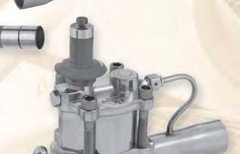
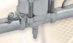

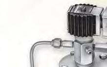


121 Pressure Regulating Valves Precise control of temperatures in evaporators Economical method of compressor capacity control Prevent overloading to the compressor High and low ambient stability Defrost differential control 6
122 Electric Stepper Motor Control Valves for the Suction Line The CDS valves are designed for more precise and energy efficient control of temperatures in evaporators. Proper temperature is obtained by regulating refrigerant flow in the evaporator in response to signals generated by an electronic controller and sensor combination. The valves are built around balanced ports, which allows input power of only 4 watts, less than one quarter of the power used by older heat motor and analog designs. When not actively stepping, power to the motor is removed for further energy savings. The step motors used are standard 12-Volt DC bipolar designs, which in concert with the integral gear reduction, give the valves unsurpassed accuracy and repeatability over the entire operating range. Since the valves are powered from an external controller, no pilot lines or high to low side bleeds are required. The properly applied CDS valve and controller can replace standard mechanical evaporator pressure regulators (EPR), suction stop solenoid valves, and conventional thermostats. With different seating materials, CDS-16 valves may be applied as heat reclaim, head pressure control, or liquid line differential valves. CDS-9 and -17 are suitable for these applications as supplied. Contact Race Division for more information. Due to the stepper motor design, the CDS Series are the first evaporator control valves that may be sized to contribute NO additional pressure drop to the suction line. Simplified cartridge design allows all moving parts to be replaced as a unit. Only the valve body is left in the line. This will allow maintenance or repair without unsweating the entire valve. CDS - Valve Nomenclature/Ordering Instructions The CDS-16 is the only angled valve. The CDS-4, CDS-7, CDS-9 and CDS-17 are straight through valves. CDS - T /8 x 1-3/8 ODF S Controls Discharge Stepmotor Optional Inlet Pressure Tap Model Number Fitting Size Cable Length 20' = 6m 10' = 3m S = Stripped and tinned cable ends. When installing theses valves with solder connections, the internal parts should be protected from overheating by using a Parker calorie discharger (TB2) - see page 271- or by wrapping the valve with a wet cloth. For all requests, consult your nearest Wholesaler or contact us on: 122 RACE Catalogue R & A/C gal-1a/uk - Ed. November 2011
123 Index Pressure Temperature Regulating Valves Electric Pressure Temperature Regulating Valves Stepper Motor Valves for the Suction Line CDS 4, 7, 9, 17, 16 Stepper Motor Discharge Bypass Valves SDR 3, 3X, SDR4 Pressure Regulating Valves Discharge Bypass Valves Crankcase Pressure Regulating Valves Head Pressure Control Valves Defrost Differential Pressure Regulating Valves Evaporator Pressure Regulating Valves reserves the right to change this document without notice. For all requests, consult your nearest Wholesaler or contact us on: 123 RACE Catalogue R & A/C gal-1a/uk - Ed. November 2011
124 Stepper Motor Valves for the Suction Line Valves Specifications Valve CDS(T)-4 and -7 CDS(T)-9,-17 and -16 Motor Type Compatible Refrigerant 2 phase, bipolar wet motor All common CFC, HCFC and HFC refrigerants, including R-410A and subcritical R-744 Compatible Oils All common Mineral, Polyolester and Alkybenzene oils Supply Voltage 12 VDC -5% +10% measured at the valve leads Cable Type IP66 Removable Hermetic Phase Resistance 100 Ohms ± 10% 75 Ohms ± 10% Current Range 104 to 147 ma / winding 131 to 215 ma / winding Power Input 3 W 4 W Recommended Step Rate 200 / s 200 / s Number of Steps Full Motor Transit Time 12.5 seconds 34 seconds Resolution " (.003 mm) / step " (.002 mm) / step. Total Stroke 0.297" (7.54 mm).50" (12.7 mm) MRP 700 psig (48 bar) 680 psig (47 bar) Max Internal Leakage Less than psig (6.9 barg) Max External Leakage psig ( barg) Operating Temp. Range Materials of Construction -50 F to 140 F (-45 C to 60 C) Brass, copper, synthetic seals, stainless steel Available Connections Valve Inlet Outlet Configuration Cable Length Cable Type Inches (ODF) Inches (ODF) Feet Meters Ends CDS(T)-4 1/2, 5/8, 7/8 1/2, 5/8, 7/8 CDS(T)-7 5/8, 7/8, 1-1/8, 1-3/8 5/8, 7/8, 1-1/8, 1-3/8 Straight S Through Stripped CDS(T)-9 5/8, 7/8, 1-1/8, 1-3/8 5/8, 7/8, 1-1/8, 1-3/8 Offset 10, 20 3, 6 and CDS(T) /8, 1-5/8, 2-1/8 1-3/8, 1-5/8, 2-1/8 Tinned CDS(T) /8 1-3/8 Angle For all requests, consult your nearest Wholesaler or contact us on: 124 RACE Catalogue R & A/C gal-1a/uk - Ed. November 2011
125 Stepper Motor Valves for the Suction Line Selection Table Capacities in kw Type CDS-4 Evaporator Temp. C Refrigerant 134a 404A/ C 410A Pressure Drop Across Valve - bar CDS CDS CDS CDS Capacities based on 16 C liquid and 14 C superheated vapor. Liquid Temperature Entering TEV TEV C Refrigerant Correction Factor, CF 134a A/ C A Use the correction factor for 38 C liquid temperature and the capacities at 5 C evaporator temperature to determine ARI standard capacity ratings. Example: The capacity of a CDS-7 using R-407C, evaporator temperature of -20 C, 0.06 bar pressure drop across the valve and a liquid temperature of 10 C is equal to (8.38 x 1.05) 8.79 kilowatts. These factors correct for net refrigerating effect and are based on an average temperature of -15 C. However, they may be used for any evaporator temperature from -30 C to 0 C since the variation in the actual factors across this range is insignifi cant. For all requests, consult your nearest Wholesaler or contact us on: 125 RACE Catalogue R & A/C gal-1a/uk - Ed. November 2011
126 IN Stepper Motor Valves for the Suction Line Valves Dimensions CDS-4.63 MIN. BEND RADIUS CDS-7.63 MIN. BEND RADIUS 112 mm 46 mm.59" IN 1/4 SAE 1.25 (32) HEX 184 mm 110 mm.69" 41 mm 32 mm HEX 1/4 SAE 184 mm 32 mm 38 mm CDS-9 CDS mm 1/4 SAE Optional Pressure Tap 134 mm 1/4 SAE Optional Pressure Tap 143 mm 35 mm HEX 46 mm HEX 18 mm 23 mm 184 mm 184 mm 38 mm 55 mm 48 mm 55 mm CDS mm 54 mm HEX 1/4 SAE Optional Pressure 53 mm Tap 103 mm 104 mm For all requests, consult your nearest Wholesaler or contact us on: 126 RACE Catalogue R & A/C gal-1a/uk - Ed. November 2011
127 Stepper Motor Valves for the Suction Line Order Selection Guide Type Connections Body Configuration Cable length in meter Kv m³/h Part Number 1/2" x 1/2'' ODF CDS-4 5/8" x 5/8 ODF Straight Through Offset /8" x 7/8" ODF /2" x 1/2'' ODF Special order valve CDST-4 5/8" x 5/8 ODF Straight Through Offset With Pressure Tap /8" x 7/8" ODF /8" x 5/8" ODF CDS-7 78" x 7/8" ODF / Special order valve Straight Through Offset 3 1-1/8" x 1-1/8" ODF /8" x 1-3/8" ODF Special order valve /8" x 5/8" ODF CDST-7 78" x 7/8" ODF / Straight Through Offset /8" x 1-1/8" ODF With Pressure Tap /8" x 1-3/8" ODF /8" x 5/8" ODF CDS-9 78" x 7/8" ODF / Straight Through Offset 3 1-1/8" x 1-1/8" ODF /8" x 1-3/8" ODF /8" x 5/8" ODF CDST-9 78" x 7/8" ODF / Straight Through Offset /8" x 1-1/8" ODF With Pressure Tap /8" x 1-3/8" ODF /8" x 1-3/8 ODF CDS /8" x 1-5/8 ODF Straight Through Offset /8" x 2-1/8" ODF /8" x 1-3/8 ODF CDST /8" x 1-5/8 ODF Straight Through Offset With Pressure Tap /8" x 2-1/8" ODF CDS /8" x 1-3/8" ODF Angle CDST /8" x 1-3/8" ODF Angle With Pressure Tap 6 Special order valve 6 For all requests, consult your nearest Wholesaler or contact us on: 127 RACE Catalogue R & A/C gal-1a/uk - Ed. November 2011
128 CDS Valve Kits Motor Kits for CDS(T) Valves Valve Type KIT No. Part Number CDS(T)-4 KS-CDS(T) CDS(T)-7 KS-CDS(T) CDS(T)-9 KS-CDS(T) CDS(T)-17 KS-CDS(T) CDS(T)-16 KS-CDS(T) Cable Assembly Kits for CDS(T) Valves Valve Type Cable Length Part Number 3 m CDS(T)-4, -7 6 m m m Motor Kit CDS-4, -7 Motor Kit CDS-9, -17, -16 Gasket (CDS-4 only) Cable Kit CDS(T)-4, -7 For complete information, consult your nearest Wholesaler. Components & Accessories Product Part Number Description IB2 Interface Board (2500 steps) IB6 Interface Board (6386 steps) For all requests, consult your nearest Wholesaler or contact us on: SMA-12 Stepper Motor Actuator Test Instrument 128 RACE Catalogue R & A/C gal-1a/uk - Ed. November 2011


129 Stepper Motor Discharge Gas Bypass Valves SDR Series valves are Step Discharge Regulators, or electrically operated discharge gas bypass valves. Unlike previous mechanical discharge gas bypass valves that only control a downstream pressure, the SDR Series offers direct temperature control of air or liquid. The valves use the same 12 V DC bipolar step motor as all other step motor operated valves, including the CDS valves above. Balanced pistons and ports, uniquely characterized for hot gas flow, have been incorporated into the design. Seating materials, motors and gears have all been laboratory and field proven in high temperature gas applications. With capacities up to 25 nominal R-22 tons, the SDR Series is suitable for use in small process chillers and environmental chambers, as well as large direct expansion air conditioning applications. The valves may be controlled by third party controllers or by the IB interface board. SDR valves are normally installed in the same manner as mechanical discharge gas bypass valves; in a bypass branch of the discharge gas line. The valves may be piped to feed into the evaporator at the distributor, downstream of the evaporator, or at the compressor suction. Contact "racecustomerservice@parker.com" for additional piping recommendations. When applied with a third party controller or DDC building management system, the SDR can be used with the IB as an interface to the existing system. SDR - Valve Nomenclature/Ordering Instructions 6 S DR - 4-7/8 x 7/ S Step Motor Operated Discharge Regulator Nominal Size 3 or 4 available Connetions ODF SDR-3 3x - 3/8, 1/2, 5/8 SDR-4-7/8 1-1/8 When installing theses valves with solder connections, the internal parts should be protected from overheating by using a Parker calorie discharger (TB2) - see page 271- or by wrapping the valve with a wet cloth. For all requests, consult your nearest Wholesaler or contact us on: Cable Length 10 standard, 20' = 6m 10' = 3m S = Stripped and tinned cable ends. 129 RACE Catalogue R & A/C gal-1a/uk - Ed. November 2011
130 SDR Specifications Valve SDR-3 and 3x SDR-4 Motor Type Compatible Refrigerant Compatible Oils Supply Voltage 2 phase, bipolar wet motor All common CFC, HCFC and HFC refrigerants, including R-410A and subcritical R-744 All common Mineral, Polyolester and Alkybenzene oils 12 VDC -5% +10% measured at the valve leads Cable Type Hermetic Hermetic Phase Resistance 75 Ohms ± 10% 75 Ohms ± 10% Current Range 131 to 215 ma / winding 131 to 215 ma / winding Power Input 4 W 4 W Recommended Step Rate 200 / s 200 / s Number of Steps Full Motor Transit Time 16 seconds 34 seconds Resolution " (.002 mm) / step " (.002 mm) / step. Total Stroke 0.250" (6.4 mm).50" (12.7 mm) MRP 700 psig (48 barg) 700 psig (48 barg) Max Internal Leakage Max External Leakage Operating Temp. Range Fluid Operating Temp. Range Ambient Materials of Construction Less than psig (6.9 barg) psig ( barg) -40 F to 240 F (-40 C to 116 C) -40 F to 140 F (-40 C to 60 C) Brass, copper, synthetic seals, stainless steel Available Connections Valve Inlet Outlet Configuration Cable Length Cable Type Inches (ODF) Inches (ODF) Feet Meters Ends SDR-3 3/8, 1/2, 5/8 3/8, 1/2, 5/8 Angle (S- Stripped and SDR-3x 3/8, 1/2, 5/8 3/8, 1/2, 5/8 10, 20 3, 6 Tinned) SDR-4 7/8, 1-1/8 7/8, 1-1/8 Straight Through Offset For all requests, consult your nearest Wholesaler or contact us on: 130 RACE Catalogue R & A/C gal-1a/uk - Ed. November 2011
131 SDR Selection Tables Capacities in kw Refrigerant a 404/ C 410A Valve Type Minimum Allowable Evaporator Temperature at Reduced Load C Condensing Temperature C SDR SDR-3X SDR SDR SDR-3X SDR SDR SDR-3X SDR SDR SDR-3X SDR SDR SDR-3X SDR Note: Capacities are based on discharge temperature 28 C above isentropic compression, 55 C condensing temperature, 0 C subcooling, 13 C superheat at the compressor and includes both the hot gas bypassed and the liquid refrigerant for desuperheating, regardless of whether the liquid is fed through the system thermostatic expansion valve or auxiliary desuperheating expansion valve. Valve Dimensions SDR-3, 3X 55 mm SDR mm 209 mm 60 mm 66 mm For all requests, consult your nearest Wholesaler or contact us on: 205 mm 131 RACE Catalogue R & A/C gal-1a/uk - Ed. November 2011
132 Order Selection Guide Type SDR-3 SDR-3x SDR-4 Connections Body Configuration Cable length in meter Kv m³/h Part Number 3/8" x 3/8'' ODF /2" x 1/2'' ODF Angle /8" x 5/8 ODF /8" x 3/8'' ODF /2" x 1/2'' ODF Angle /8" x 5/8 ODF " x 7/8" ODF Straight Through /8" x 1-1/8" ODF Offset SDR Valve Kits Motor kits for SDR Valves Valve Type Kit Number Part Number SDR-3 KS-SDR SDR-3x KS-SDR-3x SDR-4 KS-SDR Motor Kit SDR-3, 3X Motor Kit SDR-4 For all requests, consult your nearest Wholesaler or contact us on: 132 RACE Catalogue R & A/C gal-1a/uk - Ed. November 2011


133 Components & Accessories Product Part Number Description IB3 Interface Board (3193 steps) IB6 Interface Board (6386 steps) SMA-12 Stepper Motor Actuator Test Instrument The IB interface board allows all stepper motors to be modulated in response to an externally generated signal. The IB accept a 4-20 ma, or 0-10 Volt DC inputs and stroke the valve proportionately to that signal. The IB allow use of the CDS or SDR valves with an existing DDC system or other generic temperature controller for hot gas bypass, evaporator temperature, or reclaim applications. The IB interface board have screw terminals for easy connections, and should be mounted in a control panel or other enclosure. CN4 CN Black White Green Red IN GND 24V+ 24V- 6 For all requests, consult your nearest Wholesaler or contact us on: CN3 133 RACE Catalogue R & A/C gal-1a/uk - Ed. November 2011


134 Discharge Bypass Valves The line of discharge bypass valves are designed to provide an economical method of compressor capacity control in place of cylinder unloaders or to handle unloading requirements below the last step of cylinder unloading. These modulating control valves automatically bypass the required amount of discharge gas to the low side to maintain the desired minimum evaporator pressure. The valves are applicable on any refrigeration or air conditioning system that operates during periods of low load, which can result in coil icing or short cycling. These valves respond to downstream pressure changes and open when the evaporator pressure falls below the valve setting. At normal loads and evaporator conditions, the valve remains closed and the system operates in a conventional manner. The DR line of valves consists of three basic types of valves: the adjustable models, the adjustable remote bulb models, and the non-adjustable models. The SHGB valves are adjustable and pilot operated with a solenoid stop feature that eliminates the need for a hot gas solenoid valve. They were developed for use on larger capacity systems. Application The discharge bypass valve is normally applied in a branch line off the discharge line. To allow system pump down control, a solenoid valve or hand valve must be installed upstream of the discharge DR type bypass valves. The bypassed hot gas can enter the low side at several locations; however, two of the possible locations are preferred because of superior operating performance: into the side connection of a side connection distributor or directly into the suction line. By using the side connection distributor method, the system TEV will act as a desuperheating valve to keep the compressor suction temperature below the recommended maximum temperature published by the compressor manufacturer. When the hot gas is bypassed directly into the suction line, an auxiliary desuperheating TEV may be required. See Bulletin and for complete application details. Selection and Capacity Ratings The capacities given in the table below are valve hot gas capacities and not the capacities of the system on which the valve is to be applied. To select a valve, fi rst determine the compressor capacity at the minimum allowable evaporating temperature. Then the discharge bypass valve must supply the difference between this compressor capacity and the minimum evaporator load at which the system is to be operated. The valve pressure setting will be that pressure at which the bypass valve must start to open. 134 RACE Catalogue R & A/C gal-1/uk - Ed. November 2011
135 Valve Nomenclature/Ordering Instructions Direct Acting Valves A DR H E 6 0/80 AR 7/8" ODF Fully Adjustable 0/30 or 0/80 psig or 0/55 psig (ADRI) Valve Type Discharge Regulating Body Style I, S, P, or H External Equalizer Omit if Internally Equalized Port Size in Eighths of an Inch Adjustable Range 0/30, 0/80, 55/70, etc Adjustable Remote Bulb Connections Solder or SAE Flare When installing theses valves with solder connections, the internal parts should be protected from overheating by using a Parker calorie discharger (TB2) - see page 271- or by wrapping the valve with a wet cloth. Specifications & Materials/Details of Construction Valve Type ADRI, ADRS, ADRP, DRHE, ADRHE Body Material Brass Seat Metal to Metal Synthetic to Metal Element to Body Joint Type Knife Edge Metal to Metal Connections ODF Copper, SAE Brass Element Type Stainless Steel Diaphragm MRP 34.5 barg (500 psig) Max External Leakage psig ( barg) UL SA5460 Compatibility All HFC, HCFC, Refrigerants and blends Pilot Operated Valves S HGB E - 8-0/100-7/8" Solenoid Stop Feature Valve Type Hot Gas Bypass External Equalize 1/4" SAE Omit if Internally Equalized Specifications & Materials/Details of Construction Valve Size For all requests, consult your nearest Wholesaler or contact us on: Adjustment Range psi Valve Type SHGB-8, SHGBE-8 SHGB-15, SHGB-15 Body Material Brass Cast Steel Seat Synthetic to Metal Connections ODF Copper Coil MKC-1 MKC-2 MRP 33 barg (450 psig) MOPD 20.7 bar (300 psi) Max. Fluid Temp. 116 C (240 F) Max. Ambient Temp C (120 F) Max External Leakage psig ( barg) UL MH4576 Compatibility All HFC, HCFC, Refrigerants and blends Connections ODF Solder 7/8" ODF 1-1/8" ODF RACE Catalogue R & A/C gal-1a/uk - Ed. November 2011
136 Selection Tables Capacities in kw Capacities based on 3.3 C evaporator temperature change from closed to rated opening (does not apply to pilot operated models), discharge temperature 17 C above isentropic compression, 38 C condensing temperature, 0 C subcooling, 14 K superheat at the compressor and includes both the hot gas bypassed and liquid refrigerant for desuperheating, regardless of whether the liquid is fed through the system thermostatic expansion valve or auxiliary desuperheating thermostatic expansion valve. Refrigerant a 404A 407C 507 Minimum Allowable Evaporator Temp. C ADRI-1-1/4 ADRIE-1-1/4 Valve Type & Adjustment Range (bar) ADRS-2 ADRP-3 ADRHE-6 DRHE-6 (Adjustable "Remote Bulb" Model)* SHGB-8 SGHBE-8 SHGB-15 SGHBE-15 0/3.79 0/5.17 0/6.90 0/2.07 0/5.52 0/2.07 0/5.52 0/2.07 0/ / / / /5.52 0/6.90 0/ * These models applicable on air conditioning systems only. R410A Direct Acting Specifi cations & Materials / Details of Construction Pilot Operated Valves Specifi cations & Materials/Details of Construction Valve Type HGBE Valve Type HGB(E) Body Material Seat Connections MRP Max. Fluid Temp. Max. Ambient Temp. Max External Leakage UL Compatibility Brass Synthetic to Metal ODF Copper 48.3 barg (700 psig) 116 C (240 F) 48.9 C (120 F) psig ( barg) SA-5460-SFJQ2 All HFC Refrigerants and blends Body Material Seat Connections MRP Max. Fluid Temp. Max. Ambient Temp. Max External Leakage UL Compatibility For all requests, consult your nearest Wholesaler or contact us on: Brass Synthetic to Metal ODF Copper 48.3 barg (700 psig) 116 C (240 F) 48.9 C (120 F) psig ( barg) SA-5460-SFJQ2 All HFC Refrigerants and blends 136 RACE Catalogue R & A/C gal-1a/uk - Ed. November 2011
137 Selection Tables R410A Capacity Multipliers kw / bar / C For evaporator temperature changes other than 3.3 C nominal change. Evaporator Temperature Change C Evaporator Temperature C Direct Acting Discharge Bypass Valve Capacities - kw / bar / C Valve Type Adjustment Range (bar) Minimum Allowable Evaporator Temperature at Reduced Load C Condensing Temperature C HGBE-5 6.6/ Pilot Operated Discharge Bypass Valve Capacities Valve Type HGB-8 HGBE-8 Adjustment Range (bar) Minimum Allowable Evaporator Temperature at Reduced Load C Condensing Temperature C / Capacities based on discharge temperatures 28 C above isentropic compression, 14 C superheat at the compressor, 5 C subcooling, and includes both the hot gas bypassed and liquid refrigerant for desuperheating, regardless of whether the liquid is fed through the system thermostatic expansion valves or an auxiliary desuperheating thermostatic expansion valve. 6 For example, an HGBE-5 rated for 20.1 kw at a -3 C evaporating temperature will start to open at 0.3 C (-3 C C); and when the evaporating temperature has dropped to -3 C, the valve will be open far enough to bypass 20.1 kw of hot gas. For all requests, consult your nearest Wholesaler or contact us on: 137 RACE Catalogue R & A/C gal-1a/uk - Ed. November 2011
138 Valve Dimensions HGBE mm Top View mm mm IN D C mm 1/4 ODF 1.84 External 46.7 mm 3.12 Equalizer 79.2 mm Connection A B Connections ODF Solder Inches mm Inches A B C D A B C D 3/ / / HGBE-8 Externally Equalized HGBE-8 Internally Equalized mm mm mm mm mm mm mm mm mm mm mm mm For all requests, consult your nearest Wholesaler or contact us on: 138 RACE Catalogue R & A/C gal-1a/uk - Ed. November 2011
139 Order Selection Guide Direct Acting Valves - Adjustable Models Type Connections Inches Adjustment Range (psig) Adjustment Range (barg) Part Number 3/8 ODF 0/55 0/ /8 ODF 0/75 0/ /8 ODF 0/100 0/ /8 ODF 0/55 0/ /8 ODF 0/75 0/ /8 ODF 0/100 0/ ADRS-2 3/8 ODF, 1/2 ODF, 5/8 ODF 0/30, 0/80 0/2.07, 0/5.52 Special order valve 3/8 ODF, 1/2 ODF, 5/8 ODF 0/30 0/2.07 Special order valve ADRSE-2 3/8 ODF /2 ODF 0/80 0/ /8 ODF ADRP-3 1/2 ODF, 0/30, 0/80 0/2.07, 0/5.52 5/8 ODF Special order valve 1/2 ODF, 5/8 ODF 0/30 0/2.07 ADRPE-3 1/2 ODF /80 0/5.52 5/8 ODF /8 ODF /8 ODF 0/30 0/ ADRHE-6 1-1/8 ODF /8 ODF /8 ODF 0/80 0/ /8 ODF ADRI-1-1/4 (straight through) ADRIE-1-1/4 (straight through) Direct Acting Valves - With Adjustable Remote Bulb DRP-3-AR /8 ODF 55/ /4.83 DRPE-3-AR /8 ODF / / /8 ODF /8 ODF DRHE-6-AR 55/ / /8 ODF /8 ODF / / /8 ODF For all requests, consult your nearest Wholesaler or contact us on: 139 RACE Catalogue R & A/C gal-1a/uk - Ed. November 2011
140 Order Selection Guide Pilot Operated * Type Connections Inches Adjustment Range (psig) Adjustment Range (barg) Coil Type Required Part Number HGBE-8 7/8 ODF 75/ /8 ODF SHGB-8 1-1/8 ODF /100 0/6.9 MKC-1 7/8 ODF SHGBE-8 1-1/8 ODF /8 ODF SHGB /8 ODF /75 0/5.17 MKC-2 1-1/8 ODF SHGBE /8 ODF Adjustable Spring R-410A Models 3/8 ODF HGBE-5 1/2 ODF 95/ / /8 ODF HGB-5 3/8 ODF, 1/2 ODF, 5/8 ODF 95/ / Special order valve Pilot Operated R-410A Models HGBE-8 HGB-8 7/8 ODF Special order valve 75/ / /8 ODF /8 ODF 75/ / Special order valve 1-1/8 ODF *All PRV's are supplied less coil. Din Coils Part Number Type Power Electrical Connections MKC-1E 24/ W DIN connector (not included) MKC-1E 120/ W DIN connector (not included) MKC-1E /50 10 W DIN connector (not included) MKC-1E / W DIN connector (not included) MKC-2E 24V 50-60HZ 15W DIN connector (not included) MKC-2E 120/ W DIN connector (not included) MKC-2E /50 15W DIN connector (not included) MKC-2E / W DIN connector (not included) MKC-1E 12 DC 15W DIN connector (not included) MKC-1E 24 DC 15W DIN connector (not included) MKC-2E 24 DC 18W DIN connector (not included) R PG 9/11 DIN connector for MKC-1E and MKC-2E coils For all requests, consult your nearest Wholesaler or contact us on: 140 RACE Catalogue R & A/C gal-1a/uk - Ed. November 2011


141 Crankcase Pressure Regulating Valves Crankcase Pressure Regulating Valves are designed to prevent overloading of the compressor motor by limiting the crankcase pressure to a predetermined maximum value during and after a defrost cycle or a normal shutdown period. These valves automatically throttle the vapour flow from the evaporator until the compressor can handle the load. manufactures five adjustable direct acting models...cro-4, CRO-6, CROT-6, CRO-10 and CROT all models respond only to their outlet pressure and modulate to prevent the suction pressure at the compressor from rising above the valve setting. Since these valves are adjustable, the setting may be altered to suit the specific system requirements. Selection and Capacity Ratings The ratings for these valves vary depending on these items: design suction pressure after pulldown, maximum allowable suction pressure recommended by the compressor or unit manufacturer (this is the valve setting), and pressure drop across the valve. The difference between the design suction pressure and the valve setting determines how much of the valve stroke is used. Therefore, the valve setting should be kept as high as possible without exceeding the recommendation of the compressor or unit manufacturer. Once this information is available, the correct CRO can be selected from the data below. 6 Installation Crankcase pressure regulating valves are installed in the suction line between the evaporator and compressor, and downstream of any other controls or accessories. When installing CRO s with solder type connections, the internal parts should be protected by wrapping the valve with a wet cloth. For all requests, consult your nearest Wholesaler or contact us on: 141 RACE Catalogue R & A/C gal-1a/uk - Ed. November 2011
142 Valve Nomenclature/Ordering Instructions CRO T 10 0/60 1-1/8 ODF Valve Type Close on rise of outlet pressure Access Valve on Inlet Connection CROT-6 or CROT-10 Port Size in Eighths of an Inch Adjustment Range - psig See specifi cations for available adjustement ranges Connection ODF Solder or SAE Flare When installing theses valves with solder connections, the internal parts should be protected from overheating by using a Parker calorie discharger (TB2) - see page 271- or by wrapping the valve with a wet cloth. Materials and Construction Details Valve Type CRO-4 CRO(T)-6 CRO(T)-10 Body Material Brass Brass Seat Tefl on to Metal Tefl on to Metal Element Type and Material Diaphragm - Stainless Steel Bellows - Brass Type of Joints Knife Edge, Metal to Metal Hermetic Construction Connections ODF Copper ODF Copper, SAE Brass ODF Copper MRP 34.5 barg (500 psig) 27.6 barg (400 psig) Max External Leakage psig ( barg) UL SA-5460 Compatibility All HFC, HCFC, Refrigerants and blends For all requests, consult your nearest Wholesaler or contact us on: 142 RACE Catalogue R & A/C gal-1a/uk - Ed. November 2011
143 Selection Tables Capacities in kw Capacities based on 38 C condensing temperature, 6 K superheat, 0 C subcooling and 0.14 bar pressure drop across valve. Type and Adjustment Range CRO-4 0/20 psig 0/1.4 barg CRO-4 0/50 psig 0/3.4 barg CRO-4 0/75 psig 0/5.2 barg CRO(T)-6 0/60 psig 0/4.1 barg CRO(T)-10 0/60 psig 0/4.1 barg CRO(T)-6 30/110 psig 2.1/7.6 barg CRO(T)-10 30/110 psig 2.1/7.6 barg Design Evap. Temp. C Saturated Suction Pressure bar (Reference) R-404A Design Evap. Temp. C Saturated Suction Pressure bar (Reference) R-407C Valve Setting - barg Valve Setting - barg Valve Setting - barg Valve Setting - barg For all requests, consult your nearest Wholesaler or contact us on: 143 RACE Catalogue R & A/C gal-1a/uk - Ed. November 2011
144 Selection Tables Capacities in kw Capacities based on 38 C condensing temperature, 6 K superheat, 0 C subcooling and 0.14 bar pressure drop across valve. Type and Adjustment Range CRO-4 0/20 psig 0/1.4 barg CRO-4 0/50 psig 0/3.4 barg CRO-4 0/75 psig 0/5.2 barg CRO(T)-6 0/60 psig 0/4.1 barg CRO(T)-10 0/60 psig 0/4.1 barg CRO(T)-6 30/110 psig 2.1/7.6 barg CRO(T)-10 30/110 psig 2.1/7.6 barg Design Evap. Temp. C Saturated Suction Pressure bar (Reference) R-22 Design Evap. Temp. C Saturated Suction Pressure bar (Reference) R-134a Valve Setting - barg Valve Setting - barg Valve Setting - barg Valve Setting - barg For all requests, consult your nearest Wholesaler or contact us on: 144 RACE Catalogue R & A/C gal-1a/uk - Ed. November 2011
145 Selection Tables Capacities in kw Capacities based on 38 C condensing temperature, 6 K superheat, 0 C subcooling and 0.14 bar pressure drop across valve. Type and Adjustment Range CRO-4 0/20 psig 0/1.4 barg CRO-4 0/50 psig 0/3.4 barg CRO-4 0/75 psig 0/5.2 barg CRO(T)-6 0/60 psig 0/4.1 barg CRO(T)-10 0/60 psig 0/4.1 barg CRO(T)-6 30/110 psig 2.1/7.6 barg CRO(T)-10 30/110 psig 2.1/7.6 barg Design Evap. Temp. C Saturated Suction Pressure bar (Reference) R-409A Design Evap. Temp. C Saturated Suction Pressure bar (Reference) R-507 Valve Setting - barg Valve Setting - barg Valve Setting - barg Valve Setting - barg For all requests, consult your nearest Wholesaler or contact us on: 145 RACE Catalogue R & A/C gal-1a/uk - Ed. November 2011
146 Valve Dimensions CRO (T)-6 CRO (T)-10 CRO 4 A 117 C D B A B Specifications & Dimensions Valve type CRO-4 CRO(T)-6 CRO(T)-10 Nominal Adjustment Range - psig 0/20, 0/50 or 0/75 0/60 or 30/110 0/60 or 30/110 Connection - Inches Standard Connection in Bold Dimensions - Inches A B C D Socket Depth Weight - Pounds Net Shipping 3/8 ODF Solder /2 ODF Solder /8 SAE Flare /2 SAE Flare /8 ODF Solder /8 ODF Solder /8 ODF Solder /2 SAE Flare /8 SAE Flare /8 ODF Solder /8 ODF Solder /8 ODF Solder For all requests, consult your nearest Wholesaler or contact us on: 146 RACE Catalogue R & A/C gal-1a/uk - Ed. November 2011
147 Order Selection Guide Crankcase Pressure Regulating Valves Type CRO-4 CRO-6 CRO-10 CROT-6 CROT-10 Connections Inches Adjustment Range (psig) Adjustment Range (barg) Part Number 1/2 ODF 0/20 0/ /2 ODF 0/50 0/ /2 ODF 0/75 0/ /8 ODF, 3/8 SAE, 1/2 SAE 0/20, 0/50, 0/75 0/1.38, 0/3.45, 0/5.17 Special order valve 5/8 ODF / /7.58 7/8 ODF /8 ODF /2 SAE 0/60 0/ /8 SAE /2 SAE, 5/8 SAE, 1/2 ODF, 5/8 ODF, 7/8 ODF, 1-1/8 ODF 0/60, 30/110 0/4.14, 2.07/7.58 Special order valve 7/8 ODF /8 ODF 30/ / /8 ODF /8 ODF /8 ODF 0/60 0/ /8 ODF /2 SAE /8 SAE /2 ODF /60 0/4.14 5/8 ODF /8 ODF /8 ODF /2 SAE /8 SAE /2 ODF / /7.58 5/8 ODF /8 ODF /8 ODF /8 ODF /8 ODF 0/60 0/ /8 ODF /8 ODF /8 ODF 30/ / /8 ODF Note: All CRO & CROT valves with ODF connections are supplied with an inlet strainer 6 Special order valves or other valves confi gurations might be available upon request. For all requests, consult your nearest Wholesaler or contact us on: 147 RACE Catalogue R & A/C gal-1a/uk - Ed. November 2011


148 Head Pressure Control Valves High and Low Ambient Stability The design of air conditioning systems utilizing air cooled condensing units involves two main problems that must be solved if the system is to operate reliably and economically high ambient and low ambient operation. If the condensing unit is properly sized, it will operate satisfactorily during extremely high ambient temperatures. However, some units will be required to operate at ambient temperatures below their design dry bulb temperature during most of the year, the solution to low ambient operation is more complex. Without good head pressure control during low ambient operation, the system can experience both running cycle and off-cycle problems. Since the pressure differential across the thermostatic expansion valve port affects the rate of refrigerant flow, low head pressure generally causes insufficient refrigerant to be fed to the evaporator. Failure to have sufficient head pressure will result in low suction pressure and/or iced evaporator coils. The primary off-cycle problem is refrigerant migration to the condenser. Insufficient flow through the TEV will cause a low suction pressure. The typical method of maintaining normal head pressure in a refrigeration system during periods of low ambient temperature is to restrict liquid flow from the condenser to the receiver, and at the same time divert hot gas to the inlet of the receiver. This backs liquid refrigerant up into the condenser reducing its capacity which in turn increases the condensing pressure. At the same time the hot gas raises liquid pressure in the receiver, allowing the system to operate normally. Head Pressure Control for systems with air cooled condensers can be accomplished using one of several valve options; the non-adjustable OROA-5, the adjustable ORI/ORD combination, or the economical LAC Series. For all requests, consult your nearest Wholesaler or contact us on: 148 RACE Catalogue R & A/C gal-1a/uk - Ed. November 2011
149 Valve Nomenclature/Ordering Instructions LAC LAC DS - 100/80-3/8 " X 3/8 " X 3/8 " Valve Type Low Ambient Control Valve Size Dual Setting Omit for standard dome element Valve Setting (s) (psig) - Specify one setting for Discharge Connection (inches) Condensed Connection (inches) Receiver Connection (inches) LAC /8" X 5/8" X 3/8 " ODF Valve Type Low Ambient Control Valve Size Valve Setting(s) (psig) Discharge Connection (inches) Condensed Connection (inches) Receiver Connection (inches) Solder Connections ORI ORI /225-7/8" ODF - With Strainer - H Valve Type Open on rise of Inlet Pressure Port Size Eighths of an Inch Nominal Adjustment Range (psig) Connection Solder Inlet Strainer (Optional) Designates High Pressure Bellows OROA OROA /8" ODF - With Strainer Valve Type Open on rise of Outlet Port Size Eighths of an Inch Pressure Setting (psig) Connection Solder Inlet Strainer (Optional) ORD-4 ORD Valve Type Open on rise of Differential Pressure Port Size Eighths of an Inch Opening Pressure Differential (psi) Materials and Construction Details Valve Type LAC-4,-5,-10 ORI-6,-10 ORD-4 OROA Body Material Brass Brass Copper Brass Seat Metal to Metal Metal to Metal Metal to Metal Metal to Metal Element Type and Material Type of Joints Domed Steel Remote Bulb only for R410A LAC-5-HP, -10-HP valves Knife Edge, Metal to Metal Bellows - Brass Hermetic Construction Bellows - Brass Hermetic Construction Diaphragm Stainless Stee Hermetic Construction Connections ODF Copper ODF Copper ODF Copper ODF Copper 46.9 barg (680 psig) R410A only MRP LAC-4 =34.5 barg (500 psig) LAC-5, -10 = 31 barg (450 psig) 31 barg (450 psig) 31 barg (450 psig) 31 barg (450 psig) Max External Leakage psig ( barg) UL SA-5460 Compatibility All HFC, HCFC, Refrigerants and blends When installing theses valves with solder connections, the internal parts should be protected from overheating by using a Parker calorie discharger (TB2) - see page 271- or by wrapping the valve with a wet cloth RACE Catalogue R & A/C gal-1/uk - Ed. November 2011
150 Selection Tables Low Ambient Capacities - kw of Refrigeration Capacities are based on -20 C evaporator temperature, 35 C condenser, 6 C subcooled liquid. Refrigerant Valve Setting (barg) C (12.4 barg) 134a (6.9 barg) R-410A (20.3 barg) Minimum Ambient Design Temp. C For all requests, consult your nearest Wholesaler or contact us on: Pressure Valve Type Drop Accross Valve (bar) LAC-4 LAC-5 LAC-10 OROA-5 ORD RACE Catalogue R & A/C gal-1a/uk - Ed. November 2011
151 Selection Tables Low Ambient WINTER Capacities - kw of Refrigeration Capacities are based on -20 C evaporator temperature, 35 C condenser, 6 C subcooled liquid. Refrigerant Valve Setting (barg) Minimum Ambient Design Temp. C Pressure Drop Accross Valve (bar) Valve Type LAC-4 LAC-5 LAC-10 OROA-5 ORD A (14.5 barg) 507 (14.5 barg) For all requests, consult your nearest Wholesaler or contact us on: 151 RACE Catalogue R & A/C gal-1a/uk - Ed. November 2011
152 Selection Tables High Ambient SUMMER Capacities - kw of Refrigeration Capacities are based on -20 C evaporator temperature, 43 C condenser, 6 C subcooled liquid. Refrigerant Valve Setting (barg) C (12.4 barg) 134a (6.9 barg) 410A (20.3 barg) Pressure Valve Type Drop Accross Valve (bar) LAC-4 LAC-5 LAC-10 OROA-5 ORI-6 ORI-10 ORD High Ambient SUMMER Capacities - kw of Refrigeration Capacities are based on -20 C evaporator temperature, 43 C condenser, 6 C subcooled liquid. Refrigerant Valve Setting (barg) 404A (14.5 barg) 507 (14.5 barg) Pressure Valve Type Drop Accross Valve (bar) LAC-4 LAC-5 LAC-10 OROA-5 ORI-6 ORI-10 ORD '7.2 3' '5.4 6' ' For all requests, consult your nearest Wholesaler or contact us on: 152 RACE Catalogue R & A/C gal-1a/uk - Ed. November 2011
153 Valve Dimensions Specifications and Dimensions Valve Type (1) Discharge Connection (2) Condenser Connection Standard Factory Setting bar Connections ODF Solder (Inches) Dimensions - mm Weight kg Replacement Parts Inlet(s) Outlet A B C D E F G I Net Ship 5/8 5/ ORI-6-65/225-H 8.3 7/8 7/ /8 1-1/ /8 1-1/ ORI-10-65/225-H /8 1-3/ ORD /8 5/ OROA-5 6.9, 12.4 or 14.5 (1) 5/8 (2) 5/8 (1) 5/8 (2) 7/8 5/ / Inlet Strainer ORI OROA ORD-4 92 mm A A Receiver Discharge Receiver C B B C Condenser A D Condenser B 6 For all requests, consult your nearest Wholesaler or contact us on: 153 RACE Catalogue R & A/C gal-1a/uk - Ed. November 2011
154 Valve Dimensions Specifications and Dimensions Valve Type LAC-4 LAC-4-DS LAC-5 LAC-10 Standard Factory Setting bar 6.9, 12.4 or 14.5 Connections ODF Solder (Inches) Dimensions - mm Weight kg Inlet(s) Outlet A B C D E F G I Net Ship 1/4 1/ /8 3/ /2 1/ /8 3/ /2 1/ /2 1/ /8 5/ /8 7/ /8 1-1/ (1) 1-3/8 (2) 7/8 (1) 1-3/8 (2) 1-1/8 Dome Element Bulb Element 7/ / (1) Discharge Connection (2) Condenser Connection LAC-4 LAC-4-DS LAC-5 & mm 92 mm 49.3 mm 92 mm R3L Discharge E C A Receiver Condenser B D C Discharge A Receiver Condenser B D E Discharge E C A D3L Receiver Condenser B D 102 mm 19 mm For all requests, consult your nearest Wholesaler or contact us on: 154 RACE Catalogue R & A/C gal-1a/uk - Ed. November 2011
155 Order Selection Guide Head Pressure Control Valves Valve Type Connections - Inches Discharge Condenser/Receiver Standard Factory Setting (psig) Standard Factory Setting (barg) Part Number LAC-4 3/8 ODF 3/8 ODF /2 ODF 1/2 ODF /8 ODF 3/8 ODF /2 ODF 1/2 ODF LAC-4-DS 3/8 ODF 3/8 ODF / /12.4 1/2 ODF 1/2 ODF LAC-4-HP 1/2 ODF 1/2 ODF /8 ODF 5/8 ODF /8 ODF 7/8 ODF /2 x 1/2 ODF, LAC-5 5/8 x 5/8 ODF, 100, /12.4 Special order valve 7/8 x 7/8 ODF, 1-1/8 x 1-1/8 ODF LAC-5-HP 5/8 ODF 5/8 ODF LAC-10 7/8 x 7/8 ODF, 1-3/8 x 1-3/8 ODF 100, /12.4 Special order valve LAC-10-HP 1-3/8 ODF 7/8 ODF /8 ODF 1-1/8 ODF /8 ODF 5/8 ODF ORI-6-65/225H 7/8 ODF 7/8 ODF /8 ODF 1-1/8 ODF ORI-10-65/225H 1-1/8 ODF 1-1/8 ODF /8 ODF 1-3/8 ODF ORD-4 5/8 ODF 5/8 ODF OROA-5 5/8 ODF 5/8 ODF /8 ODF 7/8 ODF /8 ODF 5/8 ODF /8 ODF 7/8 ODF OROAB-5 5/8 ODF 5/8 ODF /8 ODF 7/8 ODF /8 ODF 5/8 ODF /8 ODF 7/8 ODF OROAC-5 OROAD-5 5/8 x 5/8 ODF, 5/8 x 7/8 ODF Special order valve 6 Maximum Pressure Drop Between Compressor and Receiver - bar Below Head Pressure Component Selection OROA or -180 ORD-4-20 & ORI OROAB or -180 ORD-4-25 & ORI OROAC or -180 ORD-4-30 & ORI OROAD or -180 ORD-4-35 & ORI 155 RACE Catalogue R & A/C gal-1/uk - Ed. November 2011
 to the suction line and back through the evaporator being defrosted.")

LDR is designed to maintain a differential pressure between the receiver and the liquid header.")

 pressure and the receiver pressure.")
LDR valves is located between the receiver and the liquid header.")
156 Defrost Differential Pressure Regulating Valves In many supermarket applications refrigerant gas from the discharge line or from the top of the receiver is used for defrost. This method of defrost diverts a portion of the hot gas or cool gas (from the top of the receiver) to the suction line and back through the evaporator being defrosted. DDR-20 OLDR-16 The gas condenses in the evaporator and flows in reverse, through check valves, around the TEV and liquid line solenoid valve. Liquid refrigerant then flows to the liquid header where it is distributed to evaporators not in the defrost cycle. In order for this reverse flow to occur, the pressure of the defrost header must be greater than the pressure of the liquid header. The difference in pressure is known as the defrost differential. Several methods are used to obtain the defrost differential. The (O)LDR is designed to maintain a differential pressure between the receiver and the liquid header. liquid line differential valves have a solenoid bypass feature that allows the valve to remain full open or modulate to maintain a differential. We supply two versions of liquid line differential valves: The OLDR is in the full open position when the coil is de-energized, and it s in differential operation mode when the coil is energized. The LDR is in differential operation mode when the coil is de-energized, and it is in the full open position when the coil is energized. The DDR-20 is designed to create a differential pressure between its inlet (discharge) pressure and the receiver pressure. A solenoid bypass feature is incorporated in the valve so that the valve can be made to go full open when there is no need for a differential to be created. Energizing the solenoid coil opens the valve fully. Location and Piping The (O)LDR valves is located between the receiver and the liquid header. The DDR-20 is located in the discharge line before the condenser. The two types of defrost differential valves (liquid line and discharge line) are not to be applied on the same system. Adjustment Range and Pressure Settings All defrost differential valves are set by turning the adjusting stem located under the cap on the pilot differential valve. The adjustment range is 0.3 to 3.5 bar. The (O)LDR has a factory setting of 1.2 bar and the DDR-20 has a factory setting of 2 bar. Turning the stem clockwise increases the setting, counter clockwise decreases the setting. For all requests, consult your nearest Wholesaler or contact us on: 156 RACE Catalogue R & A/C gal-1a/uk - Ed. November 2011
157 Valve Nomenclature/Ordering Instructions OLDR O - LDR /8" ODF - 120/50-60 Normally Open Liquid Differential Regulator Valve Size Adjustment Range psi Connection (Inches) Electrical Specifications DDR DDR /50-1-5/8" ODF - 120/50-60 Discharge Differential Regulator Valve Size Adjustment Range psi Connection (Inches) Electrical Specifications When installing theses valves with solder connections, the internal parts should be protected from overheating by using a Parker calorie discharger (TB2) - see page 271- or by wrapping the valve with a wet cloth. Specifications Valve Type Port Size mm Differential Setpoint Range Connections - Inches Inlet x Outlet OLDR /8 ODF x 1-1/8 ODF MKC LDR-16 or 1-3/8 ODF x 1-3/8 ODF OMKC-1 OLDR /3.4 bar 1-5/8 ODF x 1-5/8 ODF MKC LDR-20 or 2-1/8 ODF x 2-1/8 ODF OMKC-2 DDR /8 ODF x 1-5/8 ODF MKC-2 Coil MRP MOPD 27.5 bar 20.5 bar Selection Tables Capacities in kw Capacities based on 5 C evaporator temperature, 38 C condensing temperature, 14 K superheat return gas, discharge gas temperature 28 C above isentropic compression. 6 Valve Type Refrigerant 134a 404A & C Pressure Drop Across Valve - bar LDR-16, OLDR LDR-20, OLDR DDR For all requests, consult your nearest Wholesaler or contact us on: 157 RACE Catalogue R & A/C gal-1a/uk - Ed. November 2011
158 Order Selection Guide Valve Type* * All PRV's are supplied less coil. Connection - Inches Inlet x Outlet Coil Type Required Part Number OLDR-16-5/50 1-1/8 ODF x 1-1/8 ODF MKC-1 1-3/8 ODF x 1-3/8 ODF OLDR /8 ODF x 1-5/8 ODF MKC-2 2-1/8 ODF x 2-1/8 ODF DDR-20-5/50 1-5/8 ODF x 1-5/8 ODF MKC LDR-16-5/50 1-3/8 ODF x 1-3/8 ODF OMKC LDR-20-5/50 1-5/8 ODF x 1-5/8 ODF OMKC-2 2-1/8 ODF x 2-1/8 ODF DIN Coils Part Number Type Power Electrical Connections MKC-1E 24 V / Hz 10 W DIN connector (not included) MKC-1E 120 V / Hz 10 W DIN connector (not included) MKC-1E V / 50 Hz 10 W DIN connector (not included) MKC-1E V / Hz 10 W DIN connector (not included) MKC-1E 12 V DC 15 W DIN connector (not included) MKC-1E 24 V DC 15 W DIN connector (not included) MKC-2E 24 V / Hz 15 W DIN connector (not included) MKC-2E 120 V / Hz 15 W DIN connector (not included) MKC-2E V / 50 Hz 15 W DIN connector (not included) MKC-2E V / Hz 15 W DIN connector (not included) OMKC-1E V / 50 Hz 10 W DIN connector (not included) OMKC-2E 120 V / Hz 15 W DIN connector (not included) OMKC-2E V / 50 Hz 15 W DIN connector (not included) OMKC-2E V / Hz 15 W DIN connector (not included) R PG 9/11 DIN connector for MKC-1E and MKC-2E coils For all requests, consult your nearest Wholesaler or contact us on: 158 RACE Catalogue R & A/C gal-1a/uk - Ed. November 2011


159 Evaporator Pressure Regulating Valves The line of evaporator pressure regulating (EPR) valves are designed to provide an accurate and economical means of balancing system capacity and load requirements during "low" loads and/or while maintaining different evaporator conditions on multitemperature evaporator systems. These valves control evaporator temperature by maintaining evaporator pressure. As the evaporator load increases the ORI valves will Open on Rise of Inlet pressure above the valve s setting to provide more flow capacity to meet the evaporator load. When the evaporator load decreases the valves will modulate closed to maintain the pressure setting of the valve. offers a number of Evaporator Pressure Regulating Valves valve types in various sizes,and with optional features to accommodate almost any application requirements. For more complete information on any of the Evaporator Pressure Regulating Valves valve types see your nearest Wholesaler. Application Maintain minimum evaporator temperature to avoid frost on air coils and provide improved humidity control Evaporator temperature control for food merchandisers (single and multiple evaporator systems) Evaporator temperature control on water chilling units 6 Required Sizing Information Refrigerant type Evaporator design capacity Design evaporator temperature or minimum evaporator pressure Available pressure drop Allowable evaporator pressure change (only applies to direct acting models) For all requests, consult your nearest Wholesaler or contact us on: 159 RACE Catalogue R & A/C gal-1a/uk - Ed. November 2011

 Adjustable Hermetic construction (no gaskets or seals) Corrosion resistant construction Inlet pressure tap (standard) Inlet strainer (standard on ODF models)")

160 ORIT-6 & -10 Type These direct acting valves are offered in two sizes. The direct acting design although economical requires an evaporator pressure change above the minimum evaporator pressure setting to provide the rated fl ow capacity. The nominal ratings are based on an 0.55 bar evaporator pressure change for the 0/3.45 barg adjustment range, and a 0.83 bar change for the 2.07/6.90 barg adjustment range. Benefits Direct acting (most economical) Adjustable Hermetic construction (no gaskets or seals) Corrosion resistant construction Inlet pressure tap (standard) Inlet strainer (standard on ODF models) Valve Nomenclature/Ordering Instructions ORIT ORI - T - 6-0/50-7*8" ODF Valve Type Open on Rise of Inlet Pressure Pressure Tap on Inlet Connection Port Size in Eights of an Inch Adjustment Range psig* Connection ODF Solder or SAE Flare * Other pressure ranges are available Installation When installing theses valves with solder connections, the internal parts should be protected from overheating by using a Parker calorie discharger (TB2) - see page 271- or by wrapping the valve with a wet cloth. Specifications & Materials/Details of Construction Valve Type ORIT-6, -10 Body Material Bellows - Brass Seat Metal to Metal Connections ODF Copper or SAE Brass MRP 27.6 barg (400 psig) Max. Fluid Temp. 116 C (240 F) Max. Ambient Temp C (155 F) Max External Leakage psig ( barg) UL SA-5460-SFJQ Compatibility All HFC, HCFC Refrigerants and blends Valve Type *Not available with inlet strainer. Port Size mm Adjustment Range Standard Connections In Bold 1/2 & 5/8 SAE Flare* ORIT /3.45 1/2, 5/8, 7/8 & 1-1/8 ODF Solder 2.07/6.90 bar ORIT /8, 1-1/8 & 1-3/8 ODF Solder 160 RACE Catalogue R & A/C gal-1/uk - Ed. November 2011
161 Selection Tables Valves should be selected for the desired maximum variation in evaporator pressure using the capacity multipliers below. Allowable Evaporator Pressure Change - bar Capacity ORIT-6, 10-0/ Multiplier ORIT-6, 10-30/ Capacities in kw Capacities based on 38 C condensing temperature, 0 C subcooling, 6 K superheat, 0.55 bar evaporator pressure change for 0/3.45 barg adjustment range, and a 0.83 bar evaporator pressure change for 2.07/6.90 barg adjustment range. Valve Type Evaporator Temperature C Saturated Pressure - bar (Reference) Refrigerant a 404A 407C 507 Pressure Drop Across Valve - bar Refrigerant a 404A 407C ORIT ORIT Order Selection Guide Direct Acting Type - With inlet strainer (40 MESH) where applicapable Type Connections Inches Adjustment Range (psig) Adjustment Range (barg) Part Number 1/2 ODF /8 ODF 0/50 0/ /8 ODF /2 ODF /8 ODF 30/ / ORIT-6 7/8 ODF /2 SAE /50 0/3.45 5/8 SAE /2 SAE / /6.9 5/8 SAE /8 ODF 0/50, 30/100 0/3.45, 2.07/6.9 Special order valve 7/8 ODF /8 ODF 0/50 0/ ORIT /8 ODF /8 ODF /8 ODF 30/ / /8 ODF RACE Catalogue R & A/C gal-1/uk - Ed. November 2011


ORIT S ORI T - 15-0/100-1-3/8 \" ODF - 120/50-60 Solenoid Stop Feature (optional) Valve Type Open on Rise of Inlet")
 * Other pressure ranges are available.")
162 (S)ORIT-12, -15 & -20 Type These Evaporator Pressure Regulating Valves are pilot operated using "high side" pressure and require a pilot supply connection from the compressor discharge to operate. They are designed to be "normally open" providing an unparalleled ability to operate with virtually no suction line pressure drop. The pilot operated design does not require the "allowable evaporator pressure change" necessary with the direct acting models, and can be simply sized based on design evaporator temperature and available pressure drop across the valve at full load conditions. Benefits High side pilot for improved temperature control and low Δ P operation Adjustable settings up to 150 psig (10.3 barg) Optional solenoid "stop" feature to close valve during defrost Normally open design allows system evacuation without manual operator Valve Nomenclature/Ordering Instructions (S)ORIT S ORI T / /8 " ODF - 120/50-60 Solenoid Stop Feature (optional) Valve Type Open on Rise of Inlet Pressure Pressure Tap on Inlet Connection Valve Size Adjustment Range psig* Connection ODF Solder Electrical Specifications for Solenoid Stop Feature (optional) * Other pressure ranges are available. Installation When installing theses valves with solder connections, the internal parts should be protected from overheating by using a Parker calorie discharger (TB2) - see page 271- or by wrapping the valve with a wet cloth. For all requests, consult your nearest Wholesaler or contact us on: 162 RACE Catalogue R & A/C gal-1a/uk - Ed. November 2011
163 Specifications & Materials / Details of Construction Valve Type ORIT-12,-15,-20 SORIT-12,-15,-20 Connections ODF Copper MRP 31 barg (450 psig) MOPD 20.7 barg (300 psig) SORIT only Max. Fluid Temp. 116 C (240 F) Min. Ambient/Fluid Temp. -40 C (-40 F) Max. Ambient Temp C (120 F) Max External Leakage psig ( barg) UL SA-5460 MH-4576 Compatibility All HFC, HCFC Refrigerants and blends Valve Port Size Adjustment Standard Coil Ratings MKC-1 Connections Type mm Range barg Volt/Hz Watts ODF Solder Inches (S)ORIT V / Hz 1-1/8 (S)ORIT / V / Hz V / Hz /8 (S)ORIT V / Hz 1-5/8 Selection Tables Capacities based on 15 C condensing temperature, 0 K superheat at the evaporator, and 14 K superheat at the valve. Valve Type (S)ORIT-12 (S)ORIT-15 (S)ORIT-20 Evaporator Temperature C Refrigerant a 404A 507 Pressure Drop Across Valve - bar Example: The capacity of a (S)ORIT-12 using R-404A, evaporator temperature of -5 C, 0.1 bar pressure drop across the valve and a liquid temperature of 10 C, is equal to 11.1 x 1.06 = 11.8 kw. For all requests, consult your nearest Wholesaler or contact us on: 163 RACE Catalogue R & A/C gal-1a/uk - Ed. November 2011
164 Refrigerant Liquid Temperature Correction Factors. Liquid Temperature C Refrigerant Correction Factor, CF R R-134a R-404A R * ARI standard capacities are based on 38 C saturated liquid temperature. Use the correction factor for 40 C liquid temperature and the capacities at 5 C evaporator temperature to determine approximate ARI standard capacity ratings. Order Selection Guide Valve Type* Connection Inches Adjustment Range (psig) Externally Pilot Operated Type Adjustment Range (barg) Externally Pilot Operated Type Coil Type Required Part Number ORIT /8 ODF ORIT /8 ODF 0/100 0/ ORIT /8 ODF Externally Pilot Operated Type - WITH Solenoid Stop SORIT /8 ODF SORIT /8 ODF 0/100 0/6.9 MKC SORIT /8 ODF * All PRV's are supplied less coil. Din Coils Part Number Type Power Electrical Connections MKC-1E 24 V / Hz 10 W DIN connector (not included) MKC-1E 120 V / Hz 10 W DIN connector (not included) MKC-1E V / 50 Hz 10 W DIN connector (not included) MKC-1E V / Hz 10 W DIN connector (not included) MKC-1E 12 V DC 15 W DIN connector (not included) MKC-1E 24 V DC 15 W DIN connector (not included) R PG 9/11 DIN connector for MKC-1E and MKC-2E coils For all requests, consult your nearest Wholesaler or contact us on: 164 RACE Catalogue R & A/C gal-1a/uk - Ed. November 2011

165 (S)ORIT-PI-2, -3, -4 &-5 Type These Evaporator Pressure Regulating Valves are Piloted Internally using the natural pressure drop across the valve to operate and do not require a "high side" pilot connection. Like the (S)ORIT valves, the pilot operated design does not require the "allowable evaporator pressure change" necessary with the direct acting models, and can be simply sized based on design evaporator temperature and available pressure drop across the valve at full load conditions. Benefits Piloted internally (no high side connection required) Adjustable settings up to 150 psig Optional solenoid stop feature to close valve during system defrost Optional electric open feature for "two temperature operation" Corrosion resistant construction Manual lift stem to allow system evacuation Valve Nomenclature/Ordering Instructions (S)ORIT S ORI T - PI S E 0/100 Solenoid Stop Feature (optional) Valve Type Open on Rise of Inlet Pressure Pressure Tap on Inlet Connection Piloted Internally Port Size in 1/4 of an Inch Fitting Size in 1/8 of an Inch Solenoid Stop Feature (optional) Electric Open Feature (optional) Adjustment Range psig* * Other pressure ranges are available. Installation When installing theses valves with solder connections, the internal parts should be protected from overheating by using a Parker calorie discharger (TB2) - see page 271- or by wrapping the valve with a wet cloth. Specifications & Materials / Details of Construction Valve Type ORIT-PI SORIT-PI Connections ODF Copper MRP 27.6 barg (400 psig) MOPD 13.1 barg (190 psig) SORIT-PI model only Max. Fluid Temp. 116 C (240 F) Min. Ambient/Fluid Temp. -40 C (-40 F) Max. Ambient Temp C (120 F) Max External Leakage psig ( barg) UL SA-5460 MH-4576 Compatibility All HFC, HCFC Refrigerants and blends 6 Valve Port Size Adjustment Standard Coil Ratings MKC-1 Connections Type mm Range barg Volt/Cycles Watts ODF Solder Inches (S)ORIT-PI V / Hz 5/8, 7/8, 1-1/8, 1-3/8 (S)ORIT-PI /6.90 or 120 V / Hz 7/8, 1-1/8, 1-3/8, 1-5/8 10 (S)ORIT-PI / V / Hz 1-1/8, 1-3/8, 1-5/8, 2-1/8 (S)ORIT-PI V / Hz 1-3/8, 1-5/8, 2-1/8 165 RACE Catalogue R & A/C gal-1/uk - Ed. November 2011
166 Selection Tables Capacities in kw Capacities based on 15 C liquid temperature, 0 K superheat at the evaporator and 14 K superheat at the valve. Valve Type (S)ORIT-PI-2 (S)ORIT-PI-3 (S)ORIT-PI-4 (S)ORIT-PI-5 Evaporator Temperature C Refrigerant a 404A 507 Pressure Drop Accross Valve - bar Refrigerant Liquid Temperature - Correction Factors Liquid Temperature C Refrigerant Correction Factor, CF R R-134a R-404A R * ARI standard capacities are based on 38 C saturated liquid temperature. Use the correction factor for 40 C liquid temperature and the capacities at 5 C evaporator temperature to determine approximate ARI standard capacity ratings. Example: The capacity of a (S)ORIT-PI-3 using R-22, evaporator temperature of -15 C, 0.1 bar pressure drop across the valve and a liquid temperature of 10 C, is equal to 14.2 x 1.04 = 14.8 kw. For all requests, consult your nearest Wholesaler or contact us on: 166 RACE Catalogue R & A/C gal-1a/uk - Ed. November 2011
167 Order Selection Guide Valve Type * Connection Inches Adjustment Range (psig) Adjustment Range (barg) Coil Type Required Part Number Internally Pilot Operated Type ORIT-PI-2-S ORIT-PI-3-S ORIT-PI-4-S ORIT-PI-5-S 5/8 ODF /8 ODF /8 ODF /8 ODF /8 ODF /8 ODF /8 ODF /8 ODF 0/100 0/ /8 ODF /8 ODF /8 ODF /8 ODF /8 ODF /8 ODF /8 ODF Internally Pilot Operated Type - With Electric Open Feature ORIT-PI-2-SE ORIT-PI-3-SE ORIT-PI-4-SE ORIT-PI-5-SE 5/8 ODF /8 ODF /8 ODF /8 ODF special order valve 7/8 ODF special order valve 1-1/8 ODF /8 ODF special order valve 1-5/8 ODF 0/100 0/6.9 MKC /8 ODF special order valve 1-3/8 ODF /8 ODF special order valve 2-1/8 ODF special order valve 1-3/8 ODF special order valve 1-5/8 ODF /8 ODF special order valve 6 * all valves are supplied less coil For all requests, consult your nearest Wholesaler or contact us on: 167 RACE Catalogue R & A/C gal-1a/uk - Ed. November 2011
168 Order Selection Guide Valve Type ** Connection Inches Adjustment Range (psig) Adjustment Range (barg) Coil Type Required Part Number Internally Pilot Operated Type - With Solenoid Stop SORIT-PI-2-S SORIT-PI-3-S SORIT-PI-4-S SORIT-PI-5-S 5/8 ODF /8 ODF /8 ODF /8 ODF /8 ODF /8 ODF /8 ODF /8 ODF 0/100 0/6.9 MKC /8 ODF /8 ODF /8 ODF /8 ODF /8 ODF /8 ODF /8 ODF Internally Pilot Operated Type - With Solenoid Stop and Electric Open Feature SORIT-PI-2-SE SORIT-PI-3-SE SORIT-PI-4-SE SORIT-PI-5-SE 5/8 ODF /8 ODF /8 ODF /8 ODF /8 ODF /8 ODF /8 ODF /8 ODF 0/100 0/6.9 (2 coils required) MKC /8 ODF /8 ODF /8 ODF /8 ODF /8 ODF /8 ODF /8 ODF ** All valves are supplied less coil. Din Coils Part Number Type Power Electrical Connections MKC-1E 24 V / Hz 10 W DIN connector (not included) MKC-1E 120 V / Hz 10 W DIN connector (not included) MKC-1E V / 50 Hz 10 W DIN connector (not included) MKC-1E V / Hz 10 W DIN connector (not included) MKC-1E 12 V DC Hz 15 W DIN connector (not included) MKC-1E 24 VDC 15 W DIN connector (not included) R PG 9/11 DIN connector for MKC-1E and MKC-2E coils 168 RACE Catalogue R & A/C gal-1/uk - Ed. November 2011
169 Replacement Parts Kits for Pressure Regulating Valves Valve Type Kit No. Description Part Number Evaporator Pressure Regulating Valve Internal Parts Kits (S)ORIT-12 KS-ORI-12 Adaptor, Pilot-Body \"T\" Seal, Piston Assembly, Bottom Spring (S)ORIT-15 CDA-15 KS-ORI/CDA-15 Pilot-Body \"T\" Seal, Piston Assembly, Sleeve, Sleeve \"O\" Ring, Bottom Spring (S)ORIT-20 CDA-20 KS-ORI/CDA-20 Pilot-Body Gasket, Piston Assembly, Sleeve, Sleeve \"O\" Ring, Bottom Spring Evaporator Pressure Regulating Valve Conversion Kits (S)ORIT-PI-4 or 3 SK-PI-4 TO 2 Body O-Ring (2), Guide Pin O-Ring (2), (S)ORIT-PI-4 or 2 SK-PI-4 TO 3 Seat O-Ring, Piston Spring, (S)ORIT-PI-3 or 2 SK-PI-4 Guide Pin (2),Strainer and Pin Assembly,Capacity Reducer (S)ORIT-PI-5 SK-PI-5 TO 3 (except SK-PI 4),Piston (S)ORIT-PI-5 SK-PI-5 TO 4 Sleeve and Assembly Head Pressure Control Valve Parts Kits ORI-6-65/225-H KO-6-100/ /290 Replacement Spring Kit ORI-10-65/225-H KO / Head Pressure Control Valve Pilot Valve Kits ORIT-15-65/225 KS-ORI-15-65/225 Piston Assembly, Body Sleeve, Spring, Tetraseal, O-Ring ORIT-20-65/225 KS-ORI-20-65/225 Piston Assembly, Body Sleeve, Spring, Gasket, O-Ring CROT-12-65/225 CROT-15-65/225 KS-CRO-12-65/225 KS-CRO-15-65/225 Piston Assembly, Body Sleeve, Spring, (2) Tetraseals Piston Assembly, Body Sleeve, Spring, Tetraseal, O-Ring For all requests, consult your nearest Wholesaler or contact us on: 169 RACE Catalogue R & A/C gal-1a/uk - Ed. November 2011
170 Replacement Parts Kits for Pressure Regulating Valves Valve Type Kit No. Description Part Number Discharge Bypass Valve Parts Kits ADRS(E)-2 K-1800E-1 0/30 Replacement Spring Kit ADRP(E)-3 ADRHE-6 K-1800E-2 0/80 Replacement Spring Kit ADRS(E)-2 A-8-0/ A-8-0/80 Adjustable ADRP(E)-3 A-3-0/30 Spring Type Element ADRHE-6 A-3-0/ B-3P-25/35-AR DRP(E)-3 B-3P-32/44-AR B-3P-55/70-AR B-3P-65/80-AR Adjustable Remote Bulb Type B-3H-25/35-AR Element DRHE-6 B-3H-32/44-AR B-3H-55/70-AR B-3H-65/80-AR DRS(E)-2 D-8-* - DRP(E)-3 D-3P-* Non-Adjustable - DRH(E)-6 D-3H-* Dome Type Element - LAC-5,LAC-10 D-3L-* - DRS(E)-2 R-8-* - DRP(E)-3 R-3P-* Non-Adjustable Remote Bulb Type Element - DRHE-6 R-3H-* - Discharge Bypass Valve Internal Parts Kits * Specify pressure setting. SHGB(E)-8 KS-SHGB-8 Piston Assy, Body Sleeve, Spring SHGB(E)-15 KS-SHGB-15 Tetraseal, Sleeve \"O\" Ring For all requests, consult your nearest Wholesaler or contact us on: 170 RACE Catalogue R & A/C gal-1a/uk - Ed. November 2011
171 Replacement Parts Kits for Pressure Regulating Valves Valve Type Kit No. Description Part Number Discharge Bypass Valve Pilot Valve Kits HGB(E)-8 K-HGB(E) K-SHGB(E)-8-0/ SHGB(E)-8 K-SHGB(E)-8-0/75 Pilot Assy, Tetraseal, Inlet Strainer, Cap Screws (4) K-SHGB(E)-8-0/ SHGB(E)-15 K-Y Defrost Differential Valve Pilot Differential Assembly Kits DDR-20 K-XUL Piston Valve, Restrictor Assembly Strainer, Gasket LDR-15, LDR-20, OLDR-15, OLDR-20 KS-XTT-1 Pilot Valve Defrost Differential Valve Internal Parts Kits DDR-20 KS-DDR-20 Piston Assembly, Body Sleeve, Spring, Gasket O-Ring LDR-15 KS-XTM Valve Operator Assembly, Piston Assembly, Tube Gasket, Tetraseal Gasket, Closing Spring, Piston Ring, Backing Spring, O-Ring Suction Tube OLDR-15 KS-OLDR-15 Piston Assembly, Plunger Assembly, Kick-Off Spring, Piston Ring, Ring Spring OLDR-16 KS-OLDR-16 O-Ring, (2) Tetraseals, Closing Spring LDR-20 OLDR-20 KS-XTO KS-OLDR-20 Valve Operator Assembly, Piston Assembly, Tube Gasket, Tetraseal Gasket, Closing Spring, Piston Ring, Backing Spring Piston Assembly, Plunger Assembly, Kick-Off Spring, Piston Ring, Ring Spring Closing Spring, Tetraseal Gasket For all requests, consult your nearest Wholesaler or contact us on: 171 RACE Catalogue R & A/C gal-1a/uk - Ed. November 2011
172 Notes For all requests, consult your nearest Wholesaler or contact us on: 172 RACE Catalogue R & A/C gal-1a/uk - Ed. November 2011


173 Check Valves Stainless Steel Ball Valves or Soft Seat Valve ensuring very low leakage & high corrosion resistance 7


174 Check Valves Copper check valves are designed to allow flow in one direction only. They are used in refrigeration, air condtitionning and heat pump system. Internal components seat or "check" preventing flow back through the valve: Check valves can be used in liquid, discharge or suction lines. Benefits Stainless steel ball valve or soft seat valve with neoprene O-ring ensure very low leakage and high corrosion resistance. Installation Product with springs can be installed in vertically and with an angle of 30 from horizontal positions. FS Series are without spring SF Series are with spring Vertically installation only for check valves without spring (PCV, CV), flow arrow must be pointing upwards. Check valves with spring can be installed vertically, the fl ow arrow must be pointing upwards or pointing downward to a maximum of 30 below horizontal position. When installing theses valves with solder connections, the internal parts should be protected from overheating by using a Parker calorie discharger (TB2) - see page 271- or by wrapping the valve with a wet cloth. Specifications Max Working Pressure Temperature Range 52 bar (CV) -40 C up to +150 C Approvals: PED 97/23/EC UL fi le no. SA UL fi le no. SA CSA certifi ed File No.-LR87950 Technical Data (CV range) (274-- range) (274-- range) Part Number Model UL Connection Dimensions (mm) Liquid Flow capacity (1) ODF Inch A C B R22 R134a R407C R410A R404A R507 CV4-6FS-6FS 3/8F 3/ CV5-8FS-8FS 1/2F 1/ CV7-10FS-10FS 5/8F 5/ CV9-14FS-14FS 7/8F 7/ CV11-18FS-18FS 1-1/8F 1-1/ PCVS25 5/ PCVS25 3/ PCVS25 1/ (1) Liquid capacities are published in accordance with ARI standard. Te = 15 C, Tc = 30 C, Δp = 0.07 bar For all requests, consult your nearest Wholesaler or contact us on: 174 RACE Catalogue R & A/C gal-1a/uk - Ed. Novembre 2011


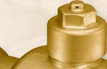


175 Ball Valves Used in supermarket and refrigeration applications Complete range, reliable, vented cap long life valves 8

176 Ball Valves - Bi-Flow Ball Valves Parker Bi-Flow Ball Valves are available in a range of Inch Sizes from 1/4" to 4.1/8", metric from mm but also in Schraeder valve version. Cap: The brass cap thread broached in three places to ensure adequate venting when the cap is removed. The cap is also tagged to accommodate wiring and sealing where legislation demands. Ball features: A small hole in one sealing face of the ball prevents refrigerant being locked within the ball when closed. It also allows the ball to exert a greater force against the Teflon Ball seal when closed, giving greater close-off security. Applications: Supermarkets Refrigeration Benefits: Compact Reliable Vented cap Long life Complete range from 1/4" to 4.1/8" Metric from 6 mm to 108 mm reserves the right to change this document without notice. For all requests, consult your nearest Wholesaler or contact us on: 176 RACE Catalogue R & A/C gal-1a/uk - Ed. November 2011
177 Valve Dimensions Nomenclature O. D. = Outside Diameter. BV6MM = Ball valve for O.D. tube 6 mm. BV21SV = Ball valve for O.D. tube 21/8 inches, so 2" 5/8 OD with Schraeder Valve (SV). Specifications and Dimensions Metric Size Metric Reference For Tube O.D. mm Bore Diameter mm L mm C mm H mm kv Value m 3 /h BV6MM BV8MM BV10MM BV10MMSV BV12MM BV12MMSV BV15MM BV15MMSV BV5 (ex BV16MM) BV16MMSV BV18MM BV18MMSV BV22MM BV22MMSV BV28MM BV28MMSV BV11 (ex BV35MM) BV35MMSV BV42MM BV42MMSV BV17 (ex BV54MM) BV54MMSV BV64MM BV64MMSV BV76MM BV76MMSV Weight g BV89MM BV89MMSV BV108MM BV108MMSV RACE Catalogue R & A/C gal-1/uk - Ed. November 2011
178 Valve Dimensions Specifications and Dimensions Inches Inches Reference For Tube O.D. Inch Bore Diameter mm L mm C mm H mm kv Value m 3 /h BV2 1/4" BV3 3/8" BV3SV 3/8" BV4 1/2" BV4SV 1/2" BV5 5/8" BV5SV 5/8" BV6 3/4" BV6SV 3/4" BV7 7/8" BV7SV 7/8" BV9 1 1/8" BV9SV 1 1/8" BV11 1 3/8" BV11SV 1 3/8" BV13 1 5/8" BV13SV 1 5/8" BV17 2 1/8" BV17SV 2 1/8" BV21 2 5/8" BV21SV 2 5/8" BV25 3 1/8" Weight g BV29 3 5/8" BV33 4 1/8" For all requests, consult your nearest Wholesaler or contact us on: 178 RACE Catalogue R & A/C gal-1a/uk - Ed. November 2011
179 Valve Dimensions Specifications and Dimensions Working Range Safe working pressure: 45 barg Operating Temperature: -40 C to +150 C Indicator disc A Groove G Hole a Refrigerant Compatibility Compatible for use with all HFC and HCFC refrigerants. Valves are available could also be equipped with Schraeder valves. For more information on CO2, please contact us. Pressure compensating hole b Cap Wrench size Ball Groove G H Ø D C L Replacement Caps Cap references are also suitable for reference equipped with Schraeder Valve Cap for BV PN From To BV00501 BV6MM-BV2 BV12MM-BV4 BV00502 BV15MM-BV5 BV18MM-BV6 BV00503 BV22MM-BV7 BV35MM-BV11 BV00504 BV42MM-BV13 BV54MM-BV17 BV00505 BV64MM-BV21 BV108MM-BV33 For all requests, consult your nearest Wholesaler or contact us on: RACE Catalogue R & A/C gal-1a/uk - Ed. November 2011
180 Notes For all requests, consult your nearest Wholesaler or contact us on: 180 RACE Catalogue R & A/C gal-1a/uk - Ed. November 2011


181 9 Filters Driers Filters driers contributing to maintain the cleanliness of circuits
 is made with of combination of ester acid and alcohol.")

. Molecular sieve allows to keep a very low content of the moisture in the system.")


182 Filters Driers HFC refrigerant and their associated oils are very hygroscopic more than CFC or HCFC and their mineral or alkyl benzene oils. The polyol esther oil (POE) is made with of combination of ester acid and alcohol. If a moisture content is more important than 75ppm the mixture oil and water generates acid and alcohol, it is a reversible processes. At the same time presence of moisture into the system also generates acid. To prevent risk of acids generation chemical products are used: Molecular sieve is used to trap moisture in channels of 3Å size. Channels can trap water molecules only (water molecule are smallest than refrigerant molecule). Molecular sieve allows to keep a very low content of the moisture in the system. The molecular sieve efficiency is higher than activated alumina, roughly 3 times more. Activated alumina is used to trap acid from the refrigerant and/or oil and moisture with less efficiency than molecular sieve. These chemical products are present in the filter driers and we recommend to use an efficient filter drier in the liquid line (WEU / Catch-All ) of the thermodynamic system. The filters driers can be sealed, for small systems, or flanged for big systems. Chemical components can be filled in a compact bead or in compacted solid cores. Compact bead allows to fill the highest part of the internal volume of the shell. Solid cores used same chemical components moulded with a resin. This kind of filter drier is suitable for mobile system. Chemical components inside filter driers are used alone or blended, it depends of the machine (rack, chiller etc ) and of the kind of refrigerants used. A product manufactured in a factory that nobody is supposed to open the circuit, (ice machine, chiller etc.) can be delivered with a filter drier made with 100% of molecular sieve. Product is made in the respect of the rules, dehydrated and delivered with an overpressure to avoid any possibility of air introduced inside the product. In the other case when the unit is made in a factory is supposed to be serviced, as a condensing unit where piping and evaporator are connected, the best way is to set a filter drier with a blend of molecular sieve and activated alumina. Indeed moisture can set into the circuit due to duration of the installation or a non complete vacuum operation before starting up it could generate acids. Presence of activated alumina allows the retention of acids quickly and ensure a long life of the system. The filters driers work in only one direction and are installed in the liquid line. In a reversible system like a heat pump or refrigeration unit with a defrosting by reversible cycle, the refrigerant can have a flow in two directions. A special Bi-flow filter is necessary, it is made with two special valves plates at each ends and is capable to trap moisture, dirt and acids in two directions without the possibility to release particles. The efficiency of filters driers can be checked by the addition of a sight glass with moisture indicator just after. When the filter drier is clogged, few bubbles could appear in the sight glass and the temperature of the outlet is generally lower than in the inlet. For all requests, consult your nearest Wholesaler or contact us on: 182 RACE Catalogue R & A/C gal-1a/uk - Ed. November 2011
183 Index Filtration Dehydration 9 Filters Driers WEU / C Series Catch-All CoresnReplaceable Filters Shells VS Bi-Flow Filters Driers V2A / HPC Series Catch-All Filters Driers with Sight Glasses WSG Cleaning Decontamination Cleaning Suction Filters WSF - SF Series Catch-All Suction Filters Driers C Series Catch-All Burn Out Filters WSL / C Series Catch-All Burn Out Bi-Flow Filters HPC-HH Series Catch-All Corrections Factors for Filters Driers reserves the right to change this document without notice. For all requests, consult your nearest Wholesaler or contact us on: 183 RACE Catalogue R & A/C gal-1a/uk - Ed. November 2011

184 Filter Drier Compact bead WEU WorldSeries TM WorldSeries TM WEU liquid line filters driers ensure protection of refrigeration and air-conditioning systems from moisture, acids, and solid particles. WEU liquid filter driers contain 100% 3Å molecular sieve in compacted bead for a maximum efficiency of dehydration. WEU are suitable for all CFC, HCFC and HFC refrigerant and associated oils. WEU liquid line filters driers contribute to maintain the cleanliness of circuits, the efficiency of the systems and prolongs their life expectancies. This reduces the cost of functioning. Benefits Max Working Pressure Temperature Range 45 barg (652 psig) -40 C to +80 C Leak Testing: 100% Helium leak tested Coating: Polyester coating giving protection to 500 hours salt spray Filtration: 20 microns Approvals: UL file no. SA PED 97/23/EC - article 3.3 The physical size of the WEU filters driers range allows the product to be manufactured under the PED category (art. 3.3) which does not require the "CE" marking. Technical Data WEU Drying Capacity - kg of refrigerant* WEU Series R134a 24 C 52 C R404A 24 C 52 C R407C 24 C 52 C R410A 24 C 52 C R C 52 C WEU WEU WEU WEU WEU WEU WEU (*) Drying capacity is the results of standard tests before and after drying from 1050ppm to 50ppm For all requests, consult your nearest Wholesaler or contact us on: 184 RACE Catalogue R & A/C gal-1a/uk - Ed. November 2011
185 Technical Data WEU Flare (SAE) Connections Female/Male 9 Part Number Connections SAE (1) Liquid capacity in accordance with ARI standard Te = 15 C, Tc = 30 C, Δp = 0.07 bar (1 psig) WEU Flare (SAE) Connections Female/Male Flow Capacity (kw) (1) Dimensions (mm) Weight R134a R404A R507 R407C R410A R22 L B D1 D2 kg WEU032F 1/4" WEU052F 1/4" WEU053F 3/8" WEU082F 1/4" WEU083F 3/8" WEU084F 1/2" WEU162F 1/4" WEU163F 3/8" WEU164F 1/2" WEU165F 5/8" WEU303F 3/8" WEU304F 1/2" WEU305F 5/8" WEU414F 1/2" WEU415F 5/8" Part Number Connections SAE (1) Liquid capacity in accordance with ARI standard. Te = -15 C, Tc = 30 C, Δp = 0.07 bar (1 psig). Other working conditions see pages 223 to 225. Flow Capacity (kw) (1) Dimensions (mm) Weight R134a R404A R507 R407C R410A R22 L B D1 D2 kg WEU032FM 1/4" WEU052FM 1/4" WEU053FM 3/8" WEU083FM 3/8" WEU162FM 1/4" For all requests, consult your nearest Wholesaler or contact us on: 185 RACE Catalogue R & A/C gal-1a/uk - Ed. November 2011
186 Technical Data WEU Solder (ODF) Connections in inches Part Number Connections ODF Flow Capacity (kw) (1) Dimensions (mm) Weight R134a R404A R407C R410A L A B D1 D2 kg R507 R22 WEU032S 1/4" WEU052S 1/4" WEU053S 3/8" WEU082S 1/4" WEU083S 3/8" WEU084S 1/2" WEU162S 1/4" WEU163S 3/8" WEU164S 1/2" WEU165S 5/8" WEU303S 3/8" WEU304S 1/2" WEU305S 5/8" WEU307S 7/8" WEU414S 1/2" WEU415S 5/8" WEU417S 7/8" WEU754S 1/2" WEU755S 5/8" WEU756S 3/4" WEU757S 7/8" WEU759S 1"1/ (1) Liquid capacity in accordance with ARI standard Te = 15 C, Tc = 30 C, Δp = 0.07 bar (1 psig) Other working conditions see pages 223 to 225. For all requests, consult your nearest Wholesaler or contact us on: 186 RACE Catalogue R & A/C gal-1a/uk - Ed. November 2011
187 WEU Solder (ODF) Connections in metric 9 Part Connections Flow Capacity (kw) (1) Dimensions (mm) Weight Number ODF R134a R404A R407C R410A L A B D1 D2 kg R507 R22 WEU0306MMS 6 mm WEU0506MMS 6 mm WEU0510MMS 10 mm WEU0806MMS 6 mm WEU0810MMS 10 mm WEU0812MMS 12 mm WEU1606MMS 6 mm WEU1610MMS 10 mm WEU1612MMS 12 mm WEU165S 16 mm WEU3010MMS 10 mm WEU3012MMS 12 mm WEU305S 16 mm WEU4112MMS 12 mm WEU415S 16 mm WEU755S 16 mm (1) Liquid capacity in accordance with ARI standard Te = 15 C, Tc = 30 C, Δp = 0.07 bar (1 psig) Other working conditions see pages 223 to 225. For all requests, consult your nearest Wholesaler or contact us on: 187 RACE Catalogue R & A/C gal-1a/uk - Ed. November 2011

 -40 C up to +66 C Leak Testing: 45 bar in a pool Coating: Polyester Winter Gray 10-7069 is a U.")
188 Filter Drier solid Core C Series Catch-All Catch-All C Series liquid line filters driers ensure the protection of the refrigeration and air-conditioning systems from moisture, acids, and solid particles. Catch-All liquid filter driers contain unique moulded porous core, consisting of a blend of highly effective desiccants. They are unexcelled in moisture removal and acid retention. The famous moulded porous core of the Catch-All Filter-Drier performs these vital functions and improves the life cycle of all thermodynamic systems. Benefits Max Working Pressure Temperature Range 44.8 barg (650 psig) -40 C up to +66 C Leak Testing: 45 bar in a pool Coating: Polyester Winter Gray is a U.L recognized high gloss epoxy powder coating Filtration: 20 microns Approvals: UL file no. SA-1756A & B. PED 97/23/EC - article 3.3 The physical size of the C Series Catch-All filter driers range allows the product to be manufactured under the PED category (art.3.3) which does not require the "CE" marking. Technical Data Catch-All Drying capacity - kg of refrigerant* C Series R134a R404A R507 R407C R410A R C 52 C 24 C 52 C 24 C 52 C 24 C 52 C 24 C 52 C C C C * Drying capacity is the result of standard tests before and after drying from 1050 ppm to 50 ppm. C C C C (*) Drying capacity is the result of standard tests before and after drying from 1050ppm to 50ppm For all requests, consult your nearest Wholesaler or contact us on: 188 RACE Catalogue R & A/C gal-1a/uk - Ed. November 2011


189 Technical Data Catch-All Flare (SAE) Connections 9 Part Number C Series Connections SAE R22 Flow Capacity (kw) (1) Dimensions (mm) Weight R134a R404A R410A L D1 kg R407C R C-032 1/4" C-032-FM 1/4" C-033 3/8" C-052 1/4" C-052-FM 1/4" C-053 3/8" C-082 1/4" C-083 3/8" C-084 1/2" C-162 1/4" C-163 3/8" C-164 1/2" C-165 5/8" C-303 3/8" C-304 1/2" C-305 5/8" C-414 1/2" C-415 5/8" (1) Liquid capacity in accordance with ARI standard. Te = -15 C, Tc = 30 C, Δp = 0.07 bar (1 psig). FM= Female / Male. Other working conditions see pages 223 to 225. For all requests, consult your nearest Wholesaler or contact us on: 189 RACE Catalogue R & A/C gal-1a/uk - Ed. November 2011
 (1) Dimensions (mm) Weight R134a R404A R410A L A D1 kg R407C R507 400052 C-032-S 1/4\" 5.26 4.57 3.52 4.92 97 77 44 0.227 400001 C-033-S 3/8\" 13.40 12.30 9.14 13.00 99 77 44 0.")

190 Technical Data Catch-All ODF Solder Connections Part Number C Series Connections ODF (1) Liquid capacity in accordance with ARI standard. Te = -15 C, Tc = 30 C, Δp = 0.07 bar (1 psig). R22 Flow Capacity (kw) (1) Dimensions (mm) Weight R134a R404A R410A L A D1 kg R407C R C-032-S 1/4" C-033-S 3/8" C-052-S 1/4" C-053-S 3/8" C-082-S 1/4" C-083-S 3/8" C-084-S 1/2" C-162-S 1/4" C-163-S 3/8" C-164-S 1/2" C-165-S 5/8" C-303-S 3/8" C-304-S 1/2" C-305-S 5/8" C-307-S 7/8" C-414-S 1/2" C-415-S 5/8" C-417-S 7/8" C-419-S 1-1/8" C-607-S 7/8" C-609-S 1-1/8" For all requests, consult your nearest Wholesaler or contact us on: 190 RACE Catalogue R & A/C gal-1a/uk - Ed. November 2011

191 Replaceable filter shells VS K-Line 9 K-LINE VS replaceable filter shells ensure protection of refrigeration and air-conditioning systems from moisture, acids, and solid particles in liquid line or/and the suction line. VS filter shells and associated cores allow answering to all problem of circuit s contamination for best protection of compressors and components. An innovative conical core holder used in suction line allows minimizing pressure drop. The very large surfaces of the conical or cylindrical filters create a very low pressure drop comparatively to the other competitors. VS filter shells are delivered with steel or copper connections in inches and metric and are suitable for both suction and liquid lines. Steel connections are suitable for installations made with steel or stainless steel pipes and of course for copper pipes. Copper connections are suitable for copper piping and can be braze with low content of silver alloy or with copper phosphoric alloy. VS shells and associated cores holders and cores guaranties cleanness and performances of all systems. This contributes to reduce operation and maintenance costs. Benefits Max Working Pressure Temperature Range 35 barg (VS) / 46 barg (VSHP) -40 C to +80 C Leak Testing: 100% Helium leak tested Coating: Polyester coating giving protection to 500 hours salt spray Filtration: Approvals: 20 microns PED 97/23/EC - article I Liquid capacities are published in accordance with ARI standard Te = -15 C, Tc = 30 C, Δp = 0.07 bar. Suction capacities are published in accordance with ARI standard Te = -4.4 C, Tc = 32 C, Δp = 0.07 bar. Other working conditions see pages 223 to 225. VS Series Number of core(s) For all requests, consult your nearest Wholesaler or contact us on: Core holders Cylindrical Conical VS48xx 1 ASK1 ASKSL VS96xx 2 ASK2 ASKSL + ASK1 VS144xx 3 ASK3 ASKSL + ASK2 VS192xx 4 ASK4 ASKSL + SK3 191 RACE Catalogue R & A/C gal-1a/uk - Ed. November 2011
192 Technical Data VS Shells With STEEL CONNECTIONS for liquid line - INCHES Part Connections Flow Capacity (kw) Dimensions (mm) Number ODF R134a R404A R407C R410A R22 A B C D E F G L R507 VS485 5/8" VS487 7/8" VS /8" VS /8" VS /8" VS /8" VS /8" VS /8" VS967 7/8" VS /8" VS /8" VS /8" VS /8" VS /8" VS /8" VS /8" VS /8" VS /8" VS /8" VS /8" VS /8" VS /8" VS /8" VS /8" VS /8" VS /8" For all requests, consult your nearest Wholesaler or contact us on: 192 RACE Catalogue R & A/C gal-1a/uk - Ed. November 2011
193 Technical Data VS Shells With STEEL CONNECTIONS for liquid line - METRIC 9 Part Connections Flow Capacity (kw) Dimensions (mm) Number ODF R134a R404A R407C R410A R22 A B C D E F G L R507 VS mm VS4828mm 28 mm VS mm VS4842mm 42 mm VS mm VS4864mm 64 mm VS9628mm 28 mm VS mm VS9642mm 42 mm VS mm VS14428mm 28 mm VS mm VS14442mm 42 mm VS mm VS mm VS19242mm 42 mm VS mm For all requests, consult your nearest Wholesaler or contact us on: 193 RACE Catalogue R & A/C gal-1a/uk - Ed. November 2011
194 Technical Data VS Shells High Pressure With STEEL CONNECTIONS for liquid line - INCHES & METRIC Part Connections Flow Capacity (kw) Dimensions (mm) Number ODF R134a R404A R407C R410A R22 A B C D E F G L R507 VS485HP 5/8" VS487HP 7/8" VS489HP 1-1/8" VS4811HP 1-3/8" VS4813HP 1-5/8" VS967HP 7/8" VS969HP 1-1/8" VS9611HP 1-3/8" VS9613HP 1-5/8" VS485HP 16 mm VS4828mmHP 28 mm VS4811HP 35 mm VS4842mmHP 42 mm VS9628mmHP 28 mm VS9611HP 35 mm VS9642mmHP 42 mm For all requests, consult your nearest Wholesaler or contact us on: 194 RACE Catalogue R & A/C gal-1a/uk - Ed. November 2011
195 Technical Data VS Shells With COPPER CONNECTIONS for liquid line - INCHES 9 Part Connections Flow Capacity (kw) Dimensions (mm) Number ODF R134a R404A R407C R410A R22 A B C D E F G L R507 VS485S 5/8" VS487S 7/8" VS489S 1-1/8" VS4811S 1-3/8" VS4813S 1-5/8" VS4817S 2-1/8" VS4821S 2-5/8" VS967S 7/8" VS969S 1-1/8" VS9611S 1-3/8" VS9613S 1-5/8" VS9617S 2-1/8" VS1449S 1-1/8" VS14411S 1-3/8" VS14413S 1-5/8" VS14417S 2-1/8" VS1929S 1-1/8" VS19211S 1-3/8" VS19213S 1-5/8" VS19217S 2-1/8" VS19221S 2-5/8" For all requests, consult your nearest Wholesaler or contact us on: 195 RACE Catalogue R & A/C gal-1a/uk - Ed. November 2011
196 Technical Data VS Shells With COPPER CONNECTIONS for liquid line - METRIC Part Number Connections ODF Flow Capacity (kw) Dimensions (mm) R134a R404A R407C R410A R22 A B C D E F G L R507 VS485S 16 mm VS4828mmS 28 mm VS4811S 35 mm VS4842mmS 42 mm VS4817S 54 mm VS9628mmS 28 mm VS9611S 35 mm VS9642mmS 42 mm VS9617S 54 mm VS14428mmS 28 mm VS14411S 35 mm VS14442mmS 42 mm VS14417S 54 mm VS19211S 35 mm VS19242mmS 42 mm VS19217S 54 mm For all requests, consult your nearest Wholesaler or contact us on: 196 RACE Catalogue R & A/C gal-1a/uk - Ed. November 2011
197 Technical Data VS Shells With STEEL CONNECTIONS for suction line with CONICAL FILTER (ASKSL) 9 Part Connections Flow Capacity (kw) Dimensions (mm) Number ODF R134a R404A R407C R410A R22 A B C D E F G L R507 VS489CF 1-1/8" VS4811CF 1-3/8" VS4813CF 1-5/8" VS4817CF 2-1/8" VS4821CF 2-5/8" VS4825CF 3-1/8" VS9613CF 1-5/8" VS9617CF 2-1/8" VS9621CF 2-5/8" VS9625CF 3-1/8" VS4811CF 35 mm VS4842mmCF 42 mm VS4817CF 54 mm VS9642mmCF 42 mm VS9617CF 54 mm See drawings page 193 VS Shells With COPPER CONNECTIONS for suction line with CONICAL FILTER (ASKSL) Part Connections Flow Capacity (kw) Dimensions (mm) Number ODF R134a R404A R407C R410A R22 A B C D E F G L R507 VS489SCF 1-1/8" VS4811SCF 1-3/8" VS4813SCF 1-5/8" VS4817SCF 2-1/8" VS4821SCF 2-5/8" VS9613SCF 1-5/8" VS9617SCF 2-1/8" VS4811SCF 35 mm VS4842mmSCF 42mm VS4817SCF 54 mm VS9642mmSCF 42mm VS9617SCF 54 mm See drawings page 195 For all requests, consult your nearest Wholesaler or contact us on: 197 RACE Catalogue R & A/C gal-1a/uk - Ed. November 2011


198 ASK4 ASK3 ASK2 ASK1 ASKSL ASK Conical fi lter for suction use For all requests, consult your nearest Wholesaler or contact us on: 198 RACE Catalogue R & A/C gal-1a/uk - Ed. November 2011


199 VS / Gores VS / Gold 9 offers a very large range of cores corresponding to all situations for help the user to maintain system s cleanness and efficiency. This is a guarantee of cost reduction for maintenance and repair. First Operation VS32H: Dedicated to suction line fi lter shell with an innovative conical fi lter to reduce pressure drop at compressor suction. It is a blend of molecular sieve and activated alumina for a great moisture adsorption and high capacity of acid retention. It must be used in a suction line fi lter shell with ASKSL conical fi lter. VS48H: "The" standard core for the liquid line made with a blend of molecular sieve and activated alumina. This core has high capacity of dehydration and acid retention. It can be used in a suction line fi lter shell with ASK cylindrical fi lter. VS48XH: The highest moisture capacity available from a 48 inch cube core. It is made with 100% of 3Å molecular sieve in a good proportion of biding agent to have very high capacity of moisture adsorption. VS48XH is the best core for installation where HFC refrigerant and associated oil are used, which are very hygroscopic. It is the perfect choice for chillers with shell and tubes or brazed plate evaporators. It doesn t have a potential for hydrolysis or bi-polar attraction of lubricant additives. It can be used in both liquid and suction line with ASK cylindrical fi lter. VS48F: The felt element is designed for use in suction line will give effective fi ltration and compressor protection during start up and commissioning periods. For best results the It must be used in conjunction with the ASKSL conical fi lter. This allows small pressure drop and then protects compressors. Temporary use only. RPE-48-BD: The reinforced felt element designed for the suction line during the commissioning period and after. The felt element have an external stainless steel screen to prevent from destruction in case of too big pressure drop due to clogging. It with ASK cylindrical fi lter can replace VS48F after commissioning period. Maintenance and Repair VS48SC: dedicated to cleaning, decontamination or after compressor burn out. It uses an optimum blend of molecular sieve, activated alumina and activated charcoal. This allows to trap acid, sludge and wax and of course moisture. It must be used in the same time in both suction and liquid line for decreasing quickly acid content and to minimize the pressure drop in suction fi lter shell. Temporary use only. RCW48 "GOLD": This core has very high capacity of water retention. Especially made for refrigeration and air conditioning systems which work with HFC and POE lubricants. Thoses cores are the good choice after damage in water evaporator or when moisture content is very high. They can be used in both liquid and suction line. Operating temperature range: -45 C to 65 C For all requests, consult your nearest Wholesaler or contact us on: 199 RACE Catalogue R & A/C gal-1a/uk - Ed. November 2011


200 Technical Data VS32H 48 Series Part Number Dimensions (mm) Filtration Surface Height A Ø External B Ø Internal C (cm 2 ) VS32H VS48H VS48XH VS48F RPE-48-BD VS48SC RCW-48-GOLD Drying Capacity - kg of refrigerant* Part Number R 22 R134a R404A / R507 R407C R410A 24 C 52 C 24 C 52 C 24 C 52 C 24 C 52 C 24 C 52 C VS32H VS48H VS48XH VS48SC RCW-48-GOLD * Drying capacity is the result of standard tests before and after drying from 1050 ppm to 50 ppm. For all requests, consult your nearest Wholesaler or contact us on: 200 RACE Catalogue R & A/C gal-1a/uk - Ed. November 2011


201 Bi-Flow filter drier V2A WorldSeries TM 9 WorldSeries TM V2A Bi-Flow liquid line filters driers ensure protection of reversible refrigeration, air conditioning and heat pumps systems from moisture, acids, and solid particles. V2A Bi-Flow liquid line filter drier is dedicated to all reversible systems requiring high degree of protection against humidity and its consequences. Two check valves in both end side, made in rubber, ensure liquid flow in two directions without possibility of dirt, trapped inside the core, being discharge into the circuit. The special design of check valve minimise the pressure drop into V2A Bi-Flow liquid line filter drier, this allows optimisation of the COP for the heat pump. WorldSeries TM V2A Bi-Flow liquid line filters driers allow to simplify the installation of reversible systems and are adapted to high efficiency heat pumps. Benefits Max Working Pressure Temperature Range 45 bar (652 psig) 40 C to +80 C Leak Testing: 100% Helium leak tested with Nitrogen pressure test V2A Paint: Polyester grey coating (RAL 7037) giving protection to 500 hours salt spray. Filtration: Approvals: 20 microns UL file no SA1906 PED 97/23/EC - article 3.3 The physical size of the V2A liquid line filters driers range allows the product to be manufactured under the PED category (art.3.3) which does not require "CE" marking. For all requests, consult your nearest Wholesaler or contact us on: 201 RACE Catalogue R & A/C gal-1a/uk - Ed. November 2011
202 Technical Data V2A Drying Capacity - kg of refrigerant* V2A Series R134a R404A R407C R410A R C 52 C 24 C 52 C 24 C 52 C 24 C 52 C 24 C 52 C V2A V2A * Drying capacity is the results of standard tests before and after drying from 1050 ppm to 50 ppm V2A Liquid Refrigerant Holding - Capacity Grams at 40 C V2A Series R134a R404A R407C R410A R 22 V2A V2A V2A Flow capacity in kw Part number Connection Size Flow Capacity (kw)(1) Dimensions (mm) Weight R134a R410A L D2 Series (2) R507 R22 V2A SAE ODF R404A R407C A B D1 Kg V2A083F 3/8" V2A083S - 3/8" V2A084F 1/2" V2A084S - 1/2" V2A163F 3/8" V2A163S - 3/8" V2A164F 1/2" V2A164S - 1/2" V2A165F 5/8" V2A165S - 5/8" 16 mm (1) Liquid capacity in accordance with ARI standard - Te = -15 C, Tc = 30 C, Δp = 0.07 bar (1 psig) Other working conditions see pages 00 & 00 (2) F = Flare (SAE), S = Solder V2A Solder V2A Flare L A B L B For all requests, consult your nearest Wholesaler or contact us on: Ø D1 Ø D2 Ø D1 Ø D2 202 RACE Catalogue R & A/C gal-1a/uk - Ed. November 2011


203 Bi-Flow filter drier HPC Series Catch-All 9 Catch-All Bi-Flow liquid line filters driers ensure the protection of reversible systems as refrigeration, air-conditioning and heat pumps from moisture, acids, and solid particles. The special design of the valves plates ensure liquid flow in two directions without possibility of dirt trapped inside the core being discharge into the circuit. The design of cores and choice of the chemical components insure perfect result with small pressure drop. Efficiency and life of all reversible air conditioning 2 or 3 tubes systems as well as heat pumps can be improved with HPC Catch-All filters driers. Benefits Max Working Pressure Temperature Range 44.8 bar (650 psig) -40 C up to +66 C Leak Testing: 45 bar in a pool Catch-Call Paint: Winter Gray is an U.L recognised high gloss epoxy powder coating. Filtration: 20 microns Approvals: PED 97/23/EC - article 3.3 UL file no. SA A & B The physical size of the Catch-All Bi-flow filter drier range allows the product to be manufactured under the PED category (art.3.3) which does not require the "CE" marking. For all requests, consult your nearest Wholesaler or contact us on: 203 RACE Catalogue R & A/C gal-1a/uk - Ed. November 2011
 Connections Flow capacity (kw) (1) Dimensions (mm) Weight SAE ODF R22 R134a R407C R404A R507 R410A L A D1 kg 404080 HPC-103 3/8\" 17.6 16.2 11.8 17.2 171.5 76 0.")


204 Technical Data HPC Flow capacity in kw Part Number Part Number (1) Liquid capacity in accordance with ARI standard. Te = -15 C, Tc = 30 C, Δp = 0.07 bar (1 psig) Connections Flow capacity (kw) (1) Dimensions (mm) Weight SAE ODF R22 R134a R407C R404A R507 R410A L A D1 kg HPC-103 3/8" HPC-103-S 3/8" HPC-104 1/2" HPC-104-S 1/2" HPC-105 5/8" HPC-105-S 5/8" HPC-163 3/8" HPC-163-S 3/8" HPC-164 1/2" HPC-164-S 1/2" HPC-165 5/8" HPC-165-S 5/8" HPC-304 1/2" HPC-304-S 1/2" HPC-305 5/8" HPC-305-S 5/8" HPC-306-S 3/4" HPC-307-S 7/8" The fi lter drier operate in either fl ow direction, the refrigerant go across the cores from the external face to the internal space. HPC Catch-All Bi-fl ow fi lters driers do not release the dirt collected in one direction when the fl ow direction reverses. For all requests, consult your nearest Wholesaler or contact us on: 204 RACE Catalogue R & A/C gal-1a/uk - Ed. November 2011
205 Filter drier with sight glass WSG WorldSeries TM 9 WorldSeries TM WSG liquid line filters driers and sight glasses ensure: Protection of refrigeration and air-conditioning systems from moisture, acids, and solid particles. Visual control of flow, dryness and color of liquid refrigerant. WSG liquid filters driers and sight glass contain 100% molecular sieve in compacted bead for a maximum efficiency of dehydration. This 2 in 1 product reduces the installation time for the user and minimize the risk of leakage. We recommend to protect the glass by calorie discharger TB2 Thermal BlockTM or to wrap with a damp cloth when WSG with solder connections are used. 2 in 1 WSG product minimize installation work, risk of leakage and optimize system s size. Benefits Max Working Pressure Temperature Range 45 barg (652 psig) -40 C to +80 C Leak Testing: 100% helium leak tested Coating: Polyester coating giving protection to 500 hours salt spray. Filtration: 20 microns Approvals: UL file no. SA PED 97/23/EC - article 3.3 The physical size of the WSG filters driers and sight glasses range allows the product to be manufactured under the PED category (art.3.3) which does not require the "CE" marking. For all requests, consult your nearest Wholesaler or contact us on: 205 RACE Catalogue R & A/C gal-1a/uk - Ed. November 2011


206 Technical Data WSG Drying Capacity - kg of refrigerant* WSG Series R134a R404A R407C R410A R C 52 C 24 C 52 C 24 C 52 C 24 C 52 C 24 C 52 C WSG WSG WSG WSG * Drying capacity is the results of standard tests before and after drying from 105 0ppm to 50 ppm WSG Liquid Refrigerant Holding - Capacity Grams at 40 C WSG Series R134a R404A R407C R410A R 22 WSG WSG WSG WSG For all requests, consult your nearest Wholesaler or contact us on: 206 RACE Catalogue R & A/C gal-1a/uk - Ed. November 2011


207 Technical Data WSG Flare (SAE) Connections 9 Part Number Connection Size Flow Capacity (kw) * Dimensions (mm) Weight SAE R134a R404A R507 R407C R410A R22 L A B D1 D2 Kg WSG052F 1/4" WSG053F 3/8" WSG082F 1/4" WSG083F 3/8" WSG084F 1/2" WSG162F 1/4" WSG163F 3/8" WSG164F 1/2" WSG165F 5/8" WSG303F 3/8" WSG304F 1/2" WSG305F 5/8" * Liquid capacity in accordance with ARI standard. Te = -15 C, Tc = 30 C, Δp = 0.07 bar (1 psig). Other working conditions see pages 223 to 225. L B Ø D1 Ø D2 For all requests, consult your nearest Wholesaler or contact us on: 207 RACE Catalogue R & A/C gal-1a/uk - Ed. November 2011


208 Technical Data WSG Solder ODF Connections Part Number Connection Size Flow Capacity (kw) * Dimensions (mm) Weight ODF R134a R404A R507 R407C R410A R22 L A B D1 D2 Kg WSG053S 3/8" WSG083S 3/8" WSG084S 1/2" WSG163S 3/8" WSG164S 1/2" WSG165S 5/8" WSG304S 1/2" WSG305S 5/8" WSG307S 7/8" WSG0510MM 10 mm WSG0810MM 10 mm WSG0812MM 12 mm WSG1612MM 12 mm WSG165S 16 mm WSG305S 16 mm WSG307S18MM 18 mm * Liquid capacity in accordance with ARI standard. Te = -15 C, Tc = 30 C, Δp = 0.07 bar (1 psig). Other working conditions see pages 223 to 225. L B A Ø D1 Ø D2 For all requests, consult your nearest Wholesaler or contact us on: 208 RACE Catalogue R & A/C gal-1a/uk - Ed. November 2011


209 Cleaning After Starting Up During the installation moisture can be introduced into the system. 9 When copper pipes are brazed without an internal flow of nitrogen, copper oxid will be produced. The copper oxid deposit is unstuck from the piping by POE oil. During the commissioning period carbon deposit can clog expansion valve or suction line accumulator and can pollute the oil. To prevent thoses damages of oil pollution we recommend the installation of a suction filter at the inlet of the compressor or at the inlet of the suction accumulator. Suctions filters are equipped with one or two Schrader valves used to measure the pressure loss and could have an internal By-Pass Relief valve. For all requests, consult your nearest Wholesaler or contact us on: 209 RACE Catalogue R & A/C gal-1a/uk - Ed. November 2011
210 Cleaning suction filter WSF Series WorldSeries TM WorldSeries TM WSF cleaning suction filters protect compressors by removing all particles from the circuit of f refrigeration and air-conditioning. Particles can be carbon deposit, metallic shaving, resulting from the wear of the compressor or of the piping installation. WSF cleaning suction filters must be installed between the evaporator and the suction accumulator or the compressor. WSF cleaning suction filters can be used in the heat pumps or reversible systems and must be installed between the 4 way valve and the suction valve of the compressor. Benefits Max Working Pressure Temperature Range 20.8 bar (302 psig) -40 C up to +80 C Leak Testing: 100% Helium leak tested WSF Paint: Polyester grey coating (RAL 7037) giving protection to 500 hours salt spray. Filtration: 20 microns Approvals: PED 97/23/EC - article 3.3 The physical size of the WSF suction filters range allow the product to be manufactured under the PED category (art.3.3) which does not require the "CE" marking. For all requests, consult your nearest Wholesaler or contact us on: 210 RACE Catalogue R & A/C gal-1a/uk - Ed. November 2011

.")
211 Technical Data Part Number Connections ODF Suction Flow Capacity(kW)* Dimensions (mm) Weight kg R22 R134a R404A R407C R410A L A B D1 D2 WSF5S 5/8" (16mm) WSF6S 3/4" WSF7S 7/8" WSF9S 1-1/8" WSF11S 1-3/8" (35mm) WSF13S 1-5/8" * Suction capacity in accordance with ARI standard. Te = 4.4 C, Tc = 32 C, Δp = 0.07 bar (1 psig). For all requests, consult your nearest Wholesaler or contact us on: 211 RACE Catalogue R & A/C gal-1a/uk - Ed. November 2011

212 Suction filter SF Catch-All Catch-All SF suction line filters protect compressors by removing all particles from refrigeration and air-conditioning circuits. Particles can be carbon deposit, metallic shaving, resulting from wear of compressor or of piping installation. Catch-All SF suction line filter must be installed between evaporator and suction accumulator or compressor. In case of reversible system Catch-All SF suction filters must be installed between the 4 way valve and compressor s suction valve. Catch-All SF suction line filter can be equipped with 1Shraeder valve allowing to check pressure drop. Few models of Catch-All SF suction line filters have a by-pass relief feature to prevent an excessive pressure drop to optimise compressor protection of the overheating. Catch-All SF suction line filter is easy to install in suction line and can correspond to all request of users. An innovative By-pass is the key of your success. Benefits Max Working Pressure Temperature Range 44.8 bar (650 psig) -40 C up to +66 C Leak Testing: Catch-All Paint: 45 bar in a pool Winter Gray is a U.L. recognized high gloss epoxy powder coating Filtration: 20 microns Approvals: PED 97/23/EC - article 3.3 UL file no. SA-1756A & B The physical size of the Catch-All suction filter drier range allow the product to be manufactured under the PED category (art.3.3) which does not require the "CE" marking. For all requests, consult your nearest Wholesaler or contact us on: 212 RACE Catalogue R & A/C gal-1a/uk - Ed. November 2011


213 Technical Data Part Number Part Number Connections Size By- Pass Access Valve Suction Flow Capacity(kW)* Dimensions (mm) Weight kg SAE ODF R22 R134a R22 R134a R404A R407C R410A L A D1 R SF-283-F 3/8" SF-114-F 1/2" SF-114-1/2" SF-115-F 5/8" SF-115-5/8" SF-285-T - 5/8" SF-286-T - 3/4" SF-287-T - 7/8" SF-289-T - 1-1/8" SF-489-T - 1-1/8" SF-4811-T - 1-3/8" SF-4813-T - 1-5/8" * Flow capacities are published in accordance with ARI standard. Te = -4.4 C, Tc = 32 C, Δp = 0.07 bar The drawing illustrates the refrigerant fl ow pattern with the fi lter in the normally closed position. The drawing illustrates the refrigerant fl ow with the By-Pass in the open position. SF-280/SF-480 Series Suction Filters can be installed in either one flow direction or the other. It does not mean the Suction Filters are suitable for reversible fl ow. For all requests, consult your nearest Wholesaler or contact us on: 213 RACE Catalogue R & A/C gal-1a/uk - Ed. November 2011
214 Cleaning After Contamination or Burnout The main contaminant of refrigeration and air conditioning systems are air and moisture that produce acid and dirt. Oxygen will oxidise the refrigerant and produces water, moisture make an hydrolysis of refrigerant and oil. In presence of contaminants refrigerant and oil produce acids. Acids can destroy the windings of compressors or corrode copper tubes and components. To check the presence of moisture we recommend to install a moisture indicator in the liquid line: To check the acidity of oil and refrigerant we recommend to use an "Acid test kit". When refrigerant and oil are acid it necessary to use special filters called "burnout filters" which are made with chemical components designed to clean and decontaminate. The activated alumina is used for the retention of acids and activated charcoal is used to trap sludge and wax, molecular sieve is used to trap moisture. When acid is detected before a failure of a compressor, burnout filters don t need to have activated charcoal but need to have a high content of activated alumina. In case of electrical failure of the compressor, the destruction of the windings produces sludge and wax. Then burn out filters need to have activated charcoal to trap sludge and wax. Burnout filters must be installed both in the liquid line and in the suction line. Burnout filters in the liquid line can trap many dirt, acids, etc and prevent clogging of expansion valve without increasing quickly pressure drop because the velocity is small in a liquid line (less than 1m/s generally). Burnout filters in the suction line prevents damage of new compressor from acid, dirt, sludge and wax. Pressure drop of burnout filter in suction line increases slowly if there is another burnout filter in liquid line. Indeed all dirt and acid trapped in the liquid line burnout filter prevent the clogging of the suction burnout filter. By using 2 burnout filters the efficiency of the decontamination is higher and the problems with expansion valve or compressor are minimised. Be aware that pressure drop of suctions filters have a bad effect to the compressors. As pressure drop increase superheat increase too in suction line and could produce compressor overheating and failure by the destruction of winding s insulation. The result of decontamination procedure could be controlled by using an acid test kit and at the end burnout filters must be replaced by liquid line filters driers and suctions filters. For all requests, consult your nearest Wholesaler or contact us on: 214 RACE Catalogue R & A/C gal-1a/uk - Ed. November 2011


215 Suction Filter drier C Series Catch-All 9 Catch-All compact suction line filters driers protect the compressors by removing all particles of refrigeration and air-conditioning circuits. Particles can be carbon deposit, metallic shaving, resulting from wear of compressor or of piping installation. Catch-All suction line filters driers are suitable for moisture adsorption, retention of the acids and to trap sludge and wax by using moulded core with 3 components. The large surface of the filter allows to trap dirt without increasing significantly pressure drop. Catch-All suction line filters driers must be installed between the evaporator and suction accumulator or compressor. Catch-All compact suction filters driers are particularly adapted for reversible systems and can be fitted between 4 way valve and compressor s suction valve. 2 Shraeder valves allow to check pressure drop in the compact filter drier. The compacity and efficiency of Catch-All suctions filters driers help users to protect all compact installations from the contaminants. Benefits Max Working Pressure Temperature Range 45 bar (650 psig) -40 C up to +66 C Leak Testing: Catch-All Paint: 45 bar in a pool Winter Gray is a U.L. recognised high gloss epoxy powder coating. Filtration: 20 microns Approvals: PED 97/23/EC - article 3.3 The physical size of the Catch-All suction filter drier range allows the product to be manufactured under the PED category (art.3.3) which does not require the "CE" marking. For all requests, consult your nearest Wholesaler or contact us on: 215 RACE Catalogue R & A/C gal-1a/uk - Ed. November 2011
 (g) C-14-TT-HH 5.4 3.")
 Drying capacity is the result of standard tests before and after drying from 1050 ppm")
 (3) Dimensions (mm) Weight Number Number ODF R22")


 Suction capacities are published in accordance with ARI 730-2001 standard. Te = -4.")
216 Technical Data C 140 Series Drying Capacities (kg of refrigerant) (1) R134A R404A R407C R410A R22 24 C 52 C 24 C 52 C 24 C 52 C 24 C 52 C 24 C 52 C Acid Capacity (2) (g) C-14-TT-HH (1) Drying capacity is the result of standard tests before and after drying from 1050 ppm to 50 ppm. (2) Adsorption capacity of acid at 0.05 TAN (Total Acid Number). Part Part Connection Size Flow Capacity (kw) (3) Dimensions (mm) Weight Number Number ODF R22 R134a R404A R407C R410A L A D1 Kg R C-144-S-TT-HH 1/2" C-145-S-TT-HH 5/8" C-146-S-TT-HH 3/4" C-147-S-TT-HH 7/8" C-149-S-TT-HH 1-1/8" (3) Suction capacities are published in accordance with ARI standard. Te = -4.4 C, Tc = 32 C, Δp = 0.07 bar. For all requests, consult your nearest Wholesaler or contact us on: 216 RACE Catalogue R & A/C gal-1a/uk - Ed. November 2011
217 Burn out filter WSL WorldSeries TM 9 WorldSeries TM WSL Burn out suction and liquid line filters ensure decontamination and cleaning of circuit polluted by moisture, dirt and acids. WSL Burn out filters have very high capacity of acid retention, moisture adsorption and can trap sludge and wax. WSL Burn out filters can be used in both liquid and suction line to improve efficiency and rapidity of cleaning processes. This reduces the pressure drop in suction line and protects the compressor of the overheating risk. WSL Burn out filters use a 100% activated alumina in compacted bead in combination with a very efficient fibber filter. The pressure drop can be checked by Schraeder valve. WSL Burn out filters are for temporary use only and can be replaced by WEU/WSC filter driers in liquid line or by WSF suction filter in suction line. WSL Burn out filters are the best product for decontaminate the circuits, they have a highest capacity of acid retention due to the large quantity of activated alumina. Efficiency of cleaning must be checked by acid test kits as TA1, TKO and ETK (see pages 257/258). WorldSeries TM WSL Burn out filters driers give the best solution to clean and decontaminate circuits without introduce liquid cleaners inside the circuits. Benefits Max Working Pressure Temperature Range 20.8 bar (302 psig) -40 C up to +80 C Leak Testing: 100% Helium leak tested WSL Paint: Polyester grey coating (RAL 7037) giving protection to 500 hours salt spray. Filtration: 20 microns Approvals: PED 97/23/EC - article 3.3 The physical size of the WSL Burn out filters range allows the product to be manufactured under the PED category (art.3.3) which does not require the "CE" marking. For all requests, consult your nearest Wholesaler or contact us on: 217 RACE Catalogue R & A/C gal-1a/uk - Ed. November 2011
 Adsorption capacity of acid at 0.05 TAN (Total Acid Number).")
 (3) Liquid flow capacity (kw) (4) Dimensions (mm) Number SAE ODF R22 R134a R404A R407C R410A R22 R507 R134a R404A R407C R410A R507 L A B D1 D2 WSL163F 3/8\" - 1.68 1.25 1.5 1.65 2.15 20.")
218 Technical Data WSL Series Drying Capacities (kg of refrigerant) (1) R134A R404A R407C R410A R22 24 C 52 C 24 C 52 C 24 C 52 C 24 C 52 C 24 C 52 C (1) Drying capacity is the result of standard tests before and after drying from 1050 ppm to 50 ppm. (2) Adsorption capacity of acid at 0.05 TAN (Total Acid Number). Acid Capacity (2) (g) WSL WSL WSL WSL Part Connections Suction flow capacity (kw) (3) Liquid flow capacity (kw) (4) Dimensions (mm) Number SAE ODF R22 R134a R404A R407C R410A R22 R507 R134a R404A R407C R410A R507 L A B D1 D2 WSL163F 3/8" WSL163S - 3/8" WSL164F 1/2" WSL164S - 1/2" WSL165F 5/8" WSL165S - 5/8" WSL166S - 3/4" WSL167S - 7/8" WSL305S - 5/8" WSL306S - 3/4" WSL307S - 7/8" WSL419S - 1-1/8" WSL7511S - 1-3/8" WSL7513S - 1-5/8" WSL165S 16 mm WSL305S 16 mm WSL7511S 35 mm (3) Suction capacities are published in accordance with ARI standard. Te = -4.4 C, Tc = 32 C, Δp = 0.07 bar (4) Liquid capacities are published in accordance with ARI standard. Te = -15 C, Tc = 30 C, Δp = 0.07 bar For all requests, consult your nearest Wholesaler or contact us on: 218 RACE Catalogue R & A/C gal-1a/uk - Ed. November 2011

219 Burn out filter C Series Catch-All 9 Catch-All Burn out suction and liquid line filters ensure decontamination, cleaning of circuit polluted by moisture, dirt and acids where wax or sludge can be present. Catch-All Burn out filters have high capacity of acid retention, of moisture adsorption and to trap sludge and wax. Catch-All Burn out filters can be used in both liquid and suction line to improve the efficiency and rapidity of cleaning processes. This reduces pressure drop in suction line and protects the compressor of the overheating risk. Catch-All Burn out filters use a special blend of molecular sieve, activated alumina and activated charcoal in a moulded cores in combination with a very efficient filter. Catch-All Burn out filters are for temporary use only. Catch-All Burn out filters help the users to prolong the life expectancy after a compressor damage and minimise the cost of operation by saving refrigerant and oil. Benefits Max Working Pressure Temperature Range 45 bar (650 psig) -40 C up to +66 C Leak Testing: 45 bar in a pool WSL Paint: Winter Gray is a U.L recognized high gloss epoxy powder coating. Filtration: 20 microns Approvals: PED 97/23/EC - article 3.3 UL Listed - File No. SA-1756A & B The physical size of the Catch-All Burn out filters range allows the product to be manufactured under the PED category (art.3.3) which does not require the "CE" marking. For all requests, consult your nearest Wholesaler or contact us on: 219 RACE Catalogue R & A/C gal-1a/uk - Ed. November 2011

.")
220 Technical Data Drying Capacities (kg of refrigerant) (1) Acid C Series R134A R404A R407C R410A R22 Capacity (2) (g) 24 C 52 C 24 C 52 C 24 C 52 C 24 C 52 C 24 C 52 C C-05 -HH C-08 -HH C-16 -HH C-30 -HH C-41-HH (1) Drying capacity is the result of standard tests before and after drying from 1050 ppm to 50 ppm. (2) Adsorption capacity of acid at 0.05 TAN (Total Acid Number). Part Number Part Number Connections Suction Flow Capacity (kw) (3) Liquid Flow Capacity (kw) (4) Dimensions (mm) Weight SAE ODF R22 R134a R404A Kg R407C R507 R410A R407C R22 R134a R404A R410A L A D1 R C-052-HH 1/4" C-052-S-HH 1/4" C-082-HH 1/4" C-083-HH 3/8" C-083-S-HH 3/8" C-162-HH 1/4" C-163-HH 3/8" C-163-S-HH 3/8" C-164-HH 1/2" C-164-S-HH 1/2" C-165-HH 5/8" C-165-S-HH 5/8" C-303-HH 3/8" C-304-HH 1/2" C-304-S-HH 1/2" C-305-HH 5/8" C-305-S-HH 5/8" C-414-HH 1/2" C-415-HH 5/8" C-417-S-HH 7/8" (3) Suction capacities are published in accordance with ARI standard. Te = -4.4 C, Tc = 32 C, Δp = 0.07 bar (4) Liquid capacities are published in accordance with ARI standard. Te = -15 C, Tc = 30 C, Δp = 0.07 bar For all requests, consult your nearest Wholesaler or contact us on: 220 RACE Catalogue R & A/C gal-1a/uk - Ed. November 2011

 -40 C up to +66 C Leak Testing: 45 bar in a pool HPC paint: Winter Gray 10-7069 is a U.L recognized high gloss epoxy powder coating.")
221 Burn Out Bi-flow filter HPC-HH Series Catch-All 9 Catch-All burn out Bi-flow liquid line filters driers ensure cleaning and decontamination of reversible systems as refrigeration, air-conditioning and heat pumps from, acids, wax, sludge, solid particles and moisture. The design of cores and choice of the chemical components insure perfect result with small pressure drop. Prevention of troubles after compressor burnout of all reversible air conditioning and heat pumps is optimal with burn out HPC Bi-flow filters driers. Benefits Max Working Pressure Temperature Range 44.8 bar (650 psig) -40 C up to +66 C Leak Testing: 45 bar in a pool HPC paint: Winter Gray is a U.L recognized high gloss epoxy powder coating. Filtration: 20 microns Approvals: PED 97/23/EC - article 3.3 UL file no. SA- 1756A&B The physical size of the Catch-All HPC Bi-flow Burn out filters range allows the product to be manufactured under the PED category (art.3.3) which does not require the "CE" marking. For all requests, consult your nearest Wholesaler or contact us on: 221 RACE Catalogue R & A/C gal-1a/uk - Ed. November 2011
 Type Connections Size Flow Capacity (kw) (1) Dimensions (mm) Weight SAE ODF R22 R134a R407C R404A R507 R410A L D1 kg 404180 HPC-163-HH 3/8\" 16.9 15.5 11.3 16.5 197.6 76 1.")
222 Technical Data Part Number (1) Liquid capacity in accordance with ARI standard Te = -15 C, Tc = 30 C, Δp = 0.07 bar (1 psig) Type Connections Size Flow Capacity (kw) (1) Dimensions (mm) Weight SAE ODF R22 R134a R407C R404A R507 R410A L D1 kg HPC-163-HH 3/8" HPC-163-S-HH 3/8" HPC-164-HH 1/2" HPC-164-S-HH 1/2" HPC-165-HH 5/8" HPC-165-S-HH 5/8" HPC-304-HH 1/2" HPC-304-S-HH 1/2" HPC-305-HH 5/8" HPC-305-S-HH 5/8" HPC-307-S-HH 7/8" For all requests, consult your nearest Wholesaler or contact us on: 222 RACE Catalogue R & A/C gal-1a/uk - Ed. November 2011
223 Correction Factors for Filters Driers Flow Capacity Correction Factors R 134a 9 Condensing Temperature Tc ( C) Evaporating Temperature Te ( C) R 404A / R507 Condensing Temperature Tc ( C) Evaporating Temperature Te ( C) Selection example: Capacity Qe = 10 kw R404A Condensing temperature = 45 C Report the capacity to the table page 186 (inches) and page 187 (mm). Evaporating temperature = -20 C Correction factor = 1.41 Capacity ARI Qe ari = 10 x 1.41 = 14.1 kw 223 RACE Catalogue R & A/C gal-1/uk - Ed. November 2011
224 Correction Factors for Filters Driers Flow Capacity Correction Factors R 407C Condensing Temperature Tc ( C) Evaporating Temperature Te ( C) R 410A Condensing Temperature Tc ( C) Evaporating Temperature Te ( C) For all requests, consult your nearest Wholesaler or contact us on: 224 RACE Catalogue R & A/C gal-1a/uk - Ed. November 2011
225 Correction Factors for Filters Driers Flow Capacity Correction Factors R 22 9 Condensing Temperature Tc ( C) Evaporating Temperature Te ( C) For all requests, consult your nearest Wholesaler or contact us on: 225 RACE Catalogue R & A/C gal-1a/uk - Ed. November 2011
226 Notes For all requests, consult your nearest Wholesaler or contact us on: 226 RACE Catalogue R & A/C gal-1a/uk - Ed. November 2011


227 10 Sight Glasses Visual indication of colour, flow and refrigerant quality in a refrigeration or A/C system
228 For all requests, consult your nearest Wholesaler or contact us on: 228 RACE Catalogue R & A/C gal-1a/uk - Ed. November 2011
229 Index Sight Glasses Moisture Liquid Line Sight Glasses KSG / SEE-ALL reserves the right to change this document without notice. For all requests, consult your nearest Wholesaler or contact us on: 229 RACE Catalogue R & A/C gal-1a/uk - Ed. November 2011
230 KSG Series Moisture liquid line sight glass WorldSeries TM KSG moisture and liquid line sight glasses allow a visual indication of colour, flow and refrigerant quality in a refrigeration or air-conditioning systems. KSG moisture and liquid line sight glass is a combination of brass body and large diameter fused bezel fitted in upper part and containing moisture indicator. KSG moisture and liquid line sight glasses with solder connections use a long copper tubes to facilitate brazing without dismounting the glass. However we recommend to protect the glass by calorie discharger TB2 Thermal Block TM or to wrap with a damp cloth. The sight glass can be easily removed and replaced if necessary. Long copper connection and removable bezel are the guarantee to install and use with maximum performances and visualisation of refrigerant quality. Benefits Max Working Pressure Temperature Range 45 bar (652 psig) -40 C to +80 C Leak Testing: 100% helium leak tested Coating: Polyester coating giving protection to 500 hours salt spray Approvals: UL file no. SA (500 psig) PED 97/23/EC - article 3.3 For all requests, consult your nearest Wholesaler or contact us on: 230 RACE Catalogue R & A/C gal-1a/uk - Ed. November 2011


231 Technical Data Part Connections Ø Tube L A H Weight Number SAE ODF Inch mm mm mm mm Kg KSG 2F 1/4" - 1/4" KSG 3F 3/8" - 3/8" KSG 4F 1/2" - 1/2" KSG 5F 5/8" - 5/8" KSG 6F 3/4" - 3/4" KSG 2MF 1/4" - 1/4" KSG 3MF 3/8" - 3/8" KSG 4MF 1/2" - 1/2" KSG 5MF 5/8" - 5/8" KSG 2S - 1/4" KSG 3S - 3/8" KSG 4S - 1/2" KSG 5S - 5/8" KSG 6S - 3/4" KSG 7S - 7/8" KSG 9S - 1" 1/8" KSG 6mmS - 6 mm KSG 10mmS - 10 mm KSG 12mmS - 12 mm KSG 5S - 16 mm F = SAE (FLARE) Male MF = SAE Female/Male S =ODF (Inch) mms =ODF (mm) Part Number Inch Ø Tube mm H mm Weight kg KSG ST5 5/8" KSG ST7 7/8" KSG ST9 1"/1/8" KSG ST11 1" 3/8" KSG ST13 1" 5/8" KSG ST17 2" 1/8" For all requests, consult your nearest Wholesaler or contact us on: 231 RACE Catalogue R & A/C gal-1a/uk - Ed. November 2011
232 SA SEE-ALL Moisture liquid line sight glass SEE-ALL moisture and liquid indicator combines two functions of moisture and liquid indicator into a single economical product. It takes the guess work out of servicing refrigeration and air conditioning equipment. The indicator is a porous filter paper impregnated with a chemical salt that is sensitive to moisture. The plated steel and copper fittings are copper to the heavily copper plated steel body. A glass disc is inserted in the body and heated just to the melting point under carefully controlled conditions. The indicator is inserted from the back and held in place with a slotted cylinder. See-All sight glasses with 1/4" through 1-1/8" ODF Solder connections are constructed with long fittings made from either heavily copper plated steel or copper. However we recommend to protect the glass by calorie discharger TB2 Thermal Block TM or to wrap it with a damp cloth. The indicator can be easily removed and replaced if necessary. SEE-ALL moisture indicators with their large bezels and very sensible sensors help the users to check cleanness and dryness of systems and prevent failure of compressors. Benefits Max Working Pressure Temperature Range 44.8 bar (650 psig) -40 C up to +66 C Coating: Polyester coating giving protection to 500 hours salt spray Approvals: UL file no. SA 3182 PED 97/23/EC - article 3.3 For all requests, consult your nearest Wholesaler or contact us on: 232 RACE Catalogue R & A/C gal-1a/uk - Ed. November 2011


233 Technical Data Part Number Type Connections Dimensions (mm) Weight Kg SAE ODF L A H SA-12 1/4" SA-13 3/8" SA-14 1/2" SA-15 5/8" SA-12FM 1/4" SA-13FM 3/8" SA-14FM 1/2" SA-13U 3/8" SA-14U 1/2" SA-15U 5/8" SA-12S 1/4" SA-13S 3/8" SA-14S 1/2" SA-15S 5/8" SA-17S 7/8" SA-19S 1-1/8" SA /8" SA /8" SA /8" FM = SAE Female/Male U = Male Flare X Swivel Nut S = ODF (Inch) H 28.7 A L L H For all requests, consult your nearest Wholesaler or contact us on: 233 RACE Catalogue R & A/C gal-1a/uk - Ed. November 2011
234 Notes For all requests, consult your nearest Wholesaler or contact us on: 234 RACE Catalogue R & A/C gal-1a/uk - Ed. November 2011


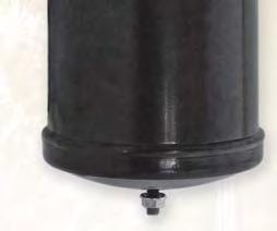
235 11 Receivers Liquid Horizontal & Vertical Receivers

.")
 -40 C up to +80 C Leak Testing: 100% bubble leak tested Paint: Powder paint giving protection to 500 hours salt spray")
236 RT Liquid horizontal and vertical receivers RT liquid receivers ensure storage of refrigerant in liquid phase for: - Variation of load demands of thermodynamic systems - Allows pump down regulation - Maintenance of equipments without recover refrigerant RT liquid receivers are made with steel tubes and end caps and are equipped with ODF, or Rotalock connections. Some models are delivered with a rotalock valve on the outlet connection. A very large range of models from 0.3 liter to 18 liters and all products with a tube diameter 152 mm are equipped with a fusible plug (221 C). The receiver volume must at minimum 25% larger than the total volume of refrigerant inside the circuit. Benefits Max Working Pressure Temperature Range 35 bar (500 psig) -40 C up to +80 C Leak Testing: 100% bubble leak tested Paint: Powder paint giving protection to 500 hours salt spray Approvals: PED 97/23/EC UL file no. SA / SA-5915 CSA LR41494 reserves the right to change this document without notice. For all requests, consult your nearest Wholesaler or contact us on: 236 RACE Catalogue R & A/C gal-1a/uk - Ed. November 2011
237 Technical Data Part Number Connections Size Rotalock Volume Dimensions (mm) Inlet (ODF) Outlet (liters) A B C D CE Category Weight (kg) RT-256V-TS 1/4" 1/4 ODF RT-306V-TS 1/4" 1/4 ODF RT-306V-TR 1/4" 3/4-16 UNF Connection RT-308V-TR 1/4" 3/4-16 UNF Connection RT-312V-TS 3/8" 3/8 ODF RT-3510V2S-KS 1/4" 1/4 ODF Valve RT-507V-TR 1/4" 3/4-16 UNF Connection I RT-510V3S-KS 3/8" 3/8 ODF Valve I RT-512V-TR 3/8" 3/4-16 UNF Connection I RT-612V-TR 3/8" 3/4-16 UNF Connection I RT-612V3S-KS 3/8" 3/8 ODF Valve I RT-615V-TR 3/8" 1"-14 UNF Connection II RT-616V3S-KS 3/8" 3/8 ODF Valve II RT-616V4S-MS 1/2" 1/2 ODF Valve II RT-618V4S-KS 1/2" 1/2 ODF Valve II RT-619V-TR 1/2" 1"-14 UNF Connection II 8 3 RT-623V4S-KS 1/2" 1/2 ODF Valve II RT-623V5S-MS 1/2" 5/8 ODF Valve II RT-510H-TS 1/2" 1/2 ODF I RT-536H-TS 1/2" 1/2 ODF II 12 5 RT-542H-TS 1/2" 1/2 ODF II 14 5 RT-618H-TS 1/2" 1/2 ODF II 9 5 RT-636H-TS 1/2" 1/2 ODF II 16 5 RT-642H-TS 1/2" 1/2 ODF II 20 5 Type 11 For all requests, consult your nearest Wholesaler or contact us on: 237 RACE Catalogue R & A/C gal-1a/uk - Ed. November 2011
238 Notes For all requests, consult your nearest Wholesaler or contact us on: 238 RACE Catalogue R & A/C gal-1a/uk - Ed. November 2011


239 12 Accumulators Suction Line Accumulators, Ensuring Protection of Compressors

240 VA, VPA, VCA Series Suction line accumulators Suction accumulators ensure protection of compressors in case of return of liquid refrigerant or lubricant trapped into the system. Suction accumulators work like a drop vapor separators and trap liquid refrigerant and oil at the bottom. They must be installed between evaporator outlet and compressor inlet. Vapors are sucked up by the compressors at the top, liquid refrigerant and oil are sucked at the bottom through a calibrated opening. The selection of suction accumulators needs to take in count the volume of liquid refrigerant and minimum capacity of the system to ensure a perfect oil return, be sure to add a volume of oil equivalent to the volume trapped and loose in the bottom, see below "Retention volume". Benefits Max Working Pressure Temperature Range 21 bar (300 psig) -40 C up to +80 C Leak Testing: 100% bubble leak tested Paint: Powder paint giving protection to 500 hours salt spray Approvals: PED 97/23/EC UL file no. SA-4835 / SA-5764e CSA LR41494 reserves the right to change this document without notice. For all requests, consult your nearest Wholesaler or contact us on: 240 RACE Catalogue R & A/C gal-1a/uk - Ed. November 2011
241 Technical Data VCA Series are dedicated to heat pumps and refrigeration systems with pump down. 12 VPA Series are suction accumulators with U tube Part Connections Internal Dimensions (mm) Weight CE Number volume volume Kg Category ODF Liters ml A B C E VCA-32-6S 3/4" VCA-33-7S 7/8" I VCA-45-7S 7/8" Part Connections Internal Dimensions (mm) Weight CE Number volume volume Kg Category ODF Liters ml A B C E VPA-589-6SRD 3/4" I VPA-589-7SRD 7/8" & 3 VPA SRD 3/4" I VPA SRD 7/8" I VPA SRD 7/8" I VPA SRD 7/8" I VPA SRD 7/8" I For all requests, consult your nearest Wholesaler or contact us on: RACE Catalogue R & A/C gal-1a/uk - Ed. November 2011


242 Technical Data VA Series are suction accumulators with U tube. Part Connections Internal Retention Dimensions mm Weight CE Number volume volume Kg Category ODF Liters ml A B C E VA-30-4S 1/2" & 3 VA-31-5S 5/8" & 3 VA-32-5S 5/8" & 3 VA-32-6S 3/4" & 3 VA-35-5S 5/8" & 3 VA-35-6S 3/4" & 3 VA-44-5SRD 5/8" & 3 VA-44-6SRD 3/4" & 3 VA-54-6SRD 3/4" I VA-54-7SRD 7/8" I VA-55-7SRD 7/8" I VA-56-6SRD 3/4" I VA-56-7SRD 7/8" I VA-57-7SRD 7/8" I VA-57-9SRD 1-1/8" I VA-59-9SRD 1-1/8" I VA-59-11SRD 1-3/8" I VA-610-7SRD 7/8" I VA-610-9SRD 1-1/8" I VA SRD 1-3/8" I VA SRD 1-3/8" I VA SRD 1-5/8" I For all requests, consult your nearest Wholesaler or contact us on: 242 RACE Catalogue R & A/C gal-1a/uk - Ed. November 2011


243 Chemicals, Lubricants, Acid Test Kit & Mastic 13 Wide range of lubricants, cleaners and acid test kits REACH compliant
244 For all requests, consult your nearest Wholesaler or contact us on: 244 RACE Catalogue R & A/C gal-1a/uk - Ed. November 2011
245 Index Chemicals, Lubricants, Acid Test Kit & Mastic Lubricants Alkyl benzene Vacuum Pump Oil Mineral Oil POE Oil Compatibility Cross Reference chart Approval List Pump Oil Acid Test Kits ETK POE Test Kit TKO Mineral, Alkyl Benzene Test Kit TA-1 POE Mineral, Alkyl Benzene Test Kit RTK Retrofi t for POE Test Kit Cleaners Alkaline & Acid Cleaners Multipurpose Cleaners Ice Machine Cleaner Leak Locators Sprayers Drain Pan Treatments Mastic Insulation Tape Insulation Cork Insulation Mastic Thermal Mastic reserves the right to change this document without notice. For all requests, consult your nearest Wholesaler or contact us on: 245 RACE Catalogue R & A/C gal-1a/uk - Ed. November 2011


246 Maintenance and fixing of your installation is a rigorous task which needs only the best. This requires a complete range of products capable to help you whenever and wherever necessary and this at the best price and efficiency possible. Environment friendly, safety and efficiency have leaded our approach of Field service. Parker Virginia range is: Reach compliant Environment friendly Updated on a regular basis to follow regulation changes Thought for adaptation to field needs For all requests, e s, consult your nearest Wholesaler ror r contact us on: racecustomerservice@parker.com service@parker. er. com / w.pa r.com/ race 246 RACE Catalogue R & A/C gal-1a/uk - Ed. November 2011
247 Lubricants / Oils Parker lubricant range provides you with a large range of lubricant: Alkyl benzene Mineral POE lubricant What s in it for you? Compressor manufacturer approved High quality standard Using high performance additives Reach compliant Alkyl Benzene Lubricants Parker Virginia alkyl benzene lubricants have been recommended by refrigerant producers and compressor manufacturers for use with the interim HCFC s and Ammonia refrigerants. 13 What s in it for you? AB150 AB200 AB300 are Ammonia compatible Copeland approved Viscosity Product Name Part Number Volume (Litre) 150 SUS (ISO 32) AB / / SUS (ISO 46) AB SUS (ISO 68) AB For all requests, consult your nearest Wholesaler or contact us on: 247 RACE Catalogue R & A/C gal-1a/uk - Ed. November 2011


248 Virginia Dual Purpose Vacuum Pump Oil Virginia dual purpose vacuum pump oil has been specially formulated to seal and lubricate vacuum pumps and act as well as a highly effective fl ushing agent. Virginia dual purpose vacuum pump oil with its unique combination of additives gives a greater lubrication, and leaves a fi lm which will protect pumps from rust and corrosion. These additives not only prevent, but actually remove sludge that may have formed before the use of Virginia vacuum pump oil. What s in it for you? Lower vapor pressure Powerful anti-sludge Prevents rust and corrosion Product Name Part Number Volume (Litre) L L Suniso Mineral Refrigeration Oils SUNISO is the premium lubricant for Refrigeration and A/C application for over 40 years, this due to the long trouble-free service records of systems that have used Suniso refrigeration Oils. What s in it for you? SUNISO 3GS-1G is Copeland approved Low floc point. Low Paraffin wax content minimises the potential for wax separation when used in low temperature applications Low pour point prevents oil from congealing in refrigerant lines Controlled viscosity. SUNISO maintains high film strength even when diluted with refrigerant, yet remains fluid under extreme low temperature operating conditions High dielectric strength allows the oil/refrigerant mixture to serve as an insulator between the motor windings and the body in a compressor. Viscosity Product Name Part Number Volume (Litre) 150 SUS (ISO 32) Suniso 3GS-1G/5G / / SUS (ISO 68) Suniso 4GS-1G/5G / / SUS (ISO 100) Suniso 5GS-1G/5G / / RACE Catalogue R & A/C gal-1/uk - Ed. November 2011
249 Emkarate RL POE Lubricants Emkarate RL refrigeration lubricants are designed to meet the requirements of compressor manufacturers and service engineers. What s in it for you? Emkarate RL lubricants are approved by most of compressor manufacturers. The product line features more than 30 products offered in varying viscosities between 5 cst to 220 cst and have been developed for use with a wide range of refrigerants. The Emkarate RL products ensure excellent refrigerant/lubricant solubility, optimum viscosity and lubrication performance across the extreme pressure-temperature ranges encountered in today s compressor systems. Size tank available: From 1 litre to 200 litres Emkarate compatibility: All CFC, HCFCs, HFCs, carbon dioxide (R744) and hydrocarbons (e,g R-290, R600a) refrigerants. The range offers CO2 compatible reference, so that select the right reference, please contact us Emkarate RL lubricants are not compatible with ammonia (R-717) 13 Elastomers compatibility: Generally acceptable: HNBR, NBR (Buna-N), NYLON-6.6, TEFLON Marginal: EPDM (EPR), NEOPRENE Generally unacceptable: Butyl rubber, Fluorocarbon Rubber (FPM) (Viton), Natural Rubber (NR) NBR/HNBR should exceed >36% nitrile content. Elastomer compounds supplied by different suppliers can yield different results. Individual testing of specifi c products is highly recommended. For all requests, consult your nearest Wholesaler or contact us on: 249 RACE Catalogue R & A/C gal-1a/uk - Ed. November 2011
250 Emkarate Polyol Ester Cross Reference Table Industry Viscosity Emkarate RL Lubricant SUS ISO Lubricant Atochem Planet Elf ACD22AW RL 22H Atochem Planet Elf ACD32AW RL 32H Atochem Planet Elf ACD46AW RL 46H Atochem Planet Elf ACD68AW RL 68H Atochem Planet Elf ACD100AW RL 100E BVA S RL 46H BVA S RL 68H BVA RL 32H BVA RL 46H BVA RL 68H BVA RL 100E BVA Contact us BVA RL 170H BVA RL 220Hplus Castrol Icematic SW 20C RL 22H Castrol Icematic SW RL 22H Castrol Icematic SW RL 22H Castrol Icematic SW RL 32H Castrol Icematic SW 32 C RL 32H Castrol Icematic SW RL 46H Castrol Icematic SW 68A RL 68HP Castrol Icematic SW RL 68HP Castrol Icematic SW 68C RL 68H Castrol Icematic E RL 68H/68HP Castrol Icematic SW RL 100E Castrol Icematic E RL 100E Castrol Icematic SW RL 220Hplus Castrol Icematic SW 220XL RL 220Hplus Carrier PP RL 22H Carrier PP RL 68H Carrier PP RL 22H Carrier PP RL 32H Carrier PP RL 68H Carrier PP RL 32H Carrier PP RL 68H Carrier PP RL 32H Carrier PP RL 68HP Carrier PP RL 100E Carrier PP RL 220Hplus Carrier PP RL 220XL PP23BZ RL 32H PP23BZ RL 68HP PP23BZ RL 220Hplus For all requests, consult your nearest Wholesaler or contact us on: 250 RACE Catalogue R & A/C gal-1a/uk - Ed. November 2011
251 Emkarate Polyol Ester Cross Reference Table Industry Viscosity Emkarate RL Lubricant SUS ISO Lubricant PP33BZ RL 32H PP23BZ RL 68H Copeland 22CC RL 323MAF Copeland 323MAF RL 323MAF Copeland RL 170H CPI Solest RL 22H CPI Solest 31HE RL 32H CPI Solest RL 32H CPI Solest LT RL 32H CPI Solest LT32NA RL 32H CPI Solest 46N RL 46H CPI Solest 46NA RL 46H CPI Solest RL 68H CPI Solest 68NA RL 68H CPI Solest Contact us CPI Solest RL 170H CPI Solest RL 220Hplus Emery 2927-A RL 32H Freol Alpha RL 68H Hatco EAL RL 22H Hatco EAL 22CC RL 323MAF Hatco EAL 22A RL 22H Hatco EAL RL 32H Hatco EAL 32BC RL 32HB Hatco EAL 32ST RL 32H Hatco EAL RL 46H Hatco EAL RL 68H Hatco EAL RL 100 Henry Pro-Eco RL 22H Henry Pro-Eco RL 32H Henry Pro-Eco RL 32H Henry Pro-Eco RL 46H Henry Pro-Eco RL 68H Henry Pro-Eco RL 100E Hitachi SR RL 220Hplus HULS Anderol RCF-E RL 22H HULS Anderol RCF-E RL 32H HULS Anderol RCF-E RL 46H HULS Anderol RCF-E RL 68H HULS Anderol RCF-E RL 100E Hydro Balance ISO RL 32H Hydro Balance ISO RL 46H Hydro Balance ISO RL 68H For all requests, consult your nearest Wholesaler or contact us on: RACE Catalogue R & A/C gal-1a/uk - Ed. November 2011
252 Emkarate Polyol Ester Cross Reference Table Industry Viscosity Emkarate RL Lubricant SUS ISO Lubricant Hydro Balance ISO RL 100E Hydro Balance ISO RL 220Hplus Lubrizol 2916S RL 68H Lubrizol Lubrikuhl ISO RL 68H Mobil Artic EAL 322R RL 32H Mobil Artic 22CC RL 323MAF Mobil Artic RL 22H Mobil Artic 22A Contact us Mobil Artic 22BC Contact us Mobil Artic RL 32H Mobil Artic 32BC RL 32HB Mobil Artic 32ST RL 32HB Mobil Artic 323MAF RL 323MAF Mobil Artic RL 46H Mobil Artic RL 68H Mobil Artic RL 100E Mobil Artic RL 220Hplus National NPE RL 22H National NPE RL 32H National NPE RL 46H National NPE RL 68H National NPE RL 100E National NPE RL 170H National NPE RL 220Hplus Reniso Ttriton SE Contact us Reniso Ttriton SE Contact us Reniso Ttriton SE RL 170H Reniso E RL 32H Reniso E RL 68H Reniso E RL 100E Reniso Ttriton SEZ RL 22H Reniso Ttriton SEZ RL 32H Reniso Ttriton SEZ Contact us Reniso Ttriton SEZ RL 170H Summit RPE RL 32H Summit RPE RL 46H Summit RPE RL 68H Summit RPE RL 100E Suniso SL RL 22H Suniso SL RL 32H Suniso SL RL 46H Suniso SL RL 68H Suniso SL RL 100E For all requests, consult your nearest Wholesaler or contact us on: 252 RACE Catalogue R & A/C gal-1a/uk - Ed. November 2011
253 Emkarate Polyol Ester Cross Reference Table Industry Viscosity Emkarate RL Lubricant SUS ISO Lubricant Texaco HFC RL 22H Texaco HFC RL 32H Texaco HFC RL 68H Texaco HFC RL 220Hplus Texaco HFC 32NA RL 32H Texaco HFC 68NA RL 68H Texaco HFC 100NA RL 100E HTexaco HFC 220NA RL 220Hplus Thermoking RL 32H Thermoking RL 32H Thermoking RL 323MAF Thermoking Contact us York Type K RL 32H York Type L RL 32H York Type J RL 46H York Type H RL 68H York Type P Contact us 13 For all requests, consult your nearest Wholesaler or contact us on: 253 RACE Catalogue R & A/C gal-1a/uk - Ed. November 2011
254 Emkarate Polyol Ester Approval List BITZER Equipment Manufacturer BLISSFIELD BOCK Compressor Type Model Reciprocating (M) Reciprocating (H) Screw Reciprocating (M) Reciprocating Reciprocating (H, M, L) Reciprocating (H, M) For all requests, consult your nearest Wholesaler or contact us on: Approved Emkarate RL Grade(s) RL 32H RL 68H RL 170H RL 32H RL 68H RL 46H RL 68H BOEING Service (Aerospace) RL 68H Reciprocating RL 22H Centrifugal (17DA, 17EA) RL 32H Centrifugal (17MPS, 17FA) RL 68H Centrifugal (17EX, 19EA, EB, FA, 19XL/XT) RL 68HP CARLYLE CARRIER TRANSICOLD Centrifugal (19EX, 19XR/XRT) RL 68HP Centrifugal (17EX, 17FA, with external gears) RL 68H Reciprocating (05G, 5K, 5F, 5H, 06D, O6E, 06CC) RL 68H Screw (05T, 06T) RL 100E Screw (23XL, 23XG, 30GX, 30HX) RL 220XL Reciprocating RL 68H CARRIER TOYO Centrifugal RL 68HP Screw (06NF, 06NH) RL 220Hplus CARRIER TRANSICOLD Scroll RL 32-3MAF COPELAND Reciprocating & Scroll RL 32-3MAF Screw RL 170H DORIN Reciprocating RL 22H, 32H, 46H & 68H DUNHAM BUSH Reciprocating(D-B Metic and D line) RL 32H & 68H Screw RL 100E & 170H FRIGOPOL Reciprocating (60-DLB-13 to 80-DLB-30) RL 32H GRASSO (GEA) Reciprocating RL 32H, 68H & 100E Screw RL 100E & 170H HARTFORD Reciprocating (M) RL 32H Reciprocating (H) RL 68H KOBELCO Screw RL 220Hplus LOCKHEED MARTIN Used to service Lockheed owned compressors RL 68H McQUAY (J&E Hall) Centrifugal RL 32H Screw RL 68H, 68HP, 100E, 220Hplus MYCOM Screw RL 100E Reciprocating 68H, 100E NSN 6850-P4314-H RL 32H NSN RL 32HB NSN RL 46H NATO MILITARY NSN NSN RL 46H NSN RL 68H NSN RL 68H NSN RL 68H 254 RACE Catalogue R & A/C gal-1a/uk - Ed. November 2011
255 Emkarate Polyol Ester Approval List Equipment Manufacturer Compressor Type Model Approved Emkarate RL Grade(s) PRESTCOLD Reciprocating RL 32-3MAF REFCOMP Reciprocating RL 32H & 68H ROLTEC Screw RL 68H.170H & 220Hplus ROTOCOLD Rotary RL 100E ROYCE Reciprocating RL 32H Reciprocating RL 32H, 46H, & 68H SABROE Screw RL 68H, 100E, 170H Screw RL 220Hplus THERMOKING Reciprocating RL 32H Reciprocating RL 68H TRANE Reciprocating Icematic AP32 Scroll RL 32HB Screw RL 68H Reciprocating Contact us YORK Centrifugal Contact us Screw Contact us 13 For all requests, consult your nearest Wholesaler or contact us on: 255 RACE Catalogue R & A/C gal-1a/uk - Ed. November 2011

 Both foot and hand format available Fully compatible with all lubricants Type Product Name Part Number Quantity Hand")
256 Oil Charging Pumps Parker offers 2 kinds of oil charging pumps which can accommodate most of containers. Both pumps are designed to pump against system pressure up to 17 bar (250 psi). VOP-H comes with an oil removal hose that is connected to the bottom of the pump. VOP-F is a higher volume pump designed to speed up jobs requiring larger amount of oil. The handy foot base increases the stability of the pump as larger amounts of oil are pumped. What s in it for you? Handy oil charging pump Capable to go again system pressure up to 17 bar (250 psi) Both foot and hand format available Fully compatible with all lubricants Type Product Name Part Number Quantity Hand style oil pump VOP-H Foot style oil pump VOP-F For all requests, consult your nearest Wholesaler or contact us on: 256 RACE Catalogue R & A/C gal-1a/uk - Ed. November 2011


257 Parker Virginia Acid Test Kit Range Parker provides you with a complete range of Oil test kit and retrofi t test kit, which is well known for its reliability and accuracy. This range is designed for detecting the presence and formation of acid in Air Conditioning and Refrigeration Systems. What s in it for you? Inexpensive and easy to use Every lubricant testable Reliable and accurate Parker Virginia - ETK Acid Test Kit To use with POE Oil 13 ETK test kit is a simple and cost effective method of determining whether the acid level is within an acceptable range for POE Lubricants. ETK acid test kit is adjusted for the higher acid levels of POE lubricants. What s in it for you? Inexpensive and easy to use Reliable and accurate One shot test, fast result Product Name Part Number Quantity ETK Uses: Simply fi ll the bottle with oil on bottle neck and shake. If test remains purple, the oil is safe: if it turns yellow, acid is too high. The ultra sensitive color change guarantees an accurate test. Marginal conditions cause partial color changes. A Color comparison chart is packed in every box. 257 RACE Catalogue R & A/C gal-1/uk - Ed. November 2011


258 Parker Virginia - TKO Acid Test Kit To use with Mineral and Alkyl Benzene Oil TKO acid test kit is similar to the ETK test kit, but formulated for Mineral or Alkyl benzene lubricants. TKO is a test for acid contamination in the compressor s crankcase which can be indicative of lubricant decomposition. What s in it for you? Inexpensive and easy to use Reliable and accurate One shot test, fast result Product Name Part Number Quantity TKO Uses: Simply fi ll the bottle with oil on bottle neck and shake. If TKO test remains purple, the oil is safe: if it turns yellow, acid is too high. The ultra sensitive color change guarantees an accurate test. Marginal conditions cause partial color changes. A Color comparison chart is packed in every box. Parker Virginia - TA-1 Multi-Lubricant Acid Test Kit To use with Mineral, Alkyl benzene and POE Oil TA-1 acid compact test kit offers you a simple way to test different kind of lubricant. TA-1 uses a simple scientifi c method capable to precisely measure the amount of acid in a lubricant sample taken from a contaminated system. The TA-1 has pre-measured solutions supplied in bottles with screw caps for easy handling. What s in it for you? Multi lubricant testable, Mineral, Alkyl benzene, POE Inexpensive and easy to use Acid content evaluation by range Reliable and accurate One shot test, fast result Product Name Part Number Quantity TA Uses: Indication for use on the back of each Tests pack! For all requests, consult your nearest Wholesaler or contact us on: 258 RACE Catalogue R & A/C gal-1a/uk - Ed. November 2011


259 Parker Virginia - RTK Retrofit Test Kit To use with POE Oil The RTK test kit is designed to analyse residual mineral oil content during retrofi t. The RTK retrofi t test kit gives you a simple but accurate indication of whether or not the mineral oil has been reduced to an acceptable level. What s in it for you? RTK test kit gives a visual indication if the mineral oil content is greater than 5%, between 1 and 5 % or below 1%. Easy and effective test Inexpensive to use Compact test kit Product Name Part Number Quantity RTK Uses: In preparation for retrofi tting a system from CFC/HCFC to an HFC refrigerant, the existing mineral oil must be fl ushed out, circuit must be cleaned with a parker WSL Burn out fi lter and the crankcase refi lled with a compatible lubricant. 13 For all requests, consult your nearest Wholesaler or contact us on: 259 RACE Catalogue R & A/C gal-1a/uk - Ed. November 2011


260 Parker Virginia Cleaners Range The Parker Virginia cleaner range is designed to make easier all your tasks even the most tedious. Our Cleaner range offers you solutions for outdoor and indoor cleaning jobs, this with acidic or alkaline product, to use straight or diluted. "Parker Virginia, your partner for efficient jobs." What s in it for you? Reach compliant Efficient and safe Regularly update of formulation to follow regulation change Biodegradable Acti Brite Foam Max Alki Foam Pro-Klean Acti-Klean Use Outdoor Outdoor Outdoor Outdoor Indoor PH Acidic Alkaline Alkaline Alkaline Alkaline Application: Condenser Coils Evaporator Coils + + Fan blades + Cleaning Power Oil & Grease Cooking Greases Corrosion & oxides Dirt & grime Dust & lint Bugs Grass & cottonwood Tobacco stains + Major Benefits Foaming "++" "+++" "++" Brightening "+++" + + Non-rinsing + Degreasing "++" "++" + Coil protection Bio-degradable RACE Catalogue R & A/C gal-1/uk - Ed. November 2011


261 Parker Virginia - Foam Max Parker Virginia Foam-Max is a high-foaming biodegradable, alkaline based, outdoor condenser coil cleaner designed for extra tough cleaning jobs. This cleaner creates thick foam when used on aluminum condenser coils that cuts through grease, grime, oil and pushes out feathers, dirt, dust, leaves and grass. What s in it for you? Condenser Cleaner High Foaming formulation Highly concentrated formulation Remove oxidation from the coil surface Degreasing action Product Name Part Number Volume (Litre) Quantity Foam Max Uses: His highly concentrated formula can be used in lighter dilution ratios to make an economical cleaner for standard cleaning jobs. PH: Alkaline / To use: Outdoor / Biodegradable. Parker Virginia - Alki Foam Parker Virginia Alki foam is an alternative method of cleaning fi n and tube surfaces of outdoor A/C and refrigeration condensers. The expanding foam action removes contamination from heat transfer surfaces which will optimise the airfl ow for sustainable performance of your installation. This biodegradable, high foaming formula cleaner is especially effective where grease accumulations have been deposited. Alki Foam also removes lint, grass, leaves, insects, feathers and smoke fi lm. 13 What s in it for you? Condenser cleaner Degreasing Action Foaming Formulation Remove oxidation Product Name Part Number Volume (Litre) Quantity Alki Foam Uses: Alki Foam is to use with any outdoor air conditioning, heat pump or refrigeration condenser coil which will require a deep cleaning to restore performance and system effi ciency. Applications Methods: Low pressure tank sprayers recommended. PH: Alkaline / To use: Outdoor / Biodegradable. For all requests, consult your nearest Wholesaler or contact us on: 261 RACE Catalogue R & A/C gal-1/uk - Ed. November 2011

262 Parker Virginia - Acti Klean Parker Virginia Acti Klean is a heavy duty combination of cleaners and surfactants in a concentrated evaporator coil cleaner. Acti Klean provides effective deep cleaning of evaporator coils to help restore system effi ciency. This cleaner is fast acting, biodegradable, nontoxic and easy to use. Periodic usage prevents odor caused by accumulations of dirt. Acti Klean cleans coils of dirt, lint, hair, grease, slime accumulations, and oil. Coil must be rinsed with potable water. What s in it for you? Evaporator cleaner Non rising formulation Biodegradable Product Name Part Number Volume (Litre) Quantity Acti Klean Uses: To use with any air conditioning, heat pump or refrigeration application which would benefi t from a deep cleaning of the evaporator coil to maintain or restore the maximum effi ciency possible. Also effective on electronic air cleaners and condenser coils which do not requires heavy cleaning, or where the use of more aggressive cleaners may be prohibitive. Applications Methods: High pressure sprayers Low pressure tank sprayers Soak, brush or sponge. Note: In order to take advantage of the self-rinsing nature of this product, the cooling system must be operational and capable of producing condensate. PH: Alkaline / To use: Indoor. Parker Virginia - Acti Brite Acti brite is an acid based outdoor condenser coil cleaner. It is designed to remove contamination from heat transfer surfaces and increase the airfl ow. Foam will wipe out stubborn deposits from air cooled condensers, leaving them clean and bright. The liquid penetrates deep into the recesses of the coils and the expanding foam will remove contamination such as lint, grass, leaves, insects, feathers and smoke fi lm so that it will be rinsed away easily with water. What s in it for you? Condenser cleaner Brightens Aluminum Foaming formulation Product Name Part Number Volume (Litre) Quantity Acti Brite Uses: Deep cleaning of outdoor condenser coils to restore effi ciency and increase performance of the system. Applications Methods: Low pressure, acid resistant tank sprayers are recommended. Regardless of application method, avoid inhalation of mist or contact of liquid or mist with skin. PH: Acidic / To use: Outdoor. 262 RACE Catalogue R & A/C gal-1/uk - Ed. November 2011
263 Parker Virginia - ProKlean MPC The special formulation of this biodegradable, multi-purpose cleaner provides effective removal of stubborn deposits which may have proven resistance to other cleaners. Proklean MPC is ideal for diffi cult cleaning tasks such as cleaning electronic air cleaners, permanent air fi lters, evaporator and condenser coils, and other applications which require deep penetrating action. ProKlean MPC is fully compatible with use of high pressure washers. What s in it for you? Evaporator and condenser cleaner Fan blades cleaner Electronic air filter cleaner Product Name Part Number Volume (Litre) Quantity Proklean MPC Uses: Any application requiring either a light or deep cleaning from dirt, dust, grease, oil or virtually any other substance encountered in the HVAC industry. Such applications include condensers, evaporators, electronic air cleaners. Applications Methods: Low pressure, tank sprayers are recommended for strong dilutions By hand with protective gloves with weaker dilutions. PH: Alkaline / To use: Outdoor / Biodegradable. Parker Virginia - Metal Safe Ice Machine Cleaner Metal Safe Ice machine is used to clean all types of ice machines as cube, tube or flake, and for descaling commercial dishwashers. It will restore ice machine effi ciency and taste by removing the lime scale build up that develops on ice machines. Metal safe ice machine cleaner is safe to use on nickel and tin plated evaporators. 13 What s in it for you? Leaves no after taste Leaves no odor Product Name Part Number Volume (Litre) Quantity H H Uses: To use with any standard ice machine, steam table or commercial dishwasher application which requires the removal of scale to help restore effi ciency? Applications Methods: Circulation pump Brush on hard to clean parts. 263 RACE Catalogue R & A/C gal-1/uk - Ed. November 2011

 Quantity GL6 475053 0.")
264 Parker Virginia - Gas Leak Locator This leak detector is a high viscosity formula, allowing it to be used on higher temperature applications. A stream of bubbles will form in a few seconds if a leak is present. What s in it for you? High viscosity formula for higher temperature applications Non-freezing formulation makes it also effective on all low temperature applications. Fluorescent dye for high visibility Ticks to fittings and joints Brush include Product Name Part Number Volume (Litre) Quantity GL Uses: Any air conditioning, heat pump or refrigeration system in which leaks are possible, either from an installation, or where loss of the refrigerant charge indicates a leak is present. Applications Methods: Gas Leak Locator may be applied by brushing the liquid on fi ttings and joints with the supplied brush. Parker Virginia - Locator Leak Detector "No bubbles, No leak" An extremely effective leak locator contained in an easy to use package. Due to its unique formulation, this leak detector is more accurate than electronic leak detectors and can even detect microscopic system leaks within seconds. Simply spray it on connections and look for the bubbles. Locator has been formulated with a red fluorescent dye making visibility easier, even in low light. As it comes in a handy spray bottle, it is ideal for checking leaks in hard to reach areas, such as inside coils and on fittings that are not easy to reach. What s in it for you? Design to search leakage on hard reach area Fluorescent dye for high visibility Product Name Part Number Volume (Litre) Quantity LOC-LEAK LOCATOR For all requests, consult your nearest Wholesaler or contact us on: 264 RACE Catalogue R & A/C gal-1a/uk - Ed. November 2011
 Quantity Spray Pump 475191 3.")


265 Parker Virginia - Sprayer This is Sprayer is economical and 100% polyethylene made of. The sturdy tank, pump, nozzle and wand make spraying clean and easy. Translucent tanks make it easy to check the chemical level. Product Name Part Number Volume (Litre) Quantity Spray Pump Parker Virginia - CDC Anticlog Drain Pan Treatments CDC anti-clog is a simple to use highly effective biocide. This condensate drain pan treatment controls the growth of algae, slime and inhibits the growth of harmful bacteria, including those causing Legionnaires disease. Unlike tablets, the plastic encapsulated unit will not block the condensate drain. A corrosion inhibitor is also released to provide rust protection to all metal parts exposed to the condensate. Depending on the climate and the amount of condensate produced, CDC anti-clog will provide effective treatment of condensate for up to 4 months of protection. 13 What s in it for you? Effective against Legionella. Reduces odors by eliminating slime bacteria waste. Long lasting, Effective treatment of condensate for up to 4 months Easy to install. Keeps drain pans clear, preventing pan overflows. Allows for placement either in pan or on the side of the coil. Inhibits corrosion in drain pans. Product Name Part Number Capacity (kw) Weight (kg) Quantity ANTICLOG AT/C ANTICLOG FT/C Up to For all requests, consult your nearest Wholesaler or contact us on: 265 RACE Catalogue R & A/C gal-1a/uk - Ed. November 2011


 Polyethylene Uses: Foam insulation tape is to be used where pipes or tubing need to be insulated to prevent heat transfer or condensate drip.")
266 Parker Virginia Foam Insulation Tape Insulation tape will prevent pipe to sweat. Foam insulation tape can also be used to reduce heat loss on hot pipes below 71 C. The Tape Easily cuts into pieces and molds around fi ttings and valves, eliminating the high costs of specialty cast forms. Foam insulation tape adheres to clean metal and to itself. Virginia Cork Insulation Tape is similar to the Presstite brand and is a lower cost alternative to the premium brand. What s in it for you? Prevents condensation drip from forming on pipes and tubing Easy to cut in piece for molding around hard to wrap fitting Product Name Part Number Quantity Size - Type K (0.3 cm x 7.5cm x 9m) K (0.3 cm x 7.5 cm x 9 m) Polyethylene Uses: Foam insulation tape is to be used where pipes or tubing need to be insulated to prevent heat transfer or condensate drip. Applications Methods: Adhering surfaces should be clean and dry Wrap the tape in a spiral around the tubing, butting the edges together so that no tubing is showing through. Note: Do not stretch. To cover valves and fi ttings, cut the tape into smaller pieces and apply. Subsequent wrappings can be made as required. Reverse the direction of wrap with each subsequent wrapping. For all requests, consult your nearest Wholesaler or contact us on: 266 RACE Catalogue R & A/C gal-1a/uk - Ed. November 2011

267 Presstite & Virginia Cork Insulation Tape Presstite is the premium product of its type. It may be used for either hot or cold temperature applications within its continuous duty service temperature range of -29 C to 93 C. Presstite is designed to be use on pipes or tubes, in commercial or residential buildings, A/C units, refrigerated units and other similar types of applications. Presstite will stop dripping caused by pipe condensation, will adhere to metal and will not crack or dry out. Presstite is self an adhering tape. What s in it for you? High quality formulation to better stick to pipes and fitting Prevents condensation drip from forming on pipes and tubing Easy to cut in piece for molding around hard to wrap fitting Product Name Part Number Quantity Size - Type PT (0.3 cm x 7.5cm x 9m) VCT Bulk (0.3 cm x 7.5cm x 9m) Uses: To use with any application in which piping or tubing need to be insulated to prevent heat transfer or condensate formation and drip. Applications Methods: Adhering surfaces should be clean and dry Wrap the tape in a spiral around the tubing, butting the edges together with your fi ngers as you go. Note: Do not stretch. Do not overlap edges. Subsequent wrappings can be made as required. Reverse the direction of wrap with each subsequent wrapping. 13 For all requests, consult your nearest Wholesaler or contact us on: 267 RACE Catalogue R & A/C gal-1a/uk - Ed. November 2011

 is one of the most diffi cult industrial sealing problems that can be solved with these")

 PP36 475301 12 Cords (0.95 cm x 7.")
268 Parker Virginia Presstite Permagum Sealing Gum These sealing gums are a non-hardening, water-resistant, formulated from the highest quality materials. They are non-staining, non-bleeding, and have excellent adhesion, they are supplied in ready-to-use extruded beads or bulk slugs. Presstite Pergamum is specifi cally designed to exclude dirt, dust and moisture from joints. Constant exposure to extreme conditions (like those encountered by trailers) is one of the most diffi cult industrial sealing problems that can be solved with these sealing gums. Also excellent for use in sealing around window units and refrigerated cases. What s in it for you? Seals out moisture, dust and dirt. Resistant to water, water vapor, temperature, alcohol, and mild acids or caustics. Service temperature range from -34 C to70 C. Excellent adhesion to wood, metal, plastics, glass, as well as many other surfaces. On-staining, non-drying Product Name Part Number Quantity Size - Type - Weight PP Cords (0.4 cm x 30 m) PP Cords (0.95 cm x 7.5 m) PP Slugs 1 kg Applications Methods: Adhering surfaces should be clean and dry Place Permagum over opening to be sealed and gently press into place with thumbs. For all requests, consult your nearest Wholesaler or contact us on: 268 RACE Catalogue R & A/C gal-1a/uk - Ed. November 2011


269 ParkerVirginia Insulation Mastic Parker Virginia insulation mastic is asphalt emulsion containing a highly effi cient cellular material for reducing heat transfer and conductivity. It is designed specifi cally for coating large area surfaces to prevent moisture condensation and dripping. Once dry, insulation mastic is waterproof and will form a coating that is resistant to strong acids and alkaline. Parker Virginia insulation mastic is an excellent weather proofer. It is non-poisonous, non-corrosive and odorless. Virginia Insulation Mastic has a temperature range -29 C to 93 C, and will not fl ow below 121 C. What s in it for you? Reduces heat transfer and conductivity. Forms a coating that is resistant to strong acids and alkalines. Dries non-toxic, non-poisonous, odorless and waterproof. Product name Part Number Volume (Litre) Quantity PM Applications Methods: Can be brushed on using a stiff bristle brush (such as a whiskbroom). Can be troweled on in the same manner as wall plaster. 13 For all requests, consult your nearest Wholesaler or contact us on: 269 RACE Catalogue R & A/C gal-1a/uk - Ed. November 2011

270 Parker Virginia Thermal Mastic Heat Conducter Parker Virginia thermal mastic is heat conducting compound that increases heat transfer four times the amount of mechanical mounting alone. The result is a faster response times for expansion valves and controls when connecting the sensor bulb to the suction line, better heat transmission between coils and liners. Parker Virginia thermal mastic has a working temperature range from -76 C to 100 C. What s in it for you? Stable between -76 C to 100 C. Increases heat transfer between surfaces 4 times over mechanical mounting alone. Replaces solder for heat transmission. Product Name Part Number Volume (Litre) Quantity PM PM PM PM Applications Methods: Can be applied by squeezing tube or by troweling in bulk quantities. Protective gloves should be worn. For all requests, consult your nearest Wholesaler or contact us on: 270 RACE Catalogue R & A/C gal-1a/uk - Ed. November 2011


271 Parker Virginia Thermal Block Heat Discharger Parker Virginia thermal Block effectively absorbs surface heat generated by welding, brazing or soldering. Heat can transmit along pipes and other surfaces and damage sensitive materials and painted surfaces. Thermal Block helps prevent warping, buckling or other distortion on light gauge material, as well as preventing blistering, discoloration or cracking. Now there is no longer any need for wet rags and ice blocks. Thermal Block is applied directly out of the tube onto the surface that needs protection (expansion valve, fi lter drier, sight glass and ball valve). Parker Virginia Thermal Block is easily cleaned up with water and can be applied to all metals. What s in it for you? Effectively absorbs heat from welding, brazing or soldering. Can prevent warping, buckling or other distortion of light gauge material. Can prevent discoloration, blistering or cracking. Water soluble. Non toxic, harmless to skin, odourless and asbestos free. Adheres to surface for horizontal, vertical or overhead application. Can be applied to all metals. Product Name Part Number Volume (Litre) Quantity TB Applications Methods: Apply directly out of tube in thick bead on any clean dry surface. For all requests, consult your nearest Wholesaler or contact us on: 271 RACE Catalogue R & A/C gal-1a/uk - Ed. November 2011
272 Notes For all requests, consult your nearest Wholesaler or contact us on: 272 RACE Catalogue R & A/C gal-1a/uk - Ed. November 2011


273 ACR & Refrigeration 14 Copper Fitting Range for HVAC Application


274 Refrigeration, Air conditioning, Heat Pump Copper tube is widely used in air conditioning and refrigeration systems because of its high thermal conductivity which is about 8 times more than aluminum tube. Copper has gained new popularity in its modern form: Light, Strong, Corrosion-resistance fittings. Its long lasting and maintenance free characteristics make copper the leading choice for heating, cooling and other mechanical systems. Parker offers an excellent quality of copper fittings which provide an economic and efficient method of piping. Manufactured to meet or exceed European and international standard. Made from premium quality copper. Copper fittings require a high level of reliability, and cleanliness, our range totally comply with the highest standard in the HVAC world. High reliability product. Comply with ASME B16.22 and EN378. Compatible for use with all CFC, HFC, HCFC. For all requests, consult your nearest Wholesaler or contact us on: 274 RACE Catalogue R & A/C gal-1a/uk - Ed. November 2011
275 Index Copper fittings 100-RS Series - Coupling with Stop C x C Series - Coupling with Roll Stop C x C Series - Coupling without Stop C x C R Series - Reducer Coupling with C x C Series - Fitting Reducer FTG x C Series - Female Adaptor C x F Series - Male Adaptor C x M Series - Male Street Adaptor FTG x M C Series - 90 Elbows Close Ruff C x C CR Series - 90 Elbows Reducer Close Ruff C x C C-2 Series - 90 Elbows Street Close Ruff FTG x C C Series - 90 Elbows Street Close Ruff FTG x FTG MT Series - 90 Elbows Medium Turn C x C MT-2 Series - 90 Elbows Medium Turn FTG x C L Series - 90 Elbows Long Turn C x C R Series - 90 Elbows Reducer C x C L-2-90 Elbows Street Long Turn FTG x C L Series - 90 Elbows Street Long Turn FTG x FTG Series - 45 Elbows C x C Series - 45 Elbows FTG x C Series - Tee Trap C x C x C Series - Tee Trap C x C Series - Return Bend C x C Series - Fitting End Plug Series - Tube Cap reserves the right to change this document without notice. For all requests, consult your nearest Wholesaler or contact us on: 275 RACE Catalogue R & A/C gal-1a/uk - Ed. November 2011
276 HVAC Market Description of Applications We offer a wide variety of copper fittings that are are used in both a domestic and commercial applications of air conditioning, refrigeration and heating. Functions Description KEY - Symbol of joint ends C Solder joint fi tting end made to receive copper tube diameter. FTG Solder joint fi tting end made to copper tube diameter. F M Internal ANSI Standard Taper Pipe Thread-Female. External ANSI Standard Taper Pipe Thread-Male. 100 Series - Coupling with stop C x C Coupling with stop C x C Figure Ref Parker P/N O. D. Size inch Box Quantity Dim. A Dim. B Dim. C Weight (kg) * /8" 50 3/32" /8" 100 3/32" /4" 25 3/32" /8" 50 3/32" " 1/8 25 3/32" " 3/8 20 3/32" " 5/8 10 3/32" " 1/8 5 3/32" " 5/8 5 3/32" " 1/8 5 3/32" " 5/8 1 3/32" For all requests, consult your nearest Wholesaler or contact us on: * The indication of weight is approximate. 276 RACE Catalogue R & A/C gal-1a/uk - Ed. November 2011
277 100-RS Series - Coupling with roll stop C x C Coupling with roll stop C x C Figure Ref Parker P/N O.D. Size inch Box Quantity Dim. A Dim. B Dim. C Weight (kg) * 100-RS /16" 50 1/16" RS /4" 50 1/16" RS /16" 50 1/16" RS /8" 50 3/32" RS /2" 50 3/32" RS /8" 100 3/32" RS /4" 25 3/32" RS /8" 50 3/32" RS " 10 3/32" RS " 1/8 25 3/32" RS " 3/8 20 3/32" RS " 5/8 10 3/32" RS " 1/8 5 3/32" * The indication of weight is approximate. 101 Series - Coupling without stop C x C Coupling without stop C x C Figure Ref Parker P/N O. D. Size inch Box Quantity For all requests, consult your nearest Wholesaler or contact us on: Dim. A Dim. B Dim. C Weight (kg) * /4" 50 11/16" /8" 50 23/32" /2" 50 55/64" /8" 100 1" 3/ /4" 25 1" 21/ /8" 50 1" 19/ " 1/8 25 1" 29/ " 3/8 20 2" 1/ " 5/8 10 2" 17/ " 1/8 5 2" 49/ " 5/8 5 3" 1/ " 1/8 5 3" 13/ " 5/8 1 3" 29/ * The indication of weight is approximate RACE Catalogue R & A/C gal-1a/uk - Ed. November 2011
278 101-R Series - Reducer coupling with stop C x C Reducer coupling with stop C x C Figure Ref Parker P/N O. D. Size inch Box Quantity For all requests, consult your nearest Wholesaler or contact us on: Dim. A Dim. B Dim. C Weight (kg) * 101-R /8" x 1/4" 50 5/32" R /8" x 5/16" 50 3/32" R /16" x 1/4" 50 3/32" R /2" x 3/8" 50 3/16" R /2" x 1/4" 50 1/4" R /8" x 1/2" 50 5/32" R /8" x 3/8" 50 1/4" R /8" x 1/4" 50 5/32" R /4" x 5/8" 25 5/32" R /4" x 1/2" 25 7/32" R /4" x 3/8" 25 5/16" R /8" x 3/4" 50 3/16" R /8" x 5/8" 50 3/16" R /8" x 1/2" 50 21/64" R /8" x 3/8" 50 7/16" R " 1/8 x 7/8" 25 13/32" R " 1/8 x 3/4" 25 3/8" R " 1/8 x 5/8" 25 7/16" R " 1/8 x 1/2" 25 1/2" R " 3/8 x 1" 1/8 10 5/16" R " 3/8 x 7/8" 10 15/32" R " 3/8 x 5/ /64" R " 5/8 x 1 3/ /32" R " 5/8 x 1/1/8 10 7/16" R " 5/8 x 7/8" 10 21/32" R " 5/8 x 5/ /32" R " 1/8 x 1 5/ /32" R " 1/8 x 1 3/ /32" R " 1/8 x 1" 1/ /32" R " 1/8 x 7/8" 10 1" R " 1/8 x 5/8 10 1" 1/ R " 5/8 x 2" 1/8 5 15/32" R " 5/8 x 1 5/8 5 7/8" R " 5/8 x 1 3/8 5 15/16" R " 5/8 x 1" 1/8 5 1" 1/ R /8 x 2 5/8 2 1/2" R /8 x 2" 1/8 2 13/16" R /8 x 1 5/8 2 1" 5/ R /8" x 3 1/8 1 1/2" * The indication of weight is approximate. 278 RACE Catalogue R & A/C gal-1a/uk - Ed. November 2011
279 118 Series - Fitting reducer FTG x C Fitting reducer FTG x C Figure Ref Parker P/N O. D. Size inch Box Quantity For all requests, consult your nearest Wholesaler or contact us on: Dim. A Dim. B Dim. C Weight (kg) * /4" x 1/8" 50 33/64" /8" x 1/4" 50 1/2" /2" x 3/8" 50 17/32" /2" x 1/4" 50 5/8" /8" x 1/2" 50 23/32" /8" x 3/8" 50 47/64" /4" x 5/8" 25 25/32" /4" x 1/2" 25 29/32" /4" x 3/8" 25 15/16" /8" x 3/4" 50 15/16" /8" x 5/8" 50 1" /8" x 1/2" 50 1" 1/ /8" x 3/8" 50 1" 1/ " 1/8 x 7/8" 25 1" 3/ " 1/8 x 3/4" 25 1" 7/ " 1/8 x 5/8 25 1" 15/ " 1/8 x 1/2" 25 1" 3/ " 3/8 x 1" 1/8 10 1" 1/ " 3/8 x 7/8" 10 1" 11/ " 3/8 x 5/8" 10 1" 15/ " 5/8 x 1" 3/8 10 1" 19/ " 5/8 x 1" 1/8 10 1" 17/ " 5/8 x 7/8" 10 1" 11/ " 5/8 x 5/8" 10 1" 7/ " 1/8 x 1"5/8 10 1" 11/ " 1/8 x 1" 3/8 10 1" 15/ " 1/8 x 1" 1/8 10 2" 1/ " 1/8 x 7/8" 10 2" 11/ " 1/8 x 5/8" 10 2" 7/ " 5/8 x 2" 1/8 5 1" 15/ " 5/8 x 1" 5/8 5 2" 1/ " 5/8 x 1" 3/8 5 2" 5/ " 5/8 x 1" 1/8 5 2" 17/ " 1/8 x 2" 5/8 2 2" 3/ " 1/8 x 2" 1/8 2 2" 33/ " 1/8 x 1" 5/8 2 2" 11/ " 1/8 x 1" 3/8 2 2" 25/ " 5/8 x 3" 1/8 1 2" 1/ " 5/8 x 2" 5/8 1 2" 7/ " 5/8 x 2" 1/8 1 2" 51/ * The indication of weight is approximate RACE Catalogue R & A/C gal-1a/uk - Ed. November 2011
280 103 Series - Female adaptor C x F Female adaptor C x F - NPT Thread Figure Ref Parker P/N Series - Female adaptor FTG X F O. D. Size Inch x NPT Thread Box Quantity Dim. A Dim. B Dim. C Weight (kg) * /4" x 1/4" 50 1/2" /8" x 1/4" 50 15/32" /8" x 1/2" 50 25/32" /8" x 3/8" 50 15/32" /8" x 1/8" 50 11/32" /2" x 3/8" 50 15/32" /2" x 3/4" 25 3/4" /2" x 1/2" 50 7/8" /2" x 1/4" 50 15/32" /8" x 1/2" 50 7/8" /8" x 3/4" 25 29/32" /8" x 3/8" 50 9/16" /8" x 1/4" 50 15/32" /4" x 3/4" 25 1" /4" x 1/2" 25 3/4" /8" x 3/4" 25 23/32" /8" x 1" 20 1"7/ /8" x 1/2" 25 19/32" "1/8 x 1" 20 31/32" "1/8 x 1"1/4 10 1"7/ "1/8 x 3/4" 25 43/64" "1/8 x 1/2" 10 11/16" "3/8 x 1"1/4 10 1"3/ "3/8 x 1"1/2 10 1"19/ "3/8 x 1" 10 55/64" "5/8 x 1"1/2 10 1"5/ "5/8 x 2" 5 1"7/ "1/8 x 2" 5 1"1/ "5/8 x 2"1/2 2 1"1/ * The indication of weight is approximate. Female adaptor FTG X F - NPT Thread Figure Ref Parker P/N O. D. Size Inch x NPT Thread Box Quantity For all requests, consult your nearest Wholesaler or contact us on: Dim. A Dim. B Dim. C Weight (kg) * /8 X 1/ / /2 X 3/ / /8 X 1/ / /8 X 3/ / /8 X / /8 X 1 1/ / /8 X 1 1/ / /8 X / * The indication of weight is approximate. 280 RACE Catalogue R & A/C gal-1a/uk - Ed. November 2011
 * 104 10020036 1/4\" x 1/8\" 50 13/32\" - - 0.019 104 10020037 1/4\" x 3/8\" 50 3/4\" - - 0.043 104 10020038 1/4\" x 1/4\" 50 7/16\" - - 0.")
281 104 Series - Male adaptor C x M Male adaptor C x M - NPT Thread Figure Ref Parker P/N O. D. Size Inch x NPT Thread Box Quantity For all requests, consult your nearest Wholesaler or contact us on: Dim. A Dim. B Dim. C Weight (kg) * /4" x 1/8" 50 13/32" /4" x 3/8" 50 3/4" /4" x 1/4" 50 7/16" /8" x 1/4" 50 15/32" /8" x 1/2" 50 7/8" /8" x 3/8" 50 63/64" /8" x 1/8" 50 17/32" /2" x 3/8" 50 7/8" /2" x 3/4" /32" /2" x 1/2" 50 15/16" /2" x 1/4" 50 5/8" /8" x 1/2" 50 19/32" /8" x 1" 20 19/32" /8" x 3/4" 25 13/16" /8" x 3/8" 50 3/4" /8" x 1/4" 50 5/8" /4" x 3/4" 25 1"1/ /4" x 1/2" 25 11/16" /8" x 3/4" 25 13/16" /8" x 1" 20 1"31/ /8" x 1/2" 25 59/64" "1/8 x 1" 20 27/32" "1/8 x 1"1/2 10 1"29/ "1/8 x 1"1/4 10 1"21/ "1/8 x 3/4" 25 1"3/ "1/8 x 1/2" 25 29/32" "3/8 x 1"1/ /16" "3/8 x 1"1/2 10 1"45/ "3/8 x 1" 10 1"1/ "3/8 x 3/4" 10 1" "5/8 x 2" 5 1"25/ "5/8 x 1"1/4 10 1"27/ "5/8 x 1"1/2 10 7/8" "5/8 x 1" 10 1"15/ "1/8 x 2" 5 31/32" "1/8 x 1"1/4 5 1"3/ "5/8 x 2"1/2 4 1"7/ "1/8 x 3" 2 1"25/ * The indication of weight is approximate RACE Catalogue R & A/C gal-1a/uk - Ed. November 2011
 * 104-2 10020075 3/8\" x 1/4\" 50 1\"1/16 - - 0.033 104-2 10020076 1/2\" x 3/8\" 50 1\"3/16 - - 0.049 104-2 10020077 5/8\" x 1/2\" 50 1\"7/16 - - 0.")


 * 107-CR 10020664 5/8\" x 3/8\" 50 11/16\" 43/64\" - 0.")
282 104-2 Series - Male street adaptor FTG x M Male street adpator FTG x M - NPT Thread Figure Ref Parker P/N O. D. Size Inch x NPT Thread Box Quantity Dim. A Dim. B Dim. C Weight (kg) * /8" x 1/4" 50 1"1/ /2" x 3/8" 50 1"3/ /8" x 1/2" 50 1"7/ /8" x 3/4" 25 1"27/ "1/8 X 1" 20 2"5/ "3/8 X 1"1/4 10 2"1/ "5/8 X 1"1/2 10 2"13/ "1/8 X 2" 5 2"13/ C Series - 90 Elbow close ruff C x C * The indication of weight is approximate. 90 Elbow Close ruff C x C Figure Ref Parker P/N O. D. Size inch Box Quantity Dim. A Dim. B Dim. C Weight (kg) * 107-C /4" 50 1/4" 1/4" C /8" 50 3/8" 3/8" C /2" 50 21/64" 21/64" C /8" /64" 23/64" C /4" 25 17/32" 17/32" C /8" 50 9/16" 9/16" C "1/ /64" 47/64" C "3/ /16" 15/16" C "5/8 20 1"11/64 1"11/ C "1/8 10 1"29/64 1"29/ C "5/8 5 1"21/32 1"21/ C "1/8 3 1"61/64 1"61/ C "5/8 1 2"7/32 2"7/ C "1/8 1 2"17/32 2"17/ CR Series - 90 Elbow reducer close ruff C x C * The indication of weight is approximate. 90 Elbow reducer close ruff C x C Figure Ref Parker P/N O. D. Size inch Box Quantity For all requests, consult your nearest Wholesaler or contact us on: Dim. A Dim. B Dim. C Weight (kg) * 107-CR /8" x 3/8" 50 11/16" 43/64" CR /8" x 1/2" 50 43/64" 5/8" CR /4" x 5/8" 25 31/32" 7/8" CR /8" x 5/8" 50 5/8" 15/32" CR "1/8 X 7/8" 25 3/4" 19/32" CR "1/8 X 5/8" 25 1"1/8 7/8" CR "3/8 X 1"1/8 10 7/8" 11/16" CR "5/8 X 1"3/8 10 1"9/64 55/64" CR "1/8 X 1"5/8 5 1"1/2 1"13/ CR "5/8 X 2"1/8 5 1"1/2 1"7/ CR "1/8 X 2"5/8 3 2"3/32 1"3/ * The indication of weight is approximate. 282 RACE Catalogue R & A/C gal-1a/uk - Ed. November 2011
 * 107-C-2 10020231 1/4\" 50 1/4\" 5/8\" - 0.006 107-C-2 10020232 3/8\" 50 3/8\" 3/4\" - 0.012 107-C-2 10020233 1/2\" 50 21/64\" 49/64\" - 0.")

 * 105-C 10020245 3/8\" 25 27/32\" - - 0.013 105-C 10020246 1/2\" 25 13/16\" - - 0.029 105-C 10020247 5/8\" 25 1\"1/32 - - 0.")
 * 107-MT 10020631 1/4\" 50 3/8\" 3/8\" - 0.010 107-MT 10020633 1/2\" 50 1/2\" 1/2\" - 0.043 107-MT 10020602 1\"1/8 10 47/64\" 47/64\" - 0.")
 * 107-MT-2 10020635 5/8\" 50 19/32\" 1\"3/16-0.066 107-MT-2 10020636 3/4\" 25 7/8\" 1\"1/2-0.104 107-MT-2 10020637 7/8\" 25 13/16\" 1\"5/8-0.146 107-MT-2 10020638 1\"1/8 10 1\"1/16 2\"1/32-0.")
283 107-C-2 Series - 90 Elbow street close ruff FTG x C 105-C Series - 90 Elbow street close ruff FTG x FTG 107-MT Series - 90 Elbow medium turn C x C 90 Elbow street close ruff FTG x C Figure Ref Parker P/N O. D. Size inch Box Quantity Dim. A Dim. B Dim. C Weight (kg) * 107-C /4" 50 1/4" 5/8" C /8" 50 3/8" 3/4" C /2" 50 21/64" 49/64" C /8" /64" 1"1/ C /4" 25 17/32" 1"7/ C /8" 50 19/32" 1"13/ C "1/ /32" 1"21/ C "3/8 25 7/8" 1"29/ C "5/8 20 1"11/64 2"3/ C "1/8 10 1"29/64 2"27/ C "5/8 5 1"3/4 3"21/ C "1/8 3 2" 3"25/ C "5/8 1 2"15/64 4"15/ * The indication of weight is approximate. 90 Elbow street close ruff FTG x FTG Figure Ref Parker P/N O. D. Size inch Box Quantity Dim. A Dim. B Dim. C Weight (kg) * 105-C /8" 25 27/32" C /2" 25 13/16" C /8" 25 1"1/ C /8" 25 1"13/ C "1/8 10 1"21/ * The indication of weight is approximate. 90 Elbow medium turn C x C Figure Ref Parker P/N O. D. Size inch Box Quantity Dim. A Dim. B Dim. C Weight (kg) * 107-MT /4" 50 3/8" 3/8" MT /2" 50 1/2" 1/2" MT "1/ /64" 47/64" * The indication of weight is approximate MT-2 Series - 90 Elbow medium turn FTG x C 90 Elbow medium turn FTG x C Figure Ref Parker P/N O. D. Size inch Box quantity Dim. A Dim. B Dim. C Weight (kg) * 107-MT /8" 50 19/32" 1"3/ MT /4" 25 7/8" 1"1/ MT /8" 25 13/16" 1"5/ MT "1/8 10 1"1/16 2"1/ For all requests, consult your nearest Wholesaler or contact us on: * The indication of weight is approximate. 283 RACE Catalogue R & A/C gal-1a/uk - Ed. November 2011
 * 107-L 10020248 3/16\" 50 5/16\" 5/16\" - 0.007 107-L 10020249 1/4\" 50 1/2\" 1/2\" - 0.008 107-L 10020250 5/16\" 50 9/16\" 9/16\" - 0.013 107-L 10020251 3/8\" 50 3/4\" 3/4\" - 0.")


284 107-L Series - 90 Elbow long - Long turn C x C 90 Elbow long, Long turn C x C Figure Ref Parker P/N O. D. Size inch Box Quantity Dim. A Dim. B Dim. C Weight (kg) * 107-L /16" 50 5/16" 5/16" L /4" 50 1/2" 1/2" L /16" 50 9/16" 9/16" L /8" 50 3/4" 3/4" L /2" 50 3/4" 3/4" L /8" 50 55/64" 55/64" L /4" 25 1"1/8 1"1/ L /8" 25 1"5/32 1"5/ L " 10 1"15/32 1"15/ L "1/8 10 1"29/64 1"29/ L "3/8 10 1"7/8 1"7/ L "5/8 10 2"3/16 2"3/ L "1/8 5 3" 3" L "5/8 1 3"3/16 3"3/ L "1/8 1 4"5/8 4"5/ L "5/8 1 5"1/4 5"1/ L "1/8 1 5"7/8 5"7/ R Series - 90 Elbow reducer C x C * The indication of weight is approximate. 90 Elbow reducer C x C 107-L-2-90 Elbow street - Long turn FTG x C Figure Ref Parker P/N O. D. Size inch Box Quantity Dim. A Dim. B Dim. C Weight (kg) * 107-R /2" x 3/8" 50 39/64" 5/8" R /8" x 1/2" 50 43/64" 5/8" R /4" x 5/8" 25 7/8" 21/32" R /8" x 3/4" 25 11/16" 15/32" R /8" x 1/2" 50 27/32" 11/16" R /8" x 5/8" 50 7/8" 7/8" R "5/8 X 1"3/8 5 2"1/4 2" * The indication of weight is approximate. 90 Elbow street Long turn FTG x C Figure Ref Parker P/N O. D. Size inch Box Quantity Dim. A Dim. B Dim. C Weight (kg) * 107-L /4" 50 1/2" 7/8" L /8" 50 23/64" 1"1/ L /2" 50 23/32" 1"7/ L /8" 50 55/64" 1"7/ L /4" 25 1"1/16 1"27/ L /8" 25 1"1/8 2"1/ L "1/8 10 1"13/32 2"9/ L "3/8 10 1"7/8 2"29/ L "5/8 10 2"3/16 3"5/ L "1/8 5 2"31/32 4"3/ L "5/8 1 3"3/16 4"23/ L "1/8 1 4"5/8 6"11/ L "5/8 1 4" 5"31/ For all requests, consult your nearest Wholesaler or contact us on: * The indication of weight is approximate. 284 RACE Catalogue R & A/C gal-1a/uk - Ed. November 2011
 * 105-L 10020279 1/2\" 25 1\"3/16 - - 0.033 105-L 10020280 5/8\" 25 1\"7/16 - - 0.057 105-L 10020632 7/8\" 25 2\" - - 0.138 105-L 10020634 1\"1/8 10 2\"15/32 - - 0.")
 * 106 10020182 1/4\" 50 1/8\" - - 0.006 106 10020183 3/8\" 50 15/64\" - - 0.013 106 10020184 1/2\" 50 1/4\" - - 0.024 106 10020185 5/8\" 100 17/64\" - - 0.")

 * 106-2 10020196 3/8\" 50 9/32\" 41/64\" - 0.013 106-2 10020197 1/2\" 50 9/32\" 23/32\" - 0.024 106-2 10020198 5/8\" 100 5/16\" 25/32\" - 0.033 106-2 10020199 3/4\" 25 5/16\" 1\" - 0.")
285 105-L Series - 90 Elbow street - Long turn FTG x FTG 90 Elbow street Long turn FTG x FTG Figure Parker Ref P/N O. D. Size inch Box Quantity Dim. A Dim. B Dim. C Weight (kg) * 105-L /2" 25 1"3/ L /8" 25 1"7/ L /8" 25 2" L "1/8 10 2"15/ L "1/8 5 4"3/ * The indication of weight is approximate. 106 Series - 45 Elbow reducer C x C 45 Elbow reducer C x C Figure Parker Ref P/N O. D. Size inch Box Quantity Dim. A Dim. B Dim. C Weight (kg) * /4" 50 1/8" /8" 50 15/64" /2" 50 1/4" /8" /64" /4" 25 5/16" /8" 50 3/8" "1/ /32" "3/ /64" "5/ /32" "1/ /32" "5/8 5 7/8" "1/8 3 63/64" "5/8 1 1"5/ * The indication of weight is approximate Series - 45 Elbow street FTG x C 45 Elbow street FTG x C Figure Parker Ref P/N O. D. Size inch Box Quantity For all requests, consult your nearest Wholesaler or contact us on: Dim. A Dim. B Dim. C Weight (kg) * /8" 50 9/32" 41/64" /2" 50 9/32" 23/32" /8" 100 5/16" 25/32" /4" 25 5/16" 1" /8" 50 13/32" 1"3/ "1/8 25 7/16" 1"7/ "3/ /32" 1"9/ "5/ /32" 1"3/ "1/ /16" 2"3/ "5/8 5 29/32" 2"7/ "1/8 3 1" 2"11/ "5/8 1 1"5/32 3" * The indication of weight is approximate RACE Catalogue R & A/C gal-1a/uk - Ed. November 2011

286 Nomenclature For tee fittings, the size indication should be understood as follow, see below: The fi rst inch indication gives you the O.D size of Number 1 connection:... 1/4 The second gives Number 2 size:... 1/4 The third gives you the vertical connection Number 3:... 3/ /4" x 1/4" x 3/8" 50 13/32" 13/32" 1/4" Series - Tee C x C x C Tee C x C x C Figure Ref Parker P/N O. D. Size inch Box Quantity For all requests, consult your nearest Wholesaler or contact us on: Dim. A Dim. B Dim. C Weight (kg) * /16" 50 3/16" 3/16" 3/16" /4" 50 13/64" 13/64" 7/32" /4" x 1/4" x 5/16" 50 17/64" 17/64" 9/32" /4" x 1/4" x 3/8" 50 13/32" 13/32" 1/4" /4" x 1/4" x 1/8" 50 5/16" 5/16" 7/32" /16" 50 7/32" 7/32" 9/32" /16" x 5/16" x 1/4" 50 7/32" 7/32" 11/32" /16" x 1/4" x 5/16" 50 7/32" 11/32" 9/32" /16" x 1/4" x 1/4" 50 7/32" 11/32" 11/32" /8" 50 17/64" 17/64" 1/4" /8" x 3/8" x 5/8" 50 21/32" 21/32" 11/32" /8" x 3/8" x 1/2" 50 15/32" 15/32" 3/8" /8" x 3/8" x 1/4" 50 17/64" 17/64" 13/32" /8" x 3/8" x 3/16" 50 17/64" 17/64" 7/16" /8" x 1/4" x 3/8" 50 17/64" 13/32" 1/4" /8" x 1/4" x 5/16" 50 17/64" 13/32" 11/32" /8" x 1/4" x 1/4" 50 17/64" 13/32" 13/32" /2" 50 5/16" 5/16" 3/8" /2" x 1/2" x 5/8" 50 17/32" 17/32" 11/32" /2" x 1/2" x 3/8" 50 5/16" 5/16" 15/32" /2" x 1/2" x 1/4" 50 5/16" 5/16" 15/31" /2" x 3/8" x 1/2" 50 5/16" 15/32" 3/8" /2" x 3/8" x 1/4" 50 5/16" 15/32" 5/8" /2" x 1/4" x 1/2" 50 5/16" 9/16" 3/8" /8" 50 21/64" 21/64" 11/32" /8" x 5/8" x 1"1/ /16" 15/16" 3/4" /8" x 5/8" x 7/8" 25 33/64" 33/64" 15/32" /8" x 5/8" x 3/4" 50 21/32" 21/32" 1/2" /8" x 5/8" x 1/2" 50 5/16" 5/16" 13/32" /8" x 5/8" x 3/8" 50 9/32" 9/32" 13/32" /8" x 5/8" x 1/4" 50 9/32" 9/32" 1/2" * The indication of weight is approximate. 286 RACE Catalogue R & A/C gal-1a/uk - Ed. November 2011
287 111 Series - Tee C x C x C Figure Ref Tee C x C x C Parker P/N O. D. Size inch Box Quantity For all requests, consult your nearest Wholesaler or contact us on: Dim. A Dim. B Dim. C Weight (kg) * /8" x 1/2" x 5/8" 50 3/8" 17/32" 11/32" /8" x 1/2" x 1/2" 50 5/16" 1/2" 13/32" /8" x 3/8" x 3/8" 50 9/32" 5/8" 13/32" /4" 25 7/16" 7/16" 1/2" /4" x 3/4" x 7/8" 25 11/16" 11/16" 17/32" /4" x 3/4" x 5/8" 25 27/64" 27/64" 1/2" /4" x 3/4" x 1/2" 25 27/64" 27/64" 21/32" /4" x 3/4" x 3/8" 25 27/64" 27/64" 23/32" /4" x 5/8" x 5/8" 25 27/64" 5/8" 1/2" /8" 25 1/2" 1/2" 17/32" /8" x 7/8" x 1"1/8 10 3/4" 3/4" 17/32" /8" x 7/8" x 3/4" 25 1/2" 1/2" 3/4" /8" x 7/8" x 5/8" 25 25/64" 25/64" 19/32" /8" x 7/8" x 1/2" 25 25/64" 25/64" 11/16" /8" x 7/8" x 3/8" 25 25/64" 25/64" 3/4" /8" x 3/4" x 3/4" 25 1/2" 11/16" 3/4" /8" x 5/8" x 7/8" 25 1/2" 25/32" 17/32" /8" x 5/8" x 5/8" 25 25/64" 5/8" 19/32" /8" x 5/8" x 1/2" 25 25/64" 5/8" 11/16" /8" x 5/8" x 3/8" 25 25/64" 5/8" 3/4" /8" x 1/2" x 7/8" 25 1/2" 29/32" 17/32" /8" x 1/2" x 1/2" 25 25/64" 23/32" 11/16" "1/ /64" 41/64" 19/32" "1/8 x 1"1/8 x 1"3/8 5 1"5/32 1"5/32 31/32" "1/8 x 1"1/8 x 7/8" 10 1/2" 1/2" 5/8" "1/8 x 1"1/8 x 3/4" 10 1/2" 1/2" 15/16" "1/8 x 1"1/8 x 5/8" 10 23/64" 23/64" 11/16" "1/8 x 1"1/8 x 1/2" 10 23/64" 23/64" 13/16" "1/8 x 7/8" x 1"1/ /32" 53/64" 21/32" "1/8 x 7/8" x 7/8" 10 1/2" 11/16" 5/8" "1/8 x 7/8" x 5/8" 10 23/64" 9/16" 11/16" "1/8 x 7/8" x 1/2" 10 23/64" 9/16" 13/16" "1/8 x 5/8" x 1"1/ /32" 1"5/64 21/32" "1/8 x 5/8" x 7/8" 10 1/2" 15/16" 5/8" "1/8 x 5/8" x 5/8" 10 23/64" 13/16" 11/16" "3/8 5 41/64" 41/64" 41/64" "3/8 x 1"3/8 x 2"1/8 5 1"3/4 1"3/4 1"3/ "3/8 x 1"3/8 x 1"5/8 5 1"3/16 1"3/16 1"5/ "3/8 x 1"3/8 x 1"1/8 5 17/32" 17/32" 25/32" "3/8 x 1"3/8 x 7/8" 5 7/16" 7/16" 3/4" "3/8 x 1"3/8 x 5/8" 5 19/64" 19/64" 11/64" "3/8 x 1"1/8 x 1"3/8 5 7/8" 7/8" 25/32" "3/8 x 1"1/8 x 1"1/8 5 3/4" 3/4" 25/32" "3/8 x 1"1/8 x 7/8" 5 5/8" 5/8" 25/32" "3/8 x 1"1/8 x 5/8" 5 1/2" 1/2" 25/32" * The indication of weight is approximate RACE Catalogue R & A/C gal-1a/uk - Ed. November 2011
288 111 Series - Tee C x C x C Tee C x C x C Figure Parker Ref P/N O. D. Size inch Box Quantity For all requests, consult your nearest Wholesaler or contact us on: Dim. A Dim. B Dim. C Weight (kg) * "3/8 x 7/8" x 1"3/8 5 7/8" 7/8" 25/32" "3/8 x 7/8" x 1"1/8 5 3/4" 3/4" 25/32" "3/8 x 7/8" x 7/8" 5 5/8" 5/8" 25/32" "3/8 x 7/8" x 5/8" 5 1/2" 1/2" 25/32" "3/8 x 5/8" x 1"3/8 5 7/8" 7/8" 25/32" "5/8 5 13/16" 13/16" 13/16" "5/8 x 1"5/8 x 2"1/8 5 1"37/64 1"37/64 1"3/ "5/8 x 1"5/8 x 1"3/8 5 1"1/16 1"1/16 13/16" "5/8 x 1"5/8 x 1"1/8 5 9/16" 9/16" 13/16" "5/8 x 1"5/8 x 7/8" 5 11/16" 11/16" 31/32" "5/8 x 1"5/8 x 5/8" 5 9/16" 9/16" 31/32" "5/8 x 1"3/8 x 1"5/8 5 1"7/32 1"3/16 1"7/ "5/8 x 1"3/8 x 1"3/8 5 31/32" 1"3/16 1"1/ "5/8 x 1"3/8 x 1"1/8 5 27/32" 1"3/16 1"1/ "5/8 x 1"3/8 x 7/8" 5 11/16" 7/8" 31/32" "5/8 x 1"3/8 x 5/8" 5 9/16" 13/16" 31/32" "5/8 x 1"1/8 x 1"5/8 5 1"5/32 1"1/4 1"5/ "5/8 x 1"1/8 x 1"3/8 5 31/32" 1"5/16 1"1/ "5/8 x 1"1/8 x 1"1/8 5 27/32" 1"1/8 1"1/ "5/8 x 1"1/8 x 7/8" 5 11/16" 1"31/32 31/32" "5/8 x 1"1/8 x 5/8" 5 9/16" 13/16" 31/32" "5/8 x 7/8" x 1"5/8 5 1"5/32 1"19/64 1"5/ "5/8 x 7/8" x 1"3/8 5 31/32" 1"1/4 1"1/ "5/8 x 7/8" x 1 1/8 5 27/32" 1"5/16 1"1/ "5/8 x 7/8" x 7/8" 5 11/32" 1"1/32 31/32" "5/8 x 7/8" x 5/8" 5 9/16" 15/16" 31/32" "5/8 x 5/8" x 1"5/8 5 1"5/32 1"31/64 1"5/ "1/8 5 1"1/16 1"1/16 1"15/ "1/8 x 2"1/8 x 2"5/8 1 2" 2" 1"11/ "1/8 x 2"1/8 x 1"5/8 5 3/4" 3/4" 1"3/ "1/8 x 2"1/8 x 1"3/8 5 11/16" 11/16" 1"1/ "1/8 x 2"1/8 x 1"1/8 5 1/2" 1/2" 1"3/ "1/8 x 2"1/8 x 7/8" 5 7/16" 7/16" 1"5/ "1/8 x 2"1/8 x 5/8" 5 5/16" 5/16" 1"1/ "1/8 x 1"5/8 x 2"1/8 5 1"3/8 1"37/64 1"3/ "1/8 x 1"5/8 x 1"5/8 5 1"1/32 1"19/64 1"11/ "1/8 x 1"5/8 x 1"3/8 5 31/32" 1"3/16 1"3/ "1/8 x 1"5/8 x 1"1/8 5 13/16" 1"1/16 1"5/ "1/8 x 1"5/8 x 7/8" 5 11/16" 1"1/16 1"1/ "1/8 x 1"5/8 x 5/8" 5 5/8" 15/16" 1"1/ "1/8 x 1"3/8 x 2"1/8 5 1"3/8 1"25/32 1"3/ "1/8 x 1"3/8 x 1"5/8 5 1"1/32 1"3/8 1"11/ "1/8 x 1"3/8 x 1"3/8 5 1" 1"3/16 1"3/ "1/8 x 1"3/8 x 1"1/8 5 13/16" 1"9/32 1"5/ "1/8 x 1"3/8 x 7/8" 5 11/16" 1"5/32 1"1/ "1/8 x 1"3/8 x 5/8" 5 5/8" 1"5/64 1"1/ * The indication of weight is approximate. 288 RACE Catalogue R & A/C gal-1a/uk - Ed. November 2011
289 111 Series - Tee C x C x C Tee C x C x C Figure Parker Ref P/N O. D. Size inch Box Quantity For all requests, consult your nearest Wholesaler or contact us on: Dim. A Dim. B Dim. C Weight (kg) * "1/8 x 1"1/8 x 2"1/8 5 1"3/8 1"25/32 1"3/ "1/8 x 1"1/8 x 1"1/8 5 27/32" 1"9/32 1"11/ "1/8 x 7/8" x 2"1/8 5 1"3/8 1"3/4 1"3/ "1/8 x 5/8" x 2"1/8 5 1"3/8 1"7/8 1"3/ "5/8 1 1"21/32 1"21/32 1"11/ "5/8 x 2"5/8 x 3"1/8 1 2"5/8 2"5/8 1"7/ "5/8 x 2"5/8 x 2"1/8 1 1"7/16 1"7/16 1"11/ "5/8 x 2"5/8 x 1"5/8 1 1"3/16 1"3/16 1"19/ "5/8 x 2"5/8 x 7/8" 1 3/4" 3/4" 1"31/ "5/8 x 2"5/8 x 5/8" 1 1/2" 1/2" 1"1/ "5/8 x 2"1/8 x 2"5/8 1 1"21/32 2" 1"5/ "5/8 x 2"1/8 x 2"1/8 1 1"7/16 2 3/64" 1"11/ "5/8 x 2"1/8 x 1"5/8 1 1"3/16 1"3/4 1"19/ "5/8 x 2"1/8 x 1"3/8 1 1" 1"11/16 1"39/ "5/8 x 2"1/8 x 1"1/8 1 7/8" 1"9/16 1"5/ "5/8 x 2"1/8 x 7/8" 1 3/4" 1"3/8 1"31/ "5/8 x 2"1/8 x 5/8" 1 1/2" 1"11/32 1"1/ "5/8 x 1"5/8 x 2"5/8 1 1"21/32 2"21/32 1"11/ "5/8 x 1"5/8 x 2"1/8 1 1"7/16 2"15/32 1"11/ "5/8 x 1"5/8 x 1"5/8 1 1"3/16 2"19/64 1"19/ "5/8 x 1"5/8 x 1"3/8 1 1" 2"3/16 1"39/ "5/8 x 1"3/8 x 2"5/8 1 1"21/32 2"31/32 1"11/ "5/8 x 1"3/8 x 2"1/8 1 1"7/16 2"45/64 1"11/ "5/8 x 1"1/8 x 2"5/8 1 1"21/32 3"7/32 1"11/ "5/8 x 7/8" x 2"5/8 1 1"21/32 3"7/16 1"11/ "1/8 1 1"7/8 1"7/8 1"11/ "1/8 x 3"1/8 x 4 1/8 1 3"21/32 3"21/32 2"9/ "1/8 x 3"1/8 x 2"5/8 1 1"11/16 1"11/16 1"31/ "1/8 x 3"1/8 x 2"1/8 1 1"7/16 1"7/16 1"31/ "1/8 x 3"1/8 x 1"5/8 1 1"3/16 1"3/16 1"29/ "1/8 x 3"1/8 x 1"3/8 1 31/32" 31/32" 1"59/ "1/8 x 3"1/8 x 1"1/8 1 7/8" 7/8" 1"59/ "1/8 x 3"1/8 x 7/8" 1 3/4" 3/4" 1"13/ "1/8 x 3"1/8 x 5/8" 1 9/16" 9/16" 1"11/ "1/8 x 2"5/8 x 3"1/8 1 1"7/8 2"5/8 1"7/ "1/8 x 2"5/8 x 2"5/8 1 1"11/16 2"13/32 1"31/ "1/8 x 2"5/8 x 2"1/8 1 1"7/16 2"1/8 1"31/ "1/8 x 2"5/8 x 1"5/8 1 1"3/16 1"7/8 1"29/ "1/8 x 2"5/8 x 1"3/8 1 31/32" 1 3/4 1"59/ "1/8 x 2"5/8 x 1"1/8 1 7/8" 1"5/8 1"59/ "1/8 x 2"5/8 x 7/8" 1 3/4" 1 17/32 1"13/ "1/8 x 2"1/8 x 3"1/8 1 1"7/8 3 1/16 1"7/ "1/8 x 2"1/8 x 2"5/8 1 1"11/16 2"23/32 1"31/ "1/8 x 2"1/8 x 2"1/8 1 1"7/16 2"9/16 1"31/ "1/8 x 2"1/8 x 1"5/8 1 1"3/16 2"5/16 1"29/ "1/8 x 2"1/8 x 1"3/8 1 31/32" 2"3/16 1"59/ * The indication of weight is approximate RACE Catalogue R & A/C gal-1a/uk - Ed. November 2011


290 111 Series - Tee C x C x C Figure Ref Tee C x C x C Parker P/N O. D. Size inch Box Quantity Dim. A Dim. B Dim. C Weight (kg) * "1/8 x 2"1/8 x 1"1/8 1 7/8" 2" 1"59/ "1/8 x 1"5/8 x 3"1/8 1 1"7/8 3"9/16 1"7/ "1/8 x 1"5/8 x 2"5/8 1 1"11/16 3"5/16 1"31/ "1/8 x 1"5/8 x 2"1/8 1 1"7/16 3"1/8 1"31/ "1/8 x 1"5/8 x 1"5/8 1 1"3/16 2"25/32 1"29/ "5/8 1 2"5/32 2"5/32 2"1/ "1/8 1 2"13/32 2"13/32 2"9/ "1/8 1 2"37/64 2"37/64 2"29/ "1/8 1 3"1/8 3"1/8 3"11/ /4" x 1/4" x 1/4" 50 13/64" 13/64" 7/32" /2" x 3/8" x 3/8" 50 5/16" 15/32" 15/32" "5/8 x 2"5/8 x 1"3/8 1 1" 1" 1"39/ "5/8 x 2"5/8 x 1"1/8 1 7/8" 7/8" 1"5/ "1/8 x 1"3/8 x 3"1/8 1 1"7/8 3"23/32 1"7/ "1/8 x 1"1/8 x 3"1/8 1 1"7/8 3"29/32 1"7/ "1/8 x 7/8" x 3"1/8 1 1"7/8 4"1/32 1"7/ /8 x 4 1/8 x 3"1/8 1 2"1/32 2"1/32 2"1/ /8 x 4 1/8 x 2"5/8 1 1"25/32 1"25/32 2"19/ "1/8 x 1"1/8 x 1"5/8 5 1"1/4 1"1/4 1"5/ * The indication of weight is approximate. 123 Series - U Trap C x C U Trap C x C Figure Ref Parker P/N O. D. Size inch Box Quantity For all requests, consult your nearest Wholesaler or contact us on: Dim. A Dim. B Dim. C Weight (kg) * /8" 5 2"1/4 2"3/16 2"5/ /4" 10 3" 2"7/8 5"9/ /8" 10 3"1/2 2"3/4 5"7/ "1/8 10 3"17/32 2"11/32 5"1/ "3/8 5 5" 3"1/2 5"1/ "5/8 5 5" 3"1/2 7"3/ "1/8 3 6" 4"1/8 8"5/ * The indication of weight is approximate. 290 RACE Catalogue R & A/C gal-1a/uk - Ed. November 2011
 * 138 10020345 3/8\" x 1\"1/2 50 1\"1/2 15/16\" - 0.031 138 10020346 3/8\" x 1\"1/4 50 1\"1/4 13/16\" - 0.028 138 10020347 1/2\" x 2\" 25 2\" 1\"1/4-0.")


 * 116 10020287 1/2\" 50 1/16\" - - 0.010 116 10020288 5/8\" 100 3/32\" - - 0.016 116 10020289 7/8\" 50 1/8\" - - 0.036 116 10020290 1\"1/8 25 5/32\" - - 0.")
 * 117 10020095 1/4\" 50 1/32\" - - 0.")

291 138 Series - Return bend C x C Return bend C x C Figure Parker Ref P/N O. D. Size inch Box Quantity Dim. A Dim. B Dim. C Weight (kg) * /8" x 1"1/2 50 1"1/2 15/16" /8" x 1"1/4 50 1"1/4 13/16" /2" x 2" 25 2" 1"1/ /2" x 1"1/2 25 1"1/2 1" /8" x 3" 25 3" 1"13/ /8" x 2"1/2 25 2"1/2 1"9/ /8" x 2"1/4 25 2"1/4 1"7/ /8" x 1"9/ "9/16 1" 3/ /4" x 2"1/8 10 2"1/8 1"7/ /8" x 2"1/2 10 2"1/2 1"11/ "1/8 x 3"1/4 5 3"1/4 2"3/ "1/8 x 3" 5 3" 2"1/ "1/8 x 5"1/2 4 5"1/2 3"13/ * The indication of weight is approximate. 116 Series - Fitting end plug Fitting end plug Figure Parker Ref P/N O. D. Size inch Box Quantity Dim. A Dim. B Dim. C Weight (kg) * /2" 50 1/16" /8" 100 3/32" /8" 50 1/8" "1/8 25 5/32" * The indication of weight is approximate. 117 Series - Tube cap Tube cap Figure Parker Ref P/N O. D. Size inch Box Quantity For all requests, consult your nearest Wholesaler or contact us on: Dim. A Dim. B Dim. C Weight (kg) * /4" 50 1/32" /8" 50 1/16" /2" 50 3/32" /8" 100 5/64" /4" 25 1/8" /8" 50 5/64" "1/8 50 1/8" "3/8 25 5/32" "5/8 20 5/32" "1/8 10 5/32" "5/8 5 5/32" "1/8 5 3/16" "5/8 1 3/16" "1/8 1 7/32" * The indication of weight is approximate RACE Catalogue R & A/C gal-1a/uk - Ed. November 2011
292 Product Certification MSS SP104 wrought copper LW solder joint pressure fi ttings. ANSI B Cast copper alloy solder joint pressure Fittings. ANSI B Cast bronze threaded fi ttings. ANSI B Cast copper alloy fi ttings for fl ared copper tube. ANSI B , MSS SP106 Bronze pipe fl anges and fl anges fi ttings. Parker wrot copper solder joint fittings are manufactured to comply with the material, performance and installation /join dimensions of ANSI B The materials used to manufacture these fittings are also in compliance with the follow specifications. Tubular wrought copper: ASTM B75 Alloy C12200 Products made from Sheet: ASTM B152 Alloy C11000 Cast products: ASTM B584 Alloy C84400 For all requests, consult your nearest Wholesaler or contact us on: 292 RACE Catalogue R & A/C gal-1a/uk - Ed. November 2011


293 Couplings Self Sealing Couplings Zinc Plated Steel Body 15
294 For all requests, consult your nearest Wholesaler or contact us on: 294 RACE Catalogue R & A/C gal-1a/uk - Ed. November 2011
295 Index Couplings Self-Sealing Couplings 5400 Series Brass Steel Body 5500 Series Series One-Shot TM RC01C Series Automotive reserves the right to change this document without notice. For all requests, consult your nearest Wholesaler or contact us on: 295 RACE Catalogue R & A/C gal-1a/uk - Ed. November 2011


296 Self-Sealing Couplings 5400 Series Zinc-plated steel body Parker s 5400 self-sealing steel couplings are used in fluid-transfer applications for easy maintenance on refrigeration and air conditioning systems. The couplings also allow for pre-charging of units for easy installation. Applications can include marine refrigeration and air conditioning systems, along with cryogenic units. Benefits Standard Material: Final seal and seal => Neoprene Body => Zinc-plated steel Adaptor => Zinc-plated steel or brass Temperature Rating: -40 C to 121 C (-40 F to +250 F) Approvals: U.L. listed; File No: SA7511 RoHS Compliant Dash Size Part Description Operating Pressure 5400-S2 Male Half No Adaptor Burst Pressure Air Inclusion Connect Maximum Fluid Loss Disconnect Static Connect Coupled Uncoupled Without Cap/Plug Uncoupled With Cap/Plug Vacuum bar bar cm 3 cm 3 bar g./yr g./yr g./yr mm. Hg. lpm -4 Male half Female half Whole coupling Male half Female half Whole coupling Male half Female half Whole coupling Male half Female half Whole coupling Part Number Coupling Size T1 A H1 Hex T2 Thread Inches mm Inches mm Thread 5400-S /8-18UNF / S UNEF / S /16-16UN / S /4-16UN /32-20NS Rated Flow 5400-S5 Female Half No Adaptor Part Number Coupling Size T1 A H1 Hex H2 Hex T2 Thread Inches mm Inches mm Inches mm Thread 5400-S /8-18UNF / S UNEF / S /16-16UN / S /4-16UN /32-20NS 296 RACE Catalogue R & A/C gal-1/uk - Ed. November 2011

297 Components Item Number Typical Male Half Adaptor SAE 37 (JIC) Flare Connection Description Dash Size Tube O.D. Size - Inches 1/4\" - 3/8\" 1/4\" - 5/8\" 5/8\" - 7/8\" 7/8\" - 1-3/8\" 1 Tubing Adaptor (Brass) *-4B *-8B *-12B *-16B 2 O-Ring Poppet Valve Assembly 5400-S S S S Body S S S S 5 Gasket Seal S S S S 6 Lock Washer S S S S 7 Jam Nut S S S S Typical Female Half 8 Union Nut and Body Assembly 5400-S S S S O-Ring Valve and Sleeve Assembly 5400-S S S S O-Ring Tubing Adaptor (Brass) *-4B *-8B *-12B *-16B 13 Dust cap (S2 half) 5400-S S S S Dust plug (S5 half) 5400-S S S S8-16 Coupling Part Numbers Thread Tube O.D. Size Size O-Ring Brass Steel Size Inches B S 7/ / B S 9/ / B S 9/ / B S 3/4-16 1/ B S 7/8-14 5/ B S 1-1/ / B S 1-3/ Adaptor - Braze 15 Coupling Part Numbers Thread Tube O.D. Size Size O-Ring Brass Size Inches B 1/2-20 1/ B 7/8-20 3/ B 1-1/4-18 5/ B 1-9/ /8 297 RACE Catalogue R & A/C gal-1/uk - Ed. November 2011

298 Brass Steel Body 5500 Series Parker s 5500 self-sealing brass couplings allow for pre-charging of AC and heat pump systems. The couplings provide for easy maintenance and installation on refrigeration and air conditioning systems. Applications can also include marine refrigeration and air conditioning systems, split refrigeration, and portable cooling solutions. Benefits Standard Material: Final seal and seal => Neoprene Body => Brass Bar per ASTM-B16, Alloy C3600 Connections => Refrigeration Grade Copper, per ASTM-B75, Alloy C12200 Temperature Rating: -40 C to 121 C (-40 F to +250 F) Approvals: U.L. listed; File No: SA7511 RoHS Compliant For all requests, consult your nearest Wholesaler or contact us on: 298 RACE Catalogue R & A/C gal-1a/uk - Ed. November 2011
 (-06) 04B-06 79.8 69.1 8.1 6.4 8.6 18.0 19.1 23.9 71.7 3/8 ODS 3/8 5505-3.1 2.7 0.3 0.4 0.5 0.7 0.8 0.9 2.5 9.5 ODS 9.")
 (-08) 04S-08 102.9 93.7 7.9 6.4 9.7 23.4 25.4 30.2 137.5 3/8 ODS 1/2 5505-3.9 3.7 0.3 0.4 0.5 0.9 1.0 1.2 4.9 9.5 ODS 12.")
 (-08) 08B-08 97.8 93.0 9.7 12.7 14.9 23.4 25.4 30.2 137.5 12 ODS 1/2 5505-4.0 3.7 0.4 0.5 0.6 0.9 1.0 1.2 4.9 12.7 ODS 12.7 N/A (-08) (-08) 08S-08 101.")
299 Copper Connection Coupling Body Part Number Dimensions - Inches (mm) Weight Inch mm Inch mm Less With Coupling Length Connection Coupling Body Retaining Nut Plug Plug** With Depth I.D. O.D. O.D. Hex + Hex + Plug Ounces Dash Size* Dash Size* A B D E F G H J g 1/4 ODS 3/ ODS 9.5 N/A (-04) (-06) 04B /8 ODS 3/ ODS 9.5 N/A (-06) (-06) 06B /4 ODS 1/ ODS 12.7 N/A (-04) (-08) 04B /4 ODS 1/ ODS 12.7 N/A (-04) (-08) 04S /8 ODS 1/ ODS 12.7 N/A (-06) (-08) 06B /8 ODS 1/ ODS 12.7 N/A (-06) (-08) 06S ODS 1/ ODS 12.7 N/A (-08) (-08) 08B ODS 1/ ODS 12.7 N/A (-08) (-08) 08S /8 ODS 1/ ODS 12.7 N/A (-10) (-08) 10B /8 ODS 1/ ODS 12.7 N/A (-10) (-08) 10S /8 ODS 3/ ODS (-10) (-12) 10S /4 ODS 3/ ODS (-12) (-12) 12S /8 ODS 3/ ODS (-14) (-12) 14S /8 ODS ODS (-14) (-16) 14S ODS ODS (-16) (-16) 16S /8 ODS ODS (-18) (-16) 18S * Dash Size = Copper connection size x 16 ** "B" in the part number denotes a plastic plug. "S" in the part number denotes a steel plug. 15 For all requests, consult your nearest Wholesaler or contact us on: 299 RACE Catalogue R & A/C gal-1a/uk - Ed. November 2011
 (-06) 04B-06 65.5 61.0 8.1 6.4 8.")
 (-08) 04B-08 84.1 82.8 7.9 6.4 9.7 23.4 15.7 28.7 88.1 1/4 ODS 1/2 5502-3.5 3.3 0.3 0.3 0.4 0.9 0.6 1.1 3.1 6.4 ODS 12.7 N/A 1\"-20 (-04) (-08) 04S-08 88.1 82.8 7.9 6.4 9.7 23.4 15.7 28.7 88.1 3/8 ODS 1/2 5502-3.")
300 Copper Connection Coupling Body Inch mm Inch mm With Cap** Dash Size* Dash Size* Part Number With Plug** Dimensions - Inches (mm) Thread Size Weight Coupling Length Connection Coupling Body with Depth I.D. O.D. O.D. Thread Hex Cap Length Diameter + Ounces A B D E F G H J K g 1/4 ODS 3/ ODS 9.5 N/A M (-04) (-06) 04B /8 ODS 3/ ODS 9.5 N/A M (-06) (-06) 06B /4 ODS 1/ ODS 12.7 N/A 1"-20 (-04) (-08) 04B /4 ODS 1/ ODS 12.7 N/A 1"-20 (-04) (-08) 04S /8 ODS 1/ ODS 12.7 N/A 1"-20 (-06) (-08) 06B /8 ODS 1/ ODS 12.7 N/A 1"-20 (-06) (-08) 06S /2 ODS / N/A 1"-20 (-08) ODS (-08) 08B /2 ODS / N/A 1"-20 (-08) ODS (-08) 08S /8 ODS / N/A 1"-20 (-10) ODS (-08) 10B /8 ODS / N/A 1"-20 (-10) ODS (-08) 10S /8 ODS / /16" (-10) ODS (-12) S /4 ODS / /16" (-12) ODS (-12) S /8 ODS / /16" (-14) ODS (-12) /8 ODS /4"-16 (-14) ODS (-16) S ODS /4"-16 (-16) ODS (-16) S /8 ODS /4"-16 (-18) ODS (-16) S * Dash Size = Copper connection size x 16 ** "B" in the part number denotes a plastic cap. "S" in the part number denotes a steel cap. + Dimension is aacross hex fl ats Yellow = British Units - White = Metric Units 300 RACE Catalogue R & A/C gal-1/uk - Ed. November 2011

301 5700 Series One-Shot TM Parker s 5700 one-shot brass couplings allow for easy installation of pre-charged systems and provide nearly full flow when completely connected. Applications typically include split air conditioning systems, split heat pumps, manufactured homes, and pre-charged line sets. Single-use coupling contains a diaphragm that is pierced upon connection and folded back into the coupling to provide a high flow path and low pressure drop. Final metal-to-metal seal prevents air inclusion. Benefits Standard Material: Body => Brass Connections => Brass coupling Temperature Rating: -40 C to 121 C (-40 F to +250 F) Approvals: U.L. listed; File No: SA7511 RoHS Compliant Basic Coupling Size O.D. Tube Size Inches Female Coupling Half without Charging Port (Includes Plug) Female Coupling Half with Charging Valve Port less Cap and Core (Includes Plug) Male Coupling Half with Protector Cap less Mounting Flange Male Coupling Half with Charging Valve Port less Cap and Core (Includes Plug) Mounting Flanges for 5782 Couplings Only Bolt Hole Dia (#10 Screw) Bolt Hole Port (#14 Screw) Charging Port Cap Charging Valve Core -6 1/ B / B / B / FD FD B / FD FD B / FD FD B / B / B / B / B / FD FD B / FD FD B / FD FD B RACE Catalogue R & A/C gal-1/uk - Ed. November 2011

 A A1 B C E F G S 1.55 1.30 1.06 0.19 0.25 0.38 0.62 0.81 39.37 33.02 26.92 4.83 6.35 9.65 15.")
302 5700 Series One-Shot TM Female part Basic Coupling Size O.D. Tubing Size Inches Coupling Dash Size Thread "T" Thread "T2" -6 1/ /16"-20 5/8" / /16"-20 5/8" / /16"-20 5/8" / /16" /16" / /16" /16" / /16" /16" / /16" /8" / /16" /8" / /16" /8" / /16" /8" / /16" /16" / /16" /16" / /16" /16"-16 Dimensions - inches (mm) A A1 B C E F G S Yellow = British Units - White = Metric Units For all requests, consult your nearest Wholesaler or contact us on: 302 RACE Catalogue R & A/C gal-1a/uk - Ed. November 2011

 C H H1 N O R T X 0.19 1.21 1.46 0.38 0.25 0.5 0.75 0.98 4.83 30.73 37.08 9.65 6.35 12.7 19.")
303 5700 Series One-Shot TM Male part Basic Coupling Size O.D. Tubing Size Inches Coupling Dash Size Thread "T" Thread "T2" -6 1/ /16"-20 5/8" / /16"-20 5/8" / /16"-20 5/8" / /16" /16" / /16" /16" / /16" /16" / /16" /8" / /16" /8" / /16" /8" / /16" /8" / /16" /16" / /16" /16" / /16" /16"-16 Dimensions - inches (mm) C H H1 N O R T X Yellow = British Units - White = Metric Units 15 For all requests, consult your nearest Wholesaler or contact us on: 303 RACE Catalogue R & A/C gal-1a/uk - Ed. November 2011


 Approvals: U.L. listed; File No: SA7511 (US Patent No:RE34.")


304 RC01C Series Automotive Parker s RC01C automotive service coupling provides easy evacuating and charging of HFC-134a mobile air conditioning systems. Application: Evacuating and charging of HFC-134a automotive air conditioning systems. Benefits Standard Material: Red anodized knob on the high side and blue anodized knob on the low side, along with distinct sizes, assist in preventing crosscontamination between sections of the system. Brass coupling, with or without plating, provides corrosion resistance. Temperature Rating: -40 C to 121 C (-40 F to +250 F) Approvals: U.L. listed; File No: SA7511 (US Patent No:RE34.781) RC01C-002 Service Coupling Assembly Side Port Sytem Side Finish Part Number RC01C-003 Service Coupling Assembly For all requests, consult your nearest Wholesaler or contact us on: 14 mm Female 14 mm Female 14 mm Female 14 mm Female 5/8"-18 Male 5/8"-18 Male 7/16"-20 Male 7/16"-20 Male 7/16"-20 Male 7/16"-20 Male Low Side High Side Low Side High Side Low Side High Side Low Side High Side Low Side High Side Plated Plated Brass Brass Plated Plated Plated Plated Brass Brass RC01C-002 RC01C-003 RC01C-021 RC01C-022 RC01C-006 RC01C-007 RC01C-011 RC01C-012 RC01C-023 RC01C RACE Catalogue R & A/C gal-1a/uk - Ed. November 2011


305 Miscellanous Heat Exchangers Vibration Absorbers Capillary Couplers 16
306 For all requests, consult your nearest Wholesaler or contact us on: 306 RACE Catalogue R & A/C gal-1a/uk - Ed. November 2011
307 Index Miscellanous Heat Exchanges VABD Vibration Absorbers Copper Service Filter-Driers Copper Kap Kits Capillary Couplers reserves the right to change this document without notice. For all requests, consult your nearest Wholesaler or contact us on: RACE Catalogue R & A/C gal-1a/uk - Ed. November 2011

308 Heat Exchangers For increased Performance and System Protection Suction Line Heat Exchangers (SLHE) improve refrigeration system performance and are proven refrigeration system components for increased efficiency. Heat exchanger reduces the risk of having oil foam in the crankcase of the compressor by partwise evaporation of the little droplets in the suction gas flow before they enter the compressor. SLHE are recommended for all refrigeration systems ranging from to 112 kw. Benefits Improved Heat Transfer Internal Wave Design controls pressure drop and gas velocity for quiet operation Rigid Design for Reliability - Less susceptible to fatigue and premature failure High-temperature brass brazing throughout Leak tested for trouble free operation Available in all-copper or steel construction Improves expansion valve operation For all requests, consult your nearest Wholesaler or contact us on: 308 RACE Catalogue R & A/C gal-1a/uk - Ed. November 2011
309 Copper Heat Exchangers Model No. Nominal Capacity (kw) Suction Line (ID) (Inches) Liquid Line (ID) (inches) Length (cm) Design pressure (Bar) Shipping Weight (kg) HX1/ /2 1/ HX3/ /8 3/ HX /8 3/ HX1.1/ /8 3/ HX /8 3/ HX /8 1/ HX /8 5/ HX7.1/ /8 5/ HX /8 7/ HX /8 7/ HX /8 1-1/ Steel Heat Exchangers Model No. Nominal Capacity (kw) Suction Line (ID) (Inches) Liquid Line (ID) (inches) Length (cm) Design pressure (Bar) Shipping Weight (kg) HX /8 1-1/ HX /8 1-3/ HX /8 1-3/ HX /8 1-3/ HX /8 1-5/ HX /8 1-5/ HX /8 2-1/ HX /8 2-1/ HX /8 2-1/ HX /8 2-1/ HX /8 2-5/ Compatibility: Compatible for use with all refrigerants, Materials are also compatible for use with CO2. Certification: PED 97/23/EC Annex I All models are U.L. Listed, File SA 5925 For all requests, consult your nearest Wholesaler or contact us on: RACE Catalogue R & A/C gal-1a/uk - Ed. November 2011


 CE-C-0509-04-28")
310 VABD Vibration Absorber For the reduction of vibration transmitted within the suction and discharge lines The Parker Virginia VABD Series of Vibration Absorbers, are an update of the previous VABE design. The VABD is purposfully built to minimise the transmission of vibrations that can occur in both the discharge and suction lines of refrigeration and air conditioning systems. The prolonged transmission of movement throughout the suction and discharge lines can lead to system leaks, and increased fatigue, this can be costly and present a danger to the system, the VABD Series ensure the minimisation of these risks. Benefits Stainless steel hose and braid on all sizes Available in a wide range of inches (1/4 inch - 4 1/8 inch) and metric (6 mm mm) fittings Solid copper connectors Leak free operation beyond the pressure limits of conventional bronze types UL listed (SA13233) CE-C Working temperature range: -40 C to +120 C Compatible for use with all refrigerants Materials are also compatible for use with CO2. For all requests, consult your nearest Wholesaler or contact us on: 310 RACE Catalogue R & A/C gal-1a/uk - Ed. November 2011
311 Materials Corrugated Tube Wire Braid Grooved Ferrule Ferrule Tube End Type 304 Type 304 Type 304 Type 304 Copper Dimensions & Maximum Working Pressures Model No. Actual OD of Copper tubing (inch) A (I.D) B (±3) Dimension (mm) C (±3) D (±6) E (±1.5) Max Working Pressure (bar) Burst Pressure (bar) VABD02SS 1/4" VABD03SS 3/8" VABD04SS 1/2" VABD05SS 5/8" VABD06SS 3/4" VABD07SS 7/8" VABD09SS 1-1/8" VABD11SS 1-3/8" VABD13SS 1-5/8" VABD17SS 2-1/8" VABD21SS 2-5/8" VABD25SS 3-1/8" VABD29SS 3-5/8" VABD33SS 4-1/8" Model No. Actual OD of Copper tubing (mm) A (I.D) B (±3) Dimension (mm) C (±3) D (±6) E (±1.5) Max Working Pressure (bar) Burst Pressure (bar) VABD06MMSS VABD10MMSS VABD12MMSS VABD15MMSS VABD18MMSS VABD22MMSS VABD28MMSS VABD35MMSS VABD42MMSS VABD54MMSS VABD64MMSS VABD76MMSS VABD89MMSS VABD108MMSS For all requests, consult your nearest Wholesaler or contact us on: RACE Catalogue R & A/C gal-1a/uk - Ed. November 2011

 Connection Dim. (mm) Max.")
312 Copper Service Filter-Driers Copper service filter-driers ensure the filtration, dehydration and the retention of acids. This range of filter drier is suitable for small unit of refrigeration, air conditioning and heat pump. Filter driers are made without welding or brazing to minimizing the risk of leakage. Parker offers a complete range of filter driers with loose bead or solid cores to give an answer to all applications. All copper filter driers are 100% molecular sieve and are in accordance to ASERCOM recommendation. Technical Data Part Number Description Molecular Sieve Weight (g) Connection Dim. (mm) Max. Capacity (kw) Max. Drying Inlet Outlet Diam. length R134a R404A Capacity OD ID OD ID R507 R 22 (Kg ref.) AEXA100M COPPER DRIER 10g 5/8 XH /8" LGIANTXH9 COPPER DRIER LITTLE GIANT XH /4" AEXB150L COPPER DRIER 15g 3/4 XH9 INLET /4" AEXB150M COPPER DRIER 15g 3/4 XH9 INLET /4" AEXB200L02 3/4 DIA COPPER DRIER 20G /4" AEXB200M COPPER DRIER 20g 3/4 XH9 INLE /4" AEXHERCUL XH9 COPPER DRIER HERCULES XH " AEX30GI01 COPPER DRIER 30 5/16" /16" " ATLAS COPPER DRIER ALL REFRIGERANT " ATA100ZE38 COPPER DRIER 5/8 10g XH /8" ATB150XA05 COPPER DRIER 3/4 15g R134a /4" ATB150XA50 COPPER DRIER /4" ATB150XE04 COPPER DRIER 3/ /4" ATB200XA04 COPPER DRIER 3/4 20g R134a /4" ATC200XF30 COPPER DRIER " ATC250XA07 COPPER DRIER 1 25g R134a " ATC300XE34 COPPER DRIER 1 30g R134a " ATC300XT95 COPPER DRIER 30G WITH CAP " MMS-80 COPPER DRIER Non directional MMS-200 COPPER DRIER Directional step down 10 1/4" 3/16" 1/4" 3/16" 3/4" /8" 5/16" 3/8" 5/16" 1" RACE Catalogue R & A/C gal-1/uk - Ed. November 2011
Industrial Refrigeration. Brochure R/S CB 02/10
 Industrial Refrigeration Brochure R/S CB 02/10 Page 2 Parker Industrial Refrigeration Group, Refrigerating Specialties and HERL, is the premier supplier to the food and beverage industry. We ve been the
Bulletin , March Electric Hot Gas Bypass Valves
 Bulletin 100-60, March 2018 Electric Hot Gas Bypass Valves PAGE 2 / Bulletin 100-60 10 FEATURES AND BENEFITS SDR-4 Direct temperature control Tight shutoff when closed Can be interfaced with direct digital
November 2006 / BULLETIN ELECTRIC DISCHARGE BYPASS VALVES
 November 2006 / BULLETIN -60 ELECTRIC DISCHARGE BYPASS VALVES PAGE 2 / Bulletin -60 10 FEATURES AND BENEFITS Direct temperature control Tight shutoff when closed Can be interfaced with direct digital controls
Application and Installation Bulletin for Master-Bilt Refrigeration Superheat Controller Kit Assembly(A ), 120/208/240/1/60, R404A, LT/MT APPS
, 120/208/240/1/60, R404A, LT/MT APPS") Application and Installation Bulletin for Master-Bilt Refrigeration Superheat Controller Kit Assembly(A900-22007), 120/208/240/1/60, R404A, LT/MT APPS Introduction The superheat controller is designed
Application and Installation Bulletin for Master-Bilt Refrigeration Superheat Controller Kit Assembly(A900-22007), 120/208/240/1/60, R404A, LT/MT APPS Introduction The superheat controller is designed
These valves can also be ordered as a bidirectional valve, allowing control of flow in both directions for use on heat pump applications.
 Type EBS/O Type EBS and O valve is a brass bar body, externally adjustable valve with ODF solder connections. The thermostatic element is replaceable, and the inlet connection has a permanent 12 mesh strainer.
June 2001 / BULLETIN Way Valves. The right solenoid valve for any job.
 June 01 / BULLETIN - 3-Way Valves The right solenoid valve for any job. Page 2 / Bulletin - Advantages Sporlan 3-Way Valves 3-Way Pilot eliminates costly high- to low-side leaks. "B" reduces total installed
CHGV AIR COOLED WATER CHILLER WITH HYDRAULIC EQUIPMENT AIR / WATER 47 to 78 kw
 TECHNICAL INSTRUCTIONS CHGV AIR COOLED WATER CHILLER WITH HYDRAULIC EQUIPMENT AIR / WATER 47 to 78 kw CHGV 50 CHGV 64 CHGV 72 CHGV 80 PHRV heat pump model also available November 2007 10 12 167 - GB -
R- 410A Series Zero Ozone Depletion
 Form: WR-GS-0705 GENERAL SPECIFICATION Compact Connectable Reversing 10-30HP Water to Water Geothermal Heat Pump R- 410A Series Zero Ozone Depletion Chiller Solutions LLC, 2008 General Description The
Product Catalog VALVES
 SUIKA CLIMATE Product Catalog VALVES CONTACT WEB Info@suikaclimate.com ADDRESS Fremont, CA, 94555 TELEPHONE +1 (800) 625 0589 +1 (510) 859 8003 Suika Climate Toeflex ABOUT US Suika Climate (US), Toeflex
CHGV AIR COOLED WATER CHILLER WITH HYDRAULIC EQUIPMENT AIR / WATER 21 to 39 kw
 TECHNICAL INSTRUCTIONS CHGV AIR COOLED WATER CHILLER WITH HYDRAULIC EQUIPMENT AIR / WATER 21 to 39 kw CHGV 22 CHGV 2 CHGV 32 CHGV 40 PHRV heat pump model also available September 2007 10 12 11 - GB - 02
Emerson Superheat Control. The smart solution for your application
 Emerson Superheat Control The smart solution for your application Trust in Emerson Climate Technologies for reliable, precise and efficient superheat control. When it comes to superheat control, Emerson
CHGV AIR COOLED WATER CHILLER WITH HYDRAULIC EQUIPMENT AIR / WATER 47 to 78 kw
 TECHNICAL INSTRUCTIONS CHGV AIR COOLED WATER CHILLER WITH HYDRAULIC EQUIPMENT AIR / WATER 47 to 78 kw CHGV CHGV 64 CHGV 72 CHGV 80 PHRV heat pump model also available May 2006 10 12 167 - GB - 00 MARKING
PULSE WIDTH MODULATING VALVES
 PULSE WIDTH MODULATING VALVES PARKER PULSE WIDTH MODULATING VALVES MODEL HP P4144 MODELS CS & DS P4145 Features Long life (100 million cycles). Suitable for all common refrigerants except ammonia. Maximum
Revolutionary ETS Colibri valves Engineered to give you maximum flexibility and dependability
 Revolutionary ETS Colibri valves Engineered to give you maximum flexibility and dependability ETS Colibri brings to the market one of a kind, uniquely designed electric expansion valve. Innovative Design
Refrigeration and. Modern. Air Conditioning. Bracciano, BS, M.Ed., Ed. Sp. Alfred F. Andrew D. Althouse, BS, (ME), MA. Carl H. Tumquist, BS, (ME), MA
, MA. Carl H. Tumquist, BS, (ME), MA") Modern Refrigeration and Air Conditioning by Andrew D. Althouse, BS, (ME), MA Technical-Vocational Education Consultant Life Member, American Society of Heating, Refrigeration, and Air-Conditioning Engineers
Modern Refrigeration and Air Conditioning by Andrew D. Althouse, BS, (ME), MA Technical-Vocational Education Consultant Life Member, American Society of Heating, Refrigeration, and Air-Conditioning Engineers
Refrigerant valves. Valves for precise control and optimum energy efficiency in refrigeration systems. Answers for infrastructure.
 Refrigerant valves Valves for precise control and optimum energy efficiency in refrigeration systems Answers for infrastructure. MVL661.. MVS661..N and matching ASR valve insert The new generation MVL661..
SPECIFICATION GUIDE FLEXAIR. Possibility to add auxiliary heaters: Gas, Electrical Heater, Hot Water Coil Possibility to add Heat Recovery Module
 SPECIFICATION GUIDE FLEXAIR Air-cooled packaged Rooftop unit Cooling only or Heat Pump Nominal cooling capacity: 85 to 234 kw Nominal heating capacity: 83 to 226 kw Possibility to add auxiliary heaters:
SMART. 4,9 49,5 kw. Air cooled liquid chillers and heat pumps equipped with scroll compressor and axial fans T_SMT_0609_GB
 T_SMT_0609_GB 4,9 49,5 kw Air cooled liquid chillers and heat pumps equipped with scroll compressor and axial fans INDEX SERIES IDENTIFICATION... 3 MODEL IDENTIFICATION... 3 CE CONFORMITY... 3 WORKING
Head Pressure Control Valves
 Head ontrol s High and Low mbient Stability The design of air conditioning systems utilizing air cooled condensing units involves two main problems that must be solved if the system is to operate reliably
EC3-X33 Stand-alone Superheat Controller Technical Data
 Technical Data EC3-X33 is a stand-alone universal superheat controller for air conditioning, refrigeration and industrial applications such as chillers, industrial process cooling, rooftops, heat pumps,
SANHUA S OFFER FOR REFRIGERATION APPLICATIONS
 SANHUA S OFFER FOR REFRIGERATION APPLICATIONS Strive for perfection, Pursuit of excellence Sanhua is a leading HVAC&R manufacturer of controls and components with a global footprint and 30 years of experience.
CHG AIR COOLED WATER CHILLER WITH CONDENSATION BY HELICOIDAL AIR 8 to 17 kw
 TECHNICAL INSTRUCTIONS CHG AIR COOLED WATER CHILLER WITH CONDENSATION BY HELICOIDAL AIR 8 to 17 kw CHG 1 CHG 1 8. kw. kw.7 kw 1. kw April 7 19 - GB - 2 MARKING This product marked conforms to the essential
precision controlled industrial process chillers cooling capacity: ,255,668 BTU /hr ( tons) improved productivity & reduced costs
 improved productivity & reduced costs") next generation C precision controlled industrial process chillers cooling capacity: 6824 -,255,668 BTU /hr (0.6-04.6 tons) cooling capacity: 6,824 -,254,303 BTU/hr (0.6-04.5 tons) precision controlled
next generation C precision controlled industrial process chillers cooling capacity: 6824 -,255,668 BTU /hr (0.6-04.6 tons) cooling capacity: 6,824 -,254,303 BTU/hr (0.6-04.5 tons) precision controlled
M7100 Pressure Transducer
 SPECIFICATIONS Performance standard on and off highway engine and vehicle OEMs Rugged for heavy equipment and outdoor use Designed specifically for high volume applications Stainless steel wetted surfaces
Calhoon MEBA Engineering School. Study Guide for Proficiency Testing Refrigeration
 Calhoon MEBA Engineering School Study Guide for Proficiency Testing Refrigeration 1. To prevent an injury when working with refrigerants, what safety precautions are necessary? 2. When halogens are in
MAKING MODERN LIVING POSSIBLE. Thermostatic expansion valves, type TR 6 REFRIGERATION & AIR CONDITIONING DIVISION.
 MAKING MODERN LIVING POSSIBLE Thermostatic expansion valves, type REFRIGERATION & AIR CONDITIONING DIVISION Technical leaflet Technical leaflet Thermostatic expansion valves, type Contents Page Introduction........................................................................................3
General information on refrigerant controllers
 General information on refrigerant controllers Condensing pressure controller The condensing or condenser pressure controller is a back pressure controller and its task is to maintain the condensing pressure
Electronic Pressure Digest. Pressure and Temperature Transmitters
 Electronic Pressure Digest Electronic Pressure Digest Pressure and Temperature Transmitters R General Purpose Pressure Transmitters Standard Industrial S-10 These rugged pressure transmitters are designed
RIGID DC LIQUID CHILLER
 RIGID DC LIQUID CHILLER Phone: +86-579-8837-9768 Email:info@rigidhvac.com Website: www.rigidchill.com 1 1. WHAT S LIQUID CHILLER? Liquid Chiller cooling refers to cooling by means of the convection or
Chapter-8 Capacity Control of Refrigeration Systems
 Chapter-8 Capacity Control of Refrigeration Systems Chapter-8 Capacity Control of Refrigeration Systems ၈.၁ Compressor Control Chiller Control and Chilled Water Plant Control Refrigeration system control
.2 Section Waste Management and Disposal.
 Issued 2005/06/01 Section 15624 Packaged Rotary Screw Water Chillers Page 1 of 5 PART 1 General 1.1 RELATED SECTIONS.1 Section 01330 Submittal Procedures..2 Section 01355 Waste Management and Disposal..3
Thomas J Kelly. Fundamentals of Refrigeration. Sr. Engineering Instructor Carrier Corporation. August 20, Page number: 1.
 Thomas J Kelly Sr. Engineering Instructor Carrier Corporation August 20, 2003 1 SESSION OBJECTIVES At the conclusion of this session you should be able to: 1. Describe the basics principles of refrigeration
Dew-Point Transmitters and Instruments
 Dew-Point Transmitters and Instruments Reliable moisture measurement for critical process control Moisture Measurement and Analysis Michell Instruments sensors provide accurate and reliable moisture measurement
CMA CONDENSING UNITS FOR OUTDOOR INSTALLATION INSTALLATION AND OPERATION MANUAL
 CMA CONDENSING UNITS FOR OUTDOOR INSTALLATION ECO-FRIENDLY REFRIGERANT GAS INSTALLATION AND OPERATION MANUAL Dear Customer, Thank you for having purchased a FERROLI product. It is the result of many years
Zero ODP and negligible GWP when using hydrocarbons. Zero. portfolio for hydrocarbons.
 Danfoss components for hydrocarbon refrigeration Leapfrog Extensive to a portfolio long-term and solution expertise with for safe Danfoss and optimised wide product use of hydrocarbons portfolio for hydrocarbons
Product Data Sheet Refrigerant Dryer DFLO-ES 66 (-W) to DFLO-ES 660 (-W) with energy saving management
 to DFLO-ES 660 (-W) with energy saving management") Product Data Sheet Refrigerant Dryer -ES 66 (-W) to -ES 660 (-W) with energy saving management Version: 1.6.0 Author: Karsten Unger Datum: 05.07.2016 Field of application Refrigeration dryers of the -ES
Product Data Sheet Refrigerant Dryer -ES 66 (-W) to -ES 660 (-W) with energy saving management Version: 1.6.0 Author: Karsten Unger Datum: 05.07.2016 Field of application Refrigeration dryers of the -ES
PHRT HEAT PUMP WITH HYDRAULIC EQUIPMENT AIR / WATER 9 to 18 KW
 TECHNICAL INSTRUCTIONS PHRT HEAT PUMP WITH HYDRAULIC EQUIPMENT AIR / WATER to KW PHRT PHRT PHRT PHRT For terminal units and boiler overhaul applications Heating Cooling PHRT.00 kw -. kw PHRT.0 kw /.0 kw
SLS 1202 to With or without total heat recovery. u Air Cooled Screw Chillers. 262 to 916 kw. Engineering Data Manual
 u Air Cooled Screw Chillers SLS 1202 to 4004 With or without total heat recovery 262 to 916 kw Engineering Data Manual EDM SLS407-A.4GB Date : December 2008 Supersedes : TM SLS407-A.3GB/11.06 Specifications
Industrial Applications
 Industrial Applications SENSING AND CONTROL Part Innovation. Part Engineering. Total Solutions. HW H29 Industrial Broch_MM.indd 1 1/3/08 9:27:17 AM Industrial Applications Only one company offers more
C. ASME Compliance: Fabricate and label water chiller heat exchangers to comply with ASME Boiler and Pressure Vessel Code: Section VIII, Division 1.
 SECTION 236426 - ROTARY-SCREW WATER CHILLERS PART 1 - GENERAL 1.1 SUMMARY A. This Section includes packaged, water cooled or air cooled as scheduled, electric-motor-driven, rotary-screw water chillers
SPECIFICATION GUIDE NEOSYS. Air-cooled Liquid Chiller for outdoor installation (NAC) Nominal cooling capacity: 200 to 460 kw
 Nominal cooling capacity: 200 to 460 kw") SPECIFICATION GUIDE NEOSYS Air-cooled Liquid Chiller for outdoor installation (NAC) Nominal cooling capacity: 200 to 460 kw Air-to-water Heat Pump for outdoor installation (NAH) Nominal cooling capacity:
SPECIFICATION GUIDE NEOSYS Air-cooled Liquid Chiller for outdoor installation (NAC) Nominal cooling capacity: 200 to 460 kw Air-to-water Heat Pump for outdoor installation (NAH) Nominal cooling capacity:
food-retail.danfoss.com Overview Brochure ADAP-KOOL Evaporator Controllers Achieve best-in-class energy efficiency and food safety
 Overview Brochure ADAP-KOOL Evaporator s Achieve best-in-class energy efficiency and food safety Proven solutions based on 30 years of experience food-retail.danfoss.com Robust, Easy & Intelligent From
VariCool VAV Engineering Guide
 Engineering Guide Effective September 2017 Water-Cooled and Chilled Water, Variable Air Volume Contents Product Features... 3 UNIT FEATURES... 3 Product Features... 4 Marvel Plus Microprocessor Control
Centro-Matic Automated Lubrication Systems System Controls
 Selecting the right controls for your automated lubrication system is one of the last steps in the design process. Several different models may be chosen to control power-operated pumps, depending on the
Call us today! (800)
") 150 TON AIR-COOLED CHILLER PA-ACCTR-150 Call us today! (800)341-4297 The 150-Ton portable chiller package features a Trane RTAC chiller unit. Trane leads the industry in providing some of the most reliable,
150 TON AIR-COOLED CHILLER PA-ACCTR-150 Call us today! (800)341-4297 The 150-Ton portable chiller package features a Trane RTAC chiller unit. Trane leads the industry in providing some of the most reliable,
Heavy Duty Pressure Transducers Line Guide
 Line Guide products. Built for the toughest applications. Honeywell offers decades of experience in the heavy duty pressure products industry. That s why, industry-wide, our heavy duty pressure transducers
Outdoor Condensing Unit - ZX Range. High Efficiency In Compact Design
 Outdoor Condensing Unit - ZX Range High Efficiency In Compact Design Outdoor Condensing Unit - ZX The Best Choice For Small Retail And Food Service Applications The new generation of Copeland EazyCool
Table of Contents. Service Procedures. Service Procedures. Measuring Superheat (4) Measuring Subcooling (5) Airflow Calculation (6-8)
 Measuring Subcooling (5) Airflow Calculation (6-8)") Table of Contents Refrigeration Cycle Service Procedures Measuring Superheat (4) Measuring Subcooling (5) Airflow Calculation (6-8) Solving Problems Identifying Low System Charge (9-11) Identifying High
Table of Contents Refrigeration Cycle Service Procedures Measuring Superheat (4) Measuring Subcooling (5) Airflow Calculation (6-8) Solving Problems Identifying Low System Charge (9-11) Identifying High
Copeland Scroll Condensing Units for the Food Service Market
 Copeland Scroll Condensing Units for the Food Service Market...with Best In Class Emerson System Protection Components Medium and Low Temperature Refrigeration Applications R-404A 1.5 to 10 Hp Reliable
Call us today! (800)
") PA-ACCTR-200 Call us today! (800)341-4297 The 200-Ton portable chiller package features a Trane RTAC chiller unit. Trane leads the industry in providing some of the most reliable, efficient and quiet chiller
PA-ACCTR-200 Call us today! (800)341-4297 The 200-Ton portable chiller package features a Trane RTAC chiller unit. Trane leads the industry in providing some of the most reliable, efficient and quiet chiller
Perfect for testing. Perfect for service. The testo Smart Probes Air Conditioning set. The testo 550/557 digital manifolds.
 Perfect for testing. Perfect for service. The testo Smart Probes Air Conditioning set. The testo 550/557 digital manifolds. Discover the smart world of air conditioning system maintenance. The testo Smart
High quality compressed air for the beverage and bottling industries
 High quality compressed air for the beverage and bottling industries aerospace climate control electromechanical filtration fluid & gas handling hydraulics pneumatics process control sealing & shielding
INTRODUCTION. Special Applications of Package Air Conditioners. Instant Cooling Requirement in Wedding Ceremonies
 Pakistan s Largest Manufacturers of Air-Conditioners PACKAGE TYPE UNIT FOR MOBILE APPLICATIONS Provides Turnkey Projects Conceptual Planning to Commissioning of HVACR Projects THE LARGEST MANUFACTURER
Dual Pressure Controls
 PRESSURE CONTROLS Dual Pressure Reset Hp/Lp Range Differential kpa kpa Ranco Dual Pressure G0048 017-8711* -30 to 700 700 to 3000 62 to 393 350 bar fixed G0056 017-8701 -30 to 700 700 to 3000 62 to 393
Industrial Chiller s construction Chiller s description: Class WecoSpar EcoSpar - Spar
 2017/2018 Industrial Chiller s construction Chiller s description: Class WecoSpar EcoSpar - Spar Chiller with or without inverter in the compressors 1 The construction A chiller forever concept Economizer,
Water chillers water/water type SIGMA Technical information manual
 Water chillers water/water type SIGMA Technical information manual 2 INDEX Technical features 1 Versions 3 Accessory versions 4 Technical data 7 Electrical data 11 Cooling capacity 12 Heating capacity
GENERAL INFORMATIONS
 GENERAL INFORMATIONS Devices only operate in cooling mode. Enviromental-friendly R407c coolant is utilized in standard products. The system can be created with various coolants depending on the water temperature
OACS Outdoor Air-Cooled Central Chillers
 OACS Outdoor Air-Cooled Central Chillers Proudly Made In The USA since 1977 A Complete Central Chiller System Complete Central Chiller system with Integrated Reservoir and Pump all mounted on a single
DYNACIAT LGN. Description. Split system Water chillers. High energy efficiency Compact and quiet Scroll compressors Brazed-plate heat exchangers
 High energy efficiency Compact and quiet Scroll compressors Brazed-plate heat exchangers Self-adjusting electronic control Cooling capacity: 35 to 700 kw 410A Cooling Operation DYNACIAT - DYNACIAT POWER
As a standard, heat exchangers are provided with flange water connections (BS Standard Table E). All evaporator are supplied fully insulated.
. All evaporator are supplied fully insulated.") NOMENCLATURE INTRODUCTION The HTT HWDX water-cooled chillers range is the latest addition to HTT s growing family of commercial products, featuring the most current technologies advances. The HWDX main
NOMENCLATURE INTRODUCTION The HTT HWDX water-cooled chillers range is the latest addition to HTT s growing family of commercial products, featuring the most current technologies advances. The HWDX main
EC3-X33 Stand-alone Superheat Controller
 is a stand-alone universal superheat controller for air conditioning, refrigeration and industrial applications such as chillers, industrial process cooling, rooftops, heat pumps, package unit, close control,
Product Training Module: Inertial Measurement Unit 6-D Motion Variant 6DF Series. Copyright 2013 Honeywell International Inc. All rights reserved.
 Product Training Module: Inertial Measurement Unit 6-D Motion Variant Copyright 2013 Honeywell International Inc. All rights reserved. Summary of Contents In this training module, you will learn the following
60 TON AIR-COOLED CHILLER. Call us today! (800) PA-ACCTR-60 GENERAL DIMENSIONS ELECTRICAL DATA 60 TON AIR-COOLED CHILLER FEATURES
 PA-ACCTR-60 GENERAL DIMENSIONS ELECTRICAL DATA 60 TON AIR-COOLED CHILLER FEATURES") 60 TON AIR-COOLED CHILLER PA-ACCTR-60 Call us today! (800)341-4297 The 60-Ton portable chiller package features a Trane CGAM chiller unit. Trane leads the industry in providing some of the most reliable,
60 TON AIR-COOLED CHILLER PA-ACCTR-60 Call us today! (800)341-4297 The 60-Ton portable chiller package features a Trane CGAM chiller unit. Trane leads the industry in providing some of the most reliable,
Chillers, air and water cooled, featuring centrifugal compressors with magnetic levitation, from 200 to kw
 Chillers, air and water cooled, featuring centrifugal compressors with magnetic levitation, from 200 to 1.99 kw Centrifugal compressor with magnetic levitation This is a miniaturized, highly innovative
EG Series Screw Air Compressors Life source of industries HP
 EG Series Screw Air Compressors Life source of industries 15-100 HP Elgi, established in 1960, designs and manufactures a wide range of compressors. The company has gained its reputation for design and
Product Data Sheet Refrigeration Dryer DFLO 66 (-W) bis DFLO 2400 (-W)
 bis DFLO 2400 (-W)") Refrigeration Dryer 66 (-W) bis 2400 (-W) Version: 1.0.1 Author: Karsten Unger Date: 20.09.2013 Field of application Refrigeration dryers of the series are designed for drying compressed air flows up to
Refrigeration Dryer 66 (-W) bis 2400 (-W) Version: 1.0.1 Author: Karsten Unger Date: 20.09.2013 Field of application Refrigeration dryers of the series are designed for drying compressed air flows up to
Using the Model 1500 Portable Chilled Mirror Hygrometer
 APPLICATION NOTE 2016_0120 MODEL 1500 Rev C Using the Model 1500 Portable Chilled Mirror Hygrometer The Model 1500 is a portable, multi-function, optical chilled mirror hygrometer designed to accurately
Heat Reclaim. Benefits,Methods, & Troubleshooting By Dave Demma, Manager Supermarket Sales, Sporlan Division - Parker Hannifin Corporation
 Form 30-217 / January 2007 Heat Reclaim Benefits,Methods, & Troubleshooting By Dave Demma, Manager Supermarket Sales, Sporlan Division - Parker Hannifin Corporation While the vapor-compression cycle has
Math. The latent heat of fusion for water is 144 BTU s Per Lb. The latent heat of vaporization for water is 970 Btu s per Lb.
 HVAC Math The latent heat of fusion for water is 144 BTU s Per Lb. The latent heat of vaporization for water is 970 Btu s per Lb. Math F. to C. Conversion = (f-32)*(5/9) C. to F. Conversion = C * 9/5 +
CMA TECHNICAL MANUAL CONDENSING UNITS FOR OUTDOOR INSTALLATION O L S A F RA N
 E S A RE F R E IG RA N T G TECHNICAL MANUAL -FRIEND Y CONDENSING UNITS FOR OUTDOOR INSTALLATION O L CMA C 2 The manufacturer declines all the responsabilities regarding inaccuracies contained in this manual,
Dunham Bush Air Cooled Screw Chiller AFVX B 6SR Series
 Dunham Bush Air Cooled Screw Chiller AFVX B 6SR Series Type of Compressors Compressor Rotary Scroll Reciprocating Screw Centrifugal Air Cooled Chiller 77 ~ 329TR (270 ~ 1156 kw) ACDX Series 100 ~ 520TR
Energy Use in Refrigeration Systems
 2012 Rocky Mountain ASHRAE Technical Conference Energy Use in Refrigeration Systems PRESENTED BY: Scott Martin, PE, LEED AP BD+C Objectives Understand mechanical refrigeration terms Describe how heat is
icount Oil Sampler (IOS) Portable Condition Monitoring for Hydraulic Oil and Fuel Systems
 Portable Condition Monitoring for Hydraulic Oil and Fuel Systems") icount Oil Sampler (IOS) Portable Condition Monitoring for Hydraulic Oil and Fuel Systems 41 Accurate Condition Monitoring made Quick, Simple and Cost Effective The (IOS) is an innovative solution to the
icount Oil Sampler (IOS) Portable Condition Monitoring for Hydraulic Oil and Fuel Systems 41 Accurate Condition Monitoring made Quick, Simple and Cost Effective The (IOS) is an innovative solution to the
UDC100 Universal Digital Controller Specifications
 UDC100 Universal Digital Controller Specifications 51-52-03-29 November 1999 Overview The UDC100 Universal Digital Controller is a microprocessor-based 1/4 DIN low cost temperature controller. It combines
Call us today! (800)
") 500 TON AIR-COOLED CHILLER PA-ACCTR-500 Call us today! (800)341-4297 The 500-Ton portable chiller package features a Trane RTAC chiller unit. Trane leads the industry in providing some of the most reliable,
500 TON AIR-COOLED CHILLER PA-ACCTR-500 Call us today! (800)341-4297 The 500-Ton portable chiller package features a Trane RTAC chiller unit. Trane leads the industry in providing some of the most reliable,
Optimize your HVAC/R application with the right Danfoss components
 ADAP-KOOL Selection Guide Optimize your HVAC/R application with the right Danfoss components One- Stop-Shop for flexible control solutions Engineering Tomorrow s Food Retail Solutions Enterprise Manager
Isotemp. Improve the productivity of your laboratory with accurate, efficient temperature control products from Fisher Scientific.
 Isotemp Bath Circulators and Chillers Improve the productivity of your laboratory with accurate, efficient temperature control products from Fisher Scientific. Choose the temperature control option that
Series P215LR/BR Single/Dual Pressure Input Condenser Fan Speed Controllers For Single Phase Motors (incl. built-in RFI suppression filter)
") PSC9713 European Refrigeration Controls Catalogue Catalog Section 4 Product Bulletin Series Single/Dual Pressure Input Condenser Fan Speed Controllers For Single Phase Motors (incl. built-in RFI suppression
PSC9713 European Refrigeration Controls Catalogue Catalog Section 4 Product Bulletin Series Single/Dual Pressure Input Condenser Fan Speed Controllers For Single Phase Motors (incl. built-in RFI suppression
TITAN SERIES Complete Central Chiller & Pump Tank Package 20 to 70 Tons 20 F to 70 F
 Temperature Control Units Water & Oil - F Portable Chillers Air & Water-Cooled - 7 F Central Chillers Air & Water-Cooled Packages & Modules - 7 F Pump Tank Stations Chilled or Tower Water - gallons Cooling
Outdoor Refrigeration Unit - ZX Range High Efficiency In Compact Design
 Outdoor Refrigeration Unit - ZX Range High Efficiency In Compact Design Outdoor Refrigeration Unit - ZX The Best Choice For Small Retail And Food Service Applications The new generation of Copeland EazyCool
Thermostatic Expansion Valves Type TR 6
 MAKING MODERN LIVING POSSIBLE Data sheet Thermostatic Expansion Valves Introduction The series is a hermetic tight design, designed and developed with features especially for use in applications such as:
SECTION ROTARY-SCREW WATER CHILLERS
 PART 1 GENERAL 1.01 SECTION INCLUDES A. Factory-assembled packaged chiller. B. Charge of refrigerant and oil. C. Controls and control connections. D. Chilled water connections. E. Electrical power connections.
600-10,000 scfm AES Series. AES Series Energy Saving. Refrigerated Air Dryer ,000 scfm. Front Page
 600-10,000 scfm AES Series AES Series Energy Saving Refrigerated Air Dryer 600-10,000 scfm Front Page 1 AES Series Energy Saving Refrigerated Air Dryer 600-10,000 scfm Since 1994, Aircel has been delivering
DESIGN GUIDELINES SPLIT TYPE AIR TO AIR HEAT PUMPS PAGE 1 of 6
 DESIGN GUIDELINES SPLIT TYPE AIR TO AIR HEAT PUMPS PAGE 1 of 6 1.1. REFERENCE STANDARDS 1.2. GENERAL 1.1.1. The units shall be listed by Electrical Testing Laboratories (ETL) and bear the ETL label. 1.1.2.
Heat on. Air heaters. Blowers. from 400 Watt to Watt. from 1,45 m 3 /min to 16,5 m 3 /min
 Heat on Air heaters from 400 Watt to 17 400 Watt Blowers from 1,45 m 3 /min to 16,5 m 3 /min BAK Thermoplastic Need-to-know Calculation of air heaters 1. Heat requirement calculation Formula: Q = m * c
Description Model(s) Page(s) Description Model(s) Page(s) Description Model(s) Page(s) Description Model(s) Page(s) Description Model(s) Page(s)
 Page(s) Description Model(s) Page(s) Description Model(s) Page(s) Description Model(s) Page(s) Description Model(s) Page(s)") INDEX UNIVERSAL ELECTRONIC CONTACTOR UPGRADE SURESWITCH 79 Description Model(s) Page(s) SureSwitch... 49P11-843... 79 CONTACTORS 80 82 Description Model(s) Page(s) 1 Pole... 94-388 Thru 94-395... 80 2
INDEX UNIVERSAL ELECTRONIC CONTACTOR UPGRADE SURESWITCH 79 Description Model(s) Page(s) SureSwitch... 49P11-843... 79 CONTACTORS 80 82 Description Model(s) Page(s) 1 Pole... 94-388 Thru 94-395... 80 2
Page. 1-2 Sepra-Lite Integral Optic Level Switches. 3-5 Electro Optic Level Systems: Probe and Controller
 Order from: C A Briggs Company 622 Mary Street; Suite 101; Warminster, PA 18974 Phone: 267-673-8117-800-352-6265; Fax: 267-673-8118 Sales@cabriggs.com - www.cabriggs.com Page 1-2 Sepra-Lite Integral Optic
RESEARCH AND TECHNOLOGY BUILDING RENOVATION 05/18/09 SECTION REFRIGERANT PIPING AND SPECIALITIES
 SECTION 23 23 00 REFRIGERANT PIPING AND SPECIALITIES PART 1 - GENERAL 1.1 SUMMARY A. Section Includes: 1. Refrigerant piping. 2. Unions, flanges, and couplings. 3. Pipe hangers and supports. 4. Refrigerant
Epsilon Echos kw. General information Air-Water unit with scroll compressors driven by DC inverter. Unique selling points
 Epsilon Echos+ 5 38 kw General information Air-Water unit with scroll compressors driven by DC inverter Configuration /LN: Low noise unit /HP: Reversible heat pump /LE /HP: Reversible condensing unit Unique
Setting the New Standard in Chiller Technology ±0.1 C ZEROPOINT CHILLER SERIES
 L i t r o n T o t a l L a s e r C a p a b i l i t y Setting the New Standard in Chiller Technology ±0. C ZEROPOINT CHILLER SERIES Litron s Zeropoint Series Setting the New Standard in Advanced Chiller
TOSHIBA AIR CONDITIONING
 Introduction The following specification describes the Toshiba Estia Air to Water Heat Pump system(s) to be installed at the site below: (ADD SITE NAME) The system(s) shall consist of the following components.
Distributed By: M&M Control Service, Inc Building Technologies
 Building Technologies Combustion Control Systems Count on Siemens. Siemens Building Technologies, the worldwide industry leader in combustion controls, delivers globally approved products specifically
Service Step by Step Trouble-Shooting Check-List
 WARNING: Only Data Aire trained technician or experience technicians should be working on Data Aire Equipment. Protect yourself at all times and work safe. Date: Dates at the job site: From: to Job#: Serial#:
WIND Technical Description
 Termomeccanica Group Company WIND Technical Description OIL-INJECTED ROTARY SCREW COMPRESSORS BELT DRIVEN Capacity from 360 to 2000 l/m Pressure from 8 to 15 bar Power from 2,2 to 15 kw 2 l Adicomp S.r.l.
REFRIGERANT CHANGEOVER
 Date of last update: Dec-17 Ref: CC7.26.5/0117-1217/E Application Engineering Europe REFRIGERANT CHANGEOVER FROM HFC R134a TO HFC/HFO R450A & R513A WARNING Use only Emerson approved refrigerants and lubricants
Sporlan Valve Division Parker Hannifan/CIC Group
 www.parker.com/cic Sporlan Valve Division Parker Hannifan/CIC Group Matt McGrath, SW Regional Sales Manager Bob Dolan, Sales Engineer - Atlanta www.parker.com/cic Why Discuss TEVs Today? Expansion Valves
Driven by CLIMATISATION. Excellence for professionals. Bosch air conditioning service units for R-134a and R-1234yf
 Driven by CLIMATISATION Excellence for professionals Bosch air conditioning service units for R-134a and R-1234yf A/C service from Bosch Air conditioning systems in vehicles require regular maintenance.
100 TON AIR-COOLED SCROLL PACKAGED. Call us today! (800) SPECIFICATIONS GENERAL DIMENSIONS ELECTRICAL DATA ADDITIONAL INFORMATION
 SPECIFICATIONS GENERAL DIMENSIONS ELECTRICAL DATA ADDITIONAL INFORMATION") 100 TON AIR-COOLED SCROLL PACKAGED SPECIFICATIONS Call us today! (800)341-4297 Trane Portable Packaged Air Conditioner units contain the best compressor technology available, in order to achieve the highest
100 TON AIR-COOLED SCROLL PACKAGED SPECIFICATIONS Call us today! (800)341-4297 Trane Portable Packaged Air Conditioner units contain the best compressor technology available, in order to achieve the highest
SECTION AIR COOLED WATER CHILLERS
 PART 1 GENERAL 1.1 SECTION INCLUDES A. Chiller package B. Charge of refrigerant and oil C. Controls and control connections D. Chilled water connections E. Starters F. Electrical power connections 1.2
Series 3300 TELEDYNE ANALYTICAL INSTRUMENTS. The 3300 series of low cost, microprocessorbased
 TELEDYNE Series 3300 Unaffected by hydrocarbons, H2, or CO2 Easy to handle, inexpensive, and easy to replace Can apply to ppb, ppm, and percent ranges Trace & Percent Oxygen Analyzers Fuel Cell Zirconium