Installation Guide L /08. Haldex ModulAir Installation / Service Manual
|
|
|
- Vivien Martin
- 6 years ago
- Views:
Transcription

1 Installation Guide L /08 Haldex ModulAir Installation / Service Manual
2 Technical Service and Engineering Support In the U.S. please call: (press 2) In Canada, please call: IMPORTANT NOTICE The data listed herein is correct to the best of Haldex s knowledge and belief, having been compiled from reliable and official sources of information. However, HALDEX CAN NOT ASSUME ANY RESPONSIBILITY for possible error or misapplication of the product. Final determination of the suitability of the products for the use contemplated by the Buyer is the sole responsibility of the Buyer. Haldex shall have no responsibility in connection with this suitability. IMPORTANT NOTICE The description and specifications contained in this Installation Manual are current at the time of printing. Haldex Brake Products Corp. reserves the right to discontinue or modify its models and/or procedure and to change specifications at any time without notice. Page 1
3 Table of Contents Section Page ModulAir Dryer Purpose, Anatomy and Function Product Purpose Product Anatomy Product Function Technical Data ModulAir Dryer Installation Guidelines ModulAir Dryer Troubleshooting Guide ModulAir Dryer Service Parts Kit Information Page 2
4 ModulAir Dryer Product Purpose In its most basic form, ModulAir is an air dryer intended to remove water and other contaminants from a commercial vehicle s air brake system. The ModulAir air dryer is a desiccant style dryer that removes moisture from compressed air delivered to a vehicle s braking system by an air compressor. Additionally, ModulAir contains a number of other additional valves that further help dry, clean, distribute and control air to an air braked vehicle, including the braking, suspension and auxiliary systems. Page 3

5 ModulAir Dryer Product Anatomy The ModulAir dryer consists of three main modules; the Dryer Module, for drying; the Distribution Module to deliver air to brake circuits; and the Control Module to control air production and dryer purge operation Dryer Module The Dryer Module holds the turbo protection valve, check valve, safety valve, desiccant cartridge with canister and heater assembly. Distribution Module The Distribution Module for the ModulAir 4-Circuit version contains four pressure protection valves that are set at different pressure settings to give a priority to the primary, secondary and remaining two circuits. Although the dryer purges contaminants through a hole in the Distribution Module it does not contain valves or components that control the dryer purge cycle. Control Module The Control Module on the standard version of ModulAir consists of a typical piston air governor that is pre-set to cut-in and cut-out pressures. Other versions of the ModulAir Control Module include various electronic controls for governor, circuit pressure monitoring and control, and air dryer purge cycle. Desiccant Cartridge, Canister and Mounting Collar Control Module Turbo Protection Valve Governor Unloader or Purge Valve Dryer Module Distribution Module Heater Safety Valve Regeneration Valve Figure 1: ModulAir Exploded View Page 4
6 Desiccant Cartridge, Canister and Mounting Collar The desiccant cartridge is where all drying and contaminant removal occur in the air dryer. The Haldex ModulAir dryer contains the Haldex patented MTC cartridge design which has five separate stages of drying. The desiccant cartridge is covered by the canister and affixed to the dryer base with the mounting collar and four bolts. Turbo Protection Valve The turbo protection valve, located at the dryer inlet, prevents turbo pressure loss on turbocharged compressor applications when compressor in unloaded. Governor A standard pneumatic piston-style governor is used in ModulAir to control the cut in and cut out pressures in the air system. The governor signals the compressor to load or unload. Safety Valve The safety, or pop off valve, is designed to relieve system pressure if it reaches a level higher than normal operating pressures. This protects other brake system components from high pressures that could cause system damage or failure. Unloader/Purge Valve The unloader/purge valve in ModulAir is essentially a purge valve. When the dryer is ready to purge, the unloader/purge valve opens to allow all contaminants collected within the dryer and cartridge to be flushed out through the purge port on the dryer. Regeneration Valve The regeneration valve serves as a timer to allow a designated amount of air to flow from the air brake system back through the ModulAir dryer in order for it to purge and regenerate the desiccant. Heater A heater helps prevent moisture collected within the air dryer from freezing. The integrated thermostat on the heater controls when the heater is energized. Page 5
7 ModulAir Dryer Product Function In an unpressurized state, all valves internal to the ModulAir assembly should be in the closed position as shown in Figure 2. This includes the turbo protection valve (T), safety valve (S), unloader valve (U), check valve (C), regeneration valve (R) and all pressure protection valves (O1...O4). Diagram Key: C... Check valve D... Air dryer cartridge G... Governor O1... Pressure protection valve circuit 21 O2... Pressure protection valve circuit 22 O3... Pressure protection valve circuit 23 O4... Pressure protection valve circuit 24 R... Regeneration valve S... Safety valve T... Turbo protection valve U... Unloader valve Incoming air from compressor Primary circuit Secondary circuit Auxiliary Auxiliary Exhaust 4... Control Figure 2: ModulAir dryer and air system with no pressure in the dryer or the air brake circuits Page 6
 opens and allows air to flow through the desiccant cartridge (D) and the check valve (C) opens as seen in Figure 3.")
8 Start of Air System Fill When the engine is first started, compressed air from the air compressor flows through the discharge line to the inlet port marked 11 on ModulAir. When the inlet pressure gets to about 44 psi, the turbo protection valve (T) opens and allows air to flow through the desiccant cartridge (D) and the check valve (C) opens as seen in Figure 3. Filling of Primary, Secondary, and Auxiliary Circuits As the pressure within the ModulAir dryer continues to build, the pressure protection valves that control air to the primary, secondary and auxiliary circuits begin to open in sequence according to their factory preset opening pressures (see Technical Data section page 9). Each pressure protection valve is set at different opening pressure to give filling preference to one or more circuits versus others. Typically, the primary circuit is filled first, so its pressure protection valve would be set to open before all others. Figure 3: Turbo protection valve (T) and check valve (C) open Figure 4: All pressure protection valves (O1 04) open and filling primary brake circuits Page 7
 receives this control line pressure, causing it to open and allow air to backflow from the air brake circuits (figure 5).")
9 Compressor Cut-out and ModulAir Dryer Regeneration When the system pressure has reached the set cut-out pressure, the governor (G) sends a control signal through port 4 to the compressor so that it will unload. At the same time, the unloader valve (U) receives this control line pressure, causing it to open and allow air to backflow from the air brake circuits (figure 5). The regeneration valve (R) serves as a timer that will allow sufficient air to backflow from the brake circuits before closing as seen in figure 6. Figure 5: Unloader valve (U) open and regeneration valve (R) allowing air to backflow through dryer for purge cycle Figure 6: All pressure protection valves (O1 04) open and filling primary brake circuits Page 8
10 Technical Data for ModulAir Dryer Air Flow Maximum inlet airflow = 35 scfm (991 slpm) Typical inlet airlflow = psi, 160º F ( bar, 71ºC) Temperature Maximum operating range = -40 F to +175 F (-40 C to +80 C) Recommended operating range = +40 F to +150 F (+5 C to +65 C) Pressure Governor settings Cut-in pressure = 105 ± 5 psi (7.25 ± 0.35 bar) Pressure range = 22.5 ± 7.5 psi (1.55 ± 0.5 bar) Safety valve opening pressure = psi ( bar) Burst pressure = 360 psi (25 bar) Turbo protection valve Opening pressure = 44 ± 8 psi (3 ± 0,5 bar) Closing pressure = 22 ± 3 psi (1.5 ± 0.2 bar) Pressure protection valves Opening pressure primary circuit (21) = 103 ± 3 psi (7.1 ± 0.2 bar) Closing pressure primary circuit (21) = 82 psi (5.7 bar) Opening pressure secondary circuit (22) = 109 ± 3 psi (7.5 ± 0.2 bar) Closing pressure secondary circuit (22) = 87 psi (6.0 bar) Opening pressure auxiliary circuit 1 (23) = 55 ± 3 psi (3.8 ± 0.2 bar) Closing pressure auxiliary circuit 1 (23) = 42 psi (2.9 bar) Opening pressure auxiliary circuit 2 (24) = 84 ± 3 psi (5.8 ± 0.2 bar) Closing pressure auxiliary circuit 2 (24) = 66 psi (4.6 bar) Maximum Inlet Airflow = about 35 SCFM ( about 990 SLPM) Electrical Nominal voltage = 12 or 24 V DC Power consumption = 90 Watt Resistance Amperage = 8 12V / 4 24V Weights Assembly weight = about 20.0 lbs (about 9.1 Kg) Desiccant cartridge weight = about 3.5 lbs (about 1.6 Kg) Torque Values Cannister bolts = lb f - ft (43-47 Nm) Governor bolts = lb f - in ( Nm) Heater screw = lb f - in ( Nm) Loctite Note: Loctite blue should be used very sparingly and Loctite red should never be used. Page 9

11 Page 10
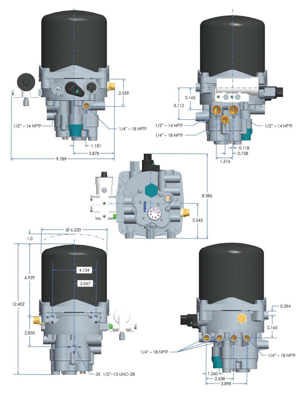
12 Dimensions Page 11
13 ModulAir Dryer Installation Guidelines Haldex recommends that all installations follow SAE standard J2383 and much of the following information is extracted from SAE J2383, with certain unique requirements specific to the ModulAir dryer family. Mounting Position The air dryer should be mounted in a location with sufficient space around it to facilitate service and to provide visual access for periodic inspection. The air dryer should be mounted in an area where it is protected from tire or wheel road splash. The air dryer, including mounting brackets, lines and fittings should be mounted in a protected location such that minor mechanical damage to the vehicle will not damage the air system integrity. The air dryer must be mounted with the exhaust port pointed downward. The air dryer must be mounted to avoid excessive heat sources (175º F max). The air dryer mounting method must be rigid enough to avoid vibration which could damage the desiccant or dryer. The air dryer must not incline in any direction more than 15 from vertical position. The air dryer must have at least 0.5 in (12.5 mm) free space above the cartridge canister to allow for removal during service. Mounting Method The ModulAir dryer uses the standard 3-bolt pattern shown in the figure below. c A A= 2.83 in (72mm) B = 4.13 in (105mm) C = 2.07 in (52.5 mm) Drill Clearance Hole Diameter for 1/2 UNC 28 Bolt B Page 12
14 Air Lines and Fittings Air Lines To prevent moisture accumulation, the compressor discharge line should slope continuously downhill from the compressor to the dryer without any dips which exceed ½ the line diameter. If this is not possible, the line should run vertically straight upward at the compressor to a height that will permit a downhill sloping run to the dryer. The compressor discharge line size, length, and material must be such that the inlet temperature is typically no more than 160 F (71 C), and no less than 77 F (25 C) above the lowest ambient temperature. Lower dryer inlet temperatures should be avoided to minimize the risk of freeze-ups in the discharge line or dryer inlet fitting. Higher dryer inlet temperatures should be avoided to minimize the risk of heat damage to the dryer seals and/or to avoid loss of drying performance. Fittings The use of restrictive fittings in the compressor discharge line should be avoided. These restrictive fittings impede the airflow and contribute to increased freezing potential. Avoid the use of 90 elbows where possible The air dryer must not incline in any direction more than 15 from vertical position. The air dryer must have at least 0.5 in (12.5 mm) free space above the cartridge canister to allow for removal during service. Use Teflon tape on fittings very sparingly, keeping in mind that it could break loose and contaminate the air valve seals. Page 13
15 ModulAir Dryer Installation Guidelines Important Precautions and Preparations All company and vehicle manufacturer s safety procedures must be followed when installing the ModulAir dryer. Always wear proper personal protective equipment, including approved eye glasses. Never work on or under a vehicle unless it is parked on a level surface and its wheels are blocked to prevent it from moving. Never work on a vehicle air brake system when the engine is running. Where circumstances require that the engine be in operation, extreme caution should be used to prevent personal injury resulting from contact with moving, rotating, leaking, heated or electrically charged components. Drain all air pressure from the air system before beginning any installation, service, or repair. Never connect or disconnect a hose or line containing pressure. Never remove a component plug unless it is certain that all system pressure has been depleted. Never exceed recommended component or system pressures. Do not attempt to install, remove, disassemble or assemble a component until all recommended procedures have been read and are fully understood. Use only the proper tools and observe all precautions pertaining to the use of those tools. Use only genuine Haldex replacement parts, components and kits. Replacement hardware, tubing, fitting, etc should be of equivalent size, type and strength as original equipment and be designed specifically for such applications and systems. Components with stripped threads or damaged part should be replaced rather than repaired. Repairs requiring machining or welding should not be attempted unless specifically approved and stated by the vehicle or component manufacturer. Prior to returning the vehicle to service, make certain all components and systems are restored to their proper operating condition. Page 14
16 Mounting Guidelines 1. Locate ModulAir dryer in an area with sufficient space that will allow for service and visual access for inspection. 2. Dryer should be mounted away from direct tire splash. 3. The dryer exhaust, or purge port must point downward. Reference page Mounting location must be selected to avoid excessive heat. 5. Mounting location must be rigid and not susceptible to excess vibration. 6. Compressor discharge line must slope downward, without dips and 90 fittings should be avoided. 7. Mounted dryer should not have more than 15 inclination from vertical. 8. Ensure that there is a minimum of ½ above dryer for serviceability of the desiccant cartridge. 9. The ModulAir dryer has a standard SAEJ bolt mounting pattern and can be used to mount directly to a frame member. However, a mounting bracket can be used if necessary. Basic Installation Steps Mounting 1. Park the vehicle on a level surface, apply the parking brakes and always block the wheels. 2. Stop the engine. 3. Drain the air pressure from all reservoirs before beginning any work on the vehicle. 4. Following the vehicle manufacturer s recommended procedures, deactivate the electrical system in a manner that removes all electrical power from the vehicle. 5. Locate the dryer to the intended mounting position in accordance with the above mounting guidelines and install ½ - 28 minimum grade 5 bolt with lock washer, tightening to ft-lb of torque. Electrical 6. For those dryers with a heater, it must be connected to the vehicle power supply. Locate a circuit with the correct voltage that is energized, or hot, when the ignition is ON. The current draw is 8 amps at 12 V and 4 amps at 24 V. A amp fuse is recommended in this line. Connect the one heater lead to this hot wire. 7. Connect the other heater lead to a good electrical ground on the vehicle chassis or within an electrical junction box. Care should be taken to protect the grounding connection from the water and other contaminant ingression. Page 15


17 Connecting Air Lines 8. Connect a suitable compressor discharge line to the ½ NPT dryer inlet port marked 11, making sure that the line slopes down from the compressor to the air dryer. The compressor discharge line material should be wire braided Teflon hose, copper tubing or a combination of both. The length of compressor discharge line should be selected so that the dryer inlet does not exceed 170 F (77 C). This can generally be accomplished with 12 to 15 feet of air compressor discharge length. Excessive discharge length should also be avoided to prevent moisture from freezing. The dryer inlet must be greater than 40 F (5 C). 9. From both the primary and secondary reservoirs connect suitable ½ NPT line to the air dryer ports for the primary (21) and secondary (22) circuits. 10. Connect a ¼ NPT fitting with nylon line or equivalent to the control port (4) of the dryer. The other end of the control line will typically be connected back to the compressor. 11. Connect ¼ NPT line to those auxiliary circuits desired. Any additional ports not used can be plugged with the appropriate ¼ NPT pipe plug. Teflon tape or other approved sealant should be used sparingly on the pipe plug to prevent leakage. Installation Tip: While minimum diameters are specified, larger line diameters generally improve performance, service life, and reduce operating temperatures, particularly in severe applications. Do not attempt to adjust or service the pressure protection valve, as this could cause system pressure loss and automatic parking brake application. Pressure protection valve springs are under load and could cause serious personal injury if distribution housing is removed. Page 16
18 Testing the ModulAir Dryer Before placing the vehicle into service, perform the following tests: 1. Close all reservoir drain valves and ensure all lines are connected properly. 2. Assure transmission is in neutral, start engine. Build up system air pressure to governor cut-out and note that the air dryer purges with an audible exhaust of air. Air should continue to flow from the dryer exhaust as the dryer purges and regenerates the desiccant for approximately seconds. Testing Tip: The pressure gauges for the primary, secondary and auxiliary circuits will begin to fill at different pressures. Typically, the primary will fill first, with the secondary and auxiliaries to follow shortly after. 3. Actuate the service brakes a number of times to reduce system air pressure to governor cut-in. Ensure that the system once again builds to full required system pressure and that the dryer purges when the compressor cuts out (compressor unloads). 4. It is recommended that the vehicle be tested for leakage using the following procedure to assure that the air dryer will not cycle excessively: A. Apply the parking brakes, run engine to build system pressure to governor cut-out and allow pressure to stabilize for at least 1 minute at idle. B. Observe the dash gauge pressures for 2 minutes and note any pressure drop. Pressure drop should not exceed 4 psi with brake pedal released and 6 psi with brakes applied. Any noticeable leakage must be repaired to avoid excessive cycling. C. On vehicles using system regeneration, which is how the ModulAir dryer functions, the vehicle air gauges will drop slightly as the dryer purges. 5. Charge cycle time: during normal, daily operation, the compressor should recover from governor cut-in to governor cut-out in 90 seconds or less depending upon the engine RPM and vehicle vocation. 6. Purge cycle interval: During normal vehicle operation, the air compressor must remain unloaded for a minimum of 30 seconds between charge cycles. This minimum purge time is required to ensure complete regeneration of the desiccant. Page 17
19 ModulAir Dryer Troubleshooting Guide Problem Cause Solution Water in air system Constant exhaust of air at air dryer Excessive compressor cycling 1. Desiccant contaminated (oil) or over saturated. 2. Leaks in air system. 3. Governor loose or not functioning properly. 1. Dryer unloader valve not closing. 2. Governor loose or not functioning properly. 3. Compressor unloader not functioning (compressor not unloading). 1. Excessive leaks in air system. 2. Broken, contaminated or defective unloader valve. 3. Undersized compressor, duty cycle of compressor should not exceed 25%. 1. Replace desiccant cartridge. Wipe dryer base clean Check compressor for excessive oil passage. 2. Tighten air connections. Use soapy water to recheck for leaks following the Testing the ModulAir Dryer section. 3. Check governor gasket for damage and replace if necessary. Reassemble governor and tighten governor bolts to recommended manufacturer s torque specifications. 1. At compressor cut-out there must be a slight blow of regenerated air from the exhaust port of the dryer for approx seconds. If air flow continues, after purge cycle, remove and inspect unloader valve of the dryer for obstruction or damage. If damaged, then replace. If obstructed or dirty, then clean and reinstall. 2. Check governor gasket for damage and replace if necessary. Reassemble governor and tighten governor bolts to recommended manufacturer s torque specifications lb in. 3. Repair or replace compressor unloader. 1. Tighten air connections, soap connection and recheck for leaks. 2. Clean or replace compressor unloader valve. 3. Reduce air demand or use a compressor with greater air output. Safety valve is open 1. Desiccant cartridge is plugged or overly contaminated. 2. Ice blockage inside dryer. 3. Excessive system pressure. 1. Excessive oil passage from compressor or high amount of carbon buildup. Check for worn compressor (piston rings, gaskets, etc.). Replace desiccant cartridge. 2. Check heater function. 3. Repair or replace governor. Short life of dryer or desiccant cartridge Short purge cycle of dryer (less than 12 seconds) 1. Air at inlet of dryer exceeds 170 F (77 C). 1. Loose governor or poor gasket seal. 2. Regeneration valve not functioning. 1. Extend length of compressor discharge line; see Installation Guidelines and Installation Procedure sections. The 170 F (77 C) dryer inlet temperature can usually be achieved with 12 to 15 of compressor discharge line. 1. Tighten governor bolts. If leakage still occurs, then replace gasket or complete governor. 2. Replace regeneration valve. Page 18
20 ModulAir Dryer Service Parts Kit Information General Instructions The following parts are available for service and maintenance of the ModulAir dryer. Each service kit includes specific instructions. 1. Desiccant cartridge: O-ring for cartridge: DQ Retaining collar: Governor kit: KN Regeneration valve: Turbo protection valve: DQ Heater assembly: 12V: V: Unloader valve: DQ Safety valve: KN31527 Page 19
21 Notes: Page 20
22 Haldex offers proprietary vehicle technology solutions to the global vehicle industry within specific niches. We focus on products to improve safety, the environment and vehicle dynamics. We are enhancing our competitive capabilities and building long-term customer relationships through high performance, low total costs to the customer through the product s service life, ethical business practices and commitment to long-term partnerships. Haldex operations are divided into four business areas: Commercial Vehicle Systems, Hydraulic Systems, Garphyttan Wire and Traction Systems. 2008, This material may contain Haldex trademarks and third party trademarks, trade names, corporate logos, graphics and emblems which are the property of their respective companies. The contents of this document may not be copied, distributed, adapted or displayed for commercial purposes or otherwise without prior written consent from Haldex. Austria Haldex Wien Ges.m.b.H. Vienna Tel:: Fax: info.at@haldex.com Belgium Haldex N.V./S.A. Balegem (Ghent) Tel.: Fax: info.be@haldex.com Brazil Haldex do Brasil Ind. e Com, Ltda. São Paulo Tel.: Fax: info.br@haldex.com Canada Haldex Ltd Guelph, Ontario Tel.: Fax : info.ca@haldex.com China Haldex International Trading Co. Ltd. Shanghai Tel.: Fax: info.cn@haldex.com France Haldex Europe SAS Weyersheim (Strasbourg) Tel.: Fax: info.eur@haldex.com Germany Haldex Brake Products GmbH Heidelberg Tel.: Fax: info.de@haldex.com Hungary Haldex Hungary Kft. Szentlörinckáta Tel.: Fax: info.hu@haldex.com India Haldex India Limited Nasik Tel.: Fax info.in@haldex.com Italy Haldex Italia SRL Biassono (Milan) Tel.: Fax: info.it@haldex.com Poland Haldex Sp. z.o.o. Praszka Tel.: Fax: info.pl@haldex.com Russia OOO Haldex RUS Moscow Tel.: Fax: info.ru@haldex.com South Korea Haldex Korea Ltd. Seoul Tel.: Fax: info.kr@haldex.com Spain Haldex España S.A. Parets del Valles (Barcelona) Tel.: Fax: info.es@haldex.com Sweden Haldex Brake Products AB Landskrona Tel.: Fax: info.se@haldex.com United Kingdom Haldex Ltd. Newton Aycliffe Tel.: Fax: info.gbay@haldex.com Haldex Brake Products Ltd. Redditch Tel.: Fax: info.gbre@haldex.com USA Haldex Brake Products Corp. Kansas City, MO Tel.: Fax: info.us@haldex.com Commercial Vehicle Systems L31241 US 10/08????
PURest Air Dryer Installation and Maintenance
 PURest Air Dryer Installation and Maintenance L31170 Rev. 4/04 The Haldex PURest is a desiccant type dryer that effectively removes moisture, oil and contaminants from the compressed air system. This reduces
ModulAir Air Dryer with External Purge Tank - Changeover from Bendix AD-IS for Peterbilt Installation. Air Dryer Mounting Bracket (Item 1)
") Instruction Guide L31259 11/10 ModulAir Air Dryer with External Purge Tank - Changeover from Bendix AD-IS for Peterbilt Installation Air Dryer Mounting Bracket (Item 1) Tank Mounting Bracket (Item 19)
Instruction Guide L31259 11/10 ModulAir Air Dryer with External Purge Tank - Changeover from Bendix AD-IS for Peterbilt Installation Air Dryer Mounting Bracket (Item 1) Tank Mounting Bracket (Item 19)
Designers Manual. Haldex Single Air Drier
 Designers Manual Haldex Single Air Drier Designer s manual 1 DESIGNER S MANUAL Haldex Single Air Drier Contents Introduction 2 Air drying procedure and performance 3 Procedure 3 SAE J2384 Air Dryer Test
Bulletin No.: PRO Effective Date: 7/15/94 Cancels: PRO dated 5/1/92 Page: 1 of 6
 Technical Bulletin Bulletin No.: PRO-08-19 Effective Date: 7/15/94 Cancels: PRO-08-19 dated 5/1/92 Page: 1 of 6 Subject: The Holset Type E & QE Compressor Air Supply System with Bendix Air Dryer & Holset
SD Bendix Dryer Reservoir Module with AD-IS Air Dryer DESCRIPTION
 SD-98-9808 Bendix Dryer Reservoir Module with AD-IS Air Dryer INTEGRATED MOUNTING BOLTS (3) DESICCANT CARTRIDGE AUXILIARY DELIVERY PORTS (5) SECONDARY GOVERNOR AD-IS AIR DRYER PART NUMBER STAMPED HERE
DRY AIR SYSTEMS, INC Metro Boulevard Maryland Heights, Missouri (314) fax (314)
 fax (314)") DRY AIR SYSTEMS, INC. 2655 Metro Boulevard Maryland Heights, Missouri 63043 (314) 344-1114 fax (314) 344-0677 HD SERIES DRIERS TABLE OF CONTENTS WHY AN AIR DRYER 3 WHAT IS A DESICCANT AIR DRYER 3 Desiccant
DRY AIR SYSTEMS, INC. 2655 Metro Boulevard Maryland Heights, Missouri 63043 (314) 344-1114 fax (314) 344-0677 HD SERIES DRIERS TABLE OF CONTENTS WHY AN AIR DRYER 3 WHAT IS A DESICCANT AIR DRYER 3 Desiccant
SD Bendix AD-IS EverFlow Assembly BENDIX AD-IS EVERFLOW ASSEMBLY
 SD-08-2417 Bendix AD-IS EverFlow Assembly EVERFLOW MODULE BENDIX EVERFLOW ELECTRONIC MODULE RES (2) BENDIX AD-IS EVERFLOW ASSEMBLY BENDIX AD-IS AIR DRYER PURAGUARD MEDALLION VALVE PRESSURE PROTECTION VALVES
System Saver HP Air Dryer
 Maintenance Manual MM-1736 System Saver HP Air Dryer Revised 12-17 Service Notes About This Manual This manual provides service and repair procedures for Meritor WABCO s System Saver HP air dryer. Before
SECTION air supply system + WARNING: + NOTE: GENERAL DESCRIPTION COMPRESSED AIR RESERVOIRS / 1.
 08-000.02/ 1 2011JA14 SECTION 08-000.02 GENERAL DESCRIPTION See Figure 1 for a schematic diagram of the. See the Nova LFS parts manual for a detailed schematic of the. The function of the vehicle s is
Module 7: Air Supply System
 Terms and Definitions Components of the Air Supply System Basic Functions of the Air Supply System Parts of a Compressor Characteristics of Compressors Loading and Unloading Process Characteristics of
SD Bendix AD-IS and AD-IS PuraGuard (Oil Coalescing) Air Dryer and Reservoir Systems
 Air Dryer and Reservoir Systems") Bendix AD-IS and AD-IS PuraGuard (Oil Coalescing) Air Dryer and Reservoir Systems SD-08-2418 RES GOVERNOR (2) VALVE PRESSURE PROTECTION VALVES (4) DESICCANT CARTRIDGE (STANDARD SHOWN) DESICCANT CARTRIDGE
Bendix AD-IS and AD-IS PuraGuard (Oil Coalescing) Air Dryer and Reservoir Systems SD-08-2418 RES GOVERNOR (2) VALVE PRESSURE PROTECTION VALVES (4) DESICCANT CARTRIDGE (STANDARD SHOWN) DESICCANT CARTRIDGE
Air Dryer Application Guidelines
 Revised 11-16 Technical Bulletin Revised 1 Technical 11-16 Bulletin Air Dryer Application Guidelines System Saver Series and System Saver Twin How to Obtain Additional Maintenance, Service and Product
System Saver TWIN Air Dryer. Maintenance Manual 35 Revised 11-02
 System Saver TWIN Air Dryer Maintenance Manual 35 Revised 11-02 Service Notes This publication provides maintenance and service procedures for Meritor WABCO s System Saver TWIN air dryers. The information
Section 4-3. Service - Air Dryer
 Section 4-3 Service - Air Dryer UPPER UPPER OUTER SHELL OUTER SHELL LOWER LOWER END COVER END COVER CONTROL CONTROL SUPPLY SUPPLY DELIVERY WIRING HARNESS CONNECTION DELIVERY WIRING HARNESS CONNECTION EXTENDED
... Desiccant Cartridges Conventional and Oil Separator Cartridges (OSC) ... products derived from proven Knorr-Bremse Technology. Product Information
 ... products derived from proven Knorr-Bremse Technology. Product Information") Commercial Vehicle Systems Product Information...... Desiccant Cartridges Conventional and Oil Separator Cartridges (OSC)...... products derived from proven Technology Product Information Desiccant Cartridges
Commercial Vehicle Systems Product Information...... Desiccant Cartridges Conventional and Oil Separator Cartridges (OSC)...... products derived from proven Technology Product Information Desiccant Cartridges
SD Bendix AD-IP Integral Purge Air Dryer DESCRIPTION. The AD-IP air dryer has three female pipe thread air connections identified as follows:
 SD-08-2414 Bendix AD-IP Integral Purge Air Dryer DESICCANT CARTRIDGE SADDLE MOUNTING BRACKET SAFETY MOUNTING STRAP SAFETY CONTROL LOWER MOUNTING BRACKET CONTROL HEATER & THERMOSTAT CONNECTOR SUPPLY HEATER
SD Bendix AD-1 and AD-2 Air Dryers
 SD-08-2403 Bendix AD-1 and AD-2 Air Dryers AD-1 AIR DRYER AD-2 AIR DRYER FIGURE 1 The air dryer collects and removes moisture and contaminants before the air reaches the first reservoir. It is distinctly
Brakemaster air dryers. The complete fleet guide to operation, trouble-shooting, and service procedures
 Brakemaster air dryers The complete fleet guide to operation, trouble-shooting, and service procedures The problem is moisture and contamination. The solution is SKF Brakemaster air dryers. With the ongoing
HEATLESS DESICCANT AIR DRYER INSTRUCTION & MAINTENANCE MANUAL
 HEATLESS DESICCANT AIR DRYER INSTRUCTION & MAINTENANCE MANUAL H-Series & 203 THRU 223 SERIES ARROW PNEUMATICS, INC. REGENERATIVE DRYER DIVISION 2111 WEST 21ST STREET BROADVIEW, IL 60155 708-343-9595 708-343-1907
SD Bendix AD-IP Integral Purge and AD-IP PuraGuard Oil Coalescing Integral Purge Air Dryers
 SD-08-2414 Bendix AD-IP Integral Purge and AD-IP PuraGuard Oil Coalescing Integral Purge Air Dryers DESICCANT CARTRIDGE CABLE MOUNTING BRACKET MOUNTING CABLE CONTROL DELIVERY DISCHARGE SAFETY VALVE HEATER
INSTALLATION AND SERVICE MANUAL FOR THE SERIES 1000-P FAN SERIES (PNEUMATIC CONTROL) SERIES 1000-H FAN SERIES (HYDRAULIC CONTROL) GEN 2
 SERIES 1000-H FAN SERIES (HYDRAULIC CONTROL) GEN 2") INSTALLATION AND SERVICE MANUAL FOR THE SERIES 1000-P FAN SERIES (PNEUMATIC CONTROL) SERIES 1000-H FAN SERIES (HYDRAULIC CONTROL) GEN 2 Publication No. 01906 Revision 0 Printed in Canada 1.1 INTRODUCTION
INSTALLATION AND SERVICE MANUAL FOR THE SERIES 1000-P FAN SERIES (PNEUMATIC CONTROL) SERIES 1000-H FAN SERIES (HYDRAULIC CONTROL) GEN 2 Publication No. 01906 Revision 0 Printed in Canada 1.1 INTRODUCTION
INSTALLATION AND OPERATION MANUAL STEAM COIL BASE CONVECTION STEAMER MODEL SCX-16
 INSTALLATION AND OPERATION MANUAL STEAM COIL BASE CONVECTION STEAMER MODEL SCX-16 CROWN FOOD SERVICE EQUIPMENT LTD. 70 OAKDALE ROAD, DOWNSVIEW, (TORONTO), ONTARIO, CANADA, M3N 1V9 TELEPHONE: (416) 746-2358,
INSTALLATION AND SERVICE MANUAL FOR THE SERIES 2000 & SERIES 3000 FAN SERIES GEN 2
 INSTALLATION AND SERVICE MANUAL FOR THE SERIES 2000 & SERIES 3000 FAN SERIES GEN 2 (PNEUMATIC CONTROL AND HYDRAULIC CONTROL) PUBLICATION No. 01900 Revision 2 Printed in Canada 1.1 INTRODUCTION Thank you
WILKERSON MODELS DE3, DE4 AND DE5 COMPACT HEATLESS AIR DRYERS
 INSTRUCTION MANUAL FOR WILKERSON MODELS DE3, DE4 AND DE5 COMPACT HEATLESS AIR DRYERS DE3 - DE5 OPERATIONS GENERAL This instruction manual covers the installation, operation, maintenance and troubleshooting
INSTALLATION AND SERVICE MANUAL FOR THE SERIES 2000 & SERIES 3000 FAN SERIES GEN 1
 INSTALLATION AND SERVICE MANUAL FOR THE SERIES 2000 & SERIES 3000 FAN SERIES GEN 1 (PNEUMATIC CONTROL AND HYDRAULIC CONTROL) PUBLICATION No. 01524 Revision 15 Printed in Canada 1.1 INTRODUCTION Thank
ACT Cartridge Dust Collector
 IOM-101-1 ACT Cartridge Dust Collector Installation and Operation Manual ACT Dust Collectors CAUTION! Accidents happen, be careful and always follow all local and federal regulations! Fires and explosions
HT650 TM FAN DRIVE SERVICE INSTRUCTIONS
 HT650 TM FAN DRIVE SERVICE INSTRUCTIONS When unpacking your product, remove all components and inspect them to ensure that no damage occurred during shipping. If any components are missing or damaged,
SuperKlean Washdown Products
 February 2012 DURAMIX 8000 INSTALLATION AND MAINTENANCE INSTRUCTIONS **DO NOT THROW AWAY AFTER INSTALLATION** **SAVE AND DISPLAY PROMINENTLY WHERE THIS EQUIPMENT IS USED** WARNING HIGH PRESSURE AND HOT
SFD. Suburban Filter Dryer. User Manual Installation Instructions
 SFD Suburban Filter Dryer User Manual Installation Instructions Take your air system into the future with patented, molecular sieve technology used in the SFD regenerative cycle compressed air drying system.
OPERATING MANUAL MODEL AIR 1500TM AIR DRYER
 OPERATING MANUAL MODEL AIR 500TM AIR DRYER Puregas, LLC 226-A Commerce St. Tel: 800-52-535 Broomfield, Colorado Fax: 303-657-2205 P/N P0255 REV A, 02/9/4 TABLE OF CONTENTS.0 GENERAL... 3 2.0 SPECIFICATIONS...
PuraGuard. Maintenance Kit Rebuild Kit Replacement Drain Cock
 Air Dryers 08 PuraGuard PuraGuard Service Pc. No. 800691 One Supply & one Delivery Port (see arrow symbol on PuraGuard top cover for air flow) Maintenance Kit...5006788 Rebuild Kit...5006789 Replacement
INSTALLATION AND SERVICE MANUAL FOR THE TAC1000-P FAN SERIES (PNEUMATIC CONTROL) TAC1000-H FAN SERIES (HYDRAULIC CONTROL)
 TAC1000-H FAN SERIES (HYDRAULIC CONTROL)") INSTALLATION AND SERVICE MANUAL FOR THE TAC1000-P FAN SERIES (PNEUMATIC CONTROL) TAC1000-H FAN SERIES (HYDRAULIC CONTROL) Publication No. 01553 Revision 8 Printed in Canada 1.1 INTRODUCTION This manual
INSTALLATION AND SERVICE MANUAL FOR THE TAC1000-P FAN SERIES (PNEUMATIC CONTROL) TAC1000-H FAN SERIES (HYDRAULIC CONTROL) Publication No. 01553 Revision 8 Printed in Canada 1.1 INTRODUCTION This manual
OK, OKA, OKAF; ELD; ELDM; ELH; OKC; SC; SCA; SCAF; OK-LN; OKA-LN; OKAF-LN.
 INSTALLATION, OPERATION & SERVICE MANUAL FOR COOLER TYPES OK, OKA, OKAF; ELD; ELDM; ELH; OKC; SC; SCA; SCAF; OK-LN; OKA-LN; OKAF-LN. 1. Introduction This manual is a guide for the installation, maintenance
Model OP155 Air Dryer
 "Teamwork & Communication" Model OP155 Air Dryer Operating Manual with Parts Identification OP155-INST June 15, 1998 Issue 2 GUSMER CORPORATION A Subsidiary of Gusmer Machinery Group, Inc. One Gusmer Drive
AXPR Wall Mounted Axial Panel Fans
 Bulletin 78-January-03-06 AXPR Wall Mounted Axial Panel Fans INSTALLATION, OPERATION, AND MAINTENANCE MANUAL This publication contains the installation, operation and maintenance instructions for the AXPR
10/09/2014. SFD Air Dryer Owner s Manual
 10/09/2014 SFD Air Dryer Owner s Manual Table of Contents WARNING Read, understand and follow safety precautions and instructions in this manual and in the labels attached to the dryer system. Failure
Advanced Troubleshooting Guide for Air Brake Compressors *
 This troubleshooting guide obsoletes and supersedes all previous published troubleshooting information relative to Bendix air compressors. Advanced Troubleshooting Guide for Air Brake Compressors * The
NEWGATE TECHNOLOGIES, INC.
 www W.newgatetechnologies.com NEWGATE TECHNOLOGIES, INC. Installation & Operations Manual SYNERGY Series High Inlet Temperature Refrigerated Air Dryers Models SYNERGY 025 ~ SYNERGY 125 Includes Safety
Operator s Manual CHILLER ( CH SERIES) Models: CH750, CH751, and CH951
 Models: CH750, CH751, and CH951") IMI CORNELIUS REMCOR INC 500 REGENCY DRIVE GLENDALE HEIGHTS, IL 60139 2268 Telephone (800) 551 4423 Facsimile (866) 394 5140 Operator s Manual CHILLER ( CH SERIES) Models: CH750, CH751, and CH951 Part
IMI CORNELIUS REMCOR INC 500 REGENCY DRIVE GLENDALE HEIGHTS, IL 60139 2268 Telephone (800) 551 4423 Facsimile (866) 394 5140 Operator s Manual CHILLER ( CH SERIES) Models: CH750, CH751, and CH951 Part
Models Series Series
 Models 3180-Series 3181-Series INDUSTRIAL DIAPHRAGM PUMPS Commercial Duty, 3 GPM/1 LPM FEATURES Sealless Easy Installation Run Dry Ability Flow to 3 GPM/1 LPM Self-Priming Low Amp Draw Thermal Overload
User manual Flushing device VAS 6337/1a
 User manual Flushing device VAS 6337/1a 2 Content Safety warnings 3 Flushing with R134a refrigerant 4 1.0 Preparing the Vehicle AC System 4 1.1 Connecting the recovery recharge Unit 6 1.2 Flush procedure
SKF Brakemaster. Air dryer solutions
 SKF Brakemaster Air dryer solutions The problem is moisture and contamination. For four decades and literally trillions of miles, commercial carriers have relied on SKF products to improve fleet efficiency,
A COMPLETE GUIDE TO OPERATION, TROUBLESHOOTING AND SERVICE PROCEDURES 2005 DRY AIR SYSTEMS Group (04/05)
") A COMPLETE GUIDE TO OPERATION, TROUBLESHOOTING AND SERVICE PROCEDURES 2005 DRY AIR SYSTEMS Group 457364 (04/05) The JP Dryer System An effective solution to the problems of oil, water vapor and contaminants
A COMPLETE GUIDE TO OPERATION, TROUBLESHOOTING AND SERVICE PROCEDURES 2005 DRY AIR SYSTEMS Group 457364 (04/05) The JP Dryer System An effective solution to the problems of oil, water vapor and contaminants
π H-6621 INDUSTRIAL DEHUMIDIFIER WARNINGS SPECIFICATIONS uline.com WATER REMOVAL ELECTRICAL REQUIREMENTS BUILT-IN ELECTRICAL SAFETY
 π H-6621 INDUSTRIAL DEHUMIDIFIER 1-800-295-5510 uline.com WARNINGS Plug into a grounded 3 prong outlet. Do not remove ground prong. Do not use an adapter. Do not use an extension cord if possible. Failure
POWER VENTER. Model: PVE Series
 POWER VENTER Model: PVE Series CONTENTS Typical Venting System Components... System Operation... Power Venter Sizing... Installation Safety Instructions... Installation of Power Venter... Connecting Power
EXHAUST PURGE DESICCANT AIR DRYER INSTRUCTION & MAINTENANCE MANUAL MODEL RE-231 THROUGH RE-252
 EXHAUST PURGE DESICCANT AIR DRYER INSTRUCTION & MAINTENANCE MANUAL MODEL RE-231 THROUGH RE-252 ARROW PNEUMATICS, INC. REGENERATIVE DRYER DIVISION 500 NORTH OAKWOOD RD LAKE ZURICH, IL,60047 PHONE # (847)
201 Series Dryers Features and Benefits...3 Dimensions...4 How to Order...5 Product Specifications...5
 201 Series Dryers.....................................................................3-5 Features and Benefits..............................................................................3 Dimensions......................................................................................4
CH750, CH751 & CH951 CHILLERS
 CH750, CH751 & CH951 CHILLERS Operator s & Installation Manual Release Date: April 19, 2002 Publication Number: 91256 Revision Date: March 25, 2014 Revision: F Visit the Cornelius web site at www.cornelius.com
Model Series Series
 PumpAgents.com - Click here for Pricing/Ordering Model 36800-Series 36900-Series ELECTRIC WATER SYSTEM PUMPS Automatic Multi-Outlet FEATURES Self-Priming Diaphragm Design Allows Dry Running Built-in Discharge
Models Series Series
 Models 31800-Series 31801-Series INDUSTRIAL DIAPHRAGM PUMPS 4 GPM/15 LPM FEATURES Self-Priming Easy Installation Can run dry without damage Low Amp Draw Flow to 4 GPM/15 LPM Compact Size Thermal Overload
COMPRESSED AIR DRYER. SAFETY... Page 2 MAINTENANCE... Page 5. INSTALLATION... Page 3 PARTS AND KITS... Page 6
 OWNERS MANUAL BOSS COMPRESSED AIR DRYER Distributed by Air & Vacuum Process, Inc. Phone: 281-866-9700 Fax: 281-866-9717 Email: sales@airvacuumprocess.com SAFETY... Page 2 MAINTENANCE... Page 5 INSTALLATION...
Standard and CELDEK Evaporative Cooler Modules Installation, Operation, and Maintenance Manual
 Standard and CELDEK Evaporative Cooler Modules Installation, Operation, and Maintenance Manual Standard Evaporative Cooler CELDEK Evaporative Cooler RECEIVING AND INSPECTION Upon receiving unit, check
P6500W Air Dryer User s Guide
 P6500W Air Dryer User s Guide 1. Welcome & Congratulations Congratulations on your purchase of a new PUREGAS P6500W Air Dryer! We here at PUREGAS are very proud of our products and we are committed to
Model Series ELECTRIC WATER SYSTEM PUMP. PumpAgents.com - buy pumps and parts online. Model Series. Automatic Multi-Outlet FEATURES
 PumpAgents.com - Click here for Pricing/Ordering Model 36950-2 Series ELECTRIC WATER SYSTEM PUMP Automatic Multi-Outlet FEATURES Self-Priming Diaphragm Design Allows Dry Running Built-in Discharge Check
SAN RAPHAEL PRESSURE LITE VITREOUS CHINA SIPHON JET TOILET
 SAN RAPHAEL PRESSURE LITE VITREOUS CHINA SIPHON JET TOILET BEFORE YOU BEGIN HOW TO USE THESE INSTRUCTIONS Please read these instructions carefully to familiarize yourself with the required tools, materials,
CHILLERS. Operator s & Installation Manual
 CHILLERS MODELS: CH750, CH751 & CH951 Operator s & Installation Manual Release Date: April 19, 2002 Publication Number: 91256 Revision Date: May 5, 2010 Revision: D Visit the IMI Cornelius web site at
rev3 INSTALLATION & OPERATION MANUAL OIL CIRCULATING HEATING SYSTEM MODEL OSM
 216279-000 rev3 INSTALLATION & OPERATION MANUAL OIL CIRCULATING HEATING SYSTEM MODEL OSM IDENTIFYING YOUR SYSTEM IOM216279-000 The HOTSTART heating system is designed to heat fluids for use in marine
MARTIN Insertable Dust Collector
 MARTIN Insertable Dust Collector Go to MARTIN Insertable Dust Collector web page Operator s Manual M3416 Important MARTIN ENGINEERING HEREBY DISCLAIMS ANY LIABILITY FOR: DAMAGE DUE TO CONTAMINATION OF
INGERSOLLrAND AIR COMPRESSORS CAUTION: HMD SERIES AIR DRYERS MODELS 18 THROUGH 385 OPERATORS/ INSTRUCTION MANUAL REPLACEMENT PARTS
 INGERSOLLrAND AIR COMPRESSORS HMD SERIES AIR DRYERS MODELS 18 THROUGH 385 OPERATORS/ INSTRUCTION MANUAL REPLACEMENT PARTS CAUTION: For HMD Models 84 Through 385 ONLY 1. Remove Dryer Chambers And Protective
PURGE STANDARD IPC AIR DRYER LABEL
 Bendix AD-9 and AD-9 IPC (Integrated PuraGuard Coalescing) Air Dryers SD-08-2412 EXTENDED PURGE STANDARD IPC AIR DRYER LABEL OUTER SHELL END COVER CONTROL PORT SUPPLY PORT DELIVERY PORT WIRING HARNESS
Niles Steel Tank Hot Water Generator Installation and Operation Manual
 Niles Steel Tank Hot Water Generator Installation and Operation Manual Contents: Contents 1 Hazard definitions 1 1. General Information.... 2 Availability... 3 Optional Control Packages... 5 2. Installation....
Instructions for Model E782 Betman Cleaning System (Cleaner/Rinser/Rinser/Dryer)
") 1 2 Esma Inc. PO Box 734 450 W. Taft Drive South Holland, IL 60473 708-331-1855 800-276-2466 FAX 708-331-8919 Introduction Instructions for Model E782 Betman Cleaning System (Cleaner/Rinser/Rinser/Dryer)
1 2 Esma Inc. PO Box 734 450 W. Taft Drive South Holland, IL 60473 708-331-1855 800-276-2466 FAX 708-331-8919 Introduction Instructions for Model E782 Betman Cleaning System (Cleaner/Rinser/Rinser/Dryer)
SECTION AIR COMPRESSORS AND ACCESSORIES
 PART 1 GENERAL 1.01 WORK INCLUDED SECTION 11370 AIR COMPRESSORS AND ACCESSORIES A. This specification includes air compressors with air dryers. B. Furnish, install, start-up, and test air compressors and
INSTALLATION INSTRUCTIONS
 Web Site: http//www.atomic4.com e-mail: thomas.stevens@cox.net INSTALLATION INSTRUCTIONS INDIGO ELECTRONICS AT-4T THERMOSTAT KIT ATOMIC 4 - ELECTRIC FWC This Indigo Thermostat Kit is designed for use with
T-SERIES Air Conditioner. T20 Model INSTRUCTION MANUAL nvent Rev. C P/N
 T-SERIES Air Conditioner T20 Model INSTRUCTION MANUAL Rev. C P/N 89114993 TABLE OF CONTENTS Warranty and Return Policy... 2 IMPORTANT NOTICE... 2 RECEIVING THE AIR CONDITIONER... 3 HANDLING AND TESTING
DURANGO 12V Heater HF
 DURANGO 12V Heater HF-100012 1 Product description 2 Operating principle 3 Mounting recommendations 4 Troubleshooting 3 Safety instructions Page 1 of 5 1 Product description The DURANGO heater consists
Component. Maintenance. Manual Z SERIES. Evaporator Assembly
 Component Maintenance Manual with Illustrated Parts List for Z21-701-SERIES Evaporator Assembly 1 of 16 Record of Revision REVISION ISSUE POSTED NO: DATE DATE INSERTED BY: 2 of 16 List of Effective Pages
Dual Column Dehydrating Breather Manual
 Dual Column Dehydrating Breather Manual DCB-MANUAL 1.6 Read and understand this manual prior to operating or servicing the products. SPX Transformer Solutions, Inc., Service & Components Division U.S.
GENERAL 2004 HVAC SYSTEMS. Manual HVAC System - Sorento SPECIFICATIONS. Fig. 1: Air Conditioner Specifications Courtesy of KIA MOTORS AMERICA, INC.
 Fig. 2: Blower & Evaporator Unit Specifications 2004 HVAC SYSTEMS Manual HVAC System - Sorento GENERAL SPECIFICATIONS AIR CONDITIONER Fig. 1: Air Conditioner Specifications BLOWER AND EVAPORATOR UNIT HEATER
Blower Purge Desiccant Compressed Air Dryer. HBP SERIES 500-4,300 SCFM ( nm 3 /h)
") Blower Purge Desiccant Compressed Air Dryer HBP SERIES 500-4,300 SCFM (850-7306 nm 3 /h) HBP Series Blower Purge Desiccant Compressed Air Dryers HBP SERIES DRYERS PRODUCE 100% EFFICIENT AIR SYSTEMS HBP
Blower Purge Desiccant Compressed Air Dryer HBP SERIES 500-4,300 SCFM (850-7306 nm 3 /h) HBP Series Blower Purge Desiccant Compressed Air Dryers HBP SERIES DRYERS PRODUCE 100% EFFICIENT AIR SYSTEMS HBP
HTD. High Temperature Non-Cycling Refrigerated Compressed Air Dryers. Operation & Maintenance Manual. MODELS HTD 21 thru HTD 100
 HTD High Temperature Non-Cycling Refrigerated Compressed Air Dryers Operation & Maintenance Manual MODELS HTD 21 thru HTD 100 - TABLE OF CONTENTS - 1.0 GENERAL 2 1.1 How to use this manual 1.2 Symbols
Instruction Manual - Anti-Siphon Ejector Chlorine & Sulfur Dioxide 500 PPD (10 kg/h) Maximum Capacity
 Maximum Capacity") - Anti-Siphon Ejector Chlorine & Sulfur Dioxide 500 PPD (10 kg/h) Maximum Capacity 100 PPD (2 kg/h) Chlorine or Sulfur Dioxide 250 & 500 PPD (5 & 10 kg/h) Chlorine or Sulfur Dioxide Anti-Siphon Ejector
- Anti-Siphon Ejector Chlorine & Sulfur Dioxide 500 PPD (10 kg/h) Maximum Capacity 100 PPD (2 kg/h) Chlorine or Sulfur Dioxide 250 & 500 PPD (5 & 10 kg/h) Chlorine or Sulfur Dioxide Anti-Siphon Ejector
Installation and Operation Guide
 Hot Water on Demand Installation and Operation Guide Thermostatic Series 18kW, 21kW, 24kW 118 º F www.atmorusa.com Table of Contents Description Page Safety Guidelines...2 Technical Information...3 Plumbing...
WineZone Ceiling Mount Ductless Split 15
 WineZone Ceiling Mount Ductless Split 15 Requires an HVAC technician to install and charge with R-22 refrigerant. Easy to install. Unit plugs into wall outlet. Industrial grade unit for longer life. Indoor
OPERATING MANUAL MANUAL WATER BASE GUN CLEANERS UM120W UNI-RAM CORPORATION ONTARIO CANADA PATENTS
 OPERATING MANUAL MANUAL WATER BASE GUN CLEANERS UM120W PATENTS USA 4,788,836 CANADA USA 5,213,117 ENGLAND EUROPE 0300248 ITALY SWEDEN 0300248 GERMANY FRANCE 8110528.0 JAPAN UNI-RAM CORPORATION ONTARIO
UHIR Series. Horizontal or Vertical Mounting Industrial / Commercial Electric Unit Heater. Owner s Manual
 UHIR Series Horizontal or Vertical Mounting Industrial / Commercial Electric Unit Heater Owner s Manual This manual covers installation, maintenance and repair parts. Read carefully before attempting to
TECHNICAL DATA. Wet 26a. February 22, 2009
 February 22, 2009 Wet 26a 1. DESCRIPTION The Viking Alarm Check Valve serves as a check valve by trapping pressurized water above the clapper and preventing reverse flow from sprinkler piping. The valve
FUTURE AIR SOLUTIONS OIL FREE SCROLL COMPRESSORS
 FUTURE AIR SOLUTIONS OIL FREE SCROLL COMPRESSORS The Most Advanced Technologies for High-Quality air High-precision processing technology is required to produce the components that make up a Scroll Compressor.
PVE SERIES POWER VENTER SYSTEM MANUAL
 PVE SERIES POWER VENTER SYSTEM MANUAL Contents Page I. Typical Venting System Components 2 II. System Operation 3 III. Power Venter Sizing 3,4 IV. Installation Safety Instructions 5,6 V. Installation of
Models: GW/R-T GW/R-2-T GW/R-3-T
 Part# GW/R-T-OM 1/12/04 TN Models: GW/R-T GW/R-2-T GW/R-3-T This manual contains important information concerning the installation and operation of the gun washers listed above. Read manual thoroughly
02 COOLING SYSTEM 02 COOLING SYSTEM COOLING SYSTEM INDEX. 1. General Specifications... 65
 REV. 02 / 01.11.13 COOLING SYSTEM INDE 1. General... 64 2. Specifications... 65 3. Structure and Operation... 65 3.1. Cooling System... 65 3.2. Radiator... 65 3.3. Water Pump... 65 3.4. Thermostat... 65
CELDEK Evaporative Cooler Module Installation, Operation, and Maintenance Manual. CELDEK Evaporative Cooler
 CELDEK Evaporative Cooler Module Installation, Operation, and Maintenance Manual CELDEK Evaporative Cooler RECEIVING AND INSPECTION Upon receiving unit, check for any interior and exterior damage, and
Adsorption dryer PDAD. (en) Operating instructions g [ ]
![Adsorption dryer PDAD. (en) Operating instructions g [ ]](/thumbs/80/81991997.jpg "Adsorption dryer PDAD. (en) Operating instructions g [ ]") Adsorption dryer PDAD (en) Operating instructions 8068814 1701g [8068816] Original instructions Installation and commissioning are to be carried out only by qualified personnel in accordance with the operating
Adsorption dryer PDAD (en) Operating instructions 8068814 1701g [8068816] Original instructions Installation and commissioning are to be carried out only by qualified personnel in accordance with the operating
OPERATING & MAINTENANCE MANUAL INDUSTRIAL DIRECT FIRED DIESEL/KEROSENE HEATERS IC 25
 OPERATING & MAINTENANCE MANUAL INDUSTRIAL DIRECT FIRED DIESEL/KEROSENE HEATERS IC 25 NOT FOR DOMESTIC USE SPACE HEATING ONLY Made By: Spitwater Australia Pty Ltd 953 Metry St North Albury, NSW, Australia
SuperKlean Washdown Products
 DURAREEL DR8 & DR8S INSTALLATION AND MAINTENANCE INSTRUCTIONS **DO NOT THROW AWAY AFTER INSTALLATION** **SAVE AND DISPLAY PROMINENTLY WHERE THIS EQUIPMENT IS USED** GENERAL WARNINGS High pressure and hot
Owner's Manual TABLE OF CONTENTS
 40MAQ High Wall Ductless System Sizes 09 to 36 Owner's Manual TABLE OF CONTENTS PAGE A NOTE ABOUT SAFETY... 2 GENERAL... 2 PART NAMES... 3 FUNCTION BUTTONS... 4 DISPLAY PANELS... 5 REMOTE CONTROL... 6
L A signature series TA T N E RE O, A L L A T S IN
 signature series COMMERCIAL STEAM GENERATORS INSTALLATION, OPERATION AND MAINTENANCE MANUAL INSTALLATION MANUAL COMMERCIAL STEAM GENERATOR SIGNATURE SERIES (SS) INTRODUCTION Steam Sauna manufactures steam
T-Series Air Conditioner T20 Model
 INSTRUCTION MANUAL T-Series Air Conditioner T20 Model Protecting Electronics. Exceeding Expectations. McLean Cooling Technology 11611 Business Park Blvd N Champlin, MN 55316 USA Tel 763-323-8200 Fax 763-576-3200
OWNER S MANUAL CAVN SERIES SELF CONTAINED RETRACTABLE NOZZLE VACUUM SEALER WITH GAS PURGE
 OWNER S MANUAL CAVN SERIES SELF CONTAINED RETRACTABLE NOZZLE VACUUM SEALER WITH GAS PURGE WHAT S IN THE PACKAGE? This Operation Manual. (1) Vacuum Sealer. (1) E-(unit size) Heating Element, inside the
P4200PM / P5000PM Remote Air Dryer User s Guide
 P4200PM / P5000PM Remote Air Dryer User s Guide 1. Welcome & Congratulations Congratulations on your purchase of a new PUREGAS P4200PM / P5000PM Air Dryer! We here at PUREGAS are very proud of our products
Installation, Operation, and Maintenance Manual Balston Model 76-01, 76-02, 76-10, and Membrane Air Dryers
 Installation, Operation and Maintenance Manual Installation, Operation, and Maintenance Manual Balston Model 76-01, 76-02, 76-10, 76-20 and Membrane Air Dryers Model 76-20 Models 76-01, 76-02, 76-10 Figure
INSTALLATION INSTRUCTIONS
 Web Site: http//www.atomic4.com e-mail: thomas.stevens@cox.net INSTALLATION INSTRUCTIONS INDIGO ELECTRONICS AT-4T THERMOSTAT KIT ATOMIC 4 - MECHANICAL FWC This Indigo Thermostat Kit is designed for use
POWER VENTER SYSTEM. Model: PVO-300, PVO-600
 POWER VENTER SYSTEM Model: PVO-300, PVO-600 Included is one ETL and cetl listed Power Venter to be used primarily with a single 120VAC controlled oil fired furnace, boiler, or water heater. The PVO may
Standard and CELDEK Evaporative Cooler Modules Installation, Operation, and Maintenance Manual
 Standard and CELDEK Evaporative Cooler Modules Installation, Operation, and Maintenance Manual Standard Evaporative Cooler CELDEK Evaporative Cooler RECEIVING AND INSPECTION Upon receiving unit, check
HALLMARK INDUSTRIES INC. HALLMARK INDUSTRIES INC. Safety WARNING WARNING. Must reset the voltage! Shallow Well Jet Pumps
 Safety Important Safety Instructions SAVE THESE INSTRUCTIONS - This manual contains important instructions that should be followed during installation, operation, and maintenance of the product. Save this
WATLOW IND. WATROD Modular Duct Heater Installation & Maintenance Manual I&M NUMBER: Page: 1 Date:6/11/2008 Rev: 2
 I&M NUMBER: 316-42-15-1 Page: 1 _ Pre Installation Check to make sure that heater received is the same as that ordered. Elements may come in contact with each other during shipment. Minor adjustments to
SAVE THESE INSTRUCTIONS
 Built-In Dishwasher Dishwashers Write the model and serial numbers here: Model # Serial # You can find them on the tub wall just inside the door or. the lower part of back. Installation Instructions DDW1802W
Item # /2" NPT, 2 STAGE AIR FILTER/DRYER SYSTEM INSTRUCTIONS
 Item #31727 1/2" NPT, 2 STAGE AIR FILTER/DRYER SYSTEM INSTRUCTIONS THE ROCKWOOD 1/2" NPT AIR FILTER/DRYER includes a high-capacity, drainable Coalescing Filter and Bowl to trap moisture and other impurities
INSTALLATION INSTRUCTIONS FOR FANLESS MAKE-UP AIR MODEL NER (USA)
") INSTALLATION INSTRUCTIONS FOR FANLESS MAKE-UP AIR MODEL NER (USA) July 2017 VERSION 1.3 Please read instructions carefully before installation. This NER unit is a packaged fan-less fresh air make-up unit
INSTALLATION INSTRUCTIONS FOR FANLESS MAKE-UP AIR MODEL NER (USA) July 2017 VERSION 1.3 Please read instructions carefully before installation. This NER unit is a packaged fan-less fresh air make-up unit
REVISED AIR GOVERNOR LINES CX AND CH MODEL CHASSIS WITH ASET AC ENGINE
 SERVICE BULLETIN (Not applicable to Mack Trucks Australia) NUMBER: SB-531-011 DATE: 7/12/04 MODEL: CX, CH REVISED AIR GOVERNOR LINES CX AND CH MODEL CHASSIS WITH ASET AC ENGINE Effective June 2004, stainless