GETTING STARTED. May 15th, version 1.0.1
|
|
|
- Brandon Porter
- 5 years ago
- Views:
Transcription

1 GETTING STARTED May 15th, 2015 version
2 Disclaimers Information in this document is subject to change without notice and does not represent a commitment on the part of SWARM TECHNOLOGIES LLC D.B.A. SmartBee Controllers. SWARM TECHNOLOGIES LLC D.B.A. SmartBee Controllers provides this document as is, without warranty of any kind, expressed or implied, including, but not limited to, the implied warranties of fitness or merchantability for a particular purpose. SWARM TECHNOLOGIES LLC D.B.A. SmartBee Controllers may make improvements and/or changes in this manual or in the product(s) and/or the program(s) described in this manual at any time. Trademarks and copyright SWARM TECHNOLOGIES LLC, SmartBee Controllers, and the SmartBee logo are trademarks or registered trademarks in the United States and other countries worldwide. All other trademarks mentioned in this document are the property of their respective owners SWARM TECHNOLOGIES LLC D.B.A. SmartBee Controllers. All rights reserved. 2
3 Table of Contents Disclaimers Trademarks and copyright Out of the Box: Getting Started Plug in / Power Up Power and Network Buttons Connecting to Hive Login to Your Hive First Time Setup Create a Room Connecting Devices Control Devices Sensor Devices Disable Automation Device Initialization Device Discovery Alert Device Network LED Device Manager Sensors Room Initialization Thresholds Irrigation Schedules Lighting Schedules Plug in Your Devices Concepts Rooms Sensor Hardware and Data Aggregation Thresholds and Appliances Deadbands 3


4 Out of the Box: Getting Started Plug in / Power Up Plug the included 5V power adapter into the Hive. DO NOT press either of the Hive s buttons now. The Hive Gateway buttons and LEDs are depicted in this diagram. 4

5 After plugging in your Hive Gateway you will observe the following series of events: As the Hive powers up, observe green LED 1 3 ON SOLID. In seconds, green LED 5 begins a slow blink Main System Initialization In seconds, green LED 4 begins a slow blink Network Initialization After 1 minute, green LED 1 5 ON SOLID This indicates that your Hive is started and running in HotSpot mode. Power and Network Buttons The Power Off and Network buttons have different functions when clicked versus held. Do not press either of the buttons now. Quickly pressing the Power Off button will begin the power down sequence, ultimately powering off your Hive. To restart the Hive after powering it down, remove and re insert the power adapter. The Power Off button does not start the Hive. Holding the Power Off button for 10+ seconds will restore factory settings. You will lose all settings, updates, and data. Your Hive will return to WiFi hotspot mode. Quickly pressing the Network button configures the Hive for Ethernet using DHCP. LED 4 will begin to blink while the network is being reconfigured. If this fails, LED 4 will blink rapidly and the network setup will revert to the previous setting. Holding the Network button for 5+ seconds configures the Hive as a WiFi hotspot (factory default). LED 4 will begin to blink while the network is being reconfigured. If this fails, LED 4 will blink rapidly and the network setup will revert to the previous setting. Connecting to Hive Your hive is configured as a WiFi hotspot out of the box. Through a WiFi enabled device, identify the network named Smartbee FFFFFF (where FFFFFF are any six hexadecimal digits.) Connect to this WiFi network and enter the default password of beebee833. Wait up to a minute for connection to be fully established. You are now connected to your Hive. If you cannot locate the Smartbee FFFFFF network, press and hold the NETWORK button until LED 4 begins to blink. This will reconfigure the Hive as a Wifi Hotspot. Observe LEDs as above. 5

6 Login to Your Hive Now that you have connected to your Hive s WiFi hotspot, you may log in to the Hive webapp. Open a browser and navigate to You will be prompted to login. The default URL and Port are correct for now. The default login for the Hive is : User: super_bee Password: beebee833 6
7 First Time Setup The first time you log in to your Hive, you will be greeted: Choose Get Started. You will then be asked to configure the current time. You will then have the opportunity to name your Hive. s that come from your Hive will use this name. 7

8 You will then arrive at the Dashboard, which will be empty: 8


9 Create a Room Now create a room. Go to Settings > Room Manager. Click Add Room. 9


10 Name your new room and click Save. By default, the room s grow cycle counter will start when the room is created. To delay the start of the count, you can create a room with an inactive grow cycle. For now, leave the grow cycle Active. Click Dashboard in the upper left to return to the Dashboard. Your new room will be displayed: 10
11 Connecting Devices Control Devices The Stinger SS1 and Stinger SS4 devices allow the Hive to activate electrical appliances remotely over the wireless mesh network. Place these devices near the equipment you wish to control, and plug the Stinger(s) in to 110V wall current. Do not plug your electrical appliances into the Stinger yet. Stinger SS1 devices are useful for any single circuit up to a 15 amp load. Stinger SS4s can also serve a 15 amp load on any of its four circuits, but this is also the maximum total current through the device. We suggest maximizing the useful circuits on the SS4 by spreading the circuits among smaller loads. Sensor Devices Sensor devices include the LTH, LTH+CO 2, and the WCSM. Sensor devices are battery powered and transmit data through the wireless mesh network back to the Hive. These devices must be activated out of the box. The sensor devices are equipped with a long lasting, rechargeable Lithium Ion battery. The sensor devices are also equipped with solar panels capable of recharging the battery under brightly lit conditions. When sensor devices are shipped, a battery protection circuit is enabled. First, for LTH and LTH+CO 2 devices, locate the battery disconnect switch on the side of the device. Slide the switch to the ON (up) position. The left most LED will be ON SOLID. Second, for all sensor devices, use the included mini B USB 5V adapter to activate them by simply plugging them in for the first time. We also suggest leaving them to charge for 6 12 hours out of the box. Your sensors are now powered and can transmit data. 11

12 Disable Automation While connecting and configuring your hive, it is a good idea to disable automation in the room(s). Click Dashboard in the upper left corner to return to the dashboard. Click the new room you created earlier to enter the room details page In the room details page slide the Device sliders to OFF: Temp Controls: Heating Devices Cooling Devices Humidity Controls: Humidifier Devices Dehumidifier Devices Irrigation Controls Irrigation Devices Lighting Controls Lighting Devices This disables appliance automation until we are ready. In the example below we show Humidity Controls. 12
13 Device Initialization Now that your SmartBee Controllers devices are powered, Use your browser to log in to the Hive Gateway webapp and then choose Settings > Permit Join. This allows devices to join your network for up to two minutes. 13


, a status LED will be ON SOLID when the device is networked.")
14 Device Discovery Alert You will begin to receive alerts as devices are discovered. You can match the radio address displayed in the Alert with the address in Device Manager (and partially included as the default device name) and with the sticker on the device itself. Device Network LED All devices also have a green LED that indicates network connectivity. On all sensor devices (LTH, LTH+CO 2, and WCSM), the right most green LED will have a very slow heartbeat blink when it is connected to a network. On all control devices (SS1 & SS4), a status LED will be ON SOLID when the device is networked. The status LED on an SS4 is located on the left side of the device behind the ventilation grill. On the SS1, the Status LED is labeled on the front of the device. SS4 Status LED SS1 Status LED 14


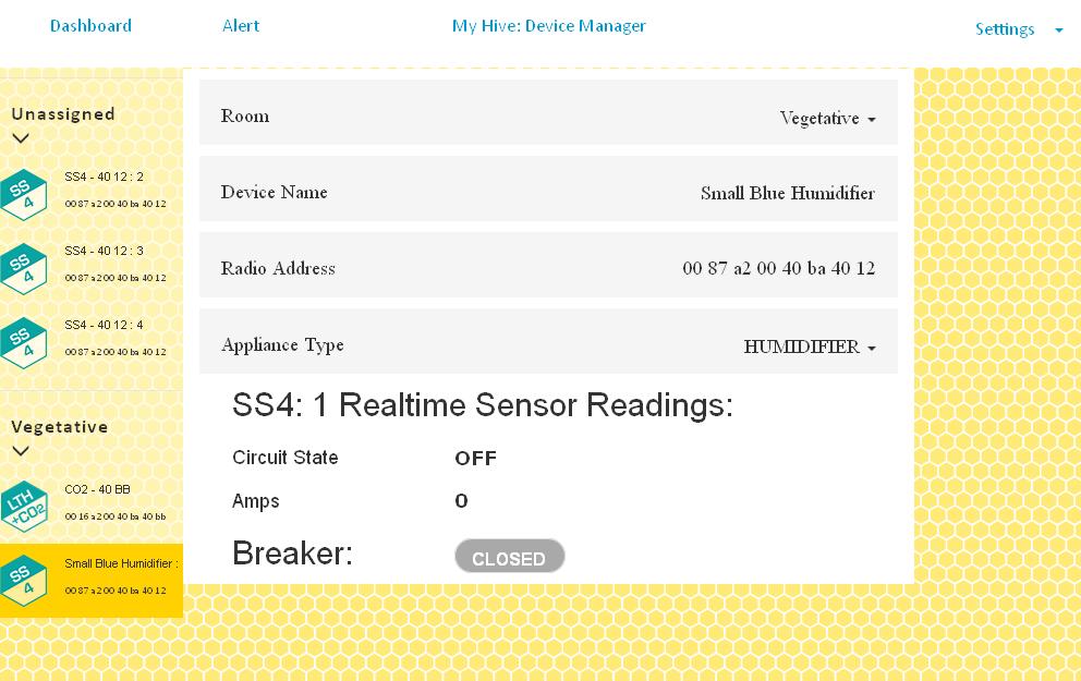
15 Device Manager Use Device Manager to verify that the Hive is receiving data from your devices. Go to Settings > Device Manager Sensors Verify each sensor device appears in the device manager. If an LTH or LTH+CO 2 device does not appear as you expect, first disconnect the charging cable. Then slide the battery disconnect switch to the OFF (down) position and then back to ON and reconnect the cable. Immediately go to Settings > Permit Join to allow the sensor to connect to the mesh. If a WCSM device does not appear, press the Reset button on the side. Immediately go to Settings > Permit Join to allow the sensor to connect to the mesh. Now use the Device Manager to place your sensors into your room. Placing a sensor into a room causes that sensor to contribute its data to that room s aggregates. To assign your sensors to the room, in Device Manager: Choose the sensor device in the Unassigned list. The device is not currently assigned to any room, so you will find it in the Unassigned list. 15

16 In the main panel, assign the device to a room by selecting from the Room drop down. You should at this point assign a memorable name if so desired. 16

17 Control Devices 17


18 Before proceeding further, you may wish to test the circuit using the Toggle Circuit feature in the Device Manager. Toggle the circuit on and observe the circuit LED for expected results. 18

19 In the main panel assign the circuit to a room by selecting from the Room drop down. If you do not need to remotely control a particular circuit, you may leave that circuit Unassigned. Define the appliance type for the circuit. 19


20 You should at this point also set a memorable name if so desired. 20
21 21


22 Room Initialization Return to the dashboard and enter the room or rooms you have defined and added sensors to. Observe that the sensor values are within expected ranges. Click Dashboard in the upper left corner. From the dashboard, click anywhere on the room you created earlier. 22

23 Thresholds On the Temp Controls and Humidity Controls pages are the threshold and appliance settings. The Temp Controls page has two groups of set point controls labeled DAYTIME and NIGHTTIME. Each pair of set points governs the room s appliances for the given time of day. When the room s aggregate temperature falls below the lower set point during the relevant time of day, all of the room s heaters will be activated until the temperature rises above the set value plus deadband. Likewise, when the room s aggregate temperature rises above the upper set point during the relevant time of day, the room s cooling devices will be activated until the temperature falls below the upper set value minus deadband. Similarly, the Humidity Controls page also has set points grouped by time of day. When the room s aggregate relative humidity falls below the lower set point during the relevant time of day, the room s humidifiers will be activated. When the room s aggregate relative humidity rises above the upper set point during the relevant time of day, the room s dehumidifiers will be activated. 23


24 Set your daytime and nighttime temperature and humidity thresholds by moving the sliders on the Temp Controls and Humidity Controls pages. Enable automation for devices by moving the sliders from OFF to AUTO. 24

25 Irrigation Schedules As an example, we will create a single scheduled irrigation event. Irrigation events recur daily according to their scheduled times. To create a scheduled irrigation event, on the Irrigation Controls page, Click Add schedules 25

26 A dialog appears where you can create one or more scheduled irrigation events. Define the Start Time and Duration Click Add Click Finished adding schedule 26
. To disable prevention, drag this slider to 100%.")
27 Click Save Changes. Irrigation is also governed by a pair of thresholds: the upper threshold sets the point at which the growing medium is considered too wet. Scheduled irrigation events will not occur if the growing medium is too wet (an Alert occurs instead). To disable prevention, drag this slider to 100%. The lower threshold sets the point at which the growing medium is considered too dry. If the growing medium is too dry, an emergency irrigation will occur. The emergency irrigation period is one minute long followed by a 15 minute rest before reevaluation. To disable emergency irrigation, drag this slider to 0%. 27

28 Lighting Schedules On the Lighting Controls page, set the lighting schedule. Unlock the schedule control by clicking the lock icon in the center. Choose your desired day length (12 Hour Cycle, 18 Hour Cycle, or 24 Hour Cycle) 28

29 Click and/or rotate the dial to choose your desired start time. Click the lock icon again to save your changes and lock the controls. 29

30 Ensure the upper lighting overheat set point is reasonably high for your environment. Lighting will be disabled if the temperature in the room exceeds the upper threshold as a safety measure. If lighting is so disabled, the lights will be re enabled when the temperature crosses the lower set point. Plug in Your Devices Now that you have defined your room and configured the relevant thresholds and schedules, you can plug your equipment into their assigned Stinger circuits and automate your grow. Be sure that the equipment that your Stinger circuits will control is in an ALWAYS ON state, such that when power is supplied the appliance activates. 30
31 Concepts Rooms The Hive uses the concept of a room to group sensors, aggregate their data, and use that data to control appliances. A room is basically a control group. The sensors assigned to a room use the room s thresholds to control the rooms appliances. A room also counts the days it has been active in order to show the current day of the plants grow cycle. Sensor Hardware and Data Aggregation Sensors are assigned to a room. When a sensor is assigned to a room, it begins to contribute to the room s sensor aggregates. For each kind of sensor data (temperature, humidity, etc), the average value of all sensors in the room is calculated. This becomes the room s aggregate value for that type of sensor data. If the room has no sensors of a given type, the aggregate value will be N/A. Sensors report data periodically (typically every 45 seconds) and when the Hive receives new sensor data, it recalculates the aggregate values. The most recent update time is always displayed with the room aggregates so you can be sure that the data is recent and observe updates. Thresholds and Appliances An appliance is any Stinger circuit that has been assigned to the room and assigned an appliance type. All circuits assigned to the same appliance type are activated together and controlled as a group. A threshold is a user definable set point. Thresholds generally come in pairs that contain the upper and lower values of the acceptable range. The Hive uses thresholds to control appliances. When the room aggregate for a given sensor data type crosses one of its thresholds, a specific type of appliance is activated until the room aggregate returns across the threshold. For example, if the average temperature reported by sensors in the room rises above the upper temperature threshold, the Hive will activate all of the Cooling appliances in the room until the temperature falls below the threshold and its deadband. Deadbands Different types of thresholds have different dead bands. Temperature: 5.4 F (3 C) Humidity: 5% Moisture in Grow Medium: 3% 31
Ion Gateway Cellular Gateway and Wireless Sensors
 Page 1 of 9 Account & Network Setup If this is your first time using the Ion Gateway online system site you will need to create a new account. If you have already created an account you can skip to the
Water Hero P-100. P-100 Components:
 Water Hero P-100 Thank you for purchasing the Water Hero P-100. The P-100 offers wholebuilding leak detection, mitigation, and water usage monitoring. P-100 Components: Main Controller Water Meter, Sensor
INSTALLATION AND OPERATION MANUAL
 INSTALLATION AND OPERATION MANUAL Water Hero P-100 Thank you for purchasing the Water Hero P-100, which offers whole-building leak detection and water conservation monitoring. This box contains: Main Controller
Peak Partners Web-Programmable Thermostat Homeowner s Manual. Look inside for a complete guide to the setup and operation of your new thermostat.
 Peak Partners Web-Programmable Thermostat Homeowner s Manual Look inside for a complete guide to the setup and operation of your new thermostat. Table of Contents Step 1: Getting Started...4-6 A. Thermostat
ENTOUCH ONE USER GUIDE
 ENTOUCH ONE USER GUIDE v4.0 MEASURE. MANAGE. SAVE. Contents Getting Started 3 Installation 7 Using the Setup Wizard 11 Using the Home Screen 12 Using the Main Menu 16 The Setup Menu 19 Using the Web Management
Monitoring Operator Guide. Access Control Manager Software Version
 Monitoring Operator Guide Access Control Manager Software Version 5.10.10 2018, Avigilon Corporation. All rights reserved. AVIGILON, the AVIGILON logo, ACCESS CONTROL MANAGER, ACM, ACM VERIFY AND TRUSTED
Dryer Controller M720
 User Manual Dryer Controller M720 Hardware version 2.00 Software version 2.00 Manual M720 Dryer controller Page 1 of 60 Document history Preliminary version: - Created in April, 2009 Hardware Version 2.00,
Installation, Configuration and User Manual
 Model 8826 System Controller Model 8826 System Controller Installation, Configuration and User Manual READ AND SAVE THESE INSTRUCTIONS WELCOME Thank you for choosing the Aprilaire HVAC Automation System.
Thermostat Guide Online Guide Brighten Conservation Program. Personal Reference Guide. Brighten ithermostat
 Thermostat Guide Online Guide Brighten Conservation Program Personal Reference Guide Brighten ithermostat Thermostat Guide Online Guide Brighten Conservation Program Welcome to your new Brighten ithermostat
For ios devices MYQ-G0301 MYQ-G0301C MYQ-G0301-D MYQ-G0301LA
 Smart Smart Garage Garage Hub Hub Manual Manual For ios devices MYQ-G0301 MYQ-G0301C MYQ-G0301-D MYQ-G0301LA by Before You Start To reduce the risk of SEVERE INJURY to persons: DO NOT enable the MyQ Smart
PRT-TS WiFi PRT-TS WiFi
 Model: PRT-TS WiFi Model: PRT-TS WiFi 1 Model: PRT-TS WiFi Table Of Contents Product Image 1 Frost Protection 16 Table of Contents 2 Heating ON/OFF 16 What is a Programmable Room Thermostat? Installation
Wiser Air User Interface Guide. Thermostat
 Wiser Air User Interface Guide Thermostat 2 User Guide Wiser Air Scope This document outlines the user interface features of the Wiser Air smart thermostat. It is intended to support individual users and
IndigoVision Alarm Panel. User Guide
 IndigoVision Alarm Panel User Guide THIS MANUAL WAS CREATED ON 2/21/2017. DOCUMENT ID: IU-AP-MAN002-4 Legal considerations LAWS THAT CAN VARY FROM COUNTRY TO COUNTRY MAY PROHIBIT CAMERA SURVEILLANCE. PLEASE
Table of Contents. Product Image 1 Locking/Unlocking the neoair 24 Table of Contents 2 Frost Protection 25 What is a Programmable Room Thermostat?
 Table of Contents Product Image 1 Locking/Unlocking the neoair 24 Table of Contents 2 Frost Protection 25 What is a Programmable Room Thermostat? 3-4 Power ON/OFF 26 Holiday Programming 27 Installation
Installation Manual. ATS Remote Annunciator Catalog 5350 DANGER WARNING D
 ASCO 5350 The ASCO 5350 ATS Remote Annunciator is listed under the Underwriter s Laboratories Standard UL-1008 for Automatic Transfer Switch accessories. This stand-alone device provides individual status
Avigilon System Integration Guide. for the Avigilon Control Center and Access Control Manager
 Avigilon System Integration Guide for the Avigilon Control Center and Access Control Manager 2014-2017, Avigilon Corporation. All rights reserved. AVIGILON, the AVIGILON logo, ACC, AVIGILON CONTROL CENTER,
User Manual. Dryer Controller M720
 User Manual Dryer Controller M720 Hardware version 1.00 Software version 1.00 Preliminary version Manual M720 Dryer controller Page 1 of 42 Document history Preliminary version: - Created in April, 2009
Cellular Monitoring System
 Cellular Monitoring System Wireless Temperature Monitoring Installation and Operation User s Manual Temperature Monitoring System used in: Temperature-controlled storage rooms and facilities Medical and
Cent$ible Power Users Manual
 Users Manual Welcome to Cent$ible Power Thank you for your participation in the Cent$ible Power pilot program. Your involvement is greatly appreciated. As a program participant, you are on the cutting
PWM. Solar Charge controller with Ethernet. Solar Smart PWM 20Amp. Hardware Description : Release : 19 June 2014
 Solar Charge controller with Ethernet Release : 19 June 2014 Hardware Version : Version 1 Firmware version 1 PC Application Software : Version 1.0.0.0 Hardware Description : The Solar Smart regulator was
WiFi Hints & Tips. Contents. WiFi Hints and Tips 1. Page No. Section No. Title
 WiFi Hints & Tips Contents Page No. Section No. Title Section.0 System Set-Up 3 Section. Sensor Set-Up 4-5 Section. Sensor Set-Up (Configuring Network) 6-9 Section.3 Sensor Set-Up (Configuring Settings)
Avigilon System Integration Guide. for the Avigilon Control Center and Access Control Manager
 Avigilon System Integration Guide for the Avigilon Control Center and Access Control Manager 2014-2016, Avigilon Corporation. All rights reserved. AVIGILON, the AVIGILON logo, AVIGILON CONTROL CENTER,
Operating Instructions Model: PRT-TS WiFi RF. 01/13 Version 1 Ref: PRT-TSWIFI RF
 Operating Instructions Model: PRT-TS WiFi RF 01/13 Version 1 Ref: PRT-TSWIFI RF Contents Page Setting up your WiFi Thermostat 2-6 Remote Connection Setup 6-8 Pairing with the Receiver 8-12 Display Symbols
User Guide ecobee ecobee 477 Richmond St West 2nd Floor, Toronto Ontario M5V 3E7 Canada Toll free
 User Guide ecobee3 2014 ecobee 477 Richmond St West 2nd Floor, Toronto Ontario M5V 3E7 Canada Toll free 1.877.932.6233 www.ecobee.com e3-ug-r001 1 Table of Contents Overview... 4 Getting Help... 4 Touch
G4S SMARTalarm User Guide
 G4S SMARTalarm User Guide CONGRATULATIONS WITH YOUR NEW SECURITY SYSTEM! We are glad that you have chosen G4S SMARTalarm. G4S is the largest supplier of security solutions in the world. We have invested
RE6100 Series Helix Security and Automation Platform
 CONFIGURATION Resolution Compatibles RE6100 Series Helix Security and Automation Platform C G UI D E Configuration Settings Table 1 - Panel Settings Table 2 - Zone Settings Table 3 - Device Settings Table
Cellular Monitoring System
 Cellular Monitoring System Wireless Temperature Monitoring Installation and Operation User s Manual For Firmware Versions 4.01-5.12 Temperature Monitoring System used in: Temperature-controlled storage
CODE ALERT Enterprise Software User Guide
 CODE ALERT Enterprise Software User Guide 2018 RF Technologies, Inc. All specifications subject to change without notice. All Rights Reserved. No Part of this work may be reproduced or copied in any form
Ontech GSM 9040/50. Reference Manual English -1 -
 Ontech GSM 9040/50 Reference Manual English -1 - Content Welcome... 5 This manual... 5 Text styles... 5 Support... 5 Disclaimer... 5 Overview... 6 Accessories... 6 External temperature sensor 9901... 7
Code Alert Series 30 Software User Guide
 Code Alert Series 30 Software User Guide 2018 RF Technologies, Inc. All specifications subject to change without notice. All Rights Reserved. No Part of this work may be reproduced or copied in any form
Why Vaillant? Because there s smart and then there s vsmart. Vaillant vsmart. The USER Guide
 Why Vaillant? Because there s smart and then there s vsmart Vaillant vsmart The USER Guide Allow me to introduce myself... What s in the box? Saving energy has never been so easy. Designed to work harmoniously
USER MANUAL DexTempTM 1000 Temperature Monitor (P/N: IR-1001) DexTempTM 1000 USB Non-Contact Temperature Monitor. User Manual.
 DexTempTM 1000 USB Non-Contact Temperature Monitor. User Manual.") USER MANUAL DexTempTM 1000 Temperature Monitor (P/N: IR-1001) DexTempTM 1000 USB Non-Contact Temperature Monitor User Manual 8690 Rev B Update: 10/24/2013 1 Table of Contents 1 Introduction.. 3 2 Host
USER MANUAL DexTempTM 1000 Temperature Monitor (P/N: IR-1001) DexTempTM 1000 USB Non-Contact Temperature Monitor User Manual 8690 Rev B Update: 10/24/2013 1 Table of Contents 1 Introduction.. 3 2 Host
PERS-3600 PERSONAL EMERGENCY REPORTING SYSTEM INSTALLATION & OPERATION INSTRUCTIONS
 PERS-600 PERSONAL EMERGENCY REPORTING SYSTEM BY BY INSTALLATION & OPERATION INSTRUCTIONS (760) 8-7000 USA & Canada (800) -587 & (800) 9-0 Toll Free FAX (800) 68-0 www.linearcorp.com CONTENTS CONTROL AREA
ModSync Sequencing System Installation & Operation Manual. For use with Fulton Steam Boilers.
 ModSync Sequencing System Installation & Operation Manual For use with Fulton Steam Boilers. Revision 3.0 8/21/2008 - 2 - Table of Contents Introduction Page 4 Features Page 4 Sequence of Operation Page
For Android devices MYQ-G0301 MYQ-G0301C MYQ-G0301D MYQ-G0301LA
 Smart Smart Garage Garage Hub Hub Manual Manual For Android devices MYQ-G0301 MYQ-G0301C MYQ-G0301D MYQ-G0301LA by Before You Start To reduce the risk of SEVERE INJURY to persons: DO NOT enable the MyQ
Disclaimer. Trademarks. Copyright. Warranty
 1 Disclaimer Trademarks Copyright Control4 makes no representations or warranties with respect to any Control4 hardware, software, or the contents or use of this publication, and specifically disclaims
Contents 1 Set Up 2 Gateway information 3 Operation of the App 4 Troubleshooting Description of sensors. 1 Set Up. 1.1 Connect the Gateway
 Contents 1 Set Up 2 Gateway information 3 Operation of the App 4 Troubleshooting Description of sensors 1 Set Up After downloading the Weatherhub app, follow these steps: 1.1 Connect the Gateway Connect
Room Alert. Room Alert 32E/W, 12E, 4E & 3E. Temperature & Environment Monitoring... Made Easy! User s Guide & Reference Manual
 Room Alert Temperature & Environment Monitoring... Made Easy! Room Alert 32E/W, 12E, 4E & 3E Phone 401.628.1600 Fax 401.628.1601 Web AVTECH.com User s Guide & Reference Manual AVT-151105-01 Contact Us
BAT WIFI SKU: IPD-BAT--WIFI
 PRODUCT MANUAL BAT WIFI SKU: IPD-BAT--WIFI Wi-Fi & Internet Alarm Communicator www.ipdatatel.com Product Manual BAT WIFI 1 QUICK REFERENCE BAT-WIFI GE Control Panel POS Com Data 6 5 4 3 G / Rx Y / Tx -
MODEL DZSP/ SZSP-1440 AIRCELL
 ACCM2-0513 55W30-AC0118 MODEL DZSP/ SZSP-1440 AIRCELL CONTROL MANUAL Control Adjustment and Operation Instructions CONTROL OVERVIEW/STANDARD FEATURES INITIALIZATION Section 1: Firmware blink code... 2
HEGA Ethernet Gateway Browser Interface Guide
 HEGA Ethernet Gateway Web Interface HEGA Ethernet Gateway Browser Interface Guide Table of Contents Introduction: Browser Interface Guide 3 Common Tasks: 4 Check-in Reports 5 Check-in Administration 5
DEFA HOME. User Manual Base Unit PRO
 DEFA HOME User Manual Base Unit PRO Table of Contents Overview 5 Logging into the app 9 Home 10 Calendar 13 Adding an event 14 Editing an event 15 Zones 16 Switch mode 17 Thermostat mode 19 Regulator
Hive Active Heating. Thermostat installation guide
 Hive Active Heating Thermostat installation guide Status Hot Central water heating Status Hot Central water heating Here s what you ll need to install Hive Active Heating A working gas central heating
icomfort E30 Smart Thermostat User Guide /2018 Supersedes Lennox Industries Inc. Dallas, Texas, USA
 icomfort E30 Smart Thermostat User Guide 507687-03 4/2018 Supersedes 507687-02 2018 Lennox Industries Inc. Dallas, Texas, USA Table of Contents Features... 3 Home Screen... 3 Temperature Dial Feature...3
NorthStar. System Requirements. Quick Install Guide
 NorthStar Quick Install Guide The instructions in this guide provide a basic overview for quickly getting results from a NorthStar lighting solution. They are intended to get you up and running quickly,
Sensor Cloud User Manual
 Sensor Cloud User Manual Table of Contents DEVICES TAB 4 1. DEVICE LIST 4 2. EXPAND ALL 4 3. EXPAND 4 4. STATUS 4 5. DEVICE 4 6. NAME 5 7. MONITORING INTERVAL 5 8. LAST ACTIVITY 5 9. VIEW 5 10. DELETE
Raytec Avigilon Integration User Guide Integrating Raytec Network Illuminators with Avigilon Control Center Document Revision 2.0
 Raytec Avigilon Integration User Guide Integrating Raytec Network Illuminators with Avigilon Control Center Document Revision 2.0 Table of Contents 1 INTRODUCTION... 3 1.1 OVERVIEW... 3 1.2 SOFTWARE COMPONENTS...
i.c³ User Guide For Helmer i.series Ultra-Low Freezers A/A
 i.c³ User Guide For Helmer i.series Ultra-Low Freezers 360175-A/A Document History Revision Date CO Supersession Revision Description A 18 APR 2014* 9275 n/a Initial release. * Date submitted or change
icomfort E30 Smart Thermostat User Guide
 icomfort E30 Smart Thermostat User Guide Table of Contents Features... 2 Home Screen... 3 Temperature Dial Feature... 3 Screen Elements... 3 Notifications... 4 Settings... 7 Wi-Fi... 7 Home Info... 8 Account...
RSC 1000 User Manual. Rev /25/16
 RSC 1000 User Manual Rev 2.2 10/25/16 CRITICAL APPLICATIONS DISCLAIMER QUEST CONTROLS PRODUCTS ARE NOT INTENDED OR AUTHORIZED FOR USE IN ANY APPLICATION THAT REQUIRES FAIL-SAFE OPERATION, OR ANY SYSTEM
C - B u s C - T o u c h U s e r s G u i d e C T Series
 C - B u s C - T o u c h U s e r s G u i d e 5 0 0 0 C T Series C-Touch Monochrome Touch Screen User's Guide 5000CT Series REGISTERED PATENT Table of Contents Section...Page 1.0 Product Range... 3 2.0
Follett Performance Plus
 Follett Performance Plus touchscreen user guide The next level of control in undercounter refrigeration Controller Operation - Performance Plus touchscreen Use and care of the LCD Performance Plus touchscreen
Alarm Coordination Connected Components Building Block. Quick Start
 Alarm Coordination Connected Components Building Block Quick Start Important User Information Solid state equipment has operational characteristics differing from those of electromechanical equipment.
GETTING STARTED WITH SMART THERMOSTAT
 GETTING STARTED WITH SMART THERMOSTAT This document is the property of Webee L.L.C.. The data contained here, in whole or in part, may not be duplicated, used or disclosed outside the recipient for any
status AW1 Plus WiFi Alarm System User Manual
 status AW1 Plus WiFi Alarm System User Manual Foreword Congratulations on your purchase of the AW1 Plus Alarm system. Before you commence installation we recommend that you unpack the product, familiarise
Protégé Eclipse LED Keypad User Manual PRT-KLES
 Protégé Eclipse LED Keypad User Manual PRT-KLES The specifications and descriptions of products and services contained in this manual were correct at the time of printing. Integrated Control Technology
status AW1 WiFi Alarm System Printed in China PA : AW1-UM-EN-V1.0 User Manual 2016 Chuango. All Rights Reserved.
 status 2016 Chuango. All Rights Reserved. Printed in China PA : AW1-UM-EN-V1.0 AW1 WiFi Alarm System User Manual Foreword Contents Congratulations on your purchase of the AW1 Alarm system. Before you commence
Professionally Monitored Service User Guide
 Midco SmartHOME Professionally Monitored Service User Guide Learn how to protect the things that matter most with this instruction guide for professionally monitored Midco SmartHOME service. 07 Midcontinent
Room Alert. Room Alert 32E, 12E, 4E & 3E. Temperature & Environment Monitoring... Made Easy! User s Guide & Reference Manual
 Room Alert Temperature & Environment Monitoring... Made Easy! Room Alert 32E, 12E, 4E & 3E Phone 401.628.1600 Fax 401.628.1601 Web AVTECH.com User s Guide & Reference Manual AVT-171212-1.1.0 Contact Us
CG500SKE SKYEYE GATEWAY USER MANUAL VERSION OCTOBER Disclaimers and Copyright
 CG500SKE SKYEYE GATEWAY USER MANUAL CG500SKE SkyEYE Gateway VERSION 1.2 26 OCTOBER 2014 Disclaimers and Copyright Nothing contained in this publication is to be construed as granting any right, by implication
IT801 Thermostat. User s Manual. The complete guide to the set up and operation of your new smart Wi-Fi thermostat.
 IT801 Thermostat User s Manual The complete guide to the set up and operation of your new smart Wi-Fi thermostat. The smart Wi-Fi thermostat system learns your comfort preferences, then finds opportunities
ComfortNet CTK04 Featuring the RedLINK Suite of Home Comfort Solutions
 ComfortNet CTK04 Featuring the RedLINK Suite of Home Comfort Solutions Agenda Comfort Advantage System Configurations Installing ComfortNet ComfortNet Control Set up Dehumidification and Defrost Settings
Model: Touch-RF. 1 Wireless Series
 Model: Touch-RF Model: Touch-RF 1 Wireless Series Table Of Contents Product Image 1 Locking the Keypad 18 Table of Contents 2 Temperature Control 19 What is a Programmable Room Thermostat? 3-4 Hot Water
Front page TBA from Marketing. Network and Device Monitoring. Starter Kit
 Front page TBA from Marketing Starter Kit Table of Contents Before you start... 3... 3 Activity 1 Current Network Device Status... 4 Activity 2 Node Voltage Monitoring... 5 Activity 3 Personnel Device
50110_HM-neoStat-2014_Layout 1 31/10/ :33 Page 1 neo
 neo Model: Available in : Sapphire Black and Glacier White 1 Wavin neo Table of Contents Product Image 1 Optional Features 19-22 Table of Contents 2 Re-calibrating the Thermostat 23 What is a Programmable
Lyric T6 & T6R Smart Thermostat
 Lyric T6 & T6R Smart Thermostat EN User Guide Lyric T6 Programmable Thermostat Lyric T6R Wireless Programmable Thermostat Lyric T6 & T6R Smart Thermostat Features Connects to the Internet so you can control
Salusfin Smart heating control: Installation Guide
 Salusfin Smart heating control: Installation Guide Detailed instruction can be found on our web site on all installation phases: FAQ s, Technical user guides and manufacturer s manuals. Video links can
ALC-PACK3. WiFi Alarm System with HD WiFi Camera. User Manual. Your Watchguard Wireless Security professional:
 status ALC-PACK3 WiFi Alarm System with HD WiFi Camera User Manual Your Watchguard Wireless Security professional: www.activeonline.com.au 1300 816 742 Foreword Congratulations on your purchase of the
User & Installer Manual SMT-400 "Enterprise" Wi-Fi Thermostat
 User & Installer Manual SMT-400 "Enterprise" Wi-Fi Thermostat Ver 1.01 May 2018 Great care has been taken in the preparation of this manual. Smart Temp Australia P/L takes no responsibility for errors
Agrifim A675CT Timer. Frequently Asked Questions
 Agrifim A675CT Timer Frequently Asked Questions 1 Contents How do I put batteries into the timer?.3 What type of batteries can be used?...3 How long will batteries last?...3 How do you program the timer?...3
Thermostat install guide
 Thermostat install guide 74_Hive Thermostat Install Guide_97mmx97mm_v3.indd 1 23/11/2015 14:0 Install Guide For Hive Active Heating the thermostat, receiver and hub are installed together so heating and
OWNER S MANUAL Venstar Inc. 08/07
 Digital Thermostat residential THERMOSTAT T1 900 7-DAY MABLE up to 3-heat & 2-cool HEAT COOL HEAT PUMP with HUMIDITY CONTROL Control up to 3 Heat & 2 Cool Stages 3 Configurable Outputs Adjustable 2nd &
Wireless Controls System Guide
 Wireless Controls System Guide As of September 6, 2018 Table of Contents 1.0 Introduction Why SALUS?... 1.1 Using this Manual.... 1.1 2.0 System Overview SALUS Wireless System Components with Internet
FreezeAlarm Dialer Pro
 FreezeAlarm Dialer Pro User Manual for FA-800E Thank you for purchasing our FreezeAlarm Dialer Pro. This instruction manual covers installation for model FA-800E. General Description The FA-800E automatically
AUTOMATION KIT. User s Manual. mysmartblinds.com/installation
 TM AUTOMATION KIT User s Manual mysmartblinds.com/installation QUICK START 1. Download the MySmart- Blinds app to your smart device from the App Store or Google Play. 2. Visit mysmartblinds.com/ installation
Owner s Manual. Part Number 33CS250-RC
 CONTENTS Page GENERAL... 1 CONFIGURATION... 1-4 Transmitter Display... 1 Transmitter Indicator... 1 Transmitter Front Panel Buttons... 1 Set Clock... 2 Programming Thermostat Schedules... 3 OPERATION...5
INTRODUCTION... VI I. IOS... 1
 Contents INTRODUCTION... VI PURPOSE... VI KEY FUNCTIONS OF THE SYSTEM... VI TERMS AND ABBREVIATIONS... VII SMART HEATER APPLICATION:... X ios:... x Android:... x Windows:... x PRIVACY POLICY... XI ADAX
INTRODUCTION... VI I. IOS... 1
 Contents INTRODUCTION... VI PURPOSE... VI KEY FUNCTIONS OF THE SYSTEM... VI TERMS AND ABBREVIATIONS... VII SMART HEATER APPLICATION:... X ios:... x Android:... x Windows:... x PRIVACY POLICY... XI ADAX
OWNER S MANUAL Venstar Inc. 08/07
 Digital Thermostat residential THERMOSTAT T1 800 7-DAY PROGRAMMABLE up to 3-heat & 2-cool HEAT COOL HEAT PUMP Control up to 3 Heat & 2 Cool Stages 3 Configurable Outputs Adjustable 2nd & 3rd Stage Timers
Milestone XProtect. Central 3.7 User s Manual
 Milestone XProtect Central 3.7 User s Manual Target Audience for this Document This document is intended for end users of the Milestone XProtect Central surveillance system monitoring solution, such as
D3D Wi-Fi GSM Smart Alarm System -User Manual
 D3D Wi-Fi GSM Smart Alarm System -User Manual D3D Wi-Fi / GSM Smart Alarm system (Model : D10). Please read all instructions carefully & follow steps for easy home installation. 1 P a g e D3D Wi-Fi / GSM
icomfort S30 User Guide
 icomfort S30 User Guide Color Touchscreen Programmable Wi-Fi Communicating Thermostat Dealer Contact Information 712-252-3007 800-747-3007 www.cwsuter.com (12U67) 507537-01 9/2015 Supersedes 7/2015 TABLE
ADT Pulse Mobile App Nest Thermostat
 ADT Pulse Mobile App Nest Thermostat Add the Nest Thermostat to your Pulse Mobile app to view the current status of the device and to control thermostat settings. Adding a Nest Thermostat To add a Nest
M2M Services Ltd. RControl Alarm - Installer Manual V 1.0
 M2M Services Ltd. RControl Alarm - Installer Manual V 1.0 Content Content... 2 Wiring the power supply module... 3 Wiring a siren... 3 SMARTEnroll self-learning zones... 3 Wireless keyfobs... 3 Supported
Model: Available in : Sapphire Black and Glacier White. 1 Series
 Model: Available in : Sapphire Black and Glacier White 1 Series Table of Contents Product Image 1 Frost Protection 20 Table of Contents 2 Power ON/OFF 21 What is a Programmable Room Thermostat? Installation
Notice... 1 Trademarks... 1 US Patent Numbers... 1 Technical Services Contact Information... 2 Document Conventions... 2 Warranty...
 Table of Contents Preface 1 Notice... 1 Trademarks... 1 US Patent Numbers... 1 Technical Services Contact Information... 2 Document Conventions... 2 Warranty... 2 Chapter 1 Radius Overview 6 1.1 About
SILENCING AN ALARM When the alarm bell or siren is sounding, enter your user code or present your SecuraProx fob to your keypad.
 SYSTEM USER GUIDE SILENCING AN ALARM When the alarm bell or siren is sounding, enter your user code or present your SecuraProx fob to your keypad. IS THIS A FALSE ALARM? YES NO displays. REAL ALARM If
ArchestrA Direct Connect
 Table of Contents ArchestrA Direct Connect... 1 Introduction... 1 ArchestrA Direct Connection... 1 ArchestrA Data Source Definition... 2 Data Source Definition... 2 Importing Alarms from ArchestrA... 6
PSP722E LARGE HYBRID DISPLAY WITH ELECTRO-LUMINESCENT DISPLAY BACKLIGHT UP DOWN IAQ INDEPENDENTLY PROGRAMMABLE FAN
 SET WEEKEND PROGRAMS SET WEEKDAY SET DAY PROGRAMS AND TIME ENERGY USAGE RUN AIR FILTER PSP722E NEXT COPY NEXT MODE Auto Heat Off Cool 1. FEATURES Universal Compatibility Controls Up To 2 Stages Of Heat
Programmable Thermostat. Installation, Operation and Maintenance Manual Effective January 2017
 Programmable Thermostat Installation, Operation and Maintenance Manual Effective January 2017 Programmable Thermostat Controls up to 2 Stages of Heat and 2 Stages of Cooling Plus Auxiliary and Emergency
Table of Contents. Product Image Table of Contents What is a Programmable Room Thermostat? Installation Procedure
 1 Model: 1 Table of Contents Product Image Table of Contents What is a Programmable Room Thermostat? Installation Procedure 1 2 3-4 5-6 Mode Select Pairing the ProTouch iq Hub Pairing the ProTouch iq What
Halton SAFE / 7.14 user guide and installation instructions
 Halton SAFE / 7.14 user guide and installation instructions VERIFIED SOLUTIONS BY H A LTO N Enabling Wellbeing Table of contents 1 System description 3 2 User Accounts 4 3 Main menu 7 3.1 Main menu - Change
Smart thermostat with Humidification/De-humidification control
 x Smart thermostat with Humidification/De-humidification control Enter/Confirm Scroll Right = Increase Left = Decrease Back/Cancel TABLE OF CONTENTS Everyday Use 1. Adjusting Temperature...3 2. Adjusting
CONTROLS WI-FI THERMOSTAT. icomfort Wi-Fi Flex Thermostat PRODUCT SPECIFICATIONS
 CONTROLS WI-FI THERMOSTAT PRODUCT SPECIFICATIONS icomfort Wi-Fi Flex Thermostat Bulletin No. 210725 December 2015 The icomfort Wi-Fi Flex Thermostat recognizes and connects conventional heating/cooling
ZP2 Series Operation Manual
 ZP2 Series Operation Manual P/N 501-405203-2-31 REV 03.10 ISS 07NOV13 Copyright Trademarks and patents Manufacturer Version Certification European Union directives Contact information 2013 UTC Fire & Security.
Register the Gateway via PC. Package Content. Gateway Installation. 1 x Gateway 1 x Voice Siren 1 x IP Camera*
 Package Content 1 x Gateway 1 x Voice Siren 1 x IP Camera* Register the Gateway via PC Create a new account at www.elro-smartalarm.com 1. Click on Create a new account 1 x PIR Motion 1 x Magnetic 1 x Remote
Wireless Keypads LKP(E)S8M Series
S8M Series") Wireless Keypads LKP(E)S8M Series User manual Contents Congratulations on your purchase of this Honeywell wireless keypad. To make the best out of your equipment we advise you to read this manual carefully.
Wireless Keypads LKP(E)S8M Series User manual Contents Congratulations on your purchase of this Honeywell wireless keypad. To make the best out of your equipment we advise you to read this manual carefully.
D8024, D9024, D10024 Analog Fire Alarm Control Panels Programming Guide
 System Reset Trou ble Silence Ala rm Silence Manual Ala rm ENTER NO YES Letters Numb ers Keyword Radionics System Reset Trouble Silence Alarm Silence Manual Alarm ENTER NO YES Le ters Numbers Keyw ord
USER MANUAL USB Multi-Function Datalogger Model RHT35
 USER MANUAL USB Multi-Function Datalogger Model RHT35 Additional User Manual Translations available at www.extech.com Introduction Thank you for selecting the Extech multi-function, easy-to-use, portable
icomfort M30 Smart Thermostat User Guide
 icomfort M30 Smart Thermostat User Guide 507740-01 10/2017 Supersedes 9/2017 Thermostat... 3 Home Automation... 4 Energy Efficient Settings... 4 Applications... 4 Home Screen... 4 Temperature Settings...