Variable Refrigerant Flow Systems: Technology Introduction
|
|
|
- Sandra Higgins
- 5 years ago
- Views:
Transcription


1 ASHRAE Winter Conference 2016 Variable Refrigerant Flow Systems: Technology Introduction Dermot M c Morrow, CEng Peng Sponsored by ASHRAE Technical Committee 8.7
2 Copyright Materials Copyright 2016 by ASHRAE. All rights reserved. No part of this presentation may be reproduced without written permission from ASHRAE, nor may any part of this presentation be reproduced, stored in a retrieval system or transmitted in any form or by any means (electronic, photocopying, recording or other) without written permission from ASHRAE. 2
3 AIA/CES Registered Provider ASHRAE is a Registered Provider with The American Institute of Architects Continuing Education Systems. Credit earned on completion of this program will be reported to CES Records for AIA members. Certificates of Completion for non-aia members are available on request. This program is registered with the AIA/CES for continuing professional education. As such, it does not include content that may be deemed or construed to be an approval or endorsement by the AIA of any material of construction or any method or manner of handling, using, distributing, or dealing in any material or product. Questions related to specific materials, methods, and services will be addressed at the conclusion of this presentation. 3
4 Learning Objectives Provide overview of variable refrigerant flow (VRF) system technology Discuss considerations for design and application of VRF systems in buildings Describe applicability of ASHRAE Standard 15, Safety Standard for Refrigeration Safety requirements to VRF systems Review application of VRF systems in Green Buildings in cold climates 4
5 DEFINITION What is Variable Refrigerant Flow? ASHRAE Journal, April 2007 The term Variable Refrigerant Flow refers to the capability of an HVAC system to control the amount of refrigerant flowing to each of the indoor units/evaporators, enabling the use of multiple evaporators of differing capacities and configurations, individualized comfort control, simultaneous heating and cooling in different zones with heat recovery from one zone to another. AHRI Standards & Policy Committee, June 2009 Variable Refrigerant Flow (VRF) System is an engineered direct exchange (DX) multisplit system incorporating at least one variable capacity compressor distributing refrigerant through a piping network to multiple indoor fan coil units each capable of individual zone temperature control, through a zone temperature control devices and common communications network. Variable refrigerant flow implies three or more steps of control on common, interconnecting piping. 5
6 Typical Pressure-Enthalpy Diagram Pressure High psi Condensing Sub-cooled refrigerant Expansion Cycle Refrigerant in liquid and gaseous states Low psi TH 22 Evaporating Operating Parameters Superheat Differential TH 23 Enthalpy 6
7 Variable Refrigerant Flow Typical System Elements 4-Way Valve Changeover Heating to Cooling COOLING MODE Heat Rejected Indoor Units Heat Exchanger Condenser HEAT SINK WATER LOOP GROUND Accumulator WCU Compressor Inverter Variable speed control Linear Expansion Valve T T 1 T 2 7
8 ASHRAE Winter Conference 2016 Variable Refrigerant Flow Typical System Elements WCU 4-Way Valve Changeover Heating to Cooling HEATING MODE Heat Absorbed Heat Input Thru Compression Indoor Units HEAT SINK WATER GROUND Accumulator Compressor Inverter Variable speed control Refrigerant Flow Linear Expansion Valve T T 1 T 2 8
9 Heating or Cooling Output Lower Limit of Compressor Speed and Capacity Compressor Speed What is Variable Refrigerant Flow (VRF)? 9
10 VRF Technology Benefits Zoning Applications Variable Capacity Distributed Control Low Operating Sound Simultaneous Heating & Cooling Effective Energy Usage Quick Installation Low Ambient Operation Low Maintenance Costs 10
11 VRF System Types Heat Pump Heats or cools (H/C) a given space Indoor units operate in same mode of H/C 11
12 System Types Heat Recovery Provides simultaneous H/C Indoor units have individual control and H/C mode capabilities Energy is transferred from one indoor space to another through a refrigerant line Double heat recovery potential in watersource VRF formats 12
 Heating PQHY Unit B Heating Water Circuit Heating Heating System B in HEATING Mode (refrigerant discharging")
13 Water-Source VRF Heat Pump Heat Recovery in Water Loop Only Cooling Heat is recovered between the WCU within the water loop PQHY Unit A Cooling Cooling Cooling System A in COOLING Mode (refrigerant absorbing heat) Heating PQHY Unit B Heating Water Circuit Heating Heating System B in HEATING Mode (refrigerant discharging heat) 13
14 Two-Pipe Heat Recovery VRF System 14
15 Three-Pipe Heat Recovery VRF Systems Parallel Configuration Hybrid Series/Parallel Configuration 15

16 Zone Load Report Peak Heating/Cooling 16

17 DOE Report Annual Hours of Heat Recovery 17
18 VRF Applications High- or low-rise offices Educational facilities Healthcare facilities Multiple-tenant residential buildings Data center coolingonly applications Retail stores Hospitality centers Restaurants Banquet halls Hotels Motels Cultural facilities 18
19 Zoned Comfort Control Zone-by-zone temperature control Seamless H/C switchover for decentralized systems Traditional unitary system standards ASHRAE Standard 62.1 Integrates with DOAs Integrates with ERB Factors include: Design zone air change rate Level of ventilation air supplied Degree of airflow filtration Figure: System Design 19
20 Annual Operating Efficiency Characteristics Key Performance Factors include: Occupancy profile Orientation Design ventilation air requirements Construction Local outdoor ambient design parameters Air source vs. water-source heat rejection strategies 20
21 50 F Nom CLG kw Output Factor Actual CLG kw Output Nom CLG Input kw Factor Actual CLG input kw CLG COP WCU 6 T WCU 8 T WCU 10 T WCU 12 T WCU 14 T WCU 16 T WCU 18 T WCU 20 T F 50 F 70 F 113F Cooling Mode ECWT Heating Mode 21
22 Life Cycle Cost Comparison Installed Capital Costs Life Cycle Operating Costs Annual operating costs Routine maintenance costs for inspection Equipment life expectancy years for air source years for water source 22
23 Industry Performance Standards AHRI Standard 1230 (for VRF systems with capacity 760,000 Btu/h) Table: VRF Multi-split System Classifications 23
24 VRF Outdoor Units Heat Pump Heat Pump with Heat Recovery Air-to-Refrigerant Water-to-Refrigerant Variable Speed Compressor Multiple Modules can be combined to operate as a higher capacity system 24

25 Indoor Units Wall-mounted Recessed-ceiling cassette Ceilingsuspended Floor-standing Ducted 25
26 Controls Local Controller Central Controller Control Communication
27 Local and Remote Monitoring Manufacturer-specific controls protocol to communicate between outdoor units, indoor units, and available system-specific accessories Designer should consult: Operation manual Systems and component engineering 27
28 ASHRAE Winter Conference 2016 System Operation Factors Load Management Cooling Operation Heating Operation Heat Recovery Operation Two-pipe systems Three-pipe systems Multi-layer heat recovery in watersource VRF systems Defrost Operation Oil Recovery Operation Humidity Control 28
29 Load Management Indoor units control capacity through an EEV or LEV Outdoor unit conducts load management through inverter-driven variable-speed compressor Alternative combo for varying capacity and variable-speed outdoor unit fans 29
30 Cooling Operation Outdoor Units Compressor(s) adjust to match total system load by varying refrigerant flow with compressor speed or capacity control Main driver of system efficiency Indoor Units Variable cooling capacities LEVs/EEVs are controlled to maintain a target superheat value or evaporator temp Temp difference (setpoint temp zone temp) Then superheat (vapor pipe thermistor temp liquid pipe thermistor temp) And vice versa 30
31 Heating Operation Outdoor Units EEV/LEV electronic expansion valve opens and closes to maintain target superheat value Main driver of system efficiency Indoor Units EEV/LEV controlled to maintain subcooling Temp difference (setpoint temp zone temp) Then subcooling And vice versa 31
32 Heat Recovery Operation Two-Pipe Systems Three-Pipe Systems Multilayer Heat Recovery in Water- Source VRF Systems 32

33 Two-Pipe Heat Recovery Systems In a balanced system, peak zone heating and cooling loads are equal: 1. Refrigerant gas is delivered from outdoor unit heat recovery control unit (HRCU) 2. Subcooled refrigerant or refrigerant gas indoor units in cooling or heating mode 3. Refrigerant vapor leaves indoor unit HRCU 4. Vapor outdoor unit where it is compressed 5. Cycle repeats 33
34 Three-Pipe Heat Recovery Systems HRCU controls direction of refrigerant flow through indoor units In cooling mode, indoor unit is an evaporator Low pressure vapor pipe OPENS High pressure vapor pipe CLOSES In heating mode, indoor unit is a zoned condenser Low pressure vapor pipe CLOSES High pressure vapor pipe OPENS Ports 6 34
35 Multi-layer Heat Recovery in Water-Source VRF 2 levels of heat recovery: Heat energy exchanged between zones at refrigerant level Heat energy exchanged between systems through water loop 35
36 Defrost Operation Systems that require heating operation to shut off: Reverse refrigerant flow Outdoor unit coil becomes a condenser to melt frost Indoor units switch off Systems that do not require heating operation to shut off: Split-coil configuration in outdoor unit(s) defrosts only half the coil at a time, Defrost each outdoor unit separately, or Defrost outdoor units on a single system together 36
37 Oil Recovery Management Manufacturers may include oil separator for each compressor in system To reclaim small amount of oil that settles in system: Controls open EEV/LEV in all indoor units after a set period of compressor operation Compressor switches to a predetermined speed to ensure oil in system flushes back to the compressor sump Oil recovery cycle lasts from 3-6 min Included in AHRI testing if expected to occur every 2 hours or less 37
38 Humidity Control Indoor unit dry mode activates when zone temp > dew-point temp A supplemental humidification unit can be used through the ventilation air system to Humidify cool dry supply air through moist exhaust air Send moisture from supply air to the dry exhaust air 38
39 Design Considerations Building orientation and layout New construction or retrofit applications Construction schedule Building occupancy characteristics Peak heating and cooling load profiles Integration of renewable energy sources Zone-specific design considerations Building space allocation for mechanical equipment Application-specific ventilation air requirements Local design weather conditions Local/remote control/monitoring requirements Life-cycle performance Green building certifications expectations Figure: Indoor Unit Layout 39
40 Water-Source VRF Systems High annual system COP levels Consistent performance Low-or-high ambient heating or cooling No defrost cycles Multi-layer heat recovery Nominal capacities for entering water temp: Heating - 21 C Cooling - 29 C 40
41 Air-Source VRF Systems External ambient design applications between 115 and -20 F High-sensible-heat-ratio cooling applications External ambient heating-dominant applications lower than -13 F Supplemental Heating Strategies to offset ambient derating at lower temperatures - Zone or Condensing Unit Side 41
42 Low External Ambient Heating Dominant Applications Four strategies: Integration with supplemental heating sources Water-source VRF systems High-heating-performance air-source VRF units Locating air-source unit in a temperate or controlled ambient environment 42
43 Integration with Supplemental Heating Sources Supplemental heating components can be enabled based on: Preset ambient temperature measured at outdoor unit Zone-by-zone basis 43
44 High-Heating Performance Air-Source VRF Units 100% nominal heating performance as low as -15 C ambient and 80% heating output at -25 C Strategies used to achieve above levels include: Flash injection technology Staged compression cycle with intermediate economizer 44
45 Flash Injection Technology Flash injection cycle only operates in heating mode Increased heating output at lower ambient temperatures Compressor speed is optimized based on the circuit load 45
46 Staged Compression Cycle Alternative approach to achieving highertemperature outputs at lower ambient conditions Adopts compound compression with intermediate economizers 46
47 Generating Radiant Heating/Cooling and Domestic Hot Water System includes a refrigerant-water indoor heat exchange module with integrated controls Strategies for achieving each capability include: Radiant floor or cooling/heating panel that receives water from a refrigerant-to-water heat exchanger replaces indoor unit(s) VRF system can generate domestic hot water with leaving water temp 71 C by using a heat exchanger with a booster refrigeration cycle Refrigerant-to-water heat exchanger can be used for preheating purposes 47
48 VRF System Design Example 1. Performing a Load-Profile Analysis 2. System Type Selection, Zoning and Potential for Heat Recovery 3. Accurately Sizing Outdoor & Indoor Units 4. Selecting Indoor Units 5. Ventilation Air Strategy 6. Refrigerant Piping 48

49 Performing a Load-Profile Analysis Careful planning at the design stage Detailed analysis of project needs Building s annual H/C load profiles are required before equipment is selected and sized 49
50 System Type Selection, Zoning and Potential for Heat Recovery System selection driven by determining best balance between operating costs and capital costs per unit area. A complete energy analysis of the building: To evaluate system type(s) To determine most appropriate system for application 50
51 Accurately Sizing Outdoor & Indoor Units Factors to consider include: Outdoor unit size: Based on actual peak cooling or heating load Effect of local ambient conditions on system performance Derating factor: Verifies chosen system will provide the required capacity at design temps Connected nominal capacity of indoor units is within operating parameters of selected system 51
52 Design Example: Outdoor Unit Sizing Outdoor Unit Sizing is based on actual peak cooling or heating load, whichever is higher. Peak cooling load at 3:00pm in August = 27.5 kw Peak heating load at 8:00pm in January = 21.7 kw 28 kw ODU should be selected: 28 kw cooling load 31.7 kw heating load Account for derate and corrected heating capacity factors: Heating: Design winter ambient = 9 C, Derate factor = 0.74 Refrigerant piping length correction factor at 37 m = 0.98 Corrected heating capacity = = 23 kw Cooling: Design summer ambient = 34.4 C db, Derate factor = 1.00 Refrigerant piping length correction factor at 37 m = 0.98 Corrected cooling capacity = = 27.6 kw 52
53 Selecting the Indoor Units Factors to consider: Peak cooling and heating capacities Ratio of sensible to latent cooling load Air change rate (following ASHRAE Standard 62 criteria) Sound performance criteria Terminal unit air-side distribution and location restrictions Ventilation air strategy Any integration with supplemental heating components
54 Design Example: Indoor Unit Sizing Connected nominal capacity of IDU must fall within operating parameters of the selected system: VRF HP systems with a connected nominal capacity of up to 130% of OFU nominal capacity. Total indoor unit connected capacity = 35.8 kw Nominal outdoor unit capacity is 28 kw Therefore, 35.8 kw/28 kw = 128% The reception area requires other design considerations: Peak cooling load = 6.6 kw Peak heating load = 5.5 kw Air change rate = 4 ach Sound performance criteria = NC 35 Ventilation supply = 0.04 L/s Designer could choose a ceiling-recessed IDU with: Nominal cooling output of 7 kw Nominal heating output of 7.9 kw Sound performance rating of NC 30 Nominal airflow rate of L/s 54
55 System Ventilation Air Strategy Three main strategies: Direct Integrated Decoupled Selection depends on: Climate Application Equipment type 55
56 Refrigerant Piping Design Refrigerant liquid and gas piping sizes System design verification based on: Max height and length differences Ratio of indoor unit to outdoor unit nominal capacity Equipment bill of materials/quantities Project numbering and product specifications Control and power schematics 56
57 Local System Control Individual control by local controllers Temperature sensing at the return air or local controller Several indoor units can be grouped together under one local controller (shown above). Grouped indoor units may operate under individual control but must function in same mode Functions include: Local setpoint control Scheduling and setback capability Cooling/heating/auto modes Fan-coil/fan speed control 57
58 Central System Control Users can monitor and optimize the operation of multiple zones, including any decentralized compatible energy recovery ventilators Functionality offers: Seasonal scheduling Remote monitoring and diagnostics Ability to integrate building plans and schematics System energy management such as sliding temperature control, optimized start-up control, and setback capabilities 58
59 Remote System Monitoring and Control Users can access system remotely for: Operation Monitoring Optimization Access can be secured through: Web-based access licenses Manufacturer-specific software tools 59
60 Gateway Control to Integrate with Third-Party, Protocols, Devices or Systems VRF systems can monitor and control third-party devices through network-based control components. VRF systems may be integrated with building management systems (BMS) through a single-interface module that communicates with industry standard communication protocols. 60
61 Safety Considerations for Refrigerants ASHRAE Standard 15 specifies: Safe design, construction, installation, operation and inspection of mechanical refrigeration systems To successfully apply ASHRAE Standard 15 to a project requires: Classification and RCL of the refrigerant used Classification of occupancy type in which indoor unit or piping will be located Total amount of refrigerant used in system Any individual occupied zone(s) geometry and connected zones Methodology to calculate maximum amount of refrigerant that can be safely dispersed into a specific zone NFPA Standard 70 specifies: Options available to manage smaller spaces ASHRAE Standard 34 lists the most current information related to: Refrigerant designations, safety classifications, and refrigerant concentration limits (RCL) 61
62 HVAC Industry Standards/Guidance ARI 1230 Testing Standard ASHRAE VRF Design Guide Equipment & Systems 2012 ASHRAE Safety Classification of Refrigerants ASHRAE Safety Standard CSA B Refrigerant System Safety Standard CSA 22.2 No. 236 Product Safety Standard ASTM B280 Refrigerant Piping/Tubing Standard ASME 31.5 Refrigerant Piping/Tubing Standard ASME Refrigerant System Component Standard NATIONAL & PROVINCIAL Building Codes 62
63 No CRN Numbers, Refrigerant Relief Valves 63

64 64
65 Refrigerant Pipework Design and Installation Guidelines 65

66 Refrigerant Pipework Design and Installation Guidelines 66
67 67

68 Determining the Space Volume for Refrigerant Dilution? 68
69 Classification of Refrigerants ASHRAE 34 & CSA B52 69
70 Classification of Systems ASHRAE 15 & CSA B52

71 Establishing the Impact of Building Occupancy Type on Code RCL Requirements 71

72 72
73 73
74 ASHRAE 34 Standard Refrigerant Concentrations
75 CODE Refrigerant Concentrations 75
76 Why Do the RCL Values Sometimes Differ from Those in ASHRAE 34? The value listed in CSA B52 Table 1 references the allowed % volume of refrigerant which is equivalent to 69,100 ppm/v (6.9% vol.) of refrigerant. This is the value used in calculating RCL when a building is located at 1500 m (or higher) above sea level taking into account for the adjustments in air density and associated impact on oxygen levels. The value listed in ASHRAE 34 Table 1 references the allowed % volume of refrigerant which is equivalent to 140,100 ppm/v (14% vol.) of refrigerant. This is the value used in calculating RCL when a building is located at sea level. The adjustment factor for RCL considering ODL and ATEL. For a 100 m above sea level RCL = lbs/1000 ft 3
77 Refrigerant Concentration Levels Evaluating R 410 A ATEL & ODL Location Altitude, m ATEL, kg/m 3 ODL, kg/m 3 R-410 A RCL, lbs/1000 ft 3 Halifax 145 m Quebec City 98 m Montreal 233 m Ottawa 70 m Toronto 105 m Winnipeg 238 m Saskatoon 481 m Calgary 1084 m Edmonton 671 m Vancouver 152 m The lowest value of ATEL vs. ODL must be applied in each case 77
78 Confirming if the System Meets the RCL Levels? Commercial Office/Location Toronto/Consulting Table 1/ASHRAE 34 RCL = 26 lbs IU IU IU 1000 ft ft ft 3 Smallest Occupied Space - Dilution Volume = Total System Charge = 22 lbs CU 10 T 1000 ft 3 IU IU IU IU IU IU 78
79 What if the Refrigerant Concentration Exceeds the Code Levels? 1. Reduce the system refrigerant volume Decentralize Condensing Units/System CU 10T IU IU IU IU IU IU CU 5T CU 5T IU IU IU IU IU IU 79
80 What if the Refrigerant Concentration Exceeds the Code Levels? 1. Reduce the system refrigerant volume Re-evaluate VRF System Selection - Heat Recovery vs. Heat Pump VRF System N Heat Pump System # 1 Heat Pump System # 2 S 80
81 What if the Refrigerant Concentration Exceeds the Code Levels? 2. Increase the refrigerant dilution volume Re-evaluate System Zoning IU 1000 ft ft ft 3 Connecting Spaces - Total Dilution Volume = 3000 ft 3 Code Table 1 Note (c) When the air duct system serves several enclosed spaces, the permissible quantity of refrigerant in the system shall not exceed the amount determined by using the total volume of those spaces in which the airflow cannot be reduced to less than one-quarter of its maximum when the fan is operating. 81
82 What Next if the Refrigerant Concentration Exceeds the RCL Levels? 2. Increase the refrigerant dilution volume Re-evaluate Dilution Transfer Openings ASHRAE Non-connecting Spaces Where a refrigerating system or part of therefore is located in one or more enclosed occupied spaces that do not connect through permanent openings or HVAC ducts, the volume of the smallest occupied space shall be used to determine the refrigerant quantity limit in the system. The Japanese Refrigeration Standard [JRA-GL13] defines a permanent opening as one that has an area of 0.15% or more of the total floor area of the smaller enclosed occupied space in which refrigerant-containing parts are located. ISO/FDIS Dilution transfer openings for natural convection Dilution Transfer Area Opening = x M/(QLMV * V) where, A = required opening area, m 2 M = refrigerant charge, kg V = room volume, m 3 QLMV = RCL is the maximum refrigerant concentration for the space, kg/m 3 82
83 System Expansion for Future Reconfiguration During design phase, designer and client can discuss any possible future or changing needs within the building envelope Easy system expansion or reconfiguration as building needs change, like: Upsizing VRF outdoor units to anticipate supplementary indoor units Indoor units can be added to the VRF system Indoor units can be exchanged for different models or capacities 83
84 Optimizing VRF Systems Minimize Environmental Impact Part-load capabilities, modular design, zoned approach, heat recovery operation, and use of VFD compressors provide comfort while consuming less energy Factors that increase efficiency: Correct sizing System control Proper maintenance Correct installation Maximizing heat recovery potential Zone control and energy performance optimization
85 What Constitutes Good HVAC System Design Practice??? Good Design = Sustainable Design? 85
 that has maximum impact for our client but")
86 What is Sustainable Design? Sustainable design is defined as creating a product (building) that has maximum impact for our client but has minimum impact on the earth or its resources, both now and in the future. 86


87 What is the Fundamental Requirement of an HVAC System in a Building? V Provide the desired environment to realize occupant comfort 87

88 What Environmental Conditions Facilitate Human Comfort? 88
89 Comfort Goals Additional Goals 1. Space Temperature 1. Increasing marketability of rental spaces 2. Space Humidity 2. Increasing net rental income 3. Air Motion 3. Increasing property salability 4. Air Quality 4. Public Image of Property. 5. Air Changes per Hour 6. Air and/or water velocity requirements 7. Local Climate 8. Space Pressure Requirements 9. Capacity requirements from a load calculation analysis 10. Redundancy 11. Spatial requirements 12. Security Concerns 13. First Cost 14. Operating Cost including energy and power costs 2012 ASHRAE Handbook HVAC Systems & Equipment 15. Maintenance Cost 16. Reliability 17. Flexibility 18. Controllability 19. Life Cycle Analysis 20. Sustainability of design 21. Acoustics and Vibration 22. Mold & mildew prevention 89


90 Complete Building Integration with the Environment 90
91 Where Do I Start and Where Do I Finish? Five key strategies for optimizing the performance of building systems: 1. Where feasible, reduce the total output or the duty seen by the system. 2. Make use of available environmental resources (thermal for HVAC systems). 3. Optimize the efficiency of the individual components of the system. 4. Accurate system control and functional coordination of the components. 5. Where possible, offset system energy input with renewable energy sources. 91

92 What are the hierarchy of building elements that must be considered during the design process? 92

93 Building Name: Water shed Conservation Centre Building: Two Story, LEED Platinum 36,000 ft 2 Office Building Owner: Upper Thames Regional Conservation Authority Location: London, Ontario Design Data: Winter/Summer 16 0 C/ C 93
94 94


95 Solar Wall Technology Tempering Ventilation Air 95

96 Solar Wall and Earth Tube Layout 96

97 Solar Wall Installation 97

98 Solar Wall Installation 98


99 Ventilation Air Preheat/Cool via Earth Tube WINTER: UP TO 20 O F TEMPERATURE RISE SUMMER: UP TO 6 O F TEMPERATURE DROP AUGUST DATA- ENERMODAL ENGINEERING FEBRUARY DATA- ENERMODAL ENGINEERING 99
100 Ventilation System Design Concept ASHRAE Std 62.1 OUTSIDE AIR (OA)- VENTILATION AIR AHU SUPPLY AIR 35% OA STORAGE CLASSROOM 10% OA 40% OA T AHU IS USED FOR: 1. Heating 2. Cooling 3. Ventilating RETURN AIR OFFICE 15% OA OFFICE 15% OA PROBLEM: YOU END UP OVER- VENTILATING MOST SPACES MEETING 30% OA 100
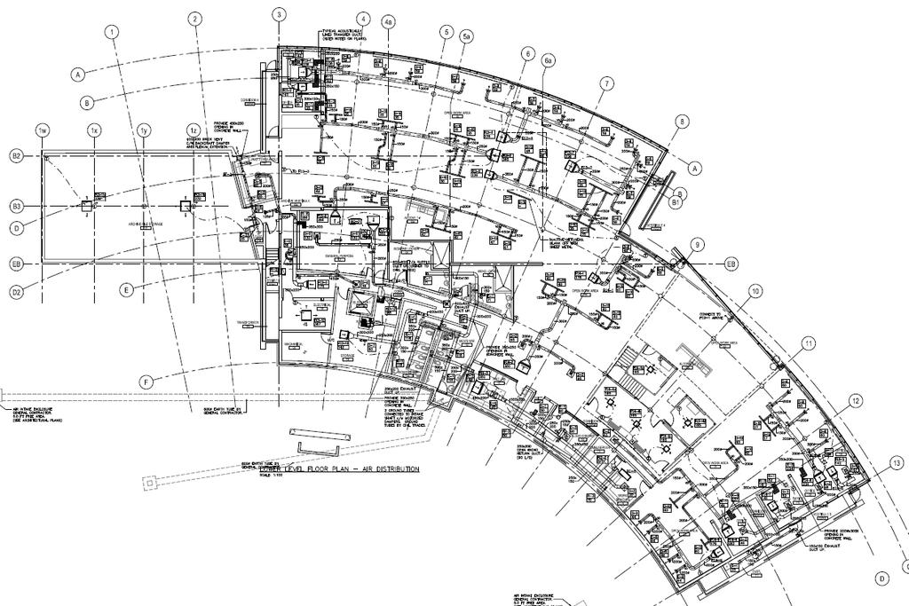
101 Ventilation System Design Concept ASHRAE 62.1: OUTSIDE AIR IS A FUNCTION OF AREA AND NUMBER OF PEOPLE IN SPACE DEMAND CONTROL VENTILATION OUTSIDE AIR (OA)- VENTILATION AIR AHU VFD ON SUPPLY FAN AHU IS USED FOR: Ventilating only Heating and cooling is done through dedicated zonal units SUPPLY AIR 100% OA STORAGE CLASSROOM 10% OA 40% OA H/C OFFICE 15% OA CO 2 O O CO 2 OFFICE 15% OA T MEETING 30% OA 101
102 Ventilation System Design 102
103 Ventilation System Design DOAS Unit 103

104 Ventilation System Design 104

105 Ventilation System Design 105

106 Ventilation System Design 106

107 Ventilation System Design 107

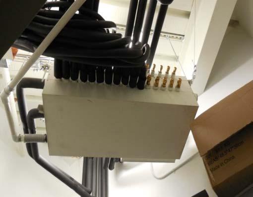
108 Variable Refrigerant Flow Condensing Units 108
109 Variable Refrigerant Flow Piping Schematic Heat rejected to Outside Ambient Low Temperature Renewable Heat Recovered from the Air Heat Pump Heat Pump Compressor Energy 1 kw Space Cooling Input 5kW Compressor Energy 1 kw High Temperature Heat Output to Space 5kW 109

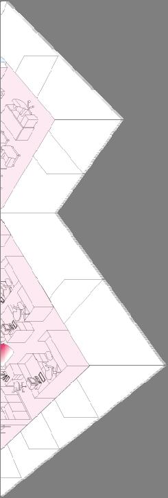
110 Variable Refrigerant Flow System Piping Layout 110

111 Variable Refrigerant Flow System Layout BC Controller Installation 111


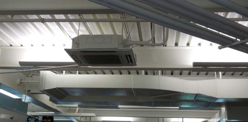
112 Variable Refrigerant Flow System Layout Ducted Indoor Units 112

113 Variable Refrigerant Flow System Layout Ducted Indoor Units 113

114 Variable Refrigerant Flow System Layout Cassette Style Units 114

115


116 116
117 Variable Refrigerant Flow System Layout Heat Recovery Potential WINTER SPRING, AUTUMN Domestic Hot Water Heating TANK SUMMER SPRING, AUTUMN Bathroom Shower Sanitary equipment 117
118 Variable Refrigerant Flow System Layout Heat Recovery Potential 65 (149F) Pump Closed loop circuit Treat the water with additive (160F) Water TANK T_water_outlet+5degC(9F) 75 (167F) R134 a 40 (104F) Comp. Bathroom Shower Sanitary equipment Booster Unit LEV 50 (122F) Up to 2.15 m3/h or 9.46 gpm CONDENSING Indoor unit Indoor unit Cooling UNIT R410 A BC controller Heat recovery
119 Variable Refrigerant Flow System Layout Heat Recovery Potential 119
120 Variable Refrigerant Flow System Layout Heat Recovery Potential 120

121 Variable Refrigerant Flow System Layout Heat Recovery Potential 121

122 Building Energy Analysis & Performance Additional Capital Cost 160,000 $ Savings per Year 33,726 $ Payback Period 4.74 Years The latest field measurements indicate annual energy usage 61.6 kwh/m2/year HVAC System = kwh/m2/yr 122
123 Questions/Conclusion 123
124 Evaluation and Certificate ASHRAE values your comments about this course. You will receive your Certificate of Attendance when you complete the online course evaluation at this URL: Access code: d4c2 Be sure to add your appropriate license numbers. If you have any questions about ASHRAE Certificates, please contact Kelly Arnold at If you have any questions about ASHRAE courses, please contact Martin Kraft, Managing Editor, at 124

125 ASHRAE Career Enhancement Curriculum Program Expand your knowledge of IAQ and Energy Savings Practices through a select series of ASHRAE Learning Institute courses Receive up-to-date instruction on new technology from industry experts Gain valuable HVAC knowledge Accelerate your career growth Receive a certificate for successful completion of the course series Visit to learn more.

126 ASHRAE Professional Certification Do you want to stand out from the crowd? Become ASHRAE certified. ASHRAE certification serves as a springboard for your continued professional development. Assure employers and clients that you have mastered the body of knowledge that subject matter experts have identified as reflecting best practices. Please visit the following URL to learn more about our programs: Building Energy Assessment Professional Building Energy Modeling Professional Commissioning Process Management Professional Healthcare Facility Design Professional High-Performance Building Design Professional Operations & Performance Management Professional 126
Variable Refrigeration Flow Systems Overview 10/11/2016
 Variable Refrigeration Flow Systems Overview 10/11/2016 Executed by Data Power Technology Illinois Aggressively, relentlessly anticipating and exceeding our customer s and client s expectations every day,
Efficiency Vermont The American Institute of Architects Continuing Education Systems (AIA/CES) AIA/CES AIA/CES
 AIA/CES AIA/CES") Efficiency Vermont is a Registered Provider with The American Institute of Architects Continuing Education Systems (AIA/CES). Credit(s) earned on completion of this program will be reported to AIA/CES
Efficiency Vermont is a Registered Provider with The American Institute of Architects Continuing Education Systems (AIA/CES). Credit(s) earned on completion of this program will be reported to AIA/CES
Variable refrigerant flow (VRF) systems
 systems") SBS5311 HVACR II http://ibse.hk/sbs5311/ Variable refrigerant flow (VRF) systems Ir. Dr. Sam C. M. Hui Faculty of Science and Technology E-mail: cmhui@vtc.edu.hk Oct 2017 Contents System Overview Components
SBS5311 HVACR II http://ibse.hk/sbs5311/ Variable refrigerant flow (VRF) systems Ir. Dr. Sam C. M. Hui Faculty of Science and Technology E-mail: cmhui@vtc.edu.hk Oct 2017 Contents System Overview Components
LG VRF Systems. Air Conditioning Technologies
 LG VRF Systems Air Conditioning Technologies 2018 ABOUT LG ABOUT LG VRF A Variable Flow (VRF) system is a single refrigerant circuit that connects many indoor units to one outdoor unit. VRF is a superior
The ultimate fresh air solution.
 Fresh Access The ultimate fresh air solution. Introducing Fresh Access TM. Expertly designed, our innovative energy recovery ventilator (ERV) unit, split dedicated outside air system (DOAS), and packaged
NET ENERGY WATER LOOPS A clear path to net zero energy buildings
 Presents NET ENERGY WATER LOOPS A clear path to net zero energy buildings Alan Niles WaterFurnace International This ASHRAE Distinguished Lecturer is brought to you by the Society Chapter Technology Transfer
Technical Development Program. COMMERCIAL HVAC PACKAGED EQUIPMENT Split Systems PRESENTED BY: Ray Chow Sigler
 Technical Development Program COMMERCIAL HVAC PACKAGED EQUIPMENT Split Systems PRESENTED BY: Ray Chow Sigler Menu Section 1 Section 2 Section 3 Section 4 Section 5 Section 6 Section 7 Introduction System
Technical Criteria for District Energy Ready Buildings Master Requirement ENG 108 Building Department: ,
 Purpose 355 West Queens Road Technical Criteria for District Energy Ready Buildings Master Requirement ENG 108 Building Department: 604-990-2480, building@dnv.org The purpose of this document is to provide
Product Line Introduction. Karl Zhang Technical support engineer
 Product Line Introduction Karl Zhang Technical support engineer Air Conditioning Solutions Heating & Hot Water Solutions Control Solutions Air Conditioning Solutions Residential Application Commercial
Submitted to Reference Approval Construction Unit Designation Schedule #
 Page 1of5 Job Name Location Purchaser Engineer Submitted to Reference Approval Construction Unit Designation Schedule # System Performance Modules Connected US Ton (nominal) Capacity (Btu/h) System Specifications
2. CURRICULUM. Sl. No.
 . CURRICULUM Sl. No. Code Title No. of Lecture Hours 1 RAC 001 Fundamentals of Refrigeration and Air 60 conditioning RAC 00 Psychrometry, Heat load Estimation for 70 Air conditioning and Refrigeration
Heat pump and energy recovery systems
 SBS5311 HVACR II http://ibse.hk/sbs5311/ Heat pump and energy recovery systems Ir. Dr. Sam C. M. Hui Faculty of Science and Technology E-mail: cmhui@vtc.edu.hk Oct 2017 Contents Basic concepts Air-to-air
Submittal Data Performance Data Electrical Data
 ERMS Series Submittal Data Submittal Data Unit Designation: Job name: Architect: Engineer: Contractor: Performance Data Revision: 07/01/11 Cooling Capacity: EER: Heating Capacity: COP: Ambient Air Temp:
CHAPTER 4. HVAC DELIVERY SYSTEMS
 CHAPTER 4. HVAC DELIVERY SYSTEMS 4.1 Introduction 4.2 Centralized System versus Individual System 4.3 Heat Transfer Fluids 4.4 CAV versus VAV Systems 4.5 Common Systems for Heating and Cooling 4.6 Economizer
Humidity Control Design Tips. R. Mark Nunnelly, PE, CxA, LEED AP President
 Humidity Control Design Tips R. Mark Nunnelly, PE, CxA, LEED AP President AIA Quality Assurance The Building Commissioning Association is a Registered Provider with The American Institute of Architects
ASHRAE Region VI CRC Track III: Session 3 Ventilation Energy Recovery. Steven T. Taylor, PE Principal Taylor Engineering
 ASHRAE Region VI CRC Track III: Session 3 Ventilation Energy Recovery Steven T. Taylor, PE Principal Taylor Engineering This program is registered with the AIA/CES for continuing professional education.
Designing Energy Efficient Outdoor Air Systems
 Designing Energy Efficient Outdoor Air Systems Joseph Thorndal Applied Products Sales Manager Greenheck, Schofield, Wisconsin 1 Joseph Thorndal BS Industrial Engineering North Dakota State University Work
IAQ VENTILATORS. FRESH AIR REQUIREMENTS. Applications ASHRAE 62.1, 90.1 & School / university / day care.
 FRESH AIR REQUIREMENTS ASHRAE 62.1, 90.1 & 189.1 Applications Health / beauty / spa Pet shop / veterinary clinic ice / conference room School / university / day care Medical / pharmaceutical Museum / library
Design Considerations For Dedicated OA Systems BY HUGH CROWTHER, P.ENG, MEMBER ASHRAE; YI TENG MA, ASSOCIATE MEMBER ASHRAE
 ASHRAE www.ashrae.org. Used with permission from ASHRAE Journal. This article may not be copied nor distributed in either paper or digital form without ASHRAE s permission. For more information about ASHRAE,
Submitted to Reference Approval Construction Unit Designation Schedule #
 Page 1of Job Name Location Purchaser Engineer Submitted to Reference Approval Construction Unit Designation Schedule # System Performance Power Indoor Units Modules Connected US Ton (nominal) Capacity
Energy Use in Refrigeration Systems
 2012 Rocky Mountain ASHRAE Technical Conference Energy Use in Refrigeration Systems PRESENTED BY: Scott Martin, PE, LEED AP BD+C Objectives Understand mechanical refrigeration terms Describe how heat is
CARRIER edesign SUITE NEWS. Modeling 100% OA Constant Volume Air Systems. Volume 6, Issue 1. Page 1 Modeling 100% OA Constant Volume Air Systems
 Volume 6, Issue 1 CARRIER edesign SUITE NEWS Modeling 100% OA Constant Volume Air Systems This article provides an overview of how to model a stand-alone constant air volume (CAV) 100% OA system in HAP.
UNIVERSITY OF MISSOURI Heating Ventilating and Air-Conditioning (HVAC) 2016 Q1
 2016 Q1") GENERAL: This section provides general standards for overall sizing and design of Heating, Ventilating, and Air Conditioning (HVAC) systems. Other sections contain specific standards for each system per
GENERAL: This section provides general standards for overall sizing and design of Heating, Ventilating, and Air Conditioning (HVAC) systems. Other sections contain specific standards for each system per
Daikin Blueprint: Delivering Hot Water with a Chiller
 Daikin Blueprint: Delivering Hot Water with a Chiller Analyzing the design of heat recovery on air-cooled chillers and the effect it has on building energy consumption By Paul Crisman Daikin Chiller Applications
ASHRAE WILL GIVE YOU THE WORLD. This ASHRAE Distinguished Lecturer is brought to you by the Society Chapter Technology Transfer Committee
 ASHRAE WILL GIVE YOU THE WORLD This ASHRAE Distinguished Lecturer is brought to you by the Society Chapter Technology Transfer Committee Complete the Distinguished Lecturer Event Summary Critique CTTC
HONORABLE MENTION: COMMERCIAL BUILDINGS, EXISTING
 ASHRAE s BEST This article was published in ASHRAE Journal, November 2010. Copyright 2010 American Society of Heating, Refrigerating and -Conditioning Engineers, Inc. Reprinted here by permission from
Energy Savings Potential of Passive Chilled Beam System as a Retrofit Option for Commercial Buildings in Different Climates
 Purdue University Purdue e-pubs International High Performance Buildings Conference School of Mechanical Engineering 2014 Energy Savings Potential of Passive Chilled Beam System as a Retrofit Option for
NON-REVERSING, 100% OUTSIDE AIR HEAT PUMP FOR HEATING AND COOLING
 NON-REVERSING, 100% OUTSIDE AIR HEAT PUMP FOR HEATING AND COOLING Danny Hall, National Sales Manager, Desert Aire Corp., Milwaukee, WI USA Traditionally, a heat pump has relied on a reversing valve system
Selection of air conditioning systems
 Selection of air conditioning systems Prof. M. Ramgopal Department of Mechanical Engineering IIT Kharagpur Objectives 1. List the criteria used in the selection of air conditioning systems 2. List typical
APPLICATION GUIDE BEAMS
 BEAMS There is an increasing need for energy efficient air conditioning systems as energy codes become more stringent. Chilled beam systems are one such alternate to traditional all air conditioning systems.
COLD STORAGE WAREHOUSE, USING DIRECT EXPANSION AMMONIA REFRIGERANT Ray Clarke ISECO Consulting Services Pty Ltd
 COLD STORAGE WAREHOUSE, USING DIRECT EXPANSION AMMONIA REFRIGERANT Ray Clarke ISECO Consulting Services Pty Ltd Abstract This paper presents the design approach adopted for the expansion of a large existing
Appendix 13. Categories of Cooling and Heating systems
 EcoShopping - Energy efficient & Cost competitive retrofitting solutions for Shopping buildings Co-funded by the European Commission within the 7 th Framework Programme. Grant Agreement no: 609180. 2013-09-01
Bill McCullough. Director ERV Products. Dallas, TX
 Bill McCullough Director ERV Products Dallas, TX TOPICS 1. ERV Definition & Benefit 2. Indoor Air Quality 3. Energy Efficiency 4. ERV Technology & Operation 5. Stand-Alone ERVs 6. Compact ERVs What is
FACT SHEET 9 Large Air-Conditioning (air-to-air)
") FACT SHEET 9 Large Air-Conditioning (air-to-air) UNEP Ozone Secretariat UNEP Ozone Secretariat Background Workshop Material for on HFC HFC Workshop, management: 205 technical issues Bangkok, 20 and 2 April
FACT SHEET 9 Large Air-Conditioning (air-to-air) UNEP Ozone Secretariat UNEP Ozone Secretariat Background Workshop Material for on HFC HFC Workshop, management: 205 technical issues Bangkok, 20 and 2 April
FACT SHEET 9 Large Air-Conditioning (air-to-air)
") UNEP Ozone Secretariat UNEP Ozone Secretariat Background Material on HFC Management Fact Sheets on HFCs and Low GWP Alternatives October 205 FACT SHEET 9 Large Air-Conditioning (air-to-air). Description
UNEP Ozone Secretariat UNEP Ozone Secretariat Background Material on HFC Management Fact Sheets on HFCs and Low GWP Alternatives October 205 FACT SHEET 9 Large Air-Conditioning (air-to-air). Description
Variable Refrigerant Flow (VRF) Systems
 Systems") Variable Refrigerant Flow (VRF) Systems Flexible Solutions for Comfort Carrier Corporation Syracuse, New York January 2013 TABLE OF CONTENTS INTRODUCTION... 2 VRF TECHNOLOGY... 2 ADVANTAGES OF A VRF SYSTEM...
Variable Refrigerant Flow (VRF) Systems Flexible Solutions for Comfort Carrier Corporation Syracuse, New York January 2013 TABLE OF CONTENTS INTRODUCTION... 2 VRF TECHNOLOGY... 2 ADVANTAGES OF A VRF SYSTEM...
COMMERCIAL HVAC SYSTEMS Water Source Heat Pump Systems
 COMMERCIAL HVAC SYSTEMS Water Source Heat Pump Systems Technical Development Program Technical Development Programs (TDP) are modules of technical training on HVAC theory, system design, equipment selection
Method to test HVAC equipment at part load conditions
 IPLV Method to test HVAC equipment at part load conditions For water cooled chillers: 100% load ( % hrs) + 75% ( Hrs ) + 50% ( Hrs ) + 25% ( Hrs ) = IPLV value Manufacturer can favor this number by tweaking
ENGINEERING. Edition No. 13 October 2002
 Edition No. 13 October 2002 ENGINEERING S Y S T E M S O L U T I O N S W e at McQuay are very proud of our tradition of producing industry leading water source heat pumps. Our heritage stretches back more
CARRIER edesign SUITE NEWS. Interpreting High (Low) Peak Design Airflow Sizing Results for HVAC. Equipment Selection.
 Peak Design Airflow Sizing Results for HVAC. Equipment Selection.") Volume 5, Issue 1 CARRIER edesign SUITE NEWS Interpreting High (Low) Peak Design Airflow Sizing Results for HVAC Equipment Selection A design challenge sometimes occurs when computing design loads using
Volume 5, Issue 1 CARRIER edesign SUITE NEWS Interpreting High (Low) Peak Design Airflow Sizing Results for HVAC Equipment Selection A design challenge sometimes occurs when computing design loads using
Multiple split-system air-conditioners and air-to-air heat pumps Testing and rating for performance
 DRAFT INTERNATIONAL STANDARD ISO/DIS 15042 ISO/TC 86/SC 6 Voting begins on: 2005-07-11 Secretariat: ANSI Voting terminates on: 2005-12-12 INTERNATIONAL ORGANIZATION FOR STANDARDIZATION МЕЖДУНАРОДНАЯ ОРГАНИЗАЦИЯ
Performance Rating of Variable Refrigerant Flow (VRF) Multi-split Air-conditioning and Heat Pump Equipment
 Multi-split Air-conditioning and Heat Pump Equipment") AHRI Standard 1230 with Addendum 1 2014 Standard for Performance Rating of Variable Refrigerant Flow (VRF) Multi-split Air-conditioning and Heat Pump Equipment AHRI STANDARD 1230-2014 WITH ADDENDUM 1,
AHRI Standard 1230 with Addendum 1 2014 Standard for Performance Rating of Variable Refrigerant Flow (VRF) Multi-split Air-conditioning and Heat Pump Equipment AHRI STANDARD 1230-2014 WITH ADDENDUM 1,
Displacement Ventilation
 Displacement Ventilation Displacement Ventilation Displacement Ventilation vs. Dilution Ventilation Characteristics Design Considerations Layout and Selection Product Overview Casino Case Study Dilution
Application of Air Source Variable Refrigerant Flow in Cold Climates
 PREPARED BY Seventhwave with the assistance of Daikin North America, LLC Masters Building Solutions Application of Air Source Variable Refrigerant Flow in Cold Climates A White Paper March 2015 275-1
General HVAC Recommendations
 General HVAC Recommendations DESIGN GUIDELINES FOR ENERGY EFFICIENT HVAC SYSTEMS Thank you for your interest in energy efficiency! Energy efficient heating, ventilation, and air conditioning (HVAC) equipment
Leverage Building Energy Diversity in High Efficiency HVAC Design
 Leverage Building Energy Diversity in High Efficiency HVAC Design Water-source heat pumps prove to be more energy-efficient than alternative systems for commercial buildings. A version of this article
Energy-Efficient Makeup Air Units BY HUGH CROWTHER, P.ENG., MEMBER ASHRAE
 This article was published in ASHRAE Journal, March 20145 Copyright 2015 ASHRAE. Posted at www.ashrae.org. This article may not be copied and/or distributed electronically or in paper form without permission
HVAC 101. H V A C S y s t e m s
 H V A C 1 0 1 S y s t e m s Introduction & Overview Should you care? Mechanical System Types Components & operation Popular Application Key Issues and Design Considerations System Comparisons First Cost
NFZP Variable Refrigerant Flow Guide Specification
 PART 1 - GENERAL 1.01 SECTION INCLUDES SECTION 23 81 29 VARIABLE REFRIGERANT FLOW HVAC SYSTEM A. (VRF) HVAC system includes: 1. Outdoor/Condensing unit(s): a. Size Range: 14 Tons Nominal b. YANMAR VRF
Green Maintenance Needed to Keep HVAC Systems Green
 Green Maintenance Needed to Keep HVAC Systems Green Robert G. (Bob) Baker BBJ Consulting Service 235 Apollo Beach Blvd. #157 Apollo Beach, Florida bbaker@bbjconsultingservice.com ASHRAE is a Registered
SYNOPSIS. Part-Load Control Strategies for Packaged Rooftop Units. In this issue... Bin Hour Profile Charlotte, NC
 VOLUME ONE NUMBER THREE SYNOPSIS A N H V A C N E W S L E T T E R F O R B U I L D I N G O W N E R S A N D M A N A G E R S In this issue... Part-Load Strategies Why they re important.......... 1 What Things
recooler HP EQKR HEAT PUMP
 AIR COMFORT AIR TREATMENT 9566 GB 2016.03.17 recooler HP EQKR HEAT PUMP» TECHNICAL CATALOGUE 2 ReCooler HP EQKR Technical Catalogue Content ReCOOLER HP EQKR HEAT PUMP 3 product presentation. 3 applications.
Chiller Vs VRF Comparison
 Chiller Vs VRF Comparison At the time of designing a HVAC project, it is required to understand the project requirements, type of application, duty conditions and compliance to relevant standards. In order
Munters Heat Exchangers
 Munters Heat Exchangers Brad Perdew Applications Engineer 8/27/12 DOAS Configurations Cheryl Hughes Regional Sales Manager October 11, 2016 cheryl.hughes@munters.com Munters DOAS Configurations Presentation
DEHUMIDIFICATION: Ice Arena Application & Product Guide. Design, construct and operate to control indoor humidity in ice rinks
 DEHUMIDIFICATION: Ice Arena Application & Product Guide Design, construct and operate to control indoor humidity in ice rinks Munters is the world leader in dehumidification Munters is the largest manufacturer
High Efficiency Heating and Cooling Systems for Community Colleges Kirk Mescher, PE, LEED AP Principal ICCCFO
 High Efficiency Heating and Cooling Systems for Community Colleges Kirk Mescher, PE, LEED AP Principal ICCCFO 2012 1 Learning Objectives for this Session Get acquainted with typical systems used in the
Air Cooled Packaged Systems AIRAH Back to Basics
 Air Cooled Packaged Systems AIRAH Back to Basics What s changed? New Refrigerants R410a MEPS EER / AEER / SEER Manufacturing Technologies Research, Development and Testing New technologies, controls, reliability
CTI Sponsored Educational Program
 Presented By: Kent Martens SPX Cooling Technologies, Inc. Slide No.: 1 CTI Mission Statement To advocate and promote the use of environmentally responsible Evaporative Heat Transfer Systems (EHTS) for
Update Dedicated Heat Recovery Chiller Technology. Don Frye. Gulf South
 3/5/2018 1 Update Dedicated Heat Recovery Chiller Technology Don Frye Gulf South Good design is an intentional act Begin with the end in mind Basic Bldg Tenants IAQ (low VOC & CO 2 ) Controlled Temp &
BOOK 1 OVERVIEW RD2XRT INSTALLATION AND OPERATION MANUAL. Table of Contents ABOUT BOOK 1:
 4510 Helgesen Drive, Madison, WI, 53718 608.221.4499, 800.627.4499, Fax: 608.221.2824 support@renewaire.com www.renewaire.com RD2XRT INSTALLATION AND OPERATION MANUAL BOOK 1 OVERVIEW ABOUT BOOK 1: This
Prescriptions for Critical Healthcare Cx. John D. Villani, P.E. Associate Grumman/Butkus Associates
 Prescriptions for Critical Healthcare Cx John D. Villani, P.E. Associate Grumman/Butkus Associates AIA Quality Assurance Learning Objectives 1. Medical Industry Changes and how they impact Design, Construction,
Modular Active. Chilled. Beams
 Modular Active Chilled Beams How Twa MAC Beams Work Primary air (100% outside air) is dehumidified to between 50-57 F dew point and is used to: control the latent requirements of the space, provide fresh
BOOK 1 OVERVIEW RD2XIN INSTALLATION AND OPERATION MANUAL. Table of Contents ABOUT BOOK 1:
 4510 Helgesen Drive, Madison, WI, 53718 608.221.4499, 800.627.4499, Fax: 608.221.2824 support@renewaire.com www.renewaire.com RD2XIN INSTALLATION AND OPERATION MANUAL BOOK 1 OVERVIEW ABOUT BOOK 1: This
Energy Recovery with Cooling and Heating Model ERCH
 Energy Recovery with Cooling and Heating Model ERCH 100% Outdoor Air System Dedicated Outdoor Air System 1,000-10,000 cfm 1.75 in. wg External Static Pressure Indirect Gas, Hot Water, Electric Heating,
SECTION SEQUENCE OF OPERATIONS FOR HVAC CONTROLS
 SECTION 23 09 93 SEQUENCE OF OPERATIONS FOR HVAC CONTROLS PART 1 - GENERAL 1.1 SUMMARY A. This Section includes control sequences for HVAC systems, subsystems, and equipment. B. See Division 23 Section
Senior Thesis Centre Community Hospital East Wing Addition - Proposal Keith Beidel Mechanical Option 12/05/02 1
 Table of Contents Page Number(s) Executive Summary 2 Project Background 3 Proposed Depth Alternatives 4 Proposed Depth Redesign 5-7 Justification of Proposed Depth Redesign 8 Proposed Breath Redesign 9
terminal units only provide sensible cooling, a separate dehumidification system is usually needed.
 providing insights for today s hvac system designer Engineers Newsletter volume 44 3 Dual-Temperature Chiller Plants This Engineers Newsletter describes several dual-temperature configurations that can
New and Emerging HVAC Technologies. Rod Rhoads, GDS Associates Dave McCullaugh, Mitsubishi Electric Trane HVAC US Dave Binz, Cambridge Engineering
 New and Emerging HVAC Technologies Rod Rhoads, GDS Associates Dave McCullaugh, Mitsubishi Electric Trane HVAC US Dave Binz, Cambridge Engineering Rod Rhoads, Leidos Custom for non standard projects» Custom
Mechanical System Redesign. Dedicated Outdoor Air System. Design Criteria
 Mechanical System Redesign Dedicated Outdoor Air System Design Criteria The outdoor air conditions used were for Philadelphia, Pennsylvania IAP at a 0.4% occurrence. The supply air conditions were developed
KE2 EvaporatorEfficiency Theory of Operation
 Theory T.1.1 June 011 TM thermsolutions ENTER BACK KE Therm Solutions, Advanced Energy Saving Technology for Commercial Refrigeration and AC Systems Page Table of Contents Basic Refrigeration System Evaporator
By Thomas H. Durkin, P.E., Member ASHRAE, and James B. (Burt) Rishel, P.E., Fellow/Life Member ASHRAE
 Rishel, P.E., Fellow/Life Member ASHRAE") By Thomas H. Durkin, P.E., Member ASHRAE, and James B. (Burt) Rishel, P.E., Fellow/Life Member ASHRAE T he advent of the small scroll or screw chiller, capable of producing condenser water as high as 140
By Thomas H. Durkin, P.E., Member ASHRAE, and James B. (Burt) Rishel, P.E., Fellow/Life Member ASHRAE T he advent of the small scroll or screw chiller, capable of producing condenser water as high as 140
Session: HVAC 101 HVAC 101. Steve Sain Sain Engineering Associates, Inc. August 9, Rhode Island Convention Center Providence, Rhode Island
 Session: HVAC 101 HVAC 101 Steve Sain Sain Engineering Associates, Inc. August 9, 2016 Rhode Island Convention Center Providence, Rhode Island Why? 2 Acknowledgements 3 Disclaimer I m gonna shoot down
Product Release Summary
 Product Release Summary 48/50HC with System March 2012 TC Benefits of EnergyX System Why Energy Recovery 1. Code requirements: ASHRAE 90.1-2004: Energy Recovery is required when design supply air capacity
Small Commercial Business Energy Audits. Recognizing and addressing the special requirements of the small business market segment.
 Small Commercial Business Energy Audits Recognizing and addressing the special requirements of the small business market segment. Class 7 Class 7: Refrigeration Fundamentals The Vapor-compression cycle
Trane Engineers Newsletter Live
 Trane Engineers Newsletter Live Presenters: John Murphy, Dustin Meredith and Jeanne Harshaw (host) Trane program number: APP-CMC059-EN Agenda Trane Engineers Newsletter Live Series Abstract The Air Movement
Heat Recovery Units. Heat Recovery 1
 Heat Recovery Units Heat Recovery 1 Heat Recovery Unit Why? A heat recovery unit (HRU) can help make mechanical ventilation more cost effective by reclaiming energy from exhaust airflows. HRUs use air-to-air
Energy Recovery Ventilators
 Energy Recovery Ventilators Models ERM, MiniVent, ERV and ERVe Untempered Preconditioners September 2016 Energy Recovery Ventilators Greenheck offers a complete line of energy recovery ventilators to reduce
H O B O K E N R E S I D E N T I A L
 Proposal 1: Open Loop Geothermal for Water Source Packaged Terminal Heat Pumps and Heat Recovery Ventilation and Humidifier Heating and Cooling System Schematic Ventilation Schematic Proposal 1 System
Inverter Hot Water Heat Pumps
 Inverter Hot Water Heat Pumps Inverter Hot Water Heat Pumps Hot Water Heat Pump Systems Underfloor Heating Swimming Pools Spa Pools Sanitary Water Pre-heating Hydroponics Aquaculture Water Chilling Hot
Applying VRF? Don t Overlook Standard 15
 This article was published in ASHRAE Journal, July 2012. Copyright 2012 ASHRAE. Posted at www.ashrae.org. This article may not be copied and/or distributed electronically or in paper form without permission
INTRODUCTION TO: ASHRAE STANDARD 90.1, HVAC System Requirements for Reducing Energy Consumption in Commercial Buildings
 INTRODUCTION TO: ASHRAE STANDARD 90.1, 2013 HVAC System Requirements for Reducing Energy Consumption in Commercial Buildings Rocky Mountain ASHRAE Technical Conference, April 29, 2016 SEAN BEILMAN, P.E.,
Application of two hybrid control methods of expansion valves and vapor injected compression to heat pumps
 AM-4249223-1 - Application of two hybrid control methods of expansion valves and vapor injected compression to heat pumps Christian K. Bach, Graduate Student, Eckhard A. Groll, Reilly Professor, James
Cultivator & Hybrid Cultivator
 Cultivator & Hybrid Cultivator Precision Temperature & Humidity Packaged Unit INTRODUCTION The Cultivator Series package unit is the industry s MOST ENERGY EFFICIENT and HIGHEST capacity dehumidifier on
HVAC DISTRIBUTION and DELIVERY SYSTEMS
 HVAC DISTRIBUTION and DELIVERY SYSTEMS (Part 1) Ball State Architecture ENVIRONMENTAL SYSTEMS 2 Grondzik 1 REMINDER HVAC = Heating, Ventilating, Air-Conditioning The AC part of HVAC implies a system that
2009 IECC Commercial Mechanical Requirements
 BUILDING ENERGY CODES UNIVERSITY 2009 IECC Commercial Mechanical Requirements Ken Baker PNNL-SA-66171 Learning(Objec-ves(( ( 1. Find(minimum(equipment(efficiency(requirements( and(recite(at(least(3(common(terms(for(measuring(
Applying VRF? Don t Overlook Standard 15
 This article was published in ASHRAE Journal, July 2012. Copyright 2012 ASHRAE. Posted at www.ashrae.org. This article may not be copied and/or distributed electronically or in paper form without permission
August 15, 2013 Page 1 of 19
 Section C401 Application Compliance with C402, C403, C404 and C405 AND (either C406.2, C406.3 or C406.4) Compliance with C402, C403, C404 or C405 Section C402 Building Envelope (Climate Zone 5A) Space-Conditioning
AHRI 920 Performance Rating and Comparisons of DX-DOAS Unit Efficiency
 Application Note 24 AHRI 920 Performance Rating and Comparisons I NTRODUCTION In 2015, the Air-Conditioning, Heating, and Refrigeration Institute (AHRI) introduced a performance rating for dedicated outside
AIR-CONDITIONING SYSTEMS AND APPLICATIONS. Abdullah Nuhait Ph D. King Saud University
 AIR-CONDITIONING SYSTEMS AND APPLICATIONS Abdullah Nuhait Ph D. King Saud University AIR-CONDITIONING SYSTEMS Earliest air conditioning system used only for heating (winter) Provided heated air for comfort
TEST REPORT #14. System Drop-In Test of Refrigerant Blend ARM-42a in an Air-Cooled Screw Chiller
 Air-Conditioning, Heating, and Refrigeration Institute (AHRI) Low-GWP Alternative Refrigerants Evaluation Program (Low-GWP AREP) TEST REPORT #14 System Drop-In Test of Refrigerant Blend ARM-42a in an Air-Cooled
MT. AIRY MIDDLE SCHOOL CARROLL COUNTY PUBLIC SCHOOLS
 CARROLL COUNTY PUBLIC SCHOOLS LIFE CYCLE COST ANALYSIS SUMMARY DGS PROCEDURES FOR THE IMPLEMENTATION OF LIFE CYCLE COST ANALYSIS AND ENERGY CONSERVATION OCTOBER, 2010 G.A.I.#09090 GIPE ASSOCIATES, INC.
SPECIFICATION GUIDE FLEXAIR. Possibility to add auxiliary heaters: Gas, Electrical Heater, Hot Water Coil Possibility to add Heat Recovery Module
 SPECIFICATION GUIDE FLEXAIR Air-cooled packaged Rooftop unit Cooling only or Heat Pump Nominal cooling capacity: 85 to 234 kw Nominal heating capacity: 83 to 226 kw Possibility to add auxiliary heaters:
RT-OA TM Rooftop Outdoor-Air (DOAS)
") RT-OA TM Rooftop Outdoor-Air (DOAS) A/C s & HEAT PUMPS Dedicated Outside-Air System (DOAS) Solutions Office Buildings, Schools, Hospitals, Restaurants, Gyms & Fitness Centers, Hotels, Retail Stores...!
RT-OA TM Rooftop Outdoor-Air (DOAS) A/C s & HEAT PUMPS Dedicated Outside-Air System (DOAS) Solutions Office Buildings, Schools, Hospitals, Restaurants, Gyms & Fitness Centers, Hotels, Retail Stores...!
VRV The total solution. Integrated Climate Control
 VRV The total solution Integrated Climate Control Total Solution Concept The Daikin VRV Total Solution provides a single point of contact for the design and maintenance of your integrated climate control
MiniCore Ventilator (500, 1000) Series Engineering Guide
 Series Engineering Guide") MiniCore Ventilator (500, 1000) Series Engineering Guide November 2017 V1.0 Johnson Controls, Inc. All rights reserved. TABLE OF CONTENTS Page Functionality and Benefits... 1 Unit Overview... 3 MiniCore
MiniCore Ventilator (500, 1000) Series Engineering Guide November 2017 V1.0 Johnson Controls, Inc. All rights reserved. TABLE OF CONTENTS Page Functionality and Benefits... 1 Unit Overview... 3 MiniCore
Commercial Buildings Chilled water systems efficiency By Jens Nørgaard, Senior Application Manager, Grundfos, Denmark
 Commercial Buildings Chilled water systems efficiency By Jens Nørgaard, Senior Application Manager, Grundfos, Denmark Introduction: Energy use is the single largest operating expense in commercial office
WORKSHOP VENTILATION- PSYCHROMETRICS-AHU
 Alkis Triantafyllopoulos Mechanical Engineer Member TEE, MASHRAE a.trianta@gmail.com WORKSHOP VENTILATION- PSYCHROMETRICS-AHU Based on ASHRAE 62 Purpose Set minimum Outdoor Air ventilation Rates Air Quality
Increase your flexibility.
 DVM CHILLER Increase your flexibility. Get the best of two worlds. This easy to expand, modular unit combines the benefits of VRF and Chiller systems. Product Registration Required Conditions Apply 2018
Thomas J Kelly. Fundamentals of Refrigeration. Sr. Engineering Instructor Carrier Corporation. August 20, Page number: 1.
 Thomas J Kelly Sr. Engineering Instructor Carrier Corporation August 20, 2003 1 SESSION OBJECTIVES At the conclusion of this session you should be able to: 1. Describe the basics principles of refrigeration
Heat Recovery Ventilator Model PVe Light Industrial Commercial Institutional
 Heat Recovery Ventilator Model PVe Light Industrial Commercial Institutional 1,000-6,000 cfm 2.0 in. wg External Static Pressure Aluminum Plate Heat Exchanger April 2017 Heat Recovery Ventilators Greenheck