DC 60 & DM 60 displays
|
|
|
- Eleanor George
- 5 years ago
- Views:
Transcription


")

1 USER MANUAL DC 60 & DM 60 displays BALTIC FLEXAIR ENERGY AIRCOOLAIR COMPACTAIR FLATAIR (& Inverter) AQUALEAN DC60-DM60-IOM-1310-E
2
3 Summaries 1 Display DC Introduction Temperature measurement Quick Action Presentation Use DC60 set in Light mode DC60 set in Full mode Setting Value Activation level Display DM Quick Action Functionality of the DM Organizational screens Alarm List by Code DC60, Installation 4.1 Connection Ferrites Protection of Displays Temperature Sensor Configuration Initialization DM60, Installation 5.1 Connection Connection on the splitter DT Ferrites Protection of Displays Configuration DC60-DM60 Communication Master/Slaves 6.1 Connection DC60-DM60-ROOFTOP-IOM-1310-E - 1 -
4 1 Display DC Introduction The display DC60 is customized for the user. It allows an overview of the operation of the Unit and allows access to some parameters. Depending on the setting in the Climatic, two display configurations are possible: Mode Light Mode Full The 'DC60' is designed to be remotely connected of the Unit. The 'DC60' is equipped with a temperature sensor. The temperature sensor allows the acquisition of room temperature to control. 1.2 Temperature measurement All Lennox Unit comes with a temperature sensor; it must be placed in the conditioned area. But if the 'DC60' is placed in the area conditioned by the Unit, it is possible, in this case, to use the temperature measurement of the 'DC60'. DC60-DM60-ROOFTOP-IOM-1310-E - 2 -

5 1.3 Quick Action How to See the Operation of the Unit 4? Only if several units are connected to the DC60. Turn the knob to have the text Unit. Press the knob to switch in 'Set' mode. Turn the knob to select number 4. Press the knob to confirm your choice How to Start all Units connected at this DC60? Press the button a few seconds. The units can not be powered On/Off by the DC60 if the service display DS60 is connected. DC60-DM60-ROOFTOP-IOM-1310-E - 3 -
6 1.3.3 How to Start Unit 4? Only if several units are connected to the DC60. Select the Unit 4 (see: How to See the Operation of the Unit 4?) Turn the knob to have the text I-O. Press the knob to switch in 'Set' mode. Turn the knob to select number 1 (1 for On, 0 for Off ). Press the knob to confirm your choice The units can not be powered On/Off by the DC60 if the service display DS60 is connected How to See the Value of the Current Setpoint Temperature? Turn the knob to have the text Set. The value displayed is the temperature setpoint. DC60-DM60-ROOFTOP-IOM-1310-E - 4 -


7 1.3.5 How to Modify the Value of the Current Setpoint Temperature? Turn the knob to have the text Set. Press the knob to switch in 'Set' mode. Turn the knob to change the value. Press the knob to confirm your choice DC60-DM60-ROOFTOP-IOM-1310-E - 5 -

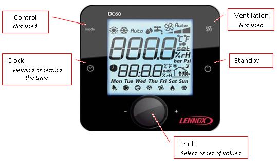
8 1.4 Presentation Showing Buttons DC60-DM60-ROOFTOP-IOM-1310-E - 6 -
 or automatic (Auto). Minimum speed Median speed Maximum speed Automatic Speed 1.5.")

9 1.5 Use Control operating mode. Only for Flatair and Aqualean ranges. Press until the desired operating mode is displayed. Heating mode Cooling mode Automatic mode Fan Speed Management. Only for Flatair and Aqualean ranges. Press to select the desired speed (min, med, max) or automatic (Auto). Minimum speed Median speed Maximum speed Automatic Speed On/Off unit By supporting a few seconds, the button you can activate or not (On/Off) the Unit connected. If the symbol completed by the time is displayed, the Unit is stopped and the 'DC60' in sleep mode. To restart the unit, press the button a few seconds If the DC60 is used with the Master/Slaves bus in this case, the 'Off' phase, stops all Rooftop connected on the Bus, 'On' phase restarts all. DC60-DM60-ROOFTOP-IOM-1310-E - 7 -

10 1.5.4 Setting time At initialization of the 'DC60', the Climatic 60 are synchronized time and day of week with the clock 'DC60'. To view the clock, briefly, press the button To set the clock press the button a few seconds The hour value, flashes. Turn the knob to adjust the desired value. Press the knob to select your choice. Then the minute value, flashes. Turn the knob to adjust the desired value. Press the knob to select your choice. Monday Tuesday Wednesday Thursday Friday Saturday Sunday Then the weekday value, flashes. Turn the knob to adjust the desired value. Press the knob to select your choice. After a few seconds 'DC60' communicates the new time to the Climatic Information available By rotating the knob you can view or modify the following values: 1.6 DC60 set in Light mode * : Unit Index selected by the DC60 : Volatile temperature set point current mode ( C) : : Indoor (Room) temperature ( C) : Alarms code * : Available if the option is enabled. : Adjustable with DC Unit selected If the DC60 is used with the Master/Slaves bus this item can select or know the Unit Index selected by the 'DC60'. DC60-DM60-ROOFTOP-IOM-1310-E - 8 -
11 1.6.2 Volatile Temperature set point This item allows you to view and/or modify the control temperature required for the Unit selected. If this point is changed, this value is used until the scheduling changes mode (Day, Day I, Day II, Night, BMS). At each change of the mode, the Climatic 60 sets the value of this set point on the preset value in the mode concerned Alarms code This item allows you to view the code of different active alarms on the Unit. If the Unit isn't in alarm, this item is to Indoor (Room) temperature This item indicates the measured air temperature in the room conditioning. The room temperature isn't available if the Climatic 60 is configured to supply control. 1.7 DC60 set in Full mode - : Unit Index selected by the DC60 - *: On/Off of the Unit selected. - : Predetermined temperature set point current mode ( C) - : Volatile temperature set point current mode ( C) - : Alarms code - * : Outdoor temperature ( C) - : Supply temperature ( C) - * : Indoor (Room) temperature ( C) - * : Indoor (Room) humidity (%hr) - * : Indoor (Room) Air quality (ppm) - * : Opening of fresh air damper (%) * : Available if the option is enabled. : Available if the level 2 is activated. : Adjustable with DC Unit connected This item can select or know the Unit Index selected by the 'DC60' On/Off, Power If the DC60 is used with the Master/Slaves bus this item allows you to view and/or change the status of starting or stopping of the Unit selected Volatile Temperature set point This item allows you to view and/or modify the control temperature required for the Unit selected. If this point is changed, this value is used until the scheduling changes mode (A, B, C, D, BMS). At each change of the mode, the Climatic 60 sets the value of this set point on the preset value in the mode concerned. DC60-DM60-ROOFTOP-IOM-1310-E - 9 -
12 1.7.4 Predetermined Temperature set point If level 2 is active, this item allows you to view and/or change the preset temperature control for the active mode Alarms code This item allows you to view the code of different active alarms on the Unit. If the Unit isn't in alarm, this item is to 0. By this item it's possible to reset the alarm activated. To do this set the value of the item to the value Outdoor temperature This item indicates the measure temperature of the air outside. The outside temperature isn't available for the WSHP range Supply temperature This item indicates the measure of outlet air temperature of the Unit Indoor (Room) temperature This item indicates the measured air temperature in the room conditioning. The room temperature isn't available if the Climatic 60 is configured to supply control Indoor (Room) relative humidity This item shows the measured relative humidity of the air in the room conditioning. The room humidity isn't available if the option of humidity management isn't set Measurement of CO² This item indicates the measured rate of CO² in conditioning room, in ppm. The measurement of CO² isn't available if the option isn't set Opening of fresh air damper This item indicates the measured value of the opening rate of the fresh air damper, in%, (mixture of outside air and return air) This value is only available if the Unit is equipped with this option. DC60-DM60-ROOFTOP-IOM-1310-E

13 1.8 Setting Value If the value of the selected item is modified. To activate the modified value Press the knob. The symbol appears on the right side of the value. Turn the knob to adjust the desired value. Press again on the knob to confirm your choice. The symbol is no longer displayed on the right side of the value. The rotation of the knob is for select a new item. 1.9 Activation level 2 (2 buttons on the right simultaneously) Simultaneously press the keys and. After some seconds the text appears and the value '000' flashes. Turn the knob to change the value to select the number 066. Then validate the code by pressing the knob. If the code is wrong access the setup menu is not possible and the 'DC60' returns to the previous display. If the code is correct the level 2 is actif, and symbol is displayed to the right of the value. The level 2 is turned off automatically every hour. DC60-DM60-ROOFTOP-IOM-1310-E
14 2 Display DM60 The display 'DM60' is customized for the user. It allows an overview of the operation of the Unit and allows access to some parameters. The 'DM60' is designed to be remotely connected of the Unit. The 'DM60' can be connected to several Lennox Units, Between 1 and 8 units 2.1 Quick Action How to See the Operation of the Unit 4? Press, several times, the button Esc to display the page 'Unit'. Press, several times, the button Down to select number 4 Press Enter to confirm your choice Display for a unit to On Display for a unit to Off DC60-DM60-ROOFTOP-IOM-1310-E
15 2.1.2 How to Start Unit? Press Prg to activate the setup menu If necessary, press several times Up or Down to blacken the icon Press Enter to confirm your choice Press Up or Down to change the state Off to On Press Enter to confirm your choice Press Esc to return to the main screen The units can not be powered On/Off by the DM60 if the service display DS60 is connected How to See the Value of the Current Setpoint Temperature? Press Prg to activate the setup menu If necessary, press several times Up or Down to blacken the icon The value displayed is the temperature setpoint. Press Esc to return to the main screen DC60-DM60-ROOFTOP-IOM-1310-E

16 2.1.4 How to Modify the Value of the Current Setpoint Temperature? Press Prg to activate the setup menu If necessary, press several times Up or Down to blacken the icon Press Enter to confirm your choice Press Up or Down to change the value Press Enter to confirm your choice Press Esc to return to the main screen 2.2 Functionality of the DM Selection of Unit A DM60 can be connected to 8 units on the plan bus. Screens DM60 connected, alternatively, to one of BM60. The next screen allows selection of the unit to display: Each of the 8 Unit is represented by a number. The Unit selected is indicated by its number which is framed. Each time you press the button 'Down Arrow' connects the display on the next Unit. Button 'Enter': Go to main screen. Button 'Down Arrow': Select the next Unit. DC60-DM60-ROOFTOP-IOM-1310-E
17 2.2.2 Unit Off If the Unit is stopped 'Off', this screen is activated. Button 'Alarm': Go to Alarm list. Button 'Prg': Go to Setup menus of the unit. Button 'Esc': Return to the choice of Unit selected Unit Operation Main Top left : Control in heating mode or control in cooling mode Big, numerical value: Measured value of the air temperature in the conditioned space. Top right: State of the ventilation Bottom right: Mode state based on the schedule, hour, minute, of Climatic : Mode Night Mode Day Mode Day I Mode Day II Bottom left: If the unit is in alarm, this symbol is displayed. Button 'Alarm': Go to Alarm list. Button 'Prg': Go to Setup menus of the unit. Button 'Esc': Return to the choice of Unit selected. Button 'Up Arrow': Go to another display of the Unit operation. Button 'Down Arrow': Go to another display of the Unit operation. DC60-DM60-ROOFTOP-IOM-1310-E
18 Value To the left of the house: Visualization of the value of outdoor humidity (if enabled). Visualization of the value of outdoor temperature. In the house: Visualization of the value of indoor humidity (if enabled). Visualization of the value of the indoor temperature. Visualization of the value of the rate of indoor air quality (if enabled) Set-points Visualization of the set point of heating mode. Visualization of the set point of cooling mode Operation Visualization of the opening percentage of fresh air damper. Visualization of the percentage of compressors engaged. Visualization of the percentage of heaters engaged. Button 'Alarm': Go to Alarm list. Button 'Prg': Go to Setup menus of the unit. Button 'Esc': Return to main screen. Button 'Up Arrow': Go to previous display of the Unit operation. Button 'Down Arrow': Go to next display of the Unit operation Alarm list History used to store the last 99 alarms occurred on the unit. Each alarm is stored on the date and time the fault occurred. An active alarm is signified by the symbol 'Bell'. An alarm not active is signified by the symbol '.'. Each alarm is signified by a 3 digit code DC60-DM60-ROOFTOP-IOM-1310-E
19 To have the text of fault code, position the cursor on the desired line, by using the 'Up Arrow' or 'Down Arrow' and then confirm by pressing 'Enter' Button 'Esc': Return to main screen. Button 'Up Arrow': Positions you in the list. Button 'Enter': Go to text of failure code. Button 'Down Arrow': Positions you in the list Setup menus Button 'Alarm': Go to Alarm list. Button 'Esc': Return to main screen. Button 'Up Arrow': Selects the previous function. Button 'Enter': Go to the screen of the selected function. Button 'Down Arrow': Selects the next function Setting; Customer Temperature View and/or modify the offset, or set point, of the temperature control desired for the Unit selected. If the set-point is changed, this value is maintained as long as the scheduling of Unit doesn't change modes (Night, Day, Day I, Day II, BMS). At each change of the mode the Climatic 60 sets the value of this set-point on the preset value in the mode concerned. Button 'Alarm': Go to Alarm list. Button 'Esc': Return to Setup menus of the unit. Button 'Up Arrow': Increases the set-point value. Button 'Enter': Valid the changes then return to Setup menus of the unit. Button 'Down Arrow': Decreases the set-point value. DC60-DM60-ROOFTOP-IOM-1310-E
20 2.2.7 Setting; On/Off Unit View/edit, status of Off/On of the unit. Button 'Alarm': Go to Alarm list. Button 'Esc': Return to Setup menus of the unit. Button 'Up Arrow': Reverses the state. Button 'Enter': Valid the changes then return to Setup menus of the unit. Button 'Down Arrow': Reverses the state. The units can not be powered On/Off by the DM60 if the service display DS60 is connected Setting; Clock of Climatic View/edit, hour, minute, day of month, month and year of the clock Climatic. Button 'Alarm': Go to Alarm list. Button 'Esc': Return to Setup menus of the unit. Button 'Up Arrow': Increases the selected value. Button 'Enter': Valid the changes and puts you to the next field. Button 'Down Arrow': Decreases the selected value Access to the Setup Menus Plus DC60-DM60-ROOFTOP-IOM-1310-E
21 Setup menus Plus Access to the setup menus is protected by a password. The password must be entered digit by digit. If the password is correct, the lock opens, and the selection of the choice of function is active. Button 'Alarm': Go to Alarm list. Button 'Esc': Return to Setup menus of the unit. Button 'Up Arrow': Increases the value of the digit password or Selects the previous function. Button 'Enter': Puts you on the next digit password, or Go to the screen of the selected function. Button 'Down Arrow': Decreases the value of the digit password or Selects the next function Setting; Temperature View/edit, the set-point heating mode of the schedule mode selected. View/edit, the set-point cooling mode of the schedule mode selected. Button 'Alarm': Go to Alarm list. Button 'Esc': Return to Setup menus Plus of the unit. Button 'Up Arrow': Change the schedule mode or Increases the set-point value. Button 'Enter': Valid the changes and puts you to the next field. Button 'Down Arrow': Change the schedule mode or Decreases the set-point value Setting; Report Minimum Fresh-Air. View/edit, the set-point minimum fresh-air of the schedule mode selected. Button 'Alarm': Go to Alarm list. Button 'Esc': Return to Setup menus Plus of the unit. DC60-DM60-ROOFTOP-IOM-1310-E
22 Button 'Up Arrow': Change the schedule mode or Increases the set-point value. Button 'Enter': Valid the changes and puts you to the next field. Button 'Down Arrow': Change the schedule mode or Decreases the set-point value Setting; Reset Alarms View/edit, reset of alarm and safety. Button 'Alarm': Go to Alarm list. Button 'Esc': Return to Setup menus Plus of the unit. Button 'Up Arrow': Reverses the state. Button 'Enter': Reset alarms, if the word 'Reset' is selected, then return to Setup menus Plus. Button 'Down Arrow': Reverses the state Setting; Schedule of Climatic View/edit, hour and minutes of beginning of each zone. View/edit, the operating mode of the zone. The schedule is different each weekday. You must set a schedule for Monday, Tuesday,..., and Sunday. Button 'Alarm': Go to Alarm list. Button 'Esc': Return to Setup menus Plus of the unit. Button 'Up Arrow': Change the schedule mode or Increases the selected value. Button 'Enter': Valid the changes and puts you to the next field. Button 'Down Arrow': Change the schedule mode or Decreases the selected value. DC60-DM60-ROOFTOP-IOM-1310-E
23 2.3 Organizational screens Selection of Unit Unit Operation Alarm list DC60-DM60-ROOFTOP-IOM-1310-E
24 2.3.4 Setup menus DC60-DM60-ROOFTOP-IOM-1310-E
25 3 Alarm List by Code Code Alarm 001 Blower, Flow Switch Cut Off 002 Water Condenser, Flow Switch Cut Off 003 Water Condenser, Flow Delta-T 004 Blower, Filters, Dirty 005 Blower, Filters, Missing 009 Unit Power Supply 011 Electrical Heaters, Overheating 012 Fresh Air, Electrical Heater, Overheating 013 Hot Water, Risk Of Frosting 014 Gas Burner Gas Burner Gas Burner, Overheating 021 Supply Temperature, Too High 022 Supply Temperature, Too Low 023 Room Temperature, Too High 024 Room Temperature, Too Low 025 Water Condenser Temperature, Too Low 026 Water Condenser Temperature, Too High 027 Water Condenser, Pump 029 Air Quality, Too High 031 Humidifier, Failure 032 Room Humidity, Too Low 033 Room Humidity, Too High 041 Pump 051 Recovery, Motor 052 Recovery, Wheel 054 Recovery, Filters, Dirty 056 Recovery, Air Flow, Sensor 059 Recovery, Outlet Temperature, Probe 070 Real Time Clock 071 BE.1, Communication Bus 072 BE.2, Communication Bus 073 Blower, Inverter, Communication Bus 074 Exhaust, Inverter, Communication Bus 075 Circuit 1, Condenser Fan, Inverter, Communication Bus 076 Circuit 2, Condenser Fan, Inverter, Communication Bus 080 Air Flow, Sensor 081 Room Temperature, Probe 082 Room Humidity, Sensor 083 Outside Temperature, Probe 084 Outside Humidity, Sensor 085 Supply Temperature, Probe 086 Water Condenser, Inlet, Probe 087 Water Condenser, Outlet, Probe 088 Return Temperature, Probe 089 Air Quality, Sensor 090 Blower Pressure, Sensor DC60-DM60-ROOFTOP-IOM-1310-E
26 Code Alarm 091 Blower, Fan 092 Blower, Inverter 093 Exhaust, Fan 094 Exhaust, Inverter 099 Fire / Smoke, Detected 101 EVD, Communication Bus 102 Circuit 1, Condenser Fan 103 Circuit 1, Condenser Fan, Inverter 110 Circuit 1, Leak Refrigerant, Detected 114 Circuit 1, Compressor, Electrical 115 Circuit 1, High Pressure Cut Off 116 Circuit 1, Reversing Valve, Blocked 117 Circuit 1, Low Pressure Cut Off 118 Circuit 1, Risk Of Frosting 119 Circuit 1, Low Condensing Temperature 121 Circuit 1, Low Superheat 122 Circuit 1, High Superheat 123 Circuit 1, Low Subcooling 124 Circuit 1, High Subcooling 127 Circuit 1, MOP, Maximum Operating Pressure 128 Circuit 1, LOP, Low Operating Pressure 129 Circuit 1, High Condensing Temperature 130 Circuit 1, Discharge Temperature, Compressor 1, Overheating 132 Circuit 1, Expansion Valve, Motor 141 Circuit 1, High Pressure, Sensor 142 Circuit 1, Low Pressure, Sensor 143 Circuit 1, Liquid Temperature, Probe 144 Circuit 1, Suction Temperature, Probe 145 Circuit 1, Discharge Temperature, Compressor 1, Faulty Probe 202 Circuit 2, Condenser Fan 203 Circuit 2, Condenser Fan, Inverter 210 Circuit 2, Leak Refrigerant, Detected 214 Circuit 2, Compressor, Electrical 215 Circuit 2, High Pressure Cut Off 216 Circuit 2, Reversing Valve, Blocked 217 Circuit 2, Low Pressure Cut Off 218 Circuit 2, Risk Of Frosting 219 Circuit 2, Low Condensing Temperature 221 Circuit 2, Low Superheat 222 Circuit 2, High Superheat 223 Circuit 2, Low Subcooling 224 Circuit 2, High Subcooling 227 Circuit 2, MOP, Maximum Operating Pressure 228 Circuit 2, LOP, Low Operating Pressure 229 Circuit 2, High Condensing Temperature 232 Circuit 2, Expansion Valve, Motor 241 Circuit 2, High Pressure, Sensor 242 Circuit 2, Low Pressure, Sensor 243 Circuit 2, Liquid Temperature, Probe DC60-DM60-ROOFTOP-IOM-1310-E
27 Code Alarm 244 Circuit 2, Suction Temperature, Probe 310 Circuit 3, Leak Refrigerant, Detected 314 Circuit 3, Compressor, Electrical Failure 315 Circuit 3, High Pressure Cut Off 316 Circuit 3, Reversing Valve, Blocked 317 Circuit 3, Low Pressure Cut Off 319 Circuit 3, Low Condensing Temperature 321 Circuit 3, Low Superheat 322 Circuit 3, High Superheat 323 Circuit 3, Low Subcooling 324 Circuit 3, High Subcooling 327 Circuit 3, MOP, Maximum Operating Pressure 328 Circuit 3, LOP Low Operating Pressure 329 Circuit 3, High Condensing Temperature 341 Circuit 3, High Pressure, Faulty Sensor 342 Circuit 3, Low Pressure, Faulty Sensor 343 Circuit 3, Liquid Temperature, Faulty Probe 344 Circuit 3, Suction Temperature, Faulty Probe DC60-DM60-ROOFTOP-IOM-1310-E


28 4 DC60, Installation The 'DC60' has been designed for flush mount assembly, on distribution boxes compliant with the standards in force. 4.1 Connection WARNING: Separate as much as possible probes, displays, logical input cables from power cables with strong inductive load, in order to avoid possible electromagnetic perturbations Important warning An error connecting to the display immediately causes the deterioration of this one or BM60. Any wiring modification on the CLIMATIC 60 must be done by Lennox technician or employees having valid electrical qualification and authorization. DC60-DM60-ROOFTOP-IOM-1310-E
 for installation of the display less within 30 meters of Unit.")
29 4.1.2 Power supply The power of the 'DC60' can be 24Vac (+10-15%) 50/60Hz or 24Vdc (22 35Vdc), maximum current of 2VA. Lennox recommends a 24Vac supply (provided by Unit) for installation of the display less within 30 meters of Unit. For connection of the display of over 30 meters, a power supply, close to the display, 24Vac must be provided by the installer. For an external connection to the Unit (24V) using a transformer class 2 under 0.1A For any modification of wiring on the 24V supply or on 4-20mA sensor, check the polarity prior to apply the power. Wrong polarity may cause serious damage and destroy the Plan network. Lennox will not accept liability for damage caused by wrong power connection or any wiring modification done by people without valid training and qualifications Communication The 'DC60' is controlled by a communication bus: RS485 2 wires Cable Features The connection of power and communication must be made by the following cable: - LiYCY-P (0.34 mm ²), 2 pairs with general shield. The cable length, with power, should not exceed 30m. The cable length without power (24V external) must not exceed 150m. For a better electromagnetic protection, Lennox recommends the use of LiYCY-P cable For extended networks fit a 120 Ohm resistor (R2) between RX/TX+ and RX/TX- on the last device, to avoid possible communication problems. DC60-DM60-ROOFTOP-IOM-1310-E
. 4.3 Temperature Sensor All Lennox Unit comes with a temperature sensor; it must be placed in the conditioned area.")
30 4.2 Ferrites Protection of Displays To prevent radio interference that may cause miscommunication or destruction of elements on the screen, you need to equip each end of the cable a ferrite (supplied by Lennox). 4.3 Temperature Sensor All Lennox Unit comes with a temperature sensor; it must be placed in the conditioned area. But if the 'DC60' is placed in the area conditioned by the Unit, it is possible, in this case, to use the temperature measurement of the 'DC60'. To indicate the Climatic 60 your choice, set the point 3213: - 128' to use the measure of the 'DC60' - 1 BM-B12' or '2 BM-B1' to use the remote probe Note: - - For Unit with a 'medium' Climatic 60: Connect the remote sensor between points B12 and GND, terminal block J For Unit with a 'small' Climatic 60: By default the Climatic 60 control the temperature measurement of return. If you want to control on a measure of room temperature, disconnect the return probe between points B1 and GND, terminal block J13. Connect the remote sensor in place. 4.4 Configuration For communicate with the Climatic 60 this basic parameters of internal DC60 must to be settled Setup Menu (2 buttons on the right simultaneously) To do this, when the 'DC60 is powered; simultaneously press the keys and. After some seconds the text appears and the value '000' flashes Turn the knob to change the value to select the number 022. Then validate the code by pressing the knob. If the code is wrong access the setup menu is not possible and the 'DC60' returns to the previous display. If the code is correct the display shows DC60-DM60-ROOFTOP-IOM-1310-E
31 4.4.2 Choice of Parameters By rotating of the knob you can view and modify the following parameters: - : Address 'DC60' on the communication bus (Always set to value 31) - : Communication speed (always set to value 2) - : Backlight mode - : Intensity of the backlight - : Probe calibration - : Screen contrast - : Disabling 'Bip' keys - : Password (Always set to value 22) - : Real Time Clock 'DC60'; Year - : Real Time Clock 'DC60'; Month - : Real Time Clock 'DC60'; Day - : Real Time Clock 'DC60'; weekday (1 = Monday) - : Real Time Clock 'DC60'; Hour - : Real Time Clock 'DC60'; Minute - : Exits the Settings mode Changing the Value of Parameters To activate the modified mode value: After to have select the desired parameter by rotating the knob. Press the knob. The symbol appears on the right side of the value. Turn the knob to adjust the desired value. Press again on the knob to confirm your choice. The symbol is no longer displayed on the right side of the value. The rotation of the knob is for select a new setting Mandatory values - : 31 - : 2 - : Initialization If the connection between the Climatic 60 and the 'DC60 is not correct (Offline) screen displays only the symbol. In this case check: - - The connection between Climatic 60 and 'DC60' - - The setting of the 'DC60' - - The power of Climatic 60 If the connection between the Climatic 60 and the 'DC60 is correct (Online) to power up the screen displays only the symbol. This phase allows the Climatic 60 to set up the 'DC60' with options of Unit. After some seconds, DC60 is operational. DC60-DM60-ROOFTOP-IOM-1310-E

32 5 DM60, Installation The "DM60" was designed for wall mounting. The optional DM60 delivered is designed to be wall mounted. Positioning the cable through the rear Fasten the rear wall using button head screws provided in the package. Connect the cable from the main board on the jack on the back of the screen DM60 Attaching the front panel on the back using countersunk screws provided. Snap frame. 5.1 Connection WARNING: Separate as much as possible probes, displays, logical input cables from power cables with strong inductive load, in order to avoid possible electromagnetic perturbations Important warning An error connecting to the display immediately causes the deterioration of this one or BM60. Any wiring modification on the CLIMATIC 60 must be done by Lennox technician or employees having valid electrical qualification and authorization Power supply The 'DM60' is powered by the BM Communication The 'DM60' is controlled by a communication bus: RS485 2 wires Cable Features The connection of power and communication must be made by the following cable: - For a length of 0 to 300m: AWG22 (0.34 mm ²), two crossed pairs with screen. - For a length of 0 to 500m: LiYCY-P (0.34 mm ²), two pairs shielded general. The cable length should not exceed 500m. For better protection of electromagnetic disturbances Lennox recommends the installation of cable LiYCY-P DC60-DM60-ROOFTOP-IOM-1310-E


33 5.2 Connection on the splitter DT50 The display DM60 connects to Climatic on the screw terminals of the card DT Installation Guide dispatcher DT50 The board is equipped with three RJ12 phone jacks and a screw connector (SC). Jumpers: The "displays" are directly supplied by the Climatic board with a 30 VDC power supply. Pay attention to the value of this voltage when multiple cards are used. J14 and J15 closed or cut the power supply: J14 and J15 set between 1-2: Connectors A, B, C and SC are in parallel. Power is available on all connectors. J14 and J15 set between 2-3: B and C connectors are supplied in parallel but the connectors A and SC are not. Displays connected to these ports are not powered. If J14 and J15 are set differently, the dispatcher DT50 DOESN'T WORK and therefore displays connected don't work 5.3 Ferrites Protection of Displays To prevent radio interference that may cause miscommunication or destruction of elements on the screen, you need to equip each end of the cable a ferrite (supplied by Lennox). DC60-DM60-ROOFTOP-IOM-1310-E
34 5.4 Configuration Brightness / Contrast The display is equipped with a contrast, but it can be adjusted manually. For manual adjustment of contrast, simultaneously press the keys 'Alarm' and 'Prg' and press buttons 'Arrow' or 'Down Arrow' to increase or decrease the contrast Configuring the address of the terminal The address of the terminal (DM60) must be checked after putting the card to 'On'. Access the setup mode by pressing the keys 'Arrow', 'Enter' and 'Down Arrow' for at least 5 seconds. Press the 'Enter' to place the cursor on the 'Setting' With the 'Arrow' or 'Down Arrow' set the address of the display 31 of DM60, then confirm by pressing 'Enter' The screen 'Display address changed' is displayed. If after 5 seconds the display is not correct; Access, a second time, the setup mode by pressing the keys 'Arrow', 'Enter' and 'Down Arrow' for at least 5 seconds, until the next screen. Press the 'Enter' to place the cursor on the 'Setting' Press a second time on the 'Enter' key to place the cursor on the line I / O board address' With the 'Arrow' or 'Down Arrow' replace '-' by the address of the BM60 connected and confirm by pressing 'Enter' DC60-DM60-ROOFTOP-IOM-1310-E
 Climatic connects to connector J8 on the BM60. 'Star connection is not recommended for optimum performance.")
, a twisted pair shielded. - For a length of 0 to 500m: LiYCY-P (0.")
35 6 DC60-DM60 Communication Master/Slaves If the communication bus Master/Slaves is connected between several Unit (Maximum 8) The 'DM60', connected on this bus, allows viewing, alternatively, information of all connected units. 6.1 Connection The inter-bus boards (plan) Climatic connects to connector J8 on the BM60. 'Star connection is not recommended for optimum performance. It is advisable to connect a maximum of two cables per unit. Warning: The BM60 24Vac cards should not be connected to the 'Earth' Cable Features The connection must be wired as follows: - For a length of 0 to 300m: AWG22 (0.34 mm ²), a twisted pair shielded. - For a length of 0 to 500m: LiYCY-P (0.34 mm ²), a pair overall shield. The cable length should not exceed 500m. For better protection of electromagnetic disturbances Lennox recommends the installation of cable LiYCY-P Setting Each Climatic must be set with a communication address different. The address setting must be done with a DS60 in (3171). The value of the addresses must be between 1 and 8 Each Climatic must be set with the same number of identification Master (ID). The ID must be equal to the communication address of the card where the DC60 is connected. The ID setting must be done with a DS60 in (3173). Each Climatic must be set with the same sub-bus identification. The sub-bus setting must be done with a DS60 in (3172). For each Climatic, with a DS60, you must set in (3151) the type of remote display, DC or DM. DC60-DM60-ROOFTOP-IOM-1310-E
36 SALES OFFICES : BELGIUM AND LUXEMBOURG PORTUGAL FRANCE RUSSIA GERMANY SPAIN +49 (0) ITALY UKRAINE NETHERLANDS UNITED KINGDOM AND IRELAND POLAND OTHER COUNTRIES : LENNOX DISTRIBUTION Due to LENNOX EMEA ongoing commitment to quality, the specifications, ratings and dimensions are subject to change without notice and without incurring liability. Improper installation, adjustment, alteration, service or maintenance can cause property damage or personal injury. Installation and service must be performed by a qualified installer and servicing agency. DC60-DM60-IOM-1310-E
User manual CLIMATIC 50 - CHILLERS
 User manual CLIMATIC 50 - CHILLERS Providing indoor climate comfort CL50-CHILLERS-IOM_0808-E INTERNAL USE LENNOX TECHNICIANS VERSION Climatic 50 CHILLER & HEAT PUMP INCLUDING NEOSYS RANGE USER MANUAL Ref:
User s Manual
 997-060180-4e User s Manual 8403-060 Menu Driven Display 1120-445 I. CONTROLLER OPERATION ADJUSTING TEMPERATURE (Temporary Override when in Programmable mode) 1. Before you can adjust the temperature,
DAP III Zone Master User s Guide
 DAP III Zone Master User s Guide Data Aire, Inc. 230 West BlueRidge Avenue Orange, California 92865 Document Number 600-000-788 March 2010 Revision 1.0 Document # 600-000-788 1 Overview The Data Aire DAP
User manual CLIMATIC 200/400 - Controller. Providing indoor climate comfort
 User manual CLIMATIC 2/4 - Controller Providing indoor climate comfort MUL35E-56 9-26 INDEX CONTENTS PAGE INDEX 1 GENERAL DESCRIPTION 2 THE KEYPAD, Climatic 2 3 THE KEYPAD, Climatic 4 4 THE KEYPAD REMOTE
CM3500 Controller - ClimateMaster DOAS Water-Source Heat Pumps - Rev.: 7 Oct, 2008B
 2 CM3500 Controller - ClimateMaster DOAS Water-Source Heat Pumps - Rev.: 7 Oct, 2008B CAUTION CAUTION - ONLY TRAINED, QUALIFIED PERSONNEL SHOULD INSTALL AND/OR SERVICE CLIMATEMASTER EQUIPMENT. SERIOUS
BLAUAIR AUTOMATIC CONTROL SYSTEM
 BLAUAIR AUTOMATIC CONTROL SYSTEM S30 (KVENT, TH-TUNE) S31 (KVENT) S32 (KVENT, PGDE) EN USER S MANUAL CONTENTS Safety requirements... 3 Purpose... 4 Technical data... 5 Installation and set-up... 6 Control...
CLIMATIC 60 User manual
 CLIMATIC 60 User manual ECOLEAN NEOSYS Air cooled chiller CL60 AC-CHILLER-IOM-0512-E TABLE OF CONTENTS CLIMATIC 60 AIR COOLED CHILLER CONTROL MANUAL Ref : INTRODUCTION CLIMATIC 60 controller Compatibility
FLATAIR. E r P APPLICATION GUIDE kw HORIZONTAL PACKAGED AIR CONDITIONER. Cooling capacity : 6-34 kw. Heating capacity : 6-29 kw
 APPLICATION GUIDE HORIZONTAL PACKAGED AIR CONDITIONER FLATAIR 8-34 kw E r P Cooling capacity : 6-34 kw Heating capacity : 6-29 kw DIRECTIVE 2009/125/EC ECODESIGN FLATAIR ADV-AGU-1801-E www.lennoxemea.com
REMOTE CONTROL FOR CHILLER MYCHILLER
 REMOTE CONTROL FOR CHILLER MYCHILLER GENERAL FEATURES... 3 MAIN FUNCTIONS AND EQUIPMENT:... 3 LCD DISPLAY... 4 KEYBOARD... 5 BOARD CONFIGURATION... 7 LIST OF MAIN PARAMETERS... 7 CONFIGURATION OF MAIN
INSTALLATION & USER MANUAL
 INSTALLATION & USER MANUAL HC Digital Automatic Humidistat (Y3760) CONTROLS 506808-01 3/2016 Supersedes 6/2011 picture goes here THIS MANUAL MUST BE LEFT WITH THE HOMEOWNER FOR FUTURE REFERENCE NOTICE
Application guide RDG160 Remote control
 Application guide RDG160 Remote control Providing indoor climate comfort RDG160-AGU-0509-E RDG100/RDG110 RDG140/RDG160 RDG100 Wall-mounted Room hermostats with Display for fan coil units application for
Rooftop Thermostat Controller Specification and Installation Instructions. Model TRT2422
 ºF / º C Rooftop Thermostat Controller Model TRT2422 Description The TRT2422 is a combination controller and thermostat with a built-in scheduler, which is designed for simple and accurate control of single
TAP v2.10 Version Date: 6/12/13. Document Microprocessor Controller for Tempered Air Products
 Document 475595 Microprocessor Controller for Tempered Air Products Reference Guide for the Microprocessor Controller Please read and save these instructions. Read carefully before attempting to operate
ERV-24. Technician Settings & Operating Manual. Protected by one or more of the following patents: US 5,547,017; 5,881,806; 6,431,268; CA 2,245,135
 ERV-24 Technician Settings & Operating Manual Protected by one or more of the following patents: US 5,547,017; 5,881,806; 6,431,268; CA 2,245,135 1 Introduction brief description General The ERV-24-HC11
BURGLAR ALARM PANEL BS-468
 BURGLAR ALARM PANEL BS-468 Contents 1. Description... 3 2. Instructions for the user... 4 2.1Basic operations... 4 Complete system.... 4 Split system.... 4 2.2 Armed system indication... 5 2.3 Advanced
Networkable Fan Coil Controller Specification and Installation Instructions
 Controller Models EFCB10T-OE1 (24Vac / 0 relays) EFCB12T-OE1 (240Vac / 0 relays) EFCB10TU4-OE1 (24Vac / 4 relays) EFCB12TU2-OE1 (240Vac / 2 relays) EFCB12TU4-OE1 (240Vac / 4 relays) TFL Series Thermostat
Installation Instructions / User s Manual TSTAT0406 and TSTAT0408
 997-060180-5 Installation Instructions / User s Manual TSTAT0406 and TSTAT0408 4 HEAT 2 COOL DUAL FUEL TSTAT0406 & TSTAT0408-4 WIRE CAPABLE THERMOSTAT (NAXA00201DB Daughter Board sold separately) LEFT
TOUCHSCREEN. COMFORTSENSE Day Programmable Thermostat. 4 Heat / 2 Cool Universal Multi Stage MODEL NUMBER IDENTIFICATION L U FEATURES
 P R O D U C T S P E C I F I C AT I O N S C O N T R O L S TOUCHSCREEN COMFORTSENSE 7000 7-Day Programmable Thermostat Bulletin No. 210515 June 2009 Supersedes February 2008 HOME SCHEDULE OPTIONS SET AT
VAV Thermostat Controller Specification and Installation Instructions. Model TRO24T4XYZ1
 Model TRO24T4XYZ1 Description The TRO24T4XYZ1 is a combination controller and thermostat. The VAV Thermostat Controller is designed for simple and accurate control of any variable air volume box in a number
Analog Room Pressure Monitor RPC Series
 Description The Room Pressure Monitor is used to measure differential pressure in the range of 0.125 to 1"wc or 30 to 250 Pa. It combines precision high sensitivity silicon sensing capabilities and the
VERSO-P, VERSO-R Series Air Handling Units with C3 Control System Electrical Installation and Operation Manual
 VERSO-P, VERSO-R Series Air Handling Units with C3 Control System Electrical Installation and Operation Manual EN Table of Contents 1. INSTALLATION MANUAL...3 1.1. Air Handling Units Sections Connection...3
SPECIFICATION GUIDE FLEXAIR. Possibility to add auxiliary heaters: Gas, Electrical Heater, Hot Water Coil Possibility to add Heat Recovery Module
 SPECIFICATION GUIDE FLEXAIR Air-cooled packaged Rooftop unit Cooling only or Heat Pump Nominal cooling capacity: 85 to 234 kw Nominal heating capacity: 83 to 226 kw Possibility to add auxiliary heaters:
HWAT -ECO. Installation and Operation Manual. Electronic controller for hot water temperature maintenance systems
 HWAT -ECO Installation and Operation Manual Electronic controller for hot water temperature maintenance systems B A C F HWAT -ECO Installation and Operation Manual D Electronic controller for hot water
Quickheat 30 weather compensated boiler control
 Quickheat 0 weather compensated boiler control A compact and sophisticated heating controller The compact KM controller is designed for the control of fan assisted boilers with modulating burners. The
Product Manual SZ1009
 Product Manual SZ1009 Conventional Heating & Cooling Thermostats with Heat Pump Mode Communicating Thermostats Description The SZ1009 is a microprocessor-based mable thermostats designed for conventional
REPEATER FS5200R INSTRUCTION MANUAL
 REPEATER FS5200R INSTRUCTION MANUAL Instruction Manual Page1 CONTENTS 1. Introduction... 3 2. Function... 3 3. Technical data... 3 4. Contents of delivery... 4 5. General information... 5 6. Duty Mode...
Owner s Manual. 5+2 Day Programmable Digital Thermostat
 Model Air Conditioning & Heating 5+2 Programmable Digital Thermostat 1-Heat & 1-Cool Heat Pump Compatible Battery or System Powered Backlit Digital Display Fahrenheit or Celsius Service Filter Indicator
Installation, Programming and Operating Guide for Digital, Programmable Thermostat with Smart Fan Technology. with SFT (Smart Fan Technology )
") with SFT (Smart Fan Technology ) Installation, Programming and Operating Guide for Digital, Programmable Thermostat with Smart Fan Technology EclipseEfficiencies.com 2016 Eclipse Efficiencies, Inc. All
with SFT (Smart Fan Technology ) Installation, Programming and Operating Guide for Digital, Programmable Thermostat with Smart Fan Technology EclipseEfficiencies.com 2016 Eclipse Efficiencies, Inc. All
TECHNICAL MANUAL CVM 20 C 5005 CV/04-99 GB
 Summary 1 CONNECTIONS... 3 1.1 TEMPERATURE PROBES...3 1.2 LOW VOLTAGE DIGITAL INPUTS...3 1.3 LIVE DIGITAL INPUTS...4 1.4 RELAY OUTPUTS...5 2 POWER SUPPLY... 6 3 SERIAL CONNECTIONS... 6 4 SOFTWARE... 7
Touch Screen Thermostat. MTSC/SUPER/CO2, MTSC24/SUPER/CO2 Series. MTS/SUPER/CO2, MTS24/SUPER/CO2 Series. Owner s manual and technician settings
 Touch Screen Thermostat MTSC/SUPER/CO2, MTSC24/SUPER/CO2 Series MTS/SUPER/CO2, MTS24/SUPER/CO2 Series Owner s manual and technician settings Rev. 2.4 Index 1. Owner s Manual... 3 1.1 Quick Guide. 4 1.2
5+2 DAY. OWNER S MANUAL Venstar Inc. 05/08
 Digital Thermostat residential THERMOSTAT 5+2 DAY PROGRAMMABLE up to 1-heat & 1-cool PUMP Stages: 1-Heat, 1-Cool Battery or System Powered Back-Lit Digital Display Fahrenheit or Celsius Service Filter
Owner s Manual. Digital. Heat Pump. 5+2 Day Programmable. Model S1-THEH21P5S HVAC SERVICE PARTS TM
 Owner s Manual Model S1-THEH21P5S HVAC SERVICE PARTS TM Heat Pump 5+2 Programmable Digital T h e rm ostats t a t BACKLIT DISPLAY Use with most Heat Pump systems: 1-Heat, 1-Cool 2-Heat, 1-Cool Control up
XC1008D -XC1011D- XC1015D and VGC810
 Electronic Controller for Compressor Racks XC1008D -XC1011D- XC1015D and VGC810 Instructions Manual INDEX 1. GENERAL WARNING 4 1.1 PLEASE READ BEFORE USING THIS MANUAL 4 1.2 SAFETY PRECAUTIONS 4 2. WIRING
Installation, Start-Up, and Operating Instructions
 Installation, Start-Up, and Operating Instructions CONTENTS Page SAFETY CONSIDERATIONS...1 GENERAL...1 INSTALLATION...1-5 Install Batteries...1 Select Transmitter Location (Optional)...1 Mount Transmitter
Marvel S MICROPROCESSOR CONTROLLER. Installation, Operation and Maintenance Manual Effective October 2018 DISCONTINUED. For Reference Only
 Marvel S MICROPROCESSOR CONTROLLER Installation, Operation and Maintenance Manual Effective October 2018 DISCONTINUED For Reference Only ***Interactive PDF*** Contents General Purpose...3 Standard And
User Guide. Color Touchscreen Programmable Residential Thermostat. ComfortSense Model: 13H /2015 Supersedes 7/2015
 User Guide Color Touchscreen Programmable Residential Thermostat ComfortSense 7500 Model: 13H14 507503-01 10/2015 Supersedes 7/2015 TABLE OF CONTENTS Features... 2 Temperature Dial Indicator... 3 Home
4 in 1 Digital Thermostat Control
 4 in 1 Digital Thermostat Control Models: VS10W and VS10B INSTALLER / USER MANUAL Contents Contents Box contents Introduction Product Compliance System options overview Installation Parameter Settings
Installation and Maintenance Manual IM
 Installation and Maintenance Manual IM 1234-1 BACnet Thermostat Group: Applied Air Systems Part Number: IM 1234 Date: December 2014 Use with Daikin MicroTech Integrated Systems or as standalone Table of
SAT-3 Room Temperature Controller
 SAT-3 Room Temperature Controller USER S OPERATING INSTRUCTIONS Contents Introduction 5 Features Summary 5 Operation 7 On/Off 7 Room Temperature Adjustment 7 Operating Mode Selection 8 Fan Speed Selection
OPERATION AND MAINTENANCE MANUAL
 OPERATION AND MAINTENANCE MANUAL Prg Sel line alarm on on/off alarm enter Clear EMIpro MICROPROCESSOR CONTENTS 1 GENERAL CHARACTERISTICS Page 2 1.1 General description Page 2 2 EMIPRO USER INTERFACE Page
Modular Standard HP Chiller 1/4 screw compressor with Carel driver
 Program for pco¹ pco 2 and pcoc Modular Standard HP Chiller 1/4 screw compressor with Carel driver Manual version 1.0 25 September 2003 Program code: FLSTDmMSDE Do we want you to save you time and money?
DEVIreg Opti Electronic Timer Thermostat fulfilling Eco Design Directive
 DEVIreg Opti Electronic Timer Thermostat fulfilling Eco Design Directive www.devi.com Table of Contents 1. Introduction..................................... 2 2. Technical Specifications.........................
AC&R Controller RWR Basic Documentation VR2002 for water to water heat pump units
 AC&R Controller RWR470.10 Basic Documentation VR2002 for water to water heat pump units Table of Contents 1 Summary---------------------------------------------------------------------------------------4
Please read this manual carefully before installation and use.
 Doylestown, PA 18902 USA Phone: 215-766 1487 - Fax: 215-766 1493 Email: support@scillc.com - www.scillc.com FMT-24-SUPER-PROG With freeze protection Owner s Manual Installation and Operating Instructions
Operation manual. Rooftop Packaged Unit
 Operation manual Rooftop Packaged Unit odels: UATYQ20ABAY1 UATYQ25ABAY1 UATYQ30ABAY1 UATYQ45ABAY1 UATYQ50ABAY1 UATYQ55ABAY1 UATYQ65ABAY1 UATYQ75ABAY1 UATYQ90ABAY1 UATYQ110ABAY1 UATYQ115ABAY1 UATYQ20AFC2Y1
ETN-24-SUPER-PROG (US Program - Celsius)
") Meitavtec Ltd (Contel group) Tel: 972 (3) 962 6462 Fax: 972 (3) 962 6620 www.meitavtec.com support@meitavtec.com ETN24SUPERPROG (US Program Celsius) Owner s Manual Installation and Operating Instructions
Meitavtec Ltd (Contel group) Tel: 972 (3) 962 6462 Fax: 972 (3) 962 6620 www.meitavtec.com support@meitavtec.com ETN24SUPERPROG (US Program Celsius) Owner s Manual Installation and Operating Instructions
Digital Marine Exhaust Temperature Alarm
 Digital Marine Exhaust Temperature Alarm Model: SM007D/S INTRODUCTION COMPONENTS Marine water cooled exhaust systems are designed to withstand temperatures of up to about 120 C. However the exhaust gases
Installation and Operation Manual for QS/QV and Aura Units
 Advanced program capabilities. Installation and Operation Manual for QS/QV and Aura Units Standard controller with interface mounted in unit. Optional hand-held user interface available. Multiple communication
RC-2000 Thermostat Installation Instructions
 RC-2000 Thermostat Installation Instructions DESCRIPTION The RC-2000 is a precision digital thermostat designed for 24 VAC heating and cooling systems. The RC-2000 will support the following systems: Single
DPC-1 Programmable digital thermostat with communication Versión 2.0. Technical Information. Ref: N
 DPC-1 Programmable digital thermostat with communication Versión 2.0 Ref: N-27360 1108 Technical Information I S O 9 0 0 1 ER-0028/1991 Johnson Controls Manufacturing España, S.L. is participating in the
User s Manual. TIGER S EYE E-Series Mark V Jockey. TIGERFLOW Systems, Inc Mint Way Dallas, Texas
 User s Manual TIGER S EYE E-Series Mark V Jockey TIGERFLOW Systems, Inc. 4034 Mint Way Dallas, Texas 75237 214-337-8780 www.tigerflow.com TABLE OF CONTENTS Introduction... 4 Sequence of Operation... 5
C-TRAC3 COMMUNICATION MANUAL FOR. BACnet NOVEMBER 2010 TO JANUARY 2014 USA HEAD OFFICE AND FACTORY
 A C-TRAC3 COMMUNICATION MANUAL FOR BACnet NOVEMBER 2010 TO JANUARY 2014 UNIT MODEL NO. UNIT SERIAL NO. SERVICED BY: TEL. NO: CANADIAN HEAD OFFICE AND FACTORY 1401 HASTINGS CRES. SE CALGARY, ALBERTA T2G
Type UCG/UDG. English...1 Français...7 Español Up button. OK button. Down button
 USER MANUAL Type UCG/UDG 57116D 06/12 (MBC) 1.10 2012 OJ Electronics A/S...1 Français...7 Español... 14 Type UCG/UDG Contents Introduction...1 First Time Settings...1 Ground Fault Circuit Interrupter (GFCI)...1
Briza Line. Digital Display Unit (Room Thermostat) Model BLC 13-RS Wall Mounting Cat Model BLC 33-RS Semi Flush Mounting Cat.
 Model BLC 13-RS Wall Mounting Cat Model BLC 33-RS Semi Flush Mounting Cat.") Briza Line Digital Display Unit (Room Thermostat) Model BLC 13-RS Wall Mounting Cat. 1099482 Model BLC 33-RS Semi Flush Mounting Cat. 1099483 Operation and Applications Manual MADE IN ISRAEL Page 1 of
Briza Line Digital Display Unit (Room Thermostat) Model BLC 13-RS Wall Mounting Cat. 1099482 Model BLC 33-RS Semi Flush Mounting Cat. 1099483 Operation and Applications Manual MADE IN ISRAEL Page 1 of
EasyTronic III MANUAL SERVICE
 rev.6 EasyTronic III MANUAL SERVICE General characteristics: Power supply 24 Vac ±15% Max consumption at 24Vac 300mA Relay outputs 6 Maximum relay current 8 A res. Serial standard RS232 2 Serial standard
Remote Display Alarm Indicator for Oxygen monitor
 Remote Display Alarm Indicator for Oxygen monitor (Part number 99091) The Remote Display Alarm Indicator is designed to display remote oxygen concentration information from PureAire oxygen monitors. All
Instruction Guide: Thermostat Operation
 Instruction Guide: Elite Communicating Thermostats TPCM32U03*/TPCM32U04* (*GSR, GSM, TRN, AST) INSTRUCTION GUIDE: ELITE COMMUNICATING THERMOSTAT Thermostat Operation NOTE: These communicating thermostats
CEM-24 Series. Owner's Manual - Installation and Operating Instructions
 CEM-24 Series Owner's Manual - Installation and Operating Instructions Rev. 6.4 01.10 Pipersville, PA 18947 USA Phone: (215) 766-1487 - Fax: (215) 766-1493 Email: support@scillc.com - www.scillc.com Please
Reference Guide for Microprocessor Controller
 Document 483232 Microprocessor Controller for Energy Recovery Reference Guide for Microprocessor Controller Please read and save these instructions for future reference. Read carefully before attempting
Halton SAFE / 7.14 user guide and installation instructions
 Halton SAFE / 7.14 user guide and installation instructions VERIFIED SOLUTIONS BY H A LTO N Enabling Wellbeing Table of contents 1 System description 3 2 User Accounts 4 3 Main menu 7 3.1 Main menu - Change
Carbon Monoxide Transmitter
 Introduction The CO Transmitter uses an electrochemical sensor to monitor the carbon monoxide level and outputs a field-selectable 4-20 ma or voltage signal. The voltage signal may also be set to 0-5 or
ATC32U03 igate Communicating, Programmable Thermostat
 ATC32U03 igate Communicating, Programmable Thermostat User Manual 97B0055N02 Rev.: 11/3/17 Table of Contents Section Title Page Menu Navigation Shortcuts 3 1.0 Operating Mode Selection 3 2.0 Temperature
Dryer Controller M720
 User Manual Dryer Controller M720 Hardware version 2.00 Software version 2.00 Manual M720 Dryer controller Page 1 of 60 Document history Preliminary version: - Created in April, 2009 Hardware Version 2.00,
Thermostats. Digital Programmable. GEAppliances.com
 GEAppliances.com Digital Programmable Thermostats Owner s Manual & Installation Instructions RAK148P2 RAK164P2 Configuration Mode...8 9 Important Safety Information... 2 Installation Instructions... 4
OWNER S MANUAL Venstar Inc. 08/07
 Digital Thermostat commercial SCHOOL THERMOSTAT T2900SCH MABLE up to 3-heat & 2-cool HEAT COOL HEAT PUMP Energy Saving Operation Morning Warm-up Period Programmable Override Unoccupied until button press
User manual for reversible heat pump
 User manual for reversible heat pump Heat pump system integrated in Geniox, DV or TIME air handling unit Manual version 1.01.14 Part number of this manual 90925374 Contents DECLARATION OF CONFORMITY EXAMPLE...2
N M AirControl AHU. Control manual
 N 10.63 M 03-2016 AirControl AHU Control manual EN CONTENTS PAGE 1 - MONITORING AND CONTROL 2 1.1 The program 2 1.2 The HMI terminal 2 1.3 The controller 4 1.4 Description of the air handling units 4
INSTRUCTION MANUAL REMOTE CONTROL DEVICE EASYREMOTE
 INSTRUCTION MANUAL REMOTE CONTROL DEVICE EASYREMOTE Technical features Guide to LCD symbols Guide to keys Technical features Supply by communication bus Number of temperature levels 2 (DAY / NIGHT) Temperature
CONTROLS MANUAL. CARRIERrtc basic & medium electronic control 48/50 EN/EH 50 HB/HF/NZ/NF. Original document
 CONTROLS MANUAL CARRIERrtc basic & medium electronic control 48/50 EN/EH 50 HB/HF/NZ/NF Original document Contents 1. General description....5 2. Set-up... 6 2.1. micropc control board... 6 2.2. TCO user
Model: Slimline-N. 1 Slimline Series
 Model: Slimline-N Model: Slimline-N 1 Slimline Series Table of Contents Product Image Table of Contents What is a Programmable Room Thermostat? Installation Procedure LCD Display Operating Mode Setting
Model: C87207 / C87061 Instruction Manual DC: DUAL ALARM CLOCK
 Model: C87207 / C87061 Instruction Manual DC: 081115 DUAL ALARM CLOCK FRONT VIEW USB Charge Port 1 Amp Output BACK VIEW SIDE VIEW Battery Compartment 2 AAA AC Power Jack Model: C87207 / C87061 www.lacrossetechnology.com/support
Parts Diagram. Up button. Down button. Right (fan) button. Left (system) button. RC/RH Jumper. Field programming pins
 button. Left (system) button. RC/RH Jumper. Field programming pins") Table of Contents Parts Diagram........................................................... 1 Icon Descriptions......................................................... 2 Specifications...........................................................
Table of Contents Parts Diagram........................................................... 1 Icon Descriptions......................................................... 2 Specifications...........................................................
EC3-X33 Stand-alone Superheat Controller Technical Data
 Technical Data EC3-X33 is a stand-alone universal superheat controller for air conditioning, refrigeration and industrial applications such as chillers, industrial process cooling, rooftops, heat pumps,
BURGLAR ALARM PANEL BS-468/A
 BURGLAR ALARM PANEL BS-468/A Contents 1. Description... 4 2. User instructions... 5 2.1. Basic operations... 5 Complete System... 5 Split System... 5 2.2. Armed system indication... 6 2.3. Advanced operations...
Installation Instructions
 TP --- PRH --- A, TP --- NRH --- A PerformancetSeries Edger Thermidistatt Control Installation Instructions Programmable Control A07049 A07048 Non---Programmable Control NOTE: Read the entire instruction
Instructions for the hand-held micro terminal of the fan motor control system, TBLZ-2-75 SILVER C
 Instructions for the hand-held micro terminal of the fan motor control system, TBLZ-2-75 SILVER C 1. General The hand-held micro terminal is used for setting the motor parameters of the SILVER C. 2. Installation
Model: Touch-RS. 1 Touch-RS
 Model: Touch-RS Model: Touch-RS 1 Touch-RS Table of Contents Product Image 1 Temperature Hold 15 Table of Contents 2 Holiday Programming 16 What is a Programmable Room Thermostat? Installation Procedure
T-32-TS Touchscreen Thermostat. Installation Manual
 T-32-TS Touchscreen Thermostat Installation Manual TABLE OF CONTENTS Introduction...4 Getting Started...5 Installing the Thermostat...6, 8 Disassembly...6 Thermostat Location...6 Mounting the Subbase...6,
USER MANUAL. OPTIMA 312 ES960C circuit board
 USER MANUAL OPTIMA 312 ES960C circuit board TABLE OF CONTENTS 1. Installation of Optima Design... 3 1.1 Installation of the Control Panel... 3 1.2 Mounting... 3 2. Control Panel... 4 3. Installation...
Product Manual SZ1022/SZ1031/SZ1035/
 Product Manual SZ1022/SZ1031/SZ1035/ Conventional Heating & Cooling Thermostats Communicating Thermostats Description The SZ1022, SZ1031, and SZ1035, are microprocessorbased mable thermostats designed
Phone-A-Stat. MODEL Command Center With Thermostat Operation, Maintenance & Installation Manual. Introduction.
 Introduction The UL listed Phone-A-Stat (model # 7632 ) is designed and approved for the safe operation of remotely controlling four independent loads, such as a sprinkler system or a water heater via
Nitrogen Dioxide (NO2) Single-Point Gas Detection System
 Single-Point Gas Detection System") Nitrogen Dioxide (NO) Single-Point Gas Detection System DESCRIPTION Wall-mounted gas monitor with built-in nitrogen dioxide (NO)/diesel fume gas sensor, accepts one analog remote device such as a secondary
Nitrogen Dioxide (NO) Single-Point Gas Detection System DESCRIPTION Wall-mounted gas monitor with built-in nitrogen dioxide (NO)/diesel fume gas sensor, accepts one analog remote device such as a secondary
RS332N BUTTON OPERATION INTRODUCTION. Installation and Operation Instructions for REMOVING THE THERMOSTAT FROM THE BACKPLATE
 Installation and Operation Instructions for RS332N 3-Heat / 2-Cool Non-Programmable Setback Thermostat with the Industry s Most Advanced Remote Sensor Bus for Gas, Electric, & Heat Pump Systems www.robertshawclimate.com
EOS INTERFACE GUIDE AND POINTS LIST For EOS BTCII Firmware Version J1239D-570 and newer
 Installation and interface must be performed by a qualified controls technician. IMPORTANT: THIS MANUAL CONTAINS INFORMATION REQUIRED FOR INSTALLATION, INTERFACE AND CONFIGURATION OF THIS EQUIPMENT. READ
Evolution Control. Zone Control Homeowner s Guide
 Evolution Control Zone Control Homeowner s Guide CONGRATULATIONS! Your decision to choose the Bryant Evolution Control puts you in a select group of homeowners who understand the value of precise comfort
Digital Programmable
 www.geappliances.com Digital Programmable Thermostats Operating Instructions Auto Changeover..........10 Day/Time Setting Mode.....6 Default Mode...............4 Fan Control...............10 Hold and Temporary
! WARNING To avoid risk of electrical shock, personal injury or death; disconnect power to range before servicing, unless testing requires power.
 Technical Information Electric Slide-In Range JES9750BA* JES9860BA* Due to possibility of personal injury or property damage, always contact an authorized technician for servicing or repair of this unit.
Safety & Installation Instructions
 Model 8800 Universal Communicating Thermostat Safety & Installation Instructions READ AND SAVE THESE INSTRUCTIONS Table of contents Installation Installation location recommendations... 2 Thermostat mounting...
Installation, operating and maintenance
 Installation, operating and maintenance CCU - Piping design criteria Providing IT Climate Technology CCU-RPiping-IOM-0409-E Design criteria for refrigerant piping [Version 1.5] Piping for refrigerating
User Manual. Dryer Controller M720
 User Manual Dryer Controller M720 Hardware version 1.00 Software version 1.00 Preliminary version Manual M720 Dryer controller Page 1 of 42 Document history Preliminary version: - Created in April, 2009
CLIMATIC 50 USER MANUAL CHILLERS
 CLIMATIC 50 USER MANUAL CHILLERS English January 2005 TABLE OF CONTENTS INTRODUCTION... 2 WIRING CONNECTIONS AND COMMUNICATION Warning...3 CLIMATIC 50 Controller...3 Climatic 50 controller option DC50
SC-9 Controller INSTALLATION AND OPERATING INSTRUCTIONS. SC-9 Applications CONTENTS
 SC-9 Controller MODULAR BOILER CONTROLLER SERIES INSTALLATION AND OPERATING INSTRUCTIONS SC-9 Applications Space heat systems with outdoor reset Constant temperature setpoint control Any of these in combination
T600MEP-2 Programmable Economizer Thermostat
 Installation Instructions Issue Date January 19, 2005 T600MEP-2 Programmable Economizer Thermostat Application The T600MEP-2 is a programmable thermostat for control of single- or two-stage unitary rooftop
Reference Guide for Microprocessor Controller
 Document 482641 Microprocessor Controller for Make-Up Air Products Reference Guide for Microprocessor Controller Please read and save these instructions for future reference. Read carefully before attempting
NA G µair CONNECT 2
 NA 9.41 G 7-216 µair CONNECT 2 Control manual EN CONTENTS PAGE 1. GENERAL INFORMATION 2 2. COMPONENTS 3 2.1 On the front: 3 2.2 On the rear: 4 3. MENU TREE 7 4. ACCESS LEVEL (menu 8) 1 5. CONFIGURING
RC-112 Two Speed Heat Pump 3 Stage Heat / 2 Stage Cool With Energy Efficient Control
 O M N I S T A T ELECTRONIC COMMUNICATING THERMOSTAT Installation Manual RC-112 Two Speed Heat Pump 3 Stage Heat / 2 Stage Cool With Energy Efficient Control Document Number 13I00-5 November, 1997 CONTENTS
Wiser Air User Interface Guide. Thermostat
 Wiser Air User Interface Guide Thermostat 2 User Guide Wiser Air Scope This document outlines the user interface features of the Wiser Air smart thermostat. It is intended to support individual users and
Technicians Manual Single Compressor
 Technicians Manual Single Compressor HAC-FF-D WALL PAD Operating Manual Version PCB Version V2.3.5 Version wall pad Version Manual Page 1 Contents 1. Main features 2. Main technical data 3. Wall pad 4.
! WARNING To avoid risk of electrical shock, personal injury or death; disconnect power to range before servicing, unless testing requires power.
 Technical Information Electric Downdraft Slide-In Range JES9800BA* JES9900BA* Due to possibility of personal injury or property damage, always contact an authorized technician for servicing or repair of
User s guide. Multiple programming Electronic thermostat
 SYSTÈME QUALITÉ CERTIFIÉ - REGISTERED QUALITY SYSTEM User s guide STE402P+ Multiple programming Electronic thermostat Energy Verified For further information or to consult this guide online, please visit