Verdugo Woodlands Elementary School 2016 Interim Housing. Subject: Specifications and Drawings, dated December 10, 2015
|
|
|
- Chloe Thornton
- 5 years ago
- Views:
Transcription

1 Addendum No. 2 To: All Bidders Date: April 6, 2016 Project: Verdugo Woodlands Elementary School 2016 Interim Housing Subject: Specifications and Drawings, dated December 10, 2015 Page 1 of 5 THIS ADDENDUM IS ISSUED AS PART OF THE CONTRACT DOCUMENTS FOR THIS PROJECT AND AMENDS ONLY THOSE ITEMS SPECIFICALLY DEFINED OF YOUR SET OF SPECIFICATIONS. In preparing bids, the Bidder shall take into consideration the following items. Information shown herein supersedes requirements issued under previous date. SPECIFICATIONS ITEM NO. 1: Add the attached Section , Alternates, Pages through in its entirety. An Add Alternate No. 1 has been added to the project. This Alternate is for the off-site water and sanitary sewer construction to existing Toilet Relocatable as well as the on-site water, sanitary sewer and connections to existing Toilet Relocatable. ITEM NO 2: Add the attached Section , Fire Alarm, Pages through in its entirety. ITEM NO.3: Add the attached Section , Site Utilities, Pages through in its entirety. ITEM NO. 4: Add the attached Section , Water Distribution, Pages through in its entirety Foothill Boulevard # Rancho Cucamonga, California 91730
2 Addendum No. 2 Page 2 Verdugo Woodlands Elementary School 2016 Interim Housing April 6, 2016 DRAWINGS ITEM NO. 5: Refer to Drawing A1.1, dated December 10, 2015, Detail 1, Relocatable R3. Contractor to demolish/remove all existing Toilet Fixtures, plumbing and cap utilities above ceiling, below floor and/or exterior walls in a manner that is tamper-resistant and weather proof. Contractor to re-install/re-establish all electrical systems and fixtures affected by demolition. Contractor to demolish/remove all Toilet Accessories. Contractor to demolish/remove existing walls and doors at existing Toilet Room leaving exterior walls. Contractor to repair, replace and resurface floors, ceilings, and walls affected by the removal/demolition to match existing adjacent. ITEM NO. 6: Add the attached Verdugo Woodlands Elementary Toilet Building, Drawing A1.2, dated February 10, 2015, Detail 1. Contractor remove existing ramp/landings/asphalt threshold ramp and furnish and install new ramp/landings/asphalt threshold ramp in configuration shown on Detail 1 and Detail 2 per Keynotes 25, 26 and 35. Add the attached TMP Services Drawing 5, dated July 28, 2014 for reference of similar ramp/landing configurations. ITEM NO. 7: Add the attached Verdugo Woodlands Elementary Toilet Building, Drawing A1.2, dated February 10, 2015, Detail 1. Contractor to furnish and install new chain link fence at North end of existing Relocatable Toilet per Keynote 14. Contractor to furnish and install new chain and chain link gate at Southeast end of existing Relocatable Toilet per Keynotes 14 and 15. Add the attached Drawing A1.3, dated February 10, 2015 for chain link details. ITEM NO. 8: Add the attached Verdugo Woodlands Elementary Toilet Building, Drawing A1.2, dated February 10, 2015, Detail 1. Contractor to furnish and install new asphalt seal coat per Keynote 16. rancho cucamonga, ca tulsa, ok
3 Addendum No. 2 Page 3 Verdugo Woodlands Elementary School 2016 Interim Housing April 6, 2016 ITEM NO. 9: Add the attached Verdugo Woodlands Elementary Toilet Building, Drawing A1.2, dated February 10, 2015, Detail 1. Contractor to remove existing Doors, Door Frames, Window Glazing, Window Frames and install new per Keynotes 39 and 40. Contractor to reuse existing Door Hardware if applicable. Contractor to submit manufacturers cut-sheets on Doors, Door Frame, Window Glazing, Window Frames and Hardware to District and Architect prior to purchase and installation for approval. Add the attached Steelgard Inc. Drawing TA-4, dated 3/5/90 for existing Window and Door Framing. ITEM NO. 10: Add the attached Verdugo Woodlands Elementary Toilet Building, Drawing A1.2, dated February 10, 2015, Detail 1. Contractor to furnish and install new High/Low Drinking Fountain and Guardrails per Keynotes 18 and 19 including all necessary plumbing piping from existing point of connection. Add the attached Drawing A1.4, dated February 10, 2015, Details 4, 5, 6 and 7 for Drinking Fountain and Guardrail installation. Add the attached Steelgard Inc. Drawing TS6, dated May 21, 1993 for existing Toilet Relocatable Wall Framing. Add the attached PSWC Group Drawing A-2.1, dated April 1, 2010 for existing Toilet Relocatable fixture/plumbing locations. ITEM NO. 11: Add the attached Verdugo Woodlands Toilet Building, Drawings A1.2 and G2.2, dated February 10, Contractor to remove existing door signs and furnish and install with new per Detail 7 at (3) existing Toilet Relocatable doors. Contractor to patch, repair, repaint any surfaces disturbed by removal of existing signs to match adjacent existing surface. ITEM NO. 12: Add the attached Verdugo Woodlands Elementary 2015 Interim Housing, Drawing G2.2, dated February 10, Contractor to remove existing door signs and furnish and install with new per Detail 7 for (2) existing 24' x 60' Classroom Relocatable doors. Contractor to patch, repair, repaint any surfaces disturbed by removal of existing signs to match adjacent existing surface. rancho cucamonga, ca tulsa, ok
4 Addendum No. 2 Page 4 Verdugo Woodlands Elementary School 2016 Interim Housing April 6, 2016 ITEM NO. 13: Add the attached P.S.W.C. Drawing A-2.1, dated April 1, 2010, Floor Plan, Girls' Toilet, Toilet Paper Dispenser, ADA Sink and subsequent Mirror per the attached Drawing G2.1, Detail 6, dated February 10, 2015 at Elementary School Dimensions. Contractor to repair wall and replace existing wall substrate and wall finish to match original material disturbed/damaged during the reinstallation process. Contractor to modify and/or add to any existing blocking required to re-install Plumbing Fixtures. Contractor to repair, modify, and/or add any necessary plumbing pipes, brackets, adaptors and accessories for re-installation of Plumbing Fixtures. Add the attached Steelgard Inc. Drawing TS6, dated May 21, 1993 for existing Toilet Relocatable Wall Framing. ITEM NO. 14: Add the attached P.S.W.C. Drawing A-2.1, dated April 1, 2010, Floor Plan, Boys' Toilet. Contractor to remove and re-install existing Urinal, ADA Grab Bars, ADA Toilet Paper Dispenser per the attached Drawing G2.1, Detail 6 dated February 10, 2015 at Elementary School Dimensions. Contractor to repair wall and replace existing wall substrate and wall finish to match original material disturbed/damaged during the reinstallation process. Contractor to modify and/or add to any existing blocking required to reinstall Plumbing Fixtures. Contractor to repair, modify, and/or add any necessary plumbing pipes, brackets, adaptors and accessories for reinstallation of Plumbing Fixtures. Add the attached Steelgard Inc. Drawing TS6, dated May 21, 1993 for existing Toilet Relocatable Wall Framing. ITEM NO. 15: Add the attached P.S.W.C. Drawing A-2.1, dated April 1, 2010, Floor Plan, Staff Toilet. Contractor to remove and re-install existing ADA Toilet Paper Dispenser per the attached Drawing G2.1, Detail 6, dated February 10, 2015 Elementary School Dimensions. Contractor to repair wall and replace existing wall substrate and wall finish to match original material disturbed/damaged during the re-installation process. Contractor to modify and/or add to any existing blocking required to re-install Plumbing Fixtures. Contractor to repair, modify, and/or add any necessary plumbing pipes, brackets, adaptors and accessories for reinstallation of Plumbing Fixtures. Add the attached Steelgard Inc. Drawing TS6, dated May 21, 1993 for existing Toilet Relocatable Wall Framing. rancho cucamonga, ca tulsa, ok
5 Addendum No. 2 Page 5 Verdugo Woodlands Elementary School 2016 Interim Housing April 6, 2016 ITEM NO. 16: Add the attached Verdugo Woodlands Elementary Toilet Building, Drawing EFA2.11, dated February 10, Contractor to furnish and install new exterior Fire Alarm Device WP2W, S1-3 on the east side of the existing Toilet Relocatable. Install with top of device at +90" above Finish Floor. Add the attached Drawing EFA0.01, dated February 10, 2015 for device description and the attached Drawing EFA0.03, dated February 10, 2015 for Fire Alarm Diagram. Installation and testing also per the attached Specification in this addendum. ITEM NO. 17: Add the attached Verdugo Woodlands Elementary Toilet Building, Drawing P1.1, dated February 10, Contractor to furnish and install all necessary to connect existing Relocatable Toilet Building to off-site water and sanitary sewer system. Testing and cleaning per attached Specification in this addendum. ITEM NO. 18: Add the attached Verdugo Woodlands Elementary Toilet Building, Drawing P1.2, dated February 10, Contractor to furnish and install all necessary including permits, patching/repairing existing asphalt for water and sanitary sewer installation of off-site to on-site. Testing and cleaning per attached Specification in this addendum. END OF ADDENDUM rancho cucamonga, ca tulsa, ok
6 SECTION ALTERNATES PART 1 - GENERAL 1.01 SECTION INCLUDES: A. Alternates: This Section identifies each Alternate by number, and describes the basic changes to be incorporated into the Work, when the specific Alternate is made a part of the Work. 1. Referenced sections of specifications stipulate pertinent requirements for products and methods to achieve the work stipulated under each alternate. 2. Coordinate pertinent related work and modify surrounding work as required to properly integrate the work under each Alternate, and to provide the complete construction required by Contract Documents. B. Owner's Option: Incorporation of any Alternate into the Work is at Owner's option DESCRIPTION: BASE BID: A. All of the "In-Contract" work shown on Contract Documents, except for additive Alternates. B. Allowance as described on the Bid Form, Section C. Contractor's overhead, profit, bond, taxes and required permit fees on above items ALTERNATE LIST: A. Add Alternate No. 1: Contractor to furnish and install off-site water and sanitary sewer connections as well as obtain all required permitting, cleaning, and testing per Drawing P1.2, dated October 2, 2015 and the attached Specifications Section , Site Utilities and Section , Water Distribution. Contractor to furnish, install and connect off-site water and sanitary sewer to existing Toilet per Detail 1/P1.1, dated February 10, Work to include patching and repairing existing paving surfaces at off-site construction Scope of Work CONTRACT CONSIDERATIONS: A. Indicate prices for each alternate on Bid Form; if no change in price required, indicate no change. B. Indicate on the bid form the amount to be added or deducted from the base bid, should the alternate be accepted ADDENDUM NO
7 SECTION ALTERNATES C. Include in alternate price all miscellaneous materials, parts, accessories incidental to or required for a complete installation regardless of whether they are mentioned in the alternate description. D. Voluntary alternates will not be considered in evaluation of bids. E. The Owner reserves the right to accept any or all alternates in order or combination. F. The Owner reserves the right to accept no alternates. G. Accepted alternates will be identified in the Agreement. PART 2 - PRODUCTS (Not applicable) PART 3 - EXECUTION 3.01 ALTERNATES A. Notify in writing each party involved of the status of each alternate, immediately after notification by the Owner's Project Manager. B. Coordinate alternate work with related work and modify adjacent work as required. END OF SECTION ADDENDUM NO
8 SECTION FIRE ALARM PART 1 GENERAL 1.01 SCOPE A. Work Included: All labor, materials, appliances, tools, equipment necessary for and incidental to performing all operations in connection with furnishing, delivery and installation of the work of this Section, complete, as shown on the drawings and/or specified herein. Work includes, but is not necessarily limited to the following: 1. Examine all other specifications sections and drawings for related work required to be included as work under Division , , General provisions and requirements for electrical work SUBMITTALS (ADDITIONAL REQUIREMENTS) A. Submit eight (8) copies of the following to the Architect for approval. 1. A listing of all fire alarm components and equipment including the California State Fire Marshal (CSFM) listing numbers. 2. CSFM listing sheets of all devices being used. 3. Manufacturers standard catalog data for fire alarm components. a. The submittal shall be arranged in the order of the Specification and shall list the specification paragraph number, the name, the proposed model and manufacturer for each item as well as a reference indicating the specific piece of data which can be easily located in the brochure. b. The manufacturers data sheets shall be marked to indicate the specific item being proposed in cases where the sheet covers several types or sizes of item. The data sheet shall completely describe the proposed item. c. Where modification to the equipment is necessary to meet the operational requirements of the contract documents and the data sheets shall include complete mechanical and electrical shop drawings detailing the modification. 4. A listing of the outlet rough-in needed for every device and equipment item. The applicable symbol which illustrates that rough-in item on the job plans shall be drawn on the proposal, opposite the description of the rough-in to facilitate locating the data by field personnel. 5. Elevation and dimensional information APPLICABLE STANDARDS A. The equipment shall be listed, labeled, and approved for the application shown in contract documents, as fire alarm equipment complying with the following requirements: 1. List of applicable codes as of November 1, 2002: a Building Standards Administrative Code, Part 1, Title 24 C.C.R. b California Building Code (CBC), Part 2, Title 24 C.C.R. c California Electrical Code (CEC), Part 3, Title 24 C.C.R. d California Mechanical Code (CMC), Part 4, Title 24 C.C.R. e California Plumbing Code (CPC), Part 5, Title 24 C.C.R. f California Fire Code (CFC), Part 9, Title 24, C.C.R. g California Referenced Standards Code, Part 12, Title 24, C.C.R. h. Title 19, C.C.R., Public Safety, State Fire Marshal Regulations. i California Energy Code (CEC, Part 6, Title 24 C.C.R. 2. NFPA Standards and Guides: a. NFPA 13, Automatic Sprinkler Systems, 2002 Edition. b. NFPA 14, Standpipes Systems, 2007 Edition. c. NFPA 14, Dry Chemical Extinguishing Systems, 2002 Edition. d. NFPA 17A, Wet Chemical Systems, 2002 Edition ADDENDUM NO. 2 FIRE ALARM
9 e. NFPA 24, Private Fire Mains, (included in 1999 NFPA 13) 2007 Edition. f. NFPA 72, National Fire Alarm Code, (California Amended) 2007 Edition. g. NFPA 253 Critical Radiant Flux of Floor Covering Systems, 2006 Edition. h. NFPA 2001, Clean Agent Fire Extinguishing Systems, 2004 Edition. 3. The fire alarm system shall conform to the applicable Standards and Guides referenced in CBC Chapter 60. B. Written certification by the fire alarm equipment manufacturer shall be submitted to the Architect, stating that the system and its component parts are listed and approved by the California State Fire Marshal and the installation has been tested, is operational and conforms to the requirements as set forth in Part 3, Article 24, Title 19, California Code of Regulations EQUIPMENT AND INSTALLING QUALIFICATIONS ] A. The equipment shall be manufactured by Notifier or approved equal by EST. B. The specification is based on the equipment of manufacturers who have been approved by the District and the manufacturers herein named shall be considered as meeting the requirements of this specification. For all items which are identified by part number and manufacturer the Performance specifications which are published in the most recent manufacturer s data sheets available at the time of bidding this project shall be applicable to the present work as though fully written out herein. C. All equipment shall conform to all local applicable codes and ordinances, and shall be listed by Underwriters Laboratories. D. To qualify as an acceptable bidder, whether the bid is submitted to the District, his agent, a general contractor or a sub-contractor, the system bidder or contractor shall be qualified fire alarm contractor and shall hold a valid C10 License issued by the Contractors State License Board of California. The system bidder or Contractor shall hereinafter be referred to as the Contractor. The Contractor shall hold all other licenses required by the legally constituted authorities having jurisdiction over the work. The Contractor shall be the factory authorized distributor for the branch of equipment offered and shall have been engaged in the business of supplying and installing the specified type of system for at least 5-years. The Contractor shall maintain a fully equipped service organization capable of furnishing adequate repair service to the equipment. The Contractor shall be financially able to provide a performance bond covering the work and the guarantee described. The Contractor shall provide that bond if requested. E. Installation Certification 1. Work and material for cables, cable terminations and related components shall be performed by certified installers. The installer shall be certified by the respective product manufacturers. 2. The manufacturers of the indicated work and material, shall provide an installer education /training and certification program for the supplied products. 3. The installers performing the Contract work for the indicated products, shall have attended and successfully completed each of the respective manufacturer's installation training education programs for the specified products. 4. Submit six (6) copies of the manufacturer's certifications for each installer performing the work. The submittal shall be approved prior to initiating any related contract work. 5. Contract material installed and work performed by installers not complying with these requirements shall be removed. Removal of work and material not in compliance with these requirements shall done at the CONTRACTORS expense, without any additional cost to the contract and without any additional contract completion due date extensions. New material and work required to replace the non-compiling removed work and material shall be provided at the CONTRACTORS expense, without any additional cost to the contract and without any additional contract completion due date extensions ADDENDUM NO. 2 FIRE ALARM
10 PART 2 PRODUCTS 2.01 GENERAL SYSTEM OPERATION A. System shall be microprocessor-based, addressable, and power-limited with Class B supervised circuits. 1. The microprocessor shall execute all supervisory and control programming to detect, report the failure or disconnection of any system module or peripheral device and initiate programmed control sequences. An isolated supervision "watchdog" circuit shall monitor the microprocessor and, upon failure, shall activate the system trouble circuits. 2. The automatic fire detection and alarm system shall consist of main control panel, transponder panel(s), notification alarm devices, remote annunciator, automatic detection devices, manual stations, printer, and CRT/keyboard, installed and wired in accordance with the drawings and shall function as specified herein. 3. The system shall be programmable in the field, by a non-computer trained person. All programmed information shall be stored in non-volatile memory. 4. The system shall operate both addressable and non-addressable ionization, thermal and photoelectric detecting devices, manual stations, water-flow switches, and external control modules. 5. The control panel shall provide power, annunciation, supervision and control for the fire detection and alarm system. The system shall be designed such that alarm indications override trouble and control conditions. 6. External circuit supervision shall not require additional wires other than the pair used for detection or alarm (only two (2) wires shall be used from the control panel to each loop of initiating devices and two (2) wires for the notification alarm devices). These two (2) wires shall provide both supervision and notification alarm signals. There shall be no loss of supervision for Class "B" wired addressable devices. Class "A" supervision may be provided by adding an additional pair of wires. B. Alarm Conditions 1. Actuation of any manual or automatic alarm initiating device, connected to the system shall cause the following automatic functions. a. All notification alarm signaling units shall activate continuously. Audible notification alarms shall sound the California State coded signal. b. The respective zone alarm lamp or annunciator alphanumeric readout on the central control panel, and remote annunciator panel, shall be activated. c. Activate the Digital Alarm Communicator system. 2. Actuation of HV/AC air duct smoke detectors shall stop the designated fans and motors in the building's air distribution system. 3. Actuation of smoke detectors on either side of smoke doors shall energize the release mechanism on the smoke door causing the door to close. 4. Notification alarm signal duration shall be capable of continuous sounding or adjustable from three to ten minutes. 5. Perform any additional functions as specified herein or shown on the drawings. C. Trouble Condition 1. A single open or single trouble condition in a manual or automatic fire initiating wiring circuit shall activate the respective zone trouble lamp or annunciator readout on the fire alarm control panel and sound a trouble signal at the control panel. 2. A single open or single trouble condition in the notification alarm signaling wiring circuit shall activate the trouble lamp or annunciator readout in the control panel and sound a trouble signal at the control panel volt AC normal power shall be monitored with indication by a "power on" lamp. Upon normal power outage, the system shall activate power trouble condition lamp or annunciator readout, and indicate a trouble condition ADDENDUM NO. 2 FIRE ALARM
11 4. The control panel shall monitor the standby batteries and, upon a low battery condition, activate the low battery lamp or annunciator readout and indicate a trouble condition. 5. System ground detection shall be provided for the entire system. Upon ground detection, activate the ground detection lamp or annunciator readout and indicate a trouble condition. D. Control panels employing alpha numeric readouts shall display the trouble condition along with a prompt to review the list chronologically. The end of the list shall be indicated FIRE ALARM CONTROL PANEL A. Ge neral 1. The fire alarm control panel shall be software programmable, microprocessor controlled, solid state, electronic integrated system. The panel shall be the product of one manufacturer. The control panel shall provide power, annunciation, supervision and control for the detection and alarm system. The detection system shall remain 100% operational, responding to an alarm condition while in the routine maintenance mode. 2. Addressable detection and control devices shall be individually identified by the system, and any quantity of addressable detection devices shall be in alarm and any quantity of addressable control units shall be operable at any time up to the total number connected to the system. 3. The microprocessor shall access the system program, which is stored in non-volatile programmable memory, for all control-by-event (CBE) functions. The system program shall not be lost upon failure of both primary and secondary power. Volatile memory shall not be acceptable. 4. A means shall be provided for acknowledging each abnormal condition. Each activation of the appropriate acknowledge button shall sequentially acknowledge every point in the system. After all the points have been acknowledged, the LEDs shall glow steady and the panel audible signal will be silenced. The total number of alarms, supervisory, and trouble conditions shall be displayed along with a prompt to review each list chronologically. The end of the list shall be so indicated. 5. An alpha numeric annunciator readout shall indicate on the control panel the activation by type, loop, and address of the specific device, sub-loop or alarm/monitor/control point via an alphanumeric display. An audible alert shall sound at the control panel and an alarm light shall flash. 6. If the microprocessor fails, the system shall executive a default signaling program. This program shall enable the control panel to sound the audible signals and summon the Fire Department. In addition, a red LED shall light to indicate the communication loop wherein the alarm originated. Inability of the system to sound signals or summon the fire department during microprocessor failure shall not be acceptable. 7. Protected access to the system controls shall be provided to allow the user/operator access to the following system functions: a. Status of all addressable points. b. Status of all events logged. c. Set/change the real-time clock and date. d. Perform an operational manual test of the system from the control panel, including actuation of any initiating device and trouble circuit without alarming the remote central station. The panel shall automatically return to normal mode in the event the panel remains unattended in the service mode. e. Retrieve from event log the last 300 alarms, or control points and 300 trouble conditions. 8. Individual input (monitor) and output (control) device addressability shall all be performed on the same pair of wires. Wiring shall be Class "A" or "B". When Class "B" wiring is used, no special wiring sequence shall be required on addressable device circuits. An unlimited number of wiring branches shall be permitted with no loss of supervision. 9. A minimum of 25% addressable monitor, trouble and control points shall be provided ADDENDUM NO. 2 FIRE ALARM
12 B. Cabinet 1. A metal tamper resistant cabinet shall contain the control panel components. Panel shall be surface or flush mounting as indicated on the drawings. Provide a full height tamper resistant hinged locking cabinet door. The door shall have transparent, high impact windows to allow visual observation of all indicators and switches without opening the panel door. 2. "In-out" circuit conductors shall terminate on numbered screw-type terminals. 3. All groups of circuits or common equipment shall be clearly marked and shall be expandable by inserting interchangeable units. C. The control panel shall provide positive protection against the fire alarm system inadvertently being left in a non-operating status. The alarm system shall automatically restore and resound alarms and trouble signals, if subsequent alarm initiating or trouble signals are received under any of the following conditions: 1. After the alarm or trouble silence switch have been activated. 2. Prior to resetting system after previous alarm or trouble conditions. D. The system indicating and operational control devices shall be mounted on the control panel face behind the panel door and shall provide the following minimum functions: 1. Individual visual indicating pilot lights annunciator or alphanumeric readout to monitor the following alarm system conditions: a. Input power. b. System common alarm. c. System common trouble. d. Alarm or trouble signal silenced. e. Ground fault. f. Battery condition. g. Each individual alarm, control or initiating zone-activation. h. Each individual alarm, control or notification zone-trouble. i. Report, by specific device number, any device removed from an addressable initiating circuit, all other devices shall continue to function. 2. Manual control switches to allow the following system controls: a. Alarm silence. b. Trouble silence. c. Test all indicating pilot lights and readouts. d. System reset, including remote devices connected to the alarm panel. e. Alarm test to initiate an alarm condition from the control panel. f. Alarm disconnect for system testing without activating the Digital Alarm Communicator system. g. Changing the status of configured circuits (arming or disarming and changing status of relays). If any change in status degrades system operation as configured, a trouble condition shall be reported and remain until system operation again meets configured status. h. Perform multiple operations at the same time. These operations shall include but not be limited to timed functions and multiple configured sequences. E. Alarm initiating zone modules. 1. Shall supervise and accept remote alarm actuating device input signals. An alphanumeric readout shall indicate separate zone alarm and trouble indicators for each zone. 2. Zones shall be compatible, and designed to operate with the connected initiating devices either addressable or non-addressable type. 3. A spare double throw set of software programmable auxiliary alarm relay contacts shall be provided for control of remote devices for each zone. Contacts shall be rated 120-volt 60Hz 3 Ampere. 4. Each device on the system shall report as its own unique address ADDENDUM NO. 2 FIRE ALARM
13 F. Notification alarm signal control. 1. Shall supervise and activate remote notification alarm devices. 2. Notification alarm shall be compatible and designed to properly operate with the connected audio and visual notification alarm devices, with no signal degradation. 3. The notification alarm shall provide group notification signal control of all notification zones. 4. The alarm modules shall be field resettable to provide either continuous or coded notification alarm signals. The coded alarm signal shall provide an intermittent "on-off" pulsed sound activation of audible notification alarm devices. 5. A notification alarm circuit trouble indicating readout shall be provided for each notification zone. G. Automatic ground detection shall detect either positive or negative voltages when earth connections of 50,000 OHMS or less occur, and activate the ground trouble signal. 1. A ground fault code shall provide indication of either a positive or negative ground fault and shall operate the general trouble devices as specified herein but shall not cause an alarm to be sounded. 2. A short circuit error message shall be a standard feature of the fire alarm control panel. Each communication loop shall be monitored for short circuits and shall have a distinctive error message for visual indication of circuits and operating trouble devices as specified herein but shall not cause an alarm to be sounded. H. Power Supply 1. The power supply shall be adequately sized to properly operate the equipment, including remotely connected, spare and future indicated equipment with all alarm devices in alarm condition. Provide 20% spare power supply capacity for future expansion. Provide transfer modules and multiple power supplies as required for proper operation. 2. Input voltage 120/240 volt or 120/208 volt 60Hz AC. 3. Surge transient voltage protection on the input and output phases of the power supply shall be provided. 4. Supervised voltage types (i.e., 120-volt 60Hz AC, 24 volt AC, 24 Volt D.C., etc.) required by special connected equipment shall be supplied, including but not limited to: a. Alarm initiating devices. b. Notification alarm devices. c. Control and annunciator panels. d. Fire and smoke dampers. 5. A solid-state power transfer circuit shall provide (UPS) uninterrupted power supply between internal standby power and line power automatically and instantaneously if normal power fails or falls below 15% of normal ("brown out" conditions). 6. Individual circuit fuses shall be provided for smoke alarm detector power, main power supply notification circuits, battery standby power, and auxiliary output. I. Battery Back-Up Operation 1. Internal batteries and battery power supplies shall be provided to allow 60-hours continuous automatic normal operation of the entire control panel and fire alarm system after the failure of the incoming utility power. Sufficient battery capacity shall remain at the end of 60-hour period to provide ten minutes of continuous operation of all connected notification alarm devices. 2. Batteries shall be maintenance free, sealed, lead-acid or lead calcium or gelled electrolyte type rated 25% larger than required to provide power for the entire system upon loss of normal 120 VAC power for a period of 60-hours with 5-minutes of alarm signaling at the end of this 60-hour period. 3. The battery charger, shall be automatic, dual rate with capacity to recharge completely discharged batteries in 18 hours. Charger shall be temperature compensated ADDENDUM NO. 2 FIRE ALARM
14 J. Lightning and transient voltage surge protection shall be a standard feature of the fire alarm control panel and shall be incorporated in the power supply circuit, common control circuits, signal circuits, and telephone line circuit. K. Circuitry shall be provided in the control panel to permit transmission of trouble and alarm signals over leased or privately owned telephone cables to a remote receiving panel. A reverse polarity or a master box circuit as required, shall be provided in the control panel. There shall be a supervised disconnect switch to allow testing of the fire alarm signal without transmitting an alarm signal to the central station. L. The alpha numeric annunciator (printer and CRT/keyboard) shall list upon request: 1. Alarms with time, date and location. 2. Troubles with time, date and location. 3. Status of output functions, "on" or "off". 4. Sensitivity of addressable smoke detectors. 5. Detection device number, type and location. 6. Status of remote relays, "on" or "off". 7. Acknowledgment time and date. 8. Signal silence time and date. 9. Reset time and date. M. The system shall also provide the following: 1. Counting the number of addressable detectors within a "zone". 2. Which are in alarm. 3. Counting "zones" which are in alarm. 4. Counting the number of addressable detectors which are in alarm. 5. Alarm on the system. 6. Differentiating among types of addressable detectors such as smoke detectors, manual stations, water-flow switches, thermal detectors. 7. Assigning priorities to types of detectors, zones or groups of detectors. 8. Cross-zoning. M. CONTROL FUNCTIONS 1. Control functions shall be assigned on the basis of multi-relational system initiation patterns of detection devices including full logic element equations using as "anding" zones, counting zones, counting devices, "anding" groups, conditional "if", "then", "or" programming and "anding" types of detection devices. 2. Control functions shall be assigned on the basis of, cycle, delay, count, time of day, day of week, day of month and with a holiday schedule of up to 30-holidays per year. Each addressable detection device shall report its condition to the system control unit not less than every 4-seconds in a manner such that failure of the connections to the internal electronics of the device will result in a trouble signal which identifies the specific device involved. 3. The system shall be field programmable for the response of control points to monitored devices. 4. The operating software program shall provide programmable control for the Event-Initiated- Programs (E.I.P.) which shall allow automatic operation of system control points in the event of a alarm condition. To program these E.I.P.'s, the system shall use a specifically designed user friendly programming language, which shall not require a knowledge of computer programming to learn and understand. 5. The operating software shall support the following additional capabilities: a. Three levels of designated and unique Priority Alarms for each point. b. Designated "Sense Mode" for status interpretation for each point. c. Designated Print/No Print/Vectoring Mode for each point. 6. The input statement defines the conditions required to activate the associated output statement. The input statement shall consist of single or multiple monitor point status, ADDENDUM NO. 2 FIRE ALARM
15 subroutine status, time comparison and the utilization of AND, OR, NOT, COUNT, and DELAY logic functions. 7. The output statement defines the action to be taken by the control panel. The output statement shall consist of activation/deactivation of single or multiple control functions, subroutines, and remote Annunciator status LED's. Output statements shall also include the "Alert" messages. 8. The software shall provide an "alert" message, unique to each point in the system, which will provide specific instructions for the operator on duty. These messages shall be up to five (5) lines with up to 70 characters in each line. Each system monitor point shall have five (5) specific alert messages when in alarm. Control points shall also be assigned alert messages. 9. The hardware and software shall have the capacity to accept up to 64 independent programs. Each program shall have "Edit" or "No Edit" capability. Each program shall be written in an equation format comparable to ladder-logic equations. The Equations shall consist of an input and an output statement. 10. Provide initial programming services for coding, loading and debugging the initial District specified programs, as part of the contract. 11. Programming Command Definition a. Timing command shall provide time delay and time control functions based on internal clock/calendar by time of day; day of week; day of month; month in year. b. Count command shall provide a specific number of events to occur before a control action is initiated. c. Pulse command shall provide on control for a specific period of time. d. Cycle command shall provide on-off control for preset periods of time. e. Print command shall provide printing of specified information after an event occurs FIRE ALARM DIGITAL ALARM COMMUNICATOR TRANSMITTER A. Enclosure shall be red. B. Panel shall be solid state with eight zones for off premise monitoring of the fire alarm control panel. C. System shall monitor alarm and trouble conditions. System shall be power limited. D. System shall include dual telephone line switcher for central station reporting. Telephone lines shall be supervised. E. System shall include dual battery harness, batteries, and battery charger. F. System shall be UL listed for central station fire signaling systems (NFPA 71). G. System shall be California State Fire Marshal approved for central station reporting. H. System shall be Radionics D8112FA Series or Simplex 5071 Series. System shall be approved for connection to the fire alarm control panel. I. Verify specific requirements with District and central station prior to submittals MANUALLY ACTIVATED ALARM INITIATING DEVICES A. An electronic, digital multiplex, addressable module shall be incorporated into each device. T he module shall communicate the status and trouble condition of each device with a unique address code. The module shall communicate with and be supervised and monitored by the fire alarm control panel. B. Devices shall be suitable for use on a class "B", 2-wire supervised alarm initiating circuit. C. Numbered screw type terminals shall be provided for "in-out" connections of the alarm circuit wiring ADDENDUM NO. 2 FIRE ALARM
16 D. The face of the station shall have lettering indicating "FIRE" and operational instructions. Stations shall be tamper resistant, semi-flush mounting. E. Auxiliary spare switch contact shall be provided for control of remote devices rated 120 volts - 60Hz, AC - 3AMP minimum. F. Stations shall provide visual indication the station has been activated. A key (and/or special tool) shall be required to gain access into the station to reset the station after being activated. G. Stations shall be "nonbreak-glass" type. H. RF and transient filtering shall be provided in the device electronics. I. Pull stations shall be non-coded double action, requiring a two (2) district manual "pulling" actions to initiate the fire alarm system. J. Stations installed outdoors shall be weather resistant construction, double action to activate the pull station AUTOMATIC ALARM INITIATING DEVICES A. Ge neral 1. An electronic digital, multiplex, addressable module shall be incorporated into each device. The module shall communicate the status and trouble condition of each device with a unique address code. The module shall communicate with and be supervised and monitored by the fire alarm control panel. 2. Devices shall be suitable for use on a Class "B", 2-wire supervised alarm initiating circuit. Where initiating devices are shown connected to an existing system, devices shall operated on 2 or 4-wire circuits plus, 2-wire power circuit as required by the existing equipment. 3. Numbered screw type terminals shall be provided for "in-out" connectors of the alarm circuit wiring. 4. Auxiliary double throw spare relay contact shall be provided for activation of remote rated devices 120-volt 60Hz, AC, 1 Ampere minimum. 5. RF and transient filtering shall be provided in the initiating device electronics. 6. Initiating devices shall be reset from the control panel and shall not require individual resetting. B. Smoke Detector 1. Detectors shall comply with UL standard 268, 167 and 168, and shall use solid state electronic circuits throughout. 2. The smoke detector shall operate on a total of two circuit wires. Alarm signaling and detector power shall use the same conductors. Detector sensitivity shall be factory set at 1.5%. 3. A fine mesh insect screen shall be provided on all detector openings. 4. The detector shall lock-in on alarm and shall provide a visual alarm/trouble indicator light. An electromechanical test feature shall provide functional testing of the unit without smoke. 5. The detector shall also incorporate a fixed temperature heat detector rated at 135 degrees F. The heat detector shall operate the alarm circuit and alarm/trouble light. a. Photo electric type smoke detectors shall employ a light emitting diode (LED) as the detector light source, activated by the presence of combustion smoke products. Failure of the LED shall activate the alarm/trouble light on the detector. b. Ionization type smoke detector shall employ the triple chamber (dual chamber) ionization principle, activated by the presence of combustion products. The ionization chamber shall be RF shielded. c. Air duct smoke detector photo electric or ionization type for installation on a mechanical air ducts. Two air tubes shall extend into the air duct. The sampling tube shall extend across the entire width of the air duct. The second tube shall allow air to escape back into the duct ADDENDUM NO. 2 FIRE ALARM
17 C. Fire Detector - Heat 1. Heat detectors shall be dual action electro-thermostatic combination rate of temperature rise and fixed temperature operation. An indicator shall be visible when detector has activated. 2. The rate of rise element shall be self restoring, after activation. 3. The fixed temperature unit shall be set at 136 degrees F (190 degrees F for high temperature areas i.e. over 110 degrees F.) 4. Provide a wire guard cover for the detector. D. Fire Sprinkler Water Flow Detector. 1. Vane-type water flow detectors shall be provided on the sprinkler system piping as shown on the drawings. Detectors shall be designed for mounting on either vertical or horizontal piping, but shall not be mounted in a fitting or within 12 inches of any fitting that changes the direction of water flow. 2. The detectors shall have a sensitivity setting to signal any flow of water that equals or exceeds the discharge from one sprinkler head. 3. Detector switch mechanisms shall incorporate an instantly recycling pneumatic retard element with an adjustable range of 0 to 70 seconds. Switches shall have a minimum rated capacity of 7 amp 125 volt AC -.25 amp 24 volt D.C. A D.P.D.T. switch shall be actuated by a polyethylene vane extending into the waterway of the piping. 4. Detectors shall be of weatherproof, dust tight construction and shall provide a ¾-inch conduit entrance. Detector shall be finished in red baked enamel. 5. Flow switch shall be sized to match the fire sprinkler riser pipe diameter. E. Fire Sprinkler Valve Tamper Switch 1. Tamper switch shall monitor the position of the fire sprinkler shut-off valve. Operation of the valve shall activate the switch and activate a trouble alarm NOTIFICATION ALARM DEVICES A. Ge neral 1. Notification alarm devices shall activate automatically from the control panel. Devices shall operate on a Class "B" (Style Y), 2-wire supervised alarm notification circuit. Series wired alarm devices shall not be used. 2. Numbered screw type terminals shall be provided for "in-out" connections of the alarm circuit wiring. 3. Devices shall be installed in a box, 3½-inches deep maximum, flush mounting unless indicated otherwise on the drawings. Size as required for the alarm indicating device and wiring connections. Provide a trim ring and metal grill cover assembly. Cover assembly shall be minimum of 1/16-inch minimum thick flat stainless steel or aluminum. Finish color as selected by Architect. The word "fire" shall appear on the grill minimum ½-inch letters. The grill shall be attached with screws to the box. 4. Each audible notification visual devices shall incorporate a visual alarm indicator. The visual alarm indicating device shall be an integral part of the audible alarm box assembly. 5. Audible notification device and visual notification devices shall be connected to separate notification alarm signal circuits. Do not connect these devices to the same circuit conductors. B. Audible Alarm Horns 1. Horns installed indoors shall be electronic type. 2. Horn shall provide a minimum sound level of 75dB at 10 feet, when installed in the field operating conditions shown on the drawings. 3. Outdoor horns shall be electro-mechanical, weatherproof and shall be mounted in a recessed backbox with vandal resistant grille, Soundolier 193-8/VP-161 series. 4. Audible devices shall provide a minimum sound level of 10dB over the ambient level measured 48-inches above the floor ADDENDUM NO. 2 FIRE ALARM
18 C. Visual Alarm Indicator 1. Lamp/Strobe internally illuminated projecting lens assembly, with flasher system. Unit shall flash on and off to provide visual indicating of fire alarm. 2. The word "fire" shall appear on the lens or lens plate. 3. Flash rate, one flash per second, with a flash duration of approximately second, flash rate independent of audible device. 4. Light source, Xenon high intensity flash strobe tube white/clear color. 5. Strobe shall have a minimum output of 75 candela with a maximum flash intensity of 120 candela. 6. Strobe shall comply with NFPA requirements REMOTE FIRE ALARM ANNUNCIATOR A. General 1. The annunciator panel shall be powered and operated from the fire alarm control panel. "In-out" circuit conductors shall terminate on numbered screw-type terminals. 2. A metal tamper resistant weatherproof cabinet shall contain the annunciator components. The panel shall be surface or flush mounted as indicated on the drawings. Provide a full height tamper resistant, hinged locking cabinet door. Door shall have transparent high impact windows to allow visual observation of all indicators and switches. 3. An electronic digital, multiplex, addressable module shall be incorporated into the annunciator. The module shall communicate the status and trouble condition of each device with a unique address code. The module shall communicate with and be supervised and monitored by the fire alarm control panel. B. Each alarm initiating zone (including spares) shall be individually annunciated in the annunciator panel. C. A common fire trouble alarm shall be annunciated in the annunciator panel from the fire alarm control panel. D. Annunciator lamp circuits shall be automatically supervised. Provide lamp test switch in the annunciator panel. E. An audible alarm/trouble buzzer with silence switch and automatic resound for subsequent alarm/trouble signals shall be provided. The annunciator panel shall be automatically reset when the control panel is reset. F. A keyed switch shall be provided for remote reset of the system. The annunciation panel shall also be automatically reset when the control panel is reset. G. Provide a floor plan of the facility framed under acrylic and mounted adjacent to the fire alarm annunciator. The floor plan shall be to scale and shall have room numbers clearly displayed on all rooms corresponding to the annunciator for the purpose of easily identifying the fire zones REMOTE EQUIPMENT MONITORING AND CONTROL A. An electronic digital multiplex addressable module shall be provide at each device or equipment indicated to be controlled by the multiplex system. Multiple addressable control ports shall be provided in each module quantity as required for each point controlled or monitored. The module shall communicate the monitor status control action and trouble condition of each device with a unique address code. The module shall communicate with and be supervised and monitored by the fire alarm control panel. B. Where multiple points are monitored or controlled, provide digital, multiplex, multipoints, monitor, control panel (MMCP). The panel cabinet shall be self contained NEMA 1 construction and hinged locking door. Provide tamper switch detection zone on the cabinet door, provide 60 hour battery UPS backup and power supply, the same as required for the fire alarm control ADDENDUM NO. 2 FIRE ALARM
19 panel. Panel shall be expandable using plug-in circuit monitor/control printed circuit cards. Provide barriered numbered terminal strips. C. Each control point shall provide a supervised "dry" relay contact single pole double throw maintained contact rated 10 ampere, 227 volt, 60Hz AC. D. Each monitor point shall provide not less than one of the following supervised methods of monitoring a remote device or equipment action or status. 1. Remote "dry" contact operation normal open, normally closed or momentary contact operation. PART 3 EXECUTION 3.01 IDENTIFICATION (ADDITIONAL REQUIREMENTS) A. The inside cover of alarm initiating devices shall be marked with the zone initiating number corresponding to the zone number in the control panel. Marking shall be with a felt-tip pen. B. Each fire alarm terminal cabinet shall be painted red. C. Provide nameplate: "Power to Main Fire Alarm Control Panel" screwed onto the branch circuit overcurrent device supplying power to the main fire alarm control panel WIRING (ADDITIONAL REQUIREMENTS) A. Review the total system point-to-point wiring layout to assure that the correct number and type of wires and conduit sizes are installed. B. Final connections, testing, adjusting and calibration shall be made under the direct supervision of a factory-trained technician of the system supplier. C. All wiring shall be in conduit. D. All wiring in cabinets shall be neatly formed, laced and made up on bolt and nut terminal blocks. Tag all spare conductors. All conductors shall terminate on terminal strips with spade lugs, of adequate size for all incoming and outgoing conductors. The strips shall be labeled as to their use and wiring diagram shall be placed on the cabinet door showing connections of all related equipment to these strips. E. Wiring requirements for shielding certain conductors shall be as recommended by the manufacturer. Provide all conduit, raceways and conductors per manufacturers recommendations and include all material and labor costs in the contract price. F. The conductors used for digital, multiplex communication between the fire alarm control panel and external remote initiation devices, control points and annunciators, shall be twisted, shielded, multi-conductor cable, #16AWG copper minimum with a separate internal ground/drain conductor, UL listed for fire alarm system use. One (1) spare pair of multiplex conductors shall be provided in all main and branch device/equipment connections for future system use. "Tees" and taps at any junction box location in the communication lines, shall be permitted by the system to additional devices without affecting proper system operation. G. Wire Size: Wire shall be sized to insure installed circuit voltage drop does not exceed 10% to all devices OUTLET BOXES (ADDITIONAL REQUIREMENTS) Device outlet boxes shall be flush mounted unless indicated otherwise on the drawings. Provide extension rings to finish flush with finish surface. Where the drawings indicate surface mounted devices, outlet boxes shall be cast metal with threaded hubs. Where the conduit entrances are not exposed for surface mounted devices, provide flush outlet box behind the device box, and omit the conduit hubs on the device box. Size device boxes and outlet boxes per manufacturer s recommendation and as required by code for wire fill ADDENDUM NO. 2 FIRE ALARM
20 3.04 SPECIAL INSTALLATION REQUIREMENTS A. Air duct smoke detectors shall be installed in the supply air ducts and return air ducts with an air flow of 2000 CFM or greater, coordinate with mechanical contractor. Sampling tube shall extend across entire duct width. Provide ¾-inch conduit with 2#12 to respective motor control device to automatically shut down the respective fan motor upon detection of smoke in the air duct. B. Water flow switches shall be installed on each main fire sprinkler rise pipe, coordinate with the fire sprinkler contractor. C. Tamper switches shall be installed on each main fire sprinkler shut-off valve, coordinate with the fire sprinkler contractor. D. Equipment shall be weatherproof gasketed where installed in locations exterior to the building, or where indicated on the drawings. Weatherproof equipment shall be tamper resistant. E. Provide clear vandal resistant protective cover for all audio-visual devices located in student restrooms and public hallways. F. Provide wire guard for ceiling mounted smoke and heat detectors located in student restrooms. G. Connect fire alarm control panel with security/intrusion control panel for monitoring by remote monitoring company. H. Connect fire alarm control panel with master clock system to turn off class passing schedule, with paging system to turn off system when fire alarm system in alarm condition. I. Conduit with fire alarm wiring shall be painted red. J. Fire alarm system shall be programmed per actual building and room designation. Submit printout for review TESTING A. The entire fire alarm system shall be tested in the presence of the local DSA Inspector and a representative of the manufacturer after the installation is complete. 1. Individually activate each manual initiating station and verify correct alarm operation and control panel response. 2. Individually test each automatic initiating device and verify correct alarm operation, control panel response and remote equipment operation. 3. The communication loops and the notification alarm circuits shall be opened in at least two (2) locations per building to check for the presence of correct supervisory circuitry. B. Test the battery back-up system by disconnecting the incoming normal power and allowing this alarm system to operate 24 hours on battery power. Sound the alarm system for 5-minutes at the end of 24 hours on battery power. C. Perform all electrical and mechanical tests required by the equipment manufacturer's certification form. Measure and adjust each automatic detection detector to the maximum stable sensitivity setting. Detector tests shall be performed with the detector at its operational location and under normal operational environmental conditions in the area. Bench settings are not acceptable. An operational check-out test and report shall be performed. Submit six (6) copies of test report results. The tests and report shall include, but not be limited to: 1. A complete list of equipment installed and wired. 2. Indication that all equipment is properly installed and functions and conforms with these specifications. 3. Test of individual zones as applicable. 4. Serial numbers locations by zone and model number for each installed detector ADDENDUM NO. 2 FIRE ALARM
21 5. Voltage (sensitivity) settings for each ionization and photoelectric detector as measured in place with the HVAC system operating. 6. Technician's name, certificate number and date. 7. The completed manual and automatic monitoring and control system shall be tested to insure that it is operating properly. This test will consist of exposing the installed units to a standard fire test. 8. Acceptance of the system shall also require a demonstration of the stability of the system. This shall be adequately demonstrated if the system operates for a 90-day test period without any unwarranted alarms. Should an unwarranted alarm(s) occur, the contractor shall readjust or replace the equipment and detector(s) and begin another 90-day test period. As required by the Architect, the contractor shall recheck the detectors using the fire test after each readjustment or replacement of detectors. This test shall not start until the District has obtained beneficial use of the building under tests. D. After the testing has been completed to the satisfaction of the inspectors, provide the NFPA certificate of compliance to the District, the local Fire Official, the Architect and DSA. E. Upon the receipt of Certificate of Compliance, the installer/supplier shall supply the District with a written operating, testing and maintenance instructions, point-to-point as-built drawings, and equipment specifications on DVD Provide four (4), 2-hour instructional sessions conducted by a factory-authorized technician at the job site after completion of all tests to instruct School District personnel on the use of the system. The first session shall be audio/visually recorded to a DVD and provided to the District, and conducted prior to Beneficial Occupancy. This first session shall be with site staff (as designated by site administrator) and FASO Maintenance Technicians. and conducted prior to final acceptance of the project. The second 2-hour session shall be conducted and audio/visually recorded on DVD and will be training for the FASO Maintenance Technicians within 1 month of Occupancy. The third 2-hour session shall be conducted within 8 months of Occupancy, during normal working hours. The fourth 2-hour session shall be held within eleven months of final acceptance of the project, when requested by the District. District will schedule in advance and during normal working hours, Monday through Friday. END OF SECTION / ADDENDUM NO. 2 FIRE ALARM
22 SECTION SITE UTILITIES PART 1 - GENERAL 1.01 RELATED DOCUMENTS A. Drawings and general provisions of the Contract, including General Conditions and Division 1 specification sections, apply to this Section. B. Related Sections - the following Sections contain requirements that relate to this Section: 1. Section Subsurface Exploration. 2. Section Selective Demolition 3. Section Earthwork. 4. Section Rough Grading. 5. Section Excavating, Backfilling, and Trenching. 6. Section Irrigation system. 7. Section Water Distribution. 8. Section Asphaltic Concrete Paving. 9. Section Portland Cement Concrete Paving. 10. Section Cast-In-Place Concrete. 11. Section Wet Pipe Sprinkler System. 12. Section Plumbing Piping SUMMARY A. This Section includes the following: 1. Furnish and install sanitary sewer service, connection to existing sewer main, and clean-outs. 2. Furnish and install domestic water service and connection. 3. Furnish and install fire protection water service and connection. 4. Furnish and install natural gas service and connection. 5. Testing of sanitary sewer and domestic water. 6. Sterilization of water line REFERENCE STANDARDS A. Local Regulatory Agency (City/County) Design Standards and Standard Drawings. B. Standard Specifications for Public Works Construction, latest Edition. C. California Plumbing Code (CPC). D. American Water Works Association (AWWA). E. American Society for Testing and Materials (ASTM). F. American National Standards Institute (ANSI) ADDENDUM NO
23 SECTION SITE UTILITIES G. Standards from all other agencies having jurisdiction over work. H. National Fire Protection Agency 13 (2002). I. National Fire Protection Agency 24 (2002) SUBMITTALS A. Section Submittals. B. Submit to Architect manufacturer's drawings and related catalog data for the following: 1. Piping 2. Clean-outs 3. Valves C. Submit to Architect a detailed Trench Safety Plan in accordance with the requirements of Section Earthwork QUALITY ASSURANCE A. Notwithstanding, any reference in the Specifications to any article, device, product, material, form or type of construction by name, make or catalog number, such references shall be interpreted as establishing a standard of quality and alternate items may be submitted for review unless listed item is noted "No Substitution or Alternates Will Be Permitted." B. Comply with the latest requirements of the following agencies, insofar as they have jurisdiction over the work: 1. The Local Regulatory Agency (City/County). 2. Local Gas & Electric Company. 3. CAL-OSHA (The Federal Occupational Safety and Health Act of 1970). 4. Business and Professions Code of the State of California. 5. All other agencies having jurisdiction over the work PROJECT/SITE CONDITIONS A. Barricade open excavations, made as part of the work described herein, and mark with warning lights operating from dusk to daylight. B. Site Examination: No allowance will be made for any costs incurred by the Contractor, subsequent to Contract award, due to his failure to have notified the Architect, prior to submitting his proposal, of all discrepancies encountered between the Drawings, Specifications, and actual site conditions which are discernible ADDENDUM NO
24 SECTION SITE UTILITIES C. Existing Utilities: 1. Locate existing underground utilities in the areas of work. If utilities are to remain in place, provide adequate means of protection during earthwork operations. 2. Should uncharted or incorrectly charted piping or other utilities be encountered during excavation, consult the Architect immediately for directions as to procedure. Cooperate with Architect and utility companies in keeping respective services and facilities in operation. Repair damaged utilities to satisfaction of the utility owner. 3. Do not interrupt existing utilities serving facilities occupied and used by others, except when permitted in writing by the Architect and then only after acceptable temporary utility services have been provided. 4. Protect in place all existing improvements, structures and underground utilities to remain. 5. The location of existing underground facilities shown on the drawings were obtained from a search of available record drawings. The contractor shall take precautionary measures to protect any existing facility shown on the drawings, and any other which is not shown on the drawings. The contractor shall pothole existing utilities at points of connection and all utility crossings to determine exact location prior to starting work. 6. Arrange for, and coordinate shut down, disconnection and capping of existing utilities with appropriate utility owners prior to commencing the work. 7. Contractor shall coordinate with the utility company prior to start of construction for final and exact work/material requirements and construct to utility company engineering plans and specifications only. Contractor shall furnish and install all conduits, pull wires, cables, pullboxes, concrete encasement of conduits, transformer pads, barriers, pole risers, trenching and backfill, and pay all utility company fees and include all requirements in scope of work. 8. Locations of utilities shown are approximate and contractor shall exercise extreme caution in excavating and trenching on this site to avoid hazard to personnel and/or damage to existing underground utilities or structures, whether or not shown and installed by any other contracts. The engineer is not responsible for the location of underground utilities or structures whether or not shown or detailed and installed by any other contracts. The contractor shall immediately notify the engineer should such unidentified conditions be discovered. These drawings and specifications do not include the necessary elements for construction safety PROTECTION OF MATERIALS AND PROPERTY Protect benchmarks, sidewalks, paving and curbs against damage SITE EXAMINATION No allowance will be made for any costs incurred by the Contractor, subsequent to Contract award, due to his failure to have notified the Architect, prior to submitting his proposal, of all discrepancies encountered between the Drawings, Specifications, and actual site conditions which are discernible ADDENDUM NO
25 SECTION SITE UTILITIES PART 2 PRODUCTS 2.01 MATERIALS A. Piping: 1. All fittings, flanges, and unions shall be standard manufactured products. 2. Sanitary Sewer (per Section ). 3. Domestic Water (per Section ). 4. Fire Protection Water (per Section ). B. Clean-outs: Cast iron clean-out at all areas, complete with serrated shut-off ferrule, brass plug with neoprene seal, adjustable head and heavy duty scoriated cover secured with screws. C. Valves: Refer to Section D. Fire Department Connection: 2-way exposed siamese type, 2-1/2" double connector, national standard threads, Sierra S-207, Badger-Powhatan No , or equal. Verify with local regulatory agency. E. Bedding Material: See Section Earthwork. F. Portland Cement Concrete: Class "B", Section 90 of CSS, Type II Portland Cement per ASTM C-150. PART 3 - EXECUTION 3.01 TRENCHING, EXCAVATION AND BACKFILL Refer to Section Earthwork for utility trenches PLACING PIPE A. Sewer pipe shall be laid in strict conformity to the prescribed line and grade. The maximum deviation from grade shall not be in excess of 1/4". B. Pipe laying shall proceed upgrade with the bell ends placed upstream. Each section of pipe shall be laid in such a manner as to form a watertight, concentric joint with the adjoining pipe. C. Do not allow water to accumulate in trenches or open pipes. D. Provide concrete thrust blocks and encasement where detailed or specified ADDENDUM NO
26 SECTION SITE UTILITIES 3.03 STERILIZATION Purge entire new portion of domestic water system and sterilize with 4 percent chlorine solution injected into system to a concentration of fifty parts per milliliter allowed to stand for 24 hours. Certify to the IOR/Project Manager/Architect that sterilization has been performed TESTING A. Perform tests of the sanitary sewer system in accordance with the testing procedures of the Local Regulatory Agency (City/County). B. Pressure test pressure domestic water pipe at 150 psig as required by AWWA. Test operate all valves at least once from closed to open to closed position while valve is under test pressure. C. Upon completion of testing, certify to the IOR/Project Manager/Architect in writing, that the specified tests have been performed and that the installation complies with the specified requirements CLEAN-UP Keep work areas in workmanlike and safe condition so rubbish, wastes, and debris do not interfere with the work of others. Upon completion of work in this section, remove all rubbish, waste and debris resulting from the operation. Remove all equipment and implements of service and leave entire area in a neat, clean, acceptable condition to the satisfaction of the Architect. END OF SECTION ADDENDUM NO
27 SECTION WATER DISTRIBUTION PART1 GENERAL 1.01 SECTION INCLUDES A. Site water piping and fittings including domestic potable waterline and fire protection system supply waterline, valves, and fire hydrants. B. Connection of site water system to municipal water systems RELATED SECTIONS A. Division 31 Earthwork (Excavation, Backfill, and Compaction) B. Division 32 Irrigation Systems C. Division 21 Fire Suppression (See Architectural/Building Specifications) D. Construction Drawings 1.03 REFERENCE STANDARDS A. American Society of Mechanical Engineers (ASME) latest edition 1. B Wrought Copper and Copper Alloy Solder Joint Pressure Fittings B. American Society for Testing and Materials (ASTM) latest edition 1. B88 Seamless Copper Water Tube 2. F477 Elastomeric gaskets and lubricant C. American National Standards Institute (ANSI) latest edition 1. A21.8 D. American Water Works Association (AWWA) latest edition 1. C104 Cement-Mortar Lining for Ductile-Iron Pipe and Fittings for Water 2. C105 Polyethylene Encasement for Ductile-Iron Piping for Water and 3. C110 Other Liquids Ductile-Iron and Gray-Iron Fittings, 3 Inches Through 48 Inches, 4. C111 for Water and Other Liquids Rubber-Gasket Joints for Ductile Iron Pressure Pipe and Fittings ADDENDUM NO
28 5. C C C C C C C C C C C C651 Protective Fusion-Bonded Epoxy Coatings for the Interior and Exterior Surfaces of Ductile-Iron and Gray-Iron Fittings for Water Supply Service Ductile-Iron Pipe, Centrifugally Cast, for Water or Other Liquids Ductile-Iron Compact Fittings for Water Service Steel Water Pipe 6 Inches and Larger Gate Valves for Water and Sewage Systems Dry-Barrel Fire Hydrants Rubber-Seated Butterfly Valves Resilient-Seated Gate Valves for Water Supply Service Protective Interior Coatings for Valves and Hydrants Installation of Ductile-Iron Water Mains and Appurtenances Installation of Grooved and Shouldered Joints Disinfecting Water Mains E. National Fire Protection Associations (NFPA) 1. NFPA 13 Installation of Sprinkler Systems 2. NFPA 24 Installation of Private Fire Service Mains and Their Appurtenances 1.04 QUALITY ASSURANCE A. Products, where marked for compliance with code or test standards, shall also mark specific standard as required in the Contract Documents. B. Perform installation in accordance with utility company or municipality requirements. C. Valves: Manufacturer's name and pressure rating marked on valve body. D. Perform disinfection of potable lines in accordance with AWWA C SUBMITTALS A. Product Data: Provide Project Engineer with data on pipe materials, pipe fittings, hydrants, valves, and accessories. B. Manufacturer's Certificate: Certify that products meet or exceed state or local requirements. C. Furnish 1 copy of results of meter test and hydrostatic pressure test to Owner and utility company upon completion of water distribution backfilling operations. C. Project Record Documents: 1. Disinfection report; record: a. Type and form of disinfectant used. b. Date and time disinfectant injection start and time of completion. c. Test locations. d. Initial and 24 hour disinfectant residuals (quantity in treated water) in ppm for each outlet tested. e. Date and time of flushing start and completion. f. Disinfectant residual after flushing in ppm for each outlet tested
29 2. Bacteriological report; record: a. Date issued, project name, testing laboratory name, address, and telephone number. b. Time and date of water sample collection. c. Name of person collecting samples. d. Test locations e. Initial and 24 hour disinfectant residuals in ppm for each outlet tested. f. Coliform bacteria test results for each outlet tested. g. Certification that water conforms, or fails to conform, to bacterial standards. h. Bacteriologist's signature and authority PROJECT RECORD DOCUMENTS A. Accurately record actual locations of piping mains, valves, connections, and top of pipe elevations. B. Identify and describe unexpected variations to.. subsoil conditions and location of uncharted utilities. PART 2 PRODUCTS 2.01 PIPE A. Pipe sizes less than 3-inches that are installed below grade and outside building shall comply with one or combination of following: 1. Seamless Copper Tubing: Type "K" soft copper, ASTM B 88. a. Fittings: Wrought copper (95-5 Tin Antimony solder joint), ASME B B. Pipe sizes 3-inches and larger that are installed below grade and outside building shall comply with one or combination of following: 1. Gray Cast Iron Water Pipe: ANSI A21.6, thickness class 22, pressure class 150. a. Fittings: Either mechanical joint or push-on joint, AWWA C110 or AWWAC111. b. Elastomeric gaskets and lubricant: ASTM- F Ductile Iron Water Pipe: AWWA C151, thickness class 50. a. Fittings: Either mechanical joint or push-on joint, AWWA C110 or AWWAC111. b. Elastomeric gaskets and lubricant: ASTM- F GATE VALVES- 2-lnches and Larger A. Manufacturers: Mueller Resilient Wedge Gate Valves or approved equal. B. AWWA C500, Iron body, non-rising stem with square nut, single wedge, resilient seat, class 150flanged or mechanical joint ends, control rod, post indicator where indicated on Construction Drawings, extension box and valve key BALL VALVES - 2-lnches and Smaller A. Manufacturers: Mueller Oriseal or approved equal. B. Brass body, teflon coated brass ball, rubber seats and stem seals, Tee stem pre-drilled for control rod, AWWA compression inlet end, compression outlet with electrical ground connector, with control rod, extension box and valve key ADDENDUM NO
30 2.04 BUTTERFLY VALVES- from 2-lnches to 24-lnches A. AWWA C504, Iron body, bronze disc, resilient replaceable seat, water or lug ends, infinite position lever handle CHECK VALVES, POST INDICATOR VALVES, FIRE DEPARTMENT CONNECTION, DOUBLE DETECTOR CHECK VALVES and BACKFLOW PREVENTORS A. Refer to local governing agency for specification and detail of the required construction item. B. Refer to Section Fire Suppression in Architectural/Building Specifications for additional information FIRE HYDRANTS A. Fire Hydrants: Type as required by utility company/local Fire Department and as shown on Construction Drawings. B. Hydrant Extensions: Fabricate in multiples of 6-inches with rod and coupling to increase barrel length. C. Hose and Steamer Connections: Match sizes with utility company, with two hose nozzles, one pumper nozzle. D. Finish: Apply primer and 2 coats of enamel or special coating to color as required by utility company ACCESSORIES A. Thrust Blocking: Place 3000 psi concrete to provide sufficient bearing area to transmit unbalanced thrust from bends, tees, caps, or plugs to undisturbed soil without loading undisturbed soil in excess of 2,500 pounds per square foot when water main pressure is 100 psi. MINIMUM THRUST BLOCKING BEARING AREAS Pipe Tees goa Bend 45 Bend 22% 0 Bend 11W Bend Cap/Plug Diameter Sq. Ft Sq. Ft Sq. Ft Sq. Ft. Sq. Ft. Sq. Ft. 3" " " " " " B. Locked mechanical joint fittings shall be installed where vertical changes in direction are required and, if approved by Owner and governing authority, can be installed in lieu of above thrust blocking requirements. PART 3 EXECUTION 3.01 EXAMINATION A. Verify that building service connection and municipal utility water main size, location, and depth are as indicated on Construction Drawings ADDENDUM NO
31 3.02 PREPARATION A. Ream pipe and tube ends and remove burrs. B. Remove scale and dirt, on inside and outside, before assembly. C. Prepare pipe for connections to equipment with flanges or unions. D. Protect benchmarks, property corners, and other survey monuments from damage or displacement. If marker needs to be removed it shall be referenced by licensed land surveyor and replaced, as necessary, by same TRENCHING AND BEDDING A. Excavate pipe trench and place bedding material in accordance with Section INSTALLATION- PIPE AND FITTINGS A. Maintain separation of water main from sanitary and storm sewer piping in accordance with state or local codes. B. Install pipe and fittings in accordance with AWWA C600. C. Install pipe to allow for expansion and contraction without stressing pipe or joints or as specified by pipe manufacturer. D. Install access fittings in accordance with local codes to permit disinfection of water system performed under this Section. E. Connections with Existing Pipelines: Where connections are made between new work and existing piping, make connection using suitable fittings for conditions encountered. Make each connection with existing pipe at time and under conditions with least interference with operation of existing pipeline and in compliance with local utility company. F. Form and place concrete for thrust blocks or other specified methods of retainage at each change of direction or end of pipe main. G. Establish elevations of buried piping in accordance with Section H. Backfill trench in accordance with Section Install trace wire continuous over top of non-metal pipe. Bury a minimum of 6 inches below finish grade, and above pipeline INSTALLATION- VALVES AND HYDRANTS A. Install gate valves as indicated on Construction Drawings. Support valve on concrete pads with valve stem vertical and plumb. Install valve boxes in manner that will not transmit loads, stress, or shock to valve body. Center valve box over operating nut of valve vertical and plumb. Securely fit valve box together leaving cover flush with finished surface ADDENDUM NO
32 B. Install fire hydrant assemblies as indicated on Construction Drawings in vertical and plumb position with steamer/pumper nozzle pointed perpendicular to traffic where hydrant is adjacent to street, roadway, or parking lot drive or toward protected building unless otherwise directed by local authorities. Support hydrant assembly on concrete pad and firmly brace on side opposite inlet pipe against undisturbed soil and concrete blocking. Place minimum of 6-cubic feet of crushed stone or gravel around hydrant base and barrel after thrust blocking has cured at least 24 hours. Exercise care when backfilling and compacting so proper vertical position will not be altered INSTALLATION - POST INDICATOR VALVES, FIRE DEPARTMENT CONNECTION, AND DOUBLE DETECTOR CHECK VALVES A. Install Post Indicator Valve, Fire Department Connection, and Double Detector Check Valve as indicated on the Construction Drawings in accordance with local governing agencies DISINFECTION OF DOMESTIC WATER PIPING SYSTEM A. Contractor to disinfect distribution system with chlorine before acceptance for domestic operation. Amount of chlorine shall be such as to provide dosage of not less than 50 parts per million. Thoroughly flush lines before introduction of chlorinating materials and after contact period of not less than 24 hours, system shall be flushed with clean water until residual chlorine content is not greater than 1.0 part per million. Flush water discharged from water supply lines or hydrants shall not be allowed to discharge directly onto exposed soil or turf which could result in erosion of soil. If potential for erosion exists at discharge point, measures shall be taken to prevent erosion. Open and close valves in lines being disinfected several times during contact period. After disinfection, take water sample and bacteriologically test in accordance with AWWA C651. Do not place distribution system in service until approval is obtained from local governing authorities. B. Contractor shall provide a means of neutralizing the super-chlorinated water before releasing into the environment. This may be accomplished by either a method of dechlorinization, or any method acceptable to federal, state, and local codes. Contractor shall not release super-chlorinated water directly into the sanitary sewer system, private or public, nor any storm drain system SERVICE CONNECTIONS A. Provide water service connection in compliance with utility company requirements including reduced pressure backflow preventor (if required) and water meter with by-pass valves and sand strainer FIELD QUALITY CONTROL A. Perform compaction testing of trench backfill in accordance with Section B. Test water distribution system pipe installed below grade and outside building in accordance with the following procedures: 1. Perform testing of pipe materials, joints, and other materials incorporated into construction of water mains and force mains to determine leakage and water tightness. Test pressure pipeline in accordance with Section 4 of AWWA C600 and NFPA 24. In the event state or local code requires more stringent test, more stringent test shall take precedence. 2. Pressure Test: After pipe has been laid, subject newly laid pipe or valved section to hydrostatic pressure of at least 1.5 times working pressure at point of testing and not less than 1.25 times working pressure at highest point along test section ADDENDUM NO
33 3. Leakage Test: Conduct leakage test concurrently with pressure test. Leakage is defined as quantity of water that must be supplied into newly laid pipeline or valved section thereof to maintain pressure within 5 psi of specified test pressure after air in pipeline has been expelled and pipeline has been filled with water. Leakage shall not be measured by drop in pressure in test section over period of time. a. Pipeline installation will not be accepted if leakage is greater than that determined by the following formula: SD.VP L = L = allowable leakage, (gallons per hour) S =length of pipe tested, (feet) D =nominal diameter of pipe, (inches) P = average test pressure during test, (psig) 4. Visible Leakage: Repair visible leaks regardless of amount of leakage measured. 5. Acceptance of Installation: If test of pipe laid in place discloses leakage greater than that specified, Contractor shall, at his own expense, locate leak and make repairs as necessary until leakage is within specified allowance. Supply water for testing at no expense to Owner. END SECTION ADDENDUM NO
34
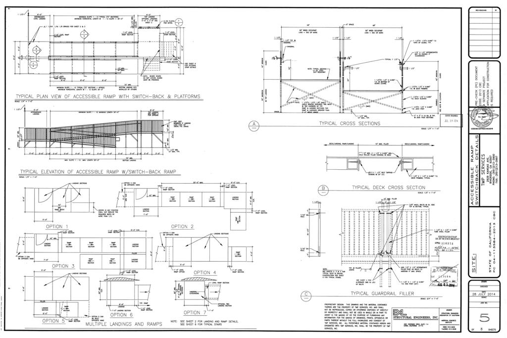
35
36
37
38
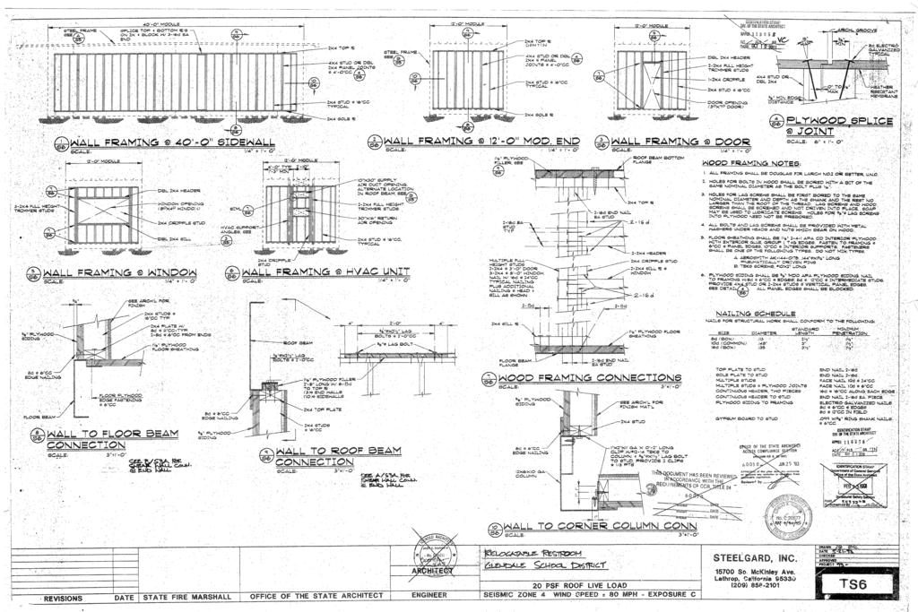
39
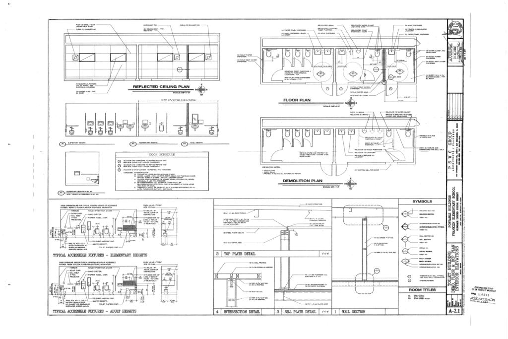
40
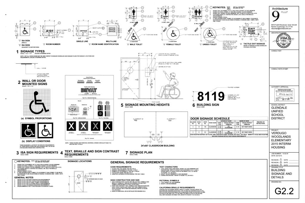
41
42
43
44
45
46
47
 BUILDING COORDINATE P.O.C. OF 4\" SEWER CONNECTION ON DISTRICT PROPERTY COORDINATE P.")
 24'-0\" (E) 21'-0\" CONC. WALKWAY (E) PORT. BLDG. (E) RELOCATABLE CLASSROOM 960 S.F. A# 03-114669 (E) PORT. BLDG. (E) RELOCATABLE CLASSROOM 960 S.F. A# 03-114669 AC DATE: APPL FLS SCHOOL DISTRICT: GLENDALE UNIFIED SCHOOL DISTRICT SS SEWER CONNECTION IN STREET PATH OF NEW 4\" SEWER PIPE, TYPICAL 3'-6\" HGT.")
48 8816 Foothill Boulevard, Suite Rancho Cucamonga, CA ARCHITECTS STAMP: CONCRETE FLOOD CON CONSULTANT: CONSULTANTS STAMP: AUTHORITY APPROVAL: IDENTIFICATION STAMP DIV. OF THE STATE ARCHITECT (E) BUILDING COORDINATE P.O.C. OF 4" SEWER CONNECTION ON DISTRICT PROPERTY COORDINATE P.O.C. OF (N) WATER LINE ON DISTRICT PROPERTY DROP NEW 4" SEWER PIPE DOWN THROUGH EXISTING BERM 24" CONC. RETAINING WALL 4'-0" 12'-0" 7'-0" 40'-0" 4'-0" (E) PORT. BLDG. (E) RELOCATABLE CLASSROOM 960 S.F. A# /- 19'-6" (E) 24'-0" (E) 21'-0" CONC. WALKWAY (E) PORT. BLDG. (E) RELOCATABLE CLASSROOM 960 S.F. A# (E) PORT. BLDG. (E) RELOCATABLE CLASSROOM 960 S.F. A# AC DATE: APPL FLS SCHOOL DISTRICT: GLENDALE UNIFIED SCHOOL DISTRICT SS SEWER CONNECTION IN STREET PATH OF NEW 4" SEWER PIPE, TYPICAL 3'-6" HGT. CMU PLANTER WALL (N) (2) 2" SERVICES AND (N) 2" WATER METERS INSTALLED BY GWP. LOCATION BY GWP. CONTRACTOR TO FURNISH AND INSTALL (N) MANIFOLD FROM (N) METERS FOR CONNECTION TO (N) 3" WATER PIPE 1 PLUMBING PLAN 4" CONC. CURB PATH OF NEW 4" SEWER PIPE, TYPICAL PROVIDE ADDITIONAL NEW CLEANOUTS PER CODE, CONFORM TO GLENDALE BUILDING AND SAFETY FOR TRENCHING (N) CLEANOUT SCALE: 1" = 20'-0" NORTH (N) 3" WATER LINE TYP. CONFORM TO GLENDALE BUILDING AND SAFETY FOR TRENCHING TRUE (E) BUILDING PROJECT: VERDUGO WOODLANDS ELEMENTARY NEW TOILET & BUILDING CERTIFICATION JOB NUMBER: DATE: 02/10/15 REVISION: REVISION: REVISION: DRAWING TITLE: DATE: DATE: DATE: ENLARGED SITE PLAN DRAWING NO.: P1.2
SECTION FIRE ALARM AND SMOKE DETECTION SYSTEMS
 PART 1 GENERAL 1.1 SECTION INCLUDES A. Fire alarm and smoke detection systems 1.2 REFERENCES A. NFPA 72 B. NFPA 101 1.3 REGULATORY REQUIREMENTS A. System: UL listed B. Conform to requirements of NFPA 101
SECTION DIGITAL, ADDRESSABLE FIRE-ALARM SYSTEM
 SECTION 283111 - DIGITAL, ADDRESSABLE FIRE-ALARM SYSTEM PART 1 - GENERAL 1.1 RELATED DOCUMENTS A. Drawings and general provisions of the Contract, including General and Supplementary Conditions and Division
Architect s Project Number of 12 Fire Alarm/Smoke Detection Systems District Master Specs 2013 Edition
 PART 1 GENERAL 1.1 SECTION INCLUDES SECTION 28 31 00 FIRE ALARM AND SMOKE DETECTION SYSTEMS A. Fire alarm and smoke detection systems 1.2 REFERENCES A. NFPA 72 B. NFPA 101 1.3 REGULATORY REQUIREMENTS A.
Moreno Valley Fire Department Fire Prevention Bureau. New and Existing Fire Alarm & Signaling Systems Guideline
 Moreno Valley Fire Department Guideline Approved and Authorized By: Adria Reinertson, Fire Marshal Issued: May 8, 2017 Alarm & Signaling Systems PURPOSE Fire alarm and signaling systems are designed to
COUNTY OF KINGS KINGS COUNTY JAIL EXPANSION PHASE III
 SECTION 28 3111 - DIGITAL ADDRESSABLE FIRE ALARM SYSTEM PART 1 - GENERAL 1.1 RELATED DOCUMENTS A. General provisions of the Contract, including General and Supplementary Conditions and Division 1 Specification
Project No Belleville Fire Hall/Headquarters and Emergency Operations Centre Section Belleville, Ontario Page 1 of 10
 Belleville, Ontario Page 1 of 10 1 GENERAL 1.1 GENERAL REQUIREMENTS.1 The General Conditions of CCDC2-2008, and the General requirements of Division 1, form part of this Section and must read in conjunction
SECTION FIRE ALARM SYSTEMS
 SECTION 28 3100 PART 1 -GENERAL 1.01 RELATED DOCUMENTS Drawings and general provisions of the Contract, including General and Supplementary Conditions and Division 1 Specification Sections, apply to this
The following information shall become and form part of the contract documents.
 October 4, 206 To: Attention: Re: All Bidders All Bidders JCBE Gymnasium HVAC Upgrades BC#: 206433 Edmonds Project No.: BHM6090 All bidders, The following information shall become and form part of the
PWGSC Ontario MULTIPLEX FIRE ALARM SYSTEM Sect Region Project Page 1 Number R
 Region Project Page 1 PART 1 - GENERAL 1.1 REFERENCES.1 CAN/ULC-S524-2006, Standard for the Installation of Fire Alarm Systems..2 CAN/ULC-S525-2007, Audible Signal Device for Fire Alarm Systems..3 CAN/ULC-S526-2007,
OSU PROJECT NO PAGE 1 02 NOV 2006 SECTION FIRE ALARM SYSTEM
 OSU PROJECT NO. 30-04-15 PAGE 1 PART 1 GENERAL 1.1 WORK INCLUDED A. Provide all labor, materials, and equipment required to provide a complete and operating system of manual and automatic detection devices,
Rancho Cucamonga Fire Protection District Prevention Bureau Standard
 Rancho Cucamonga Fire Protection District Prevention Bureau Standard Title: Fire Alarm and Monitoring Systems Standard # 9-3 Effective: May 2002 Number of Pages: 7 Updated: December 2016 for consistency
SANTA CLARA COUNTY Winchester Blvd., Los Gatos, CA (408) (408) (fax)
 (408) (fax)") FIRE DEPARTMENT SANTA CLARA COUNTY 14700 Winchester Blvd., Los Gatos, CA. 95032-1818 (408) 378-4010 (408) 378-9342 (fax) www.sccfd.org STANDARD DETAILS & SPECIFICATIONS Spec No C-4 Rev. Date 03/10/10 SUBJECT:
FIRE DEPARTMENT SANTA CLARA COUNTY 14700 Winchester Blvd., Los Gatos, CA. 95032-1818 (408) 378-4010 (408) 378-9342 (fax) www.sccfd.org STANDARD DETAILS & SPECIFICATIONS Spec No C-4 Rev. Date 03/10/10 SUBJECT:
FIRE & LIFE SAFTEY STANDARD
 Title: Effective Date: 01/01/14 Revised Date: 1/1/14 Code References: Title 16, Chapter 16.16 of the Roseville Municipal Code, NFPA 72 Note: This standard is a summary of Fire Department clarifications
Update all extract references to NFPA documents (including NFPA 72) in Chapter 3 and related annex material to the latest editions.
 in Chapter 3 and related annex material to the latest editions.") 11/16/12 TerraView First Revision No. 15-NFPA 720-2012 [ Global Input ] Update all extract references to NFPA documents (including NFPA 72) in Chapter 3 and related annex material to the latest editions.
11/16/12 TerraView First Revision No. 15-NFPA 720-2012 [ Global Input ] Update all extract references to NFPA documents (including NFPA 72) in Chapter 3 and related annex material to the latest editions.
DIVISION 26 ELECTRICAL SECTION FIRE ALARM SYSTEM
 DIVISION 26 ELECTRICAL SECTION 26 81 11 PART 1 GENERAL 1.01 DESCRIPTION A. Furnish and install all equipment and accessories for a complete local, analog addressable, manually and automatically actuated,
Functional Performance Test
 Fire Alarm Control Panel & Fire Alarm Annunciator Panel Notify all building occupants that testing will be conducted. Fire alarm contractor shall have personnel with 2-way radios at the fire alarm control
Hinesville First United Methodist Church SECTION DIGITAL, ADDRESSABLE FIRE-ALARM SYSTEM
 SECTION 28 3111 DIGITAL, ADDRESSABLE FIRE-ALARM SYSTEM PART 1 - GENERAL 1.01 SUMMARY A. Section Includes: 1. Fire-alarm control unit. 2. Manual fire-alarm boxes. 3. System smoke detectors. 4. Heat detectors.
Bold items are particular to the City of Euless
 EULESS FIRE DEPARTMENT FIRE MARSHAL S OFFICE INFORMATION LINE: Revised 8/2004 Fire Chief Lee Koontz Fire Marshal Paul Smith EFD-FMO 3-1 2003 International Fire & Building Code as Amended NFPA Standards
Smoke Detector Activation of any smoke detector shall start the alarm verification mode.
 Description: The purpose of the section is to provide the UMCP Design Standards for the design and implementation of Fire Alarm Systems at the UMCP campus. Related Sections: TBD Effective Date: July 10,
Concerns: Affects: Dated: June 12, SECTION 1: GENERAL Scope Work Included... 3
 Technical Service Note Detection Systems, Inc. Fairport, New York 14450-9199 Technical Service (800) 374-7454 Sales: (800) 289-0096 and (585) 223-4060 Fax: (585) 223-9180 Concerns: Affects: Dated: June
TABLE OF CONTENTS GENERAL... 2 A. DEFINITIONS DIGITAL, ADDRESSABLE FIRE ALARM SYSTEM... 2
 Division 28 ELECTRONIC SAFETY AND SECURITY TABLE OF CONTENTS 28 0000 GENERAL... 2 A. DEFINITIONS...2 28 3111 DIGITAL, ADDRESSABLE FIRE ALARM SYSTEM... 2 A. DESIGN REQUIREMENTS...2 B. CONSTRUCTION REQUIREMENTS...2
16.34 Multiplex Fire Alarm System Construction Standards Page 1 of 5
 Construction Standards Page 1 of 5.1 General Description.1 The University requires that all new fire alarm system control panel, components, and devices, as required for the project, be Secutron 2900 Series
Data Sheet Fire Safety & Security Products. System Overview. Initiating Circuits SXL-EX FACP 7906
 s Data Sheet Fire Safety & Security Products SXL-EX Fire Alarm Control Panel Conventional Zone Fire Alarm Control Panel ARCHITECT AND ENGINEER SPECIFICATIONS Four (4) zones expandable to eight (8) zones
Specification/ Data Sheet
 Specification/ Data Sheet TRITON RP Agent Release Control Panel FEATURES Agent Release Control Panel designed specifically for suppression release operation with: Four initiating device circuits (IDCs)
Control Panel. 1.0 GENERAL SCOPE OF WORK Introduction... 2
 Architectural & Engineering Specifications Control Panel 1.0 GENERAL... 2 1.1 SCOPE OF WORK... 2 1.1.1 Introduction... 2 1.2 GENERAL CONDITIONS... 2 1.2.1 After-Sales Support... 2 1.2.2 Quality assurance...
SECTION DIGITAL, ADDRESSABLE FIRE ALARM SYSTEM
 SECTION 283111 DIGITAL, ADDRESSABLE FIRE ALARM PART 1 - GENERAL 1.1 GENERAL A. This Section includes the following: 1. Fire-alarm control panel. 2. Manual fire-alarm boxes. 3. Smoke detectors. 4. Heat
HIGH-RISE RETROFIT ORDINANCES - NO and NO
 INFORMATION BULLETIN / PUBLIC - BUILDING CODE REFERENCE NO.: LAMC 91.8604 Effective: 9-06-90 DOCUMENT NO. P/BC 2002-054 Revised: 4-15-03 Previously Issued As: MGD 88 HIGH-RISE RETROFIT ORDINANCES - NO.
Michigan State University Construction Standards FIRE DETECTION AND ALARM PAGE
 PAGE 283100-1 SECTION 283100 - DIGITAL, ADDRESSABLE FIRE-ALARM SYSTEM PART 1 - GENERAL 1.1 RELATED DOCUMENTS A. Drawings and general provisions of the Contract, including General and Supplementary Conditions
SECTION FIRE ALARM STANDARDS REVISED CONSTRUCTION STANDARD
 PART 1 - GENERAL PURPOSE This Standard is intended to assure that fire detection/alarm systems at The University of Texas at Austin provide the highest level of fire safety possible. SCOPE This standard
SECTION AUTOMATIC TRANSFER SWITCHES
 SECTION 26 36 23 AUTOMATIC TRANSFER SWITCHES PART 1 - GENERAL 1.1 RELATED DOCUMENTS A. General provisions of the Contract, including General and Supplementary Conditions and Division 01 Specification Sections,
Lake County / Multi-Department Storage Facility / Project / December 12, 2016 SECTION DIGITAL, ADDRESSABLE FIRE-ALARM SYSTEM
 PART 1 - GENERAL 1.1 RELATED DOCUMENTS SECTION 283111 A. Drawings and general provisions of the Contract, including General and Supplementary Conditions and Division 01 Specification Sections, apply to
SPECIFICATION FOR A TOTAL FLOOD ECARO-25 TM CLEAN AGENT FIRE SUPPRESSION SYSTEM FOR USE WITH THE SHP PRO CONTROL PANEL SYSTEM
 SECTION 1 - GENERAL CONDITIONS SPECIFICATION FOR A TOTAL FLOOD I. SCOPE: This specification outlines the requirements for a Total Flood ECARO-25 TM clean agent fire suppression system utilizing HFC-125
UNIFIED FACILITIES GUIDE SPECIFICATIONS
 USACE / NAVFAC / AFCEC / NASA UFGS-28 31 75.00 10 (November 2008) ----------------------------------- Preparing Activity: USACE Superseding UFGS-28 31 75.00 10 (April 2006) UNIFIED FACILITIES GUIDE SPECIFICATIONS
SECTION FIRE ALARM SYSTEMS
 SECTION 16721 FIRE ALARM SYSTEMS PART 1 - GENERAL 1.01 RELATED DOCUMENTS A. The general provisions of the contract including General and Special Conditions and General Requirements shall apply to all work
SECTION AUTOMATIC TRANSFER SWITCHES
 PART 1 - GENERAL 1.1 DESCRIPTION SECTION 26 36 23 This section specifies the furnishing, complete installation, and connection of automatic transfer switches. 1.2 RELATED WORK A. Section 14 21 00, ELECTRIC
FIRE ALARM SYSTEM 1.1 GENERAL REQUIREMENTS
 VALOUR COMMUNITY CENTRE FIRE ALARM SYSTEM Section 28 00 00 GYMNASIUM ADDITION & RENOVATION Page 1 of 3 28 00 00 FIRE ALARM SYSTEM 1.1 GENERAL REQUIREMENTS 1.2 SCOPE 1. The specification covering the General
Fire Alarm, Water Flow Alarm & Signaling Systems
 Orange County Fire Authority Community Risk Reduction 1 Fire Authority Road, Building A, Irvine, CA 92602 www.ocfa.org 714-573-6100 Fire Alarm, Water Flow Alarm & Signaling Systems Guideline D-03 Serving
NORTHWESTERN UNIVERSITY PROJECT NAME JOB # ISSUED: 03/29/2017
 SECTION 21 2400CA - CLEAN AGENT CHEMICAL SUPPRESSION SYSTEMS PART 1 - GENERAL 1.1 RELATED DOCUMENTS A. Drawings and general provisions of the Contract, including General and Supplementary Conditions and
CITY OF LONG BEACH Department of Development Services BUILDING AND SAFETY BUREAU FIRE ALARM / ELECTRICAL FIRE PLAN REVIEW CHECKLIST
 CITY OF LONG BEACH Department of Development Services BUILDING AND SAFETY BUREAU FIRE ALARM / ELECTRICAL FIRE PLAN REVIEW CHECKLIST DATE: PROJECT NO.: EXPIRATION DATE: STATUS: INFORMATION PROJECT ADDRESS:
1. Floor above/floor below notification. 2. Private alarm notification. 3. Not Used 4. Voice alarm notification. 5. Not Used.
 PART 1 GENERAL 1.01 Scope of Standard A. This Standard is intended to assure that fire alarm and signaling systems at Sam Houston State University provide the highest level of life safety possible. This
CITY OF PORTSMOUTH Department of Public Works MUNICIPAL COMPLEX FIRE ALARM. Bid # Addendum #1
 CITY OF PORTSMOUTH Department of Public Works MUNICIPAL COMPLEX FIRE ALARM Bid #56-09 Addendum #1 This Addendum forms part of the original document marked Bid #56-09 MUNICIPAL COMPLEX FIRE ALARM. Device
A. Provide addressable fire alarm system throughout the facility and supervise wet and preaction fire sprinkler system.
 SECTION 283111 - PART 1 -GENERAL 1.1 RELATED DOCUMENTS A. Drawings and general provisions of the Contract, including General and Supplementary Conditions and Division 01 Specification Sections, apply to
TECHNICAL DATA. multi-hazard. model vfr400. Release Control Panel 290a. January 16, 2014
 January 16, 2014 Release Control Panel 290a 1. Description The Viking VFR400 is a microprocessor based releasing control panel for use on preaction, deluge, Surefire, Firecycle multicycle sprinkler systems,
DONALD H. BERG, ARCHITECT
 DONALD H. BERG, ARCHITECT DVA PROJECT 632-CSI-402 PET/CT ROOM #A0-10 RENOVATION BASEMENT LEVEL, BUILDING 200 ARCHITECT S PROJECT No. 0917-02 ADDENDUM NO. 1 JUNE 25, 2018 Page 1 of 1 ARCHITECTURAL 1. Specifications:
SECTION INTRUSION DETECTION
 (NOTE TO DESIGNER: These Specifications are basic minimum criteria to be met in preparing the final specifications for this section, which is the responsibility of the Designer.) SECTION 28 16 00 INTRUSION
SPECIFICATION FIKE CLEAN AGENT FIRE SUPPRESSION SYSTEM WITH IMPUSLE VALVE, Fike FK AGENT & SHP PRO CONTROL PANEL
 SECTION 1 GENERAL CONDITIONS I. SCOPE: This specification outlines the requirements for a Total Flood Clean Agent Fire Suppression System utilizing FK-5-1-12 as the fire extinguishing agent and with a
SECTION DIGITAL, ADDRESSABLE FIRE-ALARM SYSTEM
 SECTION 13852- PART 1- GENERAL 1.1 RELATED DOCUMENTS A. Drawings and general provisions of the Contract, including General and Supplementary Conditions and Division 1 Specification Sections, apply to this
SPECIFICATION MICROMIST FIRE SUPPRESSION SYSTEM WITH CHEETAH Xi 50 CONTROL PANEL
 SECTION 1 - GENERAL CONDITIONS I. SCOPE: This specification outlines the requirements for a Fike Micromist Water Mist Fire Suppression System with a Cheetah Xi 50 addressable detection and control system.
CONTENTS AUTOMATIC TRANSFER SWITCHES
 CONTENTS AUTOMATIC TRANSFER SWITCHES PART 1 GENERAL 1.1 Related Documents 1.2 Summary 1.3 References 1.4 Quality Assurance 1.5 Submittals 1.6 Delivery, Storage and Handling 1.7 Instructions And Training
SPECIFICATION FOR A TOTAL FLOOD ECARO-25 TM CLEAN AGENT FIRE SUPPRESSION SYSTEM FOR USE WITH THE CHEETAH Xi 50 CONTROL PANEL SYSTEM
 SECTION 1 - GENERAL CONDITIONS I. SCOPE: This specification outlines the requirements for a Total Flood ECARO-25 TM clean agent fire suppression system utilizing HFC-125 as the fire extinguishing agent
SPECIFICATION MICROMIST FIRE SUPPRESSION SYSTEM WITH SHP-PRO CONTROL PANEL
 SECTION 1 - GENERAL CONDITIONS I. SCOPE: This specification outlines the requirements for a Fike Micromist Water Mist Fire Suppression System with automatic detection and control. The work described in
PROJ. NO SECTION PAGING, SPEAKERS AND HARD-WIRED CLOCK SYSTEMS
 SECTION 26 92 50 PAGING, SPEAKERS AND HARD-WIRED CLOCK SYSTEMS PART 1 - GENERAL 1.1 RELATED DOCUMENTS A. Drawings and general provisions of the Contract, including General and Supplementary Conditions
MR-2602 Two Zone Fire Alarm Control Panel
 MR-2602 Two Zone Fire Alarm Control Panel Installation Manual Secutron LT-2015 Rev.3 July 2010 Table of Contents 1 Introduction 1.1 The MR-2602 Fire Alarm Control Unit... 11 1.1.1 General features...
NFPA 72 Code Changes vs 2013
 NFPA 72 Code Changes - 2010 vs 2013 AFAA-NE Westborough, MA February 7, 2018 Richard Roux NFPA 72 National Fire Alarm and Signaling Code Overview and 2013 Changes NFPA 72 1993 Edition Aug 20, 1993 1996
SECTION FIRE ALARM SYSTEM PART 1 GENERAL
 SECTION 16720 - FIRE ALARM SYSTEM PART 1 GENERAL 1.1 SCOPE & RELATED DOCUMENTS A. The work covered by this section of the specifications includes the furnishing of all labor, equipment, materials, and
CARD ACCESS CONTROL SYSTEM
 SECTION 13851 CARD ACCESS CONTROL SYSTEM PART 1 GENERAL 1.01 SUMMARY A. Section Includes: A complete, operable, tested, integrated proximity access control system, to operate on a proximity principle where
OKLAHOMA STATE UNIVERSITY
 ENVIRONMENTAL HEALTH & SAFETY ADDRESSABLE FIRE ALARM SYSTEM STANDARD Revised 6/15 Revised: 6/15 Contact(s) Implementation Date Comments Gerald Petre, EHS June 2016 Review and Update Page 1 1.1 GENERAL
Conventional Releasing Control Panel
 s Data Sheet Fire Safety Products Conventional Releasing Control Panel Pre-Action Deluge Agent-Releasing Fire System Model TXR-320 Remote configurable Up to two (2) hazard areas Operable with the following:
Unified Fire Authority - Fire Prevention Bureau
 Unified Fire Authority - Fire Prevention Bureau FIRE ALARM AND EMERGENCY COMMUNICATION SYSTEM RECORD OF COMPLETION To be completed by the system installation contractor at the time of system acceptance
SPECIFICATION: AlarmLine TM INTELLIGENT LINEAR HEAT DETECTION
 1. GENERAL SPECIFICATION 1.1 The contractor shall provide an Intelligent AlarmLine Linear Heat Detection System to perform the following functionality: A. Fire Alarm, Supervisory and Trouble-Event Initiation
UltraLITE Model ELU Centralized Emergency Lighting Inverter 4.2 KW- 5 KW
 12/23/16 Rev 9 UltraLITE Model ELU General Specification 4.2 KW to 5 KW UltraLITE Model ELU Centralized Emergency Lighting Inverter 4.2 KW- 5 KW 1.0 General General Specification This specification describes
SECTION FIRE ALARM
 SECTION 16740 PART 1 - GENERAL 1.1 RELATED DOCUMENTS A. Drawings and general provisions of the Contract, including General and Supplementary Conditions and Division 1 Specification Sections, apply to this
2. HVAC and smoke control systems; fire, smoke, and combination fire/smoke dampers. 5. Central control and monitoring system.
 PART 1 GENERAL 1.01 Scope of Standard A. This Standard is intended to assure that fire detection/alarm systems at The University of Texas at Austin provide the highest level of fire safety possible.. This
Fire Alarm Acceptance Testing & On-Going Maintenance with The Joint Comm. Standards / Reporting. Prepared Especially for : OSFM TEC 2016
 Fire Alarm Acceptance Testing & On-Going Maintenance with The Joint Comm. Standards / Reporting Prepared Especially for : OSFM TEC 2016 Acceptance Testing 11-2008 Agenda Before you begin Completing the
DESIGN & CONSTRUCTION GUIDELINES
 Facilities Management 4202 E. Fowler Avenue, OPM 100 Phone: (813) 974-2625 Design & Construction Tampa, Florida 33620-7550 Website: usf.edu/fm-dc DESIGN & CONSTRUCTION GUIDELINES DIVISION 28 ELECTRONIC
SECTION Fire Pumps
 SECTION 21 30 00 Fire Pumps PART 1 GENERAL 1.1 WORK INCLUDED A. Furnish, install and test a motor-driven fire pump, jockey pump, and controllers in the space provided and as shown in the contract drawings.
DIGITAL, ADDRESSABLE FIRE ALARM SYSTEM
 SECTION 283111 - DIGITAL, ADDRESSABLE FIRE-ALARM SYSTEM PART 1 - GENERAL 1.1 RELATED DOCUMENTS A. Drawings and general provisions of the Contract, including General and Supplementary Conditions and Division
MANUAL OF DESIGN CRITERIA AND SPECIFICATIONS FOR FIRE DETECTION AND ALARM SYSTEMS PUBLIC SCHOOLS IN NEW MEXICO
 MANUAL OF DESIGN CRITERIA AND SPECIFICATIONS FOR FIRE DETECTION AND ALARM SYSTEMS PUBLIC SCHOOLS IN NEW MEXICO Prepared For: Public Schools Facilities Authority State of New Mexico 2019 Galisteo, Suite
FIRE DETECTION SYSTEM SPECIFICATION FOR MODEL XR200
 FIRE DETECTION SYSTEM SPECIFICATION FOR MODEL XR200 1.0 General 1.1 Manufacturer Manufacturer of the Fire Alarm Control Panel (FACP) equipment shall be: Digital Monitoring Products, Incorporated 2500 N.
SECTION AUTOMATIC TRANSFER SWITCHES
 PART 1 - GENERAL 1.1 DESCRIPTION SECTION 26 36 23 SPEC WRITER NOTE: Use this section only for NCA projects. Delete between //--// if not applicable to project. Also, delete any other item or paragraph
C. All control equipment must have transient protection devices to comply with UL864 requirements.
 SECTION 28 31 11 - PART 1 - GENERAL 1.1 SCOPE & RELATED DOCUMENTS A. The work covered by this section of the specifications includes the furnishing of all labor, equipment, materials, and performance of
TECHNICAL DATA OBSOLETE
 Deluge Devices 270a 1. PRODUCT NAME VIKING PAR-3 Available since 1991 2. MANUFACTURED FOR: THE VIKING CORPORATION 210 N. Industrial Park Road Hastings, Michigan 49058 U.S.A. Telephone: (269) 945-9501 (877)
AL802ULADA. NAC Power Extender. Installation Guide. (See Application Guide for additional information) Rev
 Rev") AL802ULADA NAC Power Extender Installation Guide (See Application Guide for additional information) Rev. 031703 Overview: The Altronix AL802ULADA is an extremely cost effective 8 amp voltage regulated
AL802ULADA NAC Power Extender Installation Guide (See Application Guide for additional information) Rev. 031703 Overview: The Altronix AL802ULADA is an extremely cost effective 8 amp voltage regulated
UNIFIED FACILITIES GUIDE SPECIFICATIONS
 USACE / NAVFAC / AFCEC / NASA UFGS-26 52 00.00 40 (November 2017) ----------------------------------- Preparing Activity: NASA Superseding UFGS-26 52 00.00 40 (August 2014) UNIFIED FACILITIES GUIDE SPECIFICATIONS
MS-4012/4024 and CMS-4012/4024. Instruction Manual for the. Fire Alarm Control Panels
 R 12 Clintonville Road, Northford, CT 06472 Phone: (203) 484-7161 FAX: (203) 484-7118 Instruction Manual for the MS-4012/4024 and CMS-4012/4024 Fire Alarm Control Panels Document 15586 5/11/93 Revision:
TECHNICAL DATA. Humidity: 85% Relative Humidity (non-condensing) at 90 F (32 C) maximum.
 at 90 F (32 C) maximum.") September 29, 1997 Firecycle III 433 a 1. PRODUCT NAME VIKING Model E-1 Manufactured 1997 Present 2. MANUFACTURED FOR THE VIKING CORPORATION 210 N Industrial Park Road Hastings, Michigan 49058, U.S.A.
September 29, 1997 Firecycle III 433 a 1. PRODUCT NAME VIKING Model E-1 Manufactured 1997 Present 2. MANUFACTURED FOR THE VIKING CORPORATION 210 N Industrial Park Road Hastings, Michigan 49058, U.S.A.
The supplier and installer of the system should be approved by the local civil defence authority.
 ANALOGUE ADDRESSABLE FIRE ALARM SYSTEM 1. Scope of Work The contractor shall supply, install, test and commission a modern Analogue Addressable Fire Detection and Alarm System of an approved manufacturer
SPECIFICATION FIKE CLEAN AGENT FIRE SUPPRESSION SYSTEM WITH IMPULSE VALVE, FK AGENT & CHEETAH Xi CONTROL PANEL
 SECTION 1 GENERAL CONDITIONS I. SCOPE: SPECIFICATION FIKE CLEAN AGENT FIRE SUPPRESSION SYSTEM This specification outlines the requirements for a Total Flood Clean Agent Fire Suppression System utilizing
Soft Start Series MP700 Solid State, Reduced Voltage
 Metron Fire Pump Controls and Accessories Soft Start Series MP700 Solid State, Reduced Voltage Metron Fire Pump Controllers conform to the latest requirements of National Fire Protection Association s
DATA SHEET CYBERCAT 254 INTELLIGENT FIRE ALARM CONTROL SYSTEM DESCRIPTION APPROVALS: SYSTEM OPERATION. Form No. D
 DATA SHEET CYBERCAT 254 INTELLIGENT FIRE ALARM CONTROL SYSTEM DESCRIPTION Fike s CyberCat 254 (P/N 10-066) is a state-of-the-art true intelligent digital peer-to-peer modular fire alarm control system.
Florida Building Code Chapter 9 Fire Protection Systems Advanced Course
 Florida Building Code 2010 Chapter 9 Fire Protection Systems Advanced Course 1 Introduction This course will cover specific sections of Chapter 9 that relate to fire alarm systems. While many contractors
GARCIA GALUSKA DESOUSA Consulting Engineers
 L#57297 /Page 1/July 21, 2017 ELECTRICAL SYSTEMS NARRATIVE REPORT The following is the Electrical Systems narrative, which defines the scope of work and capacities of the Power and Lighting systems, as
NORTH HARRIS COUNTY REGIONAL WATER AUTHORITY. Section CHLORINE GAS LEAK DETECTOR
 Section 11263 PART 1 GENERAL 1.01 SUMMARY This Section includes the furnishing and installation of chlorine leak detectors as shown on Plans and specified herein. 1.02 MEASUREMENT AND PAYMENT No separate
good things in small packages
 FireShield Control Panels good things in small packages life safety for small buildings and shops A perfect arrangement FireShield offers the very best conventional fire alarm technology available, with
Environmental Health & Safety
 Environmental Health & Safety Oklahoma State University ADDRESSABLE FIRE ALARM SYSTEM STANDARD Environmental Health and Safety University Health Services Suite 002 Stillwater, OK 74078 (405) 744-7241 www.ehs.okstate.edu
SECTION COMMERCIAL DOOR OPERATORS OVERHEAD RSX FIRE DOOR OPERATOR
 SECTION 08734 COMMERCIAL DOOR OPERATORS OVERHEAD RSX FIRE DOOR OPERATOR Display hidden notes to specifier by using Tools / Options / View / Hidden Text. PART 1 GENERAL 1.1 SECTION INCLUDES A. Overhead
Florida Building Code 2010
 Introduction Florida Building Code 2010 Chapter 9 Fire Protection Systems This course will cover specific sections of Chapter 9 that relate to fire alarm systems. While many contractors are familiar with
COMMISSION ORDER. IT IS FURTHER ORDERED that the Request for Bid and Notice to Bidders be displayed on the Franklin County website.
 4.e STATE OF MISSOURI County of Franklin ss. COMMISSION ORDER Commission Order No. 2016-316 Third Quarter Term 2016 Tuesday,August,09,2016 Bid Notice IN THE MATTER OF ADVERTISING FOR SEALED BIDS FOR SMOKE
Models NFPA 1221-A, NFPA 1221-B Public Safety DAS Annunciator Panel. Revision E 61117
 Models NFPA 1221-A, NFPA 1221-B Public Safety DAS Annunciator Panel Revision E 61117 CAUTION: (Read This First) This panel has been designed to make it nearly bullet proof to mistakes made when wiring
Across-the-Line SERIES MP300 Combined Manual and Automatic
 Across-the-Line SERIES MP300 Combined Manual and Automatic Metron Fire Pump Controllers conform to the latest requirements of National Fire Protection Association s Standard for Centrifugal Fire Pumps
CHEETAH XI INTELLIGENT SUPPRESSION CONTROL SYSTEM
 CHEETAH XI INTELLIGENT SUPPRESSION CONTROL SYSTEM DESCRIPTION Fike s Cheetah Xi (P/N 10-068) is a state-of-the-art true intelligent digital peer-topeer modular suppression control system. It is ideal for
Operation & Maintenance Manual
 Operation & Maintenance Manual for Model 2100 Fire+Smoke systems from Smoke Guard, Inc. 287 N. Maple Grove - Boise, ID 83704 Phone: (800) 574-0330 Fax: (208) 639-7851 E-Mail: info@smokeguard.com Website:
Photovoltaic (Solar) Array Installation Guide
 Array Installation Guide") Building & Safety Division Community Development Department 7351 Rosanna Street, Gilroy, CA 95020 Phone: 408 846-0451 Fax: 408 846-0429 Visit us: www.cityofgilroy.org Photovoltaic (Solar) Array Installation
Building & Safety Division Community Development Department 7351 Rosanna Street, Gilroy, CA 95020 Phone: 408 846-0451 Fax: 408 846-0429 Visit us: www.cityofgilroy.org Photovoltaic (Solar) Array Installation
UNIVERSITY SERVICES ANNEX James Madison University Harrisonburg, Virginia State Project Code: Architect s Project Number:
 SECTION 283112 DIGITAL ADDRESSABLE FIRE ALARM SYSTEM VOICE NOTIFICATION PART 1 GENERAL 1.1 SUMMARY NETWORK FIRE ALARM CONTROL PANEL (NODE) A. Network fire alarm control panels shall include all features
COMMERCIAL (IBC) FIRE ALARM SUBMITTAL GUIDE
 FIRE ALARM SUBMITTAL GUIDE") COMMERCIAL (IBC) FIRE ALARM SUBMITTAL GUIDE SUPERVISION OF AUTOMATIC FIRE SPRINKLER SYSTEMS SUPERVISION OF ALTERNATIVE AUTOMATIC FIRE-EXTINGUISHING SYSTEMS FIRE ALARM AND DETECTION SYSTEMS The Fire Alarm
COMMERCIAL (IBC) FIRE ALARM SUBMITTAL GUIDE SUPERVISION OF AUTOMATIC FIRE SPRINKLER SYSTEMS SUPERVISION OF ALTERNATIVE AUTOMATIC FIRE-EXTINGUISHING SYSTEMS FIRE ALARM AND DETECTION SYSTEMS The Fire Alarm
DS7400Xi Addressable Control/ Communicator
 DS7400Xi Addressable Control/ Communicator DS7400Xi DS7400Xi-EXP 110VAC operation 220VAC operation Remotely Programmable WDSRP (Windows Detection Systems Remote Programming Software), allows the systems
SECTION (13730) - INTRUSION DETECTION
 - INTRUSION DETECTION") PART 1 GENERAL 1.01 SUMMARY A. Section Includes: SECTION 28 16 00 (13730) - INTRUSION DETECTION 1. Intrusion Detection Sensors 2. Signal Equipment 3. System Controls 4. Alarm Displays 5. Alarm Indicating
PART 1 GENERAL 1.01 SUMMARY A. Section Includes: SECTION 28 16 00 (13730) - INTRUSION DETECTION 1. Intrusion Detection Sensors 2. Signal Equipment 3. System Controls 4. Alarm Displays 5. Alarm Indicating
SECTION ADDRESSABLE FIRE ALARM SYSTEM
 SECTION 16720 - ADDRESSABLE FIRE ALARM SYSTEM PART 1 - GENERAL 1.01 RELATED DOCUMENTS A. General: Drawings and general provisions of the Contract, including General and Supplementary Conditions and Division
1.3 REFERENCE STANDARDS
 SECTION 28 4600 FIRE DETECTION AND ALARM PART 1 -GENERAL 1.1 SECTION INCLUDES A. Fire alarm system design and installation, including all components, wiring, and conduit. B. Circuits from protected premises
Installation, Operating and Maintenance Manual
 STATUS ZONES CONTROLS FIRE FAULT DISABLED FIRE 1 2 3 4 5 6 7 8 TEST FAULT DISABLED 1 5 BUZZER SILENCE RESET 1 2 TEST 2 6 LAMP TEST 3 SUPPLY 3 7 SYSTEM FAULT 4 8 SOUNDERS ACTIVATE/ SILENCE 4 FAULTS INSTRUCTIONS