Roboguard Technicians Manual Contents
|
|
|
- Bonnie Martin
- 5 years ago
- Views:
Transcription

1
2 Roboguard Technicians Manual Contents Roboguard 1 Page Roboguard Diagram of Roboguard 2 Installation 3 Walk Test 4 Configuration 5-6 Beam Range 6 Minimising False Alarms 7 Blocking off beams/maintenance 8 Battery Life 9 Exploded View of Roboguard 10 Bracket 11 HQ Diagram of HQ 12 Interpreting your HQ Program mode A (Roboguard 1 4) 15 Program mode B (Roboguard 5 8) 16 Program mode C (Remotes) 17 Connecting a siren 18 Program mode D (output port configuration) Remote Cloning a Remote TX 21 Timer Relay Timer Operating Instructions 22 Keypad Installation 23 Output port programming urx Installation Coding output port 31 Wiring diagram 31 Repeater Wiring Diagram utx Installing a Repeater Station Programming Roboguard or Remote code LED Indicator Wiring Diagram Power Supply Wiring Diagram 40-41

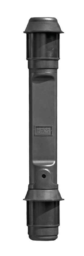

3 Roboguard 2
4 Roboguard 3 Roboguard Installation This instruction assumes the use of the Roboguard HQ as the receiver. For other receivers, please consult the relevant section Determine the desired location of your Roboguards Install 1 Roboguard at a time. Remove the battery cover and plastic battery saver tag (the onboard buzzer will begin beeping in Walk-Test Mode but will reset to silent after 20 minutes or so.) Allow 5 minutes to settle. Mount your Roboguard directly through the mounting guides, or by first installing a mounting bracket. Ensure that the Roboguard is straight (unless you purposefully want it at an angle), a spirit level will help. Allocate your Roboguard a zone on the HQ. (Press and hold the Tamper button on the HQ, after the beep select the required zone, press and release the tamper switch on the Roboguard, press any zone button to reset HQ or see HQ Manual) Walk from left to right and back again in front of your Roboguard to ensure it is triggering the HQ. Distance problems? Check the Walk-Test Mode section. Replace the battery cover and start on your next Roboguard. Don t: Your Roboguard is weatherproof, but don t blast it with a hose or sprinkler. No horizontal spray. Don t install at long distance without first checking reception on the HQ you may need a repeater station. Plan your mounting spot a parked car or an open door could obstruct the Guard. Bear in mind a dog on stairs or a bank can break both beams position your Guard with care (or see blocking off beams ). Do: Ensure your Top beam is above the head (and tail) of your pet. Ensure the intruder has to walk across the beams, not toward them. Roboguards work anywhere on a tree, on the roof, at an angle to cover roofline or sloping ground experiment.

5 Roboguard 4 Walk Test Mode Setting up the beam array for optimal performance After mounting your Roboguard make sure it is detecting intruders. If its range seems very short you will need to adjust the beams to make them level with the ground and parallel to each other. Walk Test allows you to hear the beams as they detect, and make these adjustments. Remember both top and bottom beams need to be broken for the roboguard to detect intruder. 1. Remove the battery cover from the Roboguard, or press and release the tamper switch - the on-board buzzer will activate for about 20 minutes before going silent again. 2. Ensure that the securing screw of both top and bottom sensor boxes is over the middle line of the adjustment slot (see picture). 3. The Roboguard will now buzz once for every time the bottom sensor detects, and twice for every time the top sensor detects. You should hear three buzzes which means that both sensors are detecting. 4. Walk across the path of the beams, from left to right and back again, and keep increasing the distance between you and the Roboguard. If you walk straight towards a guard it is not very efficient and will only detect at close range. 5. If only 1 buzz is heard, only the bottom sensor is detecting you and the top beams are most probably adjusted too high. 6. Top Sensor: Loosen the retaining screw. Sliding the box up will lower the beam, pulling it down will raise the beam (seesaw effect), 1mm adjust will move the beam 1 metre up or down over 10 metres, so make slight adjustments until you hear the beam strike you. Tighten the retaining screw. 7. Follow the same instructions if only the top sensor is detecting you, this time moving the bottom sensor box. 8. Work slowly and methodically and check every beam in the pattern. Pause for 2 seconds between buzzes to catch the next beam. 9. Note: move slowly if only 1 sensor is detecting you the Roboguard takes longer to react (it is waiting for the other sensor to detect).

6 Roboguard Configuration Roboguard 5 Each Roboguard can be set up to work best in specific locations by activating different modes. The default setting is switch 1, ON, all others switches, OFF. The mode switches are located on the computer board inside the bottom sensor box. Remove the bottom sensor screw and pull the box out of the lens holder using your thumb and index finger. Open the sensor box to locate the switches (see below). It is not necessary to unplug the box. The 5-way switch is programmed with the following functions: SWITCH 1: INSTANT DELAYED MODE OFF = The Roboguard will detect three successive intruder signals, then go silent until it has a period of around 30 seconds of no movement before it becomes active again. This is good for high traffic areas. This mode is highly recommended as it saves battery power, and it alleviates the problem of switching off guards. You can leave the guards on all the time without getting annoyed. ON = The guard will send a signal instantly whenever it detects an intruder. SWITCH 2: DOUBLE DETECT MODE OFF = Normal ON = Instructs the guard to verify the intruder by waiting for two detections before sending a signal. Good for areas where there is large foliage. SWITCH 2 AND 3 ON: V DETECTION MODE Instructs the guard to verify the intruder by waiting for two detections from one sensor and another from the other sensor before sending a signal.

7 Roboguard 6 SWITCH 4: SKINNY WINDOW MODE OFF = Roboguard will respond to vertical movement through the beams. It allows a second between breaking top and bottom beams to detect intruder. ON = This mode reduces that tolerance to a second thus allowing slow moving branches to break both beams without detecting intruder. Not good for range over 10 metres. SWITCH 5: DSP MODE OFF = Normal ON = The guard will use a mathematical algorithm to determine whether an intruder has been spotted and helps to minimise false alarms. It is usually used in industrial applications to filter out electromagnetic energy from electronic/radio equipment. Beam Range The two-way switch box (see picture - above) determines beam range and can be adjusted as follows: Full Range (default) Switch 1: OFF, Switch 2: OFF meter range Switch 1: ON, Switch 2: OFF meter range Switch 1: ON, Switch 2: ON NOTE: Full strength in a small area may cause false alarms. Adjustments should be made to both top and bottom sensor boxes.
8 Minimising False Alarms Roboguard 7 The Roboguard uses dual pyro-electric cells to look for changes in movement, light and temperature in its field of view. It is therefore extremely important that the guard is installed in a position that does not inadvertently cause the guard to see changes, which could be reported as false alarms. Identifying false alarms: 1. Situations where the guard is exposed to reflections of sunlight reflecting off water or glass. 2. Situations where the guard is exposed to warm/cold thermals such as a tar driveways. 3. Movement of the structure to which the Roboguard is attached. 4. Moving vegetation between the unit and a significant heat-source (such as the sun). 5. Poor alignment of the sensor beams (see setting up the beam array for optimal performance ). Steps in rectifying constant false alarms: 1. Identify what is causing the false alarms. 2. Move the Roboguard to exclude the problem object/area, remember the entire area doesn t need to be covered, only such that you will be alerted if someone enters this area. 3. Block off the desired beams to exclude problem objects, for example large swaying palm leaves. 4. The sensor boxes may have moved during transport and will need to be realigned to the middle position. (See Setting up the beam array for optimal performance ). 5. In some cases it is not possible to solve a problem with any of these suggestions and the Roboguard needs to be reconfigured (See the Roboguard Configuration section). 6. Use dog biscuits to run dogs through the beam array in walk-test mode to hear if the beams are set correctly. 7. Please contact your local Roboguard dealer if you are not able to solve the problem.

9 Blocking off Beams Roboguard 8 Blocking off of beams is used to narrow the angle of view or to block moving objects such as palm fronds, to prevent false alarms. Blocking off of a beam is done by first, sliding down the fastener ring and removing the UV stable lens. Now using black insulation tape block off the area on the main lens that needs blocking. Use walk-test mode to confirm you have blocked off the area required. Replace the outer lens. Maintenance Roboguards require basic maintenance in order to keep the system performing optimally. You should regularly inspect the guard and remove any signs of infestation (spiders, ants etc). Ants are particularly destructive. Check the field of view of the guards for encroaching vegetation. Once a year the guard s lenses should be cleaned. Dust off all insects. Wipe with a dry cloth. Clean the outer and inner Fresnel lenses with warm soapy water. Clean the pyro- electric cell with a cotton bud. Be careful, do not touch it with your fingers. If you live at the coast, the top and bottom computer boards (inside the sensor boxes) should be cleaned with thinners and resprayed with Tectyl every 3 years. It is also advisable to apply silicon sealer around the connector plug on the top and bottom sensor boxes, to improve moisture resistance.
10 Battery Life Roboguard 9 Roboguard batteries should last for a minimum of three years with alkaline batteries and a minimum of one-year using dry cell batteries. The HQ will inform you of weak batteries when it begins to flash the status light. Remember that it will continue to function normally and reliably for months with weak batteries. When they get really flat Roboguard will become unstable and may trigger constant false alarms. Take your time, don t panic, status is picked up way in advance just change them when you can (see status page in HQ manual). To change the batteries - loosen the locking bolt, remove the battery cover, pull out the batteries and replace with 8 x C size batteries (preferably alkaline). Make sure the batteries are lined up correctly. There are polarity marks (+,-) next to the battery spring to assist. Additional Info: For Maximum Range of beams: remove the outer lens. This will compromise water resistance so drill a hole in the bottom of the Guard to let the water out. Use mothballs inside the housing to keep ants and other insects out. Seal the mounting holes with silicone to keep insects out, or use a bracket and spray the bracket with an exterior insect spray. For Maximum PIR life, seal the plastic sensor boxes around the 5-pin plug and wires, with silicon, after making any adjustments to the configuration and range switches. If you are having difficulty getting range off a single set of beams that are critical, i.e.: where a single set of beams is monitoring an alleyway. Align the white inner main lenses by carefully shifting them to one side or the other (only about 1mm of play). For better range you can mount your Roboguard at an angle to follow a roofline or sloping ground. Always carry a known, working Roboguard with you to diagnose problems. This will allow you to swop out TX and CPU PIR s and check their performance to confirm malfunction.
11 Roboguard 10
12 Roboguard Mounting Brackets Roboguard 11 Roboguard installation using a mounting bracket is highly recommended. The bracket can be mounted to any surface and allows the installer to swivel the Roboguard and aim the beams in the required direction. This is particularly usefull when setting up in walk-test mode as you can also aim the beams between obstacles or down a narrow alleyway. The bracket has top and bottom slots to allow you to set the unit vertical if the mounting surface is not completely vertical. Mount the stainless steel bracket to a solid vertical surface Select a set of locators according to the need per site. i.e. If you are detecting down a hill, choose the lower locators for maximum angle.

13 Roboguard 12
14 INTERPRETING YOUR HQ Roboguard The HQ is a mobile receiver that monitors 1 to 8 Roboguards. 2. The HQ has 4 Zone lights. Each Zone can report on 2 Roboguards. A Green Zone light identifies Active Zones. Each Zone has a button to activate or de-activate the Zone. 3. The HQ has 2 monitor lights, Tamper and Status. These will report on the status or health of every Roboguard. 4. Turn your HQ upside-down there are two holes in the casing. A. One hole towards the front of the HQ through which you can see a Red light indicates your HQ is receiving Robo signals, and when connected to the Charger, a Green light as well indicating the charger is correctly connected. B. Through the other hole you can adjust the volume of the speaker with a small screwdriver. Default setting is full. 5. Active Zones are indicated by a solid green light. Press and release the zone button to turn the zone OFF no light showing, press and release the zone button to turn the zone ON green light showing. If no light comes on there is no Roboguard in that zone. 6. GREEN ZONE LIGHT FLASHING: Indicates intruder the Roboguard(s) connected to that zone has been triggered. The flashing light is merely a visual indicator that the zone has been triggered and does not effect the operation of the system. A. To re-set the light to solid green press the zone button once to turn it OFF, and once again to turn it ON to solid green. B. If the Roboguard is connected in Mode B, re-setting as above will cause the HQ to emit a short low tone bark. 7. RED TAMPER LIGHT FLASHING: Indicates the cover of your Roboguard has been removed. As this happens your HQ will emit 10 beeps and the tamper light will come on. A. To see which Roboguard has been tampered with, press and release the Tamper Button. B. The Tamper Light will burn solid red and the zone light of the Roboguard will be green (solid green for Mode A Roboguards, and flashing green for Mode B Roboguards). C. Press and release the green light button, it will go out, press and release the red light button to re-set. D. Check the Roboguard that has been tampered with. E. A false tamper can be caused by a faulty loom or tamper switch and can be diagnosed if the guard goes into set up mode (starts beeping) when the signal is sent. Also check that the battery cover is correctly seated.
15 Roboguard RED STATUS LIGHT FLASHING: Indicates your HQ is having trouble communicating with one or more Roboguards. The Roboguard sends an auto-test radio signal to the HQ every 20 minutes. From this silent test, the HQ is able to determine the radio signal strength and battery voltage of each guard. If either is low the HQ will indicate this by flashing the red Status light. To establish which Roboguard is reporting the status condition and to reset the light, you must do the following: A. Press and release the Status Button. B. The Status Light will burn solid red and the zone light of the Roboguard will be green (solid green for Mode A Roboguards, and flashing green for Mode B Roboguards). C. Press and release the green light button, it will go out, press and release the red light button to re-set. D. If your system is new, place the HQ in a different location to ensure it has good communication with the Roboguard. E. If your system is a few years old, and the problem persists, change the batteries in the affected Roboguard. F. A faulty TX PIR or CPU PIR can cause the status light to come on. To diagnose, switch the offending TX PIR with another one from the existing installation to see if the problem persists with the same Roboguard or follows the TX to another Roboguard. Replace the offending CPU or TX with a known working product. Always keep a spare set of known working PIR s (or a Demo Roboguard) with you for diagnostics. G. If all else fails, it is possible you have a low range HQ. Always keep a known, working HQ with you for diagnostics. INSTALLER SECTION: Setting up the HQ for the 1 st Time The HQ has 5 outputs, allowing a connection to a siren, to your alarm panel or other devices such as a cell module. These outputs are accessed via the Tele-cable supplied. The HQ is remote ready and its outputs can be remotely activated or de-activated using a Roboguard Remote.

16 To program guards into the HQ, follow these steps: Roboguard Connect the Battery: NOTE: Your dealer may have done this already. This is also a good time to set your output ports see program mode D. 2. Using the Allen key supplied, remove the 4 securing screws at the back of the HQ, locate the battery wire and clip it into the 2 pin box located on the bottom left of the PC board, (see picture below), close the back cover and replace the screws. Connect your HQ to the 12- Volt charger supplied and let it charge for 24 hrs to ensure long battery life. 3. Your HQ is now in Standby Mode. You can now program your Roboguards into the desired Zones on the HQ. 4. Program Modes A and B can each accept 4 Roboguards. If you have more than 4 Roboguards you will have to use both modes, if you have 4 or less then you can choose to use Mode A and/or Mode B. NOTE: Roboguards that share a Zone in Mode A and Mode B will both be turned on and off together, so ensure that they are positioned adjacent to each other in your garden. PROGRAM MODE A: (FIRST 4 ROBOGUARDS) 1. Press and hold the Tamper Button until you hear a beep then release. The Tamper light will burn solid red. 2. Press and release the desired Zone button on the HQ, it will burn solid green.
17 Roboguard Press and release the Tamper Switch on your Roboguard. The Roboguard will sound 4 beeps and transmit a tamper signal, your HQ will emit 10 beeps, and all the lights will flash to indicate successful programming. 4. Press any Zone Button to return to Standby Mode (or the HQ will time-out in 20 seconds). 5. To program the next Roboguard, press and hold the HQ Tamper Button until you hear a beep. The Tamper light will burn solid red and the previously programmed Roboguard Zone (s) will burn solid green. Press and release the desired Zone button on the HQ, it will burn solid green and the other green lights will turn off. 6. Press and release the Tamper Switch on your Roboguard. The Roboguard will transmit a tamper signal, your HQ will emit 10 beeps, and all the lights will flash. Press any Zone Button to return to Standby Mode or let the HQ time-out. 7. When your Roboguard is triggered (intruder) in Mode A: A. The HQ will beep the corresponding number of times as the Zone. The HQ will beep once for Zone 1, twice for zone 2 and so on. B. The green Zone light will start to flash for visual identification of the triggered Roboguard. The green Zone light will continue to flash until it is re-set. This does not affect the operation of your system. C. To reset the flashing Zone light to solid green press the Zone button twice. (Once to turn the Zone OFF disarm, once to turn the Zone back ON re-arm.) PROGRAM MODE B: (ADDITONAL 4 ROBOGUARDS) 1. Press and hold the Status Button until you hear a beep then release. The Status light will burn solid red. (Press Tamper to exit early and effect no changes) 2. Press and release the desired Zone button on the HQ, it will burn solid green. 3. Press and release the Tamper Switch on your Roboguard. The Roboguard will transmit a tamper signal, your HQ will emit 10 beeps, and all the lights will flash to indicate successful programming. 4. Press any Zone Button to return to Standby Mode (or the HQ will time-out in 20 seconds). 5. To program the next Roboguard, press and hold the Status Button until you hear a beep. The Status light will burn solid red and the previously programmed Roboguard Zone (s) will burn solid green.
 in Mode B: A.")
18 Roboguard Press and release the desired Zone button on the HQ, it will burn solid green and the other green lights will turn off. 7. Press and release the Tamper Switch on your Roboguard and continue as above. 8. When your Roboguard is triggered (intruder) in Mode B: A. The HQ will beep the corresponding number of times as the Zone followed by a low tone. B. The green Zone light will start to flash for visual identification of the triggered Roboguard. The green Zone light will continue to flash until it is re-set. This does not affect the operation of your system. C. To reset the flashing Zone light to solid green press the Zone button twice. (Once to turn the Zone off disarm, once to turn the Zone back on re-arm.) To Remove a Roboguard from a Zone: Enter program mode A or B, select the Zone to be removed and press the Status button. Note: When re-setting a Zone that has been triggered in Mode B the HQ will emit a short low-tone bark. This allows you to hear the difference between a Mode A trigger and a Mode B trigger. PROGRAM MODE C: REMOTE CONTROL PROGRAMMING Remote Programming: The remote is only required if you want to use the arm/disarm, panic and silent panic functions. As a default setting, the HQ will trigger its own siren and/or another alarm panel via the Tele-cable provided, for every intruder and/or tamper signal received. A remote programmed in can remotely activate/de-activate these triggers (except siren on a tamper). To enter Remote Programming Mode: Press and hold both Tamper and Status Buttons until you hear a beep. Release the buttons, both Tamper and Status Lights will be burning solid red. Any function already programmed will burn solid green for the activated zones. Every zone in this mode has a different function: Zone 1: ARM/DISARM will only activate/de-activate the connection to the siren or panel. Zone 2: PANIC will activate the siren and a panel connection. Zone 3: SILENT PANIC no siren, panel connection only.
.")
19 Zone 4: AUXILLARY - HQ emits a series of tones, used as a summons for Medical, Doorbell or for testing remotes. Roboguard 18 Select the appropriate zone. The zone light will burn solid green. Press and hold the button on your remote that you wish to use for this function. Any button on the remote can be used (we recommend white - arm/disarm, red- panic). The HQ will emit 10 beeps and all the lights will flash. Press any zone to revert to Standby Mode or let the HQ time out. Repeat the steps above to add more remote functions. To remove a button programmed in: Enter C programming mode, select the zone, and press status. On Remote ARM both Status and Tamper will burn solid RED. Whichever Zones were ON/FLASHING on the HQ (green lights) will be armed. Zones that were OFF will not be included. To turn zones ON or OFF, the HQ must be disarmed. Arming the HQ - your Siren will emit 1 Bark. Disarming the HQ - your siren will emit 2 Barks. If triggered, disarming the HQ - your siren will emit 3 Barks. If the siren is running it can be turned off with the arm/disarm button on your remote, or by pushing any Zone button on the HQ. Your system is still active and the siren will continue to be triggered by active Roboguards until disarmed by remote. The siren will trigger a maximum of 5 times, until re-set. An LED UNIT (visual indicator) is available (sold separately) for switching an external LED-light ON/OFF to indicate alarm status.
20 PROGRAM MODE D: OUTPUT PORT PROGRAMMING Roboguard 19 The HQ can be connected to your alarm panel using the Tele-cable provided with your purchase. You can change the HQ outputs to the panel depending on the number of panel zones available to you. Output Format 1: Monitor all Roboguards separately. Output Format 2: All Roboguards report to a single panel zone. Both Output Formats can be selected to trigger either NORMALLY OPEN or NORMALLY CLOSED circuits. To enter the programming mode: 1. Disconnect 12Volt power and the battery after opening the HQ. 2. Hold down both the Tamper and Status buttons and connect the 12Volt power supply until you hear a beep. Release the buttons. Both red lights will flash and the default Setting 3, ON. 3. Select a Setting 1,2,3,4 from the two tables. 4. Press and release the Tamper button to accept. HQ will beep 10 times and all the lights will flash. Reconnect the battery and replace the cover. OUTPUT FORMAT 1 Setting 1= N/O Setting 3 = N/C (Default) White Zone 1 Black Zone 2 Red Zone 3 Green Zone 4 White Black Red Green OUTPUT FORMAT 2 Setting 2= N/O Setting 4 = N/C Zone1234 Tamper Status Panic/Silent The HQ output wires (white to green) use transistors rated at a maximum of 40mA which is sufficient to switch a relay, timer board or alarm panel. For most alarm panel connections (usually N/C), the HQ zone wire is connected through the in-line resistor of the spare panel zone. The blue is common and should always be connected to the battery VE or common of anything that has its own power source. To check the switching put your multi-meter on Ohms, and measure the resistance between ground (blue wire) and the desired wire (white
21 Roboguard 20 etc). The resistance should change from 0ohm N/C to open circuit N/O or vice-versa. The yellow wire is always N/O, rated at 1Amp and is connected to the siren -ve (generally about 12 Watt, siren positive to external power). Optional Features: (OFF = Default) There is a 4-way DIP switch on the inside of the HQ that provides you with the following optional settings: Switch 1: ON = 3min, OFF = 30sec. (Timing on the siren wire) Switch 2: ON = Future use, OFF = at all times Switch 3: ON = Future use, OFF = at all times Switch 4: ON = entry delay of 30sec, exit delay of 1min 10sec allowing one to exit the property. Only works with remote arm/disarm. When arming the HQ a regular beep will be sound on the speaker followed by a siren bark to indicate armed. If the Remote arm button is pressed for a second time the HQ will arm instantly. On entry, if a Roboguard is triggered the speaker will beep, but after 30 sec the siren and output switches will be triggered if not disarmed. (Entry / exit delay has 5 triggers then will not trigger the siren again) Additional Info: If the HQ is connected to a siren via the yellow wire it will always trigger the siren for Tamper, whether the HQ is armed or not. For siren connections longer than 10 metres use a relay to drive the siren. To avoid the 5-trigger limit on the yellow wire, set your HQ to Setting 2, output format 2. Connect the white wire to a timer relay to drive the siren every time intruder is triggered. To be able to hear the unit arm and disarm via the siren bark, the yellow wire should be connected to the output side of the timer relay. Never put your HQ anywhere near a Remote Blaster (normally used to change DSTV channels from the bedroom). These items have a large area of electro-magnetic interference around them and they can prevent communication with some or all Roboguards. Always carry a known, working HQ with you to diagnose problems.
22 Roboguard Remote TX For use with Roboguard Receivers Roboguard 21 All remotes have unique codes in all four of the coloured buttons To programme the remote into your receiver, follow the instructions in the receiver user manual. TO CLONE A REMOTE: Hold down the button on the slave remote. Keep holding this button down until programming is completed. When the light switches off the slave is ready to be taught the code from the master remote. Position the master remote as close to the slave remote as possible. (Key ring to key ring) Push the corresponding button on the master remote until the light goes off on the master. The light will flash continuously on the slave remote once programming is successful. You can now stop pressing both buttons. Continue with the next button as above. The unit is ready to be tested For maximum transmission hold down the remote button until the LED switches off. Specifications: Transmit Frequency: Encryption: Battery type: Model Number: MHz 24bit Roboguard protocol Gp23a 12V TRX005
23 Timer Robo 5.8 Rev 1 Information Roboguard 22 Power: volts DC Relay: Potential free, 10A Timer Operating Instructions The timer is an adjustable timer from 1 second to approximately 4 minutes. The trigger (TRG) input is negative. TRG and POWER are next to each other to facilitate easy triggering. Once the timer has been triggered it will pull the relay in and light the LED for the programmed duration. The Relay has COM, NC and NO connections Setting the time value 1. Make sure the program link is ON (see Fig 1) 2. Power the unit up. The Led will flash once, and start timing. 3. To end timing remove the link. 4. To finish power the unit down and up again. (With the link open) Fig 1

24 Roboguard 23 Specifications: Dimensions: 104 X 64 X 27 Weight: 100 g Current Consumption: +_ 25 ma Required receiver: Roboguard MHz Required Power Supply: 12V DC The keypad can control, supervise and monitor up to four Roboguards and two Roboguard remote buttons, with individual intruder detected, tamper and supervision LED s, and optional audible warning sounds from the speaker output. The keypad has six highly configurable output switches to connect to other devices/systems. The keypad functions off an external 12V power supply and a Roboguard receiver. The keypad can also be used to monitor other devices via a 4 zone Roboguard Universal Transmitter (electric fence, burglar alarm, and conventional wired sensor).
.")
25 Roboguard 24 The installation involves mounting, wiring, and programming guards, remotes, and output switches. Mounting: Mount the keypad close to the alarm panel or next to the alarm system s keypad (depending on whether you want the data output to go to the System keypad or the System panel). Mount the receiver in a high site that will maximise the radio coverage for the installation area. Wiring: Wire the 12V power to the receiver and the keypad and check that the devices power up. Connect the receiver data line to the keypad. Wire the keypad outputs into the alarm panel zones. See output port wiring. The switch wiring is dependent upon decisions that are made regarding the operation of the keypad, see output port programming. Optionally you may choose to wire-in a speaker or an external horn which will beep for intruder detect. Zone 1, 1 beep, zone 2, 2 beeps etc. NOTE: Reference to beeps assumes a speaker is connected. 1. To enter Roboguard programming mode: hold down the tamper button until a beep is heard and the red tamper LED is solid (ON) You are now in Roboguard programming mode (let go of the button now). Zone LED s that already have Roboguards programmed into them will now be solid (ON). 2. Press and release the button for the desired zone to be programmed (only the desired zone LED and the tamper LED should be ON). 3. Depress and release the tamper lever on the Roboguard to send a tamper signal to the keypad. 4. The keypad will extinguish all the LED s momentarily, 10 beeps will sound and all the LED s will flash. 5. Press any zone button to reset, the
26 Roboguard 25 appropriate zone light should be on solid and can now be tested by triggering the Roboguard. If the Keypad is not yet connected to the alarm panel, you can see the trigger, as the zone light will start to flash after triggering. 6. To erase a Roboguard follow step 1, then select the zone to be erased and press the status button. Press any zone to reset. 7. Continue as above until all your guards are programmed. 1. To enter TX programming mode, hold down the tamper and status button together until a beep is heard. Both the red tamper and status LED s should be solid (ON) to indicate you have entered Remote programming mode (let go of both buttons now). 2. Select either zone one (to learn an Arm/Disarm remote button) or zone two (to learn a panic button). 3. Now transmit using the Remote TX button of your choice corresponding to the function you wish to assign to that button. 4. The keypad will extinguish all the LED s momentarily, 10 beeps will sound and all the LED s will flash. Press any zone button to reset. 5. To erase a remote TX, enter Roboguard remote programming mode as above, select the function (zone 1 = Arm/Disarm, zone 2 = panic) you wish to erase then press and release the status button. 6. NOTE: The remote does not control the zone output ports of the Keypad. The remote will cause the corresponding remote output port to trigger the appropriate alarm panel input. NOTE: These programming modes are separate and you cannot program a remote control as a guard or visa versa. Numbers in the zone column in the table below indicate the output ports that will be triggered for intruder, tamper, status and remote events. In zone 1, ports 1,5 and 6 trigger simultaneously. This will allow additional options in the event of port failure and allows more than 1 device to be triggered. The installer should program the Port operation of the keypad depending on the available zones on the alarm panel and the functionality required.
27 Output Port operation chart Roboguard 26 ZONE 1 ZONE 2 ZONE 3 ZONE 4 1,5, Guard 2 1,5, Guard 3 1,5, Guard 4 1,5, Tamper 1,5,6 5 3 Status Remote Remote Programming Sequence Determine the desired output configuration from the output port chart. Disconnect the power to the keypad. Hold down the tamper and status buttons and simultaneously re-power the keypad. The red tamper and status LED's will now both be flashing, you are now in output port programming mode. Press the desired zone button Press the Tamper Button once to register a N/O selection or the Status Button to register a N/C selection. All LED s will flash and the unit will beep 10 times. Output Port Wiring: The keypad output switches use open collector low-side transistor drivers rated at a maximum of 500mA which is sufficient to switch a relay, timer board or alarm panel. The output voltage is normally held at 0V and will switch open circuit or to an externally connected voltage for 1 second when triggered. To trigger alarm panels you should connect an external 1k ohm (typically) resistor from the port output to the required voltage.
28 Roboguard 27 Ensure that the 0V connections are common between the alarm panel and the keypad. NOTE: DO NOT WIRE ANY POWER ONTO THE OUTPUT PORT PINS. General Operation The keypad is used to supervise and control Roboguards and to report activity audibly (with speaker connected), visually and electronically. The keypad monitors and supervises up to four Roboguards. If an intruder is detected the speaker will beep the number of the zone i.e. zone one, one beep, zone three, three beeps etc; the corresponding LED will flash and the selected output switch will activate. More than 1 keypad can be connected to a single receiver. Roboguard advises not more than 4 Keypads to 1 receiver. GREEN Zone LEDs (zone control and intruder detection) Each of the keypad zones can be individually switched on or off. Switching the zone off does NOT disable the supervision or the tamper monitoring. If the green led for the zone is OFF then the zone is disabled. If it is ON then the zone is ON and not triggered. If it is FLASHING then the zone is ON and has been triggered. Pushing the zone button will change the state of the led from OFF to ON and back again or from FLASHING to OFF to ON. NOTE: Zones which do not have Roboguards programmed in will not function. RED Tamper LED FLASHING (Tamper Detection Triggered) If a Roboguard s is battery cover is removed, a tamper signal will automatically be sent to the keypad. It will sound the speaker 10 times, permanently flash the red tamper LED and activate one of the output switches. To establish which Roboguard was tampered with and to reset the tamper detect LED you must do the following: 1. Press and release the tamper button (tamper LED on, keypad is now in tamper detected display mode) 2. The zone LED for the Roboguard that has been tampered with will be solid (on).
29 Roboguard Press and release all solid (on) LED's so only the red tamper LED is left on. 4. Press and release the tamper button (LED off) or do nothing as the keypad will time out and exit automatically. 5. Determine what caused the Tamper to trigger and correct the problem. NOTE: The Tamper indication will only be sent once per zone, unless the tamper indication is reset. RED Status LED FLASHING (Automatic battery and radio strength test) The status (auto-test) routine is very important. The Roboguard sends an auto-test radio signal to the keypad every 20 minutes. Should a guard fail to report in, the keypad will indicate this by flashing the red status LED and activate an output switch. To establish which Roboguard is reporting the status condition and to reset the status detect LED you must do the following. NOTE: This alarm indicates potential communication problems that may be due to bad radio reception, battery problems or faulty TX or CPU PIRs. 1. Press and release the status button (status LED on, keypad is now in status condition display mode) 2. The zone LED for the Roboguard that is in status will be solid (on). 3. Press and release all solid (on) LED's so only the red status LED is on. 4. Press and release the status button (LED off) or do nothing as the keypad will time out and exit automatically. 5. Determine what is causing the Roboguard to fail auto-test and correct the problem.
30 UNIVERSAL RECEIVER (urx) Roboguard 29 General Operation The urx is used as the receiver for the Keypad and utx (Repeater Station). The Universal Receiver (urx) is also used to remotely trigger the operation of electronic devices using Roboguard signals. The urx can be taught to respond to any particular roboguard radio signal Tamper, Intruder, Auto-test and Remote Tx. (Intruder and Remote are the most common). Once the urx has learned a roboguard code, every time it receives that radio signal, it will respond by triggering a connected device. This connected device may be an alarm system, a camera system, a siren, an SMS module, a timer relay - in fact any device capable of being triggered by an electronic signal. For example, the urx can be programmed to respond to a radio signal from a Roboguard handheld remote. This handheld remote can then be used as a panic button and the urx can be used to trigger an SMS module to send an sms call for help in response to the panic signal. Other popular uses include operating garage doors, switching on external lights and triggering a strike-lock. The installer must connect the urx to a 12V-power source and to the device that you wish to trigger. The installer must also configure the options on the urx to correctly trigger the connected device and must program the transmitter into the urx through a learning process. Installation When used as a data receiver for the utx (repeater) or Keypad, connect 12 volts and 0 volt to the terminals. Connect the data output (RXO) terminal to the Data/RXD input terminals on the Keypad/uTx. (see Repeater Station in this manual)
31 Roboguard 30 The urx will learn ANY roboguard signal - Tamper, Intruder, Auto-test and Remote Tx, unlike the HQ and Keypad modules, which only learn tamper signals. Note that the urx does NOT supervise the radio link. +12V, 0V, Rx Data (RXO) and Trigger (N/C) terminals are clearly indicated on the unit. The I/O1 and I/O2 terminals are not used in this device. The 2-way DIPswitch is used to configure the polarity (SW1) and the Switch timing (SW2). The urx will deliver a 2-second pulse or a 5-minute pulse, depending on timing configuration. (A latched version, the urxl is also available, for latching requirements) The unit has 3 LEDs, one displaying Status of the unit (it will vary its flash rate for different option settings), one displaying RF data and one displaying output. Position the urx in a position suitable for the reception of radio signals from the intended source. Obviously the device to be triggered will need to be located nearby. (Check for radio interference by observing the flashing of the RF LED. If the RF led is flashing brightly and continuously then you may have a problem with radio reception. Confirm this by transmitting from a roboguard product to see how the RF-led flashes for data reception). Wiring See wiring Diagram Below. Wire the urx to +12V and 0V, ensuring the 0V is common with the 0V of the device to be switched. Wire the data line or the trigger (NC) outputs as needed. The NC output is an open-collector low-side driver capable of sinking 500mA continuously. It can therefore be used to drive sirens, relays etc. Should it be used as a data output, use a (type 1k) pull-up resistor at the connected device.
32 Roboguard 31 Coding The device will learn any Roboguard code transmitted while in learn mode. Activate learn mode by using a conductor (like a screwdriver) to short out the program pads on the PCB. The program pads are located between the letter B and the 2-way DIPswitch on the PCB. (See below) The status LED will now remain on (solid) until the device learns a valid roboguard code. Transmit the desired code (Intruder, tamper or remote). Remove the conductor. To confirm the coding, activate the programmed device and check the output LED Note: To send an intruder code, trigger the top and bottom PIR on the Roboguard while the urx is in learn mode. When the code is learned, the status LED will reset back to flashing. Note: If the unit is powered up with the programming input shorted, the unit will erase any learned code. Configuration Place the DIP switches in the required positions as per the information in the connected device s installer manual and the table below. Function ON N/O 5 minute pulse OFF N/C 2 second pulse

33 Roboguard 32 REPEATER - urx and utx The repeater comprises a Universal Receiver (urx) wired to a Universal Transmitter (utx). The urx will pick up any roboguard signal, pass it on to the utx and the signal will be re-transmitted 400 metres. The utx can be configured to delay the re-transmission. Although not often used, this feature is important to determine if the repeater is working properly. By setting a 4 second delay (see utx Manual) with the Repeater, HQ and Roboguard close together, an intruder signal from the Roboguard will trigger the HQ first and the Repeater will trigger the HQ a second time, 4 seconds later. Then reset the utx to default. The default setting will not cause a second HQ trigger. The Repeater station will bounce a roboguard signal over an obstacle such as a hill or building that is obstructing the signal. The repeater should be mounted in a high spot where it can receive the Roboguard signal (you can use an HQ to determine a suitable location inside a roof or on top of a building, for example) and it will then retransmit the signal to the HQ/Receiver.

34 Roboguard 33 The Repeater Station is particularly effective in commercial or residential/townhouse applications, where the receiver is in a Guard hut and the Roboguards are mounted at great distance or in obscure locations. The repeater can be used to improve the range of the Roboguard Remote. The urx and utx housing is not waterproof so the Repeater Station should be mounted under cover or in a suitable waterproof box if outdoors. (see utx Manual for configuration options)
 has four zone inputs that can be wired to any device, such as an Electric Fence, indoor passive, panic button, reed switch etc.")
35 UNIVERSAL TRANSMITTER - utx Roboguard The utx can be wired to a receiver and configured to be a Repeater Station for increased radio distance. 2. The Universal Transmitter (utx) has four zone inputs that can be wired to any device, such as an Electric Fence, indoor passive, panic button, reed switch etc. This will allow these devices to communicate with any Roboguard receiver. The utx can mimic either Roboguards or (not both) Remote Transmitter functions; these unique codes can be programmed into an HQ, Keypad or a Universal Receiver (Roboguard receiver/decoder panels). 3. The input zone sends an intruder signal as soon as the input state is changed (N/C to N/O or vice versa) and will stop sending the supervisory Auto Test signal if it remains in the altered state; thereby monitoring functionality of the devices wired to it. (Auto test signals apply to Roboguard Code only) Switch 1 - ON (Default). In this mode the unit will function as a repeater station. Switch 2, 3, and 4 will implement the following delay time between receiving and transmitting a signal. Delay Switch 2 Switch 3 Switch SEC OFF OFF OFF 2.8 SEC OFF OFF ON 2.8 SEC OFF ON OFF 4 SEC OFF ON ON 4.8 SEC ON OFF OFF 5 SEC ON ON OFF 6.5 SEC ON ON ON
36 Roboguard 35 Repeater Wiring: Connect the Universal Transmitter to a 12V power supply. Connect the 12V, 0V, and RXD (data line) of the Universal transmitter to a Receiver. INSTALLING A UNIVERSAL TRANSMITTER Switch 1 - OFF In this mode the unit will function as a Universal Transmitter. Switch 2 - ON Formatting: Causes the unit to transmit a Code on input state change. Switch 2 - OFF Normal operation. Switch 3 - OFF Causes the unit to transmit Roboguard Code during formatting. Will be programmed into an intruder zone on the receiver. Switch 3 - ON Causes the unit to transmit Remote Code during formatting. Will be programmed into a remote zone on the receiver. Switch 4 ON then OFF Transmitter learns the default input states (N/O or N/C) utx Wiring: Connect the utx to 12V and ground. (+12V, -0V on the unit) PROGRAMMING ROBOGUARD OR REMOTE CODES. The utx can transmit either Roboguard or Remote code. Switch 2 ON will make the utx transmit a code when an input zone is triggered. Each input zone transmits an individual code so the utx behaves like 4 separate Roboguards or Remotes. Switch 3 OFF the code transmitted will be Roboguard Switch 3 ON the code transmitted will be Remote Each input Zone on the utx can take a trigger from normally open or normally closed devices. Connect these devices to the utx via a zone and the common making sure they remain in their non triggered state. Turn switch 2 on and select Roboguard or Remote with switch 3
37 Roboguard 36 Select an input zone on your receiver (this can be a Keypad, HQ or a urx/l one zone only) by following the instructions in the manual. Note: Intruder zones on the receiver will only accept Roboguard Code and Remote zones on the receiver will only accept Remote Code. Now Trigger the device connected to the utx to allow it to send a signal to the receiver and register itself in the zone. Continue with the next device. Ensure all your devices are in their passive state and turn Switch 2 OFF. Leave Switch 3 ON if you are transmitting Remote Code. Turn Switch 4 ON and then OFF. This will register the default state for each device. The LED will now flash to allow you to see what default settings have been selected for the inputs. Zone: flash N/C N/C N/C N/C 2 N/O N/C N/C N/C 3 N/C N/O N/C N/C 4 N/O N/O N/C N/C 5 N/C N/C N/O N/C 6 N/O N/C N/O N/C 7 N/C N/O N/O N/C 8 N/O N/O N/O N/C 9 N/C N/C N/C N/O 10 N/O N/C N/C N/O 11 N/C N/O N/C N/O 12 N/O N/O N/C N/O 13 N/C N/C N/O N/O 14 N/O N/C N/O N/O 15 N/C N/O N/O N/O 16 N/O N/O N/O N/O

38 You can now trigger each device to check transmission to your receiver. Roboguard 37 Finally, connect any unused input zones on the utx to Common. This will stop the utx from sending auto-test data from these zones. AUOTOTEST: The utx will supervise the devices connected when in Roboguard Mode, but not in Remote Mode. If the device does not return to default state but remains in triggered state the utx will fail Auto test on all receivers except the urx. Failed Auto test will trigger the Status LED on your receiver as well as configured output ports depending on your receiver configuration. (See your receiver user manual) NOTE: You can protect the installation by entering the utx into a zone on the receiver using the Tamper Switch on the board. Opening the case will trigger the zone tamper only. HOW TO DETERMINE THE ZONE INPUTS OF AN OLD SITE: Disconnect the Zone input wires one at a time. The N/C zones will transmit on disconnection (LED will burn solid for 1 sec) and with N/O zones, the LED will continue to flash as normal, as they are still N/O
39 LED INDICATOR Roboguard 38 Introduction The LED unit is used to visually indicate the status of the Roboguard system to a distant user. The idea is that the property owner can see whether the alarm has been triggered in their absence and can therefore proceed with caution if this is the case. The unit has 3 internal LEDs: the first one is not used, a solid middle one displays that the processor is running, and the bottom one shows the LED output (NC) status. When the LED unit is powered up the bottom indicator will flash. This is the default state of the unit. This will also alert the user of a possible power failure while they were away. Installation Position the LED UNIT in a position suitable for the control of the LED array (separately purchased) and the sampling of the siren control line (YELLOW wire) from the HQ. It might be best to mount the unit close to the HQ and connect the tele-cable directly to the LED unit. Wiring Wire the LED unit to +12V and GND (0V), ensuring the 0V is common with the 0V of the HQ tele-cable (BLUE wire). Connect the yellow wire from the HQ tele-cable. Please note: There are no power connections available from the HQ. The 12 V power supply has to be supplied separately and is usually the same one powering the siren. Connect the siren and LED array. If a single 3mm or 5mm LED is used it is essential to connect a resistor in-line, as shown. Resistor values are typically 330@ for high-brights and 1k@ for standard ones. Commercial LED arrays should have protection resistors already fitted or should come with instructions on what is needed.

40 Configuration There are no configurable options in this unit. Roboguard 39 Testing The installation must be tested for compatibility with the siren as the siren control line is very noisy and may require additional filtering. Note: Intruder zones on the receiver will only accept Roboguard Code and Remote zones on the receiver will only accept Remote Code. Now Trigger the device connected to the utx to allow it to send a signal to the receiver and register itself in the zone. Continue with the next device. Ensure all your devices are in their passive state and turn Switch 2 OFF. Leave Switch 3 ON if you are transmitting Remote Code. Wiring the board as packaged: Connect GND (0V) to Blue wire from HQ, -VE on power supply and -VE on Siren (if used). Connect IO2 via block to HQ yellow (trigger) wire. Connect relay 12V out via block to Siren +VE (if used). Connect your LED between +12 V with resistor and NC. Connect +12V to power supply; The LED will flash until the HQ has been armed by remote, and thereafter operate normally.
41 ROBOGUARD12 VOLT POWER SUPPLY Roboguard 40 Introduction The 12 volt power supply is used to supply 12 volts to Roboguard products. It is generally used to power a siren connected to a Roboguard HQ. It can also be used to supply power to the urx, utx or repeater station. The unit has a 1,3Ah battery that needs to be charged with an external 16 volt charger. The unit has a 12 volt DC output cable to connect power to the HQ. A Telecable with connectors on either end is used to connect the output ports of the HQ to the power supply. The HQ outputs are all connected to relays that can be configured NO or NC via jumpers between the relays and screw terminals. Siren Wiring To connect a siren, wire the positive wire of the siren into siren+ and the negative wire of the siren into siren -. Please note: The unit is not waterproof. If it is being used to power a repeater station or other remote products, outdoors, it needs to be under cover or in a waterproof box.
. To enter the programming mode on the HQ: 5.")
42 Roboguard 41 Note: Set the HQ to have NO outputs. The LED s on the power supply board should be OFF in the non triggered state. The Output of the power supply board has jumpers to make the outputs NO or NC. (This method greatly reduces the current consumption). To enter the programming mode on the HQ: 5. Disconnect 12Volt power and the battery after opening the HQ. 6. Hold down both the Tamper and Status buttons and connect the 12Volt power supply until you hear a beep. Release the buttons. Both red lights will flash and the default Setting 3, ON. 7. Select a Setting 1,2,3,4 from the two tables. 8. Press and release the Tamper button to accept. HQ will beep 10 times and all the lights will flash. Reconnect the battery and replace the cover. OUTPUT FORMAT 1 Setting 1= N/O Setting 3 = N/C (Default) White Zone 1 Black Zone 2 Red Zone 3 Green Zone 4 White Black Red Green OUTPUT FORMAT 2 Setting 2= N/O Setting 4 = N/C Zone1234 Tamper Status Panic/Silent
43 NOTES Roboguard 42
44 NOTES Roboguard 43
45 NOTES Roboguard 44

46
KwêBeams Effective wire free outdoor early warning system
 1 KwêBeams Effective wire free outdoor early warning system Features: - Easy to install & use - Operates on 868Mhz frequency (less congested to avoid signal jamming) - All sensors with built in sirens,
The most user friendly Security Alarm System L S Section 1 Overview of System Section 2 Planning your Installation
 The most user friendly Contents Section 1 Overview of System 1.1 Kit Contents 1.2 Tools Required 1.3 System Features Security Alarm System L S 4 0 0 Section 2 Planning your Installation 2.1 Location of
Wireless Alarm system s manual
 MOUNTVIEW TECH AUSTRALIA PTY LTD Wireless Alarm system s manual ADS ECO GSM320 Series ADS Security 1/11/2011 1. Before You Begin For your safety and the safety of others, and to ensure that you get the
MEGA WAY LCD 4-CHANNEL MOTORCYCLE ALARM SECURITY SYSTEM. Operation Manual MEGATRONIX CALIFORNIA, U.S.A. MEGA 3100 OPERATE 1
 MEGA 3100 2-WAY LCD 4-CHANNEL MOTORCYCLE ALARM SECURITY SYSTEM Operation Manual MEGATRONIX CALIFORNIA, U.S.A. MEGA 3100 OPERATE 1 MEGA 3100 OPERATE 2 A. TRANSMITTER OPERATION: OPERATION: Transmitter Button
WIRELESS ALARM SYSTEM WITH TELEPHONE AUTO DIALER
 BAT.LOW AC WIRELESS ALARM SYSTEM WITH TELEPHONE AUTO DIALER THE SYSTEM THAT CALLS YOU! Our WIRELESS ALARM SYSTEM WITH TELEPHONE AUTO DIALER is designed to allow you to create your own security system.
Contents. Glossary Introduction to the IDS Notes Understanding the Keypad Indicators Operation of the Keypad...
 2 Contents Glossary...7 1. Introduction to the IDS805...8 1.1 Notes...8 2. Understanding the Keypad Indicators...8 3. Operation of the Keypad...9 4. System Information...10 4.1 Programmed Functions...10
Contents. Glossary
 Contents Glossary ------------------------------------------------------------------------------------------------------ 6 1. Introduction to the IDS 1632 -------------------------------------------------------------
Solution Ultima 862 Operators Manual ISSUE 1.10
 Solution Ultima 862 Operators Manual ISSUE 1.10 Solution Ultima 862 Operators Manual Copyright 2001 by, SYDNEY, AUSTRALIA Document Part Number MA486O DOCUMENT ISSUE 1.10 Printed 24 April 2001 This documentation
USER GUIDE WIRE-FREE HOME PROTECTION SYSTEM AG100+ CONTENTS
 CONTENTS USER GUIDE WIRE-FREE HOME PROTECTION SYSTEM AG00 Section Getting started. General system overview. Introduction to the system. Items included with the system. Introduction to the Smart Panel.5
 Solution-6 Operators Manual Page 1 Preface Congratulations on selecting the Solution-6 security control system for your installation. So that you can obtain the most from your unit, we suggest that you
IDS816 User Manual H Issued January 2009
 1 Contents Glossary-------------------------------------------------------------------------------------------------------------------6 1. Introduction to the IDS 816---------------------------------------------------------------------------7
MOBILE CALL GSM Alarm System User s Manual
 MOBILE CALL GSM Alarm System User s Manual Profile For a better understanding of this product, please read this user manual thoroughly before using it. Contents Function Introduction (3) Alarm Host Diagram
Installation & Programming Guide
 Alert Version 8 Zone Control Arrowhead Alarm Products Ltd Installation & Programming Guide Proudly Designed and Manufactured in New Zealand Arrowhead Alarm Products Ltd PHONE: (09) 579 7506 FAX: (09) 579
Wireless D.I.Y. Alarm Kit
 Wireless D.I.Y. Alarm Kit User Manual December 2010 MAMI 21 Hubert Mathew Road Illiondale 1610 Tel: +27 11 452 4737 Email: sales@mami.co.za page 2/10 General The Wireless DIY kit, is a pre-programmed,
GSM RFID VOICE Alarm System
 GSM RFID VOICE Alarm System User s Manual For a better understanding of this product, please read this user manual thoroughly before using it. CONTENTS [Function Instruction] [Control Panel] Control Panel
Total Connect Box. User manual
 Total Connect Box User manual 1 Congratulations on your purchase of the Honeywell Total Connect Box security system. To make the best out of your system we advise you to read this manual carefully. This
LS800S Intruder Alarm System. Engineering Manual
 LS800S Intruder Alarm System Engineering Manual Table of Contents Section 1 Overview of System 1.1 Kit Contents 1.2 Tools Required 1.3 System Features Section 2 Planning your installation 2.1 Location
Thank you for choosing Ideal Security s Home Security System with Telephone Dialer.
 SK618 WIRELESS ALARM SYSTEM WITH AUTO DIALER OWNER'S MANUAL Thank you for choosing Ideal Security s Home Security System with Telephone Dialer. If at any time during your installation you have any questions
Thank you for choosing Ideal Security s Home Security System with Telephone Dialer.
 SK618 WIRELESS ALARM SYSTEM WITH AUTO DIALER OWNER'S MANUAL Thank you for choosing Ideal Security s Home Security System with Telephone Dialer. If at any time during your installation you have any questions
DYGIZONE GJD910 Lighting Controller & Enunciator
 DYGIZONE GJD910 Lighting Controller & Enunciator MASTER WIRING IDENTIFICATION Power up to the DygiZone and you will see: All the LED s (red,yellow,green and blue buttons) will flash All the LCD icons will
Watchguard WGAP864 User Manual
 Watchguard WGAP864 User Manual v1.0 Issued September 2016 1 2 Table of Contents Glossary... 5 1. Introduction to your Watchguard WGAP864... 6 2. Before Operating your Alarm System... 6 3. Understanding
English. Italiano. Português. Françias. Español
 DT AM Grade 3 Español Françias Português Italiano English High Ceiling Mount Detector Installation Guide English DT AM Grade 3 High Ceiling Mount Detector Installation Guide General Description The Industrial
Wireless Keypads LKP(E)S8M Series
S8M Series") Wireless Keypads LKP(E)S8M Series User manual Contents Congratulations on your purchase of this Honeywell wireless keypad. To make the best out of your equipment we advise you to read this manual carefully.
Wireless Keypads LKP(E)S8M Series User manual Contents Congratulations on your purchase of this Honeywell wireless keypad. To make the best out of your equipment we advise you to read this manual carefully.
Solution Ultima Series Operators Manual ISSUE 1.00
 Solution Ultima Series Operators Manual ISSUE 1.00 Solution Ultima Series Operators Manual Copyright 1998 by, SYDNEY, AUSTRALIA Document Part Number MA488O DOCUMENT ISSUE 1.00 Printed 16 February 1999
IDS800 USER MANUAL. Summary of Operation. + [ ] 2 IDS800 USER MANUAL NO K ISSUED APR 2003 VER 1.44
![IDS800 USER MANUAL. Summary of Operation. + [ ] 2 IDS800 USER MANUAL NO K ISSUED APR 2003 VER 1.44](/thumbs/89/98095999.jpg "IDS800 USER MANUAL. Summary of Operation. + [ ] 2 IDS800 USER MANUAL NO K ISSUED APR 2003 VER 1.44") Summary of Operation A rm/ disarm [#] + [USER CODE] Quick Quick Quick Away Arm Stay Arm Stay Arm & Go H old down [ 1] for 1 second H old down [ 5] for 1 second H old down [ 6] for 1 second Panic Fire Medical
Summary of Operation A rm/ disarm [#] + [USER CODE] Quick Quick Quick Away Arm Stay Arm Stay Arm & Go H old down [ 1] for 1 second H old down [ 5] for 1 second H old down [ 6] for 1 second Panic Fire Medical
3 ZONE WIREFREE BURGLAR ALARM INSTALLATION & OPERATING INSTRUCTIONS
 WIREFREE PIRs WIREFREE KEYPAD AND CASE WIREFREE REMOTE WIREFREE DOOR CONTACT ukpanels.com Please note: Before you start to install this Micromark Alarm, we advise that you should take adequate safety precautions
SK642 THE TELEPHONE DIALER REQUIRES A LAND TELEPHONE LINE TO MAKE OUTGOING CALLS AND ELECTRICITY.
 SK642 WIRELESS WATER ALARM SYSTEM WITH AUTO DIALER OWNER'S MANUAL AND SET UP INSTRUCTIONS. Thank you for choosing Ideal Security s Wireless Water Alarm with Telephone Dialer. Please read through complete
SECURIT 700L PLUS ENGINEERING MANUAL
 SECURIT 700L PLUS ENGINEERING MANUAL C & K Systems Ltd 13/03/97 C031-096-02 NEW ENHANCED FEATURE SET Securit 700L PLUS Engineering instructions INTRODUCTION The Securit 700L is a microprocessor intruder
With Magictrl, you can control MatiGard anytime & anywhere via your smartphone, even without data network.
 MatiGard User Guide 02 Menu Feature-------------------------------------------------------------- 05 Overviews---------------------------------------------------------- 07 Read Before Using-----------------------------------------------
Solution 844 Operators Manual ISSUE 1.10
 Solution 844 Operators Manual ISSUE 1.10 Solution 844 Operators Manual Copyright 2001 by, SYDNEY, AUSTRALIA Document Part Number MA406O DOCUMENT ISSUE 1.10 Printed 24 April 2001 This documentation is provided
Profile. For a better understanding of this product, please read this user manual thoroughly before using it.
 Intelligent GSM Auto-Dial Alarm System User s Manual Profile For a better understanding of this product, please read this user manual thoroughly before using it. Contents Function Introduction (3) Alarm
ARROWHEAD ALARM PRODUCTS Ltd. 344b Rosedale Rd, Albany, Auckland. Ph Fax v1.0
 ARROWHEAD ALARM PRODUCTS Ltd. 344b Rosedale Rd, Albany, Auckland. Ph. 09 414 0085 Fax. 09 414 0088 www.aap.co.nz v1.0 Zone Trouble Shooting (single EOL) = = = = RED, RED, RED, GOLD. = YELLOW, VIOLET, RED,
SMARTWALK DEMENTIA WANDERING SYSTEM
 A division of NESS CORPORATION PTY LTD SMARTWALK DEMENTIA WANDERING SYSTEM SWD Door Responder SWD Resonator SWD-PET (Sold Separately) SWD-PET-BAND (Sold Separately) INSTALLATION MANUAL 1. CONTENTS 1. CONTENTS...1
X64 Wireless Training
 X64 Wireless Training IDS Contents 1 Contents Features 3 Wireless Hardware 4 IDS & Duevi integration PCB 5 LED operation 5 Wireless Device Hardware setup 6 Location 260 7 LED Keypad Instructions 7 Adding
status AW1 Plus WiFi Alarm System User Manual
 status AW1 Plus WiFi Alarm System User Manual Foreword Congratulations on your purchase of the AW1 Plus Alarm system. Before you commence installation we recommend that you unpack the product, familiarise
status AW1 WiFi Alarm System Printed in China PA : AW1-UM-EN-V1.0 User Manual 2016 Chuango. All Rights Reserved.
 status 2016 Chuango. All Rights Reserved. Printed in China PA : AW1-UM-EN-V1.0 AW1 WiFi Alarm System User Manual Foreword Contents Congratulations on your purchase of the AW1 Alarm system. Before you commence
WM3000 WIRELESS MODULES
 WM3000 WIRELESS MODULES $$:05 $$:07 INSTALLATION INSTRUCTIONS Table of Contents Installation... 3 Mounting Instructions & Connections... 3 Setting the Dip Switches... 4 Setting the Recognition Time...
Power Wave Zone Alarm Panel V8.5. Installation Manual
 Power Wave - 8 8 Zone Alarm Panel V8.5 Installation Manual 7 December 2001 Crow (Aust) Electronic Engineering Pty Ltd Corporate Head Office: 429 Nepean Hwy, Brighton East, Vic., 3187 Australia Phone: +61
2G & 3G GSM Wireless Beam Alarm
 2G & 3G GSM Wireless Beam Alarm www.gsm-activate.co.uk MODEL RF - BEAM PAGE 1 Product Information Our 2G/3G GSM Wireless Beam Alarm is a standalone alarm system suitable for indoor and outside use. It
IDM4 CARAVAN ALARM. Operating instructions
 IDM4 CARAVAN ALARM Operating instructions Factory Settings Entry Delay - 0:00 (0 secs) Exit Delay - 0:20 (20secs) Siren On Time - 1:00 (1 minute) Manufacturers Personal Code - 1234 Operation Alarm Keypad
HSA % wirefree security alarm system. Installation Programming Operating. Helpline Intelligent Security & Fire Ltd
 HSA3000 100% wirefree security alarm system Installation Programming Operating Keep in a handy place for reference and for future maintenance Helpline 01902 635998 Introduction General system overview
Phoenix 2 Rev. A - Owner's Manual 0399
 Table of Contents Phoenix 2... 2 Lifetime Warranty...2 Remote Controls....2 Electronic Scan Prevention (ESP)... 3 Instant Remote Control Code Deletion... 3 One-Step Remote Control Code Learning... 3 Valet
A1UL PERS. Personal Emergency Response System. For Technical Support Please Contact Your Service Provider Or Distributor
 A1UL PERS Personal Emergency Response System TABLE OF CONTENTS 1. READ THIS FIRST... 1 2. SYSTEM OVERVIEW.. 1 3. COMPONENTS 2 4. UNIT OPERATION! Standby Mode.. 3! Emergency Activation. 3! Answering Incoming
Solution 880 Operators Manual. Issue 1.00
 Solution 880 Operators Manual Issue 1.00 Solution 880 Operators Manual Copyright 1998 by, SYDNEY, AUSTRALIA Document Part Number MA408O Document ISSUE 1.00 Printed 15 June 1998 This documentation is provided
Elite 16D Version 16 Zone Controller Arrowhead Alarm Products Ltd. Operating Guide. Proudly Designed and Manufactured in New Zealand
 6 Elite 16D Version 16 Zone Controller Arrowhead Alarm Products Ltd Operating Guide 1 Proudly Designed and Manufactured in New Zealand CONTENTS Page No. INTRODUCTION 3 About your Alarm 3 OPERATING YOUR
Destiny Destiny Owners Manual
 Destiny 4100 Destiny 4100 Owners Manual TABLE OF CONTENTS INTRODUCTION Control Panel...3 Detection Devices...3 Telephone Keypads...3 GLOSSARY... 4-5 LOCAL PHONE ACCESS Using Your Telephones As Keypads...6
HILLS Series LED Code Pad User Manual
 HILLS Series LED Code Pad User Manual Not all features may be available on your system Check with your installer to find out which features are programmed Page 2 TABLE OF CONTENTS Code Pad Diagrams...2
LUX Hardwired - Installation Notes
 Ness LUX wired PIR with Nightlight Quad element pyro sensor 15m x 15m wide angle coverage Look down Creep Zone Selectable Standard and Pet Aware modes Adjustable sensor mask for No Creep and Pet modes
Home & Yard Alert Long Range System Home & Yard Alert Extended Long Range System
 Home & Yard Alert Long Range System Home & Yard Alert Extended Long Range System USER MANUAL READ THIS ENTIRE MANUAL PRIOR TO INSTALLATION AND OPERATION We thank you for purchasing this Driveway Alert
DOLKPS1KB Programming & Installation Manual
 VANDAL RESISTANT BACK-LIT WEATHERPROOF ACCESS CONTROL KEYPAD WITH WIEGAND OUTPUT & DATA I/O DOLKPS1KB Programming & Installation Manual FOR ELECTRIC LOCK, INTER-LOCK AND SECURITY SYSTEM INSTALLATIONS DOLKPS1KB
IDS S E C U R I T Y IDS816. User Manual MANUAL NO C ISSUED APRIL 2005 VERSION 2.00
 INHEP DIGITAL IDS S E C U R I T Y IDS816 User Manual MANUAL NO. 700-283-01C ISSUED APRIL 2005 VERSION 2.00 Contents 1. Introduction to the IDS816... 4 2. Understanding the Keypad Indicators... 4 3. Programmable
Congratulations! This manual consists of four sections: SECTION 1 introduces you to the components of your CareTaker system.
 Congratulations! Your purchase of the CareTaker security system is a decision which will afford you greater peace of mind for the many years of service the system is designed to provide. The CareTaker
Installation Instructions
 Request-to-Exit Dual Technology Motion Sensor 1048889B November 2005 Copyright 2005, GE Security Inc. Introduction This is the GE Request-to-Exit Dual Technology Motion Sensor for models -W, -B, and -G.
User s Information Guide R2A
 Pi HSC505 Home Security Controller User s Information Guide R2A Page 1 of 15 of its development program. 1This document and product are copyrighted and all rights are reserved. Introduction Convention
System. For a better understanding of this product, please read this user manual thoroughly before using it.
 GSM Alarm System User s Manual For a better understanding of this product, please read this user manual thoroughly before using it. Chapter 1. Features Chapter 2. Control Panel Introduction Chapter 3.
Quick Installation Manual LED Touch Keypad Autodial Wireless Alarm System
 Quick Installation Manual LED Touch Keypad Autodial Wireless Alarm System By shield4u http:// (Version 20110816) A. Alarm Understanding Away Disarm Home Emergency Function Signal Interpretation Buzzer
OPERATING GUIDE FOR YOUR RP1054D KEYPAD
 OPERATING GUIDE FOR YOUR RP1054D KEYPAD Napco 1992 DESIGN PATS. PENDING Technical Manuals Online! - http://www.tech-man.com CONGRATULATIONS!...on your purchase of a NAPCO Magnum Alert security system.
SPLIT-DECODED CONTROLLER
 SPLIT-DECODED CONTROLLER FOR HAA28XX SERIES SECURITY KEYPADS HAA2801 Programming & Installation Manual FOR ELECTRIC LOCK, INTER-LOCK AND SECURITY SYSTEM INSTALLATIONS VERSION: 11/2012 TABLE OF CONTENTS
V1.0. Smart Home Alarm System. User Manual. APP download via QR Code scanning. Please read the manual carefully before using.
 V1.0 Smart Home Alarm System User Manual APP download via QR Code scanning Please read the manual carefully before using. Content FUNCTION PROFILE 2 THE SCHEMATIC GRAPH OF HOST 3 PROCESS OF BOOTING 6 OPERATION
Power Wave. 8 Zone Control Communicator. Crow Electronic Engineering P/L. Ver:8.54. Installation & Programming Guide.
 Power Wave 8 8 Zone Control Communicator Crow Electronic Engineering P/L Ver:8.54 Installation & Programming Guide 8 November 2000 Crow ( Aust ) Electronic Engineering Pty Ltd Corporate Head Office: 429
Intelligent Wireless GSM Alarm System
 Intelligent Wireless GSM Alarm System 00M2K User s Manual Profile For a better understanding of this product, please read this user manual thoroughly before using it. Contents [Function Instruction] [Alarm
Wireless Keypad GKP-S8M
 Wireless Keypad GKP-S8M User manual Contents Congratulations on your purchase of this Honeywell wireless keypad. To make the best out of your equipment we advise you to read this manual carefully. This
Supervised Security System Owner's Guide
 Owner's Guide PSC06 READ THIS FIRST This equipment generates and uses radio frequency energy, and if not installed and used properly, that is, in strict accordance with the manufacturers instructions,
Understanding the Code Pad lights...4. Code Pad tones...5. Fully arming the system On MODE...6. Fully arming the system - Quick Arm MODE...
 TABLE OF CONTENTS...Glossary of terms...2...code Pad Diagram...3 Understanding the Code Pad lights...4 Code Pad tones...5 Fully arming the system On MODE...6 Fully arming the system - Quick Arm MODE...6
D-Tect 2 GJD300 Quad PIR Movement Detector
 D-Tect GJD0 Quad PIR Movement Detector Package Contents 3. Package Contains: x D-Tect x Drilling template for fixing holes x Allen Key 3 x 3.75mm wall plugs 3 x 3.75mm screws x Spare Sliding Curtains x
TABLE OF CONTENTS TABLE OF CONTENTS 1
 TABLE OF CONTENTS TABLE OF CONTENTS 1 FEATURES 2 Keypad Programmable... 2 EEPROM Memory... 2 Static/Lightning Protection... 2 Supervision... 2 Operation... 2 SPECIFICATIONS 2 PC1550 Control Panel... 2
1pcs. 1pcs. 2pcs 1pcs 1pcs 2pcs
 Home security alarm system GTWAE7-4D Instruction Brief introduction GTWAE7-4D (LX-HS06) is a set of entirely new English home security alarm system, it uses advanced MCU control and SMD technology. it
GJD OPAL RFX WIRELESS 35 METRE EXTERNAL PIR INSTALLATION MANUAL
 GJD OPAL RFX WIRELESS 35 METRE EXTERNAL PIR INSTALLATION MANUAL A WIRELESS PASSIVE INFRARED DETECTOR AND THREE CHANNEL RECEIVER THAT SIMULTANEOUSLY OR INDIVIDUALLY CONTROLS CCTV SWITCHERS, VIDEO RECORDERS
2G & 3G GSM Portable PIR Alarm
 2G & 3G GSM Portable PIR Alarm www.gsm-activate.co.uk MODEL RF - PORTABLE-PIR PAGE 1 Product Information Our 2G/3G Portable PIR Alarm is a standalone alarm system suitable for indoors or outside usage.
Installation and ZONES: Operation Manual. Model: ON STI-34108
 N.O. COM N.C. + 12 V - IN + 12 V - OUT 500 ma 300 ma PLUG IN ADAPTER 12 V 500mA Trigger Output 12 V 75mA N.O. COM N.C. + 12 V - IN + 12 V - OUT 500 ma 300 ma PLUG IN ADAPTER 12 V 500mA Trigger Output 12
ALC-PACK3. WiFi Alarm System with HD WiFi Camera. User Manual. Your Watchguard Wireless Security professional:
 status ALC-PACK3 WiFi Alarm System with HD WiFi Camera User Manual Your Watchguard Wireless Security professional: www.activeonline.com.au 1300 816 742 Foreword Congratulations on your purchase of the
G34 AU1B (External Ultrasonic Sensor) Version 3
 Version 3") Car Alarm Series 3 B 4 Buttons G34 AU1B (External Ultrasonic Sensor) Version 3 24 CAR ALARM GENIUS Series 3B 4 Buttons G34 AU1B (External Ultrasonic Sensor) Module controlled using Micro-Processor 2 Transmitters
Car Alarm Series 3 B 4 Buttons G34 AU1B (External Ultrasonic Sensor) Version 3 24 CAR ALARM GENIUS Series 3B 4 Buttons G34 AU1B (External Ultrasonic Sensor) Module controlled using Micro-Processor 2 Transmitters
CC408. Quick Reference Guide Solution 880
 CC408 EN Quick Reference Guide Solution 880 CC408 Quick Reference Guide Notices EN 2 Copyright Notice Unless otherwise indicated, this publication is the copyright of Bosch Security Systems Pty Ltd ( Bosch
Alarm Control Panel WIC-16Z4P WIC-5Z2P. User Instructions
 WIC-16Z4P WIC-5Z2P User Instructions Page : 2/14 INDEX # Function Page 1 Add a New User Code 11 2 Arm or Disarm All Areas or Disarm Selected Areas (Partitioned System) 8 3 Arming the System (Away Mode)
GSM Alarm System. User s Manual. Profile. MOBILE CALL GSM Alarm System
 MOBILE CALL GSM Alarm System GSM Alarm System System disarmed 11/26/2013 User s Manual Profile For a better understanding of this product, please read this user manual thoroughly before using it. CONTENTS
D-TECT Introduction. Connecting the Unit. Quick Installation. Multi Beam Alignment & Masking. Mounting the Unit
 D-TECT 2 GJD300 Quad PIR Movement Detector Package Contents Package Contains: 1 x D-Tect 2 1 x Drilling template for fixing holes 3 x 31.75mm wall plugs 3 x 31.75mm screws 2 x Spare Sliding Curtains 2
Movement Detector GJD 300
 Movement Detector GJD 300 Installation & Set Up Guide Introduction A CCTV event trigger utilising two independent passive infrared detectors combined in a T05 package. Both sensors have to trigger before
Voice Board. Installation and Programming Guide. Runner 4/8,PowerWave 4/8/16 &, Elite64. Add-on Board For Storing Recorded Voice Messages
 ELECTRONIC ENGINEERING LTD. Voice Board Runner 4/8,PowerWave 4/8/16 &, Elite64 Add-on Board For Storing Recorded Voice Messages And listen-in. Installation and Programming Guide. P/N 7101372 Rev. C V.K
MODEL KP-200 VANDAL RESISTANT & WEATHERPROOF FLUSH MOUNT DIGITAL KEYPAD DESIGNED FOR ACCESS CONTROL APPLICATIONS
 MODEL KP-200 VANDAL RESISTANT & WEATHERPROOF FLUSH MOUNT DIGITAL KEYPAD DESIGNED FOR ACCESS CONTROL APPLICATIONS OPERATES ON 12 OR 24 VOLTS AC/DC, AUTO VOLTAGE SENSING FULLY PROGRAMMABLE FROM THE KEYPAD
RCR-REX Request-to-Exit Dual Technology Motion Sensor Installation Guide
 RCR-REX Request-to-Exit Dual Technology Motion Sensor Installation Guide Introduction This is the Interlogix RCR-REX Request-to-Exit Dual Technology Motion Sensor Installation Instructions for models RCR-REX-W,
INSTRUCTION MANUAL FOR. Remote Control Car Alarm with Impact Sensor, Mini-Battery Backup Siren & Engine Immobiliser
 INSTRUCTION MANUAL FOR Remote Control Car Alarm with Impact Sensor, Mini-Battery Backup Siren & Engine Immobiliser A.C.N 001 621 610 SYDNEY / AUSTRALIA Build Date: TO ARM/DISARM ALARM The alarm is activated
NESS 5000 SERIES DIALLER
 NESS 5000 SERIES DIALLER INSTALLATION MANUAL This manual is designed to provide the installation instructions on the NESS SECURITY PRODUCT'S 5000 SERIES Dialler. For complete details on the warranty or
User s Guide. SUB-MA7240O-0001.OG.Solution doc. Created: 6/05/03. Last Updated: 23/09/03. MA7240AO-0001 Version 1.0
 User s Guide SUB-MA7240O-0001.OG.Solution40-111.doc Created: 6/05/03 Last Updated: 23/09/03 MA7240AO-0001 Version 1.0 2 Table Of Contents User List...6 Quick Reference..7 Features...7 Keypad User's Guide...8
Campers Alert TM Portable System Hunters Alert TM Portable System
 Campers Alert TM Portable System Hunters Alert TM Portable System USER MANUAL READ THIS ENTIRE MANUAL PRIOR TO INSTALLATION AND OPERATION We thank you for purchasing this Driveway Alert System. All our
Premium 8 Zone Wireless Alarm Kit
 Premium 8 Zone Wireless Alarm Kit INTRODUCTION The wireless alarm system is designed to protect your home. It is a simple to use, easy to install unit. No special tools or training are required, all fixings
All-In-One Wireless Security System V1.0. Model #: MG-6060
 All-In-One Wireless Security System V1.0 Model #: MG-6060 Reference and Installation Manual DRAFT Table of Contents Introduction... 5 About Magellan and this Manual... 5 Conventions... 5 Specifications...
TRUST WIRELESS ALARM SYSTEM 200S
 UK TRUST WIRELESS ALARM SYSTEM 200S User s Manual Version 1.0 Thank you Thank you very much for purchasing this product from the Trust assortment. We wish you hours of fun with it. Please read this manual
Independent Zone Control (I.Z.C.)
") Operation and Installation Guide Independent Zone Control (I.Z.C.) DELAYED INSTANT ARMED 1 2 3 4 7 5 6 8 9 * * fi Radionics R D279A Operation & Installation Guide 46456B Page 2 Copyright 2000 Radionics
Operation and Installation Guide Independent Zone Control (I.Z.C.) DELAYED INSTANT ARMED 1 2 3 4 7 5 6 8 9 * * fi Radionics R D279A Operation & Installation Guide 46456B Page 2 Copyright 2000 Radionics
5000 SERIES 8 ZONE INSTRUCTION MANUAL
 5000 SERIES 8 ZONE INSTRUCTION MANUAL NESS SECURITY PRODUCTS 4/167 PROSPECT HIGHWAY SEVEN HILLS. 2147 NSW AUSTRALIA SYDNEY Phone: (02) 8825 9222 (Head Office) BRISBANE Phone: (07) 3343 7744 MELBOURNE Phone:
Elite 64 Version 64 Zone Controller Arrowhead Alarm Products Ltd. Operating Guide. Proudly Designed and Manufactured in New Zealand
 2 Elite 64 Version 64 Zone Controller Arrowhead Alarm Products Ltd Operating Guide Proudly Designed and Manufactured in New Zealand 1 CONTENTS Page No. INTRODUCTION 3 About your Alarm 3 OPERATING YOUR
All-In-One Wireless Security System V3.2 Programming Guide. Model # MG6130 / MG6160
 All-In-One Wireless Security System V3.2 Programming Guide Model # MG6130 / MG6160 We hope this product performs to your complete satisfaction. Should you have any questions or comments, please visit www.paradox.com
HA-263K HA-263D. OWNER'S MANUAL Installation And Operation 8-ZONE ALARM CONTROL PANEL FOR HOME AND OFFICE PROTECTIONS OPEN THE CABINET FOR SERVICE
 D (OPERATION) INITIATE A DYNAMIC BATTERY TEST The system tests the back-up battery once every 24 hours. The owner can initiate a dynamic battery test at any time with the following codes while the system
RONDISH DoorWatcher EASY INSTALL STRIP DOOR MONITOR
 Rondish UI v.04 RONDISH DoorWatcher EASY INSTALL STRIP DOOR MONITOR ( For Curbell only) USER INSTRUCTION Issued 13 June 2017 CONTENTS 1. EQUIPMENT DESCRIPTION 2. INSTALLATION 3. PROGRAMMING AND SETTING
Training Manual with Bi-directional Wireless
 Training Manual with Bi-directional Wireless Installer Training Firmware Version 2.7x X16 Stock Code: 860-1-473-X16 X64 Stock Code: 860-1-864-XS 2 IDS X-Series Training v2.7 Contents Contents 3 X-Series
NetworX NX-548E Receiver Installation Instructions
 NetworX NX-548E Receiver Installation Instructions Content Introduction... 1 Internal mounting... 1 External mounting... 2 Wiring... 3 DIP switch settings... 3 Power up... 3 Programming... 4 Testing and
SPECIAL CODES AUXILIARY CODES SYSTEM NOTES
 Installing/Service Company For Service Call SPECIAL CODES Master Code Duress Code AUXILIARY CODES "Quick Arm" " Chime" 08 02 09 03 10 04 11 05 12 06 13 07 14 SYSTEM NOTES Exit Delay Time Entry Delay Time
2 x CR123A Lithium batteries. White night-light LED. Blue alarm LED - also glows behind the lens. Ambient light sensor behind lens.
 15m x 15m wide angle coverage Look down Creep Zone White LED motion activated night-light Adjustable Pulse Count Adjustable Range High R.F. and E.S.D. immunity High white light immunity SAWR stabilised
SECURITY SYSTEM NOTES SPECIAL CODES ENTRY / EXIT DELAY TIMES ARM / DISARM CODES ZONE DESCRIPTIONS
 SECURITY SYSTEM NOTES Installing/Service Company For Service Call SPECIAL CODES "Chime" Digit 1 "Partial Arm" Digit 2 "Quick Arm" Digit 3 ENTRY / EXIT DELAY TIMES Exit Delay Time Entry Delay Time Secondary
AMX 68 Owner's Manual 12/29/97
 Standard Features Lifetime Warranty We guarantee the operation of the control unit and remote controls for as long as you own your car (see the enclosed warranty card for details). A Pair of AviGlo 3-Button/6-Channel
Active Infrared Multi Beam Sensors
 Active Infrared Multi Beam Sensors D Series TECHNICAL MANUAL INDEX GENERAL SAFETY RECOMMENDATIONS 3 CONFORMITY 4 WARRANTY 4 INTRODUCTION 5 FEATURES 5 OPERATIONAL RANGE 6 SETUP TRANSMITTER (TX) 6 SETUP