C5-12 OPERATION MANUAL
|
|
|
- Philip Clark
- 5 years ago
- Views:
Transcription


1 C5-12 OPERATION MANUAL
2 C5-12 Controls 1 Overview Introduction Model numbers explained Product series overview Hardware Controller Controller Inputs and Outputs Safety and User Information Availability of the operation manual Scope of the operation manual Document format Safety-conscious working Modifications and changes Personnel selection and qualification Closing down procedure Home Page and Status Screens Home Page Unit Status Icons Screen saver Unit Status Active Alarms and Alarm History Alarms and Interlocks Sensor Graph Plots Status Information Pages Navigation Accessing settings Menu Navigation Page Identification Additional Information User Settings Set-points (Level 1.1) Software Version (Level 1.2) Time Control (Level 1.3) Language (Level 1.4) PROTECTION NOTICES The reproduction, distribution and utilization of this document as well as the communication of its contents to others without express authorization is prohibited. Offenders will be held liable for the payment of damages. All rights reserved in the event of the grant of a patent, utility model or design. 2 FläktGroup DC GB /R1 Subject to modifications
3 C5-12 Controls Overview 1 Overview 1.1 Introduction We would like to thank you for purchasing our products. C5-12 Controls are intended and designed for use with DENCO Products in applications of Precision Air Conditioning (PAC and DENCO-OfficeCool products). The controls are designed for refrigeration systems and/or chilled water systems and it is prohibited to use our controls and software for any other purposes. The equipment has been designed and manufactured with a 'Quality Assurance System' within a strict quality controlled environment to ensure that it reaches you in perfect condition. For help, assistance, spares or your local office, please visit the following website for contact details in your region: When contacting please provide details of (if known): Equipment model number Serial Number Date of supply Any order reference numbers Software version of equipment 1.2 Model numbers explained Each product carries an 'Identification Plate' (sometimes referred to as 'serial plate') inside the equipment for indoor units. For outdoor units, this maybe be on the external casing. This identification plate carries information that is important and unique to the unit. Below shows an example serial plate for a Multi-DENCO A-Version unit. Project type Product range Model type code Wiring diagram Standard Serieal number A Ultra-DENCO Contract number DUC100D Date of build Operation manual Voltage 400V / 3PH / 60Hz + N Full load input 22 kw Max. pre-fuse 32 Typ D Full load current 45 A P.E.D SEP Software version CV3.04/DC4.06 Cooling medium Water Max. storage temperature 50 ºC Protection rating IP00 Empty weight 400 Kg Max. working pressures Max. working pressures High pressure N/A MPa Low pressure N/A MPa Chilled water 0,60 MPa DETAILS SHOWN ABOVE ARE ACCURATE AT FACTORY DISPATCH. ANY MODIFICATIONS AFTER THIS POINT WILL NOT BE REFLECTED. REFER TO LATEST VERSION OF THE ELECTRICAL DRAWING. For quick reference on the display, the "Model Type Code" is also shown in the top right corner of the home screen. The text field is entered at the factory and does not need to change. FläktGroup DC GB /R1 Subject to modifications 3

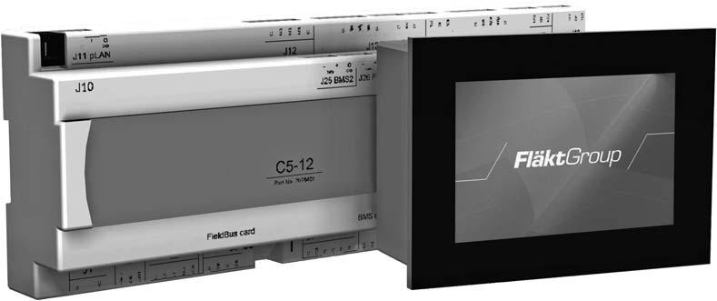
4 Overview C5-12 Controls 1.3 Product series overview C5-12 controls are designed to work across several DENCO products including the different versions within those product range. Some features and settings are not applicable to all products, however with correct setting of the unit type within the controls, only the applicable features are enabled. C5-12 controls are only designed to work in a network with other C5-12 controls products. The controls can provide information and some control features to a Building Management System (BMS). For any support regarding C5-12 controls, please contact your local sales department. 1.4 Hardware Controller 1. Not used 2. Connection to display and DencoNet 3-9. Digital outputs 1 to Inbuilt BMS port (RS485/Modbus or Energy Monitoring if LECUs are fitted) 11. Inbuilt fieldbus port (CPY humidifier and expansion modules) 12. Electronic expansion valve number Electronic expansion valve number RS485 fieldbus interface port (inverter and energy monitoring or LECUs) 15. Optional serial data interface port (e.g. pcoweb / pconet / LonWorks) 16. Not used 17. Suction pressure and temperature analogue inputs V AV power supply 19. 5Vdc supply for discharge pressure transducers 20. Analogue inputs 1 to Analogue inputs 4 to Controller address button 23. Controller address display 24. Power and overload LEDs 4 FläktGroup DC GB /R1 Subject to modifications
5 C5-12 Controls Overview 25. Analogue outputs 1 to Digital inputs 1 to Analogue inputs 6 to Digital inputs 9 to Digital inputs 13 to EEV Ultracap Refer to unit specific wiring diagram for more information on controller connections. 1.5 Controller Inputs and Outputs INPUTS Digital ID1 Unit Remote On/Off 24V AC (Open circuit = unit off) ID2 Airflow Fail 24V AC (Open circuit = alarm condition) ID3 Filter Blocked 24V AC ID4 Heater Over-Temperature Thermostat 24V AC (Open circuit = alarm condition) ID5 Water Detection 24V AC ID6 Sump Pump Failure 24V AC ID7 CombiCool Change-over 24V AC ID8 Generator Run 24V AC ID9 Refrigerant Leak Detection 24V AC ID10 Auxiliary 1 Alarm 24V AC ID11 Auxiliary 2 Alarm 24V AC ID12 Oil Level Switch (092 & 130 models only) 24V AC ID13 Compressor Run Signal (X-Type only) 24V AC Analogue U1 Return Air Humidity Sensor type: 4-20mA U2 Return Air Temperature Sensor type: NTC U3 Supply Air Temperature Sensor type: NTC U4 Water Inlet / Ambient Temperature Sensor type: NTC U5 Water Outlet / Liquid Pipe Temperature Sensor type: NTC U6 Discharge Pressure / CW Feedback Sensor type: 0-5V / 0-10V U7 Discharge Temperature Sensor type: NTC U8 Supply Air Humidity / Airflow Volume Monitoring Sensor type: 4-20mA NOTES! (i) The digital inputs will operate within a voltage range of -15% to +10% (20.4 V to 26.4 V), 50 or 60 Hz. (ii) All digital inputs are functionally isolated from the rest of the controller. (iii) For C5-12 Small; ONLY the following inputs are available: Digital: ID1 ID8 Analogue: U1 U5 FläktGroup DC GB /R1 Subject to modifications 5
6 Overview C5-12 Controls OUTPUTS Digital NO1 Unit Status Relay Output Normally Open Contact NO2 Heater 1 / DODC Heat Open / Thyristor Enable Relay Output Normally Open Contact NO3 Heater 2 / DODC Heat Close Relay Output Normally Open Contact NO4 Compressor 1 / DODC Cool Open / CombiCool Relay Output Normally Open Contact Secondary CW Open NO5 Compressor 2 / DODC Cool Close / CombiCool Relay Output Normally Open Contact Secondary CW Close NO6 Dehumidification Output Relay Output Normally Open Contact NO7 Critical Alarm Relay Output Normally Closed Contact NO8 Maintenance Alarm Relay Output Normally Closed Contact NO9 CombiCool Primary CW DODC Open Relay Output Normally Open Contact NO10 CombiCool Primary CW DODC Close Relay Output Normally Open Contact NO11 FreeCooling Enable Relay Output Normally Open Contact NO12 Shut-Off Damper Enable Relay Output Normally Open Contact NO13 Heat Pump Enable Relay Output Normally Open Contact Analogue Y1 Evaporating Fan 0 10 V DC Y2 Cooling Demand / AmbiCool Demand / CombiCool 0 10 V DC Secondary Valve / Heat Pump Demand Y3 Condenser Fan / Drycooler Fan 0 10 V DC Y4 CombiCool Primary Valve 0 10 V DC NOTES! (i) All digital outputs are relay contacts rated at 24 V DC V AC 10 A fitted with surge suppressor network. (ii) All PCB tracks rated to withstand let through energy of a 24 V AC control fuse (10 A). (iii) All output relay contacts common to 24V AC. (iv) DODC refers to Drive Open/Drive Close valve actuator. (v) The evaporating fan output is to operate alongside the highest demand of either the cooling, heating or humidification. (vi) For C5-12 Small; ONLY the following inputs are available: Digital: NO1 NO8 Analogue: Y1 Y5 6 FläktGroup DC GB /R1 Subject to modifications

 Analogue Output Y1 Remote Humidifier Demand 0 10 V DC c.")

7 C5-12 Controls Overview Expansion Modules The following additional inputs and outputs are available, with an expansion module, when specific options are selected. NOTE! The DIP switches on the expansion modules must be configured as shown below to ensure correct operation. pcoe Expansion I/O Module (address 1) Analogue Input B1 APS (Under Floor Pressure Control) Sensor type: 4-20 ma Analogue Output Y1 Thyristor / Remote Heating Demand 0 10 V DC pcoe Expansion I/O Module (address 2) Analogue Output Y1 Remote Humidifier Demand 0 10 V DC c.pcoe Expansion I/O Module (address 7) Universal Output U1 Thyristor / Remote Heating Demand 0 10 V DC U2 Dehumidification Demand 0 10 V DC NOTE! The default software address is configured as 7. The address is configured in software level 2.6. FläktGroup DC GB /R1 Subject to modifications 7
8 Safety and User Information C5-12 Controls 2 Safety and User Information The C5-12 controller and control strategy has been designed in accordance with stateof-the-art technological and engineering standards as well as in conformity with the recognized safety regulations. It must be used in an appropriate manner for suitable purposes, following the details contained within this manual and taking account of safety aspects and potential hazards. Failure to follow the instructions in this manual may result in danger to health and safety, damage to materials and incorrect unit operation. Information within this document advises on, but is not limited to, potential threats or concerns related to health and safety. All users must be, or employ, a trained professional to, assess issues relating to health and safety, before any use. 2.1 Availability of the operation manual This manual must always be available at the site where unit is operating. Every person working on the equipment must read this manual fully before commencing the work and take note of all relevant information while performing a task. The manual is intended for end users along with service and commissioning engineers. 2.2 Scope of the operation manual THIS IS AN ORIGINAL OPERATION MANUAL VERIFIED BY THE MANUFACTURER. This document has been developed by the manufacturer specifically for details relating to the C5-12 controller and associated control strategy. Information within this document is non-transferable. The information should not be used as a basis for any other products. Every effort is made to ensure that information contained within this manual is fair and accurate, but FläktGroup endeavours to continuously update and improve all of our products for our customers. Due to this continuous development, some information contained within this manual may become outdated or no longer relevant. If you are in any doubt regarding any information contained within this document, please contact your local sales or support representative who will be happy to assist and enquire further for you. 2.3 Document format Significant information for each chapter will be highlighted in the following format: NOTE! Here you will find additional details on using the Multi-DENCO unit. This symbol is used to indicate normal lists. This symbol indicates instructions to follow. The result of an action is indicated with this symbol. 8 FläktGroup DC GB /R1 Subject to modifications
 are easily flammable.")
9 C5-12 Controls Safety and User Information 2.4 Safety-conscious working The following is initial general advice to consider during various stages of a project. More information can be found in the relevant Operation Manual for the product design At all times Filters (especially used or dirty filters) are easily flammable. Leaking refrigerant can catch fire and emit noxious substances. No smoking is allowed in direct proximity of any aspect of the Multi-DENCO system. No open flames near the system Whenever opening/removing any panel/grille/door You must wear suitable Personal Protective Equipment (PPE) at any point working with a unit from the DENCO Products range. As a minimum we recommend: Wear safety footwear Wear eye protection Wear protective gloves Wear protective clothing If operating for a prolonged period of time, noise reducing ear protection may be required. Always conduct your own personal risk assessment to evaluate any further requirements When unit is operational At any time the unit is operational, rotating machinery and electrically charged components are present. When the unit is not electrically isolated: Ensure all guards and doors are closed. Only remove guards or open doors: When the unit has been electrically isolated. Sufficient time has been allowed for the rotating fan momentum to cease. Sufficient time has been allowed for inverter circuits to discharge. 2.5 Modifications and changes Modification to the C5-12 control or display software, language, programming or design is not permitted and will invalidate warranty. Any requests for modifications, after the unit has been installed must be made through your local or regional office. FläktGroup DC GB /R1 Subject to modifications 9
10 Safety and User Information C5-12 Controls 2.6 Personnel selection and qualification Any individual working on the unit must read and understand all of this manual before starting any works. Any individual working on this system shall be suitably qualified and licensed for the region that the system in installed within. All personnel involved with the system must understand and observe any local legislation regarding safe working practice. 2.7 Closing down procedure It is essential for starting, closing down, emergency operation and fault finding to know the location of the following components: Location of isolator for power distribution to the unit Main Isolator (integral to unit or local position) ON/OFF icon on the display of the unit All valves likely to affect water supply to humidifier (if fitted) NOTE! The units are designed for continuous operation and it is recommended that the system is kept running overnight and at weekends to maintain stable room conditions. Short periods Long periods Indefinitely Should you require the equipment to be closed down for the weekend or Bank Holidays, no special precautions are required. Each unit may simply be turned off by pressing the On/Off icon. Alternatively, the "On/Off Times" can be configured in the controller software. If the plant is to be shut down for longer periods (up to a month) this can be done by switching off at the on/off icon, then opening the Main Isolator, and closing the local mains water supply to the humidifier. When re-starting the plant, follow the same instructions but in the reverse order. When the equipment is to be taken out of service for an indefinite period we recommend a qualified air conditioning engineer. An engineer will also be required for the restarting of the equipment. For units fitted with chilled water cooling and/or hot water heating, the mains power should remain "ON" for at least the stroke time of the valve actuator to ensure that the valve closes fully. 10 FläktGroup DC GB /R1 Subject to modifications

11 C5-12 Controls Home Page and Status Screens 3 Home Page and Status Screens 3.1 Home Page The 'Home Page' is the controller's default display. You can return to this page by pressing the 'Home button' on any screen. NOTICE When starting the unit, during the start-up procedure: Do not touch the screen during start-up It will take approximately 40 seconds for the home page to display When the 'Home Page' is shown, you can use the interface Fig Unit ON/OFF Use this button to turn the unit ON or OFF, without removing the power supply (Units Status = OFF by keyboard). 2. Unit Status This display what state the unit is in (see chapter 3.4). 3. Alarm Use this to see any active alarms and alarm history (see chapter 3.5). 4. Graphs Plots Use this to see the history of the sensor values (see chapter 3.7). 5. Access Use this to gain access to settings menu (see chapter 4.1). 6. Status Information Use this to view the unit's status (see chapter 3.8). 7. Control Air Temperature Depending on the options fitted, this value could be return or supply air and could be internal to the unit or remotely positioned. 8. Control Air Humidity Depending on the options fitted, this value could be return or supply air and could be internal to the unit or remotely positioned. 9. Unit Number This is used for networking. 10. Model Reference The model short code of the unit design. Information Bar The below features are part of the information bar. The information bar is at the top of all screens on the software. 11. Active Alarm This symbol will flash if there is an active alarm. 12. Date The date configured in the unit. 13. Unit Function Icons This symbols show what operations the unit is currently performing: fans operating, heating, cooling, humidification control (both humidification and dehumidification). 14. Unit Number This is the same number as number Network Status This shows whether the network connection is healthy or disconnected. 16. Time The time configured in the unit. 17. Help On some pages, additional information can be displayed by pressing this button. FläktGroup DC GB /R1 Subject to modifications 11

 shown when there is an un-healthy connection between the Controller and Display. 3.")
12 Home Page and Status Screens C5-12 Controls 3.2 Unit Status Icons UNIT RUNNING shown when the unit's fan(s) are running. COOLING shown when cooling demand is greater than 0%. HEATING shown when heating demand is greater than 0%. HUMIDIFYING shown when humidification demand is greater than 0%. DEHUMIDIFYING shown when dehumidification demand is greater than 0%. Network Status (Healthy) shown when there is a healthy connection between the Controller and Display. Network Status (Fault) shown when there is an un-healthy connection between the Controller and Display. 3.3 Screen saver The screen saver is activated when the screen has not been pressed for 15 minutes. Screen saver when unit has no active alarms. Screen saver when unit has active alarms. 12 FläktGroup DC GB /R1 Subject to modifications
 can be any of the following; Unit On Off by Alarms Off by BMS The unit is operating. Disabled due to an alarms that requires a unit to be stopped for protection of equipment or environment.")
13 C5-12 Controls Home Page and Status Screens 3.4 Unit Status The unit status on the Home page (see balloon 2 on Fig. 3-1) can be any of the following; Unit On Off by Alarms Off by BMS The unit is operating. Disabled due to an alarms that requires a unit to be stopped for protection of equipment or environment. Disabled by a BMS signal to stop the unit. Off by Time Zone Disabled due to the time control settings in Level 1.3. Off by DI Off by Keyboard On HOA Mod Stand-by On Generator Mode Disabled due to a break in the remote stop/start connection. The unit has been switched off by the on/off icon on the display. Any of the units outputs has been configured for Hand operation. Unit is configured for a DencoNet auto change-over and is currently in stand-by. There is a 24 Vac signal on ID8 and the unit is operating in 'cooling only' mode. 3.5 Active Alarms and Alarm History Where this button is shown, you can press it to see the active alarms page (shown in Fig. 3-2). If there is no active alarms, this button will be black instead of red. Fig Use these checkboxes to select specific alarms. 2. Use this to reset any selected alarms. 3. Use this to select all alarms. 4. Use this to see the Alarm History (see Fig. 3-3). 5. Use this to see the Graph Plots (see chapter 3.7). 6. Use this to return to the Home Page. 7. Use this scroll through the alarm list. FläktGroup DC GB /R1 Subject to modifications 13

14 Home Page and Status Screens C5-12 Controls After selecting 'Alarm History', Fig. 3-3 is shown. The software can display 28 days of alarms. On the 29th day, these alarms will over-write the 1st day's alarms. Fig Alarm event and description - the date is in the format MM/DD/YYY. 2. Use this drop down menu to change the view to show more or less history. The range is from 5 minutes to 4 weeks. 3. After changing the history duration, this 'refresh' button will update the list to show the correct alarms. 4. Use this to scroll through the alarm list. 5. This allows you to export the alarm history to a USB memory device (SD card not available). The USB port is on the under-side of the PGD touch display. The information is exported into a Comma Separated Values (CSV) file. 3.6 Alarms and Interlocks Alarm Description Relay Activated Reset Function Comments Airflow Failure Critical Manual Switches unit off. Filter Blocked Maintenance Manual Relay operation selectable in software. Heater Over-Temperature Alarm Critical Manual Electric heater over-temperature thermostat activated and disables heater outputs. Water Detection Critical Manual Disable humidifier operation. Note: there is an option to select the whole unit to be disabled in the event of a water alarm. Auxiliary Alarms 1 & 2 Maintenance Manual Custom text and relay operation selectable in software. Sump Pump Failure Critical Manual Disables humidifier operation. Refrigerant Leak Detection Return Air Temperature Sensor Failure Critical Manual Monitoring only. Critical Auto Disables temperature control outputs. 14 FläktGroup DC GB /R1 Subject to modifications
15 C5-12 Controls Home Page and Status Screens Alarm Description Relay Activated Reset Function Comments Return Air Humidity Sensor Failure Discharge Pressure Sensor Failure Water Inlet Temperature Sensor Failure Water Outlet Temperature Sensor Failure Supply Air Temperature Sensor Failure Supply Air Humidity Sensor Failure Air Volume Pressure Sensor Failure APS Pressure Sensor Failure Ambient Temperature Sensor Fail Discharge Temperature Sensor Failure High Control Air Temperature Alarm Low Control Air Temperature Alarm High Control Air Humidity Alarm Low Control Air Humidity Alarm Low Supply Air Temperature Alarm High Supply Air Humidity Alarm Critical Auto Disables humidity control outputs. Critical Auto Critical Auto Activates CombiCool secondary circuit Critical Auto Monitoring only. Critical Auto Disables temperature control outputs (if selected as supply air temperature control). Critical Auto Disables humidity control outputs (if selected as supply air humidity control). Critical Auto Unit fans revert to Normal operation when selected as Air Volume Control. Critical Auto Unit fans revert to Normal operation when selected as APS Control. Critical Auto Disables FreeCooling. Critical Auto Critical Auto Monitoring only. Critical Auto Monitoring only (only activated if heating function selected). Critical Auto Monitoring only (only activated if dehumidification function selected). Critical Auto Monitoring only (only activated if humidification function selected). Critical Auto Monitoring only (only activated if supply air temperature control and heating function selected). Critical Auto Monitoring only (only activated if supply air humidity control and dehumidification function selected). CPY Offline Critical Auto No communication between the CPY humidifier module and the C5-12 controller. Parameters Not Downloaded (CPY) High Current Alarm (CPY) Lack of Water Alarm (CPY) Critical Manual Humidifier configuration incorrect. Disables humidifier operation. Maintenance Manual Excessive current drawn by humidifier. Disables humidifier operation. Maintenance Manual No water supply to humidifier or the bottle has reached the end of its operational life. Disables humidifier operation. FläktGroup DC GB /R1 Subject to modifications 15
16 Home Page and Status Screens C5-12 Controls Alarm Description Relay Activated Reset Function Comments High Conductivity Alarm (CPY) Low Production Alarm (CPY) Humidifier Cylinder Full Alarm (CPY) Maintenance Manual Excessive conductivity measured by conductivity probes. Disables humidifier operation. Maintenance Manual Humidifier not achieving target current. Disables humidifier operation. Maintenance Manual Water reaches high level probes in humidifier bottle. Disables humidifier operation. pcoe Offline Critical Auto No communication between the C5-12 controller and the expansion module used for thyristor heating and/or APS. pcoe 2 Offline Critical Auto No communication between the C5-12 controller and the expansion module used for remote humidifier. C,pCOe Offline Critical Auto No communication between the C5-12 controller and the expansion module used for remote dehumidifier. BMS Offline None Manual No communication between the C5-12 controller and the BMS when BMS Comms Alarm enabled. Denconet Communication Alarm Energy Meter Device Off Line None Manual No communication with other units on a Denconet network. None Auto No communication to the power meter. Clock Alarm None Manual Fault on C5-12 controller. No effect to unit functionality. LECU Offline None Auto No communication between LECU and C5-12 controller. Circuit LP Threshold Alarm Circuit HP Threshold Alarm Low Pressure Switch Alarm High Discharge Gas Temperature Low Pressure Differential Alarm Critical Manual LP alarm threshold reached (default 2.5 bar) and disables cooling operation. Critical Manual HP alarm threshold reached (default 41 bar) and disables cooling operation. Critical Manual LP switch activated and disables cooling. Note: DMA092 &130 only. Critical Manual Discharge pipe temperature exceeds 120 C and disables cooling operation. Critical Manual After five attempts to re-start, the differential between the suction and discharge pressures is less than 1.3bar and disables the cooling operation. Envelope Alarm Critical Manual Compressor operating outside of the envelope limits for 4 hours and disables the cooling operation. Low Superheat Critical Manual Superheat below alarm threshold (default 2K) for longer than 60 seconds. Low Evaporating Temperature High Evaporating Temperature High Condensing Temperature Low Suction Temperature Critical Manual Evaporating temperature envelope low limit reached. Critical Manual Evaporating temperature envelope high limit reached. Critical Manual Condensing temperature envelope high limit reached. Critical Manual Evaporating temperature envelope low limit reached. 16 FläktGroup DC GB /R1 Subject to modifications
17 C5-12 Controls Home Page and Status Screens Alarm Description Relay Activated Reset Function Comments Low Discharge Superheat Alarm High Discharge Superheat Alarm Critical Manual Discharge Superheat below 12K for longer than 10 minutes. Critical Manual Discharge Superheat above 50K for longer than 10 minutes. EEV Motor Error Critical Manual Electronic expansion valve not communicating to C5-12. Power+ Device Off Line Inverter Model Not Compatible Danfoss Inverter Off Line Danfoss Inverter Alarm Danfoss Oil Protection Mode Alarm Power+ Drive Disabled Power+ Drive Over Temp Power+ Motor Phase Failure Power+ Over Voltage Power+ Under Voltage Power+ Speed Failure Power+ Over Current Failure Critical Auto No communication with Power+ Inverter, normally occurs when there is no mains power supply to inverter. Cooling will not operate. None Manual Incorrect configuration. Cooling will not operate Critical Auto No communication with Danfoss inverter (models 092 & 130 only). Cooling will not operate. Critical Manual Inverter compressor fault (models 092 & 130 only). Critical Manual Optical oil sensor detects low oil level following oil recovery cycle (models 092 & 130 only). Critical Auto HP safety switch activated. Critical Auto Inverter electronics temperature limit reached. Critical Auto Power supply to inverter disrupted. Critical Auto Inverter detects a high voltage supplied to compressor. Also a symptom of an over condensing condition. Critical Auto Inverter detects a low voltage supplied to the compressor. Critical Auto Inverter unable to manage the correct rotor speed. This normally occurs during start-up and is caused by the presence of liquid in the compressor. Critical Manual Excess compressor current measured. Also a symptom of the system operating with a high discharge temperature. NOTE! There is an option in the software to disable the whole unit in the event of a compressor alarm, i.e. cooling disabled. FläktGroup DC GB /R1 Subject to modifications 17

18 Home Page and Status Screens C5-12 Controls 3.7 Sensor Graph Plots Fig Values on graph - the colour of the text represents the colour of the line on the graph. Values that can be shown are: Supply Air Temperature C Return Air Temperature C Chilled Water Outlet Temperature C Return Air Relative Humidity % Supply Air Relative Humidity % 2. Scroll forward in time 3. Scroll backwards in time 4. Refresh the graph 5. Change the scale of the X-axis (time) 6. Change the scale of the Y-axis (sensor values) NOTE! The graph will only show sensors that are installed and are set to 'Fitted' in the settings (Level 3.3A). 18 FläktGroup DC GB /R1 Subject to modifications


19 C5-12 Controls Home Page and Status Screens 3.8 Status Information Pages Press this icon on the Home page to show a series of pages that show status and sensor values. Use the left and right arrows to navigate to different pages. Once you have navigated past the last page, it will go back to the first page. As standard the following pages are shown: Setpoint & Demand Status Sensor Status Sensor Status - Expansion Only if the equipment is installed and enabled in the settings are these pages shown: LECU(s) Status Airflow Status (requires Air Volume Monitoring) Humidifier Status Energy Meter FläktGroup DC GB /R1 Subject to modifications 19


20 Home Page and Status Screens C5-12 Controls 20 FläktGroup DC GB /R1 Subject to modifications
 on the home page and enter the required code. 4.2 Menu Navigation Use the blue 'up and down' arrows to move through the different menu options.")


21 C5-12 Controls Navigation 4 Navigation 4.1 Accessing settings To access settings you must press the 'Login' button (Fig. 3-1, balloon 5) on the home page and enter the required code. 4.2 Menu Navigation Use the blue 'up and down' arrows to move through the different menu options. Once the option is in the centre of the screen, press the option to open. When you are in a sub-menu, the name of the parent level is shown in yellow on the right hand side of the screen. In this example, we are in: Level 1 General User Option 3. Time Control Option 1. On/Off Times Setup is highlighted 4.3 Page Identification Every page in controls software has a reference number as part of the title. This helps to identify which menu level you are using. It shows the settings level, then any sub menus and finally uses letters to represent multiple pages inside one option. Some pages in an option may be hidden due to settings or options not being enabled. In the below example, this page is found in: Level 1 General User Option 3 Time Control Option 1 On/Off Times Setup Page B (the 2 nd page) 4.4 Additional Information Use the blue help icon in the top right corner of the screen for advice or tips regarding that setting page: FläktGroup DC GB /R1 Subject to modifications 21
 Simply press on the temperature or humidity value for a keypad to display and allow you to change the set-points.")
 This option displays: pgd touch software version pco software version BOOT version BIOS version 22 FläktGroup")
22 User Settings C5-12 Controls 5 User Settings The password for this level is: Set-points (Level 1.1) Simply press on the temperature or humidity value for a keypad to display and allow you to change the set-points. The maximum and minimum values are shown on the keypad 5.2 Software Version (Level 1.2) This option displays: pgd touch software version pco software version BOOT version BIOS version 22 FläktGroup DC GB /R1 Subject to modifications

23 C5-12 Controls User Settings 5.3 Time Control (Level 1.3) These options are typically used for DENCO-OfficeCool applications (comfort cooling). These settings allow you to define specific times for the unit to be ON and OFF. The control can go further to allow for different set-points for temperature and humidity at these times. Page A Page B Page C In "ON/OFF Times Setup" (Level 1.3.1): Enabled / Disable the setting Create different profiles for the units to turn ON/OFF Assign the profiles to days of the week. NOTE! F1 has 2 parts to its profile: F1-1 and F1-2. If a day is assigned F1, it will use both those profiles, in that order, each day. In the Temp. Setpoint (Level 1.3.2) and Hum. Setpoint (Level 1.3.3) you can define up to 4 times of the day where the set-points change each day. You must add the times in order for Z1 to Z4, otherwise the set-point will be ignore. 5.4 Language (Level 1.4) Several languages are available in the standard software. Simply click on the flag to activate the language. FläktGroup DC GB /R1 Subject to modifications 23


24 FG_DC GB_C5-12 Controls_OM_R Copyright 2018 FläktGroup C5-12 CONTROLS FläktGroup is the European market leader for smart and energy efficient Indoor Air and Critical Air solutions to support every application area. We offer our customers innovative technologies, high quality and outstanding performance supported by more than a century of accumulated industry experience. The widest product range in the market, and strong market presence in 65 countries worldwide, guarantee that we are always by your side, ready to deliver Excellence in Solutions. PRODUCT FUNCTIONS BY FLÄKTGROUP Air Treatment Air Movement Air Diffusion Air Distribution Air Filtration Air Management Air Conditioning & Heating Controls Service» Learn more on or contact one of our office
Multi-Denco. » Precision Climate Control. Air Conditioning & Heating. Multi-DENCO
 Air Conditioning & Heating Multi-DENCO Multi-Denco» Precision Climate Control Promise Precision control is more than just an industry term, it is a promise. A promise we sustain using our extensive experience.
Dryer Controller M720
 User Manual Dryer Controller M720 Hardware version 2.00 Software version 2.00 Manual M720 Dryer controller Page 1 of 60 Document history Preliminary version: - Created in April, 2009 Hardware Version 2.00,
High Density Cooling Systems
 OPERATION MANUAL Close Control Units Controller for Row-DENCO High Density Cooling Systems Table of Contents Controller for Row-DENCO 1 Safety and User Information... 4 1.1 Availability of the operation
ModSync Sequencing System Installation & Operation Manual. For use with Fulton Steam Boilers.
 ModSync Sequencing System Installation & Operation Manual For use with Fulton Steam Boilers. Revision 3.0 8/21/2008 - 2 - Table of Contents Introduction Page 4 Features Page 4 Sequence of Operation Page
User Manual. Dryer Controller M720
 User Manual Dryer Controller M720 Hardware version 1.00 Software version 1.00 Preliminary version Manual M720 Dryer controller Page 1 of 42 Document history Preliminary version: - Created in April, 2009
OPERATION MANUAL Close Control Units Multi-DENCO. Precise, flexible and efficient
 OPERATION MANUAL Close Control Units Precise, flexible and efficient Table of Contents 1 Overview of Units and Scope of Supply... 13 1.1 Introduction... 13 1.2 Model number explained... 13 1.3 Product
Multi-DENCO OPERATION MANUAL
 OPERATION MANUAL Table of Contents Multi-DENCO 1 Overview of Units and Scope of Supply... 13 1.1 Introduction... 13 1.2 Model number explained... 13 1.3 Product series overview... 14 1.4 DENCO-OfficeCool...
Emerson Inspire 1HDEZ Installation Instructions. Thermostat/Interface Equipment Control TROUBLESHOOTING
 Emerson Inspire 1HDEZ-1521 Installation Instructions Thermostat/Interface Equipment Control TROUBLESHOOTING FAILURE TO READ AND FOLLOW ALL INSTRUCTIONS CAREFULLY BEFORE INSTALLING OR OPERATING THIS CONTROL
CAIRfricostar CAU Controller with Remote Control SUPPLEMENT TO OPERATION MANUAL
 CAIRfricostar CAU Controller with Remote Control SUPPLEMENT TO OPERATION MANUAL Table of Contents CAIRfricostar CAU Controller Table of Contents 1 Functional description of the unit... 3 1.1 Operation
OPERATING INSTRUCTIONS
 COMFORT CONTROL CENTER 2 THERMOSTAT OPERATING INSTRUCTIONS PROGRAMMABLE THERMOSTAT MODEL 3314080.000 BLACK 3314080.015 WHITE USA SERVICE OFFICE Dometic Corporation 1120 North Main Street Elkhart, IN 46514
DC 60 & DM 60 displays
 USER MANUAL DC 60 & DM 60 displays BALTIC FLEXAIR ENERGY AIRCOOLAIR COMPACTAIR FLATAIR (& Inverter) AQUALEAN DC60-DM60-IOM-1310-E www.lennoxemea.com Summaries 1 Display DC60 1.1 Introduction... 2 1.2
I/O logger box. User manual NO POWER & SIGNAL CABLES TOGETHER READ CAREFULLY IN THE TEXT!
 I/O logger box User manual NO POWER & SIGNAL CABLES TOGETHER READ CAREFULLY IN THE TEXT! H i g h E f f i c i e n c y S o l u t i o n s WARNING DISPOSAL CAREL bases the development of its products on decades
Follett Performance Plus
 Follett Performance Plus touchscreen user guide The next level of control in undercounter refrigeration Controller Operation - Performance Plus touchscreen Use and care of the LCD Performance Plus touchscreen
Modular Standard HP Chiller 1/4 screw compressor with Carel driver
 Program for pco¹ pco 2 and pcoc Modular Standard HP Chiller 1/4 screw compressor with Carel driver Manual version 1.0 25 September 2003 Program code: FLSTDmMSDE Do we want you to save you time and money?
Spa Touch Control Panel with BP2100, BP6013 spa controllers. (Spa Owner s Manual insert)
") Spa Touch Control Panel with BP2100, BP6013 spa controllers. (Spa Owner s Manual insert) P.N. 7876C (export) February 12, 2015 For Spas equipped with BP2100, BP6013 controllers and Spa Touch panel. Spa
Spa Touch Control Panel with BP2100, BP6013 spa controllers. (Spa Owner s Manual insert) P.N. 7876C (export) February 12, 2015 For Spas equipped with BP2100, BP6013 controllers and Spa Touch panel. Spa
Operation manual. Rooftop Packaged Unit
 Operation manual Rooftop Packaged Unit odels: UATYQ20ABAY1 UATYQ25ABAY1 UATYQ30ABAY1 UATYQ45ABAY1 UATYQ50ABAY1 UATYQ55ABAY1 UATYQ65ABAY1 UATYQ75ABAY1 UATYQ90ABAY1 UATYQ110ABAY1 UATYQ115ABAY1 UATYQ20AFC2Y1
READ AND SAVE THESE INSTRUCTIONS
 XXXXXXX-0 EN 1904 READ AND SAVE THESE INSTRUCTIONS BASIC-PLC CONTROLLER MANUAL For all Condair desiccant dryer with equipped with Basic- PLC valid from version: PLC-35/PLC-45 18.04.03 Dehumidification
TECHNICAL MANUAL CVM 20 C 5005 CV/04-99 GB
 Summary 1 CONNECTIONS... 3 1.1 TEMPERATURE PROBES...3 1.2 LOW VOLTAGE DIGITAL INPUTS...3 1.3 LIVE DIGITAL INPUTS...4 1.4 RELAY OUTPUTS...5 2 POWER SUPPLY... 6 3 SERIAL CONNECTIONS... 6 4 SOFTWARE... 7
Installation Instructions / User s Manual TSTAT0406 and TSTAT0408
 997-060180-5 Installation Instructions / User s Manual TSTAT0406 and TSTAT0408 4 HEAT 2 COOL DUAL FUEL TSTAT0406 & TSTAT0408-4 WIRE CAPABLE THERMOSTAT (NAXA00201DB Daughter Board sold separately) LEFT
Tri-Stack Smart System
 Tri-Stack Smart System TM Notes & Warnings - The protection provided by this equipment may be impaired if it is not used in the manner specified herein. - Ensure all wiring meets applicable national and
CONTROLS MANUAL For all Innovent and Valent air handling products
 CONTROLS MANUAL For all Innovent and Valent air handling products TABLE OF CONTENTS TABLE OF CONTENTS IMPORTANT INFORMATION Safety information...................................................................................
Adaptive CyCLO Technical and HMI User Guide. CyCLO User Guide. Version th December 2017 REV
 CyCLO User Guide Version 2.00 19 th December 2017 REV 2.00 1 Contents 1. Hardware... 3 1.1. Introduction... 3 1.2. Electrical Specification... 3 1.3. Board Overview... 4 1.4. Electrical Installation...
SMARTELEC 2 ENERGY SAVING CONTROL INSTALLATION AND OPERATING MANUAL
 Instruction Manual. SMARTELEC 2 SmartElec ENERGY SAVING CONTROL INSTALLATION AND OPERATING MANUAL 0 F1 INDEX Section General information ------------------------------------------------------------ 1 Dimensions
i.c³ User Guide For Helmer i.series Ultra-Low Freezers A/A
 i.c³ User Guide For Helmer i.series Ultra-Low Freezers 360175-A/A Document History Revision Date CO Supersession Revision Description A 18 APR 2014* 9275 n/a Initial release. * Date submitted or change
HIGH EFFICIENCY FIRETUBE CONDENSING GAS BOILER
 This manual must be left with owner and should be hung on or adjacent to the boiler for reference. US HIGH EFFICIENCY FIRETUBE CONDENSING GAS BOILER MODELS CHS-85 through CHS-399 APPENDIX A CONTROLLER
C-TRAC3 COMMUNICATION MANUAL FOR. BACnet NOVEMBER 2010 TO JANUARY 2014 USA HEAD OFFICE AND FACTORY
 A C-TRAC3 COMMUNICATION MANUAL FOR BACnet NOVEMBER 2010 TO JANUARY 2014 UNIT MODEL NO. UNIT SERIAL NO. SERVICED BY: TEL. NO: CANADIAN HEAD OFFICE AND FACTORY 1401 HASTINGS CRES. SE CALGARY, ALBERTA T2G
Spa Touch Control Panel with 2000, 2100 controllers. (Spa Owner s Manual insert)
") Spa Touch Control Panel with 2000, 2100 controllers (Spa Owner s Manual insert) P.N. 7876B February 11, 2015 For Spas equipped with BP2000, BP2100 controllers and Spa Touch panel. Spa Touch Control Panel
Spa Touch Control Panel with 2000, 2100 controllers (Spa Owner s Manual insert) P.N. 7876B February 11, 2015 For Spas equipped with BP2000, BP2100 controllers and Spa Touch panel. Spa Touch Control Panel
Refrigeration Controller Operator s Manual (HRC) PO Box 6183 Kennewick, WA
 PO Box 6183 Kennewick, WA") Refrigeration Controller Operator s Manual (HRC) PO Box 6183 Kennewick, WA 99336 www.jmcvr.com 1-509-586-9893 Table of Contents TABLE OF FIGURES...1 OVERVIEW OF THE HRC CAPABILITIES...2 INSTALLATION AND
Refrigeration Controller Operator s Manual (HRC) PO Box 6183 Kennewick, WA 99336 www.jmcvr.com 1-509-586-9893 Table of Contents TABLE OF FIGURES...1 OVERVIEW OF THE HRC CAPABILITIES...2 INSTALLATION AND
Soft Start Series MP700 Solid State, Reduced Voltage
 Metron Fire Pump Controls and Accessories Soft Start Series MP700 Solid State, Reduced Voltage Metron Fire Pump Controllers conform to the latest requirements of National Fire Protection Association s
REMOTE CONTROL FOR CHILLER MYCHILLER
 REMOTE CONTROL FOR CHILLER MYCHILLER GENERAL FEATURES... 3 MAIN FUNCTIONS AND EQUIPMENT:... 3 LCD DISPLAY... 4 KEYBOARD... 5 BOARD CONFIGURATION... 7 LIST OF MAIN PARAMETERS... 7 CONFIGURATION OF MAIN
TAP v2.10 Version Date: 6/12/13. Document Microprocessor Controller for Tempered Air Products
 Document 475595 Microprocessor Controller for Tempered Air Products Reference Guide for the Microprocessor Controller Please read and save these instructions. Read carefully before attempting to operate
Smart thermostat with Humidification/De-humidification control
 x Smart thermostat with Humidification/De-humidification control Enter/Confirm Scroll Right = Increase Left = Decrease Back/Cancel TABLE OF CONTENTS Everyday Use 1. Adjusting Temperature...3 2. Adjusting
User manual for reversible heat pump
 User manual for reversible heat pump Heat pump system integrated in Geniox, DV or TIME air handling unit Manual version 1.01.14 Part number of this manual 90925374 Contents DECLARATION OF CONFORMITY EXAMPLE...2
Across-the-Line SERIES MP300 Combined Manual and Automatic
 Across-the-Line SERIES MP300 Combined Manual and Automatic Metron Fire Pump Controllers conform to the latest requirements of National Fire Protection Association s Standard for Centrifugal Fire Pumps
Series 9. Commissioning Checklist. MISSION CRITICAL Air Conditioning Systems. ClimateWorx International Inc.
 MISSION CRITICAL Air Conditioning Systems Series 9 Commissioning Checklist S9-CL2017.doc ClimateWorx International Inc. 14 Chelsea Lane, Brampton, Ontario, Canada L6T 3Y4 2 S9-CL2017.doc Commissioning
Variable Frequency Drive SERIES MP800 VFD
 Metron Fire Pump Controls and Accessories Variable Frequency Drive SERIES MP800 VFD Metron Fire Pump Controllers conform to the latest requirements of National Fire Protection Association s Standard for
Important Supplementary Manual to the main Ezeio manual. 5. Section 2a: Introducing the 2400 input and output expansion field stations.
 1 P age Ezeio v9-120317 Eze Cloud Based Monitoring Systems. Created by Intech Instruments Ltd December 2014 Important Supplementary Manual to the main Ezeio manual. Ezeio Controller and the 2400-A16 input
CONTROLS MANUAL. CARRIERrtc basic & medium electronic control 48/50 EN/EH 50 HB/HF/NZ/NF. Original document
 CONTROLS MANUAL CARRIERrtc basic & medium electronic control 48/50 EN/EH 50 HB/HF/NZ/NF Original document Contents 1. General description....5 2. Set-up... 6 2.1. micropc control board... 6 2.2. TCO user
PRODUCT BULLETIN. Rev. A Monitoring Station offering PN Rev. B as a direct replacement. OVERVIEW / DESCRIPTION
 PRODUCT BULLETIN ISSUE/DATE: March 28, 2008 rev A BULLETIN NUMBER: AQ032808 SUBJECT: Monitoring Station PRODUCT LINE: Aquafine UV Equipment TOPIC: REVISION TO THE 41114-1 MONITORING STATION OVERVIEW /
OPERATING INSTRUCTIONS. G214 Software - Version 4
 OPERATING INSTRUCTIONS G214 Software - Version 4 Control Panel (G-214 Controller) 1 2 3 4 5 6 7 8 19 9 10 11 12 13 14 15 16 17 18 Control Panel Description 1. Probe shown in Main screen 2. Probe temperature
E N G L I S H FIRE ALARM ASPIRATION SENSING TECHNOLOGY QUICK INSTALLATION GUIDE STAND-ALONE FAAST LT MODELS FL0111E FL0112E FL0122E. 367 mm.
 E N G L I S H FIRE ALARM ASPIRATION SENSING TECHNOLOGY QUICK INSTALLATION GUIDE STAND-ALONE FAAST LT MODELS FL0E FL0E FL0E mm mm 0 mm DESCRIPTION The LT FL0 Series is part of the Fire Alarm Aspiration
Halton SAFE / 7.14 user guide and installation instructions
 Halton SAFE / 7.14 user guide and installation instructions VERIFIED SOLUTIONS BY H A LTO N Enabling Wellbeing Table of contents 1 System description 3 2 User Accounts 4 3 Main menu 7 3.1 Main menu - Change
Liebert CRV Warranty Inspection Check Sheet
 The following information must be fully completed and forwarded to your local Liebert sales office to establish your equipment warranty. Installer Address Owner Address Owner e-mail address Date of Installation
THX-DL Data Logger USER & INSTALLATION MANUAL V
 THX-DL Data Logger USER & INSTALLATION MANUAL V1.2012 www.thermomax-refrigeration.com Contents PRESENTATION Summary of Features 2 INSTALLATION Safety Precautions 4 THX Unit 4 Sensors 4 Alarm Relay 4 Power
ER65-DRW Controller. Heating Applications. Product Bulletin. Heating Controller
 PB_ER65-DRW_ 202 ER65-DRW Controller Heating Applications Product Bulletin The controller is a digital device for domestic or residential heating units. It covers water and air heating applications. All-in-one
Reference Guide for Microprocessor Controller
 Document 483232 Microprocessor Controller for Energy Recovery Reference Guide for Microprocessor Controller Please read and save these instructions for future reference. Read carefully before attempting
ER52 - Evaporator Controller
 ER52 - Evaporator Controller Electronic Refrigeration Line Product Bulletin Devices are standalone digital controller for static or ventilated refrigeration units working at positive temperatures. They
Standard Air Handling Units
 Application software for pco² - pco XS Standard Air Handling Units Program code: FLSTDMAHUA We wish to save you time and money! We can assure you that the thorough reading of this manual will guarantee
ENERGY LIGHT USER S GUIDE ENERGY LIGHT USER S GUIDE
 ENERGY LIGHT USER S GUIDE Release January 2001 CONTENTS 1.0 GENERAL CHARACTERISTICS... 4 1.1 MAIN CHARACTERIS TICS... 4 2.0 USER INTERFACE (CODE C5121230)... 5 2.1 DISPLAY... 5 2.2 MEANING OF THE LEDS...
APC BC300 Series 40kW 208/450/480V User Guide
 APC BC300 Series 40kW 208/450/480V User Guide Copyright 2002 APC Denmark ApS This manual is subject to change without notice and does not represent a commitment on the part of the vendor Thank You Thank
SPECIFICATION GUIDE FLEXAIR. Possibility to add auxiliary heaters: Gas, Electrical Heater, Hot Water Coil Possibility to add Heat Recovery Module
 SPECIFICATION GUIDE FLEXAIR Air-cooled packaged Rooftop unit Cooling only or Heat Pump Nominal cooling capacity: 85 to 234 kw Nominal heating capacity: 83 to 226 kw Possibility to add auxiliary heaters:
INSTALLATION & USER MANUAL
 INSTALLATION & USER MANUAL HC Digital Automatic Humidistat (Y3760) CONTROLS 506808-01 3/2016 Supersedes 6/2011 picture goes here THIS MANUAL MUST BE LEFT WITH THE HOMEOWNER FOR FUTURE REFERENCE NOTICE
EQUIPMENT PRE-STARTUP AND STARTUP CHECKLIST TEL NO: ORDER NO: CONTRACT NO:
 Supersedes: (316) Form QTC4-CL2 (617) MODEL QTC4 EQUIPMENT PRE-STARTUP AND STARTUP CHECKLIST CUSTOMER: ADDRESS: PHONE: JOB NAME: LOCATION: CUSTOMER ORDER NO: TEL NO: ORDER NO: CONTRACT NO: CHILLER MODEL
Wiser Air User Interface Guide. Thermostat
 Wiser Air User Interface Guide Thermostat 2 User Guide Wiser Air Scope This document outlines the user interface features of the Wiser Air smart thermostat. It is intended to support individual users and
AIRSYS-P-SC-CHILLROW-E1503V01.1 CHILLROW. Row Cooling Precision Air Conditioner. Cooling Capacity: 26.2kW~68.6kW
 AIRSYS-P-SC-CHILLROW-E1503V01.1 CHILLROW Row Cooling Precision Air Conditioner Cooling Capacity: 26.2kW~68.6kW CHILLROW is installed closely with the server cabinets and refrigerating independently. The
URS-1 SERVICE AND PARTS MANUAL SERIAL NUMBERS: UP TO
 URS-1 SERVICE AND PARTS MANUAL SERIAL NUMBERS: UP TO 06-10616. File name: URS-1 Service Manual up to 06-10616 Last revised: Jan. 30th 2009 TROUBLESHOOTING AND SERVICE GUIDE: The following is intended as
Installation, Configuration and User Manual
 Model 8826 System Controller Model 8826 System Controller Installation, Configuration and User Manual READ AND SAVE THESE INSTRUCTIONS WELCOME Thank you for choosing the Aprilaire HVAC Automation System.
Unit Controller (UC8) Quick Reference Operation and Fault Diagnosis
 Quick Reference Operation and Fault Diagnosis") Unit Controller (UC8) Quick Reference Operation and Fault Diagnosis (To be read in conjunction with labels TZ243 (Air-to-Air) & TZ245 (Water-to-Air) Date: 20 October 2015 Issue: 1 Index 1. Introduction...
Unit Controller (UC8) Quick Reference Operation and Fault Diagnosis (To be read in conjunction with labels TZ243 (Air-to-Air) & TZ245 (Water-to-Air) Date: 20 October 2015 Issue: 1 Index 1. Introduction...
EXPERT TRI-STAR. Temperature controller. User s Manual
 Temperature controller r s Manual WARNINGS The warranty can be void if this product is used in a manner not specified by the manufacturer. Every effort has been made to ensure that this manual is complete,
N M AirControl AHU. Control manual
 N 10.63 M 03-2016 AirControl AHU Control manual EN CONTENTS PAGE 1 - MONITORING AND CONTROL 2 1.1 The program 2 1.2 The HMI terminal 2 1.3 The controller 4 1.4 Description of the air handling units 4
Reference Guide for Microprocessor Controller
 Document 483586 Microprocessor Controller for Dedicated Outdoor Air System Reference Guide for Microprocessor Controller Please read and save these instructions for future reference. Read carefully before
CM3500 Controller - ClimateMaster DOAS Water-Source Heat Pumps - Rev.: 7 Oct, 2008B
 2 CM3500 Controller - ClimateMaster DOAS Water-Source Heat Pumps - Rev.: 7 Oct, 2008B CAUTION CAUTION - ONLY TRAINED, QUALIFIED PERSONNEL SHOULD INSTALL AND/OR SERVICE CLIMATEMASTER EQUIPMENT. SERIOUS
Flexible and efficient: Close Climate Control for IT equipment
 GEA Multi-DENCO Flexible and efficient: Close Climate Control for IT equipment engineering for a better world GEA Heat Exchangers GEA Multi-Denco at a glance: Multiple functions and applications High flexibility
SCC Inc. Master Panel. Specifications. Document No. TS 2010 February 11, Product Description. Sample Specification
 February 11, 2019 Master Panel Product Description The Master Panel shall provide lead/lag control and time based, automatic rotation of up to eight (8) boilers, when used in conjunction with LMV3 or LMV5
MODEL YVAA EQUIPMENT PRE-STARTUP AND STARTUP CHECKLIST CUSTOMER: LOCATION: ADDRESS: CUSTOMER ORDER NO: PHONE: JCI CONTRACT NO: JOB NAME:
 Supersedes: 201.28-CL2 (817) Form 201.28-CL2 (1017) MODEL YVAA EQUIPMENT PRE-STARTUP AND STARTUP CHECKLIST CUSTOMER: LOCATION: ADDRESS: PHONE: JOB NAME: CUSTOMER ORDER NO: JCI CONTRACT NO: CHILLER MODEL
AC&R Controller RWR Basic Documentation VR2002 for water to water heat pump units
 AC&R Controller RWR470.10 Basic Documentation VR2002 for water to water heat pump units Table of Contents 1 Summary---------------------------------------------------------------------------------------4
NA G µair CONNECT 2
 NA 9.41 G 7-216 µair CONNECT 2 Control manual EN CONTENTS PAGE 1. GENERAL INFORMATION 2 2. COMPONENTS 3 2.1 On the front: 3 2.2 On the rear: 4 3. MENU TREE 7 4. ACCESS LEVEL (menu 8) 1 5. CONFIGURING
CommStat 6. Controller for Redundant HVAC Systems PRODUCT DATA SHEET
 CommStat 6 Controller for Redundant HVAC Systems PRODUCT DATA SHEET General Description The CommStat 6 HVAC controller is designed for controlling up to six redundant air conditioners in an E-House or
Networked Access Control Panel. Installation Guide
 XP2M Networked Access Control Panel V1.0X Installation Guide X P 2 M A C C E S S C O N T R O L S Y S T E M Installation Guide Document Ref: PLAN XP2M Installation Guide V4(G)2010 Access Control Services
OPERATION MANUAL Close Control Units Ultra-DENCO. High Performance Cooling for IT Environments
 OPERATION MANUAL Close Control Units Ultra-DENCO High Performance Cooling for IT Environments Table of Contents Ultra-DENCO Table of Contents 1 Overview of units and scope of supply... 9 1.1 Introduction...
OPERATING MANUAL Enertronic Control System 2
 OPERATING MANUAL Enertronic Control System 2 The integrated control system for Lennox chillers in the Ecologic range Manufacturer: Lennox Benelux B.V. Postbus 1028, 3860 BA NIJKERK Watergoorweg 87, 3861
OT-FX2 OLED TOUCH for the FX II Touch control panel OPERATOR S MANUAL. Technicold Marine Systems
 OT-FX2 OLED TOUCH for the FX II Touch control panel OPERATOR S MANUAL Technicold Marine Systems www.technicold.com Technicold by Northern Lights 1419 W. Newport Center Drive Deerfield Beach, FL 33442 Tel:
icomfort Residential Communicating Control System icomfort Touch Communicating Thermostat
 C O N T R O L S icomfort Residential Communicating Control System icomfort Touch Communicating Thermostat P R O D U C T S P E C I F I C AT I O N S Bulletin No. 210538 March 2012 Supersedes October 2011
CAN bus-based I/O module, CIO relays Mounting Terminals and wiring Commissioning, using the utility software
 INSTALLATION AND COMMISSIONING GUIDE CAN bus-based I/O module, CIO 208 8 relays Mounting Terminals and wiring Commissioning, using the utility software DEIF A/S Frisenborgvej 33 DK-7800 Skive Tel.: +45
Model: Edge-HC. 1 edge-hc
 Model: Model: Edge-HC 1 edge-hc Table Of Contents Product Image Table of Contents Installation Procedure System Type LCD Display Power On/OFF Setting the Time & Date Mode Select Fan Speed Temperature Display
CommStat 4. Controller for Redundant Telecom HVAC Systems PRODUCT DATA SHEET. Features and Benefits
 CommStat 4 PRODUCT DATA SHEET Controller for Redundant Telecom HVAC Systems General Description The CommStat 4 is an HVAC controller designed specifically for controlling two redundant air conditioners,
Simplex Panel Interface Guide
 Simplex Panel Interface Guide February 2016 SATEON Software Integrations Simplex Panel Interface Guide Issue 1.0, released February 2016 Disclaimer Copyright 2016, Grosvenor Technology. All rights reserved.
Table of Contents. Product Image 1 Locking/Unlocking the neoair 24 Table of Contents 2 Frost Protection 25 What is a Programmable Room Thermostat?
 Table of Contents Product Image 1 Locking/Unlocking the neoair 24 Table of Contents 2 Frost Protection 25 What is a Programmable Room Thermostat? 3-4 Power ON/OFF 26 Holiday Programming 27 Installation
DAP III Zone Master User s Guide
 DAP III Zone Master User s Guide Data Aire, Inc. 230 West BlueRidge Avenue Orange, California 92865 Document Number 600-000-788 March 2010 Revision 1.0 Document # 600-000-788 1 Overview The Data Aire DAP
User Guide. Color Touchscreen Programmable Residential Thermostat. ComfortSense Model: 13H /2015 Supersedes 7/2015
 User Guide Color Touchscreen Programmable Residential Thermostat ComfortSense 7500 Model: 13H14 507503-01 10/2015 Supersedes 7/2015 TABLE OF CONTENTS Features... 2 Temperature Dial Indicator... 3 Home
Patriot Systems Limited
 COPYRIGHT 1997 - The Patriot Systems Ltd. Patriot Alarm Monitoring Automation Package is licensed for use on one computer, by the original person, or company, or organization whose name is registered with
FIRERAY 5000 range USER GUIDE
 FIRERAY 5000 range USER GUIDE 0044-003-04 IMPORTANT PLEASE NOTE: The beam path MUST be kept clear of obstructions at all times! Failure to comply may result in the Detector initiating a Fire or Fault signal.
1.0 Digital Controller
 1.0 Digital Controller...1 1.1 Display Function Keys...1 1.2 Thermostat Display...2 1.3 Controller hardware input output points... 4 2.0 Sequence of Operation...5 2.1 States of Operation...5 2.2 Modes
DIMENS. MIN TYPICAL MAX A 71.0 (2.795) 71.0 (2.795) 71.8 (2.826) B 29.0 (1.141) 29.0 (1.141) 29.8 (1.173)
 71.0 (2.795) 71.8 (2.826) B 29.0 (1.141) 29.0 (1.141) 29.8 (1.173)") Evco S.p.A. Code 104K204E05 page 1/5 EVK204 Digital controller for ventilated refrigerating units, with HACCP and Energy Saving functions version 1.05 GB ENGLISH 1 PREPARATIONS 1.1 Important Please read
Evco S.p.A. Code 104K204E05 page 1/5 EVK204 Digital controller for ventilated refrigerating units, with HACCP and Energy Saving functions version 1.05 GB ENGLISH 1 PREPARATIONS 1.1 Important Please read
RC-112 Two Speed Heat Pump 3 Stage Heat / 2 Stage Cool With Energy Efficient Control
 O M N I S T A T ELECTRONIC COMMUNICATING THERMOSTAT Installation Manual RC-112 Two Speed Heat Pump 3 Stage Heat / 2 Stage Cool With Energy Efficient Control Document Number 13I00-5 November, 1997 CONTENTS
Safety & Installation Instructions
 Model 8800 Universal Communicating Thermostat Safety & Installation Instructions READ AND SAVE THESE INSTRUCTIONS Table of contents Installation Installation location recommendations... 2 Thermostat mounting...
User s Manual
 997-060180-4e User s Manual 8403-060 Menu Driven Display 1120-445 I. CONTROLLER OPERATION ADJUSTING TEMPERATURE (Temporary Override when in Programmable mode) 1. Before you can adjust the temperature,
LevControl LC PLUS OPERATING INSTRUCTIONS ALL OUR SYSTEMS COMPLY WITH DIRECTIVE 73/23 EEC - 89/336. Cod /0-12/97
 LevControl LC PLUS ALL OUR SYSTEMS COMPLY WITH DIRECTIVE 73/23 EEC - 89/336 OPERATING INSTRUCTIONS Cod. 71503277/0-12/97 WARNING!!! THE OPERATIONS LISTED BELOW AND THOSE MARKED BY THIS SYMBOL ARE STRICTLY
Refrigeration and Air Conditioning Controls. User s manual. Degree Master Controller in AKC 55 Systems ADAP-KOOL REFRIGERATION AND AIR CONDITIONING
 Refrigeration and Air Conditioning Controls User s manual Degree Master Controller in AKC 55 Systems ADAP-KOOL REFRIGERATION AND AIR CONDITIONING Table of Contents Introduction p. 3 Configuring the host
Marvel S MICROPROCESSOR CONTROLLER. Installation, Operation and Maintenance Manual Effective October 2018 DISCONTINUED. For Reference Only
 Marvel S MICROPROCESSOR CONTROLLER Installation, Operation and Maintenance Manual Effective October 2018 DISCONTINUED For Reference Only ***Interactive PDF*** Contents General Purpose...3 Standard And
POCKET GUIDE 2011 ELECTRICAL BOARDS FOR REFRIGERATING INSTALLATIONS
 POCKET GUIDE 2011 ELECTRICAL BOARDS FOR REFRIGERATING INSTALLATIONS products index 2 expert nano 06 plus200 EXPERT DATALOGGER 24 ecp_ base4 u vd 40 PEV pulse 60 expert nano 200 NANO 1CF 08 Plus300 EXPERT
XC1008D -XC1011D- XC1015D and VGC810
 Electronic Controller for Compressor Racks XC1008D -XC1011D- XC1015D and VGC810 Instructions Manual INDEX 1. GENERAL WARNING 4 1.1 PLEASE READ BEFORE USING THIS MANUAL 4 1.2 SAFETY PRECAUTIONS 4 2. WIRING
PS SERIES PARALLEL RACK SYSTEM START UP GUIDE
 PS SERIES PARALLEL RACK SYSTEM START UP GUIDE 5/16 Rev. A 57-02508 1 Contents INTRODUCTION... 3 WARNING LABELS AND SAFETY INSTRUCTIONS... 4 PARALLEL RACK NOMENCLATURE... 5 GENERAL RACK DESCRIPTION... 6
MicroTech Series 200 Centrifugal Chiller
 Protocol Data Information Packet Version 2.2 Group: Controls Date: March 1999 MicroTech Series 200 Centrifugal Chiller Data Communications Packet for Protocol 2002 McQuay International Revision History
ComfortSense 7500 Commercial Thermostat. User Guide
 ComfortSense 7500 Commercial Thermostat User Guide 507505-02 6/2018 Supersedes 5/2017 Table of Contents Features...2 Home Screen Temperature Indicator...2 Home Screen Information...3 Operating Mode Selection...5
User s Manual. TIGER S EYE E-Series Mark V Jockey. TIGERFLOW Systems, Inc Mint Way Dallas, Texas
 User s Manual TIGER S EYE E-Series Mark V Jockey TIGERFLOW Systems, Inc. 4034 Mint Way Dallas, Texas 75237 214-337-8780 www.tigerflow.com TABLE OF CONTENTS Introduction... 4 Sequence of Operation... 5
1F98EZ-1421, Easy Install
 1F98EZ-1421, -1441 Easy Install For up to 4 Stages and 2 Stages Cool INSTALLATION INSTRUCTIONS APPLICATIONS Configuration Options Single Stage Multi Stage Pump Pump with Dual Fuel FAILURE TO READ AND FOLLOW
Application Manual Loop Water Controller
 Application Manual Loop Water Controller AM - LWC TABLE OF CONTENTS LIST OF FIGURES ii iii 1.0 SAFETY CONSIDERATION 1 1.1 Installation Recommendations 1 2.0 GENERAL DESCRIPTION 2 2.1 General Introduction
Comfort Control 2 HD Thermostat
 INSTALLER GUIDE Comfort Control 2 HD featuring Serial Communications FAILURE TO READ AND FOLLOW ALL INSTRUCTIONS CAREFULLY BEFORE INSTALLING OR OPERATING THIS CONTROL AND SYSTEM COULD CAUSE PERSONAL INJURY
S/601 Controller Installation Manual
 Checked Version Release date QA V4.6.5 PC1 EN 02.07.2012 2011 S/601 Controller Installation Manual FLOW CONTROL PC1 - Pump controller Introduction Thank you for using the S/601 flow, batch and pump control