NEWMAR CORPORATION. Technician Training By Evans Tempcon Inc.
|
|
|
- Daniela Welch
- 5 years ago
- Views:
Transcription
1 NEWMAR CORPORATION Technician Training By Evans Tempcon Inc.
2 EVANS TEMPCON S WEBSITE


3
4 PART 1 RV OWNER S RESOURCE SECTION
5 Section available for RV owners
6 WEB BASED OWNERS RESOURCES OWNERS MANUAL

7 WEB BASED OWNERS RESOURCES CONTROL PANEL
8 OWNER S MANUAL
9 OWNER S MANUAL

10 OWNER S MANUAL
11 WEB BASED OWNERS RESOURCES MAXIMUM COMFORT


12 WEB BASED OWNERS RESOURCES


13 WEB BASED OWNERS RESOURCES


14 WEB BASED OWNERS RESOURCES


15 WEB BASED OWNERS RESOURCES


16 WEB BASED OWNERS RESOURCES


17 WEB BASED OWNERS RESOURCES


18 WEB BASED SERVICE SUPPORT SELECT A STATE CHOOSE A CENTER


19 WEB BASED SERVICE SUPPORT CONTACT INFORMATION


20 EVANS TEMPCON, INC. OVER 100 AUTHORIZED RV HVAC SERVICE CENTERS 3/10/05
21 PART 2 TECHNICAL SUPPORT SECTION


22 THE TECHNICAL SUPPORT SECTION PROVIDES INFORMATION FOR SERVICE TECHNICIANS
23 WEB BASED TECHNICAL SUPPORT
24 WEB BASED TECHNICAL SUPPORT TROUBLESHOOTING


25 WEB BASED TECHNICAL SUPPORT HVAC System Trouble Shooting Guides CONTROL PANEL
26 WEB BASED TECHNICAL SUPPORT ALLOWS TO DOWNLOAD FILES IN PDF FORMAT COOLANT VALVE IS NOT FUNCTIONING


27 EVANS ELECTRONIC VALVE AND ELECTRONIC TEMPERATURE CONTROL TROUBLESHOOTING GUIDE for systems equipped with the EVANS electric coolant valve and control system. This guide is intended for use with the EVANS electronic coolant valve shown at left and its control system. For other electronic coolant control systems, refer to Cable-less Electronic Valve 2002 and Prior. For other HVAC system components, diagnoses, and repair, refer back to the Cable and Rotary Control Systems Menu for the appropriate topic. NOTICE Read the entire troubleshooting guide and familiarize yourself with the procedures before attempting any of the procedures described in this document. VALVE IDENTIFICATION There are two types of actuators on the valves that Evans supplies as shown in the illustration below. The significant difference in the valves is the arrangement of the terminals in the connector housing on the actuator. Old style valves used from 2002 to 2005 have a distinct T pattern as shown on the right and the manufacturer s logo Seitz on the actuator, while newer valves used from 2006 and later have the terminals located in the four corner positions of the connector housing, as seen on the left, and the actuator manufacturer s logo CEI on the cover. NEW OLD
28 Inspect the main harness valve connector and valve pin pattern to ensure the correct valve was previously installed on the vehicle. The connector pattern should have three wires in a straight line for the old style valve (on left below), not a 3 corner or L pattern for the new valve (on right below). If a new style valve has been installed on a vehicle with an older style harness, a jumper harness needs to be installed between the harness and the valve to correctly orient the terminals for the new style valve. Contact your service parts representative if it is determined a jumper harness is required and you do not have one. Evans service parts kit # RV is intended for use to replace an old style valve with a new valve and contains the necessary jumper harness along with the valve. Service parts kit # RV is intended for systems that have the new style valve and harness and does not contain the jumper harness for older systems. When plugging the connector from the harness into the valve connector socket, be sure to push the connector straight into the socket and do not rock the connector as it is inserted as this could cause the pins in the connector to become bent or misaligned. OLD NEW SYSTEMS CHECK Before attempting to troubleshoot, verify that the HVAC system (other than temperature control) is operating correctly. With the vehicle running, test-operate the system and check the following: *Blower Motor and 4 operating speeds *Mode selector switch and air distribution system *A/C system (engine-driven compressor, refrigeration system, etc.). 1. With the vehicle running and the A/C system engaged (Blower turned on, Mode selector set to "MAX A/C", Temperature dial rotated to full cool), clamp off the heater inlet hose to see if the A/C system is cooling properly. Test the A/C performance using the A/C Systems Operational Check and Estimated A/C Performance Guidelines. Once this has been determined (and corrected if necessary), remove the clamp from the coolant inlet hose.
29 If a significant loss in cooling capacity in the A/C system occurs when the clamp is removed, shut the vehicle off, and carefully follow the step-by-step directions listed below for troubleshooting the coolant control system. If a problem is found, repair/correct the fault before proceeding to the next step. When troubleshooting electric and/or electronic components, care must be taken to prevent component damage while inspecting, using a test meter, light, etc. If questions or concerns arise during the troubleshooting process, contact Evans Tempcon for telephone assistance before proceeding further ( ). COMPONENT TESTING 1. The temperature control is located in the center of the HVAC system control panel. Rotate the potentiometer knob to verify smooth operation. The knob should rotate freely from the cool stop (blue), to the warm stop (red). Do not force the knob to rotate past the cool or warm stops. Doing so will cause irreparable damage to the potentiometer control. If the knob can be rotated past the internal stop at the full cool and full heat positions, the potentiometer must be replaced before any further valve diagnostics is done. 2. Locate the electronic coolant valve assembly in the heater base unit compartment, near the Evans Heater-Evaporator unit (on the firewall). The electrical connector is located on the top of the actuator housing. 3. Verify that the port on the outlet side of the valve is connected to the inlet tube on the heater coil. A flow direction indicator is located on the side of the valve to help distinguish inlet and outlet ports. Also, the inlet side of the valve is always on the same side as the harness connector. New valves also have tape wrapped around the inlet port that clearly identifies the inlet port (see the illustration at the beginning of this guide). The coolant supply hose from the engine connects to the inlet side of the valve. NOTE: The electronic coolant valve is a "directional" valve, and must be correctly installed, or it will not function properly. Coolant valves installed with the coolant flow reversed will leak coolant past the valve cylinder resulting in poor A/C performance. Valves that have been installed backwards should be replaced as damage to the seals can occur if the coolant flow has been applied in the wrong direction. CAUTION Removal of the coolant valve should be performed when the engine is cold. Attempting to remove the valve from the system when the engine is hot could result in burns and/or serious injury due to extremely hot coolant escaping under pressure. Do not start the engine while the coolant lines are disconnected as the engine will quickly pump the system dry, which could result in damage to the engine.
30 4. Verify that the heater supply hose (containing the coolant valve) is actually the hose coming from the supply port on the engine. The supply port is usually on, or near the engine thermostat housing. To positively identify the supply line, remove the valve from the coolant lines and place both ends of the lines into a container to capture escaping fluid. Have an assistant "turn over" the engine while you observe the coolant lines. The line that discharges coolant when the engine is turned over is the supply line for the HVAC system. NOTE: Note this procedure will not be useful for systems with a bypass or H fitting. Correct plumbing well have to be checked at H fitting in this case. See your vehicle chassis manual for systems with H bypass fittings in the coolant lines. ELECTRICAL TESTING 1. Verify positive electrical connections at the coolant valve. Verify that a new valve has not been installed on an older system without a jumper harness. A. If a new valve has been installed on an older system a jumper harness is required between the main harness and valve. B. If a new valve is installed on newer system, a jumper harness should not be used between the valve and main harness. NOTE: SEE SECTION 1, VALVE IDENTIFICATION FOR MORE INFORMATION REGARDING NEW AND OLD STYLE VALVES. 2. Unplug the wire harness connector from the coolant valve connector. Check the socket terminals for damage. Inspect the pin terminals on the coolant valve connector for damage. If any pins in the valve connector are loose or broken, replace the valve. Refer to the Electrical System Schematics for correct pin locations and wire colors. Note: Some early production Seitz valve actuators have a short four wire lead. Check the leads to insure they match the pin locations on the wire harness connector. The blue wire on the valve lead is for the manufacturer s testing purposes and is not used during normal valve operation. When replacing this valve, order Evans kit # RV TEMPERATURE CONTROL POTENTIOMETER 3. Use a DC voltage test meter and find a good vehicle ground for the negative probe. Do not use the negative connection on the wire harness. 4. Insert the positive probe from the meter into the black wire terminal on the wire harness valve connector. The voltage value should always read 0 VDC because this is the ground connection for the hot water valve.
31 NOTE: If voltage is detected on this circuit the entire harness should be visually inspected for damage, incomplete or misaligned connections. Do not proceed with testing until this voltage bleed has been resolved. 5. Insert the positive probe from the meter into the red wire terminal of the wire harness valve connector. The voltage value should always read near the vehicle s regulated voltage. If not then you have an issue with the wire harness or fuse. NOTE: Low system voltage could be the result of numerous causes and will cause the valve to fail to operate. Do not proceed with testing until this voltage issue has been resolved. 6. Insert the positive probe from the meter into the yellow wire terminal of the wire harness valve connector. Rotate the temperature control knob to the far left (BLUE) position. The voltage value should always read near the vehicle s regulated voltage when the potentiometer is in the closed (BLUE) position. 7. Rotate the temperature control knob to the far right and measure the yellow wire connection. The voltage value should always read 0 VDC when the potentiometer is in the open (RED) position. 8. If the proper voltage readings are not measured at either valve position and all other electrical issues have been resolved, then replace the temperature control potentiometer (Evans replacement part # RV218549). ELECTRONIC VALVE 9. If the voltages readings at the valve connector are normal then carefully plug the connector into the valve and then remove the HVAC control panel to access the temperature control potentiometer connector. 10. Remove the connector from the potentiometer and install a jumper wire on the connector from the red wire terminal to the yellow wire terminal. This will apply full vehicle voltage to the valve and force the valve to fully close. Look into the valve coolant inlet to visually verify that the valve is completely closed. 11/ Change the jumper from the red wire terminal to the black wire terminal so that the jumper connects the yellow wire terminal to the black wire terminal. This will ground the control wire of the actuator and the valve should be completely open. Visually verify again. NOTE: By nature of the design of the valve, when the coolant valve gate is fully open, half of the valve port opening appears to be blocked. At no time will the valve port appear to be empty
32 12. If the valve does not visually open or close completely then replace it, attach the coolant inlet hose and secure assembly for proper operation. 13. Proceed to SYSTEM VERIFICATION TEST to determine if repair is complete. Keep in mind that if heated coolant has traveled through the heater core prior to these tests then it will take several minutes before the core cools and proper valve operation can be verified. Operating the A/C system for a few minutes will speed up the process of cooling the heater core. SYSTEM VERIFICATION TEST 1. Attach both coolant hoses to the correct valve ports, reinstall the control panel, and secure the vehicle for operation. 2. Set the Mode Switch (right side of control panel) to Vent. 3. Rotate the temperature control to full cool (BLUE - far left position). 4. Start the engine and set the engine speed to1500 rpms if possible. Remember to have the vehicle transmission in neutral gear and the parking brake ON. 5. Measure the Fresh Air inlet temperature and the dash vent air temperature nearest to the unit (passenger side dash louver) and record the values. Repeat these measurements at 5 minute increments until the engine has reached normal operating temperatures. 6. If the inlet and outlet temperature difference does not vary significantly as the engine warms the coolant then the valve can be considered completely closed. If the temperature difference increases significantly then the valve is leaking coolant through the heater core; replace the valve assembly. 7. Rotate the temperature control to full heat; an immediate significant temperature change should occur between the inlet and outlet temperature readings. 8. Rotate the temperature control back to full cool and monitor the temperature differential. The change will be slower, but the outlet temperature should drop to where no significant difference is detected between inlet and outlet temperatures. If the temperature difference does not stabilize then the valve is leaking coolant through the heater core; replace the valve assembly.
33 9. Once the faulty component has been identified, the new replacement permanently installed, and everything is buttoned back up, perform an actual function test for warm and cool air with the vehicle running. Test A/C performance using the A/C Systems Operational Check and Estimated A/C Performance Guidelines.
34 WEB BASED TECHNICAL SUPPORT POSSIBLE ELECTRICAL PROBLEM
35 INSTRUCTIONS FOR USING THE GUIDE Upon examining the guides, one will notice that they are organized by sections as follows: ELECTRICAL VACUUM AIR CONDITIONER HEATER DEFROSTER Each of the sections is arranged into three columns, i.e., Problem, Possible Causes, and Remedy. The Problem column will list symptoms associated with typical malfunctions and failures of a heater/air conditioner system. The Possible Causes column lists the individual items that would tend To exhibit the observed symptom, while the Remedy column will describe diagnoses procedures and recommend repairs. The Possible Causes column for each Problem are listed in the order for which they should be checked. This results from a purposeful, systematic approach towards a diagnosis and/or ascending degree of repair difficulty. In the air conditioner, heater and defrost trouble shooting guides, it is assumed that the Problems are a result only of the refrigeration and heat exchange componentry. This means that any malfunction or failure of the electrical and/or vacuum system resulting in a cooling or heating problem will be addressed only in the electrical and vacuum guides.
36 ELECTRICAL TROUBLE SHOOTING FOR EVANS TEMPCON HEATER A/C SYSTEMS PROBLEM POSSIBLE CAUSES REMEDY 1.A/C Clutch does not operate *Faulty Rotary Mode Selector Blower operates as it should. Switch *Clutch Circuit Wires have fallen off of Clutch Terminal, Thermostat or Pressure Switch. *Faulty A/C Thermostat *Check for switch continuity. Replace if necessary. *Re-install clutch circuit wires as required. *Jumper across thermostat terminals. If clutch engages, replace thermostat. *Faulty A/C Pressure Switch (make certain adequate refrigerant is contained in system) *Faulty A/C Clutch *Faulty Chassis Circuitry *Ensure switch is tight on fitting. *Jumper across switch terminals (A/C Thermo. and comp terminals for trinary switch). If clutch engages, replace switch. *With engine OFF apply 12V+ supply directly to clutch terminals and listen for clutch engagement. Replace clutch if engagement. Replace clutch if there is no engagement. *Referring to accompanying wiring, (Chevrolet & Ford) diagram, if voltage is read at point A when A/C switch is depressed and clutch engages when 12V+ power is applied directly to clutch terminal, problem is originating in chassis wiring. Refer to chassis manufacturer's service manual. 2.HVAC Accessory Fuse Blows *Short Circuit in Clutch *Inspect all associated wiring (blue wire from control panel to thermostat, wiring when Rotary Mode Selector Circuit Wiring from thermostat to pressure switch and from pressure switch to clutch. switch is in any position except OFF, "Vent", and "Floor". NOTE: FOLLOW DIAGNOSIS PROCEDURE IN REMEDY COLUMN IN THE ORDER LISTED.
37 WEB BASED TECHNICAL SUPPORT POSSIBLE VACUUM PROBLEM
38 VACUUM TROUBLE SHOOTING GUIDE FOR EVANS TEMPCON HEATER A/C SYSTEMS PROBLEM POSSIBLE CAUSES REMEDY 1. Air Flow Comes from Defrost *Vacuum supply line to control *Ensure that black line of vacuum harness is pushed fully onto the Louvers regardless of mode panel has fallen off of vacuum corresponding port of the vacuum reservoir. selected reservoir. *Manifold vacuum supply hose has fallen off at vacuum reservoir or at manifold port. *Severe leakage in vacuum supply circuit. *Ensure that both ends of the supply hose are firmly attached to their corresponding ports. *Examine vacuum supply hose from manifold to vacuum ball and black supply lead of vacuum harness from vacuum ball to control panel for cuts or pinching. Repair or replace as required. *Faulty control panel or vacuum harness. *Pinched Vacuum Lines *Having checked above causes and finding no problem: check for vacuum at the white, yellow, red, green, and blue vacuum leads of the harness while changing through all operational modes. If no vacuum is detected, replace vacuum mode switch and/or harness. *Inspect red, green, white, and yellow vacuum lines for pinching or kinking. Repair/replace as required. 2. Air Flow is suddenly and *Leak in Vacuum Reservoir, *Measure vacuum at the small port on the reservoir with the engine running at idle. momentarily diverted to vacuum hose from manifold Turn the engine off and take note of the time for vacuum loss to 10 in. of hg. If defrost louvers while or vacuum reservoir. Check this time is shorter than 5 sec., inspect hose and reservoir for leaks. Repair / driving. valve. Inadequate vacuum replace as required. supply... NOTE: FOLLOW DIAGNOSIS PROCEDURE IN REMEDY COLUMN IN THE ORDER LISTED.
39 WEB BASED TECHNICAL SUPPORT VACUUM LOGIC DIAGRAM FOR AIR FLOW SHUTTERS OPERATION
40
41 WEB BASED TECHNICAL SUPPORT NO COOLING
42 PROBLEM POSSIBLE CAUSES REMEDY AIR CONDITIONING TROUBLE SHOOTING GUIDE FOR EVANS TEMPCON HEATER A/C SYSTEMS 1. Inadequate cooling *Misadjusted or leaking valve *Cable Operated Valve (discharge air from A/C (cooling may be diminished at Clamp off the heater hose containing the coolant valve and retest the air vents is only slightly cool. Engine idle. Increased engine and conditioner. If the performance improves, the valve may be incorrectly compressor speed will improve A/C adjusted or leaking. Assure that the coolant flow through the valve is in the cooling). same direction as the flow arrow printed or molded onto the valve itself. Re-adjust cable so that the valve is in the FULL CLOSED position when the For electronic valves see: control panel temperature knob is in the FULL COOL position. Replace the valve if no improvement is observed. ELECTRONIC COOLANT VALVE OR EVANS NEW ELECTRONIC VALVE *Condenser clogged with road debris or condenser fan inoperative. *Incorrect refrigerant charge in system. If charge is excessively low or high, the compressor clutch will not engage, or remain engaged. *Moisture or air present in system. *Examine fin region of the condenser for debris and bent fins. Clean and Straighten as required. Repair and/or replace the condenser fan components as required. *Install manifold gauge set onto high side and low side service ports and operate A/C. Observe for low pressures. If low pressures are observed, leak check all A/C components as required. If excessive loss is suspected, check oil level in compressor, evacuate and recharge. *Discharge and recover refrigerant. Replace receiver-drier. Add 2 ounces of oil (to replace old oil removed with the old receiver-drier), evacuate and recharge. NOTE: FOLLOW DIAGNOSIS PRECEDURE IN REMEDY COLUMN IN THE ORDER LISTED
43 PROBLEM POSSIBLE CAUSES REMEDY AIR CONDITIONING TROUBLE SHOOTING GUIDE FOR EVANS TEMPCON HEATER A/C SYSTEMS 1. Con t. *Restriction in receiver-drier or *If low and high side readings are excessively low and/or the liquid line at the liquid line resulting in a starved expansion valve is cool to the touch and showing signs of sweating or frosting, evaporator. discharge and recover the refrigerant. Replace the receiver-drier, liquid lines or any other defective parts. Add 2 ounces of oil (to replace oil removed with the old receiver-drier), evacuate and recharge. *Defective expansion valve restricting flow. *Defective, worn or leaking compressor. *Symptoms are the same as receiver-drier restriction. Discharge and recover refrigerant. Remove and replace expansion valve. Check oil level in the compressor, evacuate and recharge. *Low side gauge reading too high and high side gauge reading too low. Discharge and recover refrigerant. Remove and replace new or rebuilt compressor and replace receiver-drier. Add 2 ounces of oil (to replace oil removed with the old receiver-drier), evacuate and recharge. 2. Inadequate cooling during *Excessive moisture in system *Discharge and recover refrigerant. Replace receiver-drier, check oil level in hot part of the day. freezing in expansion valve and compressor, evacuate and recharge. restricting refrigerant flow.. 3. Gradual loss over time of *Defective thermostat, causing *Examine capillary tube of thermostat to ensure that it is inserted into the cooling and air flow during continuous operation of the compressor evaporator fins. If the core still freezes and the compressor clutch doesn t A/C operation. thereby freezing condensation within cycle off, replace the thermostat. the evaporator core. 4. Compressor clutch cycles *Defective thermostat *Replace thermostat too rapidly or discharge air warms excessively during compressor clutch OFF cycle. NOTE: FOLLOW DIAGNOSIS PROCEDURE IN REMEDY COLUMN IN THE ORDER LISTED
44 WEB BASED TECHNICAL SUPPORT NO HEATING
45 HEATER TROUBLESHOOTING GUIDE FOR EVANS TEMPCON HEATER A/C SYSTEMS PROBLEM POSSIBLE CAUSES REMEDY 1. Inadequate or no heat *Engine cooling system is low *Check engine coolant level per (discharge air only slightly on coolant chassis manufacturer s recomwarm or neutral) mendation. Add coolant as required *Water valve stuck closed *For Electric valves see: ELECTRONIC COOLANT VALVE OR EVANS NEW ELECTRONIC VALVE *Excessive air leaks in coach *Pinched heater hose or other system flow restriction *Engine running cold. Engine thermostat stuck open *Cable operated valve: Examine coolant valve cable under the hood and at the control panel behind the dash to ensure that the actuator cable is correctly installed at both locations. Operate the valve by rotating the temperature control knob on the control panel back and forth and observe crank rotation at the valve. With the engine running at normal operating temperature, position control panel knob to full heat. Hoses on both sides of valve should be hot to touch. If not, replace coolant valve *Locate and seal leaks as required body work and firewall under dash *Examine heater hoses from engine cooling system to the heater core for pinches and kinks. Repair or replace as required. Visually examine heater core for dented tubes. Check the core for free flow by circulating an outside water source through it. Replace heater core if a restriction is observed *Check engine coolant temperature specifications according to chassis manufacturer s recommendations. Repair if required NOTE: FOLLOW DIAGNOSIS PROCEDUREIN REMEDY COLUMN IN THE ORDER LISTED
46 WEB BASED TECHNICAL SUPPORT RETURN TO TECHNICAL SUPPORT HOME PAGE
47 WEB BASED TECHNICAL SUPPORT REFRIGERANT CHARGE
48 INFORMATION REQUIRED TO DETERMINE CORRECT REFRIGERANT CHARGE 1. CHASSIS MANUFACTURER, MODEL AND TYPE (I.E. FRONT, MIDDLE OR REAR ENGINE). 2. REFRIGERANT CONDENSER LOCATION AND TYPE (I.E. FIN AND TUBE OR PARALLEL FLOW).
49 701 ANN ST. N.W. GRAND RAPIDS, MI FRONT ENGINE CHASSIS GM (Chevy) P-30, L-19, L-29, L-65 GM (Chevy) P-12 w/parallel-flow Condenser R134a REFRIGERANT ALLOWANCE CHART (BASED ON ACTUAL SYSTEM REFRIGERANT CHARGE CAPACITY) Revised 04/23/07 (1) For W22 without an auxiliary condenser, charge would be 1.75 lbs and performance would be reduced. REAR ENGINE DIESEL PUSHER CHASSIS Front-mounted Step well Parallel-Flow Condenser Spartan (Fleetwood Heritage only) Spartan Rear-Side Mounted Condenser (>500 HP) Spartan Rear-Side Mounted Condenser (<500HP) Spartan Rear Std Center Mounted Condenser Spartan Front Mounted Evans Fin & Tube Condenser Spartan Mid-Engine Chassis Freightliner Rear Mounted Evans Fin & Tube Condenser Freightliner Rear Mounted Parallel Flow Condenser Freightliner Front Mounted Evans Fin & Tube Condenser CHARGE 2.75 Lbs. 2.0 Lbs. Workhorse before 05 model except W Lbs. (1) Workhorse - all models with black Behr condenser and two fans Workhorse W22/W24 w/multi-flow Condenser and no fans Ford E-33 w/serpentine Condenser Ford F-53 w/fin & Tube Condenser Ford V-10 Super Duty w/6mm Condenser Freightliner Front Engine Diesel w/parallel-flow Condenser Freightliner Front Engine Diesel w/remote mounted condenser and fan 2.00 Lbs. 1.5 Lbs Lbs Lbs Lbs. 1.5 Lbs Lbs. CHARGE 2.00 Lbs Lbs. 4.5 Lbs. 3.0 Lbs. 3.0 Lbs. 3.5 Lbs. 2.5 Lbs. 4.5 Lbs. 3.5 Lbs. 3.5 Lbs. Workhorse Pusher Front Mounted Fin & Tube Condenser 3.0 Lbs.
50 SERVICE TIP USE ONLY VIRGIN OR NEW R134A REFRIGERANT 1. RECLAIMING REFRIGERANT, EVACUATING THE AC SYSTEM AND CHARGING WITH PROPER AMOUNT OF REFRIGERANT SOLVES MANY AC COMPLAINTS. 2. SOME REFRIGERANT LOSS WILL OCCUR IN ONE YEAR S TIME AND THIS IS RECOGNIZED AS NORMAL. VIBRATION, HOSE POROSITY AND GENERAL CONSTRUCTION OF THE SYSTEM MAKE A LEAK PROOF SYSTEM NEARLY IMPOSSIBLE. 3. EVANS DOES NOT RECOMMEND OR ENDORSE THE USE OF STOP LEAK or LEAK SEALING PRODUCTS.
51 WEB BASED TECHNICAL SUPPORT OIL ALLOWANCE
52 Rev. 8/17/00 SYSTEM OIL ALLOWANCE--INDIVIDUAL EVANS A/C COMPONENTS All Evans R-134a Air Conditioning systems currently supplied to the vehicle industry use PAG oil as the system lubricant. This oil is completely different than the mineral oil used in R-12 systems. PAG oil must never be used in an R-12 system, and mineral oil must never be used in an R-134a system. Use of an incorrect oil can cause serious A/C system damage, and will void warranty coverage. When an air conditioning system is serviced, it is important to maintain the original quantity and type of oil within the A/C system. Oil type and total system quantity will be listed on the compressor data label attached to the compressor body. If additional oil is determined to be necessary, only use the exact oil type and viscosity shown on the compressor label. Do not mix oil brands or types. Ford, GM, Workhorse, and other OEM's supply and warrant their own vehicle A/C compressors. They also supply their own specified compressor oil, which is available through the standard dealer network. There are only three situations that justify adding oil to an A/C system: 1. Replacing oil that was removed in the refrigerant recovery process. Measure the oil quantity that settled in the oil-catch bottle of the recovery machine. Add an equal quantity of new oil back into the A/C system. 2. Replacing oil that was removed with a defective system component. Add an equal quantity of new oil back into the A/C system. 3. Replacing oil lost due to system damage or severe leakage. This lost oil will be visible on or around a damaged or leaking component. Only add new oil if more than 1-2 ounces is believed to have been lost. The quantity of oil typically removed with a replaced component is shown below: 1. Compressor: Drain and measure oil from old compressor. Typically 2-4 ounces will be found. Drain and refill new compressor with new oil, using the same quantity found in the old compressor. Use a minimum of 2 ounces in the new compressor. Never add more than 8 ounces to a new compressor, to avoid compressor start-up damage. 2. Condenser: 2 ounces. 3. Receiver-Drier: 1 ounce. 4. Evaporator: 1 ounce. 5. System Hoses*: Typically none -- drain and measure. *Systems with hoses 15 feet or longer, contact Evans for assistance.
53 WEB BASED TECHNICAL SUPPORT O-RING FITTINGTORQUE
54 EVANS TEMPCON AIR CONDITIONER O-RING FITTING TORQUE GUIDE The following is a general list of recommended torque values for standard O-ring fittings for reference during service operations. Always use specific torque values on installation instructions over these general values. HOSE FITTING CONNECTIONS -- RECOMMENDED TORQUE VALUE Fitting Size* Thread Size Torque Value (ft/lbs.) # 6 5/ to 13 #8 3/4-16 or to 18 #10 7/8-14 or to 22 #12 11/16-14 or to 28 *Do not judge fitting size by the size of the hose. Many times they will not be the same. COMPRESSOR FITTINGS AND SERVICE VALUES Type Thread Size Torque Value (ft/lbs) 3-Way Service Valve to Compressor Fitting Compressor, Sanden Seltec (Zexel) 3/ / HOSE TO METAL COMPRESSION FITTING See specific instructions for this type fitting.
55 WEB BASED TECHNICAL SUPPORT WARRANTY RESPONSIBILITY


56 WEB BASED TECHNICAL SUPPORT Click On Icon To Enlarge View Of Layout
57


58


59

60
61 WEB BASED TECHNICAL SUPPORT AC SYSTEMS CHECK

62 A/C SYSTEM OPERATIONAL CHECK Rev D. 2/1/11 The following is an A/C system "Field Test" and Evaluation Procedure to be used by service personnel. This procedure can be used to determine if an Evans A/C system is performing properly, and contains the correct refrigerant charge. The performance guidelines shown are approximate, and subject to many operational variables. Ambient temperature must be 50 deg F or above to accurately test for A/C performance. 1. Park the vehicle and set the engine speed at 1500 RPM. 2. Set the HVAC controls to "MAX A/C", the blower at HIGH speed, and the temperature control dial to the coldest setting. 3. Visually verify that the A/C compressor clutch is engaged, and the compressor is operating. Verify that the heater coolant valve is closed, and the heater coil tubes are neutral or cool to the touch. 4. The suction hose fitting (at the evaporator outlet) should be cold to the touch. This fitting may sweat or even frost slightly. The liquid hose fitting (at the evaporator inlet) should be warm to the touch. 5. Chilled air should be discharged from the supply louvers in the cab. After 3-5 minutes of A/C operation the system should begin to cool. 6. Air inlet / outlet temperature differentials are greatly affected by ambient temperature and relative humidity. In cool ambient conditions, differentials smaller than 30 degrees may be seen. Air can only be chilled to a certain level, and then the A/C compressor will cycle off to prevent evaporator freeze-up. High humidity may also result in smaller differentials; a large amount of cooling capacity is required to dehumidify the air, as well as cool it. See Estimated A/C Performance Guidelines for acceptable ranges of performance.
63 ESTIMATED A/C PERFORMANCE GUIDELINES REQUIRED INFORMATION 1. PARK THE VEHICLE AND SET THE ENGINE SPEED TO ~1500 RPM. 2. SET THE HVAC CONTROLS TO "MAX A/C", THE BLOWER SET AT HIGH SPEED, AND THE TEMPERATURE CONTROL DIAL TO THE COLDEST SETTING THEN ALLOW THE SYSTEM TO STABLIZE (5-10 MINUTES). 3. MEASURE OR FIND THE AMBIENT TEMPERATURE AND HUMIDITY THE DAY OF SERVICING THE RV AND RECORD. 4. MEASURE THE TEMPERATURE OF THE CAB AIR ENTERING THE RECIRCULATION INLET AIR GRILLE (i.e. Max A/C ventilation mode) AND RECORD. 5. MEASURE THE TEMPERATURE OF THE AIR DISCHARGING THE LOUVER CLOSEST TO THE HVAC UNIT. 6. SUBTRACT THE DISCHARGE AIR TEMPERATURE VALUE FROM THE INLET AIR TEMPERATURE VALUE TO CALCULATE THE INLET/OUTLET AIR TEMPERATURE DIFFERENTIAL AND RECORD THE VALUE. 7. RECORD THE LOW AND HIGH SIDE REFRIGERANT GAUGE PRESSURES. 8. COMPARE YOUR RECORD WITH THE ESTIMATED A/C PERFORMANCE GUIDELINES SECTION. 9. IF SYSTEM VALUES FALL WITHIN ESTIMATED AC PERFORMANCE GUIDELINES THEN SYSTEM IS FUNCTIONING AS DESIGNED. 10. IF SYSTEM VALUES DO NOT FALL WITH THE GUIDELINES THEN GO BACK TO THE TECHNICAL SUPPORT PAGE AND CLICK ON HVAC SYSTEM TROUBLESHOOTING GUIDELINES AND ACCESS THE AC TROUBLESHOOTING GUIDE.


64 WEB BASED TECHNICAL SUPPORT ESTIMATED AC PERFORMANCE
65 ESTIMATED A/C PERFORMANCE GUIDELINES The following performance guidelines are based on test conditions outlined under "A/C System Operational Check". Variables such as engine speed, condenser airflow, sun load, blower motor speed, and chassis voltage will all affect A/C system performance. Air Temperature (F) Entering A/C Unit Inlet - Outlet Air Temperature Differential** FRESH OR RECIRCULATED LOW HUMIDITY HIGH HUMIDITY ** The outlet louver closest to the A/C unit usually discharges the coldest air. The warmest inlet air temperature (fresh or recirculated) should also be used for the Differential calculation. Ambient Air Temp (F) Entering Condenser A/C System Operating Pressures Suction Pressure Evaporator Outlet Discharge Pressure Compressor Outlet
66 PART 3 SERVICE PARTS SECTION
67 WEB BASED TECHNICAL SUPPORT

68 WEB BASED SERVICE SUPPORT

69
70

71


72
73
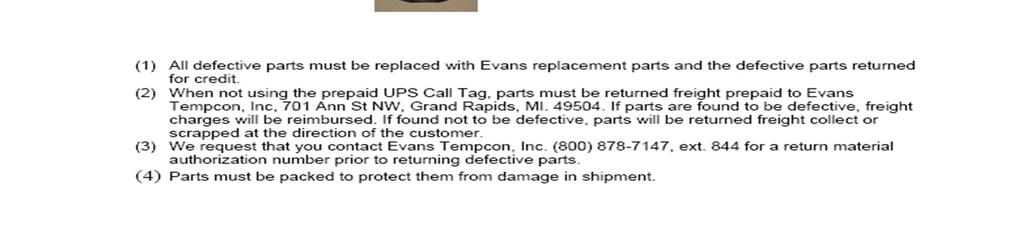
74 DEFECTIVE COMPONENTS NEED TO BE RETURNED 1. ALLOWS US TO TEST COMPONENTS FOR TYPE OF FAILURE AS WELL AS DETERMINE IF A FAILURE DID INDEED OCCUR. 2. ALLOWS US MONITOR OUR PRODUCT QUAILITY AND UPDATE OUR WARRANTY ANALYSIS RECORDS.
75
76 END OF WEBSITE PRESENTATION QUESTIONS ABOUT OUR WEBSITE?
77 PART 4 EVANS HVAC SYSTEM COMPONENTS


78 HVAC BASE UNIT INSTALLED TO FIRE WALL


79 HVAC BASE UNIT UNIT PART NUMBER LABEL REFRIGERANT CHARGE QUANTITY LABEL FRESH AIR INLETS


80 HVAC BASE UNIT FROST PREVENTION THERMOSTAT THERMOSTATIC EXPANSION VALVE HEATING COIL TUBES


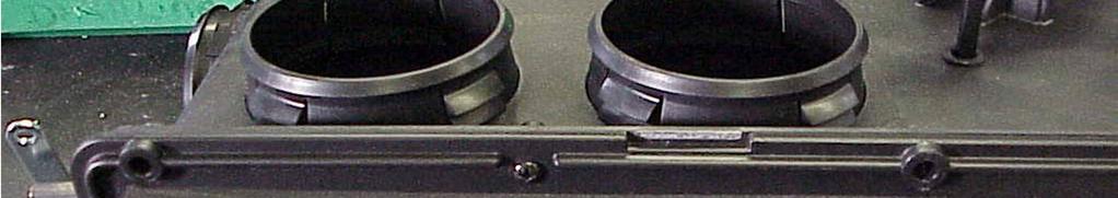
81 FIRE WALL SIDE OF HVAC BASE UNIT COMBINATION HEATING & COOLING COIL CAB RECIRCULATION INLET AIR DAMPER

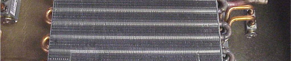
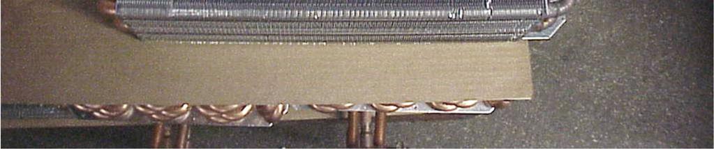
82 COMBINATION COOLING & HEATING COIL ½ FIN & TUBE


83 COOLANT / HEAT CONTROL VALVE ASSEMBLY Coolant Flow Control Valve Actuator Assembly Mounting Plate Slotted Ball Valve And Actuating Motor


84 COOLANT FLOW CONTROL VALVE Coolant Flow Direction Indicator Valve is directionally sensitive


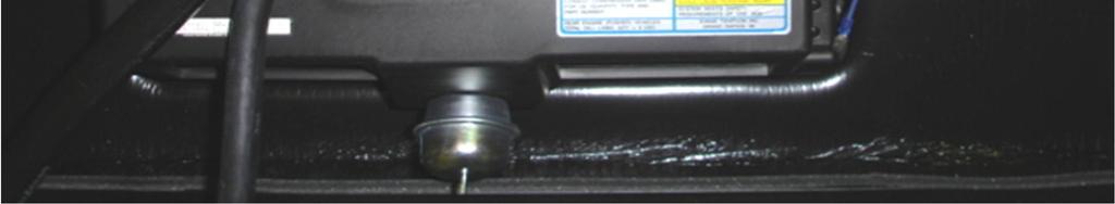
85 VACUUM SUPPLY - RESERVOIR BULB


")

86 VACUUM PUMP Black Wire (Grd) Red Wire (+12Vdc)


87 DASH CONTROL PANEL BLOWER SPEED SWITCH VENTILATION MODE SWITCH HEATING COIL COOLANT VALVE CONTROL


88 AIR DISTRIBUTION BOX / BLOWER ASSEMBLY AIR DISTRIBUTION BOX ASSSEMBLY BLOWER MOTOR ASSEMBLY

89 AIR DISTRIBUTION BOX ASSEMBLY DEFROST AIR OUTLET FLOOR AIR OUTLETS


90 AIR DISTRIBUTION BOX ASSEMBLY DEFROST / FLOOR VACUUM SHUTTER ACTUATOR DASH AIR OUTLETS FLOOR AIR OUTLETS DASH / FLOOR - VACUUM SHUTTER ACTUATOR


91 AIR DISTRIBUTION BOX ASSEMBLY FLOOR / DEFROST VACUUM SHUTTER ACTUATOR STICKERS MATCH VACUUM LINE COLOR
92 15-18 HG OF VACUUM FOR PROPER OPERATION


93 AIR DISTRIBUTION BOX ASSEMBLY DEFROST / FLOOR SHUTTER DASH / FLOOR SHUTTER BLOWER ASSEMBLY 4 SPEED RESISTOR


94 4 SPEED BLOWER RESISTOR Measure Voltage At The Resistor First. It Helps To Determine If the Problem Is Here Or At The Blower Speed Switch Or The Motor Itself.


95 REFRIGERANT LOW PRESSURE SWITCH


96 REFRIGERANT HIGH PRESSURE SWITCH
97 REFRIGERANT PRESSURE SWITCHES 1. LOW REFRIGERANT PRESSURE SWITCH THAT PREVENTS THE SUCTION OR LOW SIDE OF THE REFRIGERANT CIRCUIT FROM GOING INTO A VACUUM THUS POTENTIALLY HARMING THE COMPRESSOR. 2. HIGH REFRIGERANT PRESSURE SWITCH 3 TYPICAL TYPES A. SINGLE ONE FAULT SETTING B. BINARY TWO FAULT SETTINGS C. TRINARY THREE FAULT SETTINGS 3. HIGH REFRIGERANT PRESSURE SWITCH TYPICAL USES ARE: A. LOW REFRIGERANT CHARGE PROTECTION B. CONDENSER FAN CONTROL BY ENERGIZING CONDENSER FAN RELAY AT A PREDETERMINED HIGH PRESSURE SETTING C. COMPRESSOR PROTECTION BY DE-ENERGIZING THE COMPRESSOR CLUTCH AT A VERY HIGH PRESSURE SETTING.

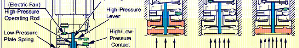
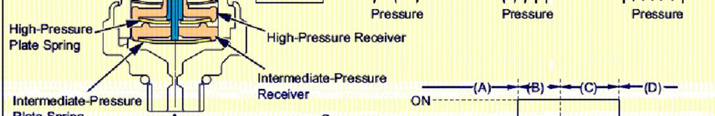
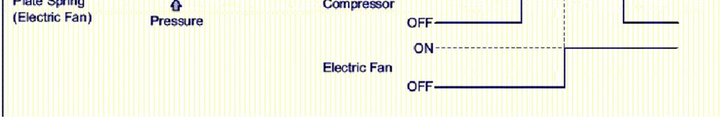
98 TRINARY OR TRIPLE REFRIGERANT PRESSURE SWITCH


99 TRINARY OR TRIPLE REFRIGERANT PRESSURE SWITCH LESS THAN 29 PSI ± 3 BOTH CONTACTS OPEN


100 TRINARY OR TRIPLE REFRIGERANT PRESSURE SWITCH OVER 29 PSI ± 3 COMPRESSOR CLUTCH CONTACTS CLOSE


101 TRINARY OR TRIPLE REFRIGERANT PRESSURE SWITCH OVER 228 PSI ± 21 ELECTRIC CONDENSER FAN CONTACTS CLOSE UNDER 185 PSI ± 21 FAN CONTACTS OPEN


102 TRINARY OR TRIPLE REFRIGERANT PRESSURE SWITCH OVER 385 PSI ± 29 COMPRESSOR CLUTCH CONTACTS OPEN UNDER 299 PSI ± 29 FAN CONTACTS CLOSE


103 FIN & TUBE CONDENSER W/ FAN ASSEMBLY Photo Album by Jim Wood


104 REMOTE MOUNTED PARALLEL FLOW CONDENSER W/ FAN ASSEMBLY


105 REMOTE MOUNTED PARALLEL FLOW CONDENSER W/ FAN ASSEMBLY
106 PART 5 A/C SYSTEM THEORY OF OPERATION
 or from the exterior of the vehicle (Fresh Air Inlet Mode) is sucked into the HVAC unit by an air flow moving device called")
107 HOW DOES THE AC SYSTEM OPERATE? Air from either the interior of the vehicle (Recirculation Air Inlet Mode) or from the exterior of the vehicle (Fresh Air Inlet Mode) is sucked into the HVAC unit by an air flow moving device called a blower assembly. The air flow passes through a heat absorbing coil called an evaporator located within the HVAC unit. The evaporator then transfers the heat from the air to a cool fluid medium called R134a refrigerant which is encapsulated within a plumbing network. The heated refrigerant is transferred by a pump or compressor into the engine compartment where it then rejects this heat to exterior air flow traveling through a heat rejection coil called a condenser. This is a continuous process that occurs whenever the compressor is operating.
 and calories.")
108 HOW IS HEAT TRANSFERRED? First we need to understand the fundamentals of heat. The amount of heat energy present in the air and refrigerant is measured as the temperature. There are two different temperature scales most commonly used are Fahrenheit and Celsius. Heat is measured in British Thermal Units (BTUs) and calories. BTU - amount of heat energy required to raise one pound of water one degree Fahrenheit. Calorie - amount of heat energy required to raise one gram of water one degree Celsius.
109 TYPES OF HEAT Sensible Heat: When the heat that is applied to a substance merely raises its temperature, but does not change its physical state. It is the heat which, added to or subtracted from a substance, produces the changes in temperature indicated on a thermometer. (i.e. It is the heat that you feel or sense) Latent Heat: The heat released or absorbed by a substance when it changes its physical state to another with no change in temperature. (i.e. ice to liquid and liquid to vapor) a) There are two forms of latent heat: 1) latent heat of fusion in the conversion of a liquid to a solid, or vice versa (i.e. The Freezing Point For water it is 32 F or 0 C). 2) latent heat of vaporization in the conversion of a liquid to a vapor, or vice versa. (i.e. The Boiling Point For water it is 212 F or 100 C). The latent heat of vaporization phenomenon is the founding principle in refrigeration and air conditioning. It is known as THE COOLING EFFECT!
110 HOW IS HEAT TRANSFERRED? An air conditioning system's efficiency is based on how well it moves heat. Heat Transfer is the method by which heat flows. Heat always travels from warm material to cold. The reverse is never true. For example, if a hot cup of coffee is left standing. it will cool off, while a cold soda will get warm. The heat from the warm coffee moves to the cooler surrounding air (i.e. condenser s heat rejection). The heat from the surrounding air moves to the cooler soda, until a balance is reached (i.e. evaporator s heat absorption).

 3.")

111 THREE PROCESS OF HEAT TRANSFER 1. Radiation: Heat moves from a heat source to an object by means of heat rays. For example, you feel heat from a fireplace, even though air is traveling past you and going up the chimney. You are warmed by radiated heat. (i.e. Engine compartment heat, body of the vehicle exposed to the sun, etc.) 2. Convection: Heat flows in a stream of air or liquid that is hotter than what it flows over, around, or through. For example, a blow dryer generates a stream of heated air to dry hair. The hair is heated by convection. (i.e. The inlet air of the HVAC unit scrubbing the aluminum fins of the evaporator or visa versa with the condenser) 3. Conduction: Heat travels along a material. For example, if a spoon is left in a pot of boiling water, the spoon handle will get hot, even though the handle is outside the pot. Heat is conducted along the spoon handle. (i.e. The heat in the coil s fins passing to the refrigerant passages & into the refrigerant)


112 HEAT TRANSFER DIAGRAM Sensible Heat which is not very efficient method of heat transfer A bigger bang for the buck! Sensible Heat The AC system creates the situation were the refrigerant is either boiling or condensing to provide the most efficient means of heat transfer.

113 THE ADDED VALUE OF LATENT HEAT TRANSFER R134a refrigerant is about one tenth less in latent heat value but is used instead of water because it boils at temperatures below the freezing point of water and at a higher pressure than atmospheric pressure. It has the needed characteristics to boil at a low temperature and is able to change its state readily from liquid to vapor, and vice versa.
114 HOW DOES THE AC SYSTEM CREATE THIS PHENOMENON? Pressure / temperature relationship: As the pressure on a liquid is increased, the boiling point rises. As the pressure on a liquid is decreased, the boiling point drops. In an air conditioning system, the refrigerant is contained in a closed loop plumbing system that can be pressurized. The pressure in the evaporator is low, so that all the refrigerant vaporizes. The pressure in the condenser is high, so that all the refrigerant readily changes state to a liquid. In an air conditioning system, a compressor is used to increase the pressure of the refrigerant; this raises its temperature. The refrigerant vapor entering the condenser is hot. In this air conditioning systems, an expansion valve is used to lower the pressure of the refrigerant; the refrigerant in the evaporator is cold. Automotive A/C Systems are designed to operate at pressures that keep the refrigerant at the optimum temperature for taking heat out of the passenger compartment.

115 TYPICAL OPERATING CONDITIONS AC system typically operates in a 50 F to 110 F environmental range. In those given conditions the AC operating pressures range from 5 to 30 psig on the evaporator side and 75 to 325 psig on the condenser side. This correlates in refrigerant temperature to - 2 F to 35 F on the evaporator side and 73 F to 166 F on the condenser side. In an 110 F environment, the air flowing through the evaporator is ~75 F hotter than the refrigerant and it boils and becomes a vapor. In an 110 F environment, the air flowing through the condenser is ~56 F cooler than the refrigerant and it condenses and becomes a liquid.


116 COMPRESSION SYSTEM USING THERMOSTATIC EXPANSION VALVE AS REFRIGERANT CONTROL 1. The compressor sucks in & compresses the cool R134a refrigerant gas, causing it to become hot, high pressure gas. 2. This hot gas runs through the condenser & dissipates its heat into its cooling air flow and condenses into a liquid. 3. The high pressure liquid enters the receiver/drier for storage and moisture removal. 4. The liquid is drawn off the bottom of the receiver/drier and runs through a pressure dividing, fixed size orifice hole in the thermostatic expansion valve. 5. A bulb containing R134a liquid refrigerant controls the flow of refrigerant by using a diaphragm to push down or retract a pin. The pin pushes downward onto small, metal ball plugging the orifice allowing liquid refrigerant to enter the evaporator. The ball is cradled by an upward, pushing spring to counter the pin s downward force and both forces modulate refrigerant flow through the AC system. 6. The low pressure liquid refrigerant travels through the coil and evaporates thus becoming cold, low pressure gas which absorbs heat from the hot air flowing through the coil. 7. A small amount of lightweight oil is mixed in with the refrigerant to lubricate the compressor.
 A/C system is fully charged.")
117 REFRIGERANT METERING VALVE OR THERMOSTATIC EXPANSION VALVE (TXV) FUNCTION TEST TXV Operation: The Thermostatic Expansion Valve or TXV is an interactive device that senses pressure and temperature then adjusts refrigerant flow to maintain a given superheat. Do not replace this device unless its function has been properly tested. TXV Function Test: 1) A/C system is fully charged. 2) Blower motor set for high speed. 3) Engage compressor and allow A/C system to stabilize. 4) After 5-10 minutes observe low side refrigerant operating pressures and record. 5) Change the blower motor speed to low and continue to watch the low side pressure. The pressure should drop ~3 4 Psig depending on the heat load in ~1 2 minutes. 6) Repeat this procedure 2 3 more times. 7) If the low side pressure can be influenced by changing the blower motor fan speed then the TXV is responding in the changing of the evaporator s heat load as designed. Refrigerant Flow
118 AC COMPRESSOR FUNCTION TEST A/C Compressor Operation: The A/C compressor is the heart of the system since it produces the refrigerant flow. Check to see if the compressor s clutch engaged or rotating and the compressor is operating by producing low and high side pressure ratios listed in the Estimated A/C Performance Chart. Compressor and engine fan belts should be in good condition and tightened to the correct tension. Check the belts when the engine is off the and the belt is still warm. Do not replace this compressor unless its function has been properly tested. A/C Compressor Function Test: 1) Restrict inlet air flow to the condenser with a piece of cardboard to increase high side refrigerant pressure. 2) Monitor high side pressure gauge to see if the pressure rises to ~ Psig. If the pressure does rise to this level then remove the cardboard. 3) This is a quick and simple test to see if the compressor has the capacity to build pressure and pump refrigerant. If it does not achieve that high pressure range then check the items below: 1) Low refrigerant charge. 2) High side refrigerant blockage. 3) Ambient temperature is below 50 F. 4) Clutch slippage or low voltage. 5) Inspect compressor front seal and pressure relief valve for leaks. 6) Clutch voltage should be ±11.5 Vdc. Clutch coil resistance between 2.2 and 4.4 ohms. 7) Check compressor rotation for smoothness.
119 END OF SERVICE PRESENTATION QUESTIONS?
Recreational Vehicle
 Evans Tempcon, Inc. Recreational Vehicle FRONT OCCUPANTS HVAC Service Manual (All Electric Control Systems) EVANS TEMPCON, INC. 701 ANN ST. NW GRAND RAPIDS, MI 49504 (616) 361-2681 WWW.EVANSTEMPCON.COM
GENERAL 2004 HVAC SYSTEMS. Manual HVAC System - Sorento SPECIFICATIONS. Fig. 1: Air Conditioner Specifications Courtesy of KIA MOTORS AMERICA, INC.
 Fig. 2: Blower & Evaporator Unit Specifications 2004 HVAC SYSTEMS Manual HVAC System - Sorento GENERAL SPECIFICATIONS AIR CONDITIONER Fig. 1: Air Conditioner Specifications BLOWER AND EVAPORATOR UNIT HEATER
A/C-HEATER SYSTEM - MANUAL
 A/C-HEATER SYSTEM - MANUAL 1986 Isuzu Trooper II 1986 A/C-HEATER SYSTEM Isuzu A/C-Heater Systems - Manual P UP, Trooper II * PLEASE READ THIS FIRST * CAUTION: When discharging air conditioning system,
Vehicle Level Heating and Air Conditioning Description and Operation A/C System - Manual. A/C System - Manual
 1 of 5 4/7/2008 8:32 AM Home Account Contact ALLDATA Log Out Help Select Vehicle New TSBs Technician's Reference Component Search: METRO TOYOTA OK 1999 Ford Truck F 450 2WD Super Duty V10-6.8L VIN S Vehicle
BC BRONCOS AIR CONDITIONING UNIT
 BC BRONCOS AIR CONDITIONING UNIT CAUTION If you are not familiar with the principals of air conditioning, have an authorized air conditioning technician evacuate and charge the system. Serious damage to
HEATING AND VENTILATION
 SECTION 14-102.04 14-102.04/ 1 2007OC19 DESCRIPTION The heating, ventilation and air conditioning (HVAC) system is designed to optimize passenger comfort. The system regulates interior vehicle atmosphere,
 Section 12-00: Climate Control System Service 1997 Town Car Workshop Manual DIAGNOSIS AND TESTING Procedure revision date: 06/29/2000 Climate Control System Inspection and Verification 1. Verify the customer's
EVANS TEMPCON DASH HEATER A/C All Electric Control Systems
 EVANS TEMPCON DASH HEATER A/C All Electric Control Systems Owner s Manual Operating Instructions For additional owner and operator information visit us on the web at www.evanstempcon.com WARNING This heater
Table of Contents. Table of Contents Introduction... Intro-1
 Table of Contents Table of Contents...1-3 Introduction... Intro-1 Chapter 1 Chapter 2 Chapter 3 Chapter 4 Chapter 5 Chapter 6 Chapter 7 Chapter 8 Chapter 9 Chapter 10 Chapter 11 Chapter 12 Air Conditioning
HEATING AND AIR CONDITIONING
 WJ HEATING AND AIR CONDITIONING 24-1 HEATING AND AIR CONDITIONING TABLE OF CONTENTS page SERVICE PROCEDURES REFRIGERANT OIL LEVEL...1 REFRIGERANT RECOVERY....1 REFRIGERANT SYSTEM CHARGE...1 REFRIGERANT
Performance Automotive Air Conditioning
 Performance Automotive Air Conditioning The Basics 18865 GOLL ST. - SAN ANTONIO, TX. - 78266 ph.210-654-7171 - fax 210-654-3113 The Basics of Performance Air Conditioning 1. Primary purpose of air conditioning
an ISO 9001:2015 Registered Company
 an ISO 9001:2015 Registered Company Mark IV (672001-VHY) 18865 Goll St. San Antonio, TX 78266 Phone: 800-862-6658 Sales: sales@vintageair.com Tech Support: tech@vintageair.com www.vintageair.com 902001-VHY
PERFECT FIT IN-DASH HEAT/ COOL/ DEFROST FORD PICKUP
 specializing in AIR CONDITIONING, PARTS AND SYSTEMS for your classic vehicle PERFECT FIT IN-DASH HEAT/ COOL/ DEFROST 1960-66 FORD PICKUP CONTROL & OPERATING INSTRUCTIONS The controls on your new Perfect
Room Air Conditioner Service and Parts Manual
 Cool Dry Temp Mode Room Air Conditioner Service and Parts Manual F Fan Speed hr Timer 0n 0ff Money Saver Fan Only Auto Swing Power CP06 CP08 93011401_01 CONTENTS 1. PREFACE 1.1 SAFETY PRECAUTIONS...2 1.2
MANUAL CONTROL HEATING, VENTILATION, AND AIR CONDITIONING SYSTEM
 SECTION 7B MANUAL CONTROL HEATING, VENTILATION, AND AIR CONDITIONING SYSTEM CAUTION: Disconnect the negative battery cable before removing or installing any electrical unit or when a tool or equipment
an ISO 9001:2008 Registered Company GOLL ST. - SAN ANTONIO, TX ph fax MINI SPACE SAVER HEAT /COOL
 an ISO 9001:2008 Registered Company 18865 GOLL ST. - SAN ANTONIO, TX. - 78266 - ph.210-654-7171 - fax 210-654-3113 MINI SPACE SAVER HEAT /COOL 01000-QUX-A 01000-VUX-A 900101-VUX-A REV C 3/5/14, MINI SPACE
Installation Instructions
 PAGE 1 Installation Instructions Important information about your new a/c system. Please read the following directions prior to installing this a/c system. PN: CK6772-1CHPU 1967-1972 Chevy PU A/C Kit Contact
AIR CONDITIONING. Carrier Corporation 2002 Cat. No
 AIR CONDITIONING Carrier Corporation 2002 Cat. No. 020-016 1. This refresher course covers topics contained in the AIR CONDITIONING specialty section of the North American Technician Excellence (NATE)
Heater with Air Conditioning. E-Series Ford Aeromaster
 Service Guide Heater with Air Conditioning E-Series Ford Aeromaster Contents Blower Motor...2 Plenum Removal...3 Control Module...6 Servo Motors...8 Coolant Valve and Servo Motor...8 Evaporator Recirculation
specializing in AIR CONDITIONING, PARTS AND SYSTEMS for your classic hi l PERFECT FIT SERIES IN-DASH HEAT/ COOL/ DEFROST FORD TRUCK
 specializing in AIR CONDITIONING, PARTS AND SYSTEMS for your classic hi l PERFECT FIT SERIES IN-DASH HEAT/ COOL/ DEFROST 1967-72 FORD TRUCK CONTROL & OPERATING INSTRUCTIONS The controls on your new Perfect
SECTION 7 AIR CONDITIONING (COOLING) UNIT 41 TROUBLESHOOTING
 UNIT 41 TROUBLESHOOTING") SECTION 7 AIR CONDITIONING (COOLING) UNIT 41 TROUBLESHOOTING UNIT OBJECTIVES After studying this unit, the reader should be able to Select the correct instruments for checking an air conditioning unit
SECTION 7 AIR CONDITIONING (COOLING) UNIT 41 TROUBLESHOOTING UNIT OBJECTIVES After studying this unit, the reader should be able to Select the correct instruments for checking an air conditioning unit
1956 FORD F-100 TRUCK
 an ISO 9001:2008 Registered Company INSTALLATION INSTRUCTIONS FOR 1956 FORD F-100 TRUCK HEAT/COOL/DEFROST 75456-LFZ-A 18865 GOLL ST. - SAN ANTONIO, TX. - 78266 - ph.210-654-7171 - fax 210-654-3113 905456-LFZ-A
Sleeper Heater and Air Conditioner, Blend Air System 83.05
 Sleeper Heater and Air Conditioner, Blend Air System 8.0 General Information General Description The sleeper heater and air conditioner assembly is mounted in either the baggage compartment or under the
Motor Vehicle Air Conditioning (MVAC) System operation and the refrigerant cycle
 System operation and the refrigerant cycle") Motor Vehicle Air Conditioning (MVAC) System operation and the refrigerant cycle At Sea level water boils at 212⁰ F R 134a boils at 15⁰ F At Sea level R 134a boils at 15⁰ F At 30 psig R 134a boils at 35⁰
Motor Vehicle Air Conditioning (MVAC) System operation and the refrigerant cycle At Sea level water boils at 212⁰ F R 134a boils at 15⁰ F At Sea level R 134a boils at 15⁰ F At 30 psig R 134a boils at 35⁰
Table of Contents. Service Procedures. Service Procedures. Measuring Superheat (4) Measuring Subcooling (5) Airflow Calculation (6-8)
 Measuring Subcooling (5) Airflow Calculation (6-8)") Table of Contents Refrigeration Cycle Service Procedures Measuring Superheat (4) Measuring Subcooling (5) Airflow Calculation (6-8) Solving Problems Identifying Low System Charge (9-11) Identifying High
Table of Contents Refrigeration Cycle Service Procedures Measuring Superheat (4) Measuring Subcooling (5) Airflow Calculation (6-8) Solving Problems Identifying Low System Charge (9-11) Identifying High
an ISO 9001:2008 Registered Company MINI SPACE SAVER HEAT /COOL/DEFROST QUZ-A VUZ-A
 an ISO 900:2008 Registered Company MINI SPACE SAVER HEAT /COOL/DEFROST 0000-QUZ-A 0000-VUZ-A 8865 GOLL ST. - SAN ANTONIO, TX. - 78266 - ph.20-654-77 - fax 20-654-33 90000-VUZ-A REV E 3/5/4, MINI SPACE
SERVICING PROCEDURE R-410A LEAK TEST EVACUATION CHARGING. Bard Manufacturing Company, Inc. Bryan, Ohio Manual Page 1 of 11
 SERVICING PROCEDURE R-410A LEAK TEST EVACUATION CHARGING Bard Manufacturing Company, Inc. Bryan, Ohio 43506 Since 1914...Moving ahead, just as planned. Manual No.: 2100-479 Supersedes: NEW File: Volume
BASIC HEAT PUMP THEORY By: Lloyd A. Mullen By: Lloyd G. Williams Service Department, York Division, Borg-Warner Corporation
 INTRODUCTION In recent years air conditioning industry technology has advanced rapidly. An important byproduct of this growth has been development of the heat pump. Altogether too much mystery has surrounded
T-SERIES Air Conditioner. T20 Model INSTRUCTION MANUAL nvent Rev. C P/N
 T-SERIES Air Conditioner T20 Model INSTRUCTION MANUAL Rev. C P/N 89114993 TABLE OF CONTENTS Warranty and Return Policy... 2 IMPORTANT NOTICE... 2 RECEIVING THE AIR CONDITIONER... 3 HANDLING AND TESTING
Cab Heater and Air Conditioner, Water-Valve Controlled 83.02
 Preliminary Checks Before testing the operation of the air conditioning system, make the following checks: 1. Make sure the drive belt on the refrigerant compressor is not damaged and is correctly tensioned.
COMPAC GEN II HEAT/COOL VUX-A. an ISO 9001:2008 Registered Company #10 SUCTION HOSE COMPRESSOR #8 DISCHARGE HOSE EVAPORATOR DRIER CONDENSER
 an ISO 900:2008 Registered Company COMPAC GEN II HEAT/COOL 68000-VUX-A EVAPORATOR #0 SUCTION HOSE COMPRESSOR #8 DISCHARGE HOSE DRIER #6 LIQUID LINE CONDENSER 90680-VUX-A REV E 2/28/4, INST. GEN II COMPAC
SPECTRACOOL Air Conditioner. N21 Model INSTRUCTION MANUAL nvent Rev. G P/N
 SPECTRACOOL Air Conditioner N21 Model INSTRUCTION MANUAL Rev. G P/N 89115088 TABLE OF CONTENTS WARRANTY AND RETURN POLICY...2 RECEIVING THE AIR CONDITIONER...3 HANDLING AND TESTING THE AIR CONDITIONER...3
PERFECT FIT SERIES IN-DASH HEAT/ COOL/ DEFROST CHEVROLET NOVA
 specializing in AIR CONDITIONING, PARTS AND SYSTEMS for your classic PERFECT FIT SERIES IN-DASH HEAT/ COOL/ DEFROST 1966-67 CHEVROLET NOVA CONTROL & OPERATING INSTRUCTIONS The controls on your new Perfect
SUPER GEN II HEAT/COOL VUX-A. an ISO 9001:2008 Registered Company EVAPORATOR #10 SUCTION HOSE COMPRESSOR #8 DISCHARGE HOSE DRIER CONDENSER
 an ISO 900:2008 Registered Company SUPER GEN II HEAT/COOL 6005-VUX-A EVAPORATOR #0 SUCTION HOSE COMPRESSOR #8 DISCHARGE HOSE DRIER #6 LIQUID LINE CONDENSER 90606-VUX-A REV E 2/28/4, INST. GEN II SUPER
Freightliner Refrigerator Troubleshooting Guide For (TJ18F) (TJ22F) (TJ18FP3)
 (TJ22F) (TJ18FP3)") www.dometic.com Freightliner Refrigerator Troubleshooting Guide For Before initiating troubleshooting, the following equipment is recommended: Multimeter, 20 gauge (min) wires to use as jumpers, and 12Vdc
www.dometic.com Freightliner Refrigerator Troubleshooting Guide For Before initiating troubleshooting, the following equipment is recommended: Multimeter, 20 gauge (min) wires to use as jumpers, and 12Vdc
DOLE REFRIGERATING COMPANY 1420 Higgs Road Lewisburg, Tennessee Phone (931)
") DOLE REFRIGERATING COMPANY 1420 Higgs Road Lewisburg, Tennessee 37091 Phone (931) 359-6211 1-800-251-8990 www.doleref.com PHO WATER DEFROST OPERATION & MAINTENANCE MANUAL June 2002 PHO WATER DEFROST Table
DOLE REFRIGERATING COMPANY 1420 Higgs Road Lewisburg, Tennessee 37091 Phone (931) 359-6211 1-800-251-8990 www.doleref.com PHO WATER DEFROST OPERATION & MAINTENANCE MANUAL June 2002 PHO WATER DEFROST Table
T-Series Air Conditioner T15 Model
 INSTRUCTION MANUAL T-Series Air Conditioner T15 Model Protecting Electronics. Exceeding Expectations. McLean Cooling Technology 11611 Business Park Blvd N Champlin, MN 55316 USA Tel 763-323-8200 Fax 763-576-3200
1998 Expedition/Navigator Workshop Manual
 Page 1 of 8 SECTION 412-00: Climate Control System - General Information 1998 Expedition/Navigator Workshop Manual DESCRIPTION AND OPERATION Procedure revision date: 02/11/2000 Climate Control System WARNING:
VACUUM TROUBLESHOOTING GUIDE FOR EVANS TEMPCON HEATER-A/C SYSTEMS
 1 Air flow comes from defrost louvers regardless of mode selected. * Vacuum supply line to control panel has fallen off of vacuum reservoir. * Manifold vacuum supply Hose has fallen off at vacuum reservoir
PROAIR Air Conditioner. CR23 Model INSTRUCTION MANUAL nvent Rev. D P/N
 PROAIR Air Conditioner CR23 Model INSTRUCTION MANUAL Rev. D P/N 89112522 TABLE OF CONTENTS Warranty and Return Policy...2 RECEIVING THE AIR CONDITIONER...3 HANDLING AND TESTING THE AIR CONDITIONER...3
PERFECT FIT IN-DASH HEAT/ COOL/ DEFROST 1968 CHEVROLET IMPALA
 specializing in AIR CONDITIONING, PARTS AND SYSTEMS for your classic vehicle PERFECT FIT IN-DASH HEAT/ COOL/ DEFROST 1968 CHEVROLET IMPALA CONTROL & OPERATING INSTRUCTIONS The controls on your new Perfect
PERFECT FIT IN-DASH HEAT/ COOL/ DEFROST PLYMOUTH BELVEDERE
 PERFECT FIT IN-DASH HEAT/ COOL/ DEFROST 1966-67 PLYMOUTH BELVEDERE CONTROL & OPERATING INSTRUCTIONS The controls on your new Perfect Fit system. Offers complete comfort capabilities in virtually every
OPERATION & MAINTENANCE MANUAL TC670
 OPERATION & MAINTENANCE MANUAL TC670 Refrigerant Management Center (Convertible For Use With R12 or R134a) RTI TECHNOLOGIES, INC. 4075 East Market Street York, PA 17402 Manual P/N 035-80342-02 TC670 CONVERTIBLE
HEAT/ COOL/ DEFROST FORD THUNDERBIRD
 specializing in AIR CONDITIONING, PARTS AND SYSTEMS for your classic vehicle PERFECT FIT IN-DASH HEAT/ COOL/ DEFROST 1964-66 FORD THUNDERBIRD CONTROL & OPERATING INSTRUCTIONS The controls on your new Perfect
PERFECT FIT IN-DASH HEAT/ COOL/ DEFROST EARLY 1955 CHEVROLET PICKUP
 specializing in AIR CONDITIONING, PARTS AND SYSTEMS for your classic vehicle PERFECT FIT IN-DASH HEAT/ COOL/ DEFROST 1947 - EARLY 1955 CHEVROLET PICKUP CONTROL & OPERATING INSTRUCTIONS The controls on
CONTENTS. Air Conditioning Fundamentals TC S
 LEVEL F Air Conditioning Fundamentals SG Mazda Motor Corporation Technical Service Training CONTENTS 1 INTRODUCTION Overview... 1 Audience and Purpose... 1 Content and Objectives... 2 How to Use This Guide...
T-Series Air Conditioner T20 Model
 INSTRUCTION MANUAL T-Series Air Conditioner T20 Model Protecting Electronics. Exceeding Expectations. McLean Cooling Technology 11611 Business Park Blvd N Champlin, MN 55316 USA Tel 763-323-8200 Fax 763-576-3200
PROAIR Air Conditioner. CR29 Model INSTRUCTION MANUAL nvent Rev. I P/N
 PROAIR Air Conditioner CR29 Model INSTRUCTION MANUAL Rev. I P/N 89104461 TABLE OF CONTENTS Warranty and Return Policy...2 RECEIVING THE AIR CONDITIONER...3 HANDLING AND TESTING THE AIR CONDITIONER...3
SECTION 8 AIR SOURCE HEAT PUMPS UNIT 43 AIR SOURCE HEAT PUMPS
 SECTION 8 AIR SOURCE HEAT PUMPS UNIT 43 AIR SOURCE HEAT PUMPS UNIT OBJECTIVES After studying this unit, the reader should be able to Describe the operation of reverse-cycle refrigeration (heat pumps) Explain
To accomplish this, the refrigerant fi tis pumped throughh aclosed looped pipe system.
 Basics Refrigeration is the removal of heat from a material or space, so that it s temperature is lower than that of it s surroundings. When refrigerant absorbs the unwanted heat, this raises the refrigerant
Climate Control System
 Page 1 of 13 SECTION 412-00: Climate Control System General Information DESCRIPTION AND OPERATION 1998 Mark VIII Workshop Manual Climate Control System Cautions and Warnings WARNING: To avoid accidental
PERFECT FIT SERIES IN-DASH HEAT/ COOL/ DEFROST MUSTANG
 specializing in AIR CONDITIONING, PARTS AND SYSTEMS for your classic vehicle PERFECT FIT SERIES IN-DASH HEAT/ COOL/ DEFROST 1965-66 MUSTANG CONTROL & OPERATING INSTRUCTIONS The controls on your new Perfect
PERFECT FIT SERIES IN-DASH HEAT/ COOL/ DEFROST CHEVROLET CHEVELLE/ EL CAMINO NOTE: INSTRUCTIONS DEPICT CHEVELLE
 specializing in AIR CONDITIONING, PARTS AND SYSTEMS for your classic vehicle PERFECT FIT SERIES IN-DASH HEAT/ COOL/ DEFROST 1964-65 CHEVROLET CHEVELLE/ EL CAMINO NOTE: INSTRUCTIONS DEPICT CHEVELLE CONTROL
2004 HVAC. Heating, Ventilation and Air Conditioning - Hummer H2. Fastener Tightening Specifications Specification Application
 SPECIFICATIONS 2004 HVAC Heating, Ventilation and Air Conditioning - Hummer H2 FASTENER TIGHTENING SPECIFICATIONS Fastener Tightening Specifications Specification Application Metric English A/C Accumulator
Math. The latent heat of fusion for water is 144 BTU s Per Lb. The latent heat of vaporization for water is 970 Btu s per Lb.
 HVAC Math The latent heat of fusion for water is 144 BTU s Per Lb. The latent heat of vaporization for water is 970 Btu s per Lb. Math F. to C. Conversion = (f-32)*(5/9) C. to F. Conversion = C * 9/5 +
UNITED STATES MARINE CORPS ENGINEER EQUIPMENT INSTRUCTION COMPANY MARINE CORPS DETACHMENT 686 MINNESOTA AVE FORT LEONARD WOOD, MISSOURI
 UNITED STATES MARINE CORPS ENGINEER EQUIPMENT INSTRUCTION COMPANY MARINE CORPS DETACHMENT 686 MINNESOTA AVE FORT LEONARD WOOD, MISSOURI 65473-8963 LESSON PLAN AIR CONDITIONING SYSTEMS NCOM-F01 ENGINEER
PROAIR Air Conditioner. CR43 Model INSTRUCTION MANUAL nvent Rev. H P/N
 PROAIR Air Conditioner CR43 Model INSTRUCTION MANUAL Rev. H P/N 10-1008-130 TABLE OF CONTENTS Warranty and Return Policy...2 RECEIVING THE AIR CONDITIONER...3 HANDLING AND TESTING THE AIR CONDITIONER...3
HEATING AND AIR CONDITIONING
 PL HEATING AND AIR CONDITIONING 24-1 HEATING AND AIR CONDITIONING CONTENTS page GENERAL INFORMATION INTRODUCTION... 2 SAFETY PRECAUTIONS AND WARNINGS... 2 DESCRIPTION AND OPERATION A/C REFRIGERANT LINES...
MINI SLIMLINE COOL VUY-A VUY-A
 an ISO 900:2008 Registered Company MINI SLIMLINE COOL 030-VUY-A 040-VUY-A 8865 GOLL ST. - SAN ANTONIO, TX. - 78266 ph.20-654-77 - fax 20-654-33 900302 REV D 0/28/4, MINI SLIMLINE COOL PG OF Table of Contents
Installation Manual for ETI AVS Series and NON-ETI Air Handlers with SC or SD Compressor Units and R-410A Refrigerant
 EarthLinked TXV Kit Installation Manual for ETI AVS Series and NON-ETI Air Handlers with SC or SD Compressor Units and R-410A Refrigerant CONTENTS PAGE Pre-Installation 3 Air Handler Conversion 4 System
EBAC MODEL CD30 INDUSTRIAL DEHUMIDIFIER OWNER S MANUAL
 EBAC MODEL CD30 INDUSTRIAL DEHUMIDIFIER OWNER S MANUAL Ebac Industrial Products 704 Middle Ground Boulevard Newport News, VA 23606 Tel: 757 873 6800 Fax: 757 873 3632 Website: www.ebacusa.com UNPACKING
TOYOTA FJ-40 DIRECTIONS
 PAGE 1 TOYOTA FJ-40 DIRECTIONS Please read the following directions prior to installing this a/c system. Contact us by email or phone if you need any assistance or information regarding this a/c system.
T-SERIES Air Conditioner. T50 Model INSTRUCTION MANUAL nvent Rev. F P/N
 T-SERIES Air Conditioner T50 Model INSTRUCTION MANUAL Rev. F P/N 10-1008-203 TABLE OF CONTENTS Warranty and Return Policy...2 RECEIVING THE AIR CONDITIONER...3 HANDLING AND TESTING THE AIR CONDITIONER...3
CIRRUS AIRPLANE MAINTENANCE MANUAL
 COOLING 1. DESCRIPTION On aircraft serials 183 and subsequent, an optional air condition system is available. This section contains the maintenance practices pertinent to this system. Cabin ventilation
EBAC MODEL WM150 INDUSTRIAL DEHUMIDIFIER OWNER S MANUAL
 EBAC MODEL WM150 INDUSTRIAL DEHUMIDIFIER OWNER S MANUAL WM150 OWNERS MANUAL Page 1 of 9 INTRODUCTION Designed for a wide range of applications, the WM150 is a rugged, industrial unit, which utilizes an
ENSPECO Recovery/ Recycle/ Evacuate/ Recharge
 ENSPECO Recovery/ Recycle/ Evacuate/ Recharge RMS 3012 RMS 3034 Approved by UL/SAE to J-1991 R12 Purity Standards Approved by UL/SAE to J-2210 R134 Purity Standards This semi-automatic machine will recover
RTP Technical Bulletin
 RTP Technical Bulletin Category: REFRIGERATION REGISTERED TECHNICIANS PROGRAM Volume 1 Bulletin 2 the information contained in this bulletin contains some important c o n c e p t s regarding pressure/
Refrigeration Systems and Accessories
 As with the Chapter Review Tests and the Final Exam, the tests your understanding of the materials underlying the learning objectives. After you ve reviewed your answers to the Chapter Review Tests, try
Condensing Unit Installation and Operating Instructions
 Bulletin WCU_O&I 01 June 2003 Condensing Unit Installation and Operating Instructions WCU Air Cooled Condensing Unit Table of Contents Section 1. Section 2. Section 3. Section 4. Section 5. Section 6.
347002K/177002K/34900
 Service Manual Models: 347002K/177002K 34900/347012K Manifold Block Style Recovery/Recycling/Recharging Unit For R-12 or R-134a Only TABLE OF CONTENTS: Theory of Operation and Safety Precautions... 2 Depressurizing
T-Series Air Conditioner T53 Model
 INSTRUCTION MANUAL T-Series Air Conditioner T53 Model Protecting Electronics. Exceeding Expectations. McLean Cooling Technology 11611 Business Park Blvd N Champlin, MN 55316 USA Tel 763-323-8200 Fax 763-576-3200
WELCH INDUSTRIES - PAGE 1 OF 5
 MCI 9, 96A & 102 RE-2 Auxiliary Installation Look over all components in order to familiarize yourself with the complete system. The compressor mounts over the gear-box between radiators, driven by the
Calhoon MEBA Engineering School. Study Guide for Proficiency Testing Refrigeration
 Calhoon MEBA Engineering School Study Guide for Proficiency Testing Refrigeration 1. To prevent an injury when working with refrigerants, what safety precautions are necessary? 2. When halogens are in
Refrigerant Recovery Unit, Model RRU134
 Installation, Operation & Maintenance Manual IOMM RRU134 Group: Refrigerant Effective: December 2000 Supersedes: New Refrigerant Recovery Unit, Model RRU134 1999 McQuay International Table of Contents
SECTION 50 - CAB CLIMATE CONTROL
 AIR CONDITIONING SYSTEM DYNAMIC DESCRIPTION The refrigerant circuit of the air conditioning system contains five major components: Compressor, Condenser, Receiver/Drier, Expansion Valve, and Evaporator.
Harold Ag & Mobile Products
 TM Harold Ag & Mobile Products Your Ag A/C Parts Specialist 1-800-541-8910 www.heco.net R E F R I G E R A N T S 6-18-13 FR-12 COMPARED TO OTHER BLENDS UL Classified A1/A1 (non-flammable!) ASHRAE Listed
Air Conditioning Components
 Air Conditioning Components Agenda AC Components Compressor & Clutch Condenser Receiver-drier or Accumulator Expansion Valve or Orifice Tube Evaporator Compressor 2 primary purposes Increase pressure &
B. A. T. Basic Appliance Training
 B. A. T. Basic Appliance Training BASIC REFRIGERATION presented by Phil Whitehead Program Objective The objective of this program is to give you some of the basic elements that are essential to understanding
GENESIS Air Conditioners. All Models INSTRUCTION MANUAL nvent Rev. K P/N
 GENESIS Air Conditioners All Models INSTRUCTION MANUAL Rev. K P/N 89104462 TABLE OF CONTENTS Warranty and Return Policy...2 RECEIVING THE AIR CONDITIONER...3 HANDLING AND TESTING THE AIR CONDITIONER...3
SECTION 5 COMMERCIAL REFRIGERATION UNIT 21 EVAPORATORS AND THE REFRIGERATION SYSTEM UNIT OBJECTIVES 3/22/2012 REFRIGERATION
 SECTION 5 COMMERCIAL REFRIGERATION UNIT 21 EVAPORATORS AND THE REFRIGERATION SYSTEM UNIT OBJECTIVES After studying this unit, the reader should be able to Define high-, medium-, and low-temperature refrigeration.
For an administrative fee of $9.97, you can get an un-locked, printable version of this book.
 The System Evaluation Manual and Chiller Evaluation Manual have been revised and combined into this new book; the Air Conditioning and Refrigeration System Evaluation Guide. For an administrative fee of
SERVICE PROCEDURE FOR RETROFITTED A/C SYSTEMS
 Classification: Reference: Date: HA94-005 NTB94-091 September 26, 1994 SERVICE PROCEDURE FOR RETROFITTED A/C SYSTEMS APPLIED VEHICLE(S): All models except Quest equipped with a retrofitted A/C system SERVICE
Electrical Problems. Fuse(s) blow or circuit breaker trips. Does the unit use circuit breakers or fuses? Replace with correct fuse(s)
 blow or circuit breaker trips. Does the unit use circuit breakers or fuses? Replace with correct fuse(s)") Electrical Problems Fuse(s) blow or circuit breaker trips Does the unit use circuit breakers or fuses? Fuse(s) Circuit breakers Are the fuses dual element time delay? Is the circuit breaker HACR rated?
Electrical Problems Fuse(s) blow or circuit breaker trips Does the unit use circuit breakers or fuses? Fuse(s) Circuit breakers Are the fuses dual element time delay? Is the circuit breaker HACR rated?
CHEST FREEZER INSTRUCTION MANUAL. Model No.: EWCF5WBX EWCF7WBX
 CHEST FREEZER INSTRUCTION MANUAL Model No.: EWCF5WBX EWCF7WBX To ensure proper use of this appliance and your safety, please read the following instructions completely before operating this appliance.
WMHP Series R410a Heat Pump INSTALLATION INSTRUCTIONS
 WMHP Series R410a Heat Pump INSTALLATION INSTRUCTIONS **WARNING TO INSTALLER, SERVICE PERSONNEL AND OWNER** Altering the product or replacing parts with non authorized factory parts voids all warranty
Room Air Conditioner CP06 & CP08. Chill 115 Volts. Service & Parts Manual THE EXPERTS IN ROOM AIR CONDITIONING _02
 Room Air Conditioner Service & Parts Manual 2014-2015 CP06 & CP08 Chill 115 Volts THE EXPERTS IN ROOM AIR CONDITIONING 93011401_02 CONTENTS 1. PREFACE 1.1 SAFETY PRECAUTIONS...2 1.2 INSULATION RESISTANCE
Room Air Conditioner SERVICE MANUAL MODEL : LW6013ERY3. CAUTION
 www.zenithappliances.com Room Air Conditioner SERVICE MANUAL MODEL : LW6013ERY3 CAUTION BEFORE SERVICING THE UNIT, READ THE SAFETY PRECAUTIONS IN THIS MANUAL. ONLY FOR AUTHORIZED SERVICE PERSONNEL. CONTENTS
WB Holden Aircondtioning Re-Instalation
 WB Holden Aircondtioning Re-Instalation My Ute has the rudimentary remains of the Airconditioning System in the form of the Evaporator/Heater airbox mounted forward and aft of the firewall. The original
RED DOT UNITS. Heating & Air Conditioning. Parts
 Heating & Air Conditioning Parts 71 R-134a COMPONENTS THE DETAILS R-134a is the new refrigerant that will be used in future heavy duty air conditioning systems. This new refrigerant is used in conjunction
Service Step by Step Trouble-Shooting Check-List
 WARNING: Only Data Aire trained technician or experience technicians should be working on Data Aire Equipment. Protect yourself at all times and work safe. Date: Dates at the job site: From: to Job#: Serial#:
Mortex INSTALLATION INSTRUCTIONS AIR CONDITIONING & HEAT PUMP INDOOR COILS
 Mortex INSTALLATION INSTRUCTIONS AIR CONDITIONING & HEAT PUMP INDOOR COILS INTRODUCTION Please note that HUD Manufactured Home Construction and Safety Standard Section 3280.714, paragraph (a) and subparagraph
T-SERIES Air Conditioner. T43 Model INSTRUCTION MANUAL nvent Rev. I P/N
 T-SERIES Air Conditioner T43 Model INSTRUCTION MANUAL Rev. I P/N 10-1008-145 TABLE OF CONTENTS Warranty and Return Policy...2 IMPORTANT NOTICE...2 RECEIVING THE AIR CONDITIONER...3 HANDLING AND TESTING
Operation and Maintenance Manual
 Warranty Information Ritchie Engineering guarantees YELLOW JACKET products to be free of defective material and workmanship which could affect the life of the product when used for the purpose for which
RecoverX Oil-Filled Hermetic Refrigerant Recovery System. Operation and Maintenance Manual
 RecoverX Oil-Filled Hermetic Refrigerant Recovery System Operation and Maintenance Manual Table of Contents Page General Safety Instructions 2-3 System Overview 3 Operating Guide 4 Restart Procedure 4
Rev B, 9/2/2009. Kodiak Chiller Overview
 930-0001 Rev B, 9/2/2009 Kodiak Chiller Overview Presentation Outline Phone: 781-933-7300 Lytron Technical Support Contact Information 3 Introduction 4 Part I: Unpacking 5 Part II: Installation 7 Part
SEA FROST BD 12 OR 24-VOLT D.C. AIR-COOLED SYSTEM
 148 OLD CONCORD TURNPIKE BARRINGTON, NH 03825 USA TEL (603) 868-5720 FAX (603) 868-1040 1-800-435-6708 E-Mail:sales@seafrost.com www.seafrost.com SEA FROST BD 12 OR 24-VOLT D.C. AIR-COOLED SYSTEM CONDENSING
RSES Technical Institute Training Manual 1 70 hours, 70 NATE CEHs, 7.2 CEUs
 Lesson 1 - Introduction to Refrigeration and Air Conditioning Define refrigeration. Identify the basic components of a refrigeration cycle. Identify the various gas laws and their importance to a basic
T-SERIES Air Conditioner. T29 Model INSTRUCTION MANUAL nvent Rev. I P/N
 T-SERIES Air Conditioner T29 Model INSTRUCTION MANUAL Rev. I P/N 89104464 TABLE OF CONTENTS Warranty and Return Policy...2 IMPORTANT NOTICE...2 RECEIVING THE AIR CONDITIONER...3 HANDLING AND TESTING THE
Refrigerant Recovery Machine. Model No Operating Manual
 Refrigerant Recovery Machine Model No. 25700 Operating Manual Safety Precautions WARNING : TO PREVENT PERSONAL INJURY AND / OR EQUIPMENT DAMAGE, CAUTION - Risk of injury. This equipment should only be
MASS. MARITIME ACADEMY
 MASS. MARITIME ACADEMY REFRIGERATION LAB OUTLINE Rev.3 Fall 2015 Table of Content Page Lab #1: Introduction to refrigeration system components, tools and procedures 1 Lab #2: Familiarization, operation,