Burners. Self-recuperative burners high speed free flame REKO-SIK-NxT-FF (E3901FN rev /02/2018)
|
|
|
- Domenic Weaver
- 5 years ago
- Views:
Transcription
1 Burners Self-recuperative burners high speed free flame REKO-SIK-NxT-FF (E3901FN rev /02/2018)
2 GENERAL WARNINGS: DISPOSAL: ¾ All installation, maintenance, ignition and setting must be performed by qualified staff, respecting the norms present at the time and place of the installation. ¾ To avoid damage to people and things, it is essential to observe all the points indicated in this handbook. The reported indications do not exonerate the Client/User from observing general or specific laws concerning accidents and environmental safeguarding. ¾ The operator must wear proper DPI clothing (shoes, helmets...) and respect the general safety, prevention and precaution norms. ¾ To avoid the risks of burns or high voltage electrocution, the operator must avoid all contact with the burner and its control devices during the ignition phase and while it is running at high temperatures. ¾ All ordinary and extraordinary maintenance must be performed when the system is stopped. ¾ To assure correct and safe use of the combustion plant, it is of extreme importance that the contents of this document be brought to the attention of and be meticulously observed by all personnel in charge of controlling and working the devices. ¾ The functioning of a combustion plant can be dangerous and cause injuries to persons or damage to equipment. Every burner must be provided with certified combustion safety and supervision devices. ¾ The burner must be installed correctly to prevent any type of accidental/undesired heat transmission from the flame to the operator or the equipment. ¾ The performances indicated in this technical document regarding the range of products are a result of experimental tests carried out at ESA-PYRONICS. The tests have been performed using ignition systems, flame detectors and supervisors developed by ESA-PYRO- NICS. The respect of the above mentioned functioning conditions cannot be guaranteed if equipment, which is not present in the ESA-PYRONICS catalogue, is used. To dispose of the product, abide by the local legislations regarding it. Esa S.p.A. Via Enrico Fermi Curno (BG) - Italy Tel Fax esa@esacombustion.it GENERAL NOTES: ¾ In accordance to the internal policy of constant quality improvement, ESA-PYRONICS reserves the right to modify the technical characteristics of the present document at any time and without warning. ¾ It is possible to download technical sheets which have been updated to the latest revision from the website. ¾ The REKO-SIK-NxT-FF products have been designed, manufactured and tested according to the most correct construction practices and following the applicable requirements described in UNI EN Industrial heating process equipment - Part 2: Safety requirements for combustion and for the handling and processing of fuels. We emphasize that the burners described in this data sheet are provided as independent units and are excluded from the scope of the Machine Directive 2006/42/EC not having any mobile items that are not exclusively manual. ¾ Certified in conformity with the UNI EN ISO 9001 Norm by DNV GL. CERTIFICATIONS: The products conform to the requests for the Euroasia market (Russia, Belarus and Kazakhstan). CONTACTS / SERVICE: ESA Belgium Zoning Industriel, 4ème rue B-6040 Jumet - Belgium Tel Fax marketing@pyronics.be 2


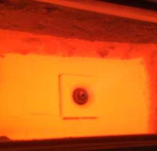
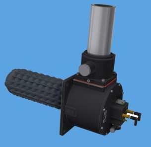
3 REKO-SIK-NxT-FF are self-recuperative gas burners for direct heating. These burners use combustive fumes to preheat the combustive air. Depending on size and conditions of use, this type of burner guarantees a substantial reduction in consumption compared to traditional burners. APPLICATIONS ¾Furnaces with fibre covering. ¾Ceramic or treatment furnaces. ¾Tunnel or chariot furnaces. ¾Furnaces with continuous or discontinuous function. ¾Furnaces with pulse-firing burner control. F3901FNI03 CHARACTERISTICS GENERAL: ¾Capacity: from 30 to 400 kw ¾Functions with various types of gas: CH4/LPG/Propane/etc. ¾Maximum furnace temperature: 1350 C ¾Burner inlet air pressure: 70 mbar ¾Burner inlet gas pressure: 70 mbar ¾Inlet air temperature: environment ¾Preheated air temperature: up to 750 C ¾Potential ratio: 1:5 ¾Flame velocity: up to 140 m/s ¾Low NOx e CO emission MATERIAL COMPOSITION: ¾Exhaust air-inlet body: ¾Gas collector pipe: ¾Exchange tube: ¾Combustion head: ¾Exhaust guiding spacer: Cast Iron G25 Cast Iron G25 AD-SIC INCOLOY601/AISI310S customized F3901FNI04 3
4 CAPACITY AND FLAME LENGTH PARAMETERS The REKO-SIK-NxT-FF ignition takes place through a high tension discharge, which is carried out by a WAND electrode. The flame is detected via a uv-scanner (not included). The adoption of flame controls is highly recoended in all systems operating at temperatures below 750 C (UNI EN746-2 Norm). Model Capacity kw Flame length Nozzle velocity output a 0m a 0,5m a 1m a 1,5m a 2m a 2,5m a 3m DESCRIPTION Ignition Detection REKO-30-SIK-NxT-FF WAND-EN WAND-EN/UV-2 REKO-70-SIK-NxT-FF WAND-EN WAND-EN/UV-2 REKO-120-SIK-NxT-FF WAND-EN WAND-EN/UV-2 REKO-170-SIK-NxT-FF WAND-EN WAND-EN/UV-2 REKO-240-SIK-NxT-FF WAND-EN WAND-EN/UV-2 REKO-400-SIK-NxT-FF WAND-EN WAND-EN/UV-2 The REKO-SIK-NxT-FF burners use the temperature exhaust fumes to preheat the combustive air, thus saving more energy and reducing atmospheric pollution. EXHAUST TOTAL AIR INLET FLUE GAS RECIRCULATION GAS INLET D3901FN01 The choice of materials has been made according to the burners performance. Furthermore, the stainless steel exhaust-air inlet body, assures a high resistance to heat and oxidation. The heat exchanger element is made of silicon carbide and its special conformation allows the optimization of heat transfer from the combustion products to the combustive air. This choice allows the burner to be used with maximum chamber temperature of up to 1300 C under direct heating conditions. 4
5 Multistage combustion technology, together with the recycling of combustive gases, guarantees low NOx and CO emissions, despite the preheating air temperature value of up to 750 C. The REKO-SIK-NxT-FF are compact burners with reduced weight and size. They have separate gas and air inlets, nozzle mixers (no flashbacks) and The flame capacity, length and velocity concern natural gas burners (8600 Kcal/Nm 3 ), placed in a combuinclude: micrometric gas adjuster, spark electrode, peep sight, gas calibrated orifice flow meter, furnace wall spacer and flue gas ejector. The suggested functioning is with MIN/MAX or ON/OFF and the setting is simplified by special pressure inlets on the air and gas side. BURNER PERFORMANCES stion chamber with zero pressure and at sea level, which can function with 10% of excess air. ¾MIN/MAX (ON/OFF) functioning ¾Chamber temperature 1100 C ¾NOx < 350 mg/nm 3 [O 2 = 3% ref.] MAXIMUM CAPACITY Maximum power Free flame application Burner model REKO-30 REKO-70 REKO-120 REKO-170 REKO-240 REKO-400 SiC recuperator length [] Burner capacity (2% O 2 ) [kw] Burner air flow [Nm 3 /h] Ejector air flow [Nm 3 /h] Total air flow (burner air + ejector air) [Nm 3 /h] Gas flow [Nm 3 /h] Burner air inlet pressure [mbar] p flange gas measurement [mbar] MINIMUM CAPACITY Minimum power Free flame application Burner model REKO-30 REKO-70 REKO-120 REKO-170 REKO-240 REKO-400 Burner capacity (2% O 2 ) [kw] Burner air flow [Nm 3 /h] Ejector air flow [Nm 3 /h] Total air flow (burner air + ejector air) [Nm 3 /h] Gas flow [Nm 3 /h] Burner air inlet pressure [mbar] p flange gas measurement [mbar]
6 EFFICIENCY TABLES Permanent operation (100% Fire) Furnace Temperature [ C] REKO-30-SIK-NxT-FF REKO-70-SIK-NxT-FF REKO-120-SIK-NxT-FF REKO-170-SIK-NxT-FF REKO-240-SIK-NxT-FF REKO-400-SIK-NxT-FF Efficiency [%] G3901FN01 Permanent operation (100% Fire) Furnace Temperature [ C] REKO-30-SIK-NxT-FF REKO-70-SIK-NxT-FF REKO-120-SIK-NxT-FF REKO-170-SIK-NxT-FF REKO-240-SIK-NxT-FF REKO-400-SIK-NxT-FF Flue Gas Temperature [ C] G3901FN02 6
7 EFFICIENCY TABLES Permanent operation (100% Fire) Furnace Temperature [ C] REKO-30-SIK-NxT-FF REKO-70-SIK-NxT-FF REKO-120-SIK-NxT-FF REKO-170-SIK-NxT-FF REKO-240-SIK-NxT-FF REKO-400-SIK-NxT-FF Preheated air [ C] G3901FN03 7
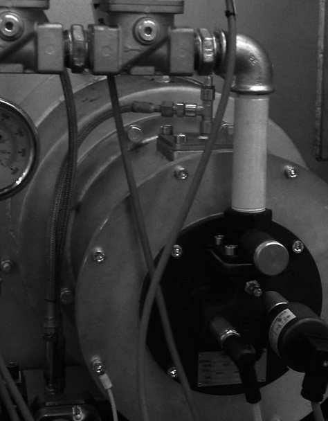
8 FLOW SCHEME - FREE FLAME BURNER FLUE GAS OUTLET AIR ADJUSTING VALVE 11 GAS INLET AIR INLET D3901FN02 Pos. Description Included Not Included 1 Gas ball valve x 2 Gas calibrated flange x 3 Pressure regulator x 4 Safety solenoid valve x 5 Throttle valve x 6 Ignition electrode x 7 Flame control x 8 Air ball valve x 9 Uv-scanner for flame detection x 10 Regulation valve x 11 Combustion air orifice flow meter x 12 Combustion air gate valve x 13 Ejector air gate valve x 14 Self-recuperative burner x 15 Furnace wall adapting spacer x 8
9 WARNINGS ¾ The REKO-SIK-NxT-FF burner series is intended for fixed installations. If mobile installations are needed (bell furnaces, etc...) it is necessary to preventively take into consideration the possibility of damage to hoses in silicon carbide, which is determined by the movement of the actual furnace. ¾ The burner must always be turned on at minimum power, then modulating towards the maximum, facilitating ignition and reducing exit overpressure. ¾ The passing from minimum power to maximum power must always be done gradually and not instantaneously. To do this, the use of two-phase MRBV air regulation valves is suggested. ¾ For all applications at low temperature (up to 750 C), burner ignition and the control of solenoid gas valves must be accomplished using a certified burner control device. ¾ To avoid possible damage to the burners, make sure that the blower does not send them hot or foul air (from combustion products, oils, solvents or other). To avoid this from occurring, install the blower or the air suction duct outside the establishment and far from the exhaust pipes. ¾ Check that the power lines are properly connected after the installation. Check the correct air and gas pressures (pag. 5). ¾ The burner can only work within the indicated power ranges. The functioning with less or more power can compromise the correct functioning and life span of the actual burner. In this case the general warrantee conditions will not be applicable anymore and ESA-PYRO- NICS will not be held responsible for any damage caused to persons or things. ¾ If there is trouble with other devices during the burner start up phase, use the connector with anti disturbance filter for the high-tension (HT) cable connection of the ignition electrode. ¾ Avoid burner ignition close to each other so as not to heat the ignition coand system devices (solenoid valves and transformers). Prewash time lapse + first safety time lapse + min. of 5 sec. = time lapse between one ignition and another. (however, do not attempt more than 2 ignitions during a 30sec. time lapse). ¾ Make sure the power supply is TURNED OFF when intervening on the burner and its devices. In case of burner malfunctioning, follow the indications in the Maintenance chapter of the present manual or contact ESA-PYRONICS assistance. ¾ Any modification or repair done by third parties can compromise the application safety and automatically cause the general warrantee conditions to expire. 9


10 INSTALLATION The REKO-SIK-NxT-FF burners can be provided with a special furnace wall adapting spacer. The cut out obtained from the lodging of the burner and its spacer must provide free space around the burner, which has to subsequently be packed with refractory material such as ceramic fiber. Cautiously follow the indications below for the installation: 1 - Place REKO burners far from heat sources and products like: liquids, solvents or corrosive gases. 2 - Make sure the dimensions of the lodging and distance between the air inlet line and the exhaust line correspond to those specified in the Overall Dimensions chapter pag Assemble the spacer on the walls of the furnace (pos. 01) interposing ceramic fiber gaskets between the flanges (pos. 02). During this phase make sure that the external insulation wrapping does not get altered or damaged. Once the spacer is fitted to the wall, from the inside of the combustion chamber, seal all possible cracks that are left between the wall and the spacer with refractory ceramic material. 4 - Insert the burner (pos. 03) into the spacer, interposing ceramic fiber gaskets (pos. 04), making sure that the correct positioning of the air and gas inlets as well as the exhaust pipe have been checked. During this procedure it is necessary to pay close attention to avoid rupturing or damage of the silicon carbide recuperator (pos. 05). D3903NI Connect the burner air and gas inlet tubes, interposing, if possible, stainless steel flexible hoses. 6 - In case of UV scanner, on the predisposed inlet for the cooling process, connect a hose of Ø8 with relative fitting. This must carry fixed air for the cooling process of the sensor. 7 - Connect electricity to the ignition/detection electrode (pos. 06) and/or to the uv-scan detector making sure not to pass the conductors near heat sources. 8 - Check to see that the burner body and all its metallic elements are earthed with appropriate conductors. 9 - The connecting cable from the ignition transformer to the electrode must be specific for high tension and not screened. It must not be more than 1meter long; otherwise the ignition transformer must be positioned near the burner. The high tension cable must be placed far from the power cables and not in metallic ducts. Ideally it should be left in open air. D3903NI04 For more information, refer to the technical sheet concerning ignition transformers. 10
11 START UP AND SETTING The procedures indicated in the following chapter must be carried out by expert technicians. The non-observance of the instructions given can provoke dangerous conditions. 1 - Check that the combustion air pressure exiting the blower and the combustive fuel pressure are both within the allowed range. 2 - Adjust the working pressure and the safety device pressure of the combustion plant, whether there is one per burner or one for the whole plant i.e. gas pressure reduction gear, block valve, relief valve, pressure switches etc. Simulate the intervention of all the safety devices including the intervention of the safety over temperature, checking that the fuel safety block devices act properly. 3 - Place the air regulation valve in the maximum opening position and adjust the burner and ejector inlet air pressure, via the gate valve. This must be done referring to the values indicated in the Burner Performances chapter for the maximum power pag Place the air regulation valve in the minimum opening position and adjust its opening to obtain (in burner and ejector inlet) the relative minimum power pressure. 5 - Activate the burner control device and attempt the ignition until the burner switches on. While attempting to ignite the burner, act on the gas adjustment valve and, starting from the totally closed position, open it gradually until the burner ignites. 6 - Fully open the air regulation valve and adjust, via the gas adjustment valve, the maximum fuel capacity, checking the differential pressure created on the calibrated gas flange. 7 - Double check that, at minimum and maximum power, the burner and ejector inlet pressures correspond to the values in the in the Burner Performances chapter. These values may be different depending on whether the burner is on or off. 8 - If necessary, with all burners turned onto the same power, analyze the combustion products in the chamber (where possible) or exiting each burner (on the exhaust muff). 9 - Repeatedly attempt ignition at minimum burner power, with maximum amplitude, to check the ignition reliability and flame stability during the adjustment. 11
12 NATURAL GAS CAPACITY TABLE - REKO-SIK-NxT-FF 10 REKO-30-SIK-NxT-FF REKO-70-SIK-NxT-FF REKO-120-SIK-NxT-FF REKO-170-SIK-NxT-FF REKO-240-SIK-NxT-FF REKO-400-SIK-NxT-FF Differential pressure at orifice flow meter [mbar] 1 0, Natural gas 20 C P.S.=0,6 (Nm 3 /h) AIR CAPACITY TABLE - REKO-SIK-NxT-FF G3901FNI REKO-30-SIK-NxT-FF REKO-70-SIK-NxT-FF REKO-120-SIK-NxT-FF REKO-170-SIK-NxT-FF REKO-240-SIK-NxT-FF REKO-400-SIK-NxT-FF Burner feeding pressure [mbar] Total air flow (burner + 30 C P.S.= 1 [Nm3/h] G3901FNI
13 GENERAL MAINTENANCE PLAN Operation Type Advised time Notes High tension electrode connection O annual Electrode ignition / detection O annual check integrity of outer plastic and oxidization of internal electrode terminal. replace if the kantal terminal is worn or the ceramics are damaged. Flexible rubber joints in air line S every semester check that there are no leaks nor vulcanized rubber. SiC heat exchanger integrity S annual Cleaning of uv-scanner watch glass UV-scanner replacement O O every semester h of functioning at every maintenance check with furnace turned off, from the inside, make sure there are no cracks in the refractory material. reduce to a quarterly check in dusty environments. in any case every 2 years. Replacement of gas side gaskets (*) S annual see note. Burner setting O annual NOTES: Caption: O = ordinary / S = extraordinary (*) use high temperature gaskets repeat the steps in the IGNITION AND SET- TING section on page
14 ORDINARY MAINTENANCE For correct dismantling and better maintenance of the REKO-SIK-NxT-FF burners, meticulously follow the instructions below with the plant turned off. CLEANING OF UV-SCANNER WATCH GLASS 1 - Check that the burner control device is not connected. 2 - Disconnect power supply to the uv-scanner (pos. 01) and the cooling line (where present pos. 07). 3 - Unscrew the aluminium pipe fitting (pos. 06) at the base of the gas collector, removing the uv-scanner with its spacer. 4 - Unscrew the aluminium fitting from the insulation teflon connector (pos. 03) and remove the quartz watch glass (pos. 05). 5 - Clean the quartz watch glass with a damp cloth and proceed to reassemble everything making sure that both the glass as well as the gaskets are put back in the correct positions (pos. 04) between the aluminium teflon spacer, before tightening. 6 - Restore the cooling hoses and power connection. 7 - Check the correct flame detection of the uv-scanner G3901F

15 EXTRAORDINARY MAINTENANCE For correct dismantling and better maintenance of the REKO-SIK-NxT-SW burner, meticulously follow the instructions below with the plant turned off. BURNER SHUTDOWN In shutdown conditions of the burner refer to the burner control device indications and to the relative manual to identify the cause. The main cases are indicated here below: ¾Illegal flame detection: the shutdown is due to an illegal flame detection during the phases prior to ignition or after the turning off. The causes are within the detection system (broken or faulty sensor or presence of humidity), or in the gas draw from the electric safety valve, which allows the burner to remain turned on. ¾Failed ignition: shutdown is caused by the fact that no flame has been created during the staring process. The causes can be found in the start up system (spark absence, faulty electrodes or incorrect position), in the bad setting of the fuel and combustion flow or in the detection system (faulty sensor or interrupted cables). More precisely, in the first two cases the flame is not ignited, while in the last case the flame is created but the burner control device is unable to detect it. ¾Flame signal loss: shutdown due to the loss of flame signal during the normal functioning of the burner. The causes can be found in the combustion air flow adjustment (rapid flow variations, adjustment out of allowed range). They can also be found in the detection system (faulty, dirty or badly positioned sensors). UV-SCANNER REPLACEMENT 1 - Check that the burner control device is not connected. 2 - Disconnect the electrical flow to the uv-scanner (pos. 01) and to the cooling line (where present). 3 - Unscrew the aluminium pipe fitting at the base of the gas collector (pos. 02), removing the uv-scanner with its spacer. 4 - Screw the new component back on, in the same position, after having checked the correct position of the watch glass insulation between the aluminium and teflon spacers. 5 - Restore the cooling pipes and the electrical connection. 6 - Check the correct uv-scanner flame detection. IGNITION ELECTRODE REPLACEMENT 1 - Check that the burner control device is not connected. 2 - Disconnect the Ht cable, by disconnecting the electrode insulation connector (pos. 06). 3 - Unscrew the upper connector (pos. 03) and then extract the retaining spring (pos. 04) and the electrode (pos. 05). 4 - Insert the new electrode, checking its beat. Place the retaining spring back inside and completely screw the connector back on again. 5 - Reconnect the electrode insulation connector. Replace it if necessary. D3903NI
16 OVERALL DIMENSIONS - REKO-SIK-NxT-FF T V Ø U "F" "C" "E" "D" AIR INLET Ø"A" "M" GAS INLET Ø"B" Ø"B" "H" "N" Ø"G" Ø"L" x 4 Ø"K" Gas orifice flowmeter POP-S Rp3/4" is included. For gas line Assembly see bulletin reference flow scheme. MIN LENGTH 100 BY CLIENT "Q" MIN LENGTH 100 BY CLIENT UV SCANNER VERSION "P" FLUE GAS TUBE SUGGESTED CONFIGURATIONS MIN. Ø"R" MIN. Ø"R" BY CUSTOMER D3901FNI07 Burner model A B C D E F G H K L Ø M Ø N P Q R Ø (*) T U Ø V Mass Kg (**) REKO-30-SIK-NxT G 1.1/2" G 1/ , / / REKO-70-SIK-NxT G 2 G 1/ ,3 REKO-120-SIK-NxT G 2.1/2" G 3/ / ,2 REKO-170-SIK-NxT DN100 G / REKO-240-SIK-NxT DN100 G / REKO-400-SIK-NxT DN150 G 1.1/ Important note: X wall thickness is the responsibility of the Client. (*) Approximate diameter (depends on the exhaust pipe conformation). (**) Burner mass including air lines, ejector and furnace wall spacer. 16
17 ORDERING INITIALS - COMPLETE BURNER REKO SIK-NxT-FF Model Version REKO-30-SIK-NxT-FF REKO-70-SIK-NxT-FF REKO-120-SIK-NxT-FF REKO-170-SIK-NxT-FF REKO-240-SIK-NxT-FF REKO-400-SIK-NxT-FF Right Left Flame typology R L Flame Flameless F FL Gas adjuster 02 With gas adjuster Without gas adjuster GA* F 06 Flame detection Electrode UV scanner E UV Fuel 03 Natural gas LPG Poor gas ( 1 ) CH4 GPL GP 07 Flanging type As ESA drawing As customer drawing E* C The initials marked with an asterisk (*) identify the standards. Notes: 1 Particular performance according to gas characteristics To check the components that are not supplied with the burner, consult the burner flow scheme on page
Burners. Self-recuperative burners high speed free flame REKO-SIK-FF (E3901F rev /08/2015)
") Burners Self-recuperative burners high speed free flame REKO-SIK-FF (E3901F rev. 05-04/08/2015) GENERAL WARNINGS: DISPOSAL: ¾ All installation, maintenance, ignition and setting must be performed by qualified
Burners Self-recuperative burners high speed free flame REKO-SIK-FF (E3901F rev. 05-04/08/2015) GENERAL WARNINGS: DISPOSAL: ¾ All installation, maintenance, ignition and setting must be performed by qualified
SELF - RECUPERATIVE BURNERS HIGH SPEED FREE FLAME REKO-SIK-FF. E3901FF rev /05/2009.
 SELF - RECUPERATIVE BURNERS HIGH SPEED FREE FLAME REKO-SIK-FF E3901FF rev. 04-06/05/2009 www.esapyronics.com GENERAL WARNINGS: DISPOSAL: - All installation, maintenance, ignition and setting must be performed
Burners. Long flame burners Nozzle Mix NM - (E3501 rev /05/2015)
") Burners Long flame burners Nozzle Mix NM - (E3501 rev. 08-22/05/2015) GENERAL WARNINGS: DISPOSAL: ¾ All installation, maintenance, ignition and setting must be performed by qualified staff, respecting
Burners Long flame burners Nozzle Mix NM - (E3501 rev. 08-22/05/2015) GENERAL WARNINGS: DISPOSAL: ¾ All installation, maintenance, ignition and setting must be performed by qualified staff, respecting
Burners. Monoblock free flame burners EPB (E3007 rev /11/2017)
") Burners Monoblock free flame burners EPB (E3007 rev. 02-13/11/2017) GENERAL WARNINGS: DISPOSAL: ¾ All installation, maintenance, ignition and setting must be performed by qualified staff, respecting the
Burners Monoblock free flame burners EPB (E3007 rev. 02-13/11/2017) GENERAL WARNINGS: DISPOSAL: ¾ All installation, maintenance, ignition and setting must be performed by qualified staff, respecting the
Burners. Monoblock free flame burners EPB (E3007 rev /07/2016)
") Burners Monoblock free flame burners EPB (E3007 rev. 01-13/07/2016) GENERAL WARNINGS: DISPOSAL: ¾ All installation, maintenance, ignition and setting must be performed by qualified staff, respecting the
Burners Monoblock free flame burners EPB (E3007 rev. 01-13/07/2016) GENERAL WARNINGS: DISPOSAL: ¾ All installation, maintenance, ignition and setting must be performed by qualified staff, respecting the
EXCESS AIR BURNERS XNM SERIES FEATURES APPLICATIONS DESCRIPTION. Bulletin E3502 rev05 31/01/00
 EXCESS AIR BURNERS XNM SERIES FEATURES Mixer: cast iron G25 Plate: cast iron G25 Air tube: AISI304 Preheated air: up to 450 Suitable for different types of gas: CH 4 /L.P./propane/etc Standard refractory
PACKAGED METALLIC BURNERS
 FEATURES PACKAGED METALLIC BURNERS FC SERIES Bulletin E00 rev0 /0/0 Burner body: Burner cone: Nozzle: Optional shield: Capacity range: Adequate to different types of gas: Excellent flame stability with:
FLAT FLAME AND EXCESS AIR BURNERS
 FLAT FLAME AND EXCESS AIR BURNERS SIDEWINDER - SW SERIES FEATURES Bulletin E303 rev04 31/01/00 Mixer body: cast iron G2 Plate: cast iron G2 Gas tube: AISI304 Pre-heated air: up to 40 Suitable for different
INFRA-RED BURNERS BR-70 SERIES FEATURES APPLICATIONS. Bulletin E3005 rev03 31/01/00
 INFRA-RED BURNERS BR-70 SERIES Bulletin E3005 rev03 31/01/00 FEATURES Mixer body: AISI304 Radiant surface: inconel Mixer: brass Low air and gas pressure required: 40 mbar Capacity of one radiant panel:
Electronics. Microprocessor operated burner control device ESA ESTRO (E7014 rev /11/2009)
") Electronics Microprocessor operated burner control device ESA ESTRO (E7014 rev. 02-03/11/2009) GENERAL WARNINGS: DISPOSAL: ¾ All installation, maintenance, ignition and setting must be performed by qualified
Electronics Microprocessor operated burner control device ESA ESTRO (E7014 rev. 02-03/11/2009) GENERAL WARNINGS: DISPOSAL: ¾ All installation, maintenance, ignition and setting must be performed by qualified
Electronics. Burner control and flame detector for permanent and not-permanent operation ESA REFLAM-H (E7802 rev /04/2017)
") Electronics Burner control and flame detector for permanent and not-permanent operation ESA REFLAM-H (E7802 rev. 01-20/04/2017) GENERAL WARNINGS: DISPOSAL: ¾ All installation, maintenance, ignition and
Electronics Burner control and flame detector for permanent and not-permanent operation ESA REFLAM-H (E7802 rev. 01-20/04/2017) GENERAL WARNINGS: DISPOSAL: ¾ All installation, maintenance, ignition and
INDITHERM. Low temperature gas burners
 INDITHERM Low temperature gas burners 1-2.3-1 High turndown for maximum operation flexibility. Maximum capacities up to 1800 kw. Designed for firing in indirect fired processes. Excellent combustion throughout
MULTIPLEX SELF RECUPERATIVE gas burner
 Installation - Maintenance MULTIPLEX SELF RECUPERATIVE gas burner SERIES MPSR The Nu-way Multiplex Recuperative System offers the alternative of a self-recuperative burner or a separate recuperator and
ESA Pyronics International R&D test center
 A new frontier for the Research and Development combustion tecnologies ESA Pyronics International has, over the years, acquired a reputation on a worldwide level for the manufacturing quality of its products.
Room sealed circuit appliance sold without the terminal or the combustion air supply and exhausted gas ducts. TYPE C 63 TYPE B TYPE B 23
 Room sealed circuit appliance sold without the terminal or the combustion air supply and exhausted gas ducts. TYPE C 63 TYPE B Type B 23 on the wall Ø 80 duct, available in the following lengths: 1000,
Forced draught gas burner
 Installation, use and maintenance instructions Forced draught gas burner Code Model Type 3751982 GAS 3 519T80 291 (3) - 02/2010 DECLARATION Declaration of conformity in accordance with ISO / IEC 17050-1
DELTA-TE III. Nozzle-mix line burner
 4-21.7-1 DELTA-TE III Nozzle-mix line burner Combines excellent flexibility with extreme low emissions for direct firing Especially designed for firing in low oxygen, high humidity and/or inert process
Waste/Multi Oil Boilers from Flexiheat
 Waste/Multi Oil Boilers from Flexiheat At a time of rising fuel costs, the Flexiheat FMOB universal/waste oil boiler range, which can burn nearly all vegetable, animal, conventional and waste oil, will
Self-recuperative burner for gas
 Self-recuperative burner for gas For direct and indirect heating Economical, energy-saving operation by virtue of internal air preheating up to 650 C Uniform distribution of temperature by means of a high
Ecomax. Direct-Fired Self-Recuperative Metallic Gas Burner. Features
 Ecomax Direct-Fired Self-Recuperative Metallic Gas Burner Features Self-recuperative design Heat resistant silicon carbide combustor and cast alloy recuperator Various recuperator lengths available Insulated
Light oil burners. One stage operation
 Installation, use and maintenance instructions Light oil burners One stage operation CODE MODEL TYPE 3505 RDB CF 38 50 T3 350050 RDBR CF 6 50 TR 35050 RDBR CF 33 50 TR 35050 RDBR CF 38 50 T3R 350650 RDBR
Specifications of V-Line burners
 Duct Burners - V-Line 4-22.5-7 Specifications of V-Line burners V-Line burner firing on natural gas - constant combustion air 60 F - 21% O 2 combustion air - 50% rel. humidity - natural gas with 1000 Btu/ft³
LOW NOx MODULATING GAS BURNERS
 RS/E - RS/EV BLU SERIES LOW NOx MODULATING GAS BURNERS RS/E - RS/EV BLU SERIES RS 300/E BLU 500/1350 3800 kw RS 400/E BLU 800/1800 4500 kw RS 300/EV BLU 500/1350 3800 kw RS 400/EV BLU 800/1800 4500 kw
USERS MANUAL FOR GAS BOILERS
 USERS MANUAL FOR GAS BOILERS PLEASE READ THE MANUAL CAREFULLY: IT CONTAINS IMPORTANT INFORMATION REGARDING SAFETY, INSTALLATION, USE AND MAINTENANCE OF THE APPLIANCE MODELS: NOVADENS 24 NOVADENS 24C NOVADENS
HG 675 CX 60 HG 675 CN 60 HG 675 CW 60
 HG 675 X 60 HG 675 CX 60 HG 675 CN 60 HG 675 CW 60 1 2 1. : 93/68: 90/396: 2006/95/CE: 2004/108/CE: - 1935/2004:. 2002/95/CE: RoHS 2.,.,,,,...,. (,..)..,,.,. ( ),,, ;,,.,.....,.,,,,,,...,. (..),,.,..,.,,,,
Indirect gas-fired air heater
 Indirect gas-fired air heater SERIES HD INSTALLATION AND SERVICE MANUAL MANUFACTURED BY : BROTHERS LIMITED WARNING Improper installation, modification, adjustment or maintenance may cause damage, injury
Electronics. Pulse Firing controller for Esa Estro and Esa Reflam ESA PLEX-PULSE (E7108 rev /12/2016)
") Electronics Pulse Firing controller for Esa Estro and Esa Reflam ESA PLEX-PULSE (E7108 rev. 01-16/12/2016) GENERAL WARNINGS: DISPOSAL: ¾ All installation, maintenance, ignition and setting must be performed
Electronics Pulse Firing controller for Esa Estro and Esa Reflam ESA PLEX-PULSE (E7108 rev. 01-16/12/2016) GENERAL WARNINGS: DISPOSAL: ¾ All installation, maintenance, ignition and setting must be performed
So old fashioned... As the combustion chamber is completely room sealed, it does not release any smells and does not dirty.
 ARREDO E BENESSERE So old fashioned... An intelligent choice When on a cold winters night the warm glowing flames of the KALDUS boiler are there to welcome you back home, you will be pleased that you decided
1 - High-velocity gas burners
 1 - High-velocity gas burners General information: Rev.: 28.08.2016 High-velocity gas burners of the B202 H1-H5 series are available with various design options. The standard or basic type comes with ceramic
RS /E-EV C01 SERIES
 The well-known RS 300-800/E-EV BLU Burner Series, till now available up to 8 MW, has been upgraded with two new powerful burner models, the RS 1000-1200/E-EV C01 models that extend his max output up to
TECHNICAL INSTRUCTIONS
 TECHNICAL INSTRUCTIONS 24-Month Maintenance Kit P/N 58015-02 For BMK2.0 (Nozzle Mix) Description of Document: This TID provides the procedures to perform recommended 24-Month maintenance on the following
Gas Instantaneous Water Heater
 6 720 607 823 GB (06.06) SM Installation and Operating Instructions Gas Instantaneous Water Heater WR10..B... WR11..B... With electronic ignition and triple safety system consisting of ionisation detector,
TWO STAGE HEAVY OIL BURNERS
 TWO STAGE HEAVY OIL BURNERS PRESS N SERIES PRESS 30 N 85/171 342 kw PRESS 45 N 114/205 513 kw PRESS 60 N 171/342 684 kw PRESS 100 N 285/490 1140 kw The PRESS N series of burners covers a firing range from
Forced draught gas burner
 Installation, use and maintenance instructions GB Forced draught gas burner One stage operation CODE MODEL TYPE 3751782 GAS 5 517T80 291 (4) - 07/2015 Declaration of conformity in accordance with ISO /
Oil burners Brûleurs fioul Stookoliebranders
 Installation, use and maintenance instructions Manuel d entretien Installatie-, gebruiks- en onderhoudsvoorschriften GB F NL Oil burners Brûleurs fioul Stookoliebranders One stage operation Fonctionnement
INSTALLATION AND MANINTENANCE INSTRUCTIONS
 INSTALLATION AND MANINTENANCE INSTRUCTIONS Appr. Nr. A 9503 T - 0085 AQ 0765 PEGASUS F2 T HIGH EFFICIENCY GAS-FIRED CAST-IRON BOILERS Models 51-68 - 85-102 2 Contents 1. General technical data 2. Dimensional
wall-mounted boilers, water heaters and pool heaters floor standing boilers, water heaters and pool heaters
 MADE IN ITALY THE EXPERT of stainless steel condensing heating systems ECO FRIENDLY wall-mounted boilers, water heaters and pool heaters floor standing boilers, water heaters and pool heaters AISI 6Ti
OPERATING AND MAINTENANCE MANUAL
 OPERATING AND MAINTENANCE MANUAL NVPOM-0104 TABLE OF CONTENTS Section Page 1 SPECIFICATIONS...1 1.1 Nova Plus Specifications...1-1 1.2 Warranty...1-2 2 GENERAL BURNER DESCRIPTION...2 2.1 Burner...2-1 2.2
wall-mounted boilers, water heaters and pool heaters from 15 kw to 140 kw
 MADE IN ITALY THE EXPERT of stainless steel condensing heating systems ECO FRIENDLY wallmounted boilers, water heaters and pool heaters from 15 kw to 140 kw floor standing boilers, water heaters and pool
Rapid. Suspended Warm Air Heater. Caring for the environment!
 Rapid Suspended Warm Air Heater Caring for the environment! RAPID The QUICK and ECOLOGICAL Suspended Heater Our RAPID heaters were conceived and designed for the heating of industrial and commercial buildings.
RL/1 SERIES. One Stage Light Oil Burners FIRING RATES LIGHT OIL RL 34/1 MZ kw
 The RL/1 burners series covers a firing range from 107 to 398 kw, and it has been designed for use in low or medium temperature hot water boilers, hot air or steam boilers, diathermic oil boilers. Optimisation
Trends for Radiant Tube Heated Strip Lines
 WS Thermal Process Technology Inc., Elyria, Ohio WS Thermal Process Technology Inc., Elyria, Ohio Abstract WS Thermal Process Technology Inc., Elyria, Ohio Introduction After a extended period of low and
INDUSTRIAL MICRODIFFUSION OIL BURNERS
 Operations and Maintenance Manual for INDUSTRIAL MICRODIFFUSION OIL BURNERS Models MD-25-O MD-2500-O December 2012 Copyright 2012 Periflame, Design Guide 112 Industrial Oil Burners, 12/01/2012 Page 1 Table
WHE 2.24 / WHE 2.24 FF
 EN Wall-hung gas boilers WHE 2.24 WHE 2.24 FF User Guide 300011777-001-C . Contents 1 Introduction.............................................................................3 1.1 Symbols used...........................................................................................3
RS /E-EV C01 SERIES
 The well-known RS 300-800/E-EV Burner Series, till now available up to 8 MW, has been upgraded with two new powerful burner models, the RS 1000-1200/E-EV models that extend his max output up to 12 MW and
The mechatronics of EVE 05
 SIMPLY PERFORMANT The wide range TYPE natural draught room sealed fan assisted bithermal heat exchanger mono thermal heat exchanger electric diverting valve DHW plates heat exchanger EVE 05 RTN 24 EVE
ENERGY TOP. Condensing boiler solutions
 ENERGY TOP Condensing boiler solutions 1 ENERGY TOP > ENERGY TOP RANGE A wide array of flexible solutions both for centralised residential application and big commercial plants The increasing need for
Parts Available from
 Montage und Bedienungsanleitung Manuel d entretien Installation, use and maintenance instructions Installatie-, gebruiks- en onderhoudsvoorschriften Oδηγίες εγκατάστασης, χρήσης και συντήρησης D F GB NL
TECHNICAL INSTRUCTIONS
 TECHNICAL INSTRUCTIONS Benchmark 3.0LN 24-Month Maintenance Kit# 58015-04 This kit applies to units with an Ignitor and a separate gas injector. For units with an Ignitor-Injector (P/N 58023), see Kit
BIX B-One 100 kw INSTALLATION GUIDE
 BIX B-One 100 kw INSTALLATION GUIDE Dear Customer, We thank you for choosing our product. The Bix B-One 100 Kw is a burner of advanced concept and technology, with a high reliability and construction quality.
Eclipse 90 UV Scanner Model A Version 1
 85 Instruction Manual 10/14/010 Eclipse 90 UV Model 5600-90A Version 1 C US Introduction This sensor features a high sensitivity ultraviolet (UV) tube for monitoring gas or oil flames that cycle on and
Eclipse Self-Check UV Scanner
 856 Instruction Manual 10/18/2010 Eclipse Self-Check UV Model 5602-91 Version 1 Introduction The self-check UV is used for continuous gas or oil flames. A mechanical shutter in the scanner closes briefly
COMPACT FLAME CONTROLLER CFC 1000
 COMPACT FLAME CONTROLLER CFC 1000 TECHNICAL DESCRIPTION EDITION: TB CFC1000- REV.6 2012-03-07 Important: Please note, that all mounting and wiring as well as all changing or adjustment at the flame monitoring
USER MANUAL. 80 cm 2 burners, glass hob AKC 820C/BLM
 USER MANUAL 80 cm 2 burners, glass hob AKC 820C/BLM For your safety These instructions have been drawn up for your safety and that of others. You are therefore requested to read them carefully before installing
Cooker Hood LA-72-CAN.
 Cooker Hood LA-72-CAN EN www.luxairhoods.com WARNINGS Safety This equipment can be used by children aged 8 or more, people with physical, mental and sensory disabilities or inexperienced users it they
Small Capacity Regenerative Burners
 2007 AFRC - JFRC International Symposium October 16-18, 2006, Marriott Waikoloa, Hawaii - Advances in Combustion Technology: Improving the Environment and Energy Efficiency Small Capacity Regenerative
Contents. 1. Instructions for safety and use 20
 Contents 1. Instructions for safety and use 20 2. Positioning in the counter top 21 2.1 Fixing to the supporting structure 21 2.2 Positioning the adhesive sponge 22 2.3 Positioning the fastening clips
ECLIPSE AIR HEAT BURNERS Series AH, DAH, TAH & CAH
 ECLIPSE AIR HEAT BURNERS Series AH, DAH, TAH & CAH U.S. Reissue Pat. No. 26,244 Canadian Pat. No. 743,782 Spec 140 11/4/03 AH, Front View Data 140-1 AH, Back View Data 140-1 TAH Data 140-3 DAH, Blower
Light oil - kerosene burner
 Installation, use and maintenance instructions Light oil - kerosene burner One stage operation CODE MODEL TYPE 374374 G3B 437T 90 (4) - 05/0 TECHNICAL FEATURES TYPE 437T Thermal power output 9 35 kw.6
UV Flame Supervision System
 7 783 UV Flame Supervision System DETACTOGYR LFE50 Series 02 ISO 9001 The LFE50 is a self-checking UV flame supervision system designed for use with continuously operating burners or for burners running
SECTION AUXILIARY HEATER
 14-301.03/ 1 2010MR12 SECTION 14-301.03 GENERAL DESCRIPTION The Thermo 300 auxiliary heating system is used in conjunction with the vehicle s heating system, in order to heat the passenger compartment
PYRO-LINE BURNERS 126LX 6LE 12LS DESCRIPTION MODEL: 3201
 MODEL: 3201 Revision: 0 BULLETIN 3201 6LE 126LX 12LS DESCRIPTION PYRO-LINE Burners are cast iron, drilled port continuous line burners with alloy side rails. The unique mounting of the side rails improves
Gas fittings, blower and control from a single source
 ebm-papst Landshut GmbH Hofmark-Aich-Str. 25 D-84030 Landshut Internet: www.ebmpapst.com e-mail: info3@de.ebmpapst.com Contact for editorial staff: Iris Pioch, e-mail: Iris.Pioch@de.ebmpapst.com Tel.:
V-Line. Nozzle-mix line burner
 V-Line Nozzle-mix line burner Duct Burners - V-Line 4-22.5-1 Nozzle-mixing line burner for use with low pressure natural gas, propane and butane. Suitable for operation in variable process air-flows. Stainless
TECHNICAL INSTRUCTIONS
 TECHNICAL INSTRUCTIONS 24-Month Maintenance Kit P/N 58025-06 For BMK2.0LN Boilers Description of Document: This TID provides the procedures to perform recommended 24-Month maintenance on the following
UV - flame detector dual fuel burners for intermittent burner operations
 KLC 11 1(formerly known as KLC 1001) Technical information UV - flame detector KLC 11 for oil -, gas- and dual fuel burners for intermittent burner operations 0085 Description The KLC 11 is a compact UV
UV Scanner. Model Specification. Introduction. 854 Instruction Manual
 854 Instruction Manual 10/11/010 UV Model 5600-91 C US Introduction This sensor features a high temperature and high sensitivity ultraviolet (UV) tube for monitoring gas or oil flames in applications that
Light oil / kerosene burner
 Installation, use and maintenance instructions Light oil / kerosene burner One stage operation CODE MODEL TYPE 374445 G5 444T50 290238 (5) - 05/20 TECHNICAL DATA Thermal power output 28 60 kw 2.3 5 kg/h
Safety. Operating instructions Ionization pilot burners ZAI, ZMI, ZKIH DANGER. Contents WARNING CAUTION Edition 12.11
 050560 Edition. D F NL I E DK S N P GR TR CZ PL RUS H www.docuthek.com Operating instructions Ionization pilot burners,, Translation from the German 0 Elster GmbH Contents Checking the usage.....................
Electronics. Serial Gateway for Esa Estro and Esa Reflam ESA BRIDGE & ESA EXP-3 (E7015 rev /01/2017)
") Electronics Serial Gateway for Esa Estro and Esa Reflam ESA BRIDGE & ESA EXP-3 (E7015 rev. 03-13/01/2017) GENERAL WARNINGS: DISPOSAL: ¾ All installation, maintenance, ignition and setting must be performed
Electronics Serial Gateway for Esa Estro and Esa Reflam ESA BRIDGE & ESA EXP-3 (E7015 rev. 03-13/01/2017) GENERAL WARNINGS: DISPOSAL: ¾ All installation, maintenance, ignition and setting must be performed
Condensing, pre-mixed, wall-hung gas boilers with water tank
 C 271-01 made in Italy Nias condensing Condensing, pre-mixed, wall-hung gas boilers with water tank Life-enhancing heat GB Condensing, pre-mixed, wall-hung boilers with water tank Nias CONDENSING HIGH
MICROPROCESSOR OPERATED BURNER CONTROL DEVICE ESA ESTRO SERIE
 ESA S.r.l. Via E. Fermi, 40 I-24035 Curno (BG), Italy E7014 MICROPROCESSOR OPERATED BURNER CONTROL DEVICE ESA ESTRO SERIE INTRODUCTION ESA ESTRO is a microprocessor operated device, designed to control
Oil burners fuel unit with solenoid valve
 Oil burners fuel unit with solenoid valve Type VM www.deltapumps.com VM1 - VM4U flanged Certified Quality System Printed in Italy - DE112/0404 Oil burners fuel unit with solenoid valve Type VM The DELTA
PATIO HEATER OPERATING & MAINTENANCE INSTRUCTIONS MODEL No. PHT3. Stainless
 PATIO HEATER MODEL No. PHT3 Green Black Stainless OPERATING & MAINTENANCE INSTRUCTIONS 0102 Thank you for purchasing this CLARKE PATIO HEATER. WARNING! It is MOST IMPORTANT that ANYONE attempting to use
Installation & Service Instructions for Jackson & Church Flexaire Packaged Furnaces SDF-125 thru SDF-400 Gas Firing
 Installation & Service Instructions for Jackson & Church Flexaire Packaged Furnaces SDF-125 thru SDF-400 Gas Firing Important: To protect the unit and avoid damage to the heat exchanger, the blower speed
INSTRUCTION MANUAL FOR OIL BURNER MODELS
 INSTRUCTION MANUAL FOR OIL BURNER MODELS X500 Bio B10 E90-803-001-001-00 Rev 7-1 - Contents Technical specifications Technical data... 3 Working field... 3 Dimensions... 4 Head and electrode settings...
VIESMANN. Service instructions VITOLADENS 300-T. for contractors. Vitoladens 300-T Type VW3B Inox-Radial heat exchanger for oil fired condensing Unit
 Service instructions for contractors VIESMANN Vitoladens 300-T Type VW3B Inox-Radial heat exchanger for oil fired condensing Unit VITOLADENS 300-T 1/2007 Please keep safe. Safety instructions Safety instructions
USER MANUAL. 60cm, 3 burners, Hob AKC 630
 USER MANUAL 60cm, 3 burners, Hob AKC 630 For your safety These instructions have been drawn up for your safety and that of others. You are therefore requested to read them carefully before installing
INSTRUCTION MANUAL FOR OIL BURNER MODELS
 INSTRUCTION MANUAL FOR OIL BURNER MODELS X400 Bio B10 E90-803-001-001-03 Rev 13-1 - Contents Technical specifications Technical data... 3 Working field... 3 Dimensions... 4 Head and electrode settings...
ProCon Streamline Gas Condensing Boiler. Installation and Operating Manual.
 1 MHG Heating Ltd ProCon Streamline Gas Condensing Boiler. Installation and Operating Manual. Unit 4 Epsom Downs Metro Centre, Waterfield, Tadworth, Surrey, KT20 5LR Telephone 08456 448802 Fax 08456 448803
WHU WATER HEATING UNITS. GENERAL MANUAL MODEL KEY. June 2007 WHU WATER HEATING UNITS
 WHU WATER HEATING UNITS GENERAL MANUAL MODEL KEY WHU Water Heating Unit Maximum heating power, kw Max. water inflow pressure, bar Voltage options GENERAL INFORMATION WHU water heater, producing hot water
LOW-NOX BURNER RETROFIT CHALLENGE
 LOW-NOX BURNER RETROFIT CHALLENGE By Craig Lieb Applications Engineer Zeeco, Inc. Rutland, UK Ryan Roberts Project Engineering Manager Zeeco, Inc. Broken Arrow, OK, U.S.A. Ryan Roberts has more than 20
FIREYE C9707A ALL FUEL SCANNER
 65-8065 APRIL 11, 2013 FIREYE C9707A ALL FUEL SCANNER The C9707A All Fuel Scanner is used with the FIREYE R9107A Flame Controller to provide continuous monitoring of burner flames in industrial and utility
26 Mesh Belt Brazing Annealing Furnace. Continuous Mesh Belt Brazing Furnace
 HEAT TREAT EQUIPMENT USED EQUIPMENT DATA SHEET 26 Mesh Belt Brazing Annealing Furnace Stock #: U-3427 Serial Number: J. L. Becker Company J3454/J3455/J3456 Year Built: 2007 Equipment: The J.L. Becker furnace
C Tahiti. condensing
 C 227-01 m a d e i n I ta ly Tahiti condensing Condensing, pre-mixed, wall-hung boilers KC 24 KC 28 - KC 32 indoor, instantaneous, combination boilers KR 24 KR 38 - KR 32 indoor, central heating only boilers
GP COMBUSTION EQUIPMENT INC 100 Sheldon Dr., Units 16/17 Cambridge, Ontario N1R 7S7. Model C Forced Draft Burners. Natural Gas or Propane MODEL C10
 Model C Forced Draft Burners Natural Gas or Propane MODEL C10 MODEL C4 GP COMBUSTION EQUIPMENT INC 100 Sheldon Dr., Units 16/17 Cambridge, Ontario N1R 7S7 Telephone: (519) 620-0230 Telefax: (519) 620-0232
INSTALLATION AND OPERATING INSTRUCTIONS KLIMA
 INSTALLATION AND OPERATING INSTRUCTIONS KLIMA - 1 - CONTENTS 1.- PRESENTATION... 2 2.- LIST OF COMPONENTS... 3 3.- CONTROL ELEMENTS... 4 4.- INSTALLATION INSTRUCTIONS... 5 4.1 LOCATION... 5 4.2 FLUE...
TECHNICAL INSTRUCTIONS
 TECHNICAL INSTRUCTIONS 24-Month Maintenance Kit P/N 58025-04 For BMK3.0LN Boilers Description of Document: This TID provides the procedures to perform recommended 24-Month maintenance on the following
A AD Oil burners fuel unit. deltapumps.com. DE A-AD_en_0709.pdf Page 1/1
 A AD Oil burners fuel unit deltapumps.com DE116-0709 A-AD_en_0709.pdf - 16.11.09 Page 1/1 Oil burners fuel unit Type A, AD 1- Applications The DELTA aluminium fuel unit type A is an efficient and modern
RIELLO 40 GS/M SERIES
 The Riello 40 GS/M series of two stage progressive or modulating gas burners, is a complete range of products developed to respond to any request of gas burners for hot air generator according to EN 1020.
INDEX RECOMMENDATIONS AND SUGGESTIONS... 4 CHARACTERISTICS... 5 INSTALLATION... 6 USE... 9 MAINTENANCE... 11
 INDEX EN RECOMMENDATIONS AND SUGGESTIONS... 4 CHARACTERISTICS... 5 INSTALLATION... 6 USE... 9 MAINTENANCE... 11 2 RECOMMENDATIONS AND SUGGESTIONS The Instructions for Use apply to several versions of this
INTRODUCTION THIS MANUAL INCLUDES IMPORTANT SAFETY INFORMATION
 INSTALLATION AND OPERATING INSTRUCTIONS FOR THE HARDY Fuel Oil Furnace Models D-140 & D-350 HARDY MANUFACTURING COMPANY, INC. 12345 ROAD 505 PHILADELPHIA, MS 39350 PHONE: (601) 656-5866 FAX: (601) 656-4559
DH-Direct Fired Poultry Farm Diesel Heater
 DH-Direct Fired Poultry Farm Diesel Heater Comparison of Diesel Heater to Gas Heater Diesel LPG Gas LPG Gas KW 43 70 120 Fuel consumption/hr 3 5.1 8.8 Heat output 37000 60000 100000 Cost of fuel/lit or
LFE50. UV Flame Safeguard. Building Technologies Division DETACTOGYR
 7 783 DETACTOGYR Flame Safeguard The... together with the QRA50M / QRA51M form a self-checking flame supervision system (DETACTOGYR ) designed for use with continuously operating oil or gas burners or
USER MANUAL 9kW LILLY PELLET STOVE
 USER MANUAL 9kW LILLY PELLET STOVE Table of Contents.Overview of Stove Parts... 2.Technical Characteristics... 3 3.Important Information... 4 4.Pellet Specification...5 5.Technology... 6 6.Installation...
25 Years IBS GmbH. Innovative and taylormade burner systems
 25 Years IBS GmbH Innovative and taylormade burner systems Modern burner technology for industry and environment. Since the foundation of the company in the year 1969 IBS focused on engineering and production
User s Manual MATRIX A MATRIX S MATRIX A. Filtro de aspiración Movil Matrix Tel.
 Filtro de aspiración Movil Matrix 1000 User s Manual Filtering unit Tel. 976 359 352 MATRIX-1000-1-S MATRIX-1000-1-A MATRIX-1000-2-S MATRIX-1000-2-A email. albis@albis.net www.aspiraciondehumos.com KLIMAWENT
Internet Version for Reference Only INDUCED DRAFT COMMERCIAL WATER HEATERS SUPPLEMENT INSTRUCTIONS TO PART #
 INDUCED DRAFT COMMERCIAL WATER HEATERS SUPPLEMENT INSTRUCTIONS TO PART #238-39387-00 THIS INSTRUCTION SUPPLEMENT IS ONLY INTENDED TO GIVE INSTALLATION INSTRUCTIONS AND INFORMATION RELATED TO THE INDUCED
W - WR - WD. Technical information W- WR - WD. Gas-fired convection heaters with fan
 Gas-fired convection heaters with fan W - WR - WD Technical information A2B srl - Via d Ancona, 37-60027 Osimo (An) Tel. 071.723991 - Fax 071.7133153 - Web Site: www.accorroni.it - E-mail: a2b@a-2-b.it
Power X High Power Condensing Wall-Hung Boilers
 Power X High Power Condensing Wall-Hung Boilers NEW Residential Heating/Light Commercial compliant POWER X / High Power Condensing Condensing Wall-Hung Wall-Hung Boilers Boilers Power X: the new high power