CO 2 Cooling Seminar Desy Hamburg
|
|
|
- Ethan Henry
- 5 years ago
- Views:
Transcription

 18 February")
1 CO 2 Cooling Seminar Desy Hamburg Bart Verlaat (Nikhef/CERN) 18 February 211 1
2 CO 2 Cooling Seminar The benefits of using CO 2 cooling. History of CO 2 cooling. Introduction to the 2PACL CO 2 circulation method. CO 2 cooling in the AMS-Experiment. CO 2 cooling in the LHCb Velo Detector Future applications. Conclusions 2
3 (KJ/kg) Better Better (Pa*s) Better Large latent heat & Why is evaporative CO 2 cooling good for HEP detectors? CO 2 allows small tubing Why? Low viscosity & High pressure Allow low flow Low pressure drop Allow high pressure drop Low pressure drop Latent Heat of Evaporation CO CO 2 2 C 3 F 8 C 3 F Temperature (ºC ) Lower pressure drop 5e-4 4e-4 3e-4 2e-4 1e-4 Liquid Viscosity C 3 F 8 CO Temperature (ºC ) Allow very small tubing 3

 Low ΔT Increasing ΔT (Dry-out) Sub cooled liquid")
4 Temperature ( C) Pressure (Bar) bverlaat@nikhef.nl What happens inside a cooling tube? Heating a flow from liquid to gas Liquid Gas Isotherm 2-phase Liquid Superheating Enthalpy (J/kg) Low ΔT Increasing ΔT (Dry-out) Sub cooled liquid Target flow condition 2-phase liquid / vapor Dry-out zone 4 Super heated vapor
5 Temperature (ºC) Pressure (Bar) Radiation Length (%X ) bverlaat@nikhef.nl CO 2 Calculation Example Atlas IBL stave CO 2 C 3 F 8 Inner Diameter (D i [mm]) Max. Design Pressure (MDP [bar]) CO 2 ID=1.4mm OD=1.6mm C 3 F 8 ID=3.8mm OD=4.mm Tube wall thickness (T w [mm]) Relative tube mass (m rt [g/m]) Fluid density ( f [kg/m 3 ]) Relative fluid mass (m rf [g/m]) Total relative mass (m rtot [g/m]) Relative stored Energy (Q rst [J/m]) Position (mm) 15 Watt -3-4 dp according to Friedel dp CO2 dt CO2 dp C3F8 dt C3F x 1-3 D CO2 1.4 mm Tube inner diameter (mm) D C3F8 3.6 mm -25ºC 5
: Stored energy determines the safety class.")

6 CO 2 safety issues CO 2 has a high pressure but this does not have to be an increased safety issue. Pressure Equipment Directive (PED): Stored energy determines the safety class. Stored Energy = Pressure x Volume CO 2 is environmental friendly, non-toxic and cheap. CO 2 in large concentrations is asphyxiating, be careful with venting CO 2 in unventilated small spaces. CO 2 does not exist as liquid in atmospheric conditions. It is released as -78ºC solid. Cold burn risk. ID Design Pressure Stored energy CO 2 1.4mm 1 bar 15.4 J/m C 3 F 8 3.6mm 15 bar 15.3 J/m 6

 was a problem for materials those days.")
7 Is CO 2 cooling new? NO! it was used in the late 19th and early 2th century, and is one of the first used refrigerants. The high pressure of CO 2 (13 bar) was a problem for materials those days. Development of low pressure synthetic refrigerants (CFC s), causing CO 2 to disappear as refrigerant. 7

8 CO 2 cycle simulation software anno

9 CO 2 cycle simulation software anno


10 Japanese ecocute for tap water heating The last 12 years CO 2 is reintroduced as green refrigerant. Now CO 2 is getting standard again. Soon your beer at home will be cooled with CO 2 too CO 2 cooled ice creams Super market CO 2 cooling plant CO 2 Car air-conditioning CO 2 cooled ice skating rink in Haarlem 1


11 CERDEC team earns Secretary of the Army Environmental Award CO 2 cooling is SO GREEN that the even the Hummer guys won a environmental prize because of their CO 2 air-conditioning. 11
12 Pressure Pressure Heater How to get the ideal 2-phase flow in the detector? Liquid Vapor Traditional method: (Atlas) Compressor Vapor compression system BP. Regulator Warm transfer 2-phase Enthalpy Cooling plant Detector 2PACL method: (LHCb) Pumped liquid system Liquid Vapor Compressor Pump 2-phase Chiller Liquid circulation Cold transfer Enthalpy Cooling plant Detector 12
13 CO 2 systems in HEP 2 CO 2 cooling systems have been developed for HEP detectors so far. AMS-TTCS (Tracker Thermal Control System) Q= 15 watt T=+15ºC to -2ºC LHCb-VTCS (Velo Thermal Control System) Q=15 Watt (2 parallel systems is 75 W) T= +8ºC to -3ºC Both systems are based on the 2PACL principle invented at Nikhef 13
 2PACL was developed for the")

14 Radiator Pressure 2-Phase Accumulator Controlled Loop (2PACL) 2PACL was developed for the AMS-TTCS 2PACL also implemented in LHCb-VELO Liquid P phase Vapor In 2-phase area T=Constant Enthalpy 6 5 Pump Deep space = Cold Q= 15 watt T= +15ºC to -2ºC AMS-Tracker 14
 2PACL was developed for the AMS-TTCS 2PACL also implemented in LHCb-VELO Liquid P 1 2 3 2-phase 4 6 5 Vapor In")
15 Pressure 2-Phase Accumulator Controlled Loop (2PACL) 2PACL was developed for the AMS-TTCS 2PACL also implemented in LHCb-VELO Liquid P phase Vapor In 2-phase area T=Constant Enthalpy Pump 6 5 Chiller = Also cold Q= 2 x 75 =15 Watt T= +8ºC to -3ºC (2 parallel systems) LHCb-Velo 15
16 Temperature ( C) Pressure (Bar) P [bar] Pressure bverlaat@nikhef.nl 2x Accumulator Cooling = Pressure decrease 1 1 5x1 5 5 D PACL Operation VTCS start-up and ope rating cycle s From start-up to cold operation C 5 8 9,1, C E VTCS start-up and ope rating cycle s h [kj/kg] 3,5 B 8 1, D Path of 5 4 9, C B -2 C A -4 C.6 C 2 C A -2 C C 2 C.8 4 C Set-point range Enthalpy A B C D Pump head pressure (Bar) 45 - Accumulator pressure (Bar) Clock time (hour) Evaporator temperature ( C) 1 Pumped liquid temperature ( C) 16


17 Alpha Magnetic Spectrometer

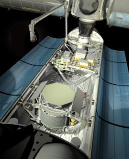
18 AMS-Detector Ready for flight STS-134 (19 April 211) 18


19 Tracker Thermal Control system (TTCS) TTCS: Bringing the 15 Watt from the insulated detector center to the external radiator panels. Keeping the detector temperature stable <3ºC over orbit. Evaporator set-point between -2ºC and +15ºC (Depending on seasonal temperature. 15 Watt Set point temperature Radiator temperature


20 MAGNETE Tracker Thermal Control system (TTCS) RADIATORE condensatori 144 WATT TRD TOF TRACKER TOF RICH ECAL 15 Watt detector with evaporator rings Cooling system component boxes (1 redundant) 2

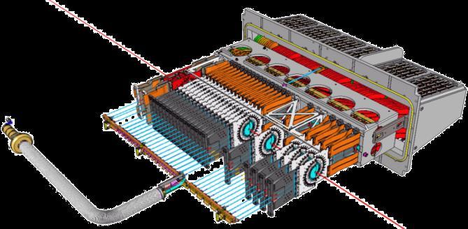
21 AMS-Tracker with CO 2 cooling rings. Tracker connections Inner plane thermal bars and hybrids Inner plane evaporator rings Inner plane silicon ladders 21


22 TTCS Evaporator system Top evaporator loops Inner plane thermal bars Outer plane thermal bars Bottom evaporator loops Tracker plane with evaporator loop Welding of the evaporators Thermal conductors 22

23 TTCS Schematics


24 TTCS Components Component box Evaporator section Condenser and radiators Heat exchanger Centrifugal pump Accumulator 24 24

25 TTCS Engineering Model Test Results The TTCS installed in AMS can only be tested in vacuum. All the functional tests have been done with an engineering model. Pre-heaters Cold orbit heater APS Accu Start-up radiator and with pumps DPS HX with pre-heaters Figure Error! No text of specified style in document.-1: TTCB Engineering Model lay-out Thermal stable operation with varying heat loads & varying orbital conditions

26 AMS Thermal Vacuum ESA-Estec in the LSS In April 21 the TTCS was tested in AMS in the Large Space Simulator (LSS) at ESA- Estec. TTCS radiators The LSS is a large vacuum chamber with nitrogen cooled walls to simulate the cold of space. The TTCS was tested under different wall temperatures. Orbital variations were simulated with IR heaters facing the radiator panels. IR lamps 26
27 Temperature( C) Temperature( C) Pump Speed (rpm) TTCS Test results from the LSS vacuum : Transient performance Evaporator( C) Silicon plane( C) Evaporator saturation( C) Pump liquid( C) Ram Radiator( C) W Evaporator saturation( C) Pump liquid( C) Ram Radiator( C) Wake Radiator( C) Primary pu ation( C) Pump 1 liquid( C) Ram Radiator( C) Wake Radiator( C) Primary pump speed (rpm) Secondary pump speed (rpm) Accumulator Single phase evaporator Pump speed Two- phase evaporator Redundant pump speed Detector Evaporator Wake Radiator Pumped liquid Ram Radiator : 21: : 3: 7-Apr-21 Time (hh:mm) 27


28 LHCb Detector 28


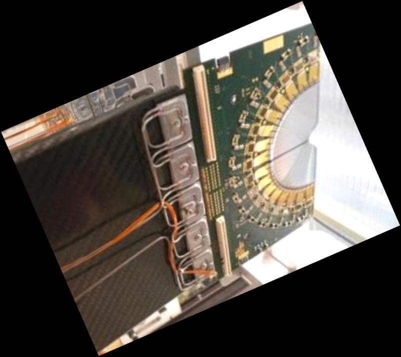

29 VTCS Evaporator 29


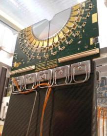

30 VTCS Evaporator 3
31 TLR_PM11 TL_VL19 TL_VL11 TR_VL11 TR_VL19 TL_AC11 TR_AC11 TL transfer line TR transfer line VTCS Schematics TL CO2 bridge VELO TR CO2 bridge TL_TT46 TL_VL2 TR_TT46 Liquid Pump TL_VL7 TR_VL7 TL_TT48 Velo vacuum tank with silicon modules, module base and CO 2 evaporator. TL_TT48 Electronic 3-way valve Electronic 2-way valve TL_PT12 Cooling plant at UXAC3 TR_PT12 Manual restriction valve PLC and electronics rack No return valve Electric heater TL_VL112 TR_VL112 Damper with heater TL_VL111 TL_HT14 TL_TT125 TL_HT15 TR_HT15 TR_TT125 TR_VL111 TR_HT14 Heat exchanger Pressure transmitter TL_PT14 TL_HT13 TL_HX12 Air-cooled SB chiller TR_HX12 TR_PT14 TR_HT13 Temperature transmitter TL_TT112 TL_HX11 TR_HX11 TR_TT112 TL_VL13 TL_PT11 Water-cooled SA chiller TLR_VL11 TR_VL13 TR_PT11 TL_TT112 TR_TT112 TL_TT122 TL_HT12 TL_PM11 TLR_TT112 TLR_TT122 TR_HX15 TR_PM11 TR_TT122 TR_HT12 TLR_HT12 TL CO2 system TLR system TLR_VL19 TR_VL18 TR CO2 system 31


32 Evaporator Passive tubing only VTCS Locations Transfer tube Concentric assembly Cooling Plant All active hardware LHCb experimental cavern 32


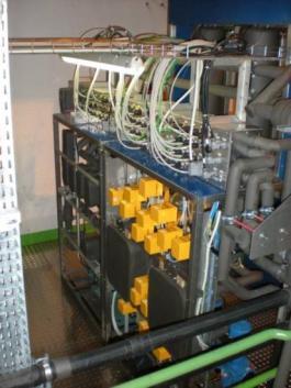
33 Accumulators VTCS Cooling plant Condensers Liquid pumps 33


")

34 VTCS Accumulator Cooling spiral for pressure decrease (Condensation) Thermo siphon heater for pressure increase (Evaporation) 34
35 Condenser Restriction Temperature( C), Level(%) Temperature( C), Level(%) Temperature( C), Level(%) Heatload (W) Start up of the VTCS during October 8 29 commissioning: 8:4 - Start-up with set-point -5 C 11:1 - Detector switched on 6 12:5 Set point to -15 C 15:3 - Set point to -25 C 5 17:1 - Set point to -3 C 18:2 - Set point to -35 C (System Limit) 19:1 - Set point to -34 C 4 19:3 - Set point to -25 C 2: - Detector Switched off Accumulator Set-point temperature Silicon temperature ( C) ( C) Pump liquid Accumulator temperature Set-point ( C) temperature Evaporator ( C) saturation Pump liquid temperature ( C) 7 3 VTCS Commissioning results: Start-up and operation ator Set-point temperature ( C) Pump liquid temperature ( C) Evaporator saturation temperature ( C) Accumulator liquid level (%) Detector heat load (W) Accu liquid level 1-Accumulator set-point Detector power A-Silicon temperature 9-Pumped liquid gas 1 Accumulator 2-6 9: 12: 15: 18: 21: 1-Oct-29 Time (hh:mm) Silicon temperature ( C) Accumulator Set-point temperature ( C) Pump liquid temperature ( C) Evaporator saturation temperature ( C) Accumulator liquid phase Cooling plant area Transfer lines (Ca. 1 5m) VELO area Evaporator / Modules C SP R57a chiller C SP gas 2-phase 9 Pump Concentric tube A C SP 35
 9-Pump inlet Liquid T=2 C Start-up")

36 Pressure (Bar) T=-4 C bverlaat@nikhef.nl VTCS Commissioning results: Start-up and operation in the PH-diagram SP=21 C (Start-up) 9-Pump inlet Liquid T=2 C Start-up sequence 1. Increase pressure to make liquid. SP=-5 C Freezing (Solid/Liquid) SP=-15 C T= C T=-2 C 2. Pump at high pressure and cool down in liquid mode 3. Lower pressure to desired set-point 4. Power-up detector SP=-25 C SP=-3 C SP=-35 C 2-Phase (Liquid/Vapor) T=-4 C Switch-off detector Lowest possible set-point (liquid approaches saturation line) Enthalpy (kj/kg) 36
37 Temperature( C) Temperature( C) Condenser Restriction gas 2-phase Accumulator 1 Accumulator Cooling plant area VTCS Commissioning results: Steady State Performance Transfer lines (Ca. 5m) VELO area Evaporator / Modules R57a chiller Return Fluid Evaporator 7 gas 2-phase 9 Pump 8 6 A Silicon 1 2 Concentric tube Evaporator outlet( C) 8. Condenser Inlet ( C) 9. Pump inlet liquid ( C) 7. Evaporator 1. Accumulator outlet( C) Saturation 8. Condenser ( C) Inlet ( C) 9. Pump inlet liquid ( C) 1 2 A. Module tip (Silicon)( C) 7. Evaporator outlet( C) 8. Condenser Inlet ( C) 9. Pump inlet liquid ( C) 1. Accumulator Saturation ( C) Detector Switched-off Detector Powered-Up Detector Switched-off 2 Detector Switched Off Detector Switched On C Liquid -3-4 Liquid Accumulator Set-Point ( C) Accumulator Set-Point ( C) 37
38 Temperature( C) Temperature( C) VTCS Commissioning results: Heat loads : Evaporator Heat Load (Detector On) 6-7: Evaporator Heat Load (Detector Off) 7-8: Transfer Tube Heat Pick-up (Detecto 6 6-7: 7-8: Transfer Tube Heat Pick-up (Detector On) 7-8: Transfer Tube Heat Pick-up(Detector Off) 7-8: Transfer Tube Internal Exchang tor Off) 7-8: Transfer Tube Internal Exchange (Detector On) 7-8: Transfer Tube Internal Exchange (Detector Off) ube Environemantal Heat (Detector On) 7-8: Transfer Tube Environemantal Heat (Detector Off) 7-8: Transfer Tube Internal Ex Detector Power 4 2 Environmental heat pickup in transfer line same order as detector power. (all heat pick-up only in the return line) Accumulator Set-Point ( C) 38-4
39 Temperature( C), Level(%) Temperature( C), Level(%) Temperature( C), Level(%) Heatload (W) Temperature( C) VTCS Commissioning results: Thermal Stability The 2PACL is a very high precision temperature control method. The Velo evaporator is controlled from 6m distance. The stability <.1 C; reaction time immediate (pressure control) (Note: Chiller is fluctuating ~8 C, Temperature archiving.1 C) TLPT3.Tsat TLPT12.Tsat TLTT16.temp TLTT17.temp TLHX12.watt : 1: 11: 12: 13: 1 1-Oct-29 Time (hh:mm) Silicon temperature ( C) Accumulator Set-point temperature ( C) Pump liquid temperature ( C) Evaporator saturation temperature ( C) Accumulator liquid level (%) Detector heat load (W) 8 temperature Silicon temperature ( C) ( C) Pump liquid Accumulator temperature Set-point ( C) temperature Evaporator ( C) saturation Pump liquid temperature ( C) Ev 8 A Accumulator Set-point Pumped liquid : 12: 15: 18: 21: 1-Oct-29 Time (hh:mm) Accu liquid level Detector power A-Silicon temperature Accumulator set-point
40 Temperature ( C), Power (Watt), Level (vol %) Temperature ('C), Liquid level (vol %), Power (%kw or Watt) bverlaat@nikhef.nl Accumulator response (powering up and down and a temperature change) Total C detector load (% kw) Evaporator Temperature ('C) Accumulator Liquid Level (vol %) Acumulator heating/cooling (% kw) Module VL11-C power (Watt) Module VL11-C cookie temperature ('C) Module VL11-C NTC temperature ('C) Module VL11-C NTC1 temperature ('C) Accu Heating/Cooling Detector half heat load (x1) Module Heat load Accu level -7 C -2-2 Silicon temperature Evaporator SP=-5 C SP=-25 C temperature -4 :3 1: 1:3 2: Clock time (Hour) Time (Hour) 4 4
41 Temperature( C), Stroke (mm) Temperature( C), Stroke (mm) Temperature( C), Stroke (mm) Temperature( C), Stroke (mm) Pressure Heatload (W) VTCS Commissioning results: Superheating An interesting phenomenon is observed, which needs attention for future systems. Sometimes the liquid is slightly sub cooled and boiling does not always start immediately => Superheating! troke (mm) Evaporator saturation 1 ( C) Evaporator 12 begin ( C) Evaporator 12 end ( C) Evaporator 27 begin ( C) Evaporator 27 end ( C) C D C ,1, E 9 1 9, C -8-2 HX12 heat Enthalpy 4 1 h [kj/kg] -4 3,5 B 8 1,13 C -2 C -4 C -2 C A C 2 C C HX12 inlet HX12 outlet HX27 heat Pump stroke HX27 in & outlet Evaporator temperature Pump stroke (mm) Evaporator saturation ( C) Evaporato Pump stroke (mm) Evaporator saturation ( C) Evaporator 1 12 begin ( C) Evaporator 12 end ( C) Evaporat Pump stroke (mm) Evaporator saturation ( C) Evaporator 1 12 begin ( C) Evaporator 12 end ( C) Evaporator 27 begin ( C) Evaporator 27 end ( C) Evapora Evaporator saturation ( C) Evaporator 12 begin ( C) Evaporator 12 end ( C) Evaporator 27 begin ( C) Evaporator 27 end ( C) Evaporator 12 heatload (watt) Evaporator 27 heatload (watt) 8 1 VTCS start-up and operating cycle s : 18:3 19: 19:3 2: 2:3 21: 2-Oct-29 Time (hh:mm)
42 Future CO 2 cooling projects CO 2 cooling is foreseen for the following experiments: Near future: Atlas Inner B-layer (IBL) detector: 213 (1.5kW@-4ºC) CMS-pixel detector: 214 (9kW@-2ºC) Belle-II pixel vertex detector: 214 (1.2 kw@-35ºc XFEL R&D: 211 (1.2kW@-15ºC) Atlas silicon detector upgrade Atlas silicon detector upgrade: 22 (18kW@-4ºC) CMS silicon detector upgrade: 22 (1kW@-25ºC) International Linear Collider TPC: 2xx (2kW@+2ºC) Any more CO 2 cooling projects that we are not aware off? Please tell me. 42


")


43 Near future CO 2 challenges CMS pixel detector (Extreme small diameter small dp allowed) Belle-II pixel detector (Rapid Prototyping heat sink) Atlas IBL detector (Long in and outlet tubing) 43
44 CO 2 research plants To support the research on CO 2 cooling plants are constructed all over the world. At CERN/Nikhef the following systems are operational: Nikhef 2PACL system CERN Cryolab 2PACL system Systems under development: CERN-DT / Nikhef 1kW system CERN-DT 1W system 44


45 Operational: Nikhef CO 2 2PACL test system Capacity 1kW Evaporative temperature range: -4ºC to +25ºC Universal test box for experiments Pre set-up temperature sensors and pressure sensors. Controllable power supply Automatic scanning connected experiments 45
, Inlet enthalpy (Inlet temperature) Mass flow Power Several structures have been tested and analyzed.")
46 PVSS Automated scanning Easy test procedure. Steady state data recorded after each setting change. Able to change: Outlet pressure (Evaporative Temperature), Inlet enthalpy (Inlet temperature) Mass flow Power Several structures have been tested and analyzed. Tests fully protected to overheating. Power Flow Dec 29 Carbon tube scanning results, data recorded at steady state 46


")
47 Operational: CERN-Cryolab 2PACL test system Capacity W to 3kW 27 liter accumulator for large volume experiments. Temperature range +25ºC to -45ºC (To be verified in upcoming commissioning) Small (15 watt) and large experiment outlet. 47
48 Accumulator Under development: CERN / Nikhef 1kW Unit Schematics. Common CERN-DT / Nikhef development. User friendly system, designed for series production to distribute among labs. Project can use additional collaborators. If you want to invest money and man power in CO 2 cooling, please consider joining this collaboration and benefit from the 12 years of CO 2 cooling knowledge. Base design for future cooling plants (IBL, XFEL) 7 6 fill PR18 PT18 TT18 8 CO2 from experiment vent Experiment connection CO2 to experiment FL112 VL111 evacuate VL18 VL16 VL15 PR16 by-pass HT11.temp ¼ ⅜ ⅜ VL112 VL11 ⅜ TT15 5 ⅜ ¼ HT14.temp HT14 PM111 PR11 PT11 AC11 HT11 ⅜ PT28 TT28 ½ 7 8 ⅜ 6 ½ VL29 VL26 hot gas 1 R44A condenser 2 R44A compressor cooling water Cooling water ¼ FT13 ¼ 4 ⅜ 9 HX24 5 VL13 FL13 VL14 3 ¼ PM12 PR14 PT14 TT14 2 PM11 Condenser TT11 1 ¼ ⅜ 4 VL24 Commercial chiller 3 CU Pump option


49 1.6 m bverlaat@nikhef.nl CO 2 Cooling unit mechanical design Electronics cabinet for experiments Valves Control cabinet with touch screen Accumulator Chiller connections Condenser Experiment and fill connections Liquid pumps 49
50 Conclusions CO 2 cooling is the future for particle physics cooling. CO 2 cooling seems also very beneficial for other scientific instrument cooling. 2PACL technology is interesting as a system principle (high stability, easy to operate). If you plan to invest money and manpower in CO 2 cooling, consider to join the CERN/NIKHEF 1kW unit development. 5
CO 2 COOLING FOR THE LHCB-VELO EXPERIMENT AT CERN.
 GL2008 8 th IIF/IIR Gustav Lorentzen Conference on Natural Working Fluids 7-10 September 2008 Copenhagen, Denmark Paper number: xxx CO 2 COOLING FOR THE LHCB-VELO EXPERIMENT AT CERN. B. Verlaat*, A. Van
Operational aspects of the VELO cooling system of LHCb
 Operational aspects of the VELO cooling system of LHCb Eddy Jans (Nikhef) on behalf of the LHCb VELO group Introduction Main components and operation principle of the system Issues: how to prevent and
PoS(Vertex 2007)009. CO 2 cooling experience (LHCb) Martin van Beuzekom, Ann Van Lysebetten 1, Bart Verlaat
009. CO 2 cooling experience (LHCb) Martin van Beuzekom, Ann Van Lysebetten 1, Bart Verlaat") CO 2 cooling experience (LHCb) Martin van Beuzekom,, Bart Verlaat Nikhef Kruislaan 409, 09 SJ Amsterdam, The Nerlands E-mail: Ann.Van.Lysebetten@cern.ch The rmal control system of LHCb Vertex LOcator (VELO)
CO 2 cooling experience (LHCb) Martin van Beuzekom,, Bart Verlaat Nikhef Kruislaan 409, 09 SJ Amsterdam, The Nerlands E-mail: Ann.Van.Lysebetten@cern.ch The rmal control system of LHCb Vertex LOcator (VELO)
DESIGN, MANUFACTURE AND TEST RESULTS OF THE VTCS CO 2 EVAPORATOR FOR THE LHCB EXPERIMENT AT CERN.
 HEFAT2010 7 th International Conference on Heat Transfer, Fluid Mechanics and Thermodynamics 19-21 July 2010 Antalya, Turkey DESIGN, MANUFACTURE AND TEST RESULTS OF THE VTCS CO 2 EVAPORATOR FOR THE LHCB
TRACI, A MULTIPURPOSE CO 2 COOLING SYSTEM FOR R&D
 Paper No: GL-208 RACI, A MULIPURPOSE CO 2 COOLING SYSEM FOR R&D B. Verlaat(a,b), L. Zwalinski(b), R. Dumps(b), M. Ostrega(b,c), P. Petagna(b) and. Szwarc(b,c) (a) National Institute for Subatomic Physics
Cooling test results C-side replacement detector
 Cooling test results C-side replacement detector Nikhef number: Item number: Date: 2/10/2011 Page: 1 of 36 39300-MT-00003 AA2232 Status: In Work Revision: A.5 Project: LHCb VELO Department: Mechanical
THE THERMOSIPHON COOLING SYSTEM OF THE ATLAS EXPERIMENT AT THE CERN LARGE HADRON COLLIDER
 THE THERMOSIPHON COOLING SYSTEM OF THE ATLAS EXPERIMENT AT THE CERN LARGE HADRON COLLIDER M. Battistin, S. Berry, A. Bitadze, P. Bonneau, J. Botelho-Direito, G. Boyd, F.Corbaz, O. Crespo-Lopez, E.Da Riva,
CO 2 cooling for HEP experiments
 CO cooling for HEP experiments B. Verlaat, M. Van Beuzekom, A. Van ysebetten Nikhef, Kruislaan 49, 198 SJ Amsterdam, The Netherlands bverlaat@nikhef.nl Abstract The new generation silicon detectors require
Safety Analysis of the 3 main parts in the CO2 system
 Safety Analysis of the 3 main parts in the CO2 system Nikhef number: Item number: Date: 11/11/2010 Page: 1 of 38 39300-MT-00001 AA1578 Status: In Work Revision: A.3 Project: Department: Mechanical Technology
Development of the CMS Phase-1 Pixel Online Monitoring System and the Evolution of Pixel Leakage Current
 Development of the CMS Phase-1 Pixel Online Monitoring System and the Evolution of Pixel Leakage Current Fengwangdong Zhang On behalf of CMS Pixel Collaboration The 9th International Workshop on Semiconductor
CO2 kick-off NIKHEF - Cooling activities organization at CERN
 CO2 kick-off meeting @ NIKHEF - Cooling activities organization at CERN CERN EN/CV/DC 1 The background (1/2) The LHC Detector Cooling systems have been mainly realized at CERN. They use water or perfluorocarbons
Due to its low temperature glide about 1.5 approx. (75% less than R-407C and R-427A), it is suitable for a wide range of applications.
, it is suitable for a wide range of applications.") TECHNICAL DATA SHEET R434A () Features and uses of R-434A () is a non-flammable HFC mixture. ODP = 0, compatible with traditional mineral lubricants, alkyl benzene and also with synthetic POE, so there
TECHNICAL DATA SHEET R434A () Features and uses of R-434A () is a non-flammable HFC mixture. ODP = 0, compatible with traditional mineral lubricants, alkyl benzene and also with synthetic POE, so there
CHAPTER 2 EXPERIMENTAL APPARATUS AND PROCEDURES
 CHAPTER 2 EXPERIMENTAL APPARATUS AND PROCEDURES The experimental system established in the present study to investigate the transient flow boiling heat transfer and associated bubble characteristics of
STATUS OF THE LHC EXPERIMENTS.
 STATUS OF THE LHC EXPERIMENTS. Mario Calvetti Chairman of the LHC Committee INFN and University of Florence calvetti@fi.infn.it Abstract A brief description of the status of the preparation of the large
FS 231: Final Exam (5-6-05) Part A (Closed Book): 60 points
 Part A (Closed Book): 60 points") Name: Start time: End time: FS 231: Final Exam (5-6-05) Part A (Closed Book): 60 points 1. What are the units of the following quantities? (10 points) a. Enthalpy of a refrigerant b. Dryness fraction of
Name: Start time: End time: FS 231: Final Exam (5-6-05) Part A (Closed Book): 60 points 1. What are the units of the following quantities? (10 points) a. Enthalpy of a refrigerant b. Dryness fraction of
Paper No. : 04 Paper Title : Unit Operations in Food processing Module 11 : Principles of Refrigeration
 Paper No. : 04 Paper Title : Unit Operations in Food processing Module 11 : Principles of Refrigeration 11.1 Introduction Preservation of foods is a vital processing step in food processing. There are
RIGID DC LIQUID CHILLER
 RIGID DC LIQUID CHILLER Phone: +86-579-8837-9768 Email:info@rigidhvac.com Website: www.rigidchill.com 1 1. WHAT S LIQUID CHILLER? Liquid Chiller cooling refers to cooling by means of the convection or
EN-CV: LHCb SciFi Common chiller. Martin Doubek September 25, 2017
 EN-CV: LHCb SciFi Common chiller Martin Doubek September 25, 2017 Common chiller Novec plant (pumps) 8 kw SciFi 9.4 kw ~ 30 kw UT + Velo CO 2 plant 7+4 kw Evaporation ~ -48 C Evaporation ~ -65 C 02.05.2017
Refrigerator/Heat pump
 UMEÅ UNIVERSITY 2013-12-16 Department of Physics Leif Hassmyr Updates versions Joakim Ekspong 2017-10-31 Refrigerator/Heat pump 1 Task 1. Understand the principle of a refrigerator/heat pump and know its
A CRYOGENIC TEST STATION FOR SUBCOOLING HELIUM HEAT EXCHANGERS FOR LHC
 EUROPEAN ORGANIZATION FOR NUCLEAR RESEARCH European Laboratory for Particle Physics Large Hadron Collider Project LHC Project Report 386 A CRYOGENIC TEST STATION FOR SUBCOOLING HELIUM HEAT EXCHANGERS FOR
STUDY ON THE CONTROL ALGORITHM OF THE HEAT PUMP SYSTEM FOR LOAD CHANGE
 Numbers of Abstract/Session (given by NOC) - 1 - STUDY ON THE CONTROL ALGORITHM OF THE HEAT PUMP SYSTEM FOR LOAD CHANGE Seok Ho Yoon, Kong Hoon Lee, Chan Ho Song, and Ook Joong Kim Environment and Energy
Heat-Engineering Trainer. (Refrigeration, Air Conditioning, Boiler, Geothermal)
") Heat-Engineering Trainer (Refrigeration, Air Conditioning, Boiler, Geothermal) Standard Refrigeration trainer (AV-RH-R-1000) 1. The possibility of the experiment on temperature, pressure, automatic control
Heat-Engineering Trainer (Refrigeration, Air Conditioning, Boiler, Geothermal) Standard Refrigeration trainer (AV-RH-R-1000) 1. The possibility of the experiment on temperature, pressure, automatic control
HIGH QUALITY VAPOR PHASE REFLOW SOLDERING. SMTA Arizona-Sonora December 4th 2012
 HIGH QUALITY VAPOR PHASE REFLOW SOLDERING THE ADVANCED SOFT SOLDERING TECHNOLOGY SMTA Arizona-Sonora December 4th 2012 IBL Reflow soldering is a complex physical and chemical process. The demand of lead
VTCS evaporator block design and prototyping. Status report July 2004
 VTCS evaporator block design and prototyping Bart Verlaat, Luc van Diepen & Martin Doets (NIKHEF) Frans Mul (VU) 30-Jul-04 bverlaat@nikhef.nl 1 VTCS evaporator block design (1) Detail of cooling block
LCTPC Setup at the DESY Testbeam. AWLC 14, Fermilab , R. Diener, DESY
 Setup at the DESY AWLC 14, Fermilab 14.05.2014, R. Diener, DESY Page 1 DESY II facility offers 3 beam lines with 1-6 GeV electrons Infrastructure DESY II / Area 24/1 telescopes Solenoid and Dipole magnet
Experimental investigation of Hybrid Nanofluid on wickless heat pipe heat exchanger thermal performance
 Experimental investigation of Hybrid Nanofluid on wickless heat pipe heat exchanger thermal performance #1 Jaydev S. Bade, #2 Dr. Nitin U. Korde 1 Department of Mechanical Engineering, Savitribai Phule
Homework Chapter2. Homework Chapter3
 Homework Chapter2 2/1 A storage tank holds methane at 120 K, with a quality of 25 %, and it warms up by 5 C per hour due to a failure in the refrigeration system. How long time will it take before the
RS-70 is suitable as a direct replacement for R-22 in low, medium and high temperatures in a great number of applications:
 TECHNICAL DATA SHEET Features and uses of is a non-azeotropic blend of HFC with zero Ozone Depletion Potential et low Global Warming Potential (GWP), formulated to meet the requirements of the F-Gas Regulation
Summary: thermal analysis, CFD simulations. - Enrico Da Riva - CERN (EN/CV/PJ) Workshop on SiPM cooling for Fiber Tracker, 17 October 2013
 Workshop on SiPM cooling for Fiber Tracker, 17 October 2013") Summary: thermal analysis, CFD simulations - Enrico Da Riva - CERN (EN/CV/PJ) Workshop on SiPM cooling for Fiber Tracker, 1 Contents A. Computational Fluid Dynamics (CFD) simulations for design optimization
Summary: thermal analysis, CFD simulations - Enrico Da Riva - CERN (EN/CV/PJ) Workshop on SiPM cooling for Fiber Tracker, 1 Contents A. Computational Fluid Dynamics (CFD) simulations for design optimization
Summary of Comments (Washington Revisions November 7, 2000) Update November 27, 2000
 Update November 27, 2000") SAE Alternate Refrigerant Cooperative Research Program Summary of Comments (Washington Revisions November 7, 2000) Update November 27, 2000 To: Alternate Refrigerant Task Force Members From: Ward Atkinson
SAE Alternate Refrigerant Cooperative Research Program Summary of Comments (Washington Revisions November 7, 2000) Update November 27, 2000 To: Alternate Refrigerant Task Force Members From: Ward Atkinson
Refrigeration Cycles MOHAMMAD FAISAL HAIDER. Bangladesh University of Engineering and Technology
 Refrigeration Cycles MOHAMMAD FAISAL HAIDER LECTURER Department of Mechanical Engineering Department of Mechanical Engineering Bangladesh University of Engineering and Technology Objectives Introduce the
Remote Helium Cooling Loops for Laboratory Applications
 Remote Helium Cooling Loops for Laboratory Applications T. Trollier, J. Tanchon, Y. Icart, A. Ravex Absolut System SAS Meylan 38240 FRANCE ABSTRACT In order to provide high cooling capacity to vibration
Isotemp. Improve the productivity of your laboratory with accurate, efficient temperature control products from Fisher Scientific.
 Isotemp Bath Circulators and Chillers Improve the productivity of your laboratory with accurate, efficient temperature control products from Fisher Scientific. Choose the temperature control option that
Expected needs in Electronics for the CERN Experiments. 5 October 2015
 Expected needs in Electronics for the CERN Experiments 5 October 2015 Philippe.Farthouat@cern.ch 2 The LHC Experiments 3 ATLAS Detector 4 CMS Detector 5 Collaborations Last generation of HEP detectors
1 /35 2 /35 3 /30 Total /100
 Test is open book and notes. Answer all questions and sign honor code statement: I have neither given nor received unauthorized assistance during this exam. Signed Remember to show your work partial credit
Hot Reservoir Stainless-Methanol Variable Conductance Heat Pipes for Constant Evaporator Temperature in Varying Ambient Conditions
 Joint 18th IHPC and 12th IHPS, Jeju, Korea, June 12-16, 2016 Hot Reservoir Stainless-Methanol Variable Conductance Heat Pipes for Constant Evaporator Temperature in Varying Ambient Conditions Jens Weyant
Enhancement of COP in Vapour Compression Refrigeration System
 Enhancement of COP in Vapour Compression Refrigeration System M. Krishna Prasanna #1 M.E student, Heat Transfer studies in Energy Systems Department of Mechanical Engg., Andhra University Visakhapatnam-530003,
Experimentation and Fabrication of Iceplant Using Ecofriendly Refrigerant
 Experimentation and Fabrication of Iceplant Using Ecofriendly Refrigerant Shubham Rangari 1, Shubham Mahakalkar 2, Shubham Tiple 3, Praharsh Marathe 4, Sameer Bansod 5, Sunnyraj Katam 6, Suraj Nagrare
ATLAS Pixel Upgrade for HL-LHC
 ATLAS Pixel Upgrade for HL-LHC Elisabeth Petit on behalf of the LPSC and LAPP teams Enigmass general meeting 9th of December 2016 1 The teams Physicists: P. Barroca, S. Jézéquel, R. Lafaye, J. Levêque,
Performance Enhancement of Refrigeration Cycle by Employing a Heat Exchanger
 Performance Enhancement of Refrigeration Cycle by Employing a Heat Exchanger Abstract Shoeb J. Inamdar 1 H.S. Farkade 2 M. Tech student. (Thermal Engineering) 1, Asst. Professor 2 Department of Mechanical
EFFECT OF PAG OIL CIRCULATION RATE ON THE HEAT TRANSFER PERFORMANCE OF AIR-COOLED HEAT EXCHANGER IN CARBON DIOXIDE HEAT PUMP SYSTEM
 - 1 - EFFECT OF PAG OIL CIRCULATION RATE ON THE HEAT TRANSFER PERFORMANCE OF AIR-COOLED HEAT EXCHANGER IN CARBON DIOXIDE HEAT PUMP SYSTEM Shun YOSHIOKA, Hyunyoung KIM, Kazushige KASAI, Daikin Industries,
HVAC Fundamentals & Refrigeration Cycle
 HVAC Fundamentals & Refrigeration Cycle Change of State of Water & the Refrigeration Cycle Change of State Water The Basic Refrigeration Cycle Types of DX Systems The Chilled water System The Cooling Tower
TEST REPORT #14. System Drop-In Test of Refrigerant Blend ARM-42a in an Air-Cooled Screw Chiller
 Air-Conditioning, Heating, and Refrigeration Institute (AHRI) Low-GWP Alternative Refrigerants Evaluation Program (Low-GWP AREP) TEST REPORT #14 System Drop-In Test of Refrigerant Blend ARM-42a in an Air-Cooled
R10. IV B.Tech I Semester Regular/Supplementary Examinations, Nov/Dec REFRIGERATION & AIR-CONDITIONING (Mechanical Engineering)
") Set No. 1 IV B.Tech I Semester Regular/Supplementary Examinations, Nov/Dec - 2014 REFRIGERATION & AIR-CONDITIONING (Mechanical Engineering) Time: 3 hours Max. Marks: 75 Answer any FIVE Questions All Questions
Set No. 1 IV B.Tech I Semester Regular/Supplementary Examinations, Nov/Dec - 2014 REFRIGERATION & AIR-CONDITIONING (Mechanical Engineering) Time: 3 hours Max. Marks: 75 Answer any FIVE Questions All Questions
STUDY ON HYBRID SYSTEM OF SOLAR POWERED WATER HEATER AND ADSORPTION ICE MAKER
 , Volume 6, Number 4, p.168-172, 2005 STUDY ON HYBRID SYSTEM OF SOLAR POWERED WATER HEATER AND ADSORPTION ICE MAKER Zhaohui Qi School of Energy Science and Engineering, Centralsouth University, Changsha,
Heat pump and energy recovery systems
 SBS5311 HVACR II http://ibse.hk/sbs5311/ Heat pump and energy recovery systems Ir. Dr. Sam C. M. Hui Faculty of Science and Technology E-mail: cmhui@vtc.edu.hk Oct 2017 Contents Basic concepts Air-to-air
EXPERIMENTAL INVESTIGATION OF WATER COOLER SYSTEM BY USING ECO-FRIENDLY REFRIGERANT (R-134a)
") EXPERIMENTAL INVESTIGATION OF WATER COOLER SYSTEM BY USING ECO-FRIENDLY REFRIGERANT (R-134a) Abstract- With the recent government regulations, of banning the ozone depleting substances and Kyoto protocol
EXPERIMENTAL INVESTIGATION OF WATER COOLER SYSTEM BY USING ECO-FRIENDLY REFRIGERANT (R-134a) Abstract- With the recent government regulations, of banning the ozone depleting substances and Kyoto protocol
PREDICTION OF THE PRESSURE DROP OF CO 2 IN AN EVAPORATOR USED FOR AIR COOLING ABSTRACT 1. INTRODUCTION 2. EXPERIMENTAL SET-UP AND PROCEDURE
 PREDICTION OF THE PRESSURE DROP OF CO 2 IN AN EVAPORATOR USED FOR AIR COOLING M. POIRIER, D. GIGUÈRE, Z. AIDOUN, M. OUZZANE Natural Resources Canada, CANMET Energy Technology Centre-Varennes 1615, Lionel
Advantages / Characteristics
 Air to Air 50 W 30 W cooling capacity 163x104x144mm (LxBxH) 1,9 kg Air to Air 70 W 36 W cooling capacity 163x104x144mm (LxBxH) 1,9 kg Air to Air 75 W 30 W cooling capacity 130x109x163mm (LxBxH) 1,5 kg
Waste Heat Utilization of Vapor Compression Cycle for Operation of Vapor Absorption System
 Waste Heat Utilization of Vapor Compression Cycle for Operation of Vapor Absorption System 1 Avnish Chandra Pandey, 2 M. Akash Rao, 3 Sabyasachi Sahoo, 4 Narendra Kumar Students, Department of Mechanical
Towards a Detector Control System for the ATLAS Pixeldetector
 Towards a Detector Control System for the ATLAS Pixeldetector Pixel2002, Carmel September 2002 Overview of the Detector Control System The Front End System The Back End System Experience with the Testbeam
A Comparison Between Refrigerants Used In Air Conditioning
 A Comparison Between Refrigerants Used In Air Conditioning Derya Özkan, Özden Agra and Özlem Çetin University of Yildiz Technical University, Turkey Corresponding email: tumer@yildiz.edu.tr SUMMARY It
Air is our element. energy recovery our passion. Rotors overview. Quick guide GOST VDI 6022
 Rotors overview Quick guide GOST VDI 622 Rotors overview Rotor type Heat recovery Preferred application Wave heigh Thickness of material Condensations Rotor P/PT [ C] 1% Summer Winter 7 1 1-1 - [g/kg]
Development of Energy Efficient R-134a Automotive Air Conditioning System Using Internal Heat Exchanger
 , July 6-8, 2011, London, U.K. Development of Energy Efficient R-134a Automotive Air Conditioning System Using Internal Heat Exchanger Avinash. D. Desai, S. N. Sapali, Parthasarathi. V. Garikipati Abstract:
"COP Enhancement Of Domestic Refrigerator By Sub cooling And Superheating Using Shell &Tube Type Heat Exchanger"
 "COP Enhancement Of Domestic Refrigerator By Sub cooling And Superheating Using Shell &Tube Type Heat Exchanger" 1 Prof.Gaffar G.Momin, 2 Sagar B. Tupe, 2 Swapnil A. Parate 2 Omkar G. Yewale 2 Aakash P.
Compendium DES July 2016, CARN
 Compendium DES July 2016, CARN 1 Contents Contents... 2 1. Energy balance... 4 Using Energy Balance for analyzing energy systems... 4 Energy Balance definition... 4 Steady state, steady flow... 4 Methodology...
Oyelami S., Bolaji B. O.
 International Journal of Scientific & Engineering Research, Volume 6, Issue 6, June-2015 1158 Experimental Investigation of the Performance of Liquefied Petroleum Gas (LPG) Refrigerant in A Vapour Compression
Laird Thermal Systems Application Note. Bi-directional Microcontrollers Monitor and Protect Medical Equipment
 Laird Thermal Systems Application Note Bi-directional Microcontrollers Monitor and Protect Medical Equipment Contents Overview...3 Thermal Management Technologies...3 Design Example...3 Thermoelectric
Performance Evaluation of VCRS with Nested Helical Shaped Condenser by Using R134a as Refrigerant
 Performance Evaluation of VCRS with Nested Helical Shaped Condenser by Using R134a as Refrigerant Bukke Bhagyalathamma 1, Dr.Smt.G.Prasanthi 2 Department 1,2,Department of Mechanical Engineering,PG Scholor
Energy Saving & Eco-Friendly Refrigerant
 Technical Seminar Energy Saving & Eco-Friendly Refrigerant Presented By Eva Yim Business Development Director Stephen Cheung Engineering Director Date : Oct 16, 2012 Others 25% Lighting 15% Air Conditioning
2008 JINST 3 S The CMS experiment at the CERN LHC THE CERN LARGE HADRON COLLIDER: ACCELERATOR AND EXPERIMENTS.
 PUBLISHED BY INSTITUTE OF PHYSICS PUBLISHING AND SISSA RECEIVED: January 9, 2008 ACCEPTED: May 18, 2008 PUBLISHED: August 14, 2008 THE CERN LARGE HADRON COLLIDER: ACCELERATOR AND EXPERIMENTS The CMS experiment
Refrigeration System with a Capillary Tube and a Thermostat
 Exercise 2-1 Refrigeration System with a Capillary Tube Part A: REFRIGERATION CIRCUIT OBJECTIVE When you have completed this part, a refrigeration circuit using a capillary tube as a metering device will
Air Liquide Advanced Technologies Division Sassenage, 38360, France
 Published in AIP Conference Proceedings 1218, pp. 1476-1483 (2010) OPERATION RESULTS OF THE KSTAR HELIUM REFRIGERATION SYSTEM H.- S. Chang1, E. Fauve2, D.-S. Park1, J.-J. Joo1, K.-M. Moon1, K.-W. Cho1,
AVAILABILITY AND RELIABILITY OF CERN CRYOPLANTS
 AVAILABILITY AND RELIABILITY OF CERN CRYOPLANTS on behalf of the Cryogenics for Accelerator Group Accelerator Technology Department CERN, Geneva, Switzerland Outline Introduction Cryogenic systems layout
EVALUATION OF REFRIGERANT R290 AS A REPLACEMENT TO R22
 EVALUATION OF REFRIGERANT R290 AS A REPLACEMENT TO R22 Ameya P. Shrivastava 1, Choudhari Chandrakishor S. 2 1,2 Mechanical Department, AISSMS College of Engineering, Pune 411001, (India) ABSTRACT HCFC
Math. The latent heat of fusion for water is 144 BTU s Per Lb. The latent heat of vaporization for water is 970 Btu s per Lb.
 HVAC Math The latent heat of fusion for water is 144 BTU s Per Lb. The latent heat of vaporization for water is 970 Btu s per Lb. Math F. to C. Conversion = (f-32)*(5/9) C. to F. Conversion = C * 9/5 +
Thermodynamics I. Refrigeration and Heat Pump Cycles
 Thermodynamics I Refrigeration and Heat Pump Cycles Dr.-Eng. Zayed Al-Hamamre 1 Content Introduction The Reversed Carnot Cycle The Ideal Compression Refrigeration Systems Deviation from the ICRS Selection
Pressure Enthalpy Charts
 Pressure Enthalpy Charts What is a p-h Diagram? A p-h diagram is a diagram with a vertical axis of absolute pressure and a horizontal axis of specific enthalpy. "Enthalpy is the amount of energy in a substance
Thermal Performance of a Loop Thermosyphon
 Tamkang Journal of Science and Engineering, Vol. 13, No. 3, pp. 281 288 (2010) 281 Thermal Performance of a Loop Thermosyphon Shung-Wen Kang*, Meng-Chang Tsai, Chih-Sheng Hsieh and Jian-You Chen Department
R718 TURBO CHILLERS AND VACUUM ICE GENERATION TWO APPLICATIONS OF A NEW GENERATION OF HIGH SPEED, HIGH CAPACITY R718 CENTRIFUGAL COMPRESSORS
 TURBO CHILLERS AND VACUUM ICE GENERATION TWO APPLICATIONS OF A NEW GENERATION OF HIGH SPEED, HIGH CAPACITY CENTRIFUGAL COMPRESSORS Marcus HONKE, Mathias SAFARIK, Ralf HERZOG Institute of Air Handling and
Purpose of Refrigeration
 Refrigeration Outline Purpose of refrigeration Examples and applications Choice of coolant and refrigerants Phase diagram of water and CO 2 Vapor compression refrigeration system Pressure-enthalpy diagram
IJESRT. Scientific Journal Impact Factor: (ISRA), Impact Factor: 1.852
, Impact Factor: 1.852") IJESRT INTERNATIONAL JOURNAL OF ENGINEERING SCIENCES & RESEARCH TECHNOLOGY Experimental Study on Performance of Condenser of Two Different Types Used in Window Air Conditioner Madhu Jhariya *1, P.K. Jhinge
IJESRT INTERNATIONAL JOURNAL OF ENGINEERING SCIENCES & RESEARCH TECHNOLOGY Experimental Study on Performance of Condenser of Two Different Types Used in Window Air Conditioner Madhu Jhariya *1, P.K. Jhinge
Short Questions with Answers APPLIED THERMODYNAMICS(5 TH MECHANICAL) Chapter No-1
 Chapter No-1") Short Questions with Answers APPLIED THERMODYNAMICS(5 TH MECHANICAL) Chapter No-1 1. Define mechanical efficiency in case of an IC engine? [2015w] Ans. Mechanical efficiency of an I.C. engine is defined
Short Questions with Answers APPLIED THERMODYNAMICS(5 TH MECHANICAL) Chapter No-1 1. Define mechanical efficiency in case of an IC engine? [2015w] Ans. Mechanical efficiency of an I.C. engine is defined
Thomas J Kelly. Fundamentals of Refrigeration. Sr. Engineering Instructor Carrier Corporation. August 20, Page number: 1.
 Thomas J Kelly Sr. Engineering Instructor Carrier Corporation August 20, 2003 1 SESSION OBJECTIVES At the conclusion of this session you should be able to: 1. Describe the basics principles of refrigeration
Effect of Height Difference on The Performance of Two-phase Thermosyphon Loop Used in Airconditioning
 Purdue University Purdue e-pubs International Refrigeration and Air Conditioning Conference School of Mechanical Engineering 2014 Effect of Height Difference on The Performance of Two-phase Thermosyphon
U.G. Student, Department of Mechanical Engineering, J D Engineering College, Nagpur, Maharashtra, India
 DESIGN OF HYBRID AIR COOLER USING VAPOUR COMPRESSION REFRIGERATION SYSTEM Vimalkirti Shende 1, Sushil Borkar 2, Touseef Iqbal Qureshi 3 Asst. Prof. Nikhil Bhende 1 1,2,3 U.G. Student, Department of Mechanical
Public Services Building 155 N First Avenue Hillsboro, OR March 2012
 Public Services Building 155 N First Avenue Hillsboro, OR 97124 March 2012 Tests and report done by: Joel Klobas Emerging Energy Solutions Technical Director joelk@eeswest.com Contents Introduction...
Sarthak Thakar, 2 R.P.Prajapati 1
 PERFORMANCE ANALYSIS OF A DOMESTIC REFRIGERATOR USING VARIOUS ALTERNATIVEREFFRIGERANT 1 Sarthak Thakar, 2 R.P.Prajapati 1 PG Student, 2 Assitant Professor 1,2 Thermal Engineering Department, Sal Institute
 Design Based Comparative Study of Several Condensers Komal B. Dabhi 1, Prof. S. B. Thakore 2 1 Chemical Engg. Dept., L. D. College of Engineering, Ahmedabad 380015 2 Chemical Engg. Dept., L. D. College
REFRIGERATION CYCLE Principles of Mechanical Refrigeration Level 2: Cycle Analysis
 REFRIGERATION CYCLE Principles of Mechanical Refrigeration Level 2: Cycle Analysis Technical Development Program Technical Development Programs (TDP) are modules of technical training on HVAC theory, system
Calhoon MEBA Engineering School. Study Guide for Proficiency Testing Refrigeration
 Calhoon MEBA Engineering School Study Guide for Proficiency Testing Refrigeration 1. To prevent an injury when working with refrigerants, what safety precautions are necessary? 2. When halogens are in
Last exam / sista tent
 Värme- och strömningsteknik Thermal and flow engineering Refrigeration Kylteknik Ron Zevenhoven Exam 24-2-2017 4 questions, max. points = 8 + 8 + 6 + 8 = 30 All support material is allowed except for telecommunication
CHAPTER 1 INTRODUCTION
 1 CHAPTER 1 INTRODUCTION 1.1 Background The science which deals with creating a controlled climate in indoor space is called air conditioning. Earlier days the air-conditioning was treated as a luxury,
REFRIGERATION TUTOR. OBJECTIVE: To perform test on the refrigeration tutor to determine different COPs and other performance parameters.
 REFRIGERATION TUTOR OBJECTIVE: To perform test on the refrigeration tutor to determine different COPs and other performance parameters. EXPERIMENTAL SETUP: All the components of refrigeration bench are
Humidity sensors. Behavior in different environments. Supervisor: Vaclav Vacek Collaborators: Martin Doubek, Martin Janda and Michal Vitek 28.9.
 Humidity sensors Behavior in different environments Supervisor: Vaclav Vacek Collaborators: Martin Doubek, Martin Janda and Michal Vitek 28.9.29 CZECH TECHNICAL UNIVERSITY IN PRAGUE CERN Content Content...
BOOK 1 OVERVIEW RD2XRT INSTALLATION AND OPERATION MANUAL. Table of Contents ABOUT BOOK 1:
 4510 Helgesen Drive, Madison, WI, 53718 608.221.4499, 800.627.4499, Fax: 608.221.2824 support@renewaire.com www.renewaire.com RD2XRT INSTALLATION AND OPERATION MANUAL BOOK 1 OVERVIEW ABOUT BOOK 1: This
Drop-in Testing of Next-Generation R134a Alternates in a Commercial Bottle Cooler/Freezer
 Purdue University Purdue e-pubs International Refrigeration and Air Conditioning Conference School of Mechanical Engineering 2012 Drop-in Testing of Next-Generation R134a Alternates in a Commercial Bottle
PERFORMANCE OF DEEP FREEZER BY USING HYDROCARBON BLENDS AS REFRIGERANTS
 Int. J. Chem. Sci.: 14(S2), 2016, 665-674 ISSN 0972-768X www.sadgurupublications.com PERFORMANCE OF DEEP FREEZER BY USING HYDROCARBON BLENDS AS REFRIGERANTS J. THAVAMANI *, MARRIPUDAGALA KOMALI, SHAIK
Rotors overview. Quick guide GOST VDI 6022
 Rotors overview Quick guide GOST VDI 622 Rotors overview Rotor type Heat recovery Preferred application Wave heigh Thickness of material Condensations Rotor P/PT [ C] % Summer Winter - - [g/kg] 5 15 only
Water Cooled Condenser Using Nano Fluids
 Water Cooled Condenser Using Nano Fluids Vishal Vilas Khade Research Scholar, Department of Mechanical Engineering, Ashokrao Mane Group of Institutions, Vathar tarf Vadgaon, Kolhapur, India. Rahul A. Patil
we will examine only the vapour compression systems transfers to the Carnot cycle can serve as the initial model of the ideal refrigeration cycle.
 Refrigeration Cycle Reading Problems 10-1 10-5, 10-7, 10-9 10-11, 10-14, 10-39 Definitions a refrigeration system removes thermal energy from a low-temperature region and transfers heat to a high-temperature
Experimental Research On Gas Injection High Temperature Heat Pump With An Economizer
 Purdue University Purdue e-pubs International Refrigeration and Air Conditioning Conference School of Mechanical Engineering 2014 Experimental Research On Gas Injection High Temperature Heat Pump With
Design, Manufacturing of Chilled Water System for Process Cooling Application
 IJSTE - International Journal of Science Technology & Engineering Volume 2 Issue 11 May 2016 ISSN (online): 2349-784X Design, Manufacturing of Chilled Water System for Process Cooling Application Prof.
Ultra Deep Freezers -86 C. Biomedical Refrigeration I UF. Technology for life _8pages_dometic_UF.indd 1 10/09/08 11:17:32
 Ultra Deep Freezers Biomedical Refrigeration I UF -86 C Technology for life 504170_8pages_dometic_UF.indd 1 10/09/08 11:17:32 UF - Ultra Deep Freezers up to -86 C The models UF 455 G & UF 755 G reflect
Chapter 10. Refrigeration and Heat Pump Systems
 Chapter 10 Refrigeration and Heat Pump Systems Learning Outcomes Demonstrate understanding of basic vaporcompression refrigeration and heat pump systems. Develop and analyze thermodynamic models of vapor-compression
Thermodynamics II Chapter 5 Refrigeration
 Thermodynamics II Chapter 5 Refrigeration Mohsin Mohd Sies Fakulti Kejuruteraan Mekanikal, Universiti Teknologi Malaysia Objectives Introduce the concepts of refrigerators and heat pumps and the measure
Energy efficient vacuum freezing ice slurry generation using a R718 compressor
 Institute of Air-handling and Refrigeration (ILK Dresden) Energy efficient vacuum freezing ice slurry generation using a R718 compressor ATMOsphere Europe 2013 ILK Dresden R&D company Founded in 1964 Re-established
AIR CONDITIONING. Carrier Corporation 2002 Cat. No
 AIR CONDITIONING Carrier Corporation 2002 Cat. No. 020-016 1. This refresher course covers topics contained in the AIR CONDITIONING specialty section of the North American Technician Excellence (NATE)
NEW GENERATION INTELLIGENT CHILLER BOOSTER, ADIABATIC PRE-COOLING SYSTEM
 NEW GENERATION INTELLIGENT CHILLER BOOSTER, ADIABATIC PRE-COOLING SYSTEM H Y BRID COOLING Reduce chiller energy consumption by up to 37 % Increase chiller cooling capacity by up to 41% Achieve 100% protection
To accomplish this, the refrigerant fi tis pumped throughh aclosed looped pipe system.
 Basics Refrigeration is the removal of heat from a material or space, so that it s temperature is lower than that of it s surroundings. When refrigerant absorbs the unwanted heat, this raises the refrigerant