Refrigerator/Heat pump
|
|
|
- Dorcas Bradford
- 6 years ago
- Views:
Transcription
1 UMEÅ UNIVERSITY Department of Physics Leif Hassmyr Updates versions Joakim Ekspong Refrigerator/Heat pump
2 1 Task 1. Understand the principle of a refrigerator/heat pump and know its main components. 2. Determine the condenser, evaporator and compressor power. 3. Determine the coefficient of performance (c.o.p.) for: c.o.p. for cooling of cooling medium c.o.p. for heating of cooling medium real c.o.p. for the refrigerator real c.o.p. for the heat pump c.o.p. for a Carnot refrigerator c.o.p. for a Carnot heat pump v, real k, coolmedium v. coolmedium k, real k, Carnot v, Carnot Literature Course literature 1. Introduction 1.1 The principle of cold generation In order to clarify the principle of cold generation a well-known phenomena should be reminded. If you take some drops of a liquid that boils easy (for example ether or alcohol) in the hand it feels cold. The sensation will last until nothing of the liquid is left. The explanation is that all vaporization consumes heat. This heat of vaporization has to be brought to the liquid from the surrounding. In this case it is the hand that will lose heat. The above phenomenon also takes place in a refrigerator/heat pump. A working medium (cooling medium) with such properties that it condenses at the higher temperature and higher pressure, and vaporizes at the lower temperature and lower pressure is frequently used at many cooling processes. The heat absorption (cooling) occurs by that the cooling medium at low temperatures absorbs its heat of vaporization from the surrounding. The temperature at this point, the vaporization temperature, keeps constant. The reverse process is occurring when heat is emitted from the cooling medium during the condensation at higher temperature. This temperature is also constant during condensation and is called the condensation temperature.
3 2 1.2 Compression refrigerator / heat pump construction A simple refrigerator/heat pump system is composed of an evaporator, a compressor, a condenser and an expansion valve, and refrigerant piping and the drive motor for the compressor. In general, external power has to be added to drive the compressor motor and heat is either released from the cooling medium at the condenser to heat e.g. water, or adsorbed by the cooling medium at the evaporator to cool e.g. water. In fig.1, compression heat pump/refrigerator system is schematically plotted. Additional information about heat pumps can be found in appendix A. Fig.1 A schematic of a compressor driven heat pump/refrigerator system
4 3 2. Experimental setup 2.1 Description of our refrigerator/heat pump construction In fig.2, it is shown how the device used in this experiment is built. Fig.2 An overview schematic of the device that is used in this experiment. A. Compressor B. Condenser C. Expansion valve D. Evaporator E. Cooling medium container F. Flow meter G. Dryer H. Viewing glass I. Circulation pump J. Electric heater (2*1kW) P1-P6 Pressure gauges connected to the points 1-6 in the system. T1-T6 Pt-100 sensors for measuring the temperatures in the points 1-6 in the system. T7-T10 Pt-100 sensors for measuring the incoming and outgoing temperature in the water at the condenser and evaporator.

/0.385) C Fig.3 An image of the pressure gauges and the flow meter. Fig.4 An overview image of the device.")
5 4 Pressure and temperature sensors At the refrigerator/heat pump there is a board with 3 pressure gauges for the low-pressure side as well as for the highpressure side and a flow meter for determination of the cooling medium flow. There are also10 Pt-100 sensors in the system, connected to a box with an alteration switch, by which one gradually can make a four-wire resistance measurement of the Pt-100 sensors using the multimeter HP3478A. The temperature can now be determined from the relation: T=((R-100)/0.385) C Fig.3 An image of the pressure gauges and the flow meter. Fig.4 An overview image of the device. The water tank with heater is shown in the upper left and the pressure gauges is shown in the upper right next to the alternation box for measuring the temperature. In the bottom part the evaporator is shown to the left and the condenser, the expansion valve as well as the compressor to the right. The switch for turning on the compressor is on the outside of the shielding grid. The bottom plate On the bottom plate there are a total hermetic electric compressor and a water-cooled coaxial condenser. The cooling water coil of the condenser is equipped with a pressure controlled water valve, by which the working temperature of the condenser can be controlled. On the high pressure side after the condenser there are dryers, viewing glass and a cooling medium container for the excess of cooling medium. On the bottom plate there is, in a green isolated tank, a coaxial evaporator, which cools the water that is pumped from the green isolated tank on the upper plate by a circulation pump. The upper tank is equipped with an electrical heater (2*1 kw) for desired heat load on the cooling circuit. The system is also equipped with a twinpressure control for continuous running at desired runningpressures/temperatures.
6 5 2.2 Detailed information about individual parts in the device The main parts of the construction are a total hermetic electric compressor, a water-cooled coaxial condenser, an expansion valve, a coaxial evaporator and a separate water tank with heater. On the high pressure side after the condenser there are a cooling medium container, dryer, viewing glass and a flow meter to measure the flow of the cooling medium Compressor Total hermetic compressor model CAJ4492A for Forane R134a. The compressor is connected to a twin-pressure control. Its high-pressure side should stop the compressor at a maximum pressure of 15 bar overpressure. (Setting: 14 bar overpressure.). Its low-pressure side should stop the compressor at a minimum pressure of 0 bar overpressure, in order to avoid the compressor to suck air into the system. Switch on can e.g. occur at switch off-pressure plus 1 bar. (Setting: Switch off=2 bar overpressure. (in order to avoid the temperature in the water-cooling system of the vaporizer to be less than 0 C) and difference-switch on=switch off + 1 bar) Condenser COAX-2050H water-cooled coaxial condenser. A water valve on the cooling water pipe controls the cooling of the condenser. By setting this, the temperature of the cooling water of the condenser can be adjusted and the construction can be used as a heat pump. The setting for Forane R134a corresponds to a water temperature of about 40 C Expansion valve To the character of the thermostatic expansion valve is that it maintains a constant overheating in the evaporator even when the vaporization pressure is varying. (Usually 5 C) overheating. The thermostatic expansion valve works as follows: The sensor (2) is attached after the vaporizer (1) and thus senses the temperature of the outgoing low-pressure pipe (3). The sensor, which is filled with some medium that boils easy, is through the capillary tube (4) connected to the expansion valve and a pressure P 1, which magnitude is determined by the sensor-temperature, thus acts on the upper side of the membrane (5). The vaporization pressure P 2 (first part of the evaporator) and the spring pressure P 3 acts on the lower side of the membrane. At equilibrium: P 1 =P 2 +P 3 Fig. 5 A schematic of the expansion valve used in the device.

7 Evaporator WKV1 water-cooled coaxial evaporator. Cooling medium volume 0.5 dm 3 and cooling water volume.4 dm Water tank The heat absorbed from the water in the coaxial evaporator at the vaporization of the cooling medium is replaced by that water from an isolated water tank, equipped with a 2*1 kw heater, which is circulated through the coaxial evaporator using a circulation pump. Supplied electric heat is measured by a clip-on ammeter/voltmeter. The water volume of the tank = 30 liter Dryer Next after the condenser is a dryer containing silica gel and molecular sieve. Its purpose is to absorb existing water from the cooling medium and to collect pollution particles Viewing glass After the drying filter is a viewing glass through which one can observe the cooling medium while the system is running. During normal running conditions one should have a uniform flow of the fluid with no bubbles. If bubbles are observed it can be due to for example lack of cooling medium, a cut down in the fluid pipe or a fall of pressure of abnormal size Flow meter For measuring of the flow of cooling medium a flow meter Brooks instrument model BR is installed. Fig.6 The flow meter for the cooling medium. Reading of the flow value is done at the upper edge of the floating body. 100% turn of the scale corresponds to a cooling medium flow = 128 kg/h.
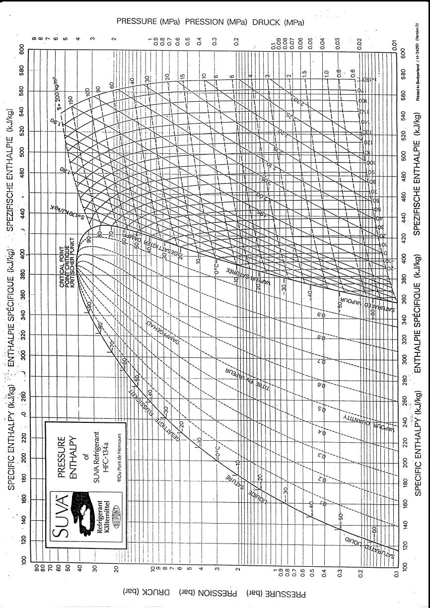
8 7 2.3 Typical failures, technical problems Normally a refrigerator-and heat pump construction would work without any operation-technical problem. Next some examples of problems that can occur are given. Moisture in the system can occur if air leaks into the system. Moisture can lead to that the expansion valve freezes during operation and prevents the cooling medium (Forane R134a) from circulating normally. Usually the moisture is removed by changing the dryer. The most common problem with refrigerators is that leakage occurs. This can be detected by leak-searching equipment. An example of such equipment is Ion-pump detector CPS model L-780. It detects a cooling medium leakage by sucking in gas from the leaking area between two high-voltage electrodes, which ionizes the cooling medium gas, and electrical charge carriers are created. The instrument can detect the current that now occurs. In handling with cooling mediums of all types caution should be exercised when these appear in the form of liquid. If cooling medium liquid leaks out it will at its vaporization immediately adopt a temperature corresponding to the pressure of the atmosphere. In the cooling medium diagram for Forane R134a a temperature of -25 C is read. If drops of cooling medium hit the eyes, frostbite immediately occurs. If there is risk of cooling medium to jet out protective goggles should be used. 2.4 Cooling medium diagram-pressure/enthalpy diagram Liquid Critical point Liquid+Vapor Vapor A common diagram to use for refrigerators/heat pumps is the log(p) vs. h diagram. The abscissa = enthalpy (h). The ordinate = log pressure (p). From this diagram one can read off the pressure and change in enthalpy between different states of the cooling medium. Besides pressure-and enthalpy values one can also, from the diagram, read off temperature-, specific volume and entropy values of the cooling medium. Temp. lines Entropy lines Spec. vol. lines The x-marked lines in the diagram indicate how much of the cooling medium that is vapour. Ex. x=0.6 60%vapour, 40% liquid X-lines
9 8 log P bar T c h A h B h kj/kg The compressor The compressor is sucking in dry saturated Forane R134a-vapour with temperature T c, heat content h A and specific volume V A. The point A represents the low-pressure vapor that is sucked in. If now the compression of the vapor in the compressor could be reversible and adiabatic, ds=0, it would be represented by the line A-B. The point B with temperature T B and enthalpy h B represents the state of the cooling medium just before the condenser. log P bar P h T c T h The condenser The compression is followed by the condensation, which occurs at constant pressure P h. The line B-C thus represents the condensation. The point C with temperature T h and enthalpy h C is thus the state of the cooling medium just before the expansion valve. h C h A h B h kj/kg log P bar P h P c T h T c h C h A h B kj/kg h The expansion valve In the expansion valve the pressure of the cooling medium is decreased from P h to P c. This pressure decrease takes place without a change in enthalpy, in other words the line C- D represents the process. The point D with temperature T c and enthalpy h C thus represents the state of the cooling medium just before the vaporizer..
10 9 log P bar P h P c T c T h The vaporizer Finally, vaporization occurs in the evaporator at constant pressure P c, which is represented by the line D-A. When the cooling medium reaches the point A it is totally vaporized and it is then again sucked into the compressor for another compression etc. h C h A h B kj/kg h log P bar P h T h In order to get better efficiency and to avoid hammering in the compressor one usually supercool the cooling medium in the condenser and overheats it in the vaporizer. This gives the cyclic-process shown in the figure to the left. P c T c h C h A h B kj/kg h log P bar The processes shown above should be considered as ideal, while the real vaporization process gets a cycle in the diagram that is deformed due to the pressure drops in the cooling medium-circuit, heat exchange with the surroundings etc. h kj/kg
11 10 3. Questions to the laboratory exercise refrigerator/heat pump. Should be shown to the supervisor before the laboratory exercise begins. 1. Low temperatures are generated in a cooling battery (evaporator) by: a) a substance that boils easily is evaporated b) warm liquid is cooled in the expansion valve c) heat is removed from the condenser 2. The task of the compressor is to: a) separate low pressure side from high pressure side b) circulate the cooling medium c) overheat the vapour before the condenser 3. The task of the condenser is to: a) absorb heat from the cooling water b) emit heat to the cooling water c) keep up the pressure after the compressor 4. The task of the expansion valve is to keep the cooling medium: a) overheated before the compressor b) supercooled before the compressor c) overheated after the expansion valve 5. Outflowing cooling medium must be avoided because: a) it is extremely toxic b) the smell is annoying c) frost-bite results if the cooling medium jets out in liquid form and hits the eyes or the skin 6. The cooling medium diagram is split in three parts from left: a) liquid, overheated area, moisture area b) liquid, moisture area, overheated area c) moisture area, liquid, overheated area 7. The Carnot coefficient of performance is always: a) greater than the real b) smaller than the real c) equal to the real
12 11 4. Experimental procedure 1. Check the water hoses to the condenser are connected to a cold-water tap. Open the tap. (Note! The condenser-thermostat opens at T8>40 C.) 2. Check water hoses are connected between the vaporizer and the upper water tank, and that the three-way valves are in correct position for circulation between the upper water tank and the evaporator. 3. Start the circulation pump (compressor) so the water starts circulating between evaporator and upper water tank. 4. Turn on the electrical heater at desired heating power (given by the supervisor) and start the heat pump by turning the current-switch to position I. (If heavy vibrations occurs in the compressor, the heat pump should immediately be turned off by turning the currentswitch to position 0. The supervisor should then be informed.) The heating power is determined by a clip-on ammeter/voltmeter. 5. Let the heat pump run until the system is stabilized. Study for example the change in temperature in T1 (the temperature after the compressor). Discuss with the supervisor when the system is stabilized. When the system is stabilized current and voltage to the electric heater in upper water tank and to compressor motor is measured. Then the pressureand temperature-sensors and cooling medium flow meter are read. The flow of water is determined using a graduated measuring glass and a stopwatch. All measure results are kept in a record.
13 12 5. Results Power of electric heater Pressure of cooling medium 1. After compressor 2. After condenser 3. Before expansion valve 4. Before evaporator 5. After evaporator 6. Before compressor Temperature of cooling medium 1. After compressor 2. After condenser 3. Before expansion valve 4. Before evaporator 5. After evaporator 6. Before compressor Temperature of water 7. Water temperature condenser in 8. Water temperature condenser out 9. Water temperature evaporator in 10. Water temperature evaporator out Flows 1. Flow meter (cooling medium) 2. Water condenser 3. Water evaporator Compressor data Current to compressor Voltage to compressor (U*I=) W +1 bar = +1 bar = +1 bar = +1 bar = +1 bar = +1 bar = C C C C C C C C C C Kg/h l/s l/s A V
14 Power determinations 1. Condenser The output power of the condenser for heating the water is determined by measuring the mass flow of cooling water! ( H 2O) and the temperature increase over the condenser. P cond m cond ( T ( out ) T ( )) ( H 2O) = m! cond ( H 2O) CH in 2O cond cond W ( C H2 O = Specific heat capacity of water) At the cooling medium side the heat power in the condenser is determined by measuring the flow of cooling medium m!( R134a) and the change in enthalpy Δh cond. P ( R134a) = m! ( R134a) Δ h W cond 2. Evaporator cond Supplied heat power in the water tank is determined by measuring current and voltage to the electric heater using a clip-on ammeter/voltmeter. The power output for the vaporizer to cool the water is determined by measuring the temperature difference over the vaporizer and circulated flow of water! ( H 2O). m vap P heatpower U I vap ( ) = W P!"# H! O = m!"# (H! O) C!!! T!"# out T!"# (in) W At the cooling medium side the cooling power in the vaporizer is determined by measuring the flow of cooling medium m!( R134 a), and the change in enthalpy Δh vap. P ( R134a) = m!( R134a) Δ h W vap 3. Compressor vap At the cooling medium side the power of the compressor is determined from: P ( R134a) = P ( R134a) P ( R134a) W comp cond vap In order to determine the real coefficients of performance for the system one also has to consider losses between motor and compressor. The power of the compressor should then be replaced by the power of the motor, which is determined by using a clip-on ammeter and the measured voltage to the electric heater in the water tank. P motor = U I cos f W (cos f = 0.65)
15 Determination of the coefficient of performance Coefficient of performance for the cooling of the cooling medium k, coolmedium = P P vap comp ( R134a) ( R134a) = Δh Δh cond vap Δh vap Coefficient of performance for the heating of the cooling medium P ( R134a) Δh = ( R134a) Δh cond cond v, coolmedium = = k, coolmedium + Pcomp cond Δhvap Real coefficient of performance for the refrigerator 1 k, real = P O) vap ( H 2 P motor Real coefficient of performance for the heat pump v, real = P O) cond ( H 2 P motor Coefficient of performance for a Carnot refrigerator k, Carnot Tc = T T h c Coefficient of performance for a Carnot heat pump v, Carnot Th = T T h c
16 15 Refrigerator / heat pump CONTENTS: 1. Figure over the principle of refrigerator/heat pump with main parts included and an explanation of the function of the included parts. 2. Pressure/Enthalpy - diagram for the process. (Page 17) 3. Table over the power of condenser, evaporator and compressor. 4. Give a) c.o.p. for cooling of cooling medium k, coolmedium 5. Discussion of the result. c.o.p. for heating of cooling medium b) real c.o.p. for the refrigerator k, real real c.o.p. for the heat pump v, real c) c.o.p. for a Carnot refrigerator k, Carnot c.o.p. for a Carnot heat pump v, Carnot v. coolmedium
17 16
18 17 Appendix A The heat pump The heat pump is not a newly invented phenomenon, but in practice has been around for over 100 years. Heat pumps are made in different sizes and varying designs among which one could mention: 1. Heat pumps only for water heating. 2. Heat pumps only for heating of air. 3. Heat pumps only for heating of water heaters. 4. Heat pumps only for heating of hot tap water and water heaters. Using a heat pump one can thus transfer heat from a lower temperature (outdoor) to a higher temperature (indoor). The energy used to operate the heat pump will also generate some heat, which can be used in heating purpose. Different heating sources can be used as reservoir for the heat pump. For example: Solar energy The solar energy is utilized in solar collectors and accumulated in the water, which is circulated to a heat exchanger in the heat pump, and emits the absorption heat. Waste heat In cases where there is sufficient waste heat, the waste heat can be utilized and the temperature level through the heat pump to be raised to the extent necessary.
19 18 Waste water The waste water contains large amounts of low temperature energy. After the water has been purified some of its heat can be utilized and through a heat pump it can be distributed at a more usable temperature level. Heat pumps for this purpose becomes very large and distribution to the plant's surrounding buildings require substantial investment. Water Lake water and ground water can also be utilized as a heat source. By pumping it through the heat exchanger of the heat pump the water temperature is decreased and the heat absorbed by the heat pump can then be transferred to, for example, water heaters. An interesting point with regard to lake water is ice accumulation since the heat of fusion represents 334 kj/kg. That is the same amount of energy released when 1 kg water cools from 80 C to 0 C. Ground By placing tubes in the ground and circulate such as low temperature mixture of glycol and water the liquid absorbs heat from the ground. This heat can then be transferred to the heat pump system.
20 19 Air The heat content of outdoor air can also be transferred to the heat pump system. This is done in such a way that the air blown through a cooling coil whose temperature is about 10 C under air temperature. Upon passing through the battery the air leaves heat to the heat pump system An example of a commercial air heat pump system for hot tap water and water heaters. 1. The warm ventilation air is drawn into the heat pump. 2. The ventilation air supplied by a blower to the evaporator where the air is cooled to about 0 C. 3. The cold air leaves the house through the exhaust duct of the heat pump. 4. The heat energy absorbed from the ventilation air by the evaporator is transported by the compressor to a condenser, which transfers the heat energy to the hot water. 5. The heat energy in the hot water is transported through a circulator to the boiler where the energy is released as heat and hot water.
HVAC Fundamentals & Refrigeration Cycle
 HVAC Fundamentals & Refrigeration Cycle Change of State of Water & the Refrigeration Cycle Change of State Water The Basic Refrigeration Cycle Types of DX Systems The Chilled water System The Cooling Tower
Paper No. : 04 Paper Title : Unit Operations in Food processing Module 11 : Principles of Refrigeration
 Paper No. : 04 Paper Title : Unit Operations in Food processing Module 11 : Principles of Refrigeration 11.1 Introduction Preservation of foods is a vital processing step in food processing. There are
3. (a) Explain the working of a rotary screw compressor. [10] (b) How the capacity control is achieved in refrigerant compressor?
![3. (a) Explain the working of a rotary screw compressor. [10] (b) How the capacity control is achieved in refrigerant compressor?](/thumbs/86/93619521.jpg "3. (a) Explain the working of a rotary screw compressor. [10] (b) How the capacity control is achieved in refrigerant compressor?") Code No: RR410305 Set No. 1 IV B.Tech I Semester Regular Examinations, November 2006 REFRIGERATION & AIR CONDITIONING (Mechanical Engineering) Time: 3 hours Max Marks: 80 Answer any FIVE Questions All
Code No: RR410305 Set No. 1 IV B.Tech I Semester Regular Examinations, November 2006 REFRIGERATION & AIR CONDITIONING (Mechanical Engineering) Time: 3 hours Max Marks: 80 Answer any FIVE Questions All
Chapter 9. Refrigeration and Liquefaction
 Chapter 9 Refrigeration and Liquefaction Refrigeration is best known for its use in the air conditioning of buildings and in the treatment, transportation, and preservation of foods and beverages. It also
R10. IV B.Tech I Semester Regular/Supplementary Examinations, Nov/Dec REFRIGERATION & AIR-CONDITIONING (Mechanical Engineering)
") Set No. 1 IV B.Tech I Semester Regular/Supplementary Examinations, Nov/Dec - 2014 REFRIGERATION & AIR-CONDITIONING (Mechanical Engineering) Time: 3 hours Max. Marks: 75 Answer any FIVE Questions All Questions
Set No. 1 IV B.Tech I Semester Regular/Supplementary Examinations, Nov/Dec - 2014 REFRIGERATION & AIR-CONDITIONING (Mechanical Engineering) Time: 3 hours Max. Marks: 75 Answer any FIVE Questions All Questions
ME 410 MECHANICAL ENGINEERING SYSTEMS LABORATORY MASS & ENERGY BALANCES IN PSYCHROMETRIC PROCESSES EXPERIMENT 3
 ME 410 MECHANICAL ENGINEERING SYSTEMS LABORATORY MASS & ENERGY BALANCES IN PSYCHROMETRIC PROCESSES EXPERIMENT 3 1. OBJECTIVE The objective of this experiment is to observe four basic psychrometric processes
Sarthak Thakar, 2 R.P.Prajapati 1
 PERFORMANCE ANALYSIS OF A DOMESTIC REFRIGERATOR USING VARIOUS ALTERNATIVEREFFRIGERANT 1 Sarthak Thakar, 2 R.P.Prajapati 1 PG Student, 2 Assitant Professor 1,2 Thermal Engineering Department, Sal Institute
ME 354 THERMODYNAMICS LAB THE REFRIGERATION CYCLE
 Due date for write-up: March 2, 2012 1 ME 354 THERMODYNAMICS LAB THE REFRIGERATION CYCLE INTRODUCTION: The attached figure shows schematically the refrigeration unit located in the Heat Transfer Lab, E3-2108.
REFRIGERATION TUTOR. OBJECTIVE: To perform test on the refrigeration tutor to determine different COPs and other performance parameters.
 REFRIGERATION TUTOR OBJECTIVE: To perform test on the refrigeration tutor to determine different COPs and other performance parameters. EXPERIMENTAL SETUP: All the components of refrigeration bench are
Institute of Aeronautical Engineering (Autonomous) Dundigal, Hyderabad B.Tech (III II SEM) MECHANICAL ENGINEERING
 Dundigal, Hyderabad B.Tech (III II SEM) MECHANICAL ENGINEERING") Institute of Aeronautical Engineering (Autonomous) Dundigal, Hyderabad- 500 043 B.Tech (III II SEM) MECHANICAL ENGINEERING REFRIGERATION AND AIR CONDITIONING Prepared by, Dr. CH V K N S N Moorthy, Professor
Institute of Aeronautical Engineering (Autonomous) Dundigal, Hyderabad- 500 043 B.Tech (III II SEM) MECHANICAL ENGINEERING REFRIGERATION AND AIR CONDITIONING Prepared by, Dr. CH V K N S N Moorthy, Professor
THERMAL ENGINEERING LABORATORY II. To train the students with principles and operation of thermal Engineering equipments.
 AIM: THERMAL ENGINEERING LABORATORY II To train the students with principles and operation of thermal Engineering equipments. OBJECTIVES: To experimentally analyze conduction, convection and radiation.
SBS5311 HVACR II Experiment 2: Analysis of the Combined Rankine and Vapour Compression Cycle
 Introduction SBS5311 HVACR II http://ibse.hk/sbs5311/ Experiment 2: Analysis of the Combined Rankine and Vapour Compression Cycle The Rankine cycle is an idealized thermodynamic cycle of a heat engine
Dhulapally, Secunderabad Subject: REFRIGERATION AND AIR CONDITIONING QUESTION BANK
 St.MARTIN S ENGINEERING COLLEGE Dhulapally, Secunderabad-500 014 Subject: REFRIGERATION AND AIR CONDITIONING Class : ECE III 1 Define Unit of refrigeration. 2 Define C.O.P. QUESTION BANK 3 What is the
Homework Chapter2. Homework Chapter3
 Homework Chapter2 2/1 A storage tank holds methane at 120 K, with a quality of 25 %, and it warms up by 5 C per hour due to a failure in the refrigeration system. How long time will it take before the
Subscripts 1-4 States of the given system Comp Compressor Cond Condenser E Evaporator vol Volumetric G Gas L Liquid
 Simulation Analysis of Compression Refrigeration Cycle with Different Refrigerants P.Thangavel, Dr.P.Somasundaram, T.Sivakumar, C.Selva Kumar, G.Vetriselvan Abstract --- In this analysis, the performance
An Experimental Study of a Simple Vapour Compression Refrigeration System with Varying Parameters
 An Experimental Study of a Simple Vapour Compression Refrigeration System with Varying Parameters #1 Harshad D Kopurwar, #2 Pravin T Nitnaware, #3 Tapobrata Dey 1 harshvardhan1590@gmail.com #1 Mechanical
The Refrigeration Cycle
 Job Sheet 4 The Refrigeration Cycle OBJECTIVES In this job sheet, you will plot the refrigeration cycle on a pressure-enthalpy diagram using pressures and temperatures measured on your training system.
The Refrigeration Cycle
 Job Sheet 4 The Refrigeration Cycle OBJECTIVES In this job sheet, you will plot the refrigeration cycle on a pressure-enthalpy diagram using pressures and temperatures measured on your training system.
Section 1: Theory of Heat Unit 3: Refrigeration and Refrigerants
 Section 1: Theory of Heat Unit 3: Refrigeration and Refrigerants Unit Objectives After studying this chapter, you should be able to: Discuss applications for high-, medium-, and low temperature refrigeration.
Pressure Enthalpy Charts
 Pressure Enthalpy Charts What is a p-h Diagram? A p-h diagram is a diagram with a vertical axis of absolute pressure and a horizontal axis of specific enthalpy. "Enthalpy is the amount of energy in a substance
ME 410 MECHA ICAL E GI EERI G SYSTEMS LABORATORY
 ME 410 MECHA ICAL E GI EERI G SYSTEMS LABORATORY MASS & E ERGY BALA CES I PSYCHROMETRIC PROCESSES EXPERIME T 3 1. OBJECTIVE The object of this experiment is to observe four basic psychrometric processes
Week 9. Refrigeration Cycles I. GENESYS Laboratory
 Week 9. Refrigeration Cycles I Objectives 1. Introduce the concepts of refrigerators and heat pumps and the measure of their performance. 2. Analyze the ideal vapor-compression refrigeration cycle. 3.
Refrigeration and Air Conditioning
 Refrigeration and Air Conditioning 1. Pick up the wrong statement. A refrigerant should have (a) Tow specific heat of liquid (b) high boiling point (c) high latent heat of vaporisation (d) higher critical
AIR CONDITIONING. Carrier Corporation 2002 Cat. No
 AIR CONDITIONING Carrier Corporation 2002 Cat. No. 020-016 1. This refresher course covers topics contained in the AIR CONDITIONING specialty section of the North American Technician Excellence (NATE)
EXPERIMENTAL INVESTIGATION OF WATER COOLER SYSTEM BY USING ECO-FRIENDLY REFRIGERANT (R-134a)
") EXPERIMENTAL INVESTIGATION OF WATER COOLER SYSTEM BY USING ECO-FRIENDLY REFRIGERANT (R-134a) Abstract- With the recent government regulations, of banning the ozone depleting substances and Kyoto protocol
EXPERIMENTAL INVESTIGATION OF WATER COOLER SYSTEM BY USING ECO-FRIENDLY REFRIGERANT (R-134a) Abstract- With the recent government regulations, of banning the ozone depleting substances and Kyoto protocol
Carnot. 2. (a) Discuss the advantages of the dense air refrigeration system over an open air refrigeration system?
 Discuss the advantages of the dense air refrigeration system over an open air refrigeration system?") UNIT-1 1. What is the difference between a refrigerator and heat pump? Derive an expression for the cop for both if they are running on reversed Carnot cycle? The above figure shows the objectives of refrigerators
UNIT-1 1. What is the difference between a refrigerator and heat pump? Derive an expression for the cop for both if they are running on reversed Carnot cycle? The above figure shows the objectives of refrigerators
Performance Enhancement of Refrigeration Cycle by Employing a Heat Exchanger
 Performance Enhancement of Refrigeration Cycle by Employing a Heat Exchanger Shoeb Inamdar 1, H. S. Farkade 2 P.G. Student, Department of Mechanical Engineering, Govt. College of Engg. Amravati. Maharashtra,
(ME-225) HEATING, VENTILATION AND AIR-CONDITIONING SYSTEM
 HEATING, VENTILATION AND AIR-CONDITIONING SYSTEM") (ME-225) HEATING, VENTILATION AND AIR-CONDITIONING SYSTEM MUHAMMAD UMER SOHAIL PhD, AEROSPACE SCHOLOR (INSTITUTE OF SPACE TECHNOLOGY) MS POWER MECHANICAL (MUST) MBA (COL) EXECUTIVE (SAARC AIOU) BSC MECHANICAL
(ME-225) HEATING, VENTILATION AND AIR-CONDITIONING SYSTEM MUHAMMAD UMER SOHAIL PhD, AEROSPACE SCHOLOR (INSTITUTE OF SPACE TECHNOLOGY) MS POWER MECHANICAL (MUST) MBA (COL) EXECUTIVE (SAARC AIOU) BSC MECHANICAL
Thermostat Cold Air Evaporator
 Chart Thermostat Cold Air Evaporator 4 Expansion Valve 5 Evaporator Blower 6 Compressor Condenser Sight Glass Pressure Switch Fan Desiccant 3 Receiver Drier High Pressure Gas High Pressure Liquid Low Pressure
Energy Use in Refrigeration Systems
 2012 Rocky Mountain ASHRAE Technical Conference Energy Use in Refrigeration Systems PRESENTED BY: Scott Martin, PE, LEED AP BD+C Objectives Understand mechanical refrigeration terms Describe how heat is
Experimental Investigation of a Heat Pump Assisted Fluidized Bed Dryer
 GRD Journals- Global Research and Development Journal for Engineering Volume 2 Issue 6 May 2017 ISSN: 2455-5703 Experimental Investigation of a Heat Pump Assisted Fluidized Bed Dryer Gokul G Nair Dr. Jeoju
Chapter 10. Refrigeration and Heat Pump Systems
 Chapter 10 Refrigeration and Heat Pump Systems Learning Outcomes Demonstrate understanding of basic vaporcompression refrigeration and heat pump systems. Develop and analyze thermodynamic models of vapor-compression
RAC. Unit 1. Previous year Questions
 RAC Unit 1 Previous year Questions 1.What is the basic difference between open and closed Air refrigeration cycles? Describe a Bellcoleman or Reversed Joule air refrigeration cycle with the help of a neat
Due to its low temperature glide about 1.5 approx. (75% less than R-407C and R-427A), it is suitable for a wide range of applications.
, it is suitable for a wide range of applications.") TECHNICAL DATA SHEET R434A () Features and uses of R-434A () is a non-flammable HFC mixture. ODP = 0, compatible with traditional mineral lubricants, alkyl benzene and also with synthetic POE, so there
TECHNICAL DATA SHEET R434A () Features and uses of R-434A () is a non-flammable HFC mixture. ODP = 0, compatible with traditional mineral lubricants, alkyl benzene and also with synthetic POE, so there
II. OBJECTIVE OF RESEARCH
 Enhancement of Coefficient of Performance of Vapor Compression Refrigeration System Using Diffuser at let of Condenser Mr. Nurul Seraj 1, Dr. S. C. Roy 2 1 Student, 2 Head of Department, Department of
Effects of Flash and Vapor Injection on the Air-to- Air Heat Pump System
 Purdue University Purdue e-pubs International Refrigeration and Air Conditioning Conference School of Mechanical Engineering 2010 Effects of Flash and Vapor Injection on the Air-to- Air Heat Pump System
Engineering for the Craft Brewer. Lecture 6 Summer 2014
 Engineering for the Craft Brewer Lecture 6 Summer 2014 Unit Operations in Brewing 1. Malt Handling and Milling 2. Mashing 3. Lautering 4. Boiling 5. Whirlpooling 6. Wort Cooling 7. Fermentation, Conditioning,
Purpose of Refrigeration
 Refrigeration Outline Purpose of refrigeration Examples and applications Choice of coolant and refrigerants Phase diagram of water and CO 2 Vapor compression refrigeration system Pressure-enthalpy diagram
we will examine only the vapour compression systems transfers to the Carnot cycle can serve as the initial model of the ideal refrigeration cycle.
 Refrigeration Cycle Reading Problems 10-1 10-5, 10-7, 10-9 10-11, 10-14, 10-39 Definitions a refrigeration system removes thermal energy from a low-temperature region and transfers heat to a high-temperature
CHAPTER 7 PERFORMANCE ANALYSIS OF VAPOUR COMPRESSION REFRIGERATION SYSTEM IN HYBRID REFRIGERATION SYSTEM
 111 CHAPTER 7 PERFORMANCE ANALYSIS OF VAPOUR COMPRESSION REFRIGERATION SYSTEM IN HYBRID REFRIGERATION SYSTEM 7.1 INTRODUCTION Energy is the primary component to run any system in the world. According to
SHRI RAMSWAROOP MEMORIAL COLLEGE OF ENGG. & MANAGEMENT
 QUIZ TEST-1 Time: 1 Hour REFREGERATION AND AIRCONDITIONING Max. Marks: 30 Q1) A refrigerator working on Bell-Coleman cycle (Reverse Brayton cycle) operates between 1 bar and 10 bar. Air is drawn from cold
New standard in compressed air treatment, providing Energy Savings up to 99%
 PCM Series Specification for APAC Model Flow Capacity (Nm 3 /min) Pressure Dew Point ( ) Power Consumption (kw) Power Supply (V/Ph/Hz) Inlet/Outlet Connections Weight (kg) Dimensions (H x W x D mm) Refrigerants
INSTITUTE OF AERONAUTICAL ENGINEERING
 1 P a g e INSTITUTE OF AERONAUTICAL ENGINEERING (Autonomous) Dundigal, Hyderabad -00 043 MECHANICAL ENGINEERING QUESTION BANK Name : REFRIGERATION AND AIR CONDITIONING Code : A60334 Class : III B. Tech
SAMPLE STUDY MATERIAL
 R.A.C.-ME GAE, IES, PSU SAMPLE SUDY MAERIAL Mechanical Engineering ME Postal Correspondence Course Refrigeration & Air Conditioning GAE, IES & PSUs R.A.C.-ME GAE, IES, PSU 2 C O N E N. INRODUCION & BASIC
AIM: TO STUDY THE PERFORMANCE OF THE DOMESTIC REFRIGERATION RIG.
 AIM: TO STUDY THE PERFORMANCE OF THE DOMESTIC REFRIGERATION RIG. Page1 CONTENT: 1. Product Description 2. Product Specifications 3. Operating Procedure 4. Observation Table 5. Calculations 6. Result Page2
Performance Enhancement of Refrigeration Cycle by Employing a Heat Exchanger
 Performance Enhancement of Refrigeration Cycle by Employing a Heat Exchanger Abstract Shoeb J. Inamdar 1 H.S. Farkade 2 M. Tech student. (Thermal Engineering) 1, Asst. Professor 2 Department of Mechanical
Experiment Instructions. Basic Heat Pump Demonstrator
 Experiment Instructions ET101 Basic Heat Pump Demonstrator 1 DIN 5 0 DIN 1 All rights reeserved G.U.N.T. Gerätebau GmbH, Barsbüttel, Germany, 01/97 0 0-1 bar 15 24 24 Kl.1,0-0.5-1 bar 9 Kl.1,0 5 Experiment
Performance analysis of ejector refrigeration system with environment friendly refrigerant driven by exhaust emission of automobile
 Available online at www.pelagiaresearchlibrary.com Advances in Applied Science Research, 2013, 4(5):232-237 ISSN: 0976-8610 CODEN (USA): AASRFC Performance analysis of ejector refrigeration system with
SSC-JE STAFF SELECTION COMMISSION MECHANICAL ENGINEERING STUDY MATERIAL REFRIGERATION CYCLES REFRIGERATION CYCLES REFRIGERATION CYCLES
 SSC-JE SAFF SELECION COMMISSION MECHANICAL ENGINEERING SUDY MAERIAL 2 Syllabus: hermal Engineering () Refrigeration cycles; Principle of a Refrigeration Subject wise paper analysis: Mechanical Engineering
AN EXPERIMENTAL STUDY OF A REFRIGERATING PLANT WHEN REPLACING R22 WITH HFCs REFRIGERANTS
 AN EXPERIMENTAL STUDY OF A REFRIGERATING PLANT WHEN REPLACING R22 WITH HFCs REFRIGERANTS V. La Rocca 1, A. Messineo 2, D. Panno 1 1 Department of Energy, University of Palermo 2 Engineering Faculty, Kore
Last exam / sista tent
 Värme- och strömningsteknik Thermal and flow engineering Refrigeration Kylteknik Ron Zevenhoven Exam 24-2-2017 4 questions, max. points = 8 + 8 + 6 + 8 = 30 All support material is allowed except for telecommunication
(Refer Slide Time: 00:00:40 min)
") Refrigeration and Air Conditioning Prof. M. Ramgopal Department of Mechanical Engineering Indian Institute of Technology, Kharagpur Lecture No. # 10 Vapour Compression Refrigeration Systems (Refer Slide
Refrigeration and Air Conditioning Prof. M. Ramgopal Department of Mechanical Engineering Indian Institute of Technology, Kharagpur Lecture No. # 10 Vapour Compression Refrigeration Systems (Refer Slide
Refrigerator and Heat Pump Objectives
 10 CHAPTER Refrigeration Cycles 10-1 Refrigerator and Heat Pump Objectives The objective of a refrigerator is to remove heat (Q L ) from the cold medium; the objective of a heat pump is to supply heat
Performance Enhancement of Mini Refrigerator with Phase Change Materials
 Performance Enhancement of Mini Refrigerator with Phase Change Materials Souptik Acharya 1, Manu Jose 2 and Risikesh Choudhury 3 Souptik Achraya,student at St. Martin s Engineering College Manu Jose T,
Waghmare Tushar Ramrao, D.S.Nakate
 International Engineering Research Journal Performance analysisof vapor compression system by using capillary tube suction line heat exchanger and helical condenser for R134a Waghmare Tushar Ramrao, D.S.Nakate
Refrigeration and Air Conditioning
 Refrigeration and Air Conditioning Objectives of the lesson: 1. Define refrigeration and air conditioning 2. Introduce aspects of various natural refrigeration methods, namely: Use of ice transported from
R-407A R-448A R-449A
 GUIDELINES FOR THE UTILIZATION OF R-407A R-448A R-449A 2018 Tecumseh Products Company LLC. All rights reserved. Page 1 of 9 R-407A, R-448A, and R-449A are recognized as suitable alternative refrigerants
Thomas J Kelly. Fundamentals of Refrigeration. Sr. Engineering Instructor Carrier Corporation. August 20, Page number: 1.
 Thomas J Kelly Sr. Engineering Instructor Carrier Corporation August 20, 2003 1 SESSION OBJECTIVES At the conclusion of this session you should be able to: 1. Describe the basics principles of refrigeration
A/C-HEATER SYSTEM - MANUAL
 A/C-HEATER SYSTEM - MANUAL 1986 Isuzu Trooper II 1986 A/C-HEATER SYSTEM Isuzu A/C-Heater Systems - Manual P UP, Trooper II * PLEASE READ THIS FIRST * CAUTION: When discharging air conditioning system,
Waste Heat Utilization of Vapor Compression Cycle for Operation of Vapor Absorption System
 Waste Heat Utilization of Vapor Compression Cycle for Operation of Vapor Absorption System 1 Avnish Chandra Pandey, 2 M. Akash Rao, 3 Sabyasachi Sahoo, 4 Narendra Kumar Students, Department of Mechanical
COLD. Basic Training Course II. November ESSE - Wilhelm Nießen
 COLD Basic Training Course II 1 Temperature What is cold? 2 Temperature The expression cold is not correct physically. We are talking about heat. Heat is a form of energy. Every material has got more or
Performance Analysis of Li-Br Water Refrigeration System with Double Coil Anti-Swirl Shell and Coil Heat Exchangers
 e-issn 2455 1392 Volume 2 Issue 5, May 2016 pp. 108-116 Scientific Journal Impact Factor : 3.468 http://www.ijcter.com Performance Analysis of Li-Br Water Refrigeration System with Double Coil Anti-Swirl
Design and development of vapor absorption refrigeration system for rural dwellers. Adekeye, T. Oyedepo, S.O and Oyebanji, J.A
 Design and development of vapor absorption refrigeration system for rural dwellers Abstract Adekeye, T. Oyedepo, S.O and Oyebanji, J.A Mechanical Engineering Department, Covenant University, Ota Nigeria
Chapter 11 REFRIGERATION CYCLES. Department of Mechanical Engineering
 Chapter 11 REFRIGERATION CYCLES Dr Ali Jawarneh Department of Mechanical Engineering Hashemite University it Objectives Introduce the concepts of refrigerators and heat pumps and the measure of their performance.
SIDDHARTH GROUP OF INSTITUTIONS :: PUTTUR Siddharth Nagar, Narayanavanam Road AUTONOMOUS QUESTION BANK (DESCRIPTIVE) UNIT I
 UNIT I") SIDDHARTH GROUP OF INSTITUTIONS :: PUTTUR Siddharth Nagar, Narayanavanam Road 517583 AUTONOMOUS QUESTION BANK (DESCRIPTIVE) Subject with Code : Refrigeration and Air Conditioning (16ME8806) Course & Branch:
SIDDHARTH GROUP OF INSTITUTIONS :: PUTTUR Siddharth Nagar, Narayanavanam Road 517583 AUTONOMOUS QUESTION BANK (DESCRIPTIVE) Subject with Code : Refrigeration and Air Conditioning (16ME8806) Course & Branch:
UNIT - 3 Refrigeration and Air - Conditioning
 UNIT - 3 Refrigeration and Air - Conditioning Science of providing and maintaining temperatures below that of surroundings I n t r o d u c t i o n t o R e f r i g e r a t i o n The term refrigeration may
Heat pump and energy recovery systems
 SBS5311 HVACR II http://ibse.hk/sbs5311/ Heat pump and energy recovery systems Ir. Dr. Sam C. M. Hui Faculty of Science and Technology E-mail: cmhui@vtc.edu.hk Oct 2017 Contents Basic concepts Air-to-air
R07. Answer any FIVE Questions All Questions carry equal marks *****
 Set No: 1 III B.Tech. II Semester Supplementary Examinations, April/May 2013 REFRIGERATION AND AIR CONDITIONING (Mechanical Engineering) Time: 3 Hours Max Marks: 80 Answer any FIVE Questions All Questions
Experimentation and Fabrication of Iceplant Using Ecofriendly Refrigerant
 Experimentation and Fabrication of Iceplant Using Ecofriendly Refrigerant Shubham Rangari 1, Shubham Mahakalkar 2, Shubham Tiple 3, Praharsh Marathe 4, Sameer Bansod 5, Sunnyraj Katam 6, Suraj Nagrare
Refrigeration Systems
 Refrigeration Systems COP COP = coefficient of performance Air conditioners, refrigerators: COP=QL/Wnet Heat pumps: COP=QH/Wnet Energy balance: Wnet+QL=QH From Cengel, Thermodynamics: An Engineering Approach,
PERFORMANCE OF VCRS SYSTEM WITH HEAT EXCHANGER AND PHASE CHANGE MATERIAL
 PERFORMANCE OF VCRS SYSTEM WITH HEAT EXCHANGER AND PHASE CHANGE MATERIAL K.Thejeswarudu 1, R. Meenakshi Reddy 2 and E. Siva Reddy 2 1 PG Student, Department of Mechanical Engineering, G. Pulla Reddy College
S.A. Klein and G.F. Nellis Cambridge University Press, 2011
 12.A-1 A mixture of helium and water vapor is flowing through a pipe at T= 90 C and P = 150 kpa. The mole fraction of helium is y He = 0.80. a.) What is the relative humidity of the mixture? b.) What is
cussons Refrigeration Assembly Range TECHNOLOGY REFRIGERATION AND AIR CONDITIONING CUSSONS TECHNOLOGY LABORATORY RECOMMENDATION
 REFRIGERATION AND AIR CONDITIONING CUSSONS LABORATORY RECOMMENDATION Cussons Refrigeration laboratories are offered to provide teaching to a range of different skill levels. In all the laboratories teaching
Thermodynamic Calculations of Two-Stage Vapor Compression Refrigeration Cycle with Flash Chamber and Separate Vapor Mixing Intercooler
 Thermodynamic Calculations of Two-Stage Vapor Compression Refrigeration Cycle with Flash Chamber and Separate Vapor Mixing Intercooler Author: Volodymyr Voloshchuk Vl.volodya@gmail.com Introduction In
Natural gas liquefaction cycles
 Natural gas liquefaction cycles Constantinos Hadjistassou, PhD Assistant Professor Programme in Oil & Gas (Energy) Engineering University of Nicosia Web: www.carbonlab.eu Nov., 2015 Overview Liquefaction
Compendium DES July 2016, CARN
 Compendium DES July 2016, CARN 1 Contents Contents... 2 1. Energy balance... 4 Using Energy Balance for analyzing energy systems... 4 Energy Balance definition... 4 Steady state, steady flow... 4 Methodology...
Evaporation studied on a duplicated vessel, pilot scale evaporator equipped with a heat pump
 Evaporation studied on a duplicated vessel, pilot scale evaporator equipped with a heat pump 1. Theory In a steam-heated concentrator temperature changes with the location in the vessel because of the
Determination of the enthalpy of vaporization of liquids
 Related concepts Enthalpy of vaporization, enthalpy of condensation, enthalpy of sublimation, vapour pressure, entropy of vaporization, Clapeyron-Clausius equation, Trouton s rule, laws of thermodynamics,
Experimental Investigation of Hot water Fired R134A-DMAC VARS System at Various Heat Source Temperatures
 Journal of Energy Research and Environmental Technology pp. 20-25 Krishi Sanskriti Publications http://www.krishisanskriti.org/jeret.html Experimental Investigation of Hot water Fired R134A-DMAC VARS System
pdfmachine trial version
 HVAC PROBLEM SHEET # 02(REVERSED BRAYTON CYCLE) 1. 500 kg of atmospheric air is circulated per hour in an open type of refrigeration installation. The air is drawn from the cold chamber at temperature
An Experimental Study on Clothes Drying Using Waste Heat from Split Type Air Conditioner
 An Experimental Study on Clothes Drying Using Waste Heat from Split Type Air Conditioner P. Suntivarakorn, S. Satmarong, C. Benjapiyaporn, and S. Theerakulpisut Abstract This paper was to study the clothes
"COP Enhancement Of Domestic Refrigerator By Sub cooling And Superheating Using Shell &Tube Type Heat Exchanger"
 "COP Enhancement Of Domestic Refrigerator By Sub cooling And Superheating Using Shell &Tube Type Heat Exchanger" 1 Prof.Gaffar G.Momin, 2 Sagar B. Tupe, 2 Swapnil A. Parate 2 Omkar G. Yewale 2 Aakash P.
Short Questions with Answers APPLIED THERMODYNAMICS(5 TH MECHANICAL) Chapter No-1
 Chapter No-1") Short Questions with Answers APPLIED THERMODYNAMICS(5 TH MECHANICAL) Chapter No-1 1. Define mechanical efficiency in case of an IC engine? [2015w] Ans. Mechanical efficiency of an I.C. engine is defined
Short Questions with Answers APPLIED THERMODYNAMICS(5 TH MECHANICAL) Chapter No-1 1. Define mechanical efficiency in case of an IC engine? [2015w] Ans. Mechanical efficiency of an I.C. engine is defined
Basic Principals of Air conditioning By Dr. Esam Mejbil Abed
 REPUBLIC OF IRAQ Ministry of Higher Education & Scientific Research University of Babylon College of Engineering Mechanical Engineering Department Basic Principals of Air conditioning By Dr. Esam Mejbil
CHILLER. Operator s & Installation Manual
 CHILLER MODELS: CH1001-A Operator s & Installation Manual Release Date: August 9, 2002 Publication Number: 620914301 Revision Date: May 6, 2010 Revision: E Visit the IMI Cornelius web site at www.cornelius.com
CH2351 Chemical Engineering Thermodynamics II Unit V Refrigeration. Dr. M. Subramanian
 CH2351 Chemical Engineering Thermodynamics II Unit V www.msubbu.in Refrigeration www.msubbu.in Dr. M. Subramanian Associate Professor Department of Chemical Engineering Sri Sivasubramaniya Nadar College
White paper Compressed air drying
 White paper Compressed air drying White paper : Compressed air drying Table of content Introduction 4 Where does the water come from? 5 How to remove the water? 6 Drying methods 7 Refrigerant dryers 8
4.1 Refrigeration process comparison
 Refrigeration (Kylteknik) course # 424519.0 v. 2017 4. Refrigeration process comparison; process equipment Ron Zevenhoven Åbo Akademi University Thermal and Flow Engineering Laboratory / Värme- och strömningsteknik
SOLAR COOLING TECHNOLOGIES
 SOLAR COOLING TECHNOLOGIES S. SRINIVASA MURTHY Professor of Refrigeration & Clean Energy Technologies Energy Efficiency Summit 2010 Chennai Trade Centre, Chennai Department of Mechanical Engineering Indian
ORTEC HIGH CAPACITY REFRIGERATED AIR/GAS DRYERS
 ORTEC Compressed Air, Gas & Fluid Technologies HIGH CAPACITY REFRIGERATED AIR/GAS DRYERS Energy Lean Planet Green Cycling and Non-Cycling Design Energy Efficient s Fluctuating and Intermittent Loads Capacity,0
2. CURRICULUM. Sl. No.
 . CURRICULUM Sl. No. Code Title No. of Lecture Hours 1 RAC 001 Fundamentals of Refrigeration and Air 60 conditioning RAC 00 Psychrometry, Heat load Estimation for 70 Air conditioning and Refrigeration
VAPOR COMPRESSION HEAT PUMP USING LOW TEMPERATURE GEOTHERMAL WATER: A CASE STUDY OF NORTHERN THAILAND
 VAPOR COMPRESSION HEAT PUMP USING LOW TEMPERATURE GEOTHERMAL WATER: A CASE STUDY OF NORTHERN THAILAND Fongsaward S. Singharajwarapan 1 and Nattaporn Chaiyat 2 1 Groundwater Technology Service Center, Chiang
SECTION 8 AIR SOURCE HEAT PUMPS UNIT 43 AIR SOURCE HEAT PUMPS
 SECTION 8 AIR SOURCE HEAT PUMPS UNIT 43 AIR SOURCE HEAT PUMPS UNIT OBJECTIVES After studying this unit, the reader should be able to Describe the operation of reverse-cycle refrigeration (heat pumps) Explain
Chapter 8. Production of Power from Heat
 Chapter 8 Production of Power from Heat 8.1 THE STEAM POWER PLANT The Carnot-engine cycle, described in Sec. 5.2, operates reversibly and consists of two isothermal steps connected by two adiabatic steps.
Performance investigation of Air-conditioning system using ejector as expansion device
 International Journal of Current Engineering and Technology E-ISSN 2277 416, P-ISSN 2347 161 216 INPRESSCO, All Rights Reserved Available at http://inpressco.com/category/ijcet Research Article Performance
Refrigeration System with a Capillary Tube and a Thermostat
 Exercise 2-1 Refrigeration System with a Capillary Tube Part A: REFRIGERATION CIRCUIT OBJECTIVE When you have completed this part, a refrigeration circuit using a capillary tube as a metering device will
Refrigeration Cycle Demonstration Unit R634
 Refrigeration Cycle Demonstration Unit R634 Figure 1: R634 Unit shown with R634A and R634B fitted Ozone friendly, low pressure, non-toxic working fluid allows evaporation and condensation to be safely
International Engineering Research Journal Performance Analysis of Ejector Based Solar Air Conditioning System
 International Engineering Research Journal Performance Analysis of Ejector Based Solar Air Conditioning System Aniket Neve, Anita A. Nene Department of Mechanical Engineering, MIT Pune, Savitribai Phule
Moisture can be very disruptive to a dust. Preventing moisture problems in your dust collector
 As appeared in March 2017 PBE Copyright CSC Publishing www.powderbulk.com Preventing moisture problems in your dust collector Brian Mathews Scientific Dust Collectors This article discusses how moisture
Caresaver Universal Refrigerant Recovery Unit
 Operation Manual Caresaver Universal Refrigerant Recovery Unit 2 CONTENTS CHAPTER 1 INTRODUCTION AND OVERVIEW Specifications 3 Health and Safety 4-5 Component Location and Identification 6-9 CHAPTER 2