Gree Central Air conditioners GMV5 HR HEAT RECOVERY UNITS INSTALLATION COMMISSIONING MAINTENANCE MANUAL
|
|
|
- Crystal Reynolds
- 5 years ago
- Views:
Transcription


1 Gree Central Air conditioners GMV5 HR HEAT RECOVERY UNITS INSTALLATION COMMISSIONING MAINTENANCE MANUAL
2 Contents PREFACE... 1 CHAPTER 1 INTRODUCTION TO BASIC FEATURES OF UNITS BASIC OPERATING PRINCIPLE INTERNAL PIPING DESIGN OF THE UNITS Piping Diagram of GMV-Q224WM/B-X and GMV-Q280WM/B-X Piping Diagram of GMV-Q335WM/B-X Piping Diagram of GMV-Q400WM/B-X and GMV-Q450WM/B-X Names and Main Functions of Components BASIC PARAMETERS OF UNIT Basic Parameters of ODU Basic Parameters for Mode exchanger ELECTRICAL PARAMETERS Power Cable Wire Gauge and Circuit Breaker Selection Circuit Diagram BASIC REQUIREMENT FOR PIPE CONNECTION Outdoor units adopt the modular combination design of individual cooling system, that is, units are connected by using pipes in parallel during installation. The tubing system used among modules includes liquid pipes,high pressure gas pipe and low pressure gas pipe Each ODU system can be connected to multiple IDUs. Detailed information about the number of units to be connected and capacity ranges is shown in the following table: PRECAUTIONS ON REFRIGERANT LEAKAGE CHAPTER 2 INSTALLATION PART 1 ENGINEERING INSTALLATION PREPARATION UNIT OPERATING TEMPERATURE Installation Safety Importance of Installation Engineering Cooperation between Different Professions Onsite Review of Design Drawing Construction Organization Process PART 2 MATERIAL SELECTION REQUIREMENT FOR SELECTING CONSTRUCTION MATERIALS REQUIREMENT FOR SELECTING MAJOR MATERIALS Copper pipe Condensate water pipe Insulation material Communication cable and control cable Power cable PART 3 INSTALLATION SPACE REQUIREMENT PLACE SELECTION FOR INSTALLING ODU ODU DIMENSIONS AND INSTALLATION HOLE SIZE INSTALLATION SPACE REQUIREMENT FOR ODU INSTALLATION SPACE REQUIREMENT FOR MODE EXCHANGERS Dimension of Outdoor Unit and Mounting Hole Position Hole-drilling for Bolt and Bolt Installation Hang unit Horizontal alignment Air pipe installation PART 4 REQUIREMENTS ON FOUNDATION INSTALLATION ODU FOUNDATION ODU FIXING VIBRATION REDUCTION FOR ODU PART 5 PIPING CONNECTION SCHEMATIC DIAGRAM OF PIPING CONNECTION SCHEMATIC DIAGRAM OF PIPING SEQUENCE ALLOWABLE PIPE LENGTH AND DROP HEIGHT AMONG INDOOR AND OUTDOOR UNITS... 44
3 4 CONNECTION PIPE AMONG OUTDOOR MODULES SIZE REQUIREMENT FOR BRANCH PIPE AND PIPING (MAIN PIPE) PART 6 PIPE INSTALLATION AND INSULATION PIPE INSTALLATION FOR THE COOLING SYSTEM Precautions on Pipe Direction Design Processing to Refrigerant Pipes Installation of Refrigerant Pipes PIPE INSTALLATION FOR THE CONDENSATE WATER SYSTEM Pipes Requirements on Installation Other Requirements Requirements on Installation of Drain Pipes for Different Types of IDUs Requirements on Independent Drainage for Each IDU Requirements on Centralized Drainage for IDUs INSULATION SYSTEM Insulation for the Refrigerant Pipe System Insulation for the Condensate Water Pipe System PART 7 ELECTRIC AND CONTROLLER INSTALLATION PRECAUTIONS INSTALLATION OF THE POWER CABLE Precautions Requirements on Power Cable Configuration Procedure for Installing the Power Cable INSTALLATION OF THE COMMUNICATION SYSTEM Connection of Communication Cable Terminals Connection of Communication Cables Connection Methods and Procedure of Communication System Installation and Disassembly of the Wired Controller (See the Manual) PART 8: VACUUMIZATION AND DESICCATION FOR THE REFRIGERANT SYSTEM AIR-TIGHTNESS TEST VACUUMIZATION AND DESICCATION FOR THE SYSTEM PART 9: REFRIGERANT PERFUSION CALCULATION METHOD FOR PERFUSING REFRIGERANT METHOD FOR PERFUSING REFRIGERANT CHAPTER 3 COMMISSIONING OPERATION PART 1 SECURITY REQUIREMENTS PRECAUTIONS FOR CONSTRUCTION PRECAUTIONS FOR THE USE OF REFRIGERANTS PART 2 INTRODUCTION TO UNIT FUNCTIONS FUNCTION SETTINGS OF ODUS System Function DIP Switch Settings SYSTEM FUNCTION BUTTON OPERATIONS Introduction to Function Buttons Introduction to Functions Function Query Operations Basic Operations for Engineering Commissioning PART 3 COMMISSIONING PROCESS NECESSITY OF VRF ENGINEERING COMMISSIONING REQUIRED FILES AND TOOLS FOR ENGINEERING COMMISSIONING Required Tools for Engineering Commissioning of GREE VRF Commissioning Files ENGINEERING COMMISSIONING PROCEDURES REFERENCES FOR PROPER UNIT OPERATION PARAMETERS CHAPTER 4 MAINTENANCE PART 1 FAILURE CODE TABLE SYSTEM FAILURE CODE TABLE PART 2 EXCEPTION AND TROUBLESHOOTING HOW TO LOCATE A FAULTY IDU PROMPTLY
4 2 EXCEPTION ANALYZING AND TROUBLESHOOTING Form analyzing System faults Flowchart analyzing PART 3 KEY PARTS MAINTENANCE CAUTIONS ON CONTROLLER AP1 REPLACEMENT Cautions on ODU AP1 Replacement Cautions on IDU AP1 Replacement Cautions on Wired Control Replacement COMPRESSOR REPLACEMENT AND CAUTIONS Determining Compressor Fault Compressor Replacement (GMV-Q450WM/B-X) CAUTIONS ON COMPRESSOR DRIVE REPLACEMENT ASSEMBLING AND DISASSEMBLING KEY PARTS OF ODUS COMMON PARAMETER LISTS R410a refrigerant pressure / saturation temperature list Resistance / temperature lists of temperature sensors Voltage / pressure lists of pressure sensors CHAPTER 5 REMOTE CONTROL PART 1 ENGINEERING DEBUGGER OVERVIEW SYSTEM NETWORKING Composition of System Network HARDWARE List of Parts USB Data Exchangers COM Interface Board Lines SOFTWARE SETUP Prerequisites Installation Flowchart Installation Procedure USING DEBUGGER Major Functions How to Use Gree Debugger SOFTWARE DEBUG Debug Flowchart Troubleshooting PART 2 REMOTE CONTROL MODBUS GATEWAY REMOTE MONITORING SYSTEM Major Functions Terms and Definitions Network Topology of Gree CAC Remote Monitoring System Hardware Software Software Debug
5 Preface This manual specifies safe operation requirements for GMV5 series VRF units from perspectives of engineering and installation, commissioning and maintenance, as well as basic principles and implementation methods. Professional operators must abide by relevant national (local) safety requirements and technical specifications set forth in this manual during operations; otherwise, the air conditioning system may fail or be damaged, and personnel safety accident may also occur. 1


6 Chapter 1 Introduction to Basic Features of Units 1 Basic Operating Principle Outdoor unit of VRF unit can be connected through module combination in parallel, and indoor unit can also be connected by multiple units in parallel. The operating principle: Under different modes, the pipes of heat recovery VRF unit won t change according to the change of mode exchanger. It will provide three kinds of stable refrigerant (high pressure, medium pressure and low pressure) for system. Indoor unit will automatically adjust the refrigerant flow direction to realize heating and cooling according to its operation status and through mode exchanger and other devices. MODELS LIST Model Nominal Capacity Power Supply Model name Product Code Refrigerant W Ph, V, Hz Appearance GMV-Q224WM/B-X CN851W1490 R410A ,380~415,50/60 GMV-Q280WM/B-X CN851W1400 R410A ,380~415,50/60 GMV-Q335WM/B-X CN851W1410 R410A ,380~415,50/60 GMV-Q400WM/B-X CN851W1500 R410A ,380~415,50/60 GMV-Q450WM/B-X CN851W1430 R410A ,380~415,50/60 2
7 ( ) ( ) ( ) ( ) ( ) ( ) ( ) ( ) ( ) ( ) ( ) ( ) ( ) ( ) ( ) ( ) ( ) ( ) ( ) ( ) ( ) ( ) ( ) ( ) ( ) ( ) ( ) ( ) ( ) ( ) ( ) ( ) ( ) ( ) ( ) ( ) ( ) ( ) ( ) ( ) ( ) ( ) ( ) ( ) ( ) ( ) ( ) ( ) ( ) Installation, Commissioning, and Maintenance Manual for Export-oriented GMV5 DC Inverter VRF Units 2 Internal Piping Design of the Units 2.1 Piping Diagram of GMV-Q224WM/B-X and GMV-Q280WM/B-X 10 Four-way valve 37 High pressure gas pipe Dry strainer Liquid Subcooler intake valve 26 Pressure valve Filter 19 Liquid outlet temperature sensor of subcooler 21 Gas outlet temperature sensor of subcooler High height difference valve One-way valve 14 Electronic expansion valve for heating 17 Subcooler electronic expansion valve 32 Capillary tube Capillary tube 31 Filter 13 Defrosting temperature sensor Fan One-way valve Heat exchanger 20 Liquid outlet temperature sensor of subcooler 35 Liquid valve 27 Pressure balance valve 22 Low-pressure sensor 28 Drain valve for cooling Filter Capillary tube Pressure-balanced valve 29 Drain valve for heating 32 Capillary tube 31 Filter High-pressure sensor One-way valve 6 Four-way valve Oil extractor Oil temperature sensor 24 Outlet temperature sensor of gas-liquid separator 5 High-pressure circuit breaker 31 Filter 36 Low pressure gas pipe valve 31 Filter 32 Capillary tube 31 Filter 39 Cut-off valve 23 Gas-liquid separator 4 Exhaust pipe temperature sensor of compressor 1 Compressor 2 Compressor heat tape 3 Compressor casing-top temperature sensor 32 Capillary tube 40 Oil return solenoid valve 38 Low-pressure measurement valve 3

8 2.2 Piping Diagram of GMV-Q335WM/B-X 4
9 ( ) ( ) ( ) ( ) ( ) ( ) ( ) ( ) ( ) ( ) ( ) ( ) ( ) ( ) ( ) ( ) ( ) ( ) ( ) ( ) ( ) ( ) ( ) ( ( ) ( ) ( ) ( ) ( ) ( ) ( ) ( ) ( ) ( ) ( ) ( ) ( ( ) ( ) ( ) ( ) ( ) ( ) ( ) ( ) ( ) ( ) ( ) ( ) ( ) ( ) ( ) ( ) ( ) ( ) ( ) ( ) Installation, Commissioning, and Maintenance Manual for Export-oriented GMV5 DC Inverter VRF Units 2.3 Piping Diagram of GMV-Q400WM/B-X and GMV-Q450WM/B-X 37 High pressure gas pipe valve 10 Four-way valve 31 Filter 30 Dry 25 strainer Liquid intake valve 26 Pressure 33 valve One-way valve 19 Liquid outlet temperature sensor of subcooler Capillary tube 15 High height difference valve One-way valve 13 Defrosting temperature sensor 11 Heat exchanger 18 Subcooler 14 Electronic expansion valve for heating 33 One-way valve 12 Fan 12 Fan 17 Subcooler electronic expansion valve 20 )Inlet temperature 21 Gas outlet temperature sensor of gas-liquid separator sensor of subcooler 31 Filter 27 Pressure balance valve 32 Capillary tube 29 Drain valve for heating 9 High-pressure sensor 35 Liquid valve Drain valve for cooling 32 Filter Capillary tube 20 )Inlet temperature sensor of gas-liquid separator 32 Capillary tube 8 31 Filter One-way valve 8 6 One-way valve Oil extractor 36 Low pressure gas pipe valve 31 Filter 32 Capillary tube 31 Filter 24 Outlet temperature sensor of gas-liquid separator 39 Cut-off valve 23 Gas-liquid separator 42 Pressure-balanced valve 1 Compressor 2 Compressor heat tape 5 High-pressure circuit breaker 4 Exhaust pipe temperature sensor of compressor 1 Compressor 2 Compressor heat tape 41 Oil temperature sensor 41 Oil temperature sensor 31 Filter Filter Capillary tube 40 Oil return solenoid valve 38 Low-pressure measurement valve 5
10 2.4 Names and Main Functions of Components No. Name Main Function 1 Compressor 2 Compressor heat tape Compressor casing-top temperature sensor Exhaust pipe temperature sensor of compressor High-pressure circuit breaker Adjusts its own rotational speed based on the actual requirement of the system to implement capacity control. Maintains a proper oil temperature in the compressor when the compressor is in standby status, ensuring the reliability during compressor startup. Detects a compressor's exhaust gas temperature for compressor control and protection. Detects a compressor's exhaust gas temperature for compressor control and protection. Protects a compressor by sending feedback signal to stop the system when the compressor's discharge temperature exceeds the operating value of high-pressure circuit breaker. 6 Oil extractor Separates the gas and oil in the system to ensure compressor reliability. 7 Heat tape of oil extractor 8 One-way valve 9 High-pressure sensor 10 Four-way valve Maintains a proper oil temperature in the compressor when the compressor is in standby status, ensuring the reliability of compressor startup. Prevents high-pressure gas from entering the compressor and fast balances the suction pressure and discharge pressure in a compressor. Detects the high pressure value in the system in real time mode for compressor protection and other control functions. Used for the switching between the cooling and heating functions of system IDU. 11 Heat exchanger Used for outdoor heat exchange. 12 Fan Strengthens heat exchanging. 13 Defrosting temperature sensor Used for defrosting detection. 14 Electronic expansion valve for heating Controls refrigerant adjustment in heating mode. 15 High height difference It s the pressure-drop device when the height difference between valve indoor unit and outdoor unit is big. 16 One-way valve Controls refrigerant flow direction. 17 Subcooler electronic expansion valve Controls the degree of subcooling of tube refrigerant when the system is running in cooling mode, and reduces the capacity loss on pipes. 18 Subcooler Controls the degree of subcooling of tube Liquid outlet temperature sensor of subcooler Inlet temperature sensor of gas-liquid separator Gas outlet temperature sensor of subcooler 22 Low-pressure sensor 23 Gas-liquid separator 24 Outlet temperature sensor of gas-liquid separator Detects tube temperature. Detects the inlet temperature of gas-liquid separator to prevent the system from running when the refrigerant flows back to the compressor. Detects gas temperature of subcooler. Detects system low pressure to avoid extra-low operating pressure. Separate gas and liquid to prevent the system from running when the refrigerant flows back to the compressor. Detects internal status of gas-liquid separator to further control the compressor suction performance. 25 Liquid intake valve Liquid intake control valve for refrigerant adjustment tank 26 Pressure valve Liquid intake pressure control valve for refrigerant adjustment tank 27 Pressure balance valve Press control valve inside the refrigerant adjustment tank 28 Drain valve for cooling Drainage control valve for cooling of refrigerant adjustment tank 6
11 No. Name Main Function 29 Drain valve for heating Drainage control valve for heating of refrigerant adjustment tank 30 Dry strainer Avoid impurities getting into the electric parts. Meanwhile, absorb the water inside the liquid status to prevent ice blockage. 31 Filter Prevents impurities from entering components and parts. 32 Capillary tube Supports flow regulating and pressure reduction. 33 One-way valve Prevent refrigerant backflow into liquid pipe when the pressure inside the refrigerant adjustment tanks is too high. 34 One-way valve Prevent the refrigerant inside the liquid valve flow into the refrigerant adjustment tank from heating drain valve. 35 Liquid valve Stop valve, closed when the unit is delivered from the factory and will be opened after installation. 36 Low pressure gas pipe Stop valve, closed when the unit is delivered from the factory and valve will be opened after installation. 37 High pressure gas pipe Stop valve, closed when the unit is delivered from the factory and valve will be opened after installation. 38 Low-pressure Detects the low pressure value or charges refrigerant during measurement valve system running. 39 Cut-off valve Drainage control for gas liquid separator 40 Oil return solenoid valve Oil return control for the compressor 41 Oil temperature sensor Detect the oil return temperature of compressor 42 Pressure-balanced valve Ensures success startup of compressor. 3 Basic Parameters of Unit 3.1 Basic Parameters of ODU Model GMV-Q2 24WM/B- X GMV-Q2 80WM/B- X GMV-Q3 35WM/B- X 7 GMV-Q4 00WM/B- X GMV-Q4 50WM/B- X GMV-Q5 04WM/B- X GMV-Q5 60WM/B- X GMV-Q6 15WM/B- X Refrigeration Capacity HP GMV-Q2 24WM/B- GMV-Q2 80WM/B- GMV-Q2 80WM/B- Combination Mode X + X + X + GMV-Q2 GMV-Q2 GMV-Q3 80WM/B- X 80WM/B- X 35WM/B- X Power Supply V 3N~ 50Hz/60Hz Rated Cooling kw Capacity Heating kw Dimensions (W x D x H) Tubing Dimension s Refrigera nt mm 930 x 765 x x 765 x x 765 x x 765 x x 765 x x 765 x x 765 x x 765 x x 765 x x 765 x x 765 x 1605 Liquid Pipe mm Φ9.52 Φ9.52 Φ12.7 Φ12.7 Φ12.7 Φ15.9 Φ15.9 Φ15.9 High pressur e gas mm Φ15.9 Φ19.05 Φ19.05 Φ22.2 Φ22.2 Φ28.6 Φ28.6 Φ28.6 pipe Low pressur e gas mm Φ19.05 Φ22.2 Φ25.4 Φ25.4 Φ28.6 Φ28.6 Φ28.6 Φ28.6 pipe Weight kg Name R410A R410A R410A R410A R410A R410A R410A R410A Built-in Filling kg Volume
12 Model Refrigeration Capacity H P Combination Mode Rated Capacit y Power Supply Cooling Heating Dimensions (W x D x H) Tubing Dimensio ns Refrigera nt Weight Liquid Pipe High pressure gas pipe Low pressure gas pipe k W k W m m m m m m m m kg GMV-Q 680WM /B-X GMV-Q 730WM /B-X GMV-Q 785WM /B-X GMV-Q 850WM /B-X GMV-Q 900WM /B-X GMV-Q 960WM /B-X GMV-Q 1010W M/B-X GMV-Q 1065W M/B-X GMV-Q 280WM /B-X + GMV-Q 400WM /B-X GMV-Q 280WM /B-X + GMV-Q 450WM /B-X GMV-Q 335WM /B-X + GMV-Q 450WM /B-X GMV-Q 400WM /B-X + GMV-Q 450WM /B-X GMV-Q 450WM /B-X + GMV-Q 450WM /B-X V 3N~ 50Hz/60Hz GMV-Q 280WM /B-X + GMV-Q 280WM /B-X + GMV-Q 400WM /B-X GMV-Q 280WM/ B-X + GMV-Q 280WM/ B-X + GMV-Q 450WM/ B-X GMV-Q 280WM/ B-X + GMV-Q 335WM/ B-X + GMV-Q 450WM/ B-X x 765 x x 765 x x 765 x x 765 x x 765 x x 765 x x 765 x x 765 x x 765 x x 765 x x 765 x x 765 x x 765 x x 765 x x 765 x x 765 x x 765 x x 765 x x 765 x 1605 Φ15.9 Φ19.05 Φ19.05 Φ19.05 Φ19.05 Φ19.05 Φ19.05 Φ19.05 Φ28.6 Φ28.6 Φ28.6 Φ28.6 Φ28.6 Φ28.6 Φ31.8 Φ31.8 Φ28.6 Φ31.8 Φ31.8 Φ31.8 Φ31.8 Φ31.8 Φ38.1 Φ Name R410A R410A R410A R410A R410A R410A R410A R410A Built-in Filling Volume kg Model Refrigeration Capacity H P Combination Mode Rated Capacity Power Supply Cooling Heating k W k W GMV-Q11 30WM/B- X GMV-Q1 180WM/ B-X GMV-Q1 235WM/ B-X GMV-Q1 300WM/ B-X GMV-Q1 350WM/ B-X GMV-Q1 410WM/ B-X GMV-Q1 460WM/ B-X GMV-Q28 0WM/B-X + GMV-Q40 0WM/B-X + GMV-Q45 0WM/B-X GMV-Q2 80WM/B -X + GMV-Q4 50WM/B -X + GMV-Q4 50WM/B -X GMV-Q3 35WM/B -X + GMV-Q4 50WM/B -X + GMV-Q4 50WM/B -X GMV-Q4 00WM/B -X + GMV-Q4 50WM/B -X + GMV-Q4 50WM/B -X GMV-Q4 50WM/B -X + GMV-Q4 50WM/B -X + GMV-Q4 50WM/B -X V 3N~ 50Hz/60Hz GMV-Q2 80WM/B -X + GMV-Q2 80WM/B -X + GMV-Q4 00WM/B -X + GMV-Q4 50WM/B -X GMV-Q2 80WM/B -X + GMV-Q2 80WM/B -X + GMV-Q4 50WM/B -X + GMV-Q4 50WM/B -X
13 Model Dimensions (W x D x H) Tubing Dimensi ons Refrigera nt Liquid Pipe High pressure gas Pipe Low pressure gas pipe Weight m m m m m m m m k g GMV-Q11 30WM/B- X 930 x 765 x x 765 x x 765 x 1605 GMV-Q1 180WM/ B-X 930 x 765 x x 765 x x 765 x 1605 GMV-Q1 235WM/ B-X 1340 x 765 x x 765 x x 765 x 1605 GMV-Q1 300WM/ B-X 1340 x 765 x x 765 x x 765 x 1605 GMV-Q1 350WM/ B-X 1340 x 765 x x 765 x x 765 x 1605 GMV-Q1 410WM/ B-X 930 x 765 x x 765 x x 765 x x 765 x 1605 GMV-Q1 460WM/ B-X 930 x 765 x x 765 x x 765 x x 765 x 1605 Φ19.05 Φ19.05 Φ19.05 Φ19.05 Φ19.05 Φ22.2 Φ22.2 Φ31.8 Φ31.8 Φ31.8 Φ31.8 Φ31.8 Φ38.1 Φ38.1 Φ38.1 Φ38.1 Φ38.1 Φ38.1 Φ38.1 Φ44.5 Φ Name R410A R410A R410A R410A R410A R410A R410A Built-in Filling Volume Model k g GMV-Q15 15WM/B- X GMV-Q15 80WM/B- X GMV-Q16 30WM/B-X GMV-Q16 85WM/B-X GMV-Q17 50WM/B-X GMV-Q180 0WM/B-X Refrigeration Capacity HP Combination Mode GMV-Q28 0WM/B-X + GMV-Q33 5WM/B-X + GMV-Q45 0WM/B-X + GMV-Q45 0WM/B-X GMV-Q28 0WM/B-X + GMV-Q40 0WM/B-X + GMV-Q45 0WM/B-X + GMV-Q45 0WM/B-X GMV-Q28 0WM/B-X + GMV-Q45 0WM/B-X + GMV-Q45 0WM/B-X + GMV-Q45 0WM/B-X GMV-Q33 5WM/B-X + GMV-Q45 0WM/B-X + GMV-Q45 0WM/B-X + GMV-Q45 0WM/B-X GMV-Q40 0WM/B-X + GMV-Q45 0WM/B-X + GMV-Q45 0WM/B-X + GMV-Q45 0WM/B-X GMV-Q450 WM/B-X + GMV-Q450 WM/B-X + GMV-Q450 WM/B-X + GMV-Q450 WM/B-X Power Supply V 3N~ 50Hz/60Hz Rated Capacity Dimensions (W x D x H) Tubing Dimensions Cooling kw Heating kw m m 930 x 765 x x 765 x x 765 x x 765 x x 765 x x 765 x x 765 x x 765 x x 765 x x 765 x x 765 x x 765 x x 765 x x 765 x x 765 x x 765 x x 765 x x 765 x x 765 x x 765 x x 765 x x 765 x x 765 x x 765 x 1605 Liquid m Pipe m Φ22.2 Φ22.2 Φ22.2 Φ22.2 Φ22.2 Φ22.2 High m pressure m gas Pipe Φ38.1 Φ38.1 Φ38.1 Φ38.1 Φ38.1 Φ38.1 Low m Φ44.5 Φ44.5 Φ44.5 Φ44.5 Φ44.5 Φ44.5
14 Refrigerant Model Weight pressure gas pipe m kg GMV-Q15 15WM/B- X GMV-Q15 80WM/B- X GMV-Q16 30WM/B-X GMV-Q16 85WM/B-X GMV-Q17 50WM/B-X GMV-Q180 0WM/B-X Name R410A R410A R410A R410A R410A R410A Built-in Filling Volume kg Basic Parameters for Mode exchanger Model NCHS1B NCHS4B NCHS8B Series Name GMV Heat Recovery Cooling and Heating Mode Exchanger Combination Mode Power Supply V ~ 50Hz/60Hz Rated Capacity Cooling kw Heating kw Rated Power Input kw Dimensions (W x D x H) mm 388 x 301 x x 398 x x488 x 225 Tubing Dimensions Liquid Pipe High pressur e gas pipe Low pressur e gas pipe mm Φ9.52 Φ12.7 Φ15.9 mm Φ15.9 Φ22.2 Φ22.2 mm Φ22.2 Φ28.6 Φ28.6 Weight kg Maximum drive IDU NO. Maximum drive IDU Branches Maximum IDU NO. of Each Branches Maximum IDU capability of Each Branches IDU capability between IDU and Mode Exchanger unit kw kw
15 4 Electrical Parameters 4.1 Power Cable Wire Gauge and Circuit Breaker Selection Mode Basic Mode Air switch Capacity (A) 11 Air switch Capacity for Combined units (A) Wire size of power supply (mm²) Wire size of combined units (mm²) GMV-Q224WM/B-X GMV-Q224WM/B-X GMV-Q280WM/B-X GMV-Q280WM/B-X GMV-Q335WM/B-X GMV-Q335WM/B-X GMV-Q400WM/B-X GMV-Q400WM/B-X GMV-Q450WM/B-X GMV-Q450WM/B-X GMV-Q504WM/B-X GMV-Q224WM/B-X + GMV-Q280WM/B-X GMV-Q560WM/B-X GMV-Q280WM/B-X + GMV-Q280WM/B-X GMV-Q615WM/B-X GMV-Q280WM/B-X + GMV-Q335WM/B-X GMV-Q680WM/B-X GMV-Q280WM/B-X + GMV-Q400WM/B-X GMV-Q730WM/B-X GMV-Q280WM/B-X + GMV-Q450WM/B-X GMV-Q785WM/B-X GMV-Q400WM/B-X + GMV-Q400WM/B-X GMV-Q850WM/B-X GMV-Q400WM/B-X + GMV-Q450WM/B-X GMV-Q900WM/B-X GMV-Q450WM/B-X + GMV-Q450WM/B-X GMV-Q960WM/B-X GMV-Q280WM/B-X GMV-Q280WM/B-X GMV-Q400WM/B-X GMV-Q1010WM/B-X GMV-Q1065WM/B-X GMV-Q1130WM/B-X GMV-Q1180WM/B-X GMV-Q1235WM/B-X GMV-Q1300WM/B-X GMV-Q1350WM/B-X GMV-Q1410WM/B-X GMV-Q1460WM/B-X GMV-Q1515WM/B-X GMV-Q280WM/B-X + GMV-Q280WM/B-X + GMV-Q450WM/B-X GMV-Q280WM/B-X + GMV-Q400WM/B-X + GMV-Q400WM/B-X GMV-Q280WM/B-X + GMV-Q400WM/B-X + GMV-Q450WM/B-X GMV-Q280WM/B-X + GMV-Q450WM/B-X + GMV-Q450WM/B-X GMV-Q400WM/B-X + GMV-Q400WM/B-X + GMV-Q450WM/B-X GMV-Q400WM/B-X + GMV-Q450WM/B-X + GMV-Q450WM/B-X GMV-Q450WM/B-X + GMV-Q450WM/B-X + GMV-Q450WM/B-X GMV-Q280WM/B-X + GMV-Q280WM/B-X + GMV-Q400WM/B-X + GMV-Q450WM/B-X GMV-Q280WM/B-X + GMV-Q280WM/B-X + GMV-Q450WM/B-X + GMV-Q450WM/B-X GMV-Q280WM/B-X + GMV-Q335WM/B-X + GMV-Q450WM/B-X + GMV-Q450WM/B-X
16 Mode GMV-Q1580WM/B-X GMV-Q1630WM/B-X GMV-Q1685WM/B-X GMV-Q1750WM/B-X GMV-Q1800WM/B-X Basic Mode GMV-Q280WM/B-X + GMV-Q400WM/B-X + GMV-Q450WM/B-X + GMV-Q450WM/B-X GMV-Q280WM/B-X + GMV-Q450WM/B-X + GMV-Q450WM/B-X + GMV-Q450WM/B-X GMV-Q335WM/B-X + GMV-Q450WM/B-X + GMV-Q450WM/B-X + GMV-Q450WM/B-X GMV-Q400WM/B-X + GMV-Q450WM/B-X + GMV-Q450WM/B-X + GMV-Q450WM/B-X GMV-Q450WM/B-X + GMV-Q450WM/B-X + GMV-Q450WM/B-X + GMV-Q450WM/B-X Air switch Capacity (A) Air switch Capacity for Combined units (A) Wire size of power supply (mm²) Wire size of combined units (mm²) For information about the leakage circuit breaker for an indoor unit, refer to the following table. The circuit breaker capacities listed in the following table indicate the circuit breaker capacities when all indoor units in the same syatem are connecting connected to the main power. Total Current Capacity of Indoor Units Circuit Breaker Capacity (A) Minimum Sectional Area (mm²) of Power Cable Minimum Sectional Area (mm²) of Grounding Wire Less than 10A ~10A ~16A ~20A ~32A ~40A ~50A ~63A ~80A ~100A Table B: The breaker capacity and power cable specifications when a circuit breaker is installed on each indoor unit independently. Note that the circuit breaker of the indoor unit is used only for short-circuit protection and abnormal overload of the corresponding indoor unit. Usually, the circuit breaker is off. All circuit breaker terminals must be connected to one main power switch, which is used to cut off the power of all indoor units. IDU Low-static-pressure Air-duct-type Air Conditioner All-dimensional Ceiling Cassette Type Air Conditioner Single-side Air Outlet Ceiling Cassette Type Air Conditioner Breaker Capacity (A) Minimum Sectional Area of Power Cable (mm 2 ) Minimum Sectional Area of Grounding Cable (mm 2 ) Floor Ceiling Split Unit Wall mounted type Air Conditioner Static-pressure Air-duct-type Air Conditioner
17 Model - NCHS1B NCHS4B NCHS8B Series Name - GMV Heat Recovery Cooling and Heating Mode Exchanger Rated Voltage V 220V~240V 220V~240V 220V~240V Rated Frequency Hz 50/60Hz 50/60Hz 50/60Hz Cross-sectional Area of Power Cable Conductor mm Cross-sectional Area of Power Cable Conductor sq in Recommended Power Cable(Core) N Fuse Current A Circuit Breaker A Rated Power Input kw 0.008kW 0.044kW 0.08kW Rated Current A Circuit Diagram Circuit Diagram of ODU Circuit diagram of GMV-Q224WM/B-X and GMV-Q280WM/B-X 13
18 Circuit diagram of GMV-Q335WM/B-X Circuit diagram of GMV-Q400WM/B-X and GMV-Q450WM/B-X 14
19 5 Basic Requirement for Pipe Connection 5.1 Outdoor units adopt the modular combination design of individual cooling system, that is, units are connected by using pipes in parallel during installation. The tubing system used among modules includes liquid pipes,high pressure gas pipe and low pressure gas pipe. Note: Functions of low-pressure check valve: It is mainly used for low pressure detection of the system and refrigerant charging during after-sale maintenance. Pipe connection diagram of outdoor modules 15
20 Module1 Module2 Module3 Module4 Low pressure gas Pipe Liquid Pipe High pressure gas Pipe 5.2 Each ODU system can be connected to multiple IDUs. Detailed information about the number of units to be connected and capacity ranges is shown in the following table: Model Maximum Number of Connected IDUs (Piece) Capacity Range of Connected IDU (kw) Minimum Capacity Maximum Capacity Model Maximum Number of Connected IDUs (Piece) Capacity Range of Connected IDU (kw) Minimum Capacity Maximum Capacity GMV-Q224WM/B-X GMV-Q1070WM/B-X GMV-Q280WM/B-X GMV-Q1130WM/B-X GMV-Q335WM/B-X GMV-Q1180WM/B-X GMV-Q400WM/B-X GMV-Q1250WM/B-X GMV-Q450WM/B-X GMV-Q1300WM/B-X GMV-Q504WM/B-X GMV-Q1350WM/B-X GMV-Q560WM/B-X GMV-Q1410WM/B-X GMV-Q615WM/B-X GMV-Q1460WM/B-X GMV-Q680WM/B-X GMV-Q1515WM/B-X GMV-Q730WM/B-X GMV-Q1580WM/B-X GMV-Q785WM/B-X GMV-Q1630WM/B-X GMV-Q850WM/B-X GMV-Q1700WM/B-X GMV-Q900WM/B-X GMV-Q1750WM/B-X GMV-Q960WM/B-X GMV-Q1800WM/B-X GMV-Q1010WM/B-X
21 6 Precautions on Refrigerant Leakage Personnel related to air conditioning engineering design and installation operators must abide by the safety requirement for preventing refrigerant leakage specified in local laws and regulations. If such safety requirement is unavailable in local documents, the design and operation must be implemented based on the following principles: GMV5 series VRF units adopt the R410A refrigerant, which is nonflammable and nontoxic. However, the space for refrigerant leakage must be sufficient to ensure that the refrigerant concentration does not exceed that specified in the safety requirement; otherwise, people involved can be stifled by the refrigerant. The maximum refrigerant charge and maximum refrigerant concentration in the system are calculated directly based on the size of the air conditioning space. The unit of refrigerant concentration is 1 kg/m³. 1) Flow direction of refrigerant leakage. 2) Room for refrigerant leakage. Since the concentration of refrigerant is greater than that of air, pay attention to the spaces where the refrigerant may residue, for example, the basement. Method for calculating the maximum concentration of refrigerant: (1) Calculate the refrigerant charge quantity of each system. Charge quantity of an ODU upon delivery (for the system consisting of multiple modules in parallel, the accumulative charge quantity of modules upon delivery is used) + Onsite charge quantity = Total refrigerant charge quantity in the system (kg) (2) Calculate the volume of maximum air conditioning space (m³). Volume of air conditioning space (m³) = Length x Width x Height Note: The length, width and height here refer to the effective length, width and height of the indoor space. (3) Calculate the maximum refrigerant concentration of the refrigeration system. Total refrigerant quantity of the system Maximum supported concentration (kg/m³) Minimum volume of air conditioning space Note: If the maximum supported refrigerant concentration is not available in relevant local standard, use 0.3kg /m³as the maximum supported refrigerant concentration. (4) If the maximum refrigerant concentration exceeds the allowed threshold, the refrigeration system must be redesigned. In this case, separate the refrigeration system into multiple small-capacity refrigeration systems, or contact local Gree sales company. 17
22 Chapter 2 Installation Part 1 Engineering Installation Preparation 1 Unit Operating Temperature mode Cooling Heating Heat recovery operation 18 Outdoor temperature -5 C~52 C -20 C~24 C -10 ~20 In the case of a full fresh air conditioning IDU, the unit operating temperature is as follows: Cooling Heating 1.1 Installation Safety 16 C~45 C -7 C~16 C Personnel and property safety are highly concerned during the entire installation process. Installation implementation must abide by relevant national safety regulations to ensure personnel and property safety. All personnel involved in the installation must attend safety education courses and pass corresponding safety examinations before installation. Only qualified personnel can attend the installation. Relevant personnel must be held responsible for any violation of the regulation. 1.2 Importance of Installation Engineering VRF air conditioning systems use refrigerant, instead of other agent, to directly evaporate to carry out the system heat. High level of pipe cleanness and dryness is required in the system. Since various pipes need to be prepared and laid out onsite, carelessness or maloperation during installation may leave impurities, water, or dust inside refrigerant pipes. If the design fails to meet the requirement, various problems may occur in the system or even lead to system breakdown. Problems that usually occur during installation are as follows: No. Installation Problem Possible Consequence Dust or impurities enter into the refrigeration system. Nitrogen is not filled into the refrigerant pipe or insufficient Nitrogen is filled before welding. The vacuum degree in the refrigerant pipe is insufficient. Water enters into the refrigeration system. The refrigerant pipe specifications do not meet the configuration requirements. 6 Refrigerant pipe is blocked. Pipes are more likely to be blocked; air conditioning performance is reduced; compressor wear is increased or even hinder the normal operation of the system and burn the compressor. Pipes are more likely to be blocked; air conditioning performance is reduced; compressor wear is increased or even hinder the normal operation of the system and burn the compressor. The refrigeration performance is reduced. The system fails to keep normal operation due to frequent protection measures. When the problem getting serious, compressor and other major components can be damaged. Copper plating may appear on the compressor and reduce the compressor efficiency with abnormal noise generated; failures may occur in the system due to ice plug. Smaller configuration specifications can increase the system pipe resistance and affect the cooling performance; larger configuration specifications are waste of materials and can also reduce the cooling performance. The cooling performance is reduced; in certain cases, it may cause long-term compressor operating under overheat
23 No. Installation Problem Possible Consequence 7 Refrigerant pipe exceeds the limit. 8 Incorrect amount of refrigerant is filled. 9 The refrigerant pipe leaks Water drainage from the condensate water pipe is not smooth. The ratio of slop for condensate water pipe is insufficient or the condensate water pipe is incorrectly connected. 12 The air channel is improperly fixed The guide vane of air channel is not reasonably manufactured. The refrigerant pipe or condensate water pipe does not meet the insulation requirement. The installation space for IDU is insufficient. The IDU or the location of the air outlet or return air inlet is not designed reasonably. 17 The ODU is improperly installed Power cables are incorrectly provided. Control communication cables are incorrectly provided or improperly connected. Control communication cables are not properly protected. conditions; the lubricating effect can be affected and the compressor may be burnt if impurities were mixed with the lubricating oil. The loss in pipe is considerable and the unit energy efficiency decreases, which are harmful for long-term running of the system. The system cannot correctly control the flow allocation; the compressor may be operating under over-heating environment or running when the refrigerant flows back to the compressor.. Insufficient refrigerant circulating in the system decreases the cooling performance of the air conditioner. Long-term operation under such circumstance may cause an overheating compressor or even damage the compressor. Residual water in IDUs can affect the normal operation of the system. The possible water leakage can damage the IDU's decoration. Reverse slop or inconsistent connection of condensate water pipe can hinder the smooth drainage and cause leakage of the IDU. The air channel will deform; vibration and noise occur during unit operating. Uneven air quantity allocation reduces the overall performance of the air conditioner. Water can easily condensate and drip to damage the indoor decoration, or even trigger the protection mode of system due to overheating operation. Since there is a lack of space for maintenance and checking, indoor decoration might need to be damaged during such operation. The air outlet or return air inlet may be short-circuited, thus affecting the air conditioning performance. The ODU is difficult to be maintained; unit exhaust is not smooth, which reduces the heat exchanging performance or even prevent the system from normal operation; in addition, the cold and hot air for heat exchange and the noise may annoy people in surrounding areas. Unit components may be damaged and potential safety hazard may occur. The normal communication in the system fails or the control over IDUs and ODUs turn in a mess. The communication cables are short-circuited or disconnected, and the unit cannot be started up due to communication failure. Understand the special requirement (if any) for unit installation before implementation to ensure installation quality. Relevant installers must have corresponding engineering construction qualifications. Special type operators involved in the engineering implementation, such as welders, electricians, and refrigeration mechanics must have relevant operating licenses and are accredited with vocational qualification certification. 19
24 1.3 Cooperation between Different Professions A quality installation of air conditioning engineering depends on careful organization and close cooperation between different professions such as architecture, structure, electric, water supply and drainage, fire-fighting, and decoration. Pipes must be laid in places away from any automatic spray head for fire-fighting, and must be reasonably arranged to ensure that the pipes fit the electric, luminaries, and decoration. 1. Requirements for cooperation with civil engineering: a. The riser should be installed in the air conditioning tube well, and the horizontal pipe should be placed in the ceiling, if possible. b. A place should be reserved for the ODU base to prevent the waterproof layer or insulating layer on the roof from being damaged in later phase of installation. c. At places on walls or floors where pipes need to go through, holes or casing should be preserved. If the pipe needs to go through a bearing beam, a steel casing must be prepared. 2. Requirements for cooperation with decoration engineering: The air conditioning installation should not damage the bearing structure or the decorative style. Air conditioning pipes should be laid out along the bottom of the beam as possible. If pipes meet one another at the same elevation, process based on the following principles: a. Drain pipes enjoy the highest priority. Air ducts and pressure pipes should leave places for gravity pipes. b. Air ducts and small pipes should leave places for major pipes. 3. Requirements for cooperation with electric: After the capacity of air conditioning unit is determined, check the following aspects with relevant electric design personnel: a. Whether the electrical load is designed based on the requirement of the air conditioning unit; b. Whether the power cable and circuit breaker meet the unit requirement and abide by relevant national safety regulations; c. Whether the regional power supply quality (including voltage fluctuation and interference noise) meet the international requirement. Any nonconformity must be resolved through coordination. 20

25 21
26 1.4 Onsite Review of Design Drawing Installation personnel must carefully read and understand the design scheme and drawings provided by engineering designers, and prepare detailed and feasible construction organization design after reviewing the onsite status. The following aspects of working drawing must be reviewed: 1. The loads of indoor and ODUs must match. The gross rated capacity of the IDU should be set to a value that is 50% to 135% of the rated capacity of the ODU. In actual conditions, if the capacity of concurrently operating IDUs exceeds 100% of the rated capacity of the ODU, the air conditioning system fails to meet the requirement. Note: Configuration in excess of the capacity of the IDUs can affect the comfort for users. The more the excess is, the lower the adjustment capacity of an air conditioning unit will be. When the capacity exceeds 135% of the configured value, the system reliability can be affected. Therefore, relevant regulations on capacity limit must be strictly followed. 2. The difference of level between an ODU and an IDU, and that between IDUs must be set within the designed range. 3. Pipe bend for trapped oil is required for air pipe riser in the unit to ensure normal circulation in the unit lubricating system. 4. The pipe diameter and manifold type in the cooling system must meet relevant technical specifications. 5. The drainage method of unit condensate water must be reasonable; the pipeline slope must follow the design requirement of unit. 6. The air duct direction and air flow are reasonably organized. 7. The configuration specifications, type, and control method of power cables should meet the design requirement of unit. 8. The arrangement, total length, and control method of control line should meet the design requirement of unit. Note: Engineering construction personnel must strictly abide by the design drawings. If any design cannot be implemented during construction and needs to be modified, contact the designer first for approval and prepare a written document, that is, the design modification record. 22

27 1.5 Construction Organization Process 23
28 Part 2 Material Selection 1 Requirement for Selecting Construction Materials The materials, equipment and instruments used during air conditioning engineering construction must have certifications and test reports. Products with fireproof requirements must be provided with fireproof inspection certificates and must meet national and relevant compulsory standards. If environmentally-friendly materials are to be used as required by customers, all such materials must meet national environmental protection requirement and be provided with relevant certificates. 2 Requirement for Selecting Major Materials 2.1 Copper pipe a. Material requirement: Dephosphorization drawing copper pipe for air conditioners b. Appearance requirement: The inner and outer surface of pipe should be smooth without pinhole, crack, peeling, blister, inclusion, copper powder, carbon deposition, rust, dirt or severe oxide film, and without obvious scratch, pit, spot and other defects. c. Test report: Certifications and quality test reports must be provided. d. The tensile strength must be at least 240 kgf/mm². e. Specifications requirement R410A Refrigerant System OD (mm/inch) Wall Thickness (mm) Model Φ6.35(1/4) Φ9.52(3/8) Φ12.70(1/2) Φ15.9(5/8) Φ19.05(3/4) Φ22.2(7/8) 1.2 1/2H Φ25.40(1/1) 1.2 1/2H Φ28.60(9/8) 1.2 1/2H Φ31.80(5/4) 1.3 1/2H Φ34.90(11/8) 1.3 1/2H Φ38.10(12/8) 1.5 1/2H Φ41.30(13/8) 1.5 1/2H Φ44.5(7/4) 1.5 1/2H Φ51.4(7/4) 1.5 1/2H Φ54.1(17/8) 1.5 1/2H f. After the inner part of the copper pipe is cleaned and dried, the inlet and outlet must be sealed tightly by using pipe caps, plugs or adhesive tapes. 2.2 Condensate water pipe a. Pipes that can be used for air conditioner drainage include: water supplying UPVC pipe, PP-R pipe, PP-C pipe, and HDG steel pipe. b. All relevant certificates and quality test reports are provided. c. Requirements for specifications and wall thickness 24
29 Water supplying UPVC pipe: Φ32mm 2mm, Φ40mm 2mm, Φ50mm 2.5mm; HDG steel pipe: Φ25mm 3.25mm, Φ32mm 3.25mm, Φ40mm 3.5mm, Φ50mm 3.5mm. 2.3 Insulation material a. Rubber foam insulation material; b. Flame retardancy level: B1 or higher; c. Refractoriness: at least 120 ; d. The insulation thickness of condensate water pipe: at least 10 mm; e. When the diameter of copper pipe is equal to or greater than Φ15.9 mm, the thickness of insulation material should be at least 20 mm; when the diameter of copper pipe is less than 15.9 mm, the thickness of insulation material should be at least 15 mm. 2.4 Communication cable and control cable Note: For air conditioning units installed in places with strong electromagnetic interference, shielded wire must be used as the communication cables of the IDU and wired controller, and shielded twisted pairs must be used as the communication cables between IDUs and between the IDU and ODU. Selection of communication wire between outdoor unit and mode exchanger, among mode exchangers, and mode exchanger and indoor unit respectively. Total length of communication wire between indoor unit Wire diameter Type of wire and another (mm 2 ) indoor/outdoor unit: L(m) Light/Ordinary polyvinyl chloride sheathed cord (60227 IEC 52/60227 IEC 53) Material standard L IEC :2007 Remarks 1.if the wire diameter is enlarged to 2 1mm 2,the total communication length can reach 1500m. 2.The cord shall be circular cord(the cores shall be twisted together). Communication wire can be longer if wire diameter is 2 1mm 2. But the total length cannot exceed 1500m. 3. If unit is installed in places with intense magnetic field or strong interference, it s necessary to use shielded wire. 25
 L 250 Number of Wire Pieces x Wire Diameter (mm 2 ) 2 0.")
30 Communication cable selection for IDU and wired controller Wire Type Common sheath twisted pair copper core (60227 IEC 52/60227 IEC 53) 2.5 Power cable Total Length of Communication Cables of the IDU and Wired Controller L(m) L 250 Number of Wire Pieces x Wire Diameter (mm 2 ) Wire Standard Remark IEC :2007 The overall communication length cannot exceed 250 m. Only copper conductors can be used as power cables. The copper conductors must meet relevant national standard and satisfy the carrying capacity of unit. Part 3 Installation Space Requirement 1 Place Selection for Installing ODU The widely-used VRF units are applicable for various scenarios. In residential areas, especially in rooms where elderly and infants live, a higher refrigerating performance and noise control is required. Therefore, the ODU with excellent capacity and low noise is preferred; in addition, ODU should be installed in outdoor spaces instead of in bedrooms, studies or meeting rooms. In commercial areas, ODU should be installed far away from offices. 2 ODU Dimensions and Installation Hole Size Outline and Physical Dimention of GMV-Q224WM/B-X and GMV-Q280WM/B-X unit. Figure 1 26


31 Outline and Physical Dimention of GMV-Q335WM/B-X GMV-Q400WM/B-X and GMV-Q450WM/B-X unit. Figure 2 3 Installation Space Requirement for ODU 1. If all sides of the ODU (including the top) are surrounded by walls, process according to the following requirements for installation space: Installation space requirement for single-module unit Figure 3 Installation space requirement for dual-module unit 27


32 Figure 4 Installation space requirement for triple-module unit Figure 5 28
 exists over the machine, a distance of at least 3000 mm should be left between the top")


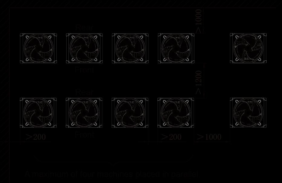
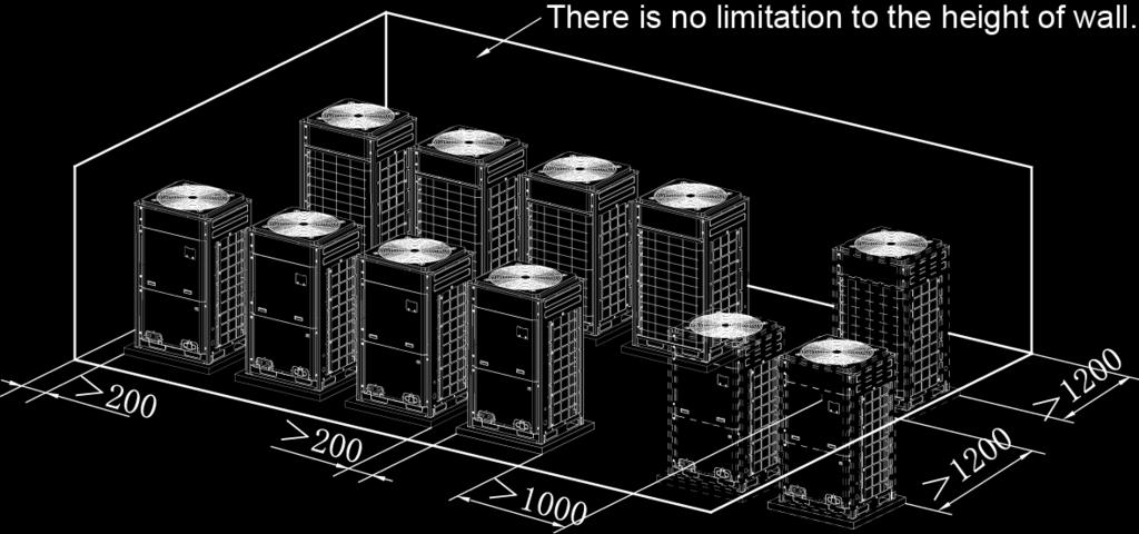
33 Installation space requirement for quad-module unit Figure 6 2. In principle, if a crown wall (obstacles for keeping out the wind) exists over the machine, a distance of at least 3000 mm should be left between the top of the machine and the crown wall. If the front, rear, left and right sides of the machine are open spaces, the distance between the top of the machine and the crown wall should be at least 1500 mm, as shown in Figure 7. If the requirement for the minimum 1500 mm cannot be met, or the spaces around the machine are not open, an air return pipe needs to be connected to maintain smooth ventilation, as shown in Figure 8. Figure 7 Figure 8 Installation space requirement for multiple ODUs To ensure smooth ventilation, the top of the unit must be open spaces without obstacles. If the front and left (or right) sides of the ODU are open spaces, the units should be installed along the same or reverse direction. 29


34 30


35 3. Monsoons must be considered during ODU installation. 4. Snow must be considered during ODU installation. 5. During the installation of the ODU, induced and exhaust pipes must be connected. In addition, the aperture opening rate of shutters must be at least 80%, and the angle between the shutters and the horizontal plane should be less than 20. Requirements for installing exhaust air duct are as follows: i. Basic requirement for connecting an ODU to static pressure ventilating duct 31

36 When an ODU needs to be connected to the static pressure ventilating duct, the ventilating duct must be reasonably designed. The pressure loss caused by the ventilating duct must be calculated. In addition, a proper type of ventilating duct is necessary. To connect he static pressure ventilating duct to the ODU, three basic parts are required: (1) ODU; (2) canvas; and (3) steel-plate ventilating duct. The ODU must be interconnected with the ventilating duct through canvas to prevent abnormal vibration and noise generated by the steel-plate ventilating duct. The joint part must be tightly sealed with tin foil to avoid air leakage. ii. Preparations for connecting an ODU to static pressure ventilating duct (1) The ODU is installed properly based on the unit installation requirement. (2) The steel-plate ventilating duct is designed based on the unit and engineering requirement, and is installed properly according to the engineering standards. (3) Based on the unit dimensions and the size of steel-plate ventilating duct, prepare materials such as canvas casing, tin foil, steel bar and tapping screw, as well as tools such as hand-operated electric drill, air screw driver and screwdriver. iii. Basic operation of connecting an ODU to static pressure ventilating duct Two methods are available to connect an ODU to static pressure ventilating duct. Method 1: Reserve the unit top case. Detailed operations are as follows: a) Install the ODU (2) and steel-plate ventilating duct (1). Use an air screw driver or screwdriver to unfasten the tapping screws that fixing the top case component (3), and then remove the top case component. Take out the grille from the top of the top case component and leave the top case. b) Put the canvas casing inside out (4). Cover one end of the canvas casing over the unit downward until the canvas end face is aligned with the unit or a bit higher than the top of the unit. Then, put the top case back (3) and tightly press the canvas casing (4). Use tapping screws to fix the top case onto the unit (3). c) Pull up the canvas casing reversely (4) and use the steel bar (5) to press the canvas casing tightly onto the counter flange of the steel-plate ventilating duct (1). Use a hand-operated electric drill to drill holes and fasten the parts by using tapping screws. d) Use the tin foil to seal the joints and check the joints' reliability. Step 1 Step 2 32
 to cover the surroundings over the top of the unit.")
37 Step 3 Step 4 Step 5 Step 6 Method 2: Remove the unit top case. Detailed operations are as follows: (1) Install the ODU (2) and steel-plate ventilating duct (1). Take out the grille from the top of the top case component. Use the prepared canvas casing inside out (4) to cover the surroundings over the top of the unit. Keep the top of canvas casing (4) 30 to 50 mm higher over the top of the unit. (2) Use a steel bar to press tightly the canvas casing (4) around the top case of the unit. Use a hand-operated electric drill to drill holes and fasten the canvas casing onto the unit through steel bar by using tapping screws. (3) Pull up the canvas casing reversely and use the steel bar to press the canvas casing tightly onto the counter flange of the steel-plate ventilating duct. Use a hand-operated electric drill to drill holes and fasten the parts by using tapping screws. (4) Use the tin foil to seal the joints and check the joints' reliability. Note: Remove the grille on the top case when connecting an ODU to static pressure ventilating duct; otherwise, the air volume, especially the unit operating performance will be affected. For method 2, since drills are required on the top case, the powder coated protective layer on the top case will be damaged. As a result, the anti-corrosion performance of the unit top case will be reduced. 33

38 Step 1 Step 2 Step 3 Step 4 6. When the effective area of air intake is less than 70% of the total air intake area of all ODUs, an induced draft fan is also required. The total air input of induced draft fan should be no less than 80% of the total supply air rate. 4 Installation Space Requirement for Mode exchangers 4.1 Dimension of Outdoor Unit and Mounting Hole Position Unit outline dimension: NCHS1B outline and installation dimension 34
39 NCHS4B outline and installation dimension NCHS8B outline and installation dimension 35
40 After the unit is installed, a service port should be reserved at the electric box side of unit for maintenance. The position of service port should be lower than the lower size of unit. The mode exchangers shall be installed near the service port or air return of indoor unit. (Note: if it is installed near the air return, please make sure not to affect air return and maintenance). The following pictures describe the installation of service port and mode exchangers: 36

41 Due to the structure of installation space, the mode exchangers need a service port. Please reserve another service port for mode exchangers. 37
42 48 Installation, Commissioning, and Maintenance Manual for Export-oriented GMV5 DC Inverter VRF Units 4.2 Hole-drilling for Bolt and Bolt Installation (1)Stick the installation template at the installation position flatly, drill 4 holes at the installation position basing on the installation template. As shown in fig Please refer to the diameter of expansion bolt for the diameter of hole with depth of 60-70mm. As shown in fig Fig Fig (2) Insert M10 expansion bolt into hole, and then set the iron nail into bolt. As shown in fig Caution! The length of bolt should be selection according to the height of room. Bolt should be purchased by the user. 4.3 Hang unit Fig Hang the unit at the bolt on the ceiling of room. Please use special nut for securing the unit. I I 2:1 Fig
43 Caution: 1 Before operation, please prepare all pipelines (connection pipe, drainage hose) and wires (connection wire for wired controller, connection wire for indoor unit). 2 When drilling holes on ceiling (air return outlet or air outlet), you can need to reinforce the ceiling to prevent vibration. For details, please consult user or builder. 3 If the strength of the ceiling is not good, please install a beam bracket, and then put the unit on the beam bracket. 4.4 Horizontal alignment When indoor unit is installed, please perform horizontal inspection for the complete unit. The front side and back side of the unit must be places horizontally. The left side and right side of the unit should along water drainage direction with 1% gradient. See fig Fig Cautions for Installation (1). The mode exchanger must be installed by using hanger rod. During installation, the components must be kept vertically upright according to the indicated direction; (2). During installation, enough space shall be considered for removal of the components. The pipe shall not be jammed between the components. (3). The distance of the component to the indoor unit along the pipe shall not be higher than 5000mm; (4). The component shall be installed in a straight line to the inlet pipe and branch pipe (See schematics below): ME UNIT Branch pipe Plan view Wrong connection Branch pipe ME UNIT Plan view Branch pipe ME UNIT Top view Right connection 39

44 4.5 Air pipe installation 1) Rectangular air duct installation No Name Hanger rod Air return pipe Air-duct-type IDU Return air inlet Air duct Air outlet The proceeding figure shows the installation of back return air inlet. In practice, the down return mode can also be implemented. The installation method is similar to that of back return mode. The air pipe is rectangular air duct, connecting to the air inlet of the IDU. At least one air outlet must keep opening. Air outlet and return air inlet are connected with canvas (insulation type canvas). If static pressure and low noise are required, a plenum chamber should be connected between the air outlet and air pipe. The dimensions of air inlet of the plenum chamber are consistent with that of the air outlet. The plenum chamber and air outlet are connected with canvas. The air back return method is adopted. Spaces should be reserved within the ceiling air-duct-type IDU for installing the air return pipe. Larger dimensions of a return air inlet with a slower wind speed are better. 2) Round air duct installation No Name Hanger rod Air return pipe Air-duct-type IDU 40 Return air inlet Transient air pipe Note: 1. The maximum length of air pipe refers to the sum of the total length of the air duct at the farthest air outlet and the total length of the air return pipe at the farthest return air inlet. 2. For the unit with auxiliary electric heating, if the round air duct is to be connected, the linear length of the transient air pipe should be at least 200 mm. Installation procedure of round air duct Air duct Air outlet (1) Preset the round air outlet on the transient air pipe and fix the round air outlet with tapping screws. (2) Cover the transient air pipe on the air outlet of unit, and connecting them with rivets. (3) Cover the air duct on the round air outlet and fasten the connection. Until now, the round air duct is
45 successfully connected to the unit. Other steps are not described here. Part 4 Requirements on Foundation Installation 1 ODU Foundation The concrete foundation of the ODU must be strong enough. Ensure that the drainage is smooth and that the ground drainage or floor drainage is not affected. Requirements on the concrete foundation are as follows: A. The concrete foundation must be flat and have enough rigidity and strength to undertake the unit s weight during running. The height of the foundation is 200 mm to 300 mm, which is determined based on the size of the unit. B. The proportion of the cement, sand, and stone for the concrete is 1:2:4. Place 10 reinforced steel bars (φ10 mm) with a space between of 30 mm. C. Use the mortar to flatten the surface of the foundation. Sharp edges must be chamfered. D. When the foundation is built on a concrete floor, crushed stones are not required. But the foundation surface must be roughened. E. Clear the oil stains, crushed stones, dirt, and water in the reserved bolt hole of the foundation and install a temporary cover before installing bolts. F. Build a drainage ditch around the foundation to discharge the condensate water. G. If the air conditioner is installed on the roof, check the intensity of the building and take waterproof measures. H. If a u-steel foundation is adopted, the structure must be designed with sufficient rigidity and strength. Anchor bolt with a nominal diameter of 12 mm Minimum width: 100 mm 30 mm Proportion of the cement, sand, and stone for the concrete is 1:2:4. Drain tank: 100 mm 20 mm 200 mm~300 mm This distance is determined based on the actual size of the unit. Cement foundation diagram 2 ODU Fixing Fix the ODU to the foundation with four M12 bolts securely to reduce vibration and noise. 3 Vibration Reduction for ODU The ODU must be fixed securely. Apply a thick rubber sheet or corrugated damping rubber pad with thickness of 200 mm or more and width of 100 mm or more between the ODU and the foundation, as shown in the following figures. 41
46 42


47 Part 5 Piping Connection 1 Schematic Diagram of Piping Connection 2 Schematic Diagram of Piping Sequence GMV-Q224WM/B-X and GMV-Q280WM/B-X GMV-Q335WM/B-X, GMV-Q400WM/B-X and GMV-Q450WM/B-X 43


 Remarks Total length")
48 3 Allowable pipe length and drop height among indoor and outdoor units Y type branch joint is adopted to connected indoor and outdoor units. Connecting method is shown in the figure below Note: Length of one Y-type branch is equivalent to 0.5m. Distance from the first branch to the farthest indoor unit; Distance from the first branch to the nearest indoor unit; Length of indoor branch is equivalent to 0.5m. Length(m) Remarks Total length (actual length) of connection pipe 1000 L1+L2+L3+L4+ +L12+a11+b12+ +d21+d22 Length between outdoor unit Actual length 165 L 44
49 and the farthest indoor unit Equivalent length 190 Difference between the pipe length from the first indoor branch to the farthest indoor unit and the pipe length from the first indoor branch to the nearest indoor unit Length from the first indoor branch to the farthest indoor unit (1) Maximum height difference between indoor and outdoor units: H L12-L11 L7+L8+L10+D22 90 Maximum height difference between indoor units: h1 30 h1 Maximum height difference between mode exchangers: h2 Maximum length of Main pipe (2) 90 L1 30 h2 Note: (1)Normally, the pipe length from the first indoor branch to the farthest indoor unit is 40m. Under the following conditions, the length can reach 90m: 1)Actual length of pipe in total: L1+L2 2+L3 2+L4 2+ +L9 2+a11+b11+ +d21+d m; 2)Difference between the pipe length from the first indoor branch to the farthest indoor unit and the pipe length from the first indoor branch to the nearest indoor unit: L12-L11 40m. (2)When the maximum length of the main pipe from outdoor unit to the first indoor branch 90m, then adjust the size of high pressure gas pipe, gas pipe and liquid pipe of main pipe according to the following table. Outdoor model GMV-Q224WM/B-X GMV-Q280WM/B-X Diameter of low pressure gas pipe (mm) No need to enlarge pipe diameter No need to enlarge pipe diameter 45 Diameter of liquid pipe (mm) No need to enlarge pipe diameter Diameter of high pressure gas pipe (mm) No need to enlarge pipe diameter Φ12.7 Φ22.2 GMV-Q335WM/B-X Φ28.6 Φ15.9 Φ22.2 GMV-Q400WM/B-X Φ31.8 Φ15.9 Φ25.4 GMV-Q450WM/B-X Φ31.8 Φ15.9 Φ25.4 GMV-Q504WM/B-X Φ34.9 Φ19.05 Φ25.4 GMV-Q560WM/B-X Φ34.9 Φ19.05 Φ25.4 GMV-Q615WM/B-X Φ34.9 Φ19.05 Φ28.6 GMV-Q680WM/B-X No need to enlarge pipe diameter Φ19.05 Φ28.6 GMV-Q730WM/B-X Φ38.1 Φ22.2 Φ31.8 GMV-Q785WM/B-X Φ38.1 Φ22.2 Φ31.8 GMV-Q850WM/B-X Φ38.1 Φ22.2 Φ31.8 GMV-Q900WM/B-X Φ38.1 Φ22.2 Φ31.8 GMV-Q960WM/B-X Φ41.3 Φ22.2 Φ34.9 GMV-Q1010WM/B-X Φ44.5 Φ22.2 Φ34.9 GMV-Q1065WM/B-X Φ44.5 Φ22.2 Φ34.9 GMV-Q1130WM/B-X Φ44.5 Φ22.2 Φ34.9 GMV-Q1180WM/B-X Φ44.5 Φ22.2 Φ34.9 GMV-Q1235WM/B-X Φ44.5 Φ22.2 Φ34.9 GMV-Q1300WM/B-X Φ44.5 Φ22.2 Φ34.9
50 Outdoor model Diameter of low pressure gas pipe (mm) Diameter of liquid pipe (mm) Diameter of high pressure gas pipe (mm) GMV-Q1350WM/B-X Φ44.5 Φ22.2 Φ34.9 GMV-Q1410WM/B-X GMV-Q1460WM/B-X GMV-Q1515WM/B-X GMV-Q1580WM/B-X GMV-Q1630WM/B-X GMV-Q1685WM/B-X GMV-Q1750WM/B-X GMV-Q1800WM/B-X No need to enlarge pipe diameter No need to enlarge pipe diameter No need to enlarge pipe diameter No need to enlarge pipe diameter No need to enlarge pipe diameter No need to enlarge pipe diameter No need to enlarge pipe diameter No need to enlarge pipe diameter Φ25.4 Φ41.3 Φ25.4 Φ41.3 Φ25.4 Φ41.3 Φ25.4 Φ41.3 Φ25.4 Φ41.3 Φ25.4 Φ41.3 Φ25.4 Φ41.3 Φ25.4 Φ41.3 (3)If the length between indoor unit and its nearest branch is above 10m, then double the size of the liquid pipe of indoor unit (only for the pipe size that is less than or equal to 6.35mm). (4 ) If the height difference between indoor and outdoor units exceeds 90m, please consult the manufacturer for specific technical requirements. (5)If the diameter of module liquid pipe exceeds Φ22.2mm, please select the branch pipe sub-assy of model ML02R. 4 Connection Pipe among Outdoor Modules 46


51 Notes: When the distance between outdoor units exceeds 2m, U-type oil trap should be added at low-pressure gas pipe. A+B 10m. Pipe connection among ODUs must meet the following requirements: 47


52 5 Size requirement for branch pipe and piping (main pipe) 1. Connection sketch map of single-module system Connection sketch map of multi-module system 2. Select appropriate pipe between outdoor unit and the first indoor branch ( L ) as per the pipe size of 48
53 outdoor unit. Pipe size of basic outdoor module is shown as follows: between outdoor unit and the first indoor branch Basic module Low pressure gas pipe (mm) Pipe between outdoor unit and the first indoor branch Liquid pipe (mm) High pressure gas pipe (mm) GMV-Q224WM/B-X Φ19.05 Φ9.52 Φ15.9 GMV-Q280WM/B-X Φ22.2 Φ9.52 Φ19.05 GMV-Q335WM/B-X Φ25.4 Φ12.7 Φ19.05 GMV-Q400WM/B-X Φ25.4 Φ12.7 Φ22.2 GMV-Q450WM/B-X Φ28.6 Φ12.7 Φ For multi-module system, select appropriate branch ( M1 M2 M3 )connected to outdoor module as per the pipe size of basic outdoor module. Pipe size of basic outdoor module is shown as follows: Pipe between module and outdoor branch M1 M2 M3 Basic module Low pressure gas pipe (mm) Size of the pipe between module and outdoor branch Liquid pipe (mm) High pressure gas pipe (mm) GMV-Q224WM/B-X Φ19.05 Φ9.52 Φ15.9 GMV-Q280WM/B-X Φ22.2 Φ9.52 Φ19.05 GMV-Q335WM/B-X Φ25.4 Φ12.7 Φ19.05 GMV-Q400WM/B-X Φ25.4 Φ12.7 Φ22.2 GMV-Q450WM/B-X Φ28.6 Φ12.7 Φ22.2 Selection of branch Y1 Y2 of outdoor modules: Selection of branch of outdoor modules Module s capacity (C) 504 C Model ML01R 4. Size of connection pipe M4 between branches of each basic module Size of connection pipe between branches of each basic module is determined by the total rated capacity of upstream modules. Connection pipe M4 between branches of outdoor module Total rated capacity of upstream modules: Q (kw) Size of connection pipe between branches of outdoor module Low pressure gas pipe (mm) Liquid pipe (mm) High pressure gas pipe (mm) 22.4 Q Φ19.05 Φ9.52 Φ Q>22.4 Φ22.2 Φ9.52 Φ Q>28.0 Φ25.4 Φ12.7 Φ Q>40.0 Φ28.6 Φ12.7 Φ Q>45.0 Φ28.6 Φ15.9 Φ Q>68.0 Φ31.8 Φ19.05 Φ Q>96.0 Φ38.1 Φ19.05 Φ31.8 Q>135.0 Φ44.5 Φ22.2 Φ Size of connection pipe L between the terminal outdoor branch and the first indoor branch Connection pipe L between outdoor unit and the first indoor branch 49
54 Basic module (single-module system) Size of connection between outdoor unit and the first indoor branch Low pressure gas pipe (mm) Liquid pipe (mm) High pressure gas pipe (mm) GMV-Q224WM/B-X Φ19.05 Φ9.52 Φ15.9 GMV-Q280WM/B-X Φ22.2 Φ9.52 Φ19.05 GMV-Q335WM/B-X Φ25.4 Φ12.7 Φ19.05 GMV-Q400WM/B-X Φ25.4 Φ12.7 Φ22.2 GMV-Q450WM/B-X Φ28.6 Φ12.7 Φ22.2 GMV-Q504WM/B-X Φ28.6 Φ15.9 Φ28.6 GMV-Q560WM/B-X Ф28.6 Ф15.9 Φ28.6 GMV-Q615WM/B-X Ф28.6 Ф15.9 Φ28.6 GMV-Q680WM/B-X Ф28.6 Ф15.9 Φ28.6 GMV-Q730WM/B-X Ф31.8 Ф19.05 Φ28.6 GMV-Q785WM/B-X Ф31.8 Ф19.05 Φ28.6 GMV-Q850WM/B-X Ф31.8 Ф19.05 Φ28.6 GMV-Q900WM/B-X Ф31.8 Ф19.05 Φ28.6 GMV-Q960WM/B-X Ф31.8 Ф19.05 Φ28.6 GMV-Q1010WM/B-X Ф38.1 Ф19.05 Φ31.8 GMV-Q1065WM/B-X Ф38.1 Ф19.05 Φ31.8 GMV-Q1130WM/B-X Ф38.1 Ф19.05 Φ31.8 GMV-Q1180WM/B-X Ф38.1 Ф19.05 Φ31.8 GMV-Q1235WM/B-X Ф38.1 Ф19.05 Φ31.8 GMV-Q1300WM/B-X Ф38.1 Ф19.05 Φ31.8 GMV-Q1350WM/B-X Ф38.1 Ф19.05 Φ31.8 GMV-Q1410WM/B-X Ф44.5 Ф22.2 Φ38.1 GMV-Q1460WM/B-X Ф44.5 Ф22.2 Φ38.1 GMV-Q1515WM/B-X Ф44.5 Ф22.2 Φ38.1 GMV-Q1580WM/B-X Ф44.5 Ф22.2 Φ38.1 GMV-Q1630WM/B-X Ф44.5 Ф22.2 Φ38.1 GMV-Q1685WM/B-X Ф44.5 Ф22.2 Φ38.1 GMV-Q1750WM/B-X Ф44.5 Ф22.2 Φ38.1 GMV-Q1800WM/B-X Ф44.5 Ф22.2 Φ Branch selection of mode exchanger ( A1, A2) Select branch of mode exchanger as per total capacity of downstream indoor unit(s). Please refer to the following table. Model selection for branch A1 A2 of mode exchanger ; R410A refrigerant system Total Capacity of the Downstream Indoor Unit (X) Model Y-Type Branch Pipe X 56 56<X <X <X <X 960 FQ01Na/A FQ02Na/A FQ03Na/A FQ04Na/A FQ05Na/A 50
55 960<X <X FQ06Na/A FQ07Na/A 7. Piping size among upstream branches of heat pump mode exchanger ( n1 n2 n3 n4 ) Piping requirement among upstream branches of heat pump mode exchanger ( n1 n2 n3 n4 ) Total rated capacity of lower indoor units: X (kw) Size of connection pipe between branches of mode exchanger Low pressure gas pipe (mm) Liquid pipe (mm) High pressure gas pipe (mm) X 14.2 Φ19.05 Φ9.52 Φ <X 40 Φ28.6 Φ12.7 Φ <X 80.0 Φ28.6 Φ15.9 Φ <X 96.0 Φ31.8 Φ19.05 Φ <X Φ38.1 Φ19.05 Φ <X Φ44.5 Φ22.2 Φ Piping size among downstream branches of heat pump mode exchanger a h Total rated capacity of lower indoor units: X (kw) Size of piping between indoor branches Gas pipe (mm) Liquid pipe (mm) X 5.6 Φ12.7 Φ <X 14.2 Φ15.9 Φ <X 20 Φ19.05 Φ Branch selection of downstream indoor unit of mode exchanger ( B1 B2 ) R410A refrigerant system Total rated capacity of lower indoor units: X (kw) Model Y-type branch X 20.0 FQ01A/A 10. Piping size between mode exchanger and downstream indoor unit ( b c d g ) Total rated capacity of lower indoor units: X (kw) Piping size between indoor branches Gas pipe (mm) Liquid pipe (mm) X 5.6 Φ12.7 Φ <X 14.2 Φ15.9 Φ <X 20 Φ19.05 Φ Piping between indoor branch and indoor unit ( e, f, I, j ) Size of connection pipe between indoor branch and indoor unit should be consistent with the connection pipe of indoor unit. Piping between indoor branch and indoor unit e f i j Rated capacity of indoor units Size of connection pipe between indoor branch and indoor unit Gas pipe (mm) Liquid pipe (mm) C 2.8 Φ9.52 Φ <C 5.0 Φ12.7 Φ <C 14.0 Φ15.9 Φ <C 16.0 Φ19.05 Φ
56 Part 6 Pipe Installation and Insulation 1 Pipe Installation for the Cooling System 1.1 Precautions on Pipe Direction Design Refrigerant pipe layout must be designed in accordance with the following principles: 1) The air conditioning installation should not damage the bearing structure or the decorative style. Air conditioning pipes should be laid out along the bottom of beam as possible. If pipes meet one another at the same elevation, process based on the following principles: Drain pipes enjoy the highest priority. Air ducts and pressure pipes should leave places for gravity pipes. Air ducts and small pipes should leave places for major pipes. 2) The refrigerant pipe layout must be optimal in actual engineering with minimum pipe length and bends. In this way, the performance of the unit can be maximized. 3) The refrigerant pipe cannot affect air discharge and return of internal units. The minimum distance between the refrigerant pipe with an insulation layer and the air return box is 300 mm. If the air return or manhole is at the right lower part of the unit, the minimum distance is 150 mm. When the refrigerant pipe needs to be laid at the air outlet side, avoid laying the pipe at the front of the air outlet. The refrigerant pipe cannot connect to any part of the unit except the joint points. If the preceding principles are not followed, performance of the unit will be affected and running noises will be increased. 4) The refrigerant pipe must be laid away from the manhole of the unit so that sufficient space can be reserved for maintenance. 5) The riser should be installed in the air conditioning tube well, and the horizontal pipe should be placed in the ceiling, if possible. 1.2 Processing to Refrigerant Pipes Cut-off and Burring Use a special-purpose pipe cutter to cut copper pipes instead of using a hacksaw. Cut the pipes gently to ensure that the copper pipe does not deform. 52
57 After cutting the pipes, use a slicker to grater bur the pipes with the pipe opening inclining downward so that the copper scales do not fall into the pipe. Allowable deviation: Skewness of the cross section cannot exceed 1% of the copper pipe caliber. If the copper pipe is not used immediately after cut-off, cover it with a sealing cap or adhesive tape Pipe Cleaning Cleaning with a piece of silk cloth: Wrap a thin steel wire with a piece of clean silk cloth. Crumple the cloth into a lump with diameter larger than the pipe calibre. Apply several drops of chlorylene to the cloth. Push the cloth in from one end of the pipe and pull out from the other end. Every time the cloth is pulled out, remove the dust and sundries with chlorylene. Wash repeatedly until the pipe is clean. This method applies to straight pipes. Cleaning with nitrogen: Blow off all dust and sundries in the pipe with nitrogen. This method applies to coils. After cleaning, cover the both ends of the pipe with a sealing cap or adhesive tape Pipe Bending Processing methods: Manual bending: applies to thin copper pipes (Φ6.35 mm to Φ12.7 mm) Mechanical bending: applicable range (Φ6.35mm to Φ54.1mm) Requirements: The radius of the bending pipe must exceed 3.5D. The ratio of the short diameter after bending to the original diameter must exceed 2/3. Precautions: During bending, there must be no corrugation or deformation inside the pipe. The welding point of the pipe should not be at the bending part. The distance between the nozzle welding joint and the bending part should be less than 100 mm Pipe Expanding Pipe expanding is used to provide a welding point for pipe connection. Requirements on pipe expanding are as follows: 1) All burrs and sundries inside the pipe must be cleared after cut-off. 2) Before pipe expanding, apply appropriate amount of lubricant on the surface of the pipe. (The lubricant must meet the refrigerant system s requirements.) 3) Pipe expanding length must be in accordance with the insertion depth of the caliber. 4) To avoid leakage due to straight lines at the expanding point, turn round the copper pipe and then make corrections. 5) Apply appropriate force during pipe expanding to avoid crack Flaring Another mode of pipe connection is flare opening connection, which requires pipe flaring before connection. Before pipe flaring, apply appropriate amount of lubricant on the surface of the opening to ensure smooth pass of flaring nuts and avoid pipe distortion. (The lubricant must meet the refrigerant system s requirements.) The concentricity must be ensured after pipe flaring. The sealing face must be intact without any burr, crack, or wrinkle. Requirements on pipe flaring are as follows: 1) End faces of the copper pipe are smooth. 2) Burrs and turnups inside the pipe opening must be cleared. 53
58 3) Install flaring nuts in the pipe before pipe flaring. 4) The flared opening must be concentric with the main pipe. No eccentricity is allowed. 5) Put the pipe into the root of the pipe expander. 6) Longitudinal cracks cannot be generated. 1.3 Installation of Refrigerant Pipes Operation Sequence The sequence for installing the refrigerant pipe is as follows: Preparing and installing the support, hanger, and bracket Piping according to the drawing Cleaning the pipe Processing the pipe Adding an insulation sleeve Connecting the pipe Fixing the pipe Blowing contaminants in the pipe system Performing a air-tightness test Performing insulation Construction of Built-in Metal Fittings Construction of supports, hangers, and brackets for pipes: These parts must be fixed securely in reasonable type and style without any tilt. The surface is clean without any dirt. The parts embedded into the wall or floor cannot be painted or coated and must be free from grease stains. Construction of fixing bolts for devices: Ensure sufficient rigidity for the devices. Take anticorrosive measures for exposed part of built-in fittings. If the foundation must be waterproof, takes waterproof measures. Construction of steel casings: Equip a steel casing for all pipes which are led through the wall or floor. Pipe welding joints cannot be placed inside the sleeve. The steel casing must be parallel with the bottom of the wall or floor but be 20 mm or more above the bottom. The diameter of the steel casing must be determined based on the thickness of the insulation layer and the inclination degree of the condensate water pipe. Fill the gap between the pipe and the sleeve with flexible and non-flammable materials. The sleeve cannot be used as a support point of the pipe. Operation Sequence Drawing of builtin metal fittings Making ink lines Installing built-in metal fittings If possible, make ink lines on the ground and project them to the top of the building. Installing Built-in Metal Fittings Select built-in metal fittings in accordance with local regulations. Installing Expansion Bolts Use expansion bolts when built-in metal fittings are unavailable due to design change. Installing Expansion Bolts If the foot pedal is 2 m or more from the ground, there must be three points of support. The foot pedal must be tightened securely with the ladder. Do not perform operations on the top of the ladder Shaping and Fixing of Pipes When installing refrigerant pipes, ensure that the directions and branches are correct with minimum length. Use minimum number of braze welding junctions and elbows. Alignment and insulation after installation cannot affect the pipe location and elevation. There shall not be flat bending or corrugation on the pipe after piping. Use angle steel support, bracket, round steel hanger, U-type pipe clip, or flat steel to fix pipes outside the insulation layer. It is better that the insulation materials be not compressed to ensure good insulation. 54
 ф 16 40>ф 19.")
59 The style and workmanship of supports, hangers, and brackets must follow the standard T616 HVAC Systems Design Handbook. The minimum distance between supports, hangers, and brackets is listed in the table below: External Diameter of the Pipe (mm) ф 16 40>ф ф 40 Distance between Horizontal Pipes (mm) Distance between Vertical Pipes (mm) The pipe led through a wall or beam must be fixed by a support, hanger, or bracket on both ends at the position 300 mm away from the hole Pipe Connection Flaring Connection The refrigerant pipes and IDUs are connected by using the flare opening. Therefore, the quality of flaring connection must be ensured. The flaring depth of the bell mouth cannot be smaller than the caliber. The flaring direction must face towards the direction of medium flow. Use two torque wrenches to fasten the connection Socket Welding The gap between socket components should be proper to ensure that the connection will not loose from the friction surface. The flaring direction of the socket component must face towards the direction of medium flow.during pipe connect, protect the braze welding part according the length specified below: A: External Diameter of the Pipe (mm) Bell Socket Welding B: Minimum Insertion Depth (mm) 55 D-A: Gap between Pipes (mm) ф ф ф12.7 ф ф19.05 ф ф25.4 ф28.6, ф ф38.1 ф ф The bell socket welding is another form of socket welding. It uses the sleeve or pipe in a larger size for welding. The insertion depth cannot be smaller than that required by socket welding Flange Connection The pipes with large caliber and the devices are always connected by using a flange, which must be clean and intact. Before installation, apply lubricant on the surface of the flange. Two flanges must be symmetrical.
 and must be regulated based on the pipe caliber. 1.3.")

60 Fasten with screws at the diagonal direction to avoid inclination Welding Protection Aerate with nitrogen before and during welding and keep aerating for 30 s after the welding is finished. Equip a pressure regulator valve to the nitrogen cylinder. The nitrogen flow is above 4-6 L/min (pressure of 0.02 to 0.05 MPa) and must be regulated based on the pipe caliber Requirements on Manifold Installation Manifolds are used to divert refrigerant. Requirements on manifold installation are as follows: A. Ensure that the manifold is close to the IDU to reduce impact on refrigerant assignment by IDU branches. B. The manifold must be that specified by the manufacture and match with the devices. C. Ensure that the manifold model is correct. D. Manifolds can be laid in the following ways: D1. Horizontal installation: The three ports must be on the same level. The shaping size and assembly angle cannot be changed. D2. Vertical installation: The direction can be upwards or downwards. Three ports must be on the same elevation without inclination. D3. The length of a straight pipe between two manifolds cannot be less than 500 mm. D4. The length of a straight pipe before the main pipe port of the manifold cannot be less than 500 mm. D5. The length of a straight pipe between the branch of the manifold and the IDU cannot be less than 500 mm. E. Fixing of manifolds. There must be three fixing point for both horizontal and vertical installation of the Y-type manifold. Fixing point 1: 100 mm on the main inlet manifold from the welding point Fixing point 2: 200 mm on the main branched pipe from the welding point Fixing point 3: 250 mm on the branched pipe from the welding point 56


61 Branches of a manifold must be laid parallel and cannot be wrapped in superimposed mode. F. The liquid pipe and gas pipe must have the same length and be laid in the same route. G. The Y-type manifold has an attached pipe used to adjust the diameter of different pipes. If the pipe size on site does not match the size of the manifold junction, use the pipe cutter to cut at the middle of the pipe and remove burrs. Then insert the copper pipe to proper depth. A concave bag for positioning is available to the manifold purchased from Gree. H. Because the manifold structure is complex, perform with care to ensure tight insulation Pipe Cleaning by Nitrogen Before connecting the flare opening of the pipe to the IDU, connect the pressure regulator valve on the nitrogen cylinder to the liquid pipe in the outdoor pipe system. Regulate the nitrogen pressure to about 5 kgf/cm² and blow nitrogen into the pipe for 1 minute. Repeat this operation for three times till the dirt and water are discharged. After cleaning the liquid pipe, perform the same operation to clean the gas pipe. finished. Perform an air-tightness test and a vacuum test to the entire refrigerant pipe system after the construction is There must be a secure distance between pipes. Pipes in different types must be fixed separately During refrigerant pipe installation, ensure a distance above 500 mm between the pipe and the electric box of the unit for maintenance. In a case when the space is not enough, the final piping way must be determined by the 57

62 technical personnel. Filter and Drier Installation for the ODU As the piping for the VRF system is complex, it is recommended that a filter is installed for the gas pipe and a drier is installed for the liquid pipe during construction. This ensures aridity and cleanness of the piping system and further improves the operation stability of the system. The procedure is as follows: First, weld a stop valve with the corresponding caliber to the gas pipe and liquid pipe at the position relatively close to the ODU and easy for operation. Second, install a filter (100 mesh/ft2) between the added stop valve outside the gas pipe and the stop valve of the ODU. Then install a drier filter between the added stop valve outside the liquid pipe and the stop valve of the ODU. Lastly, after the test run is complete, To remove the filter from the gas pipe after starting all IDUs and keeping them running cooling mode for 24 hours: (1) Power off all units. (2) Turn off the two stop valves of the gas pipe. (3) Remove the filter. (4) Short connect with a copper pipe with the same caliber and vacuumize the pipe. (5) Open the two stop valves and keep normal running. To remove the drier filter from the liquid pipe after starting all IDUs and keeping them running in heating mode for 24 hours: (1) Power off all units. (2) Turn off the two stop valves of the liquid pipe. (3) Remove the drier filter. (4) Short connect with a copper pipe with the same caliber and vacuumize the pipe. (5) Turn on the two stop valves and keep normal running. 58

63 2 Pipe Installation for the Condensate Water System 2.1 Pipes Generally, U-PVC water supply pipes bonded with special glue are adopted as condensate water pipes. PP-R, PP-C, and hot galvanized steel pipes can also be adopted. Aluminium plastic compound pipes cannot be used. 2.2 Requirements on Installation 1. Determine the direction and elevation of a condensate water pipe before installing it. Avoid overlapping it with other pipes to ensure straight inclination. The clamp of the pipe hanger is fixed outside the insulation layer. The height of the clamp can be adjusted. 2. Distance between Hangers External Diameter of the Pipe (mm) Distance between Horizontal Pipes (mm) Distance between Vertical Pipes (mm) There are at least two hangers for each vertical pipe. Φ 25 32>Φ 25 Φ The inclination degree of the condensate water pipe must be above 1% and that of the main pipe cannot be lower than 0.3%. Adverse slopes are not allowed. 4. When connecting three-way pipes, the two-way straight pipes must be laid on the same slope, as shown in the following figures. 5. The condensate water pipe cannot be tied with the refrigerant pipe. 6. A ventilation hole must be provided on the top of the drain pipe to ensure smoother discharge of condensate water. 7. After pipes are connected, perform a test with some water and another test with full water in the pipe to check whether drainage is smooth and whether water leakage exists in the pipe system. 8. Equip a steel casing for all pipes which are led through the wall or floor. Pipe bonding joints cannot be placed inside the sleeve. The steel casing must be parallel with the bottom of the floor or wall. There must be a height drop of 20 mm from the ground when the pipe is lead through the floor. The sleeve cannot affect the inclination degree of the pipe. Fill the gap between the pipe and the sleeve with flexible and non-flammable materials. The sleeve cannot be used as a support point of the pipe. 9. Bond the insulation material joints with special glue and then wrap them with plastic adhesive tape. The width of the adhesive tape must be 5 cm or more to prevent dewing. 59

64 2.3 Other Requirements 1. Ensure an inclination degree of more than 1% when connecting the drain pipe to the IDU. 2. When connecting the drain pipe to that of the IDU, fix the pipes with the bands provided upon delivery instead of using the glue to facilitate further maintenance. 3. When connecting the drain pipe branches to the main pipe, lead through from the above part of the main pipe. 4. If the air volume of the IDUs is high and outdoor air resorption may be caused by negative suction pressure, provide a u-type drain trap at the water outlet side of each IDU, as shown in the following figure. Install drain trap connectors as shown in the following figure. Install a drain trap connector for each unit. The drain trap connector shall be installed in a way that facilitates trap cleaning. Connector Indoor unit Indoor unit Connector 5. During condensate water pipe installation, ensure a distance above 500 mm between the pipe and the electric box of the unit for maintenance. In a case when the space is not enough, the final piping way must be determined by the technical personnel. 2.4 Requirements on Installation of Drain Pipes for Different Types of IDUs Drain Pipe Installation for Hidden Air-duct-type IDU for Air Supply 60


65 a. Ensure an inclination degree of greater than 1% when connecting the drain pipe to the IDU. b When connecting the drain pipe to that of the IDU, fix the pipes with the bands instead of using the glue to facilitate further maintenance. c. There is a condensate water outlet on both sides of the IDU. After one condensate water outlet is determined, use the rubber stopper to block the other outlet. Tie it with threads and strap with insulation materials to prevent leakage. d. The connection between the drain pipe and that of the IDU is shown in the following figure. e. Apply insulation materials to the condensate water pipe joints to prevent dewing. d. Insulation for connection between the drain pipe and that of the IDU is shown in the following figure Drain Pipe Installation for IDU a. Use pipe clips instead of applying glue to connect the hoses provided upon delivery and plastic pipes on the device. Connect the other end of the joint to the elbow. The height from the suction inlet of the discharge pump is about 200 to 500 mm. Ensure a proper inclination degree while connecting to the main drain pipe. b. The lifting pipe for drainage must be provided as shown in the following figure. c. The drain pump shall be fixed securely. Otherwise, abnormal noises will be generated. 61
66 2.5 Requirements on Independent Drainage for Each IDU Requirements on independent drainage design for each IDU are as follows: a. There must be a proper inclination for the drain pipe. b. The drain pipe must be installed to facilitate drainage to the largest extent and be as short as possible. c. If the water is discharged to the outdoor side, it cannot drop to the outdoor ground directly. 2.6 Requirements on Centralized Drainage for IDUs a. When there are multiple IDUs in the same building, centralized drainage is adopted. b. When a header pipe is used, the drain pipe of each IDU must be higher than the header pipe. c. The diameter of the header pipe must be determined on the number and capacity of IDUs. d. When installing pipe, start from the highest point of the pipe and follow the specified inclination to smoothly discharge condensate water. e. Connect branches to the main pipe from the upper part or side instead of lower part of the main pipe. f. Insulate all condensate water pipes, especially for joints at elbows. 3 Insulation System 3.1 Insulation for the Refrigerant Pipe System Insulation Materials Use closed-cell foam insulation materials with flame retardant grade of B1. The heat conductivity is not greater than w/(m k) when the average temperature is 0 C Thickness of the Insulation Layer External Diameter of the Pipe (mm) Thickness of the Insulation Layer (mm) Use sunblock, anti-weathering, and non-cracking insulation materials for outdoor pipes Procedure of Insulation a. Select insulation materials based on design requirements. b. Wear the insulation sleeve before connecting refrigerant pipes. Users cannot cut the insulation material apart and then wrap up with ties after connecting the pipes by welding. c. Specifications of the insulation sleeve must match with that of the refrigerant pipes. d. Reserve a distance of about 200 mm near the welding point to protect the insulation sleeve during welding. After performing the air-tightness test, perform insulation to the welding point separately to ensure continuity of the insulation sleeve. e. The insulation layer cannot crack during construction. Bond the insulation material joints with special glue and then wrap them with electrical adhesive tape. The width of the adhesive tape must be 50 mm or more to ensure secure connection. f. Use glue to bond the insulation material at the water outlet to the unit to prevent dewing. g. Wrap joints of indoor/outdoor units with insulation materials. There must be no gap between the joint and the wall of the indoor/outdoor unit, as shown in the following figure. 62
67 No gap 3.2 Insulation for the Condensate Water Pipe System a. Insulation Materials Use closed-cell foam insulation materials with retardant grade of B1. The heat conductivity is not greater than w/(m k) when the average temperature is 0 C. b. Thickness of the Insulation Layer Thickness of the insulation layer for the condensate water pipe must be greater than 10 mm. c. Bond the insulation material joints with special glue and then wrap them with plastic adhesive. The width of the adhesive must be greater than 5 cm to prevent dewing. d. Insulation is not required for the outdoor part of condensate water pipes. 3. Insulation for Air Ducts a. Insulation for air duct components and devices must be performed after the air leakage test is performed or after quality check. b. Use centrifugal glass wool or rubber and plastic materials for insulation or use novel insulation air ducts. c. The insulation layer should be flat and tight without any crack or gap. d. Thickness of the Insulation Layer For the air supply and return air pipe laid in a room without an air conditioner, thickness of the rubber and plastic insulation layer is 35 mm. For the air supply and return air pipe laid in an air conditioning room, thickness of the rubber and plastic insulation layer is 20 mm. e. Supports, hangers, and brackets of the air duct must be installed outside the insulation layer. A chock must be provided between the support, hanger, or brackets and the air duct. Part 7 Electric and Controller Installation 1 Precautions Both the power cable and communication cable must be connected properly. If the power cable is connected to the communication port, the main board will be burnt. The power cable and communication cable can be identified in the following ways: Method 1: Use sheaths in different colours. 63
68 1. Reliable grounding is required. 2. The screw for fixing the conducting wire must be tightened. It must be replaced if slipped screw head exists. 3. The external conducting wire must be fixed by a clip. Otherwise, personal injury or fire may occur. 1. Reliable grounding is required. 2. The screw for fixing the conducting wire must be tightened. It must be replaced if slipped screw head exists. 3. The external conducting wire must be fixed by a clip. Otherwise, personal injury or fire may occur. 1. Reliable grounding is required. 2. The screw for fixing the conducting wire must be tightened. It must be replaced if slipped screw head exists. 3. The external conducting wire must be fixed by a clip. Otherwise, personal injury or fire may occur. 1. Reliable grounding is required. 2. The screw for fixing the conducting wire must be tightened. It must be replaced if slipped screw head exists. 3. The external conducting wire must be fixed by a clip. Otherwise, personal injury or fire may occur. Installation, Commissioning, and Maintenance Manual for Export-oriented GMV5 DC Inverter VRF Units Single-phase unit Three-phase unit L N D1 D2 H1 H2 D1 D2 H1 H2 L N Grounding screw Warning Indoor/outdoor unit Wired controller communication D1 D2 H1 H2 Grounding screw Warning Indoor/outdoor unit Wired controller communication D1 D2 H1 H2 Color label for the communication cable Color label for the communication cable Color label for the power cable Power cable Indoor/outdoor Communication cable communication cable of the wired controller Color label for the power cable Power cable Indoor/outdoor communication cable Communication cable of the wired controller Method 2: Use different types of cables. The diameter of the power cable is larger than that of the communication cable. Alternatively, adopt three cores or more for the power cable and two cores for the communication cable. Single-phase unit Three-phase unit L N D1 D2 H1 H2 D1 D2 H1 H2 L N Grounding screw Warning Indoor/outdoor unit communication D1 D2 Wired controller H1 H2 Grounding screw Warning Indoor/outdoor unit communication D1 D2 Wired controller H1 H2 Power cable (three-core) (The yellow green cable is the ground cable.) Indoor/outdoor communication cable (two-core) Communication cable of the wired controller (two-core) Power cable (five-core) (The yellow green cable is the ground cable.) Indoor/outdoor communication cable (two-core) Communication cable of the wired controller (two-core) Elaborate the method with the installation personnel on site no matter which method is adopted. 2 Installation of the Power Cable 2.1 Precautions 1. The air conditioning unit is category 1 electrical appliance which requires reliable grounding. 2. The grounding resistance must meet the requirement of local law. 3. The yellow green cable inside the air conditioning unit is a grounding cable. It cannot be used for other purposes or be cut off. Do not fix it with tapping screws. Otherwise, an electric shock may be caused. 4. A reliable ground terminal must be provided for the power. Do not connect the grounding cable to any of the following: 5. a. Water pipes b. Gas pipes c Drainage pipe d. Other places deemed as unreliable 6. The power cable and the communication cable must be laid separately with a distance of greater than 20 cm. Otherwise, the communication of the unit will be affection. 2.2 Requirements on Power Cable Configuration Configure a circuit breaker to each unit for short circuit and overload protection. In addition, configure a general circuit breaker to both the indoor and ODUs to switch on or switch off the general power of the IDU or ODU. 1) External Connection for Individual Units 64

69 Note: The maximum number of connected IDUs (n) is determined based on the capacity of the ODU. For details, see the description on unit capacity configuration. 2) External Connection for Modularly Connected Units 65
 Knock off the knockouts used for threading the external power cable, fit the threading rubber ring to the hole, and thread the power cable through the")
70 Note: The maximum number of connected ODUs (N) and that of connected IDUs (n) are determined based on the combination form of ODUs. For details, see the description on unit capacity configuration. 2.3 Procedure for Installing the Power Cable 1) Knock off the knockouts used for threading the external power cable, fit the threading rubber ring to the hole, and thread the power cable through the hole. Connect L1, L2, L3, and N of the power cable, and the grounding cable to L1, L2, L3, and N on the power terminal block and the grounding screw next to the terminal block respectively. 66
 Lay the power cable and communication cable for the ODU according to the following figures.")


71 2) Fasten and fix the power cable with ties (support heads). 3) Lay the power cable and communication cable for the ODU according to the following figures. Note: Provide a threading rubber ring when threading a strong power cable or a communication cable. 3 Installation of the Communication System The CAN communication network is adopted for GMV5 VRF system. Manual DIP or identification on polarities of the communication power is not required for the IDU. Only the function DIP needs to be set for the ODU. For details, see the description on function setting of the ODU. 67


72 3.1 Connection of Communication Cable Terminals All connections for communication of GMV5 are fastened by screws. 3.2 Connection of Communication Cables The communication bus of indoor and ODUs must be connected in series instead of in star mode. The last IDU of the bus shall be connected to a matching resistor (placed in the package of the ODU). 68
73 LO1 LO2 LO3 Li1 Li2 Lin Li1 Li2 Lin Li1 Li2 Lin 69


74 LO1 LO2 LO3 Li1 Li2 Lin Li1 Li2 Lin Li1 Li2 Lin Communication cable connection for IDUs and ODUs 3.3 Connection Methods and Procedure of Communication System Connection of communication between indoor and outdoor units Communication between indoor and outdoor units is connected via terminal D1/D2 on the terminal block XT2. Connection method for single-module and multi-module systems is shown below: Connection of communication for single-module system and single-moudle exchangers system 70

75 Connection of communication for multi-module system and multi-module exchangers system 71


76 Communication cable connection for the multi-module system Note: 1 For modular outdoor units, if there are multiple outdoor modules, the master unit must be the first outdoor module on the communication wire and cannot be connected to indoor units. (The master unit i s set by SA8 on the main board of outdoor unit.) 2 For modular outdoor units, if there are multiple outdoor modules, indoor units must be connected to the last outdoor slave module. 3 Communication wire and power cord must be laid separately to avoid interference. 4 Communication wire shall be long enough. It s not recommended to connect wire by peeling away its outer layer. 5 Heat pump mode exchanger must be connected in series and the last mode exchanger must be connected with a matching resistance (provided among the accessory parts of outdoor unit). Connect the matching resistance to the D1, D2 terminals of wiring board XT1 of mode exchanger. 6 Adopt the one-to-one connection method for the connection between heat pump mode exchanger s and downstream indoor unit. Each branch is corresponding to one communication terminal. 1D1,1D2 indicates the terminal position of communication wire for the downstream indoor unit of the first branch; 2D1, 2D2 indicates the terminal position of communication wire for the downstream indoor unit of the second branch and by this analogy. Please note that there s corresponding mark at the corresponding connection place of copper pipe for each indoor unit on branch. 72
77 7 If there re multiple indoor units at one branch of heat pump mode exchanger, the communication wires of indoor units should adopt series connection. Please note that operation mode for the indoor units at the same branch should be consistent under any circumstances. 8 Communication wire can t be connected for the downstream indoor units at the different branches of heat pump exchangers Connection of communication between indoor unit and wired controller below: There are 4 connection methods for communication between indoor unit and wired controller, as shown One wired controller controlling one IDU Two wired controllers controlling one IDU One wired controller controlling multiple IDUs 73
78 Two wired controllers controlling multiple IDUs When two wired controllers control multiple IDUs, the wired controllers can be connected to any IDU which is in the same series. Set of the two wired controller to the secondary wired controller. The number of IDUs controlled by the wired controller cannot exceed 16. All connected IDUs must be in the same network. The secondary wired controller can be set in start-up or shutdown mode. 1 Press the FUNCTION button for 5 seconds on the wired controller to be set as the secondary wired controller. The temperature area displays C00. Continue to press the FUNCTION button for 5 seconds, the parameter setting interface is displayed and the temperature area displays P00. 2 Select code P13 by pressing or. Press the MODE button to switch to parameter value setting. When the parameter value flickers, select code 02 by pressing or. Then press the ENTER/CANCEL button to finish setting. 3 Users can press the ENTER/CANCEL button to return to the previous level till parameter setting exits. The parameter setting list is shown below: Parameter Code Parameter Name Parameter Range Default Value Remark P13 Wired controller address setting 01: primary wired controller 02: Secondary wired controller 01 When two wired controllers control one or multiple IDUs, the addresses of the controllers must be different. The secondary wired controller (address: 02) does not support unit parameter setting except setting of its address. 74


79 MAX NO. SET CHECK AUTO TURBO MIN ON OFF DAY HOUR SAVE CLEAN E-HEATER X-FAN FRESH AIR DEFROST SHIELD GROUP MEMORY MASTER ENTER/ CANCEL SLEEP FAN MODE FUNCTION TIMER SWING ON/ OFF Note: 1 All wired controllers are set to primary wired controllers upon delivery. 2 In parameter setting status, Fan, Timer, Sleep, and Swing buttons are unavailable. Press the ON/OFF button to return to the home page without executing the action of power-on or power-off. 3 In parameter setting status, the remote controller signal is unavailable Connection between the air duct type IDU and receiver board When the air duct type IDU needs to be connected to the remote-control receiver board, connect via Dsp1 and Dsp2 on the main board of the IDU. Remote-control Receiver IDU Type Board Duct type indoor unit JS03 Connection Type Inter-board connection (17 cores) Corresponding Main Board Interface of the IDU Dsp1 (interconnecting with the 8-core interface) Dsp 2 (interconnecting with the 9-core interface) Note: 1 The wired controller and the remote-control receiver board can be used at the same time. 2 When selecting the remote-control receiver board, select a remote controller. 75
80 3.3.4 Communication connection for units with central control Below is the connection of terminal G1 and G2 on terminal block XT2 of master unit of each multi VRF system. When installing long-distance monitor or centralized controller, indoor unit project code offset operation is required. For detailed operation methods, please refer to Installation, Commissioning and Maintenance Manual for Heat Recovery Units. 3.4 Installation and Disassembly of the Wired Controller (See the Manual) XK46 Wired Controller Basic parameters and components of the wired controller 76


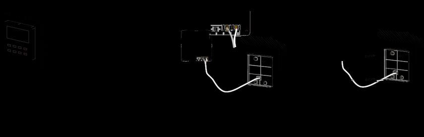
81 No Name Panel of wired controller Screw M4*25 Soleplate of wired controller Quantity Installation of the wired controller Disassembly of the wired controller 77


 Quantity Provided by users 1 2 1")
82 3.4.2 XK49 Wired Controller Basic parameters and components of the wired controller Figure 3.1 Size of the wired controller Installation of the wired controller Figure 3.2 Components of the wired controller SN Name Connecting box installed in the wall (86 Base plate of the wired controller Screw M4X25 Wired controller panel box) Quantity Provided by users Installation diagram of the wired controller 78
83 Notes: A. The wired controller must be installed by professional personnel. The power must be switched off during installation. B. Pull out the two-core twisted-pair communication cable connected to the IDU from the installation hole in the wall and connects it to H1 and H2 of the terminal block and screws it on. C. Precautions for the door control system If the wired controller is not connected to the door control system, set the switch 1 of the DIP S1 on the base plate to the digit. To connect the wired controller to the door control system, set the switch 1 of the DIP S1 on the base plate to ON and connect the door control card interface to interfaces N and L or interfaces VCC and GND of the terminal block. Note: Interfaces N and L are door control power interfaces with V-50/60 Hz. Interfaces VCC and GND are door control power interfaces with DC 5-24 V. Users can select only one from V and DC 5-24 V. D. After cable connection is finished, cling the base plate of the wired controller to the wall and use the screw M4X25 to fix the base plate to the installation hole in the wall. E. Insert the inter-board connection cable of the base plate to the needle file CN1 of the wired controller panel. Then place the panel and base plate together. Disassembly of the wired controller Disassembly diagram of the wired controller Part 8: Vacuumization and Desiccation for the Refrigerant System Works for the refrigerant system include cleaning and desiccating the pipes, performing an air-tightness test, and perfusing refrigerant. 1 Air-tightness Test 1. Importance of the Air-tightness Test Air-tightness of the multi-module air conditioning system mainly refers to the tightness of the refrigerant pipes, which ensures secure and reliable running of the air conditioner. Refrigerant leakage may affect functions of the air conditions or even damage the compressor and make the system to break down. Therefore, a air-tightness test must be performed. If refrigerant leakage is detected after the system is installed, it is very difficult to locate the leaking point as the suspending ceiling has been decorated. 79

84 Therefore, the air-tightness test must be performed before ceiling sealing for indoor decoration is finished. 2. Procedure for Performing the Air-tightness Test Stop valves of the gas and liquid pipes of the ODU are turned off at delivery. Before test, apply a small amount of required lubricant on the block nut and pipe terminals and use two wrenches to fix the block nut. The ODU pipes cannot be connected when the air-tightness test is being performed. The test pressure for R410A system is 4.0 MPa. Use dry nitrogen as media for the air-tightness test. Increase the pressure slowly by following the steps below: Step 1: Increase the pressure to 0.5 MPa. Stop for 5 minutes and then perform air-tightness check. Major leakage may be detected. Step 2: Increase the pressure to 1.5 MPa. Stop for 5 minutes and then perform air-tightness check. Minor leakage may be detected. Step 3: Increase the pressure for R410A system to 4.15 MPa. Stop for 5 minutes and then perform strength check. Slight leakage or blow holes may be detected.after increasing the pressure to the test pressure, keep the pressure for 24 hours and check whether it decreases. If the pressure does not decrease, it meets the requirement. 3. Precautions: a. The measuring range of the test pressure gauge for R410A system must be above 4.5 MPa. b. Record the value displayed on the pressure gauge, ambient temperature, and test time. c. Pressure correction: The pressure changes by 0.01 MPa when the temperature changes by 1 C. d. The pressure meets the requirement if it does not change. e. If the pressure must be kept for a long time, decrease the pressure to 0.5 MPa or lower. High pressure for a long time may cause leakage at the welding point or safety hazard. f. Before performing the air-tightness test to the refrigerant pipes, do not conduct insulation or wrapping at the welding or flaring opening joints of the IDU. The pressure must be increased simultaneously for pipes on outdoor sides and cannot be increased for pipes on one side. 4. Note: Before performing the air-tightness test, do not conduct insulation or wrapping at the welding joints. 2 Vacuumization and Desiccation for the System 1. Requirements on the Vacuum Pump The vacuum pump for different refrigerant systems cannot be the same. The ultimate vacuum degree of the vacuum pump should reach -0.1 MPa. The air discharge capacity of the vacuum pump must be greater than 4 L/S. The precision of the vacuum pump must be greater than 0.02 mmhg. The system vacuum pump must be equipped with a check valve. 80


85 2. Procedure and Precautions for Vacuumization and Desiccation 2.1 Procedure a. Before vacuumization, ensure that the stop valves of the gas and liquid pipes are turned off. b. Use the perfusing duct to connect the regulator valve and vacuum pump to detection connectors of the gas pipe and liquid pipe. c. Vacuumize for 4 hours and check whether the vacuum degree reaches -0.1 MPa or more. If not, leakage may exist. Perform leakage check again. If no leakage exists, continue to vacuumize for 2 hours. If the vacuum degree cannot be kept after vacuumization is performed for twice, there may be water in the pipe when it is confirmed that no leakage exists. In this case, discharge water by means of vacuum breaking. Perfuse nitrogen at 0.05 MPa to the pipe. Vacuumize for 2 hours and keep vacuuming for 1 hour. If the vacuum degree of -0.1 MPa cannot be reached, repeat this operation till water is discharged. After vacuumization, turn off the regulator valve and keep for 1 hour. Ensure that the pressure of the regulator valve does not increase Precautions: a. 1Before vacuum pumping, make sure that outdoor unit s liquid valve, high pressure gas valve and low pressure gas valve are completely closed. Use vacuum pump to extract air inside indoor unit and connection pipe from the nozzles of liquid valve, high pressure gas valve and low pressure gas valve of outdoor unit, as shown in figure Because air extraction from outdoor unit s liquid valve, high pressure gas valve and low pressure gas valve must be performed simultaneously, 2 sets of vacuum pump must be used at the same time to guarantee the required vacuum degree. Figure 2-1 Figure 2-2 b. Turn off the valve before powering off the vacuum pump. c. Keep vacuuming for 2 hours. The vacuum meets the requirement if the pressure displayed by the vacuum gauge does not increase. d. The units parallel connected to the module and oil-equalizing pipe also need to be vacuumized. Part 9: Refrigerant Perfusion 1 Calculation Method for Perfusing Refrigerant Quantity of refrigerant perfused for the pipe (R) = Quantity of refrigerant perfused for the pipe (A) + 81
86 Quantity of refrigerant perfused for each module (B) 1. Method for calculating the quantity of refrigerant perfused for the pipe (A): Quantity of perfused refrigerant for the pipe (A) = Length of the liquid pipe x Quantity of perfused refrigerant for the liquid pipe per meter Diameter of the Liquid Pipe Φ28.6 Φ25.4 Φ22.2 Φ19.05 Φ15.9 Φ12.7 Φ9.52 Φ6.35 kg/m B (Quantity of refrigerant added to each module) is calculated as below: Quantity of refrigerant added to each module (kg) 2 Indoor/outdoor unit rated capacity allocation ratio: C 1 50% C 70% 70% C 90% 90%<C 105% 105%<C 135% Sets of allocated indoor unit Module capacity (kw) sets >4 sets sets >4 sets sets >4 sets sets >4 sets Note: (1) Rated capacity configuration rate C for IDUs and ODUs = Sum of rated cooling capacity of IDUs/Sum of rated cooling capacity of ODUs (2) If all IDUs are fresh air IDUs in GMV-NX series, the quantity of refrigerant perfused for each module (B) is 0 kg. For example: Example 1: The outdoor units are composed of 3 modules: GMV-Q280WM/B-X, GMV-Q400WM/B-X, GMV-Q450WM/B-X. The indoor units are 8 sets of GMV-ND140PLS/A. In this case, C (Indoor/outdoor unit rated capacity allocation ratio) = 140 9/( )=112%, and there are more than 4 sets of indoor unit. According to the table above, The quantity (B) of refrigerant added to GMV-Q280WM/B-X is 3.5kg; The quantity (B) of refrigerant added to GMV-Q400WM/B-X is 5.0kg; The quantity (B) of refrigerant added to GMV-Q450WM/B-X is 5.0kg So, B (Quantity of refrigerant added to each module) = =13.5kg Suppose that A (Quantity of refrigerant added to connection pipe) = Length of liquid pipe x Quantity of refrigerant added to liquid pipe per meter) = 25kg R (Quantity of added refrigerant in total) = =38.5kg Example 2: The outdoor unit is made up of 1 module: GMV-Q450WM/B-X. The indoor unit is 1 set of fresh air indoor unit: GMV-NX450P/A(X4.0). In this case, the quantity (B) of refrigerant added to this module is 0kg. So, B (Quantity of refrigerant added to each module) = 0kg Suppose that A (Quantity of refrigerant added to connection pipe) = Length of liquid pipe x Quantity of 82
87 refrigerant added to liquid pipe per meter) = 5kg R (Quantity of added refrigerant in total) = 5+0=5kg 2 Method for Perfusing Refrigerant Refrigerant perfusion for the VRF system is classified into pre-perfusion and perfusion during running. 1. Refrigerant Pre-perfusion Step 1: Connect the high pressure gauge pipe to the detection opening of the liquid pipe, and the medium gauge pipe to the vacuum pump. Power on the vacuum pump to perform vacuumization and desiccation. Step 2: After vacuumization and desiccation are finished, turn off valves of the high pressure gauge and low pressure gauge. Disconnect the medium gauge pipe from the vacuum pump and connect it to the refrigerant tank. Step 3: Properly loosen the joint between the medium gauge pipe and the pressure gauge and slightly turn on the valve of the refrigerant tank. Vacuumize the medium gauge pipe. After that, fasten the joint and turn on the valve of the refrigerant tank completely. Step 4: If the refrigerant tank is not equipped with a siphon, reverse the refrigerant tank and place it on the electronic scale. Then record the current weight (m1). If the refrigerant tank is equipped with a siphon, record the current weight (m1) directly. 83
88 Step 5: Turn on the valve of the high pressure gauge (while keep the valve of the high pressure gauge turned off) and then perfuse refrigerant to the system. Record the change of weight of the refrigerant tank. Step 6: When all refrigerant in the refrigerant tank is perfused, record the current weight m2. Step 7: Turn off the valve of the high pressure gauge and replace the refrigerant tank. Step 8: Perform step 3 again. Step 9: Perform step 5 and step 6 again. Record the weight before perfusion m3 and weight after perfusion m4. Step 10:If there is no sufficient refrigerant and the calculated quantity of refrigerant is not fulfilled for the system, record the current total perfusion quantity. m=(m1-m2)+(m3-m4)+ +(mn-1-mn) Quantity of refrigerant to be perfused during running m`=m-m M is the required total quantity If the pre-perfusion quantity (m) reaches the required total quantity for the system, turn off the valve of the refrigerant tank immediately to finish perfusing and proceed with step 11. Step 11: Remove the pressure gauge. 2. Refrigerant Perfusion during Running Step 1: Turn off the valve of the refrigerant tank and reconnect the pressure gauge pipe. Disconnect the low pressure gauge pipe from the detection valve opening of the gas liquid and connect it to the low pressure detection valve, as shown in the following figure. 84
89 Step 2: Turn on the valves for the liquid and gas pipes of each module completely. For the modular unit, the oil-equalizing valve of each module also needs to be turned on. Step 3: Make the system to run in commissioning mode via the commissioning software or the main board of the ODU. (For details, see the description on commissioning.) Step 4: When the commissioning step goes to refrigerant perfusion, turn on the valve of the refrigerant tank and perfuse the remaining quantity (m`). Step 5: After all refrigerant is perfused, turn off valve of the refrigerant tank and wait till commissioning is automatically is completed for the system. Step 6: Remove the pressure gauge to finish refrigerant perfusion. 85
90 Chapter 3 Commissioning Operation Part 1 Security Requirements 1 Precautions for Construction 1. All commissioning and maintenance personnel must learn and strictly comply with construction security specifications. Security measures must be taken especially for outdoor operations. 2. Workers of special types of labor, such as refrigerating engineers, electricians, and welders, must have professional certificates. No worker is allowed to do another type of labor. 3. The equipment must be powered off before relevant operations, and other security requirements should be strictly complied with. 4. All installation and maintenance operations must comply with design requirements of this product and national and local security operation requirements. Rule-breaking operations are prohibited. 2 Precautions for the Use of Refrigerants The GMV5 serial unit is a refrigerating system of R410A working substances. Pay attention to the following points: 1. The refrigerating system of R410A working substances has a higher working pressure than that of R22 working substances. The working pressure of the former is 1.6 times than that of the latter. 2. The refrigerating system of R410A working substances uses thicker-walled copper tubes than that of R22 working substances. Adopt copper tubes with appropriate wall thickness. 3. R410A working substances are azeotropic mixture working substances. Refrigerants must be appended in the form of liquid. Part 2 Introduction to Unit Functions 1 Function Settings of ODUs Function application of ODUs consists of function DIP switch settings and function button settings, including special engineering requirements. 1.1 System Function DIP Switch Settings 86
91 DIP Switch Name Meaning Factory Settings Remark SA1_capacity SA2_Addr-CC SA3_COMP-E SA4_I/M-E SA5_FAN-E SA6_ESP_S Capacity DIP switch Centralized control address DIP switch 2#-6# compressor emergency operation DIP switch 1# compressor/module emergency operation DIP switch Fan emergency operation DIP switch Outdoor fan static pressure setting DIP switch Defines the rated capacity of the unit. Defines and differentiates addresses of different systems in the case of centralized control by multiple systems. Provides aftersales emergency settings for 2#-6# compressors. Provides aftersales emergency settings for 1# compressor/module. Provides aftersales emergency settings for fans. Sets the static pressure of the fan according to the static pressure of the exhaust pipeline connected with the engineering unit, to guarantee normal operation of the unit. Defined based on the model SA7 Reserved DIP switch 00 SA8_MASTER -S Master unit setting DIP switch Defines the master unit The factory settings cannot be changed. The address DIP switch is used only when centralized control is required. Otherwise, the factory settings are used without being changed. The address DIP switch is valid only when it is set on the master unit. It is better not to use the emergency function. Replace the compressor at the first time when an exception occurs. It is better not to use the emergency function. Replace the compressor at the first time when an exception occurs. It is better not to use the emergency function. Replace relevant parts of the fan at the first time when an exception occurs. This DIP switch should be set based on actual engineering conditions, neither over-large nor over-small. It is unnecessary to change the factory settings in outdoor scenarios. A master unit must be set, and only one master unit can be set in each refrigerating system. This DIP switch is mandatory. The default factory setting is the master unit status. Note: On the master module, the SA8 DIP switch must be set again, the SA1 DIP switch cannot be further set, and other DIP switches retain the factory settings without special requirements. Function DIP switches must be set when the ODU is powered off, and then the settings are valid after the ODU is powered on. Meanings and setting methods of function DIP switches are as follows: (1) Unit Capacity DIP Switch (SA1_capacity) The unit capacity DIP switch (SA1_capacity) has been set upon factory departure. It is unnecessary to further set the DIP switch. In addition, users are not allowed to change the DIP switch settings. Otherwise, the system may work abnormally or even the compressor may be damaged. (2) Centralized Control Address DIP Switch (SA2_Addr-CC) The centralized control address DIP switch (SA2_Addr-CC) indicates the centralized control address 87
92 required when different refrigerating systems are controlled in a centralized manner. The default factory setting is "00000". If it is not required to use centralized control between multiple refrigerating systems, this DIP switch can retain the factory settings without being changed. If it is required to use centralized control between multiple refrigerating systems, set the DIP switch according to the following methods: 1) The DIP switch must be set on the master unit. Otherwise, the setting is invalid. 2) On the same refrigerating system, the centralized control address DIP switch (SA2_Addr-CC) on a non-master unit is invalid, and it is unnecessary to change the settings. 3) The centralized control address DIP switch (SA2_Addr-CC) on the master unit of a refrigerating system must be set to 00000, and this system is the master system. 4) The centralized control address DIP switch (SA2_Addr-CC) on the master unit of other refrigerating systems must be set as follows: SA2 Address DIP1 DIP2 DIP3 DIP4 DIP5 No ) The centralized control address DIP switch (SA2_Addr-CC) cannot be the same between different refrigerating systems. Otherwise, address conflicts may occur and the unit cannot run properly. (3) Compressor Emergency Operation DIP Switch (SA3_COMP-E) Corresponding to 2#-6# compressors, the compressor emergency operation DIP switch (SA3_COMP-E) is used for aftersales emergency settings when an exception occurs on a compressor. It can shield the operation of the abnormal compressor in a short time and guarantee the emergency operation of other compressors. When it is required to shield the operation of 2#-6# compressors upon failure, set the DIP switch according to the following methods: Compressor Emergency Operation DIP Switch (SA3_COMP-E) DIP1 DIP2 DIP3 DIP4 DIP Remark Not shielding the operation of 2#-6# compressors Shielding the operation of 2# compressor Shielding the operation of 3# compressor Shielding the operation of 4# compressor Shielding the operation of 5# compressor Shielding the operation of 6# compressor
93 occur. Precautions: A. When the DIP switch setting is not covered in the above scope, a DIP switch setting exception fault may B. Only one compressor can be set to emergency mode on a module. C. The compressor emergency operation mode is valid only in a single-module multi-compressor system. D. The default factory setting is E. The system cannot continually run for more than 24 hours in compressor emergency operation status. Once 24 hours are exceeded, the entire unit will be forcibly stopped and the limited operation code Ad is displayed on the IDU. F. 1#-6# compressors are defined from right to left facing the front of the unit. (4) 1# Compressor/Module Emergency Operation DIP Switch (SA4_I/M-E) The 1# compressor/module emergency operation DIP switch (SA4_I/M-E) is used for aftersales emergency settings when an exception occurs on the 1# compressor/module. It can shield the operation of the abnormal compressor/module in a short time and guarantee the emergency operation of other compressors. occur. When it is required to set the 1# compressor/module to emergency mode, set the DIP switch as follows: 1# Compressor/Module Emergency Operation DIP Switch (SA4_I/M-E) DIP1 DIP2 Remark 0 0 Not shielding the operation of 1# compressor/module 1 0 Shielding the operation of 1# compressor 0 1 Shielding the operation of the module Precautions: A. When the DIP switch setting is not covered in the above scope, a DIP switch setting exception fault may B. Only one compressor can be set to emergency mode on a module. Subsequent to emergency operation, valves of shielded outdoor unit, including the gas pipe, liquid pipe and oil balance pipe, need to be closed tight by hand. C. The compressor emergency operation mode is valid only in a single-module multi-compressor system. D. The module emergency operation mode is valid only in a system with more than two modules connected 89
94 in parallel. E. Only one module can be set to emergency operation mode in each system. F. The default factory setting is 00. G. The system cannot continually run for more than 24 hours in compressor emergency operation status. Once 24 hours are exceeded, the entire unit will be forcibly stopped and the limited operation code Ad is displayed on the IDU. H. The system cannot continually run for more than 48 hours in module emergency operation status. Once 48 hours are exceeded, the entire unit will be forcibly stopped and the limited operation code Ad is displayed on the IDU. I. 1#-6# compressors are defined from right to left facing the front of the unit. (5) Fan Emergency Operation DIP Switch (SA5_FAN-E) The fan emergency operation DIP switch (SA5_FAN-E) is used for aftersales emergency settings when an exception occurs on a dual-module fan. It can shield the operation of a fan in a short time and guarantee the emergency operation of the system. 1) Fan positions occur. 2) When it is required to set the fan to emergency mode, set the DIP switch as follows: Fan Emergency Operation DIP Switch (SA5_FAN-E) DIP1 DIP2 Remark 0 0 No fan in emergency operation mode 1 0 Shielding the operation of 1# fan 0 1 Shielding the operation of 2# fan Precautions: A. When the DIP switch setting is not covered in the above scope, a DIP switch setting exception fault may B. Only one fan can be set to emergency mode on a module. C. The default factory setting is 00. D. The system cannot continually run for more than 120 hours in fan emergency operation status. Once 120 hours are exceeded, the entire unit will be forcibly stopped and the limited operation code Ad is displayed on 90
95 the IDU. (6) Outdoor Fan Static Pressure Setting DIP Switch (SA6_ESP_S) The outdoor fan static pressure setting DIP switch (SA6_ESP_S) is used in special scenarios such as the unit installation equipment room. In scenarios where air ducts are required to be connected, zero static pressure (0 Pa), low static pressure (30 Pa), medium static pressure (50 Pa), and high static pressure (82 Pa) can be set according to the design of air ducts. The setting methods are as follows: Outdoor Fan Static Pressure Setting DIP Switch (SA6_ESP_S) DIP1 DIP2 Static Pressure Range The default factory setting is Pa Pa Pa Pa Note that the DIP switch should be independently set on each module. (7) Reserved Function DIP Switch (SA7) SA7 is the reserved function DIP switch and meaningless currently. (8) Master Unit Setting DIP Switch (SA8_MASTER-S) The master unit setting DIP switch (SA8_MASTER-S) defines module management of a system. A master unit must be set, and only one master unit can be set in each refrigerating system (in power-off status). The setting methods are as follows: Master Unit Setting DIP Switch (SA8_MASTER-S) DIP1 DIP2 Remark 0 0 Master unit 1 0 Sub-module Upon factory departure, all modules are in 00 master unit status by default. When multiple modules are connected in parallel, only one module retains the master unit status and other modules are set to sub-module status. When a module is independently used, it uses the factory settings. occur. For the basic module set to master unit, the module address is displayed as 01 on the main board. Precautions: A. When the DIP switch setting is not covered in the above scope, a DIP switch setting exception fault may B. A module must be set to master unit status, and only one module can be set to master unit status in each refrigerating system. Other modules are set to sub-module status. C. Settings must be performed in power-off status. D. The default factory setting is "00" master unit status. (9) DIP Switch Example A. Explanation of DIP switch positions On the DIP switch, ON indicates 0 status and the opposite direction indicates "1 status. The position of white lever indicates the position to be set to. 91

96 B. Example The following takes master unit settings as an example. Assume that a system consists of three modules: module a, module b, and module c. Set module c to master unit and the other two modules to sub-modules. The settings are as follows: 2 System Function Button Operations Module c (Master Module) Module a/module b (Sub-module) Note: System function settings and query must be performed after commissioning of the entire unit. System function settings and query can be used no matter whether the entire unit runs. 2.1 Introduction to Function Buttons The main board AP1 of the ODU consists of eight function buttons: Button Code Function Meaning Function Button Name and Meaning SW1 UP Indicates the upward selection button. SW2 DOWN Indicates the downward selection button. SW3 FUNCTION Indicates the function button, used for function settings. SW4 CHECK Indicates the query button, used for function query. SW5 SKIP Indicates the skip button. SW6 BACK Indicates the return button, used to return to the upper-level menu. SW7 CONFIRM Indicates the confirmation button. SW8 RESET Indicates the reset button, used to restore factory settings. 92
97 2.2 Introduction to Functions List of functions Function Code A2 A6 A7 A8 n0 n3 n4 n5 n6 n7 n8 n9 nb Function Name Refrigerant recovery operation Unit cooling/heating function Outdoor silent mode Aftersales vacuuming mode Conservation control 1 Forcible defrosting operation Conservation control 2 Indoor unit project number offset Fault query Parameter query Indoor unit project number query Online IDU quantity query Outdoor unit bar code function query Description of Functions (1) A2 Refrigerant recovery operation Function Meaning Fully or partially recovers refrigerants in a faulty module or IDU pipeline according to the system pressure after automatic startup during maintenance. Sets the unit to cooling/heating, single-cooling, single-heating, or air supply mode for centralized management. Sets different silent modes to meet users' noise requirements. Automatically enables all electronic expansion valves and electromagnetic valves during maintenance to guarantee vacuum processing in all pipelines. Automatically decreases the power consumption of the unit according to system operation parameters. Forcibly enables ODU defrosting operation. Forcibly decreases the maximum power consumption of the unit. Prevents IDU project number conflicts when different refrigerating systems are controlled in a centralized manner. Queries historical fault information of the ODU. Queries real-time operation parameters of the ODU. Displays project numbers of all IDUs through ODU operations. Displays the number of online IDUs. Queries the entire-unit bar code and controller bar code of ODU. Code Factory Settings Meaning na 00 Cooling/Heating function No silent settings 01 No automatic conservation settings 00 No capacity output limitation settings Remark It can only be set. It can be set and queried. It can be set and queried. It can only be set. It can be set and queried. It can only be set. It can be set and queried. It can only be set. It can only be queried. It can only be queried. It can only be queried. It can only be queried. It can only be queried. This function partially recovers refrigerants in a faulty module or IDU pipeline during unit maintenance. The 93
98 refrigerant recovery volume of each basic module is as follows: Model of Basic Module Maximum Refrigerant Recovery Volume (kg) GMV-Q224WM/B-X 7.5 GMV-Q280WM/B-X 7.5 GMV-Q335WM/B-X 8.7 GMV-Q400WM/B-X GMV-Q450WM/B-X 13.5 This function falls into two modes: faulty module refrigerant recovery and IDU pipeline refrigerant recovery. Refrigerant Recovery Refrigerant Recovery Remark Mode Code Mode Name pipeline. conflicts Basic module refrigerant recovery Indoor unit pipeline refrigerant recovery This mode is selected when a basic module fails and it is required to recover refrigerants from this basic module. This mode is selected when an IDU fails and it is required to recover refrigerants from the IDU pipeline. When this function is enabled, the ODU automatically starts and recovers refrigerants to the ODU or IDU (2) A6 Unit cooling/heating function This function sets operation modes of the entire unit, including: Function Mode of ODU Code na Name Cooling/Heating 94 Operation Mode of IDU Cooling mode, dehumidifying mode, heating mode, and air supply mode. (Note: The heating mode cannot work with other modes at the same time.) (factory settings) nc Single-cooling Cooling mode, dehumidifying mode, and air supply mode. nh Single-heating Heating mode and air supply mode. (Note: The heating mode cannot work with the air supply mode at the same time.) nf Air supply Air supply mode. The user or administrator can set operation modes of the ODU based on actual situations to prevent When it is required to set different refrigerating systems to the same function mode, set the master system according to the above requirements. For the master system settings, see the "Centralized Control Address DIP Switch (SA2_Addr-CC)" section. (3) A7 Outdoor silent mode This function is used when users require lower environment noises, including nighttime automatic silent mode and forcible silent mode. For the nighttime automatic silent mode, the system automatically judges the highest daytime environment temperature and then starts silent operations in a certain interval to guarantee nighttime low-noise operations. The nighttime automatic silent mode falls into nine categories: Silent Mode Code Starting the Silent Mode X Hours after the Daytime Temperature Reaches the Highest Stopping the Nighttime Silent Mode after Continual Operations for Y Hours Mode Mode Mode Mode Mode Mode Noise Degree Low-noise mode
99 Mode Mode Low- and medium-noise mode Mode superlow-noise mode Note: The highest daytime temperature is generally in 13:00-15:00. For the forcible silent mode, the system runs in low-noise mode no matter in the daytime or nighttime. The forcible silent mode falls in three categories: Silent Mode Code Noise Degree Mode Low-noise mode Mode Low- and medium-noise mode Mode superlow-noise mode Note: The system capacity may fall off after the silent mode is set. Therefore, try to balance the noise with the capacity in selecting a silent mode category. The factory setting is 00. (4) A8 Aftersales vacuuming mode This function ensures the vacuum degree of the entire system during maintenance to prevent operation functions of dead zones. Expansion valves and electromagnetic valves of the unit will be enabled after this function is set. (5) n0 Conservation control 1 System conservation is set when conservation operations are required. The default factory setting is capacity priority control mode. The system capacity may fall off after the conservation mode is set. (6) n3 Forcible defrosting operation Code Function Name 01 Conservation control invalid (factory settings) 02 Conservation control - valid This function is set when forcible defrosting is required for the unit during maintenance. After this function is enabled, the system automatically quits based on quitting conditions and then automatically runs based on system conditions. (7) n4 Conservation control 2 The highest capacity output limitation is set when users require forcibly limiting the system power consumption. The setting scope is as follows: Code Highest Output Capacity % (factory settings) 09 90% 08 80% Note: The cooling or heating effect may fall off after the capacity limitation is set. (8) n5 Indoor unit project number offset This function sets the IDU project number when multiple refrigerating systems are controlled in a centralized manner (by using a remote monitor or centralized controller), avoiding the same project number between different systems. If the project number is not set, project number conflicts may occur between systems. These function only needs to be set on the master system, which is the system with the centralized control address SA2 DIP switch being For details, see the "Centralized Control Address DIP Switch 95
100 (SA2_Addr-CC)" section. order. (9) n6 Fault query This function queries historical faults of the system. Up to five historical faults can be memorized in time (10) n7 Parameter query This function queries operation parameters of each module of the ODU in real time. (11) n8 Indoor unit address query This function queries addresses of all IDUs through one operation of the ODU. (12) n9 Online IDU quantity query This function queries the number of online IDUs through the ODU Function Setting Operations Step 1: Open the commissioning window of the master unit panel. Step 2: Power on the entire unit. Step 3: Press "SW3" on the master unit to enter the to-be-selected status of function settings. By default, the master unit is displayed as follows: LED1 LED2 LED3 Function Code Display Mode Current Progress Display Mode Current Status Display Mode A7 Blinking 00 Blinking 00 Blinking Users can select corresponding functions by pressing "SW1 (UP)" or "SW2 (DOWN)" on the master unit, including: LED1 LED2 LED3 Function Code Display Mode Current Progress Display Mode Current Status Display Mode A7 Blinking 00 Blinking 00 Blinking A6 Blinking 00 Blinking 00 Blinking A2 Blinking 00 Blinking 00 Blinking A8 Blinking 00 Blinking 00 Blinking n0 Blinking 01 Blinking 00 Blinking n3 Blinking 00 Blinking 00 Blinking n4 Blinking 00 Blinking 00 Blinking n5 Blinking 00 Blinking 00 Blinking After selecting the functions to be set, press "SW7" to confirm entering function settings. The master unit is displayed as follows: LED1 LED2 LED3 Function Code Display Mode Current Progress Display Mode Current Status Display Mode A7 On 00 Blinking OC Blinking A6 On nc Blinking nc Blinking A2 On 01 Blinking 00 Blinking A8 On 00 Blinking OC Blinking n0 On 01 Blinking OC Blinking n3 On 00 Blinking 00 Blinking n4 On 10 Blinking OC Blinking n5 On 00 Blinking OC Blinking Then go to step 4 to set corresponding functions. 96
101 Step 4: Set function parameters. Setting methods of function parameters are as follows: A7 Outdoor silent mode settings Step 1: Confirm entering the A7 outdoor silent mode settings. The master unit is displayed as follows: Function Code LED1 LED2 LED3 Display Mode Silent Mode Code 97 Display Mode Current Status Display Mode A7 On 00 Blinking OC Blinking Step 2: Select a corresponding silent mode by pressing "SW1 (UP)" or "SW2 (DOWN)". Function Code LED1 LED2 LED3 Display Mode Silent Mode Code Display Mode Current Status Display Mode A7 On 00 Blinking OC Blinking A7 On 01 Blinking OC Blinking A7 On 02 Blinking OC Blinking A7 On 03 Blinking OC Blinking A7 On 04 Blinking OC Blinking A7 On 05 Blinking OC Blinking A7 On 06 Blinking OC Blinking A7 On 07 Blinking OC Blinking A7 On 08 Blinking OC Blinking A7 On 09 Blinking OC Blinking A7 On 10 Blinking OC Blinking A7 On 11 Blinking OC Blinking A7 On 12 Blinking OC Blinking Step 3: Press "SW7" to confirm selecting the mode. The master unit is displayed as follows: Function Code LED1 LED2 LED3 Display Mode Silent Mode Code Display Mode Current Status Display Mode A7 On 00 On OC On A7 On 01 On OC On A7 On 02 On OC On A7 On 03 On OC On A7 On 04 On OC On A7 On 05 On OC On A7 On 06 On OC On A7 On 07 On OC On A7 On 08 On OC On A7 On 09 On OC On A7 On 10 On OC On A7 On 11 On OC On A7 On 12 On OC On On the master unit, press "SW6" to return to the upper level (press "SW6" in setting status to return to the upper level; press "SW6" after settings are completed to restore the normal operating status of the unit). If no button operations are performed on the master unit for five minutes, the function setting automatically
102 quits and the unit restores the current status. follows: The default factory setting is 00, that is, no silent mode. A6 Unit cooling/heating function settings Step 1: Confirm entering the A6 unit cooling/heating function settings. The master unit is displayed as Function Code LED1 LED2 LED3 Display Mode ODU Function Mode Code Display Mode ODU Function Mode Code Display Mode A6 On nc Blinking nc Blinking Step 2: Select a corresponding cooling/heating function by pressing "SW1 (UP)" or "SW2 (DOWN)". LED1 LED2 LED3 Function Code Display Mode ODU Function Mode Code Display Mode ODU Function Mode Code Display Mode A6 On nc Blinking nc Blinking A6 On nh Blinking nh Blinking A6 On na Blinking na Blinking A6 On nf Blinking nf Blinking Step 3: Press "SW7" to confirm selecting the mode. The master unit is displayed as follows: LED1 LED2 LED3 Function Code Display Mode ODU Function Mode Code Display Mode ODU Function Mode Code Display Mode A6 On nc On nc On A6 On nh On nh On A6 On na On na On A6 On nf On nf On On the master unit, press "SW6" to return to the upper level (press "SW6" in setting status to return to the upper level; press "SW6" after settings are completed to restore the normal operating status of the unit). If no button operations are performed on the master unit for five minutes, the function setting automatically quits and the unit restores the current status. follows: The default factory setting is na cooling/heating. A2 Refrigerant recovery operation settings Step 1: Confirm entering the A2 refrigerant recovery operation settings. The master unit is displayed as Function Code LED1 LED2 LED3 Display Mode Refrigerant Recovery Code 98 Display Mode Current Status Display Mode A2 On 01 Blinking 00 Blinking Step 2: The default setting is 01. Select "01" or "02" by pressing "SW1 (UP)" or "SW2 (DOWN)". Press "SW7" to confirm selecting the mode. On the master unit, press "SW6" to return to the upper level. If no button operations are performed on the master unit for five minutes, the function setting automatically quits and the unit restores the current status. Indoor unit refrigerant recovery
103 Step 3: Select "01 as in step 2 to enter IDU refrigerant recovery. Digital LEDs and status LEDs of all basic modules are displayed as follows: LED1 LED2 LED3 Function Code Display Mode Refrigerant Recovery Code Display Mode Current Status Display Mode A2 On 01 On [Module low-pressure Ps] On LED3 shows the low-pressure value of a module. If the value is negative, LED3 circularly displays the negative code "ne and the numeric value every one second. For example, for -30 C, LED3 alternately displays ne for one second and then 30 for another second. Step 4: Close liquid-tube stop valves of all basic modules of the ODU. When the low-pressure value displayed on LED3 continually blinks, quickly close air-tube stop valves of all basic modules and then press "SW7" on the master unit to confirm completing refrigerant recovery or power off the entire unit. If no operations are performed after the low-pressure value displayed on LED3 continually blinks for three minutes, the entire unit will be forcibly stopped. On the master unit, press "SW6" to return to the upper level for restoring the standby status of the entire unit (press "SW6" in setting status to return to the upper level; press "SW6" after settings are completed to restore the normal operating status of the unit). Note: Another startup is not allowed within 10 minutes after refrigerant recovery. Basic module refrigerant recovery Step 3: Set the basic module requiring refrigerant recovery to module emergency operation status and close the liquid-tube stop valve of the emergency status module. Select "02 as in step 2 to enter basic module refrigerant recovery. The display is as follows: Function Code LED1 LED2 LED3 Display Mode Current Progress 99 Display Mode A2 On 02 On LED3 shows the high-pressure value of the module. Current Status Module high-pressure Display Mode Step 4: When the high-pressure value displayed on LED3 continually blinks (displayed as 0 C if the high pressure is less than 0 C), quickly close the air-tube stop valve of the emergency module and then press "SW7" on the master unit to confirm completing refrigerant recovery or power off the entire unit. If no operations are performed after the high-pressure value displayed on LED3 continually blinks for three minutes, the entire unit will be forcibly stopped. On the master unit, press "SW6" to return to the upper level for restoring the standby status of the entire unit (press "SW6" in setting status to return to the upper level; press "SW6" after settings are completed to restore the normal operating status of the unit). Note: Before the basic module refrigerant recovery operation, users must close the liquid-tube stop valve of the basic module requiring refrigerant recovery. follows: Another startup is not allowed within 10 minutes after refrigerant recovery. A8 Aftersales vacuuming mode settings Step 1: Confirm entering the A8 aftersales vacuuming mode settings. The master unit is displayed as On
104 Function Code LED1 LED2 LED3 Display Mode Current Progress Display Mode Current Status Display Mode A8 On 00 Blinking OC Blinking Enter the to-be-confirmed status of system vacuuming mode settings. Step 2: Press "SW7" to confirm entering the to-be-confirmed status of system vacuuming mode settings. All modules are displayed as follows: Function Code LED1 LED2 LED3 Display Mode Current Progress Display Mode Current Status Display Mode A8 On 00 On OC On Expansion valves and electromagnetic valves of all outdoor and IDUs are opened, and the entire unit cannot be enabled. Press "SW6" on the master unit to quit the vacuuming status. Alternatively, the entire unit quits the vacuuming status after 24 hours. n0 System conservation operation settings Step 1: Confirm entering the n0 system conservation operation settings. The master unit is displayed as follows: LED1 LED2 LED3 Function Code Display Mode Code Display Mode Current Status Display Mode n0 On 01 Blinking OC Blinking Step 2: Select a corresponding mode by pressing "SW1 (UP)" or "SW2 (DOWN)". LED1 LED2 LED3 Function Code Display Mode Code Display Mode Current Status Display Mode n0 On 01 Blinking OC Blinking n0 On 02 Blinking OC Blinking Step 3: Press "SW7" to confirm selecting the mode. The master unit is displayed as follows: LED1 LED2 LED3 Function Code Display Mode Code Display Mode Current Status Display Mode n0 On 01 On OC On n0 On 02 On OC On If no button operations are performed for five minutes, the function setting automatically quits and the unit restores the current status. (Press "SW6" in setting status to return to the upper level; press "SW6" after settings are completed to restore the normal operating status of the unit.) n3 Forcible defrosting operation settings Step 1: Confirm entering the n3 forcible defrosting operation settings. The master unit is displayed as follows: LED1 LED2 LED3 Function Code Display Mode Current Progress/Mode Display Mode Current Status Display Mode n3 On 00 Blinking 00 Blinking Step 2: Press "SW7" to confirm entering forcible defrosting. The master module is displayed as follows: LED1 LED2 LED3 100
105 Function Code Display Mode Current Progress/Mode Display Mode Current Status Display Mode n3 On 00 On 00 On When the unit reaches defrosting quit conditions, the system automatically quits and restores the normal operation control. n4 Highest capacity output limitation settings Step 1: Confirm entering the n4 highest capacity output limitation settings. The master unit is displayed as follows: LED1 LED2 LED3 Function Code Display Mode Highest Output Capacity Display Mode Current Status Display Mode n4 On 10 Blinking OC Blinking Step 2: Select a corresponding capacity limitation value by pressing "SW1 (UP)" or "SW2 (DOWN)". LED1 LED2 LED3 Function Code Display Mode Highest Output Capacity Display Mode Current Status Display Mode n4 On 10 Blinking OC Blinking n4 On 09 Blinking OC Blinking n4 On 08 Blinking OC Blinking Step 3: Press "SW7" to confirm selecting the mode. The master module is displayed as follows: LED1 LED2 LED3 Function Code Display Mode Highest Output Capacity Display Mode Current Status Display Mode n4 On 10 On OC On n4 On 09 On OC On n4 On 08 On OC On If no button operations are performed on the master unit for five minutes, the function setting automatically quits and the unit restores the current status. (Press "SW6" in setting status to return to the upper level; press "SW6" after settings are completed to restore the normal operating status of the unit.) n5 Indoor unit project number offset settings Step 1: Confirm entering the n5 IDU project number offset settings. The master unit is displayed as follows: LED1 LED2 LED3 Function Code Display Mode Current Progress/Mode Display Mode Current Status Display Mode n5 On 00 Blinking 00 Blinking Step 2: Press "SW7" to send the project number offset command. The master module is displayed as follows: LED1 LED2 LED3 Function Code Display Mode Current Progress/Mode Display Mode Current Status Display Mode n5 On 00 On OC On After 10 seconds, the system quits this mode and restores the normal operation mode. Note: This function only needs to be set on the master system, which is the system with the centralized control address SA2 DIP switch being "00000". For details, see the "Centralized Control Address DIP Switch (SA2_Addr-CC)" section. 101
106 2.3 Function Query Operations Step 1: Open the commissioning window of the master unit panel. Step 2: Power on the entire unit. Step 3: Press "SW4" on the master unit to enter the query status. Step 4: Select a function to be queried by pressing "SW1 (UP)" or "SW2 (DOWN)" on the master unit. By default, the A7 outdoor silent mode is displayed for query. For example, select the A6 unit cooling/heating function. The display is as follows: LED1 LED2 LED3 Function Code Display Mode ODU Function Mode Code Display Mode ODU Function Mode Code Display Mode A6 On na On na On Step 5: If the n8 IDU address query is selected, the display is as follows. Enter the to-be-confirmed status of IDU project number query. LED1 LED2 LED3 Function Code Display Mode Current Progress/Mode Display Mode Current Status Display Mode n8 Blinking 00 Blinking 00 Blinking Press "SW7" and select the IDU project number query on the master unit. The master unit is displayed as follows. Other modules are displayed in normal status. LED1 LED2 LED3 Function Code Display Mode Current Progress/Mode Display Mode Current Status Display Mode n8 On 00 On 00 On Regardless of the current display status of wired controllers or display panels of all IDUs, the current display status is all switched to the IDU project number. However, it does not influence the settings and operation status of outdoor and IDUs. status. On the master unit, press "SW6" to return to the upper level. The IDU retains the project number display On the master unit, press and hold "SW6" to quit the address display status for all IDUs and return to the upper level. If no quit button operations are performed on the master unit for 30 minutes, the function setting automatically quits and the unit restores the current status. Step 6: If the n9 IDU address query is selected, the display is as follows: Function Code LED1 LED2 LED3 Display Mode Number of IDUs (Thousands-place Hundreds-place) 102 Display Mode Number of IDUs (Tens-place Ones-place) Display Mode n9 On 00 On 00 Blinking The digital LED2 displays the number of IDUs (thousands-place hundreds-place) and the digital LED3 displays the number of IDUs (tens-place ones place). For example, if the number of IDUs is 75, "0075" is displayed. If no button operations are performed on the master unit for five minutes, the function setting automatically quits and the unit restores the current status. Note: The online IDU quantity query function applies to a single refrigerating system only. Step 7: If the n6 fault query is selected, the display is as follows. Enter the to-be-confirmed status of fault query. LED1 LED2 LED3 Function Code Display Mode Current Progress/Mode Display Mode Current Status Display Mode n6 Blinking 00 Blinking 00 Blinking
107 Press "SW7" on the master unit to confirm fault query. Select a fault to be queried by pressing "SW1 (UP)" or "SW2 (DOWN)". LED3 alternately displays the historical fault code and module address in an interval of one second in the sequence of fault records. LED2 displays the fault sequence number. If there not historical faults, LED2 and LED3 display 00 by default. Up to five historical faults can be queried. The faults that can be queried are as follows: Code Code E1 High-pressure protection P9 Inverter compressor out-of-step protection E3 Low-pressure protection C2 Communication failure between the master unit and inverter compressor driver U4 Lack of refrigerant protection P8 Over-high temperature protection for inverter compressor driver module E2 Discharge low-temperature protection P7 Temperature sensor failure of inverter compressor driver module J9 Over-low pressure ratio protection PF Charge circuit failure of inverter compressor driver J8 Over-high pressure ratio protection HL DC bus line over-low voltage protection for inverter outdoor fan driver J7 Four-way valve leakage protection HH DC bus line over-high voltage protection for inverter outdoor fan driver E5 High-temperature protection of compressor Inverter outdoor fan driver IPM module H6 1 protection E6 High-temperature protection of compressor 2 HJ Inverter outdoor fan startup failure J2 Over-current protection of compressor 2 HE Inverter outdoor fan phase lack protection EU Top high-temperature protection of compressor 1 H3 Inverter outdoor fan driver module reset Eb Top high-temperature protection of compressor 2 H5 Inverter outdoor fan over-current protection PL DC bus line over-low voltage protection for Current detection circuit failure of inverter HC inverter compressor driver outdoor fan driver PH DC bus line over-high voltage protection for inverter compressor driver H9 Inverter outdoor fan out-of-step protection P6 Inverter compressor driver IPM module Communication failure between the master C3 protection unit and inverter outdoor fan driver PJ Inverter compressor startup failure H8 Over-high temperature protection for inverter outdoor fan driver module PE Inverter compressor phase lack protection H7 Temperature sensor failure of inverter outdoor fan driver module P3 Inverter compressor driver module reset Fd Malfunction of exit tube temperature sensor of mode exchanger P5 Inverter compressor over-current protection Fn Malfunction of inlet tube temperature sensor of mode exchanger PC Current detection circuit failure of inverter Communication malfunction between mode CE compressor driver exchanger and IDU qc Cooling code for main unit Cd Communication malfunction between mode exchanger and ODU qh Heating code for main unit Cn Malfunction of network for IDU and ODU of mode exchanger qa Code for heat recovery status Cy Communication malfunction of mode exchanger LU Indoor unit s branch is not inconsistent for one-to-more unit of heat recovery system The display is as follows: LED1 LED2 LED3 Function Display Fault Code Mode Sequence Display Mode Current Status Display Mode n6 On 01 On Displayed alternately n6 On 02 On Displayed alternately n6 Historical On 03 On Displayed alternately fault/module address n6 On 04 On Displayed alternately n6 On 05 On Displayed alternately 103
108 "01-05" indicates the fault sequence from the earliest to the latest. If there are less than five historical faults, LED2 and LED3 display 00 indicating there are no more historical faults after the last fault is displayed. In fault query status, press and hold "SW7" for five seconds to clear all historical faults of the ODU. Step 8: If the n7 parameter query is selected, the display is as follows. Enter the to-be-confirmed status of parameter query. LED1 LED2 LED3 Function Code Display Mode Current Progress/Mode Display Mode Current Status Display Mode n7 Blinking 00 Blinking 00 Blinking On the master unit, press "SW7" to confirm parameter query and enter the module confirmation status for parameter query. The display is as follows: LED1 LED2 LED3 Function Code Display Mode Module Address Display Mode Current Status Display Mode n7 On 01 Blinking 00 Blinking n7 On 02 Blinking 00 Blinking n7 On 03 Blinking 00 Blinking n7 On 04 Blinking 00 Blinking Select a module for parameter query by pressing "SW1 (UP)" or "SW2 (DOWN)" and then press "SW7". The display is as follows: LED1 LED2 LED3 Function Code Display Mode Parameter Code Display Mode Current Status Display Mode n7 On XX On Parameter value Blinking LED2 displays the parameter code of the module and LED3 displays the parameter value. Parameters are displayed in the following sequence. By default, the outdoor environment temperature value is displayed. Select a corresponding parameter value by pressing "SW1 (UP)" or "SW2 (DOWN)". Parameter Code Parameter Name Unit Remark 01 Outdoor environment temperature C 02 Operation frequency of compressor 1 Hz 03 Operation frequency of compressor 2 Hz 04 Operation frequency of outdoor fan Hz 05 Module high-pressure C 06 Module low-pressure C 07 Discharge temperature of compressor 1 C 08 Discharge temperature of compressor 2 C 09 Discharge temperature of compressor 3 C This parameter is invalid for the GMV5 series. 10 Discharge temperature of compressor 4 C This parameter is invalid for the GMV5 series. 11 Discharge temperature of compressor 5 C This parameter is invalid for the GMV5 series. 12 Discharge temperature of compressor 6 C This parameter is invalid for the GMV5 series. 13 Operation frequency of compressor 3 Hz This parameter is invalid for the GMV5 series. 14 Current value of compressor 1 A 104
109 Note: Installation, Commissioning, and Maintenance Manual for Export-oriented GMV5 DC Inverter VRF Units 15 Current value of compressor 2 A 16 Current value of compressor 3 A This parameter is invalid for the GMV5 series. 17 Current value of compressor 4 A This parameter is invalid for the GMV series. 18 Current value of compressor 5 A This parameter is invalid for the GMV5 series. 19 Current value of compressor 6 A This parameter is invalid for the GMV5 series. 20 Reserved 21 Module temperature of compressor 1 C 22 Module temperature of compressor 2 C 23 Module temperature of outdoor fan 1 C 24 Module temperature of outdoor fan 2 C 25 Outdoor unit heating EXV1 PLS 26 Outdoor unit heating EXV2 PLS 27 Subcooler EXV PLS 28 Defrosting temperature C 29 Liquid-extracting temperature of subcooler 30 Outlet temperature of accumulator C 31 Oil return temperature C This parameter is invalid for the GMV5 series. 32 Inlet-tube temperature of condenser C This parameter is invalid for the GMV5 series. C If a parameter value is negative, LED3 circularly displays the negative code "ne and the numeric value every one second. For example, for -30 C, LED3 alternately displays ne for one second and then 30 for another second. The discharge temperature and environment temperature are displayed as four-digit values, circularly displaying the higher two digits and the lower two digits. For example, if "01" and "15" are alternately displayed, it indicates 115 C. If "ne", "00", and "28" are alternately displayed, it indicates -28 C. If a parameter is invalid for the unit, 00 is displayed. If no button operations are performed on the master unit for five minutes, the function setting automatically quits and the unit restores the current status. Step 9: If the nb ODU bar code query is selected, the display is as follows. Enter the to-be-confirmed status of ODU bar code query. LED1 LED2 LED3 Function Code Display Mode Current Progress/Mode Display Mode Current Status Display Mode nb Blinking 00 Blinking 00 Blinking Press "SW7" on the master unit to enter the next-level menu selection. The display is as follows: LED1 LED2 LED3 Function Code Display Mode Module Address Display Mode Current Status Display Mode nb On 01 Blinking 00 Blinking nb On 02 Blinking 00 Blinking nb On 03 Blinking 00 Blinking nb On 04 Blinking 00 Blinking Select a module for query by pressing "SW1 ( )" or "SW2 ( )" and then press "SW7". The display is as 105
110 follows: LED1 LED2 LED3 Function Code Display Mode Parameter Code Display Mode Current Status Display Mode nb On Un/Pc Blinking -n Blinking Note: Un indicates the entire-unit bar code and Pc indicates the controller bar code. After confirming the module, select a bar code sequence by pressing "SW1 ( )" or "SW2 ( )". The display sequence is as follows: Entire-unit bar code (bits 1-13) and controller bar code (bits 1-13), that is, entire-unit bar code header entire-unit bar code (bits 1-6) entire-unit bar code (bits 7-12) entire-unit bar code (bit 13) controller bar code header controller bar code (bits 1-6) controller bar code (bits 7-12) controller bar code (bit 13). The display is as follows: LED1 LED2 LED3 Parameter Code Display Mode Parameter Code Display Mode Parameter Code Display Mode Code On Code On Code On Example: Entire-unit bar code: N1R Controller bar code: N1M The display sequence is as follows: LED1 LED2 LED3 Parameter Code Display Mode Parameter Code Display Mode Parameter Code Display Mode nb On Un Blinking -n Blinking LED1 LED2 LED3 Parameter Code Display Mode Parameter Code Display Mode Parameter Code Display Mode N1 On R0 On 12 On LED1 LED2 LED3 Parameter Code Display Mode Parameter Code Display Mode Parameter Code Display Mode 81 On 50 On 06 On LED1 LED2 LED3 Parameter Code Display Mode Parameter Code Display Mode Parameter Code Display Mode 6X On/Off XX Off XX Off LED1 LED2 LED3 Parameter Code Display Mode Parameter Code Display Mode Parameter Code Display Mode nb On Pc Blinking -n Blinking LED1 LED2 LED3 Parameter Code Display Mode Parameter Code Display Mode Parameter Code Display Mode N1 On M0 On 12 On LED1 LED2 LED3 106
111 Parameter Code Display Mode Parameter Code Display Mode Parameter Code Display Mode 81 On 50 On 06 On LED1 LED2 LED3 Parameter Code Display Mode Parameter Code Display Mode Parameter Code Display Mode 7X On/Off XX Off XX Off If a parameter is invalid for the unit, "00" is displayed. On the master unit, press "SW6" to return to the upper level if there are two levels of menu. Press "SW4" to quit the query status. If no button operations are performed on the master unit for five minutes, the function setting automatically quits and the unit restores the current status. Step 4: In query status, press "SW4" to quit. 2.4 Basic Operations for Engineering Commissioning Basic Operations Basic Operations Operation Method Remark Starting engineering commissioning Selecting no-wired-controller commissioning mode Quitting engineering commissioning Pausing engineering commissioning Continuing engineering commissioning Restoring Factory Settings Restoring Factory Settings Restoring setting 1 Restoring setting 2 Restoring setting 3 Press and hold "SW7" on the master unit for more than five seconds. Press "SW4" and "SW5" simultaneously in any commissioning progress after the unit enters the commissioning status. In engineering commissioning status, press and hold "SW7" for more than five seconds on the master unit to quit commissioning. In engineering commissioning status, press "SW6" on the master unit to retain the previous commissioning completion phase of the current commissioning phase. In engineering commissioning pause status, press "SW6" on the master unit to continue engineering commissioning. Setting Method Press and hold "SW8" on the master unit for more than 10 seconds. Press and hold "SW3" and "SW8" on the master unit for more than 10 seconds. Press and hold "SW5" and "SW8" on the master unit for more than 10 seconds. Prompt for Successful Settings All LEDs blink for three seconds. All LEDs blink for five seconds. All LEDs blink for seven seconds. In this mode, the system does not detect the communication status between the IDU and wired controller any more. Commissioning can be performed on the IDU without configuring the wired controller. This function is valid after step 9. For example, if receiving a pausing engineering commissioning signal during the process of "10. Pre-startup ODU valve status judging phase" in step 11, the system will restore the completion phase of "9. Pre-startup refrigerant judging phase" in step 10. Remark All factory settings of the ODU are restored and the unit waits for re-commissioning. Re-commissioning is not required. The number of outdoor and IDUs is memorized. Addresses of outdoor and IDUs are all cleared. All the other function settings are cleared. Re-commissioning is not required. The number of outdoor and IDUs is memorized. Addresses of outdoor and IDUs retain the preceding settings. All the other function settings are cleared. 107
112 Note: Installation, Commissioning, and Maintenance Manual for Export-oriented GMV5 DC Inverter VRF Units Part 3 Commissioning Process! It is forbidden to directly connect the compressor with power supply and forcibly power it on during commissioning and maintenance.! Engineering commissioning operations must be performed on the GMV5 serial unit. Otherwise, the unit cannot properly run.! Before commissioning is completed, the main board of ODU displays "module address 0F A0" and that of IDU displays A0.! A module must be set to master module and only one can be set during commissioning.! An IDU must be set to master IDU and only one can be set during commissioning.! Other functions can use the factory settings if there are not special engineering requirements. 1 Necessity of VRF Engineering Commissioning Different form ordinary air conditioning units, the VRF system raises high design requirements and easily incurs operation-affected factors such as impurities and water during engineering installation. Due to the requirements on engineering design/installation complexity and high-precise system control, commissioning is mandatory after engineering installation. Only a qualified unit can be delivered for use. 2 Required Files and Tools for Engineering Commissioning 2.1 Required Tools for Engineering Commissioning of GREE VRF Inner hexagon spanner Shifting spanner Cross screwdriver Straight screwdriver Vacuum pump Electronic balance System high and low pressure gauges for corresponding refrigerants Wind-speed transmitter Digital thermometer Noise meter Clamp meter Digital multimeter Electricity meter Timer Step ladder The GMV5 VRF provides two commissioning methods. One is to perform commissioning by pressing buttons on the main board of ODU. The other is to perform commissioning on a PC through professional software. Parameters of the ODU and IDU can be simultaneously displayed with the second method. (For details about these methods, refer to respective instructions.) 2.2 Commissioning Files The following commissioning files are required to record installation and commissioning of units: pre-commissioning scheme determination meeting minutes, commissioning personnel record tables, commissioning system appearance check record tables, commissioning data record tables, and commissioning reports. See attached tables for file formats. 3 Engineering Commissioning Procedures Step 1: Pre-commissioning Preparations (1) Overall Commissioning Plan 108
 Composition of Commissioning Members Commissioning members comprise aftersales commissioning personnel and installation personnel.")
113 Before commissioning, the person-in-charge should learn about the overall engineering progress plan, overall workload of engineering commissioning, possible influence factors in achieving the commissioning progress, and required labors and materials. (2) Composition of Commissioning Members Commissioning members comprise aftersales commissioning personnel and installation personnel. All commissioning participants must take part in professional training courses before unit commissioning. All participants can be grouped as required and each group should include at least professional commissioning personnel and assistants. (3) Preparations of Commissioning Tools and Instruments a. Make sure that the following tools or instruments are prepared before commissioning. b. Make sure that the commissioning software is correct before commissioning. c. The professional aftersales commissioning software provided by GREE should be used for commissioning of GREE VRF system. d. Make sure that all required files and parameter records are prepared. Step 2: Pre-commissioning Check Installation environment check covers the heat exchange environment of unit and electromagnetic radiant components. All requirements should comply with national and local electrical standards. For any installation incompliance, records should be made for providing an analysis basis during refrigerating system testing. (1) Installation Appearance Check Installation appearance check covers whether pipeline installation complies with specifications, whether refrigerant pipes and condensing drainage pipes are thermal insulated, and whether Refrigerant pipes should be tidily installed, with outdoor and indoor disperse pipes leaning in the required scope. For any installation incompliance, records should be made for providing an analysis basis during refrigerating system testing. Refrigerant pipes and condensing drainage pipes should not be exposed. If any pipe is exposed, an immediate amendment is required to avoid serious loss. (2) Refrigerating System Check 1) Before commissioning, make sure that the stop valve of each module reaches the maximum opening degree. Check whether there is any refrigerator oil leakage around the valve. If there is, immediately check for leakage with soap bubbles or leak detectors. If confirming that leakage exists, immediately stop commissioning and solve the problem before continuing commissioning. 2) Check system refrigerants before startup. Before the system is started, connect the liquid-tube valve of ODU with a high pressure gauge and the 109

114 air-tube valve of ODU with a low pressure gauge, and then read their values. In this case, high pressure and low pressure of the system should be in balance status, and the difference between the saturation temperature corresponding to the balanced pressure value and the environment temperature (the higher in outdoor and indoor temperatures is taken as environment temperature) should not be larger than 5 C. If the difference is larger than 5 C, it is required to check the ODU for leakage. Note: Guarantee that the system has never been started before this test. Otherwise, the high pressure value will be over-higher than the environment temperature or the low pressure value will be over-lower than the environment temperature. Example: The outdoor environment temperature is 30 C and the indoor environment temperature is 28 C. The pressure gauges connected with the system show that the high pressure value is 28 C and the low pressure value is 27 C. The difference between the outdoor environment temperature and either pressure value is less than 5 C. It indicates that the system standby pressure is normal. (3) Electrical System Check 1) Check for high electromagnetic interference, dusts, and acidic or alkaline gas in the unit environment. a. The air conditioning unit can neither share the same power supply system with the equipment containing variable-frequency drives, nor reside near the equipment generating high electromagnetic interference. Otherwise, the air conditioning unit may fail to properly work due to interference. If this case exists, records should be made. In the case of serious influence, the air conditioning unit must be relocated or relevant measures must be taken. b. Prevent acidic or alkaline gas/liquid from rusting cables of the air conditioning unit. 2) Check the installation appearance of power cables. Check whether power cables of indoor and ODUs are installed according to vendor requirements and whether cable connectors are reliably connected. Except the connection part of patch panels, wire exposure is not allowed on any connection part of power cables. 3) Check the power capacity required for the unit. The air conditioning unit works at a current much larger than the rated current (the working current changes in a large scope in different conditions). The power grid provides unstable voltages and the line power factor decreases. Therefore, the power capacity should not be less than the maximum power of the unit. 110
115 4) Check air switches and fuse links for their models and using methods. a. Commercial air conditioning units must be installed with independent air switches, fuse links, and similar protectors. Reasonable models and using methods should be selected for air switches and fuse links. Remarks: a1. Air switches work for overload and short-circuit protection. Air switches provide a less breaking current than fuse links and air switches react more slowly than fuse links. The advantage of air switches is that they can be manually reset after a protection action. a2. Fuse links only work for short-circuit protection. They provide a large breaking current and act slowly. However, fuses must be replaced after a protection action. b. Select air switch models according to the power cable diameter and air switch specifications. In general, the rated current of air switches should be larger than or equal to the load current calculated based on the line, and less than or equal to the persistent current rating allowed by the conductor. 5) Check components in the electric box. In the case of unit power-off, visually check whether any component in the electric box drops during transportation. Then, check whether any component or cable is loose or drops by hand. For a large-scale unit, power cable terminals of the patch panel and cable terminals connected with connectors must be tightened with a sleeve spanner or screwdriver, and tightened once more after two months of normal operation. Auxiliary contacts of AC connectors cannot be removed because they have been debugged upon factory departure. 6) Check the input power. a. Power consistency check: Measure the power supply to be connected with the air conditioning unit for its voltage, frequency, three-phase voltage unbalance factor, and frequency offset. Specifications of the power supply should be consistent with power specifications displayed on the unit nameplate. The fluctuation range of voltage should be within ±10%. b. Phase sequence check: b1. After powering on the unit, measure the grounded voltage value of N-bit on the power patch panel and the voltage value between every two of L1, L2, and L3 bits. In general, the voltage between N-bit and L1/L2/L3-bit should approach 220 V and the voltage between every two of L1, L2, and L3 bits should approach 380 V. If the measurement result does not match the above-mentioned normal value, check whether the external power cable is inversely connected between the N wire and one of L wires. b2. Observe the code displayed on the digital LED of the main board AP1. If the fault code U3 is displayed, it indicates that the phase sequence of the external power cable connected with the air conditioning unit is incorrect. Power off the unit and exchange any two phases among L1, L2, and L3 bits on one end of the external power cable. Power on the unit and observe the code again. The fault code U3 should disappear. (4) Communication System Check 1) The following communication contents must be checked again before commissioning: 111
116 2) Communication cables cannot be laid out in the same trough as power cables. Communication cables should be independently laid out in hard fire-resistant PVC tubes. The parallel spacing between communication cables and strong electric wires should be larger than 20 cm. (5) Installation and Master of Commissioning Software (6) Spot Check Spot Check for GMV5 Commissioning SN Spot Check Item Qualified 1 Is the engineering design diagram complete? 2 Does the construction comply with the design diagram? 3 Is the rated capacity of the IDU/ODU of a single refrigerating system within 50%-135%? 4 Is the number of connected IDUs in a single refrigerating system within 80? 5 Is the access capacity of a fresh-air unit within 30%? 6 Does the difference of level between IDUs and ODUs comply with unit design requirements? 7 Does the difference of level between IDUs comply with unit design requirements? 8 Is an oil loop installed on the riser every 10 m? 9 Are long pipes of IDUs and ODUs less than or equal to 165 m? 10 Is the total length of pipes less than 1000 m? 11 Is the spacing between the ODU and the first disperse pipe larger than 90 m? If yes, is the corresponding pipe diameter increased? 12 Is the spacing between the IDU and the nearest disperse pipe larger than 10 m? If yes, is the corresponding pipe diameter increased? 13 Does the wall thickness of copper tubes meet design requirements? 14 Are disperse pipes horizontal or vertical? Does the diameter of cables connected with IDUs and ODUs comply with unit design 15 requirements? 16 Do the circuit breaker and leakage switch comply with unit design requirements? 17 Is the spacing between the power cable and the TV set larger than 1 m? 18 Do communication cable materials comply with unit design requirements? 19 Are all communication cables of IDUs and ODUs serially connected? 112

117 20 Is the last-communicating IDU installed with a communication-matched resistance? 21 What is the load of the selected IDU model? Is the foundation of ODU firm? Do shock absorption and water drainage comply with 22 requirements? 23 Are basic modules installed on the same horizontal line? 24 Does the drainage pipe of IDU retain a 1/100 ratio of slope? 25 Is the raised height of drainage pipe of IDU less than 85 cm? 26 Is the drainage of IDU smooth? 27 Does a U-shaped trap exist in the drainage pipe of IDU? Are the air outlet and air return vent of IDU connected with soft connectors? Is a plenum 28 chamber installed for air return? 29 Is the water pipe of IDU installed with an air exhaust vent? 30 Is "MASTER" stuck to the wired controller or panel of the master IDU? 31 Does appending refrigerants to the system comply with requirements? 32 Does the ODU run with static pressure? Has a static pressure value been set? 33 Has the ODU been preheated for more than eight hours before commissioning? Step 3: Commissioning Operation (1) Precautions 1) Before starting commissioning, make sure that the unit compressor has been preheated for more than eight hours and check whether preheating is normal by touching. Commissioning can be started only when preheating is normal. Otherwise, the compressor may be damaged. Commissioning must be performed or guided by professional personnel. 2) When unit commissioning is started, the system automatically selects an operation mode according to the environment temperature: Cooling mode when the outdoor environment temperature is higher than 20 C. Heating mode when the outdoor environment temperature is lower than 20 C. 3) Before starting commissioning, make sure again that stop valves of all basic modules of the ODU have been completely opened. 4) During commissioning, the front panel of ODU must be completely covered. Otherwise, commissioning accuracy may be affected (as shown in the following figure). 113
 The following table describes progress display of each phase during commissioning: Progress 01_Master unit setting detection 02_Unit address assignment 03_Basic module quantity confirmation for")
118 5) Before commissioning, make sure that appending refrigerants to pipes has finished completely or for more than 70%. 6) The following table describes progress display of each phase during commissioning: Progress 01_Master unit setting detection 02_Unit address assignment 03_Basic module quantity confirmation for ODU 04_Indoor unit quantity confirmation Progress Description for Commissioning Phases Commissioning Code Progress Code Status Code LED1 LED2 LED3 Code Display Status Code Display Status 114 Code Display Status db On 01 On A0 On db On 01 On CC On db On 01 On CF On db On 01 On OC On db On 02 On Ad Blinking db On 02 On L7 Blinking db On 02 On OC On db On 03 On Blinking db On 03 On OC On db On 04 On Blinking db On 04 On OC On Meaning The system is in non-commissioning status. The system does not set any master unit, and a master unit should be set. The system sets more than two master units, and a master unit should be set again. The system successfully sets a master unit and automatically enters the next step. The system is assigning addresses. There is not any master IDU, and a master IDU should be set through the commissioning software. If no master IDU is set within one minute, the system will automatically set one. The system successfully assigns addresses and automatically enters the next step. LED3 displays the module quantity, which should be manually confirmed. The system confirms the module quantity and automatically enters the next step. LED3 displays the IDU quantity, which should be manually confirmed. The system confirms the IDU quantity and automatically enters the next step. 05_Internal db On 05 On C2 On The system detects
119 communicatio n detection for basic modules 06_Internal component detection for basic modules 07_Compone nt detection for IDU 08_Compress or preheating confirmation 09_Pre-startu p refrigerant detection 10_Pre-startu p ODU valve status detection db On 05 On C3 On db On 05 On CH On db On 05 On CL On db On 05 On OC On Correspondi ng fault db On 06 On code On db On 06 On OC On db On 07 On XXXX/ Correspondi ng fault code db On 07 On OC On db On 08 On U0 On db On 08 On OC On db On 09 On U4 On db On 09 On OC On db On 10 On ON On db On 10 On U6 On db On 10 On OC On On communication failure between master unit and inverter compressor driver. The system detects communication failure between master unit and inverter fan driver. The rated capacity ratio is over-high between IDUs and ODUs. The rated capacity ratio is over-low between IDUs and ODUs. The system completes detection and automatically enters the next step. The system detects component failure of ODU. The system detects that no ODU component fails and automatically enters the next step. The system detects component failure of IDU. "XXXX" indicates the project number of the faulty IDU. The corresponding fault code is displayed after three seconds. For example, if a d5 fault occurs on IDU 100, LED3 will circularly display "01", "00" (two seconds later), and "d5" (two seconds later). The system detects that no IDU component fails and automatically enters the next step. The system gives a prompt if the compressor preheating period is less than eight hours. The system detects that the compressor preheating period is more than eight hours and automatically enters the next step. The system detects insufficient refrigerants and stops to balance the pressure lower than 0.3 MPa. The system detects that refrigerants are normal and automatically enters the next step. Outdoor unit valves are being opened. Outdoor unit valves have not been completely opened. Outdoor unit valves have been properly opened. 115
120 11_Manually calculated refrigerant perfusion status db On 11 On AE On 12_Unit commissionin g startup confirmation db On 12 On AP Blinking db On 12 On AE On 13_ No meaning. 15_Cooling operation by manual perfusion 116 The refrigerant perfusion status is manually calculated (appended refrigerants must be accurately calculated). The system waits for a unit commissioning startup command. The unit is set to manually-calculated refrigerant perfusion commissioning operation status. 14_ No meaning. The system is in cooling-mode commissioning operation (the system automatically selects the commissioning operation mode without db On 15 On AC On needing manual settings). Correspondi A fault occurs on the ng fault cooling-mode db On 15 On code On commissioning operation. 16_Heating operation by manual perfusion db On 15 On J0 On db On 15 On U9 On db On 15 On XXXX/U8 On db On 16 On AH On Correspondi ng fault db On 16 On code On db On 16 On J0 On db On 16 On U9 On db On 16 On XXXX/U8 On A fault occurs on other modules during the cooling-mode commissioning operation. A fault occurs on ODU pipes or valves. The system detects pipe failure of IDU. "XXXX" indicates the project number of the faulty IDU. The fault code "U8" is displayed after three seconds. For example, if a U8 fault occurs on IDU 100, LED3 will circularly display "01", "00" (two seconds later), and "U8" (two seconds later). The system is in heating-mode commissioning operation (the system automatically selects the commissioning operation mode without needing manual settings). A fault occurs on the heating-mode commissioning operation. A fault occurs on other modules during the heating-mode commissioning operation. A fault occurs on ODU pipes or valves. The system detects pipe failure of IDU. "XXXX" indicates the project number of the faulty IDU. The fault code "U8" is displayed after three seconds. For example, if a U8 fault occurs on IDU 100, LED3 will circularly display "01", "00" (two

121 seconds later), and "U8" (two seconds later). 17_Commissi oning completion status The unit has completed commissioning and in standby status. LED1 displays the module address; LED2 and LED3 display "OF" On OF On OF On Note: In commissioning status, press and hold "SW3" and "SW4" simultaneously for more than five seconds to enter the no-wired-controller commissioning mode. In this mode, the system does not detect the communication status between the wired controller and IDU. (2) Commissioning Operation Mode The GMV5 VRF provides two commissioning methods. One is to perform commissioning through the main board of ODU. The other is to perform commissioning on a PC through professional software. Parameters of the ODU and IDU can be simultaneously displayed and historical data can be stored and queried with the second method. (For details about these methods, refer to respective instructions.) 1) Commissioning Through the Main Board of ODU When unit commissioning is performed through the main board of ODU, the main board provides the following commissioning operation functions: Step 1: Completely cover the front panel of ODU and open commissioning windows of all basic modules. Step 2: In power-off status of ODU, set the ODU to a corresponding static pressure mode according to static pressure design requirements for outdoor engineering. For details about the setting method, see the "Outdoor Fan Static Pressure Setting DIP Switch (SA6_ESP_S)" section. If there are not static pressure requirements, retain the factory settings. Step 3: In power-off status of ODU, set one module of ODU to master unit and other modules to sub-modules. For details about the setting method, see the "Master Unit Setting DIP Switch (SA8_MASTER-S)" section. Step 4: If centralized control is required, set the centralized control address in power-off status of ODU. For details about the setting method, see the "Centralized Control Address DIP Switch (SA2_Addr-CC)" section. If centralized control is not required, retain the factory settings. Step 5: Power on all outdoor and IDUs. If LED3 displays A0 on main boards of all modules of ODU and the wired controller of each IDU displays A0, it indicates that the unit is in non-commissioning status. 117
122 Step 6: Find the module with its address being 01, which is the master unit. On the master unit, press and hold "SW7" for more than five seconds to enter unit commissioning. Step 7: Wait for the unit to automatically operate commissioning steps 01 and 02. Exception 1: If the master unit is incorrectly set in step 01, the following faults are displayed in step 01: Commissioning Code Progress Code Status Code LED1 LED2 LED3 Meaning Progress 01_Master unit settings Code Display Status Code Display Status 118 Code Display Status db On 01 On CC On db On 01 On CF On db On 01 On OC On The system does not set any master unit, and a master unit should be set. The system sets more than two master units, and a master unit should be set again. The system successfully sets a master unit and automatically enters the next step. According to the above fault symptoms, set the master unit again by referring to the setting method in the "Master Unit Setting DIP Switch (SA8_MASTER-S)" section. Then enter unit commissioning again. Exception 2: If no master IDU is detected in step 02, the following faults are displayed in step 02: LED1 LED2 LED3 Function Code Display Mode Current Progress Display Mode Current Status Display Mode db On 02 On L7 Blinking In this case, all buttons are invalid. Users can set the master IDU through the commissioning software, wired controller, or commissioning remote controller within one minute. If no master IDU is set within one minute, the system will automatically set a master IDU. Then the system automatically enters the next step. Step 7: When the unit runs to step 03, users need to manually confirm the number of outdoor modules. The main board of each module is displayed as follows: Progress 03_Module quantity confirmation Commissioning Code Progress Code Status Code Code LED1 LED2 LED3 Display Status Code Display Status db On 03 On Code Module quantity Display Status Blinking If the displayed quantity is consistent with the number of actually connected modules, press "SW7" on the master unit to confirm. The main board is displayed as follows and the unit automatically enters commissioning step 04. Progress 03_Module quantity confirmation Commissioning Code Progress Code Status Code Code LED1 LED2 LED3 Display Status Code Display Status Code Display Status db On 03 On OC On
123 If the displayed quantity is inconsistent with the number of actually connected modules, check whether communication cables are correctly connected between modules in power-off status. Then perform commissioning again. Note: It is very important to correctly confirm the number of ODUs. If the confirmed quantity is inconsistent with the actual quantity, the system may improperly run. Step 8: When the unit runs to step 04, users need to manually confirm the number of indoor modules. The main board of each module is displayed as follows: Commissioning Code Progress Code Status Code LED1 LED2 LED3 Progress Display Code Display Status Code Status 04_Indoor unit quantity confirmation db On 04 On 119 Code Number of connected IDUs Display Status Blinking If the displayed quantity is consistent with the number of actually connected modules, press "SW7" on the master unit to confirm. The main board is displayed as follows and the unit automatically enters the next commissioning step. Commissioning Code Progress Code Status Code Progress LED1 LED2 LED3 Display Code Display Status Code Display Status Code Status 04_Indoor unit quantity confirmation db On 04 On OC On Note: It is very important to correctly confirm the number of IDUs. If the confirmed quantity is inconsistent with the actual quantity, the system may improperly run. Step 9: Unit commissioning step 05 is internal communication detection. If no exception is detected, the main board is displayed as follows and the unit automatically enters the next commissioning step. Progress 05_Internal communication detection Commissioning Code Progress Code Status Code LED1 LED2 LED3 Code Display Status Code Display Status Code Display Status db On 05 On OC On Meaning The system completes detection and automatically enters the next step. If an exception is detected, the unit retains the current status and waits for manual troubleshooting. Corresponding faults include: Progress 05_Internal communication detection Commissioning Code Progress Code Status Code LED1 LED2 LED3 Code Display Status Code Display Status Code Display Status db On 05 On C2 On db On 05 On C3 On db On 05 On CH On db On 05 On CL On Meaning The system detects communication failure between master unit and inverter compressor driver. The system detects communication failure between master unit and inverter fan driver. The rated capacity ratio is over-high between indoor and ODUs. The rated capacity ratio is over-low between indoor
124 and ODUs. For details about the above troubleshooting method, refer to the "Troubleshooting Method" part. Step 10: Unit commissioning step 06 is component detection for ODU. If no exception is detected, the main board is displayed as follows and the unit automatically enters the next commissioning step. Commissioning Code Progress Code Status Code Progress 06_Component detection for ODU LED1 LED2 LED3 Code Display Status Code Display Status Code Display Status db On 06 On OC On Meaning The system detects that no ODU component fails and automatically enters the next step. If an exception is detected, the unit retains the current status and waits for manual troubleshooting. Corresponding faults include: Commissioning Code Progress Code Status Code Progress 06_Component detection for ODU Code LED1 LED2 LED3 Display Status Code Display Status db On 06 On Code Corresponding fault code Display Status On Meaning The system detects component failure of ODU. For details about the above troubleshooting method, refer to the "Troubleshooting Method" part. Step 11: Unit commissioning step 07 is component detection for IDU. If no exception is detected, the main board is displayed as follows and the unit automatically enters the next commissioning step. Commissioning Code Progress Code Status Code Progress 07_Component detection for IDU LED1 LED2 LED3 Code Display Status Code Display Status Code Display Status db On 07 On OC On Meaning The system detects that no IDU component fails and automatically enters the next step. If an exception is detected, the unit retains the current status and waits for manual troubleshooting. Corresponding faults include: Commissioning Code Progress Code Status Code LED1 LED2 LED3 Progress 07_Component detection for IDU Code Display Status Code Display Status db On 07 On Code XXXX/Correspondin g fault code Display Status On Meaning The system detects component failure of IDU. "XXXX" indicates the project number of the faulty IDU. The corresponding fault code is displayed after three seconds. For example, if a d5 fault occurs on IDU 100, LED3 will circularly display "01", "00" (two seconds later), and "d5" (two seconds later). For details about the above troubleshooting method, refer to the "Troubleshooting Method" part. Step 12: Unit commissioning step 08 is compressor preheating confirmation. If it is detected that the compressor preheating period is more than eight hours, the main board is displayed as follows and the unit automatically enters the next step. Commissioning Code Progress Code Status Code Meaning 120
125 Progress 08_Compressor preheating confirmation Code LED1 LED2 LED3 Display Status Code 121 Display Status Code Display Status db On 08 On OC On The system detects that the compressor preheating period is more than eight hours and automatically enters the next step. If it is detected that the compressor preheating period is less than eight hours, an exception is prompted and the main board is displayed as follows. In this case, press "SW7" to skip the waiting time and automatically enter the next commissioning step. However, the compressor may be damaged if it is forcibly started. Progress Commissioning Code Progress Code Status Code Code LED1 LED2 LED3 Display Status Code Display Status Code Display Status 08_Compressor preheating confirmation db On 08 On U0 On Step 13: Unit commissioning step 09 is pre-startup refrigerant confirmation. Meaning The system gives a prompt if the compressor preheating period is less than eight hours. If the refrigerant volume meets the system startup requirements, the main board is displayed as follows and the unit automatically enters the next commissioning step. Progress 09_Pre-startup refrigerant detection Commissioning Code Progress Code Status Code Code LED1 LED2 LED3 Display Status Code Display Status Code Display Status db On 09 On 0C On Meaning The system detects that refrigerants are normal and automatically enters the next step. If no refrigerant exists in the system or the refrigerant volume does not meet the system startup requirements, "U4 lack of refrigerant protection" is prompted and the main board is displayed as follows. The unit cannot enter the next commissioning step. In this case, check for leakage or append refrigerants till the exception disappears. Progress 09_Pre-startup refrigerant detection Commissioning Code Progress Code Status Code Code LED1 LED2 LED3 Display Status Code Display Status Code Display Status db On 09 On U4 On Step 14: Unit commissioning step 10 is pre-startup ODU valve status detection. If the master unit is displayed as follows, it indicates that the unit is being enabled. Progress 10_Pre-startup ODU valve status detection Commissioning Code Progress Code Status Code Code LED1 LED2 LED3 Display Status Code Display Status Code Display Status db On 10 On ON On Meaning The system detects insufficient refrigerants and stops to balance the pressure lower than 0.3 MPa. Meaning Outdoor unit valves are being opened. If the master unit is displayed as follows, it is required to check again whether the ODU valves are completely opened. Commissioning Code Progress Code Status Code Meaning
126 Progress 10_Pre-startup ODU valve status detection Code LED1 LED2 LED3 Display Status Code Display Status Code Display Status db On 10 On U6 On It is required to check again whether the ODU valves are completely opened. After confirming that all valves are completely opened, press "SW7" to enter the next commissioning step. If it is detected that the unit valve status is normal, the main board is displayed as follows and the unit automatically enters the next commissioning step. Progress Commissioning Code Progress Code Status Code Code LED1 LED2 LED3 Display Status Code Display Status Code Display Status 10_Pre-startup ODU valve status detection db On 10 On OC On Step 15: Unit commissioning step 11 is manually calculated refrigerant perfusion status. Without operations, the system gives a function prompt and automatically enters the next step. Step 16: Unit commissioning step 12 is unit commissioning startup confirmation. Meaning Outdoor unit valves have been properly opened. To avoid enabling the unit before all preparations are completed, it is required to confirm again whether to enable the unit. If the master unit is displayed as follows, it indicates that the unit is waiting for enabling confirmation. Progress 12_Unit commissioning startup confirmation Commissioning Code Progress Code Status Code Code LED1 LED2 LED3 Display Status Code Display Status Code Display Status db On 12 On AP Blinking Meaning The system waits for a unit commissioning startup command. If it is confirmed to enable the unit, press "SW7". The main board is displayed as follows and the unit automatically enters the next commissioning step. Progress 12_Unit commissioning startup confirmation Commissioning Code Progress Code Status Code Code LED1 LED2 LED3 Display Status Code Display Status Code Display Status db On 12 On AE On Meaning The unit is set to manually-calculated refrigerant perfusion commissioning status. Step 17: After unit startup confirmation, the system automatically selects the cooling or heating mode according to the environment temperature. A. If the system selects the cooling mode, the main board is displayed as follows: 122
127 Progress 15_Cooling commissioni ng operation Commissioning Code Progress Code Status Code Code LED1 LED2 LED3 Display Status Code Display Status 123 Code Display Status db On 15 On AC On db On 15 On Corresponding fault code db On 15 On J0 On db On 15 On U9 On db On 15 On XXXX/U8 On On Meaning The system is in cooling-mode commissioning operation (the system automatically selects the commissioning operation mode without needing manual settings). A fault occurs on the cooling-mode commissioning operation. A fault occurs on other modules during the cooling-mode commissioning operation. A fault occurs on ODU pipes. The system detects pipe failure of IDU. "XXXX" indicates the project number of the faulty IDU. The fault code "U8" is displayed after three seconds. For example, if a U8 fault occurs on IDU 100, LED3 will circularly display "01", "00" (two seconds later), and "U8" (two seconds later). B. If the system selects the heating mode, the main board is displayed as follows: Commissioning Progress Code Status Code Code LED1 LED2 LED3 Meaning Progress Display Display Display Code Code Code Status Status Status The system is in heating-mode commissioning operation (the system automatically selects the commissioning operation mode without needing manual 16_Heating commissioning operation db On 16 On AH On db On 16 On Corresponding fault code db On 16 On J0 On On settings). A fault occurs on the heating-mode commissioning operation. A fault occurs on other modules during the heating-mode commissioning operation. db On 16 On U9 On A fault occurs on ODU pipes. db On 16 On XXXX/U8 On The system detects pipe failure of IDU. "XXXX" indicates the project number of the faulty IDU. The fault code "U8" is displayed after three seconds. For example, if a U8 fault occurs on IDU 100, LED3 will circularly display "01", "00" (two seconds later), and "U8" (two seconds later). Step 18: If no exception occurs when the unit continuously operates for 40 minutes, the system automatically confirms commissioning completion, stops the entire unit, and restores the standby status. The main board is displayed as follows: Commissioning Code Progress Code Status Code Meaning
128 Progress 17_Commissioning completion status Code LED1 LED2 LED3 Display Status Code Display Status Code Display Status The unit has completed commissioning and in standby status. LED1 displays the module address; LED2 and LED3 display "OF". 01~04 On OF On OF On Step 19: After unit commissioning is completed, set unit functions according to the actual engineering requirements on functions. For details about the setting method, refer to the "System Function Setting Method" part. Skip this step if there are not special requirements. Step 20: Deliver the unit for use and let users know the precautions. 2) Commissioning Through the Commissioning Software Step 1: Install commissioning software to the computer and connect monitoring communication cables (for details about the operation method, see the "GREE Central Air Conditioning Commissioning Software" section). Step 2: Completely cover the front panel of ODU. Step 3: In power-off status of ODU, set the ODU to a corresponding static pressure mode according to static pressure design requirements for outdoor engineering. For details about the setting method, see the "Outdoor Fan Static Pressure Setting DIP Switch (SA6_ESP_S)" section. Step 4: In power-off status of ODU, set one module of ODU to master unit. For details about the setting method, see the "Master Unit Setting DIP Switch (SA8_MASTER-S)" section. Step 5: Power on all outdoor and IDUs. In this case, all modules of ODU display that the unit is in non-commissioning status. Step 6: Switch the commissioning software to the commissioning control interface. Click "Debug" to switch to the engineering commissioning interface. The unit will automatically operate the commissioning modules listed in this interface from top to bottom and from left to right. Note: The commissioning function only applies to the single-system network. 124
129 Click "Start" to enter the commissioning function and the software automatically performs commissioning. " " indicates that commissioning is being performed on the phase and " " indicates that commissioning is passed on the phase. For the phase with "OK" displayed, a manual confirmation is required for entering the next commissioning 125
130 step. Click " " to display relevant information detected on this phase, which provides references for selection. Click "Close" to close the information (the number of commissioning units is displayed in "3 Confirm ODU Basic Module NO." and "4 Confirm IDU NO."; the preheating period is displayed in 8 Compr. Preheat Confirmation"). " " indicates that commissioning is not passed on the phase and troubleshooting is required (after troubleshooting, the unit automatically enters the next step if no "OK" exists or click "OK" to enter the next step). Click " " to display relevant information detected on this phase, which provides references for troubleshooting. Click "Close" to close the information. 126
131 During commissioning, click "Stop" to stop commissioning and then click "Start" to continue commissioning till commissioning ends. "Back" and "Skip" are provided in "10 ODU Valves Check Before Startup". When an exception occurs in step 10, click "Back" to return to step 9 and then click "OK" in step 9 to perform commissioning again for step 10. If a U6 fault (valve exception) occurs in step 10, users can click "Skip" to skip the fault. For other faults, "Skip" is unavailable. 127
132 Commissioning steps 11, 13, and 14 are reserved. Steps 13, 14, 15, and 16 are parallel steps (one of the four steps will be selected according to the actual unit). At last, engineering commissioning is completed when " " is displayed on "Project Debug Completion". Note: During commissioning, users must listen to the operating sound of outdoor and indoor fans and compressors to check for exceptions. 3) Operations after Commissioning Sort and save data. Make detailed records of exceptions and troubleshooting methods during 128
133 commissioning for later maintenance and query. At last, make a commissioning report and hand it over to users. 4) Precautions to Let Users Know after Commissioning Let users know where the master IDU is located and stick a label to the master IDU. Tell users that modes of other IDUs are limited by the mode of master IDU. An ODU that has been in power-off status for more than 24 hours should be preheated for more than eight hours before startup to prevent damaging compressors. 4 References for Proper Unit Operation Parameters SN Commissioning Item Parameter Name Unit Reference Value System parameter Outdoor unit parameter Outdoor environment temperature Discharge pipe temperature of compressor Defrosting temperature System high-pressure System low-pressure Opening degree of heating electronic expansion valves Operation frequency of inverter 129 C C C C C PLS Hz When the system compressor is running, the normal discharge pipe or top temperature for cooling is C, which is more than 10 C higher than the saturation temperature corresponding to the system high-pressure. The normal temperature for heating is C, which is more than 10 C higher than the saturation temperature corresponding to the system high-pressure. When the system runs for cooling, the defrosting temperature is 5-11 C lower than the system high-pressure value. When the system runs for heating, the defrosting temperature is 2 C higher or lower than the system low-pressure value. The normal system high-pressure value is C. With the change of environment temperature and system operation capacity, the system high-pressure value is C higher than the environment temperature. The higher the environment temperature, the less the temperature difference. When the system runs for cooling with the environment temperature being C, the system high-pressure value is C. When the system runs for cooling with the environment temperature being -5 to 10 C, the system high-pressure value is C. When the system runs for cooling with the environment temperature being C, the system low-pressure value is 0-8 C. When the system runs for cooling with the environment temperature being -5 to 10 C, the system high-pressure value is -15 to 5 C. During the cooling operation, the heating electronic expansion valves always remain at 480 PLS. During the heating operation, the adjustable electronic expansion valves change between 120 and 480 PLS. The operation frequency of inverter compressor 1 changes between 20 and 95 Hz.
134 Communicatio n parameter Indoor unit parameter compressor Current of inverter compressor IPM module temperature of inverter compressor Driver bus line voltage of inverter compressor Operation frequency of fan Environment temperature of IDU Inlet-tube temperature of indoor heat exchanger Outlet-tube temperature of indoor heat exchanger Opening degree of indoor electronic expansion valves Communication data Drainage system Other A C V Hz C C C PLS The operation frequency of inverter compressor 2 changes between 30 and 100 Hz. According to different operation frequencies and loads, the current of inverter compressor 1 changes between 7 and 25 A. The current of inverter compressor 2 changes between 7 and 20 A. When the environment temperature is lower than 35 C, the temperature of the IPM module is lower than 80 C. The highest temperature is not higher than 95 C. The normal bus line voltage is times larger than the power voltage. For example, if the three-phase power voltage is 390 V, the bus line voltage after current rectification is 390 V = 551 V. It is normal if the difference between the actual test value and the calculation value is within 15 V. With the adjustment of system pressure, the fans run between 0 and 65 Hz. As the environment temperature is different, the inlet-tube temperature is 1-7 C lower than the outlet-tube temperature of the same IDU in cooling mode. The inlet-tube temperature is C lower than the outlet-tube temperature of the same IDU in heating mode. The opening degree automatically changes between 0 and 2000 PLS or between 0 and 480 PLS. The commissioning software shows that the number of IDUs/ODUs is consistent with the actual engineering quantity, without communication failure. The drainage effect of IDU is smooth and thorough, and no adverse-slope water storage exists in condensing drainage pipes. The ODU can implement drainage completely from the drainage pipe, without drops from the unit foundation. No exceptional sound occurs on compressors and indoor/outdoor fans. No fault occurs on the unit operation. Chapter 4 Maintenance Part 1 Failure Code Table 1 System Failure Code Table GREE VRF Display Code (1) Content symbol Distinctive symbol A H C L E F J P U b d n y 130
135 Outdoor unit main board fault High pressure sensor fault Low pressure sensor fault Compressor 1 exhaust temperature sensor fault Compressor 2 exhaust temperature sensor fault Compressor 3 exhaust temperature sensor fault Compressor 4 exhaust temperature sensor fault Compressor 5 exhaust temperature sensor fault Compressor 6 exhaust temperature sensor fault Compressor 1 current sensor fault Compressor 2 current sensor fault Compressor 3 current sensor fault Compressor 4 current sensor fault Compressor 5 current sensor fault Compressor 6 current sensor fault Compressor 1 cover temperature sensor fault Compressor 2 cover temperature sensor fault Malfunction of exit tube temperature sensor of mode exchanger Malfunction of inlet tube emperature sensor of mode exchanger Outdoor unit fault (unified) High-pressure protection Low exhaust temperature protection Low-pressure protection High exhaust temperature protection High exhaust temperature protection for compressor 1 High exhaust temperature protection for compressor 2 High exhaust temperature protection for compressor 3 High exhaust temperature protection for compressor 4 High exhaust temperature protection for compressor 5 High exhaust temperature protection for compressor 6 Exhaust temperature sensor falling protection for compressor 1 Exhaust temperature sensor falling protection for compressor 2 Exhaust temperature sensor falling protection for compressor 3 Exhaust temperature sensor falling protection for compressor 4 Exhaust temperature sensor falling protection for compressor 5 Exhaust temperature sensor falling protection for compressor 6 High cover temperature protection for compressor 1 High cover temperature protection for compressor 2 Indoor unit PCB fault Temperature sensor fault Intake temperature sensor fault Middle temperature sensor fault Exhaust temperature sensor fault Humidity sensor fault Water temperature sensor fault Jumper cap fault Indoor unit network address exception Wired controller PCB exception Volume dial switch setting exception Air outlet temperature sensor fault Indoor CO2 sensor fault Project commissioning Indoor unit fault (unified) Indoor fan protection Auxiliary heating protection Water overflow protection Power supply over-current protection Anti-freezing protection Mode conflict No master IDU Power supply shortage Inconsistent number of multi-split IDUs Inconsistent series of multi-split IDUs Warning about poor air quality Mismatching indoor and ODU models Malfunction of water flow switch Rotation speed of EC DC water pump is abnormal Malfunction of shunt valve setting Setting of functional DIP switch code is wrong Zero-crossing malfunction of PG motor not inconsistent for one-to-more unit of heat Installation, Commissioning, and Maintenance Manual for Export-oriented GMV5 DC Inverter VRF Units L Indoor d GREE VRF Display Code (2) Content symbol Distinctive symbol A H C L E F J P U b d n y E Outdoo r F GREE VRF Display Code (3) Content symbol Distinctive symbol A H C L E F J P U b d n y 131
136 Fan driver board fault (displayed on the IDU) Fan driver board failure (displayed on the IDU) Fan driver board power voltage protection (displayed on the IDU) Fan drive module reset protection Fan drive PFC protection Variable frequency fan over-current protection Fan drive IPM module protection Fan drive temperature sensor fault Fan drive IPM over-temperature protection Variable frequency fan out-of-step protection Variable frequency fan drive storage chip fault Fan drive DC bus high voltage protection Fan drive current detection circuit fault Fan drive DC bus low voltage protection Variable frequency fan out-of-phase protection Fan drive recharging circuit fault Variable frequency fan starting failure Variable frequency fan AC current protection Compressor driver board fault (displayed on the IDU) Compressor driver board failure (displayed on the IDU) Compressor driver board power voltage protection (displayed on the IDU) Compressor drive module reset protection Compressor drive PFC protection Inverter compressor over-current protection Compressor drive IPM module protection Compressor drive temperature sensor fault Compressor drive IPM over-temperature protection Inverter compressor out-of-step protection Inverter compressor drive storage chip fault Compressor drive DC bus high voltage protection Compressor drive current detection circuit fault Compressor drive DC bus low voltage protection Inverter compressor out-of-phase protection Compressor drive recharging circuit fault Inverter compressor starting failure Inverter compressor AC current protection Outdoor ambient temperature sensor fault Defrosting temperature sensor 1 fault Defrosting temperature sensor 2 fault Subcooler outflow temperature sensor fault Subcooler exhaust temperature sensor fault Air intake temperature sensor 1 fault Air intake temperature sensor 2 fault Outdoor humidity sensor fault Heat exchanger exhaust temperature sensor fault Oil return temperature sensor fault System clock exception Cover temperature sensor falling protection for compressor 1 Cover temperature sensor falling protection for compressor 2 Other module protection Over-current protection for compressor 1 Over-current protection for compressor 2 Over-current protection for compressor 3 Over-current protection for compressor 4 Over-current protection for compressor 5 Over-current protection for compressor 6 Four-way valve leakage protection High system pressure ratio protection Low system pressure ratio protection Exceptional pressure protection Water flow switch protection Low high pressure protection Installation, Commissioning, and Maintenance Manual for Export-oriented GMV5 DC Inverter VRF Units J Outdoor b GREE VRF Display Code (4) Content symbol Distinctive symbol A H C L E F J P U b d n y P Outdo or H 132
137 The unit is not commissioned. After-sales refrigerant recycling Defrosting Oil recycling Cooling and heating setting Silent mode setting Vacuum mode Heating Cooling Refrigerant injecting Ventilation Filter cleaning reminder Unit starting commissioning confirmation Remote emergency shutdown Emergency shutdown Restricted operation Communication failure between indoor and ODUs and IDU's communicator Communication failure between control board and inverter compressor drive Communication failure between control board and variable frequency fan drive No IDU Indoor unit project number conflict warning Outdoor unit number inconsistency warning Compressor emergency Fan emergency Module emergency High rating capacity ratio No controlling unit Low rating capacity ratio Communication malfunction between mode exchanger and IDU Multiple controlling units System address dial conflict Multiple master wired controllers Communication failure between the IDU and receiving light board IP address allocation overflow Communication malfunction between mode exchanger and ODU Malfunction of network for IDU and ODU of mode exchanger Communication malfunction of mode exchanger Deficient preheating of the compressor Wrong ODU capacity code/jumper cap setting Power phase sequence protection Refrigerant shortage protection Wrong compressor drive board address Valve exception warning Indoor unit pipeline fault Outdoor unit pipeline fault Master IDU is set Wrong compressor emergency operation dial Invalid refrigerant injection Installation, Commissioning, and Maintenance Manual for Export-oriented GMV5 DC Inverter VRF Units GREE VRF Display Code (5) Content symbol Distinctive symbol A H C L E F J P U b d n y U Commissi oning C GREE VRF Display Code (6) Content symbol Distinctive symbol A H C L E F J P U b d n y Statu s A 133
138 Economic mode setting Upper indoor/outdoor capacity ratio Maximum output capacity Unite fault enquiry Unit parameter enquiry Indoor unit project number enquiry Cooling and heating model Heating model Cooling model Negative code Ventilation model Installation, Commissioning, and Maintenance Manual for Export-oriented GMV5 DC Inverter VRF Units n For example, when E4 is displayed on the ODU, find line E and column 4 in the above tables. The fault is shown in the intersection of the line and column: High exhaust temperature protection. Note: Previous faults in the system can be queried on the main board of the ODU and commissioning software. See n6 Fault Enquiry of the ODU or enquiry function of the commissioning software for the method. 134
139 Part 2 Exception and Troubleshooting 1 How to locate a faulty IDU promptly Use the IDU project number enquiry and faulty IDU locating function to locate a faulty IDU or wired controller's corresponding IDU as follows when multiple IDUs are running in one place: ENTER/CANCEL ENTER/CANCEL SLEEP SLEEP FAN FAN MODE MODE ENTER/CANCEL ENTER/CANCEL SLEEP SLEEP FAN FAN MODE MODE FUNCTION FUNCTIONTIMER TIMER SWING SWING ON/OFF ON/OFF FUNCTION TIMER SWING ON/OFF FUNCTION TIMER SWING ON/OFF Long press Long FUNCTION press FUNCTION for five for seconds five seconds when when the conditioner the conditioner is or is off on to or view off to parameters. view parameters. Long press FUNCTION for five seconds when the conditioner is on or off to view parameters. Press to show parameter code C01 Press Pressto show to parameter show parameter code C01. code C01. ENTER/CANCEL ENTER/CANCEL SLEEP SLEEP FAN FAN MODE MODE ENTER/CANCEL ENTER/CANCEL SLEEP SLEEP FAN FAN MODE MODE FUNCTION FUNCTION TIMER TIMER SWING SWING ON/OFF ON/OFF FUNCTION FUNCTION TIMER TIMER SWING SWING ON/OFF ON/OFF Press Press Pressor or orto switch to switch to switch between indoor units. indoor indoor units. units. Press Press Mode Mode to view to view indoor indoor units' units' engineering numbers numbers and and failures. failures. The The engineering number number is shown is shown in the in the timer timer area, area, while while the the failure failure code code is shown is shown in the in the temperature area area (Note (Note 1). 1). Meanwhile, the the corresponding failing failing indoor indoor unit's unit's buzzer buzzer buzzes. buzzes. Press MODE to view indoor units engineering numbers and failures. The engineering number is show in the timer area while the failure code. ENTER/CANCEL SLEEP SLEEP FAN FAN MODE MODE ENTER/CANCEL SLEEP SLEEP FAN FAN MODE MODE 135 FUNCTION FUNCTION TIMER TIMER SWING SWING ON/OFF ON/OFF FUNCTION FUNCTION TIMER TIMER SWING SWING ON/OFF ON/OFF
140 Press Press or or to switch to switch between between indoor indoor units. units. Press Press Mode Mode to view to indoor view indoor units' engineering units' engineering numbers numbers and failures. and failures. The engineering The engineering number number is shown is shown in the in timer the area, timer while area, the while failure the failure code code is shown is shown in the in temperature the temperature area (Note area (Note 1). 1). Installation, Commissioning, and Maintenance Manual Meanwhile, Meanwhile, for the Export-oriented corresponding the corresponding failing GMV5 failing indoor DC indoor Inverter VRF Units unit's buzzer unit's buzzer buzzes. buzzes. ENTER/CANCEL ENTER/CANCEL SLEEP SLEEP FAN FAN MODE MODE ENTER/CANCEL ENTER/CANCEL SLEEP SLEEP FAN FAN MODE MODE FUNCTION FUNCTION TIMER TIMER SWING SWING ON/OFF ON/OFF FUNCTION FUNCTION TIMER TIMER SWING SWINGON/OFFON/OFF Press CONFIRM/CANCEL Press Confirm/Cancel Confirm/Cancel (Note 2) (Note to quit 2) to 2) the quit to quit the the interface of the indoor unit's engineering number Interface interface of the indoor unit's and failure of and failure and the return indoor and return to unit s the to previous engineering the previous interface. number interface. And failure and return to the previous interface. Press Press Confirm/Cancel CONFIRM/CANCEL Confirm/Cancel or Power or Power to quit or to the POWER quit the to parameter parameter interface. quit the parameter interface. interface Note 1: If the enquired IDU is normal, no fault code will be displayed in the temperature area; if the unit indoor has multiple faults, fault codes will be displayed in the temperature area at an interval of 3 seconds. Note 2: Press the ON/OFF button on the interface of IDU project number and fault enquiry to exist the parameter enquiry interface. 2 Exception Analyzing and Troubleshooting 2.1 Form analyzing Control Fault code F0 FC U2 U3 UL C0 Fault Possible reasons Solution Faults in the ODU's main board (such as memory and address chip exceptions) Faults in the constant frequency compressor's current sensor Wrong outdoor capacity code setting Power phase sequence protection Wrong emergency operation dial code Communication failure between indoor and ODUs and IDU's communicator 1. The clock chip on the main board is damaged. 2. The memory chip on the main board is damaged. 3. The address chip on the main board is damaged. 1. The constant-frequency compressor is not started. 2. The current detection board is faulty. 3. The main board's detection circuit is faulty. 1. The capacity code is wrong. 2. The dial component is faulty. 1. The three-phase power cable is not connected correctly. 2. The main board's detection circuit is faulty. 1. The dial setting is wrong. 2. The dial component is faulty. 1. The communication cable is not connected. 2. The communicator is disconnected. 3. The communication cable is poorly connected. 4. The communicator controller is faulty Replace the small CPU board. 2. Replace the control board. 3. Replace the control board. 1. If the compressor is not started, check if the AC contact is closed. If not, replace the AC contact. If the connection is loose, reconnect it; 2. Replace the current detection board. 3. Replace the main board. 1. Modify the capacity code setting. 2. Replace the main board. 1. Check connection of the power cable. 2. Replace the control board. 1. Modify the dial setting. 2. Replace the main board. If C0 is not displayed on the control board of the ODU, check the network between the IDU and communicator. If C0 is displayed, check the network between the IDUs and ODUs and between the IDU and communicator as follows: 1) Check if the cables connecting the control board of the ODU and the IDU and connecting the IDU and communicator are loose. If yes, reconnect them; 2) Check if the cables connecting the control board and IDU and connecting the IDU and
141 C2 C3 C5 C6 CC CF L7 C5 CE Communication failure between main control board and inverter compressor drive Communication failure between main control board and variable frequency fan drive Indoor unit project number conflict warning Outdoor unit number inconsistency warning No controlling unit Multiple controlling units No master IDU Project number conflict Communication malfunction between mode exchanger and IDU 1. The communication cable is not connected. 2. The communicator is disconnected. 3. The communication cable is poorly connected. 4. The communicator is faulty. 1. The communication cable is not connected. 2. The communicator is disconnected. 3. The communication cable is poorly connected. 4. The communicator is faulty. 1. Project numbers conflict with each other. 1. Communication cables between ODUs are loose. 2. Communication cables between ODUs are broken. 3. Communication cables between ODUs are poorly connected. 4. The control board is faulty. 1. The SA8 dial switch of the ODU is not switched to The SA8 dial switch of the ODU is faulty. 1. SA8 dial switches of multiple ODUs are switched to Dial switches of multiple ODUs are faulty. 1. The master IDU is powered off. 2. The communication of the master IDU fails. 3. The main board of the master IDU is faulty. 4. No master IDU is set in the system. 1. Multiple IDUs share one project number. 1. The communication cable is not connected. 2. The communicator is disconnected. 3. The communication cable is poorly connected. 4. The communicator controller is faulty. 137 communicator are broken. If yes, replace the cables; 3) Check the contact of the communication cables; 4) Replace the control board. If the fault is solved, the control board is faulty. Replace the IDU. If the fault is solved, the IDU is faulty. 1) Check if the cable connecting the control board and the compressor's drive board is loose. If yes, reconnect it; 2) Check if the cable connecting the control board and compressor's drive board is broken. If yes, replace the cable; 3) Check the contact of the communication cable connecting the control board and compressor's drive board; 4) Replace the control board. If the fault is solved, the control board is faulty. Replace the compressor's drive board. If the fault is solved, the compressor's drive board is faulty. 1) Check if the cable connecting the fan's drive board and the compressor's drive board is loose. If yes, reconnect it; 2) Check if the cable connecting the fan's drive board and compressor's drive board is broken. If yes, replace the cable; 3) Check the contact of the communication cable connecting the fan's drive board and compressor's drive board; 4) Replace the control board. If the fault is solved, the control board is faulty. Replace the fan's drive board. If the fault is solved, the fan's drive board is faulty. 1. Change conflicting project numbers and ensure that no IDU's project number is repeated. 1. If the communication cable is loose, reconnect it; 2. If the communication cable is broken, replace it; 3. Check contact of the communication cable; 4. Replace the control board. 1. Switch the SA8 dial switch of an ODU to 00; 2. Replace the control board or switch an ODU's SA8 dial switch to Leave one SA8 dial switch unchanged, while switch all the other dial switches to 11; 2. Replace the control board. 1. Check if the master IDU is powered on. If yes, replace the main board; 2. Check the contact of the communication cable of the master IDU. If no communication failure (C0) is reported, replace the main board. 3. Replace the IDU's main board and reset the master IDU. 4. Set the master IDU. 1. Reset the repeated project number (useful when there is no centralized control of multiple systems). 1. Check if the cables connecting the control board of the mode exchanger and the IDU are loose. If yes, reconnect them; 2. Check if the cables connecting the mode exchanger control board and IDU are broken. If yes, replace the cables; 3. Check the contact of the communication cables; 4. Replace the control board. If the fault is solved, the mode exchanger control board is faulty. Replace the IDU. If the fault is solved, the IDU is faulty.
142 Cd Cn Cy LU Communication malfunction between mode exchanger and ODU Malfunction of network for IDU and ODU of mode exchanger Communication malfunction of mode exchanger Indoor unit s branch is not inconsistent for one-to-more unit of heat recovery system 1. The communication cable is not connected. 2. The communicator is disconnected. 3. The communication cable is poorly connected. 4. The communicator controller is faulty. 1. Connect the communication wire of outdoor unit to the port on main board of mode converter which is used for connecting the indoor unit. 2. Connect the communication wire of indoor unit to the port on main board of mode converter which is used for connecting the outdoor unit The wires for the electronic expansion valve of mode converter is loose. 2. The coil for the electronic expansion valve of mode converter is abnormal. 3. The main board of mode converter is abnormal. Main board of indoor unit is abnormal or the program of indoor unit is not the heat recovery indoor unit 1) Check if the cables connecting the control board of the ODU and the mode exchanger are loose. If yes, reconnect them; 2) Check if the cables connecting the control board and mode exchanger and connecting the IDU and communicator are broken. If yes, replace the cables; 3) Check the contact of the communication cables; 4) Replace the control board. If the fault is solved, the control board is faulty. Replace the mode exchanger. If the fault is solved, the mode exchanger is faulty. 1. Check whether the communication wire is connected with the corresponding terminal of mode converter correctly; 2. Check whether the communication wire is connected with the corresponding terminal of mode converter correctly; 1. Check whether the electronic expansion valve for the subcooler is connected normally. 2. Check whether the coil for the electronic expansion valve for the mode converter is damaged. 3. Check whether the main board of mode converter is damaged. Find the wired controller which displays this malfunction. Replace the corresponding main board of indoor unit. Note: Solution of C5 fault when multiple cooling systems are controlled in a centralized way When multiple cooling systems are controlled in a centralized way, the C5 fault, i.e. project number conflict, may occur on different cooling systems. In such case, set project numbers of each system and solve the fault as follows: 1) Project number conflict: When multiple systems are controlled in a centralized way, if two or more IDUs share the same project number, the engineer number conflict occurs. In that case, IDUs cannot be switched to varied modes or be turned on or off. The whole device cannot be started before the conflict is solved. The commissioning software will show the following page: 138

143 Figure 1 2) Solution of project number conflict: 1. Manual setting on the commissioning software: Use the commissioning software to set IDUs' project numbers separately in every system or reset projects numbers in multiple systems. Choose Setting -> Parameter Settings, as shown in Figure 2: Figure 2 If project commissioning is finished and the IDU where the conflict occurs needs to be set separately. Click 139


144 Project Number Conflict, as shown in Figure 3. The pop-up box comprises two parts: conflicting IDU box, showing the IDU's project number, system number and time; setting box, showing the IDU project number setting and setting button. Figure 3 Choose one IDU in the conflicting IDU box shown in Figure 3 and click Set in the setting box. Choose a value in the pop-up box shown in Figure 4 and click Set. Figure 5: Figure 4 If the conflict is solved, the system will return to the normal status and IDUs can be operated, as shown in 140

145 Figure 5 If project commissioning is not finished and all the IDUs' project numbers need to be reset, click Set All IDUs Project Number shown in Figure 2. As shown in Figure 6, the pop-up box comprises two parts: Systems Selection, where you can choose the system to be reset; Settings box, where you can give the resetting instruction. Figure 6 Choose one or multiple systems in the Systems Selection box and click Set in the Settings box, as shown in Figure 6. Click Set, as shown in Figure 7. Figure 7 141
146 If the conflict is solved, the system will return to the normal status and IDUs can be operated as shown in Figure 5. 2Manual setting on the communicator and remote controller: When the project number conflict occurs, you can use the communicator or remote controller to revise project numbers and solve the conflict. See the manual of the communicator or remote controller for the method. 3Setting of auto project number deviation on ODU's main board (recommended) You can set auto IDU project number deviation via the ODU's main board as follows: (1) After the whole system is commissioned, short press SW3 on the controlling unit and the system will enter the standby status as follows: LED1 LED2 LED3 Function Code LED Status Progress LED Status Status LED Status A7 Flicker 00 Flicker 00 Flicker A6 Flicker 00 Flicker 00 Flicker A2 Flicker 00 Flicker 00 Flicker A8 Flicker 00 Flicker 00 Flicker n0 Flicker 01 Flicker 00 Flicker n1 Flicker 00 Flicker 00 Flicker n2 Flicker 00 Flicker 00 Flicker n3 Flicker 00 Flicker 00 Flicker n4 Flicker 00 Flicker 00 Flicker n5 Flicker 00 Flicker 00 Flicker (2) Press SW2 ( ) on the controlling unit and select n5. Short press SW7 to show the following information: LED1 LED2 LED3 Function Code LED Status Progress LED Status Status LED Status n5 Solid On 00 Flicker OC Flicker (3) When project number deviation is to be confirmed, short press SW7 confirmation button to enter the project number deviation status as shown in the following: Function Code LED1 LED2 LED3 LED Status Current Progress/Mode LED Status Status LED Status n5 Solid On 00 Solid On OC Solid On IDU project numbers in all systems will automatically deviate. The conflict will be solved in about 1 minute and the system will work properly. The automatic deviation function only works when it is enabled on the controlling unit in the system, of which the centralized control address is Note: When there are only a few conflicting IDUs, manual setting is recommended. This method only applies to conflicting IDUs and does only affect other IDUs' project numbers. In case of many conflicting IDUs, auto deviation is recommended. This method is faster, but may change project numbers of normal IDUs. This method applies for the first commissioning after installation. Fault Fault Possible reasons Solution 142
147 code C2 P3 P5 P6 P7 P8 P9 PH PL PC PF PJ C3 H3 H5 H6 H7 Communication failure between main control board and inverter compressor drive Compressor drive module reset protection Inverter compressor over-current protection Compressor drive IPM module protection Compressor drive temperature sensor fault Compressor drive IPM over-temperature protection Inverter compressor out-of-step protection Compressor drive DC bus high voltage protection Compressor drive DC bus low voltage protection Compressor drive current check circuit fault Compressor drive recharging circuit fault Inverter compressor starting failure Communication failure between main control board and variable frequency fan drive Fan drive module reset protection Variable frequency fan over-current protection Fan drive IPM module protection Fan drive temperature sensor fault 1. The control board is powered off; 2. The compressor drive board is powered off; 3. The communication cable between the control board and compressor drive board is not connected; 4. The compressor drive board's dial switch SA201 is wrong Check the power supply of the control board. Replace the control board if it works properly; 2. Check the power supply of the drive board. Replace the drive board if it works properly; 3. Connect the main board and drive board using the communication cable; 4. Adjust the dial switch of the compressor drive board. 1. The compressor drive board is faulty. 1. Replace the compressor drive board. 1. The drive board's IPM module is damaged; 2. The compressor's UVW cable is not connected properly; 3. The compressor is damaged. 1. The drive board's IPM module is damaged; 2. The compressor's UVW cable is not connected properly; 3. The compressor is damaged. 1. Replace the compressor drive board; 2. Reconnect the compressor's UVW cable; 3. Replace the compressor. 1. Replace the compressor drive board; 2. Reconnect the compressor's UVW cable; 3. Replace the compressor. 1. The compressor drive board is faulty. 1. Replace the compressor drive board. 1. The compressor drive board is faulty; 2. Thermal gel is not applied evenly on the IPM module; 3. The IPM module is not screwed properly. 1. The compressor drive board is faulty. 2. The compressor is damaged. 1. Does the voltage of the input power cable of the whole system exceed 460 V; 2. The compressor drive board is faulty. 1. Is the voltage of the input power cable of the whole system lower than 320 V; 2. The compressor drive board is faulty. 1. Replace the compressor drive board; 2. Apply thermal gel evenly on the IPM module; 3. Screw the IPM module properly. 1. Replace the compressor drive board. 2. Replace the compressor. 1. Lower the voltage of the input power cable to the required range; 2. Replace the compressor drive board. 1. Elevate the voltage of the input power cable to the required range; 2. Replace the compressor drive board. 1. The compressor drive board is faulty. 1. Replace the compressor drive board. 1. Is the voltage of the input power cable of the whole system lower than 280 V; 2. The compressor drive board is faulty. 1. The drive board is damaged; 2. The compressor's UVW cable is not connected properly; 3. The compressor is damaged. 1. The control board is powered off; 2. The fan drive board is powered off; 3. The communication cable between the control board and fan drive board is not connected; 4. The fan drive board's dial switch is wrong. 1. Elevate the voltage of the input power cable to the required range; 2. Replace the compressor drive board. 1. Replace the compressor drive board; 2. Reconnect the compressor's UVW cable; 3. Replace the compressor. 1. Check the power supply of the control board. Replace the control board if it works properly; 2. Check the power supply of the drive board. Replace the drive board if it works properly; 3. Connect the main board and drive board using the communication cable; 4. Adjust the dial switch of the fan drive board. 1. The fan drive board is faulty. 1. Replace the fan drive board. 1. The fan drive board's IPM module is damaged; 2. The fan's UVW cable is not connected properly; 3. The fan is damaged. 1. The fan drive board's IPM module is damaged; 2. The fan's UVW cable is not connected properly; 3. The fan is damaged. 1. Replace the fan drive board; 2. Reconnect the fan's UVW cable; 3. Replace the fan. 1. Replace the fan drive board; 2. Reconnect the fan's UVW cable; 3. Replace the fan. 1. The fan drive board is faulty. 1. Replace the fan drive board.
148 H8 H9 HH HL HC HJ Fan drive IPM over-temperature protection Variable frequency fan out-of-step protection Fan drive DC bus high voltage protection Fan drive DC bus low voltage protection Fan drive current detection circuit fault Variable frequency fan starting failure 1. The fan drive board is faulty; 2. Thermal gel is not applied evenly on the IPM module; 3. The IPM module is not screwed properly. 1. The fan drive board is faulty. 2. The fan is damaged. 1. Does the voltage of the input power cable of the whole system exceed 460 V; 2. The fan drive board is faulty. 1. Is the voltage of the input power cable of the whole system lower than 320 V; 2. Is the fan drive board well connected with the compressor drive board; 3. The fan drive board is faulty. 1. Replace the fan drive board; 2. Apply thermal gel evenly on the IPM module; 3. Screw the IPM module properly. 1. Replace the fan drive board. 2. Replace the fan. 1. Lower the voltage of the input power cable to the required range; 2. Replace the fan drive board. 1. Elevate the voltage of the input power cable to the required range; 2. Connect the fan drive board with the compressor drive board according to the wiring diagram; 3. Replace the fan drive board. 1. The fan drive board is faulty. 1. Replace the fan drive board. 1. The drive board is damaged; 2. The fan's UVW cable is not connected properly; 3. The fan is damaged. 2.2 System faults System exhaust temperature exception 1. Replace the fan drive board; 2. Reconnect the fan's UVW cable; 3. Replace the fan. 144
149 Fault code Fault Description 1. The stop valve of the ODU is not fully opened as required. Possible reasons Primary reason Secondary reason Tertiary reason Confirmation method Description Confirmation method Description Confirmation method Manual check Solution Fully open the stop valve. E4 High exhaust temperature protection 2. The IDU's electronic expansion valve is not working properly. 3. The system pipeline is blocked. When the IDU is working in the cooling mode and the electronic expansion valve is opened to 2000PLS, the exhaust temperature of the IDU's coil is more than 15 C higher than the intake temperature; when the IDU is working in the heating mode and the electronic expansion valve is opened to 2000PLS, the intake temperature of the IDU's coil is more than 10 C higher than the intake temperature; The system's exhaust temperature rises and the low pressure is too low (compared with the reference value). 2.1 The controlling of electronic expansion valve by main board of indoor unit is abnormal. 2.2 The electronic expansion valve in the mode switcher is faulty. 3.1 The fluid pipe is blocked. 3.2 The air pipe is blocked. 3.3 The pipe that connects the IDU is blocked. 145 Reset the IDU. Listen to the sound and touch the tube to see if the electronic expansion valve is reset. If it is set, it is normal. Otherwise, it is faulty. Other reasons Touch the pipe along the flowing direction of refrigerant to feel the temperature difference. The difference is large or part of the pipe is frosting. Touch the pipe along the flowing direction of refrigerant to feel the temperature difference. The difference is large or part of the pipe is The control wire of the electronic expansion valve is not connected to the main board The control wire that connects the electronic expansion valve to the main board is broken Affected by impurities in the system The valve body is faulty. Manual check Manual check The block is caused by solder The pipeline is blocked by impurities. Cut off the pipe to see if it is blocked. Connect the electronic expansion valve's control wire to the main board. Repair or replace the control wire of the electronic expansion valve. Clean the system and clear the impurities. Replace the body of the electronic expansion valve. Replace the body of the electronic expansion valve. Replace and solder the pipe. Replace and solder the pipe. Replace and solder the pipe. Replace and solder the pipe.
150 frosting. E2 Low exhaust temperature protection 4. Lacking refrigerant 5. Wrong refrigerant is injected. 6. Exhaust temperature sensor failure 7. The ambient temperature exceeds the scope of temperature required for safe operation. 1. The ODU's electronic expansion valve is not working properly. The system's exhaust temperature rises and the low pressure is too low (compared with the reference value). Stop the whole system. Test the system's balance pressure 20 minutes later and convert the pressure into the corresponding saturation temperature. Compare it with the outdoor ambient temperature. If the difference is larger than 5 C, it is exceptional. 4.1 Not enough refrigerant 4.2 Refrigerant pipe leakage Use the refrigerant leak detector to detect the leak along the pipe. When the system is working in the heating mode and the ODU's electronic expansion valve is opened to 100PLS, the intake temperature of the corresponding liquid-air separator is more than 1 C lower than the low-pressure saturation temperature and The outdoor ambient temperature exceeds 50 C. 1.2 The controlling heating electronic expansion of the main board or the electronic expansion valve of the subcooler is faulty. Measure the ambient temperature. Reset the ODU. Listen to the sound and touch the tube to see if the electronic expansion valve is reset. If it is set, it is normal. Otherwise, it is faulty The control wire of the electronic expansion valve is not connected to the main board The control wire that connects the electronic expansion valve to the main board is broken. Manual check Manual check Inject refrigerant as required. Stop the leak. Pump out air and inject refrigerant again. Discharge existing refrigerant and inject the correct refrigerant as required. Replace the temperature sensor or main board. It is a normal phenomenon caused by the protection function. Connect the electronic expansion valve's control wire to the main board. Repair or replace the control wire of the electronic expansion valve. 146
151 2. The IDU's electronic expansion valve is not working properly 3. Exhaust temperature sensor failure 4. Too much refrigerant the difference between the compressor's exhaust temperature or cover temperature and the high-pressure temperature is smaller than 10 C. When the system is working in the cooling mode and the ODU's electronic expansion valve is opened to 200PLS, the exhaust temperature of the IDU's coil is more than 1 C lower than the intake pipe's temperature and the difference between the compressor's exhaust temperature or cover temperature and the high-pressure temperature is smaller than 10 C. 1.3 The body of the electronic expansion valve is not working properly. 2.1 The controlling of electronic expansion valve by main board of indoor unit is abnormal. 2.2 The body of the electronic expansion valve is not working properly. Other reasons Reset the IDU. Listen to the sound and touch the tube to see if the electronic expansion valve is reset. If it is set, it is normal. Otherwise, it is faulty. Other reasons Affected by impurities in the system The body of the valve is faulty The control wire of the electronic expansion valve is not connected to the main board The control wire that connecting the electronic expansion valve to the main board is broken Affected by impurities in the system The valve body is faulty. Manual check Manual check Other reasons Incorrect quantity of refrigerant is injected. Clean the system and clear the impurities. Replace the body of the electronic expansion valve. Replace the body of the electronic expansion valve. Connect the electronic expansion valve's control wire to the main board. Repair or replace the control wire of the electronic expansion valve. Clean the system and clear the impurities. Replace the body of the electronic expansion valve. Replace the body of the electronic expansion valve. Replace the temperature sensor or main board. Check the necessary amount of refrigerant and discharge the unneeded refrigerant slowly via the stop valve of the fluid pipe Pressure exception 147
152 Possible reasons Fault code Fault Description Primary reason Secondary reason Tertiary reason Confirmation method Description Confirmation method Description Confirmation method Solution 1. The stop valve of the ODU is not fully opened as required. Manual check Fully open the stop valve The system air pipeline is blocked. Touch the pipe along the flowing direction of refrigerant to feel the temperature difference. The difference is large The block is caused by solder The pipeline is blocked by impurities. Cut off the pipe and check it. Replace and solder the pipe. Replace and solder the pipe. 2. The system pipeline is blocked. The system's exhaust pressure rises and the low pressure is too low (compared with the reference value). 2.2 The fluid pipe is blocked. Touch the pipe along the flowing direction of refrigerant to feel the temperature difference. The difference is large or part of the pipe is frosting. Replace and solder the pipe. E1 High pressure protection 2.4 The pipe that connects the IDU is blocked. Touch the pipe along the flowing direction of refrigerant to feel the temperature difference. The difference is large or part of the pipe is frosting The block is caused by solder The pipeline is blocked by impurities. Cut off the pipe and check it. Replace and solder the pipe. Replace and solder the pipe. 3. The ambient temperature is too high. 4. The pressure sensor is faulty. 3.1 In the cooling mode, the outdoor temperature is over 50 C. 3.2 In the heating mode, the actual ambient temperature of the IDU's return air is over 30 C. 4.1 The high pressure sensor is faulty. Measure the outdoor ambient temperature. Measure the temperature of the unit's return air. Stop the whole system. Test the system's balance pressure 20 minutes later and convert the pressure into the corresponding saturation It is a normal phenomenon caused by the protection function. It is a normal phenomenon caused by the protection function. Replace the high pressure sensor. 148
153 temperature. Compare it with the outdoor ambient temperature. If the difference is larger than 5 C, it is exceptional. 4.2 The high pressure and low pressure sensors are connected reversely. Connect the stop valve of the module fluid pipe and air pipe to the high and low pressure gauges and transform the readings into corresponding temperatures. Compare them to the high- and low-temperatures tested by the system. If the difference is larger than 5 C, it is exceptional. Reconnect the high- and low-pressure sensors. 5. The high pressure switch is faulty. 6. The fan is not working properly. E1 protection is displayed on the unit when it is powered on. A. The ODU's fan does not work in the cooling mode. B. The IDU's motor does not work in the heating mode. 5.1 The high pressure switch is not connected to the main board. 5.2 The high pressure switch is damaged. 6.1 The IDU's fan is faulty The pressure switch is not connected to the main board The connect wire between the pressure switch and main board is faulty. Reconnect it. Manual check The power cable connecting the motor and main board is loose The electric capacity is not connected or is damaged. Manual check Manual check Reconnect them with the wire. Replace the pressure switch. Reconnect the motor with the power cable. Connect or replace the electric capacity The motor is damaged. Other reasons Replace the motor. 149
154 6.2 The ODU's fan is faulty. Manual check The fan motor is not properly connected with the control board of the motor with the power cable The fan motor is not properly connected with the control board of the motor with the signal feedback cable The control board of the fan's motor is damaged The main board of the fan's motor is damaged. Manual check Manual check Manual check Other reasons Reconnect it properly. Reconnect it properly. Replace the control board of the motor. Replace the motor. 7. Too much refrigerant Other reasons Incorrect quantity of refrigerant is injected. Check the necessary amount of refrigerant and discharge unneeded refrigerant slowly via the stop valve of the fluid pipe. JL Low high pressure protection 1. The ambient temperature exceeds the range. 1.1 The outdoor ambient temperature in the cooling mode is lower than -10 C. 1.2 The indoor ambient temperature in the heating mode is lower than 5 C. Measure the outdoor ambient temperature. Measure the temperature of the unit's return air. It is a normal phenomenon caused by the protection function. It is a normal phenomenon caused by the protection function. 150
155 2. Not enough refrigerant Locate the leak and inject refrigerant. Faul t cod e E3 Fault Low-pressur e Protection Possible reasons Primary reason Secondary reason Tertiary reason Description 1. The stop valve of the ODU is not fully opened as required. 2. The system pipeline is blocked. 3. The ambient temperatur e is too low. 4. The pressure sensor is faulty. Confirmatio n method Description Confirmation method Description The system's exhaust pressure rises and the low pressure is too low (compared with the reference value) The system air pipeline is blocked. 2.2 The fluid pipe is blocked. 2.4 The pipe that connects the IDU is blocked. 3.1 The outdoor ambient temperatur e is lower than -25 C in the heating mode. 4.1 The low pressure sensor is faulty. Touch the pipe along the flowing direction of refrigerant to feel the temperature difference. The difference is large. Touch the pipe along the flowing direction of refrigerant to feel the temperature difference. The difference is large or part of the pipe is frosting. Touch the pipe along the flowing direction of refrigerant to feel the temperature difference. The difference is large or part of the pipe is frosting. Measure the outdoor ambient temperature. Stop the whole system. Test the system's balance pressure 20 minutes later and convert the pressure into the corresponding saturation temperature. Compare it with The block is caused by solder The pipeline is blocked by impurities. Confirmatio n method Manual check Cut off the pipe and check it The block is caused by solder The pipeline is blocked by impurities. Cut off the pipe and check it. Solution Fully open the stop valve. Replace and solder the pipe. Replace and solder the pipe. Replace and solder the pipe. Replace and solder the pipe. Replace and solder the pipe. It is a normal phenomeno n caused by the protection function. Replace the high pressure sensor. 151
156 the outdoor ambient temperature. If the difference is larger than 5 C, it is exceptional. 6. The fan is not working properly. A. The IDU's fan does not work in the cooling mode. B. The ODU's fan does not work in the heating mode. 4.2 The high pressure and low pressure sensors are connected reversely. 6.1 The IDU's fan is faulty. 6.2 The ODU's fan is faulty. 152 Connect the stop valves of the module high- and low-pressure air pipes to the high and low pressure gauges and transform the readings into corresponding temperatures. Compare them to the high- and low-temperature s tested by the system. If the difference is larger than 5 C, it is exceptional. Manual check Manual check The power cable connecting the motor and main board is loose The electric capacity is not connected or is damaged The motor is damaged The fan motor is not properly connected with the control board of the motor The fan motor is not properly connected with the control board of the motor with the communicatio n feedback cable The control board of the fan's motor is damaged The main board of the fan's motor is Manual check Manual check Other reasons Manual check Manual check Manual check Other reasons Reconnect the highand low-pressur e sensors. Reconnect the motor with the power cable. Connect or replace the electric capacity. Replace the motor. Reconnect it properly. Reconnect it properly. Replace the control board of the motor. Replace the motor.
157 damaged. 7. Not enough refrigerant Other reasons Incorrect quantity of refrigerant is injected. Check the necessary amount of refrigerant and inject refrigerant slowly via the stop valve of the low-pressure air pipe Poor cooling/heating performance Feedback from user Poor heating/cooli ng performance Exception A. When the IDU is working in the cooling mode and the electronic expansion valve is opened to 2000PLS, the exhaust temperature of the IDU's coil is more than 5 C higher than the intake temperature; B. when the IDU is working in the heating mode and the electronic expansion valve is opened to 2PLS, the intake temperature of the IDU's coil is more than 12 C lower than the saturation temperature correspondi ng to the high pressure; 153 Possible reasons Primary reason Secondary reason Tertiary reason Descriptio Confirmatio Confirmatio Descriptio Confirmatio Description n n method n method n n method 1. The stop valve of the Manual ODU is not check fully opened as required. 2. The system pipeline is blocked The system air pipeline is blocked. 2.2 The fluid pipe is blocked. 2.4 The pipe that connects the IDU is blocked. Touch the pipe along the flowing direction of refrigerant to feel the temperatur e difference. The difference is large. Touch the pipe along the flowing direction of refrigerant to feel the temperatur e difference. The difference is large or part of the pipe is frosting. Touch the pipe along the flowing direction of refrigerant to feel the temperatur e difference. The difference is large or part of the pipe is frosting The block is caused by solder The pipeline is blocked by impurities. Cut off the pipe and check it The block is caused by solder The pipeline is blocked by impurities. Cut off the pipe and check it. Solution Fully open the stop valve. Replace and solder the pipe. Replace and solder the pipe. Replace and solder the pipe. Replace and solder the pipe. Replace and solder the pipe.
158 3. The ambient temperatur e exceeds the required range. 4. Poor airflow distribution design 3.1 The ambient temperatur e of the IDU that works in the cooling mode is higher than 32 C. 3.2 The outdoor ambient temperatur e in the cooling mode is higher than 40 C. 3.3 The ambient temperatur e of the IDU that works in the heating mode is lower than 12 C. 3.4 The outdoor ambient temperatur e in the heating mode is lower than -7 C. 4.1 The air intake and return inlet of the ODU are too close to each other, affecting the heat exchange performanc e of the unit. 4.2 The air intake and return inlet of the IDU are too close to each other, causing poor heat exchange of the unit. Measure the outdoor ambient temperatur e. Measure the outdoor ambient temperatur e. Measure the outdoor ambient temperatur e. Measure the outdoor ambient temperatur e. Check the distance. Check the distance The system has worked for less than 1 hour An improper system is selected The system has worked for less than 2 hours An improper system is selected. It is a normal phenomeno n. Choose another system with larger power. It is a normal phenomeno n. It is a normal phenomeno n. Choose another system with larger power. It is a normal phenomeno n. Re-design the airflow distribution. Re-design the airflow distribution. 154
159 7. Not enough refrigerant Other reasons Incorrect quantity of refrigerant is injected. Check the necessary amount of refrigerant and inject refrigerant slowly via the stop valve of the low-pressur e air pipe. 155
 When the system shows high exhaust temperature protection for compressor, the IDU")

160 2.3 Flowchart analyzing 1. High exhaust temperature protection (E4) When the system shows high exhaust temperature protection for compressor, the IDU will show high exhaust temperature fault E4, while the IDU will show the specific faulty compressor. For example, when high exhaust temperature protection is enabled on compressor 2# of module 3# of the ODU, IDUs will show E4 and the module will show E6, indicating that high exhaust temperature protection is enabled on compressor 2#. 156

161 2. Low exhaust temperature protection (E2) 157

162 3. System high pressure protection (E1) 158

163 4. System low pressure protection (E3) 159
164 5. System refrigerant lacking protection (U4) 160
")
165 6. System high pressure ratio protection (J8) 161


166 7. System low pressure ratio protection (J9) 162


 10.")
167 8. Indoor unit anti-freezing protection (L5) 9. Indoor unit water overflow protection (L3) 10. Temperature sensor fault 163


168 11. Pressure sensor fault 164
169 12. Analyzing of drive control system faults When the unit fails and halts, first check the two-digit nixie tube of the control board and fault table to find out the specific fault. Then check and solve the fault according to the following methods. (1) Communication failure between the compressor's drive board and control board (outdoor fault C2) C2 Check if the control board and compressor's drive board are powered. No If the LED of the control board is off, replace the control board; if the LED of the drive board is off, replace the drive board. Yes Check if the control board and compressor's drive board are well connected to each other using the communication cable. No If not, reconnect them. If the cable is not conducting, replace the cable. Yes Check the dial switch of the compressor's drive board is correct. No Adjust the drive board's dial.switch as required. Yes Is the fault solved? No The compressor's drive board is faulty and needs to be replaced. Complete 165
170 (2) Faults in the IPM temperature sensor of the variable-frequency compressor's drive board (IDU fault P7), current detection circuit (ODU fault PC), drive module reset protection (ODU fault P3) and out-of-step protection (ODU fault P9) P3, P7, P9 or PC Check if the fault is solved after turning on the system for three times No The compressor's drive board is faulty and needs to be replaced. Complete (3) Variable-frequency compressor over-current protection (ODU fault P5) and IPM module protection faults (ODU fault P6) P5 or P6 Check if the IPM module is damaged according to the method mentioned in Attachment 3.3. Yes Replace the compressor's drive board No Check if the compressor's UVW cable connects well. No Connect the compressor's UVW cable properly. Yes Is the fault solved after the compressor's drive board is replaced? No The compressor is faulty and needs to be replaced. Complete 166

171 Attachment: How to check whether the IPM module is damaged 1. Preparation: Find a digital multi-meter and switch it to the diode. Remove U, V and W cables of the compressor from the drive board two minutes after the system is powered off. Make sure that it is tested at least two minutes after the system is powered off. 2. Method: Use the black probe of the multi-meter to touch the place marked by P in the follow picture and the red probe to touch places marked by U, V and W respectively and record readings of the multi-meter. Use the red probe to touch the place marked by N and black probe to touch places marked by U, V and W respectively and record readings of the multi-meter. 3. Analyzing: If the reading ranges between 0.3 V and 0.7 V in the above-mentioned six scenarios, the IPM module is normal. If the reading is 0 in one or multiple scenarios, the IPM module is damaged. (4) Variable-frequency compressor drive board IPM over-temperature fault (ODU fault P8) P8 Check if the fault occurs when the system is powered on. Yes Replace the compressor's drive board. No Check if the IPM module is screwed well and thermal gel is applied on the surface. No Screw the IPM module properly and apply thermal gel on the surface. Complete 167
172 (5) Recharging circuit faulty of the variable-frequency compressor drive board (ODU fault PF) PF Check if the voltage of the whole system's input power cable reaches 280V. No Elevate the voltage of the input power cable to 380V. Yes The compressor drive board is faulty and needs to be replaced. Complete (6) High voltage protection for the DC bus of the variable-frequency compressor's drive board (ODU fault PH) PH Check if the voltage of the whole system's input power cable exceeds 460 V.0V. Yes Lower the voltage of the input power cable to 380 V. No The compressor's drive board is faulty and needs to be replaced. Complete 168
173 (7) Low voltage protection for the DC bus of the variable-frequency compressor's drive board (ODU fault PL) PL Check if the voltage of the whole system's input power cable is lower than 320V. Yes Elevate the voltage of the input power cable to 380 V. No The compressor's drive board is faulty and needs to be replaced. Complete (8) Variable-frequency compressor starting failure (ODU fault PJ) PJ Restart the system five minutes after shutting down it to see if the failure is solved. No Check if the compressor's UVW cable is connected properly. No Reconnect the compressor's UVW cable. Yes Replace the compressor's drive board to see if the failure is solved. No The compressor is faulty and needs to be replaced. Complete 169
174 Analyzing of faults in the variable-frequency fan drive's control system (1) Communication failure between the fan's drive board and control board (outdoor fault C3) C3 Check if the control board and fan's drive board are power on. No Replace the control board if its LED is off; replace the drive board if its LED is off. Yes Check if the fan's drive board and compressor's drive board are well connected to each other using the communication cable. No If not, reconnect them. If the cable is not conducting, replace the cable. Yes Check if the dial switch of the fan's drive board is correct. No Switch the dial switch of the drive board to 00 in a signal-fan system. For a double-fan system, switch one to 00 and the other one to 01. Yes The fan's drive board is faulty and needs to be replaced. Complete (2) Faults in the IPM temperature sensor of the fan's drive board (ODU fault H7), current detection circuit (ODU fault HC) and out-of-step protection (ODU fault H9) H7, H9 or HC Check if the fault is solved after turning on the system for three times No The fan's drive board is faulty and needs to be replaced. Complete 170
175 (3) Variable-frequency fan over-current protection and IPM module protection faults (ODU fault H5 and H6) H5 or H6 Check if the IPM module is damaged according to the method mentioned in Attachment 4.3. Yes Replace the fan's drive board No Check if the fan's UVW cable is connected properly. No Reconnect it properly. Yes Replace the fan's drive board to see if the fault is solved. No The fan is faulty and needs to be replaced. Complete Attachment: How to check whether the IPM module is damaged 1 Preparation: Find a digital multi-meter and switch it to the diode. Remove U, V and W cables of the fan from the drive board two minutes after the system is powered off. Make sure that it is tested two minutes after the system is powered off. 2 Method: Use the black probe of the multi-meter to touch the place marked by P in the follow picture and the red probe to touch places marked by U, V and W respectively and record readings of the multi-meter. Use the red probe to touch the place marked by N and black probe to touch places marked by U, V and W respectively and record readings of the multi-meter. 3 Analyzing: If the reading ranges between 0.3 V and 0.7 V in the above-mentioned six scenarios, the IPM module is normal. If the reading is 0 in one or multiple scenarios, the IPM module is damaged. 171

176 (4) Variable-frequency fan drive board IPM over-temperature fault (outdoor fault H8) H8 Check if the fault occurs after the system is power on. Yes Replace the fan's drive board. No Check if the IPM module is screwed properly and thermal gel is applied on the surface. No Screw the IPM module properly and apply thermal gel on its surface. Complete 172
177 (5) High voltage protection for the DC bus of the variable-frequency fan's drive board (ODU fault HH) HH Check if the voltage of the whole system's input power cable exceeds 460V Yes Lower the voltage to 380 V. No The fan's drive board is faulty and needs to be replaced. Complete (6) Low voltage protection for the DC bus of the variable-frequency fan's drive board (ODU fault HL) HL Check if the voltage of the input power cable is lower than 320V Yes Elevate the voltage to 380V. No Check if the terminal CN503 and CN504 on the fan's drive board are connected. No Check if the terminal CN503 and CN504 on the fan's drive board are connected. Yes The fan's drive board is faulty and needs to be replaced. Complete 173
178 (7) Variable-frequency fan starting failure (ODU fault HJ) HJ Check if the fan's UVW cable is connected properly. No Reconnect it properly. Yes Replace the fan's drive board to see if the fault is solved. No The fan is faulty and needs to be replaced. Complete Part 3 Key Parts Maintenance 1 Cautions on Controller AP1 Replacement 1.1 Cautions on ODU AP1 Replacement Distinguishing Master Module from Slave Module Before replacing ODU AP1, determine the module is a master ODU or a slave ODU. They can be distinguished based on: 1 Master module DIP state (SA8_MASTER-S) Every cooling system has only one master module (set in power-off state). When a DIP is ON, the corresponding position is 0 ; when the DIP is OFF, the corresponding position is 1. If SA8_MASTER-S is set to 00, it indicates a master module; if it is set to 10, it indicates a slave module (as shown in the figure below). DIP setting position DIP setting position DIP setting position DIP setting position Master module state Slave module state 2AP1 LED 174
179 When a master module is powered on, LED1 is displayed as 01. For a slave module, LED1 is displayed as 02, 03 or 04 (as shown in the figure below). Or Or LED1 display state LED1 display state LED1 display state LED1 display state Master module state Slave module state Slave module state Slave module state Cautions on Replacement of Master ODU AP1 Before replacing master module AP1, make the following preparations: 1Master module DIP setting Set the new AP1 identical to the faulty AP1. Note that settings must be performed when the master ODU is powered off and they will take effect after the ODU is powered on. Settings that are performed in power-on state are invalid. 2Communication state check After AP1 DIP setting and all wiring, power on the master ODU AP1 and check whether D3 and D4 LEDs are flashing. See the figure below: Power Power Running Run IDU and ODU communication ODU IDU ODU IDU Inter-system communication System1 System2 System1 System2 Main system M a i n - system Reserved D1 D2 D3 D4 D5 D6 D7 D8 If the LEDs flash, the ODU and IDUs normally communicate; if the LEDs are steadily on, communication is faulty. Check communication lines connecting the ODU and IDUs. Note: After AP1 is replaced, you should power on the ODU and IDUs at the same time or power on the ODU first; otherwise, CC does not have module will be prompted and a C0 fault alarm will be reported by the IDUs. 3Master ODU engineering debug setting Debug the entire system after master module AP1 replacement. 4System parameter setting After system debug, reset system parameters. For details, refer to section 1 ODU Function Setting, in part II, chapter III Cautions on Replacement of Slave ODU AP1 Before replacing slave module AP1, set DIP identical to that of the faulty AP1, check wiring, and then power on the AP Cautions on IDU AP1 Replacement Before replacing IDU AP1, determine the module is a master IDU or a slave IDU AP1 DIP Setting and Jumper Cap Confirmation Whatever the AP1 you replace is a master IDU AP1 or a slave IDU AP1, after it is replaced, check original DIP setting and model. Configure capacity DIP for the new AP1 and confirm its jumper cap, fan overload detect terminal, and 175
 Jumper cap: U22 (Jump) Overflow detect terminal: CN35(WATER-DTCT) Fan overload detect terminal: CN36(OVC-FAN)")

180 overflow detect terminal. They should be kept identical to those of the faulty AP1. Their positions and corresponding silkscreen are as follows: Capacity DIP: S1 (Capacity) Jumper cap: U22 (Jump) Overflow detect terminal: CN35(WATER-DTCT) Fan overload detect terminal: CN36(OVC-FAN) Restoring AP1 Engineering Parameters to Factory Settings (This Step Is Not Required for Original Packaged Parts) After wiring, whatever the AP1 is a master IDU AP1 or a slave IDU AP1, the new AP1 must be restored to factory settings. There are three methods to restore engineering parameter settings: If the IDU is configured with wired control, set P35 and P36 to default values. If the IDU is configured with wireless control, use the special control YV1L1 to set P35 and P36 to default values. If the IDU is configured with wireless control and special control, you can restore engineering settings through the AP1 SW1 button. After AP1 is powered on, press and hold SW1 for 5 seconds. If a tick sound is heard, release the button Cautions on Replacement of Master IDU AP1 If the AP1 of the master IDU needs to be replaced, after the IDU is powered on, No master IDU (L7) or Project number conflict (C5) alarm may be reported. 1Troubleshoot for no master IDU (L7) fault 176
181 Number Auto Method 1: If the IDU is configured with wired control, stop the IDU (except for lock mode) and press and hold the MODE button for 5 seconds to enter setting mode. After setting, the Master icon will be highlighted and the wired control buzzer will beep once. Method 2: If the IDU is configured with lamp board or wired control, set to fan mode, 30 C/86 F, and press and hold - and + consecutively three times within 5 seconds. The IDU and wired control will identify it as a master IDU setting command, and show set master IDU success (UC) (5 seconds) and highlight the Master icon respectively. Method 3: If the IDU is configured with the Debugger, set the IDU to master IDU through this software. 2Troubleshoot for project number conflict (C5) Number Auto If this fault occurs, the number of the new AP1 is identical to that of a unit within the network. Manually change it to the original number of the faulty AP1 or a unique number. There are three methods to change project number: Method 1: If the IDU is configured with wired control, set P42 to a new project number. Method 2: If the IDU is configured with lamp board, use the special control YV1L1 to set P42 to a new project number. Method 3: If the IDU is configured with the Debugger, configure a new project number through this software. Tip: If there are N units within the network, the units should be numbered from N
182 Special situation: In some cases, the created project number is identical to that of a unit within the network. In this case, you can use the one-key IDU project number reset function. However, this function will cause the project number of the entire system to be re-distributed; thus, original number will be changed. If you do not expect this result, forbid the use of this function and replace the AP1 again. function. Methods to use the one-key IDU project number reset function: Method 1: If the IDU is configured with wired control, set P45 to reset IDU project number through one key Method 2: If the IDU is configured with lamp board, use the special control YV1L1 to set P45 and reset IDU project number through one key function. Method 3: On the AP1 of the master ODU, press and hold SW5 for 10 seconds at least to clear all project numbers of the IDUs and then redistribute project numbers. Other parameters are kept unchanged Cautions on Replacement of Slave IDU AP1 If the AP1 of a slave IDU needs to be replaced, after it is powered on, Project number conflict (C5) alarm may be reported. Refer to section 2.3 Cautions on Replacement of Master IDU AP1 to address the issue. 1.3 Cautions on Wired Control Replacement Cautions on Wired Control XK46 Replacement (1) If the wired control to be replaced controls only one IDU, directly replace the control. (2) If the wired control to be replaced controls multiple IDUs, perform the steps below first: Set the wired control parameter P14 to change the number of managed IDUs to the actual quantity the control manages. For example, if the wired control manages 3 IDUs, set this parameter to 3. If you keep the default value 1, the LCD displays L9 (as shown in the figure below). Auto (3) If there are two wired controls controlling one or multiple IDUs, perform the steps below first: Set the wired control parameter P13 to change the address of one control to 01 (master) and that of the other control to 02 (slave); otherwise, a CP (multiple master wired controls) fault alarm will be reported (as shown in the figure below). 178
183 Auto After setting, the LCD displays the icon, as shown in the figure below. Auto Note: All wired controls are set to master wired controls by default. (4) If the AP1 of the master IDU is replaced, Reset the master IDU through the wired control; otherwise, the LCD displays L7 (no master IDU). There are two methods to set the IDU: 1In shut mode, press and hold the MODE button for 5 seconds and set the IDU corresponding to this wired control to a master IDU. After setting, the Main icon is highlighted. 2Set the wired control parameter P10 to Cautions on Wired Control XK49 Replacement To replace the wired control XK49, in addition to the preceding handling steps specific for XK46, you should also configure access control. (1) If the wired control does not need an access control system, set switch 1 for DIP S1 at the bottom of the wired control to digital end (neglect switch 2 ). (2) If the wired control needs an access control system, set switch 1 for DIP S1 at the bottom of the wired control to ON (neglect switch 2 ) and connect the access control card interface to ports N and L or ports VCC and GND of the wiring terminal. The following should be noted: 1Ports N and L are power interfaces of V~50/60Hz access control. 2Ports VCC and GND are power interfaces of DC 5-24V access control. 3Either of them can be selected at one time. 2 Compressor Replacement and Cautions 2.1 Determining Compressor Fault 179
184 Compressor Current (A) Compressor Current (A) Condensing Temp. ( C) Installation, Commissioning, and Maintenance Manual for Export-oriented GMV5 DC Inverter VRF Units Precondition: Units can be normally started. Step 1: If units can be normally started, start the units so as to measure line current of the faulty compressor. Use a pressure gauge to measure pressure of various valves and connect the gauge to a PC for viewing test data. Verify the current data in the figures below against the current recommended. For inverter compressors, current will be deviated 10% while rate of turn and operating condition vary. 1For inverter compressors E655DHD-65D2YG E656DHD-65D2YG and E705DHD-72D2YG: The figure below shows current curves that change with evaporating temperature and condensing temperature while the compressors work at 30 Hz. Evaporating Temp. ( C) The figure below shows current curves that change with evaporating temperature and condensing temperature while the compressors work at 60 Hz. Condensing Temp. ( C) Condensing Temp. ( C) Compressor Current (A) Evaporating Temp. ( C) The figure below shows current curves that change with evaporating temperature and condensing temperature while the compressors work at 90 Hz. Evaporating Temp. ( C) Note: You can infer from the preceding figures the current of the compressors operating at other frequency bands. 2For inverter compressor E405DHD-38D2YG: The figure below shows current curves that change with evaporating temperature and condensing 180
185 Secondary current (A) Secondary current (A) Installation, Commissioning, and Maintenance Manual for Export-oriented GMV5 DC Inverter VRF Units temperature while the compressor works at 30 Hz. The figure below shows current curves that change with evaporating temperature and condensing temperature while the compressor works at 60 Hz. Current curve Condensing temp. Evaporating temp. ( C) The figure below shows current curves that change with evaporating temperature and condensing temperature while the compressor works at 90 Hz. Current curve Condensing temp. Evaporating temp. ( C) Note: You can infer from the preceding figures the current of the compressor operating at other frequency bands. Step 2: Check whether the compressor sounds sharp or rubs. Compare the sound of the faulty compressor with that of normal ones. Step 3: Check whether the electric expansion valves of ODUs and the 4-way valves act, and whether the oil return pipes and oil balance valves 1 and 2 are normal. Touch the pipelines next to the return capillary tubes to check 181


186 whether there is oil flowing. Check method for each part: 1Electric expansion valve: This valve will reset for each power-on or power-off action. Touch the valve and you will feel its vibration during the reset action. A crack sound will be heard as well. Description of electric expansion valve: 2Four-way valve: While this valve is normally running, the four copper pipes connected to it will suffer different temperature. When a unit switches to act the valve, you will feel obvious vibration and hear sound. 182

187 Labels on the 4-way valve and their meanings: D connects to exhaust; E connects to IDU evaporator; S connects to intake of gas separator; C connects to condenser. When the system is cooling, the pipe at side C works at high pressure high temperature, the pipes at sides E and S work at low pressure low temperature; when the system is heating, the pipe at side E works at high pressure high temperature, the pipes at sides C and S work at low pressure low temperature. The pipe at side D connects to exhaust and it is always working at high pressure high temperature. When units are starting, defrosting, or returning oil, the valve will vibrate obviously. DO NOT touch the pipe; or, you may be scalded. 3Oil solenoid valve: This valve can be operated based on its state that is shown through the monitoring software and actual situation. When this valve is opened, the coil will be heated and lubricant at both sides of the valve flows. 183


188 Step 4: Test the compressor drive, namely the IPM module, to see whether it is normal. 1. Disconnect the power supply. Five minutes later, remove the line of the faulty compressor. 2. Set a multimeter to gear diode. As shown in the figure below, put the black test probe to pad P (on the left of pad U (BL)) and the red test probe to pad U (BL) (make sure the moisture proof tape is removed). In normal cases, the multimeter should read 0.39±0.3 V. If it is 0 or infinitely great, the IPM module is faulty. 3. As shown in the figure below, put the black test probe to pad P and the red test probe to pad V (YE) (make sure the moisture proof tape is removed). In normal cases, the multimeter should read 0.39±0.3 V. If it is 0 or infinitely great, the IPM module is faulty. 184
. In normal cases, the multimeter should read 0.39±0.3 V.")
 and the red test probe to pad NU If")
 and the red test probe to pad NV 185")
189 4. As shown in the figure below, put the black test probe to pad P and the red test probe to pad W (RD) (make sure the moisture proof tape is removed). In normal cases, the multimeter should read 0.39±0.3 V. If it is 0 or infinitely great, the IPM module is faulty. 5. As shown in the figure below, put the black test probe to pad U (BL) and the red test probe to pad NU (make sure the moisture proof tape is removed). In normal cases, the multimeter should read 0.39±0.3 V. If it is 0 or infinitely great, the IPM module is faulty. 6. As shown in the figure below, put the black test probe to pad V (YE) and the red test probe to pad NV 185
 and the red test probe to pad NW (make sure the moisture proof tape is removed).")

190 (make sure the moisture proof tape is removed). In normal cases, the multimeter should read 0.39±0.3 V. If it is 0 or infinitely great, the IPM module is faulty. 7. As shown in the figure below, put the black test probe to pad W (RD) and the red test probe to pad NW (make sure the moisture proof tape is removed). In normal cases, the multimeter should read 0.39±0.3 V. If it is 0 or infinitely great, the IPM module is faulty Precondition: Units cannot be normally started. Step 1: Disconnect the power supply of the units and open the electric junction box of the compressor to see whether wiring of the compressor is intact. Step 2: Measure resistance between two wiring terminals (U, V, W). The resistance value range should be 0.5~2.0 Ω. 186


191 Measure the resistance to earth of each wiring terminal. The value should be 10 MΩ. If not, the compressor has an internal fault. Step 3: Check the solenoid valves of the system, include electric expansion valves, oil return valves, and oil balance valves. Refer to the preceding section for the test method. Step 4: Check the IPM module. Refer to the preceding section for the test method. 187

192 2.2 Compressor Replacement (GMV-Q450WM/B-X) Step 1: Disconnect power supply. Turn off the power switch of the ODUs and disconnect the line of the power supply and the power line of the ODUs. Meanwhile, cover the power line with tape for insulation and put a warning sign beside the power switch to prevent electric shock. Step 2: Clear electric parts (do not need to disassemble the electric box). Before removing compressors lines, temperature sensors, and electric heaters, mark them so that you will reconnect them in a correct manner after clearing. The removed electric box must be covered and protected from wind and sun. 1 Unscrew the electric box. 4 The method of removing the box at the left side is similar to that of removing this electric box. 2 Make sure to support the electric box. 3 Take the electric box out. For GMV5 series, only GMV-Q400WM/B-X and GMV-Q450WM/B-X units are configured with the left electric box, which contains mainly the drive of the compressor E405DHD-38D2YG. After the box is removed, take care with the removal of electric parts lines. DO NOT pull the lines with excessive force; or they may be broken. The removed electric box must be protected for dustproof and waterproof purposes. Step 3: Release refrigerant. Refrigerant should be released from the high pressure side and low pressure side at the same time. If it is released from one side only, the scroll is sealed, causing the refrigerant to fail to be released completely. Control the release speed (it is expected to release for 12 hours or more). If too fast, massive lubricant will be discharged with the refrigerant. Make sure to mark the valves. 188

193 Refrigerant should be released from the high pressure side and low pressure side at the same time. Control the release speed. At the low pressure side, refrigerant is released through the low pressure check valve. Low pressure check valve Low pressure gas pipe Liquid pipe High pressure gas pipe Refrigerant should be released from the high pressure side. Step 4: Remove faulty compressors. Confirm faulty compressors, including number of faulty ones, compressor position, and model. Handling procedure varies with compressor model. 1. Inverter compressors and oil quality If the inverter compressor is damaged, or the oil of the fixed speed compresor is contaminated, remove the inverter compressor. The procedure is as follows: 189
194 1 Inlet of inverter compressor 2 Outlet of inverter compressor 3 Unscrew the compressor For GMV-Q400WM/B-X and GMV-Q450WM/B-X variable frequency units, their compressors are both inverter compressors, differing in models. The one close to the condenser is compressor 1 E656DHD-65D2YG and the other close to the liquid separator head is compressor 2 E405DHD-38D2YG. The removal procedure is basically the same. 1 Inlet of inverter compressor 2 Outlet of inverter compressor 3 Unscrew the compressor After the compressor and oil separator are removed, check oil quality. If oils are contaminated, replace the compressor, oil separator, and gas/liquid separator. If oil changes to black, check oils of other modular units. The 190

195 check procedure is similar to the preceding. Note: Before replacing the faulty compressors, make sure to block their openings with tapes. They should be kept intact for further analysis. Step 5: Check system parts. If system oil is contaminated, check unit parts, including oil separator, gas/liquid separator, and storage tank. 1. Check oil separator. Remove the oil separator. For the removal procedure, refer to step 4. Tilt the separator to draw oil out into a container. Block the container for further factory inspection. 2 Weld the inlet and outlet pipes of the oil separator 1 Weld the oil pipe 3 Unscrew the oil separator 3. Check gas/liquid separator. 191


196 1 Weld the inlet and outlet pipes of the gas separator 2 Unscrew the gas separator 3 Remove thegas/liquid pipe After the gas separator is taken out, check whether it contains impurities. The check procedure is as follows: Use a glass container to hold the liquid. Check liquid impurities and colours and block the container for further factory inspection. Note: If the compressor needs replacement, the gas/liquid separator needs replacement as well, regardless whether the separator contains impurities or has faults or not. 4. Check oil return pipes. Remove oil return pipes, and check oil volume and impurity. 192

197 Remove oil return pipes Note: Before replacing the faulty parts, make sure to block their openings with tapes. They should be kept intact for further analysis. Note: Volumes of oils drawn out from the oil separator, and gas separator should be recorded. After faulty compressors and parts are replaced, you should fill new oils of equivalent amount into the compressors and parts. Step 6: Clear pipeline system. Check pipelines for abnormalities. Charge nitrogen into the main pipeline and clear the pipeline system. 193

198 2Clear oil return pipes. 2 Blow nitrogen into the oil return pipes and capillary tubes to clean them. 1 remove the oil return filter to see whether it is blocked. If yes, replace thefilter. 3Clear liquid pipe filters. 194


199 For other pipeline parts, clear them based on actual situation. If you do not replace the parts immediately, make sure to block the pipes with tapes, preventing air moistures and impurities from contaminating them. Step 7: Preparations. 1. Prepare new parts. In the course of moving compressors, do not lay them down or put them upside down. The tilt angle should be less than 30. Make sure oil will not overflow from the oil balance opening. The inlet and outlet should be blocked. If the sealing rubber is not available, cover them with tape to prevent direct contact of oil and air. Note: The new compressor must be consistent with the faulty one in model. Check the rubbers for oil separator, gas separator, and drying filter. If they are lost during transportation, cover the parts with tape to keep the compressor dry and airtight inside. 195
 Prepare nitrogen. Prepare enough nitrogen. They will be used during welding.")
 Prepare gases for welding.")
200 Note: Compressor lubricant must be kept completely airtight. Hitachi compressors use special lubricant FVC68D whose moisture absorption capability is high. Requirements on air-tightness of these compressors are higher. 2. Prepare other materials. (1) Prepare nitrogen. Prepare enough nitrogen. They will be used during welding. Nitrogen pressure should be 2.0 MPa at least. (2) Prepare welding rods. In addition to ordinary welding rods, you should also prepare special welding rods (containing 5% or more silver). Compressors inlets and outlets are made of copper plated steels, which require special welding rods and materials. (3) Prepare gases for welding. Oxygen and acetylene of proper amount should be determined with consideration of actual welding positions. Try to finish the welding task once. Avoid repeated welding. (4) Prepare tools, including hexagon, diagonal pliers, combination pliers, needle nose pliers, multimeter, pressure gauge, Phillips screwdriver, flathead screwdriver, wrenches (at least two), PVC insulation tape, and tielines (multiple). Step 8: Install a new gas/liquid separator. Note: If a faulty compressor needs replacement, the gas/liquid separator needs replacement as well. This is to avoid abnormality from happening inside the gas separator, and affecting system safety and reliability. Put the gas/liquid separator on a chassis and connect the inlet pipe of the gas separator with the outlet pipe. Then, connect the pipe to a nitrogen source. The nitrogen source can be connected based on actual situation, for example, you can add a bypass interface or directly connect the nitrogen source to the inlet/outlet pipe. If the pipe is big, cover it with tape as well. Make sure nitrogen can smoothly flow through the gas separator. 196

201 2 connect the inlet pipe of the separator with the outlet pipe 1 put the gas/liquid separator on a proper position 3 weld the pipes together 4 screw the separator onto the chassis Step 9: Install a new oil separator. The original oil separator, if is found to have no impurities or other objects, can be used further more. This part serves as a container and it does not have complex structure. However, if it contains impurities or other objects, replace it. This is because a dirty oil separator cannot be thoroughly cleaned. 2 weld the connecting pipes of the oil separator 4 weld the oil pipes 1 put the oil separator on a proper position 3 screw the oil separator Step 10: Install a new compressor. If it is a inverter compressor that needs replacement 197


202 1 Weld the inlet of inverter compressor 2 Weld the outlet of inverter compressor 3 Screw the compressor For compressors of GMV-Q400WM/B-X and GMV-Q450WM/B-X units, make sure the new compressors are consistent with the faulty ones in model. If both compressors need replacement, make sure corresponding position and wiring are correct. You are advised to replace them one after another. 4 Weld the inlet of inverter compressor 2 5 Weld the outlet of inverter compressor 2 1 Weld the inlet of inverter compressor 2 Weld the outlet of inverter compressor 6 Screw the compressor 2 3 Screw the compressor 198
203 Note: Keep wiring identical to factory installation. Control varies with compressors. Wrong wiring or inverse connection of the compressors may cause damage to units. Cautions on replacement of compressors: 1) Before installing new compressors, remove the sealing rubbers and weld the compressors with corresponding pipes. During welding, charge nitrogen into the pipes. Since compressors suction and discharge pipes are made of copper plated steels, you need to prepare special welding rods (containing 5% or more silver). Welding clearance should be controlled within 0.1~0.3mm, avoiding blockage or loose welding. During welding, control pipe openings from being over-heated. 2) After the pipeline system is welded, use special supports and bolts to fix the compressors, ensuring stability of the compressors during running. 3) Power lines of the compressors should be wired following the factory installation. You can refer to the wiring diagram. Phase sequence error and inverse connection of compressors are not allowed. In particular, if there are two inverter compressors GMV-Q400WM/B-X and GMV-Q450WM/B-X that need replacement, pay attention to wiring. Control varies with compressors. Inverse connection of the compressors may cause damage to units. Step 11: System check. 1. Check welding joints for abnormalities. 2. Charge nitrogen into the system for leakage detection. If you are maintaining ODUs and the IDU system is normal, you can charge nitrogen into the ODU system only. Note that nitrogen should be charged from both the high pressure side and low pressure side. You are advised to charge through all valves. Nitrogen pressure should be larger than 20 kgf. Then, charge soapsuds into the system and check specially the weld joints for leakage. 3. Finally, charge nitrogen into the system again for pressure check. Close all valves and keep system pressure up to 25 kgf for more than 12 hours. If the pressure remains unchanged, you can extract all air. Otherwise, you should find the leakage points first. While determining system pressure change, take temperature into consideration. For 1 C temperature change, pressure will change by 0.01 MPa accordingly. Suppose that nitrogen pressure reaches 2.5 MPa at 30 C, 12 hours later, temperature decreases to 25 C and pressure decreases to 2.43 MPa accordingly. The system is regarded qualified despite the pressure decrease. Step 12: Fill lubricant. Quantity of lubricant that is needed is subject to the total draw amount from compressors and parts. The fill amount should be equivalent to the draw amount. If the draw amount is too little or too much, clear all lubricant first and determine fill amount by referring to Appendix 1 (accessory list). Fill amount is determined by two factors: the number of compressors replaced and the draw amount from each part. For replacement of one compressor, 1.5 L lubricant should be added. The fill amount should be equal to or a little larger than the draw amount. Examples: (1) For GMV-Q450WM/B-X units, one compressor is replaced; lubricant that is drawn from the gas separator is 1 L and lubricant that is drawn from the oil separator is 0.7 L. Then, the total required amount is 1.5 L + 1 L L = 3.2 L. You should add 3.2 L lubricant into the system. 199

204 (2) For GMV-Q280WM/B-X units, one compressor is replaced; gas separator and other filters are replaced as well; pipes have been charged with nitrogen for cleaning. Since the maintenance work involves most of the parts, there is little residual lubricant inside the system. You are advised to clear the residual lubricant and add 3.5 L new lubricant into the system (determined by referring to the accessory list). Specific procedure is as follows: 1) GMV5 series units use FVC68D lubricant. Make sure to confirm the trademark of the lubricant first. Lubricant of other trademarks is not allowed. 2) Open all valves and extract air for 30 minutes or longer. 3) Connect a rubber hose to the oil checking valve at one end. Open the container that holds lubricant and pour lubricant into a measuring glass. If the glass is too small to hold the lubricant of a required amount, measure the lubricant portion by portion. Record volume of each portion and then put the other end of the rubber hose into the glass. 4) Keep on extracting air and open the oil checking valve. The lubricant will be pressed into the low pressure side of units. 5) If the lubricant is added portion by portion, close the oil checking valve first and then measure another portion of lubricant. In the course of repeated measuring and adding, keep the extraction action. 6) After a required amount of lubricant is added, close the oil checking valve to ensure tightness. Extract air through all valve. In the course of oil fill. keep on extraction action. Low pressure check valve Low pressure gas pipe Liquid pipe High pressure gas pipe Connect a rubber hose to the oil checking valve at one end. put the other end of the rubber hose into the glass for drawing lubricant. 200
205 Note: Lubricant is of great importance to the normal running of compressors. You should follow Gree s requirement to add qualified lubricant of the specified trademark and ensure properness of fill amount. Step 13: Vacuum-pump. After lubricant is added, keep on extracting air through a vacuum pump till the internal pressure reaches the absolute pressure 0 kgf/cm 2 and the pressure gauge reads -1 kgf/cm 2. This is to ensure that moistures inside the pipeline system are completely vaporized. Vacuum pumps of the specifications below are recommended: Type Max. Discharge Rate For air discharge Purpose For vacuum drying Lubricant driven pump 100 L/min Applicable Applicable Lubricant free pump 50 L/min Applicable Applicable Open all valves in order that the vacuum pump extracts air through all the valves, during which, connect the units to a pressure gauge. When the internal pressure reaches 0 kgf/cm 2 and the pressure gauge reads -1 kgf/cm 2, keep on the extraction action for 0.5~1.0 hour more. Finally, turn off the rotary switch of the gauge and close the pump. One hour later, if the pressure remains the same, fill refrigerant. If the pressure increases to 0.1 kgf/cm 2 or higher, conduct leakage check again. Step 14: Fill refrigerant. Before filling refrigerant, check its manufacturer, package, and print information. Besides, check refrigerant pressure and quality against the saturation pressure / temperature list. 1. Measure and check the pressure of the entire refrigerant product against the saturation pressure / temperature list. Verify temperature parameter. If the difference between the actual temperature and the parameter value is 3 C or more, the refrigerant quality is unsatisfactory. 2. If the refrigerant is proved satisfactory, fill refrigerant of the combined amount of the rated amount (specified on the nameplate) and the calculated refrigerant loss amount. For a multi-modular unit system, if only the refrigerant of an ODU is drawn out, add 80% refrigerant of the rated fill amount (specified on the nameplate of the ODU) and start the system for a debugging test. Step 15: Install electric parts. Install the electric box and connect various parts to the electric box by referring to the marks made beforehand and the wiring diagram on the back of the box. Wire the compressors and corresponding electric heating belts. Note: Wires should be checked against the wiring diagram beforehand so that they can be connected correctly. Step 16: Start for debugging. Start the units and set them to run in refrigerating full-start, refrigerating single-start, heating full-start, and heating single-start modes respectively. Duration for each running mode should be 30 minutes at least. After the debug, analyze data and adjust the unit system, to ensure indexes of the entire system. For details about each index, please consult after-sale persons and technicians. 3 Cautions on Compressor Drive Replacement 1. Disconnect the power supply of the system. Set a multimeter to the AC voltage gear and measure voltage between two of the lines (L1, L2, L3, and N). The measuring result should be 0 V (sometimes, 201

206 multimeters may be faulty and read false values). Set a mark beside the power supply for warning. 2. Measure compressor drive DC bus voltage between two wire terminals of P, U, V, W and N. Set the multimeter to the DC voltage gear and measure the voltage between P and N. The voltage should be lower than 36 V. If no multimeter is available, wait for 20 minutes before performing the steps below. Note: The blue squares indicate pads. 3. Disconnect all lines of the compressor drive, including: compressor line; communication line between the master unit and the drive; communication line between the compressor drive and fan drive; compressor drive output 18 VDC; bridge rectifier output P; bridge rectifier output N; compressor drive output 540 VDC; reactor s wiring terminal; bridge rectifier input AC inlead; compressor drive s mains terminal. See the figure below: Communication line between master unit and the drive Communication line between compressor drive and fan drive Connect to compressor Compressor drive output 18 VDC U blue V yellow W red Reactor s wiring terminal is not distinguished by polarity 540VDC Connect to mains terminal 4. Loosen the screws on the compressor drive, as shown in the figure below: 202


207 5. Replace the compressor drive. Before the replacement, apply some silicone tape onto the IPM module. Apply some silicone tape on it evenly 6. Install a new compressor drive, screw and wire it. 203


208 U blue V yellow W red Connect to a reactor and do not distinguish by polarity 4 Assembling and Disassembling Key Parts of ODUs Compressor Precondition: No refrigerant exists in the pipeline system and the power supply has been disconnected. Step Diagram Operation Procedure 1. Remove the front panels. Use a screwdriver to unscrew the upper and lower front panels. Lift the front panels in order to take it out. Note: Both the upper panel and lower panel are fixed with two fasteners respectively to connect to the side panels. 204


209 2. Disconnect the power line of the compressor, and remove the electric heating belt, top temperature sensor, and discharge air temperature sensor. Remove the sound-proof sponge from the compressor. Use a screwdriver to unscrew the power line. Remove the power line. Remove the electric heating belt, top temperature sensor, and discharge air temperature sensor. Note: Before removing the power line, mark the colours of the line and corresponding wiring terminals. 3. Loosen the nuts of the compressor. Use a wrench to unscrew the four nuts. 4. Remove the suction and discharge pipes. Heat the suction and discharge pipes by acetylene welding and then remove the pipes. During welding, charge nitrogen into the pipes. The pressure should be controlled within 0.5±0.1 kgf/cm 2 (relative pressure). Avoid nearby materials from being burnt during welding. 5. Remove the compressor. Remove the compressor from the chassis. 205


210 6. Install a new compressor on the chassis. Put the compressor in a proper position. Use a wrench to screw the nuts on the compressor. The compressor should not be installed upside down. 7. Connect the suction and discharge pipes of the compressor to the pipeline system. Heat the suction and discharge pipes by acetylene welding and then install the pipes. During welding, charge nitrogen into the pipes. The pressure should be controlled within 0.5±0.1 kgf/cm 2 (relative pressure). Avoid nearby materials from being burnt during welding. 8. Connect the power line to the compressor, and install the electric heating belt, top temperature sensor, and discharge air temperature sensor. Put the power line in a proper position. Use a screwdriver to screw the power line. Install the electric heating belt, top temperature sensor, and discharge air temperature sensor. Put the sound-proof sponge back to position. 9. Check and then install the front panels. Check various parts and connecting lines. If no problem is found, hook the front panels and tighten the screws. Four-way valve Precondition: No refrigerant exists in the pipeline system and the power supply has been disconnected. Step Diagram Operation Procedure 206


211 1. Loosen the hooks at the bottom of the electric box and the screws. Remove the upper and lower front panels. Loosen the hooks at the bottom of the electric box. Use a screwdriver to unscrew the electric box. 2. Remove the electric box. Disconnect internal and external connecting lines of the electric box. Protect the internal parts during the disassembly. 3. Disassemble the four-way valve. Use a screwdriver to unscrew accessories of the four-way valve. Remove the accessories. Heat the connecting pipes of the four-way valve by acetylene welding and then remove the pipes. Record the direction of the valve and position of the pipe joints. Note: Avoid nearby parts from being burnt during welding. 4. Remove the four-way valve. Remove the four-way valve from the pipeline. 207


212 5. Install a new four-way valve. Put the valve in a proper position. Weld the valve with the pipeline. Before welding, cover the valve with wet cloth to avoid internal slide from being burnt and prevent water from flowing in the pipeline. During welding, charge nitrogen into the pipes. The pressure should be controlled within 0.5±0.1 kgf/cm2 (relative pressure). 6. Fix and wire the electric box. Put the electric box back to original position and screw it. Connect all lines. 7. Check and install the front panels. Check various parts and connecting lines. If no problem is found, hook the front panels and tighten the screws. Electric expansion valve Precondition: No refrigerant exists in the pipeline system and the power supply has been disconnected. Step Diagram Operation Procedure 1. Loosen the hooks at the bottom of the Remove the upper and lower front panels. electric box and the Loosen the hooks at the bottom of screws. the electric box. Use a screwdriver to unscrew the electric box. 208


213 2. Remove the electric box. Disconnect internal and external connecting lines of the electric box. Protect the internal parts during the disassembly. 3. Disassemble the electric expansion valve. Remove the coil from the electric expansion valve. Heat the connecting pipes of the electric expansion valve by welding and remove the pipes. Note: Avoid nearby parts from being burnt during welding. 4. Remove the electric expansion valve. Remove the electric expansion valve. 5. Install a new electric expansion valve. Weld the connecting pipes with the electric expansion valve. Before welding, cover the valve with wet cloth. During welding, charge nitrogen into the pipes. The pressure should be controlled within 0.5±0.1 kgf/cm2 (relative pressure). Note: Avoid nearby parts from being burnt during welding. Install the coil on the electric expansion valve. 209
214 6. Fix and wire the electric box. Put the electric box back to original position and screw it. Connect all lines. 7. Check and install the front panels. Check various parts and connecting lines. If no problem is found, hook the front panels and tighten the screws. Oil separator Precondition: No refrigerant exists in the pipeline system and the power supply has been disconnected. Step Diagram Operation Procedure 1. Loosen the hooks at the bottom of the Remove the upper and lower front panels. electric box and the Loosen the hooks at the bottom of screws. the electric box. Use a screwdriver to unscrew the electric box. 2. Remove the electric box. Disconnect internal and external connecting lines of the electric box. Protect the internal parts during the disassembly. 210

. Note: Avoid nearby parts from being burnt during welding. Screw the oil separator. Tighten the electric heating belt.")
215 3. Disassemble the oil separator. Use a screwdriver to unscrew the oil separator. Loosen the electric heating belt. Heat the four pipe joints of the oil separator by welding and remove the connecting pipes. Note: Avoid nearby parts from being burnt during welding. 4. Remove the oil separator. Remove the oil separator from the chassis. 5. Install a new oil separator. Weld the four pipe joints with the oil separator. During welding, charge nitrogen into the pipes. The pressure should be controlled within 0.5±0.1 kgf/cm2 (relative pressure). Note: Avoid nearby parts from being burnt during welding. Screw the oil separator. Tighten the electric heating belt. 6. Fix and wire the electric box. Put the electric box back to original position and screw it. Connect all lines. 211
216 7. Check and install the front panels. Check various parts and connecting lines. If no problem is found, hook the front panels and tighten the screws. Gas/liquid separator Precondition: No refrigerant exists in the pipeline system and the power supply has been disconnected. Step Diagram Operation Procedure 1. Loosen the hooks at the bottom of the Remove the upper and lower front panels. electric box and the Loosen the hooks at the bottom of screws. the electric box. Use a screwdriver to unscrew the electric box. 2. Remove the electric box. Disconnect internal and external connecting lines of the electric box. Protect the internal parts during the disassembly. 3. Disassemble the gas/liquid separator. Heat the connecting pipes of the gas/liquid separator by acetylene welding and then remove the pipes. Note: Avoid nearby parts from being burnt during welding. 212

217 4. Remove the gas/liquid separator. Unscrew and remove the gas/liquid separator. 5. Install a new gas/liquid separator. Put the gas/liquid separator based on the position of the suction and discharge pipes and weld the pipes with the gas/liquid separator. During welding, charge nitrogen into the pipes. The pressure should be controlled within 0.5±0.1 kgf/cm2 (relative pressure). Note: Avoid nearby parts from being burnt during welding. Screw the gas/liquid separator. 6. Fix and wire the electric box. Put the electric box back to original position and screw it. Connect all lines. 7. Check and install the front panels. Check various parts and connecting lines. If no problem is found, hook the front panels and tighten the screws. Heat exchanging board Precondition: No refrigerant exists in the pipeline system and the power supply has been disconnected. Step Diagram Operation Procedure 213


218 1. Loosen the hooks at the bottom of the electric box and the screws. Remove the upper and lower front panels. Loosen the hooks at the bottom of the electric box. Use a screwdriver to unscrew the electric box. 2. Remove the electric box. Disconnect internal and external connecting lines of the electric box. Protect the internal parts during the disassembly. 3. Disassemble the heat exchanging board. Heat the connecting pipes of the heat exchanging board by acetylene welding and then remove the pipes. Note: Avoid nearby parts from being burnt during welding. The joints of the board must be welded with copper plated steel. Ensure welding quality. 4. Remove the heat exchanging board. Unscrew the support of the heat exchanging board, and remove the support and board. 5. Install a new heat exchanging board. Screw the support of the heat exchanging board and fix the board onto the chassis. Put the heat exchanging board based on the position of the suction and discharge pipes and weld the pipes with the heat exchanging board. During welding, charge nitrogen into the pipes. The pressure should be controlled within 0.5±0.1 kgf/cm2 (relative pressure). Note: Avoid nearby parts from being burnt during welding. 214
219 6. Fix and wire the electric box. Put the electric box back to original position and screw it. Connect all lines. 7. Check and install the front panels. Check various parts and connecting lines. If no problem is found, hook the front panels and tighten the screws. 5 Common Parameter Lists 5.1 R410a refrigerant pressure / saturation temperature list Temperature ( C) Corresponding saturation pressure (BAR) Temperature ( C) Corresponding saturation pressure (BAR) Temperature ( C) Corresponding saturation pressure (BAR)
220 Resistance / temperature lists of temperature sensors Voltage list of 15 kω temperature sensors (including ODU and IDU temperature sensors) Temperature ( C) Resistance (kω) Voltage (V) Temperature ( C) Resistance (kω) Voltage (V)
221 Voltage list of 20 kω pipeline temperature sensors (including temperature sensors for defroster, sub-cooler, gas/liquid separator, and IDU suction and discharge pipes) Temperature ( C) Resistance (kω) Voltage (V) Temperature ( C) Resistance (kω) Voltage (V)
222
223 Voltage list of 50 kω discharge temperature sensors (including top temperature sensor, and discharge air temperature sensor) Temperature ( C) Resistance (kω) Voltage (V) Temperature ( C) Resistance (kω) Voltage (V)
224
225 5.3 Voltage / pressure lists of pressure sensors High-pressure sensor (R410a) Temperature ( C) Absolute pressure (kpa) Voltage (V) Temperature ( C) Absolute pressure (kpa) Voltage (V)
226 5.3.2 Low-pressure sensor (R410a) Temperature ( C) Absolute pressure (kpa) Voltage (V) Temperature ( C) Absolute pressure (kpa) Voltage (V)
227 Chapter 5 Remote Control Part 1 Engineering Debugger 1 Overview With quick increase of comprehensive constructions and large buildings, central air conditioning systems of the buildings are not only increased in number and diversified in model but also sparsely distributed, which makes centralized management and maintenance difficult to realize. Gree Debugger, integrated with electronic communication technology and PC software technology, helps monitor, control, and debug central air conditioning units all round, making sparse distribution not an issue and realizing centralized control and management. Managers, needless to go to the site to set and manage all units, can perform running state query, unit start/stop, temperature adjustment, and other operations using a PC, improving working efficiency and reducing manpower, material, and management input. At present, Gree Debugger can be used to comprehensively monitor and control Gree multi units. So long as users have a PC, they can monitor and control air conditioning units through the software. Gree Debugger is an effective intelligent management tool for air conditioning systems and also a tool for engineering setup and after-sale debugging. With Gree Debugger, users can debug air conditioners on site, understand units' running state, and conveniently analyze units' health conditions, not only improving users' working efficiency and reducing maintenance difficulty and cost but also improving customers' service quality and speed. 223

228 2. System Networking Gree Debugger is applicable to both single-system network and multi-system network. In a single-system network, the software can control both IDUs and ODUs. In a multi-system network, however, the software can control the master ODU only. 2.1 Composition of System Network PCs. From the network topology, it can be seen that Gree debugging network is composed of three parts: Control PC part in the monitor room, including Gree Debugger and USB Exchangers Driver installed in the USB data conversion part, mainly converts air conditioning units' communication mode into PC recognizable mode. Devices include USB data exchangers and USB data lines. Air conditioning unit part, mainly composed of air conditioning units, including ODUs, IDUs, and lines. If the lines are not long enough, the transfer board accompanied with Gree Debugger can help connect the lines together. In a single-system network, the exchangers can be connected to an IDU or an ODU. In a multi-system network, however, the exchangers can be connected to a master ODU only. 224
229 3 Hardware 3.1 List of Parts Name Type BOM Remark USB data exchangers ME40-00/B Converts unit communication mode into PC recognizable communication mode Debugger suite (disk) DE40-33/A(C) USB data line \ COM interface board \ Connecting line (1 m) \ Connecting line (5.5 m) \ This disk contains the Gree Debugger, monitor software, USB driver, and USB exchangers configuration software A line connecting a PC with the exchangers over the USB interface This board serves to connect units with control PCs when they are too distant to communicate A 4-core line connecting units with the exchangers A 4-core line connecting units with the exchangers User manual \ Instructions 3.2 USB Data Exchangers Function The USB data exchangers converts communication mode of the air conditioning units, for example, RS485, HBS, and CAN into a mode that is recognizable through PC's USB interface Appearance 225

230 226

231 3.2.3 LEDs and Interfaces Power LED: a red LED. When it is on, it indicates that the exchangers is normally supplied with power; when it is off, it indicates that the exchangers's power supply is abnormal. Communication LEDs: two yellow LEDs. When a PC is delivering data, the data transmitting LED will flash; when an air conditioning unit is uploading data to the PC, the data receiving LED will flash. Function LEDs: three green LEDs: If the RS485 to USB LED is steady on, it indicates that the exchangers is working in RS485 mode. If the CAN to USB LED is steady on, it indicates that the exchangers is working in CAN mode. If the HBS to USB LED is steady on, it indicates that the exchangers is working in HBS mode. USB interface: connects to a USB data line. CAN interface: When air conditioners work in CAN mode, they are connected to the exchangers over this CAN interface. This interface is not distinguished by polarity. Thus, the two contacts C1 and C2 can be used interchangeably. HBS interface: When air conditioners work in HBS mode, they are connected to the exchangers over this 227


232 HBS interface. This interface is not distinguished by polarity. At present, Gree Debugger and monitor software do not support this interface. RS485 interface: When air conditioners work in RS485 mode, they are connected to the exchangers over this RS485 interface. This interface is distinguished by polarity. Thus, the two contacts A and B cannot be used interchangeably Precautions The exchangers should be installed indoors and prevented from being hit. It is recommended that the exchangers is installed in the monitor room with PCs. The exchangers does not need to be connected to a power supply. It is powered by the PC via the USB interface. 3.3 COM Interface Board This board mainly transfers data. Providing a transfer function, the board serves to connect units with control PCs when they are too distant to communicate. 3.4 Lines USB Data Line A USB data line is connecting to a USB interface of a PC at one end and to another USB interface of a exchangers at the other end. See the following figure: Connecting Line Gree Debugger is accompanied with two lines: 1 m and 5.5 m. They are completely the same except the length. The line is connecting to the COM interface of an air conditioning unit at one end and to the CAN interface of a exchangers at the other end, as shown in the following figure. The air conditioning unit can be either an IDU or an ODU. 4. Software Setup Connecting line 228

233 4.1 Prerequisites PC Configuration Running the Disk Memory Hardware CPU OS Min: 1 GB Recommended: 2 GB or larger 10 GB available Core 2 or later versions Min: 1 GHz Recommended: 2 GHz or higher Windows Server 2003 SP3 or later versions Windows XP SP3 or later versions Windows Vista Windows 7 Make sure you have the administrator permission and the PC has been configured with a driver. Put the disk into the driver. If it is running automatically, the following page will appear. If not, double click the Launcher.exe file to display the page. If it is the first time to use Gree Debugger, the following software needs to be installed:.net Framework 4.0, USB Exchangers Driver, Access Driver (required for versions earlier than Office 2007), and Gree Debugger. 4.2 Installation Flowchart 229

234 Start Yes No Install Access Driver No Yes Install.Net Framework 4.0 Install Gree Debugger Yes No Install USB Converter Driver Yes Install Gree USB data converter configuration software No End This is a simplified software setup procedure. For details, read the following section. 4.3 Installation Procedure Installing.Net Framework 4.0 If your PC has been installed with.net Framework 4.0 or later version, skip this step. Otherwise, click Install.Net Framework 4.0. Loading file. 230


235 Check I have read and accept the license terms and click Install. Installing. 231

236 Click Finish. 232
. Click Install Access Driver. Click Next.")
237 4.3.2 Installing Access Driver Before the Gree Debugger can run, install the Access Driver (required for versions earlier than Office 2007). Click Install Access Driver. Click Next. 233


238 Check I accept the terms in the License Agreement and click Next. 234

239 Click Browse to select a path. If you want to use the default path, click Install. Installing. 235


240 Click OK Installing Gree Debugger Before installing Gree Debugger, make sure your PC has been installed with.net Framework 4.0 or later version. Click Install Gree Debugger. 236

241 Click Next. Click Browse to select a path. If you want to use the default path, click Next. 237


242 Click Next. Installing. 238

243 Click Close. 5 Using Debugger 239
244 5.1 Major Functions One-Click Engineering Debug Engineering debug personnel can use this software to debug units based on engineering debug logic by one-click operation. The minute you deliver a debug command through the software, units begin automatic debug step by step. When the units pass debug of a step, the step is automatically checked green. If they fail this step, it will be checked red All-Round Monitor and Health Analysis All-round monitor on the air conditioning systems, including functions, devices, and parts is supported. Intuitive and clear display facilitates users to understand running of the entire systems and units Real-Time Control and Running Mode Adjustment Air conditioner operation time and requirement on the air conditioners vary with geographical locations. Users can adjust parameters of air conditioning units through a PC based on the actual situation of an area, including start/stop, temperature, airflow speed, and mode. Gree Debugger also enables users to set and query parameters for ODUs and gateways Other Functions Gree Debugger also instructs users to connect units, and allows users to capture screens, open database files, rebuild database, and modify database file saving path. 5.2 How to Use Gree Debugger Viewing Unit Parameters Run Gree Debugger. On the initial page, select a language and unit. If you want to use default settings, click OK to enable Gree Debugger. Select a language. 240

245 Select a unit. If units you want to monitor have been connected and normally communicating, and COM interface and protocol are set, click Connect to access the parameter page. If not, follow the figure below to connect the units. Set COM interface. Gree Debugger will automatically detect available serial ports of your PC. You can select one of them. 241

246 Set protocol. This is to choose a communication mode of your air conditioning units. At present, CAN is the proper communication mode. 242
247 Click Connect. If units can be in normal communication with the PC, Gree Debugger will switch over to the parameter page. Otherwise, Gree Debugger shows it is being connecting. 243
248 The following figure shows the compositions of the parameter page. You can click and to hide the 244
.")
249 unit information area and system information area. Within the IDU information area and fault information area, you can drag. Within the outdoor module information area, you can choose to show one module only (by default, two modules are displayed at the same time in the proportion of 3:1). The menu bar can also be hidden by clicking. In the status bar, current sampling time and total sampling time are shown. In the unit information area, you can choose to view any unit to be monitored Engineering Debug Click Debug in the menu bar to switch over to the engineering debug page. Units will automatically execute debug steps one after another based on the order of steps on the page. Note that the debug function can be used for single-system network only. 245
250 step and Click Start to enable Gree Debugger and units automatically debug. indicates a successfully debugged step. indicates a currently debugging Steps that have the OK button available enable users to continue further debug. Click and corresponding debug information will be shown, enabling you to determine whether to continue debug. Click 246


251 Close to close the information. For step 3 Confirm ODU Basic Module NO. and step 4 Confirm IDU NO., quantity of units debugged will be shown; for step 8 Compr. Preheat Confirmation, preheating time will be shown. See the following figures. The icon indicates that corresponding step failed and a fault exists. In this case, users need to rectify the fault first. After the issue is addressed, Gree Debugger automatically continues the debug procedure if there is not an OK button available; otherwise, users should click OK to confirm. Click and corresponding debug information will be shown, helping you analyze the fault. Click Close to close the information. 247
252 During debugging, if you click Stop, the debug is interrupted. Click Start to continue debug. When debug goes on to step 10 ODU Valves Check Before Startup, Back and Skip are available. If this step fails, you can go back to step 9. Click OK of step 9 to continue step 10. If the failure is U6 fault (valve exception alarm), click Skip to skip this step. For other fault causes, this button is greyed out. 248
253 Steps 11, 13, and 14 are reserved. Steps 13 to 16 are concurrent steps. That is, only one of them will be executed at one time. When Project Debug Completion is checked green, the engineering debug is finished Controlling Units In the menu bar, choose Setting -> Parameter Settings. Shortcut menus Gateway Settings, IDU Settings, System Settings, Project Number Conflict, and System Historical Info are available. Select one of them to set. Note that if project number of an IDU conflicts, other options will be greyed out. In this case, you 249


254 need to set the Project Number Conflict parameter to solve the conflict. If you select IDU Settings, the following dialog box will appear. Check desired IDUs from the IDU Selection area. You can also click Select All or Select Inverted to check the IDUs. Parameter information of selected IDUs will be shown in the Settings area. Click Set and click in the displayed dialog box to select. After you click Set, the page will be updated to show the selected value. 250

255 5.2.4 Other Functions Capturing screen To capture a screen, click Capture Screen in the menu bar. If you want to open the screen, click Open. Searching for database files To search for database files, click "Open Data Folder" to open the default folder that is saving database files. 251

256 Changing pressure value Choose Others -> Display Settings. In the displayed dialog box, you can set High Low Pressure Value and Refrigerant Type. If you set High Low Pressure Value to Temperature, the pressure parameter is changed to temperature; if you set High Low Pressure Value to Pressure, the pressure value is shown. The value of Refrigerant Type affects the pressure value. 252


257 Saving multi-system data Choose Others -> Database Save Settings. For a multi-system network, you need to specify a system to save unit data. Since data volume of a multi-system network is large, you can select only a suite of system data to save. 253

258 Changing database saving path and rebuilding database Change Database Saving Path and Rebuild Database must be configured before Gree Debugger runs. Choose Others -> Change Database Saving Path. In the displayed dialog box, click Browse to select a path. Choose Others -> Rebuild Database to rebuild database. If Gree Debugger has run, you can stop the software and return to the connection page to operate. 254


259 6. Software Debug 6.1 Debug Flowchart 255

260 This is a simplified software debug procedure. For details, read the following section. 6.2 Troubleshooting Installation A fault occurs during Gree Debugger setup. After you click Install Gree Debugger to run, the following prompt is displayed. Cause: The.Net Framework 4.0 is not installed. Troubleshooting: Install.Net Framework 4.0 first and then install Gree Debugger. Part 2 Remote Control Gree CAC Remote Monitoring System is an Internet- or LAN-based remote automation and centralized management system, a smart energy management system, and an all-round solution to air conditioning systems, providing remote control, fault alarm, visualized management and other functions, enabling users to manage air conditioning units in a real time, safe, and effective way. Gree CAC Remote Monitoring System helps users reduce manpower input and management cost. Through 256
261 a browser (for example, IE, Firefox, or Chrome), users, wherever they are, can control air conditioners of a building over Internet, including running state query, unit start/stop, and temperature setting. GMV5 remote monitoring system supports Modbus and BACnet gateways, which can be selected based on actual situations. 1 Modbus Gateway Remote Monitoring System 1.1 Major Functions Visualized management Centralized control Energy management Monitoring running state of central air conditioners Fault alarm Setting running parameters of units 1.2 Terms and Definitions Server: A PC for installing Gree CAC Remote Monitoring System and providing remote monitoring and data collection services. Client: A PC for users to access server resources. Through the browser installed on this PC, users can access Gree CAC Remote Monitoring System of the server to perform unit control, data display, and management functions. 1.3 Network Topology of Gree CAC Remote Monitoring System Gree CAC Remote Monitoring System relies on Modbus gateways (model, for example, ME30-24/E4(M)) to communicate with software. The software, gateways, and air conditioning units are combined into a system network. See the following figure: 257
 RS232-RS485 Converter BMS Other device Lighting Fire Vent Lift Electricity Modbus bus L1 L2 CAN2 bus System 1 L3 Modbus")


262 Either Gree Web-based Remote Monitoring and Control System or BMS Internet Gree Web-based Remote Monitoring and Control System (client side) R1 Gree Web-based Remote Monitoring and Control System (server side) RS232-RS485 Converter BMS Other device Lighting Fire Vent Lift Electricity Modbus bus L1 L2 CAN2 bus System 1 L3 Modbus gateway 1 CAN2 bus Master outdoor unit To the next system Slave outdoor unit Slave outdoor unit Indoor unit Indoor unit L2 L1 Modbus bus System 16 L3 Master outdoor unit Indoor unit Indoor unit Slave outdoor unit CAN2 Network 1 L2 CAN2 bus System 1 L3 Modbus gateway 2 L2 CAN2 bus Indoor unit Master outdoor unit Slave outdoor unit Slave outdoor unit Slave outdoor unit System 2 Indoor unit Modbus bus Modbus gateway 3 To next Modbus gateway Mater outdoor unit To the next system Slave outdoor unit Indoor unit Indoor unit CAN2 Network 2 Indoor unit L1 L2 System 1 CAN2 bus L3 Modbus gateway 255 L2 Master outdoor unit Indoor unit Indoor unit Indoor unit To the next system Slave outdoor unit 258
263 Composition of the System Network The network is composed of three parts: Gree CAC Remote Monitoring System of the monitor network, including an RS Optoelectronic Isolated Exchangers. Modbus gateways: They serve to bridge air conditioning unit network with the monitor network and transmit data between the networks. Each Modbus gateway is configured with an address (realized through an 8-bit DIP switch); value range: 1~255. Each gateway address within a system must be unique. Air conditioning unit network. Note A serial port for the monitor network can be connected to up to 255 Modbus gateways. Modbus bus: L1 represents the Modbus bus which can support up to 255 Modbus gateways. CAN2 bus: L2 represents the CAN2 bus which is the link to the Modbus gateway and the master ODU. CAN2 network: in one CAN2 network, a maximum of 16 air conditioning systems and 255 IDUs are allowed. If exceeded, the CAN2 network should be divided into two. Air conditioning system: one air conditioning system consists of at most four ODUs (among them one is the master unit) as well as the matched IDUs. Allowable number accessible to the gateway: one Modbus gateway can support at most 16 air conditioing systems (each system includes at most 4 ODUs) and the total maximum allowable IDUs is 128. If exceeded, another Modbus gateway will be required as shown in CAN2 Network Hardware List of Parts Name Type BOM Modbus gateway suite Optoelectronic isolated repeater Optoelectronic isolated exchangers Control cabinet / Modbus Gateway Functions Remote monitoring part ME30-24/E4(M) Optoelectronic isolated repeater RS485-W Optoelectronic isolated exchangers GD02 MC EN EN Supply Range Remark remote monitoring and control system/bms communication interfaces and is enabled to take the real-time 259 SC Optional Optional / Prepared by users Interconnect with remote monitoring system: Protocol interface: Modbus RTU Hardware interface: RS485 Baud rate: 9600 Start bit: 1 Data bits: 8 Parity bit: none Stop bit: 1 Main fittings: Modbus gateway, instruction For communication bus, set a repeater every 800 m; for Modbus gateways, add a repeater every 30 gateways. This exchangers is required only when remote monitoring systems work in RS232 mode. GREE Modbus gateways for the central air conditioning system are used to bridge the internal network of the air conditioning system (CANbus) and the monitoring network (Modbus). It will provide the Gree web-based

264 monitoring and the long-distance control to the air conditioning system. Also, it will provide the Modbus RTU protocol, five digital inputs and five digital outputs, among which the DI1 is defined for the fire alarm input (when the fire alarm signal is input, the Modbus gateway will stop the air conditioning system immediately). Running Alarm Power Address Function Gateway Power input (1) Interface Drawing CAN interface, for communication with air conditioning units Running Alarm Power Address Function Digital input (DI) RS485-1 interface, for communication with Gree Web-based Remote Monitoring and Control System/BMS Digital output (DO) Gateway Power input Power input (2) Power Supply Interfaces 260

 The Modbus gateway should be located inside the electric cabinet, hung up")
265 CAN Interface: It is connected to the air conditioning system through twisted pairs so as to get through the communication between the Modbus gateway and the air conditioning system. RS485-1 Interface: It is connected to Gree Web-based Remote Monitoring and Control System/BMS through twisted pairs so as to get through the communication between the Modbus gateway and the Gree Web-based Remote Monitoring and Control System/BMS. RS485-2 Interface: it is reserved Hardware Installation 98.5mm Running Alarm Power Address Function 296mm Gateway Power input 177mm 56mm Length x Width x Height: 296 x 177 x 56 (mm) The Modbus gateway should be located inside the electric cabinet, hung up with the front side facing upwards and fixed with four bolts. See the following figure for the required clearance (only for reference). 261

266 Fixed with four bolts 98.5mm 50mm Hung up with the front side facing upward Cable trough 120mm 120mm 120mm 120mm 296mm 120mm Gateway Gateway Gateway Cable trough 120mm 177mm Electric cabinet Power input The power input should be 100VAC-240VAC, 50/60Hz. Do not touch the input port of the power supply when the gateway is energized. Modbus gateway is recommended to install near air conditioning units so as to shorten their communication distance. The maximum allowable communication distance of them is 500 m. For the communication distance between Modbus gateway and Gree CAC Remote Monitoring System/BMS system, we can use optoelectronic isolated repeaters for expansion. The power lines and communication lines of Modbus gateways should be laid separately; otherwise, Modbus gateways may become faulty. In the preceding figure, the thin dotted line indicates communication lines and the thick dotted line indicates strong current lines; they are for reference only. Control cabinets should be designed to satisfy Modbus gateways both in number and layout as well as location. Each Modbus gateway should be supplied with power independently. Therefore, you should install as many 220V AC power sockets as possible in the control cabinet. It is not allowed to connect multiple Modbus gateways to a same power socket. Make sure to keep at least 15 cm between communication lines and strong current lines. It is forbidden to bind them together. If their distance is less than 15 cm, put them into shield tubes respectively to prevent electromagnetic disturbance. The control cabinet must be installed indoors. Avoid knock or exposure to sunshine or rain. It should be locked as well to avoid body contact Communication System Installation The Modbus gateway works to get through the communication (1) Between the Modbus gateway and the Gree Web-based Remote Monitoring and Control System/BMS. (2) Between the Modbus gateway and the air conditioning system. 1. Selection of Communication Lines (1) Communication lines between the Modbus gateway and the Gree Web-based Remote Monitoring and Control System/BMS Type Size Applicable Standard Remarks Category five twisted pairs 24AWG (2 0.6 mm) TIA/EIA-568-A 262 An optoelectronic repeater is required when the communication distance is more than 800 m.
267 (2) Communication lines between the Modbus gateway and the air conditioning system Wire Gauge Applicable Type Length (m) (mm 2 Remarks ) Standard Light/Ordinary polyvinyl chloride sheathed cord. (60227 IEC 52 /60227 IEC 53) L IEC : If the wire diameter is enlarged to 2 1 mm 2, the total communication line length can reach 800 m. 2. The cord shall be Circular cord (the cores shall be twisted together). 3. If unit is installed in places with intense magnetic field or strong interference, it is necessary to use shielded wire. Note: The length of the CAN2 bus connecting the Modbus gateway with master ODUs should not exceed 500 m, as shown in the following figure: Max.: 500 m CAN2 bus ODU system 1 Master ODU ODU system 2 Master ODU ODU system n Master ODU n (n 16) represents the quantity of the air conditioning systems. Modbus gateway 2. Connection of Communication Lines Precaution Only serial connection is allowed for all communication lines of the Modbus gateway. The star connection is prohibited. (1) Communication lines between the Modbus gateway and the Gree Web-based remote monitoring and control system/bms 263
268 Gree Remote Monitoring System/BMS System Gree Remote Monitoring System/BMS System (2) Communication lines between the Modbus gateway and the air conditioning system ODU system 1 Master outdoor unit 1 ODU system 2 Master outdoor unit 1 ODU system n Master outdoor unit 1 ODU system 1 ODU system 2 ODU system n Master outdoor unit 1 Master ODU outdoor system unit 1 1 ODU system 2 Master outdoor unit 1 Master outdoor unit 1 Master outdoor unit 1 Master ODU system ODU of 1 Master ODU system ODU 2of Master ODU system ODU of n Master ODU outdoor system unit 1 1 Master ODU outdoor system unit 2 1 Master ODU outdoor system unit n 1 ODU system n Master outdoor unit 1 ODU system 1 Master outdoor unit 1 ODU system 2 Master outdoor unit 1 ODU system n Master outdoor unit 1 Master ODU system ODU of 1 Master ODU of Master ODU of Master ODU system outdoor unit 1 1 ODU system 2 ODU system n ODU system 1 Master outdoor unit 1 ODU system 2 Master ODU outdoor system unit 1 1 Master outdoor unit 1 ODU system 2 Master outdoor unit 1 ODU system n ODU system 2 Master outdoor unit 1 Master outdoor unit 1 ODU system n Master outdoor unit 1 ODU system n Master outdoor unit 1 Master ODU system ODU of 1 Master ODU system ODU of 2 Master ODU system ODU of n Master ODU system outdoor unit 1 1 Master ODU outdoor system unit 2 1 Master ODU outdoor system unit n 1 ODU system 1 Master outdoor unit 1 ODU system 1 Master outdoor unit 1 ODU system 2 Master ODU outdoor system unit 1 1 Master outdoor unit 1 ODU system 2 Master outdoor unit ODU system n ODU system 2 Master outdoor unit 1 Master outdoor unit 1 ODU system n Master outdoor unit 1 ODU system n Master outdoor unit 1

269 3. Connection Steps (1) Connection between the Modbus gateway and the Gree web-based remote monitoring and control system Step 1: confirm the first Modbus gateway (Modbus gateway 1) to be connected to the Gree web-based remote monitoring and control system, and then connect RS485-1 interface R+ and R- of this Modbus gateway to the optoelectric exchangers interface R+ and R- or BMS through communication lines. (see 1) Step 2: connect RS485-1 interface R+ and R- of Modbus gateway 1 to the second Modbus gateway (Modbus gateway 2) RS485-1 interface R+ and R- through communication lines. (see 2) Step 3: follow the same way as in Step 2 to connect other Modbus gateways in series. (see 3) (2) Connection between the Modbus gateway and the air conditioning system Step1: confirm the master units to be connected to each Modbus gateway. Serial connection should be applied as described in Section (2) Communication lines between the Modbus gateway and the air 265
 Step 3: when two Modbus gateways (gateway 2 and gateway 3) are required for one CAN2 network, connect one gateway's (gateway 2) CAN interface G1 and G2 to the interface G1 and G2 at the")
270 conditioning system. (see 4) Step 2: connect the Modbus gateway s CAN interface G1 and G2 to the interface G1 and G2 at the terminal board of the corresponding master unit. (see 5) Step 3: when two Modbus gateways (gateway 2 and gateway 3) are required for one CAN2 network, connect one gateway's (gateway 2) CAN interface G1 and G2 to the interface G1 and G2 at the terminal board of the master unit, and then connect the other gateway's (gateway 3) interface G1 and G2 to the interface G1 and G2 of the former gateway (gateway 2). (see 6 and 7) CAN2 network: Please refer to the system network diagram Hardware Debug 1. DIP Switch Note The DIP switches shall be set prior to operation of the gateway. This Modbus gateway includes two kinds of DIP switches, address DIP switch and function DIP switch. Address Function (1) Structural Drawing of the DIP Switches LSB Projecting lever MSB (2) Address DIP Switch Modbus Gateway Address Setting The address DIP switch is intended to set the address of the Modbus gateway. Precaution Before using this gateway, configure an address DIP switch first. This address must be unique in the same bus network; or communication fails. Value range of Modbus gateway address: 1~255. Example: 266
271 The following figure shows how to set address Address DIP Address Code Address DIP Add The following figure shows how to set address Address DIP Address Code Address DIP Add (3) Function DIP Switch-CAN Bus Matched Resistance Setting Precaution The master ODU of air conditioning system or the gateway located at either end of the CAN2 bus (see the topological drawing) should include a matched resistance; otherwise the normal communication would fail. The eighth position of this function DIP switch is used to set the matched resistance of the CAN2 bus. When the Modbus gateway is located at either end of the CAN2 bus, it shall be coupled with a matched resistance and the eighth position should be set to 0. When the Modbus gateway is located at neither end of the CAN2 bus, no matched resistance is required the eighth position should be set to 1. CAN2 bus CAN2 bus ODU system 1 ODU system 2 ODU system 16 Master outdoor unit 1 Master outdoor unit 1 Master outdoor unit 1 ODU system ODU 1 of ODU system ODU 2of ODU system ODU 16of ODU Master outdoor system unit 1 ODU Master system outdoor unit 2 1 Master ODU outdoor system unit n 1 With the matched With resistance the matched resistance Without the matched Without resistance the matched resistance Without the matched Without resistance the matched resistance The following figure shows how to set matched resistance: With the matched With resistance the matched resistance Function 8 Without matched resistance configured 8 With matched resistance configured indicates the position of toggle switch Note: The master ODU at either end of the CAN2 bus must be configured with matched resistance as well. The following figure shows how to set matched resistance for GMV5 DC exchangers multi-online air conditioning units and specific position:
272 Master outdoor unit Matched resistance Master ODU Matched resistance (4) Function DIP Switch-RS485 Bus Matched Resistance Setting The seventh position of this function DIP switch is used to set the matched resistance for the RS485 bus (herein, it is the Modbus bus) The RS485 bus should be terminated with a matched resistance to avoid signal reflex along the transmission line. In application of the Modbus gateway, an upper unit as the terminal unit is usually coupled with a RS485 matched resistance, so this gateway is factory defaulted to be without a matched resistance. When the Modbus gateway is required to be set with a matched resistance, the seventh position of this DIP switch should be set as shown in the figure above to 0 and the gateway should be located at the end of the RS485 bus. Without matched resistance configured With matched resistance configured Function indicates the position of toggle switch (5) Function DIP Switch-First IDU No. Setting As shown in the topological air conditioning network, each IDU has an identification number. The sixth position of the function DIP switch is intended to set the first IDU number which is used to define the range of the IDUs under the control of the gateway. The number of IDUs ranges from 1 to 255. When the first IDU number is set to 1, it indicates the range of the IDUs under the control of the gateway is 1 through 128. When the first IDU number is set to 129, it indicates the range of the IDUs under the control of the gateway is 129 through 255. When the IDU number is beyond the range defined by the gateway, it should be modified. The following figure shows how to set the No. of the first IDU underthe control of the gateway: 268


273 0 1 First indoor unit number :1 First indoor unit number: Function DIP Projecting lever 2. Indicating LED CAN RS485-1 RS232 RS485-2 POWER RUN ALARM RX TX RX TX RX TX RX TX Running Alarm Power It flashes when the gateway receives data from the target equipment (like, the air conditioning system). It flashes when data is communicated to the target equipment (like, the air conditioning system). It flashes when the gateway receives data from the monitoring PC or BMS. It flashes when data is communicated to the monitoring PC or BMS. It is reserved. It is reserved. It is reserved. It is reserved. It lights on when the Modbus gateway is powered normally. It flashes when the Modbus gateway is in normal operation. It is reserved. 3. Digital Inputs and Outputs This gateway supports five DIs (digital inputs) and five DOs (digital outputs). There is another reserved digital output DO 6. DI1...DI5 Digital inputs: binary (0/1) digital signals, applicable to passive inputs. DI 1: it is defined for the fire alarm input. When K1 is short circuited, DI 1 will input the binary signal 1, which indicates that the Modbus gateway will stop the whole air conditioning system at once. When K1 is opened, DI 1 will input the binary signal 0, which indicates the whole system will resume the normal operation. DI2...DI5: they will be defined by the user. 269
274 E.g.: when K5 is closed, DI 5 will input the binary signal 1 and input the binary signal 0 when it is opened. Fire signal K5 K4 K3 K2 K1 DO1...DO5 Digital outputs: relay outputs, normally open contacts. Maximum allowable power: 250VAC,3A; 30VDC,3A E.g.: when DO 5 is input the binary signal 1, its two contacts will be closed; when DO 5 is input the binary signal 0, its two contacts will be opened. Power supply Communication Debug 270


275 271

276 1.4.3 Introduction of Optoelectronic Isolated Exchangers Function Introduction The optoelectronic isolated exchangers is designed to convert the RS232 signal from the computer serial port into RS485 signal. It is only used when the user's BMS system uses RS232 communication mode Appearance Note: Actual product prevails. The picture is for reference only Interfaces and LEDs RS485 cable connector A B R+ R- Power LED Data receiving LED Data transmitting LED C53 POWER RX TX V+ V- E RS232 Power cable connector DB9 Female Head Connect the PC COM SN Interface Name Description Remark 1 Power interface Input AC220V~50HZ; Output 12~30V DC 800mA Accompanied power supply of the exchangers 2 Communication Line A of RS485 connected to R+ on 485 See related instructions interface terminal, and Line B connected to R-. RS232 port connected to RS232 on computer 3 Power indicator Normally bright when it is energizing. See related instructions 4 Communication indicator RX/TX indicator blinks during normal communication. See related instructions 272
277 Dimensions POWER RX R+ R- 94mm C53 TX 25mm V+ V- E RS Cautions on Installation 72mm 88mm It must be installed indoors. Avoid knock or exposure to sunshine or rain. It is suggested to place it in the monitoring room together with the computer. The manufacturer's original equipment must be used. Never use any other model or substitute product. Independent power supply is required. Make sure to install adequate 220V AC socket for power supply Introduction of Optoelectronic Isolated Repeater Function Introduction Function of optoelectronic isolated repeater 1) To ensure the signal completeness and prevent the signal from attenuation under long distance communication when the distance of the whole communication line exceeds 800m. 2) The general optoelectronic isolated repeater at present can support 32 nodes and ensure completeness of their communication signals. When the communication nodes in the network exceed 32, the communication signal will become incomplete. To ensure reliable transmission and completeness of the signals, we require that repeater must be used when the number of nodes in the network exceeds 30. A maximum of 30 Modbus gateways are supported between two repeaters. The total length of communication lines used between two repeaters cannot exceed 800 m. 273


278 Appearance Note: Actual product prevails. The picture is for reference only Interfaces and LEDs RS485 terminal Power LED Run LED Power line terminal RS485 terminal SN Interface Name Description Remark 1 Power interface Input AC220V~50HZ; Output 12~30V DC 800mA Accompanied power supply of the repeater 2 Communication interface Line A of RS485 connected to R+ on 485 terminal, and Line B connected to R-. See related instructions 3 Power indicator Normally bright when it is energizing See related instructions 4 Communication indicator Data indicator blinks during normal communication. See related instructions Dimensions POWER Data R+ R- 94mm C51 25mm V+ V- E R+ R Cautions on Installation 72mm 88mm 274
279 It must be installed indoors. Avoid knock or exposure to sunshine or rain. It is suggested to place in the control room together with the computer. The manufacturer's original equipment must be used. Never use any other model or substitute product. Independent power supply is required. Make sure to install adequate 220V AC socket for power supply Software List of Parts Table 4. Parts of Gree CAC Remote Monitoring System Part Quantity Supply Range Purpose Disk 1 SC Used for installing Gree CAC Remote Monitoring System on a PC Installation guide 1 SC Providing instruction on the installation of Gree CAC Remote Monitoring System Preliminary Check Check whether the Modbus gateway has been successfully debugged. If not, refer to the Technical Service Manual of Modbus Gateway to debug the gateway. Check whether the server has serial ports. If not, replace the server with one that has serial ports. Check whether the server is configured with driver that can read disks. If not, replace the server with one that has driver. Check whether the server satisfies the following software configuration requirements. Table 5. Software configuration of Gree CAC Remote Monitoring System Part Name Min. Configuration Recommended Configuration Internet Information Service 6.0 or later versions 6.0 (IIS) manager MSMQ / / Memory 1 GB or larger 2 GB or larger Hardware 10 GB available 10 GB available CPU Main frequency: 2 GHz or higher 2 GHz or higher OS Note Windows Server 2003 SP2 or later versions, Windows 7 Windows Server 2003 SP Gree CAC Remote Monitoring System supports Windows Server 2003 SP2 or later versions and Windows 7. Windows Server 2003 SP2 is recommended because the server can better provide users with services in Windows Server 2003 SP2 system Software Setup The software needs support of some Windows components in order to run; therefore, you should install these components first before setup. The following installation flowchart shows you the basic installation procedure. If some of the components have been available on your PC, you can skip corresponding steps. 275

280 This is a simplified software installation procedure. In practice, the software has realized one-click setup. You only need to select a proper OS for installation. See the following page: 276
281 For details, read the following section Installing Gree CAC Remote Monitoring System 1. Double click BASGuide.exe and the Setup Wizard is enabled. Follow the steps to install the software. 2. If the PC is not installed with Windows Installer 4.5, click Accept in the displayed window and the Setup Wizard will install Windows Installer 4.5 for you. 3. If the PC is not installed with Microsoft.NET Framework 4, click Accept in the displayed window and the Setup Wizard will install Microsoft.NET Framework 4 for you. 277
282 4. If the PC is not installed with Microsoft SQL Server 2008 R2 Express, click Accept in the displayed window and the Setup Wizard will install Microsoft SQL Server 2008 R2 Express for you. 5. If the PC is not installed with Windows Image Component, click Accept in the displayed window and the Setup Wizard will install Windows Image Component for you. 278
283 6. Click Next in the displayed window and select I Agree on the License Agreement page. Click Next to install Windows Image Component. 279
284 280
285 7. After Windows Imaging Component is installed, the Wizard begins installing Windows Installer 4.5. A system restart window will be displayed after Windows Installer 4.5 is installed. Restart the system so as to continue. 8. After restart, the system will continue to install Microsoft.NET Framework
286 Note If the Microsoft.NET Framework 4.0 window does not appear, double click the BASGuide.exe file to enter the Setup Wizard. The components that have been installed will not be prompted and you can continue to install Microsoft.NET Framework After Microsoft.NET Framework 4.0 is installed, the system begins to install Microsoft SQL Server 2008 R2 Express, which takes a long time. Note that if your PC has been installed with this software, the Wizard will not prompt you to install. 10. After Microsoft SQL Server 2008 R2 Express is installed, the Setup Wizard will automatically detect whether your system has installed IIS6.0 or later versions and MSMQ. If not, it will prompt you to install. Click Yes in the displayed window. 11. While IIS or MSMQ is being installed, do not close the following window. It will automatically close after installation is finished. 12. When all components are prepared, the Setup Wizard instructs you to install Gree CAC Remote Monitoring System. Click Next. 282
287 11. In the displayed window, select I Agree and click Next to continue. 12. Select a path for installing the software. The default path is recommended. Continue to click Next. 283
288 13. When installation succeeds, BAS Manager service is displayed. This service is an accompanied service. Do not click Stop. 14. Several seconds later, the software SN window will appear. Click OK to complete installation. 284
289 Note Send your software SN to a dealer of Gree. If you do not activate the software, it can be used for a trial period of 30 days. Use the activation code the dealer sends to you to activate your software, and you can continue to use it Registration Software activation procedure is as follows: Choose Start -> All Programs -> Gree CAC Remote Monitoring System -> Activate Software and enter the correct activation code. 285
290 1.5.4 Uninstallation Software uninstallation procedure is as follows: 1. Stop the BAS Manager service. 2. Choose Start -> Settings -> Control Panel and double click Add or Remove Programs. 3. In the Add or Remove Programs window, select Gree CAC Web-based Remote Monitoring and Control System and click Delete to delete the software. 286
291 287
292 1.6. Software Debug This part describes how to debug the software after it is successfully installed and the client can communicate with the server (LAN-based access). For detailed software debug procedure, please refer to the Help of the software Debug Flowchart This is a simplified software debug procedure. For details, read the following section Debug Procedure 1. Querying IP address of the server the software is installed in The IP address of the server PC can be queried via the Network Neighborhood. a. Right click Network Neighborhood and choose Properties. Network Connect page appears. b. Right click Local Connect and choose Local Connect Properties. 288
293 c. In the Local Connect Properties window, select Internet (TCP/IP) and click Properties. The Internet (TCP/IP) Properties window appears. The IP Address (I) is the IP address of the server PC. The following figure shows that the IP address of the PC is

294 2. Logging in to Gree CAC Remote Monitoring System via a browser a. Open a browser (for example, IE) on a PC and enter the IP address of the server. Note: Make sure the PC and the server PC are in the same LAN and can communicate with each other. b. Enter the IP address in the address bar and click "To to switch over to the system login page, as shown in the following figure: Note: If your browser is set to English, the login page will be English as well. 290

295 If the following page appears, the client PC cannot connect to the server. Possible cause is that the client PC or the server PC does not connect to the LAN, causing both to fail to communicate. Troubleshooting procedure is as follows: 1. Check network lines of the server and client and make sure they connect to the LAN; 2. Ping the IP address of the server on the client (for detailed operation, refer to the maintenance chapter). If Ping succeeds, they can normally communicate; otherwise, the software cannot be used. c. Enter the default username and password of the Administrator and click Login. If the following system homepage appears, system debug succeeds and the software can be used. 291
296 Default username of the Administrator: admin; password: basstart Note This debug method is for the Administrator only. Other roles are not allowed to use this method. Note The preceding figure is the page showed for initial server access. Software visualization requires Microsoft Silverlight to support. Therefore, a Microsoft Silverlight installation wizard will be prompted. Click Click now to install to install the plugin. After Microsoft Silverlight is installed, the page is automatically refreshed, as shown in the following page: 292
297 7. Remote Monitoring System Debug After the remote monitoring system is installed and connected, follow the procedure below to debug it. 7.1 Cooling System Debug Before debugging air conditioners, set the air conditioning systems first, including: Step 1: Set the master ODU for the single system network and the centralized control address for the multi-system network. 1Check the DIP switch of the master ODU for each cooling system. For details, refer to part II Introduction of Unit Function in chapter II product debug. 2For the multi-cooling system network, check the address DIP switch of each cooling system. For details, refer to part II Introduction of Unit Function in chapter II product debug. Step 2: Set offset of IDU numbers. 1. After multi-system connection and debug, press SW3 on the master ODU whose centralized control address is 0. The system enters function selection state and the following is shown on the master ODU: 293
298 By default, A7 is displayed. LED1 LED2 LED3 Function code Display mode Current progress Display mode Current state Display mode A7 Flash 00 Flash 00 Flash 2. Press SW2 ( ) on the master ODU to select the function code n5 (setting of IDU number offset) and press SW7 to confirm. The following is displayed: LED1 LED2 LED3 Function code Display mode Current progress Display mode Current state Display mode n5 ON 00 Flash 00 Flash 3. While number offset waits for being confirmed, press SW7 to enter number offset state. Press SW7 to confirm" is displayed. LED1 LED2 LED3 Function code Display mode Current progress Display mode Current state Display mode n5 ON 00 ON 00 ON In this case, all IDU numbers will be automatically offset. One minute later, conflict is addressed and the system returns to normal. The offset can be set on only the master ODU whose centralized control address is 0. Note: If the quantity of conflict IDU numbers is not large, you are advised to manually set them using Gree Debugger, control panel, or remote control. Manual setting is applicable to intra-odu conflicts only, not affecting numbers of other IDUs. If the quantity is large, automatic offset is recommended, which is easy to realize. However, numbers of normal ODUs may be altered. Automatic setting is applicable to initial installation and debug. 7.2 Communication Debug Between Modbus Gateways and Air Conditioning Units Step 1: Set matched resistance of CAN2 bus. CAN2 bus CAN2 bus ODU system 1 ODU system 2 ODU system 16 Master outdoor unit 1 Master outdoor unit 1 Master outdoor unit 1 ODU system ODU 1 of ODU system ODU 2of ODU system ODU 16of ODU Master outdoor system unit 1 ODU Master system outdoor unit 2 1 Master ODU outdoor system unit n 1 With the matched With resistance the matched resistance Without the matched Without resistance the matched resistance Without the matched Without resistance the matched resistance With the matched With resistance the matched resistance As shown in the preceding figure, the master ODU and the Modbus gateway at both ends of the CAN2 bus need to be configured with matched resistance. The following figure shows how to set matched resistance on the Modbus gateway at the end of the CAN2 bus: Without matched resistance configured 8 With matched resistance configured indicates the position Function of toggle switch The following figure shows how to add matched resistance on the master ODU:

299 Master outdoor unit Matched resistance Step 2: Power off air conditioning units and Modbus gateways and then power them on. Step 3: View communication LEDs. Check whether the CAN_RX LED corresponding to the Modbus gateway is flashing. If not, check whether the G_TX LED corresponding to the master ODU whose centralized control address is 0 is flashing or steady on. If not, check communication lines and DIP settings. 7.3 DIP Switch Setting for Modbus Gateways Step 1: Set Modbus gateway address. Refer to section Hardware Debug to set Modbus gateway address. Make sure the address DIP switch on the same Modbus bus is unique and ranges from 1 to 255. Step 2: Set the number of first IDU. According to the number range of IDUs to be processed by Modbus gateways, the first IDU should be numbered 1 or 129. For details, refer to section Hardware Debug. 7.4 Communication Debug Between Modbus Gateways and Gree Remote Monitoring System After Gree Remote Monitoring system is installed, perform the following steps: Step 1: Configure Modbus serial port. Choose Start -> Gree CAC Remote Monitoring System -> Com Configuration. The following window is displayed. Select a serial port number and click OK. 295


300 The following window is shown. Click OK to restart the PC. Step 2: Enable BAS Manager. There are two methods to enable BAS Manager. Method 1 1Right click the BAS Manager icon in the status bar at the lower right corner on the desktop and choose Open. 2In the displayed BAS Manager window, click Start to enable BAS Manager. Method 2 Choose Start -> All Programs -> Gree CAC Remote Monitoring System -> ServiceManager. In the displayed BAS Manager window, click Start to enable BAS Manager. 296

301 Step 3: Log in to Gree CAC Remote Monitoring System. Step 4: Enter the Visual config page and click Automatic detect. 297
302 After detection, detected devices will be listed in the Net tree. 298

303 Step 5: Complete an air conditioner list. Based on this list, users can check air conditioners of each building, storey, or apartment. Step 6: Create a visualization project. Enter the Visual config page and create a project in the Project tree. Step 7: Define devices. Based on the air conditioner list, define devices. Enter the Visual config page, select devices from the Net tree, and click Edit to define the selected devices. 299

304 Step 8: Add the devices selected from the Net tree into the Project tree. Click the rooms in the Project tree one after another. 300
305 Double click a room. Click Net tree and select devices based on the air conditioner list. Drag the devices into the room. View the devices in the Project tree. 301

306 Step 9: Save the project. 302

307 Step 10: Enter the Visual navigation page and you can monitor the air conditioners of the created project. Note: The devices also can be monitored in the Net tree and Intelligent steward. 303
308 8. Troubleshooting 8.1 Hardware Faults Table 6. Hardware faults Symptom Possible Cause Troubleshooting A software communication fault alarm is reported, and some or all units' running state is not displayed or cannot be controlled. Though lines are normal, a software communication fault occurs and some or all units' information is not displayed. Though lines and devices are normal, information of devices of a floor is not displayed. A communication fault alarm is reported, all units' running state is not displayed, and the TX LED on the exchangers is steadily on. Lines, devices, and setups are all normal. However, a software communication fault alarm is reported. The communications lines are not twisted pairs. Gateway damages. Communication lines interrupt. Communication lines are short circuited. Twisted pairs are too close to the power lines (less than 15 cm clearance), resulting in disturbance that affects communication. Communication interface connection error ODUs, after being replaced with chips or reset with DIP, are not re-powered on. The serial port configured by the software is inconsistent with that connected to PCs. Units are not powered on. ODUs or IDUs are not equipped with chips, or chips are inversely installed. Unit address is incorrect or replicate. Maybe a repeater is required. If such a device has been installed, maybe wiring is incorrect. Polarities of communication lines are not distinguished or they are connected in a wrong order. The display or controller does not match units. Replace the communication lines with twisted pairs. Replace the damaged gateway. Weld the interrupted lines. Repair the short circuited part. Separate the two types of lines. If their clearance is less than 15 cm, cover them with sheath separately. Refer to related instructions to connect the communication interfaces. Re-power on the ODUs. Connect the PCs to the serial port configured by the software or change the serial port setting in the software. Power on the units. Install the chips in a correct direction and power on the units. Correct the incorrect address settings. Reinstall the repeater in a correct manner. Check communication lines for their polarities and connect them in a correct order. Check the models of the controller and operation panel. If they do not match unit specification, replace them. 8.2 Software Faults Software Abnormalities 1. Though the username and password entered are correct, the system prompts Please contact the administrator, as shown in the following figure: 304
309 Possible cause: The database for the Remote Monitoring System on the server is not enabled. Solution: (1) Check whether the database for the Remote Monitoring System in the server is enabled. Right click My computer and choose Manage from the shortcut menu, and choose Services and Applications -> Services to check whether the SQL Server (SQLEXPRESS) is running; if not, right click it and choose Start. If SQL Server is not found, maybe SQL Server setup fails. Unload the software and reinstall it; or manually install SQL Server 2008 R2 and then install this software. (2) During self-check, BAS system service has been stopped is prompted, as shown in the following figure: 305
310 Possible cause: Communication between the server and gateway fails. Solution: (1) Check whether a hardware fault exists. Check gateway running. For details, refer to section 7.1 "Hardware Faults". (2) If there is not hardware fault or the fault is addressed, restart BAS Service. There are two methods to restart BAS Service. Method a 1Right click the BAS Manager icon in the status bar at the lower right corner on the desktop and choose Open. 2In the displayed BAS Manager window, click Start to enable BAS Manager. 306
311 Method b Choose Start -> All Programs -> Gree CAC Remote Monitoring System -> ServiceManager. In the displayed BAS Manager window, click Start to enable BAS Manager. 3. During remote monitoring, services are stopped abnormally. The BAS Manager icon in the status bar at the lower right corner on the desktop becomes red. 307
312 Possible cause: Communication between the server and gateway fails. Solution: (1) Check whether a hardware fault exists. Check gateway running. For details, refer to section 7.1 "Hardware Faults". (2) If there is not hardware fault or the fault is addressed, restart BAS Service. There are two methods to restart BAS Service. Method a 1Right click the BAS Manager icon in the status bar at the lower right corner on the desktop and choose Open. 2In the displayed BAS Manager window, click Start to enable BAS Manager. Method b Choose Start -> All Programs -> Gree CAC Remote Monitoring System -> ServiceManager. In the displayed BAS Manager window, click Start to enable BAS Manager. 308
313 4. After the server IP address is entered through IE on the client, "Internet Explorer cannot display the webpage" is prompted, as shown in the following figure: 309
314 Possible causes: The server is not started. Network line of the server or the client is not properly connected. Server or client network is faulty, causing server access to fail. The IIS manager in the server abnormally disables the website. Solution: (1) Check whether the server is started. (2) Check the network line of the server and client for looseness or damage. (3) Check the network adapter of the server and client for looseness or damage; and check whether Local connect is enabled. (4) If the problem persists, ping the server or the client. The ping procedure is as follows: 1Choose Start -> Run. The Run window is displayed. Enter cmd in the text box and click OK. 2In the displayed cmd.exe window, enter the IP address of the PC to be pinged through, for example Ping , if the following information is shown, the system can be used. 310
315 4 If the following timeout information is displayed, network fails. Check network information. (5) If network is available but the client still cannot access the server website, you need to open the IIS manager. 1Choose Start -> All Programs -> Manage Tools -> IIS Manager, as shown in the following figure: 2In the displayed IIS Manager window, open the navigation tree in the left, choose Website -> Default website, and right click it to choose Start to enable the website. 311
316 BACnet Gateway Remote Monitoring System 1. Major Functions Visualized management Centralized control Energy management Monitoring running state of central air conditioners Fault alarm Setting running parameters of units 2. Terms and Definitions Server: A PC for installing Gree CAC Remote Monitoring System and providing remote monitoring and data collection services. Client: A PC for users to access server resources. Through the browser installed on this PC, users can access Gree CAC Remote Monitoring System of the server to perform unit control, data display, and management functions. 312

317 3. BACnet Gateway Topology As shown in the topological diagram below, the whole system consists of the internal network of the air conditioning unit and BACnet/IP network through which the communication data can be exchanged. In the network above, L3 is the line for RJ45 and L2 is the twisted pair line. Note: the total length of L2 can not exceed 500 m and a matched resistance shall be added at both ends. 4. Hardware 4.1 BACnet Product Overview BACnet gateway kits MG30-24/D2(B) are intended to realize the data exchange between the air conditioning unit and BAS, and providing 8 I/Os (four inputs are E0, E1. E/A2, E/A3 and four outputs are E/A4, E/A5, A6, A7). E0 is the fire alarm interface. The status of other I/Os is mapped to the specific objects of the BACnet/IP bus and is defined by the user. 313

318 4.1.1 BACnet Gateway TCP/IP (Default) IP Address: ; Subnet Mask: ; Default Router: Parts and Assembly See figures below for the real parts and final assembly of the BACnet gateway kit MG30-24/D2(B). No. Parts Name 1 PCD3.M PCD7.R-SD PCD3.B100 4 PCD3.R600 5 Communication interface board ZTS6LA 6 Battery Module 7 PCD7.R

:")
319 4.1.3 Parts Assembly The figure below shows assembly position of various parts of the BACnet gateway kits MG30-24/D2(B): The figure below shows final assembly of various parts of the BACnet gateway kits MG30-24/D2(B): 315


320 4.2 Interfaces and Indicating LEDs Interfaces Interfaces as shown in the figure below are available Power Interfaces Power supply is input through the wiring terminals. Power Supply: 24VDC -20/+25% incl. 5% ripples as per EN/IEC , 175mA/4.2W normal, 500mA/12W maximum Communication Interface Board 316
 S1(2)")
321 Description Printed Mark Terminal Pin Description 1/2: without the matched resistance S1(1) S1(2) G1 G I/O Module DIP switch Wiring terminal ON: with the matched resistance G1: CAN_H G2: CAN_L As shown in the figure above, when the switch is set to the end ON, it indicates the matched resistance is added; when the switch is set to the digital end 1/2, it indicates the matched resistance is not added. The later is the default. Two-wire line, used to connect the CAN bus. Printed Terminal Pin Description Mark 8 (+) PIN8:+24VDC 9 (-) Wiring 24V /DC terminal PIN9:GND E0(0) E1(1) E/A2(2) E/A3(3) Wiring terminal 0: fire alarm input 1, 2, 3: input Two-wire signal line. 0 is the fire alarm input and other I/Os can be defined by the user. E/A4(4) E/A5(5) A6(6) A7(7) Wiring terminal 4, 5, 6, 7: output Two-wire signal line. I/Os can be defined by the user. Note: when the input voltage between DI and GND is 24V, the DI interface is enabled; when the output voltage between DO and GND is 24V, the DO interface is enabled. 4.3 Indicating LEDs Power Indicating LED As shown in the figure below, the printed mark Power represents the power indicating LED. When it turned to red, it indicates the BACnet gateway is powered on; when it turns off, it indicates the BACnet gateway is powered off PCD 3.M6340 Indicating LED 317

322 LED OFF LED ON / LED flash CPU type PCD3.M6430 battery module LED Batt Run Halt Error Color Red Green Red Yellow Run Run cond. / Run with error Run cond. with error / Stop Stop with error Halt Stop with error / / / Batt./Super Cap voltage absent LED off LED on / LED flashing 318
, the CPU automatically goes into the Stop state and not the Run state; this is for safety reasons Conditional Run state.")
323 Start Run Run conditional Run with error Run cond. with error Stop Stop with error Halt System diagnostics Reset PCD3.R600 Indicating LED Self-diagnosis for approx. 1 sec. after switching on or after a Restart Normal processing of the user program after Start. Where a programming unit is connected via a PCD8.K11x in PGU mode (e.g. PG5 in PGU mode), the CPU automatically goes into the Stop state and not the Run state; this is for safety reasons Conditional Run state. A condition has been set in the debugger (Run until ), which has not yet been met Same as Run, but with an error message Same as conditional Run, but with an error message The Stop state occurs in the following cases: Programming unit in PGU mode connected when the CPU was switched on PGU stopped by programming unit Condition for a COND.RUN has been met Same as Stop, but with an error message The Halt state occurs in the following cases: Halt instruction processed Serious error in user program Hardware fault No program loaded no communication module on an S-Bus PGU or Gateway Master port If the PLC doesn t go to RUN after 2 minutes, you have to send it for repair The RESET state has the following causes: Supply voltage too low Firmware not starting up 319
324 The memory module has 5 indicating LEDs: LED Meaning User User LED, set by the user program with the base address of the module (SET = off; RES = on) Diag Flashes when there is an error message Write Prot Active when a "write-protected" condition is detected (read-only SD switch, BCD switch or software) Busy Do not remove the module when this LED is on. Activity Works as with a hard disk drive; flashes when data being processed Note: Do not remove the card when the "Busy" LED is on I/O Module Indicating LED As shown in the figure above, E0, E1, E/A2, E/A3 indicating LEDs are marks for four inputs and E/A4, E/A5, A6, A7 indicating LEDs are marks for four outputs. Among them, when any one is the high-level input/output, the corresponding LED will light on. (Voltage between each I/O and GND is 24V. I/O is at the high level.) 4.4 Field Installation Hardware Installation 1. Outline Dimensions 2. Installation in the Electric Control Cabinet 320
325 The PCD3 CPUs and the module holders can be snapped onto the 35mm top-hat rail according to DIN EN60715 TH35 (formerly DIN EN50022). (Remember: the PCD2 needs two hop-hat rails). Mounting the PCD3 on the top-hat rail: (1) Press the bottom of the housing onto the mounting surface. (2) Press upwards against the top-hat rail (3) Press the top of the housing against the mounting surface and snap into place. (4) Push the housing down onto the top-hat rail to ensure that it is secure. Removal: To removal the housing, push upwards and pull out. (1) Insert the module into the appropriate module location and press down to the bottom of the CPU or module holder housing. (2) For security, a guide rail is provided to prevent the module being inserted the wrong way round. In awkward positions, the modules can also be secured with a screw 3X8mm which is commercial available from the hardware store. 3. Required Installation Space in the Electric Control Cabinet: The minimal required installation space is as shown in the figure below. 321
326 4. BACnet Gateway Topology As shown in the topological diagram below, the whole system consists of the internal network of the air conditioning units and BACnet/IP network. Through BACnet gateways, communication data can be exchanged. 322
327 Other device Lighting Fire-fighting Ventilation Lift Power distribution Installation, Commissioning, and Maintenance Manual for Export-oriented GMV5 DC Inverter VRF Units Gree Web-based Remote Monitoring and Control System (client) Gree Web-based Remote Monitoring and Control System (client) BMS system Router Gree Web-based Remote Monitoring and Control System (server side) BACnet gateway 1 BACnet gateway n Unit 1 System 1: Four outdoor units compose this ODU system Master outdoor unit 1 Indoor unit Indoor unit Slave outdoor unit 2 Slave outdoor unit 3 Slave outdoor unit 4 Unit 2 System 2: Three outdoor units compose this ODU system Master outdoor unit 1 Indoor unit Indoor unit Indoor unit Slave outdoor unit 2 Slave outdoor unit 3 System 3: Two outdoor units compose this ODU system Master outdoor unit 1 Indoor unit Indoor unit Indoor unit Indoor unit Slave outdoor unit 2 Unit 1 System 4: One outdoor unit composes this ODU system Master outdoor unit 1 Indoor unit Indoor unit Indoor unit Indoor unit 323 Indoor unit

328 In the network above, L3 is the line for RJ45; L2 and L1 are the twisted pair line. Notes: the total length of L2 cannot exceed 500m and a matched resistance shall be added at both ends How to Configure the Gateway Note: Before configuring BACnet, download JRE or JDK from the Oracle website first, which will assist you in configuring BACnet via a browser. One BACnet gateway can connect up to 8 ODUs and 48 IDUs (that is, when the IDUs are more than 48 or the ODUs are more than 8, another gateway will be required). Specific relation exists between the air conditioning units and the gateway and there is always a minimal IDU number and a minimal ODU number for a gateway. Suppose the minimal IDU number is M, then all IDUs will be numbered among M to M+47. Suppose the minimal IDU number is N, then all IDUs will be numbered among N to N+7. During field installation, when only IDUs or ODUs are present for a gateway, then it will fail to process the data from them. The gateway shall be configured after its installation, however, before this please set the IP address of the PC the same with that of the BACnet gateway. See Appendix A for more details. (1) Open the IE browser and input the default IP address into the address field. (2) The default username and password are both Config. After input, press the ENTER button to go to the setting page as shown below. The configurable objects include the minimum IDU number, the minimum ODU number, CAN IP, BACnet IP address, subnet mask, and gateway address. Then, click the Confirm button. 324

329 4.4.3 Connection Between the BACnet Gateway and the PC There are two methods to connect BACnet gateways and PCs. 1. Cross Connection 325

330 2. Parallel Connection Connection Between the BACnet Gateway and Air Conditioners Twist pair, with the polarity the same as that of the master ODU (address DIP setting is 0). 5. Software 5.1 List of Parts Part Quantity Supply Purpose Range Disk 1 SC Used for installing Gree CAC Remote Monitoring System on a server PC Installation guide 1 SC Providing instruction on the installation of Gree CAC Remote Monitoring System 326
331 5.2 Preliminary Check Check the server for network interface. If it does not have network interface, replace it with one that has network interface. The network interface will ensure normal communication between the server and BACnet and client. Check the adapter and check whether server is connected to a LAN. If not, connect it to the LAN so that the client can communicate with the server. Check whether the BACnet gateway has been successfully debugged. If not, refer to the Technical Service Manual of BACnet Gateway to debug BACnet gateway. Check whether the server is configured with driver that can read disks. Check whether the server satisfies the following software configuration requirements. Part Name Min. Configuration Recommended Configuration Internet Information Service 6.0 or later versions 6.0 (IIS) manager MSMQ / / Memory 1 GB or larger 2 GB or larger Hardware 10 GB available 10 GB available CPU Main frequency: 2 GHz or higher 2 GHz or higher OS Windows Server 2003 SP2 or later Windows Server versions, Windows SP Note Gree CAC Remote Monitoring System supports Windows Server 2003 SP2 or later versions and Windows 7. Windows Server 2003 SP2 is recommended because the server can better provide users with services in Windows Server 2003 SP2 system Software Setup The software needs support of some Windows components in order to run; therefore, you should install these components first before setup. The following installation flowchart shows you the basic installation procedure. If some of the components have been available on your PC, you can skip corresponding steps. 327

332 This is a simplified software installation procedure. In practice, the software has realized one-click setup. You only need to select a proper OS for installation. See the following page: For details, read the following section Installing Gree CAC Remote Monitoring System 1. Double click BASGuide.exe and the Setup Wizard is enabled. Follow the steps to install the software: 328


333 2. If the PC is not installed with Windows Installer 4.5, click Accept in the displayed window and the Setup Wizard will install Windows Installer 4.5 for you. 3. If the PC is not installed with Microsoft.NET Framework 4, click Accept in the displayed window and the Setup Wizard will install Microsoft.NET Framework 4 for you. 329


334 4. If the PC is not installed with Microsoft SQL Server 2008 R2 Express, click Accept in the displayed window and the Setup Wizard will install Microsoft SQL Server 2008 R2 Express for you. 5. If the PC is not installed with Windows Image Component, click Accept in the displayed window and the Setup Wizard will install Windows Image Component for you. 330

335 6. Click Next in the displayed window and select I Agree on the License Agreement page. Click Next to install Windows Image Component. 331


336 332


337 7. After Windows Imaging Component is installed, the Wizard begins installing Windows Installer 4.5. A system restart window will be displayed after Windows Installer 4.5 is installed. Restart the system so as to continue. 8. After restart, the system will continue to install Microsoft.NET Framework

338 Note If the Microsoft.NET Framework 4.0 window does not appear, double click the BASGuide.exe file to enter the Setup Wizard. The components that have been installed will not be prompted and you can continue to install Microsoft.NET Framework After Microsoft.NET Framework 4.0 is installed, the system begins to install Microsoft SQL Server 2008 R2 Express, which takes a long time. Note that if your PC has been installed with this software, the Wizard will not prompt you to install. 10. After Microsoft SQL Server 2008 R2 Express is installed, the Setup Wizard will automatically detect whether your system has installed IIS6.0 or later versions and MSMQ. If not, it will prompt you to install. Click Yes in the displayed window. 11. While IIS or MSMQ is being installed, do not close the following window. It will automatically close after installation is finished. 12. When all components are prepared, the Setup Wizard instructs you to install Gree CAC Remote Monitoring System. Click Next. 334


339 11. In the displayed window, select I Agree and click Next to continue. 12. Select a path for installing the software. The default path is recommended. Continue to click Next. 335


340 13. When installation succeeds, BAS Manager service is displayed. This service is an accompanied service. Do not click Stop. 14. Several seconds later, the software SN window will appear. Click OK to complete installation. 336


341 Note Send your software SN to a dealer of Gree. If you do not activate the software, it can be used for a trial period of 30 days. Use the activation code the dealer sends to you to activate your software, and you can continue to use it Registration Software activation procedure is as follows: Choose Start -> All Programs -> Gree CAC Remote Monitoring System -> Activate Software and enter the correct activation code. 337

342 338

343 5.4 Uninstallation Software uninstallation procedure is as follows: 1. Stop the BAS Manager service. 2. Choose Start -> Settings -> Control Panel and double click Add or Remove Programs. 3. In the Add or Remove Programs window, select Gree CAC Web-based Remote Monitoring and Control System and click Delete to delete the software. 339

344 6. Software Debug This part describes how to debug the software after it is successfully installed and the client can communicate with the server (LAN-based access). For detailed software debug procedure, please refer to the Help of the software. 6.1 Debug Flowchart This is a simplified software debug procedure. For details, read the following section. 6.2 Debug Procedure 1. Querying IP address of the server the software is installed in The IP address of the server PC can be queried via the Network Neighborhood. a. Right click Network Neighborhood and choose Properties. Network Connect page appears. b. Right click Local Connect and choose Local Connect Properties. 340
345 c. In the Local Connect Properties window, select Internet (TCP/IP) and click Properties. The Internet (TCP/IP) Properties window appears. The IP Address (I) is the IP address of the server PC. The following figure shows that the IP address of the PC is

346 2. Logging in to Gree CAC Remote Monitoring System via a browser a. Open a browser (for example, IE) on a PC and enter the IP address of the server. Note: Make sure the PC and the server PC are in the same LAN and can communicate with each other. b. Enter the IP address in the address bar and click To to switch over to the system login page, as shown in the following figure: 342
347 Note: If your browser is set to English, the login page will be English as well. If the following page appears, the client PC cannot connect to the server. Possible cause is that the client PC or the server PC does not connect to the LAN, causing both to fail to communicate. Troubleshooting procedure is as follows: 1. Check network lines of the server and client and make sure they connect to the LAN; 2. Ping the IP address of the server on the client (for detailed operation, refer to the maintenance chapter). If Ping succeeds, they can normally communicate; otherwise, the software cannot be used. 343
348 c. Enter the default username and password of the Administrator and click Login. If the following system homepage appears, system debug succeeds and the software can be used. Default username of the Administrator: admin; password: basstart Note This debug method is for the Administrator only. Other roles are not allowed to use this method. If the following page appears, the client PC cannot connect to the server. Possible cause is that the client PC or the server PC does not connect to the LAN, causing both to fail to communicate. 344
349 Troubleshooting procedure is as follows: 1. Check network lines of the server and client and make sure they connect to the LAN; 2. Ping the IP address of the server on the client (for detailed operation, refer to the maintenance chapter). If Ping succeeds, they can normally communicate; otherwise, the software cannot be used. c. Enter the default username and password of the Administrator and click Login. If the following system homepage appears, system debug succeeds and the software can be used. Default username of the Administrator: admin; password: basstart Note This debug method is for the Administrator only. Other roles are not allowed to use this method. 345

350 Note The preceding figure is the page showed for initial server access. Software visualization requires Microsoft Silverlight to support. Therefore, a Microsoft Silverlight installation wizard will be prompted. Click Click now to install to install the plugin. After Microsoft Silverlight is installed, the page is automatically refreshed, as shown in the following page: 346

351 7. Troubleshooting 7.1 Hardware Faults Symptom Possible Cause Troubleshooting Communication lines of units are not twisted pairs (except for lines connecting BACnet gateways and PCs, other communication lines must be twisted pairs). A software communication fault alarm is reported, and some or all units' running state is not displayed or cannot be controlled. Communication lines are loose; or polarities of communication lines connecting BACnet gateways and ODUs whose control DIP switches are 0 are reverse (G1, G2 reverse). Communication lines connecting ODUs and IDUs interrupt. Communication lines interrupt. Replace the communication lines with twisted pairs. Connect the gateways and ODUs in a correct way; make sure their polarities are correspondent, that is, G1 to G1 and G2 to G2. Weld the interrupted lines. Weld the interrupted lines. Communication lines are short circuited. Twisted pairs are too close to the power lines (less than 15 cm clearance), resulting in disturbance that affects communication. Communication interface connection error 347 Repair the short circuited part. Separate the two types of lines. If their clearance is less than 15 cm, cover them with sheath separately. Refer to the BACnet Technical Manual to
352 connect the communication interfaces. Though lines are normal, a software communication fault occurs and some or all units' information is not displayed. Though lines and devices are normal, information of devices of a floor is not displayed. Lines, devices, and setups are all normal. However, a software communication fault alarm is reported. ODUs, after being replaced with chips or reset with DIP, are not re-powered on. Matched resistance is not configured. After gateway IP addresses are modified, the gateways are not re-powered on. The unit address configured by the software is inconsistent with the actual address of units. Units are not powered on. ODUs or IDUs are not equipped with chips, or chips are inversely installed. Unit address is incorrect or replicate. The maximum distance between a gateway and its directly connected ODUs exceeds 500 m. The number of the first unit is incorrect. The display or controller does not match units. Re-power on the ODUs. Refer to the network topology in the BACnet Technical Manual to configure matched resistances. Re-power on the gateways. Modify unit address settings. Power on the units. Install the chips in a correct direction and power on the units. Correct the incorrect address settings. Control the distance within 500m. Refer to the BACnet Technical Manual to reset the number. Check the models of the controller and operation panel. If they do not match unit specification, replace them. 348

 is running; if not, right click it and")
353 7.2 Software Faults Software Abnormalities 1. Though the username and password entered are correct, the system prompts Please contact the administrator, as shown in the following figure: Possible cause: The database for the Remote Monitoring System on the server is not enabled. Solution: (1) Check whether the database for the Remote Monitoring System in the server is enabled. Right click My computer and choose Manage from the shortcut menu, and choose Services and Applications -> Services to check whether the SQL Server (SQLEXPRESS) is running; if not, right click it and choose Start. If SQL Server is not found, maybe SQL Server setup fails. Unload the software and reinstall it; or manually install SQL Server 2008 R2 and then install this software. (2) During self-check, BAS system service has been stopped is prompted, as shown in the following figure: 349
354 Possible cause: Communication between the server and gateway fails. Solution: (1) Check whether a hardware fault exists. Check gateway running. For details, refer to section 7.1 Hardware Faults. (2) If there is not hardware fault or the fault is addressed, restart BAS Service. There are two methods to restart BAS Service. Method a 1Right click the BAS Manager icon in the status bar at the lower right corner on the desktop and choose Open. 2In the displayed BAS Manager window, click Start to enable BAS Manager. 350
355 Method b Choose Start -> All Programs -> Gree CAC Remote Monitoring System -> ServiceManager. In the displayed BAS Manager window, click Start to enable BAS Manager. 3. During remote monitoring, services are stopped abnormally. The BAS Manager icon in the status bar at the lower right corner on the desktop becomes red. 351
356 Possible cause: Communication between the server and gateway fails. Solution: (1) Check whether a hardware fault exists. Check gateway running. For details, refer to section 7.1 Hardware Faults. (2) If there is not hardware fault or the fault is addressed, restart BAS Service. There are two methods to restart BAS Service. Method a 1Right click the BAS Manager icon in the status bar at the lower right corner on the desktop and choose Open. 2In the displayed BAS Manager window, click Start to enable BAS Manager. Method b Choose Start -> All Programs -> Gree CAC Remote Monitoring System -> ServiceManager. In the displayed BAS Manager window, click Start to enable BAS Manager. 352

357 4. After the server IP address is entered through IE on the client, "Internet Explorer cannot display the webpage" is prompted, as shown in the following figure: 353
358 Possible causes: The server is not started. Network line of the server or the client is not properly connected. Server or client network is faulty, causing server access to fail. The IIS manager in the server abnormally disables the website. Solution: (1) Check whether the server is started. (2) Check the network line of the server and client for looseness or damage. (3) Check the network adapter of the server and client for looseness or damage; and check whether Local connect is enabled. (4) If the problem persists, ping the server or the client. The ping procedure is as follows: 1Choose Start -> Run. The Run window is displayed. Enter cmd in the text box and click OK. 2In the displayed cmd.exe window, enter the IP address of the PC to be pinged through, for example Ping , if the following information is shown, the system can be used. 354
359 4 If the following timeout information is displayed, network fails. Check network information. (5) If network is available but the client still cannot access the server website, you need to open the IIS manager. 1Choose Start -> All Programs -> Manage Tools -> IIS Manager, as shown in the following figure: 2In the displayed IIS Manager window, open the navigation tree in the left, choose Website -> Default website, and right click it to choose Start to enable the website. 355


360 5. No unit information is found after self detection. Possible causes: BAS Service is abnormally disabled. Communication between the server and BACnet gateway fails. Communication between the BACnet gateway and units fails. Solution: (1) Check whether BAS Service is disabled. If yes, enable it. There are two methods to enable BAS Service. Method a 1Right click the BAS Manager icon in the status bar at the lower right corner on the desktop and choose Open. 2In the displayed BAS Manager window, click Start to enable BAS Manager. 356
D.C. Inverter Multi VRF Modular
 D.C. Inverter Multi VRF Modular Owner's Manual Air Conditioners AOU-224VRDC3A AOU-280VRDC3A AOU-335VRDC3A AOU-400VRDC3A AOU-450VRDC3A AOU-504VRDC3A AOU-2460VRDC3A Thank you for choosing Air Conditioners,
INSTALLATION MANUAL. Split-type Air Conditioner (Cooling and Heating) Outdoor Unit UQB09JJWC UQB12JJWC. Indoor Unit AQB09JJWC AQB12JJWC
 Outdoor Unit UQB09JJWC UQB12JJWC. Indoor Unit AQB09JJWC AQB12JJWC") AQB09JJ6WC_IM_E_2585 2006.4.17 4:26 PM Page 17 INSTALLATION MANUAL Indoor Unit AQB09JJWC AQB12JJWC Outdoor Unit UQB09JJWC UQB12JJWC ENGLISH FRANÇAIS ESPAÑOL Split-type Air Conditioner (Cooling and Heating)
AQB09JJ6WC_IM_E_2585 2006.4.17 4:26 PM Page 17 INSTALLATION MANUAL Indoor Unit AQB09JJWC AQB12JJWC Outdoor Unit UQB09JJWC UQB12JJWC ENGLISH FRANÇAIS ESPAÑOL Split-type Air Conditioner (Cooling and Heating)
INSTALLATION MANUAL. Split-type Air Conditioner (Cooling and Heating) Indoor Unit AQB18J6WC AQB24J2WC. Outdoor Unit UQB18J6WC UQB24J2WC
 Indoor Unit AQB18J6WC AQB24J2WC. Outdoor Unit UQB18J6WC UQB24J2WC") AQB8J6WC_IM_E_25864 2006.4.4 3:29 PM Page 7 INSTALLATION MANUAL Indoor Unit AQB8J6WC AQB24J2WC Outdoor Unit UQB8J6WC UQB24J2WC ENGLISH FRANÇAIS ESPAÑOL Split-type Air Conditioner (Cooling and Heating)
AQB8J6WC_IM_E_25864 2006.4.4 3:29 PM Page 7 INSTALLATION MANUAL Indoor Unit AQB8J6WC AQB24J2WC Outdoor Unit UQB8J6WC UQB24J2WC ENGLISH FRANÇAIS ESPAÑOL Split-type Air Conditioner (Cooling and Heating)
All DC Inverter Multi VRF
 All DC Inverter Multi VRF In 2012, Gree highly promoted GMV5 All DC Inverter Multi VRF New breakthrough in comfort ability, intelligent control and design. Eight prominent advantages More powerful product
SERVICE MANUAL UNI SPLIT SERIES. ASC-xxBI, ASD-xxBI, ASF-xxBI, ASGE-xxBI, ASGE-xxBI-3
 EN SERVICE MANUAL UNI SPLIT SERIES ASC-xxBI, ASD-xxBI, ASF-xxBI, ASGE-xxBI, ASGE-xxBI-3 Original instructions IMPORTANT NOTE: Read this manual carefully before installing or operating your new air conditioning
DC INVERTER MULTI-SYSTEM AIR CONDITIONER
 TECHNICAL & SERVICE MANUAL OUTDOOR UNIT : CU-3KE19NBU CU-4KE24NBU CU-4KE31NBU DC INVERTER MULTI-SYSTEM AIR CONDITIONER Capacity at 0V 19,100 BTU/h,200 BTU/h 30,600 BTU/h Outdoor Model No. CU-3KE19NBU CU-4KE24NBU
TABLE OF CONTENTS. NOTE: Read the entire instruction manual before starting the installation. TROUBLESHOOTING... 13
 R 410A Duct Free Split System Air Conditioner and Heat Pump Product Family: DFS4(A/H) System, DFC4(A/H)3 Outdoor, DFF4(A/H)H Indoor NOTE: Read the entire instruction manual before starting the installation.
V4 Plus Heat Recovery VRF. Linda Lin Pre-sales Engineer
 V4 Plus Heat Recovery VRF Linda Lin Pre-sales Engineer VRF Line-up DC inverter VRFs 2-pipe 3-pipe Combinable Individual Watercooled Mini Heat recovery V5 X 8-88HP V4+S 8-64HP V4+I (side) 20-45kW V4+I (top)
DC Inverter Smart VRF Products(R410A)
") DC Inverter Smart VRF Products(R410A) General Description What is DC Inverter Smart? Inverter Smart system is YDS system: 1. With DC inverter compressor; 2. Condensing unit and heat pump type; 3. It is
DC Inverter Smart VRF Products(R410A) General Description What is DC Inverter Smart? Inverter Smart system is YDS system: 1. With DC inverter compressor; 2. Condensing unit and heat pump type; 3. It is
DLCLRA. INSTALLATION INSTRUCTIONS Outdoor Unit Single Zone Ductless System Sizes 36 to 58 TABLE OF CONTENTS
 DLCLRA INSTALLATION INSTRUCTIONS Outdoor Unit Single Zone Ductless System Sizes 36 to 58 Fig. 1 - Size 36 TABLE OF CONTENTS PAGE SAFETY CONSIDERATIONS... 2 PARTS LIST... 3 SYSTEM REQUIREMENTS... 4 WIRING...
Condensing Unit Service Manual (T1/R410a/60Hz)
") GREE COMMERCIAL AIR CONDITION DUCT TYPE SPLIT AIR CONDITIONER Condensing Unit Service Manual (T/R40a/60Hz) GREE ELECTRIC APPLIANCES INC. OF ZHUHAI CONTENTS PRODUCT... 2 MODELS LIST... 2 2 NOMENCLATURE...
GREE COMMERCIAL AIR CONDITION DUCT TYPE SPLIT AIR CONDITIONER Condensing Unit Service Manual (T/R40a/60Hz) GREE ELECTRIC APPLIANCES INC. OF ZHUHAI CONTENTS PRODUCT... 2 MODELS LIST... 2 2 NOMENCLATURE...
Installation manual. Branch kit 1:3 RBC-TRP100E AIR CONDITIONER (SPLIT TYPE) Model name: Installation manual. Air conditioner (Split type) 1 English
 Model name: Installation manual. Air conditioner (Split type) 1 English") EH99862001-2 AIR CONDITIONER (SPLIT TYPE) Installation manual Branch kit 1:3 Model name: RBC-TRP100E Installation manual Air conditioner (Split type) 1 English Please read this Installation Manual carefully
EH99862001-2 AIR CONDITIONER (SPLIT TYPE) Installation manual Branch kit 1:3 Model name: RBC-TRP100E Installation manual Air conditioner (Split type) 1 English Please read this Installation Manual carefully
BR342 Ducted Installation Instructions Australian Version Electronic Wall Control
 Australian Version Electronic Wall Control 1 Introduction The BR342 reverse cycle rooftop air-conditioner is designed for installation onto Recreational Vehicles (RV s) at the time of manufacture or as
Installation Manual PMV Kit RBM-PMV0363E RBM-PMV0903E
 EB99802801-1 Installation Manual RBM-PMV0363E RBM-PMV0903E Installation Manual English OUTDOOR UNIT SIDE UPPER INDOOR UNIT SIDE Thank you very much for purchasing TOSHIBA Air conditioner. Please read this
Part 5. Troubleshooting. 1. Normal Air Conditioner Phenomenon Air Conditioner Protection in Common
 Part 5 1. Normal Air Conditioner Phenomenon... 1611 2. Air Conditioner Protection in Common... 1611 3. Malfunction Code and... 162 160 1. Normal Air Conditioner Phenomenon 1.1 When outdoor unit appears
VARIABLE REFRIGERANT FLOW (VRF) FULL LINE CATALOG
 FULL LINE CATALOG") VARIABLE REFRIGERANT FLOW (VRF) FULL LINE CATALOG Spring 2017 Edition BRYANT VRF ADVANTAGES IT TAKES an Efficient Solution...1 What is Variable Refrigerant Flow (VRF)...1 Simultaneous Heating & Cooling...1
VARIABLE REFRIGERANT FLOW (VRF) FULL LINE CATALOG Spring 2017 Edition BRYANT VRF ADVANTAGES IT TAKES an Efficient Solution...1 What is Variable Refrigerant Flow (VRF)...1 Simultaneous Heating & Cooling...1
Installation Instructions
 40MBFQ Floor Console Ductless System Sizes 09 to 58 Installation Instructions TABLE OF CONTENTS PAGE SAFETY CONSIDERATIONS... 2 PARTS LIST... 3 SYSTEM REQUIREMENTS... 4 WIRING... 4 DIMENSIONS... 5 CLEARANCES...
Launching of new SET-FREE Outdoor Units - RAS-FSXN1E Series (8-54HP)-
-") Suary PAGE: 1 / 47 1 This Technical Bulletin introduces the new outdoor units of the SET-FREE FSXN1E Series (8 to 54HP) using R410A. 2 The details are indicated in the description. Index 1. Main concepts...
Suary PAGE: 1 / 47 1 This Technical Bulletin introduces the new outdoor units of the SET-FREE FSXN1E Series (8 to 54HP) using R410A. 2 The details are indicated in the description. Index 1. Main concepts...
INVERTER SPLIT - TYPE
 INVERTER SPLIT - TYPE ISSUE No 2 DATE 04/09/08 P/No 2020323A2868 CONTENTS SAFETY PRECAUTIONS Warning 2 Operating temperature 2 BEFORE INSTALLATION Tools needed for installation 3 Items required for installing
Product Line Introduction. Karl Zhang Technical support engineer
 Product Line Introduction Karl Zhang Technical support engineer Air Conditioning Solutions Heating & Hot Water Solutions Control Solutions Air Conditioning Solutions Residential Application Commercial
Installation & Maintenance Manual
 Installation & Maintenance Manual INVERTER-DRIVEN MULTI-SPLIT SYSTEM HEAT PUMP AIR CDITIERS - SET-FREE SERIES - Type In-the-Ceiling (Duct) Model RPI-3.0FSN2SQ RPI-4.0FSN2SQ RPI-5.0FSN2SQ RPI-6.0FSN2SQ
TECHNICAL DATA & SERVICE MANUAL
 TECHNICAL DATA & SERVICE MANUAL OUTDOOR UNIT:. TRIAL SPLIT SYSTEM AIR CONDITIONER Model No. Product Code No. 38.7107.102. 0.8180.611.02 09/2012 IMPORTANT! Please read before installation This air conditioning
TECHNICAL & SERVICE MANUAL
 SPLIT-TYPE, HEAT PUMP AIR CDITIERS TECHNICAL & SERVICE MANUAL No. OCH468 REVISED EDITI-A HFC utilized R4A June 2 [Model name] MXZ-8B48NA PAC-AKA5BC PAC-AKA3BC (Indispensable
HEAT PUMP INSTALLATION MANUAL
 DUCTLESS INVERTER HEAT PUMP INSTALLATION MANUAL Models: TERRA09HP230V1A TERRA12HP230V1A TERRA18HP230V1B TERRA24HP230V1B Thank you for choosing a Gree Terra Ductless Heat Pump for your customer. Please
Flex Match Series System-Outdoor Unit
 Nortek Global HVAC, LLC Flex Match Series System-Outdoor Unit Model: GXH30(8.8)FMK4DH GXH36(10.6)FMK4DH GXH42(12.3)FMK4DH Please read this owner s manual carefully before operation and retain it for future
E-16 Main Engine Remote Control System
 Guideline No.E-16 (201510) E-16 Main Engine Remote Control System Issued date: 20 October, 2015 China Classification Society Foreword This Guide is a part of CCS Rules, which contains technical requirements,
Installation and Operation Manual Package Air Conditioners
 Installation and Operation Manual Package Air Conditioners Please read this manual carefully before using this product and keep it properly for future reference. Contents 1.Pre-Installation Instruction...
Installation Instructions
 40MAQ High Wall Ductless Split System Sizes 09 to 36 Installation Instructions NOTE: Read the entire instruction manual before starting the installation TABLE OF CONTENTS PAGE SAFETY CONSIDERATIONS 2 PARTS
APPLICATION DATA SHEET
 APPLICATION DATA SHEET General Piping Recommendations and Refrigerant Line Length for Split-System Air Conditioners and Heat Pumps GENERAL GUIDELINES This Split-System (Air Conditioning Condensing/Heat
The breaker trips at once when it is set to ON. The breaker trips in few minutes when it is set to ON.
 Trip of breaker or The breaker trips at once when it is set to O. Measure insulation resistance to ground to see if there is any leakage. Air conditioner can not start up blow of fuse The air conditioner
CENTRAL AIR CONDITIONER SPLIT SYSTEM
 CENTRAL AIR CONDITIONER SPLIT SYSTEM WITH ELECTRONIC CONTROL SERIES: DS INSTALLATION INSTRUCTIONS INDEX GENERAL... 2 UNIT LOCATION CRITERIA... 2 DIMENSIONAL DRAWINGS... 3 INDOOR UNIT INSTALLATION... 5
Ductless Split Air Conditioner
 Ductless Split Air Conditioner Installation Manual Indoor HSU09VHG(DB)-W HSU12VHG(DB)-W HSU18VHH(DB)-W HSU24VHG(DB)-W Outdoor HSU09VHG(DB)-G HSU12VHG(DB)-G HSU18VHH(DB)-G HSU24VHG(DB)-G Table of Contents
Installation Instructions
 40MBFQ Floor Console Ductless System Sizes 09 to 12 Installation Instructions TABLE OF CONTENTS PAGE SAFETY CONSIDERATIONS... 2 PARTS LIST... 3 SYSTEM REQUIREMENTS... 4 DIMENSIONS... 5 CLEARANCES... 5
Variable Refrigerant Flow
 Variable Refrigerant Flow Two-pipe Heat Recovery and Heat Pump Systems Heat Recovery Single-chassis Design Heat Pump Modular Design Table of Contents Carrier VRF Advantages 2 Revolutionary Design 3 Advanced
HNC-120BE-L/R-B HNC-150BE-L/R-B HNC-180BE-L/R-B HNC-210BE-L/R-B COUNTER SHOWCASE MODEL SERVICE MANUAL HOSHIZAKI
 NO. S051-800 ISSUED: MAR. 26, 2010 REVISED: HOSHIZAKI COUNTER SHOWCASE MODEL HNC-120BE-L/R-B HNC-150BE-L/R-B HNC-180BE-L/R-B HNC-210BE-L/R-B SERVICE MANUAL IMPORTANT This manual should be read carefully
Installation Instructions
 38MHR Outdoor Unit Single Zone Ductless System Sizes 09 to 24 Installation Instructions NOTE: Read the entire instruction manual before starting the installation. NOTE: Images are for illustration purposes
SELF-PRIMING JET PUMPS
 SS Anti-Rust SS Shaft Copper & Cold-rolled SELF-PRIMING JET PUMPS CONTENTS 1. Applications.... Model Description.... Technical Data... 4. Implementation Standards... 5. Safety Precautions... 6. Product
Installation Instructions
 38MPRA Outdoor Unit Single Zone Ductless System Sizes 09 to 12 Installation Instructions NOTES: Read the entire instruction manual before starting the installation. Images are for illustration purposes
Wired Controller XK60
 Owner's Manual Commercial Air Conditioners Thank you for choosing Commercial Air Conditioners, please read this owner s manual carefully before operation and retain it for future reference. User Notice
RSES Technical Institute Training Manual 2 72 hours, 72 NATE CEHs, 7.2 CEUs
 Lesson 1 - Trade Tools Explain the importance of using proper tools and test instruments. List the various types of wrenches and describe their use. Describe the proper procedures for bending, flaring,
INSTALLATION INSTRUCTIONS
 INSTALLATION INSTRUCTIONS - Wall-mount indoor unit - OPERATING LIMITS Cooling Maximum conditions Heating Maximum conditions Outdoor temperature : 122 F (50 C) D.B. Outdoor temperature : 75 F (24 C) D.B.
WMHP Series R410a Heat Pump INSTALLATION INSTRUCTIONS
 WMHP Series R410a Heat Pump INSTALLATION INSTRUCTIONS **WARNING TO INSTALLER, SERVICE PERSONNEL AND OWNER** Altering the product or replacing parts with non authorized factory parts voids all warranty
[FLARE CONNECTION TYPE] ATTENTION
![[FLARE CONNECTION TYPE] ATTENTION](/thumbs/88/117511702.jpg "[FLARE CONNECTION TYPE] ATTENTION") SPLIT-TYPE AIR CONDITIONERS Model MXZ-2A20NA [FLARE CONNECTION TYPE] HFC utilized R410A INSTALLATION MANUAL ATTENTION This manual mentions how to install only the outdoor unit, MXZ-2A20NA. As for the way
SPLIT-TYPE AIR CONDITIONERS Model MXZ-2A20NA [FLARE CONNECTION TYPE] HFC utilized R410A INSTALLATION MANUAL ATTENTION This manual mentions how to install only the outdoor unit, MXZ-2A20NA. As for the way
INSTALLATION, COMMISSIONING AND OPERATING MANUAL
 INSTALLATION, COMMISSIONING AND OPERATING MANUAL 1 YTBV-D-CE42_0109 CONTENT Available models and capacities Supplier information Warranty Safety Emergency stops/ shutdowns About this manual Models Physical
NON-CYCLING REFRIGERATED AIR/GAS DRYERS QPNC 75 to QPNC 250 OPERATOR S MANUAL
 NON-CYCLING REFRIGERATED AIR/GAS DRYERS QPNC 75 to QPNC 250 OPERATOR S MANUAL DATE OF PURCHASE: MODEL: SERIAL NO.: Record above information from nameplate. Retain this information for future reference.
Installation/Instruction Manual
 1510876HC8902 Pressurized ventilators (for device cooling) Model Blade diameter (cm) Indoor or outdoor EF-20UYS-UL EF-25UAS-UL EF-30UBS-UL 20 25 30 Indoor Installation/Instruction Manual For customers
Operation regulations must be strictly obeyed.
 General This manual will help the user to operate this equipment safely and correctly. Correct operation of this air drier will reduce maintenance costs and extend the working life of all systems and parts
Installation Instructions
 8GXM / 0GXM Multi---Split High---Wall Duct Free Split System 8GXM --- Size 18k, k, and 0k 0GXM --- Size 9k, 1k, and 18k Installation Instructions NOTE: Read the entire instruction manual before starting
TVR 5G GUIDE SPECS. TVR 5G GUIDE SPECS - JUL.2014 Page 1
 TVR 5G GUIDE SPECS TVR 5G GUIDE SPECS - JUL.2014 Page 1 Part 1 TRANE VARIABLE REFRIGERANT FLOW SYSTEM 1.1 General PRODUCT Unit shall be air cooled variable refrigerant flow system, module split type multi-system
AOYG18LFC OUTDOOR UNIT INSTALLATION MANUAL INSTALLATION MANUAL. For authorized service personnel only. PART NO
 AOYG8LFC OUTDOOR UNIT INSTALLATION MANUAL INSTALLATION MANUAL For authorized service personnel only. English PART NO. 93778639 93778639_IM.indb /20/20 6:07:25 PM AIR CONDITIONER OUTDOOR UNIT INSTALLATION
Laser engraving & cutting machine installation. Operation Manual
 Laser engraving & cutting machine installation Operation Manual 1 Preface Thank you for purchasing our laser engraving and cutting machine. This machine is a professional and high technical product consisting
Part 3 Troubleshooting
 Part Troubleshooting What is in this part? This part contains the following chapters: Chapter See page Troubleshooting 2 Error Codes: Hydro-box 7 Error Codes: Outdoor Units Error Codes: System Malfunctions
Engineering Data Book
 E10-331 Engineering Data Book 3 compressors & 3 inverters Super Modular Multi System < Digest version > Notice: Toshiba is committed to continuously improving its products to ensure the highest quality
AFTER SALES SERVICE DIV. SM 21
 AFTER SALES SERVICE DIV. SM 21 CONTENTS 1. Trouble about refrigerant piping work (Page) 1-1) Trouble on cutting copper tubes!! 1(above) 1-2) Problem of storage of copper tubes!! 1(below) 1-3) Trouble caused
30GH Air-Cooled Liquid Chillers 30GH Nominal cooling capacity kw
 Air-Cooled Liquid Chillers Nominal cooling capacity 21-94 kw Carrier is participating in the Eurovent Certification Programme. Products are as listed in the Eurovent Directory of Certified Products. The
AUTO COOL DRY FAN SPEED AIR SWING OFF ON TIMER TIMER OFF/ON FAN SPEED MODE TEMP AIR SWING TIMER ON SET OFF CANCEL AC RC SET CHECK CLOCK RESET
 AUTO COOL DRY MODE TIMER ON OFF TIMER OFF/ON TEMP ON TIMER FAN SPEED AIR SWING SET 1 2 3 FAN SPEED AIR SWING OFF CANCEL AC RC SET CHECK CLOCK RESET Order No: PAPAMY1611008CE Indoor Unit CS-MPS9SKH CS-MPS12SKH
Freightliner Refrigerator Troubleshooting Guide For (TJ18F) (TJ22F) (TJ18FP3)
 (TJ22F) (TJ18FP3)") www.dometic.com Freightliner Refrigerator Troubleshooting Guide For Before initiating troubleshooting, the following equipment is recommended: Multimeter, 20 gauge (min) wires to use as jumpers, and 12Vdc
www.dometic.com Freightliner Refrigerator Troubleshooting Guide For Before initiating troubleshooting, the following equipment is recommended: Multimeter, 20 gauge (min) wires to use as jumpers, and 12Vdc
Installation and Operation Manual. CMA12SB-0 Series. Horizontal/Side Discharge Condensing Units
 Installation and Operation Manual CMA12SB-0 Series Horizontal/Side Discharge Condensing Units 517.787.2100 www.marsdelivers.com www.heatcontroller.com Heat Controller CONTENTS PAGE 1. PRES... 1 2. INSTALLATION
GENERAL INFORMATION CONTENTS
 AMTCM4H4R18 In line with the company s policy of continual product improvement, the aesthetic and dimensional characteristics, technical data and accessories of this appliance may be changed without notice.
TECHNICAL DATA & SERVICE MANUAL
 TECHNICAL DATA & SERVICE MANUAL OUTDOOR UNIT: DUAL SPLIT SYSTEM AIR CONDITIONER Model No. Product Code No. 38.7107.098 38.7107.103 38.7107.106 0.8180.597.03 09/2012 IMPORTANT! Please read before installation
60Hz R410A ON/OFF CONDENSING UNIT MODEL: MTVCN. Service Manual Contents
 60Hz R410A ON/OFF CONDENSING UNIT MODEL: MTVCN Service Manual 2016 Contents i Refrigerant pipe installation Outdoor unit installation (Top Discharge Unit) 4.1 Location selection Before starting the installation,
Submitted to Reference Approval Construction Unit Designation Schedule #
 Page 1of5 Job Name Location Purchaser Engineer Submitted to Reference Approval Construction Unit Designation Schedule # System Performance Modules Connected US Ton (nominal) Capacity (Btu/h) System Specifications
C&H NORDIC Commercial 4 SERVICE MANUAL
 C&H NORDIC Commercial 4 SERVICE MANUAL CONTENTS PRODUCT...3 1 MODELS LIST... 3 1.1 Outdoor Unit.... 3 1.2 Indoor Unit.... 4 2 PRODUCT DATA.... 5 2.1 Product Data of Indoor Unit... 5 2.2 Operation Range...
COMMERCIAL AIR CONDITIONERS. R410A All DC Inverter VRF V5 X Series 50/60Hz
 COMMERCIAL AIR CONDITIONERS R40A All DC Inverter VRF V5 X Series 50/60Hz Midea CAC (MCAC) As a key subsidiary of Midea Group, the Midea Central Air Conditioner (MCAC) business unit has emerged as a leading
Service Step by Step Trouble-Shooting Check-List
 WARNING: Only Data Aire trained technician or experience technicians should be working on Data Aire Equipment. Protect yourself at all times and work safe. Date: Dates at the job site: From: to Job#: Serial#:
SLP98UH SERIES VARIABLE CAPACITY GAS FURNACE WARNING WARNING
 2015 Lennox Industries Inc. Dallas, Texas, USA 506443-01 01/2015 Supersedes 08/2012 SLP98UH SERIES VARIABLE CAPACITY GAS FURNACE Improper installation, adjustment, alteration, service or maintenance can
DC INVERTER MULTI-SYSTEM AIR CONDITIONER
 TECHNICAL & SERVICE MANUAL OUTDOOR UNIT : CLM97 CLM7 CLM7 FILE NO. Destination: North America DC INVERTER MULTI-SYSTEM AIR CONDITIONER Capacity at 0V 9,700 BTU/h,00 BTU/h 0,600 BTU/h Outdoor Model No.
PORTABLE AIR-CONDITIONER MODEL: EPAC-A4010D(WH) Owner s Manual Please read this manual carefully before operating your set.
 Owner s Manual Please read this manual carefully before operating your set.") PORTABLE AIR-CONDITIONER MODEL: EPAC-A4010D(WH) Owner s Manual Please read this manual carefully before operating your set. Retain it for future reference. Record model number and serial number of the
PORTABLE AIR-CONDITIONER MODEL: EPAC-A4010D(WH) Owner s Manual Please read this manual carefully before operating your set. Retain it for future reference. Record model number and serial number of the
INTRODUCTION. Special Applications of Package Air Conditioners. Instant Cooling Requirement in Wedding Ceremonies
 Pakistan s Largest Manufacturers of Air-Conditioners PACKAGE TYPE UNIT FOR MOBILE APPLICATIONS Provides Turnkey Projects Conceptual Planning to Commissioning of HVACR Projects THE LARGEST MANUFACTURER
CMA TECHNICAL MANUAL CONDENSING UNITS FOR OUTDOOR INSTALLATION O L S A F RA N
 E S A RE F R E IG RA N T G TECHNICAL MANUAL -FRIEND Y CONDENSING UNITS FOR OUTDOOR INSTALLATION O L CMA C 2 The manufacturer declines all the responsabilities regarding inaccuracies contained in this manual,
Compact design & easy maintenance
 Compact design & easy maintenance 18 SEER MRCOOL Address: 1315 College Street Clarksville TN 37040 Email: sales@mrcool.com mrcool.com Specifications and appearance are subject to change without notice.
APPLICATION GUIDE FLATAIR FMC - H FIC - H FSC - H. Horizontal packaged air conditioners kw FLATAIR AGU-MSL E. lennoxemeia.
 APPLICATION GUIDE FLATAIR FMC - H FIC - H FSC - H Horizontal packaged air conditioners 10 28 kw FLATAIR AGU-MSL60-1505-E lennoxemeia.com INDEX FLATAIR TM APPLICATION GUIDE Ref : FLATAIR AGU-MSL60-1505-E
DLCSRA. INSTALLATION INSTRUCTIONS Outdoor Unit Ductless Split System Sizes 09 to 36 TABLE OF CONTENTS
 DLCSRA INSTALLATION INSTRUCTIONS Outdoor Unit Ductless Split System Sizes 09 to 36 NOTES: Read the entire instruction manual before starting the installation. Images are for illustration purposes only.
THROUGH-WALL AIR-TO-AIR HEAT PUMP AND AIR CONDITIONER. Instruction Manual. Model AMB-12H
 THROUGH-WALL AIR-TO-AIR HEAT PUMP AND AIR CONDITIONER Instruction Manual Model AMB-12H PLEASE READ THIS INSTRUCTION MANUAL CAREFULLY BEFORE USING THIS UNIT. Table of Contents 1. SAFETY WARNINGS 2 2. CONSTRUCTION...
Portable Air Conditioner USER MANUAL
 AC12 AC12HP Portable Air Conditioner USER MANUAL Thank you for choosing this innovative Amcor air conditioner. We suggest that you keep this manual in a safe place for future reference. It describes the
Installer manual AG-AA10. Air/air heat pump IHB GB AG-AA10-30 AG-AA10-40/50
 -30 Installer manual Air/air heat pump -40/50 IHB GB 1516-1 331554 Table of Contents 1 Important information 2 5 Installation 7 Safety information 2 Model combinations 7 Read before starting the installation
PARALLEL RACK SYSTEM INSTALLATION & OPERATIONS MANUAL With Master Rack Compressor Sequencer
 PARALLEL RACK SYSTEM INSTALLATION & OPERATIONS MANUAL With Master Rack Compressor Sequencer 5/16 Rev. A 57-02509 2 Contents INTRODUCTION... 4 WARNING LABELS AND SAFETY INSTRUCTIONS... 5 PS SERIES PARALLEL
DC inverter Outdoor-air Processing unit (GC )
") DC inverter Outdoor-air Processing unit (GC201109- ) ER CONDITIONERS GREE MAKING BETTER CONDITIONERS GREE MAKING BETTER CONDITIONERS GREE MAKING BETTERNDITINER TECHNICAL SALES GUIDE-50Hz CAPACITY RANGE:14~56kW
DC inverter Outdoor-air Processing unit (GC201109- ) ER CONDITIONERS GREE MAKING BETTER CONDITIONERS GREE MAKING BETTER CONDITIONERS GREE MAKING BETTERNDITINER TECHNICAL SALES GUIDE-50Hz CAPACITY RANGE:14~56kW
Split Floor-Mounted Cooling System Operation Care Installation Manual
 Split Floor-Mounted Cooling System Operation Care Installation Manual CT14TSA CT13TSA CT12TSA CT34TSA CT1TSA CT14TSA-LA CT13TSA-LA CT12TSA-LA CT34TSA-LA CT1TSA-LA www.apexwinecellars.com Apex 17631 S Susana
Installation Instructions
 40MBCQ Cassette Ductless System Sizes 09 to 8 Installation Instructions TABLE OF CONTENTS PAGE SAFETY CONSIDERATIONS... PARTS LIST... 3 SYSTEM REQUIREMENTS... 4 DIMENSIONS INDOOR... 5 CLEARANCES INDOOR...
Table of Contents. Specifications... page 2. Installation... page 3. Customizing... page 4. Reversing door swing... page 5
 Introduction The Scotsman Compact Refrigerator is a unique product, capable of being built into a cabinet because of its front vented, forced-air cooling system. It s also designed to be a companion to
TECHNICAL DATA & SERVICE MANUAL
 TECHNICAL DATA & SERVICE MANUAL OUTDOOR UNIT: GRF188R5TAA GRF228R5TAA GRF228R7TAA SPLIT SYSTEM AIR CONDITIONER Model No. Product Code No. GRF188R5TAA 38.7107.083 GRF228R5TAA 38.7107.084 GRF228R7TAA 38.7107.085
INSTALLATION MANUAL Duct Type Series MH FECA
 INSTALLATION MANUAL Duct Type Series MH FECA ENGLISH FRANÇAIS ESPAÑOL Free Joint Multi Air Conditioner (Cooling and Heating) E S F DB98-960A() Safety Precautions The following safety precautions must be
Installation Instructions
 40MAQ / 38MAQ 619PB / 538PR High---Wall Ductless Split System Sizes 09 to 30 Installation Instructions TABLE OF CONTENTS PAGE PARTS LIST... 2 SAFETY CONSIDERATIONS... 3 SYSTEM REQUIREMENTS... 4 DIMENSIONS...
HORIZONTAL MULTISTAGE CENTRIFUGAL PUMP
 HORIZONTAL MULTISTAGE CENTRIFUGAL PUMP WWPPCHLFT260 Instructions WWPPCHLFT260_Horizontal Multistage Centrifugal Pump_IB.indd 1 READ THIS MANUAL CAREFULL BEFORE INSTALL, START THE PUMP 1. Suction 2. Plug
Split-type Air-Conditioner INSTALLATION MANUAL CONTENTS FOR INSTALLER MXZ-3B54VA MXZ-4B71VA. English
 Split-type Air-Conditioner MXZ-3B54VA MXZ-4B71VA INSTALLATION MANUAL English Refer to the installation manual of each indoor unit for indoor unit installation. IMPORTANT NOTES TO COMPLY WITH THE REQUIREMENTS
PORTABLE AIR CONDITIONER
 OWNER S MANUAL PORTABLE AIR CONDITIONER Model: CH-M09K6S F or proper operation, please read and keep this manual carefully. Designed by Cooper&Hunter International Corporation, Oregon, USA www.cooperandhunter.com
Operation Manual SCT14B and SCT18B. Inspection. 3 General Description. 3 General Requirements. 3 Standard Features.
 Spot Cooling Systems, Inc. 120 Century Drive Suite 00 Carrollton, TX 7006 00-6-776 Operation Manual SCT1B and SCT1B Warning! Improper installation, adjustment, alteration, service, or maintenance can cause
Technical Manual of Oceanair Refrigeration and Air-Conditioning Series Products. Product overview
 Product overview 1 Company Profile Yantai Oceanair Refrigeration & Air-Conditioning Co.,Ltd. was established in 2004 and has been listed on the New OTCBB (Stock Code: 831870). We are mainly specialized
INSTALLATION MANUAL COMFORT...BUILT TO LAST. 9,000, 12,000 and 18,000 BTU SINGLE-ZONE DUCTLESS MINI-SPLIT SYSTEM Heat Pump
 COMFORT...BUILT TO LAST 9,000, 12,000 and 18,000 BTU SINGLE-ZONE DUCTLESS MINI-SPLIT SYSTEM Heat Pump INSTALLATION MANUAL INDOOR UNIT: 1PAMSH09-SZW-14.5 1PAMSH09-SZW-15 1PAMSH12-SZW-15 1PAMSH18-SZW-15
INSTALLATION INSTRUCTIONS R 410A
 R 410A Ductless Split System Air Conditioner and Heat Pump MODELS: DLC4(A/H) Outdoor, DLF4(A/H) SIZES: 9K, 12K, 18K, 24K, 30K, and 36K NOTE: Read the entire instruction manual before starting the installation.
38ASB/CCARS240~600 (036~060) AIR-COOLED CONDENSING UNIT
 AIR-COOLED CONDENSING UNIT") Concepcion Carrier Air conditioning Company Philippines INSTALLATION, START-UP AND SERVICE INSTRUCTIONS 38ASB/CCARS240~600 (036~060) AIR-COOLED CONDENSING UNIT CONTENTS Safety Considerations 1 Complete
Concepcion Carrier Air conditioning Company Philippines INSTALLATION, START-UP AND SERVICE INSTRUCTIONS 38ASB/CCARS240~600 (036~060) AIR-COOLED CONDENSING UNIT CONTENTS Safety Considerations 1 Complete
Acquaer Ltd. H-4900, Fehérgyarmat, Szatmári út 11. CENTRIFUGAL PUMP Instruction Manual ACm60 / ACm75 / ACm150 / ACm150B2
 CENTRIFUGAL PUMP Instruction Manual ACm60 / ACm75 / ACm150 / ACm150B2 Congratulations on your purchase of a LEO Centrifugal Pump It is important that you read, fully understand and observe the following
CS/CD/CP AIR COOLED CONDENSING UNITS (P/N E207120C R2)
") CS*/CD*/CP* Series Air Cooled Condensing Units Operating and Installation Manual CS/CD/CP AIR COOLED CONDENSING UNITS (P/N E207120C R2) TABLE OF CONTENTS I. Receipt of Equipment 2 II. Piping...4 III. System
CS*/CD*/CP* Series Air Cooled Condensing Units Operating and Installation Manual CS/CD/CP AIR COOLED CONDENSING UNITS (P/N E207120C R2) TABLE OF CONTENTS I. Receipt of Equipment 2 II. Piping...4 III. System
INSTALLATION MANUAL RHF025EE Series RHF035EE Series RHF050EE Series RHF080EE Series RHF100EE Series
 INSTALLATION MANUAL RHF025EE Series RHF035EE Series RHF050EE Series RHF080EE Series RHF100EE Series PORTUGUÊS ENGLISH ITALIANO ESPAÑOL FRANÇAIS ERV (Energy Recovery Ventilator) DEUTSCH E S F I P D DB98-27512A(3)
Air conditioners FREE-MATCH MULTISPLIT
 Air conditioners FREE-MATCH MULTISPLIT USER AND INSTALLATION MANUAL OUTDOOR UNITS INDOOR UNITS GRFMX366R5I MAFX96R5I MAFX126R5I MAFX186R5I MAFX246R5I Thank you for choosing Commercial Air Conditioners,
Warning: 230V / 1ph / 50Hz V / 3ph / 50Hz. Remarks: Make sure that you have enough power. (See page 15 Cable table)
") 1 2 Warning: - Do not place your hand or any other objects into the air outlet and fan. It could damage the heat pump and cause injuries; - In case of any abnormality with the heat pump, cut off the power
1 2 Warning: - Do not place your hand or any other objects into the air outlet and fan. It could damage the heat pump and cause injuries; - In case of any abnormality with the heat pump, cut off the power
Owner s Manual Window Air Conditioner
 Owner s Manual Window Air Conditioner G17-5MCVWAC1 G16-5MCVWAC Write the model and serial numbers below for your records: Model # Serial # Date Purchased Please read the entire manual carefully to ensure
CMA CONDENSING UNITS FOR OUTDOOR INSTALLATION INSTALLATION AND OPERATION MANUAL
 CMA CONDENSING UNITS FOR OUTDOOR INSTALLATION ECO-FRIENDLY REFRIGERANT GAS INSTALLATION AND OPERATION MANUAL Dear Customer, Thank you for having purchased a FERROLI product. It is the result of many years
ULTRA LOW TEMPERATURE FREEZER. User Manual
 ULTRA LOW TEMPERATURE FREEZER User Manual Note:Kaltis reserves the right to modify any parts of this manual without prior notice. 1. No part of this manual may be reproduced in any form, or translated