User manual for HRU-MinistAir-W-450 heat recovery units. Wi-Fi control for the HRU-MinistAir-W-450 heat recovery unit
|
|
|
- Austin Leonard
- 5 years ago
- Views:
Transcription


1 User manual Wi-Fi
2
3 User manual for HRU-MinistAir-W-450 heat recovery units Wi-Fi control for the HRU-MinistAir-W-450 heat recovery unit HRU-MinistCONT-WiFi 1
 Low Speed 160 1 min.")
 Octave Sound Pressure Level (db: Overall A Scale ) Safety information.")

4 Air Volume (m 3 /h) db(a) NR10 NR Hz Central Frequency (Cycle per Second) Low Speed min. 600 mm advice 710 View from top NR20 NR NR50 NR Contents! ATTENTION External Pressure (Pa) Octave Sound Pressure Level (db: Overall A Scale ) Safety information...3 Configuration stages - general description...4 Configuration - START-UP stage...5 Configuration - HOME and GARDEN stage...6 Configuration - WORLD stage...10 Other configuration functions...13 Wi-Fi controller functions- general description...14 Interface - remote heat recovery unit control...15 * A clear space of 600 mm must be provided in front of the unit for service. 2
5 User manual for HRU-MinistAir-W-450 heat recovery units Safety information! ATTENTION This device must be used in appropriate conditions, in accordance with the technical specifications and the purpose for which it is intended. (Otherwise, the liability for any possible failures rests with the user.) The unauthorised persons may not interfere with the operation of the device and/or may not use non- -original spare parts. (Otherwise, the liability for any possible failures rests with the user.) Do not install this device in cold stores, at heated swimming pools or in other locations where significant humidity and temperature differences occur. (Failure to observe this warning may lead to electric shock or defective operation of the device.) Do not install this device at places where it will be exposed to direct rainfall. (Failure to observe this warning may lead to electric shock or defective operation of the device.) Do not install this device at the place where there are acid or alkaline vapours or vapours of organic dissolvents, vapours of paints or other toxic gases, gases containing corrosive components or oil smoke of high density. (Failure to observe this warning may lead not only to the defective operation of the device, but also to fire, current leakage and electric shock.) Do not use this device outside its voltage range and control ability range. Install the device in the environment in which the temperatures range between 0 C and +40 C, and the relative humidity is lower than 80%. If there is a risk of water vapour condensation, heat fresh outdoor air using a duct heater, etc. In order mount the device, pick the adequately durable place and mount the device in a correct and safe manner. Use the indicated electrical wires to carry out connections on the distribution board and connect the wires in a correct manner in order to prevent their disconnection. (The improper connection of the wires may cause fire.) In the case of running metal wires through the timber walls of buildings, which are lined with the metal mesh under the plaster, wire mesh or sheet metal, install them in such a way as to not cause short-circuit between the wires and the metal mesh under the plaster, wire mesh or sheet metal. (Leakage current may cause ignition.) The outer wires running from the main device must be inclined downward (1/30 or more) toward the outer area and appropriately insulated. (The rainwater getting into the wires may cause leakage current and fire or may damage the equipment of the premises.) During the installation of the device, use protective gloves. (Failure to observe this warning may lead to bodily injuries.) The dedicated switch must be installed at the beginning of the main power supply circuit. The possibility of closing this switch (a lock and a key) must be ensured. Maintain the distance of 3 m between the body of the unit and the room control panel, which are connected by means of wires. This device may not be disassembled under any circumstances. Only the authorised technicians are authorised to perform the disassembly and repairs of the device. (Failure to observe this warning may lead to fire, electric shock and bodily injuries.) The device must be connected to the earthing properly. (The defective operation and leakage currents may cause the electric shock.) The disconnector which has the normal gap amounting to 3 mm between the contacts, on all poles, must be assembled in order to disconnect power supply. Warning: The installations which are specified in the assembly and operating manual are not covered by the scope of the guarantee. 3
6 Configuration stages By choosing the HRU-MinistAir-W-450 heat recovery unit with the Wi-Fi controller, we have chosen comfort in supplying fresh air to our house from any place in the world and at any moment. We will fully take advantage of its capacity by performing the following configurations. The configuration of the heat recovery unit operation by means of the smartphone/tablet/ PC - hereinafter referred to as mobile equipment - takes place in three stages: 1. The first stage bears the name: START-UP. This is a configuration of the connection, which we will establish with the heat recovery unit being in its close proximity (up to several meters). Such a connection is applicable when the heat recovery unit was delivered to the newly built house, in which the internet network is not connected yet, and we want to check the operation of the device on its delivery. 2. The second stage bears the name: HOME AND GARDEN. This is the configuration of the connection with the heat recovery unit, which enables its operation by means of mobile equipment at home and in its closest surroundings. At this stage we perform the configuration of the connection of the heat recovery unit with our already existing home network. This connection will enable us the operation of the heat recovery unit while being at home or in its closest vicinity, but not necessarily directly at the heat recovery unit; this may be a different floor of the house, the garden or the garage, etc. This depends on the force and range of the signal of our internet home network. 3. The third stage bears the name: WORLD. This is the configuration which will enable us the establishment of the connection with the heat recovery unit and its operation from any location in the world via the Internet. Obviously after the configuration of this stage is performed, we can use this form of operation also while staying at home or in its closest vicinity. 4

7 Configuration - START-UP START-UP After connecting the HRU-MinistAIR-W450 heat recovery unit to the mains, the first step is the configuration of the connection in such a way as to connect the mobile device with the heat recovery unit in order to check its proper operation. The steps for establishment of the HRU-MinistAIR-W-450 connection with the mobile device: 1. In the device by means of which we configure the connection, i.e. for instance, a smartphone, a tablet or a laptop - we establish the Wi-Fi connection. 2. Having displayed the available networks, we select the network bearing the name: HRU-MinistAIR-W We enter the connection password - the password can be found in the KEY field of the sticker located on the box mounted at the top of the heat recovery unit. 4. Then, the connection with the selected network will be established. 5. After opening an internet browser, we enter and click ENTER. 6. We will be redirected to the panel that controls the heat recovery unit, where we can adjust any settings according to our own requirements. The clarification of the respective functions of the control panel can be found in the chapter entitled CONTROL PANEL - FUNCTIONS on pages of this manual. 5
8 Configuration - HOME and GARDEN HOME and GARDEN After performing all the steps from the START-UP stage, we can move on to adjust the settings which will enable the operation of our heat recovery unit by means of a mobile device at home or in its closest vicinity. While still not staying away from the heat recovery unit, being in the control panel referred to in section 6 of the preceding chapter - we take the following steps: 1. The interface window will appear, where, at its bottom, there is the SETTINGS button. 2. After clicking Settings the following window will appear, in which the key from the KEY field on the sticker located on the box mounted on top of the heat recovery unit (see photo in section 3 of the START-UP chapter) must be entered. We click the next button 6

9 Configuration - HOME and GARDEN 3. In the next window, we click the network configuration button. 4. Below, we select the method of connection with our home network: - a wired connection in the case when we connected the wire of our internet network to the box located on top of the heat recovery unit (the cable installation site - under the sticker) - to the Wi-Fi network in the case when the internet network wire is connected with the router and its signal is spread by means of Wi-Fi. The selected connection method is signalled by the black dot next to its name. Then we click the next button 7

10 Configuration - HOME and GARDEN 5. We click the following button search network, and then select the name of our network from the displayed list. In the case our network is secured with a password, it must be entered too. Then we click the next button. While being at the following configuration site, before we click logout - it is also worth entering such settings as: a) date and time b) recuperator ( heat recovery unit ) 8
11 Configuration - HOME and GARDEN In this way we will set the present date and hour and mark the connected sensors - CO2 or Humidity as well as the type of the connected heater. A more detailed clarification of the types of heaters is on page 17 of the manual. 6. After saving the aforementioned settings, we will find ourselves again in the following location, where we should click the logout button. The configuration has been completed. Just now we can operate our heat recovery unit in the control panel - we enter in the internet browser of our mobile device and then we adjust the operating settings of the heat recovery unit based on our own preferences. 9

12 Configuration - WORLD WORLD At this stage, we can configure our device in such a way as to be able to operate it being far away from home, from any place in the world - via the Internet. This solution is very useful in the situation when, being away from home, our expectation regarding the operation of the heat recovery unit, changed, e.g. it was set to a lower operating temperature and now we want to increase it before our return e.g. from holidays. The operation of our heat recovery unit from any place in the world is possible after taking the steps below. 1. We open the internet browser in the mobile device and enter the following link in the address: (this one exactly, without any changes). 2. The login window will appear and under the window, at the very bottom of the page, one of the buttons bearing the name First login. We need to click this button. 10
13 Configuration - WORLD 3. A window, in which we fill in the following fields, will appear: a) Serial number - located in the S/N field of the sticker provided on the box mounted on top of the heat recovery unit (see the photo in section 3 of the START-UP chapter) b) Key - found in the KEY field of the sticker located on the box mounted on top of the heat recovery unit (see the photo in section 3 of the START-UP chapter) c) address - our personal address. After the completion, we click the enter button. After a moment, a message will appear after which it is necessary to check the box of the given by us before and click the activation link. Another message below informs us about the fact that an message with the user and password has been sent to our address. 11

14 Configuration - WORLD The message contains another link, which, after it is clicked, will redirect us at once to the login window where our data will have already been completed. From now on, when the aforementioned data from the message are entered in the login window at control your heat recovery unit in accordance with your own requirements, at any time, from any place in the world - via the Internet. 12


15 Other configuration functions On the following website: we can also ask for the password reminder and for the change of the address on which the messages are received. Fill them in with the following data and click the enter button. 13
16 Control of the HRU-MinistAir-W-450 heat recovery unit by means of Wi-Fi Wi-Fi controller functions Remote controller in the interface - HRU-MinistCONT-WiFi Operation Description Availability 3 speed changes (each Fan speed adjustment and exhaust air fan is available. The 3-step speed adjustment of the supply air fan fan) (High/Medium/Low) The aim of this function is to boost the fan speed: Fan speed boost function - Boost Option-1: By means of the Boost button on the control panel Option-2: By using the potential-free relay input or 230V input (e.g. kitchen lighting, bathroom lighting) on the printed circuit board. Filter control function There are two optional methods of filter control: Option-1: The time of operation of the device is recorded and after the set time expires, the alarm that signals the necessity of filter replacement is generated on the control panel. Option-2: The filter replacement time can be controlled mechanically using the pressure switch. In the case of this method, when the filter replacement is necessary, an alarm Option is generated on the control panel. By-Pass function Electric heater control function Sensor (VOD) The filtered fresh air is supplied inside with the omission of the heat exchanger. The electric heater is provided with the automatic, 2-step control, depending on the set temperature and the temperature inside the room. The fans operate continuously in accordance with the indications of the CO sensor or the air quality sensor. Option Sensor (Humidity) The fans operate continuously in accordance with the indoor air humidity. Option Anti-freeze protection function Pre-heater control function Outdoor control function (BMS) Modbus function Weekly timer When the air temperature outside is too low, this function protects the heat exchanger against freezing. When the temperature of air outside is too low, the fresh air is heated by the pre-heater before it reaches the ventilation unit. The function protects the heat exchanger against freezing. IN: The device can be switched on/off using the control panel. OUT 1: Information about the condition of the device OUT 2: Information about damage. This function enables the control of all the functions of the ventilation unit by means of the PC or central automation system. The device can be programmed in such a way as to make it operate periodically during the week. Registration function The function enables the registration of all the possible working options of the device. Fire function Safety warnings This function serves the purpose of changing the working status of the device in the event of fire. - Filter replacement - Fan failure - Pre-heater failure - Heater failure (error code display) Childproof function It serves the purpose of locking the keyboard. 14 AL N OR ventilation systems is a legally protected trade mark and technological patent. All rights to change or amend are reserved.


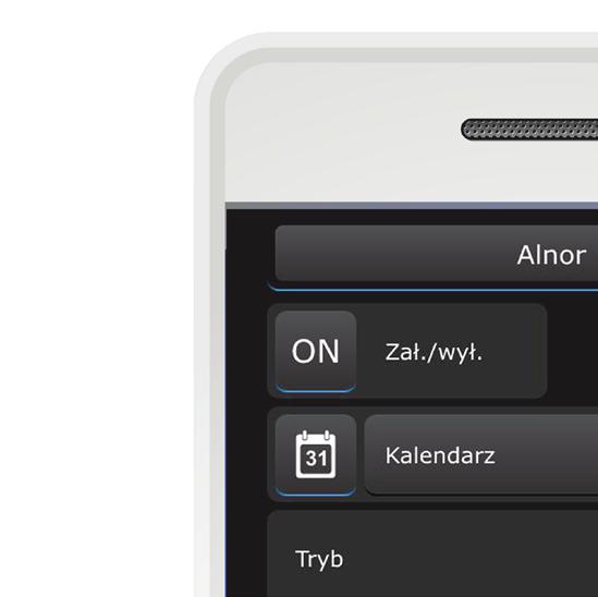
17 Interface - remote control of the heat recovery unit Selection of the interface language version: PL / EN Calendar: functions described on page 18 of the manual. Switching on and switching off the heat recovery unit: ON / OFF Boost function - fan speed boosting Selection of the heat recovery unit operating modes - adjust the permanent operation of the heat recovery unit to your needs or use the selected options in selected situations. STANDARD MODE - permanent air change. It is provided with the option of fan speed change: SUPPLY AIR FAN AND EXHAUST AIR FAN. EXHAUST MODE - it only adjusts the operation of the exhaust air fan. Selection of speeds 1, 2, 3 or ON/OFF. Remove the contaminated air from rooms efficiently by starting this function, and then return to the air change mode, i.e. switch to the STANDARD mode. 15
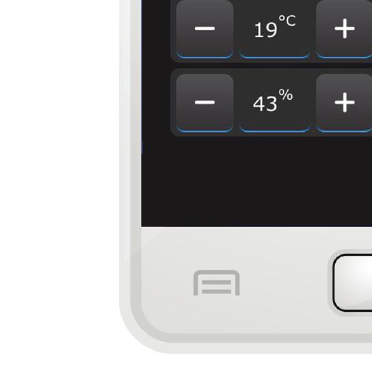
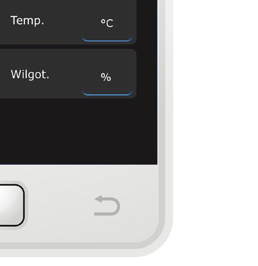
18 Interface - remote control of the heat recovery unit SUPPLY AIR MODE - adjusts the operation of the supply air fan Selection of speeds 1, 2, 3 or ON/OFF. Supply the clean air from outside the building effectively by starting this function, and then return to the air change mode, i.e. switch to the STANDARD mode. VOD mode - in this mode, the air supply and exhaust speed depends on the humidity level on the additional outdoor sensor of the heat recovery unit or depends on the level of concentration of CO2. These sensors are available in the offer separately. While still operating in the VOD mode, we will have one of the two following indications displayed or the humidity level indicator and the possibility of setting its lower and upper range....or the CO2 indicator The display of the type of indicators (humidity or CO2) in the VOD mode in the interface depends on the sensor selected during the configuration of the Wi-Fi network at the stage of setting the connected sensors (see page 9 of the manual). 16

.")


19 Interface - remote control of the heat recovery unit In all the modes - STANDARD, EXHAUST AIR, SUPPLY AIR, VOD - the panel with the following functions, which works as follows is displayed: Connection - shows the proper communication between our By-Pass Function, i.e. supply module and the heat recovery unit of fresh, filtered air indoor, controller. with the omission of the Illuminated marker - correct heat exchanger. connection Illuminated marker - activaalarm code - displays the code that ted by-pass function. identifies the possible error of the heat recovery unit (descriptions of codes are included in the manual). In all the modes - STANDARD, EXHAUST AIR, SUPPLY AIR, VOD - the temperature panel, which functions as follows is displayed: Indoor air temperature - shows the Remotely set temperature temperature of the air removed - you can set the desired from the room and strives temperature in the room. for reaching the remotely set temperature. Temperature of air taken from outside the building. If, during the heat recovery unit setting and Wi-Fi setting configuration we selected the type of the connected heater, in each operating mode of the heat recovery unit - STANDARD, EXHAUST AIR, SUPPLY AIR, VOD - the fields providing information about the type of the heater connected to our heat recovery unit will be displayed - in this case, both heaters are shown. Operating principles for the heaters: 1. Secondary heater: the moment at which the temperature of supplied air is below the temperature set on the temperature panel (in our manual this is 22oC, three screens above), the secondary heater is switched on. At the beginning, it operates with 1/2 of its capacity - i.e. in the first heating level, if it turns out that this capacity is not sufficient, in order to heat the air to the temperature set by us, the second heating level of the heater is switched on. 2. Pre-heater: it is switched on if the temperature of the supplied air falls below the temperature value which was selected by us at the stage of heat recovery unit settings - see the photo in the field: Pre-heater activation temperature [oc]-10. The operation of each of these heaters at a given moment is signalled by illumination of the marker on the left side of their names in the above-mentioned location. After the required parameters of the supplied air temperature are reached, the heaters are automatically switched off and the markers in the interface disappear. GUIDELINE FOR USERS! The heater power should be selected taking into consideration the atmospheric conditions in the given region. NOTE! After connecting the heater to our ventilation system, it is important to switch position 1 and 2 to ON in the electrical box located on top of the heat recovery unit. They are located in a red cube, marked with a white circle in the photograph. Only in this case will they be integrated with our heat recovery unit and read the temperature parameters to which they will adapt their respective operation. 17


20 Interface - remote control of the heat recovery unit CALENDAR In our interface we can set the operation of the heat recovery unit separately for each day of the week. The lit calendar icon [31] informs us about the fact that the operation is defined according to the calendar. Upon entering the calendar settings, first of all we can mark on which days our heat recovery unit will function according to the calendar settings. The illuminated marker means that on this specific day the heat recovery unit operates according to these settings. On a given day of the week we can set when the heat recovery unit is to be switched on/off. At the operation number we need to click the marker so that it is illuminated and this means that this operation will be active and considered in the operation of the heat recovery unit. By clicking and illuminating the ON button, we define the option of switching the heat recovery unit ON. When the ON button is not backlit, we activate the option of switching OFF the heat recovery unit. (the OFF button which is not backlit will be visible) By using the -/+ buttons we set the selected hour and minute in which the heat recovery unit is supposed to be switched on or off (in this example on the screen on the left side, activation is set - this is defined by the backlit ON position in the On/Off field. Another, second operation can be the setting of the OFF option of the heat recovery unit at a specific time. In the On/Off field, we must deactivate the illumination of the button so that only the word OFF is visible. The activation of the OFF function setting takes place after illuminating the marker next to the operation number (in this case next to digit 2). 18 etc.... There is a possibility of setting 6 freely selected operations.


21 Offer Pressed ducts and fittings Valves, grills, anemostats and diffusers FLX REKU home ventilation system Ventilation mounting accessories Insulations for ventilation ducts Flexible ducts Full offer of elements for ventilation: More info at 19
Auxiliary Equipment and Accessories
 http://www.ventilation-alnor.co.uk/index/products_en/heat-recovery-%e2%80%93-air-handling-units/ Description is recommended for use in residential houses with max. area of 200m2. The most important key
HRU-MinistAir-W-450. Elementy dachowe. Heat recovery units. Dimensions. Description. Control. ALNOR systemy wentylacji
 Heat recovery units -W-450 Dimensions 160 710 725 797 Elementy dachowe Description The -W-450 heat recovery unit is designed for single-family houses up to 200 m 2 in usable floor area. 610 630 Key performance
WHAT HAPPENS NEXT FOR ADT SMART BUSINESS CUSTOMERS
 WHAT HAPPENS NEXT FOR ADT SMART BUSINESS CUSTOMERS Below you will find information about your installation and what you can expect to happen next. There are also some important steps to follow to ensure
Heat and energy recovery ventilators
 Description is recommended for use in residential houses with max. area of 200m2. The most important key features of : Heat recovery up to 95% according to EN 308 - TUV SUD Plastic counterflow heat exchanger
Photo 5 Photo 6 Note: Once you connected the dehumidifier to the local network you can install the app on any other mobile phones and use Scan QR key
 1. Your dehumidifier also has the ability to be controlled over WIFI from your smart phone. The first step is to download the correct app. The IOS version is available from Itunes by searching for "IQSmart"
HRU-MinistAir-W-250. Equipment & accessories. Heat recovery units. Dimensions. Description
 Heat recovery units Description www.alnor.com.pl Dimensions Ø 125 600 660 702 Podręcznik użytkownika rekuperatorów is the smallest heat recovery unit in the range of MinistAIR products. With a total air
Safety. Connect the product properly to the ground. (Malfunctioning or power leaks can cause electrical shock.)
") User s Manual TEVHR Contents Safety...1 Control List...2 Components...3 Dimensions...3 Installation...4 Technical Specification...5 Electrical Connection...6 Electrical Scheme...7 Maintenance...10 Control...11
User s Manual TEVHR Contents Safety...1 Control List...2 Components...3 Dimensions...3 Installation...4 Technical Specification...5 Electrical Connection...6 Electrical Scheme...7 Maintenance...10 Control...11
Curv-infrared.com. The Smarter Way. To Heat Your Home. Installation & Operating Instructions For Cürv, Flat, Towel Rail and Mirror Infrared Heaters
 Curv-infrared.com The Smarter Way To Heat Your Home Installation & Operating Instructions For Cürv, Flat, Towel Rail and Mirror Infrared Heaters Safety Precautions Important Notice To Purchaser Before
Water Hero P-100. P-100 Components:
 Water Hero P-100 Thank you for purchasing the Water Hero P-100. The P-100 offers wholebuilding leak detection, mitigation, and water usage monitoring. P-100 Components: Main Controller Water Meter, Sensor
INTELLIGENT AXIAL FAN user's manual
 ACCEPTANCE CERTIFICATE The fan is duly recognized as serviceable. ifan Approval mark Manufactured on (date) Sold (name and stamp of the trade company) INTELLIGENT AXIAL FAN user's manual model VENTS ifan
PX-iP Operating Manual Gateway
 PX-iP Operating Manual Gateway The original version of this instruction has been prepared in German in accordance with DIN EN 82079-1. Content EN 1 Notes on the operating manual 3 2 Safety instructions
WHAT HAPPENS NEXT for ADT Interactive Security Customers
 WHAT HAPPENS NEXT for ADT Interactive Security Customers Interactive Security Below you will find information about your installation and what you can expect to happen next. There are also some important
PX-iP Operating Manual Gateway
 PX-iP Operating Manual Gateway The original version of this instruction has been prepared in German in accordance with DIN EN 82079-1. Table of Contents EN 1 Notes on the operating manual 3 2 Safety instructions
Axial intelligent fan USER S MANUAL
 Axial intelligent fan USER S MANUAL CONTENTS Delivery set... 6 Technical data... 6 Installation and set-up... 9 Connection to power mains... 11 Operation guidelines... 11 Unit control... 12 Storage and
WARNING VL-220CZGV-E. 1. Safety Precautions LOSSNAY HEAT RECOVERY VENTILATOR (RESIDENTIAL USE) Contents. Eng-1. English
 Contents. Eng-1. English") English LOSSNAY HEAT RECOVERY VENTILATOR (RESIDENTIAL USE) MODEL VL-220CZGV-E Instruction Manual For user Contents 1. Safety Precautions 1-2 2. Features 2 3. Preparations Before Use 3 4. Names and Functions
English LOSSNAY HEAT RECOVERY VENTILATOR (RESIDENTIAL USE) MODEL VL-220CZGV-E Instruction Manual For user Contents 1. Safety Precautions 1-2 2. Features 2 3. Preparations Before Use 3 4. Names and Functions
Installer manual AG-WL10
 LEK LED CLEAN TIMER OPERATION Installer manual Indoor unit air/air heat pump IHB GB 1637-1 331827 Table of Contents 1 Important information Safety information Read before starting the installation Electrical
TTV 1500 / TTV 3000 OPERATING MANUAL CONVEYING FAN TRT-BA-TTV TC EN
 TTV 1500 / TTV 3000 EN OPERATING MANUAL CONVEYING FAN TRT-BA-TTV1500-3000-TC2016-26-004-EN Table of contents Notes regarding the operating manual... 2 You can download the current version of the operating
Salusfin Smart heating control: Installation Guide
 Salusfin Smart heating control: Installation Guide Detailed instruction can be found on our web site on all installation phases: FAQ s, Technical user guides and manufacturer s manuals. Video links can
EVAPORATIVE COOLER W
 EVAPORATIVE COOLER 972-1003-W USER MANUAL INTRODUCTION READ AND SAVE THESE INSTRUTIONS! 1 Thanks for your support and choice of our unique tower fan, in order to help you use the product more conveniently,
D3D Wi-Fi GSM Smart Alarm System -User Manual
 D3D Wi-Fi GSM Smart Alarm System -User Manual D3D Wi-Fi / GSM Smart Alarm system (Model : D10). Please read all instructions carefully & follow steps for easy home installation. 1 P a g e D3D Wi-Fi / GSM
INSTALLATION OPERATION & MAINTENANCE INSTRUCTION HEAT RECOVERY UNITS VHR MODELS
 INSTALLATION OPERATION & MAINTENANCE INSTRUCTION HEAT RECOVERY UNITS VHR MODELS TSEK VENCO Havalandırma ve Makina San.ve Tic. A.Ş. 2004. Cad. No:5 45400 OSB Turgutlu MANISA / TURKİYE Tel: +90 (236) 332
Lyric T6 & T6R Smart Thermostat
 Lyric T6 & T6R Smart Thermostat EN User Guide Lyric T6 Programmable Thermostat Lyric T6R Wireless Programmable Thermostat Lyric T6 & T6R Smart Thermostat Features Connects to the Internet so you can control
INSTALLATION OPERATION & MAINTENANCE INSTRUCTION HEAT RECOVERY UNITS VHR MODELS
 INSTALLATION OPERATION & MAINTENANCE INSTRUCTION HEAT RECOVERY UNITS VHR MODELS TSEK VENCO Havalandırma ve Makina San.ve Tic. A.Ş. 2004. Cad. No:5 45400 OSB Turgutlu MANISA / TURKİYE Tel: +90 (236) 332
TIH 300 S / TIH 400 S / TIH 500 S / TIH 700 S / TIH 900 S / TIH 1100 S
 TIH 300 S / TIH 400 S / TIH 500 S / TIH 700 S / TIH 900 S / TIH 1100 S EN OPERATING MANUAL INFRARED HEATING PANEL TRT-BA-TIH300S-TIH400S-TIH500S-TIH700S-TIH900S-TIH1100S-TC-002-EN Table of contents Notes
VERSO DOMEKT. Residential ventilation units m³/h. Non residential ventilation units m³/h
 VENTILATION equipment VENTILATION equipment content DOMEKT Residential ventilation units 50 1 000 m³/h 15 VERSO Non residential ventilation units 1000 34 000 m³/h 61 Domekt R 17 Domekt R 200 V 19 Domekt
Guardian II Pipeline Washer B Instruction Supplement
 Guardian II Pipeline Washer B Instruction Supplement P.O. Box 8050 Madison, WI 53708 608-222-3484 Contents Introduction... 2 1. New Features... 2 1.1 Password For Setup... 2 1.2 Delay... 2 1.3 Date & Time
Silencer Preheater unit Electric post-heating unit Water circulated post-heating unit CO 2 sensor %RH sensor Pressure difference switch LON converter
 VALLOX Product Code: 3158400 L 3158410 R SILENCER (OPTIONAL) INSTRUCTIONS FOR USE AND MAINTENANCE WATER CIRCULATED POST-HEATING UNIT (OPTIONAL) ELECTRIC POST-HEATING UNIT (OPTIONAL)) PREHEATER (OPTIONAL)
User manual AG-WT10. Indoor unit air/air heat pump UHB GB
 User manual Indoor unit air/air heat pump UHB GB 1516-1 331557 Table of Contents 1 Important information Installation data Safety information Serial number an excellent choice Safety instructions Recovery
WATER HEATER ELECTRONIC CONTROLLER USER MANUAL
 WATER HEATER ELECTRONIC CONTROLLER USER MANUAL UPPER LED READOUT LED ICONS LOWER LED READOUT PVI INDUSTRIES, LLC - Fort Worth, Texas 76111 - Web www.pvi.com - Phone 1-800-433-5654 Page 1 / 7 PV500-40 03/17
Smart Smart IR. Service instruction SALES DATE MANUFACTURED ON (DATE): APPROVAL MARK SOLD. model (check applicable) is recognized as serviceable
: APPROVAL MARK SOLD. model (check applicable) is recognized as serviceable") Smart Smart IR model (check applicable) is recognized as serviceable Service instruction SALES DATE MANUFACTURED ON (DATE): SOLD APPROVAL MARK SMART-EN-04 BLAUBERG Company is happy to offer your attention
Smart Smart IR model (check applicable) is recognized as serviceable Service instruction SALES DATE MANUFACTURED ON (DATE): SOLD APPROVAL MARK SMART-EN-04 BLAUBERG Company is happy to offer your attention
1 measurement signal input 4-20 ma for connection to an external gas sensor 5 freely programmable alarm switching points per measuring point
 Medium - Control - System Franke & Haqenest GmbH Borngasse 1a * 04600 Altenburg Tel: 03447-499 313-0 Fax: 03447-499 313-6 email: info@mcs-gaswarnanlagen.de MCS User Guide MCS GasController Microprocessor
Local air conditioner
 Instruction Manual Local air conditioner LAC08C16 Contents Safety Warnings...4 Unpacking...7 Product Overview...8 Front View...8 Rear View...8 Control Panel...9 Remote Control... 10 Moving the Unit...10
Operating Manual PU-27 Control Panel
 EN Operating Manual PU-27 Control Panel Ver. 1.0.0.1. Contents 1 Introduction 3 2 Warranty and liability 3 3 Safety 5 4 Purpose 5 5 Control panel description 5 6 Starting control panel operation 6 7 Main
Alarm module for leak detection with webserver
 This instruction document consists of 2 parts : one part about the assembly of the components and one part about configuration and starting-up of the system. The assembly is done by the qualified installer
WiFi + PSTN. Smart Home Alarm System
 WiFi + PSTN Smart Home Alarm System Content Preface Specifications Technical information Front side panel view Back side panel view Initialization APP names Add alarm host and connect WiFi for host How
3gb53231b.fm5 Page 12 Friday, April 11, :21 PM
 3gb53231b.fm5 Page 12 Friday, April 11, 2003 12:21 PM INSTRUCTIONS FOR USE BEFORE USING THE COOKTOP SUGGESTIONS FOR ENVIRONMENT PROTECTION PRECAUTIONS AND GENERAL ADVICE ENERGY SAVING TIPS CARE AND MAINTENANCE
User Manual 561_U. WiFi Thermostat 561. Introduction 10/16
 User Manual 561_U 10/16 Introduction Zoning Replaces: New The provides precise temperature control of a one-stage heating system. When connected to the Internet, the mobile app and website allows you to
Peak Partners Web-Programmable Thermostat Homeowner s Manual. Look inside for a complete guide to the setup and operation of your new thermostat.
 Peak Partners Web-Programmable Thermostat Homeowner s Manual Look inside for a complete guide to the setup and operation of your new thermostat. Table of Contents Step 1: Getting Started...4-6 A. Thermostat
Renovent Excellent 180 (Plus)
") Renovent Excellent 180 (Plus) INSTALLATION INSTRUCTIONS (English) WWW.BRINKAIRFORLIFE.NL 614293-D Installation instructions Heat recovery appliance Renovent Excellent 180 (Plus) STORE NEAR THE APPLIANCE
Renovent Excellent 180 (Plus) INSTALLATION INSTRUCTIONS (English) WWW.BRINKAIRFORLIFE.NL 614293-D Installation instructions Heat recovery appliance Renovent Excellent 180 (Plus) STORE NEAR THE APPLIANCE
INSTRUCTION MANUAL KETTLE
 INSTRUCTION MANUAL KETTLE PT EL EL SV PT ES NL DE FR EN EN IT Dear Customer, Thank you for purchasing a Smeg 50 s Style kettle. By choosing one of our products, you have selected an appliance which combines
Operating and installation instructions
 Operating and installation instructions Plate warming drawer EGW 3060-10 To avoid the risk of accidents or en-gb damage to the appliance it is essential to read these instructions before it is installed
CHESNEY S. Bio-Ethanol Installation & User Manual. model: EFB1200. Issue 01
 CHESNEY S Bio-Ethanol Installation & User Manual model: EFB1200 Issue 01 1 2 Thank you for choosing this Chesney s Bio-Ethanol fire. Please read this information guide carefully in order to safely install,
TDS 20 R / TDS 30 R / TDS 50 R
 TDS 20 R / TDS 30 R / TDS 50 R EN OPERATING MANUAL ELECTRICAL FAN HEATER TRT-BA-TDS20R-30R-50R-TC-001-EN Table of contents Notes regarding the operating manual... 1 Safety... 1 Information about the device...
TopVent Design Handbook
 TopVent Design Handbook Recirculation Units and Supply Air Units for Heating and Cooling High Spaces TopVent Content TopVent DHV Recirculation unit for heating high spaces TopVent NHV Recirculation unit
IT801 Thermostat. User s Manual. The complete guide to the set up and operation of your new smart Wi-Fi thermostat.
 IT801 Thermostat User s Manual The complete guide to the set up and operation of your new smart Wi-Fi thermostat. The smart Wi-Fi thermostat system learns your comfort preferences, then finds opportunities
USER'S MANUAL PU SENS 01 (A11) PU SENS 01 (A19) Sensor Control Panel
 PU SENS 01 (A19) Sensor Control Panel") USER'S MANUAL PU SENS 01 (A11) PU SENS 01 (A19) Sensor Control Panel PU SENS 01 CONTENTS Safety requirements... 3 Purpose... 4 Technical data... 4 Overall dimensions [mm]... 4 Mounting and set-up... 5
USER'S MANUAL PU SENS 01 (A11) PU SENS 01 (A19) Sensor Control Panel PU SENS 01 CONTENTS Safety requirements... 3 Purpose... 4 Technical data... 4 Overall dimensions [mm]... 4 Mounting and set-up... 5
Register the Gateway via PC. Package Content. Gateway Installation. 1 x Gateway 1 x Voice Siren 1 x IP Camera*
 Package Content 1 x Gateway 1 x Voice Siren 1 x IP Camera* Register the Gateway via PC Create a new account at www.elro-smartalarm.com 1. Click on Create a new account 1 x PIR Motion 1 x Magnetic 1 x Remote
AIRGOCLEAN 10 E OPERATING MANUAL AIR CLEANER TRT-BA-AIRGOCLEAN10E-TC-001-EN
 AIRGOCLEAN 10 E EN OPERATING MANUAL AIR CLEANER TRT-BA-AIRGOCLEAN10E-TC-001-EN Table of contents Notes regarding the operating manual... 1 You can download the current version of the operating manual and
TCH 2000 E OPERATING MANUAL DESIGNER GLASS CONVECTOR TRT-BA-TCH2000E-TC-001-EN
 TCH 2000 E EN OPERATING MANUAL DESIGNER GLASS CONVECTOR TRT-BA-TCH2000E-TC-001-EN Table of contents Notes regarding the operating manual... 1 Safety... 2 Information about the device... 4 Follow the manual
Content. Ⅰ General information 1. Ⅱ Product description 2. Ⅲ System description 3. Ⅳ Fault message 9. Packing list 9
 Content Ⅰ General information 1 Ⅱ Product description 2 Ⅲ System description 3 Ⅳ Fault message 9 Ⅴ Packing list 9 Appendix: Network Connection Manual 1 About this manual This manual book describes the
User manual AG-WT10. Indoor unit air/air heat pump UHB GB LEK
 LEK User manual Indoor unit air/air heat pump UHB GB 1715-3 331557 Table of Contents 1 Important information Installation data Safety information Serial number an excellent choice Safety instructions
ComfortNet CTK04 Featuring the RedLINK Suite of Home Comfort Solutions
 ComfortNet CTK04 Featuring the RedLINK Suite of Home Comfort Solutions Agenda Comfort Advantage System Configurations Installing ComfortNet ComfortNet Control Set up Dehumidification and Defrost Settings
MAXI CENTRALIZED VENTILATION WITH HEAT RECOVERY
 MAXI CENTRALIZED VENTILATION WITH HEAT RECOVERY Product Overview www.orcaenergy.eu MAXI Device for heat recovery MAXI is designed to provide permanent controlled air exchange by means of mechanical ventilation
CHESNEY S. Bio-Ethanol Installation & User Manual. model: EFB1200 with resevoir. Issue 01
 CHESNEY S Bio-Ethanol Installation & User Manual model: EFB1200 with resevoir Issue 01 1 2 Thank you for choosing this Chesney s Bio-Ethanol fire. Please read this information guide carefully in order
Refrigerated Incubator Model and Operating Instructions
 Refrigerated Incubator Model 165000 and 165000-2 Operating Instructions N2400379 - Rev. 1 08May2018 1 Contents 1. SAFETY...3 1.1. EMF INTERFERENCE...4 1. PRODUCT INFORMATION...5 1.1 INTRODUCTION...5 2.
Daikin ENVi Thermostat installation overview
 Daikin ENVi Thermostat installation overview RESIDENTIAL LIGHT COMMERCIAL COMMERCIAL Presenter s Name Presenter s Title Daikin ENVi system overview (web based thermostat) Slide 2 Daikin ENVi System Overview
BarAid 400. Installation and. Starting from Serial No.:
 Glasswasher BarAid 400 Installation and operation Instructions Starting from Serial No.: 8649 1065 REV. 19.01.2009 DE 1618-A-01-09 Content Page 1 Important Notes... 4 2 Installation... 5 2.1 Location...
Renovent Sky 300 (Plus)
") Renovent Sky 300 (Plus) INSTALLATION INSTRUCTIONS (English) WWW.BRINKAIRFORLIFE.NL 612378-E Renovent Sky 300 (Plus) STORE NEAR THE APPLIANCE This appliance can be used by children aged from 8 years and
Renovent Sky 300 (Plus) INSTALLATION INSTRUCTIONS (English) WWW.BRINKAIRFORLIFE.NL 612378-E Renovent Sky 300 (Plus) STORE NEAR THE APPLIANCE This appliance can be used by children aged from 8 years and
Master devices. Type X-AIR-ZMAS. Zone master module for up to 25 zone modules, with integral webserver and interfaces to higher-level systems
 X X testregistrierung Type Web server, also for mobile devices Zone modules Zone master module for up to 25 zone modules, with integral webserver and interfaces to higher-level systems X-AIRCONTROL zone
Honeywell Total Connect Remote Services
 Honeywell Total Connect Remote Services Basic User Guide With Honeywell Total Connect Remote Services, you can stay connected and in control of your home or business whenever you want, wherever you are.
WHE 2.24 / WHE 2.24 FF
 EN Wall-hung gas boilers WHE 2.24 WHE 2.24 FF User Guide 300011777-001-C . Contents 1 Introduction.............................................................................3 1.1 Symbols used...........................................................................................3
APP Function Introduction
 APP Function Introduction IOS/Android Bluetooth 4.1 INMOTION TECHNOLOGIES CO., LTD April, 2015 1 / 29 Content Content... 2 1. General Information... 4 1.1. About this manual... 4 1.2. Related Conventions...
Silhouette Installation and Wiring Instructions
 Silhouette Installation and Wiring Instructions Stock Ref. N 45 40 55B (100B) 44 51 61 (125B) 45 40 59B (150X) 45 40 56B (100T) 44 51 62 (125T) 45 40 60B (150XT) 45 40 57B (100HT) 44 51 63 (125HT) 45 40
Ewpe Smart. Wi-Fi management software
 Ewpe Smart Wi-Fi management software Thanks for chosing AC from Cooper&Hunter Managing your comfort has never been easier, thanks to the highly advanced WIFI control capabilities built into your C&H system.
CENTRIFUGAL FANS user's manual. model VENTS VK.
 EN CENTRIFUGAL FANS user's manual model VENTS VK www.ventilation-system.com 2013 EN! WARNING! Disconnect the fan from power mains prior to any connection, servicing and repair operations. Mounting and
Sensor Control Panel
 USER S MANUAL PU SENS 01 Sensor Control Panel V55-6EN-03(SENS).indd 1 18.08.2015 10:37:16 2 PU SENS 01 CONTENTS Safety Requirements 2 Main Technical Data 3 Control Panel Mounting 3 Control Panel Operation
IMPORTANT SAFETY INFORMATION
 319252GB.fm Page 11 Wednesday, September 3, 28 4:5 PM IMPORTANT SAFETY INFORMATION This manual contains important information regarding safety, the use and maintenance of your new hob. Read the manual
INTRODUCTION... VI I. IOS... 1
 Contents INTRODUCTION... VI PURPOSE... VI KEY FUNCTIONS OF THE SYSTEM... VI TERMS AND ABBREVIATIONS... VII SMART HEATER APPLICATION:... X ios:... x Android:... x Windows:... x PRIVACY POLICY... XI ADAX
INTRODUCTION... VI I. IOS... 1
 Contents INTRODUCTION... VI PURPOSE... VI KEY FUNCTIONS OF THE SYSTEM... VI TERMS AND ABBREVIATIONS... VII SMART HEATER APPLICATION:... X ios:... x Android:... x Windows:... x PRIVACY POLICY... XI ADAX
INSTALLATION INSTRUCTIONS USER GUIDE
 INSTALLATION INSTRUCTIONS USER GUIDE Tilted wall cooker hood HT90GHB2 model GB IE CONTENTS Introduction 3 Safety and warnings 4 Installation instructions 8 About your cooker hood Energy efficiency 18
Swegon CASA R120. Ventilation unit with rotary heat exchanger HOME VENTILATION
 Swegon CASA R120 Ventilation unit with rotary heat exchanger Ventilation unit for residential houses, multi-storey buidings and holiday cottages under 230 m 2. The unit is equipped with rotary heat exchanger.
MODEL: BV400 Part No:
 MODEL: BV400 Part No: 90000312 Mechanical Ventilation with Heat Recovery Installation and Commissioning Manual PLEASE RETAIN THESE INSTRUCTIONS WITH THE PRODUCT INDEX 1. Introduction... 3 2. General Instructions...
INSTALLATION AND OPERATION MANUAL
 INSTALLATION AND OPERATION MANUAL Water Hero P-100 Thank you for purchasing the Water Hero P-100, which offers whole-building leak detection and water conservation monitoring. This box contains: Main Controller
LIFESTYLE R A NGE W A L L M O U N T E D N EW STYLISH, SLIM AN D ELEGANT 5 YEAR F U LL P A R TS & LABOUR W A RRANTY
 LIFESTYLE R A NGE W A L L M O U N T E D N EW STYLISH, SLIM AN D ELEGANT H I GH ENER GY EFFIC IEN C Y 5 YEAR F U LL P A R TS & LABOUR W A RRANTY WHY CHOOSE FUJITSU? AUSTRALIA S FAVOURITE AIR Fujitsu General
SAFETY, INSTALLATION AND MAINTENANCE INSTRUCTIONS
 AQUARIUM LED SAFETY, INSTALLATION AND MAINTENANCE INSTRUCTIONS FULL ONLINE INSTRUCTIONS: www.arcadia.systems READ AND FOLLOW ALL SAFETY INSTRUCTIONS KEEP THESE INSTRUCTIONS FOR FUTURE REFERENCE DANGER-
Healthy Climate Whole-Home Dehumidifier. Nominal Capacity - 70 to 130 pints per day INDOOR AIR QUALITY HCWHD PRODUCT SPECIFICATIONS.
 PRODUCT SPECIFICATIONS INDOOR AIR QUALITY HCWHD Healthy Climate Whole-Home Dehumidifier Bulletin No. 210699 November 2017 Supersedes April 2017 MODEL NUMBER IDENTIFICATION Nominal Capacity - 70 to 130
Connect Your Home Appliance to the Future.
 Connect Your Home Appliance to the Future. Quick-start Guide en-us_plc_wascher_p_ul_control_bo_9001293507.indd 1 21.06.17 06:40 The future begins now in your home! We are glad you have chosen Home Connect
PRODUCT DATA COMFORT 300 TOP BY NILAN. Ventilation & passive heat recovery. Passive heat recovery. < 325 m 3 /h
 PRODUCT DATA COMFORT 300 TOP BY NILAN Ventilation & passive heat recovery Domestic Passive heat recovery Ventilation < 325 m 3 /h COMFORT 300 TOP Product description The Comfort 300 Top is an energy-efficient
DEIF A/S. Description of options. Option M17, Configurable inputs and RPM supervision Engine Controller EC-1/EC-1M. Description of option
 Description of options Option M17, Configurable inputs and RPM supervision Engine Controller EC-1/EC-1M 4189340401D SW 1.4X.X Description of option Functional description DEIF A/S Parameter list DEIF A/S,
PRODUCT DATA COMFORT 450 BY NILAN. Ventilation & passive heat recovery. Passive heat recovery. < 450 m 3 /h
 PRODUCT DATA COMFORT 450 BY NILAN Ventilation & passive heat recovery Domestic Passive heat recovery Ventilation < 450 m 3 /h COMFORT 450 Product description The Comfort 450 is an energy-efficient ventilation
Air handling unit. BlauAir RH USER S MANUAL
 Air handling unit EN USER S MANUAL CONTENTS Safety requirements... 2 Purpose... 4 Delivery set... 4 Designation key... 4 Technical data... 5 Unit design and operation logic... 7 Installation and set-up...
ELECTRIC BOILERS FOR CENTRAL HEATING
 ELECTRIC BOILERS FOR CENTRAL HEATING TermoMax INSTRUCTIONS FOR INSTALLATION INSTRUCTIONS FOR INSTALLATION We reserve the right of alternations WE ARE NOT LIABLE FOR DAMAGES RESULTING FROM NON- OBSERVING
Fire O&M AiM. Need help: call IMS https://sscaimapp.assetworks.com/fmax
 Fire O&M AiM 2016 Need help: call IMS 862-3388 https://sscaimapp.assetworks.com/fmax Fire O&M - 2 Table of Contents What is Fire O&M?... 5 What Appears in Fire App?... 5 Fire O&M Settings... 6 Fire O&M
User and maintenance manual
 GB User and maintenance manual IMPORTANT SAFETY INSTRUCTIONS These instructions shall also be available on website: docs.whirlpool.eu. YOUR SAFETY AND THAT OF OTHERS IS HIGHLY IMPORTANT. This manual and
MyNice Welcome to your Nice World. The intelligent solution for the integrated management of the alarm system and of the home s automations.
 MyNice Welcome to your Nice World The intelligent solution for the integrated management of the alarm system and of the home s automations. Home page Wi-Fi and GSM status and connected users System name
INLINE MIXED FLOW FANS IN SOUND INSULATED CASING VENTS TT SILENT M USER MANUAL
 IIE MIED FOW FAS I SOUD ISUATED CASIG VETS TT SIET M USER MAUA www.ventilation-system.com 2013 ! WARIG Disconnect the fan from power mains prior to any connection, servicing and repair operations. Mounting
USER S MANUAL NKP. Duct heater for supply air pre-heating with external control
 USER S MANUAL Duct heater for supply air pre-heating with external control CONTENTS Contents... 2 Safety requirements... 2 Purpose... 4 Delivery set... 4 Designation key... 4 Technical data... 5 Design
Read this owner's manual thoroughly before operating the appliance and retain it for future reference. TYPE : PORTABLE AIR CONDITIONER
 ENGLISH ESPAÑOL Read this owner's manual thoroughly before operating the appliance and retain it for future reference. TYPE : PORTABLE AIR CONDITIONER MODEL : LP0817WSR LP1017WSR LP1217GSR LP1417SHR LP1417GSR
Schluter -DITRA-HEAT-E-WiFi Thermostat - Troubleshooting Guide External Use and for Inclusion in User Manual and/or Website
 Schluter -DITRA-HEAT-E-WiFi Thermostat - Troubleshooting Guide External Use and for Inclusion in User Manual and/or Website General/Operational Troubleshooting Guide I have an Error Code: E0 (Thermostat
CONTROLS WI-FI THERMOSTAT. icomfort Wi-Fi Flex Thermostat PRODUCT SPECIFICATIONS
 CONTROLS WI-FI THERMOSTAT PRODUCT SPECIFICATIONS icomfort Wi-Fi Flex Thermostat Bulletin No. 210725 December 2015 The icomfort Wi-Fi Flex Thermostat recognizes and connects conventional heating/cooling
USER MANUAL myvacbot SN500 Robot Vacuum
 USER MANUAL myvacbot SN500 Robot Vacuum CONTTS 01 SAFETY INSTRUCTIONS... 6 02 PARTS... 9 03 PRODUCT OVERVIEW... 10 04 CHARGING STATION... 11 05 PRODUCT INSTALLATION... 12 06 PRODUCT CLEANING MODE... 12
Instructions for use
 Instructions for use These instructions are also available on the website: www.kitchenaid.eu Important instructions for safety 4 Installation 6 Safeguarding the environment 6 Troubleshooting guide 7 After-sales
INSTALLATION INSTRUCTIONS and BASIC SYSTEM CONFIGURATION
 INSTALLATION INSTRUCTIONS and BASIC SYSTEM CONFIGURATION 200091-A 2/23 Contents 1. Warnings & Notes... 3 2. Installation of system to electrical cabinet or modular box... 3 3. Powering the system... 7
User manual UV Flash Dry C1
 HENSEL-VISIT GmbH & Co. KG 1 HENSEL-VISIT GmbH & Co. KG Robert-Bunsen-Str. 3 D-97076 Würzburg GERMANY Tel. +49 (0) 931 27881-0 Fax: +49 (0) 931 27881-50 Email: info@hensel.de Internet: http://www.hensel.de
E-Combi One E-System ONE
 discover more @ariston.com G.C.N.: 47-116-83 (24 kw) G.C.N.: 47-116-84 (30 kw) G.C.N.: 41-116-47 (24 kw) G.C.N.: 41-116-48 (30 kw) E-Combi One E-System ONE USER S MANUAL CONDENSING WALL-HUNG GAS BOILER
PCXSPH1732A. Warning. Head office: Umeda Center Bldg., , Nakazaki-Nishi, Kita-ku, Osaka, Japan.
 Warning Daikin products are manufactured for export to numerous countries throughout the world. Prior to purchase, please confirm with your local authorised importer, distributor and/or retailer whether
GB-DAS. Installation and user manual DEVIreg 850 controller
 GB-DAS Installation and user manual DEVIreg 850 controller 1 Table of Contents 1: User Manual System overview......................................... 3 General use..............................................
Control-R Wi-Fi Module
 ENGLISH Control-R Wi-Fi Module Installation Manual For Your Records If you have support questions, please call Customer Care and have your Control-R Wi-Fi module s AYLA ID and Water Heater Serial Number
Warranty Registration
 WARRANT Y AND LIMITS OF LIABILIT Y Vulcain Inc. warrants to the original purchaser that its product and the component parts thereof will be free from defects in workmanship and materials for a period of
Secure Your Way of Life. ESGW EasySmart Gateway Series. A Smart Way of Living Green and Saving Smart
 Secure Your Way of Life ESGW EasySmart Gateway Series A Smart Way of Living Green and Saving Smart ESGW EasySmart Gateway Series A Life-Transforming ZigBee/Z-Wave Innovation The ESGW features optional