Mobile single-shaft shredder TERMINATOR
|
|
|
- Nigel Neal
- 6 years ago
- Views:
Transcription

1 Mobile single-shaft shredder TERMINATOR Model : Type : TERMINATOR 3400D / 3400SD / 5000D/ 5000SD / 6000D Serial number : Year of construction : 2014 Copyright 2011 KOMPTECH Umwelttechnik GmbH. All rights reserved. Printed: 03/2011 Translation of the original instructions: ID Betriebsanleitung_Bedienungsanleitung_Terminator_Diesel_4T_V2_en_PI4485_2_ doc
2 Contents Safety regulations (separate handbook) 1. Safety and dangers Technical specifications (separate handbook) 2. Preface 3. Product identification Operating manual 4. Setting up, commissioning, transport Check the machine upon delivery Delivery status Scope of supply Setting up the machine Unloading / uncoupling Ambient conditions for operation Preparations for operation Personnel training Dangers during commissioning Safety zones Operation Daily preparatory work Commissioning the machine Warm-up phases Control elements of the rear control panel Bring the machine into operating position Transport instructions Preparations for transport Bring the machine into transport position Operation Main control panel Operating elements of the main control panel Relocation Hook with hauling device (optional) Page 2 of 54 Betriebsanleitung_Bedienungsanleitung_Terminator_Diesel_4T_V2_en_PI4485_2_ doc
3 Hook with feed device (optional) Trailer with feed device (optional) Operating elements of mobile versions Wireless remote control Controls of the wireless remote control Operating elements of the wireless remote control for mobile versions Track (optional) Hook with hauling device (optional) Hook with feed device (optional) Trailer with feed device (optional) Service interval reminder Optimization of the shredding mode Optimizing the drum speed and the engine speed Optimizing operating procedures Selection of the shredding program Cycle times for program Switching off the machine Stopping the machine in cases of emergency Index Maintenance instructions (separate handbook) 6. Maintenance 7. Maintenance instructions 8. Faults, causes and remedies 9. Dismantling/disposal Betriebsanleitung_Bedienungsanleitung_Terminator_Diesel_4T_V2_en_PI4485_2_ doc Page 3 of 54
4 4. Setting up, commissioning, transport This chapter describes the preparations required before and during transport, transferring the machine upon delivery, correct setting up as well as instructions for the commissioning of the machine itself Check the machine upon delivery Delivery status Check the machine as soon as it has been delivered to ensure the full scope of supply has been delivered and to verify possible transport damage: The product documentation will be delivered with the machine. The machine will undergo a final inspection before delivery and is fully functional Scope of supply The speciation of the machine you purchased may differ from the functional units and components described in the operating manual. Please take note of your sales contract in this respect. Page 4 of 54 Betriebsanleitung_Bedienungsanleitung_Terminator_Diesel_4T_V2_en_PI4485_2_ doc
5 4.2. Setting up the machine Danger of electrocution. Death and very severe injuries may occur. Make sure that no power supply line is in the swivel range of the discharge belt. Overturning and loss of stability of the machine. Death and very severe injuries may occur. Make sure that the high position of the center of gravity is taken into account for the setup of the machine. The machine dimensions are provided in the model photographs in the handbook "Technical specifications". Observe the local safety and accident prevention regulations when setting up the machine. Make sure that there is enough space available to set up and operate the machine. Betriebsanleitung_Bedienungsanleitung_Terminator_Diesel_4T_V2_en_PI4485_2_ doc Page 5 of 54
6 Select a horizontal and solid surface to set up the machine. If the ground is slightly sloped, take appropriate measures to ensure that the machine is stable. Take appropriate measures to prevent the machine from sinking into soft ground. Make sure that all control panels are and remain easily accessible. Please remember not to block emergency escape routes! Only authorized persons using the compulsory protective equipment are permitted access to the danger areas. Observe all safety distances to other equipment and make sure that no other objects such as high-voltage power lines, other machines, etc. are within the machine's danger zone Unloading / uncoupling HOOK TRACK TRAILER The machine is equipped with lifting eyes. Use suitable lifting tools (lifting straps or chains) and lift the machine from the lowloading truck by means of a crane. Slowly drive the machine down the loading platform via the ramp by means of the wireless control unit. The machine tilts at the breakpoint between the loading platform and the ramp. Do not navigate while the machine tilts! Maximum ramp incline of 12 ( 20% )! Lock the connection pipes (lighting, brake), lower the supporting leg and uncouple the trailer. Page 6 of 54 Betriebsanleitung_Bedienungsanleitung_Terminator_Diesel_4T_V2_en_PI4485_2_ doc
7 Ambient conditions for operation Global use (mobile, outdoor). Optimum temperature range: from -10 C to +37 C (from 14 F to 99 F) Preparations for operation Personnel training No commissioning before factory-provided initial operation. Users are trained how to operate the machine during transfer. The training course has to include the following elements: Safety briefing Operating elements, machine functions Explanations about the use of the operating manual. Request to use the operating manual. Making, checking and changing basic settings Briefing about initial operation (hot startup) Maintenance instructions Betriebsanleitung_Bedienungsanleitung_Terminator_Diesel_4T_V2_en_PI4485_2_ doc Page 7 of 54

8 Dangers during commissioning Operating manual Danger of burning and scalding. Death and very severe injuries may occur. Make sure that the hydraulic hoses are visually inspected and that the screw connections are checked before commissioning. Danger of electrocution. Death and very severe injuries may occur. Make sure that there is no power supply line in the vicinity of the machine when setting up the machine. Page 8 of 54 Betriebsanleitung_Bedienungsanleitung_Terminator_Diesel_4T_V2_en_PI4485_2_ doc
9 Safety zones Respective safety zones have to be maintained: Intrusion of unauthorized persons in the danger zone. Death and very severe injuries may occur. If unauthorized persons enter the danger zone, the operation has to be stopped immediately and unauthorized persons have to be taken away from the danger zone. 1 Access permitted to trained personnel observing the safety regulations. Unauthorized persons are not permitted to enter this area. 2 A Access to trained personnel only when: the machine is switched off and it is secured from unauthorized switch-on. Work area Betriebsanleitung_Bedienungsanleitung_Terminator_Diesel_4T_V2_en_PI4485_2_ doc Page 9 of 54
10 Operation Operation stands for the application of the machine for the purpose of shredding specified materials (see handbook Technical specifications ). If the machine was preset correctly (drum speed, shredding program, engine speed, etc.), it is not necessary for the operating person to intervene. A change of the material or the occurrence of extraneous materials may require a setting adjustment. The respective functions are available during operation. Measures such as servicing or maintenance are not encompassed by the operation section of the machine and described in the handbook Maintenance Instructions Daily preparatory work Check the stability of the machine. Ensure the required machine condition. (Inspection of the safety equipment, inspection of the functionality of the control elements, etc.) Ensure the general readiness for operation of the engine and the machine. (Refill the fuel, check the coolant level and engine oil level, check the indication instruments.) Check all operating materials (hydraulic oil level, lubricant level of the central lubrication system, lubricating points, oil level in planetary gear sets and transfer boxes) Inspect the machine for damage and carry out required repairs immediately. Check cooling fins of the water cooling systems and the hydraulic oil cooling system for staining and clean these elements if required. Check the fuel pre-filter and drain it if required (in case of water in the inspection glass). Clean the engine compartment or keep it dust-free. Page 10 of 54 Betriebsanleitung_Bedienungsanleitung_Terminator_Diesel_4T_V2_en_PI4485_2_ doc

 to")
 All EMERGENCY-STOP SWITCHES")
 Insert the ignition key into the ignition (55) of the main control")
11 You can find a detailed description of the functions of your machine in the handbook Technical Specifications Commissioning the machine ACTIVATE THE BATTERY MAIN SWITCH Switch on the battery main switch (switch is parallel to the housing, see following image for details) to activate the power supply to the control panel. "switched on" RELEASE THE EMERGENCY-STOP BUTTON (11) All EMERGENCY-STOP SWITCHES must be released before the machine can start. IGNITION ON (55) Insert the ignition key into the ignition (55) of the main control panel and turn it from 0 to 1. Betriebsanleitung_Bedienungsanleitung_Terminator_Diesel_4T_V2_en_PI4485_2_ doc Page 11 of 54
 - (10) Wait for the lamp test. All control displays, (1) to (10), have to light up and go out.")
12 DISPLAY ON (20) The display (20) switches on when the ignition (55) is on. The display (20) will initially show the version number of the software. Then the display (20) changes to the main screen. WAIT FOR THE LAMP TEST (1) - (10) Wait for the lamp test. All control displays, (1) to (10), have to light up and go out. (Exception: load control (1) will not go out) START (55) Turn the ignition key to the START position. The machine starts. Take your hand off the key as soon as the engine starts. The key will turn to position 1. The repeat-start lock prevents the ignition from being restarted. First return the ignition key to 0 (ignition off) and repeat the aforementioned procedure to start the engine again. Page 12 of 54 Betriebsanleitung_Bedienungsanleitung_Terminator_Diesel_4T_V2_en_PI4485_2_ doc
13 Warm-up phases Non-compliance with the warm-up phase. A machine breakdown may occur. Comply with the warm-up phases of the respective ambient temperature, particularly with regard to low temperatures! Warm-up stage depending on the ambient temperature Engine oil types SAE 0W40 Engine oil types SAE 5W40-25 C -13 F -20 C -4 F -15 C 5 F -10 C 14 C 0 C 32 F 10 C 50 F 20 C 68 F 30 C 86 F 40 C 104 F You must warm up the machine before beginning work: begin with the lowest engine speed switch on the shredding unit after 10 minutes (in neutral gear without material) increase the engine speed after another 5 minutes You must warm up the machine before beginning work: begin with the lowest engine speed switch on the shredding unit after 5 minutes (in neutral gear without material) increase the engine speed after another 5 minutes Please inquire if the ambient temperature is outside the ranges mentioned above! Betriebsanleitung_Bedienungsanleitung_Terminator_Diesel_4T_V2_en_PI4485_2_ doc Page 13 of 54

14 Control elements of the rear control panel The rear control panel must be used in order to bring the machine into operating position. It is located in the left rear sheet plate housing next to the discharge belt. You can find the control elements for the rear machine components on the bottom control panel. Close the rear hopper wall and run in the telescope walls. Open the rear hopper wall and extend the telescope walls. Steepen the discharge belt or shut it. Level or shut the discharge belt. Reverse the extraction belt (function is only available during maintenance). Moving forward the two conveyor belts (function is only available during maintenance). Page 14 of 54 Betriebsanleitung_Bedienungsanleitung_Terminator_Diesel_4T_V2_en_PI4485_2_ doc
15 Lower the transferring magnet (optionally) and bring it into operating position. Lift the transferring magnet (optionally) and bring it into operating position Bring the machine into operating position Unlock the transferring magnet (optionally) and slew it aside before you bring the discharge belt into operating position! Slew the transferring magnet back and lock it after opening the discharge belt. The machine has a maximum height of approximately 7.5m (25ft) during the opening process of the discharge belt. Make sure that there is enough space for this process! Betriebsanleitung_Bedienungsanleitung_Terminator_Diesel_4T_V2_en_PI4485_2_ doc Page 15 of 54
 2.")
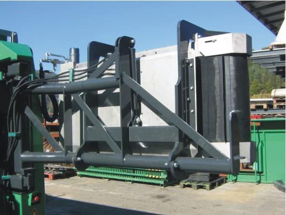
16 1. Transport position with transferring magnet (optional) 2. Swung out transferring magnet Page 16 of 54 Betriebsanleitung_Bedienungsanleitung_Terminator_Diesel_4T_V2_en_PI4485_2_ doc

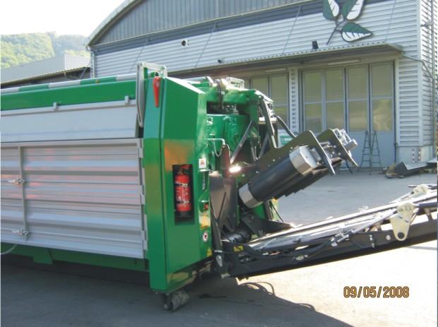
17 3. Fold out the discharge belt 4. Return and lower the transferring magnet Betriebsanleitung_Bedienungsanleitung_Terminator_Diesel_4T_V2_en_PI4485_2_ doc Page 17 of 54
.")

18 5. Fold up the side guiding rail (1) and lock it. Open the two lower conveyor belt doors (2). Illustration without optional transferring magnet Page 18 of 54 Betriebsanleitung_Bedienungsanleitung_Terminator_Diesel_4T_V2_en_PI4485_2_ doc
19 Open the side hopper walls first and then the rear hopper wall! The front hopper wall can be brought into position as required. Press the function buttons (38) and (40) on the main control panel to open the left and right-hand side hopper walls. Press the function button (II) on the rear control panel to open the rear hopper wall and to extend the telescope walls. Press the function button (28) on the main control panel to start the shredding unit and the conveyor belts. Now, the machine is ready for operation and can be applied according to its intended use. Betriebsanleitung_Bedienungsanleitung_Terminator_Diesel_4T_V2_en_PI4485_2_ doc Page 19 of 54
20 4.5. Transport instructions Wrong machine use during transport. Death and very severe injuries may occur. The transport of people and loads on the machine is prohibited! Inappropriate transport preparations. Personal or machine damage may occur. Strictly comply with the following instructions for the transport preparation of the machine! Page 20 of 54 Betriebsanleitung_Bedienungsanleitung_Terminator_Diesel_4T_V2_en_PI4485_2_ doc
21 Preparations for transport Prepare the machine according to its mobile version for transport as follows: UNLOADING / COUPLING Hook Track Trailer The machine is equipped with lifting eyelets (provided that it is not transported by means of a hook lift). Use a suitable hoist (lifting straps or chains) and lift the machine by means of a crane onto the low-loading truck. Slowly drive the machine down the loading platform via the ramp by means of the wireless control unit. The machine tilts at the break-point between the loading platform and the ramp. Do not navigate while the machine tilts! Maximum ramp incline of 12 ( 20% )! Set the tow bar and saddle to the correct height, couple the trailer to the towing vehicle (the coupling has to click into place), connect the lead wires (lighting, brakes) and test everything to make sure that the equipment is functioning properly. Secure the machine (also applies to the hook and the track) to prevent tilting, shifting, etc. according to the respective standards (e.g. EN Load Restraint Equipment on Load Vehicles Safety Part 1: Calculation of Lashing Forces ). Comply with all regulations for the towing of trailers / hooks (maximum speed, permissible axle loads, permissible total weight etc.). Comply with all legal regulations for the transport of heavy goods on public roads and adhere to the general safety regulations. Betriebsanleitung_Bedienungsanleitung_Terminator_Diesel_4T_V2_en_PI4485_2_ doc Page 21 of 54
22 Bring the machine into transport position Bring the machine into the specified transport position before transport. Also see section Bring the machine into transport position. Take the following measures in the following order: 1. Close all doors. 2. Pull in the telescope walls and close the rear hopper wall. 3. Close the left and right-hand hopper walls. 4. Fold and lock the side guiding rails. 5. Slew the transferring magnet (optional) aside and fold the discharge belt. 6. Return and lock the transferring magnet (optional). Page 22 of 54 Betriebsanleitung_Bedienungsanleitung_Terminator_Diesel_4T_V2_en_PI4485_2_ doc

23 5. Operation 5.1. Main control panel The main control panel is located to the front left-hand side of the engine compartment door in a lockable control panel. The main control panel contains all machine control elements, control displays, the display for operating notifications and an EMERGENCY-STOP BUTTON a 52 a 53 a 54 a 53 b 54 b Betriebsanleitung_Bedienungsanleitung_Terminator_Diesel_4T_V2_en_PI4485_2_ doc Page 23 of 54
 The symbol for the charge indicator lights up when the battery is not charging.")
24 5.2. Operating elements of the main control panel If one or several control displays light up, they are also indicated with the respective symbol on the display (20) at the same time. CHARGE INDICATOR (1) The symbol for the charge indicator lights up when the battery is not charging. ENGINE OIL PRESSURE (2) The indicator for the engine oil pressure lights up when the engine oil pressure drops below the threshold value. The engine switches off. COOLANT TEMPERATURE (3) The indicator for the coolant temperature lights up when the coolant temperature is too high. The fan speed and the drum speed are regulated according to the coolant temperature. Controlling the fan speed according to the coolant temperature up to 80 C (176 F) 70% fan speed from 81 C (178 F) 70% fan speed with brief pauses (1.5 s) from 85 C (185 F) Increase in the fan speed by 6% for every 1 C increase from 90 C (194 F) 100% fan speed (in reverse operation always 100%) Controlling the drum speed according to the coolant temperature up to 94 C (201 F) Normal operation of the shredding unit (according to set speed) from 95 C (203 F) Reduction of the drum speed by 10% for every 1 C increase from 99 C (210 F) from 100 C (212 F) from 107 C (225 F) Breakdown of the sensor Drum sped constant at 50% of the maximum value Shredding unit is stopped Engine is stopped Shredding unit is stopped Page 24 of 54 Betriebsanleitung_Bedienungsanleitung_Terminator_Diesel_4T_V2_en_PI4485_2_ doc
25 COOLANT LEVEL (4) The indicator for the coolant level (4) lights up and the symbol shown on the left appears on the display when the coolant level of the engine drops below the threshold value for 10 seconds. The engine switches off. Inspect the machine to establish the reason for the loss of coolant. After establishing the reason for the loss, add sufficient coolant containing 50% antifreeze (also see separate maintenance manual)! AIR FILTER (5) The indicator for the air filter (5) lights up and the symbol shown on the left appears on the display when the air filter is unable to take in sufficient air (e.g. if it is soiled). Clean the air filter! Replace the air filter if the indicator lights up again! HYDRAULIC OIL LEVEL (6) The indicator for the hydraulic oil level (6) lights up and the symbol shown on the left appears on the display when the hydraulic oil level drops below the threshold value. The engine switches off. Inspect the machine to establish the reason for the loss! After establishing the reason for the loss, refill sufficient hydraulic oil! Use the oil level display on the hydraulic oil tank to orient yourself! HYDRAULIC OIL TEMPERATURE (7) The indicator for the hydraulic oil temperature (7) lights up and the symbol shown on the left appears on the display when the hydraulic oil temperature has reached 94 C (201 F). The drum speed is regulated according to the hydraulic oil temperature. Regulation of the drum speed according to the hydraulic oil temperature from 35 C (95 F) up to 90 C (194 F) from 91 C (196 F) from 95 C (203 F) from 96 C (205 F) If a sensor breaks down If several sensors break down Fan is switched on Normal operation of the shredding unit (according to set speed) Reduction of the drum speed by 10% for every 1 C increase Drum sped constant at 50% of the maximum value Shredding unit is stopped Drum speed maximum 50% of the maximum value Shredding unit is stopped Betriebsanleitung_Bedienungsanleitung_Terminator_Diesel_4T_V2_en_PI4485_2_ doc Page 25 of 54
 The indicator for the planetary gear set oil level (8) lights up and the symbol shown on the left appears on the display (20) when the planetary gear set oil level")
26 When the indicator of the hydraulic temperature lights up, the current temperature is shown when you press the information button twice. PLANETARY GEAR SET OIL LEVEL (8) The indicator for the planetary gear set oil level (8) lights up and the symbol shown on the left appears on the display (20) when the planetary gear set oil level drops below the threshold value. The engine switches off. Inspect the machine to establish the reason for the loss! After establishing the reason for the loss, refill sufficient gearbox oil! GEARBOX OIL TEMPERATURE (9) The indicator for the gearbox oil temperature (9) lights up and the symbol shown on the left appears on the display (20) when the gearbox oil temperature has reached 96 C (205 F). The cooling circulation and drum speed are regulated according to the gearbox oil temperature. Regulation of the drum speed according to the gearbox oil temperature from 105 C (221 F) The shredding unit is stopped if the temperature fails to drop after 15 minutes. NOTE (10) The indicator for general maintenance work (10) lights up and the symbol shown on the left appears on the display (20) when the EMERGENCY-STOP BUTTON (11) was pressed. EMERGENCY-STOP BUTTON (11) In an emergency situation or in case a person or the machine may be in danger, press the nearest EMERGENCY-STOP BUTTON (11) to immediately halt the machine and all its components. Clarify the situation and remedy the danger! Then turn the activated EMERGENCY-STOP BUTTON (11) to the left. This unlocks the switch and the switch will pop back out. The machine can now be started again. Page 26 of 54 Betriebsanleitung_Bedienungsanleitung_Terminator_Diesel_4T_V2_en_PI4485_2_ doc

: Increase the drum speed Arrow key (14): Reduce the drum speed SELECTING THE SHREDDING")
 Press the function button (18) to switch to wireless remote control operation.")
 lights up, can you operate the machine via remote control.")
27 DRUM SPEED (12) The current drum speed is indicated via the light-emitting diodes below the symbol for the drum speed (12). The more light-emitting diodes light up, the higher the drum speed. When the machine is switched off, the last drum speed is saved. The next time the machine starts, the drums operate at this speed. Changing the drum speed: Arrow key (13): Increase the drum speed Arrow key (14): Reduce the drum speed SELECTING THE SHREDDING PROGRAM (15) See selection of the shredding program. WIRELESS REMOTE CONTROL (18) Press the function button (18) to switch to wireless remote control operation. The remote control must be switched on before you can do so. Please also refer to the chapter Wireless remote control. When the green LED next to the function button (18) lights up, can you operate the machine via remote control. MAINTENANCE WORK (19) Press the function button (19) to switch to maintenance mode. See separate handbook Maintenance instructions. Betriebsanleitung_Bedienungsanleitung_Terminator_Diesel_4T_V2_en_PI4485_2_ doc Page 27 of 54
. The indicators (1) to (10) light up briefly during the light test.")
 Press the info button (21) to read current values (e.g. hydraulic oil temperature, operating hours of the day) on the display (20). acknowledge operating messages (e.g. fuel capacity MIN ).")
 If the contents of the fuel tank drop below the threshold value, the tank symbol appears on the display and the red light warning light appears.")
28 DISPLAY (20) The display indicates error messages, warnings and operating modes. The display is activated as soon as the ignition is switched on (turn the ignition key to the right, to position 1 ). Current values are showed on the display (e.g. coolant temperature, engine speed, operating hours). The indicators (1) to (10) light up briefly during the light test. The display will briefly show the software version number and the EA-module number. The display will then switch to the main screen. INFO BUTTON (21) Press the info button (21) to read current values (e.g. hydraulic oil temperature, operating hours of the day) on the display (20). acknowledge operating messages (e.g. fuel capacity MIN ). enter and confirm new values (e.g. engine speed adjustment ). TANK CONTENTS (22) If the contents of the fuel tank drop below the threshold value, the tank symbol appears on the display and the red light warning light appears. Refill the machine as soon as possible! The current fuel content is indicated by the light-emitting diodes below the tank symbol (22). The fewer light-emitting diodes light up, the lower the fuel level in the tank. If you are unable to refill the tank immediately, acknowledge the display message via the info button (21). The display message will be displayed again the next time the engine is started. ENGINE SPEED (23) The current engine speed is indicated by the light-emitting diodes under the engine speed symbol (23) and also indicated on the display (20). If the machine is idling, the engine and drum speed are automatically reduced. If material is filled into the hopper, the engine speed increases to the previous speed setting (also see ECO-Mode, button 49). Changing the engine speed: Arrow key (24): Increase the engine speed Arrow key (25): Reduce the engine speed Page 28 of 54 Betriebsanleitung_Bedienungsanleitung_Terminator_Diesel_4T_V2_en_PI4485_2_ doc
 The light-emitting diodes next to the symbol for the shredding unit and conveyor belts (27) indicate whether these are switched on or off.")
 Press the function button (29) to manually reverse the rotation direction of the shredding unit (available as button function in maintenance mode).")
29 STOPPING THE SHREDDING UNIT AND THE CONVEYOR BELTS (26) Press the function button (26) to stop the shredding unit and the conveyor belts. SHREDDING UNIT, CONVEYOR BELTS (27) The light-emitting diodes next to the symbol for the shredding unit and conveyor belts (27) indicate whether these are switched on or off. Red LED: switched off Green LED: switched on STARTING THE SHREDDING UNIT AND THE CONVEYOR BELTS (28) Press the function button (28) in order to start the shredding unit and the conveyor belts. REVERSING THE SHREDDING UNIT (29) Press the function button (29) to manually reverse the rotation direction of the shredding unit (available as button function in maintenance mode). In normal mode, the shredding unit must always be active; switch to forward. MANUAL CONTROL OF THE SHREDDNG UNIT (30) The light-emitting diodes next to the symbol for the shredding unit manual control (30) indicate whether it turns forward or backward. Yellow LED: backward Green LED: forward SHREDDING UNIT, FORWARD (31) Press the function button (31) to manually reverse the rotation direction of the shredding unit to forward (available as button function in maintenance mode). EXTRACTION BELT, REVERSE (32) Press the function button (32) to manually reverse the direction of the extraction belt (only available as button function). The function is used to relieve the machine. Do not use until the shredding process. Betriebsanleitung_Bedienungsanleitung_Terminator_Diesel_4T_V2_en_PI4485_2_ doc Page 29 of 54
30 MANUAL CONVEYOR BELT CONTROL (33) The light-emitting diodes next to the symbol for conveyor belt manual control (33) indicate the direction of the belts. Yellow LED: extraction belt backward, discharge belt forward Green LED: both conveyor belts forward BOTH CONVEYOR BELTS FORWRD (34) Press the function button (34) to manually switch the direction of both conveyor belts to forward (available as button function in maintenance mode). LOWER FRONT HOPPER WALL (35) Decrease the angle of the front hopper wall. LIFT FRONT HOPPER WALL (36) Increase the angle of the front hopper wall. CLOSING THE LEFT HOPPER WALL (37) OPENING THE LEFT HOPPER WALL (38) CLOSING THE RIGHT HOPPER WALL (39) OPERNING THE RIGHT HOPPER WALL (40) Page 30 of 54 Betriebsanleitung_Bedienungsanleitung_Terminator_Diesel_4T_V2_en_PI4485_2_ doc

. Lock counter comb safety device. To prevent inadvertent closing of the counter comb, the counter comb safety device must be locked.")

31 If the ball valve is not switched to the direction of flow (closed), the counter comb remains closed for the shredding mode and can also not be opened in maintenance mode! If the ball valve is switched to the direction of flow (open), the counter comb can be opened or closed by means of the function button (41 or 42). Lock counter comb safety device. To prevent inadvertent closing of the counter comb, the counter comb safety device must be locked. Press the red locking lever (A) to the right and then downward (see images). Counter comb not locked Counter comb locked Danger of crushing due to inadvertent closing of the counter comb. Severe injuries may occur. Lock the counter comb safety device as soon as the counter comb has opened completely. Betriebsanleitung_Bedienungsanleitung_Terminator_Diesel_4T_V2_en_PI4485_2_ doc Page 31 of 54
32 REDUCING THE CUTTING SIZE (41) INCREASE THE CUTTING SIZE (42) PREPARING THE RELOCATION (47) See relocation. COMPLETING THE RELOCATION (48) See relocation. ECO MODE (49) When ECO mode is active, the engine speed automatically drops when the load is reduced to save fuel. We recommend leaving the ECO mode active! In the case of materials which are easy to crush or materials which incur small motor load fluctuations only, the ECO mode should be deactivated. MOISTENING EQUIPMENT (50) (OPTIONAL) Press the function button (50) to moistening the material during the shredding process. Page 32 of 54 Betriebsanleitung_Bedienungsanleitung_Terminator_Diesel_4T_V2_en_PI4485_2_ doc
 When towing the machine with a towing vehicle, the towing angle of 70 (maximum of 85 for a brief period only) must not be exceeded as this will result in increased")
33 5.3. Relocation Hook with hauling device (optional) When towing the machine with a towing vehicle, the towing angle of 70 (maximum of 85 for a brief period only) must not be exceeded as this will result in increased wear on the tires and tow bar. PREPARING THE RELOCATION (47) Press the function button (47) or the function button on the remote control to extend the two reels. COMPLETING THE RELOCATION (48) Press the function button (48) or the function button on the remote control to retract the two reels. Betriebsanleitung_Bedienungsanleitung_Terminator_Diesel_4T_V2_en_PI4485_2_ doc Page 33 of 54
34 Hook with feed device (optional) Operating manual Danger of crushing due to running-in tow wheels. Death and very severe injuries may occur. Keep a sufficient distance to the machine when the tow wheels are extended. Using the optional feed device, you can move the hook forward or backward without a tow vehicle. PREPARING THE RELOCATION (47) Press the function button (47) or the function button on the remote control to extend the back tow wheels and the front support wheels. When the function button (53 b) is pressed, a signal tone resounds and the machine moves forward as long as the button remains pressed (button mode). When the function button (54 b) is pressed, a signal tone resounds and the machine moves backwards as long as the button remains pressed (button mode). 20 seconds after you release the function button (53 b) Forward drive or the function button (54 b) Reverse drive, a signal tone resounds and the support and tow wheels are automatically retracted. Page 34 of 54 Betriebsanleitung_Bedienungsanleitung_Terminator_Diesel_4T_V2_en_PI4485_2_ doc

35 You can also use the hook with feed device with a towing vehicle to move the hook into the desired operating position. In this case, the hook may not be moved with the feed device shortly before as the tow wheels will only be retracted automatically after 20 seconds! Start the machine before towing! The engine must be running so that the brakes can be released. Comply with the maximum towing speed of 6km/h (3.8mp/h)! Always drive the towing vehicle to the hook! If you move the hook to the towing vehicle with the feed device, the towing wheels of the hook may retract automatically while the machine is being towed! COMPLETING THE RELOCATION (48) Press the function button (48) or the function button on the remote control to retract the back tow wheels and the front support wheels Trailer with feed device (optional) The machine can be moved with the feed device only as long as there is sufficient air in the pressure reservoir of the trailers to air the brake. In case of too high loss of pressure, a drawing vehicle with a suitable compressed air system has to be used to move the machine further or to refill the pressure reservoir. The trailer must be secured by means of a stop-block while the pressure reservoir is refilled. With the optional feed device, you can move the trailer forward and backward without a towing vehicle. Betriebsanleitung_Bedienungsanleitung_Terminator_Diesel_4T_V2_en_PI4485_2_ doc Page 35 of 54
36 PREPARING THE RELOCATION (47) Press the function button (47) or the function button on the remote control to adjust the tow wheels to the wheels of the trailer. The drawing vehicle can now be attached. After removing the stop-block and releasing the brake valve, the feed device can be activated. When the function button (53 b) is pressed, a signal tone resounds and the machine moves forward as long as the button remains pressed (button mode). When the function button (54 b) is pressed, a signal tone resounds and the machine moves backwards as long as the button remains pressed (button mode). After relocation the brake valve must be locked and the trailer must be secured by means of the stop-block. A towing vehicle may be attached afterwards if required. COMPLETING THE RELOCATION (48) Press the function button (48) or the function button on the remote control to retract the towing wheels from the tires Operating elements of mobile versions The following functions are available for the main control panel according to the respective scope of delivery. MOVE THE MACHINE FORWARD (53 b) MOVE THE MACHINE BACKWARD (54 b) Page 36 of 54 Betriebsanleitung_Bedienungsanleitung_Terminator_Diesel_4T_V2_en_PI4485_2_ doc
37 TRACK LEFT FORWARD (51 a) Press the function button (51 a) to move the left-hand crawler forward. The machine moves forward in a right-hand bend. TRACK RIGHT FORWARD (52 a) Press the function button (52 a) to move the right-hand crawler forward. The machine moves forward in a left-hand bend. MOVING THE MACHINE FORWARD (51 a) + (52 a) Press the two function buttons (51 a) + (52 a) at the same time to drive the machine straight on. TRACK LEFT BACKWARD (53 a) Press the function button (53 a) to move the left-hand crawler backward. The machine moves in a right-hand bend. TRACK RIGHT BACKWARD (54 a) Press the function button (54 a) to move the right-hand crawler backward. The machine moves in a left-hand bend. MOVING THE MACHINE BACKWARD (53 a) + (54 a) Press the two function buttons (53 a) + (54 a) at the same time to drive the machine straight on. Betriebsanleitung_Bedienungsanleitung_Terminator_Diesel_4T_V2_en_PI4485_2_ doc Page 37 of 54


38 5.5. Wireless remote control Operating the machine by means of the remote control constitutes an increased safety risk. Death and very severe injuries may occur. Adhere carefully to the safety instructions, and pay special attention that third persons stay a sufficient distance away from the machine! The wireless remote control is located in the engine compartment door, front left, in a lockable control cabinet directly next to the main control panel. You can control the most important machine functions by means of the remote control. Wireless remote control hook / hook with hauling device / hook with feed device / trailer / trailer with feed device Wireless remote control track Page 38 of 54 Betriebsanleitung_Bedienungsanleitung_Terminator_Diesel_4T_V2_en_PI4485_2_ doc

39 5.6. Controls of the wireless remote control The MACHINE STOP BUTTON on the wireless remote control can only be used if the wireless remote control is active and a wireless remote connection has been established. The functions of the wireless remote control are only active within the transmission range. If the transmission range is left, the red light of the machine lights up and the shredding unit and the conveyor belts are switched off, the engine turns to idling mode. As soon as the radio contact is established again, the red light of the machine goes out and the shredding unit can be restarted. The engine only increases to its previous speed after the drum-on button was pressed. If the MACHINE-STOP BUTTON of the wireless remote control is not unlocked, the machine engine switches off during the shifting process. Betriebsanleitung_Bedienungsanleitung_Terminator_Diesel_4T_V2_en_PI4485_2_ doc Page 39 of 54
 to the right to start the machine again. This releases the MACHINE-STOP BUTTON (A), which will jump back into position. The machine can not be started again.")
40 MACHINE-STOP BUTTON (A) ON THE WIRELESS REMOTE CONTROL Press the MACHINE-STOP BUTTON on the wireless remote control (A) to stop the engine. Turn the locked MACHINE-STOP BUTTON (A) to the right to start the machine again. This releases the MACHINE-STOP BUTTON (A), which will jump back into position. The machine can not be started again. SWITCHING ON THE WIRELESS REMOTE CONTROL (R) Press the function button (R) to activate the wireless remote control. DRUM FORWARD (B) Press the function button (B) to switch the rotation direction of the drum to forward (function only available in maintenance mode). SWITCHING ON AND OFF THE SHREDDING UNIT AND THE CONVEYOR BELTS (C) Press the function button (C) to switch on/off the shredding unit and the conveyor belts at the same time. The shredding unit switches off first. The conveyor belts continue to run until the machine is empty and stop after a delay. SHREDDING UNIT BACKWARD(D) Press the function button (D) to switch the rotation direction of the shredding unit to backward (function only available in maintenance mode). EXTEND THE TRAILING ARMS (E) EXTEND THE FORWARD DRIVE WHEELS (E) PRESS ON THE SUPPORTING WHEELS (E) See Wireless remote control for mobile versions. Page 40 of 54 Betriebsanleitung_Bedienungsanleitung_Terminator_Diesel_4T_V2_en_PI4485_2_ doc
41 REVERSING THE SHREDDING UNIT (F) Press the function button (F) to switch the rotation direction of the shredding unit to backward. The shredding unit will turn in reverse as long as the button remains pressed (button mode). RUN IN THE TRAILING ARMS (G) RUN IN THE FORWARD DRIVE WHEELS (G) SWIVEL OUT THE SUPPORTING WHEELS (G) See Wireless remote control for mobile versions. OPENING THE LEFT-HAND HOPPER WALL (H) Press the function button (H) to open the left-hand hopper wall. OPENING THE RIGHT-HAND HOPPER WALL (I) Press the function button (I) to open the right-hand hopper wall. UNFOLDING THE DISCHARGE BELT (J) Press the function button (J) to unfold the discharge belt and to bring it into operating position. Press the function button (J) to decrease the operating angle of the discharge belt. CLOSING THE LEFT-HAND HOPPER WALL (K) Press the function button (K) to close the left-hand hopper wall. Betriebsanleitung_Bedienungsanleitung_Terminator_Diesel_4T_V2_en_PI4485_2_ doc Page 41 of 54
42 CLOSING THE RIGHT-HAND HOPPER WALL (L) Press the function button (L) to close the right-hand hopper wall. FOLDING UP THE DISCHARGE BELT (M) Press the function button (M) to increase the working angle of the discharge belt. Press the function button (M) to fold up the discharge belt and to bring it into transport position. REDUCE THE CUTTING SIZE (N) Press the function button (N) to reduce the cutting size between the drum and the counter comb. MOISTENING EQUIPMENT (O) Press the function button (O) to moistening the material during the shredding process (function only available if your machine has moistening equipment). INCREASE THE CUTTING SIZE (P) Press the function button (P) to reduce cutting size between the drum and the counter comb. Page 42 of 54 Betriebsanleitung_Bedienungsanleitung_Terminator_Diesel_4T_V2_en_PI4485_2_ doc
43 WIRELESS REMOTE CONTROL DISPLAY (Q) You can see the following operating modes on the wireless remote control display: DISPLAY Red, flashing point Rapidly flashing L (standing for LOW). The exterior segments rotate clockwise. No indication on the display OPERATING MODE Ready for operation Battery capacity runs out (capacity for only approx. 15 minutes of remote control operation) During the switching-off after pressing the MACHINE- STOP BUTTON (approx. 2 seconds). The machine was switched off by pressing the MACHINE-STOP BUTTON or the battery is flat. Betriebsanleitung_Bedienungsanleitung_Terminator_Diesel_4T_V2_en_PI4485_2_ doc Page 43 of 54
44 5.7. Operating elements of the wireless remote control for mobile versions Different functions of operating elements for options. Personal or machine damage may occur. Please note that the function buttons of the wireless remote control have different functions for tracks, hooks with hauling devices and hooks with feed devices in operating mode than in maintenance mode Track (optional) LEFT-HAND TRACK FORWARD (B) Press the function button (B) to move the left-hand crawler forward. The machine moves forward in a right-hand bend (function only available in operating mode). RIGHT-HAND TRACK FORWARD (D) Press the function button (D) to move the right-hand crawler forward. The machine moves forward in a left-hand bend (function only available in operating mode). MOVING THE TRACK FORWARD (B) + (D) Press the two function buttons (B) + (D) at the same time to drive the machine forward in a straight line (function only available in operating mode). Page 44 of 54 Betriebsanleitung_Bedienungsanleitung_Terminator_Diesel_4T_V2_en_PI4485_2_ doc
45 LEFT-HAND TRACK BACKWARD (E) Press the function button (E) to move the left-hand crawler backward. The machine reverses in a right-hand bend (function only available in operating mode). RIGHT-HAND TRACK BACKWARD (G) Press the function button (G) to move the right-hand crawler backward. The machine reverses in a left-hand bend (function only available in operating mode). MOVING THE TRACK BACKWARD (E) + (G) Press the two function buttons (E) + (G) at the same time to reverse the machine in a straight line (function only available in operating mode) Hook with hauling device (optional) If your machine has a HOOK with hauling device (optional), the towing wheels may be extended by means of the function button (E) and run in by means of the function button (G) (These functions are only available in operating mode). See also Section Relocation Hook with feed device (optional) If your machine has a HOOK with feed device (optional), you can press the function button (B) on the remote control to move the machine forward and the function button (D) to reverse it. The function button (E) is used to extend the back forward wheels and the front supporting wheel and the function button (G) is used to run in them (These functions are only available in operating mode). See also Section Relocation. Betriebsanleitung_Bedienungsanleitung_Terminator_Diesel_4T_V2_en_PI4485_2_ doc Page 45 of 54
 Operating manual If your machine has a TRAILER with feed device (optional), you can press the function button (B) to move the machine forward and the function")
46 Trailer with feed device (optional) Operating manual If your machine has a TRAILER with feed device (optional), you can press the function button (B) to move the machine forward and the function button (D) to move it backward. The function button (E) is used for the pressing on and the function button (G) is used to swing the tow wheels (These functions are only available in operating mode). See also Section Relocation Service interval reminder You received a Service Log Book with your machine. You are required to perform the maintenance work described in this book (see separate maintenance manual ). 30 operating hours before the next maintenance is due, a first message will appear on the INFO display (20) reminding you to perform the maintenance work. Every time you start the machine within the next 50 operating hours, the message Note! Service interval! will be displayed again until you perform the maintenance work! Service work: Perform the service work according to the instructions contained in the accompanying handbook Maintenance manual and make a note of the work performed in the service log book. Page 46 of 54 Betriebsanleitung_Bedienungsanleitung_Terminator_Diesel_4T_V2_en_PI4485_2_ doc
47 5.9. Optimization of the shredding mode If you change the programs while the shredding unit rotates, the new program will only start after you stop and re-start the shredding unit. You can operate the machine using presetting (drum speed, shredding program, engine speed, activated ECO-mode, etc.). However, you can also directly intervene for optimization and change the settings during drive mode Optimizing the drum speed and the engine speed Arrow key (13): Increase the drum speed (12) Arrow key (14): Reduce the drum speed (12) Betriebsanleitung_Bedienungsanleitung_Terminator_Diesel_4T_V2_en_PI4485_2_ doc Page 47 of 54
48 Arrow key (24): Increase the engine speed (23), e.g. when the machine runs at low revs due to the respective material or the material load slows down the drum speed too strongly. Arrow key (25): Reduce the engine speed (23), e.g. when the machine runs at high revs due to the respective material or an insufficient material load makes the shredding unit run too quickly. Deactivate the ECO-mode (49) if you do not wish automatic reduction of performance due to an insufficient material load Optimizing operating procedures In some operating situations, you can directly influence the operating mode of the machine and avoid failures in this way! Press the function button (29) in case of temporary stiffness or imminent blockage of the shredding unit. The rotating direction of the shredding unit will be switched to reverse. Press the function button (29) in case of temporary stiffness or imminent blockage of the extraction belt. Do not use until the shredding process. The extraction belt will be switched to reverse. Page 48 of 54 Betriebsanleitung_Bedienungsanleitung_Terminator_Diesel_4T_V2_en_PI4485_2_ doc
49 Selection of the shredding program The selection of the suitable shredding program (15) strongly depends on the material you wish to shred. The programs differ in terms of different lengths of cycle times for reserve and forward (drum rotation direction). You can operate the machine with the predefined programs 0 8 or the self-definable program 9. The selected program is indicated by the respective light-emitting diode. Select the desired program by means of the arrow keys (16) and (17). The program is activated when switching off- and on the shredding unit. CYCLE TIMES IN SECONDS Program Drum moves forwards Drum moves backwards Minutes and seconds adjustable Seconds adjustable Betriebsanleitung_Bedienungsanleitung_Terminator_Diesel_4T_V2_en_PI4485_2_ doc Page 49 of 54
50 Cycle times for program 9 Operating manual Press the function button (26) to stop the shredding unit and the conveyor belts. Press the function button (26) and one of the two arrow keys (13) or (14) at the same time to access the setting mode. Press the top arrow key (16) to move the cursor to the right to access the program selection. Press the bottom arrow key (17) to move the cursor to the right to access the program selection. Press the top arrow key (24) to increase the value. Press the bottom arrow key (25) to reduce the value. Press the info button (21) to confirm the selected program and to leave the setting mode of program 9. Page 50 of 54 Betriebsanleitung_Bedienungsanleitung_Terminator_Diesel_4T_V2_en_PI4485_2_ doc
51 5.10. Switching off the machine Conveyor belts or shredder units standing still due to a blockade. Severe injuries may occur as the machine may suddenly start when the blockade is removed. Note that stationary conveyor belts or a stationary shredder unit does not necessarily indicate that the machine is switched off. Wrong switching off of the machine. Machine damage may occur. Only use the ignition key and not the battery main switch to switch off the machine. The machine must be completely empty and the shredding unit must be stopped before the machine may be switched off. An idle run of the engine after the shredding process is necessary to prefent turbo troubles. SWITCHING OFF Turn the ignition key in the ignition lock (55) to 0. The engine is stopped. Remove the ignition key! Betriebsanleitung_Bedienungsanleitung_Terminator_Diesel_4T_V2_en_PI4485_2_ doc Page 51 of 54

 on the top right-hand side of the operating panel, the MACHINE- STOP BUTTON (A) on the wireless remote control as well as 2 further EMERGENCY-STOP BUTTONS")
52 5.11. Stopping the machine in cases of emergency Emergency due to failure of the machine. Death and very severe injuries may occur. Press the nearest EMERGENCY-STOP BUTTON to stop the machine and its components immediately in cases of emergency or threatening personal or machine damage. The MACHINE STOP BUTTON on the wireless remote control can only be used if the wireless remote control is active and a wireless remote connection has been established. You will find one EMERGENCY-STOP BUTTON (11) on the top right-hand side of the operating panel, the MACHINE- STOP BUTTON (A) on the wireless remote control as well as 2 further EMERGENCY-STOP BUTTONS behind the machine on the left-hand or right-hand side next to the discharge belt. Page 52 of 54 Betriebsanleitung_Bedienungsanleitung_Terminator_Diesel_4T_V2_en_PI4485_2_ doc
53 Index Battery main switch Commissioning... 4 Conveyor belts... 29, 30, 41, 42, 51 Counter comb Coupling Danger zone... 9 Dimensions... 5 Display Drum speed... 24, 25, 27, 47 ECO-Mode... 32, 48 Emergency-stop-button... 11, 26, 51, 52 Escape routes... 6 Fan speed Functions Gearbox oil temperatur Hook with feed device Hook with hauling device Hopper... 14, 19, 30, 41 Hydraulic oil temperature Hydraulik oil level Ignition Installation site... 6 Machine stop button Main control panel Maintenance work Motor speed... 28, 48 Operating elements... 23, 24, 39 Optimization shredding mode Optionen... 36, 44 Preparations for operation... 7 Preparatory work Relocation... 32, 33, 45, 46 Repeat-start lock Safety zones... 9 Scope of supply... 4 Screen basket Service interval Setting up... 4 Setting up the machine... 5 Shredding program Start Switching off the machine Techical specifications... 5 Technical Specifications Temperature range... 7 Trailer with feed device Transferring magnet Transmission range Transport... 4 Transport instructions Use conditions... 7 Wireless remote control... 27, 38 Betriebsanleitung_Bedienungsanleitung_Terminator_Diesel_4T_V2_en_PI4485_2_ doc Page 53 of 54
![Komptech Umwelttechnik GmbH Kühau 37 A-8130 Frohnleiten [t] +43 3126 59207-0 [t] +43 3126 59207-7777 [e] info@komptech.](/docs-images/71/65770787/images/54-0.jpg "com Komptech GmbH Kühau 37 A-8130 Frohnleiten [t] +43 3126 505-0 [t] +43 3126 505-505 [e] info@komptech.com")
54 Komptech Umwelttechnik GmbH Kühau 37 A-8130 Frohnleiten [t] [t] [e] Komptech GmbH Kühau 37 A-8130 Frohnleiten [t] [t] [e]
Mobile dual-shaft shredder CRAMBO
 Mobile dual-shaft shredder CRAMBO Model: Type: CRAMBO 3400D / 5000D / 6000D Series number: 169 078 Year of construction: 2011 Copyright 2011 KOMPTECH Umwelttechnik GmbH. All rights reserved. Print: 03/2011
PAT LOAD MOMENT INDICATOR DS 150 / 0038
 PAT LOAD MOMENT INDICATOR DS 150 / 0038 INTERACTIVE OPERATOR S HANDBOOK NOTICE The information in this document is subject to change without notice. PAT makes no warranty of any kind with regard to this
Operating manual. Mobile Stone separator. Machine number : 93033
 Mobile Stone separator Model description: Stone separator Type : Stonefex 3000 E Machine number : 93033 Project number : AU13060 Year of manufacture : 2013 DANGER There is unawareness about the machine,
EDITION WITH AUGMENTED REALITY CONTENT
 LOW-SPEED UNIVERSAL WASTE SHREDDER TERMINATOR 1 EDITION WITH AUGMENTED REALITY CONTENT Download the Komptech LookBeyond! app. Scan marked and numbered projects with the LookBeyond! eye to see additional
EDITION WITH AUGMENTED REALITY CONTENT
 UNIVERSAL SHREDDER FOR GREEN WASTE AND WOOD CRAMBO 1 EDITION WITH AUGMENTED REALITY CONTENT Download the Komptech LookBeyond! app. Scan marked and numbered projects with the LookBeyond! eye to see additional
(Battery) Sweeper Scrubber Operator Manual. North America / International Rev. 20 (8-2015) *330630*
 Sweeper Scrubber Operator Manual. North America / International Rev. 20 (8-2015) *330630*") 8300 (Battery) Sweeper Scrubber Operator Manual The Safe Scrubbing Alternative ES Extended Scrub System TennantTrue Parts IRIS a Tennant Technology North America / International For latest parts manual
8300 (Battery) Sweeper Scrubber Operator Manual The Safe Scrubbing Alternative ES Extended Scrub System TennantTrue Parts IRIS a Tennant Technology North America / International For latest parts manual
OPERATIONAL & MAINTENANCE MANUAL Model 7050P Old Style with Dual Troll Bin
 Security Engineered Machinery Co., Inc OPERATIONAL & MAINTENANCE MANUAL Model 7050P Old Style with Dual Troll Bin POP-0027 Rev. 1 Revised: 01/27/2016 Security Engineered Machinery Co., Inc NATIONWIDE SERVICE
*330639* Sweeper Scrubber English EN Operator Manual Rev. 15 (4-2012)
") 8300 Sweeper Scrubber English EN Operator Manual The Safe Scrubbing Alternative ES Extended Scrub System TennantTrue Parts and Supplies To view, print or download the latest manual, visit: www.tennantco.com/manuals
8300 Sweeper Scrubber English EN Operator Manual The Safe Scrubbing Alternative ES Extended Scrub System TennantTrue Parts and Supplies To view, print or download the latest manual, visit: www.tennantco.com/manuals
Illustration shows item no Z Original operating manual. Operating manual. BlueMobil eco. Item no: Z-3278
 Illustration shows item no Z-3278 Operating manual BlueMobil eco Item no: Z-3278 Original operating manual Important Copyright It is essential that you read this manual thoroughly before the initial operation
BarAid 400. Installation and. Starting from Serial No.:
 Glasswasher BarAid 400 Installation and operation Instructions Starting from Serial No.: 8649 1065 REV. 19.01.2009 DE 1618-A-01-09 Content Page 1 Important Notes... 4 2 Installation... 5 2.1 Location...
Owner's Manual TABLE OF CONTENTS
 40MAQ High Wall Ductless System Sizes 09 to 36 Owner's Manual TABLE OF CONTENTS PAGE A NOTE ABOUT SAFETY... 2 GENERAL... 2 PART NAMES... 3 FUNCTION BUTTONS... 4 DISPLAY PANELS... 5 REMOTE CONTROL... 6
Residential Gas Condensing Boiler Greenstar ZBR16/21/28/35/42-3A... ZWB28/35/42-3A...
 70 80 99-00-O Residential Gas Condensing Boiler ZBR//8/35/4-3A... ZWB8/35/4-3A... 70 80 993 (03/03) CA/US Operating Instructions Contents Contents Key to symbols and safety instructions............................
Track Excavator OPERATOR S MANUAL
 1000183743 2.2 0309 Track Excavator 1404 OPERATOR S MANUAL 1 0 0 0 1 8 3 7 4 3 www.wackerneuson.com 1 1.1 Important operator information Special instructions Abbreviations / symbols Store the Operator
7400D *MM426* Operator Manual. MM426 Rev. 13 ( ) The safe scrubbing alternative. R R
 The safe scrubbing alternative. R R") 7400D Operator Manual The safe scrubbing alternative R R www.tennantco.com MM426 Rev. 13 (12-2005) *MM426* This manual is furnished with each new model. It provides necessary operation and maintenance
7400D Operator Manual The safe scrubbing alternative R R www.tennantco.com MM426 Rev. 13 (12-2005) *MM426* This manual is furnished with each new model. It provides necessary operation and maintenance
Operating instructions for the radio heat detector GS412
 Operating instructions for the radio heat detector GS412 Index 1. Safety instructions... 3 2. Suitable and unsuitable locations... 3 2.1 Radio heat detectors should be installed in the following rooms:...
TFV 900 OPERATING MANUAL RADIAL FAN TRT-BA-TFV900-TC-001-EN
 TFV 900 EN OPERATING MANUAL RADIAL FAN TRT-BA-TFV900-TC-001-EN Table of contents Notes regarding the operating manual... 1 Safety... 2 Information about the device... 3 Transport and storage... 4 Start-up...
Glass and Dishwashers 402/452/502. (original instructions) (incl. Australian /502) Starting from Serial No.:
 (incl. Australian /502) Starting from Serial No.:") Glass and Dishwashers ECOMAX 402/452/502 (incl. Australian 452-90/502) INSTALLATION AND OPERATION INSTRUCTIONS (original instructions) Starting from Serial No.: 8663 4000 REV. 05.10.2015 EN IMPORTANT NOTES
Glass and Dishwashers ECOMAX 402/452/502 (incl. Australian 452-90/502) INSTALLATION AND OPERATION INSTRUCTIONS (original instructions) Starting from Serial No.: 8663 4000 REV. 05.10.2015 EN IMPORTANT NOTES
PUMPKIN SEED HARVESTING TECHNOLOGY 2019
 PUMPKIN SEED HARVESTING TECHNOLOGY 2019 Moty GmbH Piesing 20, AT 4846 Redlham office@moty.at www.moty.at Engineering changes, literal mistakes and prices are subjects to change Your reliable partner for
Illustration shows item no Z Original operating manual. Operating manual. BlueMobil 60. Item no: Z-3285
 Operating manual BlueMobil 60 Item no: Z-3285 Original operating manual Illustration shows item no Z-3285 Important Copyright It is essential that you read this manual thoroughly before the initial operation
Operating, Installation and Service Manual W3400H, CLC 41 Clarus Control
 Operating, Installation and Service Manual W3400H, CLC 41 Clarus Control 438 9202-01 05.26 Washer extractor, drum volume 400 litres 3 Contents Machine operation... 7 General description... 7 Automatic
Service Information. WNes 2956 appliance documentation. Service Information no. 27/2004 LHG/TKD-Fe/June SI
 After Sales Service International Service Information Service Information no. 27/2004 LHG/TKD-Fe/June 2004 WNes 2956 appliance documentation Page 1/26 Contents 2.0. Extract from Operating Instructions
Instructions manual DEHUMID HP50
 Instructions manual DEHUMID HP50 Table of contents 1. Unpacking 3 2. Intended use 3 3. Disposal 3 4. Safety instructions 3 5. Functional principle 4 6. Automatic defrosting system 4 7. Set up and transportation
Focus 4010\ Focus 4010 HT porcelain firing furnace
 INSTRUCTION MANUAL Focus 4010\ Focus 4010 HT porcelain firing furnace Warning You have available one of the most precise dental furnaces equipped with a heating muffle made by the original manufacturer
Glass and Dishwashers. BarAid 500/800. Installation and. Starting from Serial No.:
 Glass and Dishwashers BarAid 500/800 Installation and operation Instructions Starting from Serial No.: 8652 0001 REV. 19.01.2009 1617-A-01-09 Content Page 1 Important Notes... 4 2 Installation... 5 2.1
ir-range 8G /03.15 Changes reserved.
 U s e r m a n u a l ic-range is-range ir-range 8G.52.80.00/03.15 Changes reserved. Contents 1. Introduction...3 2. Safety...5 3. Boiler description...6 4. Display and functions...7 4.1 DHW and Heating
OWNER S MANUAL. High-Wall Fan Coil Unit CONTENTS
 OWNER S MANUAL High-Wall Fan Coil Unit Page GENERAL 2,3 OPERATING MODES 2 REMOTE CONTROL 2 OPERATION 3-9 REMOTE CONTROL OPERATION 3 INDOOR UNIT DISPLAY 5 EMERGENCY OPERATION 5 PRESSING THE ON/OFF BUTTON
MICROGUARD RCI 510 TELESCOPIC BOOM CRANES ORs Full 9.7Klb Ctwt ERECTED 60' TELEJIB 17 o
 MICROGUARD RCI 510 TELESCOPIC BOOM CRANES ORs Full 9.7Klb Ctwt ERECTED 0' TELEJIB 17 o PICK FROM MAIN BOOM 30o AUXHD ON FRONT WINCH OPERATOR'S MANUAL 1 of 35 TABLE OF CONTENTS Introduction Outline of Operation...4
Original user manual. Body Drum. page 1 of 35. Jasopels Fabriksvej 19 Sales: tel Fax: Service: tel.
 Original user manual Body Drum page 1 of 35 1. Declaration of Conformity EU Declaration of Conformity Manufacturer: Jasopels A / S Tel. +45 76 94 35 00 Address: Fabriksvej 19, DK-7441 Boarding Machine:
GMH 285 / GMH 285-BNC
 GMH 285 GMH 285-BNC H69.0.01.6C-02 Operating Manual Pt1000 Precision Thermometer For exchangeable probes, with alarm as of version V1.0 GMH 285 / GMH 285-BNC GMH-GREISINGER GMH-GREISINGER WEEE-Reg.-Nr.
TC-710 RECYCLING BALER
 OPERATING AND MAINTENANCE INSTRUCTIONS TC-710 RECYCLING BALER READ INSTRUCTIONS THOROUGHLY BEFORE OPERATING 3451 S. 40th Street Phoenix, AZ 85040 602.437.5020 800.223.4540 www.tsissg.com info@tsissg.com
Shredder FD 8906CC Cross-Cut
 Shredder FD 8906CC Cross-Cut 1/2017 OPERATOR MANUAL Machine Specs Model: FD 8906CC Motor Power Sheet Capacity Serial #: 7.5KW (10HP) Three-phase, 220V, 50/60 Hz, 50 Amp dedicated line required, CS8365
MicroGuard RCI 514 OPERATORS MANUAL PICK FROM BOOM MODE B
 MicroGuard RCI 514 OPERATORS MANUAL 12,700 1 77.8 36.9 6,100 61.0 Crane Setup FULL OUTRIGGERS PICK FROM BOOM MODE B 360 NO AUX HEAD REAR WINCH GREER COMPANY, 11135 South James, Jenks, OK 74037 Telephone
TECHNICAL INFORMATION Touchtronic Clothes Dryers
 TECHNICAL INFORMATION Touchtronic Clothes Dryers Includes: T1302, T1303, T1322, T1329ci T1403 & T1405 2004 Miele This page intentionally left blank. Table of Contents GENERAL INFORMATION A. Warning and
PS-2/ES Automated pack & tag machine with IndES fastening system
 English Manual PS-2/ES Automated pack & tag machine with IndES fastening system Contents 1. Introduction 2. Important Safety Instructions 3. PS-2/ES 4. Unpacking the machine 5. Setting up the machine 6
EYS SEPARATOR EYS 01 G. USER MANUAL for EYS SCREW-PRESS SEPARATOR MODEL EYS 01 G. User Manual for EYS 01G Screw-Press Separator
 USER MANUAL for EYS SCREW-PRESS SEPARATOR MODEL EYS 01 G User Manual for EYS 01G Screw-Press Separator Table of Contents Page 1. Introduction 2 2. General Safety Instructions 3 3. Installation 5 4. Start-up
DLFEHA. OWNER S MANUAL High Wall Ductless System Sizes 09 to 24 TABLE OF CONTENTS
 DLFEHA OWNER S MANUAL High Wall Ductless System Sizes 09 to 24 TABLE OF CONTENTS PAGE A NOTE ABOUT SAFETY... 2 GENERAL... 2 PART NAMES... 3 INDOOR UNIT DISPLAY INDICATOR... 3 REMOTE CONTROLLER... 3 FUNCTION
ACC RADIO CONTROL SYSTEM. Rev A 12/23/14
 ACC RADIO CONTROL SYSTEM Rev A 12/23/14 1 Advanced Crane Control (ACC) ACC- Advanced Crane Control When performing a lift, the crane boom, weight of the load, angle of the truck, and the angle of the boom
Operating manual (Translation of the original version)
") Operating manual (Translation of the original version) TTD 1300 Stolzenberg GmbH & Co. KG Reinigungsmaschinen - Maschinenbau Hamburger Str. 15-17 49124 Georgsmarienhütte Telefon (0 54 01) 83 53-0 Telefax
Operating manual (Translation of the original version) TTD 1300 Stolzenberg GmbH & Co. KG Reinigungsmaschinen - Maschinenbau Hamburger Str. 15-17 49124 Georgsmarienhütte Telefon (0 54 01) 83 53-0 Telefax
Before using your machine, you must familiarize yourself with all of its components.
 USE AND MAINTENANCE MANUAL FOR THE FOAMTEC 1800 NOTE: As with all electrical equipment, care and attention must be exercised at all times during its use, in addition to ensure that routine and preventative
Tornado Operations & Maintenance Manual
 TORNADO INDUSTRIES 7401 W. LAWRENCE AVENUE CHICAGO, IL 60706 (708) 867-5100 FAX (708) 867-6968 www.tornadovac.com Tornado Operations & Maintenance Manual MODEL NO. 99690 BD 22/14, 99720 BD 26/14 L9722
Speedpocket. Sewing unit for runstitching of rectangular piped pockets. Operating Instructions. Installation Instructions. Service Instructions
 745-34 Speedpocket Sewing unit for runstitching of rectangular piped pockets Operating Instructions Installation Instructions Service Instructions Instructions for programming DAC 1 3 4 Postfach 17 03
Low-voltage motors SIMOTICS GP, SD, DP Safety instructions for SH
 Low-voltage motors SIMOTICS GP, SD, DP Readme You can find the associated operating instructions in the Internet: Low-voltage motors (https://support.industry.siemens.com/cs/ww/en/ps/13309/man) Technical
PR-L2466W- PA. Operating Instructions. High Performance Refrigerator PR-L2466W-PA
 Operating Instructions High Performance Refrigerator PR-L2466W- PA PR-L2466W-PA Please read these instructions carefully before using this product, and save this manual for future use. See page 11 for
Tornado Operations & Maintenance Manual
 TORNADO INDUSTRIES 7401 W. LAWRENCE AVENUE CHICAGO, IL 60706 (708) 867-5100 FAX (708) 867-6968 www.tornadovac.com Tornado Operations & Maintenance Manual MODEL NO. 99760 BD26/30 & 99780 BD33/30 L9718AB
SHR3D IT. Version 1.0 November English user guide
 SHR3D IT Version 1.0 November 2017 English user guide COMPANY INFO 3devo B.V. Zonnebaan 12F 3542 EC Utrecht The Netherlands service@3devo.com www.3devo.com TABLE OF CONTENTS 1. SAFETY INSTRUCTIONS... 4
INDIVIDUAL DRIVE, CHAIN DRIVE AND U- SEAL MECHANISM IN ROLLER HEARTH NORMALISING FURNACE
 INDIVIDUAL DRIVE, CHAIN DRIVE AND U- SEAL MECHANISM IN ROLLER HEARTH NORMALISING FURNACE Akash Kumar Mechanical Engineering Dronacharya College of Engg. Gurgaon, Haryana Abstract:- This project deals with
INSTRUCTIONS FOR USE PORTABLE VACUUM SYSTEM LEI Part # s / , , , IMPORTANT INFORMATION
 INSTRUCTIONS FOR USE PORTABLE VACUUM SYSTEM LEI Part # s / 27-009, 27-010, 27-015, 27-020 IMPORTANT INFORMATION UNATHORIZED CHANGES OR ALTERATIONS TO ANY LINCOLN PORTABLE VACUUM SYSTEM WILL AUTOMATICALLY
Glass and Dishwashers AMX / AUX Series
 Glass and Dishwashers AMX / AUX Series INSTALLATION OPERATION REV. 8.xx 04.07.2005 Installation and Operation Instructions for Models of AMX / AUX Series Content Page 1 Installation... 3 2 Connections...
CONTENTS 1. SPECIFICATIONS SET-UP FOR THE OPERATOR MAINTENANCE... 34
 ENGLISH ii CONTENTS. SPECIFICATIONS... 2. SET-UP.... Installing the motor unit... 2. Installing the control box... 3. Installing the belt... 2 4. Adjusting the pulley cover... 2 5. Installation and adjustment
1 and 2 Fan Vision Series Portable Dryers
 1 and 2 Fan Vision Series Portable Dryers Operator s Manual PNEG-1456 Date: 09-29-09 PNEG-1456 2 PNEG-1456 1 and 2 Fan Vision Series Portable Dryers Table of Contents Contents Chapter 1 Safety... 5 Safety
Hazard and Risk Assessment Guide for Dumpmaster bin-tipping machines
 Hazard and Risk Assessment Guide for Dumpmaster bin-tipping machines This document is intended to assist potential customers to determine the level of guarding required in order to meet their obligations
GREEN LIFT SYSTEM USE MANUAL WITH PERMANENT MAGNETS * EN* SYSTEM TYPE: q GLPM MRL 1:1 q GLPM MRL 2: EN.
 Italiano GLB SELL TECH WORK OWNER USER GREEN LIFT SYSTEM WITH PERMANENT MAGNETS 10991792 EN *10991792EN* SYSTEM TYPE: q GLPM MRL 1:1 q GLPM MRL 2:1 ORIGINAL INSTRUCTIONS Verified by GMV Spa GMV SPA FLUID
Operation and Maintenance Manual
 SEBU8860-02 (en-us) August 2016 Operation and Maintenance Manual Tire Monitoring System ELK 2001-6000 (Machine Control & Guidance Products) SAFETY.CAT.COM Important Safety Information i06558969 Most accidents
5700XPS. *mm402* Operator Manual. MM402 Rev.15
 5700XPS Operator Manual MM402 Rev.15 *mm402* This manual is furnished with each new TENNANT Model 5700XPS. It provides necessary operating and preventive maintenance instructions. Read this manual completely
Residential Gas Condensing Boiler Greenstar combi 100 p / 151 p ZWB28-3A... ZWB42-3A...
 Residential Gas Condensing Boiler Greenstar combi 00 p / 5 p ZWB8-3A... ZWB4-3A... Operating Instructions 708733 (07/04) US/CA Contents Contents Explanation of symbols and safety instructions.......................
INDOOR UNIT/OUTDOOR UNIT
 SPLIT TYPE AIR CONDITIONER INDOOR UNIT/OUTDOOR UNIT MODEL RAS-260GA/RAC-260GA RAS-350GA/RAC-350GA OUTDOOR UNIT INDOOR UNIT RAC-260GA RAS-260GA RAS-350GA RAC-350GA Instruction manual Page 1~24 To obtain
Owner's Manual TABLE OF CONTENTS
 40MB*D Ducted Style Ductless System Sizes 09 to 48 Owner's Manual TABLE OF CONTENTS PAGE A NOTE ABOUT SAFETY... 2 GENERAL... 2 PARTS LIST... 3 DISPLAY PANELS... 4 FUNCTION BUTTONS... 5 REMOTE CONTROL...
User instructions DHP-AT
 User instructions DHP-AT VUGFC202 If these instructions are not followed during installation and service, Danfoss A/S liability according to the applicable warranty is not binding. Danfoss A/S retains
CONDITIONS OF SALE AND WARRANTY
 CONDITIONS OF SALE AND WARRANTY 1. Read carefully this operator's handbook before operating our G300 wire-hooder. 2. M.E.P. guarantees his G300 wire-hooder in case of breakages caused by faulty components
INTELLIGENT SUCTION. Upgrade-AtoB
 is a variable speed suction system, that automatically adapts to the clinic s requirements; lift a suction tip and the unit responds by increasing its speed, hang up the tip and the Turbo Smart slows down.
Portable Oxygen Monitor OX-07. (Type B) <No Gas alarm type> Operating Manual
 <No Gas alarm type> Operating Manual") PT0E-0922 Portable Oxygen Monitor OX-07 (Type B) Operating Manual Request for the Customers Read and understand this operating manual before using this gas monitor. Use it in accordance
PT0E-0922 Portable Oxygen Monitor OX-07 (Type B) Operating Manual Request for the Customers Read and understand this operating manual before using this gas monitor. Use it in accordance
BL Series INSTRUCTIONS
 BL Series Models: EX5204/BL514 EX5204/BL515 EX5214/BL524 EX5214/BL525 EXT5214/BL524 EXT5214/BL525 EX5404/BL614 EX5404/BL615 EX5414/BL624 EX5414/BL625 EXT5214H/BL528 EXT5214H/BL529 Automatic Backlatcher
OWNER S MANUAL. R 410A Ductless Split System Air Conditioner and Heat Pump
 R 410A Ductless Split System Air Conditioner and Heat Pump Models DLC4(A/H) Outdoor Unit, DLF4(A/H) Indoor Unit Sizes 9K, 12K, 18K, 24K, 30K and 36K Please read the operating instructions and safety precautions
Glass and Dishwashers AMX / AUX Series
 Glass and Dishwashers AMX / AUX Series INSTALLATION OPERATION VERSION 24.02.04 Important Notes Use in Accordance with Regulations This machine is exclusively to be used to wash ware such as plates, cups,
Excel Click & Go Lite
 User Manual Excel Click & Go Lite Read instructions before use YOU AND / OR YOUR ATTENDANT MUST READ AND FULLY UNDERSTAND THIS MANUAL BEFORE USE General information You have just purchased a Van Os Medical
INDOOR UNIT/OUTDOOR UNIT
 SPLIT TYPE AIR CONDITIONER INDOOR UNIT/OUTDOOR UNIT ENGLISH MODEL RAS-50YHA/RAC-50YHA OUTDOOR UNIT INDOOR UNIT RAC-50YHA RAS-50YHA Instruction manual Page 1~26 To obtain the best performance and ensure
LOUP II DRILL MONITOR OPERATION MANUAL. SOFTWARE v45
 LOUP II DRILL MONITOR OPERATION MANUAL SOFTWARE v45 Service and Technical Support Contact: Loup Electronics Inc. Address: 2960 N. 38th Street Lincoln, NE 68504 Phone: 877-489-LOUP(5687) 402-464-7131 Fax:
OPERATING & SERVICE PARTS MANUAL HDS-215 COMBINATION SHRINK SYSTEM
 OPERATING & SERVICE PARTS MANUAL HDS-215 COMBINATION SHRINK SYSTEM FOR HOT KNIFE AND IMPULSE MACHINES READ ALL INSTRUCTIONS CAREFULLY BEFORE OPERATING EQUIPMENT TABLE OF CONTENTS Electrical Requirements
Owner s Manual. Model AC375C Refrigerant Recovery, Recycle, and Recharge Unit
 Owner s Manual Model AC375C Refrigerant Recovery, Recycle, and Recharge Unit Model AC375C Recover, Recycle, and Recharge Unit for R-12 or R-134a Refrigerant Voltage: 220 230; 50 60 Hz SAFETY DEFINITIONS:
½ CAUTION ½ DANGER. Getting to know the smoke detector. ARGUS Smoke Detector Single. Accessories. Operating instructions. For your safety A B C D E
 Schneider-Electric 2014EAV56178-0102/15 en Getting to know the smoke detector Scope of supply ARGUS Smoke Detector Single Operating instructions Art. no. MEG5470-2119 Accessories Sealing pin for ARGUS
Operating manual. Wascator FOM71 CLS
 Operating manual Wascator FOM71 CLS Operating manual in original language 438 9200-91/EN 2010.05.03 Register now And be able to join the Wascator FOM 71 CLS web site where you can find: General information
BB TM 508/509 ANTI TWO-BLOCK ALARM SYSTEM HYDRAULIC CRANE INSTALLATION. Greer Company Crane Systems. Greer Company
 BB TM 508/509 ANTI TWO-BLOCK ALARM SYSTEM HYDRAULIC CRANE INSTALLATION GREER COMPANY 1918 East Glenwood Place, Santa Ana, CA 92705 Tel: (714) 259-9702 FAX (714) 259-7626 BB TM 508/509 ANTI TWO-BLOCK ALARM
USER S MANUAL LINCOLN PF Manufactured by: Planika Sp. z o.o. ul. Bydgoska Brzoza Poland
 USER S MANUAL LINCOLN PF-0917-0075-000 Manufactured by: Planika Sp. z o.o. ul. Bydgoska 38 86-061 Brzoza Poland Edition i1266#00 as of 25.04.2017 Serial number greater than P5660 17 IT IS OBLIGATORY TO
ScrubMaster 26C OPERATING & MAINTENANCE
 ScrubMaster 26C INTRODUCTION OPERATING & MAINTENANCE INSTRUCTIONS READ THIS BOOK This operator s book has important information for the use and safe operation of this machine. Read this book carefully
Mobile wind sifter. Machine number : Year of manufacture : 2016
 Mobile wind sifter Model description : HURRIKAN S Machine number : 82038 Year of manufacture : 2016 Copyright 2017 Komptech Umwelttechnik GmbH. All rights reserved. Printed: 01/2017 Original instruction
PAC 2000 E OPERATING MANUAL LOCAL AIR CONDITIONER TRT-BA-PAC2000E-TC EN
 PAC 2000 E OPERATING MANUAL LOCAL AIR CONDITIONER TRT-BA-PAC2000E-TC2018-51-005- Table of contents Notes regarding the operating manual... 2 You can download the current version of the operating manual
Installation and Operating Instructions
 ELECTRICALLY OPERATED FOLDING STAIRS Installation and Operating Instructions Premier Loft Ladders ltd Registered Office: 2 Dawson Drive, Trimley St Mary, Felixstowe, Suffolk. IP11 0YW Registered in England
Control of the system, MLP RO pump station
 Control of the system, MLP RO pump station Operating instructions TI071GB-02 /06.11.09/LJ 1/12 Table of contents Humidification pump Safety equipment Selecting RO type Choice of language Normal indications
HI COD REACTOR and Test Tube Heater 2008 Series
 Instruction Manual HI 839800 COD REACTOR and Test Tube Heater 2008 Series www.hannainst.com This Instrument is in Compliance with the CE Directives 1 Dear Customer, Thank you for choosing a Hanna product.
Operating Manual Bathroom Balance
 KERN & Sohn GmbH Ziegelei 1 D-72336 Balingen email: info@kern-sohn.com Phone: +49-[0]7433-9933-0 Fax: +49-[0]7433-9933-149 Internet: www.kern-sohn.com Operating Manual Bathroom Balance KERN MGB Version
Dynapac Chip Spreader is an accessory that enables the spreading of stone chippings, gravel or other similiar granulates in conjunction with the
 Accessories Manual (E2022) Operation & Maintenance Dynapac Chip spreader CC224HF - CC334HF CC2200 - CC3300 CG2300 Dynapac Chip Spreader is an accessory that enables the spreading of stone chippings, gravel
Crimping machine RC AS Operating instructions
 Crimping machine RC AS 4050.456 Operating instructions Contents Contents About this documentation... 4 General safety notes... 5. Intended use... 5. Material that can be processed and crimping shape...
Protection and Power Management, PPM-3 Display and push-button functions Alarm handling Log list Failure mode and effect analysis
 OPERATOR'S MANUAL, PPM-3 Display and push-button functions Alarm handling Log list Failure mode and effect analysis DEIF A/S Frisenborgvej 33 DK-7800 Skive Tel.: +45 9614 9614 Fax: +45 9614 9615 info@deif.com
SuperKlean Washdown Products
 DURAREEL DR8 & DR8S INSTALLATION AND MAINTENANCE INSTRUCTIONS **DO NOT THROW AWAY AFTER INSTALLATION** **SAVE AND DISPLAY PROMINENTLY WHERE THIS EQUIPMENT IS USED** GENERAL WARNINGS High pressure and hot
SHREDDING SCREENING SEPARATION STATIONARY MACHINES
 SHREDDING SCREENING SEPARATION STATIONARY MACHINES THINK GREEN OUR BUSINESS 1 TECHNOLOGIEN EDITION WITH AUGMENTED REALITY CONTENT Download the Komptech LookBeyond! app. Scan marked and numbered projects
Operation Manual 322 KL
 Operation Manual 322 KL 8/07 von Oertzen GmbH Ferdinand-Harten-Str. 10 22949 Ammersbek Tel. +49 40 604110 Fax +49 40 6041149 www.oertzen-gmbh.de info@oertzen-gmbh.de Table of Content 1. Introduction Page
SPLIT TYPE. Instruction manual
 SPLIT TYPE Instruction manual ENGLISH Instruction manual Page 1~24 To obtain the best performance and ensure years of trouble free use, please read this instruction manual completely. 1 SAFETY PRECAUTION
Operator s Manual for Morse Vertical-Lift Drum Pourers
 Contents Page Receiving Procedures.................... 1 Warranty............................. 1 Safety Information..................... 1-2 Machine Description................... 3-4 Operating Instructions....................
Operations Manual TS400. Test Station for G450/G460 Gas Detector
 TS400 Test Station for G450/G460 Gas Detector Operations Manual 1194 Oak Valley Dr, Ste 20, Ann Arbor MI 48108 USA (800) 959-0329 (734) 769-0573 www.goodforgas.com GfG Products for Increased Safety Congratulations
OPERATING INSTRUCTIONS. Cafitesse
 OPERATING INSTRUCTIONS Cafitesse 2000 75508300 02.2004 Contents CONTENTS Introduction... 4 Safety Instructions... 5 Technical Data... 6 Vending Machine Components... 8 Machine front... 8 Operating panel...
status AW1 WiFi Alarm System Printed in China PA : AW1-UM-EN-V1.0 User Manual 2016 Chuango. All Rights Reserved.
 status 2016 Chuango. All Rights Reserved. Printed in China PA : AW1-UM-EN-V1.0 AW1 WiFi Alarm System User Manual Foreword Contents Congratulations on your purchase of the AW1 Alarm system. Before you commence
Telecab17 Residential Elevator OWNER S MANUAL
 Telecab17 Residential Elevator OWNER S MANUAL (To Be Retained by Owner After Installation by Authorized Savaria Dealer) Part No. 001081 30-m06-2017 2 IMPORTANT Ensure that only an authorized Savaria Dealer
Operating Manual. Series FCU5xxx. Sauna Sauna & Humidity Sauna, Humidity & IR Steam Bath FCU5000 FCU5200 FCU5400 FCU5000-STEAM. VDE in preparation
 Series FCU5xxx Operating Manual Sauna Sauna & Humidity Sauna, Humidity & IR Steam Bath FCU5000 FCU5200 FCU5400 FCU5000-STEAM Doc-ID: B_FCU5xxx_EN Version: V 1.01 VDE in preparation reviewed Technical changes
SILENT compact /
 SILT compact 2934 0000 / 2934 1000 TRANSLATION OF THE ORIGINAL INSTRUCTIONS FOR USE Made in Germany Ideas for dental technology 21-2245 21052015 / A Contents 1. Introduction...3 1.1 Symbols...3 2. Safety...3
User Manual Keep this manual safe for future reference
 YDM 3109 User Manual Keep this manual safe for future reference ISL-1213-00 rev.1 The functions and design of this product can be changed without notice for quality improvement. Chinese manual is from
Translation of the original instructions. Type: MPR 150 / 220
 Lebensmitteltechnik Translation of the original instructions - Tumbler Type: MPR 150 / 220 Rühle GmbH, Beim Signauer Schachen 10, D-79865 Grafenhausen Tel.: +49 7748-523-11, Fax: +49 7748-523-8511 www.original-ruehle.de
APC BC300 Series 40kW 208/450/480V User Guide
 APC BC300 Series 40kW 208/450/480V User Guide Copyright 2002 APC Denmark ApS This manual is subject to change without notice and does not represent a commitment on the part of the vendor Thank You Thank
*MM400* (Electric) ( ) Walk -Behind Scrubber Operator Manual. North America / International. MM400 Rev. 20 ( )
 ( ) Walk -Behind Scrubber Operator Manual. North America / International. MM400 Rev. 20 ( )") 5700 (Electric) (000000-029999) Walk -Behind Scrubber Operator Manual The Safe Scrubbing Alternative R R ES Extended Scrub System North America / International www.tennantco.com MM400 Rev. 20 (09-2006)
5700 (Electric) (000000-029999) Walk -Behind Scrubber Operator Manual The Safe Scrubbing Alternative R R ES Extended Scrub System North America / International www.tennantco.com MM400 Rev. 20 (09-2006)
KF-250 Knife Folding Machine
 KF-250 Knife Folding Machine Serial Number Date Page left blank intentionally 2 Table of Contents INTRODUCTION... 5 PREFACE... 5 SPECIFICATIONS... 5 ELECTRICAL SPECIFICATIONS... 6 SAFETY PROCEDURES...
MANUAL OF BIAS AND RADIAL HONEY EXTRACTORS WITH ECONOMIC CONTROL
 MANUAL OF BIAS AND RADIAL HONEY EXTRACTORS WITH ECONOMIC CONTROL CHAPTER 1 MANUAL HONEY EXTRACTOR The substrate on which stands the centrifuge needs to be dry! 6. At the time of the launch honey extractor