INDEX. A Technical Journal from Caleffi Hydronic Solutions
|
|
|
- Ashlynn McCarthy
- 5 years ago
- Views:
Transcription
1


2 Caleffi North America, Inc South 54 th Street Franklin, WI T: F: A Technical Journal from Caleffi Hydronic Solutions CALEFFI NORTH AMERICA, INC 3883 W. Milwaukee Rd Milwaukee, Wisconsin USA Tel: FAX: idronics@caleffi.com Website: To receive future idronics issues FREE, register online Copyright 2013 Caleffi North America, Inc. Printed: Milwaukee, Wisconsin USA Dear Hydronic and Plumbing Professional, Dear Hydronic Professional, Cooling a living space using chilled water is not new. Visit a high-rise hotel room Welcome in summer, to the and 2 nd edition notice of how idronics it is cooled. Caleffi s Chances semi-annual are that design cool journal air enters for hydronic professionals. from a vent located in the wall or ceiling. Behind the vent is a heat exchanger with The chilled 1 st edition water of flowing idronics into was it. released The water in January absorbs 2007 the and heat distributed from room to air over and 80,000 carries people it back in North to a chiller America. that It extracts focused on the the heat topic and hydraulic rejects separation. it outside From the the building. feedback After received, being it s re-cooled, evident we the attained water returns our goal back of explaining to the room the benefits completing and proper the application cooling cycle. of this modern design technique for hydronic systems. With If you advances haven t in yet technology, received a copy hydronic of idronics cooling #1, is you no can longer do so limited by sending to highrises and other large commercial buildings. Improvements in chilled-water in the attached reader response card, or by registering online at The publication will be mailed to you free of charge. You can also download the generators, complete journal distribution as a PDF equipment file from and our piping Web site. have made hydronic cooling practical for residential and lighter commercial buildings. These systems offer advantages This second over edition traditional addresses forms air of and cooling, dirt hydronic including systems. reduced Though electrical not a new energy topic usage, to our industry, simple zoning, the use thermal of modern storage high-efficiency and less equipment invasive installation. demands a thorough understanding of the harmful effects of air and dirt, as well as knowledge This on issue how to of eliminate idronics them. explores Doing several so helps methods ensure of the hydronic systems cooling you design using will operate at peak efficiency and provide long trouble-free service. currently available products and highlights the benefits and performance advantages We trust you of these will find systems. this issue We of hope idronics you a enjoy useful it, educational and encourage tool and you a handy to send reference us any for feedback your future about hydronic idronics system by ing designs. us We at also idronics@caleffi.com. encourage you to send us feedback on this issue of idronics using the attached reader response card or by For ing prior issues, us at please idronics@caleffi.com. visit us at and click on the icon. There you can download the PDF files. You can also register to receive hard copies of future issues. Sincerely, Mark Olson Mark Olson General Manager, Caleffi North America, Inc. General Manager & CEO INDEX 1. INTRODUCTION 2. A BRIEF HISTORY OF COOLING 3. BENEFITS OF CHILLED-WATER COOLING 4. CHILLED-WATER SOURCES 5. HEAT ABSORBERS FOR HYDRONIC COOLING 6. DESIGN CONSIDERATIONS 7. EXAMPLE SYSTEMS APPENDIX A: Piping symbol legend APPENDIX B: Sizing expansion tanks in chilled-water systems APPENDIX C: Psychometric chart Disclaimer: Caleffi makes no warranty that the information presented in idronics meets the mechanical, electrical or other code requirements applicable within a given jurisdiction. The diagrams presented in idronics are conceptual, and do not represent complete schematics for any specific installation. Local codes may require differences in design, or safety devices relative to those shown in idronics. It is the responsibility of those adapting any information presented in idronics to verify that such adaptations meet or exceed local code requirements. Mixed Sources Products from well-managed forests, controlled sources and recycled wood or fiber.

3 Hydronic Cooling For Residential & Light-commercial Buildings Hydronic heating is a widely recognized technology, one that s respected for delivering superior comfort and energy-efficient operation. However, one commonly perceived limitation of hydronics technology, especially in residential and light-commercial buildings, is the ability to provide cooling. Modern hydronics technology in combination with recent developments in equipment that can efficiently produce chilled water have made it practical to use hydronicbased cooling in smaller buildings. Such systems offer several benefits relative to other methods of cooling. This issue of idronics focuses on the hardware and design details appropriate to hydronic cooling in residential and light-commercial buildings. It explores several methods of hydronic cooling using a wide range of currently available hardware. It also shows how to integrate chilled-water cooling with several methods of modern hydronic heating to provide year-round comfort. The ancient Egyptians learned to improve the comfort of their interior spaces during warm and dry weather by hanging reeds in windows and trickling water down them. The water evaporating from the surface of the reeds absorbed heat from the dry desert air as it passed through. This was likely one of the earliest uses of evaporative cooling. In ancient Rome, water supplied from aqueducts was routed through the walls of buildings to provide cooling. Today, the use of water to cool surfaces that can then absorb heat is called radiant cooling The Persians constructed wind towers, as seen in Figure 2-1. These structures created a column of rising air similar to the draft created by a chimney. The rising air would pull air through the attached building, creating air currents that improved comfort. Figure 2-1 Most people living in developed countries take building cooling for granted. Most expect it in the office buildings or shops where they work. They also expect it in the cars, buses, airplanes and trains that carry them on their daily outings. With exception of some far northern homes or homes at high elevation, most homeowners now expect cooling in their homes. This expectation has become increasingly common over the last 50 years. However, before that, building cooling was the exception rather than the rule. Attempts to limit the temperature of occupied spaces date back to early civilizations living in caves. Even in tropical climates, the temperature of soil not exposed to the sun, as well as shade from direct sunlight, provided some relief from what most of us would now consider unbearably high temperatures and humidity levels. Source: Wikipedia In the mid-1700s, Benjamin Franklin demonstrated that the rapid evaporation of volatile compounds such as alcohol and ether could cause the object from which the evaporation was occurring to drop as much as 7ºF below room temperature. Advances in chemistry during the 19 th century laid the foundation for the first mechanical cooling devices. These machines used ammonia as their refrigerant, alternately compressing and expanding it to transfer heat through a crude version of what is now known as the vapor compression cycle. 3


4 In colder climates, ice was often harvested from ponds and lakes during winter and stored as best as possible, for cooling food during warmer weather. However, the amount of ice needed to cool a home of that vintage was far more than what could be practically managed. Figure 2-2 windows located lower in the room. This arrangement created a weak stack effect within buildings that tended to channel rising warm air within the building and use it to draw outside air in through exterior windows. Operable transom windows can still be seen in many older homes and office buildings. Figure 2-3 shows an example of such a window, with its associated hardware that allows it to be operated from a normal standing height. When electricity became available, motorized fans helped provide relief to the discomfort associated with high air temperatures and high humidity. The increased air velocity across exposed skin encourages evaporation of perspiration, and thus allows better heat dissipation from the body. However, fans cannot reduce interior humidity, and thus were less effective during high humidity conditions. It is also important to know that an electric fan, operating in a closed room, adds heat to the room at a rate equal to the motor wattage. Figure 2-4 Until electricity became available in urban areas during the early 1900s, there was little relief from oppressive summer heat and humidity, especially on still days. Cross ventilation through open windows provided some relief, if there was a breeze to be had. Another technique that induced some air movement was the use of transom windows over interior doors, in combination with opened Figure 2-3a Figure 2-3b transom window warmer air Source: open window cooler air The first use of refrigeration-based cooling for industrial applications dates back to 1902, when Willis Carrier developed an ammonia-based refrigeration system for a Brooklyn printing plant. Cooling for human comfort dates back to 1924, when a centrifugal chiller also designed by Willis Carrier was installed in a Detroit department store. The luxury it provided at the time soon lead to a market for cooling in movie theaters and other public buildings. By 1928, Carrier had created the first residential cooling devices. The continued development of air conditioning played a major role in the development of the southern United States during the 1900s. 4

5 Figure 2-5 Courtesy of Carrier Corporation Before widespread use of refrigeration-based cooling, most buildings equipped with central heating used steam or water to deliver heat from a boiler to radiators in various parts of a building. As devices for cooling were developed and electricity became increasingly available, fans and blowers quickly became the dominant method for delivering cooling comfort. The primary reason was that a forced-air delivery system could deliver heating, cooling and ventilation, while a hydronic system could only provide heating. It was impractical to cool and dehumidify room air by circulating cool water through devices such as radiators due to the condensation of moisture on their surfaces. Operating a radiator in such a manner would quickly lead to puddles on the floor, surface corrosion and mold. The increased demand for cooling in modern American buildings lead to forced air becoming the dominant delivery method for most residential and commercial HVAC systems. This remains evident today, with forced-air HVAC systems being used in over 90% of new American homes. However, the same physical properties that make water well-suited for transporting heat through a building also give it distinct performance advantages in moving heat out of rooms and rejecting it outside the building. This has been recognized and applied in cooling systems for large buildings for several decades. Water, rather than air, has been used as the primary transport media for cooling in these larger systems. In most systems, the chilled water eventually transfers cooling delivery to one or more air handlers located throughout the building, as shown in Figure 2-6. Recent developments in hydronics technology now make it practical to use chilled-water cooling in smaller buildings. Such systems offer several benefits over all air systems. Those benefits are discussed in the next section. Figure 2-6 modulating dampers spray nozzles evaporative cooling tower exhaust air air handler(s) return air outdoor air cool / dry air condenser chiller evaporator 5
6 There are several benefits to chilled-water cooling. They include the following: Minimally in asi e installation Red ced electrical energy sage A ailability o many chillers Easy zoning No coil rosting Adaptability to radiant panel cooling Adaptability to chilled-beam cooling Possibility o se o re ected heat Lower re rigerant ol me Adaptability to thermal storage Each of these benefits will be discussed in further detail within this section and in the remainder of this issue. Minimally in asi e installation: For a given temperature rise, liquid water can absorb almost 3,500 times more heat than the same volume of air. This has profound implications regarding the size of the piping required to convey chilled water through a building versus the size of ducting required to move a thermally equivalent amount of air through that building. 20-inch-wide by 12-inch-deep duct, or an 18-inch-round duct, as shown in Figure 3-1. Either of these ducts would be difficult to conceal within the normal framing cavities of residential and light-commercial buildings. Red ced electrical energy sage: A cooling distribution system operating with chilled water can use significantly less electrical power compared to a forcedair distribution system of equivalent thermal capacity. The difference can best be expressed through a calculation of distribution efficiency, which is defined by Formula 3-1: Formula 3-1 Published data for the blower in a geothermal waterto-air heat pump using forced-air delivery indicates that a 3/4-horsepower motor is required to deliver approximately 1,500 CFM airflow. The estimated electrical input power to this motor when operating at full capacity is 690 watts. The rated total cooling capacity of this unit is about 53,000 Btu/hr (based on 60ºF entering water temperature). The heat pump s distribution efficiency under these conditions is: Figure 3-1 chilled water 3/4" tube = 20" air 12" An equivalent hydronic system is assumed to have 200 feet equivalent length of 1 copper tubing. It will operate with a 15ºF chilled-water temperature rise (45ºF to 60ºF) across the heat absorber(s). It uses a standard wet rotor circulator with a PSC motor operating at an assumed 22% wire-to-water efficiency. The water flow rate required for delivering 53,000 Btu/hr at a 15ºF temperature change is: chilled water 3/4" tube = air 18" Assuming a 200-foot total equivalent length for the circuit, the pressure drop in the circuit is 5.2 psi. The power supplied to the circulator can be estimated using Formula 3-2: Formula 3-2: For example, a 3/4-inch tube carrying chilled water at a flow rate of 6 gallons per minute through a heat absorber unit that absorbs enough heat to warm the water by 15ºF is conveying 45,000 Btu/hr. To do this with a duct operating at a face velocity of 1,000 feet per minute and an air temperature change of 30ºF requires a cross-section of 240 square inches. This translates to a Where: w = electrical input power to circulator (watts) f = flow rate through circulator (gpm) ΔP = pressure increase across circulator (psi) e = wire-to-water efficiency of circulator (decimal %) 6

7 Figure 3-2 zone s chilled water air handlers to / from chiller temperature sensor variable speed pressure regulated circulator balancing s ThermoCon buffer tank For the assumed chilled-water distribution system, the estimated electrical input to the circulator is: The distribution efficiency can now be calculated using Formula 3-1: This comparison shows that the chilled-water delivery system is using only about 10% of the electrical power required by the equivalent forced-air system. There may or may not be a blower within the heat absorber unit through which the chilled water is circulated. If a blower is present, its power input must be added to that of the circulator when calculating distribution efficiency. pumps and gas-fired absorption heat pumps. In some circumstances, it is also possible to use water from a lake to directly cool a building. These options are each discussed in more detail in Section 4. Chilled-water cooling systems are very easy to zone. They can be designed around electrically operated zone s in combination with variable speed pressure-regulated circulators, as shown in Figure 3-2. They can also be designed around individual zone circulators. Designers should always verify the lowest rated operating temperature of circulators to ensure they are compatible with chilled-water distribution systems. Figure 3-3 Keep in mind that all electrical input to a cooling distribution system ultimately becomes a heat gain to the building. Thus, when high energy efficiency is a primary design goal, it is imperative to minimize the electrical input power required to operate the cooling distribution system. Hydronic delivery options will typically provide significantly lower electrical energy usage than a thermally equivalent all air system. A wide variety of devices are now available as small-scale chillers. These include dedicated chillers, such as non-reversible water-towater heat pumps and air-cooled condenser units, as well as reversible heat pumps. The latter category includes water-to-water heat pumps, air-to-water heat Source: 7
 coils.")

8 Circulators that are not compatible with a minimum water temperature of 40ºF should not be used for chilled-water distribution systems. Many air handlers and fan coils used for cooling have direct expansion (e.g., DX ) coils. Liquid refrigerant flows into these coils and evaporates as it absorbs heat from the air stream passing across the coil. In some cases, the temperature of the refrigerant within the coil can be lower than 32ºF. This creates a potential for frost to form on the exterior surfaces of the coil, as seen in Figure 3-3. The frost forms as water vapor in the air freezes to the fins and tubing surfaces of the coil. This effect is worsened if the airflow rate across the coil is lower than the rated airflow. The latter are often the result of improperly sizing ducting that restricts airflow. This phenomena will not occur with chilled-water coils, because the water must be above freezing to flow through the distribution system. This benefit is not mentioned to condone inadequate airflow, but rather to point out the more forgiving nature of a chilled-water versus direct expansion coil. Figure 3-4 doing this are described in later sections. This constraint only allows the radiant ceiling to address the sensible portion of the total cooling load. Other equipment is required to handle the latent portion of the cooling load. Chilled beams are specially designed heat absorption units that use chilled water to generate a gentle cooling airflow within a room using natural convection. Although relatively new to North America, chilled beams have been used in European buildings since the 1970s. Like radiant ceilings, they are only intended to handle the sensible portion of the cooling load. Figure 3-5 shows a typical chilled beam for installation in a suspended ceiling grid. Figure 3-5 Source: activechilledbeam.com Chilled beams are categorized as active and passive. Active chilled beams have ventilation air ducted to them. This air has been preconditioned in both temperature and moisture content before it is sent to the chilled beam. This preconditioning allows the air to absorb the latent portion of the cooling load. It enters the chilled beam and mixes with the airflow induced by natural convection. Passive chilled beams do not have ventilation air ducted to them. Both types of chilled beams are discussed in more detail in Section 5. The distribution energy saved through use of chilled beams has proven to be as much as 50% lower than that required by VAV (Variable Air Volume) systems. Chilled-beam cooling is also known to be very quiet and comfortable. Chilled water can be used for radiant panel cooling. Ceiling surfaces are ideal for absorbing heat from the occupied space below. An example of a radiant ceiling that can provide both heating and radiant cooling is shown in Figure 3-4. The chilled water supplied for radiant panel cooling must always be at a temperature above the current dewpoint temperature of the room. This prevents water vapor in the air from condensing on the radiant panel. Methods for The heat of rejection from a chiller may be of use for simultaneous heating loads within the building. One example is preheating (or fully heating) domestic water using the heat rejected from a water-to-water heat pump supplying chilled water for cooling. Another is using the heat rejected from a chiller to warm a swimming pool. In commercial buildings, it is not uncommon to have situations in which the core areas of the building require cooling, even when the exposed perimeter areas of the building require heating. This is an ideal application for heat pump technology. The setup for such a heat pump is shown in Figure
9 Figure 3-6 to / from other heat pumps chilled buffer tank simultaneous loads heat pump compressor evaporator condenser heated buffer tank 4-pipe distribution system TXV When both the chilled water and heat of rejection are useful, the effective coefficient of performance (COP) of the heat pump is given by Formula 3-3. Formula 3-3: Where: COP e = effective net COP of the heat pump, considering total energy flows COP = coefficient of performance of heat pump as measured or calculated Thus, a heat pump operating with a measured COP of 4.0, in this type of application, would have an effective COP of (2x4)-1 = 7. Such a heat pump is providing a very beneficial effect, relative to the electrical energy it consumes. Figure 3-7 COOLING MODE diverting heating zones air-to-water heat pump OUTSIDE INSIDE 4-port reversing (cooling mode) upper sensor well vent tube antifreeze protected circuit heat exchanger lower sensor well 4-port reversing (cooling mode) Thermal Storage tank 9
10 Chilled-water cooling systems typically contain far less refrigerant than direct expansion (DX) or variable refrigerant flow (VRF) cooling systems. This is important for several reasons. First, a leak in a commercial (VRF) system could mean the loss of many pounds of refrigerant. Not only is this expensive, it is also undesirable from the standpoint of releasing gases that contribute to climate change. Second, the type of refrigerants used in current generation VRF systems may not be the same as those used in the future. There is no guarantee that a currently installed VRF system will be compatible with future refrigerants or oils. Incompatibility could require a major changeout in equipment. However, any future chiller will remain compatible with a hydronicbased distribution system. Third, water-based systems allow for thermal storage, which is not feasible with systems that distribute thermal energy using refrigerant. Finally, water-based systems are adaptable to low power technology such as radiant cooling, chilled beams and direct lake source cooling. Chilled-water cooling is adaptable to thermal storage where preferential time-of-use electrical rates or ambient temperatures make this approach feasible. One example of a system that leverages thermal storage is shown in Figure 3-7. An air-to-water heat pump operates during the most favorable outdoor conditions: typically during the daytime for heating and at night for cooling. The heat pump transfers energy to a large and very well-insulated thermal storage tank. In heating mode, the tank is warmed. In cooling mode, the tank is chilled. Thermal energy is then transferred between this tank and the load as required. Thermal storage also allows for extensive zoning of the distribution system, where necessary, without concern for short cycling the heat pump. A properly configured thermal storage tank can also serve as a hydraulic separator between multiple circulators within the system. In the common situation where the heating load of a building exceeds the cooling load, the presence of some thermal storage also allows the heat pump to be sized for the full design heating load, without concern over short cycling during cooling operation. 10
11 A wide variety of devices are now available for producing chilled water at heat transfer rates suitable for residential and light-commercial buildings. They include: Figure 4-1 medium temperature VAPOR SOURCE media LIQUID Figure 4-2 low temperature heat absorbed from source (Q1) evaporator 1 electrical power input (Q2) evaporator compressor 2 4 thermal expansion (TXV) 3 condenser compressor condenser All heat pumps convert low temperature heat into higher temperature heat. Most of the heat pumps now in use do this using a vapor compression refrigeration cycle. To describe how this cycle works, a quantity of refrigerant will be followed through the complete cycle, as illustrated in Figure 4-1. The cycle begins at station (1) as cold liquid refrigerant within the evaporator. At this point, the refrigerant is colder than the source media (e.g., air or water) passing across the evaporator. Because of this temperature difference, heat moves high temperature high pressure VAPOR LOAD media medium temperature high pressure LIQUID higher temperature heat dissipated to load (Q3) from the higher temperature source media into the lower temperature refrigerant. As the refrigerant absorbs this heat, it changes from a liquid to a vapor (e.g., it evaporates). The vaporized refrigerant continues to absorb heat until it is slightly warmer than the temperature at which it evaporates. The additional heat required to raise the temperature of the refrigerant above its saturation temperature (e.g., where it vaporizes) is called superheat, and it also comes from the source media. This vaporized refrigerant then flows into the compressor at station (2). Here a reciprocating piston or an orbiting scroll, driven by an electric motor, compresses the vaporized refrigerant. This causes a large increase in both pressure and temperature. The electrical energy used to operate the compressor is also converted to heat and added to the refrigerant. The temperature of the refrigerant gas leaving the compressor is usually in the range of 120ºF to 170ºF, depending on the operating conditions. thermal expansion (TXV) Q1 Q2 Q3 The hot refrigerant gas then flows into the condenser at station (3). Here it transfers heat to a stream of water or air (e.g., the load media), which carries the heat away to the load. As it gives up heat, the refrigerant changes from a high-pressure, high-temperature vapor into a high-pressure, somewhat cooler liquid (e.g., it condenses). 11
12 The high-pressure liquid refrigerant then flows through the thermal expansion at station (4), where its pressure is greatly reduced. The drop in pressure causes a corresponding drop in temperature, restoring the refrigerant to the same condition at which this description of the cycle began. The refrigerant is now ready to repeat the cycle. Figure 4-3 low pressure gas slide compressor discharge high pressure refrigerant vapor capilary tubing Figure 4-2 shows the three primary energy flows involved in the refrigeration cycle. The first energy input is low-temperature heat absorbed into the refrigerant at the evaporator. The second energy input is electrical energy flowing into the compressor whenever it is operating. The 3 rd energy flow is the heat output from the condenser. The first law of thermodynamics dictates that the total energy input rate to the heat pump must equal the total energy output rate. Thus, the sum of the low-temperature heat absorption rate into the refrigerant at the evaporator plus the rate of electrical energy input to the compressor must equal the rate of energy dissipation from the refrigerant at the condenser. This is depicted by the arrows in Figure 4-2. In chilled-water cooling systems, the source of the low-temperature heat is the water circulating through the chilled-water distribution system. The water temperature within such a distribution system is typically maintained in the range of 45ºF to 65ºF when the cooling system is operating. This from low temp. HX (a) to high temp. HX (b) water temperature is low enough that heat readily flows into it as it passes through heat exchangers, such as the coil within an air handler or the tubing embedded within a radiant panel. The generic term used for such devices is heat absorber. After the chilled water passes through a heat absorber, it carries the heat it absorbs back to the chiller. The chiller extracts this heat from the water, returning it to a suitable low temperature and readying it for another pass through the distribution system. high pressure refrigerant vapor compressor suction compressor discharge compressor suction slide to high temp. HX capilary tubing low pressure gas from low temp. HX capilary tubing pilot solenoid pilot solenoid the unique benefits of modern heat pumps is that the refrigerant flow can be reversed to immediately convert the heat pump from a heating device to a cooling device. Such heat pumps are said to be reversible. A reversible heat pump that heats a building in cold weather can also cool that building during warm weather. Reversible heat pumps contain an electrically operated device called a reversing, which is illustrated in Figure 4-3. off capilary tubing 24 VAC REVERSIBLE HEAT PUMPS: The non-reversible heat pump shown in Figures 4-1 and 4-2 can be used as either a dedicated heating device or a dedicated cooling device. Although there are several applications for such heat pumps, one of When the reversing is not energized, refrigerant flow is such that the heat pump is in heating mode. When low-voltage power is applied to the reversing, it moves an internal element that changes the direction of refrigerant flow through both the evaporator and condenser. 12

13 Figure 4-4 Figure 4-5 HEATING MODE compressor reversing low temperature heat absorbed evaporator thermal expansion (TXV) condenser higher temperature heat dissipated compressor Courtesy of ClimateMaster. COOLING MODE reversing Figure 4-4 shows the overall refrigeration system with the reversing operating in both heating and cooling modes. higher temperature heat dissipated condenser thermal expansion (TXV) evaporator low temperature heat absorbed The reversing effectively swaps the functions of the two water-to-refrigerant heat exchangers within the heat pump. The heat exchanger that serves as the evaporator in the heating mode serves as the condenser in the cooling mode. Similarly, the other heat exchanger that serves as the condenser in the heating mode acts as the evaporator in the cooling mode. Figure 4-6 "sink" heat rejection circuit cooling mode compressor reversing condenser TXV evaporator ducting warm/moist air chilled water distribution system terminal unit (air handler) condensate (liquid water) ducting cool/drier air 13
14 WATER-TO-WATER HEAT PUMPS: One of the most versatile hydronic heat pumps is known more specifically as a water-to-water heat pump. An example of such a device is shown in Figure 4-5. When a water-to-water heat pump is used for cooling, the slightly warmed water returning from the chilledwater distribution system passes into the heat pump s evaporator. Here, it gives up heat to low-temperature liquid refrigerant, causing it to vaporize. The refrigerant vapor is compressed and passed to the heat pump s condenser. Here, heat is transferred to another stream of fluid that carries the heat away to some sink, such as an earth loop heat exchanger. Figure 4-6 illustrates a very basic chilled-water cooling system using a reversible water-to-water heat pump as the chiller. The thermal performance of any heat pump providing cooling is given by two indices: Cooling capacity represents the total cooling effect (sensible cooling plus latent cooling) that a given heat pump can produce while operating at specific conditions. Heat pumps that deliver cooling through a forced-air distribution system have separate ratings for sensible and latent cooling capacity. However, a water-to-water heat pump has a single total cooling capacity rating. This rating is affected by the temperature of the fluid streams passing through the evaporator and condenser. To a lesser extent, it s also affected by the flow rates of these two fluid streams. The cooling capacity of a typical water-to-water heat pump with a nominal cooling capacity of 3 tons (36,000 Btu/hr) is represented graphically in Figure 4-7. The horizontal axis shows entering source water temperature. This is the temperature of the water returning from the cooling distribution system, and flowing into the heat pump s evaporator. The three sloping curves on the graph represent three entering load water temperatures. These represent the temperature of the fluid stream to which the heat is being dissipated. For example, the blue line showing an ELWT of 50ºF could represent fluid returning from an earth loop and entering the heat pump at 50ºF. As the temperature of the entering source water goes up, so does the heat pump s cooling capacity. Thus, the heat pump yields a higher cooling capacity when supplied with 60ºF water compared to when it is supplied with 50ºF water. The leaving chilled water temperature will typically be 8ºF to 12ºF lower than the entering source water temperature. It can also be seen that increasing the temperature of the fluid into which heat is dissipated (an earth loop for example) lowers the heat pump s cooling capacity. ENERGY EFFICIENCY RATIO: In North America, the common way of expressing the instantaneous cooling efficiency of a heat pump is an index called EER (Energy Efficiency Ratio), which is defined as follows: Figure 4-7 total cooling capacity (Btu/hr) ELWT = 50ºF ELWT = 70ºF ELWT = 90ºF (temperature of water entering heat pump from earth loop) where: EER = Energy Efficiency Ratio Q c = cooling capacity (Btu/hr) W e = electrical input wattage to heat pump (watts) The higher the EER of a heat pump, the lower the electrical power required to produce a given rate of cooling. Like COP, the EER of a water-to-water heat pump is a function of the source and load water temperature. This variation is shown in Figure Entering SOURCE water temperature (ºF) (water returning from distribution system) This graph shows that EER increases as the temperature of the entering source water (e.g., the water temperature returning from the cooling distribution system) increases. However, 14
, the higher the EER.")
15 Figure 4-8 Figure 4-9 EER (Energy E ciency Ratio) Btu/hr/watt Entering SOURCE water temperature (ºF) (water returning from distribution system) higher entering source water temperature reduces the distribution system s ability to cool and dehumidify the building. It can also be seen that the cooler the load water temperature (e.g., the water into which heat is being rejected), the higher the EER. Design decisions that reduce the temperature difference between the entering source water and load water will improve the cooling capacity and EER of the heat pump. Higher fluid flow rates through the evaporator, the condenser or both, will also increase cooling capacity and EER. However, increased flow also require higher electrical power input to the circulator(s) creating this flow. Flow rates above 3 gallons per minute per ton (12,000 Btu/hr) of heat transfer are not necessary or desirable. Figure 4-10 rejected heat ELWT = 50ºF ELWT = 70ºF ELWT = 90ºF (temperature of water entering heat pump from earth loop) air-to-water heat pump Courtesy of Mestek. ducting to bring outside air to the heat pump, which is located inside a building, along with a separate duct to return this air outside. When operating in heating mode, an air-to-water heat pump adds higher temperature heat to a stream of water (or a mixture of water and antifreeze) passing through the heat pump. The stream of water conveys this heat to the remainder of a hydronic distribution system. When operating in cooling mode, an air-to-water heat pump absorbs heat from the stream of water, thus cooling it for use in a chilled-water cooling system. Figure 4-9 shows the outside unit of a modern air-towater heat pump. Figure 4-10 shows how such a heat outside inside ducting warm/moist air air handler ducting cool/drier air Most air-to-water heat pumps designed for HVAC applications use an outside unit as either the source of low-temperature heat (when operating in heating mode) or as the sink into which heat is rejected (when operating in cooling mode). A smaller percentage of airto-water heat pumps use diverter low temperature hydronic heating 15
16 Figure 4-11 rejected heat air-to-water heat pump outside inside ducting warm/moist air air handler ducting cool/drier air antifreeze protected circuit heat exchanger diverter low temperature hydronic heating Figure 4-12 outside inside indoor unit (w/ internal circulator) ducting air handler ducting outdoor unit warm/moist air cool/drier air diverter refrigerant line set Sep 4 low temperature hydronic heating pump would be connected to a hydronic system that provides both chilled-water cooling and heating. The system shown in Figure 4-10 circulates water between the air-to-water heat pump and the interior portions of the system. This is generally acceptable in climates that experience minimal freezing conditions. Most air-to-water heat pumps have internal controls that operate the circulator and possibly energize a small electrical heating element within the heat pump to 16

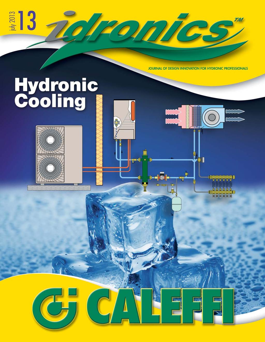
17 prevent freezing. While effective when electrical power is available, this method of freeze protection will not work during prolonged power outages in cold winter climates. Providing freeze protection in these situations requires the use of antifreeze in all components that might be exposed to freezing conditions. In small systems, the entire system is generally filled with a solution of propylene glycol. In large systems, a heat exchanger is installed between the heat pump and the indoor portion of the system, as shown in Figure Other types of air-to-water heat pumps use a split refrigeration system like that of an air-to-air heat pump. A set of refrigerant tubes connects the outdoor unit with the indoor unit, as shown in Figure 4-12 (operating in cooling mode). This type of heat pump eliminates any water in the outdoor unit, and thus eliminates any need for freeze protection. However, split system heat pumps require proper installation and charging of refrigerant line sets, and thus require an installation technician trained and equipped for such work. Some non-reversible air-to-water heat pumps are used for dedicated domestic water heating applications. However, most air-to-water heat pumps intended for HVAC applications are reversible. As such, they are capable of producing chilled water for building cooling. Later sections discuss how to apply air-to-water heat pumps for hydronic cooling applications. The cooling capacity of an air-to-water heat pump is also a strong function of both outdoor air temperature and chilled-water temperature. Figure 4-13 shows the nominal cooling capacity of three air-to-water heat pumps with nominal capacity ratings of 3, 4 and 4.5 tons, respectively. These cooling capacities are based on an Figure 4-13 Designers should be aware that some air-to-water heat pumps are supplied with their own internal circulator and expansion tank. While these components may be adequate for small system applications with minimal zoning, they are not necessarily properly Figure 4-14 sized for all applications. Designers should verify the flow rate and head available from the internal 4.5 ton air-to-water heat pump circulator and compare it to the flow rate and leaving chilled water temp = 59 ºF head required by the distribution system. If leaving chilled water temp = 55 ºF the distribution system requires significantly different flow and head, a separate circulator leaving chilled water temp = 50 ºF should be installed. Figure 4-12 shows how a leaving chilled water temp = 45 ºF hydraulic separator can be installed between nominal rating the indoor unit of the heat pump and the remainder of the distribution system to provide hydraulic separation between the heat pump s internal circulator and the circulator used for the distribution system. The Caleffi SEP 4 hydraulic separator also provides high-performance air and magnetic dirt separation for the system The relatively small expansion tanks supplied with some air-to-water heat pumps are adequate for small system applications, but may not be large enough to accommodate the expansion needs of larger, high-volume systems. If a supplemental expansion tank is required, it should be piped into the system as close to the connection point of the supplied tank as possible. The air pressure in both Oudoor air temperature (ºF) tanks should also be adjusted to the same value. Cooling capacity (Btu/hr) 17
18 outdoor air temperature of 95ºF, a water temperature of 64.4ºF leaving the evaporator and a temperature increase of 9ºF across the cooling distribution system. Figure 4-14 shows how the cooling capacity of the larger heat pump model (4.5-ton) is affected by different outdoor air and chilled-water temperatures. The yellow dot represents nominal cooling capacity rating of 57,070 Btu/hr. To maximize cooling performance, designers should plan the chilled-water distribution system to operate at the highest possible chilled-water temperature that still allows for adequate latent cooling (e.g., moisture removal). Chilled-water supply temperatures in the range of 45ºF to 55ºF will generally provide adequate performance, especially when combined with a deep cooling coil with multiple tube passes. Figure ton air-to-water heat pump leaving chilled water temp = 59 ºF leaving chilled water temp = 55 ºF leaving chilled water temp = 50 ºF leaving chilled water temp = 45 ºF Figure 4-15 shows the Energy Efficiency Ratio (EER) of the same heat pump. The trending of EER mimics that of cooling capacity. Lower outdoor air temperatures and higher chilled-water temperatures improve EER, and thus provide a given cooling effect using less electrical input. These factors can be exploited by operating the heat pump under the most favorable conditions, which for cooling is usually at night. Adding thermal storage can also help leverage these favorable operating conditions. It is also possible to combine a standard outdoor condenser, as would be used for a central (forced-air based) cooling system, with a refrigerant-to-water heat exchanger, as shown in Figure When there is a call for cooling, a controller measures the temperature of the buffer tank. Its objective is to maintain the chilled water within a specific temperature range, such as between 45ºF and 60ºF. When the water in the tank reaches the upper end of this temperature range, the controller turns on the circulator that supplies flow through the refrigerant-to-water heat exchanger. Once flow is established in this circuit, the flow switch contacts close. This enables operation of the condenser unit. The flow switch is necessary to protect the heat exchanger from a potential freeze if water is not flowing through it at some minimum rate. The buffer tank is sized to allow the condenser unit to operate for at least 10 minutes once it is turned on. This tank also provides hydraulic separation between the heat exchanger circulator and the variable speed distribution circulator. The coolest water in the system will accumulate at the bottom of the buffer tank due to its slightly higher density. When one of the zone thermostats calls for cooling, the zone is energized. When it reaches its fully open position, the end switch in the zone closes to signal for circulator operation. The variable speed pressure-regulated circulator turns on and operates in either constant differential pressure or proportional differential pressure mode, depending on the design of the distribution system. Notice that the zone s and circulator are located on the chilled-water return piping. This exposes them to slightly warmer water compared to the supply side of the distribution system, which reduces the potential for condensation. The external stainless steel heat exchanger in this system is specifically designed to operate as a water-torefrigerant evaporator in combination with the air-cooled condenser unit. An example of such a heat exchanger is shown in Figure This heat exchanger must be properly sized based on the refrigerant used, the desired evaporator temperature, the superheat setting of the thermal expansion in the condenser unit, and the required chilled-water temperature and flow rate. Figure 4-18 shows a typical residential-scale aircooled condenser unit. Unlike a heat pump, condenser 18


19 Figure 4-16 Figure 4-17 Figure 4-18 chilled water air handler zone balancing Courtesy of GEA PHE Systems variable speed pressure-regulated circulator NOTE: All piping and components containing chilled water must be insulated and vapor sealed to prevent condensation. switch inside outside rejected heat temperature sensor temperature controller refrigerant piping outside air heat exchanger air-cooled condenser chilled water buffer tank units are non-reversible, and as such, only function as a cooling device. Whenever possible, air-cooled condensers should be mounted in shaded locations that receive good air circulation. They should also be mounted away from windows or other areas where the sound of their operation might be objectionable. Outdoor condensers should also be kept free of debris such as leaves and grass clippings. 19


20 Figure 4-19 to / from cooling distribution system variable speed pressure-regulated circulator switches 2-stage temperature controller temperature sensor heat exchangers DX line sets air-cooled condensers chilled water buffer tank circulators with check s Figure 4-20 Figure 4-21 In larger systems, it is possible to add multiple outdoor condensers and operate them in stages based on the demand for chilled water. Figure 4-19 shows how each condenser unit is piped to a separate heat exchanger. A flow switch should be installed on each branch, as shown in Figure Each flow switch verifies that a suitable flow rate exists through the water side of the refrigerant-to-water evaporator before allowing the condenser unit to operate. Notice that all piping, as well as the lower body of the flow switch, are insulated to minimize condensation formation on components carrying chilled water. 20

21 Although heat pumps using a vapor compression cycle are very common, they are not the only option for producing chilled water for cooling residential and light-commercial buildings. One alternative that has recently become available in North America is a gas-fired absorption heat pump. An example of an air-to-water absorption heat pump is shown in Figure Figure 4-22 These heat pumps operate using an absorption refrigeration cycle. This process uses heat, generated by a gas-fired combustion system, as the primary thermal driving force. The only electricity required is for operating a small internal diaphragm pump and the outdoor air fan motor. The air-to-water versions of gas-fired absorption heat pumps are designed for outdoor mounting. They typically have a short, stainless steel venting stack, as seen in Figure In cold climate applications, they are typically set up to transfer heat to an internal flat plate heat exchanger. An antifreeze solution is used in the circuit between the outdoor unit and interior heat exchanger. When operating in a heating mode, absorption cycle heat pumps are capable of supplying water temperatures up to about 149ºF. In cooling mode operation, chilled-water temperatures as low as 37ºF can be produced. Some absorption heat pumps are also capable of modulating their heating and cooling capacity from full rated output down to approximately 50% of rated output. This significantly reduces the size of the buffer tank required when connecting to a highly zoned hydronic distribution system. Gas-fired heat pumps use water and ammonia as their working fluids. The ammonia is called the refrigerant, while the water serves as the absorbent. Figure 4-23 shows the operating cycle for an absorption chiller. Figure 4-23 gas input higher 3 GENERATOR pressure CONDENSER 4 2 CHILLED WATER MODE PUMP ABSORBER pressure reducing lower pressure expansion device EVAPORATOR ammonia / water absorption heat pump 1 higher temperature heat rejected to outdoor air low temperature chilled water The following is a description of the heating cycle used in an ammonia/ water absorption cycle. Beginning at evaporator (station 1), low pressure liquid ammonia absorbs heat from a stream of water passing through it. The absorbed heat causes the liquid ammonia to evaporate. The water supplying the low-temperature heat is cooled and leaves the evaporator as chilled water supplied to the cooling distribution system. 21
22 The vaporized ammonia flows to the absorber (station 2). Here it is absorbed into liquid water. The ammonia/water solution is pumped from the absorber (station 2) to the generator (station 3). A relatively lowpower diaphragm-type pump significantly increases the pressure of the solution moving into the generator. Heat supplied from a natural gas or propane-fired burner is applied to the generator (station 3). This causes the ammonia to separate from the water. Both the ammonia Figure 4-24 gas input 3 2 CHILLED WATER MODE GENERATOR PUMP ABSORBER higher pressure lower pressure expansion device ammonia / water absorption heat pump HEATING MODE CONDENSER EVAPORATOR and water are now liquids and under high pressure and relatively high temperature. The liquid water is returned to the absorber through a pressure-reducing. The liquid ammonia, still at high temperature, moves to the condenser (station 4), where it dissipates heat to a stream of outdoor air blown across finned tubing by a fan. The high-pressure liquid ammonia now passes through an expansion device where its pressure is greatly reduced. The low-temperature/lowpressure liquid ammonia then passes into the evaporator (station 1), ready to repeat the cycle. 1 4 higher temperature heat rejected to outdoor air low temperature chilled water low temperature heat absorbed from outdoor air As with vapor compression heat pumps, it is possible to reverse the refrigeration cycle of an absorption heat pump. In the heating mode, an air-towater absorption heat pump extracts low-temperature heat from a stream of outdoor air being blown across its evaporator by a fan. This absorbed heat is combined with the heat produced by combustion of natural gas and transferred to a stream of water passing through the condenser. The water carries the heat away to the remainder of the system. Figure 4-24 illustrates the concept of a reversible gas-fired absorption heat pump. gas input 3 2 GENERATOR PUMP ABSORBER higher pressure lower pressure expansion device ammonia / water absorption heat pump EVAPORATOR CONDENSER 1 4 heated water It is also possible to configure an absorption heat pump as a water-to-water heat pump, an example of which is shown in Figure This type of heat pump is well-suited for geothermal heat pump applications. The unit shown in Figure 4-25 can be mounted outside or inside a building. The latter is more common. In such cases, the gas vent is extended outside the building. 22
 Courtesy of Fulton Thermal Corporation The cooling capacity of an air-to-water gas-fired absorption heat pump is similar to that of")
23 Figure 4-25 Figure ºF leaving chilled water 44.6 ºF leaving chilled water 37.4 ºF leaving chilled water Tons (12,000 Btu/hr) cooling capacity Outdoor air drybulb temperature (ºF) Courtesy of Fulton Thermal Corporation The cooling capacity of an air-to-water gas-fired absorption heat pump is similar to that of other air-to-water heat pumps. Cooling capacity decreases with increasing outdoor air temperature. Cooling capacity also decreases as the temperature of the chilled water leaving the unit decreases. These effects are illustrated for a specific heat pump, in Figure For optimal performance, the chilledwater temperature should be kept as high as possible, while still providing adequate latent cooling for the building. The definition of EER used to measure the cooling efficiency of vapor compression heat pumps or air-cooled condensers doesn t apply to gas-fired heat pumps. The performance indicator for such heat pumps is called gas utilization efficiency, or GUE. For example, if the GUE of an air-towater gas-fired absorption heat pump operating in cooling mode was 60%, each therm (100,000 Btu) of natural gas consumed per hour would result in 60,000 Btu/hr of cooling capacity. The GUE increases as outdoor temperature decreases. It also increases as the chilled-water deliver temperature increases, as shown in Figure Anyone who has swam in a lake in the northern half of the United States can verify that the water temperature gets noticeably cooler just a few feet below the surface, even on a hot day. Measurements have shown that the water temperature at depths of approximately 40 feet or more below the surface of lakes in climates that experience several weeks of below-freezing air temperature during winter, experience very little variation on an annual basis. This is illustrated in Figure Figure ºF leaving chilled water 44.6 ºF leaving chilled water 37.4 ºF leaving chilled water
. In cold climates, water at this temperature will permanently accumulate in the lowest regions of lakes having depths of at least 40 feet.")
24 Figure 4-28 Figure 4-29 depth (feet) summer water temperature (ºF) 32 ºF 86 ºF lake surface epilimnion metalimnion hypolimnion 60 Water attains its maximum density at a temperature of 3.98ºC (39.2ºF). In cold climates, water at this temperature will permanently accumulate in the lowest regions of lakes having depths of at least 40 feet. Water at such a temperature is very adequate for chilled-water cooling systems, if it can be accessed from shore. Lake source cooling has been done on several largescale projects. The cool waters of Cayuga Lake in upstate New York provide approximately 20,000 tons of cooling capacity for Cornell University in Ithaca, NY. The city of Toronto, Ontario, also uses the cool water from about 600 feet below the surface of Lake Ontario to provide 59,000 tons of cooling for downtown high-rise office spaces. The lake water absorbs heat from a large district cooling system that is connected to several highrise office buildings in downtown Toronto. Several large plate and frame heat exchangers, seen in Figure 4-29, provide the interface between the lake water and the water in the district cooling system. The cost and complexity of such systems is far beyond what would be practical for a home or light-commercial building located close to a lake. Still, even a small lake covering a few acres of land, could typically supply many times more cooling effect than an average house requires. The potential to use direct lake source cooling for smaller buildings depends on several factors. First, the building must be located close to a lake, and such that the intake pipe can be located at a sufficient depth to extract cool water. Ideally, the intake pipe would be at least 30 feet beneath the lake surface. However, lesser depths may be possible depending on the water temperatures required by the cooling system. Source: Enwave Energy Corporation Second, the project must conform to any codes or regulations regarding use of lake water. Different requirements may apply to navigable waters versus lakes in which boating is not allowed. Compliance checks should be done at the onset of a feasibility study to rule out possible restrictions that would prevent any further consideration of this approach. If these criteria allow further pursuit of the project, water temperature measurements should be taken at several depths below the lake surface to determine available water temperatures during months when cooling is needed. This will help in determining the required depth of the water intake pipe. Assuming the project reaches the design phase, Figure 4-30 shows one possible method for harvesting cool lake water for a building cooling system. This system use readily available components. This system uses a shallow well pump to provide flow for the lake piping. The pump may be within the building to be cooled or a separate building closer to the lake shore. If water will remain in the system during winter, the pump and piping must be protected against freezing. Shallow well pumps are limited in their ability to lift water above the surface of the lake. If the lift requirement is not more than 20 feet above the lake surface, and the piping to and from the lake is sized for relatively low head loss, a shallow well pump should suffice. The objective is to keep the pump as low as possible, relative to the lake surface. Lake water is drawn into a foot at the end of a high-density polyethylene (HDPE) pipe. The end of this pipe and foot are secured to a concrete ballast block that prevents the pipe from floating. This ballast 24
25 Figure 4-30 piping below frost line return pipe lake heat absorbers concrete pedestal foot varaible speed P circulator expansion compensators to / from other cooling loads S.S. heat exchanger automatic pump (30 30 psi min.) drainage block also suspends the foot above any silt on the lakebed. Depending on the length of pipe required, it may be necessary to use additional concrete ballast blocks to ensure the piping in the lake stays on, or close to, the lakebed. The piping must make the transition to shore at depths that prevent the water it contains from freezing in winter. The incoming lake water passes into an automatic filter. This device monitors the differential pressure across its inlet and outlet ports. When the pressure differential reaches a set value, the filter initiates an automatic cleaning cycle. In this application, the filter needs a minimum flow of 30 gpm at 30 psi pressure to provide proper cleaning. This flow is provided from a separate water source routed through a pilot-operated solenoid that opens simultaneously with the waste on the filter. The accumulated sediment is washed off the internal stainless steel strainer media and blown out through a waste pipe. A filtering criteria of 100 microns is suggested to minimize any accumulation of sediment on the internal surfaces of the heat exchanger. The frequency of filter operation will depend on the characteristics of the lake. If the intake pipe is located deep within a lake that has minimal surface water flow through it, the intake water should remain relatively clean. However, if the intake pipe is closer to the surface in a lake with significant surface water flow, or other weatherrelated disturbances, the water may be turbid at times, and thus require filtering. Water passes from the filter to the pump. Ideally, this pump should be constructed with a stainless steel volute to provide maximum corrosion resistance. Full port ball s should be installed to isolate the pump if maintenance is required. A priming line may also be required to add water to the intake pipe when the system is being put into operation. 25


26 From the pump, lake water passes into one side of a stainless steel heat exchanger. On small projects, this heat exchanger will likely be a brazed plate configuration. On larger projects, a plate and frame heat exchanger may be specified. In either case, the heat exchanger should be sized so that the approach temperature difference between the incoming lake water and the chilled water leaving the other side of the heat exchanger is not more than 10ºF. Even lower approach temperature differences should be investigated. The lower the approach temperature difference, the lower the thermal penalty associated with having the heat exchanger. Lower temperature gains across the heat exchanger may allow for smaller coils in air handlers, lower flow rates and lower circulator operating costs. After passing through the heat exchanger, the lake water returns to the lake through another HDPE pipe. Like the supply pipe, the return pipe should be kept on or near the lakebed using concrete ballast blocks. It should discharge into the lake several feet away from the foot, and preferably in a direction that carries the water away from the foot. Figure 4-31 Courtesy of AWEB Supply. Figure 4-32 The load side of the heat exchangers consists of a 2-pipe chilled water distribution system. The ECM-based circulator operates on differential pressure control and changes speed in response to the opening and closing of the zone s controlling flow to each air handler. The electrical energy used by the lake water pump could be further reduced by using a variable speed circulator that responds to either the temperature differential across the lake side of the heat exchanger or to the temperature of the lake water leaving the heat exchanger. Either criteria would allow the flow rate of lake water through the heat exchanger to be adjusted based on the current cooling load on the other side of the heat exchanger. Designers should also keep in mind that the lake water circuit might also be used to supply low-temperature heat to a water-source heat pump for space heating or domestic water heating. Another method for harvesting the cooling potential of deep lakes or large ponds uses a closed plate-type heat exchanger, examples of which are shown in Figures 4-31 and The lake heat exchanger consists of multiple stainless steel plate assemblies. Each assembly has two stainless steel plates that are specially patterned to create flow channels and are welded together along their perimeter. Each plate assembly is connected to a supply and return Courtesy of AWEB Supply. header. The overall assembly is welded to a stainless steel base that supports the plates several inches above the surface they rest on. HDPE tubing is routed from the headers to the shore. This type of heat exchanger is designed to be used with water source heat pumps. However, when properly sized and used in a lake where the water temperatures at the lake bed are stable and relatively low, it could provide direct heat exchange to a chilled-water cooling system, as shown in Figure Such a product allows the lake cooling effect to be harvested using a completely closed loop system. This eliminates the need of the automatic blowdown filter, as well as the flat plate heat exchanger. However, a dirtseparating device designed for a closed hydronic circuit should still be installed to establish and maintain a very low level of suspended solids in the recirculating water. In Figure 4-33, dirt separation is provided by the hydraulic separator. 26

27 Figure 4-33 air handlers balancing zone s varaible speed P circulator to / from other cooling loads Hydro Separator expansion compensators Lake plate heat exchanger silt Manufacturers of lake water heat exchangers provide design assistance software that can be used to select a specific heat exchanger based on total cooling load, lake water temperature, flow rate through the heat exchanger and temperature change across the heat exchanger. Figure 4-34 Drilled wells in northern climates are another possible source of chilled water. Wells that are 25 feet or more deep experience very little seasonal change in temperature. The water from such wells stabilizes at a temperature very close to the annual average outdoor air temperature. In the northern portion of the continental Source: ASHRAE U.S., this temperature is often in the range of 45ºF to 50ºF, as seen from the map of annual average ground water temperature shown in Figure One approach is shown in Figure Ground water is extracted from a drilled well and passed through a stainless steel flat plate heat exchanger. It then is returned to another drilled well. This system uses a single submersible well pump to supply water for domestic use as well as for cooling. The domestic water supply portion of the system is typical. A pressure switch turns the submersible pump on and off to maintain the pressure within the compression tank between upper and lower limits, such as 30 to 50 psi. When there is a demand for cooling, the motorized ball opens to allow flow through the stainless steel heat exchanger. The flow rate through the heat exchanger is measured using the inline flow meter and adjusted using the throttling. A suggested temperature increase across the heat exchanger would be 10ºF to 15ºF under design load conditions. A cartridge filter is shown upstream of the heat exchanger. It is capable of removing minor amounts of sediment before it enters the heat exchanger. Cartridge filters are acceptable for relatively clean wells, but can create higher than desired maintenance requirements when used on turbid wells. The possibility of using this approach should begin with a feasibility study. That study should verify if any local, 27
28 Figure 4-35 compression tank domestic supply heat absorbers cooling demand pressure cartridge S.S. heat exchanger to / from other cooling loads meter motorized ball throttling submersible pump state or federal regulations limit or prohibit the use of ground water from wells for direct building cooling. The feasibility of the return well should also be verified. Assuming all regulations allow use of well water for this type of application, the next step is to have the well water professionally tested for both water quality and recovery rate. A water sample from the supply well should be professionally tested to determine the exact nature of any contaminants it contains. Water that has a high dissolved solids content or high concentrations of other contaminants such as hydrogen sulfide may not be suitable for this application. The well should also be tested for a sustained recovery rate. A minimum suggested chilled-water supply rate is 1.6 gpm per ton of cooling capacity. This assumes a nominal 15ºF temperature increase across the heat exchanger. A water well professional should also be consulted to verify the ability of the return well to accept water, as well as the minimum required separation between the supply and return wells. 28


 blower Figure 5-2 Horizontal air handlers are designed to be suspended from an overhead structure such as a concrete slab, wood framing or steel")
29 There are several devices that can absorb heat from a room and transfer that heat to a stream of cooling water. Some have been used for several decades, while others are relatively new. Some are delivered to a project ready to be placed on a floor or suspended from a ceiling, and they are then piped to the chilled-water distribution system. Others are integrated into the construction of the building. This section provides a survey of these heat absorbers. Specific performance information should be obtained from the manufacturer. One of the most common heat absorber used in chilledwater cooling systems is an air handler. A basic air handler consists of a chilled-water coil, condensate drip pan, blower, air filter and enclosure, as illustrated in Figure 5-1. Figure 5-1 return duct enclosure coil (4-tube pass) blower Figure 5-2 Horizontal air handlers are designed to be suspended from an overhead structure such as a concrete slab, wood framing or steel trusses. An example of a small chilledwater air handler suspended from an insulated wood-framed ceiling is shown in Figure 5-4. The air handler in Figure 5-4 is contained within the thermal envelope of the building. This protects the water within the coil from freezing. The air handler is also placed above Courtesy of The First Company. a secondary drip pan. This is a shallow sealed metal or plastic pan that is equipped with a condensate drainage pipe. Its purpose is to capture any condensate that might collect if the primary drip pan within the air handler were to leak, or the drainage pipe from the primary drip pan were to plug. The goal is to provide Figure 5-3 drip pan condensate drain (with trap) chilled water in supply duct Air handlers are available in a wide range of rated cooling capacities, ranging from about 1 ton (e.g., 12,000 Btu/hr), to several hundred tons. The types used in residential and lighter commercial systems typically have rated cooling capacities of 1 to 6 tons. Several manufacturers offer air handlers with either vertical or horizontal cabinets. Vertical cabinet models are similar in appearance to a residential furnace. Return air ducting is connected to the lower side or bottom of the unit. The cooled/dehumidified air is discharged from the top of the unit. An example of a vertical cabinet air handler is shown in Figure 5-2. An example of a horizontal air handler is shown in Figure 5-3. Figure 5-4 Courtesy of Mestek Corporation. 29
30 Figure 5-5 chilled water source variable speed circulator air handlers balancing device isolation zone purge to /from other heat absorbers Air handlers can also be ordered in either 2-pipe or 4-pipe configurations. A 2-pipe air handler contains a single coil that could be used for either heating or cooling. In heating mode, heated water flows through the coil. In cooling mode, chilled water flows through the coil. Several 2-pipe air handlers are typically combined on a single distribution system, an example of which is shown in Figure 5-5. maximum protection against condensate leakage in areas above finished living spaces. The secondary drip pan is supported by metal channel struts that are hung using threaded steel rods. Each steel rod includes a vibration dampener that minimizes transfer of any vibration to the supporting structure. Also notice that all piping to the air handler is insulated to prevent condensation. This distribution system can operate with either heated water or chilled water at a given time. Thus, all air handlers on the distribution system must operate in the same mode (e.g., heating or cooling) at a given time. A 4-pipe air handler is supplied with two coils: one for heating and the other for cooling. Each coil has a supply and return connection to the appropriate distribution Figure 5-6 chilled water coil hot water coil 4-pipe air handlers variable speed circulator zone s balancing s chilled water source to / from other cooling loads heated water source to / from other heating loads 30
31 mains. A 4-pipe system allows each air handler to operate in either heating or cooling, independent of the other air handlers in the system. Figure 5-6 shows an example of a distribution system using 4-pipe air handlers. Most air handlers are rated at specific operating conditions for both the incoming chilled-water temperature and the incoming air. Those conditions are typically as follows: Dry bulb temperature = 80ºF, wet bulb temperature = 67ºF Dry bulb temperature = 75ºF, wet bulb temperature = 63ºF The thermal output ratings for chilled-water air handlers are usually expressed as: Sensible cooling capacity refers to the air handler s ability to lower the temperature of the air as it passes through the unit. Latent cooling capacity is a measure of the air handler s ability to remove moisture from the air stream. Total cooling capacity is the sum of sensible cooling capacity and latent cooling capacity. Thus, latent cooling capacity can be obtained by subtracting sensible cooling capacity from total cooling capacity. Other performance measures for air handlers include: Figure 5-7 Pressure drop (psi) Flow rate (gpm) function of the flow rate through the coil. the external static pressure of the ducting system. This is typically stated in cubic feet per minute (CFM), versus the static pressure of the duct system, which is stated in inches of water column (e.g., inch w.g.). If the air handler has a multiple speed motor, this information is often given for each speed setting. Figure 5-7 shows examples of the pressure drop of water through the coil of a nominal 3-ton-rated air handler as a function of flow rate. Figure 5-8 shows an example of airflow rate produced by a nominal 3-ton air handler with a 2-speed motor versus the static pressure offered by the duct system. Figure 5-8 Static pressure (inch water column) high speed low speed A typical airflow rate for a chilled-water air handler is 400 CFM per ton of delivered cooling capacity. The temperature rise across the coil is usually in the range of 8ºF to 16ºF. Another heat absorber that combines chilled water with forced-air delivery is called a fan coil. These units can be mounted into a recessed wall cavity or fastened to a wall surface. An example of a fan-coil with recessed mounting is shown in Figure


32 Figure 5-9 Figure 5-10b case, the drainage pipe must be equipped with a trap to prevent sewer gas from migrating into the unit. Courtesy of Jaga North America. Like air handlers, fan-coils have an internal blower or fan, a chilled water coil and a condensate drip pan. Some fan coils also have intake air filters. They are designed to deliver cooling (and in some cases heating) to a single room or space, and are not connected to ducting. Fan coils come in a range of capacities, as well as configured for either a 2-pipe or 4-pipe distribution system, as discussed for air handlers. They often have electrical controls that allow for multiple-speed operation of the blower or fan during heating or cooling, or in some cases just the fan for air circulation. Fan coils are also available as wallmounted console units, as seen in Figure Such units often provide controls for varying the speed of the internal blower. They are usually configured to turn on and off based on thermostat settings. Air is drawn in at the bottom of the console and discharged from the top grill. Most console fan coils can also be configured for heating operation. Some console-type fan coils can also be configured to draw in outside air for ventilation when mounted on exterior walls. Figure 5-11 Fan coils equipped with condensate drain pans, and thus suitable for chilled-water cooling, are also available in other mounting configurations. One example is the wall cassette shown in Figure 5-10a. Figure 5-10b shows an installed wall cassette air handler. Figure 5-10a Courtesy of Aermec. Courtesy of Aermec. Figure 5-12 Wall cassettes typically have a small tangential blower that draws air in through the front grill and discharges the cooled/dehumidified air from the bottom slot. The angle at which air is discharged into the room can be varied depending on the unit s mounting height. This adjustment can often be made using a handheld remote control. All wall cassettes used for chilled-water cooling must be equipped with a condensate drip pan and an associated drainage tube. The drainage line can be routed outside or into the building s sanitary drainage piping. In the latter Courtesy of MultiAqua. 32

33 Yet another fan coil configuration is for ceiling mounting, as shown in Figure Air is drawn into the center grill area, passes over a coil for cooling and dehumidification and then is discharged in up to four different directions from the perimeter louver system. It is also possible to cool a room using a chilled-water fin-tube coil without a blower or fan. The valance cooling system, shown in Figure 5-13 and 5-14, mounts a chilled-water coil within an insulated plastic shell. This assembly is located near the intersection of a ceiling and exterior wall. The warmest air in the room accumulates just below the ceiling, at the same level as the valance coil. When chilled water passes through the coil, the air between the Figure 5-13 aluminum fins is cooled, often below the dewpoint of the air. Thus, condensate forms on the coil and eventually drips from it into the gutter portion of the valance. This condensate is captured and routed away through a drain. The cooled and dehumidified air has a higher density than the warmer air near the ceiling and drops downward between the valance and wall. This creates a very gentle room air circulation without need of a fan or blower. The valance system can also be used to heat a room. When heated water passes through the coil, the warmed air rises and passes outward across the ceiling. This warms the ceiling, thus creating a surface that emits radiant heat downward into the room. The warmed air eventually cools and drops into the room. Thus, a gentle air circulation is created in the opposite direction from the airflow that develops when the system operates in cooling mode. Valance cooling systems do not have an air filter. They require periodic cleaning of the coil and condensate gutter to remove dust. Although relatively new in North America, chilled beams have been used for cooling in European buildings for more than four decades. They are designed to absorb only sensible heat from air passing through them, and must therefore be supplemented by an air handling system that handles latent cooling (moisture removal). wall Courtesy of Edwards Engineering. Figure 5-14 ceiling warm air insulated valence chilled water coil chilled water supply & return condensate drain Chilled beams are categorized as active or passive. Active chilled beams have ventilation air ducted to them. This air has been preconditioned in both temperature and moisture content before it is sent to the chilled beam. This preconditioning allows the air to absorb moisture from the space, and thus manage the latent portion of the cooling load. The preconditioned dry air enters the chilled beam and passes through nozzles that increase airflow velocity and decrease local air pressure. The reduced pressure induces airflow through the chilled-water coil, where the temperature of the air is reduced. This reduced temperature air then mixes with the dry ventilation air, and it is reintroduced to the room through the slot diffusers near the outer edges of the chilled beam, as shown in Figure A typical 6-foot-long active chilled beam, when supplied with 58ºF chilled water and 40 CFM of ventilation air, will provide approximately 3,600 Btu/hr of sensible cooling at very low sound levels of about 25 decibels. Figure 5-16 shows a typical chilled beam from below a suspended ceiling. 33


34 Figure 5-15 dry, ventilation air intake ceiling Figure 5-16 cool air decending chilled beam chilled water coil warm air rising air nozzles ceiling All chilled-beam systems must operate in combination with an air-handling system that both provides ventilation air and controls the humidity of the air supplied to the active chilled beams. These air-handling systems vary in how they condition the air supplied to the chilled beams. The goal is to reduce the humidity level to a point where the air volume supplied to the chilled beams is no more than 15% higher than the airflow rate required for ventilation. Active chilled beams significantly reduce the size of ducting required in the building. In dry climates, the ducting is primarily sized for the peak ventilation airflow. In climates with higher humidity, the airflow rate is based on handling the latent load and is usually higher that the airflow required for ventilation. Reduced airflow means that smaller ducting can be used and can lower power blowers. This can result in operating costs that are up to 50% lower than those of variable air volume (VAV) systems. Courtesy of Eichlervision.com Figure 5-17a Passive chilled beams do not have ventilation airflow. They are used to supplement heating or cooling capacity in spaces where sufficient ventilation air is introduced through active chilled beams or other means. Figure 5-17a shows an example of a suspended passive chilled beam that also provides overhead lighting. Figure 5-17b shows a cross section representation of this passive chilled beam. Source: Figure 5-17b lighting chilled water coil ceiling lighting Another approach to cooling uses an interior room surface to directly absorb heat from the space and its occupants. This approach is commonly called radiant cooling. Like chilled beams, the surfaces of radiant panels that absorb heat must remain above the dewpoint temperature of the room s air. If the temperature of the surface, or the components within the radiant panel, fall below the room s current dewpoint temperature, water vapor in the air will condense on (or within) the panel. This would quickly create stains on the panel, as well as allow water to drip from the panel into the room below. Thus, it is imperative to constantly monitor the room s dewpoint temperature and provide controls that maintain the chilled-water supply temperature to the radiant panel 2ºF to 3ºF above that dewpoint. The typical 8- to 12-feet ceiling height in most buildings is an ideal surface for radiant cooling. Ceilings have an excellent radiational view factor of the space and occupants below, and are far less likely to be obstructed 34


35 Figure 5-18 top side insulation ceiling framing tube 2.5" drywall screws aluminum heat transfer plate 7/16" oriented strand board 3/4" foil-faced polyisocyanurate foam strips 1/2" drywall Figure 5-19a Figure 5-19b Figure 5-19c Figure 5-19d 35


36 compared to floors or walls. A typical cooled ceiling provides approximately 60% of its cooling effect by absorbing radiant heat emitted by objects and persons in the room below. The remaining heat absorption is by gentle convective air currents. Along with being ideally suited to cooling, hydronic radiant ceilings can also provide excellent heating comfort. They can be supplied by low water temperature heat sources such as modulating/condensing boilers, heat pumps and solar thermal collectors. The ceiling construction shown in Figure 5-18 provides a high-performance radiant panel with low thermal mass. The latter characteristic allows it to respond quickly to changes in load or water temperature. Figures 5-19a through 5-19d show a portion of the construction sequence for this panel. The rate of heat absorption for the radiant ceiling panel shown in Figure 5-18 can be calculated using Formula 5-1. Formula 5-1: where: q= rate of heat absorption (Btu/hr/ft 2 ) T R = average of room air and room mean radiant temperature (ºF) T C = average lower surface temperature of ceiling (ºF) 1.1 = an exponent (not a multiplier). where: ΔT sw = the difference between average water temperature in the panel and average ceiling surface temperature (ºF) q= rate of heat absorption (Btu/hr/ft 2 ) For example, if the rate of heat absorption is 8.7 Btu/hr/ft 2, as previously calculated, the temperature difference between the average water and ceiling surface temperature would be: Thus, the average circuit water temperature in this panel needs to be about 4ºF lower than the average ceiling surface temperature to absorb heat at a rate of 8.7 Btu/hr/ft 2. Another type of panel that can be used for radiant ceiling cooling (and heating) is shown in Figure This panel is factory-assembled and designed for installation in a suspended ceiling grid or fastened to a flat ceiling surface. Each panel consists of a painted steel frame pan into which is fitted a copper tube circuit, graphite heat diffusion layers and top-side insulation. The Figure 5-20 For example, suppose the room s operative temperature (e.g., the average of its air temperature and mean radiant temperature) was 75ºF, and the average temperature of the ceiling surface was 70ºF. According to Formula 5-1, the ceiling could absorb about: Courtesy of Zehnder. Lowering the ceiling s average surface temperature to 65ºF would increase heat absorption to about 18.6 Btu/hr/ft 2. Figure 5-21 The temperature of the water within the radiant panel has to be lower than the ceiling s surface temperature. For the panel in Figure 5-18, the difference between the average ceiling surface temperature and the average water temperature in the circuit can be found using Formula 5-2. Formula 5-2: Courtesy of Zehnder. 36


37 graphite layers provide lateral heat conduction between the tubing and panel areas between the tubing. As the panels are installed, each is connected to a supply and return header using small-diameter reinforced hose connectors, as seen in Figure Panels can be connected in parallel or series depending on flow rates and header location. The mats can also be installed into cloud panels that are suspended below the structural ceiling of spaces, as seen in Figure Figure 5-23 Another product for use in radiant ceiling cooling systems consists of precut mats of very small-diameter polypropylene tubing, as seen in Figure This approach is often called a capillary mat system. Figure 5-22 Courtesy of BEKA. These panels are typically fabricated from light-gauge steel framing and drywall. The capillary mats are installed on the upward-facing surface of the drywall, then covered with a layer of plaster. In situations where the cloud panels will be used for both heating and cooling, insulation is installed on the upper side of the panels. In situations where the panels are only used for sensible cooling, insulation may not be required. Courtesy of BEKA. The tubing used in capillary mats has a nominal inside diameter of 1 mm and outside diameter of about 3 mm. The closely spaced tubing provides excellent lateral heat dispersion across the surface of the panel. This reduces the temperature differential required between the chilled water and the panel surface. It also reduces the water temperature required for a given rate of heat output. There are several ways to install capillary mats. In some situations, the mats are fastened to a flat ceiling substrate, such as polystyrene insulation board, using double-sided tape and plastic tacks. They are then embedded within a thin layer of plaster applied from the bottom side. The plaster helps in diffusing heat across the surface of ceiling. Individual mats are cut to the shapes needed to fit within a specific building and then fitted with supply and return headers. These headers are then connected to supply and return mains so that the panels are piped in parallel. Figure 5-24 shows the ability of a capillary mat, embedded in a ceiling within a thin layer of plaster, to absorb heat from the room where the air temperature is approximately 80.6ºF. Figure 5-24 Sensible cooling (Btu/hr/ft^2) based on room temperature = 27 ºC (80.6 ºF), and 3.6 ºF temperature rise along mat Supply water temperature (ºF) 37

38 This section presents several details that need to be observed when designing a chilled-water cooling system. Manufacturers of specific equipment may also provide installation details that need to be followed. Designers should also check on any requirements imposed by local mechanical system installation codes. Before attempting to design any cooling system, it is necessary to determine the design cooling load of the building. Cooling loads involve more inputs than do heating loads. As with heating loads, software is available from several sources for expediting cooling load calculations. Cooling loads can be categorized into two broad components: sensible cooling load and latent cooling load. Sensible cooling addresses any aspect of the building or its occupants that adds sensible heat. Latent cooling addresses any processes that add moisture to interior air. The following heat gains commonly contribute to the sensible cooling load: onduction of heat through the thermal envelope of the building (walls, ceilings, floors, windows, doors, skylights). This sensible heat gain is directly proportional to the difference in temperature between the outside dry bulb air temperature and interior dry bulb air temperature. Such gains are only present when the outside dry bulb air temperature is higher than the interior dry bulb temperature. olar heat gains Sunlight entering through windows, glazed panels in doors or skylights can be a major contributor to sensible heat gain. The amount of heat gain depends on the area of the glazing, its orientation, its solar heat gain coefficient and the effect of any shading devices such as overhangs and sidewall fin panels. Energy-conserving building design typically includes such shading Figure 6-1 devices to minimize heat gain from direct solar radiation in warm weather. Even with shading, there will be some solar heat gain from diffuse solar radiation. Further measures that reduce solar heat gain include use of glazing with low solar heat gain coefficients, plantings that shade glazing from high summer sun angles and arrangements of glazing that block solar heat gain from afternoon sun, especially on west-facing walls. The calculation of solar heat gain is beyond the scope of this publication. Tables listing solar heat gain factors are available in several references, such as ACCA Manual J. Software is recommended to expedite such calculations. nternal lighting and equipment Any electrically operated devices, such as lights, computers, refrigerators, water coolers or fans, create sensible heat gain. These gains need to be estimated based on the likely usage of such equipment on the cooling design day. Once the equipment is identified, its sensible heat output is calculated by multiplying its electrical wattage by to obtain sensible heat gain in units of Btu/hr. The following processes add both sensible and latent heat to interior spaces: ccupants Humans produce heat through metabolism. For the body to remain comfortable, this heat must be released from the body at approximately the same rate it is produced. It is released through several processes, including convection to surrounding air, thermal radiation to surrounding surfaces, conduction from skin or clothing surfaces that contact other (cooler) surfaces and evaporation of moisture through perspiration and respiration. Heat loss from the body due to convection, radiation and conduction adds to the room s sensible cooling load. Heat loss due to evaporation of moisture adds to the room s latent cooling load. The table in Figure 6-1 lists some common heat gain factors for various activity levels. The column labelled Adjusted total heat output corrects the column labelled male total heat output for a typical ratio of men, women and children in various occupied spaces. nfiltration and ventilation Any flow of outside air into a conditioned interior space being maintained at lower dry bulb temperature or humidity, brings with it both sensible 38
39 heat and latent heat. The sensible heat gain can be calculated if the difference between inside and outside dry bulb temperatures and the flow rate of air are known. In the case of ventilation, the required airflow rate can be calculated based on occupancy and ventilation standards, such as ASHRAE Typical ventilation air rates are in the range of 15 to 20 CFM per person. The airflow associated with air leakage of the building should also be estimated based on construction quality, building siting and usage of doorways. The temperature at which chilled water should be supplied to a heat absorber varies significantly based on the intended function(s) of that heat absorber. In the case of air handlers that provide both sensible and latent cooling, common chilled-water supply temperatures at design load conditions vary from about 42ºF to 48ºF, with 45ºF being a commonly selected supply water temperature for design load conditions. These temperatures would also apply to valance cooling devices that handle both sensible and latent cooling. The temperature rise of the water as it passes through the heat absorber can vary from a minimum suggested value of 8ºF to a maximum of 20ºF. The lower end of this range (8ºF) requires a water flow rate of 3 gpm per ton of cooling capacity. The upper end of the range (20ºF) requires a flow rate of 1.2 gpm per ton of cooling capacity. Higher flow rates, and thus lower temperature rises, tend to improve the total cooling capacity of the heat absorber, albeit at the expense of higher pumping power. For residential and light-commercial chilled-water cooling applications, a design temperature rise of 10ºF to 15ºF is suggested. If the air handlers are located far from the chilled-water source, a design temperature rise of 15ºF to 20ºF is suggested to limit pumping power requirements. Keep in mind that every watt of power required to operate a circulator, a blower or a fan is a watt of added cooling load on the system. Heat absorbers, such as chilled beams and radiant ceiling panels, are only used for sensible cooling. The chilled-water temperatures supplied to these panels must always remain above the current dewpoint temperature of the spaces they serve. Chilled beams are typically sized and selected to operate at supply water temperatures in the range of 55ºF to 60ºF under design load conditions. Radiant ceiling panels, given their large surface area, can operate at even higher chilled-water supply temperatures, typically in the range of 60ºF to 66ºF. The temperature at which chilled water must be supplied can significantly affect the thermal efficiency of the chiller. It may even determine what sources of chilled water are possible. The EER of a vapor compression chiller, or the GUE (gas utilization efficiency) of an absorption cycle chiller, decrease as the temperature of the chilled water they supply decreases. This can be seen in the performance graphs given in Section 3. Thus, designing around low chilled-water supply temperatures increases operating cost. The limiting factor in systems that supply both sensible and latent cooling is typically the supply water temperature required for the latter. The water temperature must be low enough so that the coil surface on which water vapor will condense can remove moisture from the air at a rate that satisfies the latent cooling load. That temperature will depend on the overall surface area of the coil, the number of tube passes through the coil and the rate of airflow across the coil. Coils with four or more tube passes, and operated at airflow rates no higher than 400 CFM per required ton (12,000 Btu/hr) of required total cooling capacity, generally provide adequate latent cooling capacity. Any piping components that operate with surface temperatures below the dewpoint temperature of the surrounding air will develop condensation. If allowed to operate under such conditions, the accumulating condensate will eventually drip from the piping and possibly damage whatever is under it. Such damage includes stained ceilings, deteriorating materials and eventual growth of mold and mildew. To prevent condensation, the outer surface of the pipe insulation must be maintained above the dewpoint of the surrounding air. Insulation manufacturers typically provide tables, such as shown in Figure 6-2, that relate the minimum insulation thickness required to prevent condensation to the temperature of the tube, and the air conditions surrounding the insulation, including dry bulb temperature and relative humidity. It is also important to use insulation that has a low vapor permeability, or to enclose insulation materials such as fiberglass that have relatively high vapor permeability within a continuous jacket that provides a vapor barrier. If such measures are not taken, the vapor pressure differential between the air surrounding the insulation and the cooler air near the pipe wall will cause vapor diffusion through the insulation. This vapor will condense on the pipe surface or within the insulation, and it could eventually saturate it with liquid water, leading to dripping, mold and significant loss of thermal resistance. 39


40 Figure 6-2 Figure 6-3 Source: Armacell Closed-cell elastomeric foam insulations typically provide their own vapor barrier, as does cellular glass insulation. Acceptable vapor barriers for fiberglass or open-cell foam insulation include aluminum foil, PVC or composites using layers of paper, fiberglass scrim and aluminum foil. Care should be taken to maintain the integrity of the insulation and its vapor barrier at all joints, as well as components such as s, circulators, unions and other pipe fittings. This often requires use of sheet insulation products, carefully fitted to irregular shapes and applied with compatible adhesives. A potential for condensation exists wherever air can contact the surface of a metal component carrying chilled water. Such condensate is readily visible on the volute of the circulator conveying chilled water, as is shown in Figure 6-3. Notice that the motor can of the circulator does not have condensation forming on it due to the heat it generates. Only circulator volutes, and not their motors, should be insulated. Many modern circulators are designed to operate with fluid temperatures well below those required in chilled-water cooling systems. These circulators provide sufficient thermal separation between their wetted components and their electrical/ electronic components to prevent condensation on the latter. Still, the volutes of all circulators conveying chilled water should always be insulated. Several circulator manufacturers offer insulating shells for the volutes of their circulators, an example of which is shown in Figures 6-4a and 6-4b. Figure 6-4a Source: Grundfos Figure 6-4b Source: Grundfos 40


41 This principle also applies to other devices that combine electrical components with fluid conveying components. Examples include zone s, diverter s, mixing s and flow switches. The fluid-containing portions of these devices should be fitted with vapor impermeable insulation, while the electrical portions of the devices should not be insulated. In the case of zone s, be sure the s are rated for chilled-water service. The use of zone s designed primarily for heating applications could lead to corrosion of metal components exposed to humid air, as seen in Figure 6-5. Figure 6-5 Figure 6-7 Figures 6-6 and 6-7 show examples of adequately insulated zone s and flow switches. Notice that the wetted portions of these devices are insulated, whereas the electrical portions are not insulated. Figure 6-6 Gaps or voids in the insulation or vapor barrier used on chilled-water piping can create problems. The corroded cast iron and steel seen in Figure 6-8 is the result of missing or improperly installed insulation on a circulator volute in a circuit conveying chilled water. The main portion of the volute was covered with insulation, but not the flanges. Remember: Contact between moisture-laden air and cold metal results in condensation, and condensation leads to corrosion on ferrous metal components, as well as saturation of insulation. t is imperative to provide high-quality insulation detailing in all chilled-water cooling systems. Figure 6-8 It is also important to support insulated piping that conveys chilled water so that the insulation does not undergo significant compression due to the forces transferred between the piping and its supports. Figure 6-10 shows examples of insulation saddles that are used to distribute the loading transferred to a pipe hanger over several square inches of insulation. Products are also available that replace a short segment of elastic insulation at pipe hanger locations with a rigid foam collar that transfers the weight to the hanger or channel strut, while still 41


42 Figure 6-10a In systems that use a remote air-cooled condenser, such as shown in Figure 4-19, these undesirable conditions are not necessarily detected by devices within the refrigeration system. In such cases, a flow sensing switch, such as shown in Figure 6-11, should be installed in the piping conveying water into the heat exchanger serving as the evaporator. Figure 6-12 shows the internal components in this flow switch. Figure Figure 6-10b Courtesy of ZSi Inc. providing sufficient thermal resistance and vapor barrier integrity to prevent condensation. In some chilled-water cooling Figure 6-11 systems, a refrigerant-to-water heat exchanger serves as the evaporator of a refrigeration cycle and the component in which water is chilled. When this type of heat exchanger is part of an air-to-water or water-to-water heat pump, that heat pump usually contains internal pressure and temperature sensors that turn off the compressor if conditions develop that might cause water to freeze within the evaporator. Such conditions could be caused by inadequate flow rate, failure of a circulator or an inadvertent setting. The flow switch is composed of a blade (1) fastened to a control rod (2) connected at the top to an adjustable counter spring (3). This assembly pivots when the flow rate past the blade reaches or exceeds the set closing value. The pivoting action operates a microswitch contained in a protective casing (4). At rest, the counter spring keeps the microswitch contact open. When flow decreases to the adjustable opening value, the internal spring force overcomes the fluid thrust against the blade and the microswitch contacts open. The flow rates for closing (increasing flow) and opening (decreasing flow) can be modified by means of the adjusting screw (6). A stainless steel bellows (7) separates the electric and the hydraulic parts, preventing any contact between the fluid and the electric components. The blade of the Caleffi flow switch shown in Figures 6-11 and 6-12 can be changed to accommodate pipe sizes ranging from 1 to 8 inches. Figure 6-13 shows how a flow switch should be located between a chilled-water buffer tank and water-torefrigerant heat exchanger serving as the evaporator. The flow switch should be adjusted to detect a minimum acceptable water flow rate through the heat exchanger. This rate will vary depending on the water temperature returning from the load. A suggested minimum flow rate is 2 gpm of water flow per ton of cooling capacity. 42
43 Figure 6-13 switch INSIDE OUTSIDE rejected heat temperature sensor temperature controller refrigerant piping outside air heat exchanger air-cooled condenser chilled water buffer tank A typical control sequence for this system would be as follows: 1. A temperature setpoint controller determines when the chilled-water buffer tank requires cooling and closes its electrical contacts in response. (2) A low voltage control signal passes through these contacts to a relay that turns on the circulator to create water flow through the evaporator. (3) The electrical contacts within the flow switch close when a sufficient flow rate is established through the flat plate heat exchanger. (4) The closed contacts in the flow switch complete a lowvoltage control circuit that allows the refrigeration system to operate. If the flow rate falls below a minimum value the refrigeration system is immediately turned off. One of the benefits of chilled-water cooling is the ability to zone the distribution system. As is true with hydronic heating, the use of an on/off chiller, in combination with a zoned distribution system, requires the use of a buffer tank to prevent short cycling of the chiller. The size of the buffer tank depends on the desired minimum operating time of the chiller, its cooling capacity during that time and the allowable temperature variation within the tank. Formula 6-1 can be used to size the tank. Formula 6-1 where: v = minimum required volume of the buffer tank (gallons) t = desired duration of the chiller s on-cycle (minutes) Q chiller = heat output rate of the heat source (Btu/hr) ΔT = temperature drop within the tank from when the chiller is turned on to when it is turned off (ºF) For example: Determine the minimum buffer tank volume for a system with a 4-ton (48,000 Btu/hr) chiller. The chiller is turned on when the water temperature is 60ºF and off at 45ºF. The minimum desired on-cycle for the chiller is 10 minutes. Only buffer tanks with continuous closed-cell foam insulation between their internal pressure vessel and jacket should be used for chilled-water storage. Furthermore, careful detailing of insulation and its vapor barrier should be used at all piping connections to the tank. Gaps in insulation or vapor barrier could allow air to contact 43
44 VENT Figure 6-14 chilled water air handlers DHW P&TRV electric heating element insulate all chilled water piping to prevent condensation heating is off to / from other heating zones water heater cooling mode reversing temperature chilled sensor water condenser evaporator variable-speed pressure-regulated circulator TXV buffer tank geothermal manifolds purging s earth loop circuits cold metal surfaces and produce condensation. This condensation will eventually cause stains and surface corrosion of ferrous metal components. It may be possible to use a single buffer tank in systems that provide zoned heating and zoned cooling. Figure 6-14 shows an example of such a system, in which a geothermal heat pump supplies warm water for heating and chilled water for cooling. Use of a single buffer tank requires the system to provide only heating or cooling at a given time. It also requires a dead band period of at least several days between operation of the system in the different modes. The latter requirement prevents short-duration changes in operating mode, such as when the buffer tank may be heated in the morning and then cooled down in the afternoon. Such operation wastes energy and may impose strenuous operation conditions on the chiller. 44
45 VENT Figure 6-15 chilled water air handlers heating mode compressor reversing evaporator condenser TXV insulate all chilled water piping to prevent condensation insulate all chilled water piping to prevent condensation circulator heating mode compressor reversing 12D spring hydraulic separation evaporator condenser A 12D AB B or variable-speed circulator hydrocal TXV water-to-water heat pump 3-way diverter temperature sensor variable-speed pressure-regulated circulator separator purging s purge earth loop circuits (optional) temperature sensor variable-speed pressure-regulated circulator In situations where simultaneous heating and cooling may be needed, or when one mode may be required within a few hours of the other, it is better to use two buffer tanks, one for warm-water storage and the other for chilledwater storage. An example of such a system is shown in Figure This system uses multiple water-to-water heat pumps operated in either heating or cooling mode, as required, to maintain both buffer tanks within a specific temperature range. For example, the chilled-water buffer tank may be maintained between 45ºF and 60ºF. The warmwater buffer tank may be maintained at a temperature determined by an outdoor reset control. The system s controller simultaneously monitors the temperature in both buffer tanks and determines which heat pump(s) have to operate, and in what mode, based on the prevailing heating and cooling loads. Some chiller manufacturers specify minimum loop volumes in dedicated chilled water distribution systems. The minimum suggested value is typically 3 gallons of water in the chilled water circuit, per ton of cooling capacity the loop delivers. Specialized applications that require more precise control of chilled water temperature may require from 6 to 10 gallons of water volume per ton of cooling capacity. If the piping and heat absorbers do not provide the required volume, a 2-port baffled buffer tank is often suggested by the chiller manufacturer to bring the circuit volume up to the required value. A typical installation for such a tank is shown in figure Notice that flow through the 2-port buffer tank changes direction depending on the flow rate of the distribution system versus the flow rate through the chillers. In either case, the buffer tank provides the necessary water volume to stabilize chiller operation. Verify the recommended 45
46 Figure ºF 2-port buffer tank (CHARGE MODE) 60 ºF 2-port buffer tank (DISCHARGE MODE) Figure 6-17 % total cooling capacity gpm 25 gpm 75 gpm 125 gpm 50 gpm 50 gpm 50 gpm chiller chiller chiller 50 gpm 50 gpm 50 gpm 25 gpm 25 gpm 75 gpm 125 gpm 25 gpm 75 gpm 125 gpm 175 gpm 50 gpm 50 gpm 50 gpm chiller chiller chiller chiller 50 gpm 50 gpm 50 gpm 25 gpm 75 gpm 125 gpm 175 gpm total cooling capacity % sensible cooling capacity VFD VFD % latent capacity 45 ºF chilled water distribution system 60 ºF 45 ºF chilled water distribution system sizing and placement of 2-port buffer tanks with chiller manufacturers. The cooling capacity of a heat absorber varies with flow rate. For heat absorbers such as air handlers and fan coils, both the sensible and latent cooling capacity vary with the flow rate, as shown in Figure The non-linear relationship between total cooling capacity and flow rate implies that small changes in flow rate at lower flow rate operating conditions have significantly more effect on cooling capacity than will the same change in flow rate at high flow rates. This characteristic is similar to that of hydronic heat emitters operated at constant supply water temperature. If a modulating will be used to control the total cooling capacity of such a heat absorber by controlling flow rate through it, that should use an internal flow control element with an equal percentage characteristic. 60 ºF Figure 6-16 also shows that the sensible cooling capacity of the coil begins to rise at lower flow rates, while the coil s latent cooling capacity begins at approximately 25% of total flow rate, and rises in a quasi-linear manner with increasing flow. Whenever water changes temperature, its density, and hence its volume, also change. Such changes occur in systems that are dedicated to chilled-water cooling, as well as systems that supply both heating and cooling. In many cases, a diaphragm-type expansion tank in a hydronic heating system is sized assuming that the system is initially filled with cold water from a water main or well. The temperature of this water will vary depending on location. In far northern locations, it could be as low as 38ºF to 40ºF. In southern locations, it could be as high as 70ºF. 46
47 The air-side pressure in the expansion tank is typically adjusted to match the static cold fill pressure in the system before cold water is added to the system. If the air-side pressure is properly adjusted, the tank s internal diaphragm will be fully expanded against the steel shell when the system is first filled. While this is fine in a heating-only system, it could lead to problems if the water in the system is subsequently chilled to lower temperatures. Under this condition, the water shrinks, but there is no more outward flexing available from the diaphragm in the expansion tank. This will likely cause a significant drop in the system s water pressure. That pressure drop could cause circulators to cavitate. It might also allow portions of the piping system to drop to sub-atmospheric pressure, in which case air could be pulled into the circuit through components such as air vents or packings. The drop in pressure might also cause additional water to enter the system through the feed water. When the system returns to normal cold fill conditions, the pressure in some systems may increase to the point where the pressure relief opens. For systems that only provide chilled-water cooling, expansion tanks can be sized using a procedure similar to that used in heating systems. That procedure is detailed in Appendix B. The main difference is that the tank s diaphragm is assumed to be fully expanded against the tank s shell when the water in the system is at its minimum operating temperature, rather than its cold fill temperature. Thus the diaphragm needs to be slightly compressed when the system is filled with slightly warmer water. A small amount of water is added to the tank to ensure this condition. This added water will move out from the expansion tank into the system as the system operates in cooling mode. Figure 6-19 indoor air temperature relative humidity Figure 6-18 dewpoint temperature (ºF) dry bulb air temperature (ºF) 100 % RH 90 % RH 80 % RH 70 % RH 60 % RH 50 % RH 40 % RH 30 % RH 20 % RH 10 % RH There are definite limits to how cool the lower surface of a radiant ceiling or the cooling coil in a chilled beam can get before a major problem arises. That problem is condensation, and it occurs on any surface that cools down to or lower than the dewpoint of the surrounding air. The dewpoint of air can be determined based on its dry bulb temperature and relative humidity. The graph in Figure 6-18 is one way to find the dewpoint based on these conditions. dewpoint controller In systems that provide both heating and cooling, the expansion tank sized for heating operation is typically larger than what would be required for a dedicated cooling system. However, step 3 in the sizing procedure detailed in Appendix B should still be followed. A small amount of water should be added to the expansion tank to prevent the diaphragm from bottoming out against the shell when the system operates in chilled-water mode. motorized mixing purge hydraulic separation crossover bridge piping zone FlowCal balancing chilled water mains 47
48 For example, if the dry bulb air temperature is 75ºF and the relative humidity is 50%, the air in the room has a dewpoint of about 55ºF. If the temperature of any object in this room is at or below 55ºF, condensation will quickly form on it. To prevent condensation, all radiant cooling panels and chilled beams should be operated at temperatures that are 2ºF to 3ºF above the current dewpoint temperature of the air in the spaces they serve. This is done using controls that continuously measure the dry bulb air temperature and relative humidity of a space and calculate the associated dewpoint temperature. These controls also monitor the temperature of the chilled water supplied to the radiant panel or chilled beam and adjust a mixing device, as necessary, to keep this supply temperature 2ºF or 3ºF above dewpoint. The piping for this concept is shown in Figure A crossover bridge connects the chilled-water supply main to the chilled-water return main. Flow passes through this bridge whenever the zone is open and the circulator for the chilled-water mains is operating. An automatic balancing within the bridge piping allows a suitable flow of chilled water through the bridge and prevents needless overflow. The radiant panel circuit is hydraulically separated from the chilled-water mains using a pair of closely spaced tees. The circulator for the radiant panel is shown on the return side of the manifold. This keeps the circulator volute slightly warmer, and thus less subject to condensation. Figure 6-20 indoor air temperature relative humidity controller (heating mode) outdoor temperature 110 HEATING MODE (outdoor reset control) design load condition motorized mixing supply water temperature (ºF) indoor air temperature relative humidity controller (cooling mode) motorized mixing outdoor temperature heated water mains chilled water mains dewpoint temperature (ºF) Outdoor temperature (ºF) no load condition COOLING MODE (dewpoint control) dry bulb air temperature (ºF) 100 % RH 90 % RH 80 % RH 70 % RH 60 % RH 50 % RH 40 % RH 30 % RH 20 % RH 10 % RH 48
49 With suitable controls, the same mixing that regulates chilled-water supply temperature could also be used to regulate the temperature of warm water supplied to the radiant panel for heating. The control logic for heating would likely be outdoor reset control, as shown in Figure Since chilled beams and radiant panels can only provide sensible cooling, it is necessary to provide latent cooling (e.g., moisture removal from the air) by other means. In larger commercial or industrial systems, this is typically handled using a dedicated outdoor air system (DOAS). This is a preassembled HVAC cabinet containing cooling coils, blowers and heat recovery wheels. Its function is to provide air to the space at a flow rate that satisfies both the ventilation requirement and the latent cooling load. DOAS systems are generally not used in smaller radiant cooling applications. In these systems, an air handler with a deep multi-tube pass chilled-water coil can be used to cover all of the latent load, and due to the fact that it cools that air passing through it, some of the sensible load. The remainder of the sensible load is handled by the radiant panel or chilled beams. The following general procedure should be used to determine the operating conditions of the radiant panel and air handler. It assumes a situation in which outside air at design cooling load conditions is drawn into the building to provide ventilation. This air passes by a chilledwater coil where its temperature and moisture content are lowered. This air then enters the occupied space. It mixes with the interior air in that space and absorbs moisture from it, thus satisfying the latent cooling requirement and ventilation requirement. Step 1: Establish the design values for dry bulb and wet bulb air temperature both inside and outside. Typical indoor design conditions are 75ºF and 50% relative humidity (which yields a wet bulb temperature (e.g., dewpoint temperature) of 55ºF). Step 2: Using these design conditions, perform calculations to determine the sensible and latent cooling load of the space. Step 3: Use a psychometric chart (provided in Appendix C) to determine the humidity ratio for the indoor air (w i ) as well as the outdoor air at design conditions. The humidity ratio is expressed as either pounds of water per pound of dry air or grains of water per pound of dry air. 7,000 grains of water = 1 pound of water. Step 4: Determine the outside airflow rate required for ventilation based on occupancy. Typical ventilation airflow rates are CFM per person. Step 5: Determine the increase in humidity ratio (Δw) created by occupants in the room giving off moisture using Formula 6-2: Formula 6-2: where: Δw = increase in humidity ratio caused by occupants (lb water / lb dry air) q L = latent load due to occupancy (Btu/hr) CFM = require airflow rate of outside air (ft 3 /minute) Step 6: Determine the increased humidity ratio when the room is occupied by adding the humidity ratio based on the design indoor air conditions (i.e., 75ºF and 50% RH) to the increase in humidity ratio cause by occupants: Formula 6-3: Use a psychometric chart (provided in Appendix C) to determine the elevated dewpoint temperature corresponding to this maximum humidity ratio. The minimum chilled-water temperature supplied to the radiant panel should be 3ºF above this occupied dewpoint temperature. Select a dry bulb temperature at which the air handler will deliver cooled/dehumidified air to the space (T dbc ). Typical values range from 46ºF to 60ºF. Use Formula 6-4 to determine the sensible cooling load that is implicitly carried by the air handler. Formula 6-4: where: Q sah = sensible load carried by the air handler (Btu/hr) CFM = airflow rate through air handler T dbi = dry bulb temperature of air delivered to space T dbo = dry bulb temperature of outdoor air at design conditions The sensible heating load that remains for the radiant panels is the total sensible cooling load minus the sensible load carried by the air handler. 49
50 Formula 6-5: The sensible heat flux required of the radiant panel is the total sensible load carried by the radiant panel divided by the area of the panel. Determine the required chilled-water supply temperature to the radiant panel to provide the heat flux calculated in step 12. Refer to manufacturer s ratings of panel heat absorption per unit of area versus chilledwater supply temperature. Verify that the required chilled-water supply temperature is at least 3ºF above the dewpoint temperature of the room when fully occupied. If it is not, consider shifting more of the sensible cooling load to the air handler to reduce the required heat flux on the radiant panel to a point where it can safely operate above the maximum (occupied) dewpoint temperature of the room. The latent load that must be carried by the coil in the air handler is based on the change in air conditions across the coil and can be calculated using Formula 6-6. Formula 6-6: Figure 6-21 indoor air temperature relative humidity dry/cool air dewpoint controller motorized mixing purge hydraulic separation crossover bridge piping zone exhaust air FlowCal balancing where: q L = latent load due to occupancy (Btu/hr) Δw = increase in humidity ratio caused by occupants (lb water / lb dry air) CFM = require airflow rate of outside air (ft 3 / minute) The design goal in selecting the air handler is to produce relatively dry air (e.g., with a low dewpoint temperature) at a flow rate that satisfies the ventilation requirement of the space. When introduced into the space for ventilation, this dry air will absorb moisture at a rate that satisfies the latent cooling load and maintains a reasonable relative humidity within the space. Figure 6-21 shows how this air handler can be supplied from the same chiller as the radiant panel system. relative humidity controller 2-10 VDC output hydraulic separation variable speed circulator outside air balancing zone chilled water mains This system uses a variable speed circulator to regulate chilled-water flow through the air handler s coil. The circulator speed is regulated by a controller that monitors the relative humidity of the air supplied to the space. When the relative humidity increases, the speed of the circulator increases, which boosts the latent cooling capacity of the air handler s coil. The coil circuit with the variable speed circulator is hydraulically separated from the pressure differential in the chilledwater mains by the same type of crossover piping used to hydraulically separate the radiant panel circuit. A manually adjusted balancing is shown to regulate the flow rate through this crossover. 50
51 Figure 6-22 radiant ceiling panel hydro separator option outdoor air temperature indoor air temperature relative humidity dewpoint control (COOLING) outdoor reset control (HEATING) radiant ceiling panel motorized mixing balancing static pressure sensor zoned air dampers VFD purge hydraulic separation zone dry/cool air exhaust air chilled water mains outside air VFD relative humidity controller 2-10 VDC output variable speed circulator balancing hydraulic separation zone chilled water mains 51
52 Dewpoint temperatures vary both with time and location within the building. The dewpoint temperature within an entry vestibule, subject to frequent door openings on a sultry summer day, could be several degrees Fahrenheit above the dewpoint temperature of an interior space. If the chilled-water supply temperature to radiant panels or chilled beams in both spaces is controlled by a single mixing device, but the dewpoint is only sensed within the interior space, it s possible that condensation could form on the vestibule panel or chilled beam due to localized higher humidity. To prevent such issue, designers have to consider when and where localized sources of moisture may occur. Such areas include those used for food preparation, washing, exercising or areas with significant air infiltration through exterior doors or windows. These areas should be equipped with separate dewpoint sensors. The chilled-water distribution system should also be zoned and equipped with mixing devices that allow each of these zones to adjust the water temperature supplied to the chilled beams or radiant panels in response to changes in dewpoint. The schematic in Figure 6-22 shows one possible approach. Each radiant panel zone is equipped with its own manifold. The chilled-water temperature supplied to each manifold is independently regulated by a 3-way motorized mixing, operated by a dewpoint controller monitoring conditions within that zone. Each zone is hydraulically isolated from the differential pressure in the chilled-water mains using a crossover bridge with a flow balancing and zone. Outdoor air for ventilation is conditioned by a chilledwater coil within an air handler. The chilled-water flow rate through that coil is controlled by a variable speed circulator, which is controlled by a relative humidity controller. When the relative humidity of the air discharged from the air handler rises above setpoint, the circulator increases speed, which increase the latent cooling capacity of the coil, and thus removes more moisture. Airflow to each zone is controlled by zone dampers. The blower speed is controlled by a variable frequency drive (VFD) based on the static pressure in the supply air duct. The HRV recovers some of the cooling effect from air leaving the conditioned space before discharging that air outside. The main component of the HRV is a plastic or aluminum core, which functions as a plate heat exchanger. It allows heat to transfer from the warmer air stream to the cooler air stream without allowing the two air streams to mix. In cooling mode, a significant amount of heat from the incoming (outdoor) ventilation air is transferred to the air stream coming from the conditioned space before it is exhausted outside. This helps to cool and possibly dehumidify the incoming air, and thus reduces the sensible, and possibly the latent, cooling load on the chilled-water coil located farther downstream. This schematic also shows the option of a geothermal preconditioning coil that is connected to a closed earth loop. When the HRV is operating, an antifreeze solution is circulated between the earth loop and coil. If the earth loop is buried several feet below the earth s surface, it could be exposed to soil in the temperature range of 45ºF to 65ºF, depending on location and time of year. The earth loop circuit can therefore act as a heat sink, removing heat from the incoming hot air and dissipating it to the earth. The earth loop circuit can also be operated in winter to preheat incoming air before it passes through the core of the HRV. If this mode of operation is used in cold climates, the circuit must be filled with a suitable concentration of propylene glycol antifreeze to protect the coil against subfreezing air temperatures. In systems where the coil circuit is operated in both heating and cooling mode, the cooling effect of extracting heat from the soil in winter helps provide better preconditioning of incoming warm air in summer. Being a closed loop, this circuit can be designed to operate on relatively low pumping power. If an ECM-based circulator is used, the circulator input power for the circuit in a typical residential application should be under 60 watts. The system in Figure 6-23 adds a heat recovery ventilator (HRV) to the radiant panel cooling system shown in Figure
53 Figure 6-23 indoor air temperature relative humidity dewpoint control (COOLING) outdoor reset control (HEATING) outdoor temperature sensor motorized mixing FlowCal balancing chilled water mains zone balancing chilled water coil variable speed circulator relative humidity controller 2-10 VDC output exhaust air cool air to building warm / moist outside air exhaust air from building geothermal preconditioning coil heat exchanger core ECM circulator earth loop 53
54 VENT This section presents several systems that provide cooling using chilled water. In most cases, these systems also provide heating using warm water. Systems based on air-to-water heat pumps or water-to-water heat pumps typically use those heat pumps for both heating and cooling. In some cases, domestic water heating is also provided by the heat pump. Other systems include a boiler for supplemental space heating and domestic water heating. The system shown in Figure 7-1 uses a modulating split system air-to-water heat pump to provide heating, cooling and domestic water heating. The ability of the heat pump to modulate its heating and cooling output capacities down to approximately 25% of rated capacity allows it to connect to a modestly zoned distribution system without need of a buffer tank. A set of refrigerant lines run from the outdoor unit to the indoor unit. There is no water in the outdoor unit or piping, and thus no concern over freeze protection. Domestic water heating is the priority load in this system. When the domestic hot water tank thermostat calls for heating, the heat pump is turned on in heating mode and a motorized diverter directs hot-water flow from the indoor heat pump module through the coil of Figure 7-1 internal circulator internal expansion tank outdoor unit OUTSIDE INSIDE indoor unit make-up water & supllemental expansion tank motorized diverter indiret water heater with auxiliary electric element modulating air-to-water heat pump air handler w/ drip pan closely spaced tees variable speed pressure regulated circulators purge zone low temperature space heating air handler w/ drip pan chilled water cooling 54
55 the indirect water heater. An electric heating element in the upper portion of the domestic hot water storage tank provides auxiliary heating as necessary during periods of high demand or if the tank s thermostat is set above the temperature range which the heat pump can satisfy. Flow through the circuit is provided by a small circulator inside the indoor heat pump module. Upon a call for space heating, the heat pump is turned on and the diverter routes flow from the heat pump through a short primary loop. A set of closely spaced tees provide hydraulic separation between the heat pump s internal circulator and a variable speed pressureregulated circulator that controls flow to a zoned lowtemperature distribution system. Individual zone s control flow into each of the heating zones. In cooling mode, chilled water is circulated through the short primary loop. Another pair of closely spaced tees provide hydraulic separation between the heat pump s internal circulator and the variable speed pressure-regulated circulator serving the two chilled-water air handlers. The primary loop, distribution piping to the air handlers and any other piping or components conveying chilled water must be insulated and vapor-sealed to prevent surface condensation. Designers should check that the available pump curve for the heat pump s internal circulator can provide the necessary flow through the primary loop in both heating and cooling mode, as well as the necessary flow through the coil of the indirect water heater when active. Designers should also verify that the capacity of the internal expansion tank in the heat pump s indoor module is adequate to handle the expansion requirements of the completed system. If not, a supplemental expansion tank needs to be added, as shown in Figure 7-1. The system in Figure 7-2 also uses a 2-stage air-to-water heat pump with a pre-charged refrigeration system. A piping circuit connects the heat pump to an interior brazed plate heat exchanger. This circuit is filled with a solution of inhibited propylene glycol antifreeze suitable to protect the outdoor unit and piping from freezing if there is a malfunction or power outage during cold weather. This heat exchanger should be generously sized, with an approach temperature difference of 5ºF suggested at design heat transfer rate. This minimizes the thermal penalty associated with the heat exchanger. In heating mode operation, heat from the heat pump is delivered to a buffer tank. This tank is sized to allow the heat pump to operate for a minimum of 10 minutes on its lower output level. The thermal mass of the tank allows the heating distribution system to be extensively zoned without causing the heat pump to short cycle. This distribution system serves individually zoned lowtemperature radiant panels. Flow through each circuit on the manifold station is controlled by a manifold actuator that is powered on by an associated zone thermostat. A variable speed pressure-regulated circulator, operating in constant differential pressure mode, automatically adjusts its speed based on the flow requirements of the distribution system. In heating mode, the heat pump is operated by an outdoor reset controller that monitors the temperature in the buffer tank. The tank is only heated to the temperature required for space heating, based on the design of the distribution system, sizing of heat emitters and current outdoor temperature. This allows the heat pump to operate at the maximum efficiency. An auxiliary modulating/condensing boiler is provided. Its presence could be because the owner wants a full backup in case the heat pump requires service. It could also provide additional heat output for the infrequent times when the building s heating load may exceed the heat output of the heat pump. The boiler supplies heat directly to the buffer tank and operates on its own outdoor reset controller. Thus, the temperature in the buffer tank is only maintained at a level that can meet the current heating load of the building. In cooling mode operation, the load side of the brazed plate heat exchanger connects directly to two chilledwater air handlers. Flow is provided by a variable speed pressure-regulated circulator and controlled by a zone at each air handler. The chilled-water subsystem does not require a buffer tank, provided that the cooling capacity of the air handlers is a reasonable match for the staged cooling capacity of the heat pump. Thus, the buffer tank can remain heated during the summer to provide domestic hot water. Heat input to the tank could come from the heat pump, when not operating in cooling mode, or from the auxiliary boiler. Domestic water is heated on-demand using an external stainless steel brazed plate heat exchanger. Whenever there is a demand for domestic hot water of 0.6 gpm or higher, the flow switch inside the tankless electric water heater closes. This closure is used to turn on the circulator that routes water from the upper portion of the buffer tank through the primary side of 55
56 VENT Figure 7-2 modulating / condensing boiler outdoor temperature sensor zone thermostats OUTSIDE INSIDE Thermostatic electric tankless water heater manifold actuators variable speed circulator antifreeze protected circuit temperature sensor DHW CW 2-stage air-to-water heat pump heat exchanger ThermoCon buffer tank air handlers this heat exchanger. Closure of the flow switch also energizes an electrical contactor within the tankless heater, which closes to supply 240 VAC to triacs. The triacs then regulate current flow through the heating elements. That current flow, and hence the power delivered to the elements, is regulated by electronics within the tankless heater that measure incoming and outgoing water temperature. The power delivered is limited to that required to provide the desired outgoing water temperature. All heated water leaving the tankless heater flows into an ASSE 1017-rated mixing to ensure a safe delivery temperature to the fixtures. Because of the thermostatically controlled tankless heater, the buffer tank does not have to be maintained at a temperature suitable to provide the full temperature rise of the domestic hot water. Instead, during heating mode operation, its temperature is limited by an outdoor reset controller. However, during warm weather, when the heat pump is used to warm the buffer tank, it may be possible to attain temperatures that allow for full heating of the domestic water, and thus eliminate any electrical input to the tankless water heater. In climates with significant cooling load and time-of-use electrical rates, it is feasible to combine an air-to-water heat pump with significant thermal storage. The goal is to shift heat pump operation to the more favorable off-peak hours where both electric utility rates are lower, and so are outdoor temperatures. The latter allows the air-towater heat pump to operate at higher Energy Efficiency Ratios (EER), and thus reduces operating cost. The system shown in Figure 7-3 shows one approach to such an application. 56

57 Figure 7-3 COOLING MODE S.S. variable speed circulator 3-way motorized diverting other heating zones OUTSIDE INSIDE upper sensor well 4-way reversing heat exchanger S.S. circulator lower sensor well 4-port reversing (input side) (cooling mode) coolest water at bottom vent tube drain Figure 7-4 Courtesy of Thermal Storage Solutions. This system requires a large, well-insulated thermal storage tank. The volume required depends on the capacity of the heat pump, the number of hours over which it will operate during the off-peak period or under favorable outdoor temperatures, and the acceptable temperature range of the tank. For chilled-water storage, the latter is typically about 20ºF, from a low temperature of 40ºF to a usable high temperature of about 60ºF. It is likely the required volume will be several hundred gallons, even in a residential system. Tanks of this size are available in both unpressurized and pressurized designs. Some unpressurized tanks come disassembled so that the components can all pass through standard doorways. The tank is then assembled in its final location. Other unpressurized tanks, such as shown in Figure 7-4, are delivered fully assembled. This is also typical of large pressurized tanks. The logistics of placing such tanks, while providing for access and possible future removal, should be carefully considered. Because the heat pump could be exposed to subfreezing temperatures during winter, the circuit between it and the interior brazed plate heat exchanger operates with antifreeze. The heat exchanger should be generously sized, with an approach temperature difference of 5ºF suggested at design heat transfer rate. This minimizes the thermal penalty associated with the heat exchanger. During cooling operation, water from near the top of the thermal storage tank is routed through the load side of the brazed plate heat exchanger. After being cooled, it is returned to the bottom of the storage tank. This routing provides minimal disturbance to the natural temperature stratification within the tank. 57
, while undergoing a nominal temperature change of 20ºF")

58 Figure 7-5 Figure 7-6 load load internal 0º tank HEATING (a) internal 90º tank COOLING (b) The storage tank shown in Figure 7-3 is an unpressurized vessel with very good insulation. It is sized to accept the full cooling capacity of the heat pump, operating during a specified off-peak period (often in the range of 8 hours), while undergoing a nominal temperature change of 20ºF (e.g., from a high temperature of 60ºF to a low temperature of 40ºF, as measured in the lower portion of the tank). Because the tank is vented to the atmosphere, all piping components connected directly to it must be compatible with openloop systems. Only circulators with bronze, stainless steel or engineered polymer volutes are acceptable in such circumstances. Upon a demand for cooling, chilled water from near the bottom of the tank is routed to one or more of the zoned air handlers. Flow through each air handler is managed by a zone and driven by a variable speed pressure-regulated circulator. After passing through the coil(s) of the air handler(s), the water returns to the top of the storage tank. In heating mode, the air-to-water heat pump will be operated, whenever possible, during daytime hours when ambient air temperatures are higher. This increases the heat pump s COP. In this mode, cooler water from the lower portion of the storage tank is routed through the brazed plate heat exchanger. After absorbing heat within the heat exchanger, this water is returned to the upper portion of the tank. These flow directions are managed by a 4-way reversing, operated by a 2-position, spring return actuator. An example of this and actuator is shown in Figure 7-5. The same type of reversing is used on the load side of the system to preserve temperature stratification within the storage tank. Figure 7-6 shows fluid flow through the reversing s in both heating and cooling operation. In heating mode, warm water from the thermal storage tank is distributed by a variable speed pressure-regulated circulator to zoned, low-temperature radiant panels. A reversible water-to-water geothermal heat pump can serve as a highly efficient chiller, as well as a source of warm water for heating. The system in Figure 7-7 shows one approach that uses a low-mass radiant ceiling to supply both heating and sensible cooling. In cooling mode, the water-towater heat pump is turned on by a temperature setpoint controller that monitors the temperature in the buffer tank. The heat pump is operated as necessary to maintain the buffer tank between 42ºF and 60ºF during cooling mode operation. The heat extracted from the tank is dissipated into the earth loop, or the domestic water storage tank. The latter heat flow begins at the desuperheater heat exchanger within the heat pump. Hot refrigerant gas discharged from the compressor passes through this desuperheater, where some of the heat is transferred to a stream of domestic water. Water flow is created by a small bronze circulator within the heat pump. This subsystem provides free domestic water heating, since the heat added to the hot water storage tank would otherwise be dissipated to the earth loop. Upon a demand for cooling, both the radiant panel controller and relative humidity controller are turned on. The radiant panel controller is operating in dewpoint temperature mode. It measures the dry bulb temperature and relative humidity in the room, 58
59 VENT Figure 7-7 indoor air temperature relative humidity radiant panel controller dewpoint control (COOLING) outdoor reset control (HEATING) outdoor temperature sensor to / from other zones motorized mixing FlowCal balancing DHW P&TRV electric heating element water heater dry/cool air ventilation air handler relative humidity controller 2-10 VDC output exhaust air outside air zone balancing All piping conveying chilled water mut be insulated and vapor sealed reversing condenser evaporator cooling mode temeprature controllers temperature chilled sensor water TXV waster-to-water heat pump ThermoCon buffer tank geothermal manifolds air & dirt separator purging s earth loop circuits 59
60 and calculates the current dewpoint temperature of the room s air. It also measures the temperature of the water being supplied to the radiant panel. Using this information, it produces a floating output signal to operate the 3-way motorized mixing. The goal is to maintain the target water temperature supplied to the radiant panel 3ºF above the room s current dewpoint temperature. This allows the radiant panel to absorb as much sensible heat from the room as possible, without forming condensation on either the panel surface or the internal components of the panel. The relative humidity controller also measures the relative humidity (RH) of the room and compares it to its target (RH) value. Using the difference between these values, the controller produces a 2-10 VDC, or 4-20 milliamp output signal. The greater the room s (RH), relative to the target value, the higher the output signal. This signal is used to control the speed of a circulator that drives chilled water through the air handler coil. When this circulator increases speed, the cooling and dehumidifying capacity of the coil increases, and vice versa. This allows the chilled-water coil to maintain the relative humidity of the room at, or close to, the target value. During heating mode, the heat pump is operated by an outdoor reset controller. It measures the outdoor temperature and uses this temperature along with its settings to calculate the necessary supply water temperature for the radiant ceiling panel. It then compares this temperature to the current temperature of the buffer tank. It turns the heat pump and earth loop circulator on and off as necessary to maintain the buffer tank close to its target temperature. Upon a demand for heating, a zone in the crossover bridge piping between the risers opens to allow flow through a set of closely spaced tees. These tees provide hydraulic separation between the risers and the circulator, creating flow through the radiant panel circuits. The 3-way motorized mixing operates in outdoor reset control. If the water temperature in the buffer tank is also controlled by outdoor reset, the mixing should be very close to fully open in heating mode. The ventilation air handler may also be used to warm incoming ventilation air during the heating season. Since the outdoor air temperature may be below freezing, the coil circuit operates with a suitable solution of propylene glycol antifreeze. A brazed plate heat exchanger isolates the coil circuit for the balance of the system. This heat exchanger is sized for a maximum approach temperature difference of 2ºF to 4ºF to minimize the thermal penalty of having a heat exchanger. Note that water flow to the heat exchanger is controlled by a zone. The flow rate through the crossover bridge is controlled by an automatic balancing or manually set balancing. The heat exchanger and all surrounding piping must be insulated and vapor-sealed to prevent surface condensation during cooling mode operation. Flow from the buffer tank to the distribution riser is controlled by a variable speed pressure-regulated circulator. This circulator adjusts speed based on the number of open zone s in the crossover bridges between the risers using proportional differential pressure control. The buffer tank is piped assuming the system operates for more hours in heating, rather than in cooling. The flow direction in the riser pipe is based on temperature stratification within the tank during the heating mode (e.g., hottest water at the top of the tank). The heat pump is also piped to deliver the warmest water to the top of the buffer tank. These piping arrangements will tend to mix the tank temperature during cooling mode operation. This is a compromise, but it eliminates the need of a flowreversing on both sides of the storage tank. Additional zones of radiant panel heating and cooling could be added to this system using the same detailing shown. Another common application is a system that includes multiple zones for heating, but a single zone for cooling. This approach may be used to reduce cost in homes where the heating load is dominant, but a source of chilled water, such as a geothermal water-to-water heat pump, is present, and thus the option of adding cooling would not be as expensive as it would be using other approaches, such as a completely separate dedicated cooling system. The system in Figure 7-8 shows one approach that provides a single zone of cooling and makes use of some of the rejected heat. This system uses a reversible geothermal water-to-water heat pump that provides both warm water for heating and chilled water for cooling. In the heating mode, the heat pump is operated by an outdoor reset controller that monitors the temperature of the buffer tank and the outdoor temperature. This controller turns the heat pump on and off as necessary to maintain the buffer tank at a temperature that allows the distribution system to supply the building s current heating load. The heat emitters are panel radiators that have been sized to deliver design load heat output when supplied with water at 120ºF. Under partial load conditions, these panels can deliver the necessary heat output using lower temperature 60
61 Figure 7-8 thermostatic operator air vent air vent towel warmer radiator modulating / condensing boiler dual isolation TRV outdoor temperature sensors outdoor reset controller PEX, or PEX-AL-PEX tubing temperature sensor cooling mode DHW manifold station reversing buffer tank condenser evaporator (P3) insulate all chilled water piping to prevent condensation TXV combination isolation reversible water-to-water heat pump geothermal manifold station w/ s single zone chilled water cooling purging s earth loop circuits water. The lower the water temperature, the higher the coefficient of performance (COP) of the heat pump. The buffer tank allows the thermostatic radiator s on the panel radiators to modulate flow through the panels as needed, without causing the heat source to short cycle. In cooling mode, the heat pump delivers chilled water directly to a single air handling unit. This air handler is sized to dissipate the full cooling capacity of the heat pump at a chilled-water supply temperature of 45ºF. It is equipped with a drip pan and condensate drain. Because the air handler is matched to the cooling capacity of the heat pump, there is no need of a chilled-water buffer tank. In cooling mode, some of heat produced by the compressor is removed from the refrigerant gas as it passes through the desuperheater heat exchanger within the heat pump. This heat is transferred to the buffer tank for eventual use in heating domestic water. 61
62 A modulating/condensing boiler is shown as an alternative heat source. If necessary, it can provide the full design heating load of the building, should the heat pump be off for maintenance. It also allows the possibility of sizing the heat pump to provide perhaps 90 to 95% of the annual space heating energy and using the boiler for supplemental heat output under peak load conditions. A reduced capacity heat pump might also be selected in situations where the peak cooling load is much smaller than the peak heating load. Reduced heat pump sizing might also be appropriate when earth loop installation space is limited, or where installation conditions are difficult. Domestic water is heated on-demand using an external stainless steel brazed plate heat exchanger. Whenever there is a demand for domestic hot water of 0.6 gpm or higher, the flow switch inside the tankless electric water heater closes. This closure is used to turn on the circulator that routes water from the upper portion of the buffer tank through the primary side of this heat exchanger. Closure of the flow switch also energizes an electrical contactor within the tankless heater, which closes to supply 240 VAC to triacs. The triacs then regulate current flow through the heating elements. That current flow, and hence the power delivered to the elements, is regulated by electronics within the tankless heater that measure incoming and outgoing water temperature. The powered delivered is limited to that required to provide the desired outgoing water temperature. All heated water leaving the tankless heater flows into an ASSE 1017-rated mixing to ensure a safe delivery temperature to the fixtures. A gas-fired absorption heat pump can provide chilled water for cooling and hot water for heating. The system shown in Figure 7-9 is one example. This system uses an air-to-water gas-fired absorption heat pump located several feet away from the building it serves. Pre-insulated underground piping is used to connect the heat pump to an interior brazed plate heat exchanger. The circuit between the heat pump and heat exchanger operate with a solution of propylene glycol antifreeze. Because it is a closed loop, this portion of the system is equipped with its own expansion tank, pressure relief, air separator and fill/purging s. In cooling mode, the heat pump extracts heat from the chilled-water buffer tank, maintaining it in the range of 40ºF to 55ºF. The absorbed heat is rejected outside. Cooling is delivered through 3 independently zoned chilled-water air handlers. Flow through each air handler is controlled by a zone and set to a desired rate using a balancing. A variable speed pressure-regulated circulator provides chilled-water flow based on maintaining a constant differential pressure across the manifold station. Flow to each air handler is accommodated by 3/4-inch PEX tubing, which is completely covered by elastomeric foam insulation to prevent condensation. In heating mode, the heat pump maintains the temperature of the hot buffer tank based on outdoor reset control. The water in this tank is only heated to the temperature needed by the heat emitters based on the current outdoor temperature. This allows the heat pump to operate at maximum coefficient of performance (COP). Space heating is provided by three independently zoned radiant panels. Flow through each manifold station is controlled by a zone. A variable speed pressureregulated circulator provides flow based on maintaining a constant differential pressure across the headers. Domestic water is heated on-demand using an external stainless steel brazed plate heat exchanger. Whenever there is a demand for domestic hot water of 0.6 gpm or higher, the flow switch inside the tankless electric water heater closes. This closure is used to turn on the circulator that routes water from the upper portion of the buffer tank through the primary side of this heat exchanger. Closure of the flow switch also energizes an electrical contactor within the tankless heater, which closes to supply 240 VAC to triacs. The triacs then regulate current flow through the heating elements. That current flow, and hence the power delivered to the elements, is regulated by electronics within the tankless heater that measure incoming and outgoing water temperature. The power delivered is limited to that required to provide the desired outgoing water temperature. All heated water leaving the tankless heater flows into an ASSE 1017-rated mixing to ensure a safe delivery temperature to the fixtures. Because of the thermostatically controlled tankless heater, the buffer tank does not have to maintain a temperature high enough to provide the full temperature rise of the domestic hot water. Instead, during heating mode operation, its temperature is limited by an outdoor reset controller. However, during warm weather, when the heat pump is used to warm the buffer tank during periods when there is no demand for cooling, it may be possible to achieve temperatures that allow for full heating of the domestic water, and thus no electrical input to the tankless water heater. 62
63 VENT Figure 7-9 zone Quicksetter purge insulated PEX circuits zoned radiant panel insulated station stpoint controller outdoor sensor stainless vent piping to prevent condensation expansion sensor water buffer tank outdoor reset controller water pressure regulated circulator electric tankless water DHW insulated underground piping buffer tank In larger buildings, or those used for commercial or industrial purposes, it is common to have simultaneous demands for heating and cooling. A typical scenario occurs during fall or spring, when the perimeter areas of the building require heating, while the unexposed core areas require cooling due to internal heat gains. The system shown in Figure 7-10 allows for simultaneous heating and chilled-water cooling using multiple, water-to-water heat pumps combined with a closed geothermal loop. The controls for this system determine when there is a simultaneous demand for heating and cooling. When detected, the simultaneous-loads heat pump located between the two buffer tanks is enabled to operate. It extracts heat from the chilled-water buffer tank, while simultaneously adding heat to the heated buffer tank. The effective COP of this heat pump is the ratio of the total desirable heat transfer rate divided by the total electrical input. It can be calculated using Formula 7-1. Formula
64 where: COP effective = the effective COP of the simultaneous loads heat pump (e.g., the ratio of the desirable thermal transfer divided by electrical input) COP hp = the current COP of the heat pump For example: Assume the heat pump transferring heat between the chilled water and heated water buffer tank is operating as a COP of 4.0. Under this condition, its effective COP (as defined by Formula 7-1) would be: This means that the heat pump is creating beneficial heat transfer at a rate 7 times higher than the rate of electrical energy transfer to operate it. This is a profound advantage that can be realized when simultaneous heating and cooling are necessary. As long as the simultaneous demand for heating and cooling persists, the control system monitors the rate of temperature change in both buffer tanks. If either tank exhibits a slow change in temperature, or perhaps no change or even a negative change, the control system enables additional water-to-water heat pumps in either heating or cooling mode, as needed, to maintain both buffer tanks within a suitable range of temperature. During a hot summer afternoon, it s likely that heat pumps (HP2) and (HP3) would be running in cooling mode. The simultaneous loads heat pump would only operate if necessary to maintain the heated buffer tank warm Figure 7-10 radiant panel controller dewpoint control (COOLING) outdoor reset control (HEATING) outdoor temperature indoor air temperature sensor relative humidity COOLING MODE diverter motorized balancing zone s HEATING MODE heating mode reversing compressor motorized heating mode evaporator condenser TXV compressor reversing insulate all chilled water piping to prevent condensation dry/cool air outside air evaporator condenser ventilation air handler TXV water-to-water variable-speed circulator variable-speed pressure-regulated insulate all chilled water piping to prevent condensation heat pump variable-speed pressure-regulated circulator relative humidity controller 2-10 VDC output zone balancing circulator geothermal manifolds hydro separator simultaneous loads heat pump heated buffer tank earth loop circuits purging s purge chilled buffer tank compressor evaporator condenser DHW CW TXV insulate all chilled water piping to prevent condensation 64
65 enough for domestic hot-water heating. During a cold winter morning, heat pumps (HP2) and (HP3) would likely both be operating in heating mode. Sensible cooling is provided by zoned radiant ceiling panels. When a given radiant zone is enabled in cooling mode, the appropriate zone opens and the diverter operates to connect the crossover bridge to the chilled-water supply and return mains. Chilled water passes through a pair of closely spaced tees, which provide hydraulic separation between the main chilledwater circulator and the circulator for the radiant panel zone. An automatic flow-balancing regulates the flow rate through the crossover bridge. Latent cooling is provided by the chilled-water coil in the ventilation air handler. This coil circuit operates with a propylene glycol antifreeze to protect it against potential freeze damage in cold weather. Thus, it is separated from the remainder of the system by a brazed plate heat exchanger. When the coil circuit operates, a zone opens to allow chilled water to flow through the primary side of the heat exchanger. A controller measures the relative humidity (RH) of the room and compares it to its target (RH) value. Using the difference between these values, the controller produces a 2-10 VDC, or 4-20 ma output signal. The greater the room s (RH) relative to the target value, the higher the output signal. This signal controls the speed of a circulator that drives chilled water through the coil of the air handler. When this circulator increases speed, the cooling and dehumidifying capacity of the coil increases, and vice versa. This allows the chilled-water coil to maintain the relative humidity of the room at, or close to, the target value. Implementing this strategy requires a control system that senses when both buffer tanks need to be conditioned (e.g., heated or cooled). When such conditions are present, the heat pump between the tanks is turned on and the rate of change of water temperature in the tanks is monitored. If necessary, one or more of the other heat pumps are operated to make up any difference in the required rates of heating or cooling. If the entire system is operating in heading mode, as it might during mid-winter, the heat pump between the tanks would remain off and the other heat pumps would be staged on in the heating mode as necessary. Similarly, if the entire building is in cooling mode, the heat pump between the buffer tanks would remain off, while the other heat pumps were operated in staged cooling. Domestic water is heated on-demand using an external stainless steel brazed plate heat exchanger. Whenever there is a demand for domestic hot water of 0.6 gpm or higher, the flow switch inside the tankless electric water heater closes. This closure turns on the circulator that routes water from the upper portion of the buffer tank through the primary side of this heat exchanger. Closure of the flow switch also energizes an electrical contactor within the tankless heater, which closes to supply 240 VAC to triacs. The triacs then regulate current flow through the heating elements. That current flow, and hence the power delivered to the elements, is regulated by electronics within the tankless heater that measure incoming and outgoing water temperature. The power delivered is limited to that required to provide the desired outgoing water temperature. All heated water leaving the tankless heater flows into an ASSE 1017-rated mixing to ensure a safe delivery temperature to the fixtures. 65
66 This issue of idronics has shown several ways of using modern hydronics technology to distribute chilled water for cooling and dehumidifying buildings. This technology is practical on a residential and light-commercial scale. System that use hydronics for both heating and cooling take advantage of benefits unmatched by other approaches. The following points summarize the design considerations for these systems: drip pans. sealed to avoid condensation. minimize condensation potential. s should not be insulated. chilled-water service should be used. insulated buffer tank. tank. system doesn t add to the cooling load. adds to the cooling load isolated using a heat exchanger. remain above the current dewpoint temperature of the room. should be kept as high as possible. parallel (with the same supply temperature), by a DX evaporator. 66
67 VENT GENERIC COMPONENTS CALEFFI COMPONENTS circulator circulator w/ inline check manifold station with balancing s union circulator w/ swing check spring-loaded preventer gate check pressure- reducing globe s purging distribution station ball pressure- reducing primary/secondary (3/4") pressure hose bib drain diverter tee relief pressure & temperature relief zone (2 way) zone (3 way) geothermal manifold station thermostatic radiator Starmax V solar collector cap metered balancing thermoelectric zone (2 way) thermostatic radiator brazed plate pressure relief dual isolation for panel radiators ThermoCon heat buffer exchanger differential tanks (4 sizes) pressure bypass DIRTCAL dirt separator Hydro Separator SEP4 Comp. DIRTMAG dirt separator heating mode reversing reversible water-to-water heat pump conventional boiler DISCALDIRT air & dirt separator DISCALDIRT air & dirt separator mixing units evaporator condenser TXV FLOCAL balancing QuickSetter balancing w/ solar circulation station Modulating / condensing boiler motorized ball (2 way) Hydrolink motorized ball (3 way) high temperature solar 3-way thermostatic high temperature mixing solar DISCAL air separators isolar differential high temperature solar pressure relief temperature controller ThermoBloc high temperature solar air vent high temperature solar high temperature expansion shut-off for solar air vent tank indirect water heater (with trim) 67
68 Figure B-1 Step 1: Determine the proper air-side pre-pressurization of the tank using Formula B-1. Formula B-1 where: P a = air-side pressurization of the tank (psi) H = distance from inlet of expansion tank to top of system (ft) D L = density of the fluid at its lowest possible temperature (lb/ft 3 ) The proper air-side pre-pressurization is equal to the static fluid pressure at the inlet of the tank, plus an additional 5 psi allowance at the top of the system. The pressure on the air-side of the diaphragm should be adjusted to the calculated air-side pressurization value before fluid is added to the system. This is done by either adding or removing air through the Schrader on the shell of the tank. A small air compressor or bicycle tire pump can be used when air is needed. An accurate 0 to 30 psi pressure gauge should be used to check this pressure as it is being adjusted. Many smaller diaphragm-type expansion tanks are shipped with a nominal air-side prepressurization of 12 psi. However, the air-side pressure should always be checked before installing the tank. Proper air-side pressure adjustment allows the diaphragm to be fully expanded against the shell of the tank when the system is at its lowest chilled-water temperature. Formula B-2 where: V t = minimum required tank volume (gallons), not acceptance volume. V s = fluid volume in the system (gallons) (see table for tubing volumes) D L = density of the fluid at its lowest possible temperature (lb/ft 3 ) D off = density of the fluid at the highest expect temperature of the fluid when the cooling mode is off (lb/ft 3 ) P a = air-side pressurization of the tank found using Equation B-1 (psi) P RV = rated pressure of the system s pressure-relief (psi) System volume can be estimated based on the total fluid volume of the chiller, piping, buffer tank, heat absorbers and other components in the system containing chilled water. Figure B-1 gives volumes for several common pipe types and sizes used in residential and light-commercial systems. The density of water over the temperature range of 40ºF to 100ºF can be read from Figure B-2. Step 3: Since the system will be filled with water that is somewhat warmer than the lowest chilledwater temperature, a slight amount of water should be added when the system is filled to compensate for the shrinkage of the water when it is chilled. This volume can be calculated using Formula B-3. Step 2: Formula B-2 can be used to find the minimum required volume of the expansion tank. 68
69 Density (lb/ft^3) Figure B Water temperature (ºF) Formula B-3 Step 1: The air-side pressure can be determined using Formula B-1: Step 2: The minimum expansion tank volume can be determined using Formula B-2: The amount of fluid to be added to the tank, after the air pressure is adjusted, is found using Formula B-3: Disc ssion: This examples shows that the size of the expansion tank in a dedicated chilled-water cooling system is smaller than the tank in a typical hydronic heating system of comparable volume. The reason is the relatively small change in water temperature the cooling system undergoes. It is permissible to slightly oversize the expansion tank based on available models. It is also permissible to add slightly more fluid to the tank over the amount calculated in step 3. where: V s = fluid volume in the system (gallons) D L = density of the fluid at its lowest possible temperature (lb/ft 3 ) D fill = density of the fluid at fill temperature (lb/ft 3 ) Example: A dedicated chilled-water cooling system contains approximately 150 gallons of water (much of it within the buffer tank). The system will be filled with water at 60ºF. When operating, the lowest water temperature will be 40ºF. When the system is off, the highest expected air temperature surrounding the system will be 80ºF. The system will have a 30 psi relief. The highest piping above the expansion tank and relief location is 22 feet. Size the expansion tank and determine the amount of fluid to be added to the expansion tank when the system is commissioned. Solution: The density of the water in the system at the three stated conditions is found from Figure B-2: D 40 = lb/ft 3 D 60 = lb/ft 3 D 80 = lb/ft 3 69
70 SENSIBLE HEAT FACTOR cu ft 14.5 cu ft per pound of dry air cu ft cu ft cu ft Wet-bulb, Dew Point or Saturation Temperature F Dry-Bulb F BELOW 32 F PROPERTIES AND ENTHALPY DEVIATION LINES ARE FOR ICE Enthalpy derivation Btu per pound of dry air -0.3 Btu % 20% 30% % 50% 40% 80% 70% % 0.8 Btu 0.6 Btu 0.4 Btu Btu Btu Btu Btu +0.4 Btu +0.5 Btu 80% 60% 40% 20% Enthalpy at saturation Btu per pound of dry air Grains of moisture per pound of dry air Pounds of moisture per pound of dry air Btu Btu Relative Humidity 70 Source: Carrier Corporation

71 ThermoCon buffer storage tanks NAS20 series CALEFFI Function ThermoCon tanks are designed to be used for wood boilers, solar and geothermal storage, plus in heating systems with low-mass boilers, chilled water systems and low-mass radiation. ThermoCon tanks are used in systems operating below the design load condition, which is most of the time, or in systems having several low cooling or heating load demands at different times. Boilers operating at low loads will short cycle, resulting in reduced operating effi ciency and shorter equipment life. When piped correctly, the ThermoCon will serve as both a thermal buffer and a hydraulic separator. The solar, boiler or chiller system will be hydraulically separated from the distribution system. Meets and exceeds CSA C309 requirements. Product range Code 025 Storage tank...25 gallon Code 050 Storage tank...50 gallon Code 080 Storage tank...80 gallon Code 120 Storage tank gallon Technical specifications Tank materials: porcelain coated steel Tank insulation: 2" non-cfc foam Tank external cover: powder-coated steel (20-24 ga.) Insulation thermal conductivity: R16 Maximum working pressure: 150 psi Testing pressure: 300 psi Maximum tank temperature: 180 F Recommended maximum delivery hot water temperature: 120 F Connections: 50, 80, 120 gal. top (3) ¾" NPT female 50, 80, 120 gal. side (7) 2" NPT female 25 gal. top (2) 1½" & (1) ¾" NPT 25 gal. side (4) 1½" & (1) ¾" NPT female Constr ction details The ThermoCon 25 gallon tank is engineered with six (6) 1½" NPT connections. Two top connections can be piped right below a wall hung modulating / condensing boiler. One of the top connections has a 1½" NPT male thread with a dip tube to draw cooler water from the bottom of tank. The other top 1½" NPT connection is female. The four side 1½" NPT female connections can be piping to the load. The ThermoCon 50, 80 & 120 gallon tanks are engineered with seven (7) 2" NPT connections. Two connections can be piped to the solar, boiler or chiller side and two connections can be piped to the distribution system. Two additional connection are 90 degree from another which allows for positioning tank into a corner with the piping at a right angle. The tank has one 2" NPT connection for connecting an external heat exchange in the middle of the tank. Dimensions B C E 8 4 A 1½ NPT G ¾ NPT G ¾ NPT F 2 NPT 2 NPT 2 NPT Code Gal. A B C D E F G Wt. lbs. NAS " 28½" 20½" 6¾" 4" 1½ 100 NAS ¼ 39½ 23½ 7¾ 4½ ¾ 200 NAS " 64" 53" 32" 11" 5" ¾ 250 NAS " 65" 53" 32" 11" 7" ¾ 350 A E D C B 71
72 FlowCal compact automatic flow balancing 127 series CALEFFI Function The FlowCal compact automatic fl ow balancing maintains a fi xed fl ow rate within varying system differential pressure ranges. The design incorporates an exclusive fl ow cartridge, made of anti-scale, low-noise polymer and a compact low-lead brass body for use in cooling, heating and domestic hot water systems. Product range Code 341AF FlowCal compact automatic fl ow balancing... ½" NPT male union Code 349AF FlowCal compact automatic fl ow balancing... ½" sweat union Code 351AF FlowCal compact automatic fl ow balancing... ¾" NPT male union Code 359AF FlowCal compact automatic fl ow balancing... ¾" sweat union Code 361AF FlowCal compact automatic fl ow balancing... 1" NPT male union Code 369AF FlowCal compact automatic fl ow balancing... 1" sweat union Code number digits ) ½, ¾, & 1" 0.5 ½, ¾, & 1" 0.75 ½, ¾, & 1" 1 ½, ¾, & 1" 1.5 ½, ¾, & 1" 2 ½, ¾, & 1" 2.5 ½, ¾, & 1" 3 ½, ¾, & 1" ) ½, ¾, & 1" 4 ½, ¾, & 1" 4.5 ½, ¾, & 1" 5 ½, ¾, & 1" 6 ½, ¾, & 1" 7 ½, ¾, & 1" 8 ½, ¾, & 1" 9 ½, ¾, & 1" Technical specifications Materials Flow cartridge: anti-scale polymer Spring: Stainless steel Seals: EPDM Per ormance Suitable fl uids: water, glycol solutions Max. percentage of glycol: 50% Max. working pressure: 232 psi Working temperature range: F Connections: ½", ¾" & 1" NPT male or sweat union Flow rate: 16 fi xed fl ow rate settings: GPM Flow accuracy: ±10% average lead content) Approvals: Dimensions C A A Code No. A B C Weight (lb) AF... ½" NPT male union 5 13/16" 1 9/16" AF... ½" sweat union 4 1/4" 1 9/16" AF... ¾" NPT male union 5" 1 9/16" AF... ¾" sweat union 4 13/16" 1 9/16" AF... 1" NPT male union 5 5/8" 1 9/16" AF... 1" sweat union 6" 1 9/16" 1.0 B 72

73 Dynamic balancing FlowCal balances the hydraulic circuit by automatically controlling the design flow rate to each emitter. Even with some circuits partially closed by the control s, the flow rates in the open circuits remain constant at the nominal value. The system always provides the greatest comfort and the highest energy savings. Flow rate 100 % 100 % 100 % Control (closed) Flow rate 100 % 0 % 100 % FlowCal FlowCal FULL LOAD PARTIAL LOAD Operating principle The FlowCal flow cartridge is composed of a cylinder, a spring-loaded piston, and a combination of fixed and variable geometric orifices through which the fluid flows. These fluid thrust. A specially calibrated spring counteracts this movement to regulate the amount of fluid which may pass through the orifices, maintaining a balanced system. FlowCal s are high performance automatic flow balancing s which control selected flow rates within a very tight tolerance (approximately 10%) and offer a wide range of operation. FLUID THRUST System operation If the differential pressure is within the control range (2-14, 2-32, 4-34, 5-35 psid), the spring-loaded piston is positioned to give the fluid a free flow area permitting regular flow at the nominal rate for which the FlowCal is set up. FLOW RATE G 0 Initial p Control range Final p DIFFERENTIAL 2 psi PRESSURE * 32 psi Construction details The flow rate cartridge is made of an anti-scale polymer, specially engineered for use in cooling, heating and domestic water systems, to prevent mineral buildup. The polymer material is excellent in a wide range of working temperatures, it features high resistance to the abrasion caused by continuous fluid flow, it is insensitive to the deposit of scale and is fully compatible with glycols and additives used in fluid circuits. With its exclusive design, the flow cartridge is able to accurately control the flow rate in a wide range of operating pressures. A special internal chamber acts as a damper for the vibrations triggered by the fluid flow, allowing low noise operating conditions to the device. It can be used in CARTRIDGE BODY CARTRIDGE LOCKING NUT Flow rate table Code Size Flow rate (gpm) * p range (psid) AF 1/2 NPT AF 1/2 Sweat AF 3/4 NPT AF 3/4 Sweat AF 1 NPT AF 1 Sweat * Minimum differential pressure required: This is equal to the minimum working p of the FlowCal cartridge: 2, 4 or 5 psi (13, 27 or 34 kpa). 73
 ½ & ¾\" 0.5 ½ & ¾\" 0.")
74 FlowCal automatic flow balancing 121 series CALEFFI Product range Code 141A FlowCal... ½" NPT female Code 149A FlowCal... ½" sweat Code 151A FlowCal... ¾" NPT female Code 159A FlowCal... ¾" sweat Code 161A FlowCal... 1" NPT female Code 169A FlowCal... 1" sweat Code 171A FlowCal... 1¼" NPT female Code 179A FlowCal... 1¼" sweat Code number digits ) ½ & ¾" 0.5 ½ & ¾" 0.75 ½ & ¾" 1 ½ & ¾" 1.5 ½ & ¾" 2 ½, ¾ & 1" 2.5 ½, ¾ & 1" 3 ½, ¾ & 1" 3.5 ½, ¾,1 & 1¼" 4 ½, ¾,1 & 1¼" 4.5 ½, ¾,1 & 1¼" 5 ½, ¾,1 & 1¼" 6 ½, ¾,1 & 1¼" 7 ½, ¾,1 & 1¼" Function The FlowCal automatic flow balancing maintains a fixed flow rate within varying system differential pressure ranges. The design incorporates an exclusive flow cartridge, made of anti-scale, low-noise polymer and a compact low-lead brass body for use in cooling, heating and domestic hot water systems. The FlowCal automatic flow balancing s are available with integral shut-off ball and optional factory-installed pressure and temperature test ports. Drain s are also available as an accessory for installing in the blow-down port connection. FlowCal s are high performance automatic flow balancing s which control selected flow rates within a very tight tolerance (approximately 10%) and offer a wide range of operation. Code 341A FlowCal with PT ports... ½" NPT female Code 349A FlowCal with PT ports... ½" sweat Code 351A FlowCal with PT ports... ¾" NPT female Code 359A FlowCal with PT ports... ¾" sweat Code 361A FlowCal with PT ports... 1" NPT female Code 369A FlowCal with PT ports... 1" sweat Code 371A FlowCal with PT ports... 1¼" NPT female Code 379A FlowCal with PT ports... 1¼" sweat ) ½, ¾,1 & 1¼" 9 ½, ¾,1 & 1¼" 10 1 & 1¼" 11 1 & 1¼" 12 1 & 1¼" 13 1 & 1¼" 14 1 & 1¼" 15 1 & 1¼" 16 1 & 1¼" 17 1 & 1¼" 18 1 & 1¼" 19 1 & 1¼" 20 1 & 1¼" Technical specifications Dimensions Materials Body: forged brass Flow cartridge: anti-scale polymer Spring: Stainless steel Seals: EPDM Ball brass, chrome-plated Ball and control stem seal: PTFE Per ormance Suitable fluids: water, glycol solutions Max. percentage of glycol: 50% Max. working pressure: 400 psi Working temperature range: F Connections: ½", ¾", 1" & 1¼" NPT female or sweat Flow rate: 27 fixed flow rate settings: GPM Flow accuracy: ±10% Code A A 1/2" 3/4" 1" 11/4" F B 6 3/16 6 1/4 8 5/8 8 11/16 B CALEFFI C 1 15/ /16 3 3/4 3 3/4 D 1 15/ /16 2 5/8 2 5/8 E A E 3 15/ /16 4 3/4 4 3/4 D C F 1/4" 1/4" 1/2" 1/2" Weight (lb)
75 Operating principle The FlowCal fl ow cartridge is composed of a cylinder, a spring-loaded piston, and a combination of fi xed and variable geometric orifi ces through which increase or decrease by the piston fl uid thrust. A specially calibrated spring counteracts this movement to regulate the amount of fl uid which may pass through the orifi ces, maintaining a balanced system. System operation If the differential pressure is within the control range (2-14, 2-32, 4-34, 5-35 psid), the spring-loaded piston is positioned to give the fl uid a free fl ow area permitting regular fl ow at the nominal rate for which the FlowCal is set up. FLOW RATE FLUID THRUST Control range Construction details The fl ow rate cartridge is made of an anti-scale polymer, specially engineered for use in cooling, heating and domestic water systems, to prevent mineral buildup. The polymer material is excellent in a wide range of working temperatures, it features high resistance to the abrasion caused by continuous fl uid fl ow, it is insensitive to the deposit of scale and is fully compatible with glycols and additives used in fl uid circuits. With its exclusive design, the fl ow cartridge is able to accurately control the fl ow rate in a wide range of operating pressures. A special internal chamber acts as a damper for the vibrations triggered by the fl uid fl ow, allowing low noise operating conditions to the device. It can be used in G 0 Initial p Final p DIFFERENTIAL 2 psi PRESSURE * 32 psi FlowCal Y-strainer 120 series Function The FlowCal Y-strainers include a combination Y-strainer with integral ball. Inspection, cleaning, and replacing the strainer cartridge can be done easily without removing the body from the pipe. Available with optional factory-installed pressure and temperature test ports. Drain s are also available as an accessory for installing in the blow-down port connection. Product range Code 141A 000 Y-strainer... ½" NPT female Code 149A 000 Y-strainer... ½" sweat Code 151A 000 Y-strainer... ¾" NPT female Code 159A 000 Y-strainer... ¾" sweat Code 161A 000 Y-strainer... 1" NPT female Code 169A 000 Y-strainer... 1" sweat Code 171A 000 Y-strainer... 1¼" NPT female Code 179A 000 Y-strainer... 1¼" sweat Code 341A 000 Y-strainer with PT ports... ½" NPT female Code 349A 000 Y-strainer with PT ports... ½" sweat Code 351A 000 Y-strainer with PT ports... ¾" NPT female Code 359A 000 Y-strainer with PT ports... ¾" sweat Code 361A 000 Y-strainer with PT ports... 1" NPT female Code 369A 000 Y-strainer with PT ports... 1" sweat Code 371A 000 Y-strainer with PT ports... 1¼" NPT female Code 379A 000 Y-strainer with PT ports... 1¼" sweat Technical specifications Dimensions Materials Body: forged brass Strainer: stainless steel Seals: EPDM Ball brass, chrome-plated Ball and control stem seal: PTFE Per ormance Suitable fl uids: water, glycol solutions Max. percentage of glycol: 50% Max. working pressure: 400 psi Working temperature range: F Strainer mesh diameter: 0.87 mm (20 mesh) Connections: ½", ¾", 1" & 1¼" NPT female or sweat Cv: ½"= 8.0; ¾"= 8.4; 1"= 19.3; 1¼"= 20.0 Code 120_4_ _5_ _6_ _7_... A A 1/2" 3/4" 1" 11/4" F B 6 3/16 6 1/4 8 5/8 8 11/16 B CALEFFI C 1 15/ /16 3 3/4 3 3/4 D 1 15/ /16 2 5/8 2 5/8 E A E 3 15/ /16 4 3/4 4 3/4 D C F 1/4" 1/4" 1/2" 1/2" Weight (lb)


76 QuickSetter balancing with flow meter 132 series CALEFFI Function The QuickSetter balancing accurately sets the flow rate of heating and cooling transfer fluid supplied to fan coils and terminal units or where flow balancing is required in solar thermal systems. Proper hydronic system balancing ensures that the system operates according to design specifications, providing satisfactory thermal comfort with low energy consumption. The flow meter is housed in a bypass circuit on the body and can be shut off during normal operation. The flow meter permits fast and easy circuit balancing without added differential pressure gauges and reference charts. The balancing is furnished with a pre-formed insulation shell to Product range Code 432A QuickSetter balancing with flow meter...½" NPT female Code 552A QuickSetter balancing with flow meter...¾" NPT female Code 662A QuickSetter balancing with flow meter...1" NPT female Code 772A QuickSetter balancing with flow meter...1¼" NPT female Code 882A QuickSetter balancing with flow meter...1½" NPT female Code 992A QuickSetter balancing with flow meter...2" NPT female Technical specifications Valve: - body: brass - ball: brass - ball control stem: brass, chrome plated - ball seal seat: PTFE - seals: EPDM Flow meter: - body: brass - bypass stem: brass, chrome plated - springs: stainless steel - seals: EPDM Suitable fluids:: water and glycol solutions Max. percentage of glycol: 50% Max. working pressure: 150 psi Working temperature range: F Flow rate range unit of measurement: gpm Accuracy: ±10% Flow rate correction factor: 20 30% glycol solution: % glycol solution: 0.8 Control stem angle of rotation: 90 Threaded connections: ½" 2 NPT female Ins lation Material: closed cell expanded PE-X Thickness: 25/64 Density: - inner part: 1.9 lb/ft 3 - outer part: 3.1 lb/ft 3 Thermal conductivity (DIN 52612): Ins lation Coefficient of resistance to water vapor (DIN 52615): >1300 insulation working temperature range: F Reaction to fire (DIN 4102): class B2 Dimensions Code A A A A A A A CALEFFI 3/4 NPT 150 psi 230 F GPM A A 1/2" 3/4" 1" 1 1/4" 1 1/2" 2 " B 3 5/16" 3 5/16 " 3 3/8 " 3 1/2 " B C C 1 13/16" 1 13/16" 1 7/8 " 2" 2 1/4 " 2 1/2 " D 5 3/4 " 5 3/4 " 6 1/4 " 6 1/2 " 6 3/4 " 7 " D Weight (lb) /8 " /4 "
77 Operating principle The QuickSetter balancing is a hydraulic device that controls the flow rate of the heating/cooling transfer fluid. The control mechanism is a ball (1), operated by a control stem (2). The flow rate is manually and properly set by use of the convenient onboard flow meter (3) housed in a bypass circuit on the body. This circuit is automatically shut off during normal operation. The flow rate is indicated by a metal ball (4) sliding inside a transparent channel (5) with an integral graduated scale (6) /4 NPT 150 psi 230 F GPM Ball/magnet indicator The metal ball (4) that indicates the flow rate is not in direct contact with the heating/cooling transfer fluid passing through the flow meter. This is an effective and innovative measuring system in which the ball slides up and down inside a transparent channel (5) that is isolated from the fluid flowing through the body of the flow meter. The ball is moved by a magnet (6) connected to a float (7). In this way the flow rate indication system remains perfectly clean and provides reliable readings over time. Installation Install the balancing in a location that ensures free access to the bypass, control stem and flow rate indicator. To ensure accurate flow measurement, straight sections of pipe installed as shown is recommended. The can be installed in any position with respect to the flow direction shown on the body. Additionally, the can be installed either horizontally or vertically Construction details Flow meter When activated, the flow rate is indicated on the flow meter housed in a bypass circuit on the body. When finished reading the flow rate, the flow meter is automatically shut off, isolating it during normal operation. Use of a flow meter greatly simplifies the process of system balancing since the flow rate can be measured and controlled at any time without differential pressure gauges or reference charts. The onboard flow meter eliminates the need to calculate 2 settings during system setup. Additionally, the unique onboard flow meter offers unprecedented time and cost savings by eliminating the long and difficult procedure of calculating pre-settings associated with using traditional balancing devices. Application diagrams The balancing with the flow meter should be installed on the circuit return pipe. To adjust the flow rate in each riser or in each secondary branch of a system. R.T. Bypass The bypass (1) opens and closes the circuit between the flow meter and the. The bypass is easily opened by pulling the operating ring (2), and is automatically closed by the internal return spring (3) when finished reading the flow rate. The spring and the EPDM seal (4) provide a reliable seal to isolate the flow meter during normal operation. R.T. 1 To guarantee the design flow rates to the various zones in the system. 4 The operating ring (2) material has low thermal conductivity to avoid burns if the flow meter is opened while hot fluid is passing through the A 552A 662A 772A 882A 992A ½" NPT ¾" NPT 1" NPT 1¼" NPT 1½" NPT 2" NPT (gpm) ½ 1¾ (fully open)


78 Z series zone CALEFFI Function Z-one s are used to automatically shut-off the flow or redirect hot and chilled water in hydronic heating and air conditioning systems. an end-mounted push button for quick installation to body. The actuator is equipped with or without auxiliary switch and configured Normally Closed or Normally Open with wire leads or terminal connections. straight-through and the body Z3 series is 3-way diverting. The Z1 series actuator is easily attached by a push button lock and without tools. The high temperature and high close-off performance characteristics of to fit inside baseboard or directly in fan coils units. Product range Code 24VAC normally closed with auxiliary switch, 18" wire leads with 2-way brass flare body...inverted Code 24VAC normally closed with auxiliary switch, 18" wire leads with 2-way brass flare body...¾" Code 24VAC normally closed with auxiliary switch, 18" wire leads with 2-way brass flare body...½" SAE Code 24VAC normally closed with auxiliary switch, 18" wire leads with 2-way brass sweat body...½" Code 24VAC normally closed with auxiliary switch, 18" wire leads with 2-way brass sweat body...¾" Code 24VAC normally closed with auxiliary switch, 18" wire leads with 2-way brass sweat body...1" Code 24VAC normally closed with auxiliary switch, 18" wire leads with 2-way brass sweat body...1¼" Code 24VAC normally closed with auxiliary switch, screw terminals with 2-way brass flare body...inverted Code 24VAC normally closed with auxiliary switch, screw terminals with 2-way brass flare body...¾" Code 24VAC normally closed with auxiliary switch, screw terminals with 2-way brass sweat body...½" Code 24VAC normally closed with auxiliary switch, screw terminals with 2-way brass sweat body...¾" Code 24VAC normally closed with auxiliary switch, screw terminals with 2-way brass sweat body...1" Code 24VAC normally closed with auxiliary switch, screw terminals with 2-way brass sweat body...1¼" Code 005 Inverted flare nut with attached copper sweat tail piece... ½ Code 006 Inverted flare nut with attached copper sweat tail piece...¾ Code 007 Inverted flare nut with attached copper sweat tail piece...1 Code 124 SAE flare nut with attached copper sweat tail piece...¾ Technical specifications Materials: - body: forged brass - seat: machined brass - stem: stainless steel - o-ring seals and paddle EPDM Flow: 1 to 7.5 Cv Suitable fluids:: water and glycol solutions Max. percentage of glycol: 50% Fluid temperature range: F Max. static pressure: 15 psi low pressure steam 300 psi Max. close-off Δ pressure: 20 to 75 psi Connections: - sweat: ½", ¾", 1" & 1¼" - NPT female: ½", ¾" & 1" - inverted flare: ½", ¾" & 1" - SAE flare: ½" Approvals: some bodies law compliance (0.25% Max. weighted average lead Materials: - base & cover: self-extinguishing poly-carbonate - base plate: aluminum Power requirements: 5.0 W, 7 VA Power connections: - Terminal screws with auxiliary switch: 24 V only - Wire lead length: 18, 24 V only 6, 120, 208, 230, 277 V Auxiliary switch load: 0.0 A min, 0.4 A max, 24 V (24V only) 0.25 A min, 5 A max, 250 V (Z HCS) 0.25 A min, 5.0 A max, 250 V (120, 208, 230, 277 V) Ambient temperature range: 32 to 104 F for 24, 120 V 32 to 170 F for 208, 230, 277 V Humidity: 95% non-condensing Full Stroke Time: - On: <60 seconds - Off: 6 seconds 78
79 Dimensions Operating principle (4 17/32 )* * Terminal block only 4 3 7/16 The Z-one actuator has a synchronous motor that winds the return spring and moves the paddle to the desired position. When power is removed the actuator spring returns the paddle. The Z-one actuator is equipped with or without auxiliary switch. E Operation of normally closed A Connections 1/2 sweat 3/4 sweat 1 sweat 1 1/4 sweat B (4 17/32 )* 4 3 7/16 A 1 5/16 1 3/8 1 11/ /16 C 2-way D 3-way B 2 5/8 2 3/4 3 3/8 3 5/8 C 15/16 15/16 15/16 15/16 1 3/16 2 3/8 D 1 5/16 1 1/2 1 9/ /16 * Terminal block only E 3 1/2 3 1/2 3 11/ /16 2-way 3-way N.C. without power Port A closed Port A closed Port B open Port AB open N.C. opened with power Port A opened Port A opened Port B closed Port AB open N.C. manually opened Port A open Port A opened Port B opened Port AB opened 2-way (with the power off, passage A is closed) (NC) A B 2-way installed on the flow side A B LOAD C 2-way D 3-way E 2-way installed on the return side A B 1 3/16 2 3/8 A B LOAD Connections A B C D E A B 1/2 NPT 1 7/16 2 7/8 15/16 1 1/4 3 1/2 3/4 NPT 1 9/16 3 1/16 15/16 1 1/4 3 11/16 1 NPT 1 13/16 3 5/8 15/ / /16 Inverted flare 1 3/8 2 3/4 15/16 1 1/4 3 1/2 with adaptor (NA61241K) 4 3 7/16 1 3/8 3 1/2 15/16 1 1/4 3 1/2 3-way (with the power off, passage A is closed) 3-way installed on the flow side as a diverting configuration B A (NC) A B (NO) AB AB LOAD C D C 2-way 3-way 3-wayinstalledonthereturnsideasa mixing configuration A B 1 3/16 2 3/8 A B B A LOAD Connections 2- way 1/2 SAE Flare 3- way 1/2 SAE Flare A 2 11/ /32 B 4 11/ /16 C 15/16 2 1/8 D 3 1/2 3 1/2 AB AB 79

80 Flow Switch 626 series CALEFFI Function The flow switch detects whether there is any flow in the piping and opens or closes an electrical contact. It is normally used in heating, air-conditioning, refrigeration, water treatment, additive pumping and process systems in general. The flow switch can control devices to turn on indicator and alarm devices and regulate equipment for dosing water additives. In heating systems, the flow switch will switch the burner off in case of a lack of fluid circulation in heating circuit. A lack of fluid circulation would otherwise impair the operation of the temperature-sensitive safety and protection devices Industrial Controls Equipment Product range Code A Flow switch...1" NPT male Code Replacement stainless steel paddle assembly... for pipe diameters from 1 to 8 Technical specifications Dimensions Body: brass Micro-switch protection casing: self-extinguishing poly-carbonate Bellows rod and bellows: stainless steel Paddle for pipes: stainless steel Micro-switch spring: stainless steel O-Ring seals: EPDM Suitable fluids:: water and glycol solutions Max. percentage of glycol: 50% Max. working pressure: 150 psi Fluid temperature range: F Minimum flow: 5.7 gpm Connection: 1" NPT male D F E ½" F NPT conduit connection C A Voltage: 250 VAC Current: 15 (5) A Protection class: NEMA 5 Electrical connection: ½" NPT female Code A A 1" NPT B 1¾" C 3¼" D 5¼" B E 3¼" F 2" Wgt (Lbs) 2 80
81 Operating principle The flow switch is composed of a paddle (1) integral with a control rod (2) connected, at the top, to an adjustable counter spring (3). The assembly, by turning around a pin under the action of the fluid flow, operates a micro-switch contained in a protective casing (4). At rest, the counter spring keeps the micro-switch contact open. When the increasing flow rate of the fluid within the piping becomes equal or greater than the trip flow rate, the thrust (5) on the paddle applied (1) by the flow overcomes the opposing force applied by the adjustable spring (3) thus making the micro-switch contact close. With a decreasing flow rate, on reaching the trip flow rate values, the flow thrust on the paddle is not enough to overcome the opposing force applied by the adjustable spring, so the paddle returns to the rest position and the micro-switch contact opens. The trip values for closing (increasing flow) and opening (decreasing flow) the micro-switch contact can be modified with the adjusting screw (6) Hydraulic Characteristics Installation 1" 11/4" 11/2" 2" 21/2" 3" 4" 6" 8" p (psi) The unit is equipped with a set of paddles (1), to be allow easy installation and minimal head losses. For diameters equal to or greater than 3, it is necessary to add to the pre-assembled paddle in increasing order the long paddle (2) (supplied in the package), just cutting Replacement paddle assemblies are available, order part number " DN 80 4" DN gpm) 1" 2 5" DN125 6" DN150 Size 1" 1 1/4" 1 1/2" 2" 2 1/2" 3" 4" 6" 8" Cv ¼" 1½" 2" 2½" DN175 8" DN200 Operating flow rates: gpm Micro-switch connections Diameter of pipe Minimum calibration Operating trip flow rate with incr Minimum calibration Operating trip flow rate with decr 1" 1 1/4" 1 1/2" 2" 2 1/2" 3" 4" , " " 8" Flow switch is used to activate a device when flow starts. When flow starts and the increasing operating trip flow is reached or exceeded, the common (1) and normally open (3) contacts are closed, while the common (1) and the normally closed (2) are open. LINE 1 COM. Maximum calibration Operating trip flow rate with incr N/O Maximum calibration Operating trip flow rate with decr INLET 2 N/C 81
82 SEP4 combination hydraulic, air, dirt and magnetic separator 5495 series CALEFFI Function The SEP4 combination hydraulic, air, dirt and magnetic separator is a device that, incorporates high performance air and magnetic and non-magnetic dirt removal functionality into the hydraulic separation function which makes the primary and secondary circuits connected to it hydraulically independent, and can be used on hot or chilled water systems. The SEP4 features an HDPE internal element that combines to continuously and automatically eliminate air micro-bubbles with the simultaneous removal of dirt particles as tiny as 5 microns. The air discharge capacity is very high, with the capability of automatically removing all the air present in the system down to the micro-bubble level. The 4-in-1 high performance functionality of the SEP4 saves system installation and maintenance costs as there is no need to include separate air and dirt separators. In addition to removing sand and rust impurities, the added magnetic ring provides effective capture of ferrous particles. Product range Code A SEP4 hydraulic, air, dirt and magnetic separator connections...1", 1¼", 1½", 2" NPT female union Code A SEP4 hydraulic, air, dirt and magnetic separator connections... 1", 1¼", 1½", 2" sweat union Technical specifications - body: epoxy resin coated steel - air vent body: brass EN CW617N - air vent hydraulic seal: EPDM - air vent fl oat: PP - air vent fl oat linkages: stainless steel - air vent fl oat guide pin: stainless steel - int. element: HDPE - drain body: brass EN CW617N - magnet: neodymium rare-earth Suitable fl uids: water, glycol solution Max. percentage of glycol: 50% Max. working pressure: 150 psi Working temperature range: without insulation F with insulation F Particle separation capacity: to 5 μm (0.2 mil) Main connections: 1", 1¼", 1½", 2" NPT F brass unions 1", 1¼", 1½", 2" sweat brass unions Thermowell tap connection: ½" F straight thread Drain : ¾" GHT Material: closed-cell expanded PE-X Thickness: 13/16" Density: - inner part: 1.9 lb/ft 3 - outer part: 5.0 lb/ft 3 Water vapor resistance coeffi cient (DIN 52615): > 1,300 Fire resistance (DIN 4102): class B2 Dimensions D E C B A A C 06A/96A 1" 8 3 4" 6 5 8" 8 5 8" 6" A/97A 1 1 4" 9 3 4" 6 5 8" 9 1 2" 5 7 8" A/98A 1 1 2" 11" 6 5 8" " 6 7 8" A/99A 2" " 6 3 8" " 6 5 8" A: NPT female union connections. * A: sweat union connections. 82
83 Operating principle When a single system contains a primary production circuit, with its own pump, and a secondary user circuit, with one or more distribution pumps, operating conditions may arise in the system whereby the pumps interact, creating abnormal variations in circuit fl ow rates and pressures. The hydraulic separator creates a flow path with a low pressure loss, which enables the primary and secondary circuits connected to it to be hydraulically independent of each other; In this case, the fl ow rate in the respective circuits depends exclusively on the flow rate characteristics of the circuit pumps, preventing reciprocal infl uence caused by connection in series. Therefore, using a device with these characteristics means that the fl ow in the secondary circuit only circulates when the relevant pump is on, permitting the system to meet the specifi c load requirements at that time. When the secondary pump is off, there is no circulation in the secondary circuit; the whole fl ow rate produced by the primary pump is by-passed through the separator. With the hydraulic separator, it is therefore possible to have a primary production circuit with a constant fl ow rate and a secondary distribution circuit with a variable fl ow rate; these operating conditions are typical of modern heating and cooling systems. Three possible hydraulic balance situations are shown below. primary Gp Gs secondary Primary Secondary Primary Secondary Primary Secondary Gp Gs Gp Gs Gp Gs rimary = econdary rimary > econdary rimary < econdary movement required to facilitate the release of micro-bubbles and their adhesion to the internal element surfaces. The bubbles, fusing with adhesion force to the mesh. They rise towards the top of the unit from which they are released through a fl oat-operated automatic air vent. The SEP4 incorporates a fourth separation function by removing both magnetic and non-magnetic particles continuously. The SEP4 features a powerful removable external rare-earth magnet around the body below the fl ow line for fast and effective capture of ferrous particles. The SEP4 magnetic particle separation function causes no added system pressure drop since the magnet is positioned externally and not inside the fl ow path. Impurities in the fl uid upon striking dirt separation element (2), get separated and drop to the bottom of the body (3) where they collect. In addition, the large internal volume of SEP4 slows down the fl ow speed of the fl uid thus helping, by gravity, to separate the particles it contains. The collected impurities are discharged, by opening the drain (4) with the handle (5), even with the system operating. 3 Hydraulic separation Air separation Dirt separation Magnetic removal of ferrous particles 83


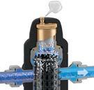

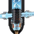


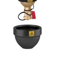
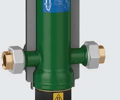
84 IMPROVE PERFORMANCE IN FOUR WAYS MULTI-FUNCTION 5495 SERIES MULTI-FUNCTION SEPARATOR Combines four different functional components into one separator. 1) Hydraulic Separation 2) Air Separation 3) Dirt Separation 4) Magnetic Separation of ferrous particles
AIR CONDITIONING. Carrier Corporation 2002 Cat. No
 AIR CONDITIONING Carrier Corporation 2002 Cat. No. 020-016 1. This refresher course covers topics contained in the AIR CONDITIONING specialty section of the North American Technician Excellence (NATE)
TOTAL SYSTEM EFFICIENCY: SYSTEM APPLICATIONS & DESIGNS. David Grassl PE Mechanical Engineer Principal
 TOTAL SYSTEM EFFICIENCY: SYSTEM APPLICATIONS & DESIGNS David Grassl PE Mechanical Engineer Principal Similar to traditional boiler systems, condensing boiler systems have many designs they can operate
COMMERCIAL HVAC SYSTEMS Water Source Heat Pump Systems
 COMMERCIAL HVAC SYSTEMS Water Source Heat Pump Systems Technical Development Program Technical Development Programs (TDP) are modules of technical training on HVAC theory, system design, equipment selection
Air-to-Water Heat Pumps + Boilers A Dynamic Duo
 Authored by John Siegenthaler September 2016 Edition Air-to-Water Heat Pumps + Boilers A Dynamic Duo Electrically powered heat pumps, available in many varieties, will play an increasingly important role
SECTION 5 COMMERCIAL REFRIGERATION UNIT 21 EVAPORATORS AND THE REFRIGERATION SYSTEM UNIT OBJECTIVES 3/22/2012 REFRIGERATION
 SECTION 5 COMMERCIAL REFRIGERATION UNIT 21 EVAPORATORS AND THE REFRIGERATION SYSTEM UNIT OBJECTIVES After studying this unit, the reader should be able to Define high-, medium-, and low-temperature refrigeration.
InDEX. A Technical Journal from Caleffi Hydronic Solutions
 Caleffi Caleffi North North America, America, Inc. Inc. 9850 3883 South W. Milwaukee 54 th Street Rd Franklin, Milwaukee, WI 53132 Wisconsin 53208 T: 414.421.1000 414.238.2360 F: F: 414.421.2878 414.238.2366
INTRODUCTION HVAC BASICS AND HVAC SYSTEM EFFICIENCY IMPROVEMENT SECTION O 4/19/2012
 HVAC BASICS AND HVAC SYSTEM EFFICIENCY IMPROVEMENT SECTION O INTRODUCTION HVAC systems or Heating, Ventilating and Air-Conditioning systems control the environment for people and equipment in our facilities.
Outdoor Reset Control Theory FULL versus PARTIAL reset
 Outdoor Reset Control Theory FULL versus PARTIAL reset Conventional boilers must be protected against sustained operation at low temperatures. If not, they will be damaged by sustained flue gas condensation.
The electrical wattage needed by the circulator is:
 The electrical wattage needed by the circulator is: w e = 0.4344 f P n w/w A current-generation wet-rotor circulator has a maximum wire-towater efficiency in the range of 25 percent. If we put the data
AIR-CONDITIONING SYSTEMS AND APPLICATIONS. Abdullah Nuhait Ph D. King Saud University
 AIR-CONDITIONING SYSTEMS AND APPLICATIONS Abdullah Nuhait Ph D. King Saud University AIR-CONDITIONING SYSTEMS Earliest air conditioning system used only for heating (winter) Provided heated air for comfort
100% Outdoor Air Dehumidification Methods
 Technical Bulletin 16 100% Outdoor Air ehumidification Methods I NTROUCTION As consulting engineers and end users implement the ASHRAE 6 ventilation code, they are faced with selecting an appropriate method
BASIC HEAT PUMP THEORY By: Lloyd A. Mullen By: Lloyd G. Williams Service Department, York Division, Borg-Warner Corporation
 INTRODUCTION In recent years air conditioning industry technology has advanced rapidly. An important byproduct of this growth has been development of the heat pump. Altogether too much mystery has surrounded
Technical Development Program COMMERCIAL HVAC SYSTEMS. Water Source Heat Pump Systems PRESENTED BY: Ray Chow. Sales Engineer
 Technical Development Program PRESENTED BY: COMMERCIAL HVAC SYSTEMS Water Source Heat Pump Systems Ray Chow Sales Engineer TDP Updates Menu Section 1 Section 2 Section 3 Section 4 Section 5 Section 6 Section
State of the art building simulation software... Frenger Radiant chilled beam performance at 1 Shelly St - Sydney
 Frenger Radiant chilled beam performance at 3D Model Creation Daylight Analysis Comparison of the performance of various HVAC systems at 1 Shelly St, Sydney VAV fancoil Active chilled beam Passive chilled
ENGINEERING. Edition No. 13 October 2002
 Edition No. 13 October 2002 ENGINEERING S Y S T E M S O L U T I O N S W e at McQuay are very proud of our tradition of producing industry leading water source heat pumps. Our heritage stretches back more
Sustainable Techniques in Refrigerated Space
 Sustainable Techniques in Refrigerated Space Sustainability and high performance of refrigerated space used for the preservation of perishable product capitalizes on conservation techniques which reduce
FAST AND ROBUST BUILDING SIMULATION SOFTWARE. Chilled Beam Performance: 1 Shelly Street, Sydney
 FAST AND ROBUST BUILDING SIMULATION SOFTWARE Chilled Beam Performance: 1 Shelly Street, Sydney 3D Model Creation 1 Shelley Street, Sydney 3D Model Creation 1 Shelley Street, Sydney Daylight Analysis 1
Air-Cooling Evaporators
 Air-Cooling Evaporators Types of construction Circuit Configurations Methods of Refrigerant Feed Methods of Air Circulation Methods of Defrost Type of Construction Bare tube Finned Tube Plate-surface Bare
2013 Guideline for Specifying the Thermal Performance of Cool Storage Equipment. AHRI Guideline T (I-P)
") 2013 Guideline for Specifying the Thermal Performance of Cool Storage Equipment AHRI Guideline T (I-P) IMPORTANT SAFETY DISCLAIMER AHRI does not set safety standards and does not certify or guarantee the
2013 Guideline for Specifying the Thermal Performance of Cool Storage Equipment AHRI Guideline T (I-P) IMPORTANT SAFETY DISCLAIMER AHRI does not set safety standards and does not certify or guarantee the
THERMAL ICE STORAGE: Application & Design Guide
 THERMAL ICE STORAGE: Application & Design Guide Table of Contents: 1. Introduction A. History of Thermal Energy Storage B. Operating and Cost Benefits 2. Applications A Fundamental System B. HVAC Cooling
Appendix 13. Categories of Cooling and Heating systems
 EcoShopping - Energy efficient & Cost competitive retrofitting solutions for Shopping buildings Co-funded by the European Commission within the 7 th Framework Programme. Grant Agreement no: 609180. 2013-09-01
Air Conditioning Clinic. Absorption Water Chillers One of the Equipment Series TRG-TRC011-EN
 Air Conditioning Clinic Absorption Water Chillers One of the Equipment Series TRG-TRC011-EN Absorption Water Chillers One of the Equipment Series A publication of The Trane Company Worldwide Applied Systems
Math. The latent heat of fusion for water is 144 BTU s Per Lb. The latent heat of vaporization for water is 970 Btu s per Lb.
 HVAC Math The latent heat of fusion for water is 144 BTU s Per Lb. The latent heat of vaporization for water is 970 Btu s per Lb. Math F. to C. Conversion = (f-32)*(5/9) C. to F. Conversion = C * 9/5 +
b.) Technical Information:
 Technical Information:") Section VI- Strategies a.) Summary: It is important for new construction designers to consider the heating, ventilation, and air conditioning needs within a building. There are many different systems,
Section VI- Strategies a.) Summary: It is important for new construction designers to consider the heating, ventilation, and air conditioning needs within a building. There are many different systems,
Session: HVAC 101 HVAC 101. Steve Sain Sain Engineering Associates, Inc. August 9, Rhode Island Convention Center Providence, Rhode Island
 Session: HVAC 101 HVAC 101 Steve Sain Sain Engineering Associates, Inc. August 9, 2016 Rhode Island Convention Center Providence, Rhode Island Why? 2 Acknowledgements 3 Disclaimer I m gonna shoot down
2. CURRICULUM. Sl. No.
 . CURRICULUM Sl. No. Code Title No. of Lecture Hours 1 RAC 001 Fundamentals of Refrigeration and Air 60 conditioning RAC 00 Psychrometry, Heat load Estimation for 70 Air conditioning and Refrigeration
SECTION 5 COMMERCIAL REFRIGERATION UNIT 22 CONDENSERS UNIT OBJECTIVES UNIT OBJECTIVES 3/22/2012
 SECTION 5 COMMERCIAL REFRIGERATION UNIT 22 CONDENSERS UNIT OBJECTIVES After studying this unit, the reader should be able to explain the purpose of the condenser in a refrigeration system. describe differences
union swing check valve spring loaded check valve purging valve pressure relief valve relief valve metered balancing valve
 VENT APPENDIX A: PIPING SYMBOL LEGEND GENERIC COMPONENTS CALEFFI COMPONENTS circulator circulator w/ ThermoBloc union circulator w/ swing check spring loaded balancing balancing w/ gate check globe s purging
Chilled Beams. Getting a Warmer Reception
 Chilled Beams Getting a Warmer Reception Gain an understanding of how chilled-beam technology works, the difference between active/passive chilled beams and potential applications for its use. B y G r
Refrigeration/Troubleshooting Manual
 Refrigeration/Troubleshooting Manual P.O. Box 245 Syracuse, NY 13211 www.roth-america.com 888-266-7684 P/N: 2300100910 Table of Contents: Section 1: Geothermal Refrigeration Circuits Overview... 2 Water-to-Air
BRINE CIRCULATED ICE THERMAL STORAGE SYSTEM DESIGN - CASE ILLUSTRATION - Partial Ice Storage for Air Conditioning Application
 1 BRINE CIRCULATED ICE THERMAL STORAGE SYSTEM DESIGN - CASE ILLUSTRATION - Partial Ice Storage for Air Conditioning Application By: T. S. Wan Date: Oct. 7, 1995 Copy Right 1995 by T. S. Wan All rights
A hydronic system controls comfort by delivering heated or cooled fluid to the conditioned space through pipes.
 Introduction to Hydronics A hydronic system controls comfort by delivering heated or cooled fluid to the conditioned space through pipes. Hydronic heating systems use hot water or steam to deliver the
SECTION 8 AIR SOURCE HEAT PUMPS UNIT 43 AIR SOURCE HEAT PUMPS
 SECTION 8 AIR SOURCE HEAT PUMPS UNIT 43 AIR SOURCE HEAT PUMPS UNIT OBJECTIVES After studying this unit, the reader should be able to Describe the operation of reverse-cycle refrigeration (heat pumps) Explain
CHAPTER 4. HVAC DELIVERY SYSTEMS
 CHAPTER 4. HVAC DELIVERY SYSTEMS 4.1 Introduction 4.2 Centralized System versus Individual System 4.3 Heat Transfer Fluids 4.4 CAV versus VAV Systems 4.5 Common Systems for Heating and Cooling 4.6 Economizer
HEAT PUMPS. Carrier Corporation GT72-01 Cat. No
 HEAT PUMPS Carrier Corporation 2003 GT72-01 Cat. No. 020-018 1. This refresher course covers topics contained in the HEAT PUMPS specialty section of the North American Technician Excellence (NATE) certification
Fundamental Principles of Air Conditioners for Information Technology
 Fundamental Principles of Air Conditioners for Information Technology By Tony Evans White Paper #57 Revision 2 Executive Summary Every Information Technology professional who is responsible for the operation
Geothermal Heating and Cooling Using Ground Source Heat Pumps. Prepared by: Steven Forrester, P.E. Principal
 Geothermal Heating and Cooling Using Ground Source Heat Pumps Prepared by: Steven Forrester, P.E. Principal A Little History on Geothermal and Heat Pumps Lord Kelvin came up with the idea for heat pumps
Richard Hiles ClimateMaster
 Minnesota Geothermal Heat Pump Association 2012 Properly Sizing Ground Source Heat Pump Systems Richard Hiles ClimateMaster Objective Properly Size and Select GSHP System for Low Operating Costs And Proper
HVAC Equipments and Systems
 PDHonline Course M322 (7 PDH) HVAC Equipments and Systems Instructor: A. Bhatia, B.E. 2012 PDH Online PDH Center 5272 Meadow Estates Drive Fairfax, VA 22030-6658 Phone & Fax: 703-988-0088 www.pdhonline.org
Summary Comparison of Simulation Program Features
 Summary Comparison of Simulation Program Features FEATURE DOE2.2 equest TRACE 700 HAP Public/Proprietary Public Domain Proprietary Proprietary Proprietary Simulation Method 8760 hours 8760 hours 8760 hours
Vapor-Compression Refrigeration
 Vapor-Compression Refrigeration condenser D C expansion device compressor A B evaporator Types of Heat Pumps water-source heat pumps water-to-water heat pump air-source heat pumps Cooling Heating
Appendix A. Glossary of Common Terms
 Glossary of Common Terms Glossary of Common Terms Absorption chiller A refrigeration machine using heat as the power input to generate chilled water. Adjustable speed drive A means of changing the speed
BOOK 1 OVERVIEW RD2XRT INSTALLATION AND OPERATION MANUAL. Table of Contents ABOUT BOOK 1:
 4510 Helgesen Drive, Madison, WI, 53718 608.221.4499, 800.627.4499, Fax: 608.221.2824 support@renewaire.com www.renewaire.com RD2XRT INSTALLATION AND OPERATION MANUAL BOOK 1 OVERVIEW ABOUT BOOK 1: This
Heat pump and energy recovery systems
 SBS5311 HVACR II http://ibse.hk/sbs5311/ Heat pump and energy recovery systems Ir. Dr. Sam C. M. Hui Faculty of Science and Technology E-mail: cmhui@vtc.edu.hk Oct 2017 Contents Basic concepts Air-to-air
Technical Development Program
 Technical Development Program PRESENTED BY: James Parker Insert your logo here AIR HANDLERS Coils: Direct Expansion Chilled Water and Heating Menu Section 1 Introduction Section 2 Typical Coil Applications
Daikin Blueprint: Delivering Hot Water with a Chiller
 Daikin Blueprint: Delivering Hot Water with a Chiller Analyzing the design of heat recovery on air-cooled chillers and the effect it has on building energy consumption By Paul Crisman Daikin Chiller Applications
A HOMEOWNERS HANDBOOK AIR CONDITIONING
 A HOMEOWNERS HANDBOOK AIR CONDITIONING By Everett H. Rawlings COOLING SYSTEMS Cooling systems have become known as air conditioning. Specifically, air conditioning includes the maintenance of proper temperature,
Single Zone System. One duct system Used mostly in small buildings Forced air system All spaces controlled by a single thermostat Single air return
 Single Zone System One duct system Used mostly in small buildings Forced air system All spaces controlled by a single thermostat Single air return Multi Zone System Used in small to medium sized buildings
Senior Thesis Centre Community Hospital East Wing Addition - Proposal Keith Beidel Mechanical Option 12/05/02 1
 Table of Contents Page Number(s) Executive Summary 2 Project Background 3 Proposed Depth Alternatives 4 Proposed Depth Redesign 5-7 Justification of Proposed Depth Redesign 8 Proposed Breath Redesign 9
DISTRIBUTION SYSTEMS. Water Piping and Pumps
 DISTRIBUTION SYSTEMS Water Piping and Pumps Technical Development Programs (TDP) are modules of technical training on HVAC theory, system design, equipment selection and application topics. They are targeted
PINNACLE SERIES DEDICATED OUTDOOR AIR SYSTEM ENERGY EFFICIENT DEHUMIDIFICATION
 ENERGY EFFICIENT DEHUMIDIFICATION PINNACLE SERIES DEDICATED OUTDOOR AIR SYSTEM Provides a very high degree of latent cooling using only a minimal amount of conventional cooling input Substantial energy
SERVICE ASSISTANT OVERVIEW FDSI Online Training
 Author: Dale T. Rossi Online Editor: Zachary Williams SERVICE ASSISTANT OVERVIEW FDSI Online Training May 5, 2009 Table Service Assistant Description... 2 Installing the Main Unit... 3 Ambient Temperature...
HVAC Systems What the Rater Needs to Know in the Field CALCS-PLUS
 HVAC Systems What the Rater Needs to Know in the Field This presentation used CASE* studies from the following *CASE Copy And Steal Everything HVAC Systems - What the Rater Needs to Know in the Field This
MECHANICAL ENGINEERING ME.2017 FUNDAMENTAL OF REFRIGERATION AND AIR CONDITIONING. Sample Questions and Answers
 MECHANICAL ENGINEERING ME.2017 FUNDAMENTAL OF REFRIGERATION AND AIR CONDITIONING Sample Questions and Answers CHAPTER 5 EVAPORATORS 1. What is Evaporator? Classify the various types of evaporator. Evaporator
For an administrative fee of $9.97, you can get an un-locked, printable version of this book.
 The System Evaluation Manual and Chiller Evaluation Manual have been revised and combined into this new book; the Air Conditioning and Refrigeration System Evaluation Guide. For an administrative fee of
Adelaide Homes Design Guide 4 - Winter warming
 Adelaide Homes Design Guide 4 - Winter warming Adelaide's temperate climate means home warming is required during winter. There are many efficient heating systems. The most economical method, however,
COMMERCIAL HVAC SYSTEMS Water Source Heat Pump Systems
 COMMERCIAL HVAC SYSTEMS Water Source Heat Pump Systems Technical Development Program Technical Development Programs (TDP) are modules of technical training on HVAC theory, system design, equipment selection
General HVAC Recommendations
 General HVAC Recommendations DESIGN GUIDELINES FOR ENERGY EFFICIENT HVAC SYSTEMS Thank you for your interest in energy efficiency! Energy efficient heating, ventilation, and air conditioning (HVAC) equipment
Dear Hydronic Professional, Dear Hydronic Professional,
 Caleffi Caleffi North North America, America, Inc. Inc. 9850 3883 South W. Milwaukee 54 th Street Rd Franklin, Milwaukee, WI 53132 Wisconsin 53208 T: 414.421.1000 414.238.2360 F: F: 414.421.2878 414.238.2366
Air Conditioning and process cooling Energy Components at a Glance
 Energy Components at a Glance What is it? A means of providing cooling with mechanical refrigeration equipment. Where is it found? Chilled water is found in many plants, non-existent in others. Essential
Heat Pumps COMFORT NEED IT. When You
 Heat Pumps COMFORT When You NEED IT COMFORT When You NEED IT SpacePak s Solstice heat pumps are air-to-water reverse cycle heat pumps that use the comfort of Hydronics as the primary source for both heating
BOOK 1 OVERVIEW RD2XIN INSTALLATION AND OPERATION MANUAL. Table of Contents ABOUT BOOK 1:
 4510 Helgesen Drive, Madison, WI, 53718 608.221.4499, 800.627.4499, Fax: 608.221.2824 support@renewaire.com www.renewaire.com RD2XIN INSTALLATION AND OPERATION MANUAL BOOK 1 OVERVIEW ABOUT BOOK 1: This
ENGINEERING BULLETIN. Overview of Chilled Beam Technology. Purpose. Summary. Theory
 Overview of Chilled Beam Technology Purpose Chilled beam technology is new to the United States but has been used in Europe since the 1950 s. Chilled beams can reduce energy costs, improve indoor air quality,
A Technical Introduction to Cool Thermal Energy Storage Commercial Applications
 A Technical Introduction to Cool Thermal Energy Storage Commercial Applications Cool Thermal Energy Storage is a new application of an old idea that can cut air conditioning energy costs in half while
HVAC Equipment and Systems
 HVAC Equipment and Systems Course No: M08-004 Credit: 8 PDH A. Bhatia Continuing Education and Development, Inc. 9 Greyridge Farm Court Stony Point, NY 10980 P: (877) 322-5800 F: (877) 322-4774 info@cedengineering.com
PRESSURE-ENTHALPY CHARTS AND THEIR USE By: Dr. Ralph C. Downing E.I. du Pont de Nemours & Co., Inc. Freon Products Division
 INTRODUCTION PRESSURE-ENTHALPY CHARTS AND THEIR USE The refrigerant in a refrigeration system, regardless of type, is present in two different states. It is present as liquid and as vapor (or gas). During
Dehumidifying with Dedicated Outdoor Air
 Dehumidifying with Dedicated Outdoor Air System Configurations Figure 71. Configurations for dedicated outdoor-air systems A dedicated outdoor-air handler separately filters, cools, dehumidifies, heats,
High Efficiency Heating and Cooling Systems for Community Colleges Kirk Mescher, PE, LEED AP Principal ICCCFO
 High Efficiency Heating and Cooling Systems for Community Colleges Kirk Mescher, PE, LEED AP Principal ICCCFO 2012 1 Learning Objectives for this Session Get acquainted with typical systems used in the
Distribution Efficiency: The Under-appreciated Benefit of Hydronics
 International Centre, Mississauga, Ontario good craftsmanship, wrong approach Distribution Efficiency: The Under-appreciated Benefit of Hydronics Btu / hr presented by: John Siegenthaler, P.E. Appropriate
By Thomas H. Durkin, P.E., Member ASHRAE, and James B. (Burt) Rishel, P.E., Fellow/Life Member ASHRAE
 Rishel, P.E., Fellow/Life Member ASHRAE") By Thomas H. Durkin, P.E., Member ASHRAE, and James B. (Burt) Rishel, P.E., Fellow/Life Member ASHRAE T he advent of the small scroll or screw chiller, capable of producing condenser water as high as 140
By Thomas H. Durkin, P.E., Member ASHRAE, and James B. (Burt) Rishel, P.E., Fellow/Life Member ASHRAE T he advent of the small scroll or screw chiller, capable of producing condenser water as high as 140
System Design, Commissioning, Operation
 PART 3: CO 2 as a Refrigerant System Design, Commissioning, Operation Service This series continues with the introduction of transcritical, cascade and secondary systems; how each system works; and compares
CTI Sponsored Educational Program
 Presented By: Kent Martens SPX Cooling Technologies, Inc. Slide No.: 1 CTI Mission Statement To advocate and promote the use of environmentally responsible Evaporative Heat Transfer Systems (EHTS) for
terminal units only provide sensible cooling, a separate dehumidification system is usually needed.
 providing insights for today s hvac system designer Engineers Newsletter volume 44 3 Dual-Temperature Chiller Plants This Engineers Newsletter describes several dual-temperature configurations that can
Refrigeration and. Modern. Air Conditioning. Bracciano, BS, M.Ed., Ed. Sp. Alfred F. Andrew D. Althouse, BS, (ME), MA. Carl H. Tumquist, BS, (ME), MA
, MA. Carl H. Tumquist, BS, (ME), MA") Modern Refrigeration and Air Conditioning by Andrew D. Althouse, BS, (ME), MA Technical-Vocational Education Consultant Life Member, American Society of Heating, Refrigeration, and Air-Conditioning Engineers
Modern Refrigeration and Air Conditioning by Andrew D. Althouse, BS, (ME), MA Technical-Vocational Education Consultant Life Member, American Society of Heating, Refrigeration, and Air-Conditioning Engineers
UNIT 4: REFRIGERATION PRINCIPLE
 UNIT 4: REFRIGERATION PRINCIPLE 4.1 Introduction i. Buildings are essentially enclosed spaces designed for the purpose of accommodating occupants and their activities. ii. Thermal comfort is incorporated
RN/RQ. Series PACKAGED ROOFTOP UNITS, AIR-SOURCE HEAT PUMPS, WATER-SOURCE/ GEOTHERMAL HEAT PUMPS, & OUTDOOR AIR HANDLING UNITS.
 RN/RQ Series PACKAGED ROOFTOP UNITS, AIR-SOURCE HEAT PUMPS, WATER-SOURCE/ GEOTHERMAL HEAT PUMPS, & OUTDOOR AIR HANDLING UNITS RQ Series Features: Air-cooled or water-cooled condenser, with unit capacities
MECHANICAL SCIENCE Module 2 Heat Exchangers
 Department of Energy Fundamentals Handbook MECHANICAL SCIENCE Module 2 Heat Exchangers Heat Exchangers DOE-HDBK-1018/1-93 TABLE OF CONTENTS TABLE OF CONTENTS LIST OF FIGURES... ii LIST OF TABLES... iii
A Treatise on Liquid Subcooling
 A Treatise on Liquid Subcooling While the subject of this article is Liquid Refrigerant Subcooling, its affect on the operation of the thermostatic expansion valve (TEV), and ultimately on system performance
IDL20e (2 way discharge) IDS60e (4 way discharge) Inffusers. UDI (vertical discharge) Frequently Asked Questions
 IDS60e (4 way discharge) Inffusers. UDI (vertical discharge) Frequently Asked Questions") IDL20e (2 way discharge) IDS60e ( way discharge) Frequently Asked Questions UDI (vertical discharge) Inffusers INFFUSER FREQUENTLY ASKED QUESTIONS The following are frequently asked questions (FAQ s) on
IDL20e (2 way discharge) IDS60e ( way discharge) Frequently Asked Questions UDI (vertical discharge) Inffusers INFFUSER FREQUENTLY ASKED QUESTIONS The following are frequently asked questions (FAQ s) on
Benefits Offered by Passive Dehumidification Wheel Speed Control
 Benefits Offered by Passive Dehumidification Wheel Speed Control White paper By John Fischer Benefits Offered by Passive Dehumidification Wheel Speed Control The most significant advantage of the Pinnacle
Chiller Plant Design. Julian R. de Bullet President debullet Consulting
 Chiller Plant Design Julian R. de Bullet President debullet Consulting 703-483-0179 julian@debullet.com This ASHRAE Distinguished Lecturer is brought to you by the Society Chapter Technology Transfer ASHRAE
GEOTHERMAL DESIGN GUIDE
 GEOTHERMAL DESIGN GUIDE BENEFITS OF THE BULLDOG SYSTEM CGC Version CGC Group of Companies Incorporated 2018 CONTENTS INTRODUCTION... 2 CHALLENGES FACING CONVENTIONAL GSHP SYSTEMS... 3 FACTORS WHICH IMPACTS
Refrigeration Systems and Accessories
 As with the Chapter Review Tests and the Final Exam, the tests your understanding of the materials underlying the learning objectives. After you ve reviewed your answers to the Chapter Review Tests, try
COMMERCIAL HVAC EQUIPMENT Coils: Direct Expansion, Chilled Water, and Heating
 COMMERCIAL HVAC EQUIPMENT Coils: Direct Expansion, Chilled Water, and Heating Technical Development Program Technical Development Programs (TDP) are modules of technical training on HVAC theory, system
Use this Construction/HVAC Glossary to answer the questions below.
 www.garyklinka.com Page 1 of 21 Instructions: 1. Print these pages. 2. Circle the correct answers and transfer to the answer sheet on the second last page. 3. Page down to the last page for the verification
HVAC Water chiller selection and optimisation of operation
 HVAC Water chiller selection and optimisation of operation Introduction Water-chiller is a broad term describing an overall package that includes an electrical control panel, refrigeration plant, water
SECTION TESTING, ADJUSTING, AND BALANCING FOR HVAC
 PART 1 GENERAL 1.01 SECTION INCLUDES SECTION 23 0593 TESTING, ADJUSTING, AND A. Testing, adjustment, and balancing of air systems. B. Testing, adjustment, and balancing of hydronic, steam, and refrigerating
EASY$ TIP SHEETS. Energy Advice Saving Yukoners Money. How hydronic heating systems work
 EASY$ TIP SHEETS Energy Advice Saving Yukoners Money Quick Links How hydronic heating systems work Advantages Disadvantages Design alternatives Baseboard convectors Residential Hydronic Heating A residential
AND AIR-CONDITIONING. Dr Ali Jawarneh Department of Mechanical Engineering Hashemite University
 Chapter 14 GAS VAPOR MIXTURES AND AIR-CONDITIONING Dr Ali Jawarneh Department of Mechanical Engineering Hashemite University 2 Objectives Differentiate between dry air and atmospheric air. Define and calculate
COMMERCIAL HVAC PACKAGED EQUIPMENT. Split Systems
 COMMERCIAL HVAC PACKAGED EQUIPMENT Split Systems Technical Development Programs (TDP) are modules of technical training on HVAC theory, system design, equipment selection and application topics. They are
KE2 EvaporatorEfficiency Theory of Operation
 Theory T.1.1 June 011 TM thermsolutions ENTER BACK KE Therm Solutions, Advanced Energy Saving Technology for Commercial Refrigeration and AC Systems Page Table of Contents Basic Refrigeration System Evaporator
NON-REVERSING, 100% OUTSIDE AIR HEAT PUMP FOR HEATING AND COOLING
 NON-REVERSING, 100% OUTSIDE AIR HEAT PUMP FOR HEATING AND COOLING Danny Hall, National Sales Manager, Desert Aire Corp., Milwaukee, WI USA Traditionally, a heat pump has relied on a reversing valve system
Chiller Plant Design. Application Guide AG McQuay International. Elevation Difference. Column Height When Pump Is Off
 Application Guide AG 31-003-1 Chiller Plant Design 51.5F Return Water To Chiller Two 400 Ton Chillers Each At 300 Tons (Balanced Load) 51.5F 480 gpm Flow Through Decoupler 44F 54F Building Load 600 Tons
Thomas J Kelly. Fundamentals of Refrigeration. Sr. Engineering Instructor Carrier Corporation. August 20, Page number: 1.
 Thomas J Kelly Sr. Engineering Instructor Carrier Corporation August 20, 2003 1 SESSION OBJECTIVES At the conclusion of this session you should be able to: 1. Describe the basics principles of refrigeration
S.A. Klein and G.F. Nellis Cambridge University Press, 2011
 12.A-1 A mixture of helium and water vapor is flowing through a pipe at T= 90 C and P = 150 kpa. The mole fraction of helium is y He = 0.80. a.) What is the relative humidity of the mixture? b.) What is
Dear Hydronic and Plumbing Professional, Dear Hydronic Professional,
 Caleffi North America, Inc. 9850 South 54 th Street Franklin, WI 53132 T: 414.421.1000 F: 414.421.2878 A Technical Journal from Caleffi Hydronic Solutions CALEFFI NORTH AMERICA, INC 3883 W. Milwaukee Rd
DX Units. Ranging from 15 to 750 tons and 1,000 to 300,000+ CFM
 D Units Ranging from 15 to 750 tons and 1,000 to 300,000+ CFM INDUSTRY-LEADING HVAC MANUFACTURER Nortek Air Solutions is the largest custom HVAC manufacturer in North America, with a combined total of
Best Practices for Condensing Boilers
 ASHRAE www.ashrae.org. Used with permission from ASHRAE Journal at www.cleaverbrooks.com. This article may not be copied nor distributed in either paper or digital form without ASHRAE s permission. For
Development of a Psychrometric Test Chamber. Michael J. Swedish. Associate Professor Mechanical Engineering Department Milwaukee School of Engineering
 Session 2633 Development of a Psychrometric Test Chamber Michael J. Swedish Associate Professor Mechanical Engineering Department Milwaukee School of Engineering Acknowledgments The design of the Psychrometric
2009 IECC Commercial Mechanical Requirements
 BUILDING ENERGY CODES UNIVERSITY 2009 IECC Commercial Mechanical Requirements Ken Baker PNNL-SA-66171 Learning(Objec-ves(( ( 1. Find(minimum(equipment(efficiency(requirements( and(recite(at(least(3(common(terms(for(measuring(