LV Model Water Source Heat Pump
|
|
|
- Justin Wilkins
- 5 years ago
- Views:
Transcription


1 LV Model Water Source Heat Pump 1/2 to 6 ton boschheatingandcooling.com and coolin g.c om 1 The option-rich, water-to-air LV offers one of the smallest cabinets in the industry, making it a great choice for replacement and new construction projects. LV MODEL UP TO 16.9 EER GLHP UP TO. COP WSHP Commercial Sales Catalog boschheatingandcooling.com Subje jec ect to c han ge wit thou t p rio ior noti otice.
2 1 LV Model Commercial Geothermal Heat Pumps Table of Contents MODEL NOMENCLATURE...2 CERTIFIED PERFORMANCE DATA... FHP EQUIPMENT... ADVANTAGES OF FHP s TECHNOLOGY... LV MODEL FEATURES, FUNCTIONS AND BENEFITS...-7 Cabinet... Quiet Operation...6 Serviceability...6 Unit Configurations...6 Filter Racks and Options...6 Optional MERV-8 and -1 Filter...6 FAN MOTOR...7 Permanent Split Capacitor Motors (PSC)...7 ECM Constant Torque Motor (Optional)...7 ECM Constant Airflow Motor...7 Hanging Brackets...7 Water Connections...7 Two-Position Water Valve...7 Refrigerant Circuit...7 Evaporator Coil and DuoGuard TM...8 Blower Housing...8 Unit Protection Module UPM CONTROL BOARD FEATURES ADDITIONAL OPTIONS...10 Hot Gas Reheat...10 Hot Gas Reheat Control Options...11 Special Considerations...11 Low Temperature Well Water...11 Indoor Pool Dehumidifying During Winter Months...11 Sequence of Operation - Modulating Hot Gas Reheat (MHGRH)...11 Hot Gas Bypass...11 Psychrometric Chart...12 DDC Controls...12 DDC Room Sensors...12 DDC Zone Sensors...1 Waterside Economizer Common Waterside Economizer Applications...1 Fluid Flow...1 Aquastat...14 Air Side Pressure Drop...14 Fluid Differential Pressure Switch...14 Energy Management Switch (EMS)...14 OTHER OPTIONS...1 ACCESSORIES...1 Thermostats...1 Hose Kits...1 UNIT CONFIGURATION DIAGRAMS...16 SYSTEMS...17 Water Source Cooling Tower/Boiler Systems...17 Geothermal Systems...17 Earth Coupling Options Vertical Ground Loop System...18 Horizontal Ground Loop System...18 Surface Water, Lake or Pond System...19 Well Water System...19 TYPICAL HEAT PUMP OPERATION...19 Cooling Mode...19 Heating Mode...19 TYPICAL UNIT INSTALLATION...20 Water-to-Air Heat Pump Cycle - Cooling...20 Water-to-Air Heat Pump Cycle - Heating...20 Unit Location...20 Vertical Unit Installation...20 Horizontal Unit Installation...21 Ductwork & Sound Attenuation Considerations...21 Piping...22 Condensate Drain Piping...22 Operating Limits Cooling & Heating EQUIPMENT SELECTION...2 ANTIFREEZE CORRECTION DATA...24 WATERSIDE PRESSURE DROP...24 CAPACITY DATA LV007 (00 CFM)...2 LV009 (0 CFM)...26 LV012 (400 CFM)...27 LV01 (00 CFM)...28 LV018 (60 CFM)...29 LV024 (80 CFM)...0 LV00 (90 CFM)...1 LV06 (1200 CFM)...2 LV041 (110 CFM)... LV042 (100 CFM)...4 LV048 (1600 CFM)... LV060 (2000 CFM)...6 LV070 (2200 CFM)...7 UNIT ELECTRICAL DATA...8 Standard Blower Motor...8 ECM Constant Torque...9 ECM Constant Airflow (Variable Speed)...40 BLOWER PERFORMANCE CFM...41 Standard Blower Motor...41 ECM Constant Torque...42 ECM Constant Airflow (Variable Speed)...4 PHYSICAL DATA...44 HORIZONTAL CABINET CORNER WEIGHTS...4 VERTICAL UNIT DIMENSIONS...46 HORIZONTAL UNIT DIMENSIONS...47 COUNTERFLOW UNIT DIMENSIONS...48 GUIDE SPECIFICATION
3 2 LV Model Commercial Geothermal Heat Pumps boschheatingandcooling.com 2 Model Nomenclature LV 06 1 VT C F L T P U A MODEL: LV NOMINAL CAPACITY: 007, 009, 012, 01, 018, 024, 00, 06, 041, 042, 048, 060, 070 VOLTAGE DESIGNATION: 0-11/60/1 (LV012 only) 1-208/60/1 & 20/60/1 2-26/60/1-208/60/ & 20/60/ 4-460/60/ - 7/60/ CABINET CONFIGURATION: VT - Vertical HZ - Horizontal CF - Counterflow (Downflow) COAX OPTIONS: C - Copper N - Cupro-Nickel REVISION LEVEL: A - Current AIR COIL OPTIONS: U - Uncoated Air Coil D - DuoGuard Air Coil FAN/MOTOR OPTIONS: P - Standard PSC A - ECM Constant Airflow T - ECM Constant Torque DISCHARGE AIR CONFIGURATION: T - Top S - Straight E - End B - Bottom RETURN AIR CONFIGURATION: L - Left R - Right WATER CONNECTIONS: F - Front
4 LV Model Commercial Geothermal Heat Pumps boschheatingandcooling.com Certified Performance Data Model Fluid Flow Rate Cooling (WLHP) AHRI/ANSI Performance Data Water Temperatures 86 F 68 F 77 F 2 F Water Loop Ground Loop and Efficiency Data PSC motor with TXV EER (WLHP) Heating (WLHP) COP (WLHP) Cooling (GLHP) EER (GLHP) Heating (GLHP) COP (GLHP) LV , , , , LV , , , , LV012 10, , , , LV , , , ,00.0 LV , , , ,00.0 LV , , , , LV , , , ,900.0 LV06 9 7, , , ,900.0 LV , , , , LV , , , ,000.0 LV , , , , LV , , , , Model Fluid Flow Rate AHRI/ANSI Performance Data Water Temperatures 86 F 68 F Water Loop and Efficiency Data PSC motor with capillary tube Cooling (WLHP) EER (WLHP) Heating (WLHP) COP (WLHP) LV , ,800.0 LV , , LV012 10, , LV , , LV , , LV , , LV , , LV06 9 7, , LV , , LV , , LV , , LV , , Tabulated performance data is at noted water temperatures and entering air conditions of 80.6 F DB/66.2 F WB at AHRI/ANSI rated CFM with 1" disposable filter. GLHP ratings require an extended range option. ECM motors can be either constant torque or constant CFM.
5 boschheatingandcooling.com 4 Model Fluid Flow Rate Cooling (WLHP) AHRI/ANSI Performance Data Water Temperatures 86 F 68 F 77 F 2 F Water Loop Ground Loop and Efficiency Data ECM Motor with TXV (Option) EER (WLHP) Heating (WLHP) COP (WLHP) Cooling (GLHP) EER (GLHP) Heating (GLHP) COP (GLHP) LV01 4 1, , , ,700.0 LV , , , , LV , , , , LV00 7 0, , , , LV06 9 8, , , ,00.60 LV , , , ,00.60 LV , , , ,100.0 LV , , , , LV , , , ,200.0 LV , , , ,000.0 Model Fluid Flow Rate AHRI/ANSI Performance Data Water Temperatures 86 F 68 F Water Loop and Efficiency Data ECM Motor with capillary tube (Option) Cooling (WLHP) EER (WLHP) Heating (WLHP) COP (WLHP) LV01 4 1, , LV , , LV , , LV00 7 0, , LV06 9 8, , LV , , LV , , LV , , LV , , LV , , Tabulated performance data is at noted water temperatures and entering air conditions of 80.6 F DB/66.2 F WB at AHRI/ANSI rated CFM with 1" disposable filter. GLHP ratings require an extended range option. ECM motors can be either constant torque or constant CFM.


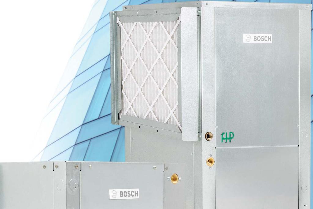
6 LV Model Commercial Geothermal Heat Pumps FHP Equipment Specializing in efficient green technology for commercial heating and cooling products. FHP products are one of the leading Geothermal and Water Source heat pumps in the market, which assures that you are buying a unit that you can trust. Bosch Thermotechnology Corp. is dedicated to providing highly efficient heating and cooling solutions to the private and public sectors. Bosch Thermotechnology Corp. is always on the forefront of product development and innovative design to optimize the performance of FHP units. Our products are designed and manufactured to the highest quality, reflecting the no-compromise standards for which FHP and Bosch are renowned in order to provide our customers with the highest level of satisfaction and comfort. The variety of options, energy efficiency, and uncompromising quality of all FHP products makes them the ideal choice for the commercial new construction market and the ease of designing into tight retrofit spaces of buildings. Advantages of FHP Technology Low installation costs Lower operating costs Flexibility and comfort Energy efficiency Space savings Superior quality Quiet operation LV Model Models from 1/2 through 6 tons Horizontal, Vertical, and Counterflow Configurations* The LV Model is a cost-effective, single stage water source heat pump designed for commercial retrofit and new construction applications. *Not all model sizes are available in all configurations. Consult the charts in this catalog for details. Features, Functions and Benefits found Cabinet The LV unit cabinetry is constructed using heavy-gauge, galvanized steel. This steel provides superior corrosion protection for units located indoors. All interior surfaces are lined with 1/2" thick, 1. lb./cu. ft. density, Micromat insulation for thermal insulation and acoustical attenuation. This insulation is non-combustible, non-hydroscopic and does not support fungal growth. Insulation meets NFPA 90A and 90B for fire protection and is certified to meet the GREENGUARD Indoor Air Quality Standard for Low Emitting Products. Protection against corrosion is a feature in the LV unit. A stainless steel drain pan will last the lifetime of the unit and resist corrosion and cracking that may occur with steel or plastic materials.
 Quiet Operation Noise reduction")


 and to further attenuate low frequency noise from the")


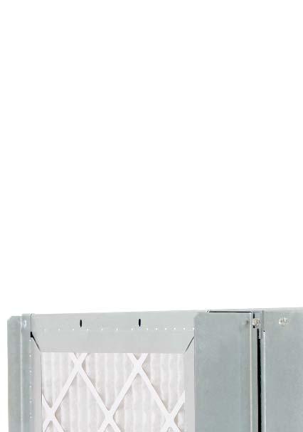
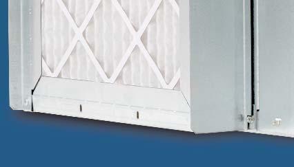
7 boschheatingandcooling.com 6 MERV-8 or MERV-1 Filter Option 2" 4-Sided Filter Rack Option Schrader Charging Valves Closed Cell Foam Insulation (Optional) Quiet Operation Noise reduction is a critical consideration of the unit design. All LV units have a distinct floating base pan; the compressor is mounted on a heavy steel plate which rests on a high density rubber pad on the base of the unit. In addition, compressors are mounted on rubber grommets. This double isolation, distinct to FHP equipment, is standard in all LV units preventing vibration and noise transmission from the compressor to the unit structure, resulting in exceptionally quiet operation. The LV offers optional 1/2" thick, closed cell foam insulation to help aid indoor air quality (IAQ) and to further attenuate low frequency noise from the compressor compartment. The closed cell foam insulation option is available in all unit sizes. For additional sound attenuation, an optional compressor blanket is available on unit sizes 024 and above. Serviceability All units are designed to be serviced from the front of the unit. Schrader valves for high and low pressure gauges and the electrical box components are easily accessible for diagnosing and servicing the unit. Insulated bulkheads in all units, separate the compressor section from the blower section, allowing the unit to be serviced during operation. Large removable panels aid in servicing the unit, when necessary. Separate electrical knockouts in the unit corner post allow for easy and safe routing of high and low voltage lines to the inside of the cabinet. Unit Configurations All units are available in horizontal, vertical and counterflow configurations. Additionally, several options of return air and supply air are offered as standard, providing configuration flexibility. Filter Racks and Options Units come standard with a 1" filter rack and construction filter. A 2" four-sided filter rack and pleated filter is optional and greatly improves air filtration. Filter doors allow for easy routine maintenance and changing of the air filter. A 1" return duct collar is integral to the filter rack eliminating the need for field mounted duct collars. MERV-8 and MERV-1 Filters The optional MERV-8 or -1 filter is most advantageous for premium air filtration on commercial HVAC projects. High efficiency filtration is a cost-effective way of upgrading air quality while maintaining low pressure drop and sustaining long service life. These filters effectively remove up to 98% of airborne matter, such as fine particulates, bacteria, smoke, gases and allergens including dust mites, pollen, mold spores, dust and smog. MERV-8 and MERV-1 rated filters are a minimum requirement for EQ credits.1 and on LEED projects. With the standard ECM constant airflow motor the LV is prepared to handle higher external pressure drops when utilizing the higher efficiency MERV-1 filters. Standard Optional
 is a PSC motor. For all models other than 7 V units, the supplied motor is a three speed motor.")


8 7 LV Model Commercial Geothermal Heat Pumps Constant Airflow ECM Option Constant Torque ECM Option 2-Way Valve with Actuator Coax Coil Fan Motor Permanent Split Capacitor Motors (PSC) The standard motor for all LV model heat pumps (except size 060) is a PSC motor. For all models other than 7 V units, the supplied motor is a three speed motor. 7 V motors are single speed. ECM Constant Torque Motor (Optional) The LV s constant torque blower motor option offers improved efficiency (up to %) over the standard PSC motor. This motor is similar in function to a PSC, but can handle up to 1 in.w.g. external static pressure making it a wise choice for high filtration applications. These motors are available in unit sizes 01 to 070. This ECM motor option is an excellent choice for retrofit. The constant-torque motors do not require a neutral wire for 460/ power. ECM Constant Airflow Motor The LV s new high efficiency ECM motor option, available in 1/hp to 1hp, provides constant airflow in a wide static pressure range up to 1 in.w.g. Available in unit sizes 01 to 070, this motor is a great choice in high filtration applications, such as MERV-1. The motor has a soft start/stop feature, keeping noise to a minimum. LV units outfitted with any ECM motor can see an efficiency boost with up to 1.8 additional points of EER. Passive dehumidification can be achieved with the constant airflow ECM by reducing nominal airflow by 1%. This control feature lowers air coil temperature and prevents over-cooling of the space when in dehumidification mode. IMPORTANT NOTE: The constant airflow ECM requires a neutral wire in a 460V application. Hanging Brackets All horizontal units come standard with hanging bracket kits for suspending the unit from field supplied hanger rods. These kits include heavy-duty steel brackets and rubber grommets for sound and vibration isolation from the building structure. Water Connections All water connections are heavy-duty bronze FPT fittings securely fastened to the unit corner post. This allows connecting to a flexible hose kit without the use of a backup wrench making for easier, faster installation. Two-Position Water Valve The two-position motorized water valve is optional on all unit sizes and is a great energy savings option. The valve opens to allow 100% fluid flow through the coaxial heat exchanger only when there is a call for cooling or heating. Closing off fluid flow to the unit when there is no call for cooling or heating reduces system operating costs, when using variable speed pumping, by reducing the speed of the primary loop pumps. Refrigerant Circuit LV units are designed using the optimum combination of compressor, water and air coils to provide peak performance. LV units are rated to withstand 600 PSIG working refrigerant pressure and 400 PSIG working water pressure. Heavy-duty heat pump compressors are used in all units. Rotary, reciprocating and scroll compressors offer optimum performance for each unit size.
 Blower Housing (with Removable Inlet Ring) Refrigerant to water heat exchangers are coaxial tube-intube type providing a robust")


9 boschheatingandcooling.com 8 Compressors Tin Plated with Coated Fin Evaporator Coil (Optional) Blower Housing (with Removable Inlet Ring) Refrigerant to water heat exchangers are coaxial tube-intube type providing a robust construction, ensuring years of trouble free operation. Coaxial coils are selected and designed for peak performance, offering the best combination of low water pressure drop and maximum heat transfer in both the cooling and heating modes. Standard coaxial coils have a copper interior water tube and a steel outer shell. Optional Cupro-Nickel coils are available for applications where the water is of lower quality. In geothermal applications where fluid temperatures can drop below the dew point of the surrounding air, optional insulation is available to prevent water coils and refrigerant piping from sweating. Evaporator Coil and DuoGuard TM (Option) Air handling sections come standard with a copper tube aluminum fin evaporator coil. Available as an option is the DuoGuard TM evaporator coil protection system. DuoGuard TM Protection - Tin Electro-Plated Copper Tubing with High-Tech Polymer Coated Aluminum Fins will aid in protecting the evaporator coil from most forms of corrosive elements in the airstream. The tin plating provides a best-in-class protection of the copper tubing from formicary corrosion while the fin coating provides protection against salt spray and other corrosive elements. DuoGuard TM protected coils are able to exceed 1000 hours salt spray per ASTM standard B-117. Air side refrigerant coils have copper tubes, aluminum fins and side plates to prevent corrosion. Air coils are state of the art, employing lanced fin and rifled tubing for maximum heat transfer. Large face areas result in lower face velocity reducing sound while ensuring high latent heat removal for maximum dehumidification in the cooling mode. A pilot operated four-way reversing valve in the refrigeration circuit allows the unit to operate in either the heating or cooling mode. All FHP units have the reversing valve energized in cooling mode. This will ensure you are not left without heat in the middle of winter, should the reversing valve coil fail. Refrigerant flow to the air coil is metered by capillary tubes as standard in LV units. Thermal Expansion Valves come with the optional Extended Range LV and are designed to vary the flow of refrigerant depending on the load. TXV s provide unit optimization and a more stable control over a wider range of operating conditions. Blower Housing A removable inlet ring is a standard feature of the blower housing on all unit sizes. The removable inlet ring helps facilitate motor removal without having to remove the fan housing from the cabinet. Unit Protection Module Each LV Model is factory provided with a Unit Protection Module (UPM) that controls the unit operation and monitors the safety controls that protect the unit. The UPM interfaces with the thermostat or direct digital controller. The main purpose of the UPM is to protect the compressors by monitoring the different states of switches and sensors. This module provides time delays and protects the unit against freezing of the water to refrigerant and air to refrigerant heat exchangers as well as condensate overflow.
 protection sensor.")
 or 1 F (-9.4 C). Condensate overflow protection sensor is standard and factory mounted in the drain pan of the unit.")

10 9 LV Model Commercial Geothermal Heat Pumps TXV Valve (Optional) UPM Control Board Safety controls include the following as standard: High pressure switch located in the refrigerant discharge line. Low pressure switch located in the unit refrigerant suction line. Standard low fluid temperature (freeze) protection sensor. The freeze protection sensor, located on the refrigerant liquid line entering the coaxial heat exchanger, is designed to disable compressor operation when the unit is in the heating mode, should the refrigerant temperature fall below either 26 F (-6.6 C) or 1 F (-9.4 C). Condensate overflow protection sensor is standard and factory mounted in the drain pan of the unit. Low air coil temperature (freeze) protection sensor disables the compressor when the refrigerant entering the air coil drops below 0 F (-1.1 C). UPM Control Board Features Condensate Overflow Protection The UPM controller continuously monitors the drain pan for high condensate water level, and if this exceeds normal operating levels, the compressor operation is interrupted to protect against drain pan overflow. Anti-Short Cycle Timer minute delay on break timer to prevent compressor short cycling. Random Start Each controller has a unique random start delay ranging from 270 to 00 seconds after power is applied to the board. This will prevent the simultaneous start of multiple units after a power outage. Low Pressure Bypass Timer The low pressure switch is bypassed for 120 seconds after a call for compressor operation to prevent nuisance low pressure lockouts during cold start-up in the heating mode. Brownout/Surge/Power Interruption Protection Prevents compressor operation should the voltage drop below 10% of unit rated value. The unit will restart once the voltage is within tolerance and the random start has timed out. Malfunction (Alarm) Output The controller has a set of contacts for remote fault indication. This can be either a steady output or can be set to pulse with the fault code. Two connections are available - one to provide a 24 volt output, the other to provide a dry contact. Test Service Mode A dip switch setting is provided to reduce all time delay settings to 10 seconds maximum during troubleshooting for verification of unit operation. LED Fault Indication Two LED indicators are provided as follows: Green: Power LED indicates 18 0 VAC present at the board. Red: Fault indicator with blink codes identifying the particular fault. This information is available via the malfunction (alarm) output contacts. 1 Blink - High Pressure 2 Blinks - Low Pressure Blinks - Low Fluid Temperature (Freeze Protection) 4 Blinks - Condensate Overflow Blinks - Brownout condition
11 boschheatingandcooling.com 10 Intelligent Reset If a fault condition is initiated, the minute delay on break time period is initiated and the unit will restart after this delay expires. The UPM is configurable for either 2 or 4 fault occurrences before going into a hard lockout. The selection is made through a dip switch setting on the board. If the fault condition still exists or reoccurs twice or four times within one hour, the unit will go into a hard lockout and requires a manual lockout reset. A condensate overflow fault will, however, put the unit into a hard lockout immediately. Lockout Reset A hard lockout can be reset by turning the unit thermostat off and then back on or by shutting off unit power at the circuit breaker. The method of reset is selectable by the dip switch on the board. Additional Options Blower monitor relay Compressor monitor relay Phase monitor Pump relay Fire alarm relay Fault LED light 0, 7 or 100 VA transformer option 40 Amp disconnect switch Single and three phase Typical unit control is by a wall mounted thermostat that senses temperature in the occupied space. By utilizing a humidistat in addition to the thermostat, LV units with Hot Gas Reheat are able to control the humidity levels in the space as well. The Hot Gas Reheat option allows cooling and dehumidification to satisfy both the thermostat and humidistat while preventing over-cooling of the space while in the dehumidification mode. Once the thermostat reaches set point temperature, the humidity is above set point, the unit controller will energize the reheat valve operating the unit in hot gas reheat mode, first cooling and dehumidifying, then reheating the air (using hot refrigerant gas) before delivering it to the space, usually 2 to F below room temperature. The unit operates like a dehumidifier by reheating the air along a constant sensible heat line, while the relative humidity of the leaving air is reduced.this option offers significant energy savings over reheating air with electric heating coils. The moisture removal capacity of a specific heat pump is determined by the unit latent capacity rating. A heat pump s latent capacity can be determined by reviewing the heat pump specification data sheets. Depending upon the entering water and air conditions, a total and sensible capacity can be interpolated from the data sheets. Subtracting sensible capacity from total capacity yields latent capacity. Dividing the latent capacity by 1069 converts the amount of moisture removal from BTU/Hr. to Pounds Per/Hr. Hot Gas Reheat Hot gas reheat (HGR) allows the user to not only control space temperature, but also humidity levels within the conditioned space. Excessive moisture in the space can promote mold growth leading to damage in the structure or interior surfaces, as well as reducing the air quality and creating an unhealthy environment. Possible causes of excess humidity could be a byproduct of the unit having to operate under a widely varying load, an oversized short cycling unit, a high percentage of unconditioned outside air being introduced into the space, a high latent load in the space or any location where humidity infiltration is a problem. A hot gas reheat valve and a reheat coil are included in the refrigerant circuit. The refrigerant circuit in the cooling and heating mode is identical to a standard heat pump. In the reheat mode, the compressor discharge gas is diverted through the reheat valve to the reheat coil which is located downstream of the cooling coil. The superheated refrigerant gas reheats the air leaving the cooling coil. The hot refrigerant gas then passes though the water to refrigerant coil where it is condensed to a liquid. From this point the rest of the cooling cycle is completed as in a regular heat pump. There are check valves to prevent refrigerant flow into the reheat coil during standard cooling/ heating cycles.

12 11 LV Model Commercial Geothermal Heat Pumps Hot Gas Reheat Control Options There are several ways to control heat pumps with hot gas reheat. You should choose the means that best suits your specific application. Please refer to the Hot Gas Reheat wiring diagrams for typical thermostat wiring. Most heat pump compatible thermostats in conjunction with a humidistat are acceptable for use, (Note: O output for reversing valve energized in cooling mode is required.) Combination thermostat/ humidistats are also available. Special Considerations Some applications require special attention to maximize the performance of the hot gas reheat function: Low Temperature Well Water Indoor Pool Dehumidifying During Winter Months (Re: Heating Mode) Consult the factory for special application considerations. Low Temperature Well Water When low temperature well water is utilized as the water source (below F), a means of establishing two flow rates, one for the cooling/reheat mode and one for heating mode is recommended. In the cooling mode at low entering water temperatures and standard flow rates, discharge pressures and corresponding discharge gas temperatures are relatively low. At these conditions, when the reheat mode is initiated, the low temperature discharge gas can reduce reheat capacity. A means to reduce the water flow rate and elevate the discharge pressure/temperature in cooling/reheat mode should be provided. Conversely, at low entering water temperatures in the heating mode, system suction pressure is reduced causing a loss in heating capacity. A means of providing higher flow in the heating mode should be supplied. The simplest way to accomplish the above is to install water regulating valves. Indoor Pool Dehumidifying During Winter Months It is important to remember that when in the reheat/ dehumidification mode the heat pump is cooling and reheating. A secondary means of heating the space during the dehumidification mode should be provided. For indoor pool environments, the indoor space temperature should be kept at least two (2) degrees F above the pool water temperature. If this is not done the warm pool water attempts to heat the space and the humidity levels increase exponentially. The heat pump is normally sized to handle the design latent load moisture removal. A second heat pump or resistance heat should be provided to handle the structure s shell loss load. DuoGuard evaporator coil option is required for this application. Protective coatings are highly recommended for all pool applications, due to the highly corrosive chemical environment. Sequence of Operation - Modulating Hot Gas Reheat (MHGRH) Modulating Hot Gas Reheat differs from On/Off in that the reheat function is always active. The purpose of Modulating Hot Gas Reheat is to deliver supply air at or close to neutral conditions. Air is cooled and dehumidified by the cooling coil to around F DB/4 F WB. A sensor located in the supply air stream is set at the required leaving dry bulb temperature and will send a signal to the modulating hot gas reheat valve to direct the flow of hot gas to maintain that temperature. A typical application for this would be in treating 100% outside air. This air would be ducted directly into the space relieving the unit handling the zone of any outside air load. This can result in a smaller zone unit, less airflow and a savings in both initial and operating cost. Control of the hot gas modulation is by the thermostat in the supply air duct or through a building management system. A separate controller is used to control the unit itself. Hot Gas Bypass The function of the hot gas bypass valve is to prevent icing of the air coil when the unit is operating at low cooling load conditions. This situation could arise if the space experiences widely different loads, for example a conference center or if a unit is sized for heating, it could be oversized for cooling. Without a hot gas bypass circuit the evaporating temperature could fall and ice could form on the coil restricting airflow and aggravating the situation. Eventually the heat pump could lock out on air coil freeze protection.
13 boschheatingandcooling.com 12 The hot gas bypass valve located in the compressor discharge line diverts hot gas to the inlet of the air coil. The valve is factory set to open when the evaporating pressure falls to 90 PSI and will modulate to prevent the pressure falling any lower. This setting is field adjustable and this set point may be adjusted as required. Psychrometric Chart WET BULB TEMPERATURE - F 80 7 Night setback status Percent of units cooling Percent of units heating Cooling set point Heating set point Status of all the alarms Space temperature Occupied heating and cooling set points Continuous or cycle fan during occupied mode Command for occupied or unoccupied mode Command for override of the unoccupied mode (unit resorts to occupied set points) Set point adjustment 0 60 Lvg. Coil 90% 80% 70% 60% 0% 40% 0% 6 20% % RELATIVE HUMIDITY e.com DRY BULB TEMPERATURE - F Figure 1 Reheat % 1% 8% RELATIVE HUMIDITY 6% 4% 2% DDC Controls The optional factory mounted DDC Controller is preprogrammed and installed on the unit with the Unit Protection Module (UPM) to be job site ready. The unit will operate in a 100% stand-alone control mode or connect to a Building Automation System (BAS) using open protocols BACnet TM, Modbus, N2 or LonWorks (with an optional Lon card). Stand-alone DDC modules must use remote intelligent sensors and are to be programmed by the BACview controller only DEW POINT TEMPERATURE - F DDC Room Sensors To complement the controller, Bosch offers a line of intelligent space sensors, which provide precision measurement and communication capabilities in an attractive low profile enclosure. A hidden communications jack provides access to the HVAC control system for commissioning and maintenance. Models available include: The RS Pro has a large LCD display and easy-touse occupant controls for set point adjustment. The RS Plus offers a local set point adjustment and override to an occupied mode and LED indication of current status. The RS Standard which has no local temperature set point adjustment. A BACview hand held diagnostic tool is available to allow local access to display and modify user defined properties without any computer software. These space sensors will monitor, sense and provide local control for the room. Zone temperatures, leaving air temperatures and water temperatures can be monitored from the central control computer and unit fault indication displayed. Available inputs/outputs include: Discharge air temperature Leaving water temperature Fan run time Override time remaining BACview Hand Held Diagnostic Tool


 are available as a standard option they will replace the Room Sensors (RS).")

14 1 LV Model Commercial Geothermal Heat Pumps DDC Control Board RS Base DDC Sensor RS Plus DDC Sensor RS Pro DDC Sensor DDC Zone Sensors* The Pro Zone Sensor (ZS) has an LCD screen that can display the current temperature and set temperature. It can also display relative humidity and CO 2 settings as well as their current readings. It comes with a button for additional information that can be displayed. The Pro ZS can be ordered in any of the following combinations: Temperature setting only Temperature with relative humidity settings Temperature, relative humidity, and CO 2 settings The Plus Zone Sensor (ZS) has a little different look to it. It has a occupied indicator that identifies the sensor to be operating in occupied conditions. It comes with a slide bar of for some manual temperature control in the occupied mode +/- setting can be adjusted during commissioning. The Plus ZS can be ordered in any of the following combinations: Temperature setting only The Base Zone Sensor (ZS) is limited to only sensing capabilities without local controllability. This zone sensor offers a basic look and blends into most decors. The Base ZS can be ordered in any of the following combinations: Temperature sensor Temperature and relative humidity sensor * DDC Zone Sensors available through Applications Special Handling Sheet. When the Zone Sensors (ZS) are available as a standard option they will replace the Room Sensors (RS). Waterside Economizer Common Waterside Economizer Applications Commercial application where perimeter heating is taking place while core cooling is required. Perimeter heat pumps operating in the heating mode extract heat from the building loop, thus dropping the building loop fluid temperature. Internal core cooling requirements are usually high even in the winter months due to people, lighting, and equipment loads. The moderate temperature loop water circulated through a core heat pump s waterside economizer coil can provide free-cooling without the use of mechanical cooling (Compressors). Also, in many areas code requires some type of economizer cycle. Waterside Economizers in lieu of air side economizers are an inexpensive way to satisfy code requirements in commercial applications. Can also be sized up for preheating. Tenant build out commercial applications where the central chilled water fluid loop serves as a individual zoned heat pump condenser water. In this application low temperature fluid is always available for free-cooling. Fluid Flow Fluid flow through heat pumps equipped with waterside economizer coils is directed by the use of a single three-way motorized ball valve. Flow is either through the waterside economizer coil and then through the condenser or through the condenser only. When applying these units to a variable speed pumping system, a separate field provided means of positive flow shut-off is required. (Re: A positive shut-off solenoid valve located down stream of the heat pump. See figure 2 on next page).


15 boschheatingandcooling.com 14 Waterside Economizer (Optional) Fluid Differential Pressure Switch (Optional) Aquastat The aquastat controller is mounted to the heat pump electrical control box. All electrical control wiring is factory installed. The controller is supplied with an external range adjustment and screwdriver slot. Actual range is -0 to 100 F and requires field setting. The remote bulb stored inside the heat pump for shipping requires field mounting. Recommended settings: 4 F Cool, 90 F Heat Air Side Pressure Drop The air side pressure drop shown on the waterside economizer performance tables is considered as additional heat pump external static pressure. Refer to Bosch Select Tools selection software for blower performance and to determine if the unit requires an optional fan upgrade.* *See fhp-mfg.com for BST Software. Fluid Differential Pressure Switch The function of the differential pressure switch is to prevent or stop compressor operation should the water supply fail. This will prevent the unit from locking out on a safety requiring a manual reset to restart. This optional control is internally mounted and factory installed. The switch is piped between the water entering and leaving connections. Should the pressure drop across the water to refrigerant heat exchanger and fall below set value, the switch will open de-energizing the compressor. The blower operation will not be affected by this option. Energy Management Switch (EMS) This switch allows you to connect to an energy management system that can turn the unit off and on. -Way motorized ball valve Aquastat N.O. MBV N.C. N.O. Waterside economizer coil Fluid to refrigerant heat exchanger Fluid in Figure 2 Bulb Strapped to Fluid in Line (field installed) Positive shut-off solenoid valve for variable speed pumping system (field installed)


16 1 LV Model Commercial Geothermal Heat Pumps Thermostats Hose Kit Accessories Thermostats The unit control may be as simple as a single stage thermostat or the unit may have a DDC controller integrated into the building management system. Kit 1: Hoses only. /4" through 2" diameter hoses are available with 24" and 6" hose lengths. 1/2" diameter hose kits are available only with 12" long hoses. All external low voltage control wiring is made to the thermostat terminal located in the unit electrical box. Thermostats may be manual change over, auto change over, programmable or non-programmable depending on the requirements of the project. A full line of thermostats are available as an accessory. Hose Kits Hose kits are recommended between the unit and system loop piping. This will help eliminate the transmission of vibration and noise from the unit to the space. Hoses are fire rated fiber reinforced EPDM Stainless Steel braid hoses with swivel connections. Kit 2: Hose kit 1 with ball valves on the supply and return hoses. Valves have P/T (pressure/temperature) ports to facilitate pressure and temperature readings. Kit : Hose kit 2 with an automatic flow control valve. The design flow rate is preset at the factory per the design conditions and will automatically limit the flow to this value. This will greatly facilitate balancing of the fluid loop and ensuring each unit gets the required flow. Kit 4: Hose kit with a Y-strainer and blow down valve on the supply side. The filter screen is 20 mesh, 04 stainless steel to help prevent dirt and debris from entering the water coil. Maximum working pressure 400 PSI for sizes 1/2" 1" diameter and 00 PSI for sizes 1 1/4" 2". A variety of hose kits are available depending on the job requirement. Kit : Hose kit with a 24 v 2 position solenoid valve. This could be used to shut off flow to the unit when there is not a call for heating or cooling. A typical application would be with VFD pumping. Kit 6: Hose kit 4 with a 24 v 2 position solenoid valve. Hose kit options are available in the accessories section of the BST selection software.
17 boschheatingandcooling.com 16 Unit Configuration Diagrams Counterflow Compressor Access Condenser Water Out Condenser Water In Electrical Knock-Outs Blower Access Condensate Drain Figure Left Hand Return Top Discharge FLT Right Hand Return Top Discharge FRT Access Panels Condenser Water Out Condenser Water In Electrical Connections Condensate Drain Figure 4 Typical Horizontal Unit Configurations Front Return Air Left Return Air Right Front Condensate Drain Figure Straight Through FLS End Blow FLE End Blow FRE Straight Through FRS

18 17 LV Model Commercial Geothermal Heat Pumps Systems LV Models may be used in a variety of different applications depending on the system design. An overview of tower/boiler and geothermal systems is given below. There could be several variations and combinations of these systems. Cooling Tower/Boiler Systems will keep the fluid within certain temperature limits typically 70 F in winter and 8 F in summer by cycling either the cooling tower or boiler. In today s modern buildings the interior core usually has a net cooling requirement year round irrespective of the outside temperature. This is due to the internal heat gains from people, office equipment and lighting. The heat from heat pumps operating in cooling is rejected to the common water loop and is absorbed by heat pumps on the building s perimeter that are in the heating mode. In effect the system is transferring energy around the building areas from where it is in excess to those areas where it is needed. In many instances we find a balanced system where the heat generated in the interior space is sufficient to heat the perimeter, resulting in neither the cooling tower nor boiler operating. This concept, unique to a water source system, provides the most energy efficient system on the market. Water source heat pumps with cooling tower/boiler systems have been used for many years and are recognized as having a low installation cost and providing more energy efficient operation than most other systems on the market. In a typical building, each office or space would receive its own heat pump. This ensures that the unit will independently satisfy the heating or cooling requirements for that space irrespective of the requirements of any other space. Unlike some other systems, this offers individual control and enhanced comfort in all areas. All the units are connected to a common water loop containing, in addition to the heat pumps, a cooling tower, boiler, a primary and standby pump and a loop water temperature controller. In the summer cooling mode, the units are cooling and rejecting heat to the water loop. This heat is then rejected to the atmosphere through a cooling tower. In winter, heat is taken from the loop and, together with the compressor s heat of compression, used to heat the space. The heat removed from the loop is then replenished by the boiler. The loop water temperature controller Geothermal Systems The earth has a tremendous capacity of storing thermal energy, which can be utilized to heat or cool a building. A geothermal system offers all the benefits of a cooling tower and boiler system with the additional advantage of having overall greater energy efficiency. As the cost of energy increases, geothermal installations are becoming the system of choice by developers and design engineers. There are several alternative methods of utilizing the energy contained in a geothermal system, giving the design engineer several options for selecting the one that is right for a particular application. Earth Coupling Options Ground Loop Systems (Closed Loop) Lengths of high density polyethylene piping are buried in the earth either in vertical bore holes or horizontal trenches depending on the space available.

19 boschheatingandcooling.com 18 Fluid from the loop inside the building circulates through these pipes either rejecting heat to the ground when there is a net cooling requirement or absorbing heat from the ground when heating is the dominant requirement. The temperature of the earth below 6 feet is relatively constant and is not affected by the ambient temperature. For this reason, the ground temperature is cooler than the summer ambient and warmer than the winter ambient in most regions. Geothermal systems are able to operate effectively in extreme ambient conditions exceeding 100 F in summer and -0 F in winter. This is one of the reasons why geothermal systems have such an advantage over other systems. An additional advantage is that no fossil fuels are used, reducing the carbon emission of the building. Even in areas which are cooling or heating dominant a hybrid system can be used with a downsized cooling tower or boiler. This system will reduce the installed cost significantly with only a modest impact on overall operating efficiency. This method is used mainly in commercial buildings or where space for a loop field is limited. Vertical holes 100 to 400 feet deep are drilled in the ground, and a single loop of high density polyethylene pipe with a U-tube at the bottom is installed. The bore hole is then sealed with grout to ensure good contact for heat transfer with the soil. The size of the project will determine how many bore holes are required. The vertical ground loops are then connected to a horizontal header pipe that carries fluid to the building and circulated to each heat pump. The Earth s temperature is stable below the surface which is an advantage for this system and provides for the greater efficiency. Vertical ground loop fields may be located under buildings or parking lots. The life expectancy is in excess of 0 years. Horizontal Ground Loop System Geothermal systems may cost more to install but the savings in energy and low maintenance costs more than off set this with payback times typically five years or even less. Vertical Ground Loop System This type is cost effective on smaller projects or where there is sufficient space for the loop field. Trenches, three to six feet deep are dug in which a series of high density polyethylene pipes are laid. These loops are manifolded and connected to the loop inside the building which feeds the heat pumps. The fluid is then circulated, absorbing or rejecting heat to the earth depending on the requirement for heating or cooling.

20 19 LV Model Commercial Geothermal Heat Pumps Typical Heat Pump System Surface Water, Lake or Pond System is pumped directly from the source into the geothermal unit and then discharged either into a return well or a body of water. The water quality is unaffected other than a change in the temperature. Refer to the installation manuals for water quality guidelines. Typical Heat Pump Operation This type of design is economical when a project is located near a body of water. Fluid circulates through polyethylene piping in a closed system, just as it does through ground loops, but in this case, underwater. The pipes may be coiled in a slinky to fit more surface into a given amount of space. The lake needs to be a minimum size and depth depending on the building load. Lake loops have no adverse impact on the aquatic system. Specialized lake heat exchangers are also available for this application. New technology is emerging for stainless steel and titanium heat exchangers. Well Water System Cooling Mode In the cooling mode, hot high pressure refrigerant gas is pumped from the compressor to the water-to-refrigerant heat exchanger via the reversing valve. Water, or an anti-freeze solution, flowing through the water-to-refrigerant heat exchanger transfers heat from the refrigerant to the fluid raising the fluid temperature while condensing the hot gas into a liquid. This liquid refrigerant then flows through a metering device, where the refrigerant is expanded to a cold liquid, to the air-to-refrigerant heat exchanger coil. The air-to-refrigerant heat exchanger cools and dehumidifies air by evaporating the liquid refrigerant. The cooling cycle is completed when the refrigerant flows as a low pressure gas through the reversing valve and back to the suction side of the compressor. Cool dehumidified air is circulated to the space maintaining comfort conditions. Heating Mode During the heating mode, the high pressure refrigerant gas is pumped from the compressor to the air-to-refrigerant heat exchanger coil via the reversing valve. In the air-to-refrigerant heat exchanger coil, the heat is removed by the air that passes over the coil surface, and the hot gas condenses into a liquid. This type of installation is only possible if there is sufficient ground water available in a well. The water must be of good quality. Local codes may limit the use of this system in certain areas. The arrangement is referred to as an open system which means that water The heated air is ducted to the space and provides heating for the building. The refrigerant liquid then flows through a metering device to the water-to-refrigerant heat exchanger. Water, or an anti-freeze solution, circulates through this heat exchanger and is cooled by the evaporating refrigerant which evaporates into a gas. The heating cycle is completed when the refrigerant flows as a low pressure gas through the reversing valve and back to the suction side of the compressor.

21 boschheatingandcooling.com 20 Typical Unit Installation Water-to-Air Heat Pump Cycle Cooling Vertical Unit Installation Cool Refrigerant Gas Loop Fluid Loop Fluid Loop Fluid Air to Refrigerant Heat Exchanger Thermal Expansion Valve Warm Liquid Refrigerant Water to Refrigerant Heat Exchanger Cold Liquid Refrigerant Cool Refrigerant Gas Cool Refrigerant Gas ReversingValve Vertical units are normally installed in a closet or mechanical plant room. If installed in a closet or other confined space, ensure adequate space for return air to the unit. Figure 6 Hot Refrigerant Gas Compressor Water-to-Air Heat Pump Cycle Heating Loop Fluid Hot Refrigerant Gas Air to Refrigerant Heat Exchanger Thermal Expansion Valve Cold Liquid Refrigerant Hot Refrigerant Gas Hot Refrigerant Gas Warm Liquid Refrigerant Hot Refrigerant Gas Sufficient space must be provided for filter replacement and access to the compressor and blower for service. Units should be set on a piece of rubber, neoprene or other vibration absorbing material at least 1/" to 1/2" thick. The pad should extend /4" over the entire base of the unit. Loop Fluid Loop Fluid Water to Refrigerant Heat Exchanger Cool Refrigerant Gas ReversingValve Avoid direct line of sight to the unit. Install a sound baffle over any door that has a return air grille. Figure 7 Cool Refrigerant Gas Hot Refrigerant Gas Hot Refrigerant Gas Compressor Unit Location Any mechanical device will, at some point in time require servicing and repair. With this in mind sufficient space must be provided around the unit for service personnel to perform maintenance or repair. Units are not designed for outdoor installation. Avoid locations where the unit may be exposed to freezing conditions or where the humidity levels could cause condensation on the unit panels, for example, when exposed to outdoor ambient conditions. Figure 8

22 21 LV Model Commercial Geothermal Heat Pumps Typical Unit Installation Horizontal Unit Installation Ductwork and Sound Attenuation Considerations Lining the first five feet of supply duct reduces noise Turns attenuate blower noise Take-offs should be at least five feet away from the plenum Figure 10: Supply Air Ducting Figure 9 Horizontal units are typically suspended above the ceiling by four (field supplied) /8" threaded rods fastened to the unit by the factory supplied hanger bracket kits. The kits include rubber isolators to help prevent transmission of vibration and noise to the building structure. Units should be located directly below a structural member, so that it is securely anchored. A horizontal unit should be positioned to allow for removal of the filters and access panels. Allow at least 18" clearance on each side of the unit for service and 6" in front of the unit for maintenance access. The filter needs to be slid out and sufficient space must be provided to allow this. Do not install the unit above any piping or electrical raceways. The unit should be able to be removed to the floor without major rearrangement of other mechanical or ceiling components. Sound is becoming an increasingly important factor in all HVAC installations. The LV models has been designed to minimize sound, but sound acoustical design plays an important part of the sound level in the space. Most of the problems associated with HVAC generated sound can be avoided by paying close attention to duct design and equipment placement. A discharge flange is provided on all horizontal unit models for fastening of ductwork. We recommend using a flexible collar between the discharge flange and the duct transformation to reduce vibration transmission from the cabinet and to simplify disconnection of the unit from the ceiling ductwork. Return air filter and grill Flex duct Flex duct Consideration needs to be made as to the location of the units. Avoid installing units directly above occupied spaces (e.g. above office desks or classrooms). This will minimize possible disruption to the occupants if maintenance or service is required as well as keeping a potential source of noise out of the area. If possible, units should be installed above the hallway drop ceiling in schools, and the supply and return air is routed directly into classrooms. Local code may require fire dampers to be used in this application. Figure 11: Return Air Ducting Return air to the unit could be either free return or ducted. The filter rack is provided with a 1" flange should a ducted return be used. We recommend using a flexible collar between the return flange and the duct transformation to reduce vibration transmission from the cabinet and to simplify disconnection of the unit from the ductwork.
23 boschheatingandcooling.com 22 Sound is transmitted down the ductwork and it is important to avoid direct line of sight between the unit and the space, both on the return or supply side. To accomplish this, design the duct runs with two 90 turns. As a general recommendation, duct interiors should have an acoustic / thermal lining of least 1 / 2 " thick over the entire duct run or a minimum of the first feet of the supply trunk. Line the last five diameters of duct before each outlet with a 1" thick sound blanket. Line elbows and transition pieces, as well as a short distance upstream and downstream of the fittings. Elbows, tees and dampers can create turbulence or distortion in the airflow. Using aerodynamic fittings will help in reducing this effect. Place a straight length of duct, to 10 times the duct width, before the next fitting to smooth out airflow. Diffusers that are located in the bottom of a trunk duct can also produce noise.balancing dampers should be located several duct widths upstream from an air outlet. Ductwork should be mounted and supported using isolation devices that absorb vibration. Applications such as Hotel, Motel, Dormitory or Nursing Home that use a single duct discharge are susceptible to noise. These applications typically have low static pressures and short duct lengths. In these applications the discharge duct must be fully lined and have a square elbow without turning vanes. A velocity not exceeding 00 to 600 fpm is recommended. Return air for these applications should enter through a sidewall grille and route up the stud space to a ceiling plenum. For horizontal heat pumps mounted in the ceiling plenum, an insulated return plenum is sometimes placed at the return air opening to further attenuate line-of-sight sound transmission through return openings. Piping The water loop system is typically designed using a reverse return piping system which includes a flow control device so that flow requirements are met for each zone. A high pressure stainless steel flexible hose kit is recommended to connect the unit to the building s hard piping and acts as a sound attenuator for both the unit operating noise and hydraulic pumping noise. One end of the hose has a swivel fitting to facilitate removal of the unit for replacement or service. Hose kits come in several configurations, but in all cases should include supply and return shutoff ball valves to allow removal of a unit without the need to shut down the entire heat pump system. The hose kit may contain either a manual or automatic flow control that may be preset to ensure correct water flow to the unit. Pressure / Temperature ports should be included in these fittings to allow the service technician to measure water flow and temperatures when checking unit operation. Condensate Drain Piping Condensate piping can be made of steel, copper or PVC pipe. In most cases, PVC pipe eliminates the need to wrap insulation around the pipe to prevent sweating. A /4" FPT condensate drain connection is installed in the unit. The condensate piping must be trapped at the unit and pitched away from the unit not less than 1/4" per foot. A vent is required after the trap so that the condensate will drain away from the unit. The vent can also act as a cleanout if the trap becomes clogged. The condensate drain should not be directly piped to a drain/waste/vent stack. See local codes for the correct application of condensate piping to drains. Operating Limits LV Models are capable of operating over a wide range of conditions. For operation in a geothermal application or any other installation where the loop fluid temperature may drop below the ambient dew point, the extended range option is recommended. This consists of TXV in lieu of capillary tubes and additional insulation on the piping and wax exchanger to prevent condensation. Maximum and minimum fluid conditions are at unit rated flow rate. Maximum and minimum operating limits may not be combined. If one value is at either maximum or minimum, the other two should be at normal operating range. fluid temperatures below 4 F in the heating mode requires antifreeze.
24 2 LV Model Commercial Geothermal Heat Pumps Equipment Selection To ensure that you get the optimal performance from your FHP heat pump it is important that they be selected accurately to match your design conditions. Prior to making equipment selections the zone conditions need to be determined. Bosch Thermotechnology Corp. recommends using a building load program to determine the heating and cooling loads. The catalog provides a wide range of entering air and water conditions that will meet most applications. The unit performance can be determined by referring to the data tables from page 2 to. Our Bosch Select Tools Selection Software (BST) is designed to provide you with a fast and accurate selection based on your specific conditions. This software is available through the commercial website. You may click on the BST link and request an account. Unit Operating Limits LV Model Operating Limits Cooling & Heating Standard Unit Extended Range Option Cooling Minimum ambient air temperature F 0 0 Maximum ambient air temperature F Minimum evaporator entering air db/wb F 68/7 68/7 Rated air coil entering air db/wb F 80/67 80/67 Maximum evaporator entering air db/wb F 9/8 9/8 Minimum water coil entering fluid temperature F 0 0 Water loop typical coil entering fluid range temperature F 70/90 70/90 Maximum water coil entering fluid temperature F Heating Minimum ambient air temperature F 0 40 Maximum ambient air temperature F Minimum evaporator entering air db F 0 0 Rated air coil entering air F Maximum evaporator entering air db F Normal water coil entering fluid range F * Minimum water coil entering Fluid F 0 20* * Antifreeze solution is required at these fluid temperatures.
25 boschheatingandcooling.com 24 Antifreeze Correction Data Antifreeze Correction Cooling Heating WPD Correction Antifreeze Type Antifreeze % EWT 90 F EWT 0 F Factor Total Cap. Sens. Cap Power Htg. Cap Power EWT 0 F Water Propylene Glycol Methanol Ethanol Ethylene Glycol Waterside Pressure Drop Mixture of 1% methanol / water solution. Model Wtr. Flow Rate (GPM) Wtr. PD w/o Int. Valve (psi) Wtr. PD w/ Int. Valve (psi) Model Wtr. Flow Rate (GPM) Wtr. PD w/o Int. Valve (psi) Wtr. PD w/ Int. Valve (psi) LV007 LV LV06 LV LV LV LV042 LV LV LV024 LV LV060 LV Based on 70 F
26 2 LV Model Commercial Geothermal Heat Pumps Data LV007 (00 CFM) Fluid Temp Water Flow (GPM) Pressure Drop PSI (FOH) 0. (0.6) 1.2 (2.77) 2. (.77) 0. (0.6) 1.2 (2.77) 2.4 (.4) 0. (0.6) 1.1 (2.4) 2. (.1) 0. (0.6) 1.1 (2.4) 2. (.1) 0. (0.6) 1.1 (2.4) 2.2 (.07) 0. (0.6) 1.1 (2.4) 2.2 (.07) 0. (0.6) 1 (2.1) 2.1 (4.84) 0. (0.6) 1 (2.1) 2.1 (4.84) Air Temp (db/wb) F Cooling Total Sensible Heat of Rejection Power Input (kw) EER Fluid Temp Air Temp Heating Total Heat of Absorption 7/ / / / / / / / / / / / / / / / / / / / / / / / / / / / / / / / / / / / / / / / / / / / / / / / / / / / / / / / Extended Range - Anti-freeze required 8/ AHRI/ISO126-1 certified performance is rated at entering air conditions of 80.6 F 7/ DB and 66.2 F WB in cooling and 68 F DB in heating. 80/ Tabulated unit performance does not include fan or pump power corrections required for AHRI/ISO standard performance ratings. 8/ / / / / / / / / / / / / Power Input (kw) Unit performance may be interpolated. Extrapolation is not allowed. COP For conditions other than rating conditions provided, consult the BST selection software. Ratings below 40 F are with a methanol solution. The results reported herein are estimates based on testing by FHP. Variations in the installation and operational environment may alter performance. Bosch disclaims all warranties, express and implied, that the performance will be as reported, including the warranty of merchantability and fitness for purpose. In addition, continuous research and development may result in a change to an appliances design and specifications, which Bosch may change without notice. Before purchase, confirm the design specifications of the appliance.
27 boschheatingandcooling.com 26 Data LV009 (0 CFM) Fluid Temp Water Flow (GPM) Pressure Drop PSI (FOH) 0. (1.1) 1.8 (4.1).8 (8.77) 0. (1.1) 1.8 (4.1).6 (8.0) 0. (1.1) 1.7 (.92). (8.07) 0. (1.1) 1.6 (.69).4 (7.84) 0. (1.1) 1.6 (.69). (7.61) 0. (1.1) 1.6 (.69). (7.61) 0.4 (0.9) 1. (.47).2 (7.9) 0.4 (0.9) 1. (.47).1 (7.1) Air Temp (db/wb) F Cooling Total Sensible Heat of Rejection Power Input (kw) EER Fluid Temp Air Temp Heating Total Heat of Absorption 7/ / / / / / / / / / / / / / / / / / / / / / / / / / / / / / / / / / / / / / / / / / / / / / / / / / / / / / / / Extended Range - Anti-freeze required 8/ AHRI/ISO126-1 certified performance is rated at entering air conditions of 80.6 F 7/ DB and 66.2 F WB in cooling and 68 F DB in heating. 80/ Tabulated unit performance does not include fan or pump power corrections required for AHRI/ISO standard performance ratings. 8/ / / / / / / / / / / / / Power Input (kw) Unit performance may be interpolated. Extrapolation is not allowed. COP For conditions other than rating conditions provided, consult the BST selection software. Ratings below 40 F are with a methanol solution. The results reported herein are estimates based on testing by FHP. Variations in the installation and operational environment may alter performance. Bosch disclaims all warranties, express and implied, that the performance will be as reported, including the warranty of merchantability and fitness for purpose. In addition, continuous research and development may result in a change to an appliances design and specifications, which Bosch may change without notice. Before purchase, confirm the design specifications of the appliance.
28 27 LV Model Commercial Geothermal Heat Pumps Data LV012 (400 CFM) Fluid Temp Water Flow (GPM) Pressure Drop PSI (FOH) 1.1 (2.4) 2.8 (6.46).1 (11.7) 1.1 (2.4) 2.7 (6.2) 4.9 (11.2) 1 (2.) 2.6 (.9) 4.8 (11.0) 1 (2.) 2. (.7) 4.6 (10.6) 1 (2.) 2. (.7) 4. (10.) 1 (2.) 2.4 (.) 4. (10.) 0.9 (2.0) 2.4 (.) 4. (9.9) 0.9 (2.0) 2. (.) 4.2 (9.6) Air Temp (db/wb) F Cooling Total Sensible Heat of Rejection Power Input (kw) EER Fluid Temp Air Temp Heating Total Heat of Absorption 7/ / / / / / / / / / / / / / / / / / / / / / / / / / / / / / / / / / / / / / / / / / / / / / / / / / / / / / / / Extended Range - Anti-freeze required 8/ AHRI/ISO126-1 certified performance is rated at entering air conditions of 80.6 F 7/ DB and 66.2 F WB in cooling and 68 F DB in heating. 80/ Tabulated unit performance does not include fan or pump power corrections required for AHRI/ISO standard performance ratings. 8/ / / / / / / / / / / / / Power Input (kw) Unit performance may be interpolated. Extrapolation is not allowed. COP For conditions other than rating conditions provided, consult the BST selection software. Ratings below 40 F are with a methanol solution. The results reported herein are estimates based on testing by FHP. Variations in the installation and operational environment may alter performance. Bosch disclaims all warranties, express and implied, that the performance will be as reported, including the warranty of merchantability and fitness for purpose. In addition, continuous research and development may result in a change to an appliances design and specifications, which Bosch may change without notice. Before purchase, confirm the design specifications of the appliance.
29 boschheatingandcooling.com 28 Data LV01 (00 CFM) Fluid Temp Water Flow (GPM) Pressure Drop PSI (FOH) 2 (4.62) 4.2 (9.6) 8.6 (19.8) 1.9 (4.) 4 (9.2) 8. (19.1) 1.9 (4.).9 (8.9) 8.1 (18.6) 1.8 (4.1).8 (8.7) 7.8 (17.9) 1.8 (4.1).7 (8.) 7.7 (17.7) 1.8 (4.1).6 (8.) 7.6 (17.) 1.7 (.9). (8.0) 7. (16.8) 1.7 (.9).4 (7.8) 7.1 (16.) Air Temp (db/wb) F Cooling Total Sensible Heat of Rejection Power Input (kw) EER Fluid Temp Air Temp Heating Total Heat of Absorption 7/ / / / / / / / / / / / / / / / / / / / / / / / / / / / / / / / / / / / / / / / / / / / / / / / / / / / / / / / Extended Range - Anti-freeze required 8/ AHRI/ISO126-1 certified performance is rated at entering air conditions of 80.6 F 7/ DB and 66.2 F WB in cooling and 68 F DB in heating. 80/ Tabulated unit performance does not include fan or pump power corrections required for AHRI/ISO standard performance ratings. 8/ / / / / / / / / / / / / Power Input (kw) Unit performance may be interpolated. Extrapolation is not allowed. COP For conditions other than rating conditions provided, consult the BST selection software. Ratings below 40 F are with a methanol solution. The results reported herein are estimates based on testing by FHP. Variations in the installation and operational environment may alter performance. Bosch disclaims all warranties, express and implied, that the performance will be as reported, including the warranty of merchantability and fitness for purpose. In addition, continuous research and development may result in a change to an appliances design and specifications, which Bosch may change without notice. Before purchase, confirm the design specifications of the appliance.
30 29 LV Model Commercial Geothermal Heat Pumps Data LV018 (60 CFM) Fluid Temp Water Flow (GPM) Pressure Drop PSI (FOH) 1.2 (2.7) 2.9 (6.6) 4. (9.9) 1.2 (2.7) 2.8 (6.4) 4.1 (9.4) 1.1 (2.4) 2.7 (6.2) 4 (9.2) 1.1 (2.4) 2.6 (.9).9 (8.9) 1.1 (2.4) 2.6 (.9).8 (8.7) 1.1 (2.4) 2. (.7).8 (8.7) 1 (2.) 2.4 (.).6 (8.) 1 (2.) 2.4 (.). (8.0) Air Temp (db/wb) F Cooling Total Sensible Heat of Rejection Power Input (kw) EER Fluid Temp Air Temp Heating Total Heat of Absorption 7/ / / / / / / / / / / / / / / / / / / / / / / / / / / / / / / / / / / / / / / / / / / / / / / / / / / / / / / / Extended Range - Anti-freeze required 8/ AHRI/ISO126-1 certified performance is rated at entering air conditions of 80.6 F 7/ DB and 66.2 F WB in cooling and 68 F DB in heating. 80/ Tabulated unit performance does not include fan or pump power corrections required for AHRI/ISO standard performance ratings. 8/ / / / / / / / / / / / / Power Input (kw) Unit performance may be interpolated. Extrapolation is not allowed. COP For conditions other than rating conditions provided, consult the BST selection software. Ratings below 40 F are with a methanol solution. The results reported herein are estimates based on testing by FHP. Variations in the installation and operational environment may alter performance. Bosch disclaims all warranties, express and implied, that the performance will be as reported, including the warranty of merchantability and fitness for purpose. In addition, continuous research and development may result in a change to an appliances design and specifications, which Bosch may change without notice. Before purchase, confirm the design specifications of the appliance.
31 boschheatingandcooling.com 0 Data LV024 (80 CFM) Fluid Temp Water Flow (GPM) Pressure Drop PSI (FOH) 1.8 (4.1) 4. (10.) 8.2 (18.9) 1.7 (.9) 4. (9.8) 7.9 (18.2) 1.7 (.9) 4.2 (9.6) 7.7 (17.7) 1.6 (.6) 4 (9.2) 7.4 (17.0) 1.6 (.6) 4 (9.2) 7. (16.8) 1.6 (.6).9 (8.9) 7.2 (16.6) 1. (.4).8 (8.7) 7 (16.1) 1. (.4).7 (8.) 6.8 (1.6) Air Temp (db/wb) F Cooling Total Sensible Heat of Rejection Power Input (kw) EER Fluid Temp Air Temp Heating Total Heat of Absorption 7/ / / / / / / / / / / / / / / / / / / / / / / / / / / / / / / / / / / / / / / / / / / / / / / / / / / / / / / / Extended Range - Anti-freeze required 8/ AHRI/ISO126-1 certified performance is rated at entering air conditions of 80.6 F 7/ DB and 66.2 F WB in cooling and 68 F DB in heating. 80/ Tabulated unit performance does not include fan or pump power corrections required for AHRI/ISO standard performance ratings. 8/ / / / / / / / / / / / / Power Input (kw) Unit performance may be interpolated. Extrapolation is not allowed. COP For conditions other than rating conditions provided, consult the BST selection software. Ratings below 40 F are with a methanol solution. The results reported herein are estimates based on testing by FHP. Variations in the installation and operational environment may alter performance. Bosch disclaims all warranties, express and implied, that the performance will be as reported, including the warranty of merchantability and fitness for purpose. In addition, continuous research and development may result in a change to an appliances design and specifications, which Bosch may change without notice. Before purchase, confirm the design specifications of the appliance.
32 1 LV Model Commercial Geothermal Heat Pumps Data LV00 (90 CFM) Fluid Temp Water Flow (GPM) Pressure Drop PSI (FOH) 1.7 (.9) 4. (10.) 9. (21.4) 1.6 (.7) 4. (9.9) 8.9 (20.) 1.6 (.7) 4.2 (9.6) 8.6 (19.8) 1. (.4) 4 (9.2) 8.4 (19.) 1. (.4) 4 (9.2) 8.2 (18.9) 1. (.4).9 (8.9) 8.1 (18.6) 1.4 (.2).8 (8.7) 7.9 (18.2) 1.4 (.2).7 (8.) 7.6 (17.) Air Temp (db/wb) F Cooling Total Sensible Heat of Rejection Power Input (kw) EER Fluid Temp Air Temp Heating Total Heat of Absorption 7/ / / / / / / / / / / / / / / / / / / / / / / / / / / / / / / / / / / / / / / / / / / / / / / / / / / / / / / / Extended Range - Anti-freeze required 8/ AHRI/ISO126-1 certified performance is rated at entering air conditions of 80.6 F 7/ DB and 66.2 F WB in cooling and 68 F DB in heating. 80/ Tabulated unit performance does not include fan or pump power corrections required for AHRI/ISO standard performance ratings. 8/ / / / / / / / / / / / / Power Input (kw) Unit performance may be interpolated. Extrapolation is not allowed. COP For conditions other than rating conditions provided, consult the BST selection software. Ratings below 40 F are with a methanol solution. The results reported herein are estimates based on testing by FHP. Variations in the installation and operational environment may alter performance. Bosch disclaims all warranties, express and implied, that the performance will be as reported, including the warranty of merchantability and fitness for purpose. In addition, continuous research and development may result in a change to an appliances design and specifications, which Bosch may change without notice. Before purchase, confirm the design specifications of the appliance.
33 boschheatingandcooling.com 2 Data LV06 (1200 CFM) Fluid Temp Water Flow (GPM) Pressure Drop PSI (FOH) 1. (2.9) 4.2 (9.6) 8. (19.1) 1. (2.9) 4 (9.6) 8 (18.4) 1. (2.9).9 (8.9) 7.8 (17.9) 1.2 (2.7).8 (8.7) 7. (17.2) 1.2 (2.7).7 (8.) 7.4 (17.0) 1.2 (2.7).6 (8.) 7. (16.8) 1.1 (2.). (8.0) 7.1 (16.) 1.1 (2.).4 (7.8) 6.9 (1.9) Air Temp (db/wb) F Cooling Total Sensible Heat of Rejection Power Input (kw) EER Fluid Temp Air Temp Heating Total Heat of Absorption 7/ / / / / / / / / / / / / / / / / / / / / / / / / / / / / / / / / / / / / / / / / / / / / / / / / / / / / / / / Extended Range - Anti-freeze required 8/ AHRI/ISO126-1 certified performance is rated at entering air conditions of 80.6 F 7/ DB and 66.2 F WB in cooling and 68 F DB in heating. 80/ Tabulated unit performance does not include fan or pump power corrections required for AHRI/ISO standard performance ratings. 8/ / / / / / / / / / / / / Power Input (kw) Unit performance may be interpolated. Extrapolation is not allowed. COP For conditions other than rating conditions provided, consult the BST selection software. Ratings below 40 F are with a methanol solution. The results reported herein are estimates based on testing by FHP. Variations in the installation and operational environment may alter performance. Bosch disclaims all warranties, express and implied, that the performance will be as reported, including the warranty of merchantability and fitness for purpose. In addition, continuous research and development may result in a change to an appliances design and specifications, which Bosch may change without notice. Before purchase, confirm the design specifications of the appliance.
34 LV Model Commercial Geothermal Heat Pumps Data LV041 (110 CFM) Fluid Temp Water Flow (GPM) Pressure Drop PSI (FOH) 2.1 (4.8) 6.1 (14.0) 11.9 (27.4) 2.1 (4.8).9 (1.6) 11. (26.) 2 (4.6).7 (1.1) 11.1 (2.6) 1.9 (4.).6 (12.9) 10.8 (24.9) 1.9 (4.). (12.6) 10.6 (24.4) 1.9 (4.).4 (12.4) 10.4 (2.9) 1.8 (4.1).2 (11.9) 10.1 (2.2) 1.8 (4.1).1 (11.7) 9.8 (22.6) Air Temp (db/wb) F Cooling Total Sensible Heat of Rejection Power Input (kw) EER Fluid Temp Air Temp Heating Total Heat of Absorption 7/ / / / / / / / / / / / / / / / / / / / / / / / / / / / / / / / / / / / / / / / / / / / / / / / / / / / / / / / Extended Range - Anti-freeze required 8/ AHRI/ISO126-1 certified performance is rated at entering air conditions of 80.6 F 7/ DB and 66.2 F WB in cooling and 68 F DB in heating. 80/ Tabulated unit performance does not include fan or pump power corrections required for AHRI/ISO standard performance ratings. 8/ / / / / / / / / / / / / Power Input (kw) Unit performance may be interpolated. Extrapolation is not allowed. COP For conditions other than rating conditions provided, consult the BST selection software. Ratings below 40 F are with a methanol solution. The results reported herein are estimates based on testing by FHP. Variations in the installation and operational environment may alter performance. Bosch disclaims all warranties, express and implied, that the performance will be as reported, including the warranty of merchantability and fitness for purpose. In addition, continuous research and development may result in a change to an appliances design and specifications, which Bosch may change without notice. Before purchase, confirm the design specifications of the appliance.
35 boschheatingandcooling.com 4 Data LV042 (100 CFM) Fluid Temp Water Flow (GPM) Pressure Drop PSI (FOH) 2.1 (4.8) 7.4 (17.0) 11.8 (27.0) 2 (4.6) 7.1 (16.) 11.4 (26.2) 2 (4.6) 6.9 (1.9) 11.1 (2.6) 1.9 (4.) 6.7 (1.4) 10.7 (24.7) 1.9 (4.) 6.6 (1.2) 10. (24.2) 1.9 (4.) 6. (14.9) 10.4 (2.9) 1.8 (4.1) 6. (14.) 10.1 (2.2) 1.8 (4.1) 6.1 (14.0) 9.8 (22.6) Air Temp (db/wb) F Cooling Total Sensible Heat of Rejection Power Input (kw) EER Fluid Temp Air Temp Heating Total Heat of Absorption 7/ / / / / / / / / / / / / / / / / / / / / / / / / / / / / / / / / / / / / / / / / / / / / / / / / / / / / / / / Extended Range - Anti-freeze required 8/ AHRI/ISO126-1 certified performance is rated at entering air conditions of 80.6 F 7/ DB and 66.2 F WB in cooling and 68 F DB in heating. 80/ Tabulated unit performance does not include fan or pump power corrections required for AHRI/ISO standard performance ratings. 8/ / / / / / / / / / / / / Power Input (kw) Unit performance may be interpolated. Extrapolation is not allowed. COP For conditions other than rating conditions provided, consult the BST selection software. Ratings below 40 F are with a methanol solution. The results reported herein are estimates based on testing by FHP. Variations in the installation and operational environment may alter performance. Bosch disclaims all warranties, express and implied, that the performance will be as reported, including the warranty of merchantability and fitness for purpose. In addition, continuous research and development may result in a change to an appliances design and specifications, which Bosch may change without notice. Before purchase, confirm the design specifications of the appliance.
36 LV Model Commercial Geothermal Heat Pumps Data LV048 (1600 CFM) Fluid Temp Water Flow (GPM) Pressure Drop PSI (FOH) 0.9 (2.0) (6.9).1 (11.7) 0.8 (1.8) 2.9 (6.6) 4.9 (11.) 0.8 (1.8) 2.8 (6.4) 4.7 (10.8) 0.8 (1.8) 2.7 (6.2) 4.6 (10.6) 0.8 (1.8) 2.7 (6.2) 4. (10.) 0.8 (1.8) 2.6 (.9) 4.4 (10.1) 0.7 (1.6) 2.6 (.9) 4. (9.9) 0.7 (1.6) 2. (.7) 4.2 (9.6) Air Temp (db/wb) F Cooling Total Sensible Heat of Rejection Power Input (kw) EER Fluid Temp Air Temp Heating Total Heat of Absorption 7/ / / / / / / / / / / / / / / / / / / / / / / / / / / / / / / / / / / / / / / / / / / / / / / / / / / / / / / / Extended Range - Anti-freeze required 8/ AHRI/ISO126-1 certified performance is rated at entering air conditions of 80.6 F 7/ DB and 66.2 F WB in cooling and 68 F DB in heating. 80/ Tabulated unit performance does not include fan or pump power corrections required for AHRI/ISO standard performance ratings. 8/ / / / / / / / / / / / / Power Input (kw) Unit performance may be interpolated. Extrapolation is not allowed. COP For conditions other than rating conditions provided, consult the BST selection software. Ratings below 40 F are with a methanol solution. The results reported herein are estimates based on testing by FHP. Variations in the installation and operational environment may alter performance. Bosch disclaims all warranties, express and implied, that the performance will be as reported, including the warranty of merchantability and fitness for purpose. In addition, continuous research and development may result in a change to an appliances design and specifications, which Bosch may change without notice. Before purchase, confirm the design specifications of the appliance.
37 boschheatingandcooling.com 6 Data LV060 (2000 CFM) Fluid Temp Water Flow (GPM) Pressure Drop PSI (FOH) 1.7 (.9) 4 (9.2) 8.6 (19.8) 1.6 (.6).8 (8.7) 8. (19.1) 1. (.4).7 (8.) 8.1 (18.6) 1. (.4).6 (8.) 7.8 (17.9) 1. (.4). (8.0) 7.7 (17.7) 1. (.4). (8.0) 7.6 (17.) 1.4 (.2).4 (7.8) 7. (16.8) 1.4 (.2). (7.6) 7.1 (16.) Air Temp (db/wb) F Cooling Total Sensible Heat of Rejection Power Input (kw) EER Fluid Temp Air Temp Heating Total Heat of Absorption 7/ / / / / / / / / / / / / / / / / / / / / / / / / / / / / / / / / / / / / / / / / / / / / / / / / / / / / / / / Extended Range - Anti-freeze required 8/ AHRI/ISO126-1 certified performance is rated at entering air conditions of 80.6 F 7/ DB and 66.2 F WB in cooling and 68 F DB in heating. 80/ Tabulated unit performance does not include fan or pump power corrections required for AHRI/ISO standard performance ratings. 8/ / / / / / / / / / / / / Power Input (kw) Unit performance may be interpolated. Extrapolation is not allowed. COP For conditions other than rating conditions provided, consult the BST selection software. Ratings below 40 F are with a methanol solution. The results reported herein are estimates based on testing by FHP. Variations in the installation and operational environment may alter performance. Bosch disclaims all warranties, express and implied, that the performance will be as reported, including the warranty of merchantability and fitness for purpose. In addition, continuous research and development may result in a change to an appliances design and specifications, which Bosch may change without notice. Before purchase, confirm the design specifications of the appliance.
38 7 LV Model Commercial Geothermal Heat Pumps Data LV070 (2200 CFM) Fluid Temp Water Flow (GPM) Pressure Drop PSI (FOH) 2.6 (.9).4 (12.4) 9.1 (20.9) 2. (.7).2 (11.9) 8.7 (20.0) 2.4 (.) (11.) 8. (19.6) 2.4 (.) 4.9 (11.) 8.2 (18.9) 2. (.) 4.8 (11.0) 8.1 (18.6) 2. (.) 4.7 (10.8) 7.9 (18.2) 2.2 (.0) 4.6 (10.6) 7.7 (17.7) 2.1 (4.8) 4. (10.) 7. (17.2) Air Temp (db/wb) F Cooling Total Sensible Heat of Rejection Power Input (kw) EER Fluid Temp Air Temp Heating Total Heat of Absorption 7/ / / / / / / / / / / / / / / / / / / / / / / / / / / / / / / / / / / / / / / / / / / / / / / / / / / / / / / / Extended Range - Anti-freeze required 8/ AHRI/ISO126-1 certified performance is rated at entering air conditions of 80.6 F 7/ DB and 66.2 F WB in cooling and 68 F DB in heating. 80/ Tabulated unit performance does not include fan or pump power corrections required for AHRI/ISO standard performance ratings. 8/ / / / / / / / / / / / / Power Input (kw) Unit performance may be interpolated. Extrapolation is not allowed. COP For conditions other than rating conditions provided, consult the BST selection software. Ratings below 40 F are with a methanol solution. The results reported herein are estimates based on testing by FHP. Variations in the installation and operational environment may alter performance. Bosch disclaims all warranties, express and implied, that the performance will be as reported, including the warranty of merchantability and fitness for purpose. In addition, continuous research and development may result in a change to an appliances design and specifications, which Bosch may change without notice. Before purchase, confirm the design specifications of the appliance.
39 boschheatingandcooling.com 8 Unit Electrical Data with Standard Blower Motor Model LV007 LV009 LV012 LV01 LV018 LV024 LV00 LV06 LV041 LV042 LV048 LV070 Voltage Code Voltage/Hz/ Phase Voltage Min/Max Compressor Blower Motor Min. Total Unit Circuit Quantity RLA LRA FLA HP FLA Amps HACR Breaker /1/60 197/ /1/60 28/ /1/60 197/ /1/60 28/ /1/60 10/ /1/60 197/ /1/60 28/ /1/60 197/ /1/60 28/ /1/60 197/ /1/60 28/ /1/60 197/ /1/60 28/ //60 197/ //60 414/ /1/60 197/ /1/60 28/ //60 197/ //60 414/ /1/60 197/ /1/60 28/ //60 197/ //60 414/ /1/60 197/ //60 197/ //60 414/ /1/60 197/ //60 197/ //60 414/ /1/60 197/ //60 197/ //60 414/ //60 17/ /1/60 197/ //60 197/ //60 414/ //60 17/ /20V units shipped with transformer wired for 20V for 208V remove orange tranformer primary lead and replace with red lead. All blower motors are single phase. UNIT POWER SUPPLY: A voltage variation of +/- 10% of nameplate rating is acceptable. Phase imbalance shall not exceed 2%.
40 9 LV Model Commercial Geothermal Heat Pumps Unit Electrical Data with ECM Constant Torque Model LV01 LV018 Voltage Code Voltage/Hz/ Phase Voltage Min/Max Compressor Blower Motor Min. Total Unit Circuit Quantity RLA LRA FLA HP FLA Amps HACR Breaker /1/60 197/ /1/60 28/ /1/60 197/ /1/60 28/ /1/60 197/ LV /1/60 28/ //60 197/ //60 414/ /1/60 197/ LV /1/60 28/ //60 197/ //60 414/ /1/60 197/ LV /1/60 28/ //60 197/ //60 414/ /1/60 197/ LV //60 197/ //60 414/ /1/60 197/ LV //60 197/ //60 414/ /1/60 197/ LV //60 197/ //60 414/ /1/60 197/ LV //60 197/ //60 414/ /1/60 197/ LV //60 197/ //60 414/
41 boschheatingandcooling.com 40 Unit Electrical Data with ECM Constant Airflow (Variable Speed) Model LV01 LV018 Voltage Code Voltage/Hz/ Phase Voltage Min/Max Compressor Blower Motor Min. Total Unit Circuit Quantity RLA LRA FLA HP FLA Amps HACR Breaker /1/60 197/ /1/60 28/ /1/60 197/ /1/60 28/ /1/60 197/ LV /1/60 28/ //60 197/ /*/60 414/ /1/60 197/ LV /1/60 28/ //60 197/ /*/60 414/ /1/60 197/ LV /1/60 28/ //60 197/ /*/60 414/ /1/60 197/ LV //60 197/ /*/60 414/ /1/60 197/ LV //60 197/ /*/60 414/ /1/60 197/ LV //60 197/ /*/60 414/ /1/60 197/ LV //60 197/ /*/60 414/ /1/60 197/ LV //60 197/ /*/60 414/ * 460V models with a constant airflow motor require a neutral wire to provide 26V power to the motor
42 41 LV Model Commercial Geothermal Heat Pumps Blower Performance CFM Standard PSC Blower Motor Model LV007 LV009 LV012 LV01 LV018 LV024 LV00 LV06 LV041 LV042 LV048 LV070 Motor Speed Rated Airflow Available External Static Pressure (in. wc. wet coil and filter included) Low Medium High Low Medium High Low Medium High Low Medium High Low Medium High Low Medium High Low Medium High Low Medium High Low Medium High Low Medium High Low Medium High Low Medium High
43 boschheatingandcooling.com 42 Blower Performance CFM ECM Constant Torque Model LV01 LV018 LV024 LV00 LV06 LV041 LV042 LV048 LV060 LV070 Available External Static Pressure (in. wc. wet coil and filter included) Tap # Rated Airflow
44 4 LV Model Commercial Geothermal Heat Pumps Blower Performance CFM ECM Constant Airflow (Variable Speed) Model LV01 Fan Speed Rated Airflow Available External Static Pressure (in. wc. wet coil and filter included) A - Low A - Normal A - Hi B - Low LV018 B - Normal B - Hi C - Low LV024 C - Normal C - Hi D - Low LV00 D - Normal D - Hi A - Low LV06 A - Normal A - Hi A - Low LV041 A - Normal A - Hi B - Low LV042 B - Normal B - Hi A - Low LV048 A - Normal A - Hi A - Low LV060 A - Normal A - Hi B - Low LV070 B - Normal B - Hi
45 boschheatingandcooling.com 44 Physical Data PSC Fan Motor & Blower ECM Fan Motor & Blower Water Connection Size Vertical Cabinet Horizontal Cabinet LV Models LV007 LV009 LV012 LV01 LV018 LV024 LV00 Compressor Type (Qty. 1) Rotary Rotary Rotary Rotary Reciprocating Reciprocating Reciprocating Max. Water Working Pressure (PSIG/kPa) Fan Motor Type/Speeds PSC/ PSC/ PSC/ PSC/ PSC/ PSC/ PSC/ Fan Motor (HP) 1/10 1/10 1/10 1/6 1/4 1/4 1/4 Blower Wheel Size (Dia. x W) 4. x x 4.. x 4. 9 x 7 9 x 7 9 x 7 9 x 7 Fan Motor Type/Speeds N/A N/A N/A X1 / EON X1 / EON X1 / EON X1 / EON Fan Motor (HP) N/A N/A N/A 1/ 1/ 1/* / 1/2 1/* / 1/2 Blower Wheel Size (Dia. x W) N/A N/A N/A 9 x 7 9 x 7 9 x 7 9 x 7 FPT /4 /4 /4 /4 /4 /4 /4 Coaxial Coil Volume (gal) Condensate Connection in. FPT /4 /4 /4 /4 /4 /4 /4 Refrigeration Charge (oz) Air Coil Dimensions (H x W) 10 x x x x x x x 16. Std. Filter - 1" Throwaway (L x H) 10 x x x x x x x 20 Opt. Filter - 2" MERV-8 or -1 Throwaway (L x H) 10 x x x x x x x 20 Weight - Operating (lbs)** Weight - Shipping (lbs)** Refrigeration Charge (oz) Air Coil Dimensions (H x W) 10 x x x x x x x 20. Std. Filter - 1" Throwaway (L x H) 10 x x x x x x 2 16 x 2 Opt. Filter - 2" MERV-8 or -1 Throwaway (L x H) 10 x x x x x x 2 16 x 2 Weight - Operating (lbs)** Weight - Shipping (lbs)** PSC Fan Motor & Blower ECM Fan Motor & Blower Water Connection Size Vertical Cabinet Horizontal Cabinet LV Models LV06 LV041 LV042 LV048 LV060 LV070 Compressor Type (Qty. 1) Reciprocating Reciprocating Reciprocating Reciprocating Scroll Scroll Max Water Working Pressure (PSIG/kPa) Fan Motor Type/Speeds PSC/ PSC/ PSC/ PSC/ N/A PSC/ Fan Motor (HP) 1/2 1/2 1/2 /4 N/A /4+ Blower Wheel Size (Dia. x W) 9x7 10x8 10x8 10x8 N/A 11x9 Fan Motor Type/Speeds X1 / EON X1 / EON X1 / EON X1 / EON X1 / EON X1 / EON Fan Motor (HP) 1/2 1/2 /4 /4 1 1 Blower Wheel Size (Dia. x W) 9x7 10x8 10x8 10x8 11x9 11x9 FPT /4 /4 / Coaxial Coil Volume (gal) Condensate Connection in. FPT /4 /4 /4 /4 /4 /4 Refrigeration Charge (oz) Air Coil Dimensions (H x W) 24x x16 24x x x26.7 2x26.2 Std. Filter - 1" Throwaway (L x H) 24x24 20x20 24x24 24x0 24x0 Opt. Filter - 2" MERV-8 or -1 Throwaway (L x H) 24x24 20x20 24x24 24x0 24x0 Weight - Operating (lbs)** Weight - Shipping (lbs)** Refrigeration Charge (oz) 46 N/A Air Coil Dimensions (H x W) 18x27. N/A 18x27. 20x2 20x2 20x42 Std. Filter - 1" Throwaway (L x H) 18x0 N/A 18x0 20x4. 20x4. Opt. Filter - 2" MERV-8 or -1 Throwaway (L x H) 18x0 N/A 18x0 20x4. 20x4. Weight - Operating (lbs)** 226 N/A Weight - Shipping (lbs)** 270 N/A * Unit sizes 024 & 00 with -4 voltage (460//60), the X1 motor will be 1/2 HP rather than 1/ HP. ** This data reflects standard unit weights only. Additional options may cause differences in listed weights.


46 4 LV Model Commercial Geothermal Heat Pumps Horizontal Cabinet Corner Weights LVH 007 LVH 009 LVH 012 LVH 01 LVH 018 LVH 024 LVH 00 LVH 06 LVH 042 LVH 048 LVH 060 LVH 072 Configuration Left Hand Evaporator Right Hand Evaporator Model NOTE: * Front is control box end. Total Left Front* Right Front* Left Back Right Back Left Front* Right Front* Left Back Lbs kg Lbs kg Lbs kg Lbs kg Lbs kg Lbs kg Lbs kg Lbs kg Lbs kg Lbs kg Lbs kg Lbs kg Right Back Subject tto change without t prior notice.
Greensource Residential Water Source Heat Pumps. Simply Smart. i Series: SV Model. boschheatingandcooling.com
 Greensource Residential Water Source Heat Pumps i Series: SV Model Simply Smart The i Series SV Model is a cost-effective single stage water source heat pump that is designed for commercial retrofit and
Greensource iseries Water Source Heat Pumps. SV Model. Made in Florida boschheatingandcooling.com
 boschheatingandcooling.com 1 Greensource iseries Water Source Heat Pumps SV Model Made in Florida boschheatingandcooling.com 1 Replacement Water Source Heat Pump About the Bosch Group The Bosch Group has
EP Model. EP Model Water Source Heat Pump. ½ to 6 Ton
 EP Water Source Heat Pump ½ to 6 Ton Industry-leading single-stage efficiencies, standard features, and a variety of options - providing energy efficient solutions to accommodate your building requirements.
DXair Pool Dehumidifiers
 DXair Pool Dehumidifiers LV Series / to 6 Ton G-60 Galvanized The option-rich DXair LV Series pool dehumidifier has one of the smallest cabinets in the industry, making it a great choice for replacement
ES Model Water Source Heat Pump
 ES Model Water Source Heat Pump 2 to ton boschheatingandcooling.com 1 The ES Model features a two-stage scroll compressor, an ECM constant airflow blower motor and enhanced features that provide the best
Reinventing Energy Efficiency
 Commercial WATER2AIR EC LARGE SERIES Reinventing Energy Efficiency www.fhp-mfg.com Environmental stewardship is a core philosophy for FHP Manufacturing from design to production to the reduction in our
Greensource Residential Geothermal Heat Pumps. Think Green Think Renewable Think. iseries: SV Model Split System. boschheatingandcooling.
 Greensource Residential Geothermal Heat Pumps iseries: SV Model Split System boschheatingandcooling.com 1 boschheatingandcooling.com Think Green Think Renewable Think 1 Residential Geothermal Heat Pumps
EP Model Water Source Heat Pump
 EP Model Water Source Heat Pump ½ to Ton Equipped with added standard features, a stronger, quieter cabinet and improved durability along with a variety of options providing additional energy efficient
Rev. 2/13
 Rev. 2/13 2 EC Series Table of Contents MODEL NOMENCLATURE...3 FHP MANUFACTURING...3 ADVANTAGES OF FHP s TECHNOLOGY...3 LARGE EC SERIES MODELS 072 360...3 FEATURES...3 Cabinet...3 Quiet Operation...4 Serviceability...4
LV Split Systems Water Source Heat Pump
 LV Split Systems Water Source Heat Pump 1½ to ton boschheatingandcooling.com and coolin g.c om 1 The option-rich LV Split Systems offer lower operating costs, space-saving flexibility and quiet comfort,
LM Split Systems Water Source Heat Pump
 LM Split Systems Water Source Heat Pump 2 to ton boschheatingandcooling.com and coo g.c om 1 The fully featured LM Split Systems include a standard two-stage scroll compressor and an ECM (Electronically
CA Model Water Source Heat Pump
 CA Model Water Source Heat Pump ¾ to ½ ton boschheatingandcooling.com andcoo i g.c om The CA console provides high performing heating and cooling in a compact size when space and access is at a premium.
Greensource Residential Geothermal Heat Pumps. Invisible Comfort. Si Series: CE Model. boschheatingandcooling.com
 Greensource Residential Geothermal Heat Pumps Si Series: CE Model Invisible Comfort The Si Series CE Model contains a two-stage compressor, variable speed ECM motor and comes with a variety of standard
Technical Development Program COMMERCIAL HVAC SYSTEMS. Water Source Heat Pump Systems PRESENTED BY: Ray Chow. Sales Engineer
 Technical Development Program PRESENTED BY: COMMERCIAL HVAC SYSTEMS Water Source Heat Pump Systems Ray Chow Sales Engineer TDP Updates Menu Section 1 Section 2 Section 3 Section 4 Section 5 Section 6 Section
GTIP60 ISO GT Series, Inch Pounds - 60 Hz GT (iso) Spec Guide Drawings Spec Sheets Low Temp Heating P/T Charts
 Spec Guide Drawings Spec Sheets Low Temp Heating P/T Charts") GTIP60 ISO GT Series, Inch Pounds 60 Hz GT010070 (iso) Spec Guide Drawings Spec Sheets Low Temp Heating P/T Charts Rev: 903 Rev 1 Revisions: 31103 Changed HZ dwg to field convertible 5902 changed Unit
GTIP60 ISO GT Series, Inch Pounds 60 Hz GT010070 (iso) Spec Guide Drawings Spec Sheets Low Temp Heating P/T Charts Rev: 903 Rev 1 Revisions: 31103 Changed HZ dwg to field convertible 5902 changed Unit
Greensource Residential Water Source Heat Pumps
 TM boschheatingandcooling.com 1 Greensource Residential Water Source Heat Pumps Si Series: CE Model The Si Series CE Model contains a two stage compressor, variable speed ECM motor and comes with a variety
EC MODEL. EC Model & Split Systems Water Source Heat Pump. 6 to 30 tons
 E & Split Systems Water Source Heat Pump 6 to 30 tons The E, including Split Systems, provides the best combination of performance, comfort and one-of-a-kind features that satisfy the high demands of any
GUIDE SPECIFICATIONS AQUARIUS ii
 Catalog (AP Technical Data Sheet) GUIDE SPECIFICATIONS AQUARIUS ii AP Series Two Stage R-410A GENERAL Units shall be performance certified to ISO standard 13256-1 for Water Loop Heat Pump, Ground Water
GUIDE SPECIFICATIONS AQUARIUS ii
 Catalog (AP Technical Data Sheet) GUIDE SPECIFICATIONS AQUARIUS ii AP Series Two Stage R-410A GENERAL Units shall be performance certified to ISO standard 13256-1 for Water Loop Pump, Ground Water Pump
Are uncontrollable humidity problems costing you a bundle?
 HOT GAS REHEAT OPTION Are uncontrollable humidity problems costing you a bundle? Why put up with humidity problems when you can have true climate control with the installation of an FHP water source heat
Greensource Residential Geothermal Heat Pumps. Simply Smart. CDi Series: SM Model. boschheatingandcooling.com
 Greensource Residential Geothermal Heat Pumps CDi Series: SM Model Simply Smart The Greensource CDi Series SM Model geothermal heat pump comes equipped with Bosch s commitment to Creative Design and Innovation
Manufacturer Update 2014 IGSHPA
 Bosch FHP Commercial Manufacturer Update 2014 IGSHPA Ø LV Single Stage Split System Heat Pump Ø LM Two-Stage High Efficiency Packaged Heat Pump Ø New Extended Warranty Options Chilton Stewart National
COMMON WATERSIDE ECONOMIZER APPLICATIONS:
 APPLICATION MANUAL WATERSIDE ECONOMIZER TABLE OF CONTENTS Safety Approvals...1 Common Waterside Economizer Applications...1 Sequence of Operation (Single)...1 Cooling Mode...2 Heating Mode...2 Sequence
Mammoth Water Source Heat Pumps
 Mammoth Water Source Heat Pumps Products Mammoth WSHP Group November 2014 Copyright 2014 CES Group. All rights reserved. Water Source Heat Pump Products Single Circuit U Vintage ¾ to 5 tons Horizontal
B. Unit construction shall comply with ASHRAE 15 Safety Code, NEC, and ASME applicable codes (U.S.A. codes).
.") Guide Specifications PART 1 GENERAL 1.01 SYSTEM DESCRIPTION Microprocessor controlled, air-cooled liquid chiller utilizing scroll compressors, low sound fans, hydronic pump system and optional fluid storage
Guide Specifications PART 1 GENERAL 1.01 SYSTEM DESCRIPTION Microprocessor controlled, air-cooled liquid chiller utilizing scroll compressors, low sound fans, hydronic pump system and optional fluid storage
Think Green Think Renewable Think
 TM Think Green Think Renewable Think BoschGeo.com 1 Greensource Residential Geothermal Heat Pumps Si Series: CE Model BoschGeo.com 1 Residential Geothermal Heat Pumps About the Bosch Group The Bosch Group
MODULE-AIRE VERTICAL PACKAGE UNITS MB SERIES MB SERIES. Energy Wise HVAC Equipment
 Energy Wise HVAC Equipment FHP MANUFACTURING 601 N.W. 65th Court Fort Lauderdale, FL 33309 (954) 776-5471 (800) 776-5529 Fax www.fhp-mfg.com VERTICAL PACKAGE UNITS MODULE-AIRE FHP brings to the market
water to water heat pumps
 AQUARIUS WW SERIES water to water heat pumps O ur Aquarius WW Series water-cooled modular reverse cycle chillers are designed to meet all your replacement or new construction chiller requirements. Specifically
SECTION WATER-SOURCE UNITARY HEAT PUMPS
 PART 1 - GENERAL 1.1 DESCRIPTION SECTION 23 81 46 WATER-SOURCE UNITARY HEAT PUMPS SPEC WRITER NOTES: 1. Delete between // // if not applicable to project. Also delete any other item or paragraph not applicable
Product Data. Features/Benefits Carrier s Aquazone WSHPs are an efficient, compact alternative for all boiler/tower and retrofit applications
 Product Data Aquazone 50PCH, PCV, PCD007-070 Compact Water Source Heat Pumps with Puron Refrigerant (R-410A) 1 / 2 to 6 Nominal Tons TM Single-package horizontally and vertically mounted water source heat
SECTION WATER-SOURCE UNITARY HEAT PUMPS
 SECTION 23 81 46 PART 1 - GENERAL 1.1 DESCRIPTION SPEC WRITER NOTES: 1. Use this section only for NCA projects. 2. Delete between // // if not applicable to project. Also delete any other item or paragraph
Reinventing Energy Efficiency WARMNESS.
 Residential WATER2WATER WT SERIES Reinventing Energy Efficiency WARMNESS www.fhp-mfg.com Environmental stewardship is a core philosophy for FHP Manufacturing from design to production to the reduction
MC SERIES. Optional reverse cycle heating Takes full advantage of building diversity
 FHP brings to the market a first in R-410A large capacity modular reverse cycle units. The many features and energy efficiency of the MC Series make them the ideal choice for either new construction or
Product Data. Single-Package Horizontally Mounted Water Source Heat Pumps with Electronic
 Product Data Aquazone 0RHE006-060 Water Source Heat Pumps Horizontal Unit 0 Hz, CE Mark R-407C 1.to13.7NominalkW(Cooling) 1.8 to 16. 8 Nominal kw (Heating) TM Copyright 2004 Carrier Corporation Single-Package
Commercial and Residential Water Source Heat Pumps Boiler/Tower and Geothermal Applications
 Commercial and Residential Water Source Heat Pumps Boiler/Tower and Geothermal Applications SOLUTION 1 WATER-SOURCE HEAT PUMPS Water-Loop heat pump systems combine water-source heat pumps on a common piping
Think Green Think Renewable Think
 TM Think Green Think Renewable Think oschgeo.com 1 Greensource Residential Geothermal Heat Pumps iseries: P Model oschgeo.com 1 Residential Geothermal Heat Pumps About the osch Group The osch Group has
Greensource i Series SV Model Installation and Maintenance Manual
 Greensource i Series SV Model Installation and Maintenance Manual 8733946175 (2016/12) 2 CONTENTS Key to Symbols...3 Safety Warnings...3 Model Nomenclature...4 General Description...5 Moving and Storage...5
Catalog SmartSource Compact Vertical Water Source Heat Pumps. Model GCV - Vertical Unit Sizes (1/2 thru 6 tons)
") Catalog 1116-8 SmartSource Compact Vertical Water Source Heat Pumps Model GCV - Vertical Unit Sizes 007 070 (1/2 thru 6 tons) Contents Model Nomenclature... 3 AHRI Performance Data.... 4 Compact model
Catalog 1116-8 SmartSource Compact Vertical Water Source Heat Pumps Model GCV - Vertical Unit Sizes 007 070 (1/2 thru 6 tons) Contents Model Nomenclature... 3 AHRI Performance Data.... 4 Compact model
From 230 tons to. Water-Source Heat Pump Products. Premium Performance Environmentally Friendly Superior Construction
 From 230 tons to Water-Source eat Pump Products Premium Performance Environmentally Friendly Superior Construction Water-Source eat Pump Products Small Packaged Water-Source eat Pumps (1/2 to 30 tons)
McQuay Horizontal Water Source Heat Pump 1/2 to 6 Ton
 Catalog 1102-1 McQuay Horizontal Water Source Heat Pump 1/2 to 6 Ton Models CRH & CRW Ceiling Concealed Unit Sizes 007 070 (R-22 Refrigerant) Table of Contents Product Model Nomenclature... 1 Introduction...
Model SV - i Series Geothermal Heat Pump
 Made in Florida Model SV - i Series Geothermal Heat Pump SV007 Thru SV070 Installation, Operation and Maintenance Manual 8 733 914 818 (2013/8) 2 SV Heat PumpSeries CONTENTS Model Nomenclature... 3 General
ClimaDry II. Table of Contents. ClimaDry II Whole House Dehumidification Option. Tranquility 30 Tranquility 20
 ClimaDry II ClimaDry II Whole House Dehumidification Option Tranquility 30 Tranquility 20 Applications Guide 97B0051N01 Revision: 10 Feb., 2016 Table of Contents Model Nomenclature Example 3 ClimaDry Overview
VariCool VAV Engineering Guide
 Engineering Guide Effective September 2017 Water-Cooled and Chilled Water, Variable Air Volume Contents Product Features... 3 UNIT FEATURES... 3 Product Features... 4 Marvel Plus Microprocessor Control
Heat Pumps SA SERIES. Vertical Self-Contained Unit Water-Source Heat Pumps (23-70 tons) Features:
 Features:") Heat Pumps SA SERIES SA Series Vertical Self-Contained Unit Water-Source Heat Pumps (23-70 tons) Features: Vertical self-contained units with capacities from 23 70 tons Direct drive backward curved plenum
Heat Pumps SA SERIES SA Series Vertical Self-Contained Unit Water-Source Heat Pumps (23-70 tons) Features: Vertical self-contained units with capacities from 23 70 tons Direct drive backward curved plenum
RetroAire Model Number: 9,000 to 36,000 Btuh (2.6 to 10.5 kw)
") Indoor Single Package Vertical, Air-Cooled Heat Pump Unit RetroAire Model Number: Capacity Range: VPRH 9,000 to 36,000 Btuh (2.6 to 10.5 kw) Part 1 General 1.01 UNIT DESCRIPTION A. Indoor, single package
Indoor Single Package Vertical, Air-Cooled Heat Pump Unit RetroAire Model Number: Capacity Range: VPRH 9,000 to 36,000 Btuh (2.6 to 10.5 kw) Part 1 General 1.01 UNIT DESCRIPTION A. Indoor, single package
GUIDE SPECIFICATIONS. WW Series Water-to-Water Reverse Cycle Chillers & Low Temp Boilers. WW Reverse Cycle Chillers / Low Temperature Boilers
 GUIDE SPECIFICATIONS WW Series Water-to-Water Reverse Cycle Chillers & Low Temp Boilers WW024-072 Reverse Cycle Chillers / Low Temperature Boilers GENERAL Units shall be Underwriter Laboratories (UL) listed
H3/V3 Series Horizontal and Vertical Indoor Air Handling Units. Engineering Catalog
 H3/V3 Series Horizontal and Vertical Indoor Air Handling Units Engineering Catalog Table of Contents AAON H3/V3 Series Features and Options Introduction... 6 H3/V3 Base Model Description... 7 Unit Size...
McQuay Enfinity TM. Horizontal & Vertical Water Source Heat Pump 1/2 to 5 Ton. Catalog
 Catalog 1100-5 McQuay Enfinity TM Horizontal & Vertical Water Source Heat Pump 1/2 to 5 Ton Model CCH & CCW Ceiling Concealed Size 019 060 Model FCV & FCW Vertical Floor Size 007 060 Table of Contents
TECHNICAL GUIDE DESCRIPTION SPLIT-SYSTEM AIR-COOLED CONDENSING UNITS MODELS: HF-07 FEATURES B-0703
 TECHNICAL GUIDE SPLIT-SYSTEM AIR-COOLED CONDENSING UNITS MODELS: HF-07 DESCRIPTION These Sunline 2000 units are completely assembled, piped and wired at the factory to provide one-piece shipment and rigging.
VERTICAL STACK INNKEEPER GUIDE SPECIFICATION CGC Hybrid Heat Pump System
 VERTICAL STACK INNKEEPER GUIDE SPECIFICATION CGC Hybrid Heat Pump System PART 1 SYSTEM DESCRIPTION 1.1 The HVAC system is based on the CGC HYBRID Hydronic Heat Pump System. 1.2 The system will automatically
UPM I. Unit Protection Module. Installation and Operation Manual (2015/06)
") UPM I Unit Protection Module Installation and Operation Manual 6 720 220 321(2015/06) 2 Key to Symbols Contents Key To Symbols...2 Warnings...2 Specifications... 3 Unit Protection Module (UPM)....3 Power
UPM I Unit Protection Module Installation and Operation Manual 6 720 220 321(2015/06) 2 Key to Symbols Contents Key To Symbols...2 Warnings...2 Specifications... 3 Unit Protection Module (UPM)....3 Power
ENGINEERING SPECIFICATIONS
 ENGINEERING SPECIFICATIONS RH-24-HAC-P-1L-C-SDE*F Horizontal Single Stage R410a Model Size 24 Reversing (Heating AND Cooling) 208/230-1-60VAC Liquid to Air Geothermal Heat Pumps Maritime Geothermal Ltd.
ENGINEERING GUIDE. Water-Cooled Self-Contained Units C-Series, Vertical
 ENGINEERING GUIDE Water-Cooled Self-Contained Units C-Series, Vertical TABLE OF CONTENTS Introduction...2 Product Overview...3 Nomenclature...4 General Data...5 Cooling Performance Data....6 Evaporator
I/O ZONE 560/583 USERS GUIDE
 I/O ZONE 560/583 USERS GUIDE 641-224 641-242 641-237 1 Table of Contents Hot Gas Re-Heat Valve On/Off:... 15 THE ZONE CONTROLLER...4 Modulating Re-Heat Valve:... 16 SPECIFICATIONS...5 CONTROLLER COMPONENTS...6
ENGINEERING SPECIFICATIONS
 ENGINEERING SPECIFICATIONS RH-12-HAC-P-1L-C-SDE*F Horizontal Single Stage R410a Model Size 12 Reversing (Heating AND Cooling) 208/230-1-60VAC Liquid to Air Geothermal Heat Pumps Maritime Geothermal Ltd.
Catalog McQuay Enfinity Horizontal & Vertical Water Source Heat Pumps
 Catalog 1100-3 McQuay Enfinity Horizontal & Vertical Water Source Heat Pumps Ceiling Concealed, Vertical Floor Standard and Extended Range Unit Sizes 1/2 to 5 Tons Table of Contents Enfinity Product Model
has never been so efficient Accessories THE POWER OF NATURE What is your dream for the future? introducing
 has never been so efficient introducing Accessories Electric Heaters Thermostats Ground Loop Pump Package THE POWER OF NATURE EnviroZone Zoning System FHP offers a wide range of UL approved factory installed
CB/CF. Series CONDENSERS AND CONDENSING UNITS. Features:
 CB/CF CONDENSERS AND CONDENSING UNITS CF CB Features: 2-70 ton air-cooled condensing units and remote air-cooled condensers Air-source heat pump configurations for energy efficient heating Variable capacity
Enfinity Horizontal Ceiling Catalog Water Source Heat Pumps
 Enfinity Horizontal Ceiling Catalog 1108-3 Water Source Heat Pumps Model CCH Standard Range Model CCW Geothermal Range Unit Sizes 007 070 (1/2 to 6 Tons) R-410A Refrigerant Engineered for flexibility and
THE ULTIMATE ROOFTOP SOLUTION
 Configured Packaged Rooftop Solutions Specializing in Dedicated Outdoor Air Systems (DOAS) Capacities from 6 to 90 Tons Available in 208, 230, 460 and 575 Volts THE ULTIMATE ROOFTOP SOLUTION Service Friendly
MACH N-407 Heat Pump Air-Cooled Chiller
 MACH060-01-N-407 Heat Pump Air-Cooled Chiller Heat Pump Air-Cooled Chillers for Global Residential and Light Commercial Microclimates MACH NOMENCLATURE BREAKDOWN MACH-060-01 - N - 407 Refrigerant Type
Series. Packaged Rooftop Units, heat pumps and Outdoor air handling Units. Features:
 RL Packaged Rooftop Units, heat pumps and Outdoor air handling Units Features: Air-cooled condenser, water-cooled condenser, or patented AAON evaporative-cooled condenser, with capacities from 45-240 tons
FAN TERMINAL UNITS Constant Volume (Series Flow), Standard Design
, Standard Design") FAN TERMINAL UNITS Constant Volume (Series Flow), Standard Design Fan motor (PSC or ECM). UL Listed 1 insulation conforms to UL Test 181 and NFPA 90A. Plenum air filter rack. (Filter Optional) Casing has
FAN TERMINAL UNITS Constant Volume (Series Flow), Standard Design Fan motor (PSC or ECM). UL Listed 1 insulation conforms to UL Test 181 and NFPA 90A. Plenum air filter rack. (Filter Optional) Casing has
Water-Source Heat Pumps
 ater-source eat Pumps SERIES Features: ½ to 20 ton orizontal Configuration Left or Right Return Left, Right, or End Discharge igh Efficiency PSC or ECM Supply Fan Motor Reliable Scroll or Rotary Compressors
MAC-120HE-03 Air-Cooled Chiller
 MAC-120HE-03 Air-Cooled Chiller 10 Ton / 120,000 BTUH Air-Cooled Chiller 380/415/460-3-50/60 1 HVAC Guide Specifications Air-Cooled Liquid Chiller Nominal Size: 10 Tons Multiaqua Model Number: MAC-120HE-03
Product Specifications. Vertical Floor Consoles By First Co.
 NOW WITH 18 GAUGE CABINET AND FACTORY INSTALLED SERVICE SWITCH Product Specifications VFB Series VSB Series VCB Series Vertical Console Fan Coils 300-00 CFM Vertical Floor Consoles By First Co. VFB Series
DX Units. Ranging from 15 to 750 tons and 1,000 to 300,000+ CFM
 D Units Ranging from 15 to 750 tons and 1,000 to 300,000+ CFM INDUSTRY-LEADING HVAC MANUFACTURER Nortek Air Solutions is the largest custom HVAC manufacturer in North America, with a combined total of
iseries Model SL Water Source Heat Pump 6 to 10 Ton
 iseries Model SL Engineering Submittal Sheet Overview and Certifications Standard Features, Factory Installed Options, and Field Installed Accessories Standard Features SL Model 072, 096 and 120 3 Models
Residential Geothermal Technology. Eco-$mart, Inc. Distributed by: TOLL FREE:(888) FAX:(941)
 FAX:(941)") Residential Geothermal Technology Geothermal Heating and Cooling Distributed by: Eco-$mart, Inc. TOLL FREE:(888)329-2705 FAX:(941)377-9460 info@eco-smart.com www.eco-smart.com 1 Residential Geothermal
Residential Geothermal Technology Geothermal Heating and Cooling Distributed by: Eco-$mart, Inc. TOLL FREE:(888)329-2705 FAX:(941)377-9460 info@eco-smart.com www.eco-smart.com 1 Residential Geothermal
Catalog SmartSource Two-Stage Horizontal & Vertical Water Source Heat Pumps
 SmartSource Two-Stage Horizontal & Vertical Water Source Heat Pumps GTH - Horizontal Ceiling GTV - Vertical Floor Unit Sizes 026 072 R-410A Refrigerant Catalog 1114-8 Contents Model Nomenclature... 4
AVAILABLE WITH ENERGY SAVING ECM MOTOR
 WATER SOURCE HEAT PUMP WSHC/WSHX HORIZONTAL Water Source Heat Pumps 3/4 thru 5 Tons HIGHLY EFFICIENT HIGH PERFORMANCE QUIET OPERATION STANDARD FEATURES 100% Factory run tested. All units operate with environmentally
Compact, Self-Contained unit that offer low installation cost plus dependable performance.
 0 Compact, Self-Contained unit that offer low installation cost plus dependable performance. From carrier s excellence in engineering come a new, compact of single package horizontal and vertical water
PERFECT SOLUTIONS WATERFURNACE COMMERCIAL PRODUCTS. Water Source/Geothermal Heat Pumps
 PERFECT SOLUTIONS WATERFURNACE COMMERCIAL PRODUCTS Water Source/Geothermal Heat Pumps GEOTHERMAL TECHNOLOGY THE BENEFITS ENERGY EFFICIENT: WaterFurnace geothermal systems are simply the most efficient
Series PACKAGED ROOFTOP UNITS, HEAT PUMPS AND OUTDOOR AIR HANDLING UNITS. Features:
 RZ PACKAGED ROOFTOP UNITS, HEAT PUMPS AND OUTDOOR AIR HANDLING UNITS Features: Air-cooled condenser, water-cooled condenser, or evaporative-cooled condenser packaged rooftop units from 55-240 tons Water-source
VH Series B ENVIRO-STAC Vertical Hi-Rise Fan Coil Unit with Enhanced Humidity Control
 VH Series B ENVIRO-STAC Vertical Hi-Rise Fan Unit with Enhanced Humidity Control Motorized Bypass Damper Temperature and Humidity Controller Reheat Control Elastomeric Foam Insulation High Efficiency,
MAC N-407 Air-Cooled Chiller
 MAC036-01-N-407 Air-Cooled Chiller Air-Cooled Chillers for Global Residential and Light Commercial MicroClimates MAC036 NOMENCLATURE BREAKDOWN MAC036-01 - N - 407 Refrigerant Type Air-Cooled Chiller 036=
Series. Chillers and. Features: Application Flexibility Minimizes Installation Time and Reduces Cost
 LL Chillers and Outdoor Mechanical Rooms Air-Cooled Features: Air-cooled condenser chillers with capacities from 35-345 tons Evaporative-cooled condenser chillers with capacities from 35-540 tons Variable
SECTION 8 AIR SOURCE HEAT PUMPS UNIT 43 AIR SOURCE HEAT PUMPS
 SECTION 8 AIR SOURCE HEAT PUMPS UNIT 43 AIR SOURCE HEAT PUMPS UNIT OBJECTIVES After studying this unit, the reader should be able to Describe the operation of reverse-cycle refrigeration (heat pumps) Explain
Installation and Maintenance Manual TA Series
 Installation and Maintenance Manual TA Series Copyright 2012 Bosch, Inc All rights reserved Table of Contents TA Series 3 Table of Contents Model Nomenclature...3 Initial Inspection...4 General Description...4
Think Green Think Renewable Think
 TM Think Green Think Renewable Think boschheatingandcooling.com 1 Greensource Residential Geothermal Heat Pumps CDi Series: SM Model boschheatingandcooling.com 1 Residential Geothermal Heat Pumps About
INTRODUCTION. Special Applications of Package Air Conditioners. Instant Cooling Requirement in Wedding Ceremonies
 Pakistan s Largest Manufacturers of Air-Conditioners PACKAGE TYPE UNIT FOR MOBILE APPLICATIONS Provides Turnkey Projects Conceptual Planning to Commissioning of HVACR Projects THE LARGEST MANUFACTURER
PACKAGED ROOFTOP UNITS, AIR-SOURCE HEAT PUMPS, WATER-SOURCE / GEOTHERMAL HEAT PUMPS, & OUTDOOR AIR HANDLING UNTS. RQ Series.
 RN/RQ Series PACKAGED ROOFTOP UNITS, AIR-SOURCE HEAT PUMPS, WATER-SOURCE / GEOTHERMAL HEAT PUMPS, & OUTDOOR AIR HANDLING UNTS RQ Series Features: Air-cooled or water-cooled condenser, with unit capacities
AP SERIES VOLTAGE DESIGNATION: 1-208/1/60 & 230/1/60 CABINET CONFIGURATION: VT - VERTICAL HZ - HORIZONTAL CF - COUNTERFLOW
 Table of Contents Model Nomenclature...1 Initial Inspection...2 General Description...2 Moving and Storage...2 Safety Considerations...2 Location...2 Installation...2 Condensate Drain...3 Duct System...3
TECAM S.A. harmony. 5PZA Direct Expansion. Air Conditioning Equipment Manufacturer. R-410A PRECISION UNIT 2 Ton 6 Ton / 60 Hz. Tecnología Ambiental
 TECAM S.A. Tecnología Ambiental R-410A PRECISION UNIT 2 Ton 6 Ton / 60 Hz harmony 5PZA Direct Expansion Registration No.: SC 4696-1 Registration No.: CO-SC 4696-1 Air Conditioning Equipment Manufacturer
RN/RQ. Series PACKAGED ROOFTOP UNITS, AIR-SOURCE HEAT PUMPS, WATER-SOURCE/ GEOTHERMAL HEAT PUMPS, & OUTDOOR AIR HANDLING UNITS.
 RN/RQ Series PACKAGED ROOFTOP UNITS, AIR-SOURCE HEAT PUMPS, WATER-SOURCE/ GEOTHERMAL HEAT PUMPS, & OUTDOOR AIR HANDLING UNITS RQ Series Features: Air-cooled or water-cooled condenser, with unit capacities
TECHNOLOGY GUIDE. :: the dawn of a new era in commercial HVAC technology. The all-new Rheem Commercial Renaissance Line featuring:
 COMMERCIAL 7.5 12.5 TON HVAC LINE :: the dawn of a new era in commercial HVAC technology The all-new Rheem Commercial Renaissance Line featuring: VFD Technology Rheem HumidiDry Rheem ClearControl 7.5 12.5
D-PAC. Digital Precise Air Control System. Functionality Factory Testing Ease of Installation Ease of Maintenance Energy Efficiency
 Digital Precise Air Control System D-PAC Functionality Factory Testing Ease of Installation Ease of Maintenance Energy Efficiency AAON 24 South Yukon Avenue Tulsa, Oklahoma 747 (918) 583-2266 Fax (918)
Heat Pumps SA SERIES. Vertical Self-Contained Unit Water-Source Heat Pumps (23-70 tons) Features:
 Features:") Heat Pumps SA SERIES Features: Vertical self-contained units with capacities from 23 70 tons Direct drive backward curved plenum and reduced maintenance Double wall rigid polyurethane foam injected panel
Heat Pumps SA SERIES Features: Vertical self-contained units with capacities from 23 70 tons Direct drive backward curved plenum and reduced maintenance Double wall rigid polyurethane foam injected panel
Richard Hiles ClimateMaster
 Minnesota Geothermal Heat Pump Association 2012 Properly Sizing Ground Source Heat Pump Systems Richard Hiles ClimateMaster Objective Properly Size and Select GSHP System for Low Operating Costs And Proper
EC SERIES MODEL NOMENCLATURE
 EC SERIES Table of Contents Model Nomenclature...1 Introduction...2 Initial Inspection...2 General Description...2 Moving and Storage...2 Safety Considerations...2 Location...2 Installation...2 Condensate
Rooftop Ventilator. Models RV and RVE. with Packaged Cooling & Heating
 Rooftop Ventilator with Packaged Cooling & Heating Models RV and RVE Institutional Commercial Industrial 800-1,500 cfm.0 in. wg External Static Pressure Indirect Gas, Hot Water, Electric Heating Packaged
SPECIFICATION CATALOG. Commercial 7 to 25 Tons. Geothermal/Water Source Heat Pump
 SPECIFICATION CATALOG Commercial 7 to 25 Tons Geothermal/Water Source Heat Pump Table of Contents The Envision Series... 2-6 Inside the Envision Series.... 7-8 Envision Controls.... 9-14 Envision Application
High Ambient / High Efficiency Series. R - 410a. 50Hz. Ducted Split Air Conditioners (5.0 kw kw)
") High Ambient / High Efficiency Series R - 410a 50Hz Ducted Split Air Conditioners (5.0 kw - 17.5 kw) ISO 9001 : 2008 ISO 14001 : 2004 ISO 18001 : 2007 R - 410a 50Hz Introduction: Established in the year
High Ambient / High Efficiency Series R - 410a 50Hz Ducted Split Air Conditioners (5.0 kw - 17.5 kw) ISO 9001 : 2008 ISO 14001 : 2004 ISO 18001 : 2007 R - 410a 50Hz Introduction: Established in the year
VERTICAL FAN COIL UNITS
 VERTICAL FAN COIL UNITS VERTICAL FAN COIL UNITS Model: CT & TCE 2 - Pipe 350 cfm to 1200 cfm capacity 4-row water coil 120v or 24v controls Electric heating coil (TCE Model) Fresh air connection from remote
SPXB-HW Series Single Package Vertical Unit Cooling with Hot Water Heat 1 through 2 tons, up to 47,800 BTUH Heating
 SPXB-HW Series Single Package Vertical Unit Cooling with Hot Water Heat 1 through tons, up to 7,800 BTUH Heating The SPXB-HW Series "Suite 0" is a compact, throughthe-wall single package vertical HVAC
SpaceKeeper Console (SKC)
") SpaceKeeper Console (SKC) With finished cabinet or custom enclosure SKC 008-015 ¾ - 1¼ tons 12 W x 25¼ H x 48 L CGC-09 SpaceKeeper Console R410A MODEL NO. SKC _ 008 010 012 015 Net Cooling Capacity - Rated
SpaceKeeper Console (SKC) With finished cabinet or custom enclosure SKC 008-015 ¾ - 1¼ tons 12 W x 25¼ H x 48 L CGC-09 SpaceKeeper Console R410A MODEL NO. SKC _ 008 010 012 015 Net Cooling Capacity - Rated
Vapor-Compression Refrigeration
 Vapor-Compression Refrigeration condenser D C expansion device compressor A B evaporator Types of Heat Pumps water-source heat pumps water-to-water heat pump air-source heat pumps Cooling Heating
Advance Release September 2009
 Vertical Air Cooled DSV Series R 410A Model DSV096 DSV120 DSV144 DSV180 Nominal Cooling (Tons) 8 10 12 15 Refrigerant R 410A R 410A R 410A R 410A Cooling Performance Gross Cooling Capacity(Btu/h) 95,000*
VertiCool Aurora Engineering Guide
 Engineering Guide Effective August 2016 Air-Cooled, Water-Cooled and Water Source Heat Pump Contents Product Features... 3 Options... 4 Physical Data...5-6 Air-Cooled Performance Data (a) (b) (c)...7-8
INSTALLATION MB SERIES MANUAL TABLE OF CONTENTS MB SERIES ( INSTALLATION ) UNIT DESCRIPTION. FHP MB series are available in two models: VH CABINET:
 UNIT DESCRIPTION. FHP MB series are available in two models: VH CABINET:") MB SERIES ( INSTALLATION ) INSTALLATION MANUAL MB SERIES TABLE OF CONTENTS Unit Description...1 Installation...2 General...2 Safety Considerations...2 Moving and Storage...3 Location...3 Acoustical Considerations...3
MB SERIES ( INSTALLATION ) INSTALLATION MANUAL MB SERIES TABLE OF CONTENTS Unit Description...1 Installation...2 General...2 Safety Considerations...2 Moving and Storage...3 Location...3 Acoustical Considerations...3