SPECIFICATION CATALOG. Commercial 7 to 25 Tons. Geothermal/Water Source Heat Pump
|
|
|
- Sibyl Warner
- 5 years ago
- Views:
Transcription


1 SPECIFICATION CATALO Commercial 7 to 25 Tons eothermal/water Source Heat Pump
2 Table of Contents Model Nomenclature AHRI Data The Envision Series Inside the Envision Series Envision Controls Hot as Reheat/ Hot as Bypass Envision Application Notes Water Quality Installation Notes Vertical Dimensional Data Horizontal Dimensional Data Hanger Bracket Locations Physical Data Electrical Data...42 Blower Performance Data Selection Example Antifreeze Correction Reference Calculations Legend and Notes Correction Factor Tables Operating Limits Pressure Drop Performance Data Wiring Schematics Engineering uide Specifications
3 Model Nomenclature NL V 120 T L 3 0 A C A N 15 N 16 A SS 20 * Model Type NL Envision Series (Standard Range) NX Envision Series (Extended Range) Cabinet Configuration H Horizontal, Unpainted V Vertical, Painted Unit Capacity (MBTUH) 080, 095, 120, , 240, 300 Discharge Configuration T Top Upflow (Vertical) E End Discharge (Horizontal) S Discharge Side (Horizontal) Return Air Configuration L Left R Right Voltage /60/ /60/ /60/3 Future Option 0 Future Blower Options A Standard Static, Standard Motor B Low Static, Standard Motor 1 C High Static, Standard Motor 2 D Standard Static, Large Motor 2,3 E High Static, Large Motor 3 Notes: 1 Not available on vertical NL/NX095, 180, horizontal NL/NX080 2 Not available on vertical NL/NX080, Not available on horizontal NL/NX120, vertical NL/NX300 4 Not available on vertical NL/NX Stainless steel is standard on vertical NL/NX Waterside economizer option must be ordered with stainless steel drain pan 6 Internal two-way valve not available with waterside economizer option Vintage * - Factory Use Only Non-Standard Options SS Standard QP 2" MERV 13 Filter SF Stainless Steel Drain Pan 4 S 2" MERV 13 Filter, Stainless Steel Drain Pan 4 Air Coil/Insulation Option 3 Uncoated 4 AlumiSeal TM Control Option A Aurora TM Base Control (ABC) E Aurora UPC DDC Controller F Aurora UPC DDC Controller with LON Water Control Option 5, 6 N None V Two-Way Valve W Waterside Economizer Hot as Bypass/Reheat Option N None Hot as Bypass R Hot as Reheat B Hot as Bypass w/hot as Reheat Sound Kit Option A None B Sound Kit Water Coil Option C Copper N CuproNickel Rev.: 24 April 2015D All Envision Series product is Safety listed under UL1995 thru ETL and performance listed with AHRI in accordance with standard
4 Performance Standard (AHRI/ISO/ASHRAE / ) The performance standard AHRI/ASHRAE/ISO became effective January 1, 2000 and replaces ARI Standards 320, 325, and 330. This new standard has three major categories: Water Loop (comparable to ARI 320), round Water (ARI 325), and round Loop (ARI 330). Although these standards are similar there are some differences: Unit of Measure: The Cooling COP The cooling efficiency is measured in EER (US version measured in Btuh per Watt. The Metric version is measured in a cooling COP (Watt per Watt) similar to the traditional COP measurement. Water Conditions Differences Entering water temperatures have changed to reflect the centigrade temperature scale. For instance the water loop heating test is performed with 68 F (20 C) water rounded down from the old 70 F (21.1 C). Air Conditions Differences Entering air temperatures have also changed (rounded down) to reflect the centigrade temperature scale. For instance the cooling tests are performed with 80.6 F (27 C) dry bulb and 66.2 F (19 C) wet bulb entering air instead of the traditional 80 F (26.7 C) DB and 67 F (19.4 C) WB entering air temperatures. 80.6/66.2 data may be converted to 80/67 using the entering air correction table. This represents a significantly lower relative humidity than the old 80/67 of 50% and will result in lower latent capacities. Pump Power Correction Calculation Within each model, only one water flow rate is specified for all three groups and pumping Watts are calculated using the following formula. This additional power is added onto the existing power consumption. Pump power correction = (gpm x ) x (Press Drop x 2990) / 300 Where gpm is waterflow in gpm and Press Drop is the pressure drop through the unit heat exchanger at rated water flow in feet of head. Blower Power Correction Calculation Blower power is corrected to zero external static pressure using the following equation. The nominal airflow is rated at a specific external static pressure. This effectively reduces the power consumption of the unit and increases cooling capacity but decreases heating capacity. These Watts are significant enough in most cases to increase EER and COPs fairly dramatically over ARI 320, 325, and 330 ratings. Blower Power Correction = (cfm x 0.472) x (esp x 249) / 300 Where cfm is airflow in cfm and esp is the external static pressure at rated airflow in inches of water gauge. ISO Capacity and Efficiency Calculations The following equations illustrate cooling calculations: ISO Cooling Capacity = Cooling Capacity (Btuh) + (Blower Power Correction (Watts) x 3.412) ISO EER Efficiency (W/W) = ISO Cooling Capacity (Btuh) x / [Power Input (Watts) - Blower Power Correction (Watts) + Pump Power Correction (Watt)] The following equations illustrate heating calculations: ISO Heating Capacity = Heating Capacity (Btuh) - (Blower Power Correction (Watts) x 3.412) ISO COP Efficiency (W/W) = ISO Heating Capacity (Btuh) x / [Power Input (Watts) - Blower Power Correction (Watts) + Pump Power Correction (Watt)] Comparison of Test Conditions ARI 320 ISO/AHRI WLHP ARI 325 ISO/AHRI WHP ARI 330 ISO/AHRI LHP Cooling Entering Air - DB/WB F 80/ / / / / /66.2 Entering Water - F / Fluid Flow Rate * ** ** ** ** ** Heating Entering Air - DB/WB F Entering Water - F / Fluid Flow Rate * ** ** ** ** ** Note *: Flow rate is set by 10 F rise in standard cooling test Note **: Flow rate is specified by the manufacturer Part load entering water conditions not shown. WLHP = Water Loop Heat Pump; WHP = round Water Heat Pump; LHP = round Loop Heat Pump Conversions: Airflow (lps) = CFM x 0.472; WaterFlow (lps) = PM x ; ESP (Pascals) = ESP (in wg) x 249; Press Drop (Pascals) = Press Drop (ft hd) x
5 AHRI/ISO Performance Ratings English (IP) Units Model Flow Rate gpm cfm Capacity Btuh Water Loop Heat Pump round Water Heat Pump round Loop Heat Pump Cooling EWT 86 F EER Btuh/W Heating EWT 68 F Capacity COP Btuh Cooling EWT 59 F Capacity Btuh EER Btuh/W Heating EWT 50 F Capacity COP Btuh Cooling EWT 77 F Capacity Btuh EER Btuh/W Heating EWT 32 F Capacity COP Btuh NLH , , , , , , NLH , , , , , , NLH , , , , , , NLV , , , , , , NLV , , , , , , NLV , , , , , , NLV160* , , , , , , NLV180* , , , , , , NLV240* , , , , , , NLV300* , , , , , , Cooling capacities based upon 80.6 F DB, 66.2 F WB entering air temperature Heating capacities based upon 68 F DB, 59 F WB entering air temperature All ratings based upon 208V operation. * Ratings for models NLV/NXV are outside the scope of the AHRI Water to Air/Brine to Air Heat Pumps Certification Program. 12/9/08 6


 operation.")
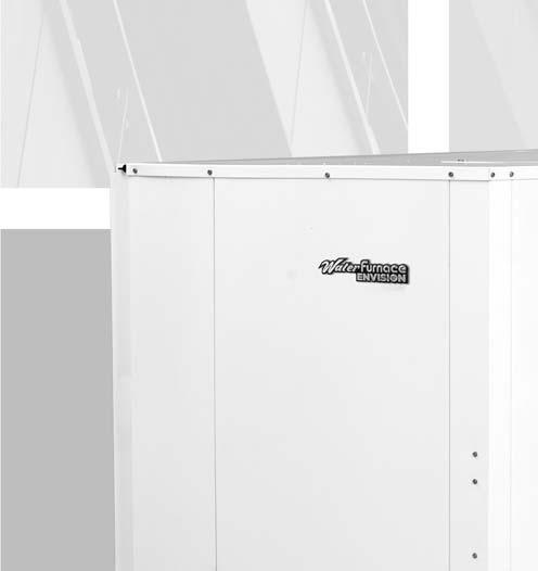
6 The Envision Series Nearly 25 years ago WaterFurnace led the way by designing and manufacturing watersource heat pumps for use in geothermal closed loop applications. In 2003 WaterFurnace developed the first R410A watersource heat pump product line. Now the Envision Series breaks ground again by providing the first 30 EER and 5 COP (ISO LHP) and the first 20 EER 6 COP (ISO WLHP) rated water-source heat pump on the market. Higher efficiency also means less heat rejected and ultimately shorter earth loops. WaterFurnace quality is well known and respected and is a result of quality engineering and manufacturing in the state of the art Fort Wayne, Indiana plant. The Envision Series provides: Highest efficiencies and lowest operating costs. Broadest R410A product line. Standard or extended range (geothermal) operation. Blower packages for low static applications. Oversized motors for high static applications. IAQ features. Quiet operation. Flexible control options. WaterFurnace Quality. Vertical Models NLV (7-25 tons) NXV (7-25 tons) Horizontal Models NLH (7-10 tons) NXH (7-10 tons) 7


 Adjustable blower sheaves")


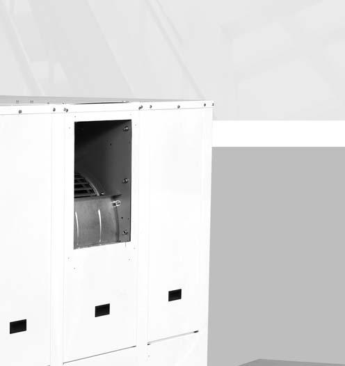
7 The Envision Series cont. Product Features: Vertical Cabinet Envision Vertical units are designed for high efficiency, maximum flexibility and primary servicing from the front and side. These cabinets are field convertible top and side discharge, and are available in two sizes. Powder coated and fully insulated heavy gauge steel cabinet Permanently-lubricated blower motor Easily removable access panels All-Aluminum oversized rifled tube lanced fin air coil (optional AlumiSeal TM coating) Adjustable blower sheaves Adjustable motor mounts Scroll compressors (2) Internally trapped condensate line Fully insulated refrigerant and water lines Microprocessor Controls: ABC - Standard UPC - Optional Environmentally friendly R-410A Refrigerant Flush mount water connections (back up wrench not needed) A true left and right return option is available. Left hand return Right hand return 8


 Scroll")


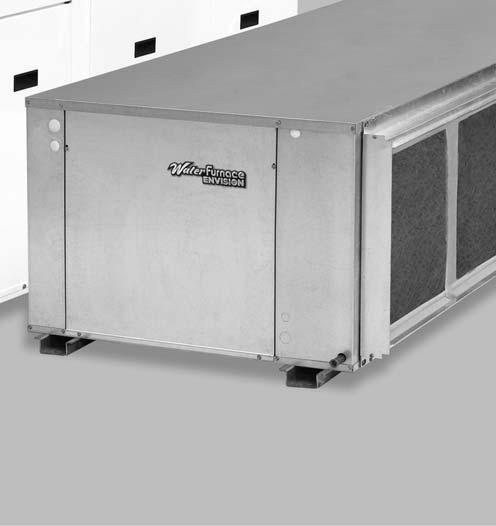
8 The Envision Series cont. Product Features: Horizontal Cabinet The Envision Horizontal units provide high efficiency, maximum flexibility, and primary servicing from the front. These units are available in one cabinet size. Flush mount water connections (backup wrench not required) Scroll Compressors (2) Bacterial resistant composite drain pan Dynamically balanced forward curved centrifugal blower Easy adjustment motor mount Reversing valve expansion valve Heavy duty galvanized steel cabinet w/factory mounted support rails Four blower deck options are available. Factory or field conversion option of end or side discharge using switchable access panels and a factory only option of true left or right return air coil. Right hand return with end discharge Left hand return with end discharge Right hand return with side discharge with side discharge 9
 water-source heat")

9 The Envision Series cont. High Efficiency Envision Series is the highest efficiency units available. Large oversized air coils, water to refrigerant heat exchangers and scroll compressors provide extremely efficient operation and produce the first 30 EER and 5 COP (ISO LHP) water-source heat pump on the market. This efficiency means the Envision Series requires less loop than any product on the market. This can mean significant savings on commercial projects. Quiet Operation All Envision Series product is AHRI 260 sound rated using third party sound testing. Room Noise Criteria Curves (NC Curve) may be calculated using data from the AHRI 260 ratings giving the engineer total flexibility in assuring a quiet environment. Please refer to our separate catalog WaterFurnace Sound Ratings and Performance Catalog concerning this standard and Envision sound performance data. AlpinePure Indoor Air Quality (IAQ) The Envision Series features several IAQ benefits. All units feature: Corrosion-free plastic or stainless steel double-sloped drain pan to eliminate standing water and prevent bacterial growth. Foil-faced fiber insulation in all air handler compartments to allow cleanability and inhibit bacteria growth. Optional non-fibrous closed cell insulation is also available for more sensitive applications. An optional low static high efficiency 2 in. [5.1 cm] MERV 13 filter is also available. Standard Features Large low rpm blower. Heavy gauge cabinet and rails on horizontals to hang for vibration isolation. Quiet scroll compressors in all models 2-dimension refrigerant piping vibration loops to isolate the compressor. All interior cabinet surfaces including the compressor compartment are insulated with 1/2 in. [12.7 mm] thick 1-1/2lb [681 g] density, surface coated, acoustic type glass fiber insulation. Super Quiet Option An optional SuperQuiet Sound Package is also available for a modest cost features: Multi-density laminate lined compressor blanket designed to completely surround the compressor on all six sides and suppress low frequency noise. Easy Maintenance and Service Advantages Removable compressor access panels. Separate Air handler and compressor section access panels permit service testing without bypass (Vertical only). Removable low voltage connector for easy thermostat wiring. Quick attach wiring harnesses are used throughout for fast servicing. High and low pressure refrigerant service ports. Internal drop out blowers (vertical) and access panel view of all blower motors (horizontal). Optional user interface for diagnostics and commissioning of FX controls. 10
 Some local building authority s interpretation of codes require more condensate overflow protection than standard microprocessor based")


10 The Envision Series cont. Secondary Drain Option (Special) Some local building authority s interpretation of codes require more condensate overflow protection than standard microprocessor based condensate sensors offer. In these areas a full secondary drain pan might be required causing both increased cost and unit service access issues. In many of these cases a secondary drain option can be added to the unit to pass this local interpretation of condensate drain redundancy. This option adds a second PVC drain connection to the drain pan at a higher level. This can be ordered as a special and is only availabe in plastic. Factory Quality All refrigerant brazing is performed in a nitrogen environment. Computer controlled deep vacuum and refrigerant charging system. All joints are leak detected for maximum leak rate of less than 1/4 oz. per year. Computer bar code equipped assembly line insures all components are correct. All units are computer run-tested with water to verify both function and performance. 11


11 Inside the Envision Series Refrigerant Envision products all feature zero ozone depletion and low global warming potential R-410A refrigerant. Water Connections Flush mount FPT water connection fittings allow one wrench leak-free connections and do not require a backup wrench. Cabinet All vertical units are all constructed of corrosion resistant galvanized sheet metal with optional white polyester powder coat paint rated for more than 1000 hours of salt spray. Large lift-out access panels provide access to the compressor section from four sides. Refrigerant circuit is designed to allow primary serviceability from the front. 1 horizontal and 2 vertical cabinets are provided for application flexibility. Air handler access panels allow servicing of the blower motor, blower, and drain pan. The blower motor and blower can be completely serviced or replaced without removal of the unit. Side or top discharge option is available on vertical units Flexible configurations include 4 blower deck options for horizontals and a true left and right return on both horizontal and vertical. Filter Rack A 2 in. [5.1 cm] disposable filter is standard. An optional 2 in. MERV 13 for high efficiency filtration is available. Drain Pan Bacteria resistant composite drain pan is sloped to promote complete drainage and will never rust or corrode. Complete drainage helps to inhibit bacterial or microbial growth. Vertical units feature an internally trapped condensate line using clear pvc hose for easy inspection and reduced installation cost. Stainless steel drain pans are available for 7-25 ton units. Compressors High efficiency R410A scroll compressors are used on every model. Scrolls provide both the highest efficiency available and great reliability. Electrical Box Unit controls feature quick connect wiring harnesses for easy servicing. Separate knockouts for LV, and two for power on two sides allow easy access to the control box. Large 75VA transformer assures adequate controls power for accessories. Thermostatic Expansion Valve All Envision models utilize a balanced port bi-directional thermostatic expansion valve (TXV) for refrigerant metering. This allows precise refrigerant flow in a wide range of entering water variation (20 to 120 F [-7 to 49 C]) found in geothermal systems. The TXV is located in the compressor compartment for easy access. 12


12 Inside the Envision Series cont. Water to Refrigerant Coaxial Heat Exchanger Coil Large oversized coaxial refrigerant to water heat exchangers provide unparalleled efficiency. The coaxes are designed for low pressure drop and low flow rates. All coaxes are pressure rated to 450 psi water side and 600 psi on the refrigerant side. Optional refrigerant and coaxial heat exchanger insulation is available to prevent condensation in low temperature loop operation. adjusted in the field without removal of the blower motor. This prevents the need for the service technician to realign the blower motor after service has been completed. All-Aluminum Air Coil All models in the Envision Commercial 7-25 Ton line are equipped with all-aluminum air coils. WaterFurnace is the first manufacturer to offer an all-aluminum roundtube-and-fin air coil in a packaged water source heat pump. These air coils are constructed of lanced fin and rifled tube aluminum that is not susceptible to formicary corrosion. For additional condensate runoff and meeting project specifications, an optional AlumiSeal e-coating is available. Service Connections and Serviceability Two Schrader service ports are provided for each circuit on every unit. The suction side and discharge side ports are for field charging and servicing access. All valves are 7/16 in. SAE connections. All water and electrical connections are made from the front of the unit. Unit is designed for front access serviceability. Blower Motor and Housing High efficiency low rpm galvanized belt drive blower reducing air noise. High static options are available in most models. Horizontal units can be field converted from end to side discharge. Vertical units can be field converted from top to side discharge with a few additional parts. 4-Way Reversing Valve Envision units feature a reliable all-brass pilot operated refrigerant reversing valve. The reversing valve operation is limited to change of mode by the control to enhance reliability. Air Handler Insulation Foil Faced air handler insulation provides cleanability to further enhance IAQ. Adjustable Motor Mount A heavy duty, 16 ga. steel adjustment motor mount is provided to allow easy service of the belt, sheaves, and blower motor. The angle of the plate can be easily 13
13 Controls - Aurora Base Control Aurora Base Control NOTE: Refer to the Aurora Base Control Application and Troubleshooting uide and the Instruction uide: Aurora Interface and Diagnostics (AID) Tool for additional information. Control Features Software ABC Standard Version 2.0 Single or Dual Capacity Compressors Either single or dual capacity compressors can be operated. Variable Speed ECM Blower Motor Option (If Applicable) A Variable Speed ECM blower motor can be driven directly using the onboard PWM output. Four blower speeds are available based upon the, Y1, Y2, and W input signals to the board. The blower speeds can be changed either by the ECM manual configurations mode method or by using the Aurora AID Tool directly. All four blower speeds can be set to the same speed if desired. 5-Speed ECM Blower Motor Option (If Applicable) A 5-Speed ECM blower motor will be driven directly using the thermostat connections. Any of the, Y1, or Y2/W signals can drive any of the 5 available pre-programmed blower speeds on the motor. All 5 Series "" vintage units will be wired this way at the factory. Other Control Features Random start at power up Anti-short cycle protection High and low pressure cutouts Loss of charge Water coil freeze detection Air coil freeze detection Over/under voltage protection Condensate overflow sensor Load shed Dehumidification (where applicable) Emergency shutdown Hot gas reheat operation (where applicable) Diagnostic LED Test mode push button switch Two auxiliary electric heat outputs Alarm output Accessory output with N.O. and N.C. Modbus communication (master) Modbus communication (slave) Field Selectable Options via Hardware DIP Switch (SW1) Test/Configuration Button (See SW1 Operation Table) Test Mode The control is placed in the test mode by holding the push button switch SW1 for 2-5 seconds. In test mode most of the control timings will be shortened by a factor of sixteen (16). LED3 (green) will flash at 1 second on and 1 second off. Additionally, when entering test mode LED1 (red) will flash the last lockout one time. Test mode will automatically time out after 30 minutes. Test mode can be exited by pressing and holding the SW1 button for 2 to 5 seconds or by cycling the power. NOTE: Test mode will automatically be exited after 30 minutes. ECM Configuration Mode (If Applicable) The control is placed in the ECM configuration mode by holding the pushbutton switch SW1 for 5 to 10 seconds, the high, low, and ECM speeds can be selected by following the LED display lights. LED2 (yellow) will fast flash when entering the ECM configuration. When setting speed LED3 (green) will be continuously lit, for low speed LED1 (red) will be continuously lit, and for high speed both LED3 (green) and LED1 (red) will be continuously lit. During the ECM configuration mode LED2 (yellow) will flash each of the 12 possible blower speeds 3 times. When the desired speed is flashed press SW1, LED2 will fast flash until SW1 is released. speed has now been selected. Next select low speed, and high speed blower selections following the same process above. After third selection has been made, the control will exit the ECM configuration mode. Aux fan speed will remain at default or current setting and requires the AID Tool for adjustment. Reset Configuration Mode The control is placed in reset configuration mode by holding the push button switch SW1 for 50 to 60 seconds. This will reset all configuration settings and the EEPROM back to the factory default settings. LED3 (green) will turn off when entering reset configuration mode. Once LED3 (green) turns off, release SW1 and the control will reset. DIP Switch (SW2) SW2-1 FP1 Selection Low water coil temperature limit setting for freeze detection. On = 30 F; Off = 15 F. SW2-2 FP2 Selection On = 30 F; Off = N/A SW2-3 RV O/B - thermostat type. Heat pump thermostats with O output in cooling or B output in Heating can be selected. On = O; Off = B. SW2-4 Access Relay Operation (P2) and 2-5 Access Relay Operation SW2-4 SW2-5 Cycle with Blower ON ON Cycle with Compressor OFF OFF Water Valve Slow Opening ON OFF Cycle with Comm. T-stat Hum Cmd OFF ON 14
14 Controls - Aurora Base Control cont. Cycle with Blower - The accessory relay will cycle with the blower output. Cycle with Compressor r - The accessory relay will cycle with the compressor output. Water Valve Slow Opening - The accessory relay will cycle and delay both the blower and compressor output for 90 seconds. SW2-6 CC Operation selection of single or dual capacity compressor. On = Single Stage; Off = Dual Capacity SW2-7 Lockout and Alarm Outputs (P2) selection of a continuous or pulsed output for both the LO and ALM Outputs. On = Continuous; Off = Pulsed SW2-8 Future Use Alarm Jumper Clip Selection From the factory, ALM is connected to 24 VAC via JW2. By cutting JW2, ALM becomes a dry contact connected to AL. ECM Blower Speeds The blower speeds can be changed either by using the ECM manual configurations mode method or by using the Aurora AID Tool directly (see Instruction uide: Aurora Interface and Diagnostics (AID) Tool topic). Field Selectable Options via Software (Selectable via the Aurora AID Tool) ECM Blower Speeds An ECM blower motor can be driven directly using the onboard PWM output. Four blower speeds are available, based upon the, Y1 (low), Y2 (high), and Aux input signals to the board. The blower speeds can be changed either by the ECM manual configurations mode method (see ECM Configuration Mode topic) or by using the Aurora AID Tool directly. All four blower speeds can be set to the same speed if desired. Aux blower speed will remain at default or current setting and requires the AID Tool for adjustment. Safety Features The following safety features are provided to protect the compressor, heat exchangers, wiring and other components from damage caused by operation outside of design conditions. Fuse a 3 amp automotive type plug-in fuse provides protection against short circuit or overload conditions. Anti-Short Cycle Protection 4 minute anti-short cycle protection for the compressor. Random Start 5 to 80 second random start upon power up. Fault Retry in the fault condition, the control will stage off the outputs and then try again to satisfy the thermostat Y input call. Once the thermostat input calls are satisfied, the control will continue on as if no fault occurred. If 3 consecutive faults occur without satisfying the thermostat Y input call, then the control will go to Lockout mode. Lockout when locked out, the blower will operate continuously in speed, and PSC blower motor output will remain on. The Alarm output (ALM) and Lockout output (L) will be turned on. The fault type identification display LED1 (Red) shall flash the fault code. To reset lockout conditions with SW2-8 On, thermostat inputs Y1, Y2, and W must be removed for at least 3 seconds. To reset lockout conditions with SW2-8 Off, thermostat inputs Y1, Y2, W, and DH must be removed for at least 3 seconds. Lockout may also be reset by turning power off for at least 30 seconds or by enabling the emergency shutdown input for at least 3 seconds. Lockout With Emergency Heat - if the control is locked out in the heating mode, and a Y2 or W input is received, the control will operate in the emergency heat mode while the compressor is locked out. The first emergency heat output will be energized 10 seconds after the W input is received, and the blower will shift to high speed. If the control remains locked out, and the W input is present, additional stage of emergency heat will stage on after 2 minutes. When the W input is removed, all of the emergency heat outputs will turn off, and the ECM blower will shift to speed and PSC blower motor output will remain on. High Pressure fault is recognized when the Normally Closed High Pressure Switch, P4-9/10 opens, no matter how momentarily. The High Pressure Switch is electrically in series with the Compressor Contactor and serves as a hardwired limit switch if an overpressure condition should occur. Low Pressure - fault is recognized when the Normally Closed Low Pressure Switch, P4-7/8 is continuously open for 30 seconds. Closure of the LPS any time during the 30 second recognition time restarts the 30 second continuous open requirement. A continuously open LPS shall not be recognized during the 2 minute startup bypass time. Loss of Charge fault is recognized when the Normally Closed Low Pressure Switch, P4-7/8 is open prior to the compressor starting. Condensate Overflow - fault is recognized when the impedance between this line and 24 VAC common or chassis ground drops below 100K ohms for 30 seconds continuously. Freeze Detection (Coax) - set points shall be either 30 F or 15 F. When the thermistor temperature drops below the selected set point, the control shall begin counting down the 30 seconds delay. If the thermistor value rises above the selected set point, then the count should reset. The resistance value must remain below the selected set point for the entire length of the appropriate delay to be recognized as a fault. This fault will be ignored for the initial 2 minutes of the compressor run time. Freeze Detection (Air Coil) - uses the FP2 input to protect against ice formation on the air coil. The FP2 input will operate exactly like FP1 except that the set point is 30 degrees and is not field adjustable. 15
15 Controls - Aurora Base Control cont. Over/Under Voltage Shutdown - An over/under voltage condition exists when the control voltage is outside the range of 18 VAC to 30 VAC. If the over/under voltage shutdown lasts for 15 minutes, the lockout and alarm relay will be energized. Over/under voltage shutdown is selfresetting in that if the voltage comes back within range of 18 VAC to 30 VAC for at least 0.5 seconds, then normal operation is restored. Operation Description Power Up - The unit will not operate until all the inputs and safety controls are checked for normal conditions. The unit has a 5 to 80 second random start delay at power up. Then the compressor has a 4 minute anti-short cycle delay after the random start delay. Standby In standby mode, Y1, Y2, W, DH, and are not active. Input O may be active. The blower and compressor will be off. Heating Operation Single Compressor Heating, 2nd Stage (Y1, Y2) The compressor will be staged to full capacity 20 seconds after Y2 input is received. The ECM blower will shift to high speed seconds after the Y2 input is received. Dual Compressor Heating, 2nd Stage (Y1, Y2) In dual compressor operation, two ABC boards used in 24 VAC operation, there will be a Y2 call to the Y1 input on the second ABC. The compressor will stage to full capacity 30 seconds after Y1 input is received to the second board. Single Compressor Heating, 3rd Stage (Y1, Y2, W) The hot water pump is de-energized and the first stage of electric heat is energized 10 seconds after the W command is received. If the demand continues the second stage of electric heat will be energized after 5 minutes. Dual Compressor Heating, 3rd Stage (Y1, Y2, W) - The first stage of electric heat is energized 10 seconds after the W command is received. If the demand continues the second stage of electric heat will be energized after 5 minutes Emergency Heat (W) - The blower will be started on speed, 10 seconds later the first stage of electric heat will be turned on. 5 seconds after the first stage of electric heat is energized the blower will shift to Aux speed. If the emergency heat demand is not satisfied after 2 minutes the second electric heat stage will be energized. Cooling Operation In all cooling operations, the reversing valve directly tracks the O input. Thus, anytime the O input is present, the reversing valve will be energized. Single Compressor Cooling, 2nd Stage (Y1, Y2, 0) The compressor will be staged to full capacity 20 seconds after Y2 input was received. The ECM blower will shift to high speed 15 seconds after the Y2 input was received. Dual Compressor Cooling, 2nd Stage (Y1, Y2, O) In dual compressor operation, two ABC boards used in 24 VAC operation, there will be a Y2 call to the Y1 input on the second ABC. The compressor will stage to full capacity 30 seconds after Y1 input is received to the second board. Blower () - The blower will start immediately upon receiving a thermostat command. If there are no other commands from the thermostat the ECM will run on speed until the command is removed. Regardless of blower input () from the thermostat, the blower will remain on for 30 seconds at the end of each heating, cooling, and emergency heat cycle. Dehumidification (Y1, O, DH or Y1, Y2, O, DH) - When a DH command is received from the thermostat during a compressor call for cooling the ECM blower speed will be reduced by 15% to increase dehumidification. Emergency Shutdown - Four (4) seconds after a valid ES input, P2-7 is present, all control outputs will be turned off and remain off until the emergency shutdown input is no longer present. The first time that the compressor is started after the control exits the emergency shutdown mode, there will be an anti-short cycle delay followed by a random start delay. Input must be tied to common to activate. Continuous Blower Operation - The blower output will be energized any time the control has a input present, unless the control has an emergency shutdown input present. The blower output will be turned off when input is removed. Load Shed - The LS input disables all outputs with the exception of the blower output. When the LS input has been cleared, the anti-short cycle timer and random start timer will be initiated. Input must be tied to common to activate. Blower () - The blower will start immediately upon receiving a thermostat command. If there are no other commands from the thermostat the ECM will run on speed until the command is removed. Regardless of blower input () from the thermostat, the blower will remain on for 30 seconds at the end of each heating cycle. 16

 Flash Code 3 (Future Use) Flash Code 4 Load Shed Flash Code 5 ESD Flash Code 6 (Future Use) Flash Code 7 Configuration LED (LED2, Yellow) Description of Operation No Software Overwritten DIP")

16 Controls - Aurora Base Control cont. Aurora Base Control LED Displays These three LEDs display the status, configuration, and fault codes for the control. These can also be read in plain English via the Aurora AID Tool. Status LED (LED3, reen) Description of Operation Fault LED, reen Normal Mode ON Control is Non-functional OFF Test Mode Slow Flash Lockout Active Fast Flash Dehumidification Mode Flash Code 2 (Future Use) Flash Code 3 (Future Use) Flash Code 4 Load Shed Flash Code 5 ESD Flash Code 6 (Future Use) Flash Code 7 Configuration LED (LED2, Yellow) Description of Operation No Software Overwritten DIP Switch was Overwritten ECM Configuration Mode Fault LED (LED1, Red) Red Fault LED Configuration LED, Yellow Flashing ECM Setting Slow Flash Fast Flash LED Flash Code* Lockout Reset/ Remove Normal - No Faults OFF Fault - Input 1 No Auto Fault - High Pressure 2 Yes Hard or Soft Fault - Low Pressure 3 Yes Hard or Soft Fault - Freeze Detection FP2 4 Yes Hard or Soft Fault - Freeze Detection FP1 5 Yes Hard or Soft Fault - Condensate Overflow 7 Yes Hard or Soft Fault - Over/Under Voltage 8 No Auto Fault - FP1 & FP2 Sensor Error 11 Yes Hard or Soft NOTE: All codes >11 use long flash for tens digit and short flash for the ones digit. 20, 30, 40, 50, etc. are skipped. ABC Basic Faults Aurora Interface and Diagnostics (AID) Tool The Aurora Interface and Diagnostics (AID) Tool is a device that is a member of the Aurora network. The AID Tool is used to troubleshoot equipment which uses the Aurora control via Modbus RTU communication. The AID Tool provides diagnostics, fault management, ECM setup, and system configuration capabilities to the Aurora family of controls. An AID Tool is recommended, although not required, for ECM airflow settings. The AID Tool simply plugs into the exterior of the cabinet in the AID Tool port. ABC Control Board Layout 6.25 in. CC2 CC2 F CC Y1 HP HP LP LP FP2 FP2 FP1 FP1 REV REV LO HI CC CC F F R Factory P5 Factory JW2 - Alarm P2 P4 PWM CFM C ECM PWM P13 SW1 Test RV K1 CC K2 CC Hi K3 Fan K4 Alarm K5 Acc K6 Field Connections Off LED 1 FP1 15 o F/30 o F R FP2 15 o F/30 o F Fault RV B/O ACC Dip 1 ACC Dip 2 LED 3 CC Dual/Single L Pulse/Continuous Status Reheat/Normal P9 LO P1 P11 Factory Use 5.0 in. Aurora TM Base Control Factory Fan Connection R C O/B Field Connections SW2 On 1 LED 2 2 Y 3 Config Y1 Y2 W DH Com1 Com2 3A-Fuse Factory P6 P3 RS485 Exp LED 5 P7 RS 485 P8 LED 4 RS485 NET EH1 EH2 C EH1 C CO N/A (+) (-) R C (+) (-) R C C C C 5.75 in. ES LS ALM AL ACC c ACC no ACC nc LO R C O/B Y1 Y2 W DH R R 5.5 in. 17
 is designed to allow water source heat pumps to be integrated into Building Automation Systems (BAS) with ease.")


17 Controls - UPC DDC Control (optional) Aurora UPC Controller ZS Series Sensors The Aurora Unitary Protocol Converter (UPC) is designed to add-on to any Aurora based heat pump control. The Aurora Unitary Protocol Convertor (UPC) is designed to allow water source heat pumps to be integrated into Building Automation Systems (BAS) with ease. The Aurora UPC is an integrated solution and communicates directly with the Aurora Heat Pump Controls and allows access/control of a variety of internal Aurora heat pump operations such as sensors, relay operation, faults and other information. In turn, the UPC then converts internal Aurora Modbus protocol to BACnet MS/TP, LON, or N2 protocols and communicates to the BAS system. This provides the great benefit of complete control integration and a myriad of information available to the BAS from the heat pump control. Plus it also allows individual unit configuration such as ECM fan speeds or freeze protection setting directly over the BAS without the need for access to the actual heat pump. The Aurora UPC is programmed using the powerful Eikon object oriented. The Aurora UPC is implemented with the Aurora Base Controller (ABC) heat pump control into our latest water source heat pumps. This will allow for a BAS to integrate and communicate to the heat pump thru a choice of 3 different communication protocols. The Aurora UPC has the ability to communicate BACnet MS/TP, N2 open, or LonWorks (requires LON Plugin card). This flexibility is possible due to the onboard dipswitches which allow for the desired protocol and baud rate to be selected in the field. All zone temperatures and zone sensors are connected to the UPC on an RNet bus, simplifying hook up at the unit. RNet sensors can include a combination of zone temperature and humidity, CO2, and VOC sensors. The UPC includes built-in support for a custom configurable keypad/display unit - BACview6 (4-line by 40 character per line display) or BACview5 (2-line by 16 character per line display). Up to 2 Keypad/display units can be mounted remotely for configuration and troubleshooting. There are an extensive number of points that the UPC has available over the network for integration into the BAS. Control programmers need to carefully determine which points they want to add into the BAS database. A list of the BACnet points, N2 points, and LON SNVTs are available along with their individual point descriptions by contacting the Commercial Solutions roup at


 to be connected for space temperature")


18 Controls - UPC DDC Control (optional) cont. N2 Modbus BAS BACnet LonWorks Rnet Aurora UPC Features Rugged enclosure made of E C2950 Cycoloy plastic Built-in surge transient protection circuitry Operating range of -20 to 140 F; 10 to 95% relative humidity, non-condensing Onboard CR123A battery has a life of 10 years with 720 hours of cumulative power outage Multi-Protocol field selectable communication port that supports: EIA-485 BACnet 9600, 19.2k, 38.4k, 76.8k baud Metasys N2 Open LonWorks TP/FT-10 (Requires optional LON plug-in communication card) Status of all unit operating conditions and fault lockouts Visual LED s for status of power, network communication, processor operation, and errors Provides gateway into Aurora heat pump controls for unsurpassed control flexibility Network point for commanding unit into load shed Network point for commanding unit into emergency shutdown Network points to assist in fan speed selection Network points for freeze protection settings Heating and cooling control from a remotely located zone sensor Rnet communication port which allows for multiple Rnet zone sensors (5) to be connected for space temperature averaging if desired. Local laptop or BACview connection for field service FCC, UL and CE listed. BTL Certification is pending Aurora UPC Optional Features BACview handheld display, needed for field configuration of fan speeds, set points, etc. AID Tool for Aurora ABC configuration and troubleshooting. Aurora Advanced Control adds the Aurora AXB expansion board and provides added I/O and standard features Optional Sensor Kits (requires Aurora Advanced Control with AXB - Future Availability on Select Models/Configurations) Refrigeration Monitoring provides Suction and discharge pressure, Suction, liquid line temps and superheat and subcooling. Performance Monitoring provides entering and leaving loop water temperatures, loop flow rate as well as heat of extraction or rejection rate into the loop. Energy Monitoring provides real-time power measurement (Watt) of compressor, fan, auxiliary heat and zone pump. raphics packages available in the future 19
. Port 1b is used for the LonWorks plugin.")
19 Controls - UPC DDC Control (optional) cont. Port 1a is used to communicate to the Building Automation System (BAS). This port s settings are configured through the onboard dip switches. Port 2 is used to communicate to the Aurora Base Controller (ABC). Port 1b is used for the LonWorks plugin. 24Vac Dip switches for configuring the communication port protocol and baud rate for the BAS port. Rnet port is used for communicating zone sensors. Mac address is set by 2 rotary dials. BACview or local laptop connection. Aurora Touch Interface Utilizing a touch-screen interface, the UPC provides a technician the ability to configure and diagnose equipment at the unit or from any room sensor for added accessibility and simpler troubleshooting. The technician will have full access to equipment status, parameter values, temperature, and humidity sensing as well as access to alarm and trend history. With website-like navigation, the Aurora Touch Interface is easy to use and provides important insight into the system so your building can operate as efficiently as possible. 20
20 Controls - UPC DDC Control (optional) cont. 1. Leaving Air Temperature (LAT) Sensor This 10 kohm NTC sensor is factory installed on all UPC equipped heat pumps. It typically is attached to wiring inside the blower cabinet on the suction side of the blower. This sensor is attached on ABC FP2 pins available as LAT AU Compressor Proving Sensors This optional factory installed current sensor is connected to confirm compressor operation via the power wires. The sensor is attached at ABC Y1 and available at point BV Valve End Switch This optional input is setup for a field installed flow valve end switch. This end switch input is attached at ABC Y2 and available at point BV Fan Proving Sensors This optional factory installed current sensor is connected to confirm fan operation via the power wires. The sensor is attached at ABC and available at point BV Occupancy Sensor - This standard feature includes a field installed and wired room sensor with occupancy sensor typically found in DDC systems. The RNet room sensors can be found thru your commercial representative. The occupancy Sensors are attached at ABC 0 and can be found at point BV Dirty Filter Switch This optional field installed switch is connected to confirm dirty filter operation. The dirty filter switch can be found thru your commercial representative. The sensor is attached at ABC W and available at point BV Fault, Configuration, and Status Codes The codes can be visible to the BAS if desired Aurora Base Fault Codes (ABC Only) Fault LED (LED1, Red) Red Fault LED LED Flash Code* Lockout Reset/ Remove Normal - No Faults OFF Fault - Input 1 No Auto Fault - High Pressure 2 Yes Hard or Soft Fault - Low Pressure 3 Yes Hard or Soft Fault - Freeze Detection FP2 4 Yes Hard or Soft Fault - Freeze Detection FP1 5 Yes Hard or Soft Fault - Condensate Overflow 7 Yes Hard or Soft Fault - Over/Under Voltage 8 No Auto Fault - FP1 & FP2 Sensor Error 11 Yes Hard or Soft NOTE: All codes >11 use long flash for tens digit and short flash for the ones digit. 20, 30, 40, 50, etc. are skipped. ABC Basic Faults Aurora Advanced Fault Codes (ABC + AXB Expansion Board) Fault LED (LED1, Red) ABC Basic Faults Red Fault LED LED Flash Code * Lockout Reset/ Remove Fault Condition Summary Normal - No Faults Off - Fault-Input 1 No Auto Tstat input error. Autoreset upon condition removal. Fault-High Pressure 2 Yes Hard or Soft HP switch has tripped (>600 psi) Fault-Low Pressure 3 Yes Hard or Soft Low Pressure Switch has tripped (<40 psi for 30 continuous sec.) Fault-Freeze Detection FP2 4 Yes Hard or Soft Freeze protection sensor has tripped (<15 or 30 degf for 30 continuous sec.) Fault-Freeze Detection FP1 5 Yes Hard or Soft Freeze protection sensor has tripped (<15 or 30 degf for 30 continuous sec.) Fault-Condensate Overflow 7 Yes Hard or Soft Condensate switch has shown continuity for 30 continuous sec. Fault-Over/Under Voltage 8 No Auto Instantaneous voltage is out of range. **Controls shut down until resolved. Fault-FP1 & 2 Snsr Error 11 Yes Hard or Soft If FP1 or 2 Sensor Error Fault-Compressor Monitor 10 Yes Hard or Soft Open Crkt, Run, Start or welded cont Non-CriticAXBSnsrErr 13 No Auto Any Other Sensor Error CriticAXBSnsrErr 14 Yes Hard or Soft Sensor Error for EEV or HW Alert-HotWtr 15 No Auto HW over limit or logic lockout. HW pump deactivated. Fault-VarSpdPump 16 No Auto Alert is read from PWM feedback. Not Used 17 No Auto IZ2 Com Fault. Autoreset upon condition removal. Non-CritComErr 18 No Auto Any non-critical com error Fault-CritComErr 19 No Auto Any critical com error. Auto reset upon condition removal Alarm - Low Loop Pressure 21 No Auto Loop pressure is below 3 psi for more than 3 minutes Alarm - Home Automation 1 23 No Auto Closed contact input is present on Dig 2 input - Text is configurable Alarm - Home Automation 2 24 No Auto Closed contact input is present on Dig 3 input - Text is configurable NOTES: *All codes >11 use long flash for tens digit and short flash for the ones digit. 20, 30, 40, 50 etc. are skipped! Alert is a noncritical sensor or function that has failed. Normal operation of the heat pump is maintained but service is desired at some point. ABC & AXB Advanced Faults 21
21 Controls - UPC DDC Control (optional) cont. Aurora Base or Advanced Control Configuration and Status Codes Status LED (LED3, reen) Description of Operation Fault LED, reen Normal Mode ON Control is Non-functional OFF Test Mode Slow Flash Lockout Active Fast Flash Dehumidification Mode Flash Code 2 Load Shed Flash Code 5 Emergency Shutdown Flash Code 6 On Peak Mode Flash Code 7 (Future Use) Flash Code 8 (Future Use) Flach Code 9 Configuration LED (LED2, Yellow) Description of Operation No Software Overwritten DIP Switch Overwritten ECM Configuration Mode Reset Configuration Mode Configuration LED, Yellow ECM Setting Slow Flash Fast Flash OFF 9. Alarm Relay The Alarm relay (ALM) is factory connected to 24 VAC via jumper JW2. By cutting JW2, ABC ALM becomes a dry contact connected to ABC AL. The Relay is field switchable between Factory setting as an Alarm output or available for other uses. 10. Accessory Relay1 A configurable, accessory relay on the ABC is provided that can be cycled with the compressor, blower, or the Dehumidifier (DH) input. A third (factory) setting cycles the relay with the compressor but delays the compressor and blower output for 90 sec. Source pump or slow opening solenoid valves in well systems or variable speed primary pumping systems would be a prime use of this feature. Access Relay Operation SW2-4 SW2-5 Cycle with Blower ON ON Cycle with Compressor OFF OFF Water Valve Slow Opening ON OFF Cycle with Comm. T-stat Hum Cmd OFF ON 11. Electric Heat EH1 A digital 24VDC output is provided for electric heat powering. UPC s Default programming has EH1 set for AUX/ELEC Heat operation and will be controlled using the UPC s internal P.I.D. logic. However it can be changed by the BAS to be network controlled. 12. Electric Heat EH2 A digital VDC output is provided for field options converted from the original EH2 output. Default UPC program has the EH2 output set for Network Control but can be changed by the BAS to be controlled by the UPC s internal P.I.D. logic. 22
22 Controls - UPC DDC Control (optional) cont. Aurora Advanced Control Configuration and Options (Future Availability on Select Models/Configurations) 1. Accessory Relay2 A second, configurable, accessory relay on the AXB is provided that can be cycled with the compressor 1 or 2, blower, or the Dehumidifier (DH) input. This is to complement the Accessory 1 Relay on the ABC board. Position DIP 4 DIP 5 Description 1 ON ON Cycles with Fan or ECM (or ) 2 OFF ON Cycles with CC1 first stage of compressor or compressor spd ON OFF Cycles with CC2 second stage of compressor or compressor spd OFF OFF Cycles with DH input from ABC board 2. Analog Out A standard 0-10VDC analog output is provided. This output can be used to drive modulating dampers etc. 3. Variable Speed Pump or Modulating Water Valve - This input and output are provided to drive and monitor a variable speed pump. The VS pump output is a PWM signal to drive the variable speed pump. The minimum and maximum level are set using the AID Tool. 75% and 100% are the default settings respectively. The VS data input allows a separate PWM signal to return from the pump giving fault and performance information. Fault received from the variable speed pump will be displayed as E16. Modulating Water Valve - This Variable speed PWM output is provided to optionally drive a modulating water valve. Through advanced design a 0-10VDC valve can be driven directly from the VS pump output. The minimum and maximum level are set in the same way as the VS pump using the AID Tool. 75% and 100% are the default settings respectively. 4. Loop Pump Slaving - This input and output are provided so that two units can be slaved together with a common flow center. When either unit has a call for loop pump, both unit s loop pump relays and variable speed pumps are energized. The flow center then can simply be wired to either unit. The output from one unit should be routed to the input of the other. If daisy chained up to 16 heat pumps can be wired and slaved together in this fashion. 23
23 Controls - UPC DDC Control (optional) cont. Aurora Advanced Control Optional Sensor Kits (Future Availability on Select Models/Configurations) 1. Energy Monitoring (Standard Sensor Kit on Advanced models) - The Energy Monitoring Kit includes two current transducers (blower and electric heat) added to the existing two compressor sensors so that the complete power usage of the heat pump can be measured. The BACview Tool provides configuration detail for the type of blower motor and a line voltage calibration procedure to improve the accuracy. This real time power usage information can be displayed on the AID Tool and is available thru network points when using BACnet or N2 Open. Compressor Current 1 Compressor Current 2 Fan Current Aux Heat Current Pump Selection Voltage Compressor Watts Fan Watts Aux Heat Watts Pump Watts (VS Only) 3. Performance Monitoring (optional sensor kit) - The optional Performance Monitoring Kit includes: three temperature sensors, entering and leaving water, leaving air temperature and a water flow rate sensor. With this kit, heat of extraction and rejection will be calculated. This requires configuration using the BACview Tool for selection of water or antifreeze. Leaving Air Temperature (supply) Alt Leaving Air Temperature (Supply) Entering Water Temperature Leaving Water Temperature Water Flow Meter Entering Air Temperature (from zone sensor) Brine Selection (water/antifreeze) Heat of Extraction/Rejection 2. Refrigerant Monitoring (optional sensor kit) - The optional Refrigerant Monitoring Kit includes two pressure transducers, and three temperature sensors, heating liquid line, suction temperature and existing cooling liquid line (FP1). These sensors allow the measurement of discharge and suction pressures, suction and liquid line temperatures as well as superheat and subcooling. This information can be displayed on the BACview Tool, or the network when using BACnet and N2. Htg Liquid Line Clg Liquid Line Discharge pressure Suction Pressure Discharge Saturated Temp Suction Saturated Temperature Superheat SubCooling 24

24 Controls - UPC DDC Control (optional) cont. ZS Series RNet Sensor Overview The ZS Series line of intelligent zone sensors provides the function and flexibility you need to manage the conditions important to the comfort and productivity of the zone occupants. The ZS sensors are available in a variety of zone sensing combinations to address your application needs. These combinations include temperature, relative humidity, and indoor air quality (carbon dioxide or VOCs (Volatile Organic Compounds)). They are built to be flexible allowing for easy customization of what the user/ technician sees. Designed to work with the Aurora UPC controllers the ZS sensor line includes the ZS Base, ZS Plus, ZS Pro and ZS Pro-F. The UPC uses a proprietary communication called Rnet to receive the space temperature from the zone sensor. This is done using (2) 18 AW twisted pair unshielded cables for a total of 4 wires connected to the Rnet port. The sensor gets its power from the UPC controller and connecting multiple sensors to one UPC will allow for space temperature averaging. The UPC can support one ZS Pro or ZS Pro F with up to four ZS standard sensors wired to the Rnet port on the UPC for a total of 5 zone sensors. The sensors use a precise 10k ohm thermistor with less than 0.18 F drift over a ten year span, this allows for less maintenance or re-calibration after installation. The sensors also have a hidden communication port for connecting a BACview or local laptop that provides access to the equipment for commissioning and maintenance. The table below shows the features of each of the four sensors that are currently available. ZS Base ZS Plus ZS Pro ZS Pro-F Features ZS Base ZS Plus ZS Pro ZS Pro-F Temp, CO 2, Humidity, and VOC Options Neutral Color Addressable/supports daisy chaining Hidden communication port Mounts on a standard 2 by 4 electrical box Occupancy Status indicator LED Push button occupancy override Setpoint adjust Large, easy to read LCD Alarm indicator F to C conversion button Options Part Number Part Number Part Number Part Number Temperature Only ZSU ZSUPL ZSUP ZSUPF Temp with CO 2 ZSU-C ZSUPL-C ZSUP-C ZSUPF-C Temp with Humidity ZSU-H ZSUPL-H ZSUP-H ZSUPF-H Temp with Humidity, CO 2 ZSU-HC ZSUPL-HC ZSUP-HC ZSUPF-HC Temp, Humidity, VOC ZSU-HV ZSUPL-HV ZSUP-HV ZSUPF-HV Temp with VOC ZSU-V ZSUPL-V ZSUP-V ZSUPF-V 25
 Temperature (on Humidity models) 50 F to 104 F (10 C to 40 C) ±0.5 F (0.3 C) Humidity 10% to 90% ±1.")
25 Controls - UPC DDC Control (optional) cont. RNet Sensor Physical and Electrical Data Sensing Element Range Accuracy Temperature (on non-humidity models) -4 to 122 F (-20 C to 50 C) ±0.35 F (0.2 C) Temperature (on Humidity models) 50 F to 104 F (10 C to 40 C) ±0.5 F (0.3 C) Humidity 10% to 90% ±1.8% typical CO2 400 to 1250 PPM 1250 to 2000 PPM ±30PPM or +/-3% of reading (greater of two) ±5% of reading plus 30 PPM VOC 0 to 2,000 PPM ±100 PPM Power Requirements Sensor Type Power Required Temperature Only All Models 12 8 ma Temperature with Humidity All Models ma (idle) to 190 ma (CO2 measurement cycle) Temp with VOC, or Temp/VOC/Humidity All Models ma Temp with CO2, or Temp/ CO2/Humidity All Models ma (idle) to 190 ma (CO2 measurement cycle) Power Supply Communication Local Access Port Environmental Operating Range Mounting Dimensions A controller supplies the Rnet sensor network with ma. Additional power may be required for your application. See sensor ZS Installation uide 115 kbps Rnet connection between sensor(s) and controller 15 sensors max per Rnet network; 5 sensors max per control program For connecting a laptop computer to the local equipment for maintenance and commissioning 32 to 122 F (0-50 C), 10% to 90% relative humidity, non-condensing Standard 4 x 2 electrical box using provided 6/32 x 1/2 mounting screws 26
26 Hot as Reheat/Hot as Bypass Hot as Reheat Description The refrigerant flows in normal heat pump path in heating and cooling mode. During the Reheat mode, the operation begins with superheated vapor leaving the compressor going through the reheat valve to the reheat air coil. In the reheat coil the high temperature high pressure gas reheats the air exiting the unit to near neutral. Next, the refrigerant exits the reheat coil and passes through a check valve, which is used to prevent refrigerant flow into the reheat coil during normal heating and cooling operation. The refrigerant passes through the check valve and is then diverted to the coaxial heat exchanger by the four way reversing valve. The hot gas enters the coaxial heat exchanger which will condense the gas to a high pressure liquid due to heat being rejected to the loop fluid. The high pressure liquid leaves the coax and enters the inlet of the TXV. After passing through the TXV the low pressure mixture of liquid/vapor refrigerant expands in the air coil evaporating into a low pressure low temperature gas and moves back through the reversing valve and into the compressor suction. The cycle then starts again by compressing the low pressure low temperature gas into a superheated vapor. A small copper bleed line is located on the reheat/reclaim valve to allow refrigerant that has migrated to the reheat coil to escape. Hot as Bypass Description The hot gas bypass (HB) option is designed to limit the minimum evaporating pressure in the cooling mode to prevent the air coil from icing. The HB valve senses pressure at the outlet of the evaporator by an external equalizer. If the evaporator pressure decreases to 115 psig the HB valve will begin to open and bypass hot discharge gas into the inlet of the evaporator. The valve will continue to open as needed until it reaches its maximum capacity. Upon a rise of suction pressure, the valve will begin to close back off and normal cooling operation will resume. 27
27 Hot as Reheat/Hot as Bypass cont. Hot as Reheat Dehumidification Overview Dehumidification - The Need for Reheat With tighter construction and more and more ventilation air being introduced into buildings, there is more need now than ever for proper humidity control. Ensuring dehumidification can provide consistent employee comfort, a reduction in mold liability, a reduction in cooling costs. Reduced humidity also provides an improvement in indoor air quality (IAQ) thru lower humidity levels which can reduce allergen levels, inhibit mold and bacterial growth, and provide an improved computer environment. ASHRAE 90.1 speaks of an acceptable humidity range in all commercial buildings. Typical Reheat Applications Reheat can be used wherever moisture is a problem. Schools, high latent auditorium and theaters, makeup air units*, and computer rooms are typical applications. Although reheat equipped water source heat pumps (wshp s) can condition limited amounts of outdoor air, the percentage of this outdoor air should never exceed 50% of the return air to the unit limiting the mixed return air temperature to a minimum of 50 F. When cold entering air conditions are anticipated, hot gas bypass option should be considered to prevent air coil freeze up. *A dedicated outdoor air system (DOAS) should be investigated for 100% outdoor air applications. The Design of Reheat Equipment Hot gas reheat can help maintain specific humidity levels and neutral air in a building. in ASHRAE recommends a relative humidity range of 30-60% with levels greater than 65% making mold growth a possibility. The dehumidification relative e humidity set points of 57% (on) and 52% (off) are recommended. During reheat the leaving air temperature (LAT) will approximate neutral air. The included chart (Leaving Air Temperature vs. Entering Water and Air Conditions Chart) shows the LAT vs entering water temperature (EWT) to the unit at differing entering air conditions. At F EWT the unit will provide nearly neutral air. Moisture Removal Capacity The amount of moisture removal may be calculated by subtracting the sensible cooling capacity from the total cooling capacity in the equipment performance data of the specifications catalog or submittal data. An example is shown below: Model NLV*080, 2600 cfm, 22 gpm, 90 F EWT TC SC = LC MBtu/h = 20.2 MBtu/h Where TC = total cooling capacity, SC=sensible capacity, LC=latent capacity Leaving Air Temperature vs. Entering Water and Air Conditions Chart 28
28 Hot as Reheat/Hot as Bypass cont. Hot as Reheat Dehumidification Overview cont. Btu/hr may be converted to lbs/hr or grains per hour as shown in the equations below. 20,200 Btu/h / 1,069 Btu/lb of water vapor at 80/67 DB/WB F = lbs/hr lbs/hr x 7,000 grains/lb = 132,300 grains/hr External Static Pressure Adjustment With a reheat coil option installed an adjustment for external static pressure (ESP) needs to be made. The following table will show the reduction in ESP for any model relating coil air velocity and ESP. Model NLV080, 2600 cfm, H x W = SA 28 x 25 x 2 = 1400 in. 2 = 9.72 ft. 2 Where H=fin height of air coil, W=fin length of air coil, SA=fin surface area Calculate air velocity, fpm, cfm / SA 2600 cfm / 9.72 ft. 2 = 267 fpm Refer to the ESP vs. Coil Velocity Table and look up the fpm to find ESP increase. If air velocity is below 250 cfm assume 0.10 increase in ESP. Interpolation of data within the table is permitted. ESP vs. Coil Velocity Table Coil Velocity (fpm) ESP Increase (in. wg.) Hot as Bypass with Hot as Reheat Layout Reheat Coil Air Coil Coax RV Suction Compressor TXV Discharge Check Valve Reheat Valve Hot as Bypass Valve 29
29 Hot as Reheat - Controls Hot as Reheat Controls The reheat option is available with the Aurora control. The following schemes are available: Room wall dehumidistat An optional room wall dehumidistat that controls the reheat mode thru a 24VAC Hum input (On or Off). Setpoint and deadband is determined by the dehumidistat. Duct humidity sensor (UPC only) An optional duct humidity sensor is installed. The UPC control reads the humidity from the sensor and determines operation mode. Setpoint and deadband are internally set by the UPC control and are adjustable. Continuous blower operation is a requirement for this mode to accurately measure relative humidity during the off cycle. Room wall humidity sensor (UPC only) An optional wall humidity sensor is installed. The UPC control reads the humidity from the sensor and determines operation mode. Setpoint and deadband are internally set by the UPC control and are adjustable. Continuous blower operation is NOT a requirement for this mode. The unit will cycle thru a flush cycle to purge refrigerant and oil from the idle heat exchanger once every 24 hours when in cooling mode. The UPC control will provide an option to set back reheat to an adjustable unoccupied humidity set point during unoccupied time periods. This option is factory set to OFF so reheat will control to one set point at all times. If set back is required during unoccupied times the option must be set to ON in the field by the building automation system or a user interface. The dehumidification set back will only work when using a duct humidity sensor or room wall humidity sensor. Mode of Operation Please refer to the refrigeration circuit diagram (Hot as Reheat - Refrigerant section) and the hot gas reheat wiring schematic. Heating Mode Operation Upon a call for heating (Y), blower relay is energized immediately, and the compressor contactor will be energized after a 90 second delay. Cooling Mode Operation Upon a call for cooling (Y, O), blower relay and reversing valve coil are energized immediately, and the compressor contactor is energized after a 90 second delay. If there is a call from the de-humidistat or the internal control logic see the humidity sensor has reached set point the blower cfm will be reduced by 15% to increase the unit s latent capacity. Dehumidification Mode Operation Upon a call for dehumidification, the blower relay and reversing valve coil are energized immediately, and the compressor contactor will energize after a 90 second delay. The reheat valve coil will energize once the compressor has been operational for 30 seconds. If a call for space heating is received during reheat operation the compressor will shut down for 5 minutes and the unit will restart in the heating mode. Once the requirement for space heating has been satisfied the unit will shut down for 5 minutes and re-start in reheat mode. If a call for space cooling is received during reheat operation the reheat valve coil will be disabled until the space cooling requirements have been satisfied. Once the space cooling requirements have been satisfied the reheat valve coil will be energized with out shutting down the compressor. Dehumidification Set Point (used only with a humidity sensor) The factory default set point for dehumidification is 52% this is field adjustable from 30% to 60%. In addition there is a factory default differential of 5% field adjustable from 5% to 15%. The control will enable re-heat when the space humidity rises above the set point plus the differential. Depending upon the environmental conditions within the building and the operating parameters of the water source heat pump, the unit may not be capable of maintaining the lower control limit of 30% relative humidity over extended periods of time. Reheat operation during periods of unoccupancy This unoccupied set point is useful to reduce energy use in dehumidification. Many system designs greatly reduce or even eliminate fresh air makeup during the unoccupied hours and the need for reheat is lessened. The control logic contains an unoccupied set point that can be used for the unoccupied mode if desired. The factory default for the set point is 60% and is adjustable from 30% to 60%. The unoccupied setback must be enabled either through a building automation system or with a user interface. Factory default for unoccupied setback is off. Space Humidity High and Low Alarm Limit (building automation system only) The control has a high and low alarm limit that can be enumerated over a building automation system. The factory default set point for these alarm limits is 0% for the low alarm and 100% for the high alarm limit. These limits can be adjusted though a building automation system. Caution should be used in selecting these limits so as not to cause nuisance alarms. 30

30 Envision Application Notes The Closed Loop Heat Pump Concept The basic principle of a water source heat pump is the transfer of heat into water from the space during cooling, or the transfer of heat from water into the space during heating. Extremely high levels of energy efficiency are achieved as electricity is used only to move heat, not to produce it. Using a typical WaterFurnace Envision Series, one unit of electricity will move four to five units of heat. When multiple water source heat pumps are combined on a common circulating loop, the ultimate in energy efficiency is created: The WaterFurnace units on cooling mode are adding heat to the loop which the units in heating mode can absorb, thus removing heat from the area where cooling is needed, recovering and redistributing that heat for possible utilization elsewhere in the system. In modern commercial structures, this characteristic of heat recovery from core area heat generated by lighting, office equipment, computers, solar radiation, people or other sources, is an important factor in the high efficiency and low operating costs of WaterFurnace closed source heat pump systems. Return Water Envision Unit Envision Unit The Closed Loop Advantage A properly applied water source heat pump system offers many advantages over other systems. First costs are low because units can be added to the loop on an "as needed basis"- perfect for speculative buildings. Installed costs are low since units are self-contained and can be located adjacent to the occupied space, requiring minimal ductwork. Maintenance can be done on individual units without system shut-down. Conditions remain comfortable since each unit operates separately, allowing cooling in one area and heating in another. Tenant spaces can be finished and added as needed. Power billing to tenants is also convenient since each unit can be individually metered: each pays for what each uses. Nighttime and/or weekend uses of certain areas are possible without heating or cooling the entire facility. A decentralized system also means if one unit should fault, the rest of the system will continue to operate normally, as well as eliminating air cross-contamination problems and expensive high pressure duct systems requiring an inefficient electric resistance reheat mode. The Envision Approach There are a number of proven choices in the type of Envision Series system which would be best for any given application. Most often considered are: Heater/ Rejector Envision Unit Envision Unit Closed Loop/round Source Vertical Envision Unit Envision Unit Pumps Supply Water In the event that a building's net heating and cooling requirements create loop temperature extremes, Envision Series units have the extended range capacity and versatility to maintain a comfortable environment for all building areas. Excess heat can be stored for later utilization or be added or removed in one of three ways; by ground-source heat exchanger loops: plate heat exchangers connected to other water sources, or conventional cooler/boiler configurations. Your WaterFurnace representative has the expertise and computer software to assist in determining optimum system type for specific applications. Closed Loop/round-Source Systems utilize the stable temperatures of the earth to maintain proper water source temperatures (via vertical or horizontal closed loop heat exchangers) for Envision Series extended range heat pump system. Sizes range from a single unit through many hundreds of units. When net cooling requirements cause closed loop water temperatures to rise, heat is dissipated into the cooler earth through buried high strength plastic pipe "heat exchangers." Conversely if net space heating demands cause loop heat absorption beyond that heat 31


31 Envision Application Notes cont. recovered from building core areas, the loop temperature will fall causing heat to be extracted from the earth. Due to the extended loop temperatures, AHRI/ISO round Loop Heat Pumps are required for this application. Because auxiliary equipment such as a fossil fuel boiler and cooling tower are not required to maintain the loop temperature, operating and maintenance costs are very low. round-source systems are most applicable in residential and light commercial buildings where both heating and cooling are desired, and on larger envelope dominated structures where core heat recovery will not meet overall heating loads. Both vertical and horizontally installed closed-loops can be used. The land space required for the "heat exchangers" is sq. ft./ton on vertical (drilled) installations and sq. ft./ton for horizontal (trenched) installations. Closed loop heat exchangers can be located under parking areas or even under the building itself. In cooling dominated structures, the ground-source surface water systems can be very cost effective especially where local building codes require water retention ponds for short term storage of surface run-off. Sizing requirements for the surface water is a minimum of 500 sq. ft./ton of surface area at a minimum depth of 8 feet. WaterFumace should be contacted when designs for heating dominated structures are required. Closed Loop/round Water Plate Heat Exchanger On large multi-unit systems, sizing the closed loop heat exchanger to meet only the net heating loads and assisting in the summer with a closed circuit cooling tower may be the most cost effective choice. Closed Loop/round Source Surface Water Closed Loop/round Water Plate Heat Exchanger Systems utilize lake, ocean, well water or other water sources to maintain closed loop water temperatures in multi-unit Envision systems. A plate frame heal exchanger isolates the units from any contaminating effects of the water source, and allows periodic cleaning of the heat exchanger during off peak hours. Operation and benefits are similar to those for groundsource systems. Due to the extended loop temperatures, AHRI/ISO round Loop Heat Pumps are required for this application. Closed loop plate heat exchanger systems are applicable in commercial, marine, or industrial structures where the many benefits of a water source heat pump system are desired, regardless of whether the load is heating or cooling dominated. Closed Loop/round-Source Surface Water Systems also utilize the stable temperatures of Surface Water to maintain proper water source temperatures for Envision Series extended range heat pump systems. These systems have all of the advantages of horizontal and vertical closed loop systems. Due to the extended loop temperatures, AHRI/ISO round Water or round Loop Heat Pumps are required for this application. 32

32 Envision Application Notes cont. Closed Loop Cooler - Boiler Closed Loop /Cooler-Boiler Systems utilize a closed heat recovering loop with multiple water source heat pumps in the more conventional manner. Typically a boiler is employed to maintain closed loop temperatures above 60 F and a cooling tower to maintain loop temperatures below 90 F. These systems are applicable in medium to large buildings regardless of whether the load is heating or cooling dominated. Due to the moderate loop temperatures, AHRI/ISO Water Loop Heat Pumps are required for this application. Water Quality In ground water situations where scaling could be heavy or where biological growth such as iron bacteria will be present, a closed loop system is recommended. The heat exchanger coils in ground water systems may, over a period of time, lose heat exchange capabilities due to a buildup of mineral deposits inside. These can be cleaned, but only by a qualified service mechanic, as special solutions and pumping equipment are required. Hot water generator coils can likewise become scaled and possibly plugged. In areas with extremely hard water, the owner should be informed that the heat exchanger may require occasional flushing. Units with cupronickel heat exchangers are recommended for open loop applications due to the increased resistance to build-up and corrosion, along with reduced wear caused by acid cleaning. Material Copper 90/ 10 Cupronickel 316 Stainless Steel ph Acidity/ Alkalinity Scaling Calcium and (Total Hardness) (Total Hardness) (Total Hardness) Magnesium Carbonate less than 350 ppm less than 350 ppm less than 350 ppm Hydrogen Sulfide Less than 0.5 ppm (rotten egg smell appears at 0.5 ppm) ppm Less than 1 ppm Sulfates Less than 125 ppm Less than 125 ppm Less than 200 ppm Chlorine Less than 0.5 ppm Less than 0.5 ppm Less than 0.5 ppm Chlorides Less than 20 ppm Less than 125 ppm Less than 300 ppm Carbon Dioxide Less than 50 ppm ppm ppm Corrosion Ammonia Less than 2 ppm Less than 2 ppm Less than 20 ppm Ammonia Chloride Less than 0.5 ppm Less than 0.5 ppm Less than 0.5 ppm Ammonia Nitrate Less than 0.5 ppm Less than 0.5 ppm Less than 0.5 ppm Ammonia Hydroxide Less than 0.5 ppm Less than 0.5 ppm Less than 0.5 ppm Ammonia Sulfate Less than 0.5 ppm Less than 0.5 ppm Less than 0.5 ppm Total Dissolved Solids (TDS) Less than 1000 ppm ppm ppm LSI Index +0.5 to to to -0.5 Iron, FE 2 + (Ferrous) Iron Fouling Bacterial Iron Potential < 0.2 ppm < 0.2 ppm < 0.2 ppm (Biological rowth) Less than 1 ppm, above this Less than 1 ppm, above this Less than 1 ppm, above this Iron Oxide level deposition will occur level deposition will occur level deposition will occur Suspended Solids Erosion Threshold Velocity (Fresh Water) NOTES: rains = ppm divided by 17 mg/l is equivalent to ppm Less than 10 ppm and filtered for max. of 600 micron size Less than 10 ppm and filtered for max. of 600 micron size Less than 10 ppm and filtered for max. of 600 micron size < 6 ft/sec < 6 ft/sec < 6 ft/sec 2/22/12 33
.")


33 Installation Notes Typical Unit Installation Unit Location Locate the unit in an indoor area that allows for easy removal of the filter and access panels. Location should have enough space for service personnel to perform maintenance or repair. Provide sufficient room to make water, electrical and duct connection(s). If the unit is located in a confined space, such as a closet, provisions must be made for return air to freely enter the space by means of a louvered door, etc. Any access panel screws that would be difficult to remove after the unit is installed should be removed prior to setting the unit. On horizontal units, allow adequate room below the unit for a condensate drain trap and do not locate the unit above supply piping. Care should be taken when units are located in unconditioned spaces to prevent damage from frozen water lines and excessive heat that could damage electrical components. Installing Vertical Units Vertical units are available in left or right air return configurations. Top flow vertical units should be mounted level on a vibration absorbing pad slightly larger than the base to provide isolation between the unit and the floor. It is not necessary to anchor the unit to the floor. WARNIN: Before performing service or maintenance operations on a system, turn off main power switches to the indoor unit. If applicable, turn off the accessory heater power switch. Electrical shock could cause personal injury. Installing and servicing heating and air conditioning equipment can be hazardous due to system pressure and electrical components. Only trained and qualified service personnel should install, repair or service heating and air conditioning equipment. Untrained personnel can perform the basic maintenance functions of cleaning coils and cleaning and replacing filters. All other operations should be performed by trained service personnel. When working on heating and air conditioning equipment, observe precautions in the literature, tags and labels attached to the unit and other safety precautions that may apply. Follow all safety codes. Wear safety glasses and work gloves. Use a quenching cloth for brazing operations and have a fire extinguisher available. 90 deg elbow with vanes on supply Sealed low velocity ductwork Acoustic lining to elbow Canvas connector Vibration absorbing pad Flexible water and electrical connections 34


34 Installation Notes cont. Installing Horizontal Units Horizontal units are available with side or end discharge and may be field converted from one to the other. Horizontal units are normally suspended from a ceiling by four 1/2 in. diameter threaded rods. The rods are usually attached to the unit by hanger bracket kits furnished with each unit. Lay out the threaded rods per the dimensions below. Assemble the hangers to the unit as shown. When attaching the hanger rods to the bracket, a double nut is required since vibration could loosen a single nut. NOTE: The unit should be pitched approximately 1/4- inch towards the drain in both directions to facilitate the removal of condensate. Some installations require placing a horizontal unit on an attic floor. In this case, the unit should be set in a full size secondary drain pan on top of a vibration absorbing pad. The secondary drain pan prevents possible condensate overflow or water leakage damage to the ceiling. The secondary drain pan is usually placed on a plywood base isolated from the ceiling joists by additional layers of vibration absorbing material. Insulate supply plenum and use at least one 90 elbow to reduce noise. CAUTION: Do not use rods smaller than 1/2-inch diameter since they may not be strong enough to support the unit. The rods must be securely anchored to the ceiling. NEED PHOTO Hose Kit Illustration 35
35 Installation Notes cont. Water Piping Piping is usually designed as reverse return to equalize flow paths through each unit. A short flexible pressure rated hose is used to make connection to the fixed building piping system. This hose is typically stainless steel braid and includes a swivel fitting on one end for easy removal and is flexible to help isolate the unit for quieter operation. Isolation valves for servicing, y-strainers for filtering and memory-stop flow valve or a balancing valve can be provided for consistent water flow through the unit. All unit source water connections are fittings that accept a male pipe thread (MPT). Insert the connectors by hand, then tighten the fitting with a wrench to provide a leakproof joint. The open and closed loop piping system should include pressure/temperature ports for serviceability. The proper water flow must be provided to each unit whenever the unit operates. To assure proper flow, use pressure/temperature ports to determine the flow rate. These ports should be located at the supply and return water connections on the unit. The proper flow rate cannot be accurately set without measuring the water pressure drop through the refrigerant-to-water heat exchanger. Limit hose length to 10 feet per connection. Check carefully for water leaks. Condensate Drain On vertical units, the internal condensate drain assembly consists of a drain tube which is connected to the drain pan, a 3/4 in. or 1 in. copper female adapter and a flexible connecting hose. On vertical upflow units, a condensate hose is inside all cabinets as a trapping loop; therefore, an external trap is not necessary. On horizontal units, a PVC stub is provided for condensate drain piping connection. An external trap is required (see below). If a vent is necessary, an open stand pipe may be applied to a tee in the field-installed condensate piping. In order to work properly, the vent must be after the trap and away from the unit. 3/4 in. PVC tube stub 3/4 in. PVC Coupling 1.5 in. 1.5 in. Vent (if needed) 3/4 in. PVC 1/8 in. per foot 36

 apart to avoid noise summing of multiple units in a space. Maximize the height of the unit above the ceiling (horizontal).")
 apart to avoid noise summing of multiple units in a space.")


36 Installation Notes cont. Acoustical Considerations and Equipment Sound Performance Sound Performance The Envision Series is third party sound rated in accordance with AHRI 260. Please consult WaterFurnace Sound Performance Data Catalog for details on the AHRI standard and sound performance data. Recommendations for Noise Reduction Horizontal Unit Location Specify equipment with quietest sound power ratings Do not locate units above areas with a required NC 40 or less Space WSHP at least 10 ft (3m) apart to avoid noise summing of multiple units in a space. Maximize the height of the unit above the ceiling (horizontal). Suspend unit with isolation grommets that are appropriately rated to reduce vibrations (horizontal). Vertical Unit Location Specify equipment with quietest sound power ratings Space WSHP at least 10 ft (3m) apart to avoid noise summing of multiple units in a space. Acoustic ceiling coatings can greatly reduce noise levels in mechanical rooms. Mount unit on a sound absorbing pad, extruded polystyrene, rubber or cork pad. Ductwork Insure return air grilles will not allow line of site noise to transfer to adjacent space. Use a sound barrier or some other material to isolate the grille from the unit. A supply grille, boot and short piece of flex duct pointed away from the unit can greatly attenuate equipment noise. Use a canvas isolation duct connector at the supply and return duct connection of the unit. Internally line the discharge and return duct within the first 4-8 feet of unit with acoustic insulation. Install an internally lined L shaped return duct elbow at return grille. Face the elbow away from adjacent units. Always install at least one 90 elbow in the discharge duct to eliminate line of sight noise transmission of the blower. Use turning vanes at all elbows and tees to reduce turbulence. Limit supply duct velocities to less than 1000 fpm Design and install ductwork as stiff as possible Allow 3 duct diameters both up and down stream of the unit before any fittings or transitions are installed. Use duct sealant on all duct joints. Install a short (2-4 ) of flex duct on all branch ducts just prior to discharge boot or diffuser to reduce vibration and duct sound prior to delivery in the room. Locate the branch duct balancing damper as far away from the diffuser as possible. In ceiling plenum systems, install an internally lined L shaped return duct elbow at unit. Face the elbow away from adjacent units (horizontal). 90 deg elbow on supply Sealed low velocity ductwork Turning vanes at elbows and Tees Branch damper upstream Flex duct at diffuser 2-4 ft Locate return grille 6 ft from unit Acoustic lining to elbow Locate units over hallways where possible Flexible water and electrical connections Canvas connector Insulated Return (optional) Supply grille with 2-3 ft of flex left open for return air 37
37 Vertical Dimensional Data 7-10 Tons TOP DISCHARE SIDE DISCHARE CONTROL BOX AND WATER LEFT RETURN Legend AP = Alternate Service Panel BP = Blower Service Panel CP = Control Access Panel CMP = Compressor Service Panel CONTROL BOX AND WATER LEFT RETURN 2 PRIMARY SERVICE ACCESS FOR LEFT RETURN CP CONTROL BOX RIHT RETURN 2 PRIMARY SERVICE ACCESS FOR LEFT RETURN CP CONTROL BOX RIHT RETURN AP CMP CP AP CMP CP 2 SECONDARY SERVICE ACCESS 2 PRIMARY SERVICE ACCESS FOR RIHT RETURN 2 SECONDARY SERVICE ACCESS 2 PRIMARY SERVICE ACCESS FOR RIHT RETURN 2.9 in [7.4 cm] 61.3 in [155.8 cm] 58.1 in [147.6 cm] 2.9 in [7.4 cm] 61.3 in [155.7 cm] 58.1 in [147.6 cm] 34.1 in [86.6 cm] 16.1 in [40.9 cm] TOP VIEW Left or Right Return 34.1 in [86.6 cm] 21.6 in [54.9 cm] 18.1 in [46.0 cm] 1.42 in [3.6 cm] 22.6 in [57.4 cm] 16.1 in [40.9 cm] TOP PANEL COVER 1 in [2.5 cm] 1.8 in [4.6 cm] SIDE VIEW Left or Right Return 18.1 in [46 cm] 56 in [142.2 cm] 56 in [142.2 cm] 2 in [5.1 cm] 2 in [5.1 cm] AIR COILS AIR COILS 36.3 in [92.2 cm] 34.4 in [87.4 cm] 7.2 in [18.3 cm] DRAIN CONNECTION LEFT RETURN RIHT RETURN TOP OR SIDE DISCHARE 2.2 in [5.6 cm] ELECTRICAL CONNECTIONS 2.2 in [5.6 cm] ELECTRICAL CONNECTIONS 34.4 in [87.4 cm] 7.2 in [18.3 cm] 36.3 in [92.2 cm] DRAIN CONNECTION 12.5 in [31.8 cm] 15.6 in [39.6 cm] 15.6 in [39.6 cm] 12.5 in [31.8 cm] 2.6 in [6.6 cm] WATER OUT WATER IN 2.0 in [5.1 cm] 10.1 in [25.7 cm] 4.0 in [10.2 cm] 2.2 in [5.6 cm] 10.1 in [25.7 cm] 4.0 in [10.2 cm] 2.2 in [5.6 cm] 2.0 in [5.1 cm] 2.6 in [6.6 cm] WATER OUT WATER IN REV 2/11/08 38
38 Vertical Dimensional Data cont Tons TOP DISCHARE CONTROL BOX AND WATER RIHT RETURN SIDE DISCHARE CONTROL BOX AND WATER LEFT RETURN 2 PRIMARY SERVICE ACCESS CONTROL BOX LEFT RETURN CP CP CONTROL BOX RIHT RETURN AP CMP 2 SECONDARY SERVICE ACCESS AP CMP 2 PRIMARY SERVICE ACCESS CP Legend AP = Alternate Service Panel BP = Blower Service Panel CP = Control Access Panel CMP = Compressor Service Panel CP 2 PRIMARY SERVICE ACCESS 88.1 in cm 86.3 in cm 2.9 in 7.3 cm 2.9 in 7.3 cm 88.1 in cm 86.3 in cm 34.0 in 86.4 cm TOP VIEW L or R Return 34.0 in 86.4 cm 16.0 in 40.6 cm 16.0 in 40.6 cm 14.2 in 36.1 cm 1.5 in 3.7 cm 18.0 in 45.7 cm 18.0 in 45.7 cm 14.2 in 36.1 cm 1.5 in 3.7 cm 13.8 in 35.1 cm 18.0 in 45.8 cm TOP PANEL COVER 18.0 in 45.8 cm 13.8 in 35.1 cm 1.0 in 2.5 cm 1.0 in 2.5 cm 2.0 in 5.1 cm 88.1 in cm 2.0 in 5.1 cm SIDE VIEW L or R Return 16.0 in 40.6 cm 16.0 in 40.6 cm 66.0 in cm 66.0 in cm AIR COILS 2.0 in 5.1 cm 2.0 in 5.1 cm AIR COILS 41.8 in cm 40.4 in cm LEFT RETURN RIHT RETURN 40.4 in cm 41.8 in cm TOP OR SIDE DISCHARE ELECTRICAL CONNECTIONS ELECTRICAL CONNECTIONS DRAIN CONNECTION WATER OUT WATER OUT DRAIN CONNECTION 24.5 in 62.2 cm 19.0 in 48.2 cm 15.2 in 38.7 cm 13.0 in 33.0 cm WATER IN WATER IN 13.0 in 33.0 cm 15.2 in 38.7 cm 19.0 in 48.2 cm 24.5 in 62.2 cm 2.6 in 6.5 cm 6.5 in 16.5 cm 1.7 in 4.4 cm 6.0 in 15.2 cm 6.0 in 15.2 cm 1.7 in 4.4 cm 2.6 in 6.5 cm 6.5 in 16.5 cm REV 8/16/07 39
39 Horizontal Dimensional Data 7-10 Tons RIHT RETURN LEFT RETURN BP BP Legend AP = Alternate Service Panel BP = Blower Service Panel CP = Control Access Panel CMP = Compressor Service Panel CMP CMP 2 SECONDARY SERVICE ACCESS CMP CP 2 PRIMARY SERVICE ACCESS CP CMP 2 SECONDARY SERVICE ACCESS 4.1 TOP VIEW WATER OUT SIDE VIEW WATER OUT SIDE DISCHARE OPTION WATER IN WATER IN SIDE DISCHARE OPTION END VIEW END DISCHARE OPTION DRAIN CONNECTION END DISCHARE OPTION DRAIN CONNECTION REV 4/28/08 40
 Horizontal Unit Corner Weight Distribution A B C D Front Front Back Back Model Return / Discharge Left Right Right Left 080-120 Left / Side or End 30% 26% 22% 22% Right /")
40 Hanger Bracket Locations Mounting Rod Layout - Left or Right Return Top View Mounting Hardware 1/2 in. Threaded Rod (not included) Vibration Isolator Washer (not included) 90.5 Hex Nuts (not included) Horizontal Unit Corner Weight Distribution A B C D Front Front Back Back Model Return / Discharge Left Right Right Left Left / Side or End 30% 26% 22% 22% Right / Side or End 26% 30% 22% 22% A D B C Approximate Controls Physical Data Horizontal Vertical Model Compressor (2 each) Copeland Scroll Copeland Scroll Factory Charge R410A, oz [kg] (per circuit) 74 [2.10] 84 [2.38] 92 [2.61] 78 [2.21] 86 [2.44] 100 [2.83] 176 [4.99] 178 [5.05] 236 [6.69] 240 [6.80] PSC Fan Motor & Blower Fan Motor- hp [W] 1.5 [1120] 2.0 [1492] 3.0 [2238] 1.0 (746) 1.5 (1120) 2.0 (1492) 1.0 (746) 1.5 (1120) 2.0 (1492) 3.0 (2238) Blower Wheel Size (Dia x W), in. [mm] 12 x x 12 [305 x 305] [305 x 305] 12 x 12 [305 x 305] 15 x 11 [381 x 280] 15 x 11 [381 x 280] 15 x 11 [381 x 280] 15 x 11 (2) [381 x 280] 15 x 11 (2) [381 x 280] 15 x 11 (2) [381 x 280] 15 x 11 (2) [381 x 280] Coax and Water Piping Water Connections Size - FPT - in [mm] 1 1/4 [31.75] 1 1/4 [31.75] 1 1/4 [31.75] 1 1/4 [31.75] 1 1/4 [31.75] 1 1/4 [31.75] 2 [50.8] 2 [50.8] 2 [50.8] 2 [50.8] HW Connection Size - FPT - in [mm] Coax & Piping Water Volume - gal [l] N/A N/A N/A N/A N/A N/A N/A N/A N/A N/A 2.87 [10.85] 3.20 [12.13] 3.46 [13.11] 2.87 [10.85] 3.20 [12.13] 3.46 [13.11] 6.50 [24.61] 6.50 [24.61] 7.00 [26.50] 7.00 [26.50] Air Coil & Filters Air Coil Dimensions (H x W), in. [mm] Air Coil Total Face Area, ft2 [m2] 20 x x x 40 [508 x 889] [508 x 1016] [508 x 1016] 28 x 25 (711 x 635) 32 x 25 (813 x 635) 36 x 25 (915 x 635) 40 x 40 (2) [1016 x 1016] 40 x 40 (2) [1016 x 1016] 40 x 40 (2) [1016 x 1016] 40 x 40 (2) [1016 x 1016] 9.74 [0.91] [1.03] [1.03] 9.72 (0.90] (1.03) (1.16) [2.06] [2.06] [2.06] [2.06] Air Coil Tube Size, in [mm] 3/8 (9.52) 3/8 (9.52) 3/8 (9.52) 3/8 (9.52) 3/8 (9.52) 3/8 (9.52) 3/8 (9.52) 3/8 (9.52) 3/8 (9.52) 3/8 (9.52) Air Coil Number of rows x 20 (3) 20 x 20 (3) 20 x 20 (3) 28 x 36 (1) 28 x 36 (1) 28 x 36 (1) Filter Standard - 2 [50.8], in [mm] [508 x 508] [508 x 508] [508 x 508] 20 x 25 (1) 20 x 25 (1) 20 x 25 (1) (711 x 914) 30 x 36 (1) (711 x 914) 30 x 36 (1) (711 x 914) 40 x 42 (2) 40 x 42 (2) 40 x 42 (2) 40 x 42 (2) 30 x 36 (1) (1016 x 1067) (1016 x 1067) (1016 x 1067) (1016 x 1067) [508 x 635] [508 x 635] [508 x 635] (762 x 914) (762 x 914) (762 x 914) Weight - Operating, lb [kg] Weight - Packaged, lb [kg] 700 [318] 796 [361] 843 [382] 644 [292] 762 [346] 849 [385] 1175 [533] 1195 [542] 1350 [612] 1400 [635] 690 [313] 785 [356] 830 [376] 620 [281] 735 [333] 820 [372] 1180 [535] 1200 [544] 1355 [614] 1405 [637] 41
41 Electrical Data Model Rated Voltage Blower Blower Total Min Max Compressor* Voltage Min/Max Motor HP Unit Circ Fuse/ MCC RLA LRA FLA*** *** FLA Amp HACR Horizontal /60/3 187/ /60/3 414/ /60/3 518/ /60/3 187/ ** 460/60/3 414/ /60/3 518/ /60/3 187/ /60/3 414/ /60/3 518/ /60/3 187/ ** 460/60/3 414/ /60/3 518/ /60/3 187/ /60/3 414/ /60/3 518/ Vertical /60/3 187/ /60/3 414/ /60/3 518/ /60/3 187/ ** 460/60/3 414/ /60/3 518/ /60/3 187/ /60/3 414/ /60/3 518/ /60/3 187/ ** 460/60/3 414/ /60/3 518/ /60/3 187/ /60/3 414/ /60/3 518/ /60/3 187/ ** 460/60/3 414/ /60/3 518/ /60/3 187/ /60/3 414/ /60/3 518/ /60/3 187/ ** 460/60/3 414/ /60/3 518/ /60/3 187/ /60/3 414/ /60/3 518/ /60/3 187/ ** 460/60/3 414/ /60/3 518/ /60/3 187/ /60/3 414/ /60/3 518/ /60/3 187/ ** 460/60/3 414/ /60/3 518/ /60/3 187/ /60/3 414/ /60/3 518/ *Ratings per each compressor - unit supplied with two 9/10/07 **With optional motor ***Ratings per each blower motor - Vertical models supplied with two. HACR circuit breaker in USA only All fuses Class RK-5 42
42 NLH080 - Blower Performance Data Belt Drive Airflow in CFM with dry coil and clean air filter. External Static Pressure (in. w.g.) Rated CFM MTR/SHEAVE BHP RPM TURNS OPEN MTR/SHEAVE D BHP RPM TURNS OPEN MTR/SHEAVE A BHP RPM TURNS OPEN MTR/SHEAVE BHP RPM TURNS OPEN MTR/SHEAVE C E BHP RPM TURNS OPEN MTR/SHEAVE BHP RPM TURNS OPEN MTR/SHEAVE BHP RPM TURNS OPEN Bold Face Requires Larger 2 HP Motor A=Std Static/Std Mtr;B=Low Static/Std. Mtr;C=High Static/Std. Mtr;D=Std Static/Large Mtr;E=High Static/Large Mtr Units factory shipped with standard static sheave and drive at 2.5 turns open ( in. ESP). Other speeds require field selection. ISO/AHRI rating point with standard static sheave and drive at 1.5 turns open ( in. ESP). Other speeds require field selection. For applications requiring higher static pressures, contact your local representative. Performance data does not include drive losses and is based on sea level conditions. Do not operate in gray region. "na" = information not available at time of printing. All airflow is rated at lowest Voltage if unit is dual Voltage rated, i.e. 208V for V units. For wet coil performance first calculate the face velocity of the air coil (Face Velocity [fpm] = Airflow [cfm] / Face Area [sq ft]). Then for velocities of 200 fpm reduce the static capability by 0.03 in. wg, 300 fpm by 0.08 in. wg, and 400 fpm by 0.12in. wg. 07/25/07 43
43 NLH095 - Blower Performance Data Belt Drive Airflow in CFM with dry coil and clean air filter. Rated CFM External Static Pressure (in. w.g.) MTR/SHEAVE BHP RPM TURNS OPEN MTR/SHEAVE BHP RPM TURNS OPEN MTR/SHEAVE B D BHP RPM TURNS OPEN MTR/SHEAVE A BHP RPM TURNS OPEN MTR/SHEAVE C E BHP RPM TURNS OPEN MTR/SHEAVE BHP RPM TURNS OPEN MTR/SHEAVE BHP RPM TURNS OPEN Bold Face Requires Larger 2 HP Motor A=Std Static/Std Mtr;B=Low Static/Std. Mtr;C=High Static/Std. Mtr;D=Std Static/Large Mtr;E=High Static/Large Mtr Units factory shipped with standard static sheave and drive at 2 turns open ( in. ESP). Other speeds require field selection. ISO/AHRI rating point with standard static sheave and drive at 2 turns open ( in. ESP). Other speeds require field selection. For applications requiring higher static pressures, contact your local representative. Performance data does not include drive losses and is based on sea level conditions. Do not operate in gray region. "na" = information not available at time of printing. All airflow is rated at lowest Voltage if unit is dual Voltage rated, i.e. 208V for V units. For wet coil performance first calculate the face velocity of the air coil (Face Velocity [fpm] = Airflow [cfm] / Face Area [sq ft]). Then for velocities of 200 fpm reduce the static capability by 0.03 in. wg, 300 fpm by 0.08 in. wg, and 400 fpm by 0.12in. wg. 07/25/07 44
44 NLH120 - Blower Performance Data Belt Drive Airflow in CFM with dry coil and clean air filter. External Static Pressure (in. w.g.) Rated CFM MTR/SHEAVE BHP RPM TURNS OPEN MTR/SHEAVE BHP RPM TURNS OPEN MTR/SHEAVE B BHP RPM TURNS OPEN MTR/SHEAVE A BHP RPM TURNS OPEN MTR/SHEAVE BHP RPM TURNS OPEN MTR/SHEAVE C 4000 BHP RPM TURNS OPEN MTR/SHEAVE BHP RPM TURNS OPEN A=Std Static/Std Mtr;B=Low Static/Std. Mtr;C=High Static/Std. Mtr;D=Std Static/Large Mtr;E=High Static/Large Mtr Units factory shipped with standard static sheave and drive at 3.0 turns open ( in. ESP). Other speeds require field selection. ISO/AHRI rating point with standard static sheave and drive at 2.0 turns open ( in. ESP). Other speeds require field selection. For applications requiring higher static pressures, contact your local representative. Performance data does not include drive losses and is based on sea level conditions. Do not operate in gray region. "na" = information not available at time of printing. All airflow is rated at lowest Voltage if unit is dual Voltage rated, i.e. 208V for V units. For wet coil performance first calculate the face velocity of the air coil (Face Velocity [fpm] = Airflow [cfm] / Face Area [sq ft]). Then for velocities of 200 fpm reduce the static capability by 0.03 in. wg, 300 fpm by 0.08 in. wg, and 400 fpm by 0.12in. wg. 07/23/07 45
45 NLV080 - Blower Performance Data Belt Drive Airflow in CFM with dry coil and clean air filter. External Static Pressure (in. w.g.) Rated CFM MTR/SHEAVE BHP RPM TURNS OPEN MTR/SHEAVE B 2400 BHP RPM TURNS OPEN MTR/SHEAVE BHP RPM TURNS OPEN MTR/SHEAVE A BHP RPM TURNS OPEN MTR/SHEAVE E BHP RPM TURNS OPEN MTR/SHEAVE BHP RPM TURNS OPEN MTR/SHEAVE BHP RPM TURNS OPEN Bold Face Requires 1.5 HP Motor A=Std Static/Std Mtr;B=Low Static/Std. Mtr;C=High Static/Std. Mtr;D=Std Static/Large Mtr;E=High Static/Large Mtr Units factory shipped with standard static sheave and drive at 3 turns open ( in. ESP). Other speeds require field selection. ISO/AHRI rating point with standard static sheave and drive at 3 turns open ( in. ESP). Other speeds require field selection. For applications requiring higher static pressures, contact your local representative. Performance data does not include drive losses and is based on sea level conditions. Do not operate in gray region. "na" = information not available at time of printing. All airflow is rated at lowest Voltage if unit is dual Voltage rated, i.e. 208V for V units. For wet coil performance first calculate the face velocity of the air coil (Face Velocity [fpm] = Airflow [cfm] / Face Area [sq ft]). Then for velocities of 200 fpm reduce the static capability by 0.03 in. wg, 300 fpm by 0.08 in. wg, and 400 fpm by 0.12in. wg. 07/25/07 46
46 NLV095 - Blower Performance Data Belt Drive Airflow in CFM with dry coil and clean air filter. External Static Pressure (in. w.g.) Rated CFM MTR/SHEAVE BHP RPM TURNS OPEN MTR/SHEAVE D 2800 BHP RPM TURNS OPEN MTR/SHEAVE BHP RPM TURNS OPEN MTR/SHEAVE A BHP RPM TURNS OPEN MTR/SHEAVE C BHP RPM TURNS OPEN E MTR/SHEAVE BHP RPM TURNS OPEN MTR/SHEAVE BHP RPM TURNS OPEN Bold Face Requires Larger 2 HP Motor A=Std Static/Std Mtr;B=Low Static/Std. Mtr;C=High Static/Std. Mtr;D=Std Static/Large Mtr;E=High Static/Large Mtr Units factory shipped with standard static sheave and drive at 2 turns open ( in. ESP). Other speeds require field selection. ISO/AHRI rating point with standard static sheave and drive at 1 turns open ( in. ESP). Other speeds require field selection. For applications requiring higher static pressures, contact your local representative. Performance data does not include drive losses and is based on sea level conditions. Do not operate in gray region. "na" = information not available at time of printing. All airflow is rated at lowest Voltage if unit is dual Voltage rated, i.e. 208V for V units. For wet coil performance first calculate the face velocity of the air coil (Face Velocity [fpm] = Airflow [cfm] / Face Area [sq ft]). Then for velocities of 200 fpm reduce the static capability by 0.03 in. wg, 300 fpm by 0.08 in. wg, and 400 fpm by 0.12in. wg. 7/25/07 47
47 NLV120 - Blower Performance Data Belt Drive Airflow in CFM with dry coil and clean air filter. External Static Pressure (in. w.g.) Rated CFM MTR/SHEAVE BHP RPM TURNS OPEN MTR/SHEAVE B BHP RPM TURNS OPEN MTR/SHEAVE BHP RPM TURNS OPEN MTR/SHEAVE A C BHP RPM TURNS OPEN MTR/SHEAVE BHP RPM TURNS OPEN MTR/SHEAVE E BHP RPM TURNS OPEN MTR/SHEAVE D BHP RPM TURNS OPEN Bold Face Requires Larger 3 HP Motor A=Std Static/Std Mtr;B=Low Static/Std. Mtr;C=High Static/Std. Mtr;D=Std Static/Large Mtr;E=High Static/Large Mtr Units factory shipped with standard static sheave and drive at 3 turns open ( in. ESP). Other speeds require field selection. ISO/AHRI rating point with standard static sheave and drive at 1 turns open ( in. ESP). Other speeds require field selection. For applications requiring higher static pressures, contact your local representative. Performance data does not include drive losses and is based on sea level conditions. Do not operate in gray region. "na" = information not available at time of printing. All airflow is rated at lowest Voltage if unit is dual Voltage rated, i.e. 208V for V units. For wet coil performance first calculate the face velocity of the air coil (Face Velocity [fpm] = Airflow [cfm] / Face Area [sq ft]). Then for velocities of 200 fpm reduce the static capability by 0.03 in. wg, 300 fpm by 0.08 in. wg, and 400 fpm by 0.12 in. wg. 07/25/07 48
48 NLV160 - Blower Performance Data Belt Drive Airflow in CFM with dry coil and clean air filter. External Static Pressure (in. w.g.) Rated CFM MTR/SHEAVE BHP RPM TURNS OPEN MTR/SHEAVE BHP RPM TURNS OPEN MTR/SHEAVE 2.0B BHP RPM TURNS OPEN MTR/SHEAVE A BHP RPM TURNS OPEN MTR/SHEAVE E BHP RPM TURNS OPEN MTR/SHEAVE BHP RPM TURNS OPEN MTR/SHEAVE BHP RPM TURNS OPEN Bold Face Requires Larger 1.5 HP Motor A=Std Static/Std Mtr;B=Low Static/Std. Mtr;C=High Static/Std. Mtr;D=Std Static/Large Mtr;E=High Static/Large Mtr Units factory shipped with standard static sheave and drive at 3 turns open ( in. ESP). Other speeds require field selection. ISO/AHRI rating point with standard static sheave and drive at 2.0 turns open ( in. ESP). Other speeds require field selection. For applications requiring higher static pressures, contact your local representative. Performance data does not include drive losses and is based on sea level conditions. Do not operate in gray region. "na" = information not available at time of printing. All airflow is rated at lowest Voltage if unit is dual Voltage rated, i.e. 208V for V units. For wet coil performance first calculate the face velocity of the air coil (Face Velocity [fpm] = Airflow [cfm] / Face Area [sq ft]). Then for velocities of 200 fpm reduce the static capability by 0.03 in. wg, 300 fpm by 0.08 in. wg, and 400 fpm by 0.12 in. wg. BHP is given for each blower. Multiply BHP x 2 for unit BHP. 7/25/07 49
49 NLV180 - Blower Performance Data Belt Drive Airflow in CFM with dry coil and clean air filter. External Static Pressure (in. w.g.) Rated CFM MTR/SHEAVE BHP RPM TURNS OPEN MTR/SHEAVE BHP RPM TURNS OPEN MTR/SHEAVE A D BHP RPM TURNS OPEN MTR/SHEAVE BHP RPM TURNS OPEN MTR/SHEAVE C BHP RPM TURNS OPEN MTR/SHEAVE E BHP RPM TURNS OPEN MTR/SHEAVE BHP RPM TURNS OPEN /25/07 Bold Face Requires Larger 2.0 HP Motor A=Std Static/Std Mtr;B=Low Static/Std. Mtr;C=High Static/Std. Mtr;D=Std Static/Large Mtr;E=High Static/Large Mtr Units factory shipped with standard static sheave and drive at 3 turns open ( in. ESP). Other speeds require field selection. ISO/AHRI rating point with standard static sheave and drive at 1.5 turns open ( in. ESP). Other speeds require field selection. For applications requiring higher static pressures, contact your local representative. Performance data does not include drive losses and is based on sea level conditions. Do not operate in gray region. "na" = information not available at time of printing. All airflow is rated at lowest Voltage if unit is dual Voltage rated, i.e. 208V for V units. For wet coil performance first calculate the face velocity of the air coil (Face Velocity [fpm] = Airflow [cfm] / Face Area [sq ft]). Then for velocities of 200 fpm reduce the static capability by 0.03 in. wg, 300 fpm by 0.08 in. wg, and 400 fpm by 0.12 in. wg. BHP is given for each blower. Multiply BHP x 2 for unit BHP. 50
50 NLV240 - Blower Performance Data Belt Drive Airflow in CFM with dry coil and clean air filter. External Static Pressure (in. w.g.) Rated CFM MTR/SHEAVE BHP RPM TURNS OPEN MTR/SHEAVE B BHP RPM TURNS OPEN MTR/SHEAVE BHP RPM TURNS OPEN MTR/SHEAVE A C BHP RPM TURNS OPEN MTR/SHEAVE BHP RPM TURNS OPEN MTR/SHEAVE E BHP RPM TURNS OPEN MTR/SHEAVE D BHP RPM TURNS OPEN /25/07 Bold Face Requires Larger 3.0 HP Motor A=Std Static/Std Mtr;B=Low Static/Std. Mtr;C=High Static/Std. Mtr;D=Std Static/Large Mtr;E=High Static/Large Mtr Units factory shipped with standard static sheave and drive at 2.5 turns open ( in. ESP). Other speeds require field selection. ISO/AHRI rating point with standard static sheave and drive at 2 turns open ( in. ESP). Other speeds require field selection. For applications requiring higher static pressures, contact your local representative. Performance data does not include drive losses and is based on sea level conditions. Do not operate in gray region. "na" = information not available at time of printing. All airflow is rated at lowest Voltage if unit is dual Voltage rated, i.e. 208V for V units. For wet coil performance first calculate the face velocity of the air coil (Face Velocity [fpm] = Airflow [cfm] / Face Area [sq ft]). Then for velocities of 200 fpm reduce the static capability by 0.03 in. wg, 300 fpm by 0.08 in. wg, and 400 fpm by 0.12 in. wg. BHP is given for each blower. Multiply BHP x 2 for unit BHP. 51
51 NLV300 - Blower Performance Data Belt Drive Airflow in CFM with dry coil and clean air filter. External Static Pressure (in. w.g.) Rated CFM MTR/SHEAVE BHP RPM TURNS OPEN MTR/SHEAVE BHP RPM TURNS OPEN MTR/SHEAVE BHP RPM TURNS OPEN MTR/SHEAVE B A BHP RPM TURNS OPEN MTR/SHEAVE C BHP RPM TURNS OPEN MTR/SHEAVE BHP RPM TURNS OPEN MTR/SHEAVE BHP RPM TURNS OPEN /25/07 A=Std Static/Std Mtr;B=Low Static/Std. Mtr;C=High Static/Std. Mtr;D=Std Static/Large Mtr;E=High Static/Large Mtr Units factory shipped with standard static sheave and drive at 3.0 turns open ( in. ESP). Other speeds require field selection. ISO/AHRI rating point with standard static sheave and drive at 3.0 turns open ( in. ESP). Other speeds require field selection. For applications requiring higher static pressures, contact your local representative. Performance data does not include drive losses and is based on sea level conditions. Do not operate in gray region. "na" = information not available at time of printing. All airflow is rated at lowest Voltage if unit is dual Voltage rated, i.e. 208V for V units. For wet coil performance first calculate the face velocity of the air coil (Face Velocity [fpm] = Airflow [cfm] / Face Area [sq ft]). Then for velocities of 200 fpm reduce the static capability by 0.03 in. wg, 300 fpm by 0.08 in. wg, and 400 fpm by 0.12 in. wg. BHP is given for each blower. Multiply BHP x 2 for unit BHP. 52
52 Selection Example To achieve optimal performance, proper selection of each heat pump is essential. A building load program should be used to determine the heating and cooling load of each zone. A computer software selection program can then be used to develop an accurate and complete heat pump schedule. Software can be obtained from your local WaterFurnace representative. While software is the easiest and most accurate method to size and select equipment, however, selection can still be accomplished manually using this manual and the following selection procedure. Sizing so that the actual sensible capacity of the equipment will satisfy the sensible capacity of the zone is the recommended method for best results. Boiler/Tower Application Typical boiler/tower application will result in entering water temperatures of F with 70 F for heating and 90 F for cooling. Water to refrigerant insulation option would not be required. Flow rates are 2.5 to 3 gpm per ton with 2.5 gpm per ton often representing an economical design point. eothermal Application Typical geothermal application can result in a wide entering water temperature range of F. Typically minimum heating entering water temperatures can range from 30 to 50 F depending upon loop type and geographical location. Cooling performance should be calculated using a maximum loop temperature of 100 F in most loop applications. Water flow is typically 2.5 to 3 gpm per ton with 3 gpm per ton recommended with the more extreme loop temperatures. PLEASE NOTE THAT WATER COIL INSULA- TION OPTION SHOULD BE SELECTED WHEN ENTERIN WATER TEMPERATURES ARE EXPECTED TO BE BELOW F. eothermal Selection Example Unit Model Number Designation NLH/NXH = Horizontal Heat Pump NLV/NXV = Vertical Heat Pump Capacity Tables NL/NX H/V Selection Procedure I. Determine Unit Requirements Zone Design Conditions: Total Cooling Load... 82,000 BTUH Sensible Cooling Load... 63,800 BTUH Total Heating Load...91,000 BTUH Required Airflow cfm Required External Static in wg System Design Conditions: Entering water conditions will vary depending upon system type. A boiler/tower system will typically have different entering water conditions then a closed loop system. Refer to the performance data tables for maximum and minimum entering water temperatures. Contact a WaterFurnace technical representative if you have questions regarding a specific application. The following design example is for a commercial ground source vertical closed loop. Unit Selection Parameters: Ent Water Temperature (EWT) Max Clg...95 F Ent Water Temperature (EWT) Min Htg...45 F Ent Air Temperature Dry-Bulb (Summer) F Ent Air Temperature Wet-Bulb (Summer) F Ent Air Temperature Dry-Bulb (Winter)...65 F Water Flow Per Ton gpm Unit Electrical...460/60/3 II. Initial Selection Refer to performance data table, and pick a unit that has a capacity rating close to the design total cooling load and sensible cooling load. Multiple units may need selected in order to find the best match. Unit Possibility #1 NLV080, 7 ton 90 F EWT, 22.0 gpm and 80/67 EA conditions TC = 78,000 BTUH and SC = 57,800 BTUH This unit does not meet required capacity. Unit Possibility #2 NLV095, 8 ton 90 F EWT, 24.0 gpm and 80/67 EA conditions TC = 90,800 BTUH and SC = 66,600 BTUH This unit is within 10% of needed total cooling performance and of sensible cooling performance. III. Correction Factors: After the initial selection has been made we must determine our correction factors for entering water temperature, water flow, entering air, and airflow. A. Entering Water Corrections: Corrections for capacity based on different entering water temperatures can be made by interpolation of the performance table. The following interpolation will be used to find the capacity of an NLV095 at 95 F EWT. Extrapolation of the performance table is not permitted. (95-90) 95 F = 90,800 + x (86,300-90,800) (100-90) 95 F = 88,550 BTUH 53
53 Selection Example cont. Using the same methodology for sensible cooling. 95 F = 66,600 BTUH B. Water flow Corrections: Water flow corrections for capacity can be made by interpolation of the performance table. In this example, we are using a flow rate that is listed in the table, therefore interpolation is not necessary. C. Entering Air (EA) and Airflow (AF) Corrections: The capacity is corrected using the equations below. It might be necessary to use interpolation in the tables to find the right correction factor. Once the correct factor is determined, use the equations below to find the final capacity of the unit at the design conditions. CORRECTED TC = CORRECTED SC = TC x EA x AF SC x EA x AF The nominal cfm per ton of cooling can be determined by the following equation: 1 ton = BTUH 12,000 BTUH/ton Tons of cooling = 88,550 12,000 = 7.38 tons cfm = 2700 cfm/ton of clg = nominal cfm/ton of clg = 365 For an NLV095 at 75 F DB/ 63 F WB and 2700 cfm: CORRECTED TC = 88,550 x x CORRECTED TC = 82,105 BTUH CORRECTED SC = 66,600 x x CORRECTED SC = 63,290 BTUH IV. Blower Performance Refer to blower performance data table to determine cfm capability at required external static pressure. Different blower packages are available to offer a large range of static capabilities. Sheave adjustments maybe necessary to get the desired airflow at the external static pressure level. For an NLV095 with Package A: At 2.0 turns open, the unit is capable of 2800 cfm at 0.60 in. w.g. This is within 5% of the design airflow. The drive sheave can be adjusted in 0.5 turn increments. V. Cooling Ratings A. eneral ratings: It is important to note that both the total cooling and sensible load must be met for the zone by the equipment. The actual unit capacity is within 5% of the design load which is acceptable. VI. Heating Ratings A. eneral ratings: Refer to heating capacity table and interpolate the capacity at 45 F EWT, 24.0 gpm and 2800 cfm at 70 F entering air conditions. Total Heating Capacity = 83,100 BTUH B. Dry Bulb and Airflow Corrections: Find entering air dry bulb values in Entering Air Correction table. The correction factor for a dry bulb of 65 F is shown to be In order to determine the correction factor for airflow, one must use the value based on nominal cfm/ton of cooling. It was determined in a previous step that the nominal cfm wa approximately 365 cfm/ton of cooling. The correction factor for this was found to be The total corrected heating capacity can be determined by the following equation: CORRECTED HC = HC x EA x AF For an NLV095 at 65 F DB and 2700 cfm: CORRECTED HC = 83,100 x x CORRECTED HC = 83,700 BTUH The design heating load was 91,000 BTUH and the actual capacity of the unit is only 83,700 BTUH. This unit will require a source of auxiliary heat to make up for the 7,300 BTUH that will be needed at the heating design point. Typically, a small 5 kw electric heat strip would be used to supplement the unit at this condition. VII. Final Results NLV095 (refer to model nomenclature): Total Cooling Capacity = 82,105 Btu/hr Sensible Cooling Capacity = 63,290 Btu/hr Total Heating Capacity = 83,700 Btu/hr 54
54 Antifreeze Correction Catalog performance can be corrected for antifreeze use. Please use the following table and note the example given. Antifreeze Type Antifreeze % by wt Cooling Capacity Heating Capacity Pressure Drop EWT - degf [DegC] 90 [32.2] 30 [-1.1] 30 [-1.1] Water Ethylene lycol Propylene lycol Ethanol Methanol Warning: ray area represents antifreeze concentrations greater than 35% by weight and should be avoided due to the extreme performance penalty they represent. Antifreeze Correction Example Antifreeze solution is Propylene lycol 20% by weight. Determine the corrected heating and cooling performance at 30 F and 90 F respectively as well as pressure drop at 30 F for an Envision Series NLV080. The corrected cooling capacity at 90 F would be: 78,000 MBtuh x = 75,582 MBtuh The corrected heating capacity at 30 F would be: 60,300 MBtuh x = 55,054 MBtuh The corrected pressure drop at 30 F and 22 PM would be: 23.1 feet of head x = feet of head 55
55 Reference Calculations Heating Calculations: HE LWT = EWT - PM x 500 Cooling Calculations: HR LWT = EWT + PM x 500 LAT = EAT + HC CFM x 1.08 LAT (DB) = EAT (DB) - SC CFM x 1.08 TH = HC + HWC LC = TC - SC SC S/T = TC Legend and Notes ABBREVIATIONS AND DEFINITIONS: CFM = airflow, cubic feet/minute EWT = entering water temperature, Fahrenheit PM = water flow in gallons/minute WPD = water pressure drop, PSI and feet of water EAT = entering air temperature, Fahrenheit (dry bulb/wet bulb) HC = air heating capacity, MBTUH TC = total cooling capacity, MBTUH SC = sensible cooling capacity, MBTUH KW = total power unit input, kilowatts HR = total heat of rejection, MBTUH HE = total heat of extraction, MBTUH HWC = hot water generator capacity, MBTUH EER = Energy Efficient Ratio = BTU output/watt input COP = Coefficient of Performance = BTU output/btu input LWT = leaving water temperature, F LAT = leaving air temperature, F TH = total heating capacity, MBTUH LC = latent cooling capacity, MBTUH S/T = sensible to total cooling ratio Notes to Performance Data Tables The following notes apply to all capacity data tables: Performance ratings are based on 80ºF DB / 67ºF WB EAT for cooling and 70ºF DB EAT for heating. Three flow rates are shown for each unit. The lowest flow rate shown is used for geothermal open loop/well water systems with a minimum of 50ºF EWT. The middle flow rate shown is the minimum geothermal closed loop flow rate. The highest flow rate shown is optimum for geothermal closed loop systems and the suggested flow rate for boiler/ tower applications. The hot water generator numbers are based on a flow rate of 0.4 PM/ton of rated capacity with an EWT of 90ºF. Entering water temperatures below 40ºF assumes 15% antifreeze solution. For non-standard EAT conditions, apply the appropriate correction factors from the Correction Factor Tables. Interpolation between EWT, PM and CFM data is permissible. 56
56 Correction Factor Tables Air Flow Corrections (Dual Circuit) Airflow Cooling Heating CFM Per Ton of Clg % of Nominal Total Cap Sens Cap Power Heat of Rej Htg Cap Power Heat of Ext % % % % % % % % % % % /25/07 Cooling Capacity Corrections Entering Air WB ºF Total Clg Cap Sensible Cooling Capacity Multipliers - Entering DB ºF Power Input Heat of Rejection * * * * * * * * * * * * * * * * * * * NOTE: *Sensible capacity equals total capacity at conditions shown. 11/10/09 Heating Capacity Corrections Ent Air DB F Heating Corrections Htg Cap Power Heat of Ext /10/09 57
57 Operating Limits Operating Limits Cooling Heating ( F) ( C) ( F) ( C) Air Limits Min. Ambient Air Rated Ambient Air Max. Ambient Air Min. Entering Air Rated Entering Air db/wb 80.6/ / Max. Entering Air db/wb 110/83 43/ Water Limits Min. Entering Water Normal Entering Water Max. Entering Water NOTE: Minimum/maximum limits are only for start-up conditions, and are meant for bringing the space up to occupancy temperature. Units are not designed to operate at the minimum/maximum conditions on a regular basis. The operating limits are dependant upon three primary factors: 1) water temperature, 2) return air temperature, and 3) ambient temperature. When any of the factors are at the minimum or maximum levels, the other two factors must be at the normal level for proper and reliable unit operation. Pressure Drop Model PM Pressure Drop (psi) 30 F 50 F 70 F 90 F 110 F
58 NLH080 - Performance Data Belt Drive - Dual Circuit CFM WATER EWT FLOW WPD HEATIN - EAT 70 F COOLIN - EAT 80/67 F F PM PSI FT HC KW HE LAT COP TC SC S/T KW HR EER
59 NLH095 - Performance Data Belt Drive - Dual Circuit CFM EWT WATER FLOW WPD HEATIN - EAT 70 F COOLIN - EAT 80/67 F F PM PSI FT HC KW HE LAT COP TC SC S/T KW HR EER
60 NLH120 - Performance Data Belt Drive - Dual Circuit CFM EWT WATER FLOW WPD HEATIN - EAT 70 F COOLIN - EAT 80/67 F F PM PSI FT HC KW HE LAT COP TC SC S/T KW HR EER
61 NLV080 - Performance Data Belt Drive - Dual Circuit CFM EWT WATER FLOW WPD HEATIN - EAT 70 F COOLIN - EAT 80/67 F F PM PSI FT HC KW HE LAT COP TC SC S/T KW HR EER
62 NLV095 - Performance Data Belt Drive - Dual Circuit CFM EWT WATER FLOW WPD HEATIN - EAT 70 F COOLIN - EAT 80/67 F F PM PSI FT HC KW HE LAT COP TC SC S/T KW HR EER
63 NLV120 - Performance Data Belt Drive - Dual Circuit CFM EWT WATER FLOW WPD HEATIN - EAT 70 F COOLIN - EAT 80/67 F F PM PSI FT HC KW HE LAT COP TC SC S/T KW HR EER
64 NLV160 - Performance Data Belt Drive - Dual Circuit CFM EWT WATER FLOW WPD HEATIN - EAT 70 F COOLIN - EAT 80/67 F F PM PSI FT HC KW HE LAT COP TC SC S/T KW HR EER
65 NLV180 - Performance Data Belt Drive - Dual Circuit CFM EWT WATER FLOW WPD HEATIN - EAT 70 F COOLIN - EAT 80/67 F F PM PSI FT HC KW HE LAT COP TC SC S/T KW HR EER
66 NLV240 - Performance Data Belt Drive - Dual Circuit CFM EWT WATER FLOW WPD HEATIN - EAT 70 F COOLIN - EAT 80/67 F F PM PSI FT HC KW HE LAT COP TC SC S/T KW HR EER
67 NLV300 - Performance Data Belt Drive - Dual Circuit CFM EWT WATER FLOW WPD HEATIN - EAT 70 F COOLIN - EAT 80/67 F F PM PSI FT HC KW HE LAT COP TC SC S/T KW HR EER

68 Wiring Schematic - Aurora UPC Dual Compressor Orange Red White Black To ABC-A - P8 Blue reen Br own Yellow To ABC-B - P8 BACnet or N2 Network Connections Devices Must Be Wired in Daisy Chain Configuration Orange Red White Black Blue reen Br own Yellow Optional LON Add-On Module LON OC NET+ NET- NET- COM NET+ COM NET+ NET- POWER ND 24 VAC LO N Network Connections COM NET+ LED1 TX LED2 RX LED3 POWER FORM AT B ATT Devices Must Be Wired in Daisy Chain Configuration 2 1 Service LED1 LED2 Tx LED3 Rx Net LED4 1 2 ECHELON Signal ND RNET+ NET- RNET- +12V RNET LED7 2W RX 4W LON DAPTER PORT LED6 TX ND LN+ LN- +12 /S LOCAL ACCESS LED4 LED5 RUN ERR ON TEN S ONE S Communication Options NOTE 1 MAC Address Setting 1 2 ZS Sensor 1 Addr: 0 ND RNET+ RNET- +12V ZS Sensor 2 Addr: 1 ND RNET+ RNET- +12V ZS Sensor 3 Addr: 2 ND RNET+ RNET- +12V ZS Sensor Information Zone Sensors can be wired in daisy chain as show or in a star or hybrid configuration. Maximum of 5 sensors per UPC. Maximum allowable load 210mA. See the UPC install manual for possible sensor combinations. Notes 1. Use DIP Switches 5 8 to change communication protocol and DIP switches 1 2 to change BACnet baud rate DIP Switch Value ON Each ZS sensor must have a unique address, but the addresses do not need to be sequential. Use the DIP switches on the back of the ZS sensor to set an address from 0 to 4. (0 is the factory default.) Each DIP switch has the value shown in the figure to the left. Turn on as many DIP switches as you need so that their total value equals the address. Legend Factory Low Voltage Wiring Field Low Voltage Wiring RJ45 Connector Page 1 69
Heating and Air Conditioning
 Heating and Air Conditioning SPECIFICATION CATALOG AFFINITY LARGE COMMERCIAL GEOTHERMAL/ WATER SOURCE HEAT PUMPS SINGLE AND DUAL CAPACITY MODELS: HORIZONTAL: YL080-120 (7 THRU 10 NOMINAL TONS) VERTICAL:
SPECIFICATION CATALOG. Commercial 0.75 to 6 Tons. Geothermal/Water Source Heat Pump
 SPECIFICATION CATALOG Commercial 0.75 to 6 Tons Geothermal/Water Source Heat Pump Table of Contents Model Nomenclature........................................................... 4 AHRI Data...................................................................5-6
SPECIFICATION CATALOG. Console 0.75 to 1.5 Tons. Geothermal/Water Source Heat Pump
 SPECIFICATION CATALOG Console 0.75 to 1.5 Tons Geothermal/Water Source Heat Pump Table of Contents Model Nomenclature.............................................................. 4 AHRI Data......................................................................
*IG1583EW* Aurora Touch UPC Kit Instruction Guide. Aurora Touch UPC Kit Instruction Guide
 Aurora Touch UPC Kit Instruction Guide For use in single compressor water-to-air equipment utilizing fi rmware UPCSWASTD01-01 Aurora Touch UPC Kit Instruction Guide *IG1583EW* IG1583EW 08/14 Aurora Touch
CXM/DXM. Application, Operation & Maintenance Instructions 97B0003N08 Revision: 01/10/05. CXM/DXM Digital Heat Pump Controllers.
 CXM/DXM CXM/DXM Digital Heat Pump Controllers Application, Operation & Maintenance Instructions 97B0003N08 Revision: 01/10/05 Table of Contents CXM / DXM Control Features Comparison 2 Part I - CXM Control
SPECIFICATION CATALOG. Commercial 7 to 25 Tons. Geothermal/Water Source Heat Pump
 SPECIFICATION CATALOG Commercial 7 to 25 Tons Geothermal/Water Source Heat Pump Table of Contents The Envision Series... 2-6 Inside the Envision Series.... 7-8 Envision Controls.... 9-14 Envision Application
SPECIFICATION CATALOG. Commercial 7 to 25 Tons. Geothermal/Water Source Heat Pump
 SPECIFICATION CATALOG Commercial 7 to 25 Tons Geothermal/Water Source Heat Pump Table of Contents Model Nomenclature.... 4 The Envision Series... 5-9 Inside the Envision Series.... 10-11 Envision Controls....
DXM CONTROLS. DXM Digital Heat Pump Controllers. Application, Operation, & Maintenance. Table of Contents
 Table of Contents DXM CONTROLS DXM Electronic Controls Features Comparison 2 DXM Electronic Heat Pump Controls 3 DXM Physical Dimensions & Layout 4 DXM Controls 5 DXM Service & Application Notes 13 Troubleshooting
GUIDE SPECIFICATIONS AQUARIUS ii
 Catalog (AP Technical Data Sheet) GUIDE SPECIFICATIONS AQUARIUS ii AP Series Two Stage R-410A GENERAL Units shall be performance certified to ISO standard 13256-1 for Water Loop Heat Pump, Ground Water
I/O ZONE 560/583 USERS GUIDE
 I/O ZONE 560/583 USERS GUIDE 641-224 641-242 641-237 1 Table of Contents Hot Gas Re-Heat Valve On/Off:... 15 THE ZONE CONTROLLER...4 Modulating Re-Heat Valve:... 16 SPECIFICATIONS...5 CONTROLLER COMPONENTS...6
UNIT DIGITAL CONTROLS APPLICATION, OPERATION & MAINTENANCE
 DM2 Digital Heat Pump Controller Rev: 3 November 2017 DM2 Overview 3 Physical Dimensions and Layout 4 Layout and Connections 5 Field Selectable Inputs 6 Safety Features 8 Unit Operation Description 10
ASTON CONSOLE SERIES
 ASTON CONSOLE SERIES C O M M E R C I A L U N I T S AFFORDABLE RENEWABLE CLEAN Table of Contents Model Nomenclature.............................................................. 4 AHRI Data.....................................................................
SPECIFICATION CATALOG. Commercial kW. Geothermal/Water Source Heat Pump 50Hz
 SPEIFIATION ATALO ommercial 005-017 eothermal/water Source Heat Pump 50Hz VESATE BASE SEIES SPEIFIATION ATALO Table of ontents Model Nomenclature..............................................................
SPECIFICATION CATALOG. Low Sill Console 0.75 to 1.5 Ton. Geothermal/Water Source Heat Pump
 SPECIFICATION CATALOG Low Sill Console 0.75 to 1.5 Ton Geothermal/Water Source Heat Pump Table of Contents Model Nomenclature.............................................................. 4 AHRI Data......................................................................
DXM2 Digital Heat Pump Controller
 APPLICATION, OPERATION & MAINTENANCE MANUAL DM2 Digital Heat Pump Controller Heat Controller, Inc. 1900 Wellworth Ave. Jackson, MI 49203 (517)787-2100 www.heatcontroller.com Application, Operation, & Maintenance
SPECIFICATION CATALOG. Low Sill Console 0.75 to 1.5 Ton. Geothermal/Water Source Heat Pump
 SPEIFIATION ATALO Low Sill onsole 0.75 to 1.5 Ton eothermal/water Source Heat Pump ENVISION LOW SILL ONSOLE SPEIFIATION ATALO Table of ontents Model Nomenclature..............................................................
Greensource Residential Water Source Heat Pumps. Simply Smart. i Series: SV Model. boschheatingandcooling.com
 Greensource Residential Water Source Heat Pumps i Series: SV Model Simply Smart The i Series SV Model is a cost-effective single stage water source heat pump that is designed for commercial retrofit and
EP Model. EP Model Water Source Heat Pump. ½ to 6 Ton
 EP Water Source Heat Pump ½ to 6 Ton Industry-leading single-stage efficiencies, standard features, and a variety of options - providing energy efficient solutions to accommodate your building requirements.
WaterFurnace FX10 Application Guide Reversible Chiller
 2011 WaterFurnace FX10 Application Guide Reversible Chiller Introduction This manual provides information about the FX10 Water Source Heat Pump (WSHP) controller as it relates to dual compressor water
Mammoth Water Source Heat Pumps
 Mammoth Water Source Heat Pumps Products Mammoth WSHP Group November 2014 Copyright 2014 CES Group. All rights reserved. Water Source Heat Pump Products Single Circuit U Vintage ¾ to 5 tons Horizontal
GUIDE SPECIFICATIONS AQUARIUS ii
 Catalog (AP Technical Data Sheet) GUIDE SPECIFICATIONS AQUARIUS ii AP Series Two Stage R-410A GENERAL Units shall be performance certified to ISO standard 13256-1 for Water Loop Pump, Ground Water Pump
Reinventing Energy Efficiency
 Commercial WATER2AIR EC LARGE SERIES Reinventing Energy Efficiency www.fhp-mfg.com Environmental stewardship is a core philosophy for FHP Manufacturing from design to production to the reduction in our
SPECIFICATION CATALOG. Low Sill Console 0.75 to 1.5 Ton. Geothermal/Water Source Heat Pump
 SPEIFIATION ATALO Low Sill onsole 0.75 to 1.5 Ton eothermal/water Source Heat Pump ENVISION LOW SILL ONSOLE SPEIFIATION ATALO Table of ontents Model Nomenclature..............................................................
Heating and Air Conditioning
 Heating and Air Conditioning SPECIFICATION CATALOG AFFINITY GEOTHERMAL HEAT PUMPS DUAL-CAPACITY HYDRONIC MODELS: YAWT100-180 (8 THRU 15 NOMINAL TONS) Due to continuous product improvement, specifications
SPECIFICATION I ICAT. Commercial 30 Ton. Water Source/Geothermal Heat Pump
 SPEIFIATION I IAT ION ATA O ommercial 30 Ton Water Source/eothermal Heat Pump ENVISION SEIES 30 TON SPEIFIATION ATA Table of ontents Model Nomenclature.............................................................
I/O ZONE 560/583 AND OPERATION MANUAL
 UPM I I/O ZONE 560/583 INSTALLATION AND OPERATION MANUAL 1 UNIT PROTECTION MODULE HARDWARE OPERATION IMPORTANT: This manual is for UPM board part numbers 8733 800 259. See controller label as shown in
GTIP60 ISO GT Series, Inch Pounds - 60 Hz GT (iso) Spec Guide Drawings Spec Sheets Low Temp Heating P/T Charts
 Spec Guide Drawings Spec Sheets Low Temp Heating P/T Charts") GTIP60 ISO GT Series, Inch Pounds 60 Hz GT010070 (iso) Spec Guide Drawings Spec Sheets Low Temp Heating P/T Charts Rev: 903 Rev 1 Revisions: 31103 Changed HZ dwg to field convertible 5902 changed Unit
GTIP60 ISO GT Series, Inch Pounds 60 Hz GT010070 (iso) Spec Guide Drawings Spec Sheets Low Temp Heating P/T Charts Rev: 903 Rev 1 Revisions: 31103 Changed HZ dwg to field convertible 5902 changed Unit
Greensource iseries Water Source Heat Pumps. SV Model. Made in Florida boschheatingandcooling.com
 boschheatingandcooling.com 1 Greensource iseries Water Source Heat Pumps SV Model Made in Florida boschheatingandcooling.com 1 Replacement Water Source Heat Pump About the Bosch Group The Bosch Group has
ENGINEERING SPECIFICATIONS
 ENGINEERING SPECIFICATIONS RH-24-HAC-P-1L-C-SDE*F Horizontal Single Stage R410a Model Size 24 Reversing (Heating AND Cooling) 208/230-1-60VAC Liquid to Air Geothermal Heat Pumps Maritime Geothermal Ltd.
OPERATION INSTRUCTIONS DEMAND DEFROST CONTROL BOARD MODEL FOR USE WITH MODELS: AFFINITY, ECHELON, ACCLIMATE HEAT PUMP SERIES
 OPERATION INSTRUCTIONS DEMAND DEFROST CONTROL BOARD MODEL 500644 FOR USE WITH MODELS: AFFINITY, ECHELON, ACCLIMATE HEAT PUMP SERIES A047-001 FIGURE 1: Demand Defrost Control Module ANTI-SHORT CYCLE DELAY
ENGINEERING SPECIFICATIONS
 ENGINEERING SPECIFICATIONS RH-12-HAC-P-1L-C-SDE*F Horizontal Single Stage R410a Model Size 12 Reversing (Heating AND Cooling) 208/230-1-60VAC Liquid to Air Geothermal Heat Pumps Maritime Geothermal Ltd.
BasicTroubleshooting Information and Guidelines
 BasicTroubleshooting Information and Guidelines BasicTroubleshooting Information and Guidelines Information and Guidelines May 2017 BasicTroubleshooting PRIOR TO CONTACTING CLIMATEMASTER TECHNICAL SUPPORT,
COMPACT Commercial 005 to 017 kw
 SPEIFIATION ATALO OMPAT ommercial 005 to 017 Water Source/eothermal Heat Pump - 50 Hz Table of ontents Model Nomenclature............................................................. 4 BS EN 14511 Performance
SPECIFICATION CATALOG. Console - 50Hz Commercial 2 to 5 kw. Geothermal/Water Source Heat Pump
 SPEIFIATION ATALO onsole - 50Hz ommercial 2 to 5 kw eothermal/water Source Heat Pump Table of ontents Model Nomenclature.............................................................. 4 AHI Data......................................................................
RCL Series. RCL Series Low Sill Console Engineering i Guide
 L Series LOW SILL ONSOLE eothermal/water Source Heat Pump -410A efrigerant 0.75-1.5 Ton Single Speed Design Features Factory Options Accessories Dimensional Data Physical Data Performance Data Engineering
Product Data. Features/Benefits. OMNIZONE 50BV Remote Air-Cooled and Water-Cooled Indoor Self-Contained Systems and Water Source Heat Pumps
 Product Data OMNIZONE 50BV020-064 Remote Air-Cooled and Water-Cooled Indoor Self-Contained Systems and Water Source Heat Pumps 18 to 60 Nominal Tons omnizonebwlogo 50BVC,E,J,K,Q020-034 SINGLE PIECE OMNIZONE
SPECIFICATION CATALOG. Commercial 10 to 15 Ton. Water Source/Geothermal Heat Pump
 SPEIFIATION ATALOG ommercial 10 to 15 Ton Water Source/Geothermal Heat Pump Table of ontents Model Nomenclature.............................................................. 4 Electrical Availability..............................................................
ClimaDry II. Table of Contents. ClimaDry II Whole House Dehumidification Option. Tranquility 30 Tranquility 20
 ClimaDry II ClimaDry II Whole House Dehumidification Option Tranquility 30 Tranquility 20 Applications Guide 97B0051N01 Revision: 10 Feb., 2016 Table of Contents Model Nomenclature Example 3 ClimaDry Overview
UPM I. Unit Protection Module. Installation and Operation Manual (2015/06)
") UPM I Unit Protection Module Installation and Operation Manual 6 720 220 321(2015/06) 2 Key to Symbols Contents Key To Symbols...2 Warnings...2 Specifications... 3 Unit Protection Module (UPM)....3 Power
UPM I Unit Protection Module Installation and Operation Manual 6 720 220 321(2015/06) 2 Key to Symbols Contents Key To Symbols...2 Warnings...2 Specifications... 3 Unit Protection Module (UPM)....3 Power
PERFECT SOLUTIONS WATERFURNACE COMMERCIAL PRODUCTS. Water Source/Geothermal Heat Pumps
 PERFECT SOLUTIONS WATERFURNACE COMMERCIAL PRODUCTS Water Source/Geothermal Heat Pumps GEOTHERMAL TECHNOLOGY THE BENEFITS ENERGY EFFICIENT: WaterFurnace geothermal systems are simply the most efficient
MAC-120HE-03 Air-Cooled Chiller
 MAC-120HE-03 Air-Cooled Chiller 10 Ton / 120,000 BTUH Air-Cooled Chiller 380/415/460-3-50/60 1 HVAC Guide Specifications Air-Cooled Liquid Chiller Nominal Size: 10 Tons Multiaqua Model Number: MAC-120HE-03
Engineered for flexibility and performance
 Enfinity Large Vertical Water Source Heat Pumps with R-410A Refrigerant Vertical Models LVC Standard Range & LVW Geothermal Range Unit Sizes 072 290 (6 to 25 Tons) R-410A Refrigerant Catalog 1109-5 Engineered
MHCCW Chilled Water Ceiling Concealed Without Electric Heat 2-Pipe Heat / Cool Fan Coil 18,000 BTUH
 MHCCW-06-00 Chilled Water Ceiling Concealed Without Electric Heat 2-Pipe Heat / Cool Fan Coil 18,000 BTUH Rev. 1.21 HVAC Guide Specifications Chilled or Hot Water Fan Coil 2-Pipe Nominal Size: 18,000 BTUH
water to water heat pumps
 AQUARIUS WW SERIES water to water heat pumps O ur Aquarius WW Series water-cooled modular reverse cycle chillers are designed to meet all your replacement or new construction chiller requirements. Specifically
SECTION WATER-SOURCE UNITARY HEAT PUMPS
 SECTION 23 81 46 PART 1 - GENERAL 1.1 DESCRIPTION SPEC WRITER NOTES: 1. Use this section only for NCA projects. 2. Delete between // // if not applicable to project. Also delete any other item or paragraph
Table of Contents. WSHP Open v3
 WSHP Open v3 Integration Guide CARRIER CORPORATION 2012 A member of the United Technologies Corporation family Stock symbol UTX Catalog No. 11-808-500-01 11/29/2012 Table of Contents Introduction... 1
MAC N-407 Air-Cooled Chiller
 MAC036-01-N-407 Air-Cooled Chiller Air-Cooled Chillers for Global Residential and Light Commercial MicroClimates MAC036 NOMENCLATURE BREAKDOWN MAC036-01 - N - 407 Refrigerant Type Air-Cooled Chiller 036=
McQuay Enfinity TM. Horizontal & Vertical Water Source Heat Pump 1/2 to 5 Ton. Catalog
 Catalog 1100-5 McQuay Enfinity TM Horizontal & Vertical Water Source Heat Pump 1/2 to 5 Ton Model CCH & CCW Ceiling Concealed Size 019 060 Model FCV & FCW Vertical Floor Size 007 060 Table of Contents
SPECIFICATION CATALOG. NSW Commercial 1.5 to 6 Tons. Geothermal Hydronic Heat Pump
 SPECIFICATION CATALOG NSW Commercial 1. to 6 Tons Geothermal Hydronic Heat Pump Table of Contents Model Nomenclature........................................................... The Envision Series...........................................................-6
GUIDE SPECIFICATIONS. WW Series Water-to-Water Reverse Cycle Chillers & Low Temp Boilers. WW Reverse Cycle Chillers / Low Temperature Boilers
 GUIDE SPECIFICATIONS WW Series Water-to-Water Reverse Cycle Chillers & Low Temp Boilers WW024-072 Reverse Cycle Chillers / Low Temperature Boilers GENERAL Units shall be Underwriter Laboratories (UL) listed
MHCCW Chilled Water Ceiling Concealed With 5kW Electric Heat 2-Pipe Heat / Cool Fan Coil 30,000 BTUH
 MHCCW-10-05 Chilled Water Ceiling Concealed With 5kW Electric Heat 2-Pipe Heat / Cool Fan Coil 30,000 BTUH Rev. 1.21 HVAC Guide Specifications Chilled Water Fan Coil with Electric Heat 2-Pipe Nominal Size:
Installation and Maintenance Manual OM
 Installation and Maintenance Manual OM 1149-3 Group: WSHP Document PN: 910208203 Date: April 2017 MicroTech III SmartSource Unit Controller with I/O Expansion Module for Single and Two Stage Water Source
Contents. Appendix E: LonWorks Protocol Implementation Conformance Statement Document revision history... 47
 WSHP Open v3 CARRIER CORPORATION 2017 A member of the United Technologies Corporation family Stock symbol UTX Catalog No. 11-808-539-01 2/8/2017 Verify that you have the most current version of this document
MHNCCW (4-Pipe) Chilled/Hot Water Ceiling Concealed 208/230V 4-Pipe Heating & Cooling Fan Coil 12,000 BTUH
 Chilled/Hot Water Ceiling Concealed 208/230V 4-Pipe Heating & Cooling Fan Coil 12,000 BTUH") MHNCCW-04-01 (4-Pipe) Chilled/Hot Water Ceiling Concealed 208/230V 4-Pipe Heating & Cooling Fan Coil 12,000 BTUH Rev. 1.2 HVAC Guide Specifications Chilled and Hot Water Fan Coil 4-Pipe Nominal Size: 12,000
MHNCCW-04-01 (4-Pipe) Chilled/Hot Water Ceiling Concealed 208/230V 4-Pipe Heating & Cooling Fan Coil 12,000 BTUH Rev. 1.2 HVAC Guide Specifications Chilled and Hot Water Fan Coil 4-Pipe Nominal Size: 12,000
TECHNICAL GUIDE DESCRIPTION SPLIT-SYSTEM AIR-COOLED CONDENSING UNITS MODELS: HF-07 FEATURES B-0703
 TECHNICAL GUIDE SPLIT-SYSTEM AIR-COOLED CONDENSING UNITS MODELS: HF-07 DESCRIPTION These Sunline 2000 units are completely assembled, piped and wired at the factory to provide one-piece shipment and rigging.
DXair Pool Dehumidifiers
 DXair Pool Dehumidifiers LV Series / to 6 Ton G-60 Galvanized The option-rich DXair LV Series pool dehumidifier has one of the smallest cabinets in the industry, making it a great choice for replacement
RC Series. RC Series Engineering Guide. CONSOLE Geothermal/Water Source Heat Pump R-410A Refrigerant Ton Single Speed.
 Series ONSOLE eothermal/water Source Heat Pump -410A efrigerant 0.75-1.5 Ton Single Speed Design Features Series Engineering uide Factory Options Accessories Dimensional Data Physical Data Performance
Versatec Specification Catalog
 Water-to-Water Heat Pumps 15 and Tons Design Features Versatec Specification Catalog Factory Options Accessories Dimensional Data Physical Data Performance Data Engineering Guide Specifications SP1063
From 230 tons to. Water-Source Heat Pump Products. Premium Performance Environmentally Friendly Superior Construction
 From 230 tons to Water-Source eat Pump Products Premium Performance Environmentally Friendly Superior Construction Water-Source eat Pump Products Small Packaged Water-Source eat Pumps (1/2 to 30 tons)
ACDU02 Communicating Service Tool
 ACDU02 Communicating Service Tool Operation Manual 97B0106N01 Rev.: 4/17/14 Caution: These instructions are intended to be used by the installer or service personnel. End users are NOT advised to change
GEOTHERMAL HYDRONIC HEAT PUMP 1.5 TO 6 TONS SPECIFICATION CATALOG
 GEOTHERMAL HYDRONIC HEAT PUMP 1. TO 6 TONS SPECIFICATION CATALOG Table of Contents Model Nomenclature.... - The Envision Series... 6-7 Inside the Envision Series.... 8 Water Quality... 9 Standard Board
Catalog McQuay Enfinity Horizontal & Vertical Water Source Heat Pumps
 Catalog 1100-3 McQuay Enfinity Horizontal & Vertical Water Source Heat Pumps Ceiling Concealed, Vertical Floor Standard and Extended Range Unit Sizes 1/2 to 5 Tons Table of Contents Enfinity Product Model
CCH/CCW, VFC/VFW, MHC/MHW, LVC/LVW
 Operation & Maintenance Manual OM 931-6 Group: WSHP Part Number: 910157590 Date: September 2014 MicroTech III Unit Controller for Water Source Heat Pump Units Used with Enfinity Models CCH/CCW, VFC/VFW,
MACH N-407 Heat Pump Air-Cooled Chiller
 MACH060-01-N-407 Heat Pump Air-Cooled Chiller Heat Pump Air-Cooled Chillers for Global Residential and Light Commercial Microclimates MACH NOMENCLATURE BREAKDOWN MACH-060-01 - N - 407 Refrigerant Type
MHNCCX DX with Hot Water Heat Ceiling Concealed 4-Pipe Heat / Cool Fan Coil 12,000-36,000 BTUH
 MHNCCX DX with Hot Water Heat Ceiling Concealed 4-Pipe Heat / Cool Fan Coil 12,000-36,000 BTUH 318 MHNCCX NOMENCLATURE BREAKDOWN 4-Pipe Heat/Cool Ceiling Concealed Fan Coil MHNCCW- XX - XX Ceiling Concealed
Product Data. Single-Package Horizontally Mounted Water Source Heat Pumps with Electronic
 Product Data Aquazone 0RHE006-060 Water Source Heat Pumps Horizontal Unit 0 Hz, CE Mark R-407C 1.to13.7NominalkW(Cooling) 1.8 to 16. 8 Nominal kw (Heating) TM Copyright 2004 Carrier Corporation Single-Package
AVAILABLE WITH ENERGY SAVING ECM MOTOR
 WATER SOURCE HEAT PUMP WSHC/WSHX HORIZONTAL Water Source Heat Pumps 3/4 thru 5 Tons HIGHLY EFFICIENT HIGH PERFORMANCE QUIET OPERATION STANDARD FEATURES 100% Factory run tested. All units operate with environmentally
MAC-060HE-01-L High Efficiency Air-Cooled Chiller Air-Cooled Chillers for Global Residential and Light Commercial Micro Climates Rev 1.
 MAC-060HE-01-L High Efficiency Air-Cooled Chiller Air-Cooled Chillers for Global Residential and Light Commercial Micro Climates Rev 1.2 HVAC Guide Specifications Air-Cooled Liquid Chiller with Low Ambient
SPECIFICATION CATALOG. NSW 1.5 to 6 Tons. Commercial Geothermal Hydronic Heat Pump
 SPECIFICATION CATALOG NSW 1. to 6 Tons Commercial Geothermal Hydronic Heat Pump Table of Contents Model Nomenclature.... The Envision Series... -6 Inside the Envision Series.... 7 Water Quality... 8 Standard
TECHNOLOGY GUIDE. :: the dawn of a new era in commercial HVAC technology. The all-new Rheem Commercial Renaissance Line featuring:
 COMMERCIAL 7.5 12.5 TON HVAC LINE :: the dawn of a new era in commercial HVAC technology The all-new Rheem Commercial Renaissance Line featuring: VFD Technology Rheem HumidiDry Rheem ClearControl 7.5 12.5
SPECIFICATION CATALOG. Commercial 3 to 6 Ton. Water Source/Geothermal Heat Pump
 SPEIFIATION ATALOG ommercial 3 to 6 Ton Water Source/Geothermal Heat Pump Table of ontents Model Nomenclature.............................................................. 4 Electrical Availability..............................................................
ENGINEERING GUIDE. Water-Cooled Self-Contained Units C-Series, Vertical
 ENGINEERING GUIDE Water-Cooled Self-Contained Units C-Series, Vertical TABLE OF CONTENTS Introduction...2 Product Overview...3 Nomenclature...4 General Data...5 Cooling Performance Data....6 Evaporator
MAC-036HE-02-L High Efficiency Air-Cooled Chiller Air-Cooled Chillers for Global Residential and Light Commercial Micro Climates Rev 1.
 MAC-036HE-02-L High Efficiency Air-Cooled Chiller Air-Cooled Chillers for Global Residential and Light Commercial Micro Climates Rev 1.1 HVAC Guide Specifications Air-Cooled Liquid Chiller with Low Ambient
MAC-048HE-01-L High Efficiency Air-Cooled Chiller Air-Cooled Chillers for Global Residential and Light Commercial Micro Climates Rev 1.
 MAC-048HE-01-L High Efficiency Air-Cooled Chiller Air-Cooled Chillers for Global Residential and Light Commercial Micro Climates Rev 1.1 HVAC Guide Specifications Air-Cooled Liquid Chiller with Low Ambient
Pioneer Gold Controller Technical Guide
 Pioneer Gold Controller Technical Guide Pioneer Gold Controller Code: Version 1.03 Electric Heat Expansion Module Code: Version 1.0 Used with AAON WSHP WV Series Vertical and WH Series Horizontal This
SECTION PACKAGED ROOFTOP AIR CONDITIONING UNITS
 SECTION 15732 - PACKAGED ROOFTOP AIR CONDITIONING UNITS PART 1 - GENERAL 1.1 SECTION INCLUDES A. Package roof top unit. B. Heat exchanger. C. Refrigeration components. D. Unit operating controls. E. Roof
Compact, Self-Contained unit that offer low installation cost plus dependable performance.
 0 Compact, Self-Contained unit that offer low installation cost plus dependable performance. From carrier s excellence in engineering come a new, compact of single package horizontal and vertical water
HYDRO-TEMP. Earth Coupled Heat Pumps HYDRO-TEMP CORPORATION P.O. BOX HWY 67 S POCAHONTAS, AR 72455
 HYDRO-TEMP Earth Coupled Heat Pumps HYDRO-TEMP CORPORATION P.O. BOX 566 3636 HWY 67 S POCAHONTAS, AR 72455 VOICE: 1-800-382-3113 FAX: 1-8-892-8323 EMAIL: info@hydro-temp.com PRINTING THIS CATALOG THIS
Introduction. What is the W2W Open controller?
 W2W Open CARRIER CORPORATION 2017 A member of the United Technologies Corporation family Stock symbol UTX Catalog No. 11-808-538-01 2/8/2017 Verify that you have the most current version of this document
JOB NAME: LOCATION: PURCHASER: ENGINEER: SUBMITTED TO: FOR: REFERENCE [ ] APPROVAL [ ] CONSTRUCTION [ ] SUBMITTED BY: DATE:
![JOB NAME: LOCATION: PURCHASER: ENGINEER: SUBMITTED TO: FOR: REFERENCE [ ] APPROVAL [ ] CONSTRUCTION [ ] SUBMITTED BY: DATE:](/thumbs/95/125855728.jpg "JOB NAME: LOCATION: PURCHASER: ENGINEER: SUBMITTED TO: FOR: REFERENCE [ ] APPROVAL [ ] CONSTRUCTION [ ] SUBMITTED BY: DATE:") T2HA, T3HA, and T4HA with CAHB Systems Limited Range Multi-Zone Heat Pumps Rev. 1.1 [07/07] JOB NAME: LOCATION: PURCHASER: ENGINEER: SUBMITTED TO: FOR: ERENCE [ ] APPROVAL [ ] CONSTRUCTION [ ] SUBMITTED
T2HA, T3HA, and T4HA with CAHB Systems Limited Range Multi-Zone Heat Pumps Rev. 1.1 [07/07] JOB NAME: LOCATION: PURCHASER: ENGINEER: SUBMITTED TO: FOR: ERENCE [ ] APPROVAL [ ] CONSTRUCTION [ ] SUBMITTED
Technical Development Program COMMERCIAL HVAC SYSTEMS. Water Source Heat Pump Systems PRESENTED BY: Ray Chow. Sales Engineer
 Technical Development Program PRESENTED BY: COMMERCIAL HVAC SYSTEMS Water Source Heat Pump Systems Ray Chow Sales Engineer TDP Updates Menu Section 1 Section 2 Section 3 Section 4 Section 5 Section 6 Section
GEOTHERMAL HEAT PUMPS AFFORDABLE RENEWABLE CLEAN
 Specification Catalog GEOHERMAL HEA PUMPS AFFORDABLE RENEWABLE CLEAN Aston DUAL HYDRONIC UNI able of Contents Model Nomenclature... 4 AHRI Data... 5- he G Series...................................................................
SpaceKeeper Console (SKC)
") SpaceKeeper Console (SKC) With finished cabinet or custom enclosure SKC 008-015 ¾ - 1¼ tons 12 W x 25¼ H x 48 L CGC-09 SpaceKeeper Console R410A MODEL NO. SKC _ 008 010 012 015 Net Cooling Capacity - Rated
SpaceKeeper Console (SKC) With finished cabinet or custom enclosure SKC 008-015 ¾ - 1¼ tons 12 W x 25¼ H x 48 L CGC-09 SpaceKeeper Console R410A MODEL NO. SKC _ 008 010 012 015 Net Cooling Capacity - Rated
McQuay Horizontal Water Source Heat Pump 1/2 to 6 Ton
 Catalog 1102-1 McQuay Horizontal Water Source Heat Pump 1/2 to 6 Ton Models CRH & CRW Ceiling Concealed Unit Sizes 007 070 (R-22 Refrigerant) Table of Contents Product Model Nomenclature... 1 Introduction...
Cultivator & Hybrid Cultivator
 Cultivator & Hybrid Cultivator Precision Temperature & Humidity Packaged Unit INTRODUCTION The Cultivator Series package unit is the industry s MOST ENERGY EFFICIENT and HIGHEST capacity dehumidifier on
CAS. Product Specifications. COMMERCIAL SPLIT SYSTEMS CONDENSING UNITS R 410A, 6 to 12.5 TONS BUILT TO LAST, EASY TO INSTALL AND SERVICE
 COMMERCIAL SPLIT SYSTEMS CONDENSING UNITS R 410A, 6 to 12.5 TONS BUILT TO LAST, EASY TO INSTALL AND SERVICE CAS Product Specifications Single stage cooling capacity control on all models with Micro channel
TECHNICAL GUIDE. Description SPLIT-SYSTEM AIR-COOLED CONDENSING UNITS YD360, 480 & THRU 50 NOMINAL TONS YTG-B-0811
 Description These units are completely assembled, piped and wired at the factory to provide one-piece shipment and rigging. Each unit is pressurized with a holding charge of Refrigerant R-410A for storage
Refrigeration Controller Operator s Manual (HRC) PO Box 6183 Kennewick, WA
 PO Box 6183 Kennewick, WA") Refrigeration Controller Operator s Manual (HRC) PO Box 6183 Kennewick, WA 99336 www.jmcvr.com 1-509-586-9893 Table of Contents TABLE OF FIGURES...1 OVERVIEW OF THE HRC CAPABILITIES...2 INSTALLATION AND
Refrigeration Controller Operator s Manual (HRC) PO Box 6183 Kennewick, WA 99336 www.jmcvr.com 1-509-586-9893 Table of Contents TABLE OF FIGURES...1 OVERVIEW OF THE HRC CAPABILITIES...2 INSTALLATION AND
Operation and Maintenance Manual OM MicroTech III Unit Controller with I/O Expansion Module for Two Compressor Water Source Heat Pumps
 Operation and Maintenance Manual OM 239 Group: WSHP Document PN: 906530 Date: July 205 MicroTech III Unit Controller with I/O Expansion Module for Two Compressor Water Source Heat Pumps Large Capacity
Application, Operation and Maintenance Guide. DXM Electronic Heat Pump Control
 Application, Operation and Maintenance Guide DXM Electronic Heat Pump Control TABLE OF CONTENTS DXM Overview 3 Physical Dimensions and Layout 3 General Operating Parameters 4 Control Features 4 Field Selectable
MIN. CCT. QTY RLA LRA HP FLA AMPACITY /1/ /3/
 1 of 3 Cooling Capacity [Btuh] 24,800 * Condensing Unit SEER: 13.0 ** Condensing Unit CFM: 1,600 Condenser Fan No./Type: 1/CENTRIFUGAL Diameter x Width [in]: 10x10 Drive: Adjustable Belt Motor HP: 0.5
RetroAire Model Number: 9,000 to 36,000 Btuh (2.6 to 10.5 kw)
") Indoor Single Package Vertical, Air-Cooled Heat Pump Unit RetroAire Model Number: Capacity Range: VPRH 9,000 to 36,000 Btuh (2.6 to 10.5 kw) Part 1 General 1.01 UNIT DESCRIPTION A. Indoor, single package
Indoor Single Package Vertical, Air-Cooled Heat Pump Unit RetroAire Model Number: Capacity Range: VPRH 9,000 to 36,000 Btuh (2.6 to 10.5 kw) Part 1 General 1.01 UNIT DESCRIPTION A. Indoor, single package
Electric Coils. Blower Coils. Product Information
 Product Information General Information Electric heat coils are an available accessory for use with Price blower coil units. The electric heating coils have been specific ally designed to suit Price blower
Catalog Enfinity Large Horizontal Water Source Heat Pumps with R-410A Refrigerant
 Catalog 1112-4 Enfinity Large Horizontal Water Source Heat Pumps with R-410A Refrigerant Horizontal Models CCH Standard Range & CCW Geothermal Range Unit Sizes 072 120 (6 to 10 Tons) R-410A Refrigerant
TECHNOLOGY GUIDE :: THE DAWN OF A NEW ERA IN COMMERCIAL HVAC TECHNOLOGY. The all-new Ruud Commercial Renaissance Line featuring:
 COMMERCIAL 7.5 12.5 TON HVAC LINE :: THE DAWN OF A NEW ERA IN COMMERCIAL HVAC TECHNOLOGY The all-new Ruud Commercial Renaissance Line featuring: VFD Technology Ruud HumidiDry Ruud ClearControl 7.5 12.5
60Hz. R134a HXWC SERIES. 205 to 560 Tons. Products That Perform...By People Who Care WATER-COOLED SEMI-HERMETIC SCREW COMPRESSOR WATER CHILLERS
 R Products That Perform...By People Who Care FORM NO: MS0455A WATER-COOLED SEMI-HERMETIC SCREW COMPRESSOR WATER CHILLERS R134a HXWC SERIES 205 to 560 Tons 60Hz INTRODUCTION Dunham-Bush's HXWC water cooled
15 SEER SINGLE- PACKAGED HEAT PUMP SYSTEM WITH PURON
 7D- -A EVOLUTIONr 15 SEER SINGLE-PACKAGED HEAT PUMP SYSTEM WITH PURONr (R-410A) REFRIGERANT SINGLE PHASE 2-5 NOMINAL TONS (SIZES 24-) Fig. 1 - Unit 7D - -A Product Data A09032 Single-Packaged Products
Product Data. Fig. 1 - Unit 50VR -A
 50VR---A Performancet 15 SEER 2---Stage Packaged Heat Pump tem with PuronR (R---410A) Refrigerant Single and Three Phase 2to5NominalTons(Sizes24---60) Product Data Fig. 1 - Unit 50VR -A A09033 Single-Packaged
MODULE-AIRE VERTICAL PACKAGE UNITS MB SERIES MB SERIES. Energy Wise HVAC Equipment
 Energy Wise HVAC Equipment FHP MANUFACTURING 601 N.W. 65th Court Fort Lauderdale, FL 33309 (954) 776-5471 (800) 776-5529 Fax www.fhp-mfg.com VERTICAL PACKAGE UNITS MODULE-AIRE FHP brings to the market
VariCool VAV Engineering Guide
 Engineering Guide Effective September 2017 Water-Cooled and Chilled Water, Variable Air Volume Contents Product Features... 3 UNIT FEATURES... 3 Product Features... 4 Marvel Plus Microprocessor Control